Embed Size (px)
Citation preview

iArticle Number 2. 540 028
SCHILLER AG 2002
ContentsAT-102 ECG Recorder Service Handbook
AT-10212-Channel ECG Recorder
Service Handbook
SCHILLER AG
Altgasse 68
6341 Baar, Switzerland
Phone: + 41 41 766 42 42
Fax: + 41 41 761 08 80
www.schiller.ch

ii
SCHILLERAT-102 ECG Recorder Service Handbook
AT-102 Service handbook
Article Number 2. 540 028
Release a
November 2002
Associated Documents
Physicians Guide to the SCHILLER Interpretation and Measurement Program
AT-102 User Guide
The SCHILLER sales and service centre network is worldwide. For the address of your local
distributor, contact your nearest SCHILLER subsidiary. In case of difficulty a complete list of all
distributors and subsidiaries is provided on our internet site:
http://www.schiller.ch

iiiArticle Number 2. 540 028
SCHILLER AG 2002
ContentsAT-102 ECG Recorder Service Handbook
Intended Use
The AT-102 is a 12-channel ECG device used for the recording, analysis and
evaluation of ECG Recordings. Recordings made with the AT-102 can be used as a
diagnostic aid for heart function and heart conditions. The AT-102 is designed for
indoor use and can be used for all patients of both sexes, all races, and all ages.
Physician`s Responsibility
The AT-102 ECG Unit is provided for the exclusive use of qualified physicians or
personnel under their direct supervision. The numerical and graphical results and
any interpretation derived from a recording must be examined with respect to the
patient`s overall clinical condition. Patient preparation and the general recorded data
quality, which could affect the report data accuracy, must also be taken into
account.
It is the responsibility of the physician to make the diagnosis or to obtain expert
opinion on the results, and to institute correct treatment if indicated.
FEDERAL LAW IN THE USA RESTRICTS THIS DEVICE TO SALE BY ORON THE ORDER OF A PHYSICIAN

iv
SCHILLERAT-102 ECG Recorder Service Handbook
AT-102
Service Handbook
Contents
Intended Use................................................................................... iii
Physician`s Responsibility ............................................................... iiiTerms of Warranty ......................................................................................... xDisposal Instructions and Battery Care .....................................................xi
Safety Notices ................................................................................xiiOperational Precautions .............................................................................xiiPrecautions for Operation with other Devices ......................................... xiiiMaintenance Precautions ..........................................................................xiv
Symbols and Conventions Used in this Service handbook ........... xv
What's in this book ........................................................................ xvi
Section 1 Operating Elements ............................ 1.1
Introduction .................................................................................. 1.2Features .......................................................................................................1.2Operating Philosophy Overview ...............................................................1.3Initiating Functions or Tasks .....................................................................1.3Main Components of the AT-102................................................................1.4Back Panel ..................................................................................................1.5Power Supply ..............................................................................................1.6Switching On and Off .................................................................................1.6Changing a Mains Fuse .............................................................................1.7Potential Equalisation ................................................................................1.7Keypad.........................................................................................................1.8LCD Screen .............................................................................................. 1.10

vArticle Number 2. 540 028
SCHILLER AG 2002
ContentsAT-102 ECG Recorder Service Handbook
ECG Settings .............................................................................1.12Auto Format 1 and 2 ................................................................................ 1.13ECG Printout ............................................................................................ 1.13Average Cycles ........................................................................................ 1.14Rhythm Leads .......................................................................................... 1.14Measurements, Markings and Interpretation ........................................ 1.14Filters ........................................................................................................ 1.15Baseline filter ............................................................................................ 1.15Myogram filter .......................................................................................... 1.16Mains filter ................................................................................................ 1.16Baseline Stabiliser (SCHILLER SBS) ..................................................... 1.16Smoothing Filter (SCHILLER SSF)......................................................... 1.16Interpretation ............................................................................................ 1.17Leads ........................................................................................................ 1.18Defining Lead Sequence & Printout ...................................................... 1.18
Stress Settings ...........................................................................1.20General Settings ...................................................................................... 1.21Selecting the ERGO Device .................................................................... 1.21Blood Pressure Entry .............................................................................. 1.21Selecting the Default Test Protocol ........................................................ 1.22Defining the Stage Printout Format ....................................................... 1.22ST Amplitude Lead................................................................................... 1.22Defining / Editing Exercise Protocols .................................................... 1.23Factory programmed Treadmill Protocols............................................. 1.24Bruce ........................................................................................................ 1.24Factory programmed Bicycle Protocols ............................................... 1.24
System Settings .........................................................................1.25Unit ............................................................................................................ 1.26User Identification (User ID) .................................................................... 1.26Date and Time .......................................................................................... 1.26Language ................................................................................................. 1.27Startup Screen ......................................................................................... 1.27Paper Mode .............................................................................................. 1.27Communication........................................................................................ 1.28Test and Information................................................................................ 1.29Obtaining a printout of all current settings ............................................ 1.30Communications Test ............................................................................. 1.32Upgrade/ Update Software ..................................................................... 1.32Default Settings........................................................................................ 1.33Unit Defaults Table................................................................................... 1.34

vi
SCHILLERAT-102 ECG Recorder Service Handbook
Section 2 Functional Overview ........................... 2.1
Introduction .................................................................................. 2.2
MK 18 - 1 Main Board ................................................................... 2.4Power Supply ..............................................................................................2.4Program and ECG Memory ........................................................................2.4Thermal Print Head Controller ...................................................................2.4Printer Timing ..............................................................................................2.5Paper Mark ..................................................................................................2.5Power On Reset ..........................................................................................2.5Stepper Motor Controller ...........................................................................2.5ECG Isolated Power Supplies ...................................................................2.5ECG Signal ..................................................................................................2.6Noise Damping ...........................................................................................2.6RS-232 Interface ..........................................................................................2.6External Modem ..........................................................................................2.6
Top Assembly .............................................................................. 2.7LCD Screen .................................................................................................2.7Alphanumerical Keyboard .........................................................................2.7
Section 3 Fault Finding ....................................... 3.1
Introduction .................................................................................. 3.2General Check Procedures........................................................................3.2
Fault Finding Chart ....................................................................... 3.3AT-102 Initial Fault Diagnosis Chart (Sheet 1) ..........................................3.3AT-102 Initial Fault Diagnosis Chart (Sheet 2) ..........................................3.4AT-102 Fault Diagnosis Chart (Sheet A - Power Problems) .....................3.5AT-102 Fault Diagnosis Chart (Sheet B - Power Problems) ....................3.6AT-102 Fault Diagnosis Chart (Sheet C - General Problems) ..................3.7AT-102 Fault Diagnosis Chart (Sheet D - Printer Problems)....................3.8AT-102 Fault Diagnosis Chart (Sheet F - Exercise Mode Problems) ......3.9AT-102 Fault Diagnosis Chart (Sheet G - Spirometry Problems) ......... 3.10AT-102 Fault Diagnosis Chart (Sheet H - Communication(RS) Problems) .......................................................................................... 3.11

viiArticle Number 2. 540 028
SCHILLER AG 2002
ContentsAT-102 ECG Recorder Service Handbook
Functional Check ........................................................................3.12
Thermal Printer Check................................................................3.13Print Head Alignment and Print Head Tension...................................... 3.14Thermal Printer Fault Diagnosis ............................................................. 3.14
RS-232 Interface (and Spiro Check) ..........................................3.15
Section 4 Module Removal and Replacement .. 4.1
Introduction .................................................................................. 4.3
Safety Notices .............................................................................. 4.4
Physical Overview ........................................................................ 4.5
Exploded View Lower Casing ...................................................... 4.6
Exploded View Upper Casing ...................................................... 4.7
Prerequisites, Test Equipment, Tools, and Accessories .............. 4.8General Prerequisites .................................................................................4.8Part Numbers ..............................................................................................4.8
Opening and Closing the Case .................................................... 4.9Top Assembly Removal ..............................................................................4.9Top Assembly Replacement .................................................................... 4.11
Main Board MK 18 - 1 .................................................................4.12Parts .......................................................................................................... 4.12Board Removal ........................................................................................ 4.12Board Replacement ................................................................................. 4.14
Printer Tray and Thermal printer .................................................4.15Thermal Printer Removal ........................................................................ 4.15Thermal Printer Replacement. ................................................................ 4.15
Battery Pack ...............................................................................4.16Battery Pack Removal ............................................................................. 4.16Checks and Tests After Battery Replacement ...................................... 4.16
Keyboard....................................................................................4.17
LCD screen board......................................................................4.18LCD board Removal ................................................................................ 4.18

viii
SCHILLERAT-102 ECG Recorder Service Handbook
Section 5 Adjustments, System Upgrades andSoftware Updates ................................................. 5.1
Introduction .................................................................................. 5.3
Safety Notices and Conditions ..................................................... 5.4Conditions ...................................................................................................5.4
Test Equipment ............................................................................ 5.5Proprietary Test Equipment/Tools ............................................................5.5
Main Board MK 14-10 Adjustment Locations ............................... 5.6Component Location MK18-1 (Component Side)....................................5.6
Battery Charge Voltage ................................................................ 5.7Precautions and Requirements.................................................................5.7Tools and Equipment .................................................................................5.7Procedure ....................................................................................................5.7
Paper Mark Detector Check ......................................................... 5.8Tools, Equipment and Material ..................................................................5.8Procedure ....................................................................................................5.8
ECG Amplifier +2V, -2V and PWM Ramp Time Adjustment ......5.10Tools, Equipment and Material ............................................................... 5.10Procedure ................................................................................................. 5.10
Service Screen...........................................................................5.12
Upgrading the Unit / Updating the Software ................................5.14Installing New Software Options (Upgrade) .......................................... 5.14Updating the System Software............................................................... 5.16
Section 6 Spare Parts .......................................... 6.1
Ordering Information .................................................................... 6.2
Spare Parts .................................................................................. 6.3
ixArticle Number 2. 540 028
SCHILLER AG 2002
ContentsAT-102 ECG Recorder Service Handbook
Section 7 Technical Data ..................................... 7.1
Technical Data .............................................................................. 7.3System:........................................................................................................7.3Safety Standards: .......................................................................................7.4Technical Data for ECG: .............................................................................7.4Technical Data for Spirometry (Option): ...................................................7.5Standard ......................................................................................................7.7Configurations ............................................................................................7.7
Annex A Glossary................................................ A.1
Introduction ................................................................................. A.2
Acronyms .................................................................................... A.3
Annex B AT-102 Circuit Diagrams andEngineering Drawings ........................................ B.1
Index

x
SCHILLERAT-102 ECG Recorder Service Handbook
Terms of Warranty
The CardioLaptop AT-102 is warranted against defects in material and manufacture for the
duration of one year (as from date of purchase). Excluded from this guarantee is damage
caused by an accident or as a result of improper handling. The warranty entitles free
replacement of the defective part. Any liability for subsequent damage is excluded. The
warranty is void if unauthorized or unqualified persons attempt to make repairs.
In case of a defect, send the apparatus to your dealer or directly to the manufacturer. The
manufacturer can only be held responsible for the safety, reliability, and performance of the
apparatus if:
assembly operations, extensions, readjustments, modifications, or repairs are
carried out by persons authorized by him, and
the SCHILLER AT-102 and approved attached equipment is used in accordance with
the manufacturers instructions.
THERE ARE NO EXPRESS OR IMPLIED WARRANTIES WHICH EXTEND BEYOND THE
WARRANTIES HEREINABOVE SET FORTH. SCHILLER MAKES NO WARRANTY OF
MERCHANTABILITY OR FITNESS FOR A PARTICULAR PURPOSE WITH RESPECT TO
THE PRODUCT OR PARTS THEREOF.
This equipment has been tested and found to comply with the limits for a class A digital
device, pursuant to both Part 15 of the FCC (Federal Communications Commission) Rules
and the radio interference regulations of the Canadian Department of Communications.
These limits are designed to provide reasonable protection against harmful interference
when the equipment is operated in a commercial environment. This equipment generates,
uses and can radiate radio frequency energy and, if not installed and used in accordance
with this instruction manual, may cause harmful interference to radio communications.
Operation of this equipment in a residential area is likely to cause harmful interference in
which case the user will be required to correct the interference at his own expense.

xiArticle Number 2. 540 028
SCHILLER AG 2002
ContentsAT-102 ECG Recorder Service Handbook
Disposal Instructions and Battery Care
Do not dispose of battery, boards, or components by fire or incinerator - Danger ofExplosion
Do not open the battery casing - Danger of acid burn
Only dispose of the battery, boards, or components in official recycling centres or
municipally approved areas. Alternatively, used batteries and components can be
returned to SCHILLER AG for disposal.
Units no longer required can be returned to SCHILLER AG for disposal. Alternatively
dispose of the unit in municipally approved recycling centres.

xii
SCHILLERAT-102 ECG Recorder Service Handbook
Safety Notices
Operational Precautions
Before using the unit, ensure that an introduction regarding the unit functions and thesafety precautions has been provided by a product representative.
The guidelines for patient electrode placement are provided as an overview only. They arenot a substitute for medical expertise.
IEC 601-1-1 states that the patient must remain at least 1.5 metres clear of the AT-102.When this is not possible an isolation transformer must be installed.
It must be ensured that neither the patient nor the electrodes (including the neutralelectrode) come into contact with other persons or conducting objects (even if these areearthed).
This unit is CF classified and defibrillation protected when the originalpatient cable is used. However, as a safety precaution when possible,remove electrodes before defibrillation.
Do not touch the unit casing during defibrillation.
If the patient cable should become defective after defibrillation, lead-off is displayed andan acoustic alarm given.
Do not operate the unit if the earth connection is suspect or if the mains lead is dam-aged or suspected of being damaged.
This product is not designed for sterile use.
This product is not designed for outdoor use.
Do not use this unit in areas where there is any danger of explosion or in the presenceof flammable gases such as anaesthetic agents.
Do not operate the unit if the earth connection is suspect or if the mains lead is dam-aged or suspected of being damaged.
There is no danger when using the ECG unit for a patient with a pacemaker fitted.
The LCD screen assembly is heavy and can cause injury if closed unintentionally.Ensure fingers are kept clear.
Surface temperature of applied parts must not exceed 41o.
If the display is damaged, a leakage of fluid may occur. do not inhale the vapour fromthis fluid and avoid contact with mouth and skin. if contact is made, clean contaminatedarea immediately with fresh water.
�

xiiiArticle Number 2. 540 028
SCHILLER AG 2002
ContentsAT-102 ECG Recorder Service Handbook
Safety Notices
Precautions for Operation with other Devices
Use only accessories and other parts recommended or supplied by SCHILLER AG. Useof other than recommended or supplied parts may result in injury, inaccurate informationand/or damage to the unit.
Externally connected units must use the same common earth.
Externally connected units must use an original SCHILLER interface cable.
If several units are coupled, there is a danger of summation of leakage currents. Whentwo or more units are coupled together, an isolation transformer must be used in themains supply.
The AT-102 complies with EMC regulations for medical products which affords protectionagainst emissions and electrical interference. However, special care must be exercisedwhen the unit is used with high frequency equipment.
There is no danger when using the ECG unit simultaneously with electrical stimulationequipment. However, the stimulation units should only be used at a sufficient distancefrom the electrodes. In case of doubt, the patient should be disconnected from therecorder.
To avoid possible interference from the Ergometer when carrying out an exercise test, itis recommended that both the AT-102 and the Ergometer are connected to the samecommon ground.

xiv
SCHILLERAT-102 ECG Recorder Service Handbook
Safety Notices
Maintenance Precautions
BEFORE CARRYING OUTANY MAINTENANCE PROCEDURES, SWITCH THE UNITOFF AND DISCONNECT FROM THE MAINS BY REMOVING THE MAINS PLUG.
The unit is protected by double pole / neutral fusing for continued protection against therisk of fire. Replace only with the same fuse type and rating.
Do not use high temperature sterilisation processes (such as autoclaving). Do not use e-beam or gamma radiation sterilisation.
Do not use solvent or abrasive cleaners on either the unit or cable assemblies.
Do not, under any circumstances, immerse the unit or cable assemblies in liquid.

xvArticle Number 2. 540 028
SCHILLER AG 2002
ContentsAT-102 ECG Recorder Service Handbook
Symbols and Conventions Used in thisService handbook
The following words and symbols mark special messages throughout this guide.
General Warning. Text set off in this manner indicates that failure to follow directions couldresult in bodily harm or loss of life or failure to follow directions could result in damage toequipment or loss of information.
WARNING:
Specific Warning. Text set off in this manner indicates that failure to followdirections could result in bodily harm or loss of life.
CAUTION:
Text set off in this manner indicates that failure to follow directions could resultin damage to equipment or loss of information.
NOTE:
Text set off in this manner presents clarifying information, specific instructions,commentary, sidelights, or interesting points of information.

xvi
SCHILLERAT-102 ECG Recorder Service Handbook
What's in this book
The service philosophy for the AT-102 is fault finding to module level. The purpose of this book is to
provide all the information necessary to enable the service engineer to efficiently locate and
replace a faulty module. This book assumes no detailed knowledge of the AT-102 but does require
that the service engineer is familiar with standard workshop practices, and to have attended an AT-
102 service course. The book is divided into the following chapters:
Chapter 1 - Operating Elements
The purpose of this chapter is to provide an easy reference for all the main operator functions and
to give a basic introduction to the AT-102 . This chapter gives details of the operator controls with
the operation and function of each key briefly explained. The information in this chapter provides a
background to the operating functions only. Complete operating information is provided in the
SCHILLER AT-102 User Guide.
Chapter 2 - Functional Overview
This chapter provides a functional overview of the AT-102 . The description is supported by
functional block diagrams.
Chapter 3 - Fault Diagnosis
This chapter provides a guide to locate a fault to module level. The diagnostics are presented in a
logical sequence of fault finding algorithms and procedures. Illustrations are provided to support
the text where needed.
Chapter 4 - Module Removal and Replacement
This chapter gives an overview of the physical construction of the AT-102 with the main physical
attributes of the unit briefly described. The physical description is supported by illustrations
showing the internal location of all modules. Removal and replacement instructions for all
removable modules are also provided in this chapter. Each procedure is autonomous with details
of tools, jumper settings, adjustments and settings or special requirements that are required
before and after replacement. Functional checks that must be carried out after replacing a module
are also provided.

xviiArticle Number 2. 540 028
SCHILLER AG 2002
ContentsAT-102 ECG Recorder Service Handbook
Chapter 5 - Adjustments
This chapter provides all adjustments and settings. Also detailed in this chapter are basic
functional test procedures that can be performed to check the functioning of the unit.
Chapter 6 - Spare Parts
This chapter provides the part numbers and reordering information for all replaceable modules.
Also included in this chapter are details of any special test equipment or special tools required for
adjustment or fault finding procedures.
Chapter 7 - Technical Data
The full technical specification of the AT-102 is given in this chapter.
Annex A - Glossary
This chapter explains all the acronyms and signal titles used in this book and in the AT-102 circuit
diagrams.
Annex B - Circuit Diagrams & Board layouts
The circuit diagrams and component layouts are provided for all boards. These details are provided
for information only.

xviii
SCHILLERAT-102 ECG Recorder Service Handbook

1.1Article Number 2. 540 028
SCHILLER AG 2002
AT-102 ECG Service Handbook Section 1Operating Elements
Section 1
Operating Elements
This section contains an introduction to the AT-102 and an
overview of all external connections. It also gives an overview of
the operating philosophy of the AT-102 and an introduction to the
basic functions of the unit. An overview of the system settings are
given in this section - for full operating details and system setup
see the AT-102 User Guide.

1.2
AT-102 Service Handbook
Introduction
The SCHILLER AT-102 is a 12-channel ECG unit designed to record, display, and analyse
resting ECGs (exercise ECGs can also be recorded). The unit has been extensively
researched to give an ergonomic, clear interface that`s easy to use without compromising
functionality. The AT-102 has the following features:
Features
Alphanumeric keypad and dedicated soft key interface for easy, user friendly
operation.
Storage and transmission facilities for recordings.
Excercise ECG with interface for control of digital ergometers and treadmills. (Option)
Integral full size thermal quality printer with various user defined print format options.
External laser or deskjet printer (Option).
ECG Interpretation including measurements and average cycles with automatic and
manual printout of the recording. (Option)
Spirometry (Option)

1.3Article Number 2. 540 028
SCHILLER AG 2002
AT-102 ECG Service Handbook Section 1Operating Elements
Introduction
Operating Philosophy Overview
There are broadly four types of data display as follows
Data Acquisition and In this screen the real-time ECG is displayed. From this
ECG Recording Screen screen a continuous printout can be initiated and/or an
auto recording can be made. In auto mode 10 seconds of
ECG data is analysed and averaged and the results given
on a printout. The format and data of an auto mode printout
is independent of the screen display.
An auto mode recording can also be stored in the memory
for later print or transmission.
Memory Screen In this screen stored recordings can be accessed.
Patient Data Screen Patient data entry via the keypad.
Data Entry and Setup In these screens all system settings, resting and exercise
ECG settings, and spiro settings are made.
Initiating Functions or Tasks
Most functions and tasks are initiated by the 5
softkeys situated immediately below the LCD.
The function of the softkeys varies according to
the screen displayed and is displayed on the
LCD immediately above the key itself.
During data acquisition, further dedicated
function keys are provided to make an auto
mode recording (START) and to stop a manual
printout (STOP). The top line of the
alphanumeric keypad, additionally enables
direct settings of lead group, trace speed and
sensitivity, filter on/off and other functions, for
both the real-time display and (manual)
printout.

1.4
AT-102 Service Handbook
Introduction
Main Components of the AT-102
1. Keypad and dedicated function keys
2. Patient cable connector
3. RS-232 for any of the following:
° connection of an ergo device
° connection of a spiro sensor
° connection of a modem or a PC for export of stored recordings
4. Softkey control
5. LCD Display.
32 4 51

1.5Article Number 2. 540 028
SCHILLER AG 2002
AT-102 ECG Service Handbook Section 1Operating Elements
Introduction
Back Panel
1. LPT connector for the connection of an external printer
2. Master Reset
3. Potential equalisation stud
4. Mains connector (with fuse below)
CAUTION:
All externally connected hardware must be approved by SCHILLER.Connection of any hardware not approved by SCHILLER is at the owner`srisk. The unit guarantee may also be invalid.
1 2 3 4

1.6
AT-102 Service Handbook
Introduction
Power Supply
The mains connection is on the rear of the unit.
The power supply voltage is set by the factory for 100-115V (nom. 110V) or 220-240V
(nom. 230V) working. The setting is indicated by the indented metal strip on the
fuse panel. Contact your dealer if the voltage needs to be changed.
Switching On and Off
The AT-102 is switched on with the
green ON key and off with the red OFF
key. These keys are situated on the
top right of the keypad.
The mains indicator lamp on the
keypad is always lit when the unit is
connected to the mains supply.
The unit can either be operated from
the mains supply or from the built-in
rechargeable battery. The power
source is indicated on the top line of
the LCD. When mains is connected a mains symbol is displayed. When the unit is running
on battery power a battery symbol is displayed
Power Indicator symbol
The internal battery provides power for up to 3
hours. The Battery indicator blinks when the
battery capacity is limited.
To recharge the battery, connect the
apparatus to the mains supply by means of
the supplied power cable. A totally discharged
battery requires less than 15 hours to be fully
recharged (60% in less than 3 hours, 90% in
less than 7 hours). The unit can remain
connected to the mains supply without
damage to either the battery or the unit.
NOTE
When working from battery power, the unit is automatically switched off after5 minutes (30 seconds if battery capacity is limited) if no key is pressed.
1.7Article Number 2. 540 028
SCHILLER AG 2002
AT-102 ECG Service Handbook Section 1Operating Elements
Introduction
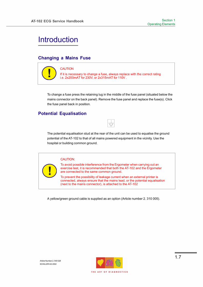
Changing a Mains Fuse
CAUTION
If it is necessary to change a fuse, always replace with the correct ratingi.e. 2x200mAT for 230V, or 2x315mAT for 110V .
To change a fuse press the retaining lug in the middle of the fuse panel (situated below the
mains connector on the back panel). Remove the fuse panel and replace the fuse(s). Click
the fuse panel back in position.
Potential Equalisation
The potential equalisation stud at the rear of the unit can be used to equalise the ground
potential of the AT-102 to that of all mains powered equipment in the vicinity. Use the
hospital or building common ground.
CAUTION:
To avoid possible interference from the Ergometer when carrying out anexercise test, it is recommended that both the AT-102 and the Ergometerare connected to the same common ground.
To prevent the possibility of leakage current when an external printer isconnected, always ensure that the mains lead, or the potential equalisation(next to the mains connector), is attached to the AT-102
A yellow/green ground cable is supplied as an option (Article number 2. 310 005).

1.8
AT-102 Service Handbook
Introduction
Keypad
4 7 8 9 10 11 12 13 14 15
16
1
2 3
5 6
17

1.9Article Number 2. 540 028
SCHILLER AG 2002
AT-102 ECG Service Handbook Section 1Operating Elements
Introduction
1. Softkeys - the function of these keys changes depending on the screen displayed.
The function of these keys is shown on the screen above the keys. If nothing is
written above a softkey, it has no function for the current screen.
2. Auto Mode recording (in Auto mode 1).
Press the Function key (17) followed by the AUTO key (2) for auto mode 2.
3. STOP printout / confirm (new) setting
4. Open / Close paper tray (to replace thermal printing paper)
5. The top figures on the number keys `1` and `2 ` (designated < and >), change the
lead group displayed on the screen, forward and backward resp.
6. Auto sensitivity key - automatically sets the ECG printout sensitivity ( in AUTO mode
only) to the best setting for the signal strength (5mm/mV or 10mm/mV)
7. The top figures on the number keys designated 5, 10, and 20 set the sensitivity of
the ECG both on the screen and on the (manual) printout. The sensitivity is 5, 10 or
20 mm / mV.
8. The top figures on the number keys designated 5/10, 25, and 50 set the speed of the
ECG both on the screen and on the (manual) printout. The speed on the screen can
only be set to 25 or 50 mm/s. The speed of the manual printout can be 5, 10, 25 or
50 mm/s. The 5 and 10 mm/s settings are both on the same key which toggles the
two speeds.
9. Inserts a 1mV reference marker on the screen and printout. Recentres the trace.
10. Toggles the QRS beeper ON/ OFF
11. Myogram filter ON / OFF. The cutoff frequency can be user defined in ̀ Setup`.
12. Delete last typed character.
13. Patient data key. Press this key to enter a new patient or modify the data for the
current one.
NOTE:
The patient data screen, or the ECG screen is the first screen displayed oninital switch on. This is set for user preference in the system settings (Seefollowing).
14. ON / OFF Keys
15. Mains Indicator - lit when mains connected.
16. Press the function key (17) and the UP/DOWN arrows to adjust screen contrast.
When entering patient data use the LEFT/RIGHT arrow keys to move the cursor in
the data field. Use the UP/DOWN arrow keys to go up/down to the next data entry
17. Function Key (Fn). When pressed before another key, initiates the second function of
that key.
For example, second letters on the keypad (è, é, ç, ø @ etc.), are entered by holding
the function key before pressing the letter key.

1.10
AT-102 Service Handbook
Introduction
LCD Screen
The display will vary according to the current task being carried out. In all screens however,
the top and bottom lines always display the same information: the top line displays system
information (time, patient, power source etc.,), and the bottom line always gives the softkey
options.
The following is an example of a typical resting ECG screen.
Items 1, 2 and 3 are in the same position for all screens.
1. Top line - time, date, patient name, and current power source - mains ( ), or
battery ( ). When battery capacity is limited the battery symbol flashes.
2. Softkey designation. Pressing the key below the text carries out the function
indicated. The options available will change according to the screen
displayed.
3. Data acquisition area or data entry area.
5678910
1
2
3
4

1.11Article Number 2. 540 028
SCHILLER AG 2002
AT-102 ECG Service Handbook Section 1Operating Elements
Introduction
Items 4 to 10 are specific for ECG acquisition only:
4. Current Heart Rate (averaged over 4 beats and refreshed every 2 seconds). The HR is
also given on a manual printout. Note that with an auto mode printout the HR is
averaged over the full 10 seconds of the recording.
5. Electrode connections - when a lead flashes it indicates that the electrode resistance
is too high. The electrode(s) must be reapplied.
6. Sensitivity - 5, 10 or 20 mm/mV. Change the sensitivity with the keys 3 (auto), 4, 5
and 6. An `A` in this box indicates that automatic sensitivity is selected (auto mode
printout only).
7. Speed - 25 or 50 mm/s. Change the speed with the keys 8 and 9.
8. Lead indication (leads currently displayed on the screen). Change the lead group with
the < and > keys on the keypad.
9. Myogram Filter indication - 'Filter ON' or 'Filter OFF'. The filter is applied with the filter
key.
Note: the frequency of the filter cutoff is defined in Section 4 Setup.
10. Area for system messages or instructions.

1.12
AT-102 Service Handbook
ECG Settings
The AT-102 ECG and system settings are entered by selecting 'setup' from the initial
screen:
The following pages detail the programmable ECG parameters.
NOTE:
In units where the interpretation option is not installed, interpretation state-ments, cannot be displayed.

1.13Article Number 2. 540 028
SCHILLER AG 2002
AT-102 ECG Service Handbook Section 1Operating Elements
ECG Settings
Use the select softkey to select the different settings
Use the Up/Down softkeys to highlight the various options.
Auto Format 1 and 2
Two separate Auto formats can be defined for the AT-102. Use the NEXT softkey to confirm
setting and to move onto the next screen (Format 2).
ECG Printout
Press the `SELECT` softkey to choose from the following options:
No Printout No printout of the ECG given at the end of an auto mode recording (the
recording can be stored in the memory and printed at a later time if
required).
4*3 + 1 Rhythm Leads are printed in a 4 * 3 format at 25mm/s, with the selected rhythm
lead at the bottom of the page at 25mm/s.
1*12 at 25mm/s Leads are printed in a 1 * 12 format at 25mm/s - no rhythm lead printed.

1.14
AT-102 Service Handbook
ECG Settings
8*5s + 4*10s The first 8 leads printed for 5 seconds and the last 4 leads printed for
10 seconds.
Short at 25mm/s Leads are printed in short form (1 sheet) at 25mm/s.
Long at 25mm/s Leads are printed in long form (2 sheets) at 25mm/s.
Long at 50mm/s Leads are printed in long form (2 sheets) at 50mm/s.
Average Cycles
No Printout No printout of average cycles
4*3, 25mm/s + 2 Rhythm Leads are averaged over the entire 10 second recording and printed
in 4 groups of 3 leads at 25mm/s, with the two selected rhythm
leads at the bottom of the page at 25mm/s.
4*3, 50mm/s + 2 Rhythm Leads are averaged over the entire 10 second recording and printed
in 4 groups of 3 at 50mm/s, with the two selected rhythm leads at
the bottom of the page at 25mm/s.
2*6, 50mm/s + 2 Rhythm Leads are averaged over the entire 10 second recording and printed
in two groups of six at 50mm/s, with the two selected rhythm leads
at the bottom of the page at 25mm/s.
Rhythm Leads
Select the rhythm lead 1 and rhythm lead 2 as described above.
Rhythm Lead 1 Select any lead (I, II, III, aVR, aVl, aVF, V1 to V6)
Rhythm Lead 2 Select any lead (I, II, III, aVR, aVl, aVF, V1 to V6)
Measurements, Markings and Interpretation
Measurements Select yes or no to print a detailed table of measurement results
Markings Select yes or no to print reference markings on the ECG average
cycle print. A vertical marker shows the beginning and end of P wave
and QRS, and the end of the T wave
Interpretation Select yes or no to print interpretation statement
Full details of the interpretation option are given in the SCHILLER ECG Measurement and
Interpretation booklet (art. No. 2.510 179).

1.15Article Number 2. 540 028
SCHILLER AG 2002
AT-102 ECG Service Handbook Section 1Operating Elements
ECG Settings
Filters
There are five different filters which can be set individually as follows:
Baseline filter
The cutoff frequency of the filter is set on the top line. The cutoff can be 0.05Hz, 0.15Hz or
0.3Hz.
Note:
The set value is the lower limit of the frequency range and is normally set to0.05 Hz. The settings 0.15 and 0.30 Hz should only be used when absolutelynecessary, as the possibility exists that they could affect the original ECGsignal, especially the ST segments.

1.16
AT-102 Service Handbook
ECG Settings
Myogram filter
The Myogram filter suppresses disturbances caused by strong muscle tremor. The filter is
applied by pressing the FILTER key (or programmed on as default when the unit is
switched on).
When the Myogram filter is on, `FILTER ON` is displayed in the
information box.
The cutoff frequency is user defined at 25Hz or 35Hz. When ̀ off at
power up` is selected, the Myogram filter is off when the unit is first
switched on.
Note: An ECG recorded in auto mode is stored unfiltered. It is therefore possible to print
the stored ECG either with or without passing the myogram filter. Filter ON is
indicated on the LCD.
Mains filter
The mains filter is an adaptive digital interference filter designed to suppress ac interference
without attenuating or distorting the ECG.
Set the mains filter in accordance with the frequency of your local mains supply.
Baseline Stabiliser (SCHILLER SBS)
The baseline stabiliser greatly reduces the baseline fluctuations without affecting the ECG
signal. The purpose of the stabiliser is to keep the ECG signals on the baseline of the
printout. This filter is only effective in auto mode printout.The Baseline Stabiliser is applied
to a recording (on), or not applied to a recording (off).
Smoothing Filter (SCHILLER SSF)
The smoothing filter (SSF: SCHILLER smoothing filter) is a low pass filter to suppress high
frequency artefacts between the QRS complexes. When this filter is switched on, `SSF` is
shown on the bottom line of the automatic printout.
1.17Article Number 2. 540 028
SCHILLER AG 2002
AT-102 ECG Service Handbook Section 1Operating Elements
ECG Settings
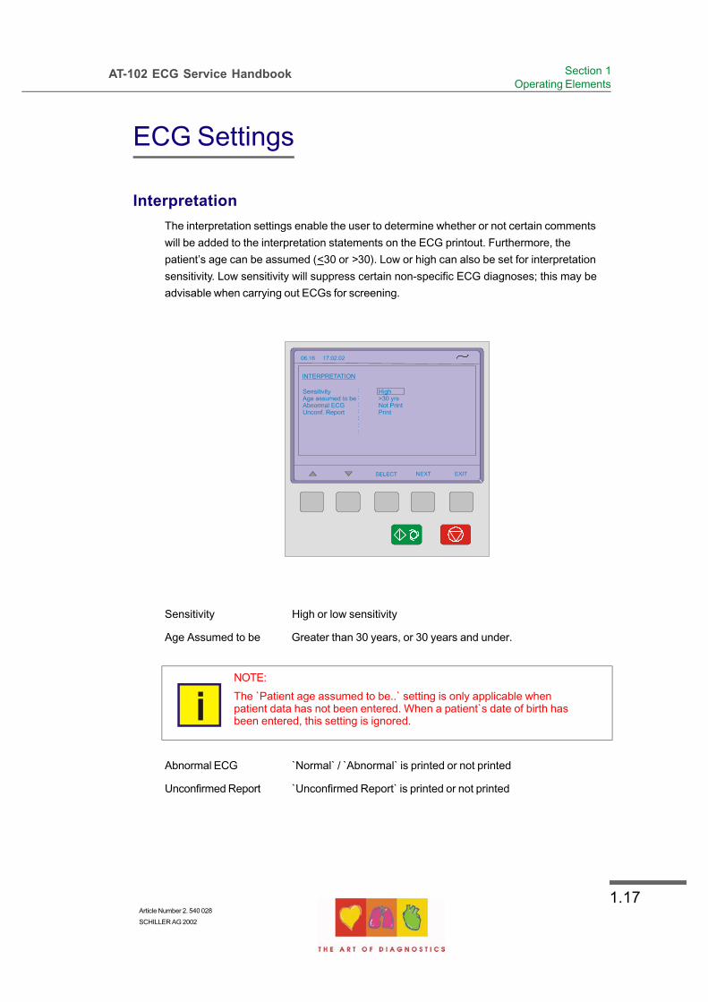
Interpretation
The interpretation settings enable the user to determine whether or not certain comments
will be added to the interpretation statements on the ECG printout. Furthermore, the
patient’s age can be assumed (<30 or >30). Low or high can also be set for interpretation
sensitivity. Low sensitivity will suppress certain non-specific ECG diagnoses; this may be
advisable when carrying out ECGs for screening.
Sensitivity High or low sensitivity
Age Assumed to be Greater than 30 years, or 30 years and under.
NOTE:
The `Patient age assumed to be..` setting is only applicable whenpatient data has not been entered. When a patient`s date of birth hasbeen entered, this setting is ignored.
Abnormal ECG `Normal` / ̀ Abnormal` is printed or not printed
Unconfirmed Report `Unconfirmed Report` is printed or not printed
1.18
AT-102 Service Handbook
ECG Settings
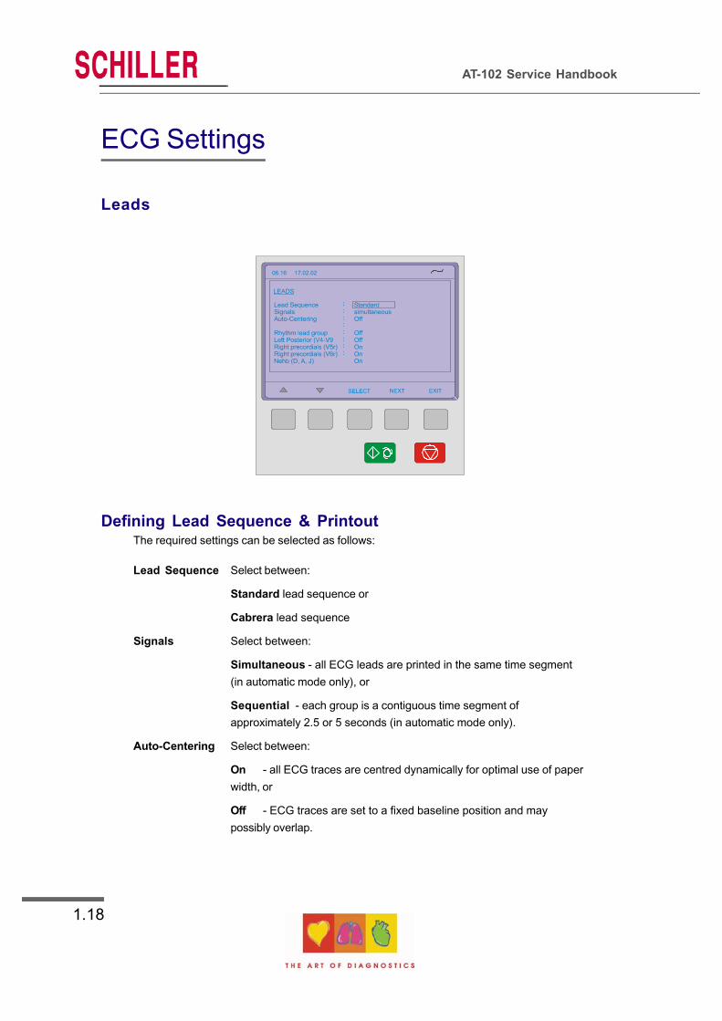
Leads
Defining Lead Sequence & PrintoutThe required settings can be selected as follows:
Lead Sequence Select between:
Standard lead sequence or
Cabrera lead sequence
Signals Select between:
Simultaneous - all ECG leads are printed in the same time segment
(in automatic mode only), or
Sequential - each group is a contiguous time segment of
approximately 2.5 or 5 seconds (in automatic mode only).
Auto-Centering Select between:
On - all ECG traces are centred dynamically for optimal use of paper
width, or
Off - ECG traces are set to a fixed baseline position and may
possibly overlap.

1.19Article Number 2. 540 028
SCHILLER AG 2002
AT-102 ECG Service Handbook Section 1Operating Elements
ECG Settings
The lead group settings allow extra leads to be displayed on the screen when set to `on`.
The following lead groups can be displayed:
Rhythm Lead Group II, avF, III / V2, V4, V5
Left Posterior (V4-V9) V4, V5, V6 / V7, V8, V9
Right Precordials (V5r) V1, V2, V3 / V3r, V4r, V5r
Right Precordials (V6r) V1, V2, V3r / V4r, V5r, V6r
Nehb (D, A, J) D, A, J (only three leads)
The above leads can also be printed when displayed (only in manual mode)
The lead groups are changed both on the screen and on the manual printout with the lead
next/previous keys:

1.20
AT-102 Service Handbook
Stress Settings
The AT-102 Stress ECG settings are entered by selecting 'Setup' and 'Stress Settings' from
the initial screen:
The following pages detail the stress settings for the AT-102.

1.21Article Number 2. 540 028
SCHILLER AG 2002
AT-102 ECG Service Handbook Section 1Operating Elements
Stress Settings
General Settings
Selecting the ERGO Device
Ergo devices available for use with the AT-102 are as follows:
Bikes:
The Ergoline digitally controlled exercise bicycle 900 / 911
SECA CT100 mod.545
Treadmills:
The Ergoline digitally controlled treadmill TM435/TM4000ES
RAM 770CE
MTM-1500
Blood Pressure Entry
Select between Off, Auto and Manual. When Manual is selected the BP screen (for entry of
blood pressure), is displayed 55 seconds before the end the stage. When the stages are
less than one minute long, or a stage is held, then the BP screen is displayed every 2
minutes.
The AUTO function is not available at the time of print.

1.22
AT-102 Service Handbook
Stress Settings
Selecting the Default Test Protocol
Two protocols for a bike and two for a treadmill are available for selection when starting a
stress test - the two protocols displayed when starting a stress test are defined here.
The user defined protocols (one for a treadmill and one for a bike) are defined by the user
(see following page).
Defining the Stage Printout Format
A stage printout is given at the end of every stage. When the stages are less than 2
minutes long, or a stage is held, then a prinout is given every 2 minutes.
The waveforms are averaged to give 4 x 3 plus 1 rhythm lead, or 6 x 2. The rhythm lead
printed is the ST lead defined below.
ST Amplitude Lead
Define the lead that is used for ST measurement. This lead is also printed as the rhythm
lead if set in the stage printout.

1.23Article Number 2. 540 028
SCHILLER AG 2002
AT-102 ECG Service Handbook Section 1Operating Elements
Stress Settings
Defining / Editing Exercise Protocols
For a bicycle the following can be defined:
Protocol Name - The name defined here appears in the general stress settings (when
selecting the two default bike protocol (see previous page)
Base Load - The load in Watts, applied during the warm-up period
Step load - The load increase at every step
Recovery Load - The load applied during the recovery phase
Step Interval - The duration of each step
For a treadmill Protocol, the following can be set:
Protocol Name - As above
Step Interval - The duration of each step
Speed - The individual treadmill speed of each step
Elevation - The individual treadmill elevation of each step

1.24
AT-102 Service Handbook
Stress Settings
Factory programmed Treadmill Protocols
One factory programmed Treadmill protocols is availbale as follows:
Bruce
Stage Duration Speed Elevation
1 3 min 2.7km/h (1.7mph) 10%
2 3 min 4.0km/h (2.5mph) 12%
3 3 min 5.4km/h (3.4mph) 14%
4 3 min 6.7km/h (4.2mph) 16%
5 3 min 8.0km/h (5.0mph) 18%
6 3 min 8.8km/h (5.5mph) 20%
7 3 min 9.6km/h (6.0mph) 22%
Factory programmed Bicycle Protocols
One factory programmed Bicycle protocols is available 252525. This gives a base load
(warmup) of 25W (50W), with a step load for both protocols of 25W and a recovery load of
25W.

1.25Article Number 2. 540 028
SCHILLER AG 2002
AT-102 ECG Service Handbook Section 1Operating Elements
System Settings
The AT-102 system settings are entered by selecting 'setup' and 'system settings' from the
initial screen:
The following pages detail system settings for the AT-102.

1.26
AT-102 Service Handbook
System Settings
Unit
User Identification (User ID)
The user identification is printed on all recordings. The user ID can be the department,
doctor or hospital etc. Select User ID and a blinking cursor is present - enter up to 30
characters via the keypad.
Note: If the unit is reset to the default settings (see following), the user identification must
be re-entered.
Date and Time
Enter the date in the format day.month.year. Enter the time using
the standard 24 hr notation. When set, the ENTER key must be
pressed to confirm.

1.27Article Number 2. 540 028
SCHILLER AG 2002
AT-102 ECG Service Handbook Section 1Operating Elements
System Settings
Language
Several languages are already programmed into the unit. Select the language for the screen
display and for the printout. The language will also set the units used by the system.
The difference between American and English is as follows:
American Standard English
measurements in inches measurements in centimetres
temperature in Fahrenheit temperature in degrees centigrade.
Mains filter setting - 60Hz mains filter setting - 50Hz
date order mm-dd-yy date order dd-mm-yy
Additionally, when American is set, further race settings are given and Spiro diagnosis is
based on ITS recommendations - see Spirometry handbook.
The default language is (Standard (International)) English.
Startup Screen
Here you can specify the first screen to be displayed when the unit is switched on. Select
between patient data screen (for entry of new patient) or data acquisition screen (ECG).
Paper Mode
The internal printer can print on A4 or letter size paper. Set according to the paper used.

1.28
AT-102 Service Handbook
System Settings
Communication
Baudrate Select a Baud rate between 115200 and 9600 Baud, according to the
modem/computer used. Most computers can connect at 115200 Baud
and the standard modem speed is 57600 Baud. If problems are
experienced during transmission reduce the Baud rate.
Mode Select between line (computer connected directly to the RS-232
interface), or modem (for transmission over the phone network)
Phone No. Enter the telephone number preceded by ̀ T` or ̀ P` (tone or pulse).
A comma `,` gives a one second pause in dialling - this may be
necessary for example, if an outside line is required.
Modem Init. Enter the modem initialisation codes. Full details will be found in the
user guide for your modem. However, the modem initialisation must
contain at the minimum, the following commands with the prefix `AT`.
`Q0`- modem sends response
`V0`- numerical response codes
`E0`- no command echo
The standard modem initialisation code is: ATB0L1V0Q0E0S0=0
If in doubt about any of these settings, please contact your phone company and/or modem
supplier.
1.29Article Number 2. 540 028
SCHILLER AG 2002
AT-102 ECG Service Handbook Section 1Operating Elements
System Settings
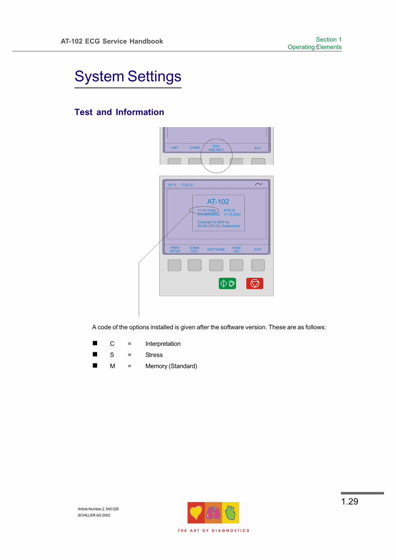
Test and Information
A code of the options installed is given after the software version. These are as follows:
C = Interpretation
S = Stress
M = Memory (Standard)

1.30
AT-102 Service Handbook
System Settings
Obtaining a printout of all current settings
To obtain a printout press the ̀ PRINT SETUP` softkey
A printout of the defined settings will be produced and gives the following information,
depending on the installed software:
Unit designation Software version, Software options installed (C = Interpretation, M
= Memory (standard), S = Stress) and Serial number of the unit
ECG Format (1 and 2) Speed Default speed setting
Auto printout Long (ooo), Short (o) or Suppressed (-)
MECG Average cycles as defined in auto ECG
recording setup (e.g. 4 * 3 (25 mm/s) + 2)
Rhythm leads Leads selected for R1, R2 resp.
Measurements Print - Enabled (+) or Suppressed (-)
Marks Print - Enabled (+) or Suppressed (-)
Interpretation Print - Enabled (+) or Suppressed (-)
Leads Sequence Standard (S) or Cabrera (C)
Signals Printout of signals - Sequential or
Simultaneous
Auto Centering Enabled (+) or Suppressed (-)
Lead Group Rhythm, V9, V4r, V6r, DAJ, ON (+) or OFF (-)
for each lead group
1.31Article Number 2. 540 028
SCHILLER AG 2002
AT-102 ECG Service Handbook Section 1Operating Elements
System Settings
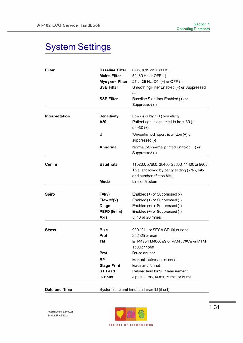
Filter Baseline Filter 0.05, 0.15 or 0.30 Hz
Mains Filter 50, 60 Hz or OFF (-)
Myogram Filter 25 or 35 Hz, ON (+) or OFF (-)
SSB Filter Smoothing Filter Enabled (+) or Suppressed
(-)
SSF Filter Baseline Stabiliser Enabled (+) or
Suppressed (-)
Interpretation Sensitivity Low (-) or high (+) sensitivity
A30 Patient age is assumed to be < 30 (-)
or >30 (+)
U ‘Unconfirmed report’ is written (+) or
suppressed (-)
Abnormal Normal / Abnormal printed Enabled (+) or
Suppressed (-)
Comm Baud rate 115200, 57600, 38400, 28800, 14400 or 9600.
This is followed by parity setting (Y/N), bits
and number of stop bits.
Mode Line or Modem
Spiro F=f(v) Enabled (+) or Suppressed (-)
Flow =f(V) Enabled (+) or Suppressed (-)
Diagn. Enabled (+) or Suppressed (-)
PEFD (l/min) Enabled (+) or Suppressed (-)
Axis 5, 10 or 20 mm/s
Stress Bike 900 / 911 or SECA CT100 or none
Prot 252525 or user
TM ETM435/TM4000ES or RAM 770CE or MTM-
1500 or none
Prot Bruce or user
BP Manual, automatic of none
Stage Print leads and format
ST Lead Defined lead for ST Measurement
J- Point J plus 20ms, 40ms, 60ms, or 80ms
Date and Time System date and time, and user ID (if set)

1.32
AT-102 Service Handbook
System Settings
Communications Test
When this is selected, test options are given for the RS-232 communication port. Use this
test if the RS-232 port is suspected of malfunction. A special test plug is used to carry out
the UART test. Full details if checking the RS-232 port is given in the AT-102 Service
Handbook.
Upgrade/ Update Software
Use the upgrade option to install any available software options (e.g. Exercise). An upgrade
code can be obtained from SCHILLER.
Use the Update option to update the current software.
NOTE:
Details of these procedures are given in Section 5 of this handbook.

1.33Article Number 2. 540 028
SCHILLER AG 2002
AT-102 ECG Service Handbook Section 1Operating Elements
System Settings
Default Settings
To reset the unit to the base default settings, press the `BASE INIT` softkey. As the unit
resets to the default values a message is briefly displayed on the LCD. The base settings
(Defaults) are given on the following page.

1.34
AT-102 Service Handbook
System Settings
Unit Defaults Table
Settings Standard With Interpretation
Language As set As set
Auto Format 1 ECG: 25mm/s, short (o) ECG : 25mm/s, short (o)
Rhythm Leads V1 Rhythm Leads V1, II
MECG: 2*6 (50mm/s + 1)
Measurements: Suppressed (-)
Interpretation: Enabled (+)
Marks: Enabled (+)
Auto Format 2 ECG: 25mm/s, Long (ooo) ECG : 25mm/s, long (ooo)
Rhythm Leads V1 Rhythm Leads V1, II
MECG: none
Measurements: Suppressed (-)
Interpretation: Suppressed (-)
Marks: Enabled (+)
Leads Sequence Standard (S) Sequence Standard (S)
Rhythm On (+) Rhythm On (+)
V9 On (+) V9 On (+)
V4r Off (-) V4r Off (-)
V5r Off (-) V5r Off (-)
DAJ Off (-) DAJ Off (-)
Autom. Centering Enabled (+) Autom. Centering Enabled (+)
Signals Sequential Signals Sequential
Filter Baseline 0.05Hz Baseline 0.05Hz
Mains Filter 50Hz (60Hz) Mains Filter 50Hz (60H
Myogram 35Hz, OFF Myogram 35Hz, OFF
Memory and Communication Baud rate 57600 bps Baud rate 57600 bps
Trans. mode: line Trans. mode: line
Interpretation Settings Suppressed (-)
U: Enabled (+)
A30: Age assummed to be < 30

1.35Article Number 2. 540 028
SCHILLER AG 2002
AT-102 ECG Service Handbook Section 1Operating Elements
System Settings
Settings Standard With Interpretation
Spiro FVC=f(t) on(+) FVC=f(t) on(1)
F=f(v) on(+) F=f(v) on(+)
Diagn.on(+) Diagn.on(+)
PEF (l/min)on(+) PEF (l/min)on(+)
Axis 10 mm/s Axis 10 mm/s
Stress Bike 900 / 911 Bike 900 / 911
Prot 252525 Prot 252525
TM ETM435/TM4000ES TM ETM435/TM4000ES
Prot Bruce Prot Bruce
BP off BP off
Stage Print 4*3 + 1 Rhythm Stage Print 4*3 + 1 Rhythm
ST Lead V5 ST Lead V5
J- Point J + 60msec J- Point J + 60msec

1.36
AT-102 Service Handbook

2.1Article Number 2. 540 028
SCHILLER AG 2002
AT-102 Service Handbook Section 2Functional Overview
Section 2
Functional Overview
.

2.2
AT-102 Service Handbook
Introduction
This chapter provides a functional overview of the AT-102 electronics. The aim of this
overview is to enable the service engineer to identify processing paths in order to help
identify possible faulty modules. A functional block diagram supports the text.
Most of the electronics are mounted on a single main board which is housed in the base of
the two part AT-102 casing.
The main functional areas of the AT-102 are as follows:
On the Main Board:
CPU (68332)
Opto isolated and shielded ECG multiplexer with isolated power supply and patient
interface
Power Supply
Flash EPROM (electrically erasable) 16 Megabytes
In the top assembly
Keyboard
TFT screen
In the base assembly:
Thermal Printer
Paper tray drive motor
Battery

2.3Article Number 2. 540 028
SCHILLER AG 2002
AT-102 Service Handbook Section 2Functional Overview
THE
RM
AL
PR
INTE
R
Pap
er m
ark
dete
ctor
The
rmal
prin
th
ea
d
Prin
ter
mot
or
TO
P A
SS
EM
BLY
LCD
scr
een
Prin
t he
adco
ntro
ller
Ste
pper
mot
orco
ntro
ller
LCD
con
trol
-le
r
Key
boar
din
terf
ace
DC
- D
Cco
nver
ter
refe
renc
evo
ltage
Pow
er r
ail
stab
ilisa
tion
Sig
nal
mul
tiple
xer
(PW
M)
-5V
i
+ 2V
i
+5V
i
-5V
i
-10V
i
PAT
IEN
T I
SO
LA
TIO
N (
4kV
rms)
Vol
tage
regu
lato
r
Sw
itchi
ngvo
ltage
reg
.
+5V
ref
+5.2
V
+24V
Ove
rvol
tage
prot
ectio
n
Und
ervo
ltage
prot
ectio
n
Vol
tage
sen
se&
con
vers
ion
MO
NM
otor
run
ning
BLO
W10
.3V
MO
N
+U
S
ON
/ O
FF
cont
rol
Bat
tery
cha
rger
&vo
ltage
reg
ulat
orR
ectif
icat
ion
Vol
tage
sen
se+
US
+U
S
+5.2
V
+24V
12 V
Bat
tery
Mai
nsLE
D
Mai
nsco
nnec
tor
+U
MA
IN B
OA
RD
MK
18
- 1LC
D p
ower
supp
ly
P2
P4
(par
t)
P8
P17 P7
P11P12
MU
X
CTRL
+Bat
t
OF
F fr
om C
PU
ON
fro
m k
eybo
ard
SI1
SI2
Vol
tage
regu
lato
r
AT-
102
Dire
ctF
unct
ion
Key
s
Inpu
t am
pli-
fier
and
filte
rP
atie
ntco
nnec
tor
P1
+5.2V
i
DC
- D
Cco
nver
ter
CP
U
Key
boar
d
P10
RS
-2
32
RS
-232
Inte
rfac
e
Ext
Prin
ter
Ext
. Prin
ter
Inte
rfac
e
P14
P15

2.4
AT-102 Service Handbook
MK 18 - 1 Main Board
Power Supply
The mains supply is full wave rectified to produce an unregulated dc supply of
approximately 30 V (+U). This voltage is used by a switched voltage generator to produce
+UD (13.5V). +UD charges the battery when mains is connected. When mains is not
connected, +UD is the battery voltage.
An ON/OFF control logic switches +UD to three voltage regulators. The unit is switched on
directly from the keyboard and then held on from the CPU. Detection of overvoltage on
either the 5.2 V or 24 V supplies directly switches the unit off. Similarly when an
undervoltage is detected on +US (indicating overcurrent) the unit is directly switched off.
The mains LED is lit directly when mains is connected. The same circuit also monitors the
switched dc supply (+US) and activates signal +BATT when the unit is switched on and
mains is not connected (i.e. the unit is running on battery power).
A Battery low signal (BLOW) is set to logic 0 when battery voltage (+US) falls to 11.3 V. A
circuit compensates for voltage drop when the printer stepper motor is active and the BLOW
signal is active only at 10.3 V.
The battery voltage is also monitored directly by the CPU which switches the unit off when
the voltage falls below approximately 9.4 V.
Program and ECG Memory
A FLASH EPROM (electrically erasable) contains the unit software (512 kByte) and the
stored ECG data. The two memory blocks can be independently erased. It is possible to
update the software via the RS-232 serial interface.
The a serial EEPROM stores the unit base settings.
Thermal Print Head Controller
The Thermal Print Head is controlled by a print head controller and a CPU timer circuit. The
print head controller serialises the data for the print head and the timer circuit controls how
long current is applied to the head, and thus the intensity of the printout.

2.5Article Number 2. 540 028
SCHILLER AG 2002
AT-102 Service Handbook Section 2Functional Overview
MK 18 - 1 Main Board
Printer Timing
Strobe generation is controlled by the CPU when one complete pixel line of data is ready to
be written. Pulse length of STRB1 and STRB2 (each of which controls half of the pixel
array) depends from TPH temperature and so form the pulse width of the TPHT signal.
Paper Mark
The pulsed paper mark signal from the printer is fed to a comparator. A detected papermark
sets PMARK at the output of comparator (U44), to logic 0.
Power On Reset
The Power on reset circuit controls the master reset of the CPU. This circuit has two
functions as follows:
To provide a delay on initial switch-on to ensure that the power supply is fully
stabilized and give the 200ms reset time required by the 68332 processor.
To disable the unit if the +5V rail drops below +4.75V.
Stepper Motor Controller
The printer stepper motor controller sets the speed of the printer motor with a clock
frequency dictated by the master CPU.
The purpose of the stepper motor controller circuit is to ensure that the motor speed
requested by the microprocessor is achieved and maintained.
ECG Isolated Power Supplies
DC/DC converter circuits produce all the isolated power voltages required by the ECG
Amplifier circuit.
The -2.0Vi and the 2Vi isolated reference voltages are generated from the -5Vi supply.
Note: When taking measurements always ensure that the isolated ground is used for
reference.

2.6
AT-102 Service Handbook
MK 18-1 Main Board (cont.)
ECG Signal
The incoming ECG signals RA, LA, and C1 to C6 are low-pass filtered and applied to non-
inverting operational-amplifiers giving a gain of 11. The signals are further band pass filtered
(approximately 0.05 Hz to 470Hz) and amplified by 23 before being applied to the
multiplexer.
The multiplexer sampling rate is 1000Hz.
Noise Damping
The right leg electrode to the patient is the signal ground reference signal. To assist in
cancelling some patient noise and thus reducing incoming signal distortion, the incoming
signal from the patient left leg electrode is phase shifted 180o. This phase shifted signal is
then used by the signal ground reference to cancel (or reduce) patient induced noise.
RS-232 Interface
This is a standard RS-232 / V.24 interface connected to the MK 18-10 main board. The
communications controller contains a USART and interface circuit which performs the
parallel / serial and serial / parallel conversion for the transmission and reception of data
and provide signal level compatibility with RS-232 standard.
External Modem
An external modem can be connected to the RS-232 output from the AT-102 and be used
for transmitting memory contents over a telephone line.

2.7Article Number 2. 540 028
SCHILLER AG 2002
AT-102 Service Handbook Section 2Functional Overview
Top Assembly
LCD Screen
The LCD power supply produces the high voltage for the LCD backlight and the contrast
voltage. LCD data is stored in a video RAM and the LCD controller converts the data to the
proper form for the LCD screen.
Alphanumerical Keyboard
The keyboard is a matrix style circuit which is periodically scanned by the processor via the
keyboard interface circuit. It is an integral part of the top assembly and can not be
individually replaced.

2.8
AT-102 Service Handbook

3.1Article Number 2. 540 028
SCHILLER AG 2002
AT-102 Service Handbook Section 3Fault Finding
Section 3
Fault Finding
.

3.2
AT-102 Service Handbook
Introduction
The AT-102 is designed to be simple to use and simple to service: the service philosophy of
the AT-102 is module and board replacement (no details are given in this book for board
repair). The purpose of this chapter is to provide fault-finding procedures that will quickly
and efficiently identify a fault to a specific module. Fault-finding procedures are designed so
that test equipment is kept to a minimum.
The AT-102 contains the following modules:
MK 18-1 Main Board including main and LCD power supplies
LCD screen assembly
Alphanumerical keyboard (integral part of the top assembly)
Printer assembly
Paper tray motor
An initial fault-finding table is provided detailing general fault indications. Use the
procedures on the following pages to indicate a faulty area or module. In most cases the
fault finding tables should indicate the most likely faulty area. When more than one module
is stated, the first module given is the one most likely to contain the fault. Other modules
given should be checked in the order given. When a module has been replaced specific test
parameters and setting-up of the module may be applicable. The removal and replacement
instructions for all replaceable modules, along with any setup or check procedures
required, are given in Chapters 4 and 5.
If the initial fault-finding table does not indicate the area where the fault exists, re-check all
the settings and parameters that have been entered. If these are correct, check the
software.
General Check Procedures
The procedure detailed here is a general confidence check of the unit after an internal
module or board has been replaced. It is not a full functional test (which can only be carried
out with dedicated equipment in the factory) but is intended to provide a general confidence
check in all the major AT-102 functional areas. The instructions given here are guides to the
basic functions. If more operating information is required (general settings, comprehensive
menu guides etc.) please refer to Chapter 1 in this publication or the AT-102 user guide.

3.3Article Number 2. 540 028
SCHILLER AG 2002
AT-102 Service Handbook Section 3Fault Finding
Fault Finding Chart
IS THE GREEN MAINSLED LIT?
NO
CONNECT MAINSTO THE UNIT
AND SWITCH ON
FUSE OK?NO
YES
FUSE OK?NO
DISCONNECT THE MAINSSUPPLY AND CHECK THE
MAINS FUSES (IN THEMAINS MODULE)
INVESTIGATE THE REASONFOR THE RUPTURED FUSE
YES
AT-102 Initial Fault Diagnosis Chart (Sheet 1)
CHECK THE BATTERY, THEBATTERY LEADS AND THEBATTERY CONNECTORSFOR SHORT CIRCUITS.
REPLACE FUSE ANDSWITCH ON. IF THE FUSE
IS STILL RUPTURINGREPLACE THE MAINBOARD
GO TO FAULT DIAGNOSIS(SHEET A - POWER PRO-
BLEMS)
NOTE:
The removal and replacement instructions and the location of all boards, cableassemblies and connectors are given in Chapter 4.
PRESS THE<ON> KEY
ENSURE THAT THEVOLTAGE SELECTOR IS
CORRECTLY SET.REPLACE THE MAINS
FUSE AND SWITCH THEMAINS ON
DOES THE LCD LIGHT?NO
YES
SHEETTWO
GO TO FAULT DIAGNOSIS(SHEET B - POWER PRO-
BLEMS)
GO TO FAULT DIAGNOSIS(SHEET C - GENERAL PRO-
BLEMS)
A
YES

3.4
AT-102 Service Handbook
AT-102 Initial Fault Diagnosis Chart (Sheet 2)
YES
A
FROMSHEETONE
IS THELCD)
READABLE ?
NO
MONITORDISPLAYS DATA ?
YES
NO
NO
YES
DO THE RS INTERFACESFUNCTION?
GO TO FAULT DIAGNOSISCHART (SHEET H -
COMMUNICATION PRO-BLEMS)
NO
YES
DOES THE EXERCISETEST FUNCTION?
GO TO FAULT DIAGNOSISCHART( SHEET F -
EXERCISE MODE PRO-BLEMS)
NO
YES
DOES THE SPIROMETRYTEST FUNCTION?
GO TO FAULT DIAGNOSISCHART (SHEET G -
SPIROMETRY PROBLEMS)
CHECK THE LCDCONTRAST CONTROL .
REPLACE THEMAIN BOARD
NO
YES
PRESS<PRINT SCREEN>. DOESTHE PRINTER FUNCTION
ATALL?
REPLACE THEMAIN BOARD
CHECK CABLE ASSEMBLIESCHECK CABLE ASSEMBLYFROM MAIN BOARD TO
PRINTER. CHECK POWERSUPPLY TO MOTOR
REPLACE:1. MAIN BOARD
2. THERMAL PRINTER
NOARE STRAIGHTLINE ECG TRACESDISPLAYED ON THE
LCD ?
YES
CHECK ALL PARAMETERSETTINGS. CHECK THE
TEST SCREEN ANDENSURE THAT PARAME-
TERS ARE IN TOLERANCE.CONTACT SCHILLER IF
FAULT CANNOT BE FOUND
NO
YES
DOES THE PAPERTRAY EJECTION WORK
CORRECTLY?
NO
YES
PRINTER MOTORFUNCTIONED?
GO TO FAULT DIAGNOSISCHART (SHEET B - POWER
PROBLEMS). IF THE PO-WER SUPPLY IS OK CHECK
THE PRINTER MOTOR.
NO
YES
GO TO FAULT DIAGNOSISCHART (SHEET D -
PRINTER PROBLEMS)
CONNECT A PATIENT SIMU-LATOR TO THE ECG
CONNECTOR AND SWITCHON
IS THEPRINT QUALITY
GOOD? IS THE PRINTERFUNCTIONINGCORRECTLY?
NO
ARE ECG TRACESDISPLAYED ON
THE LCD?
GO TO FAULT DIAGNOSISCHART (SHEET B - POWER
PROBLEMS). IF THE PO-WER SUPPLY IS OK
REPLACE THE MAINBOARD
NODOES THE PRINT-
OUT GIVE THE ECGTRACES AND PATIENT
DATA?
YES
1. CHECK SETTINGS(SECTION 1) FOR FORMAT,
DATA, PRINTER, ETC.2. CHECK PRINTER
(SHEET D)3. CHANGE THE MAIN
BOARD
ENSURE THAT THEBATTERIES ARE FULLY
CHARGED. REMOVE THEPAPER TRAYAND ENSURE
THAT THE MECHANICALWORMDRIVE IS NOT
JAMMED. CHECK THE DCMOTOR FOR OPENCIRCUIT. CHANGE:
1. THE PAPER TRAY MOTOR2. THE INTERFACE BOARD
PRESS THE <AUTO START>KEY AND WAIT FOR THE
PRINT-OUT
YES
3.5Article Number 2. 540 028
SCHILLER AG 2002
AT-102 Service Handbook Section 3Fault Finding
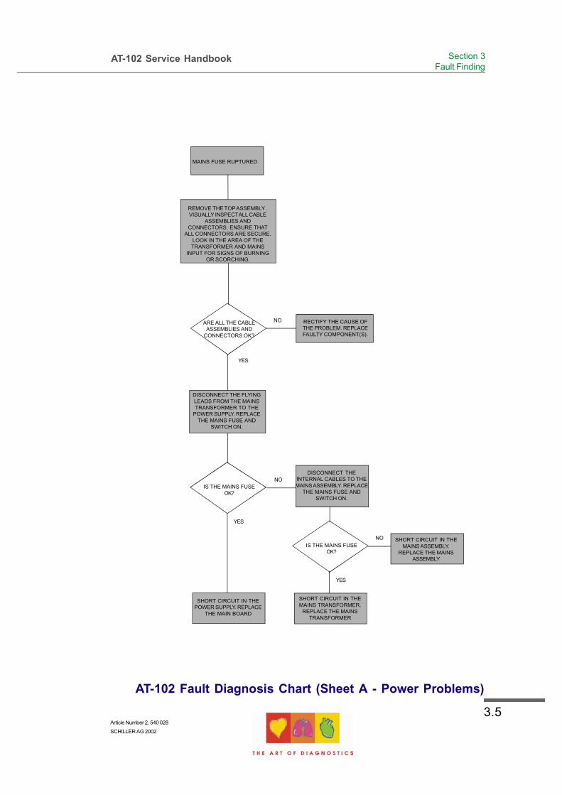
AT-102 Fault Diagnosis Chart (Sheet A - Power Problems)
NO
YES
ARE ALL THE CABLEASSEMBLIES AND
CONNECTORS OK?
IS THE MAINS FUSEOK?
NO
YES
SHORT CIRCUIT IN THEMAINS TRANSFORMER.
REPLACE THE MAINSTRANSFORMER
SHORT CIRCUIT IN THEPOWER SUPPLY. REPLACE
THE MAIN BOARD
IS THE MAINS FUSEOK?
YES
DISCONNECT THE FLYINGLEADS FROM THE MAINSTRANSFORMER TO THE
POWER SUPPLY. REPLACETHE MAINS FUSE AND
SWITCH ON.
NO
REMOVE THE TOPASSEMBLY .VISUALLY INSPECTALL CABLE
ASSEMBLIES ANDCONNECTORS. ENSURE THAT
ALL CONNECTORS ARE SECURE.LOOK IN THE AREA OF THETRANSFORMER AND MAINS
INPUT FOR SIGNS OF BURNINGOR SCORCHING.
SHORT CIRCUIT IN THEMAINS ASSEMBLY.
REPLACE THE MAINSASSEMBLY
RECTIFY THE CAUSE OFTHE PROBLEM. REPLACEFAULTY COMPONENT(S).
DISCONNECT THEINTERNAL CABLES TO THEMAINS ASSEMBLY. REPLACE
THE MAINS FUSE ANDSWITCH ON.
MAINS FUSE RUPTURED

3.6
AT-102 Service Handbook
AT-102 Fault Diagnosis Chart (Sheet B - Power Problems)
NO
YES
REMOVE THE TOPASSEMBLY. VISUALLYINSPECT ALL CABLEASSEMBLIES AND
CONNECTORS. ENSURETHAT ALL CONNECTORS
ARE SECURE. CHECK THECABLE ASSEMBLY FROMTHE POWER SUPPLY TO
THE TOPASSEMBLY.
ARE ALL THE CABLEASSEMBLIES AND
CONNECTORS OK?
NO
YES
CONNECT A DVMACROSS THE MAINS
TRANSFORMER.
REPLACE THE MAINSTRANSFORMER
NO
YES
ARE ALL POWERSUPPLIES OK?
REPLACE THEMAIN BOARD
RECTIFY THE CAUSE OFTHE PROBLEM. REPLACEFAULTY COMPONENT(S).
IS THE AC VOLTAGEREADING APPROX.
18 V?
POSSIBLE FAULT IN THEPOWER SUPPLY. CHECK ALL
POWER RAILS.
1. REPLACE THE CABLEASSEMBLY BETWEEN THE
MAIN BOARD AND THE LCD(BASE ASSEMBLYTO TOP
ASSEMBLY).2. REPLACE THE MAIN
BOARD3. REPLACE THE LCD.

3.7Article Number 2. 540 028
SCHILLER AG 2002
AT-102 Service Handbook Section 3Fault Finding
YES
AT-102 Fault Diagnosis Chart (Sheet C - General Problems)
NOARE ALL THE CABLEASSEMBLIES AND
CONNECTORS OK?
RECTIFY THE CAUSE OFTHE PROBLEM. REPLACEFAULTY COMPONENT(S).
NO
YES
ARE ALL POWERSUPPLIES OK?
REPLACE THEMAIN BOARD
CHECK ALL POWERRAILS
REMOVE THE TOPASSEMBLY. VISUALLYINSPECT ALL CABLE ASSEMBLIES AND
CONNECTORS. ENSURE THAT ALLCONNECTORS ARE SECURE.
CHECK THE LCD CONTRAST CONTROL.CHECK THE CABLE ASSEMBLY BETWEEN
THE POWER SUPPLYAND THE LCD(BOTTOM ASSEMBLY TO TOP ASSEMBLY).
REPLACE REPLACE THE LCD. REPLACE THEVIDEO/LCD CONVERTER (MAIN BOARD)

3.8
AT-102 Service Handbook
AT-102 Fault Diagnosis Chart (Sheet D - Printer Problems)
ENSURE THAT GOODQUALITY, FRESH PAPER ISINSTALLED IN THE PAPER
TRAY. CHANGE IFNECESSARY.
NO
YES
YES
DOES THE PROBLEMSTILL EXIST?
DOES THEPAPER JAM OR NOT
STOP AT THECORRECTPOSITION ?
CHECK AND ADJUST THEPAPER MARK DETECTORAND CURRENT LIMITER
THRESHOLDS AS DETAILEDIN CHAPTER 5.
REPLACE:1. MAIN BOARD
2. THERMAL PRINTER
CARRY OUT THE PRINTERCHECK DETAILED IN
CHAPTER 5. REPLACE THETHERMAL PRINT HEAD IF
NECESSARY
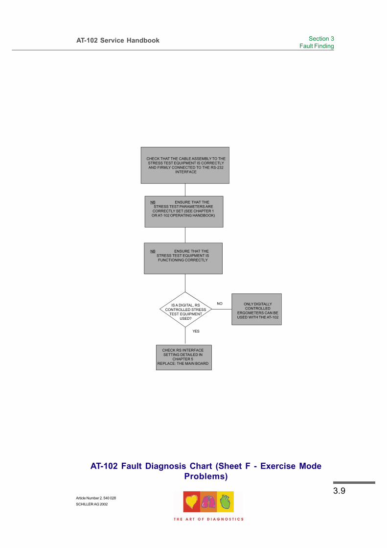
3.9Article Number 2. 540 028
SCHILLER AG 2002
AT-102 Service Handbook Section 3Fault Finding
AT-102 Fault Diagnosis Chart (Sheet F - Exercise ModeProblems)
NO
YES
NB ENSURE THAT THESTRESS TEST PARAMETERS ARE
CORRECTLY SET (SEE CHAPTER 1OR AT-102 OPERATING HANDBOOK)
NB ENSURE THAT THESTRESS TEST EQUIPMENT ISFUNCTIONING CORRECTLY
IS A DIGITAL, RSCONTROLLED STRESS
TEST EQUIPMENTUSED?
CHECK RS INTERFACESETTING DETAILED IN
CHAPTER 5REPLACE: THE MAIN BOARD
CHECK THAT THE CABLE ASSEMBLY TO THESTRESS TEST EQUIPMENT IS CORRECTLYAND FIRMLY CONNECTED TO THE RS-232
INTERFACE
ONLY DIGITALLYCONTROLLED
ERGOMETERS CAN BEUSED WITH THE AT-102
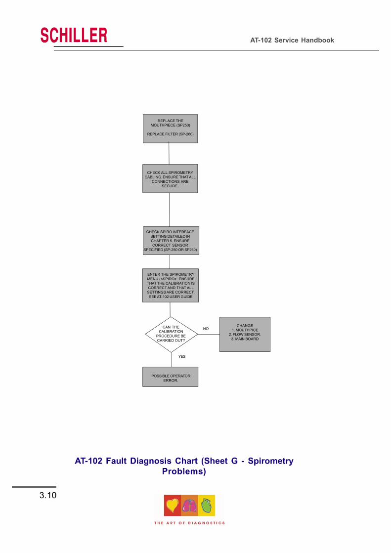
3.10
AT-102 Service Handbook
AT-102 Fault Diagnosis Chart (Sheet G - SpirometryProblems)
NO
YES
ENTER THE SPIROMETRYMENU (<SPIRO>. ENSURETHAT THE CALIBRATION ISCORRECT AND THAT ALLSETTINGS ARE CORRECT.SEE AT-102 USER GUIDE
POSSIBLE OPERATORERROR.
REPLACE THEMOUTHPIECE (SP250)
REPLACE FILTER (SP-260)
CAN THECALIBRATION
PROCEDURE BECARRIED OUT?
CHANGE1. MOUTHPICE
2. FLOW SENSOR.3. MAIN BOARD
CHECK ALL SPIROMETRYCABLING. ENSURE THATALL
CONNECTIONS ARESECURE.
CHECK SPIRO INTERFACESETTING DETAILED INCHAPTER 5. ENSURECORRECT SENSOR
SPECIFIED (SP-250 OR SP260)

3.11Article Number 2. 540 028
SCHILLER AG 2002
AT-102 Service Handbook Section 3Fault Finding
AT-102 Fault Diagnosis Chart (Sheet H - Communication (RS)Problems)
CONFIRM SETTINGS INTHE RS CHECK
PROCEDURE DETAILED INCHAPTER 5.
NO
SETTING CORRECT?
YES
POSSIBLE OPERATORERROR.
CHECK ALL CABLEASSEMBLIES. REPLACE IF
NECESSARY
1. CHECK THE +12V AND -12VSUPPLY VOLTAGES
2. CHANGE THE MAIN BOARD
ENTER SETTINSG MENUCHECK THAT ALL SETTINGS(
LINE/MODEM, RECORD/BLOCK,PARITY, STOP BIT AND THE BAUDRATE) ARE CORRECT FOR THE
APPLICATION AND ARE THESAME IN BOTH DEVICES.

3.12
AT-102 Service Handbook
Functional Check
Test Procedure ResultCorrective action if result not
OK
Connect unit to mains supply. Mains indicator (LED) is lit. Check mains fuse on the back paneland replace if necessary.If problem remains, replace main boardMK 18-1
Switch the unit on by pressingthe ON key on the keyboard.
If no ECG simulator is connected, ashort audible alarm is generated andthe lead indications in the displayare flashing..
LCD screen comes on and showsthree ECG traces and a number ofstatus indications.
ECG traces are barely visible
No traces visible on the LCDscreen.
Ignore or connect ECG simulator
Check power board, ECG and mainboard.
Open the unit and check that the twowire connection from the power supplyto the LCD assembly is properlyconnected (high-voltage backlight). Ifproblem remains, replace LCDassembly.
Check that the signal cable from themain board to the LCD assembly isproperly connected. If problem remains,check LCD assembly, power, ECG andmain board.
Connect an ECG simulator tothe ECG connector on theside panel and switch ON.
Three ECG traces, heart rate,sensitivity, time scale and status oflead connections are shown on thescreen.
If a lead alarm is flashing, check thatthe lead is properly connected
Press the MAN Start key. Six leads are printed and are ofgood quality.
If not, reset to default settings and tryagain. Open the case and inspect allcable assemblies and connectors.Check printer alignment. Run printertest (see next page).Check / replace printer motor.Replace main board MK 18-1.Replace paper tray and completeprinter assembly.
Press AUTO START and waitapproximately 10 seconds forthe printout to commence.
A preprogrammed printout isproduced.
If not as programmed, check allsettings. If problem remains, replacemain board MK 18-1.
Switch the unit OFF and leaveconnected to the mains supplyfor 10 hours or more tocharge the battery.
Disconnect the mains andswitch the unit ON.
Battery symbol is shown on the LCDscreen.
Run the unit on battery powerfor approximately an hour.
Unit fully operational. Nodegradation.
If not, check battery and replace ifnecessary.
Run the unit more than 4hourson battery power .
Battery symbol does not startflashing before 4 hours .
If the unit does run for 4 hours onbattery power it indicates a weakbattery. Replace as necessary.

3.13Article Number 2. 540 028
SCHILLER AG 2002
AT-102 Service Handbook Section 3Fault Finding
Thermal Printer Check
To check the printer and to ensure that every pixel is operational, a built-in printer test is
provided. Carry out the printer check from the ECG acquisition screen by pressing the FN
key followed by the MANUAL PRINT softkey:
+
A `wavy line` test printout is given. Other test patterns are available - toggle the test
patterns with the lead arrow keys.
Carefully examine the printout and ensure that all the lines are even and uninterrupted. Any
faulty print-head pixels will be seen as a horizontal white line. Examine the printout for
evenness of print
Faulty pixel shown as a
horizontal line on the test
printout. (exaggerated on
this example for clarity)
If a faulty pixel is detected the printer must be replaced. If the printout is uneven (for
example darker at the top than at the bottom), it indicates that the printer alignment is not
correct. If the printout is too faint or too dark, check the paper; old paper, paper that has
been exposed to light for a long period, or poor quality paper can all adversely effect the
print quality. A too light or too dark printout also indicates that the TPH temperature is
incorrect. Change the Printer.
NOTE:
The ' shelf life' of the printer paper is not indefinite. Old paper, paper that hasnot been stored in a cool damp free environment, or paper that has beenexposed to excessive heat can adversely effect the quality of the print.

3.14
AT-102 Service Handbook
Thermal Printer Check
Print Head Alignment and Print Head Tension
The print head tension (the pressure that the print head exerts on the printer paper) is
achieved with two springs exerting pressure on the print head: the print head tension cannot
be adjusted. Similarly print head alignment is fixed and cannot be adjusted. If the print head
tension or print head alignment is not correct change the printer.
Thermal Printer Fault Diagnosis
Possible Printer Problem Corrective Action
Paper jams or does not stop atcorrect position.
Clean paper mark detector with a 70%alcohol solution. Allow to dry completely.Ensure that good quality, fresh paper isinstalled.Change the PM detector / Change thePrinter Motor / changes the completeprinter
Printout uneven; Fading at top orbottom.
Check evenness of spring pressure of theprinter to roller.Check roller for wear and symetry.Clean print head (pixel array) with alcohol.Ensure that good quality, fresh paper isinstalled. Change the printer, change themain board.
Faulty pixel. Clean print head (pixel array) with alcohol.Replace printer.
Printout too faint or too dark;General quality poor.
Clean print head (pixel array) with alcohol.Ensure that good quality fresh paper isinstalled. Change printer , change mainboard.

3.15Article Number 2. 540 028
SCHILLER AG 2002
AT-102 Service Handbook Section 3Fault Finding
RS-232 Interface (and Spiro Check)
There are no specific tests that can be performed on the RS-232 interface. However the RS-
232 (UART) settings can be checked to ensure correct protocol and speed. If a spiro sensor
is connected to the RS-232 connector, the sensor type can be displayed to ensure that it is
the correct type. The Comm test screen is entered for the settings screen:
(MENU) >SETUP > SYSTEM SETTING > TEST and INFO > COMM TEST
You are then prompted to select UART TEST and (only if a spiro sensor is connected to the
RS-232 interface), SPIRO SENSOR.
When UART TEST is selected the current Baud rate, RTS and CTS settings are displayed.
When SPIRO SENSOR is selected the sensor type is displayed (SP-250 or SP-260), and
the software version of the spirometry software.

3.16
AT-102 Service Handbook

4.1Article Number 2. 540 028
SCHILLER AG 2002
AT-102 Service Handbook Section 4Module Removal and Replacement
Section 4
Module Removal andReplacement

4.2
AT-102 Service Handbook
Remove topassembly
In Top assemblyaccess to :
In Base assemblyaccess to :
Battery packconnectors
Paper trayassembly and
motor
Main Board MK18-1
ECG and batterycharge voltagepotentiometers
Thermal printer
LCD screenassemblyKeyboard
Remove topassembly
Mains transformerand connector

4.3Article Number 2. 540 028
SCHILLER AG 2002
AT-102 Service Handbook Section 4Module Removal and Replacement
Introduction
This Chapter provides an overview of the procedures to remove and replace the modules that
are spared at service level. The instructions given in this chapter are autonomous, with each
module containing the following:
• The prerequisites that must be fulfilled before removing of the module
• Tools and equipment that are required to remove and replace the module and to carry
out the functional checks and adjustments
• Removal Procedures
• Replacement Procedures
• Checks and Tests that must be carried out after replacement.
Any adjustments, jumper settings, special checks or functional procedures that are
required during a procedure, are detailed in the relevant step.
In-text diagrams support the text where required and provide location details of connectors,
test points and adjustment potentiometers.
Specific warnings and cautions are given where applicable. Warnings indicate potential
danger that could cause personal injury. Cautions indicate areas that could cause damage
to the equipment.
If a key operation or menu selection is required, the key sequence required is given in bold
letters. The character (or character string) given is the actual character that is printed on the
key. When a key sequence is provided it must be followed in the order given.

4.4
AT-102 Service Handbook
Safety Notices
WARNINGS
Before commencing any removal or replacement procedures ensure that the mainspower supply is switched off and that the mains cable is removed.
Certain checks and adjustments can only be carried out with the top assemblyremoved and with mains connected. When carrying out these procedures bewarethat potentially lethal voltages are present.
CAUTIONS
The AT-102 contains static sensitive CMOS components; observe antistatic precau-tions:
When carrying out any maintenance procedures always place the unit on an earthedantistatic mat.
Personnel must be earthed when handling any boards or components
Always use an antistatic bag when transporting boards or components
The unit is susceptible to abrasion damage. To prevent scratching, always place theunit on a soft, non-abrasive cloth when carrying out maintenance procedures.
Take care not to place any strain on the connecting ribbon cable when removing thetop assembly. Ensure that the cable assembly is not crimped or twisted and thatthe top assembly is not placed on the cable assembly.
Care must be taken when removing and replacing connectors. Never use force.Never strain the cable assemblies.
The procedural steps given for each module must be followed in the order given.

4.5Article Number 2. 540 028
SCHILLER AG 2002
AT-102 Service Handbook Section 4Module Removal and Replacement
Physical Overview
The AT-102 unit is enclosed in a two part, medical standard, moulded plastic case.
The top part contains the keyboard and the LCD screen with the base section containing
all the electronics of the unit, the RS-232 interface, the thermal printer, the paper tray, the
battery and mains transformer.
The electronics of the unit are contained on a single double sided printed circuit board,
the main board (MK 18-1 ). This board is secured on spacers moulded in the base
section.
The battery is secured in position in a moulded recess accessed from the bottom of the
units, and the mains transformer is secured on spacers above the printed circuit board.
The thermal printer is mounted on spacers moulded to the base and the paper tray motor
mounted in a similar way.

4.6
AT-102 Service Handbook
Exploded View Lower Casing
Mains
Connector
DC Motor with
Cable (for
paper tray)
Printer
Motor
Paper Mark
Detector
Thermal Print
Head
EMC shield (ECG
Processing Part)
Main Board MK 18-1
Mains
Transformer
Battery
Casing Securing
Screws (x6)
Printer
RollerToothed
Wheel
Paper Tray Worm
Drive
Paper Tray
EMC shield
IMPORTANT
Mains Isolation
Shield. This must
placed between
the mains
transformer and
board

4.7Article Number 2. 540 028
SCHILLER AG 2002
AT-102 Service Handbook Section 4Module Removal and Replacement
Exploded View Upper Casing
LCD
Keyboard Foil
Recess for LCD

4.8
AT-102 Service Handbook
Prerequisites, Test Equipment, Tools,and Accessories
The following list gives the tools, test equipment and accessories required to carry out all
removal and replacement procedures, functional tests, calibration procedures and
adjustments that can be carried out on the AT-102. The test equipment given here is
general. If specific recommendation for test equipment is required, please contact the
SCHILLER service department.
Digital Voltmeter
Selection of cross-bladed, posi-drive and flat-bladed screwdrivers
Cleaning agent such as Trichlorethylene
Selection of spanners
Flat ended pliers
Double-sided tape
ECG Patient Simulator, e.g. phantom 320.
SCHILLER Patient Cable
Low abrasion antistatic mat
General Prerequisites
The unit must be placed on an antistatic mat and antistatic precautions observed
when any maintenance is carried out on the AT-102. The room temperature should be
between 18 and 28 degrees.
The safety notices at the beginning of this section must be read and understood
before carrying out any of the removal and replacement procedures detailed here.
Part Numbers
The part numbers for all replaceable items are given in Chapter 6.

4.9Article Number 2. 540 028
SCHILLER AG 2002
AT-102 Service Handbook Section 4Module Removal and Replacement
Opening and Closing the Case
Top Assembly Removal
The Top Assembly is secured to the base assembly with seven recessed screws. Access
to the screws is gained from the underside of the unit. To remove the Top Assembly,
proceed as follows
WARNING
Ensure that the mains cable is removed.
1. Turn the unit up-side-down and rest on a soft antistatic cloth.
2. Unscrew and remove the six countersunk retaining screws and washers situated in
the extreme corners and edges of the unit.
4. Grasping the top and bottom of the unit to ensure that the two assemblies cannot
part, carefully return the unit to the standing position.
5. Gently lift the Top Assembly sufficiently to gain access to the interconnecting
cables. Disconnect the cable assembly between the main board MK 18-1 and the
keyboard and the ribbon and dual-wire cable assemblies between the power supply
and the LCD screen board.
6. Gently lift the Top Assembly away from the Base Assembly and place on a soft
cloth.

4.10
AT-102 Service Handbook
Opening and Closing the Case
Support the top casing in an
`upright` position to prevent
straining the cable assemblies
and connectors.

4.11Article Number 2. 540 028
SCHILLER AG 2002
AT-102 Service Handbook Section 4Module Removal and Replacement
Opening and Closing the Case
Top Assembly Replacement
To replace the Top Assembly proceed as follows:
1. Check that all boards and components are firmly secured. Check for loose screws.
Ensure that no screws or foreign bodies are loose in the bottom of the case.
2. Inspect all the internal cable assemblies and ensure that they are in good condition
and that no visible damage can be seen. Ensure that no cable assemblies are
strained, crushed or caught.
3. Ensure that all connectors are firmly home.
4. Position the Top Assembly in front of the Base Assembly and without straining the
ribbon cable, plug in the interconnecting cable from the keyboard to the main board.
Connect the ribbon and the dual-wire cable assemblies from the LCD board to the
power supply part of the main board.
Note: It may be necessary to tilt the Top Assembly for the cable assemblies to
reach.
5. Carefully position the Top Assembly on the Base Assembly.
6. Grasping the two assemblies to ensure that they cannot part, carefully turn the unit
up-side-down and replace the seven securing screws and washers in the extreme
corners and edges of the unit. Return the unit to the upright position.
7. Carry out the functional check procedure detailed in Chapter 3.

4.12
AT-102 Service Handbook
Main Board MK 18 - 1
Parts
Main board MK 18-1. Part number as detailed in Chapter 6.
Board Removal
WARNING:
The Warnings and Cautions at the beginning of the chapter must beobserved.
Ensure that the mains cable is removed before commencing
CAUTION:
The main board contains static sensitive components; observe antistaticprecautions.
1. Open the AT-102 casing as described previously, support the top assembly.
2. From the rear of the unit, unscrew the support securing screws.

4.13Article Number 2. 540 028
SCHILLER AG 2002
AT-102 Service Handbook Section 4Module Removal and Replacement
Main Board MK 18 - 1
3. Carefully hinge the top assembly so that the top assemblies are apart as shown
4. Disconnect all connectors on the board including the live and the neutral bayonet
connectors to the mains connector.
5. Unscrew the securing screws on the top of the board and remove the board.

4.14
AT-102 Service Handbook
Main Board MK 18 - 1
Board Replacement
To replace the Main board MK 18-1 proceed as follows:
1. Position the board and secure at the 12 fixing points
2. Reconnect all connecters
P2 (under)internal battery
P9 (under)Video (VGA)
P15 (under)Ext Printer
P14 (under)RS-232
P1 (under)Patient
P16 (under)Comm Module
(not used)
P8LCD (Data)
P10Keyboard
P7Thermal Printer (Motor)
P12Paper Mark Detector
P11Thermal Printer (Data)
P5 Bloodpressure Module
(not used)
P13Paper Tray
Motor

4.15Article Number 2. 540 028
SCHILLER AG 2002
AT-102 Service Handbook Section 4Module Removal and Replacement
Printer Tray and Thermal printer
CAUTION:
The thermal printer contents is static sensitive; observe antistatic precau-tions.
The printer is tensioned with two springs under the retaining bar. Take greatcare when removing the four screws not to lose the springs.
Thermal Printer Removal
1. Remove the main board MK 18-1 as described previously.
2. Unscrew the four retaining screws securing the printer in position.
3. Gently remove the printer taking care to retain the two tensioning springs.
Thermal Printer Replacement.
To replace the thermal printer proceed as follows:
1. Position the printer in the paper tray/print assembly so that the printer mounting
plate lips slot into the dedicated cutouts in the assembly;
2. Insert the two tensioning springs so that the springs are positioned over the outer
two moulded spring supports and in the indent (hole) in the printer mounting plate
3. Position the printer retaining bar and secure the printer and printer retaining bar with
the four retaining screws. Ensure that the cable assemblies from the printer to the
PCB are not caught and are not strained.

4.16
AT-102 Service Handbook
Battery Pack
Battery Pack Removal
WARNING:
The Warnings and Cautions at the beginning of the chapter must beobserved.
Ensure that the mains cable is removed before commencing
To remove the Battery Pack proceed as follows:
1. Remove the top assembly as detailed previously.
2. Disconnect the two bayonet connectors for the Main board (P2).
3. Gently return the top assembly in position, and firmly holding both parts, turn the unit
up-side-down.
4. Unscrew the battery compartment cover plate retaining screws and remove the
battery.
Checks and Tests After Battery Replacement
Program all static settings which will have been lost when the battery was disconnected
including date and time.

4.17Article Number 2. 540 028
SCHILLER AG 2002
AT-102 Service Handbook Section 4Module Removal and Replacement
Keyboard
The keyboard comes as a complete assembly with the top casing. The part number of the
keyboard is given in Chapter 6.

4.18
AT-102 Service Handbook
LCD screen board
WARNING:
The Warnings and Cautions at the beginning of the chapter must beobserved.
Ensure that the mains cable is removed before commencing
CAUTION:
The main board contains static sensitive components; observe antistaticprecautions.
LCD board Removal
1. Disassemble the top and bottom sections as described previously.
2. Disconnect the data connector and the LCD backlight power connector for the Main
board
3. Unscrew the four retaining screws securing the LCD board in position and remove the
board.

5.1Article Number 2. 540 028
SCHILLER AG 2002
AT-102 ECG Service Handbook Section 5Adjustments
Section 5
Adjustments, SystemUpgrades and
Software Updates

5.2
AT-102 Service Handbook

5.3Article Number 2. 540 028
SCHILLER AG 2002
AT-102 ECG Service Handbook Section 5Adjustments
Introduction
This Chapter provides the procedures necessary to check and adjust all service settings.
Every procedure is self-contained and details the tools required to carry out adjustments,
and the test equipment necessary. Any adjustments, jumper settings, special checks or
functional tests that are required on the module, or on associated modules or software, are
also detailed.
In-text diagrams support the text where required and provide location details of connectors,
test points and adjustment potentiometers.
Specific warnings and cautions are given in the text where applicable.
The part numbers for all replaceable modules are given in Chapter 6.
The AT-102 has the following adjustments:
• Battery Charge Voltage (VR3 on the main board MK 18-1)
• ECG Amplifier reference voltage and ramp slope (VR1 and VR2 on the main board
MK18-1)
We recommend that the reference voltages are checked every year.

5.4
AT-102 Service Handbook
Safety Notices and Conditions
WARNINGS
Mains power is potentially lethal - disconnect the mains before disas-sembling the unit and remove the mains cable.
Setting the battery charge voltage requires that mains is connectedduring this procedure. Exercise extreme caution. Be aware at all timeshat mains voltage is present.
All other maintenance, calibration, checks, or adjustments must becarried out with battery power only
CAUTIONS
The AT-102 contains static sensitive cmos components; observe antistaticprecautions. When carrying out any maintenance procedures always placethe unit on an earthed antistatic mat. Personnel must be earthed whenhandling any boards or components. Always use an antistatic bag whentransporting boards or components
Care must be taken when removing and replacing connectors. Never useforce. Never strain the cable assemblies.
The procedural steps given for each module must be followed in the ordergiven.
The outer surfaces of the AT-102 are susceptible to abrasion damage. Toprevent scratching, always place on a soft, non-abrasive cloth.
Conditions
The unit must be placed on an antistatic mat and antistatic precautions observed
when any maintenance is carried out on the AT-102.
The room temperature should be between 18 and 28 degrees.

5.5Article Number 2. 540 028
SCHILLER AG 2002
AT-102 ECG Service Handbook Section 5Adjustments
Test Equipment
The following proprietary and dedicated test equipment is required to fault find and carry out
all board checks and adjustments on the AT-102.
The list of proprietary equipment is not comprehensive. Recommendations of suitable
proprietary test equipment can be obtained from the SCHILLER Service Department.
Proprietary Test Equipment/Tools
• ECG Simulator, e.g. Phantom 320
• Oscilloscope
• Digital Multimeter
• Standard tool kit with a selection of cross-bladed, flat-bladed and posi-drive
screwdrivers, pliers and general tools
• SCHILLER, 10 lead patient cable Number 2.400070 (2. 400071 for USA)

5.6
AT-102 Service Handbook
Main Board MK 14-10 Adjustment Locations
Component Location MK18-1 (Component Side)
P9Video (VGA)
P15Ext Printer
P14RS-232
P1Patient
P16(CommModule)
VR2
VR1
VR3
P2 (under)internal battery

5.7Article Number 2. 540 028
SCHILLER AG 2002
AT-102 ECG Service Handbook Section 5Adjustments
Battery Charge Voltage
Precautions and Requirements
The unit must be placed on an antistatic mat and antistatic precautions observed when any
maintenance is carried out on the AT-102. The room temperature should be between 18 and
28 degrees.
Tools and Equipment
• Digital voltmeter
• Small flat bladed screwdriver
• Resistor 2.7kOhms, 250mW
Procedure
The battery charge voltage is nominally 13.5V. Adjust and check as follows:
1. Disassemble the unit as detailed in chapter 4.
2. Remove the Main board MK 18 - 1 from the assembly and remove the EMC shield
from the board.
3 Replace the board in position.
4. Remove the two battery connectors (if not already removed) and connect a 2.7 kOhm
250mW resistor across the two battery connectors on the main board to simulate a
discharged battery. Connect the digital multimeter across the resistor.
5. Connect the Mains supply.
WARNING
Exercise care - be aware that potentially lethal voltages are present
6. Adjust VR3 to obtain a charging voltage of 13.5V.
7. Disconnect the mains supply and reassemble the unit as detailed in Chapter 4.

5.8
AT-102 Service Handbook
Paper Mark Detector Check
This procedure is a check only. There are no presets that can be adjusted. If this check
fails the main board MK 18-1 must be replaced.
Tools, Equipment and Material
Digital voltmeter
Small flat bladed screwdriver
70% alcohol solution and clean lint free cloth
Procedure
To check the paper-mark Schmitt trigger sensitivity proceed as follows:
WARNING
Mains power is potentially lethal - disconnect the mains before disas-sembling the unit and remove the mains cable.
Paper
Mark
detector
cablePaper
Mark
opto
sensor

5.9Article Number 2. 540 028
SCHILLER AG 2002
AT-102 ECG Service Handbook Section 5Adjustments
Paper Mark Detector Check
1. Disassemble the unit as detailed in Chapter 4.
2. Clean the photocell (situated on the opposite side to the dc motor) with a 70%
alcohol solution. Allow to completely dry.
3. Reconnect the keyboard to the main board and place the top assembly on its side
behind the Base assembly.
4. Switch the unit on and set the speed of the printer to the slowest setting of 5mm/s
(5mm/s key).
5. Press the MAN START key to activate the printer. The paper is now moving at low
speed (through the roller and paper mark detector).
6. Check the pulse amplitude at P12 pin 3. (Measure with AC setting, signal is noisy.)
no paper-mark (white paper) between -80mV and -200mV
paper mark (black paper) between -5mV and -30mV
7. Reassemble the unit as detailed in Chapter 4.

5.10
AT-102 Service Handbook
ECG Amplifier +2V, -2V and PWMRamp Time Adjustment
The ±2V voltage rails generated on the ECG Amplifier board are used as a reference by the
measurement and PWM circuits.
NOTE
The ±2V reference voltages, and the PWM ramp must both be adjusted atthe same time.
Tools, Equipment and Material
Digital voltmeter
Small flat bladed screwdriver
Procedure
WARNING
Mains power is potentially lethal - disconnect the mains before disas-sembling the unit and remove the mains cable.
1. Disassemble the unit as detailed in Chapter 4.
2. Remove the Main board MK18-1 from the assembly and remove the EMC shield from
the board
3. Replace the board in position
4. Reconnect the keyboard to the control board and place the top assembly on its side
in front of the Base assembly .

5.11Article Number 2. 540 028
SCHILLER AG 2002
AT-102 ECG Service Handbook Section 5Adjustments
ECG Amplifier Reference voltage
Switch the unit on and measure the voltage difference between the +2V reference
and the -2V reference on pins 1 and 7 of operational amplifier U79. Adjust trimmer
VR1 to achieve a voltage difference of 4000 mV ±2mV.
Reassemble the unit as detailed in Chapter 4. Re-check the voltage by again
obtaining a service printout (see following).

5.12
AT-102 Service Handbook
Service Screen
The service screen provides information of the patient cable and electrodes and gives the
value of certain reference voltages and important internal offset values. These values are for
information only. The service screen also gives variable settings and measurements that
can be set by the service engineer; to carry out these adjustments some of the settings
require additional test equipment. To display the service screen:
Connect the patient cable
Press alternative key (Fn) and from the resting aquisiton screen press ̀ LEAD TEST`.
The following screen is displayed:
To obtain a printout press P.

5.13Article Number 2. 540 028
SCHILLER AG 2002
AT-102 ECG Service Handbook Section 5Adjustments
Service Screen (cont.)
ECG Reference Voltage This provides measurements and setting facilities for the reference
voltage used for accurate measurement of ECG signals
Uref+ This gives the value of the reference voltage used in the
multiplexer circuit on the ECG Amplifier. The value of the
reference voltage is 2000 mV ±20 mV.
Uref- This is a negative reference voltage used on the ECG
Amplifier board. The value of this voltage should be -2000
mV ±20 mV.
Udif This is the sum of the two reference values above (Uref+
and Uref -). This value must be 4000 mV ± 20 mV.
Uoff This is the value of offset voltage on the multiplexer circuit.
This value should be in the range ± 150mV
Calib This value is the Udif value divided by 4. The nominal value
is 1000 ±5 mV.
Electrode dc offset This gives the voltage drop in the patient cable and can indicate any
faults in the patient cable or patient electrode. The value given is the dc
voltage between the left leg electrode and all other electrodes. The
measurements obtained will indicate any cable short circuits or open
circuits. The measured voltage value will depend on where the
electrodes are connected. The voltage readings that can be expected
are as follows:
With patient connected - ± 100mV
With patient simulator connected - ± 20 mV - this will depend on
the patient simulator used and must be taken as a flexible
measurement.
With all electrodes shorted together: - ± 20 mV
No patient cable connected: -350 to -500mV
TPH TEMP This is the measured thermal print head temperature that the processor
uses to correct print quality. When the printer has not been used for
some time this should read ambient tempertaure + 5o but will rise
quickly when the printer is used.
EPROM This is the checksum for the EPROM. Its value varies from one unit to
another and may change after a software upgrade.

5.14
AT-102 Service Handbook
Upgrading the Unit / Updating theSoftware
Installing New Software Options (Upgrade)
Use the upgrade option to install any available software options (e.g. Exercise). To install
new options in the AT-102, a code must be entered. This code must be obtained from
SCHILLER. To install software option proceed as follows:
1. Enter the TEST and INFO screen:
SETUP > SYSTEM SETTINGS >TEST AND INFO
2. Select SOFTWARE. The following is displayed:

5.15Article Number 2. 540 028
SCHILLER AG 2002
AT-102 ECG Service Handbook Section 5Adjustments
Upgrading the Unit / Updating theSoftware
3. Select UPGRADE. The following is displayed:
4. Enter the upgrade code
When the correct code is entered, acceptance of the code is indicated by a series of
beeps. The option can be used immediately.
CAUTION
More than 10 attempts to enter the incorrect code blocks the unit

5.16
AT-102 Service Handbook
Upgrading the Unit / Updating theSoftware
Updating the System Software
The AT-102 software is updated using a PC program called SWUP. To update the software,
the RS-232 connector on the side of the AT-102 is connected to a PC using a RS-232 to
RS-232 cable assembly.
Prerequisites
RS-232 cable assembly P/N 2.310 159.
SWUP Programme for WindowsTM ( this can be downloaded from the SCHILLER
Mailbox)
Procedure
1. Using the RS-232 cable assembly P/N 2.310 159, connect the AT-102 (RS-232
connector on the side of the unit) to any free COM port on your PC.
2. On the AT-102, enter the TEST and INFO screen
SETUP > SYSTEM SETTINGS >TEST AND INFO
3. Select SOFTWARE. The following is displayed:
4. Select UPDATE

5.17Article Number 2. 540 028
SCHILLER AG 2002
AT-102 ECG Service Handbook Section 5Adjustments
Upgrading the Unit / Updating theSoftware
5. Install the SWUP program on the PC (available from the SCHILLER Mailbox).
6. Follow the instructions given by the program.
7. Open the SWUP program through the SWUP icon on the desktop or via the Startup -
Schiller-Menu. The following is displayed:
8. Click the config icon. The following screen is displayed:
9. Select the applicable COM port (1 or 2). Set the Baudrate to `Auto` (or to the same
Baud rate as set in the AT-102.
10. Click on ̀ update version` to update the system software.
11. A series of beeps indicates that the software has been successfully updated. The
updated software can be used immediately.
To exit the
program
without
updating
click the
close icon

5.18
AT-102 Service Handbook

6.1Article Number 2. 540 028
SCHILLER AG 2002
AT-102 Service Handbook Section 6Spared Parts
Section 6
Spare Parts

6.2
AT-102 Service Handbook
Ordering Information
WARNING
Always use SCHILLER replacement parts and disposables, or productsapproved by SCHILLER. Failure to do so may endanger life and invali-date the guarantee.
NOTE
Your local representative stocks all the disposables and accessories avail-able for the AT-102.
Details of all local subsiduaries and agents are given on our web site:
www.schiller.ch
In case of difficulty or to obtain the address of your local dealer, please contact the head
office. Our staff will be pleased to help process your order or to provide any details for all
SCHILLER products.
The address for advice is:
SCHILLER AG
Sales Department (Order Processing)
Altgasse 68
6340 Baar
Switzerland
Phone Number: + (41) 41 766 42 42
Mail: [email protected]
If you need specific help from our service engineers, please contact the service department
by mail (address given on our web site) or phone the number above.
6.3Article Number 2. 540 028
SCHILLER AG 2002
AT-102 Service Handbook Section 6Spared Parts
Spare Parts
The parts listing for the AT-102 at the time of print was being revised. Please contact your
local agent for parts listing.

6.4
AT-102 Service Handbook

7.1Article Number 2. 540 028
SCHILLER AG 2002
AT-102 Service Handbook Section 7Technical Data
Section 7
Technical Data
The technical data is subject to change.

7.2
AT-102 Service Handbook
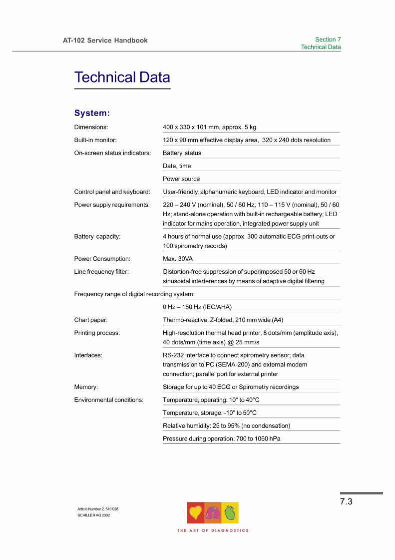
7.3Article Number 2. 540 028
SCHILLER AG 2002
AT-102 Service Handbook Section 7Technical Data
Technical Data
System:
Dimensions: 400 x 330 x 101 mm, approx. 5 kg
Built-in monitor: 120 x 90 mm effective display area, 320 x 240 dots resolution
On-screen status indicators: Battery status
Date, time
Power source
Control panel and keyboard: User-friendly, alphanumeric keyboard, LED indicator and monitor
Power supply requirements: 220 – 240 V (nominal), 50 / 60 Hz; 110 – 115 V (nominal), 50 / 60
Hz; stand-alone operation with built-in rechargeable battery; LED
indicator for mains operation, integrated power supply unit
Battery capacity: 4 hours of normal use (approx. 300 automatic ECG print-outs or
100 spirometry records)
Power Consumption: Max. 30VA
Line frequency filter: Distortion-free suppression of superimposed 50 or 60 Hz
sinusoidal interferences by means of adaptive digital filtering
Frequency range of digital recording system:
0 Hz – 150 Hz (IEC/AHA)
Chart paper: Thermo-reactive, Z-folded, 210 mm wide (A4)
Printing process: High-resolution thermal head printer, 8 dots/mm (amplitude axis),
40 dots/mm (time axis) @ 25 mm/s
Interfaces: RS-232 interface to connect spirometry sensor; data
transmission to PC (SEMA-200) and external modem
connection; parallel port for external printer
Memory: Storage for up to 40 ECG or Spirometry recordings
Environmental conditions: Temperature, operating: 10° to 40°C
Temperature, storage: -10° to 50°C
Relative humidity: 25 to 95% (no condensation)
Pressure during operation: 700 to 1060 hPa

7.4
AT-102 Service Handbook
Technical Data
Safety Standards:
Safety standard: CF according IEC 60601-1 and
IEC 601-2-25
Protection class: I according to IEC 60601-1 (with internal battery), IIa according to
EEC directive 93/42 (medical protection class)
Conformity: CE according to 93/42/EEC
Technical Data for ECG:
Patient input circuit: Fully floating and isolated, defibrillation-protected (only with
original SCHILLER patient cable)
Monitor display: 3-channel display of the selected leads
25, 50 mm/s
5, 10, 20 mm/mV
Filter status (on/off)
Insufficient electrode contact
Heart Frequency, HF
mm/mv, mm/s
Leads: 12 simultaneous leads: Standard / Cabrera
Chart print-out speed: 5/10/25/50 mm/s (manual print)
Sensitivities: 5/10/20 mm/m, either automatically adjusted or manually
selected
Automatic lead programs: 6/12-channel presentations of 12 simultaneously recorded
standard leads on one or more A4 pages
Numerous print-out formats can be selected
Data record: Patient data (name, age, height, weight, BP), user ID
Listing of all ECG recording conditions (date, time, filter)
With optional interpretation (C) program: ECG measurements
results (intervals, amplitudes, electrical axes), average
complexes with optional measurement reference markings,
guidance on interpreting adult and paediatric ECGs

7.5Article Number 2. 540 028
SCHILLER AG 2002
AT-102 Service Handbook Section 7Technical Data
Technical Data
Recording track: 6/12-channel presentation, optimal positioning on a width of 200
mm, automatic baseline adjustment
Filter: Myogram filter (muscle tremor filter): 25 Hz or 35 Hz, can be
switched on/off
ECG amplifier: Simultaneous recording of all 9 active electrode signals (= 12
leads)
Sampling frequency: 1000 Hz
Pacemaker detection: > + 2 mV/> 0.1 ms
Technical Data for Spirometry (Option):
Measured values: FVC: FVC, FEV0.5, FEV1.0, FEV3.0, FEV0.5/FVC, FEV1,0/FVC,
FEV3.0/FVC, FEF0.2-1.2, FEF25-75%, FEF75-85%, PEF, FEF25%, FEF50%,
FEF75%, FIVC, FIV1.0 , FIV1.0/FIVC, FIV1.0/FVC, PIF, FIF50%, FMFT,
SVC: SVC, ERV, IRV, TV,
MVV: MVV, RR, TV
Presentation possibilities (print-out and screen):
Flow/volume graph
Volume/time graph
Table of measured values
Realtime flow curve
Data record: Patient data (name, age, height, weight), user ID
Registration conditions (date, time, date of last calibration)
Flow/volume graph and/or volume/time graph
Table of measured values with PREDICTED/ACTUAL/
DIFFERENTIAL values
Diagnosis guidance
Prediction equations: Adults: ECCS, Austria, Crapo, Morris, Knudson, Knudson76,
Polgar, Berglund, Finland, India, Composite
Children: Quanjer & Tammeling, Austria, India, Knudson,
Knudson76, Polgar
Extrapolated predicted values
Comparison of PRE/POST medication is possible
Standards Compliance: ATS, OSHA, NIOSH

7.6
AT-102 Service Handbook
Technical Data
SPIROVIT SP-250 Pneumotach Flow sensor for pulmonary function testing with disposable
mouthpiece:
Dimensions of SP-250: 118 x 36 x 28 mm, approx. 120 g;
4.6 x 1.4 x 1.1 in., approx. 0.26 Ibs
Measuring method: Pneumotachometer
Measuring accuracy: According ATS < 3%
Flow impedance: < 0.2 mbar*s/l at 12 l/s
SPIROVIT SP-260 Pneumotach Flow sensor for pulmonary function testing with
reusable mouthpiece:
Dimensions of SP-260: 125 x 36 x 28 mm, approx. 160 g;
4.9 x 1.4 x 1.1 in., approx. 0.34 Ibs
Measuring method, Measuring accuracy, Flow impedance same
as SP-250
Delivered: 1 pneumotach sensor; choice of SP-250 disposable
(P/N 2.100022) or SP-260 reusable sensor (P/N 2.100551)
Accessories: 2 nose clips and either 1 pack of disposable plastic
mouthpieces for SP-250 (P/N 2.100077) or 1 pack of disposable
filters for SP-260 (P/N 2.100123)
1 operating manual

7.7Article Number 2. 540 028
SCHILLER AG 2002
AT-102 Service Handbook Section 7Technical Data
Technical Data
Standard
CARDIOVIT AT-102 ECG with 12 simultaneous leads, pacemaker detection, automatic ECG
measurement.
Accessories: 1 10-lead patient cable
1 set of electrodes or disposable electrodes
1 power cable
1 pack chart paper
Operating manual
Software options: SEMA-200 PC software to save, validate and achive ECG and
spirometry data on PC
Hardware options: Equipment trolley
Spirometry sensor SP-250 or SP-260
Calibration syringe
Vacuum electrode system VAC-100
External printer
Configurations
The CARDIOVIT AT-102 is available in three versions:
Version M - Standard: Unit with ECG recording, measurements, memory and printout
capabilities.
Version C - Interpretation: Standard unit with ECG Interpretation program
Version S - Stress: C unit with ECG stress test program
Note The spirometry option, using the SP-250 sensor or SP-260 sensor, is available when the
sensor is connected to the RS-232 interface.
Technical data subject to change without notice.

7.8
AT-102 Service Handbook

AnnexA.1Article Number 2. 540 028
SCHILLER AG 2002
AT-102 Service Handbook Annex AGlossary
Annex A
Glossary

AnnexA.2
AT-102 Service Handbook
Introduction
The following list provides a glossary of the important signals and acronyms used in the circuit
diagrams for the SCHILLER instruments. They will not all apply to the AT-102
Only abbreviations that are specific to SCHILLER equipment are included here. General
electrical and electronic abbreviations are not included.

AnnexA.3Article Number 2. 540 028
SCHILLER AG 2002
AT-102 Service Handbook Annex AGlossary
Acronyms
..OS Offset signal (on the ECG amplifier).
A(1...n) CPU Address Bus
ALBEEP(or BEEP) Alarm beeper signal to the audio amplifier. The frequency of this signal is about
1000 Hz.
ANA1, ANA2 Analog input from the experimental inputs DC1 and DC2
AS Address strobe
BATT Signal to CPU indicating battery operation
BATTLC Analog signal to the processor giving the charge condition of the battery.
BATTV Battery voltage - analog signal from the power supply used by the processor to
assess battery or mains operation.
BLOW Battery less than 11.3 V. LCD flashes when this signal is active. When the
battery drops to below approximately 9.4 V the unit is switched off. These values
apply to equipment with 12 V battery. For other equipment the limits are different.
CHAD.. ECG signal multiplexer control signals (on the ECG amplifier).
CIF(0..16) Communication interface. General control signals for the communications
interface circuits.
CI(0..10) RS interface control lines - input.
CO(0..10) RS interface control lines - output.
CL1 19 kHz LCD latch pulse.
CL2 3.11 MHz LCD clock frequency.
CLK.. Clock signal. The number following the CLK indicates the frequency. For example
CLK19 indicates a frequency of 19 MHz.
CS.. Chip select. The general format of the chip select signals is CS followed by some
characters. The characters indicate the device to which the chip select signal
appertains. For example CSRTC is the chip select signal for the real time clock
and CSEPROM is the select signal for the EPROM etc.
CTS Clear to send. General signal used in data communication.
D(0..15) Data bus.
DACWR Digital / analog converter write.
DMUX Data multiplexer.
DRAM Dynamic RAM.
DRC(0..6) Dynamic RAM control.

AnnexA.4
AT-102 Service Handbook
DS.. Data strobe.
DSP.. Digital signal processor (on program pack).
DTACK Transfer data acknowledge. Bus signal to acknowledge transfer of data.
DTR Outgoing serial data, turns modem ON.
ECGI ECG in - serial ECG data to the CPU sent over the optical interface.
ECGMUX The multiplexed ECG signal from the ECG amplifier.
ECGO ECG out - serial ECG amplifier control data from the CPU sent over the optical
interface.
EF Empty flag.
EJCT Eject (paper tray).
EKGRES Reset signal to the ECG amplifier. This signal resets the ECG amplifier to
recenter the ECG image on the LCD.
FIFOR First in first out read
FLM Control signal for frame synchronisation of the LCD.
FPIN Input for floating point co-processor.
FWR Flag read / write.
HREN Output enable signal for thermal print head data (History enable).
HSYNC Horizontal synchronisation (video / VGA output).
IPL0..2 Interrupt priority level (binary encoded).
IREG Control signal from the current detector and limiter circuit on the power supply to
regulate supply.
ISYS Interrupt system (2 kHz).
KB.. Keyboard data in.
KBBEEP Keyboard beep (to audio amplifier).
KBCLR Keyboard clear.
KBCL1 Keyboard clock.
KBCL2 Keyboard clock.
KBIN Keyboard data in - serial data from the keyboard to the CPU.
KBS.. Keyboard strobe.
KONV Convert - this signal initiates the conversion of the incoming signal from the ECG
amplifier.
LA Left arm.
LEDB Battery LED.

AnnexA.5Article Number 2. 540 028
SCHILLER AG 2002
AT-102 Service Handbook Annex AGlossary
LEDMAINS Signal indicating mains connected to operate LED indicator on the keyboard.
LCA Liquid crystal address - enable.
LCD KONT LCD contrast - sets the -18 V voltage level (from which the LCD backlight power is
generated) and thus the contrast of the screen.
LD1,2,3,4 Lower LCD data.
LDS Lower data strobe.
LOE Lower output enable.
LP Line synchronisation.
LSRAM Lower output enable - control signal for static RAM.
LWE Lower write enable.
M LCD control signal derived from FLM.
MCLK Motor clock - speed control for the printer motor.
MOD Control signal from the battery charging circuit.
MOFF Motor off.
MON Motor ON - printer motor enable signal.
NWTZ Mains supply.
NMI Non-maskable interrupt activated by the reset button.
OFF Off signal from the OFF key to switch off the power supply.
PDS Control signal derived from FLM (unity waveform 1/2 FLM frequency).
PM Paper mark signal.
PMARK Paper mark detection signal.
PMPON Pacemaker detection pulse.
PMNEG Pacemaker negative - indicates the trailing edge of a pacemaker pulse.
PMPOS Pacemaker positive - indicates the leading edge of a pacemaker pulse.
QTRRG QRS trigger - output signal.
RA Right arm.
RAS Row address strobe.
RES\p Error reset signal to inactivate the LCD.
RTS Ready to send - outgoing serial data, handshake with CTS.
RXD Receive data - incoming serial data.
R / W Read / Write
RES Reset.
RESLCD/ Resets / darkens the LCD.

AnnexA.6
AT-102 Service Handbook
SC(0..8) System control bus - CPU control signals
SCINV Screen inversion.
SO Serial output from the CPU to the ECG amplifier via opto isolators.
SP.. Spirometry control and data signals.
SRAM Static RAM memory.
STRB1/2 Timing signals for printer control.
SYSEN System enable - active when the Program Pack is inserted. The CPU will not work if
this signal is not active.
TGATE Gate pulse for programmable timer. This signal sets the TPDUR signal.
TM Thermal printer temperature - dc voltage from the print head, pulse width modulation
of signal TPTH.
TPC Thermal printer clock. This is not a continuous clock signal but is active when
loading a line of printer data (into shift registers).
TPCLK Thermal printer clock.
TPD Thermal printer data - serial data for the printer.
TPDUR Thermal printer duration - duration of the strobe pulse dependant on the ambient
temperature of the print head and the resistance of the print head.
TPCSEL Thermal printer controller select - control of thermal printer FIFO (input memory
buffer).
TPL Thermal printer latch - print strobe control and data latch signal.
TPRES Thermal printer reset - FIFO reset for thermal printer controller.
TPS 0 & 1 Thermal printer strobe.
TPTH Thermal printer temperature - dc voltage from the print head to ADC, approximately
3.7 V at room temperature.
TS Temperature sense (from battery).
TXD Outgoing serial data.
uPOFF Off control signal. Logic 1 keeps the unit switched on, logic 0 switches the unit off.
Note that the unit is initially switched on directly from the ON key on the keyboard.
U1,2,3,4 Upper LCD data.
+UB Battery voltage.
UCAS Upper column address strobe (for dynamic RAM).
UD1, UD2 Upper data strobe - used for generating UOE and UWE.
UDS Upper data strobe - used on the Schiller gate array.
UOE, USRAM Upper output enable - for static RAM.
+UP Voltage rectified from the mains input and regulated to approximately +15 V.

AnnexA.7Article Number 2. 540 028
SCHILLER AG 2002
AT-102 Service Handbook Annex AGlossary
UWE Upper write enable.
+U Unregulated dc supply from mains (approximately 30V).
+UBU Back-up voltage for the real time clock and static RAM.
+UD Unswitched regulated dc voltage used as power source for the switched
supply +US. The voltage is 13.5 V when mains is connected, or battery
voltage when mains is not connected. When mains is connected, this supply
charges the battery.
-ULCD Contrast voltage to LCD.
+US Input voltage for all PSUs on the power supply board from the rectified mains
or from the battery.
VCC +5 V
VMA Valid memory address.
VPA Valid peripheral address.
VSYNC Vertical synchronisation - (video / VGA output).
WP0 and WP1 ECG in - the serial multiplexed ECG serial data to the CPU sent over the
optical interface, from the ECG amplifier.
XD0..XD3 Pixel information.
XSCL Shift clock for XDn.
YD Frame synchronisation.
YDIS/ LCD off.
ZEROSET Baseline reset (on the ECG amplifier) from the processor.

AnnexA.8
AT-102 Service Handbook

Annex BCircuit Diagrams and Engineering Drawings
AT-102 User Guide
Article Number 2. 540 028
SCHILLER AG 2002
AnnexB.1
Annex B
AT-102 Circuit Diagrams andEngineering Drawings

Index.1Article Number 2. 540 028
SCHILLER AG 2002
AT-102 Service HandbookIndex
Index

Index.2
AT-102 Service Handbook
Index
Symbols+2V, -2V and PWM Ramp Time Adjustment
5.10
AArticle Number iiAssociated Documents iiAuto-Centering 1.18Average Cycles 1.14
BBack Panel 1.5Baseline filter 1.15Battery Care xiBattery Charge Voltage 5.7Battery Pack 4.16Baudrate 1.28Bicycle Protocols 1.24Blood Pressure Entry 1.21Board Removal 4.12Board Replacement 4.13Bruce 1.24
CCabrera 1.18Calib 5.13Changing a Mains Fuse 1.7Check Procedures 3.2Communications Test 1.32Component Location ECG Amplifier 5.11Configurations 7.7Contents ivCustomer Services
Sales Department 6.2
DDate and Time 1.26Default Settings 1.33Default Test Protocol 1.22Defining / Editing Exercise Protocols 1.23Disposal Instructions xi
EECG Amplifier Adjustments 5.10ECG Amplifier Reference Voltage 5.11ECG Isolated Power Supplies 2.5ECG Printout 1.13ECG Recording Screens 1.3ECG Signal 2.6Electrode DC Offset 5.13ERGO Device 1.21Exploded View Base 4.6Exploded View Paper Feed 4.7External Connections - Back Panel 1.5External Modem 2.6
FFactory programmed Protocols 1.24Features 1.2Function icons 1.3
GGeneral Settings 1.21Getting Started 1.1

Index.3Article Number 2. 540 028
SCHILLER AG 2002
AT-102 Service HandbookIndex
IInitiating Functions or Tasks 1.3Installing New Software Options 5.14Installing New Software Options (Upgrade)
5.14Intended Use iiiInterpretation 1.14Interpretation Settings 1.17
KKeyboard 2.7, 4.17Keypad 1.8
LLanguage 1.27LCD 2.7LCD Display 1.4, 1.10Lead group settings 1.19Lead Sequence 1.18Left Posterior 1.19
MMain Components of the AT-102 1.4Mains filter 1.16Markings 1.14Measurements, Markings and Interpretation
1.14MK 14-10 Adjustment Locations 5.6Mode 1.28Motor Speed 2.5Myogram filter 1.16
NNehb 1.19Noise Damping 2.6
OObtaining a printout of all current settings
1.30Opening the Case 4.8, 4.10Operating Philosophy 1.3Ordering Information 6.2
PPaper Mark 2.5Paper Mark Detector Adjustment 5.8, 5.9Patient Cable Resistance 5.13Phone No 1.28Physical Overview 4.5Physicians`s Responsibility iiiPosterior 1.19Potential Equalisation 1.7Power Indicator symbol 1.6Power On Reset 2.5Power Supply 1.6Precordials 1.19Print Head Alignment and Print Head
Tension 3.14Printer 4.15Printer Timing 2.5Printout of all current settings 1.30Program Memory 2.4Proprietary Test Equipment/tools 5.5PWM Ramp Time Adjustment 5.10
RRecycling xiReference +2V, -2V Adjustment 5.10Removal and replacement 4.15Rhythm Lead Group 1.19Rhythm Leads 1.14Right Precordials 1.19RS-232 Interface 3.15RS-232 Test 3.14

Index.4
AT-102 Service Handbook
SSafety Notices xii, xiii, xivSafety Standards 7.4SCHILLER SSF 1.16Selecting the ERGO Device 1.21Sequential 1.18Service Printout 5.12, 5.13Signals 1.18Simultaneous 1.18Smoothing Filter 1.16software 5.14, 5.15, 5.16, 5.17Spare Parts 6.3Spiro Sensor Check 3.15Spiro sensor type 3.15Spirometry 7.5ST Amplitude Lead 1.22Stage Printout Format 1.22Standard 7.7Stepper Motor Controller 2.5Stress Settings 1.20Switching On and Off 1.6System 7.3System Option 5.14, 5.15, 5.16, 5.17System Settings 1.25
TTerms of Warranty xTest Equipment 5.5Thermal Print Head Controller 2.4Tools 4.8Top Assembly Removal 4.9Top Assembly Replacement 4.11Treadmill Protocols 1.24
UUdif 5.13Unit Defaults 1.34Uoff 5.13Upgrade 1.32, 5.14Upgrading the System Options and Updating software
5.14, 5.15Uref + 5.13Uref - 5.13User Identification (User ID) 1.26
WWarranty x

Index.5Article Number 2. 540 028
SCHILLER AG 2002
AT-102 Service HandbookIndex


![SUSTAINABILITY Report Bunge South America 2018 · management, please contact us at sustentabilidade@bunge.com [102-53] presentation [102-10, 102-16] letter from the ceo about operating](https://img.pdfslide.us/doc/110x75/5f4cb99e56d0ed5c810ad4d7/sustainability-report-bunge-south-america-management-please-contact-us-at-sustentabilidadebungecom.jpg)

![PIANO CONCERTO IN F 2nd Movement for Clarinets · 102 102 102 102 102 102 102 102 102 102 102 10 44 [Title]](https://img.pdfslide.us/doc/110x75/5e3946b540eed0696e2e90d2/piano-concerto-in-f-2nd-movement-for-clarinets-102-102-102-102-102-102-102-102-102.jpg)