Embed Size (px)
Citation preview
Service and Repair Manual
Serial Number Range
Z®-60/37 DC from Z6016N-101 to Z6016N-599
from Z60N-600
This manual includes: Repair procedures Fault Codes Electrical and Hydraulic Schematics
Z®-60/37 FE
For detailed maintenance procedures, refer to the appropriate Maintenance Manual for your machine.
Part No. 1271125GT Rev A6 December 2018
Service and Repair Manual December 2018
Introduction
ii Z®-60/37 DC • Z®-60/37 FE Part No. 1271125GT
Intr oducti on Intr oducti on
Important Read, understand and obey the safety rules and operating instructions in the appropriate Operator's Manual on your machine before attempting any procedure.
This manual provides troubleshooting and repair procedures for qualified service professionals.
Basic mechanical, hydraulic and electrical skills are required to perform most procedures. However, several procedures require specialized skills, tools, lifting equipment and a suitable workshop. In these instances, we strongly recommend that maintenance and repair be performed at an authorized Genie dealer service center.
Compliance
Machine Classification Group B/Type 3 as defined by ISO 16368
Machine Design Life Unrestricted with proper operation, inspection and scheduled maintenance.
Technical Publications Genie has endeavored to deliver the highest degree of accuracy possible. However, continuous improvement of our products is a Genie policy. Therefore, product specifications are subject to change without notice.
Readers are encouraged to notify Genie of errors and send in suggestions for improvement. All communications will be carefully considered for future printings of this and all other manuals.
Contact Us: Internet: www.genielift.com E-mail: [email protected]
Find a Manual for this Model Go to http://www.genielift.com
Use the links to locate Service Manuals, Maintenance Manuals, Service and Repair Manuals, Parts Manuals and Operator's Manuals.
Copyright © 2016 by Terex Corporation
1271125GT Rev A, April 2016
First Edition, First Printing
Genie and “Z” are registered trademarks of Terex South Dakota, Inc. in the U.S.A. and many other countries.
December 2018 Service and Repair Manual
Introduction
Part No. 1271125GT Z®-60/37 DC • Z®-60/37 FE iii
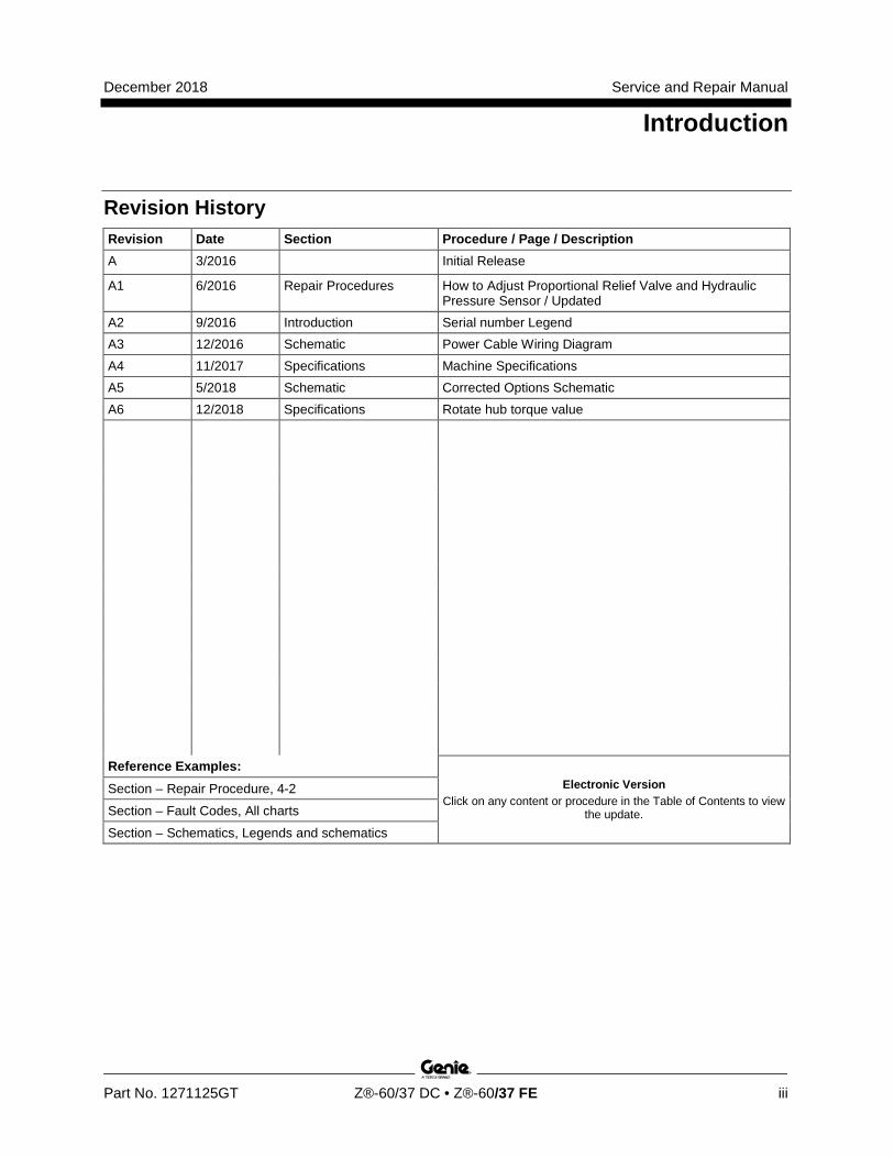
Revision History Revision Date Section Procedure / Page / Description A 3/2016 Initial Release
A1 6/2016 Repair Procedures How to Adjust Proportional Relief Valve and Hydraulic Pressure Sensor / Updated
A2 9/2016 Introduction Serial number Legend A3 12/2016 Schematic Power Cable Wiring Diagram A4 11/2017 Specifications Machine Specifications A5 5/2018 Schematic Corrected Options Schematic A6 12/2018 Specifications Rotate hub torque value
Reference Examples: Electronic Version
Click on any content or procedure in the Table of Contents to view the update.
Section – Repair Procedure, 4-2
Section – Fault Codes, All charts
Section – Schematics, Legends and schematics
Service and Repair Manual December 2018
Introduction
iv Z®-60/37 DC • Z®-60/37 FE Part No. 1271125GT
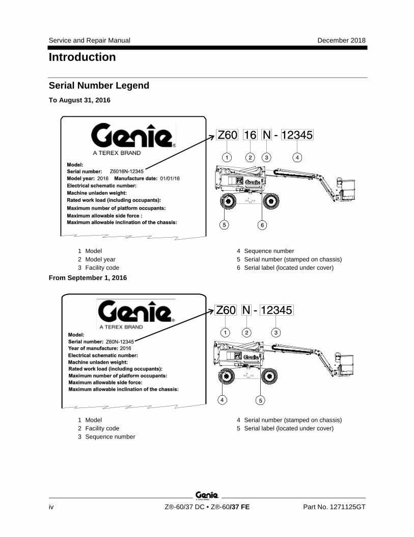
Serial Number Legend To August 31, 2016
1 Model 2 Model year 3 Facility code
4 Sequence number 5 Serial number (stamped on chassis) 6 Serial label (located under cover)
From September 1, 2016
1 Model 2 Facility code 3 Sequence number
4 Serial number (stamped on chassis) 5 Serial label (located under cover)
December 2018 Service and Repair Manual
Safety Rules
Part No. 1271125GT Z®-60/37 DC • Z®-60/37 FE v
Section 1 Safety R ules
Danger Failure to obey the instructions and safety rules in this manual and the appropriate Operator's Manual on your machine will result in death or serious injury.
Many of the hazards identified in the operator's manual are also safety hazards when maintenance and repair procedures are performed.
Do Not Perform Maintenance Unless: R You are trained and qualified to perform
maintenance on this machine.
R You read, understand and obey:
· manufacturer's instructions and safety rules
· employer's safety rules and worksite regulations
· applicable governmental regulations
R You have the appropriate tools, lifting equipment and a suitable workshop.
Service and Repair Manual December 2018
Safety Rules
vi Z®-60/37 DC • Z®-60/37 FE Part No. 1271125GT
Personal Safety Any person working on or around a machine must be aware of all known safety hazards. Personal safety and the continued safe operation of the machine should be your top priority.
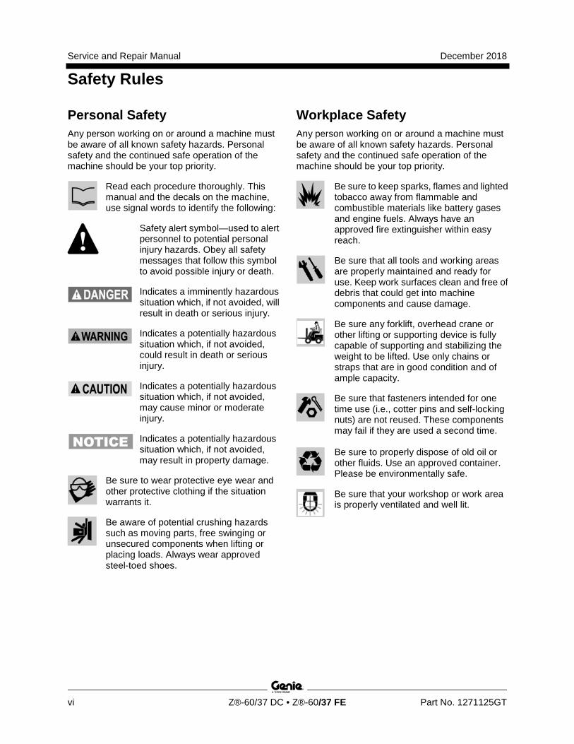
Read each procedure thoroughly. This manual and the decals on the machine, use signal words to identify the following:
Safety alert symbol—used to alert personnel to potential personal injury hazards. Obey all safety messages that follow this symbol to avoid possible injury or death.
Indicates a imminently hazardous situation which, if not avoided, will result in death or serious injury.
Indicates a potentially hazardous situation which, if not avoided, could result in death or serious injury.
Indicates a potentially hazardous situation which, if not avoided, may cause minor or moderate injury.
Indicates a potentially hazardous situation which, if not avoided, may result in property damage.
Be sure to wear protective eye wear and other protective clothing if the situation warrants it.
Be aware of potential crushing hazards such as moving parts, free swinging or unsecured components when lifting or placing loads. Always wear approved steel-toed shoes.
Workplace Safety Any person working on or around a machine must be aware of all known safety hazards. Personal safety and the continued safe operation of the machine should be your top priority.
Be sure to keep sparks, flames and lighted tobacco away from flammable and combustible materials like battery gases and engine fuels. Always have an approved fire extinguisher within easy reach.
Be sure that all tools and working areas are properly maintained and ready for use. Keep work surfaces clean and free of debris that could get into machine components and cause damage.
Be sure any forklift, overhead crane or other lifting or supporting device is fully capable of supporting and stabilizing the weight to be lifted. Use only chains or straps that are in good condition and of ample capacity.
Be sure that fasteners intended for one time use (i.e., cotter pins and self-locking nuts) are not reused. These components may fail if they are used a second time.
Be sure to properly dispose of old oil or other fluids. Use an approved container. Please be environmentally safe.
Be sure that your workshop or work area is properly ventilated and well lit.
December 2018
Table of Contents
Part No. 1271125GT Z®-60/37 DC • Z®-60/37 FE vii
Introduction Introduction ........................................................................................................... ii Important Information ............................................................................................. ii Find a Manual for this Model .................................................................................. ii
Serial Number Legend .......................................................................................... iv
Section 1 Safety Rules .......................................................................................................... v General Safety Rules ............................................................................................. v
Section 2 Specifications ....................................................................................................... 1 Machine Specifications ........................................................................................... 1
Performance Specifications .................................................................................... 2
Hydraulic Specification ........................................................................................... 2
Hydraulic Component Specifications...................................................................... 5
Manifold Component Specifications ....................................................................... 6 Kubota D1105 Engine Specifications ..................................................................... 7
Machine Torque Specifications .............................................................................. 8
Machine Component Weights ................................................................................ 8
Hydraulic Hose and Fitting Torque Specifications ................................................. 9
Torque Procedure ................................................................................................ 10
December 2018
Table of Contents
viii Z®-60/37 DC • Z®-60/37 FE Part No. 1271125GT
Section 3 Repair Procedures ............................................................................................. 12 Introduction .......................................................................................................... 12
Cailbration Process Steps .................................................................................... 14
Platform Controls ............................................................................................... 15 1-1 Platform Controls ........................................................................................... 15
How to Adjust the Joystick Threshold Setting ................................................ 16
How to Adjust the Joystick Max-out Setting ................................................... 17
How to Adjust the Joystick Ramp Rate Setting .............................................. 20
1-2 How to Calibrate Booms Angle Sensors ....................................................... 21
1-3 How to Clear the Fault History ....................................................................... 22
Platform Components ....................................................................................... 22 2-1 Platform Leveling Slave Cylinder ................................................................... 22
2-2 Platform Rotator ............................................................................................. 24
2-3 Platform Overload System ............................................................................. 25
2-4 How to Reset Overload Recovery Message .................................................. 27
Jib Boom Components ...................................................................................... 28 3-1 Jib Boom ........................................................................................................ 28 3-2 Jib Boom Lift Cylinder .................................................................................... 29
Primary Boom Components ............................................................................. 30 4-1 Cable Track.................................................................................................... 30
How to Repair the Cable Track....................................................................... 31
4-2 Primary Boom ................................................................................................ 31
How to Disassemble the Primary Boom ......................................................... 32 4-3 Primary Boom Lift Cylinder ............................................................................ 33
4-4 Primary Boom Extension Cylinder ................................................................. 34
4-5 Platform Leveling Master Cylinder ................................................................. 35
December 2018
Table of Contents
Part No. 1271125GT Z®-60/37 DC • Z®-60/37 FE ix
Secondary Boom Components ......................................................................... 36 5-1 Secondary Boom Lift Cylinder ........................................................................ 37
Engines ................................................................................................................ 39 6-1 RPM Adjustment ............................................................................................ 39
How to Replace the Motor Tach Sensor ......................................................... 39
Hydraulic Pumps ................................................................................................ 40 7-1 Function Pump ............................................................................................... 40
How to Check the Function Pump Calibration ................................................ 41
Manifolds ............................................................................................................. 42 8-1 Function Manifold Components ..................................................................... 42
8-2 Valve Adjustments - Function Manifold .......................................................... 47
How to Adjust the Proportional Relief Valve and Hydraulic Pressure Sensor 47
How to Adjust the Platform Level Up Relief Valve .......................................... 48
How to Adjust the Primary Boom Extend Relief Valve.................................... 49
8-3 Jib Boom / Platform Rotate Manifold Components ........................................ 50 8-4 Turntable Rotation Manifold Components ..................................................... 51
8-5 Oscillate Directional Valve Manifold Components ......................................... 52
8-6 How to Set Up the Oscillate Directional Valve ............................................... 53
How to Adjust the Oscillate Reducing Valve ................................................... 53
How to Test a Coil Diode ................................................................................ 55
Turntable Rotation Components ...................................................................... 56 9-1 Turntable Rotation Assembly ......................................................................... 56
9-2 How to Replace the Universal Tilt Sensor ..................................................... 58
How to Calibrate the Universal Tilt Sensor ..................................................... 59
Axle Components ............................................................................................... 60 10-1 Oscillating Axle Cylinders ............................................................................. 60
10-2 How to Remove the Steer Cylinder .............................................................. 61 How to Calibrate the Steer Angle Sensor ....................................................... 61
December 2018
Table of Contents
x Z®-60/37 DC • Z®-60/37 FE Part No. 1271125GT
Section 4 Fault Codes ......................................................................................................... 63 Introduction .......................................................................................................... 63
Control System Fault Codes ............................................................................. 64 Fault Codes Ground Controls .............................................................................. 64
How to Retrieve Control System Fault Codes - Platform Controls ...................... 65 Control System Fault Codes ................................................................................ 66
Section 5 Navigation Menus .............................................................................................. 81 Faults Navigation Menu ....................................................................................... 82
Options Navigation Menu ..................................................................................... 83
Settings Navigation Menu .................................................................................... 84
Section 6 Schematics ......................................................................................................... 85 Introduction .......................................................................................................... 85
Electrical Symbol Legend .................................................................................... 86
Hydraulic Symbols Legend .................................................................................. 87
Electrical Component and Wire Color Legends ................................................... 88 Kubota Engine Fuse and Relay Module .............................................................. 91
12V DC Charger Wiring (DC Option) ................................................................... 92
AC Input Wiring (DC Option) ................................................................................ 93
CAN BUS Wiring Diagram - DC Models .............................................................. 94
Limit Switch/Angle Sensor Legend ...................................................................... 95
Electrical Schematics – Options ...................................................................... 97 Wiring Diagram - Options .................................................................................... 98
Schematics - Options, 4WD, DC, and FE Models ............................................... 99
Power Cable Wiring Diagram ............................................................................. 102
Hydraulic Schematics ...................................................................................... 103 Hydraulic Schematic - DC and FE Models ........................................................ 104
Electrical Schematics ...................................................................................... 105 Electrical Schematics, DC/FE Models ............................................................... 106
Ground Control Box Terminal Strip Wiring Diagram .......................................... 112
Platform Control Box Wiring Diagram ................................................................ 113
December 2018 Service and Repair Manual
Specifications
Part No. 1271125GT Z®-60/37 DC • Z®-60/37 FE 1
Section 2 Specificati ons
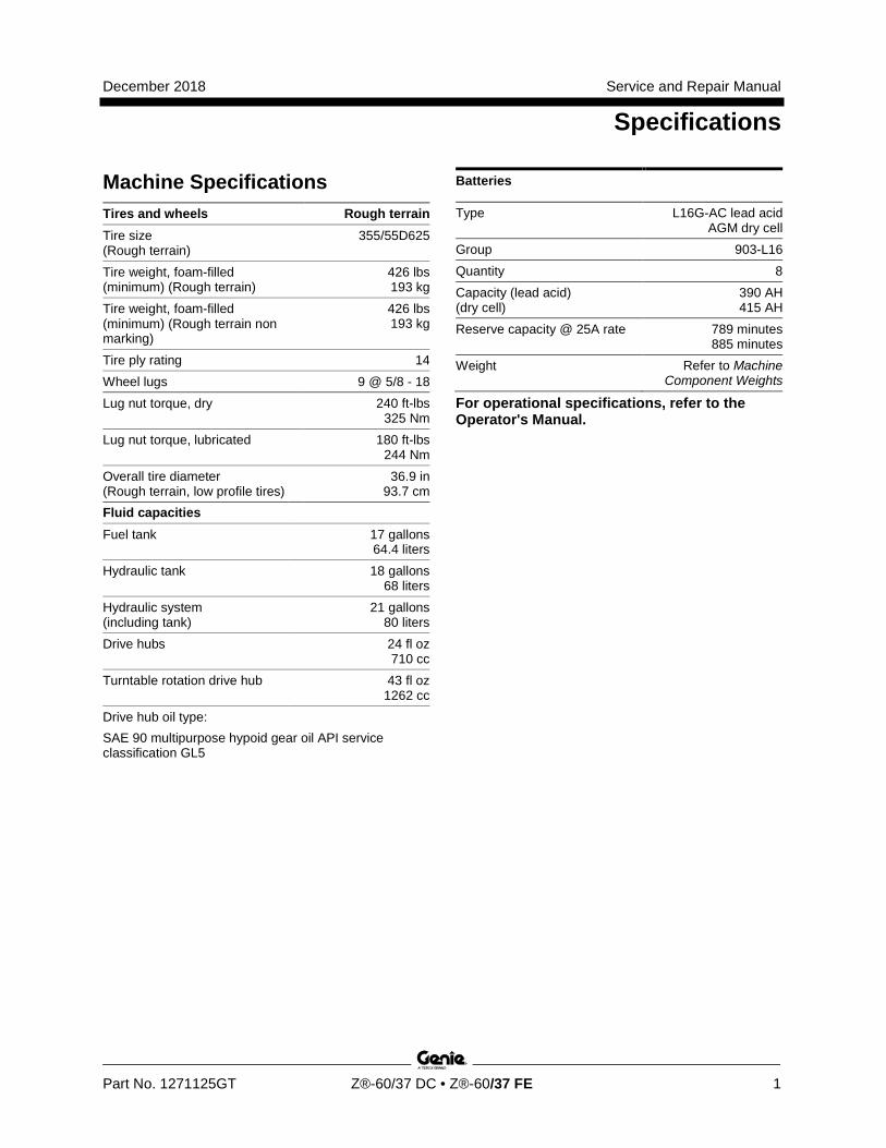
Machine Specifications Tires and wheels Rough terrain Tire size (Rough terrain)
355/55D625
Tire weight, foam-filled (minimum) (Rough terrain)
426 lbs 193 kg
Tire weight, foam-filled (minimum) (Rough terrain non marking)
426 lbs 193 kg
Tire ply rating 14 Wheel lugs 9 @ 5/8 - 18 Lug nut torque, dry 240 ft-lbs
325 Nm Lug nut torque, lubricated 180 ft-lbs
244 Nm Overall tire diameter (Rough terrain, low profile tires)
36.9 in 93.7 cm
Fluid capacities Fuel tank 17 gallons
64.4 liters Hydraulic tank 18 gallons
68 liters Hydraulic system (including tank)
21 gallons 80 liters
Drive hubs 24 fl oz 710 cc
Turntable rotation drive hub 43 fl oz 1262 cc
Drive hub oil type: SAE 90 multipurpose hypoid gear oil API service classification GL5
Batteries
Type L16G-AC lead acid AGM dry cell
Group 903-L16 Quantity 8 Capacity (lead acid) (dry cell)
390 AH 415 AH
Reserve capacity @ 25A rate 789 minutes 885 minutes
Weight Refer to Machine Component Weights
For operational specifications, refer to the Operator's Manual.
Service and Repair Manual December 2018
Specifications
2 Z®-60/37 DC • Z®-60/37 FE Part No. 1271125GT
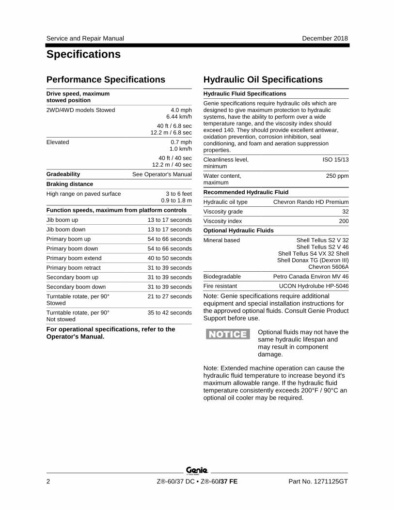
Performance Specifications Drive speed, maximum stowed position 2WD/4WD models Stowed 4.0 mph
6.44 km/h 40 ft / 6.8 sec
12.2 m / 6.8 sec Elevated 0.7 mph
1.0 km/h 40 ft / 40 sec
12.2 m / 40 sec Gradeability See Operator's Manual
Braking distance High range on paved surface 3 to 6 feet
0.9 to 1.8 m
Function speeds, maximum from platform controls Jib boom up 13 to 17 seconds Jib boom down 13 to 17 seconds Primary boom up 54 to 66 seconds Primary boom down 54 to 66 seconds Primary boom extend 40 to 50 seconds Primary boom retract 31 to 39 seconds Secondary boom up 31 to 39 seconds Secondary boom down 31 to 39 seconds Turntable rotate, per 90° Stowed
21 to 27 seconds
Turntable rotate, per 90° Not stowed
35 to 42 seconds
For operational specifications, refer to the Operator's Manual.
Hydraulic Oil Specifications Hydraulic Fluid Specifications Genie specifications require hydraulic oils which are designed to give maximum protection to hydraulic systems, have the ability to perform over a wide temperature range, and the viscosity index should exceed 140. They should provide excellent antiwear, oxidation prevention, corrosion inhibition, seal conditioning, and foam and aeration suppression properties. Cleanliness level, minimum
ISO 15/13
Water content, maximum
250 ppm
Recommended Hydraulic Fluid
Hydraulic oil type Chevron Rando HD Premium Viscosity grade 32 Viscosity index 200 Optional Hydraulic Fluids
Mineral based Shell Tellus S2 V 32 Shell Tellus S2 V 46
Shell Tellus S4 VX 32 Shell Shell Donax TG (Dexron III)
Chevron 5606A
Biodegradable Petro Canada Environ MV 46 Fire resistant UCON Hydrolube HP-5046
Note: Genie specifications require additional equipment and special installation instructions for the approved optional fluids. Consult Genie Product Support before use.
Optional fluids may not have the same hydraulic lifespan and may result in component damage.
Note: Extended machine operation can cause the hydraulic fluid temperature to increase beyond it's maximum allowable range. If the hydraulic fluid temperature consistently exceeds 200°F / 90°C an optional oil cooler may be required.
December 2018 Service and Repair Manual
Specifications
Part No. 1271125GT Z®-60/37 DC • Z®-60/37 FE 3
Do not top off with incompatible hydraulic fluids. Hydraulic fluids may be incompatible due to the differences in base additive chemistry. When incompatible fluids are mixed, insoluble materials may form and deposit in the hydraulic system, plugging hydraulic lines, filters, control valves and may result in component damage.
Note: Do not operate the machine when the ambient air temperature is consistently above 120°F / 49°C.
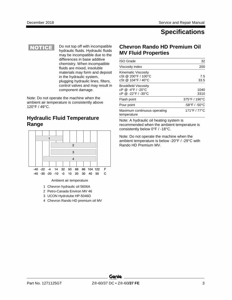
Hydraulic Fluid Temperature Range
Ambient air temperature
1 Chevron hydraulic oil 5606A 2 Petro-Canada Environ MV 46 3 UCON Hydrolube HP-5046D 4 Chevron Rando HD premium oil MV
Chevron Rando HD Premium Oil MV Fluid Properties ISO Grade 32 Viscosity index 200 Kinematic Viscosity cSt @ 200°F / 100°C cSt @ 104°F / 40°C
7.5
33.5 Brookfield Viscosity cP @ -4°F / -20°C cP @ -22°F / -30°C
1040 3310
Flash point 375°F / 190°C Pour point -58°F / -50°C Maximum continuous operating temperature
171°F / 77°C
Note: A hydraulic oil heating system is recommended when the ambient temperature is consistently below 0°F / -18°C.
Note: Do not operate the machine when the ambient temperature is below -20°F / -29°C with Rando HD Premium MV.
Service and Repair Manual December 2018
Specifications
4 Z®-60/37 DC • Z®-60/37 FE Part No. 1271125GT
Chevron 5606A Hydraulic Oil Fluid Properties ISO Grade 15 Viscosity index 300 Kinematic Viscosity cSt @ 200°F / 100°C cSt @ 104°F / 40°C cSt @ -40°F / -40°C
5.5
15.0 510
Flash point 180°F / 82°C Pour point -81°F / -63°C Maximum continuous operating temperature
124°F / 51°C
Note: Use of Chevron 5606A hydraulic fluid, or equivalent, is required when ambient temperatures are consistently below 0°F / -17°C unless an oil heating system is used.
Continued use of Chevron 5606A hydraulic fluid, or equivalent, when ambient temperatures are consistently above 32°F / 0°C may result in component damage
Petro-Canada Environ MV 46 Fluid Properties ISO Grade 46 Viscosity index 154 Kinematic Viscosity cSt @ 200°F / 100°C cSt @ 104°F / 40°C
8.0
44.4 Flash point 482°F / 250°C Pour point -49°F / -45°C Maximum continuous operating temperature
180°F / 82°C
Shell Tellus S4 VX Fluid Properties ISO Grade 32 Viscosity index 300 Kinematic Viscosity cSt @ 200°F / 100°C cSt @ 104°F / 40°C
9
33.8 Brookfield Viscosity cSt @ -4°F / -20°C cSt @ -13°F / -25°C cSt @ -40°F / -40°C
481
702.4 2624
Flash point >100 Pour point -76°F / -60°C Maximum continuous operating temperature
103°F / 75°C
December 2018 Service and Repair Manual
Specifications
Part No. 1271125GT Z®-60/37 DC • Z®-60/37 FE 5
UCON Hydrolube HP-5046 Fluid Properties ISO Grade 46 Viscosity index 192 Kinematic Viscosity cSt @ 149°F / 65°C cSt @ 104°F / 40°C cSt @ 0°F / -18°C
22 46
1300
Flash point None Pour point -81°F / -63°C Maximum continuous operating temperature
189°F / 87°C
Hydraulic Component Specifications Function pump Type 2 section tandem gear
pump
Displacement per revolution (inner pump) (outer pump)
.40 cu in / 6.6 cc
.20 cu in / 3.3 cc
Max flow rate L/min(inner pump) L/min(outer pump)
6.8 gpm / 25.74 3.4 gpm / 12.87
Auxiliary Pump Type Fixed displacement
gear pump Displacement per revolution 1.7 gpm
6.44 L/min
Function manifold Proportional relief valve pressure, variable
50 to 3000 psi 3.4 to 207 bar
Platform level relief valve pressure
2800 psi 193 bar
Primary boom extend relief valve pressure
1250 psi 86 bar
Oscillate reducing valve pressure 400 psi 28 bar
Platform level flow regulator Variable 1 to 1.5 gpm
3.8 to 5.7 L/min
Hydraulic Filters High pressure filter: Beta 5 ˆ 1000 Hydraulic tank return filter Beta 10 ˆ 200
Service and Repair Manual December 2018
Specifications
6 Z®-60/37 DC • Z®-60/37 FE Part No. 1271125GT
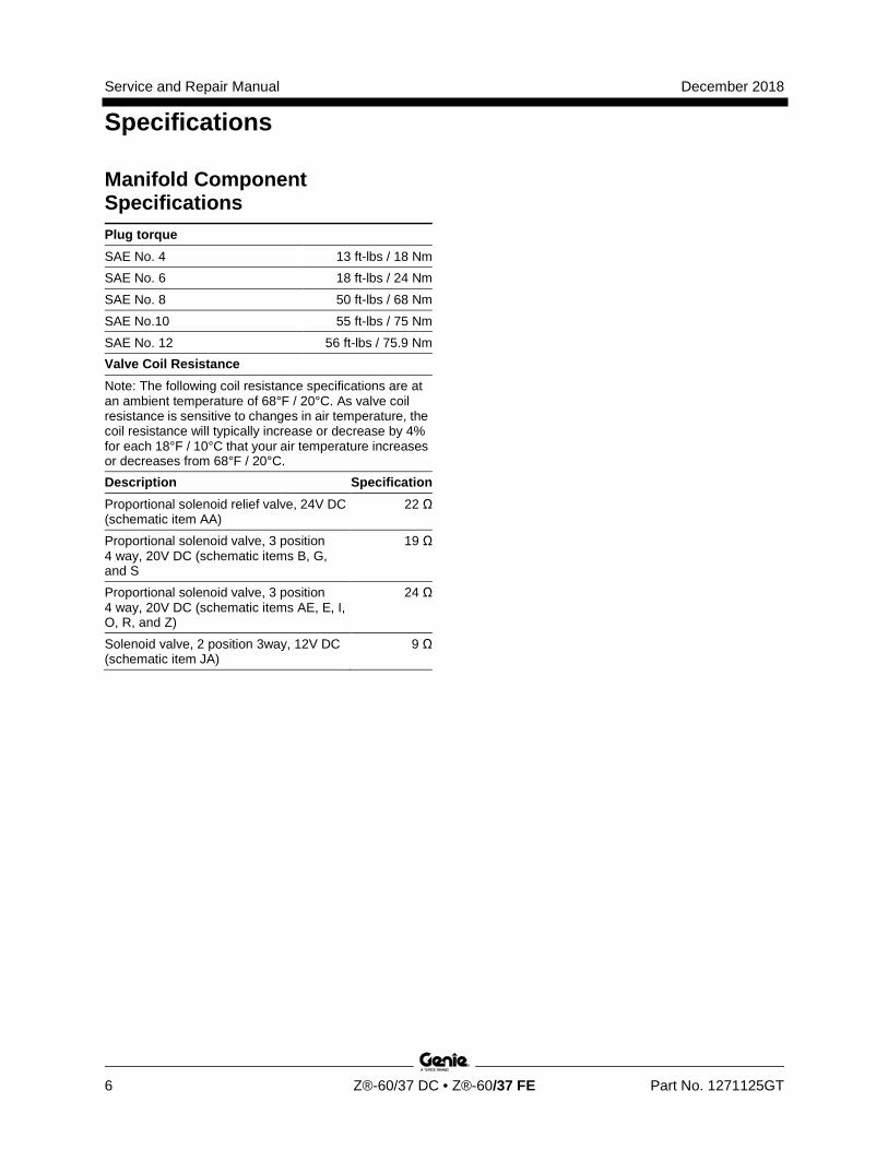
Manifold Component Specifications Plug torque SAE No. 4 13 ft-lbs / 18 Nm SAE No. 6 18 ft-lbs / 24 Nm SAE No. 8 50 ft-lbs / 68 Nm SAE No.10 55 ft-lbs / 75 Nm SAE No. 12 56 ft-lbs / 75.9 Nm Valve Coil Resistance Note: The following coil resistance specifications are at an ambient temperature of 68°F / 20°C. As valve coil resistance is sensitive to changes in air temperature, the coil resistance will typically increase or decrease by 4% for each 18°F / 10°C that your air temperature increases or decreases from 68°F / 20°C. Description Specification
Proportional solenoid relief valve, 24V DC (schematic item AA)
22 Ω
Proportional solenoid valve, 3 position 4 way, 20V DC (schematic items B, G, and S
19 Ω
Proportional solenoid valve, 3 position 4 way, 20V DC (schematic items AE, E, I, O, R, and Z)
24 Ω
Solenoid valve, 2 position 3way, 12V DC (schematic item JA)
9 Ω
December 2018 Service and Repair Manual
Specifications
Part No. 1271125GT Z®-60/37 DC • Z®-60/37 FE 7
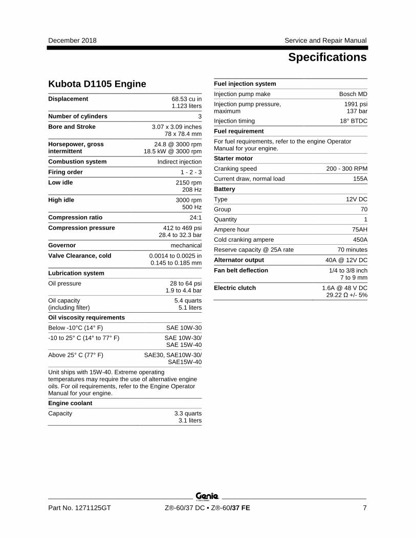
Kubota D1105 Engine Displacement 68.53 cu in
1.123 liters
Number of cylinders 3
Bore and Stroke 3.07 x 3.09 inches 78 x 78.4 mm
Horsepower, gross intermittent
24.8 @ 3000 rpm 18.5 kW @ 3000 rpm
Combustion system Indirect injection
Firing order 1 - 2 - 3
Low idle 2150 rpm 208 Hz
High idle 3000 rpm 500 Hz
Compression ratio 24:1
Compression pressure 412 to 469 psi 28.4 to 32.3 bar
Governor mechanical
Valve Clearance, cold 0.0014 to 0.0025 in 0.145 to 0.185 mm
Lubrication system Oil pressure 28 to 64 psi
1.9 to 4.4 bar Oil capacity (including filter)
5.4 quarts 5.1 liters
Oil viscosity requirements Below -10°C (14° F) SAE 10W-30 -10 to 25° C (14° to 77° F) SAE 10W-30/
SAE 15W-40
Above 25° C (77° F) SAE30, SAE10W-30/ SAE15W-40
Unit ships with 15W-40. Extreme operating temperatures may require the use of alternative engine oils. For oil requirements, refer to the Engine Operator Manual for your engine. Engine coolant Capacity 3.3 quarts
3.1 liters
Fuel injection system Injection pump make Bosch MD Injection pump pressure, maximum
1991 psi 137 bar
Injection timing 18° BTDC
Fuel requirement For fuel requirements, refer to the engine Operator Manual for your engine. Starter motor Cranking speed 200 - 300 RPM Current draw, normal load 155A
Battery Type 12V DC Group 70 Quantity 1 Ampere hour 75AH Cold cranking ampere 450A Reserve capacity @ 25A rate 70 minutes
Alternator output 40A @ 12V DC
Fan belt deflection 1/4 to 3/8 inch 7 to 9 mm
Electric clutch 1.6A @ 48 V DC 29.22 Ω +/- 5%
Service and Repair Manual December 2018
Specifications
8 Z®-60/37 DC • Z®-60/37 FE Part No. 1271125GT
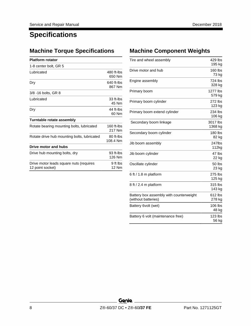
Machine Torque Specifications Platform rotator 1-8 center bolt, GR 5 Lubricated 480 ft-lbs
650 Nm Dry 640 ft-lbs
867 Nm 3/8 -16 bolts, GR 8 Lubricated 33 ft-lbs
45 Nm Dry 44 ft-lbs
60 Nm
Turntable rotate assembly Rotate bearing mounting bolts, lubricated 160 ft-lbs
217 Nm Rotate drive hub mounting bolts, lubricated 80 ft-lbs
108.4 Nm Drive motor and hubs Drive hub mounting bolts, dry 93 ft-lbs
126 Nm Drive motor leads square nuts (requires 12 point socket)
9 ft lbs 12 Nm
Machine Component Weights Tire and wheel assembly 429 lbs
195 kg
Drive motor and hub 160 lbs 73 kg
Engine assembly 724 lbs 328 kg
Primary boom 1277 lbs 579 kg
Primary boom cylinder 272 lbs 123 kg
Primary boom extend cylinder 234 lbs 106 kg
Secondary boom linkage 3017 lbs 1368 kg
Secondary boom cylinder 180 lbs 82 kg
Jib boom assembly 247lbs 112kg
Jib boom cylinder 47 lbs 22 kg
Oscillate cylinder 50 lbs 23 kg
6 ft / 1.8 m platform 275 lbs 125 kg
8 ft / 2.4 m platform 315 lbs 143 kg
Battery box assembly with counterweight (without batteries)
612 lbs 278 kg
Battery 6volt (wet) 106 lbs 48 kg
Battery 6 volt (maintenance free) 123 lbs 56 kg
December 2018 Service and Repair Manual
Specifications
Part No. 1271125GT Z®-60/37 DC • Z®-60/37 FE 9
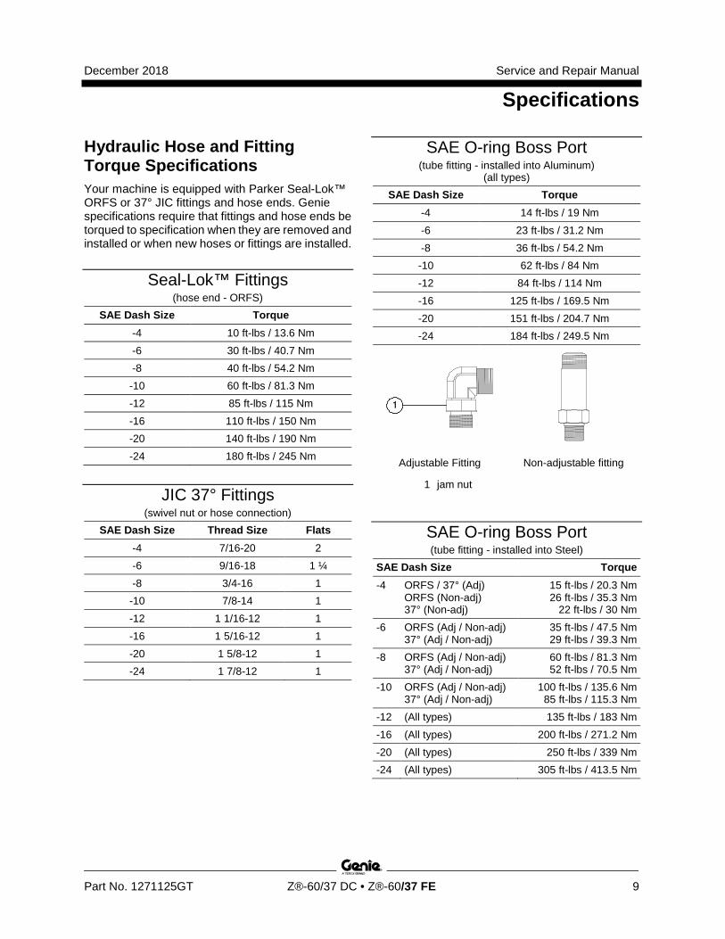
Hydraulic Hose and Fitting Torque Specifications Your machine is equipped with Parker Seal-Lok™ ORFS or 37° JIC fittings and hose ends. Genie specifications require that fittings and hose ends be torqued to specification when they are removed and installed or when new hoses or fittings are installed.
Seal-Lok™ Fittings (hose end - ORFS)
SAE Dash Size Torque -4 10 ft-lbs / 13.6 Nm -6 30 ft-lbs / 40.7 Nm -8 40 ft-lbs / 54.2 Nm -10 60 ft-lbs / 81.3 Nm -12 85 ft-lbs / 115 Nm -16 110 ft-lbs / 150 Nm -20 140 ft-lbs / 190 Nm -24 180 ft-lbs / 245 Nm
JIC 37° Fittings (swivel nut or hose connection)
SAE Dash Size Thread Size Flats -4 7/16-20 2 -6 9/16-18 1 ¼ -8 3/4-16 1
-10 7/8-14 1 -12 1 1/16-12 1 -16 1 5/16-12 1 -20 1 5/8-12 1 -24 1 7/8-12 1
SAE O-ring Boss Port (tube fitting - installed into Aluminum)
(all types) SAE Dash Size Torque
-4 14 ft-lbs / 19 Nm -6 23 ft-lbs / 31.2 Nm -8 36 ft-lbs / 54.2 Nm -10 62 ft-lbs / 84 Nm -12 84 ft-lbs / 114 Nm -16 125 ft-lbs / 169.5 Nm -20 151 ft-lbs / 204.7 Nm -24 184 ft-lbs / 249.5 Nm
Adjustable Fitting Non-adjustable fitting
1 jam nut
SAE O-ring Boss Port (tube fitting - installed into Steel)
SAE Dash Size Torque -4 ORFS / 37° (Adj)
ORFS (Non-adj) 37° (Non-adj)
15 ft-lbs / 20.3 Nm 26 ft-lbs / 35.3 Nm
22 ft-lbs / 30 Nm -6 ORFS (Adj / Non-adj)
37° (Adj / Non-adj) 35 ft-lbs / 47.5 Nm 29 ft-lbs / 39.3 Nm
-8 ORFS (Adj / Non-adj) 37° (Adj / Non-adj)
60 ft-lbs / 81.3 Nm 52 ft-lbs / 70.5 Nm
-10 ORFS (Adj / Non-adj) 37° (Adj / Non-adj)
100 ft-lbs / 135.6 Nm 85 ft-lbs / 115.3 Nm
-12 (All types) 135 ft-lbs / 183 Nm -16 (All types) 200 ft-lbs / 271.2 Nm -20 (All types) 250 ft-lbs / 339 Nm -24 (All types) 305 ft-lbs / 413.5 Nm
Service and Repair Manual December 2018
Specifications
10 Z®-60/37 DC • Z®-60/37 FE Part No. 1271125GT
Torque Procedure
Seal-Lok™ fittings 1 Replace the O-ring. The O-ring must be
replaced anytime the seal has been broken. The O-ring cannot be re-used if the fitting or hose end has been tightened beyond finger tight.
Note: The O-ring in Parker Seal Lok™ fittings and hose end are custom-size O-rings. They are not standard size O-rings. They are available in the O-ring field service kit (Genie part number 49612).
2 Lubricate the O-ring before installation.
3 Be sure the O-ring face seal is seated and retained properly.
4 Position the tube and nut squarely on the face seal end of the fitting, and tighten the nut finger tight.
5 Tighten the nut or fitting to the appropriate torque. Refer to the appropriate torque chart in this section.
6 Operate all machine functions and inspect the hose, fittings and related components to confirm there are no leaks.
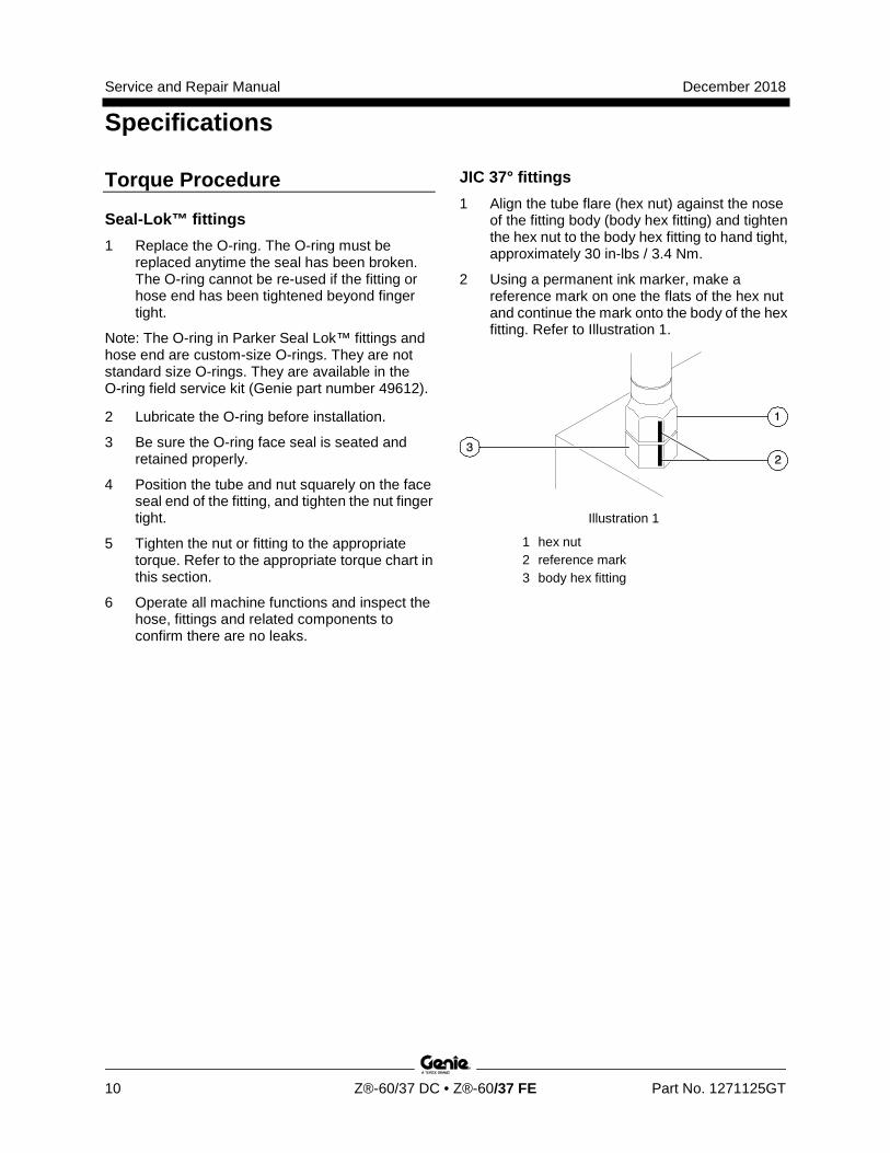
JIC 37° fittings 1 Align the tube flare (hex nut) against the nose
of the fitting body (body hex fitting) and tighten the hex nut to the body hex fitting to hand tight, approximately 30 in-lbs / 3.4 Nm.
2 Using a permanent ink marker, make a reference mark on one the flats of the hex nut and continue the mark onto the body of the hex fitting. Refer to Illustration 1.
Illustration 1
1 hex nut 2 reference mark 3 body hex fitting
December 2018 Service and Repair Manual
Specifications
Part No. 1271125GT Z®-60/37 DC • Z®-60/37 FE 11
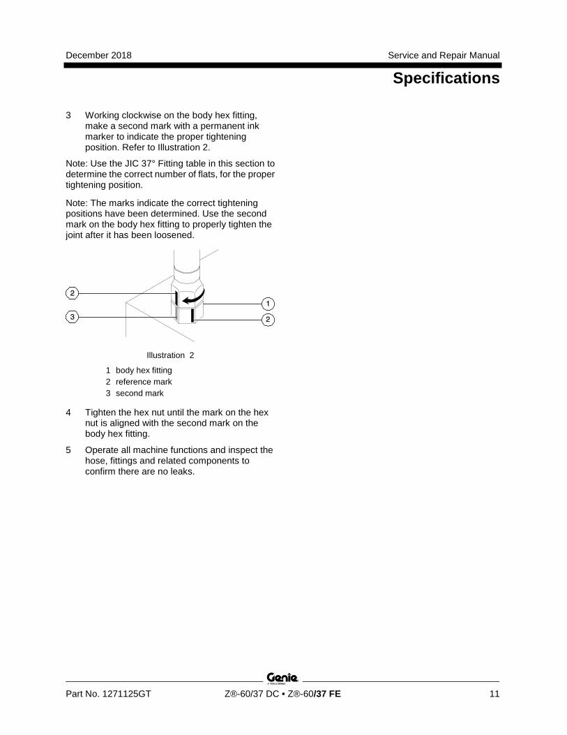
3 Working clockwise on the body hex fitting, make a second mark with a permanent ink marker to indicate the proper tightening position. Refer to Illustration 2.
Note: Use the JIC 37° Fitting table in this section to determine the correct number of flats, for the proper tightening position.
Note: The marks indicate the correct tightening positions have been determined. Use the second mark on the body hex fitting to properly tighten the joint after it has been loosened.
Illustration 2
1 body hex fitting 2 reference mark 3 second mark
4 Tighten the hex nut until the mark on the hex nut is aligned with the second mark on the body hex fitting.
5 Operate all machine functions and inspect the hose, fittings and related components to confirm there are no leaks.
Service and Repair Manual December 2018
Repair Procedures
12 Z®-60/37 DC • Z®-60/37 FE Part No. 1271125GT
Section 3 Repair Pr ocedures
Observe and Obey: R Repair procedures shall be completed by a
person trained and qualified on the repair of this machine.
R Immediately tag and remove from service a damaged or malfunctioning machine.
R Repair any machine damage or malfunction before operating the machine.
Before Repairs Start: R Read, understand and obey the safety rules
and operating instructions in the appropriate operator's manual on your machine.
R Be sure that all necessary tools and parts are available and ready for use.
R Use only Genie approved replacement parts.
R Read each procedure completely and adhere to the instructions. Attempting shortcuts may produce hazardous conditions.
Machine Configuration: R Unless otherwise specified, perform each
repair procedure with the machine in the following configuration:
· Machine parked on a firm, level surface
· Key switch in the off position with the key removed
· The red Emergency Stop button in the off position at both the ground and platform controls
· Wheels chocked
· All external AC power supply disconnected from the machine
· Boom in the stowed position
· Turntable secured with the turntable rotation lock
December 2018 Service and Repair Manual
Repair Procedures
Part No. 1271125GT Z®-60/37 DC • Z®-60/37 FE 13
About This Section Most of the procedures in this section should only be performed by trained service professional in a suitably equipped workshop. Select the appropriate repair procedure after troubleshooting the problem.
Perform disassembly procedures to the point where repairs can be completed. Then to re-assemble, perform the disassembly steps in reverse order.
Symbols Legend
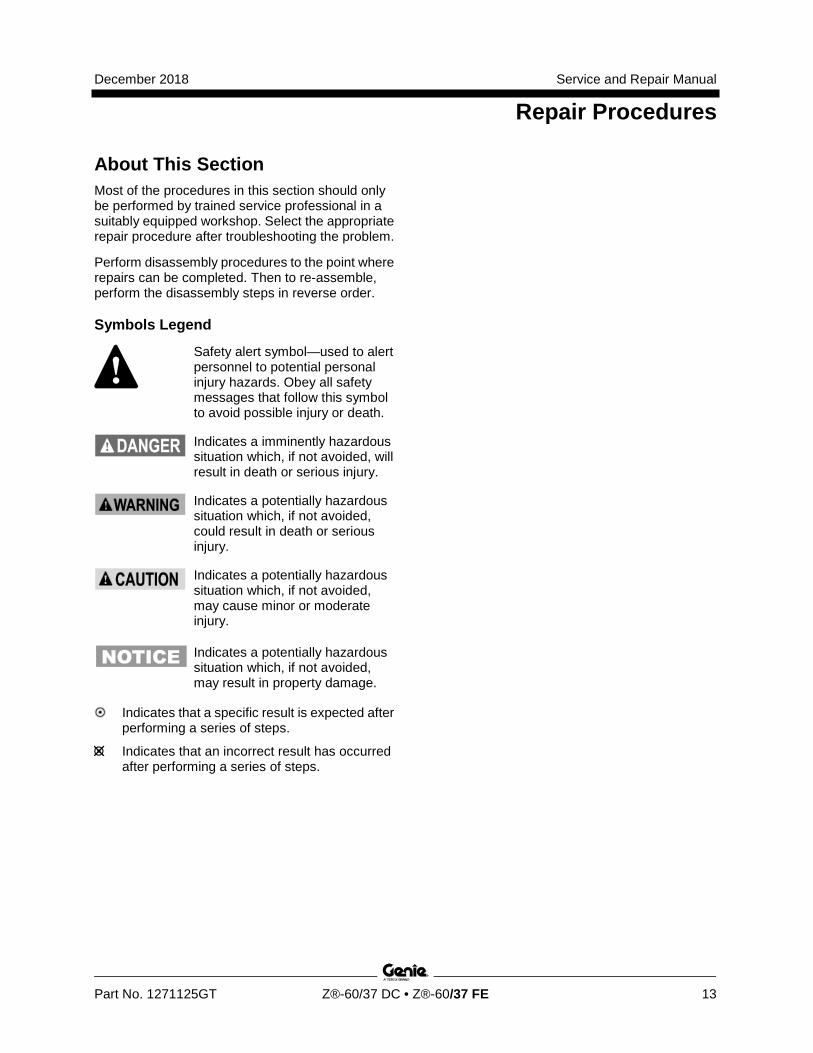
Safety alert symbol—used to alert personnel to potential personal injury hazards. Obey all safety messages that follow this symbol to avoid possible injury or death.
Indicates a imminently hazardous situation which, if not avoided, will result in death or serious injury.
Indicates a potentially hazardous situation which, if not avoided, could result in death or serious injury.
Indicates a potentially hazardous situation which, if not avoided, may cause minor or moderate injury.
Indicates a potentially hazardous situation which, if not avoided, may result in property damage.
Indicates that a specific result is expected after performing a series of steps.
Indicates that an incorrect result has occurred after performing a series of steps.
Service and Repair Manual December 2018
Repair Procedures
14 Z®-60/37 DC • Z®-60/37 FE Part No. 1271125GT
Calibration Process Steps It is required to perform the calibration process if system defaults have been reset or if new software has been installed. Any deviation in the order of these steps could result in improper machine function and fault codes to display.
1 Set system defaults: Turn the machine on at the ground controls and immediately move and hold both the function enable and auxiliary enable switches for 5 seconds
Result: an alarm will sound indicating the system has been restored to defaults.
2 Calibrate the pressure relief valve: Refer to Repair Procedures, How to Adjust the Proportional Relief Valve and Hydraulic Pressure Sensor.
Note: Perform this procedure prior to calibrating other hydraulic functions.
3 Calibrate the universal tilt sensor: Refer to Repair Procedures, How to Calibrate Universal Tilt Sensor.
4 Calibrate the primary and secondary angle sensor stowed positions: Refer to Repair Procedures, How to Calibrate Booms Angle Sensors.
Note: The one point calibration is optional. It allows 2 MPH / 3.2 Km/h travel if machine needs to be immediately moved.
5 Calibrate the steer angle sensor: Refer to Repair Procedures, How to Calibrate the Steer Angle Sensor.
6 Complete calibrating the Primary and Secondary angle sensors stowed and elevated positions: Refer to Repair Procedures, How to Calibrate Booms Angle Sensors.
7 Verify pump efficiency calibration: Refer to Repair Procedures, How to Calibrate Function Pump.
8 Set hydraulic valve thresholds for turntable rotate, primary up/down, secondary up/down, primary extend/retract, jib up/down, and platform rotate: Refer to Repair Procedures, How to Adjust the Joystick Threshold Setting.
9 Set low flow hydraulic valves for jib up/down and platform rotate: Refer to Repair Procedures, How to Adjust the Maximum Speed Setting (Hydraulic Functions).
10 Set high flow hydraulic valves for primary up/down, secondary up/down, primary extend/retract and turntable rotate: Refer to Repair Procedures, How to Adjust the Maximum Speed Setting (Hydraulic Functions).
11 Check oscillate function (if equipped).
12 Clear the fault history: Refer to Repair Procedure, How to Clear Fault History.
December 2018 Service and Repair Manual
Platform Controls
Part No. 1271125GT Z®-60/37 DC • Z®-60/37 FE 15
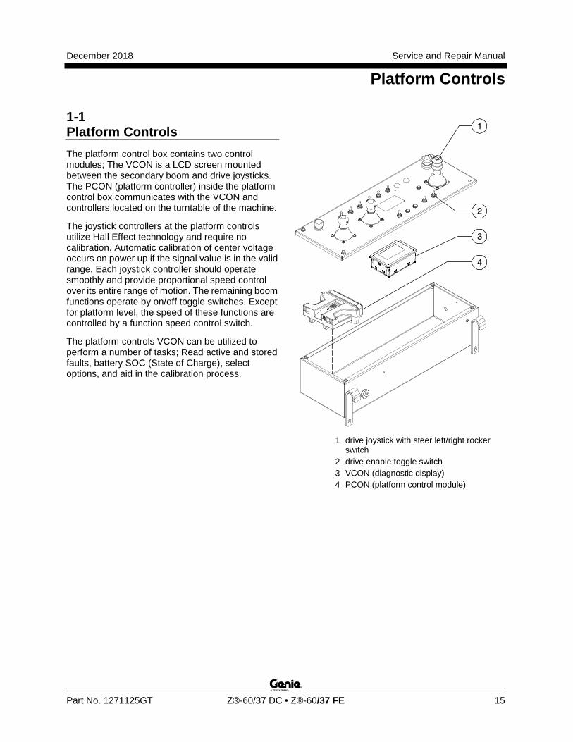
1-1 Platform Controls The platform control box contains two control modules; The VCON is a LCD screen mounted between the secondary boom and drive joysticks. The PCON (platform controller) inside the platform control box communicates with the VCON and controllers located on the turntable of the machine.
The joystick controllers at the platform controls utilize Hall Effect technology and require no calibration. Automatic calibration of center voltage occurs on power up if the signal value is in the valid range. Each joystick controller should operate smoothly and provide proportional speed control over its entire range of motion. The remaining boom functions operate by on/off toggle switches. Except for platform level, the speed of these functions are controlled by a function speed control switch.
The platform controls VCON can be utilized to perform a number of tasks; Read active and stored faults, battery SOC (State of Charge), select options, and aid in the calibration process.
1 drive joystick with steer left/right rocker switch
2 drive enable toggle switch 3 VCON (diagnostic display) 4 PCON (platform control module)
Service and Repair Manual December 2018
Platform Controls
16 Z®-60/37 DC • Z®-60/37 FE Part No. 1271125GT
How to Adj ust the Joystick Thr eshol d Setting
How to Adjust the Threshold Setting The threshold setting is the minimum output current at which a function proportional valve can open and allow the function to operate. There are two types threshold currents to adjust:
Joystick controlled functions - Primary Up/Down, Secondary Up/Down and Turntable Rotate. Switch controlled functions - Primary Extend/Retract, Platform Rotate, Jib Up/Down and Jib Rotate.
The boom functions threshold current should be operating at near zero speed smoothly with no vibrations.
Note: Perform this procedure with the boom in the stowed position. Refer to Navigation Menus, Settings Menu.
1 Turn the key switch to platform control. Do not start the engine (if equipped).
2 Pull out the red Emergency Stop button to the 'ON' position at both the ground and platform controls.
3 Do not press down the foot switch.
4 Move and hold the drive enable toggle switch in the right direction while holding steer in the right direction.
5 When the display leaves SYSTEM READY mode, release the drive enable toggle switch and steer joystick.
Result: The display will show FAULTS.
6 Momentarily activate steer in the right direction until SETTINGS is shown on the display.
7 Momentarily activate the drive enable toggle switch in the right direction until VALVE AND SENSOR SETTINGS is shown on the display.
8 Momentarily activate the drive enable toggle switch in the right direction until CALIBRATE TILT SENSOR is shown on the display.
9 Momentarily activate steer in the right direction until VALVE THRESHOLD CURRENT is shown on the display.
Joystick Controlled Functions:
10 Press down on the foot switch and slowly deflect the joystick to be adjusted until the valve is operating at the desired threshold current.
Result: The display will indicate the threshold current parameter in milliamps while operating the function.
11 While operating the function and the function is barely moving, momentarily activate the drive enable toggle switch in the right direction to save the desired value.
Result: The alarm will sound indicating the setting has been saved. Release the foot switch. Continue to the next threshold current adjustment.
Switch Controlled Functions:
12 Perform steps 1 through 9 to enter the sub menu THRESHOLD CURRENT on the display.
13 Momentarily activate the speed select toggle switch in either direction until the bar graph is at about 50% on the display.
December 2018 Service and Repair Manual
Platform Controls
Part No. 1271125GT Z®-60/37 DC • Z®-60/37 FE 17
14 Press down on the foot switch and select the toggle switch controlled boom function to be adjusted.
Result: The display will indicate the parameter in milliamps while operating the function.
15 Momentarily activate the speed select switch in either direction while operating the function (foot switch depressed) to achieved the desired threshold value. Do not release the foot switch.
16 Momentarily activate the drive enable toggle switch in the right direction to save the value.
Result: The alarm will sound indicating the setting has been saved. Release the foot switch. Continue to the next threshold current adjustment.
To exit programming mode:
17 Move and hold the drive enable toggle in the left position until the display returns to SYSTEM READY mode.
How to Adj ust the Joystick Max- out Setting
How to Adjust the Maximum Speed Setting (Hydraulic Functions) There are three types of speed settings to adjust: High Flow Functions: Primary Up/Down Primary Extend/Retract, Secondary Up/Down and Turntable rotate. Low flow Functions: Jib Up/Down, Jib rotate, and Platform rotate. Other Functions: Steering is set by a fixed flow regulating valve (non adjustable), Platform level (adjusted by a needle valve located on the function manifold) and Hydraulic Valve Ramps. Refer to How to Adjust Ramp Rate Setting.
Note: Refer to Specifications, Performance Specifications, for each boom function speed. Check function pump calibration before adjusting the maximum speed setting. Refer to Repair Procedures, How to Check Function Pump Calibration.
1 Turn the key switch to platform control.
2 Pull out the red Emergency Stop button to the 'ON' position at both the ground and platform controls.
3 Do not press down the foot switch.
4 Move and hold the drive enable toggle switch in the right direction while holding steer in the right direction.
5 When the display leaves SYSTEM READY mode, release the drive enable toggle switch and the steer joystick.
Result: The display will show FAULTS.
6 Momentarily activate steer in the right direction until SETTINGS is shown on the display.
7 Momentarily activate the drive enable toggle switch in the right direction until VALVE AND SENSOR SETTINGS is shown on the display.
Service and Repair Manual December 2018
Platform Controls
18 Z®-60/37 DC • Z®-60/37 FE Part No. 1271125GT
8 Momentarily activate the drive enable toggle switch in the right direction until CALIBRATE TILT SENSOR is shown on the display.
9 Momentarily activate steer in the right direction until VALVE MAXIMUM CURRENT is shown on the display.
10 Momentarily activate the drive enable switch to enter the sub menu VALVE MAXIMUM CURRENT.
High Flow Functions:
The function speeds are fixed by the flow rate supplied by the hydraulic pump. Excess flow is rarely produced resulting in little or no oil going over relief.
11 Momentarily activate and release the high flow boom function in one direction.
Result: The display shows the name, direction and current value in milliamps for the function being moved. Example: “PRI_UP_MAX 590.”
12 Momentarily activate steer right five times to increase the mA value.
13 Activate the boom function again by pressing the foot switch and moving the function switch (or joystick to full speed) in the same direction. Momentarily active steer left once every three seconds to decrease the maximum mA value where pressure rises to about 3000 PSI / 207 bar and an audible alarm sounds.
Note: The turntable function will only increase 300 PSI and no audible alarm. When the 300 PSI occurs, proceed to the next step.
14 Release the foot switch and momentarily activate steer in the right direction one time to increase the value by 10 milliamps. Repeat releasing the foot switch and momentarily activating steer right until the function moves with no valve throttling and no audible alarm for the primary up/down, secondary up/down and primary boom extend and retract.
15 Momentarily activate steer in the right direction three times to increase the value by 30 milliamps for the turntable function setting.
16 Momentarily activate the drive enable switch to the right to save the value.
Result: The alarm will sound indicating the setting has been saved. Continue to the next desired high flow function adjustment.
To exit programming mode:
17 Move and hold the drive enable toggle in the left position until the display returns to SYSTEM READY mode.
December 2018 Service and Repair Manual
Platform Controls
Part No. 1271125GT Z®-60/37 DC • Z®-60/37 FE 19
Low Flow Functions:
Hydraulic flow from the pump is fixed, and the function speed is controlled by the hydraulic directional control valve. Hydraulic flow will always exceed the flow allowed by the controlling valve and the excess flow will always be sent over the relief valve and back to tank. Function speed is set by changing control current (mA) and is confirmed by timing the function travel time with a stop watch. Refer to Specifications, Performance Specifications for each boom function speed.
18 Perform steps 1 through 10 to enter the sub menu VALVE MAXIMUM CURRENT on the display.
19 Momentarily active a low flow boom function in one direction.
Result: The display shows the name of the function, direction and current value in milliamps for the function being moved. Example: “JIB_UP_MAX 590.”
20 Activate the boom function again by pressing the foot switch and moving the function switch in the same direction. Using a stop watch, record the full motion function and compare this time to the performance specification.
21 While performing the function, activate steer in either direction to reach the desired speed.
Note: Activating steer right decreases the time it takes to perform the low flow boom function. Activating steer left increases the time it takes to perform the low flow boom function.
22 Momentarily activate the drive enable switch to the right to save the value.
Result: The alarm will sound indicating the setting has been saved. Continue to the next low flow function adjustment.
To exit programming mode:
23 Move and hold the drive enable toggle in the left position until the display returns to SYSTEM READY mode.
Service and Repair Manual December 2018
Platform Controls
20 Z®-60/37 DC • Z®-60/37 FE Part No. 1271125GT
How to Adj ust the Joystick Ramp R ate Setting
How to Adjust the Ramp Rate Setting The ramp rate setting is an adjustment that controls the way boom function starts and stops. There are two types of ramp rates to adjust on separate menus:
Ramp Up Time: The amount of time it takes to accelerate to speed. Ramp Down Time: The amount of time it takes to decelerate to a stop.
Note: Perform this procedure with the boom in the stowed position. Refer to Navigation Menus, Settings Menu.
1 Turn the key switch to platform control. Do not start the engine (if equipped).
2 Pull out the red Emergency Stop button to the on position at both the ground and platform controls.
3 Do not press down the foot switch.
4 Move and hold the drive enable toggle switch in the right direction while holding steer in the right direction.
5 When the display leaves SYSTEM READY mode, release the drive enable toggle switch and the steer joystick.
Result: The display will show FAULTS.
6 Momentarily activate steer in the right direction until SETTINGS is shown on the display.
7 Momentarily activate the drive enable toggle switch in the right direction until VALVE AND SENSOR SETTINGS is shown on the display.
8 Momentarily activate the drive enable toggle switch in the right direction until CALIBRATE TILT SENSOR is shown on the display.
9 Momentarily activate steer in the right direction to choose either RAMP UP TIME or RAMP DOWN TIME sub menus.
10 Momentarily activate the drive enable toggle switch in the right direction to enter the desired ramp time calibration sub menu.
11 Momentarily activate the boom function to be adjusted.
Result: The display shows the name of the function, direction, and time value in milliseconds. Example "PRI_UP_VALVE 2500" (2500 milliseconds / 2.5 seconds of ramp time).
Note: At this step, the function can be tested and ramp times can be measured. Release the foot switch prior to making a parameter adjustment.
12 Momentarily active steer to change the ramp up or ramp down value. Each activation will change the value by 50 milliseconds. Refer to the Ramp Rate chart for factory settings.
December 2018 Service and Repair Manual
Platform Controls
Part No. 1271125GT Z®-60/37 DC • Z®-60/37 FE 21
13 Momentarily activate drive enable switch right to save the value.
Result: The alarm will sound indicating the setting has been saved. Continue to the next desired Ramp time adjustment.
Ramp Rate (factory settings)
Primary boom up/down ramp accelerate (up) ramp decelerate (down)
2 seconds
0.6 second Secondary boom up/down ramp accelerate (up) ramp decelerate (down)
1.5 second 0.5 second
Turntable rotate ramp accelerate (up) ramp decelerate (down)
1.85 seconds 1.25 seconds
Extend/Retract ramp accelerate (up) ramp decelerate (down)
2 seconds
0.4 second Jib up/down ramp accelerate (up) ramp decelerate (down)
1 second
0.4 second Platform rotate ramp accelerate (up) ramp decelerate (down)
0.3 second
0.75 second Propel ramp accelerate (up) ramp decelerate (down)
5 seconds 3 seconds
1-2 How to Calibrate Booms Angle Sensors Boom angle sensors are installed on the primary and secondary boom sections. They are used to detect whether the boom sections are stowed or not stowed. A two point calibration procedure captures the signal with the cylinder fully extended and fully retracted to an angle measurement that is scaled to degrees within the program. If either angle sensor is in the uncalibrated state, drive speed is limited to out-of-stowed speed.
Note: Start this procedure with the boom in a stowed position. Position the machine in a suitable location with sufficient vertical space. Refer to Navigation Menus, Settings Menu.
1 Pull out the red Emergency Stop button to the on position at both the ground and platform controls.
2 Move and hold the drive enable toggle switch in the right direction while holding steer in the right direction.
3 When the display leaves SYSTEM READY mode, release the drive enable toggle switch and the steer joystick.
Result: The display will show FAULTS.
4 Momentarily activate steer in the right direction until SETTINGS is shown on the display.
5 Momentarily activate the drive enable toggle switch in the right direction until you see the VALVE AND SENSOR SETTINGS screen.
6 Momentarily activate the drive enable toggle switch in the right direction until you see the CALIBRATE TILT SENSOR screen.
Service and Repair Manual December 2018
Platform Components
22 Z®-60/37 DC • Z®-60/37 FE Part No. 1271125GT
7 Momentarily activate steer in the right direction until BOOM ANGLE CALIBRATE is shown on the display.
8 Momentarily activate the drive enable toggle switch in the right direction to enter the BOOM ANGLE CALIBRATE screen.
9 Momentarily activate the drive enable toggle switch in the right direction to enter the sub-menu.
Result: The screen will display PRI SNSR MVXXXX, SEC SNSR MVXXXX. A flashing value indicates the mV (millivolt) value is within expected range.
10 Momentarily activate the drive enable toggle switch in the right direction to store the millivolt value.
Result: An alarm will sound for one second and the screen will display CALIBRATED.
11 Calibrate the boom elevated positions, fully raise the primary and secondary booms. Repeat steps 9 and 10 to store the millivolt value.
Result: An alarm will sound for two seconds and the screen will display CALIBRATED indicating both the primary and secondary angle sensors have been calibrated successfully.
To exit programming mode:
12 Move and hold the drive enable toggle in the left position until the display returns to SYSTEM READY mode.
1-3 How to Clear Fault History There are 1 thru 16 fault codes shown in the fault history menu 1 being the most recent displayed. It may be necessary to clear the fault history in order to acquire the most recent fault codes. It is also good practice to clear fault history after performing any calibration procedure.
Note: Perform this procedure with the boom in the stowed position. Refer to Navigation Menus, Faults Menu.
1 Turn the key switch to platform control. Do not start the engine (if equipped)
2 Pull out the red Emergency Stop button to the on position at both the ground and platform controls.
3 Do not press down the foot switch.
4 Move and hold the drive enable toggle switch in the right direction while holding steer in the right direction.
5 When the display leaves SYSTEM READY mode, release the drive enable toggle switch and steer joystick.
Result: The display will show FAULTS.
6 Momentarily activate the drive enable toggle switch in the right direction until ACTIVE FAULTS is shown on the display.
7 Momentarily activate steer in the right direction until FAULT HISTORY is shown on the display.
8 Momentarily activate the drive enable toggle switch in the right direction to activate the clear fault history function
Result: The display will read ENABLE at the bottom.
9 Momentarily activate steer in the right direction to change NO to YES on the display.
10 Momentarily activate the drive enable toggle switch to except the change.
Result: The alarm will sound indicating the fault history has been cleared.
December 2018 Service and Repair Manual
Platform Components
Part No. 1271125GT Z®-60/37 DC • Z®-60/37 FE 23
2-1 Platform Leveling Cylinder The slave cylinder and the rotator pivot are the two primary supports for the platform. The slave cylinder keeps the platform level through the entire range of boom motion. It operates in a closed-circuit hydraulic loop with the master cylinder. The slave cylinder is equipped with counterbalance valves to prevent movement in the event of a hydraulic line failure.
How to Remove the Platform Leveling Cylinder Note: Before cylinder removal is considered, bleed the slave cylinder to be sure there is no air in the closed loop.
Note: When removing a hose assembly or fitting, the O-ring (if equipped) on the fitting and/or hose end must be replaced. All connections must be torqued to specification during installation. Refer to Specifications, Hydraulic Hose and Fitting Torque Specifications.
1 Extend the primary boom until the slave cylinder barrel-end pivot pin is accessible.
2 Raise the jib boom slightly and place blocks under the platform for support.
3 Lower the jib boom until the platform is resting on the blocks just enough to support the platform.
Note: Do not rest the entire weight of the jib boom on the blocks.
4 Tag, disconnect and cap the hydraulic hoses from the slave cylinder. Plug the union hoses from the master cylinder together using a connector.
Bodily injury hazard. Spraying hydraulic oil can penetrate and burn skin. Loosen hydraulic connections very slowly to allow the oil pressure to dissipate gradually. Do not allow oil to squirt or spray.
5 Remove the pin retaining fastener from the slave cylinder rod-end pivot pin. Do not remove the pin.
6 Remove the external snap rings from the slave cylinder barrel-end pivot pin. Do not remove the pin.
7 Place a block under the slave cylinder for support. Protect the cylinder rod from damage.
8 Use a soft metal drift to drive the rod-end pivot pin out.
Crushing hazard. The platform could fall when the slave cylinder rod-end pivot pin is removed if not properly supported.
Component damage hazard. The slave cylinder rod may become damaged if it is allowed to fall if not properly supported by the lifting device.
9 Use a soft metal drift and drive the barrel-end pin out.
10 Carefully pull the cylinder out of the primary boom.
How to Bleed the Platform Leveling Cylinder 1 Simultaneously activate the primary boom up
function and the platform level up function until the boom is fully raised.
2 Simultaneously activate the primary boom down function and the platform level down function until the boom is fully lowered.
Service and Repair Manual December 2018
Platform Components
24 Z®-60/37 DC • Z®-60/37 FE Part No. 1271125GT
2-2 Platform Rotator
How to Remove the Platform Rotator
Component damage hazard. Mark the platform mounting weldment and the rotator flange before removing the platform mounting weldment. The platform mounting weldment must be replaced in the exact same position on the rotator flange as it was before removal. If a new rotator is installed or the rotator is disassembled, proper alignment can be achieved by rotating the rotator all the way to the left and then installing the platform mounting weldment all the way in the left position.
Note: When removing a hose assembly or fitting, the O-ring (if equipped) on the fitting and/or hose end must be replaced. All connections must be torqued to specification during installation. Refer to Specifications, Hydraulic Hose and Fitting Torque Specifications.
1 Remove the platform and platform support.
2 Tag, disconnect and plug the hydraulic hoses from the platform rotator manifold. Cap the fittings on the rotator.
Bodily injury hazard. Spraying hydraulic oil can penetrate and burn skin. Loosen hydraulic connections very slowly to allow the oil pressure to dissipate gradually. Do not allow oil to squirt or spray.
3 Support the platform rotator with an appropriate lifting device. Do not apply any lifting pressure.
Crushing hazard. The platform rotator may become unbalanced and fall if not properly supported.
How to Bleed the Platform Rotator Note: This procedure will require two people. Do not start the engine. Use auxiliary power for this procedure.
1 Move the function enable toggle switch to either side and activate the platform rotate toggle switch to the right then the left through two platform rotation cycles, then hold the switch to the right position until the platform is fully rotated to the right.
2 Place a suitable container underneath the platform rotator.
3 Open the top bleed screw on the rotator, but do not remove it.
Bodily injury hazard. Spraying hydraulic oil can penetrate and burn skin. Loosen hydraulic connections very slowly to allow the oil pressure to dissipate gradually. Do not allow oil to squirt or spray.
4 Move the function enable toggle switch to either side and hold the platform rotate toggle switch to the left position until the platform is fully rotated to the left. Continue holding the toggle switch until air stops coming out of the bleed screw. Close the bleed screw.
Crushing hazard. Keep clear of the platform during rotation.
December 2018 Service and Repair Manual
Platform Components
Part No. 1271125GT Z®-60/37 DC • Z®-60/37 FE 25
5 Open the bottom bleed screw on the rotator, but do not remove it.
Bodily injury hazard. Spraying hydraulic oil can penetrate and burn skin. Loosen hydraulic connections very slowly to allow the oil pressure to dissipate gradually. Do not allow oil to squirt or spray.
6 Move the function enable toggle switch to either side and hold the platform rotate toggle switch to the right position until the platform is fully rotated to the right. Continue holding the toggle switch until air stops coming out of the bleed screw. Close the bleed screw.
Crushing hazard. Keep clear of the platform during rotation.
7 Clean up any hydraulic oil that may have spilled.
8 Rotate the platform fully in both directions and inspect the bleed screws for leaks.
2-3 Platform Overload System (if equipped)
How to Calibrate the Platform Overload System Calibrating the platform overload system regularly is essential to safe machine operation. Continued use of an improperly operating platform overload system, could result in the system not sensing an overloaded platform condition. Machine stability could be compromised resulting in the machine tipping over.
Note: Perform this procedure with the machine on a firm, level surface.
1 Turn the key switch to platform control. Level the platform.
2 Determine the maximum platform capacity. Refer to the machine serial plate.
3 Remove all weight, tools and accessories from the platform.
Note: Failure to remove all weight, tools and accessories from the platform will result in an incorrect calibration.
4 Using a suitable lifting device, place a test weight equal to the maximum platform capacity at the center of the platform floor. Refer to the machine serial plate.

Service and Repair Manual December 2018
Platform Components
26 Z®-60/37 DC • Z®-60/37 FE Part No. 1271125GT
5 Move the platform up and down by hand, so it bounces approximately 2.5 to 5 cm / 1 to 2 inches. Allow the platform to settle.
Result: The overload indicator lights are off and the alarm does not sound. Proceed to step 6.
Result: The system will flash the red “Platform Overloaded” LEDs and turn on an audible alarm at both the platform and ground control stations. Slowly tighten the load spring adjustment nut in a clockwise direction in 10° increments until the overload indicator light turns off, and the alarm does not sound. Repeat step 5.
Note: The platform will need to be moved up and down and allowed to settle between each adjustment.
Note: There may be a 2 second delay before the platform overload indicator light and alarm responds.
6 Turn the key switch to ground controls, pull out the red Emergency Stop Button.
7 Add an additional weight to the platform that is equal to, but does not exceed 15% of the maximum rated load.
Result: The overload indicator light is flashing at both the ground and platform controls, the alarm is sounding. Proceed to step 8.
Result: The overload indicator lights are off at the platform and ground controls, the alarm does not sound. Slowly loosen the load spring adjustment nut in a counterclockwise direction in 10° increments until the overload indicator light flashes at both the platform and ground controls, the alarm sounds and the engine shuts down. Remove the additional weight. Repeat the procedure starting with step 5.
Note: There may be a 2 second delay before the platform overload indicator light and alarm responds.
8 Using auxiliary power, test all machine functions from the ground controls.
Result: All ground control functions should operate.
9 Using a suitable lifting device, remove the additional weight from the platform.
Result: The platform overload indicator light should be off at both the ground and platform controls and the alarm should not sound.
Note: There may be a 2 second delay before the overload indicator lights and alarm turn off.
10 Test all machine functions using the function enable switch at the ground controls.
Result: All ground control functions should operate.
December 2018 Service and Repair Manual
Platform Components
Part No. 1271125GT Z®-60/37 DC • Z®-60/37 FE 27
2-4 How to Reset Overload Recovery Faults The message OVERLOAD RECOVERY will be displayed when a platform overload recovery occurs under auxiliary power. The message will persist until the reset overload recovery procedure is performed. Refer to Navigation Menus, Faults Menu.
1 Turn the key switch to platform control.
2 Pull out the red Emergency Stop button to the on position at both the ground and platform controls.
3 Do not press down the foot switch.
4 Move and hold the drive enable toggle switch and steer in the right direction.
5 When the display leaves SYSTEM READY mode, release the drive enable toggle switch and the steer joystick.
Result: The display will show FAULTS.
6 Momentarily activate the drive enable toggle switch in the right direction until ACTIVE FAULTS is shown on the display.
7 Activate steer in the right direction until RESET OVERLOAD RECOVERY is shown on the display.
8 Momentarily activate the drive enable toggle switch in the right direction to lock the menu OVERLOAD RECOVERY RESET.
9 Enter the reset code by momentarily activating steer right three times then steer left one time.
Result: A one second pulse alarm will sound indicating the reset procedure has been saved.
Service and Repair Manual December 2018
Jib Boom Components
28 Z®-60/37 DC • Z®-60/37 FE Part No. 1271125GT
3-1 Jib Boom
How to Remove the Jib Boom Note: Perform this procedure with the boom in the stowed position.
Note: When removing a hose assembly or fitting, the O-ring (if equipped) on the fitting and/or hose end must be replaced. All connections must be torqued to specification during installation. Refer to Specifications, Hydraulic Hose and Fitting Torque Specifications.
1 Remove the platform and platform support.
2 Disconnect the electrical connector from the jib boom/platform rotate select valve manifold mounted to the platform support.
3 Tag, disconnect and plug all of the hydraulic hoses from the jib boom/platform rotate select valve manifold. Cap the fittings on the manifold.
Bodily injury hazard. Spraying hydraulic oil can penetrate and burn skin. Loosen hydraulic connections very slowly to allow the oil pressure to dissipate gradually. Do not allow oil to squirt or spray.
4 Remove the platform rotator. Refer to Repair Procedure, How to Remove the Platform rotator.
5 Remove the pin retaining fastener from the jib boom lift cylinder rod-end pivot pin. Do not remove the pin.
6 Slide both of the jib boom leveling arms off of the jib boom cylinder rod-end pivot pin.
7 Remove the hose and cable cover from the side of the jib boom. Remove the hose and cable separators.
8 Attach a lifting strap from an overhead crane to the jib boom.
9 Support the barrel end of the jib boom lift cylinder with a suitable lifting device.
10 Tag, disconnect and plug the jib boom lift cylinder hydraulic hoses. Cap the fittings on the cylinder.
Bodily injury hazard. Spraying hydraulic oil can penetrate and burn skin. Loosen hydraulic connections very slowly to allow the oil pressure to dissipate gradually. Do not allow oil to squirt or spray.
11 Remove the pin retaining fastener from the jib boom lift cylinder barrel-end pivot pin.
12 Use a soft metal drift to remove the pin and let the cylinder hang down.
Crushing hazard. The jib boom could fall when the barrel-end pivot pin is removed if not properly supported by the overhead crane.
13 Remove the pin retaining fastener from the jib boom pivot pin. Use a soft metal drift to remove the pin, then remove the jib boom.
Crushing hazard. The jib boom may become unbalanced and fall when it is removed from the machine if it is not properly supported by the overhead crane.
December 2018 Service and Repair Manual
Jib Boom Components
Part No. 1271125GT Z®-60/37 DC • Z®-60/37 FE 29
3-2 Jib Boom Lift Cylinder
How to Remove the Jib Boom Lift Cylinder Note: Perform this procedure with the boom in the stowed position.
Note: When removing a hose assembly or fitting, the O-ring (if equipped) on the fitting and/or hose end must be replaced. All connections must be torqued to specification during installation. Refer to Specifications, Hydraulic Hose and Fitting Torque Specifications.
1 Raise the jib boom slightly and place blocks under the platform support. Lower the jib boom until the platform is resting on the blocks just enough to support the platform.
Note: Do not rest the entire weight of the boom on the blocks.
2 Tag, disconnect and plug the jib boom lift cylinder hydraulic hoses. Cap the fittings on the cylinder.
Bodily injury hazard. Spraying hydraulic oil can penetrate and burn skin. Loosen hydraulic connections very slowly to allow the oil pressure to dissipate gradually. Do not allow oil to squirt or spray.
3 Remove the pin retaining fasteners from the jib boom lift cylinder rod-end pivot pin. Do not remove the pin.
4 Use a soft metal drift to tap the jib boom lift cylinder rod-end pivot pin out enough to lower one of the leveling arms to the ground. Tap the pin the other direction and lower the opposite leveling arm. Do not remove the pin.
5 Support the jib boom lift cylinder with a suitable lifting device.
6 Remove the pin retaining fastener from the jib boom lift cylinder barrel-end pivot pin. Use a soft metal drift to remove the barrel-end pin and let the cylinder hang down.
Crushing hazard. The jib boom may become unbalanced and fall when it is removed from the machine if it is not properly supported by the overhead crane.
7 Attach a lifting strap from an overhead crane to the lug on the rod end of the jib boom lift cylinder.
8 Use a soft metal drift to remove the jib boom lift cylinder rod-end pin. Remove the jib boom lift cylinder from the machine.
Crushing hazard. The jib boom lift cylinder may become unbalanced and fall when it is removed from the machine if it is not properly supported by the overhead crane.
Service and Repair Manual December 2018
Primary Boom Components
30 Z®-60/37 DC • Z®-60/37 FE Part No. 1271125GT
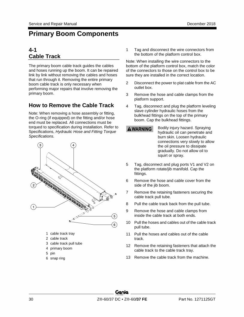
4-1 Cable Track The primary boom cable track guides the cables and hoses running up the boom. It can be repaired link by link without removing the cables and hoses that run through it. Removing the entire primary boom cable track is only necessary when performing major repairs that involve removing the primary boom.
How to Remove the Cable Track Note: When removing a hose assembly or fitting, the O-ring (if equipped) on the fitting and/or hose end must be replaced. All connections must be torqued to specification during installation. Refer to Specifications, Hydraulic Hose and Fitting Torque Specifications.
1 cable track tray 2 cable track 3 cable track pull tube 4 primary boom 5 pin 6 snap ring
1 Tag and disconnect the wire connectors from the bottom of the platform control box.
Note: When installing the wire connectors to the bottom of the platform control box, match the color of the connectors to those on the control box to be sure they are installed in the correct location.
2 Disconnect the power to plat cable from the AC outlet box.
3 Remove the hose and cable clamps from the platform support.
4 Tag, disconnect and plug the platform leveling slave cylinder hydraulic hoses from the bulkhead fittings on the top of the primary boom. Cap the bulkhead fittings.
Bodily injury hazard. Spraying hydraulic oil can penetrate and burn skin. Loosen hydraulic connections very slowly to allow the oil pressure to dissipate gradually. Do not allow oil to squirt or spray.
5 Tag, disconnect and plug ports V1 and V2 on the platform rotate/jib manifold. Cap the fittings.
6 Remove the hose and cable cover from the side of the jib boom.
7 Remove the retaining fasteners securing the cable track pull tube.
8 Pull the cable track back from the pull tube.
9 Remove the hose and cable clamps from inside the cable track at both ends.
10 Pull the hoses and cables out of the cable track pull tube.
11 Pull the hoses and cables out of the cable track.
12 Remove the retaining fasteners that attach the cable track to the cable track tray.
13 Remove the cable track from the machine.
December 2018 Service and Repair Manual
Primary Boom Components
Part No. 1271125GT Z®-60/37 DC • Z®-60/37 FE 31
How to R epair the C abl e Tr ack
How to Repair the Cable Track
Component damage hazard. The boom cable track can be damaged if it is twisted.
Note: A cable track repair kit is available through the Genie Service Parts Department.
1 Visually inspect the cable track and determine which 4 link section needs to be replaced.
2 Carefully remove the snap rings from each end of the damaged section of cable track.
3 Remove the retaining fasteners from the upper black rollers from the 4 link section of cable track to be replaced. Remove the rollers.
4 Lift up the hoses and cables and carefully remove the damaged 4 link section of cable track.
Component damage hazard. Hoses and cables can be damaged if they are kinked or pinched.
5 Remove the upper rollers from the replacement section of cable track.
6 Lift up the hoses and cables and carefully insert the new 4 link section of cable track.
Component damage hazard. Hoses and cables can be damaged if they are kinked or pinched.
Connect the ends of the replacement cable track section to the existing cable track using the snap rings.
7 Install the rollers onto the new section of cable track.
8 Operate the boom extend/retract function through a full cycle to ensure smooth operation of the new section of cable track.
4-2 Primary Boom
How to Remove the Primary Boom
Bodily injury hazard. This procedure requires specific repair skills, lifting equipment and a suitable workshop. Attempting this procedure without these skills and tools could result in death or serious injury and significant component damage. Dealer service is strongly recommended.
Note: When removing a hose assembly or fitting, the O-ring (if equipped) on the fitting and/or hose end must be replaced. All connections must be torqued to specification during installation. Refer to Specifications, Hydraulic Hose and Fitting Torque Specifications.
1 Remove the jib boom. Refer to Repair Procedure, How to Remove the Jib Boom.
2 Remove the cable track. Refer to Repair Procedure, How to Remove the Cable Track.
3 Raise the primary boom to the horizontal position.
4 Raise the secondary boom until the primary lift cylinder rod end pivot pin is above the upper secondary arm.
5 Attach lifting straps from a 5 ton / 5000 kg overhead crane to each end of the boom. Support the boom. Do not apply lifting pressure.
Service and Repair Manual December 2018
Primary Boom Components
32 Z®-60/37 DC • Z®-60/37 FE Part No. 1271125GT
6 Remove the retaining fasteners from the master cylinder rod-end pivot pin. Use a soft metal drift to remove the pin. Lower the master cylinder against the primary lift cylinder.
Component damage hazard. When lowering the master cylinder down, be sure not to damage the master cylinder hoses or fittings.
7 Tag, disconnect and plug the primary boom extension cylinder hydraulic hoses. Cap the fittings on the cylinder.
Bodily injury hazard. Spraying hydraulic oil can penetrate and burn skin. Loosen hydraulic connections very slowly to allow the oil pressure to dissipate gradually. Do not allow oil to squirt or spray.
8 Tag, disconnect and plug the hoses under the pivot end of the boom at the hose unions.
9 Using an overhead supporting device, attach a strap to the rod-end of the primary boom lift cylinder.
10 Remove the retaining fasteners from the primary boom lift cylinder rod-end pivot pin. Use a soft metal drift to remove the pin.
Crushing hazard. The boom lift cylinder and primary boom will fall if not properly supported.
11 Place a support block across the upper secondary arm and lower the lift cylinder on it.
12 Remove the lower cable and hose tray located under the primary boom and set it on a supporting device.
13 Remove the retaining fasteners from the primary boom pivot pin.
14 Remove the primary boom pivot pin with a soft metal drift, then carefully remove the primary boom from the machine and place it on a structure capable of supporting it.
Crushing hazard. The primary boom could become unbalanced and fall when removed from the machine if not properly attached to the overhead crane.
How to Disassembl e the Primar y Boom
How to Disassemble the Primary Boom Complete disassembly of the boom is only necessary if the outer or inner boom tube must be replaced. The extension cylinder can be removed without completely disassembling the boom. Refer to Repair Procedure, How to Remove the Primary Boom Extension Cylinder.
1 Remove the extension cylinder. Refer to Repair Procedure, How to Remove the Primary Boom Extension Cylinder.
2 Remove the primary boom. Refer to Repair Procedure, How to Remove the Primary Boom.
3 At the pivot end of the primary boom, remove the two side wear pads from the extension tube.
4 At the platform end of the primary boom, remove the upper and lower wear pad plates.
5 Support and slide the extension tube out of the boom tube.
Crushing hazard. The primary boom extension tube could become unbalanced and fall when removed from the primary boom tube if not properly supported.
Note: During removal, the overhead crane strap will need to be carefully adjusted for proper balancing.
December 2018 Service and Repair Manual
Primary Boom Components
Part No. 1271125GT Z®-60/37 DC • Z®-60/37 FE 33
4-3 Primary Boom Lift Cylinder The primary boom lift cylinder raises and lowers the primary boom. The primary boom lift cylinder is equipped with a counterbalance valve to prevent movement in the event of a hydraulic line failure.
How to Remove the Primary Boom Lift Cylinder
Bodily injury hazard. This procedure requires specific repair skills, lifting equipment and a suitable workshop. Attempting this procedure without these skills and tools could result in death or serious injury and significant component damage. Dealer service is strongly recommended.
Note: When removing a hose assembly or fitting, the O-ring (if equipped) on the fitting and/or hose end must be replaced. All connections must be torqued to specification during installation. Refer to Specifications, Hydraulic Hose and Fitting Torque Specifications.
1 Raise the primary boom to a horizontal position.
2 Raise the secondary boom until the upper secondary arm is above the compression arms.
3 Place a block across both compression arms. Lower the secondary boom until it just rest on the block. Do not rest the entire weight of the boom on the block.
4 Attach a 5 ton / 5000 kg overhead crane to the primary boom for support.
5 Raise the primary boom with the overhead crane slightly to take the pressure off the primary boom lift cylinder pivot pins.
6 Support the rod end and the barrel end of the primary boom lift cylinder with a second overhead crane or similar lifting device.
7 Tag, disconnect and plug the primary boom lift cylinder hydraulic hoses. Cap the fittings on the cylinder.
Bodily injury hazard. Spraying hydraulic oil can penetrate and burn skin. Loosen hydraulic connections very slowly to allow the oil pressure to dissipate gradually. Do not allow oil to squirt or spray.
8 Remove the retaining fasteners from the primary boom lift cylinder rod-end pivot pin. Use a soft metal drift to remove the pin.
Crushing hazard. The primary boom will fall if not properly supported when the primary boom rod-end pivot pin is removed.
9 Place a support block across the upper arm under the primary boom lift cylinder.
10 Lower the rod end of the lift cylinder onto the block. Protect the cylinder rod from damage.
Crushing hazard. The primary boom lift cylinder could become unbalanced and fall if not properly supported by the lifting device.
11 Remove the primary boom lift cylinder barrel-end pivot pin snap rings.
12 Use a soft metal drift to remove the pin. Carefully remove the primary boom lift cylinder from the machine.
Crushing hazard. The lift cylinder could become unbalanced and fall if not properly supported and secured to the lifting device.
Service and Repair Manual December 2018
Primary Boom Components
34 Z®-60/37 DC • Z®-60/37 FE Part No. 1271125GT
4-4 Primary Boom Extension Cylinder The primary boom extension cylinder extends and retracts the primary boom extension tube.The primary boom extension cylinder is equipped with counterbalance valves to prevent movement in the event of a hydraulic line failure.
How to Remove the Primary Boom Extension Cylinder
Bodily injury hazard. This procedure requires specific repair skills, lifting equipment and a suitable workshop. Attempting this procedure without these skills and tools could result in death or serious injury and significant component damage. Dealer service is strongly recommended.
Note: When removing a hose assembly or fitting, the O-ring (if equipped) on the fitting and/or hose end must be replaced. All connections must be torqued to specification during installation. Refer to Specifications, Hydraulic Hose and Fitting Torque Specifications.
1 Retract the primary boom. Raise the primary boom to a horizontal position.
2 At the pivot end of the boom, remove the cover from the end of the the #1 boom tube.
3 At the pivot end of the boom, remove the retaining fasteners and blocks securing the extend cylinder to the #2 boom tube through the access holes in the #1 boom tube.
4 At the pivot end of the boom, remove the retaining fasteners and blocks securing the extend cylinder to the #1 boom tube.
5 Tag, disconnect and plug the primary boom extension cylinder hydraulic hoses. Cap the fittings on the cylinder.
Bodily injury hazard. Spraying hydraulic oil can penetrate and burn skin. Loosen hydraulic connections very slowly to allow the oil pressure to dissipate gradually. Do not allow oil to squirt or spray.
Lift the extend cylinder block from the saddle. Support and slide the extension cylinder out of the primary boom.
Crushing hazard. The extension cylinder could fall when removed from the extension boom if not properly supported.
Component damage hazard. Be careful not to damage the counterbalance valves on the primary boom extension cylinder when removing the cylinder from the primary boom.
Component damage hazard. Hoses and cables can be damaged if the primary boom extension cylinder is dragged across them.
Note: Note the length of the cylinder after removal. The cylinder must be at the same length for installation.
December 2018 Service and Repair Manual
Primary Boom Components
Part No. 1271125GT Z®-60/37 DC • Z®-60/37 FE 35
4-5 Platform Leveling Master Cylinder The master cylinder acts as a pump for the slave cylinder. It’s part of the closed circuit hydraulic loop that keeps the platform level through the entire range of boom motion. The master cylinder is located at the base of the primary boom.
How to Remove the Platform Leveling Master Cylinder Note: When removing a hose assembly or fitting, the O-ring (if equipped) on the fitting and/or hose end must be replaced. All connections must be torqued to specification during installation. Refer to Specifications, Hydraulic Hose and Fitting Torque Specifications.
1 Raise the secondary boom until both the rod-end and barrel-end pivot pins on the master cylinder are accessible.
2 Use an overhead supporting device to support the platform. Do not apply lifting pressure.
3 Tag, disconnect and plug the master cylinder hydraulic hoses. Cap the fittings on the cylinder.
Bodily injury hazard. Spraying hydraulic oil can penetrate and burn skin. Loosen hydraulic connections very slowly to allow the oil pressure to dissipate gradually. Do not allow oil to squirt or spray.
4 Attach overhead crane or similar lifting device to the master cylinder.
5 Remove the retaining fasteners from the master cylinder barrel-end pivot pin.
6 Use a soft metal drift to remove the pin.
7 Remove the retaining fastener from the rod-end pivot pin.
8 Use a soft metal drift to remove the pin.
9 Remove the master cylinder from the machine.
Crushing hazard. The master cylinder could become unbalanced and fall if not properly attached to the overhead crane.
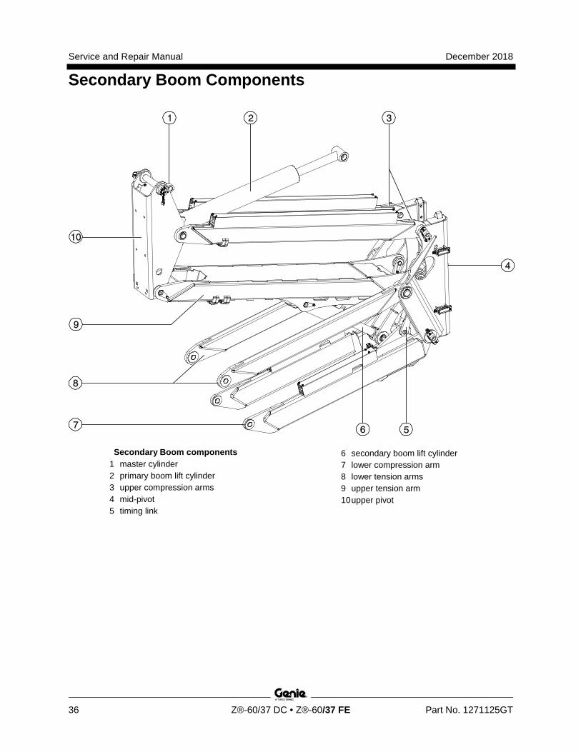
Service and Repair Manual December 2018
Secondary Boom Components
36 Z®-60/37 DC • Z®-60/37 FE Part No. 1271125GT
Secondary Boom components 1 master cylinder 2 primary boom lift cylinder 3 upper compression arms 4 mid-pivot 5 timing link
6 secondary boom lift cylinder 7 lower compression arm 8 lower tension arms 9 upper tension arm 10 upper pivot
December 2018 Service and Repair Manual
Secondary Boom Components
Part No. 1271125GT Z®-60/37 DC • Z®-60/37 FE 37
5-1 Secondary Boom Lift Cylinder There is one secondary boom lift cylinder incorporated in the structure of the secondary boom assembly. This cylinder requires hydraulic pressure to extend and retract. The secondary boom lift cylinder is equipped with counterbalance valves to prevent movement in the event of a hydraulic line failure.
How to Remove the Secondary Boom Lift Cylinder
Bodily injury hazard. This procedure requires specific repair skills, lifting equipment and a suitable workshop. Attempting this procedure without these skills and tools could result in death or serious injury and significant component damage. Dealer service is strongly recommended.
Note: When removing a hose assembly or fitting, the O-ring (if equipped) on the fitting and/or hose end must be replaced. All connections must be torqued to specification during installation. Refer to Specifications, Hydraulic Hose and Fitting Torque Specifications.
1 Raise the secondary boom until the barrel end pivot pins of the secondary lift cylinder clear the lower tension arms.
2 Attach a lifting strap from an overhead crane (5 ton / 5000 kg) to the pivot end of the primary boom for support. Do not apply lifting pressure.
Crushing hazard. The boom assembly can fall if not properly supported by the overhead crane.
Component damage hazard. Hoses and cables can be damaged if they are kinked or pinched.
3 Remove the pin retaining fasteners securing the barrel-end pivot pins of the secondary boom lift cylinder. Do not remove the pins.
4 Attach a strap from an overhead crane to the center of the secondary boom lift cylinder for support. Do not apply lifting pressure.
Crushing hazard. The secondary boom lift cylinder could become unbalanced and fall when removed from the machine if not properly attached to the overhead crane.
5 Use a slide hammer to remove the pivot pins.
6 Use auxiliary power to retract the cylinder.
7 Tag, disconnect and plug the hydraulic hoses from the secondary boom lift cylinder. Cap the fittings on the cylinder.
Bodily injury hazard. Spraying hydraulic oil can penetrate and burn skin. Loosen hydraulic connections very slowly to allow the oil pressure to dissipate gradually. Do not allow oil to squirt or spray.
Service and Repair Manual December 2018
Secondary Boom Components
38 Z®-60/37 DC • Z®-60/37 FE Part No. 1271125GT
8 Lower the cylinder onto the lower compression arm.
9 Remove the six fasteners securing the cap on the rod-end of the lift cylinder through the access hole of the lower compression arm.
Note: When installing the lift cylinder, torque the cap fasteners to 110 ft-lbs / 149 Nm dry.
10 Lift and move the cylinder towards the center of the machine enough to lower it down through the lower compression arm. Pull the cylinder towards the platform and remove it from the machine.
Crushing hazard. The secondary boom lift cylinder could become unbalanced and fall when removed from the machine if not properly attached to the overhead crane.
Component damage hazard. When removing a secondary boom lift cylinder from the machine, be careful not to damage the counterbalance valve at the barrel end of the cylinder.
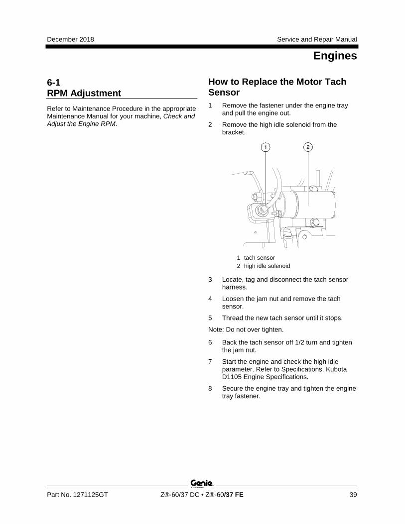
December 2018 Service and Repair Manual
Engines
Part No. 1271125GT Z®-60/37 DC • Z®-60/37 FE 39
6-1 RPM Adjustment Refer to Maintenance Procedure in the appropriate Maintenance Manual for your machine, Check and Adjust the Engine RPM.
How to R eplace the M otor Tach Sensor
How to Replace the Motor Tach Sensor 1 Remove the fastener under the engine tray
and pull the engine out.
2 Remove the high idle solenoid from the bracket.
1 tach sensor 2 high idle solenoid
3 Locate, tag and disconnect the tach sensor harness.
4 Loosen the jam nut and remove the tach sensor.
5 Thread the new tach sensor until it stops.
Note: Do not over tighten.
6 Back the tach sensor off 1/2 turn and tighten the jam nut.
7 Start the engine and check the high idle parameter. Refer to Specifications, Kubota D1105 Engine Specifications.
8 Secure the engine tray and tighten the engine tray fastener.
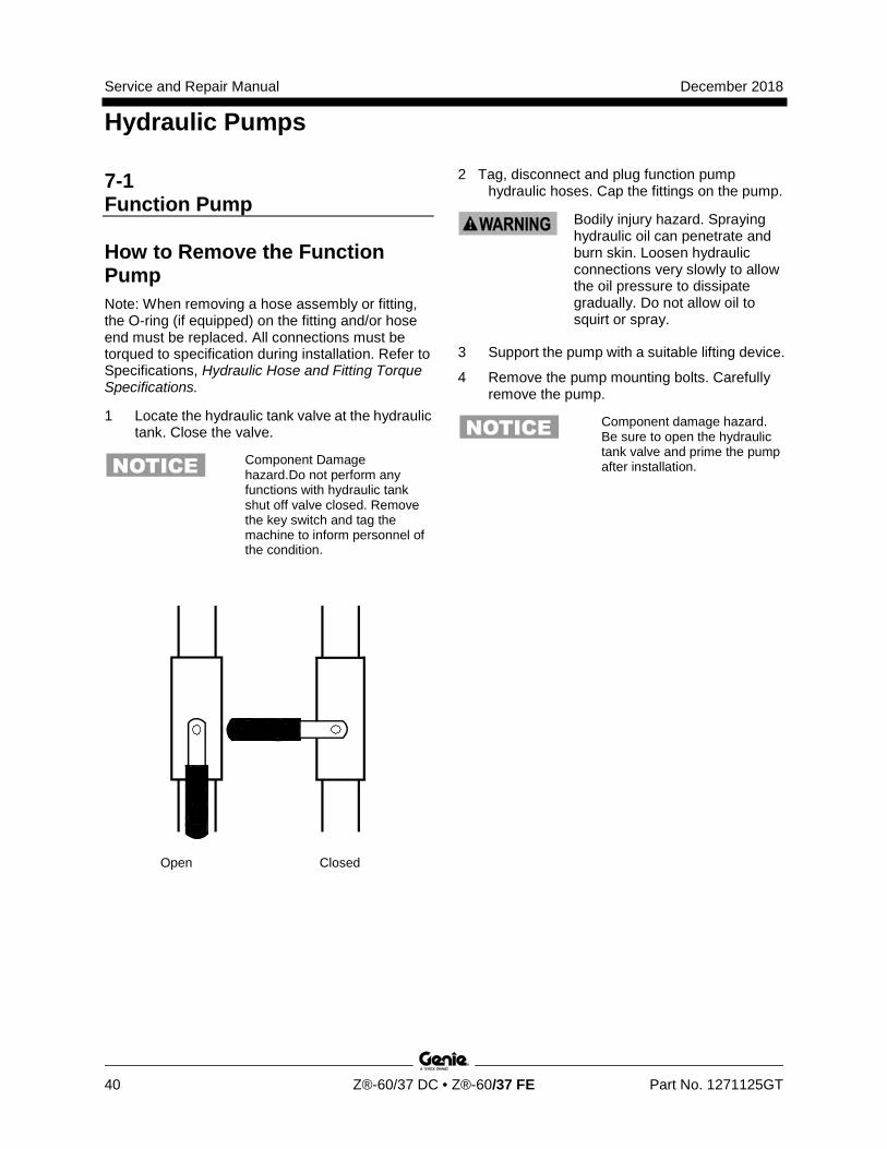
Service and Repair Manual December 2018
Hydraulic Pumps
40 Z®-60/37 DC • Z®-60/37 FE Part No. 1271125GT
7-1 Function Pump
How to Remove the Function Pump Note: When removing a hose assembly or fitting, the O-ring (if equipped) on the fitting and/or hose end must be replaced. All connections must be torqued to specification during installation. Refer to Specifications, Hydraulic Hose and Fitting Torque Specifications.
1 Locate the hydraulic tank valve at the hydraulic tank. Close the valve.
Component Damage hazard.Do not perform any functions with hydraulic tank shut off valve closed. Remove the key switch and tag the machine to inform personnel of the condition.
Open Closed
2 Tag, disconnect and plug function pump hydraulic hoses. Cap the fittings on the pump.
Bodily injury hazard. Spraying hydraulic oil can penetrate and burn skin. Loosen hydraulic connections very slowly to allow the oil pressure to dissipate gradually. Do not allow oil to squirt or spray.
3 Support the pump with a suitable lifting device.
4 Remove the pump mounting bolts. Carefully remove the pump.
Component damage hazard. Be sure to open the hydraulic tank valve and prime the pump after installation.
December 2018 Service and Repair Manual
Hydraulic Pumps
Part No. 1271125GT Z®-60/37 DC • Z®-60/37 FE 41
How to C heck the Function Pump C alibr ati on
How to Check the Function Pump Calibration Pump efficiency is calibrated automatically but must be verified after a new pump installation and before performing any boom speed calibrations. Refer to Repair Procedures, Calibration Process Steps. This procedure determines the number of revolutions that are required to create a determined amount of flow for both the large and small gear pumps.
Note: Start this procedure with the secondary boom in the stowed position and primary boom at or above horizontal. Position the machine in a suitable location with sufficient vertical space. Refer to Navigation Menus, Settings Menu.
Note: Primary and secondary angle sensors must be functional and calibrated. Refer to Repair Procedures, How to Calibrate Booms Angle Sensors.
1 Pull out the red Emergency Stop button to the on position at both the ground and platform controls.
Note: If the unit is equipped with the engine option, set the machine to DC mode.
2 Move and hold the drive enable toggle switch in the right direction while holding steer in the right direction.
3 When the display leaves SYSTEM READY mode, release the drive enable toggle switch and the steer joystick.
4 Momentarily activate steer in the right direction until SETTINGS is shown on the display.
5 Momentarily activate the drive enable toggle switch in the right direction until you see the VALVE AND SENSOR SETTINGS screen.
6 Momentarily activate the drive enable toggle switch in the right direction until CALIBRATE TILT SENSOR is shown on the display.
7 Continue to momentarily active the steer in the right direction until LARGE & SMALL PUMP EFFICIENCY is shown on the display.
8 Momentarily activate the drive enable toggle switch to enter LARGE & SMALL PUMP EFFICIENCY menu.
9 Perform the secondary boom up function.
Result: A one second pulse alarm will sound indicating a successful large pump efficiency calibration. The display will indicate pump efficiency in %.
10 Raise the secondary boom to the halfway position.
11 Perform the secondary boom down function.
Result: A one second pulse alarm will sound indicating a successful small pump efficiency calibration. The display will indicate pump efficiency in %.
To exit programming mode:
12 Move and hold the drive enable toggle in the left position until the display returns to SYSTEM READY mode.

Service and Repair Manual December 2018
Manifolds
42 Z®-60/37 DC • Z®-60/37 FE Part No. 1271125GT
This page intentionally left blank
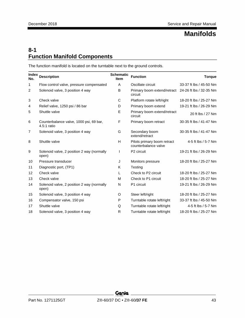
December 2018 Service and Repair Manual
Manifolds
Part No. 1271125GT Z®-60/37 DC • Z®-60/37 FE 43
8-1 Function Manifold Components The function manifold is located on the turntable next to the ground controls.
Index No. Description Schematic
Item Function Torque
1 Flow control valve, pressure compensated A Oscillate circuit 33-37 ft lbs / 45-50 Nm 2 Solenoid valve, 3 position 4 way B Primary boom extend/retract
circuit 24-26 ft lbs / 32-35 Nm
3 Check valve C Platform rotate left/right 18-20 ft lbs / 25-27 Nm 4 Relief valve, 1250 psi / 86 bar D Primary boom extend 19-21 ft lbs / 26-29 Nm 5 Shuttle valve E Primary boom extend/retract
circuit 20 ft lbs / 27 Nm
6 Counterbalance valve, 1000 psi, 69 bar, 4.5:1 ratio
F Primary boom retract 30-35 ft lbs / 41-47 Nm
7 Solenoid valve, 3 position 4 way G Secondary boom extend/retract
30-35 ft lbs / 41-47 Nm
8 Shuttle valve H Pilots primary boom retract counterbalance valve
4-5 ft lbs / 5-7 Nm
9 Solenoid valve, 2 position 2 way (normally open)
I P2 circuit 19-21 ft lbs / 26-29 Nm
10 Pressure transducer J Monitors pressure 18-20 ft lbs / 25-27 Nm 11 Diagnostic port, (TP1) K Testing 12 Check valve L Check to P2 circuit 18-20 ft lbs / 25-27 Nm 13 Check valve M Check to P1 circuit 18-20 ft lbs / 25-27 Nm 14 Solenoid valve, 2 position 2 way (normally
open) N P1 circuit 19-21 ft lbs / 26-29 Nm
15 Solenoid valve, 3 position 4 way O Steer left/right 18-20 ft lbs / 25-27 Nm 16 Compensator valve, 150 psi P Turntable rotate left/right 33-37 ft lbs / 45-50 Nm 17 Shuttle valve Q Turntable rotate left/right 4-5 ft lbs / 5-7 Nm 18 Solenoid valve, 3 position 4 way R Turntable rotate left/right 18-20 ft lbs / 25-27 Nm
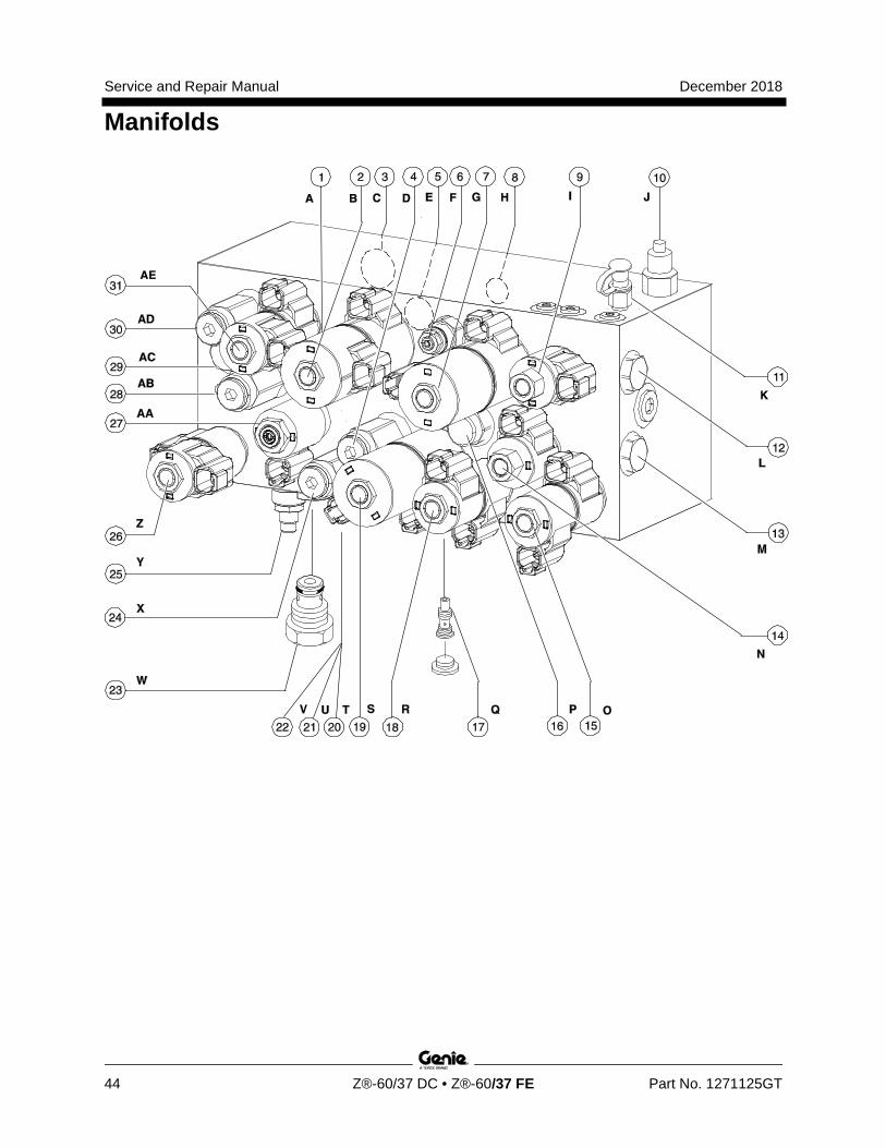
Service and Repair Manual December 2018
Manifolds
44 Z®-60/37 DC • Z®-60/37 FE Part No. 1271125GT
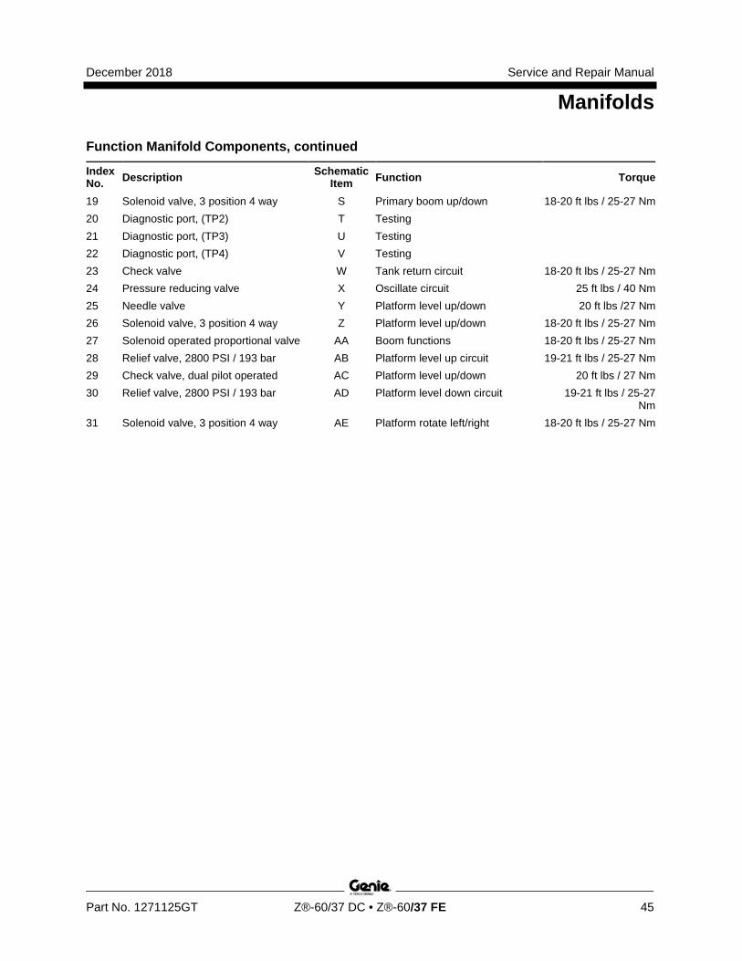
December 2018 Service and Repair Manual
Manifolds
Part No. 1271125GT Z®-60/37 DC • Z®-60/37 FE 45
Function Manifold Components, continued
Index No. Description Schematic
Item Function Torque
19 Solenoid valve, 3 position 4 way S Primary boom up/down 18-20 ft lbs / 25-27 Nm 20 Diagnostic port, (TP2) T Testing 21 Diagnostic port, (TP3) U Testing 22 Diagnostic port, (TP4) V Testing 23 Check valve W Tank return circuit 18-20 ft lbs / 25-27 Nm 24 Pressure reducing valve X Oscillate circuit 25 ft lbs / 40 Nm 25 Needle valve Y Platform level up/down 20 ft lbs /27 Nm 26 Solenoid valve, 3 position 4 way Z Platform level up/down 18-20 ft lbs / 25-27 Nm 27 Solenoid operated proportional valve AA Boom functions 18-20 ft lbs / 25-27 Nm 28 Relief valve, 2800 PSI / 193 bar AB Platform level up circuit 19-21 ft lbs / 25-27 Nm 29 Check valve, dual pilot operated AC Platform level up/down 20 ft lbs / 27 Nm 30 Relief valve, 2800 PSI / 193 bar AD Platform level down circuit 19-21 ft lbs / 25-27
Nm 31 Solenoid valve, 3 position 4 way AE Platform rotate left/right 18-20 ft lbs / 25-27 Nm
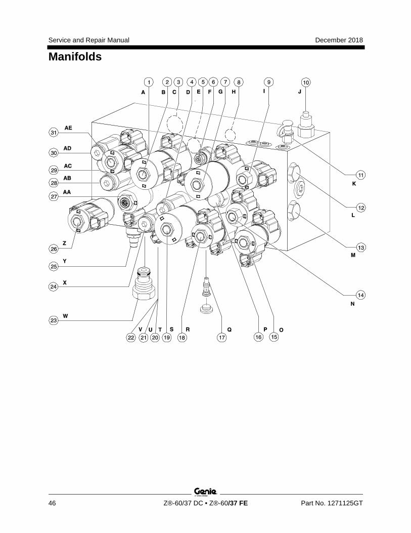
Service and Repair Manual December 2018
Manifolds
46 Z®-60/37 DC • Z®-60/37 FE Part No. 1271125GT
December 2018 Service and Repair Manual
Manifolds
Part No. 1271125GT Z®-60/37 DC • Z®-60/37 FE 47
8-2 Valve Adjustments - Function Manifold How to Adj ust the Pr oportional Reli ef Val ve and H ydraulic Pr essure Sensor
How to Adjust the Proportional Relief Valve and Hydraulic Pressure Sensor Note: Perform this procedure with the machine in the stowed position.
1 Connect a 0 to 5000 PSI / 0 to 350 bar pressure gauge to test port 1 on top of the function manifold.
2 Turn the key switch to Ground control. Pull out the platform red Emergency Stop button to the on position and pull out the ground control red Emergency stop button to the on position.
3 To enter the pressure sensor calibration mode, momentarily activate the ground control function enable switch three times within 5 seconds of pulling the red Emergency Stop button at the ground controls.
The pump motor activates and a green light will begin flashing on the TCON controller.
Note: The procedure will time out if any step is not completed within 90 seconds or terminate if the function enable switch is activated.
4 Simultaneously activate the platform level toggle switch until the pressure gauge reads 1000 PSI / 69 bar. The platform level toggle up increases pressure, platform level down decreases pressure.
5 Simultaneously activate the platform rotate toggle switch to store the value.
Result: The control system will continue to the next calibration procedure value - (3000 PSI / 207 bar).
6 Simultaneously activate the platform level toggle switch until the pressure gauge reads 3000 PSI / 207 bar. The platform level toggle up increases pressure, platform level down decreases pressure.
7 Simultaneously activate the platform rotate toggle switch to save the value.
Result: The control system will automatically continue to the next procedure, calibrate and save for the remaining values: 2500 PSI / 172 bar, 2000 PSI / 138 bar, and 500 PSI / 34 bar. A one second pulse alarm will indicate the calibration procedure is complete.
8 Remove the pressure gauge.
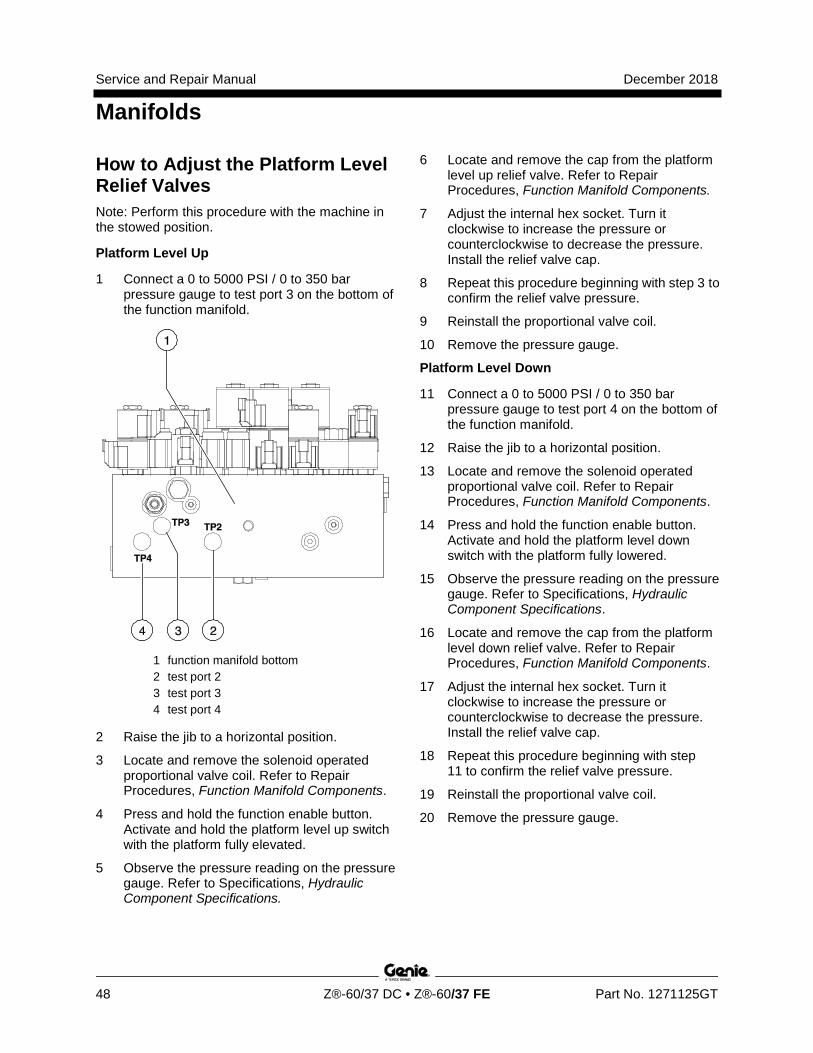
Service and Repair Manual December 2018
Manifolds
48 Z®-60/37 DC • Z®-60/37 FE Part No. 1271125GT
How to Adj ust the Pl atfor m Level U p R elief Val ve
How to Adjust the Platform Level Relief Valves Note: Perform this procedure with the machine in the stowed position.
Platform Level Up
1 Connect a 0 to 5000 PSI / 0 to 350 bar pressure gauge to test port 3 on the bottom of the function manifold.
1 function manifold bottom 2 test port 2 3 test port 3 4 test port 4
2 Raise the jib to a horizontal position.
3 Locate and remove the solenoid operated proportional valve coil. Refer to Repair Procedures, Function Manifold Components.
4 Press and hold the function enable button. Activate and hold the platform level up switch with the platform fully elevated.
5 Observe the pressure reading on the pressure gauge. Refer to Specifications, Hydraulic Component Specifications.
6 Locate and remove the cap from the platform level up relief valve. Refer to Repair Procedures, Function Manifold Components.
7 Adjust the internal hex socket. Turn it clockwise to increase the pressure or counterclockwise to decrease the pressure. Install the relief valve cap.
8 Repeat this procedure beginning with step 3 to confirm the relief valve pressure.
9 Reinstall the proportional valve coil.
10 Remove the pressure gauge.
Platform Level Down
11 Connect a 0 to 5000 PSI / 0 to 350 bar pressure gauge to test port 4 on the bottom of the function manifold.
12 Raise the jib to a horizontal position.
13 Locate and remove the solenoid operated proportional valve coil. Refer to Repair Procedures, Function Manifold Components.
14 Press and hold the function enable button. Activate and hold the platform level down switch with the platform fully lowered.
15 Observe the pressure reading on the pressure gauge. Refer to Specifications, Hydraulic Component Specifications.
16 Locate and remove the cap from the platform level down relief valve. Refer to Repair Procedures, Function Manifold Components.
17 Adjust the internal hex socket. Turn it clockwise to increase the pressure or counterclockwise to decrease the pressure. Install the relief valve cap.
18 Repeat this procedure beginning with step 11 to confirm the relief valve pressure.
19 Reinstall the proportional valve coil.
20 Remove the pressure gauge.
December 2018 Service and Repair Manual
Manifolds
Part No. 1271125GT Z®-60/37 DC • Z®-60/37 FE 49
How to Adj ust the Pri mar y Boom Extend R elief Val ve
How to Adjust the Primary Boom Extend Relief Valve Note: Perform this procedure with the machine in the stowed position.
1 Connect a 0 to 5000 PSI / 0 to 350 bar pressure gauge to test port 1 on top of the function manifold.
2 Raise the boom to a horizontal position.
3 Locate and remove the solenoid operated proportional valve coil. Refer to Repair Procedures, Function Manifold Components.
4 Press and hold the function enable button. Activate and hold the primary boom extend switch with the boom fully extended.
5 Observe the pressure reading on the pressure gauge. Refer to Specifications, Hydraulic Component Specifications.
6 Locate and remove the cap from the primary boom extend relief valve. Refer to Repair Procedures, Function Manifold Components.
7 Remove the pressure gauge.
8 Adjust the internal hex socket. Turn it clockwise to increase the pressure or counterclockwise to decrease the pressure. Install the relief valve cap.
9 Repeat this procedure beginning with step 4 to confirm the relief valve pressure.
10 Reinstall the proportional valve coil.
11 Remove the pressure gauge.
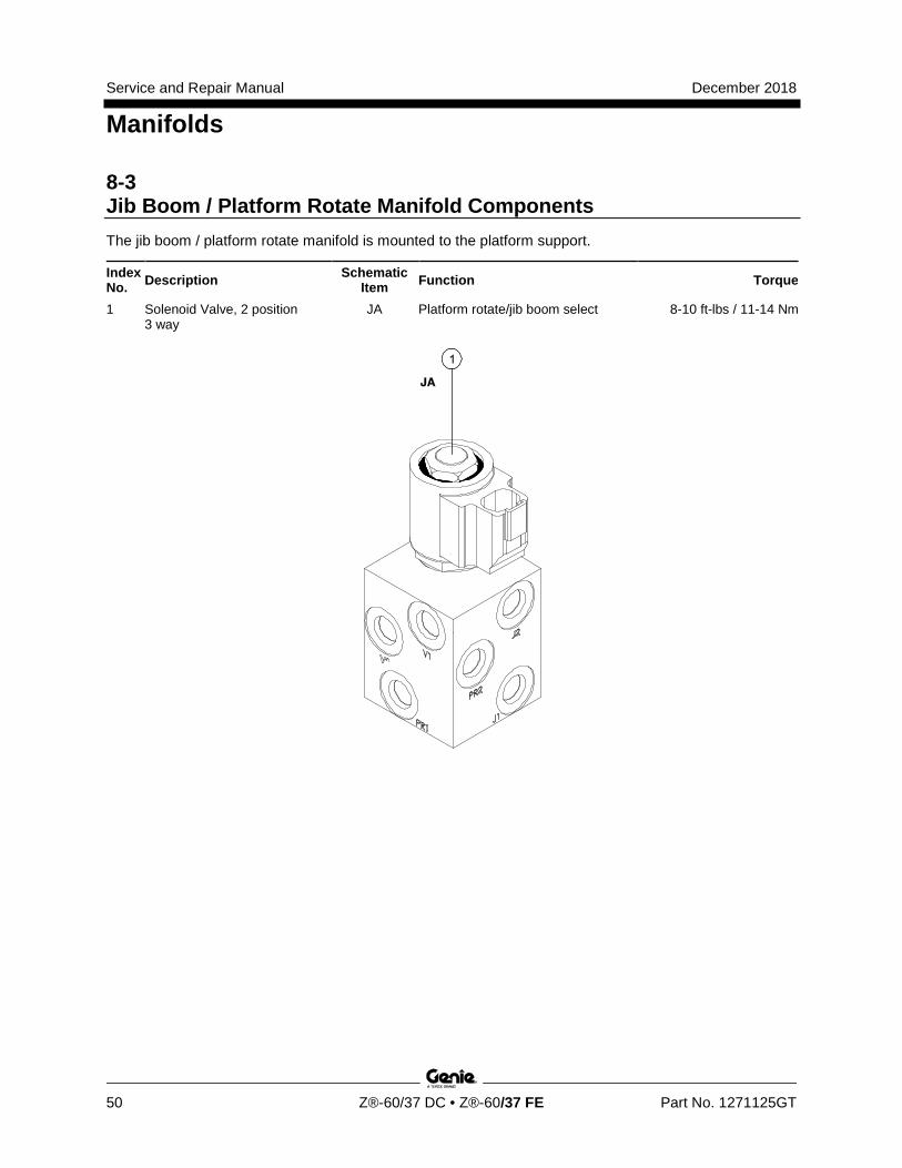
Service and Repair Manual December 2018
Manifolds
50 Z®-60/37 DC • Z®-60/37 FE Part No. 1271125GT
8-3 Jib Boom / Platform Rotate Manifold Components The jib boom / platform rotate manifold is mounted to the platform support.
Index No. Description Schematic
Item Function Torque
1 Solenoid Valve, 2 position 3 way
JA Platform rotate/jib boom select 8-10 ft-lbs / 11-14 Nm
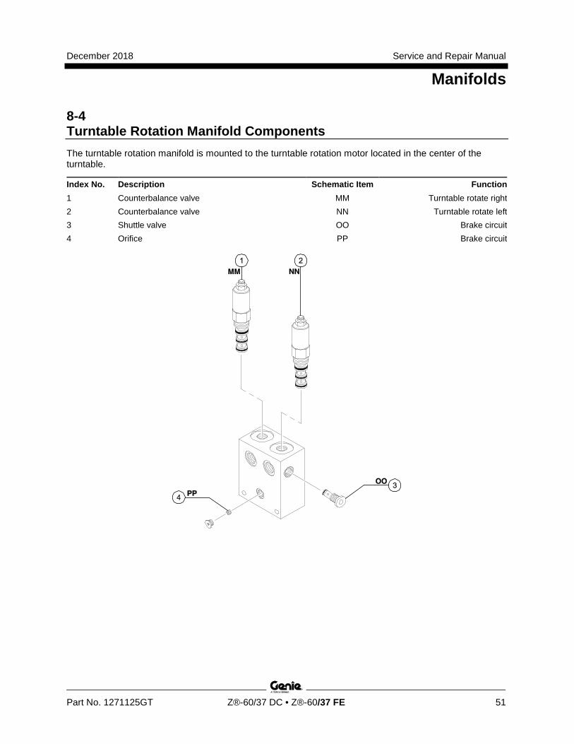
December 2018 Service and Repair Manual
Manifolds
Part No. 1271125GT Z®-60/37 DC • Z®-60/37 FE 51
8-4 Turntable Rotation Manifold Components The turntable rotation manifold is mounted to the turntable rotation motor located in the center of the turntable.
Index No. Description Schematic Item Function 1 Counterbalance valve MM Turntable rotate right 2 Counterbalance valve NN Turntable rotate left 3 Shuttle valve OO Brake circuit 4 Orifice PP Brake circuit
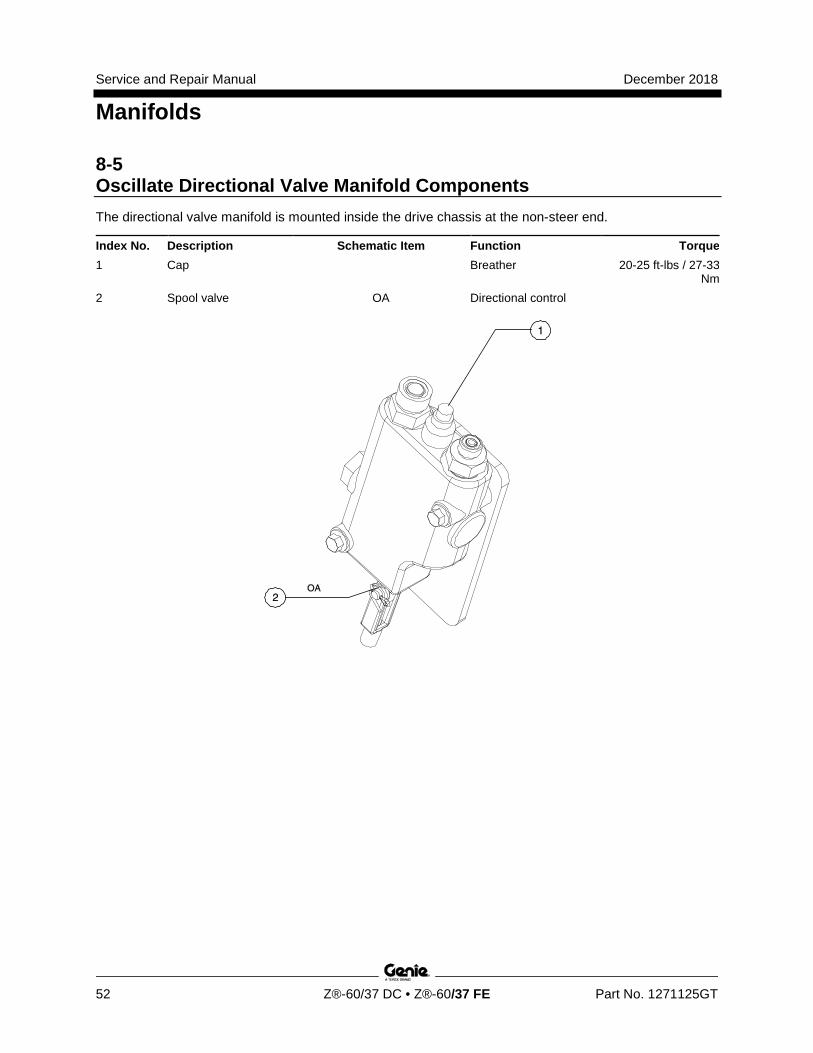
Service and Repair Manual December 2018
Manifolds
52 Z®-60/37 DC • Z®-60/37 FE Part No. 1271125GT
8-5 Oscillate Directional Valve Manifold Components The directional valve manifold is mounted inside the drive chassis at the non-steer end.
Index No. Description Schematic Item Function Torque 1 Cap Breather 20-25 ft-lbs / 27-33
Nm 2 Spool valve OA Directional control
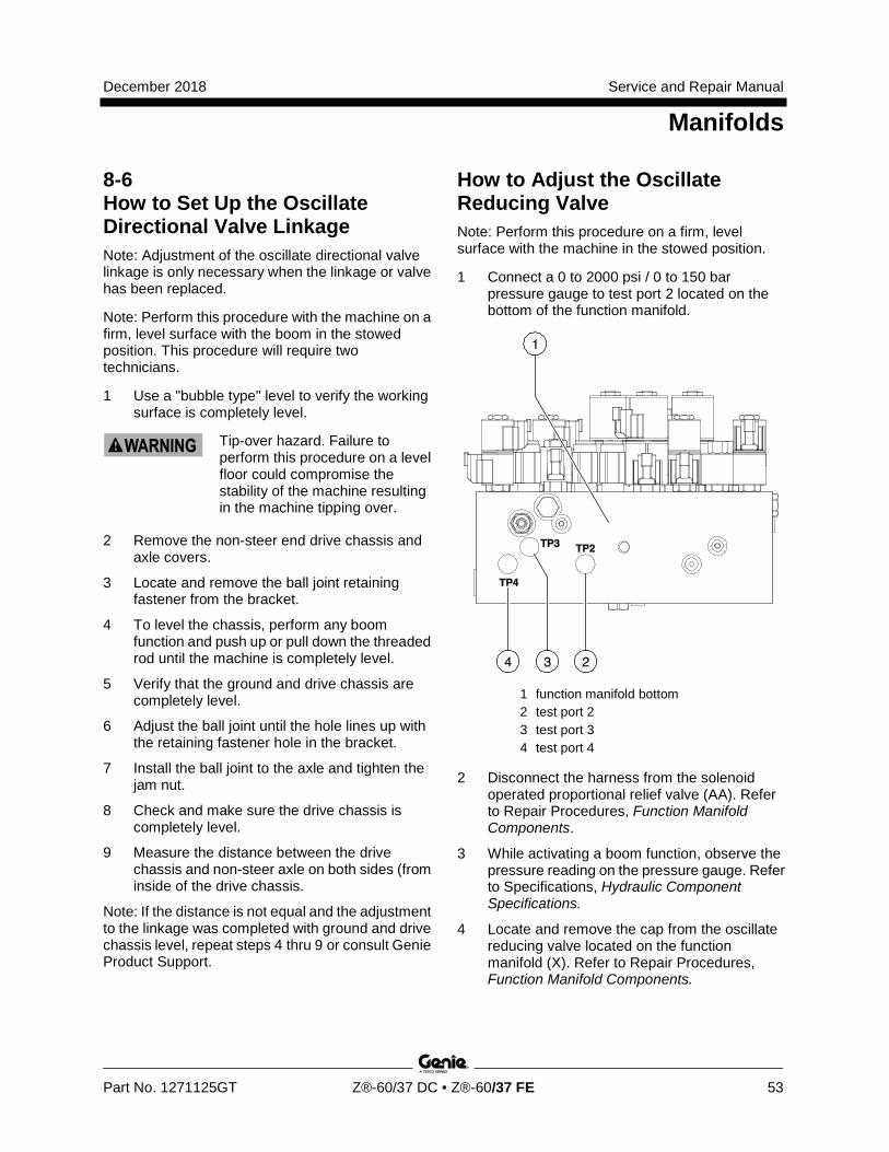
December 2018 Service and Repair Manual
Manifolds
Part No. 1271125GT Z®-60/37 DC • Z®-60/37 FE 53
8-6 How to Set Up the Oscillate Directional Valve Linkage Note: Adjustment of the oscillate directional valve linkage is only necessary when the linkage or valve has been replaced.
Note: Perform this procedure with the machine on a firm, level surface with the boom in the stowed position. This procedure will require two technicians.
1 Use a "bubble type" level to verify the working surface is completely level.
Tip-over hazard. Failure to perform this procedure on a level floor could compromise the stability of the machine resulting in the machine tipping over.
2 Remove the non-steer end drive chassis and axle covers.
3 Locate and remove the ball joint retaining fastener from the bracket.
4 To level the chassis, perform any boom function and push up or pull down the threaded rod until the machine is completely level.
5 Verify that the ground and drive chassis are completely level.
6 Adjust the ball joint until the hole lines up with the retaining fastener hole in the bracket.
7 Install the ball joint to the axle and tighten the jam nut.
8 Check and make sure the drive chassis is completely level.
9 Measure the distance between the drive chassis and non-steer axle on both sides (from inside of the drive chassis.
Note: If the distance is not equal and the adjustment to the linkage was completed with ground and drive chassis level, repeat steps 4 thru 9 or consult Genie Product Support.
How to Adj ust the Oscill ate R educing Val ve
How to Adjust the Oscillate Reducing Valve Note: Perform this procedure on a firm, level surface with the machine in the stowed position.
1 Connect a 0 to 2000 psi / 0 to 150 bar pressure gauge to test port 2 located on the bottom of the function manifold.
1 function manifold bottom 2 test port 2 3 test port 3 4 test port 4
2 Disconnect the harness from the solenoid operated proportional relief valve (AA). Refer to Repair Procedures, Function Manifold Components.
3 While activating a boom function, observe the pressure reading on the pressure gauge. Refer to Specifications, Hydraulic Component Specifications.
4 Locate and remove the cap from the oscillate reducing valve located on the function manifold (X). Refer to Repair Procedures, Function Manifold Components.
Service and Repair Manual December 2018
Manifolds
54 Z®-60/37 DC • Z®-60/37 FE Part No. 1271125GT
5 Adjust the internal hex socket. Turn it clockwise to increase the pressure or counterclockwise to decrease the pressure. Install the relief valve cap.
Tip-over hazard. Do not adjust the relief valve higher than specified.
6 Repeat this procedure beginning with step 3 to confirm the reducing valve pressure.
7 Remove the pressure gauge.
8-7 Valve Coils
How to Test a Coil A properly functioning coil provides an electromotive force which operates the solenoid valve. Critical to normal operation is continuity within the coil that provides this force field.
Since coil resistance is sensitive to temperature, resistance values outside specification can produce erratic operation. When coil resistance decreases below specification, amperage increases. As resistance rises above specification, voltage increases.
While valves may operate when coil resistance is outside specification, maintaining coils within specification will help ensure proper valve function over a wide range of operating temperatures.
Electrocution/burn hazard. Contact with electrically charged circuits could result in death or serious injury. Remove all rings, watches and other jewelry.
1 Tag and disconnect the wiring from the coil to be tested.
2 Test the coil resistance.
Result: The resistance should be within specification, plus or minus 30%.
Result: If the resistance is not within specification, plus or minus 30%, replace the coil.
Valve Coil Resistance Specification Note: The following coil resistance specifications are at an ambient temperature of 68°F / 20°C. As valve coil resistance is sensitive to changes in air temperature, the coil resistance will typically increase or decrease by 4% for each 18°F / 10°C that your air temperature increases or decreases from 68°F / 20°C. Refer to Specifications, Manifold Component Specifications for valve coil specifications.
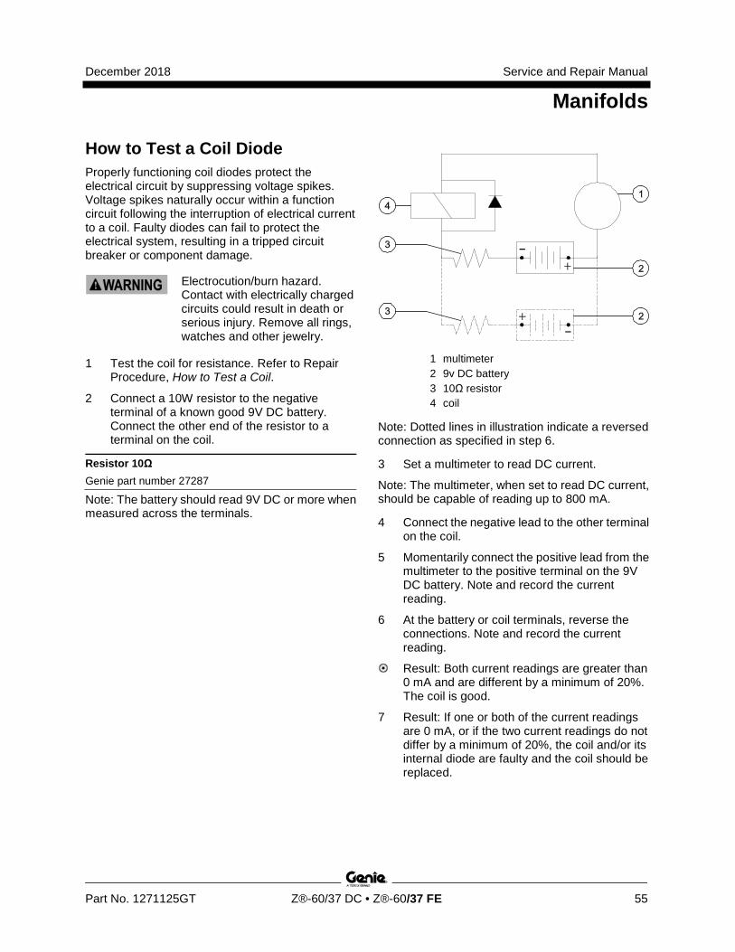
December 2018 Service and Repair Manual
Manifolds
Part No. 1271125GT Z®-60/37 DC • Z®-60/37 FE 55
How to Test a Coil Di ode
How to Test a Coil Diode Properly functioning coil diodes protect the electrical circuit by suppressing voltage spikes. Voltage spikes naturally occur within a function circuit following the interruption of electrical current to a coil. Faulty diodes can fail to protect the electrical system, resulting in a tripped circuit breaker or component damage.
Electrocution/burn hazard. Contact with electrically charged circuits could result in death or serious injury. Remove all rings, watches and other jewelry.
1 Test the coil for resistance. Refer to Repair Procedure, How to Test a Coil.
2 Connect a 10W resistor to the negative terminal of a known good 9V DC battery. Connect the other end of the resistor to a terminal on the coil.
Resistor 10Ω Genie part number 27287
Note: The battery should read 9V DC or more when measured across the terminals.
1 multimeter 2 9v DC battery 3 10Ω resistor 4 coil
Note: Dotted lines in illustration indicate a reversed connection as specified in step 6.
3 Set a multimeter to read DC current.
Note: The multimeter, when set to read DC current, should be capable of reading up to 800 mA.
4 Connect the negative lead to the other terminal on the coil.
5 Momentarily connect the positive lead from the multimeter to the positive terminal on the 9V DC battery. Note and record the current reading.
6 At the battery or coil terminals, reverse the connections. Note and record the current reading.
Result: Both current readings are greater than 0 mA and are different by a minimum of 20%. The coil is good.
7 Result: If one or both of the current readings are 0 mA, or if the two current readings do not differ by a minimum of 20%, the coil and/or its internal diode are faulty and the coil should be replaced.
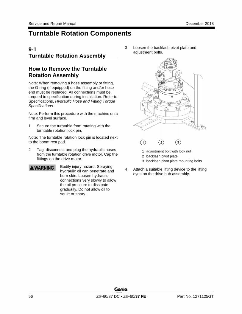
Service and Repair Manual December 2018
Turntable Rotation Components
56 Z®-60/37 DC • Z®-60/37 FE Part No. 1271125GT
9-1 Turntable Rotation Assembly
How to Remove the Turntable Rotation Assembly Note: When removing a hose assembly or fitting, the O-ring (if equipped) on the fitting and/or hose end must be replaced. All connections must be torqued to specification during installation. Refer to Specifications, Hydraulic Hose and Fitting Torque Specifications.
Note: Perform this procedure with the machine on a firm and level surface.
1 Secure the turntable from rotating with the turntable rotation lock pin.
Note: The turntable rotation lock pin is located next to the boom rest pad.
2 Tag, disconnect and plug the hydraulic hoses from the turntable rotation drive motor. Cap the fittings on the drive motor.
Bodily injury hazard. Spraying hydraulic oil can penetrate and burn skin. Loosen hydraulic connections very slowly to allow the oil pressure to dissipate gradually. Do not allow oil to squirt or spray.
3 Loosen the backlash pivot plate and adjustment bolts.
1 adjustment bolt with lock nut 2 backlash pivot plate 3 backlash pivot plate mounting bolts
4 Attach a suitable lifting device to the lifting eyes on the drive hub assembly.
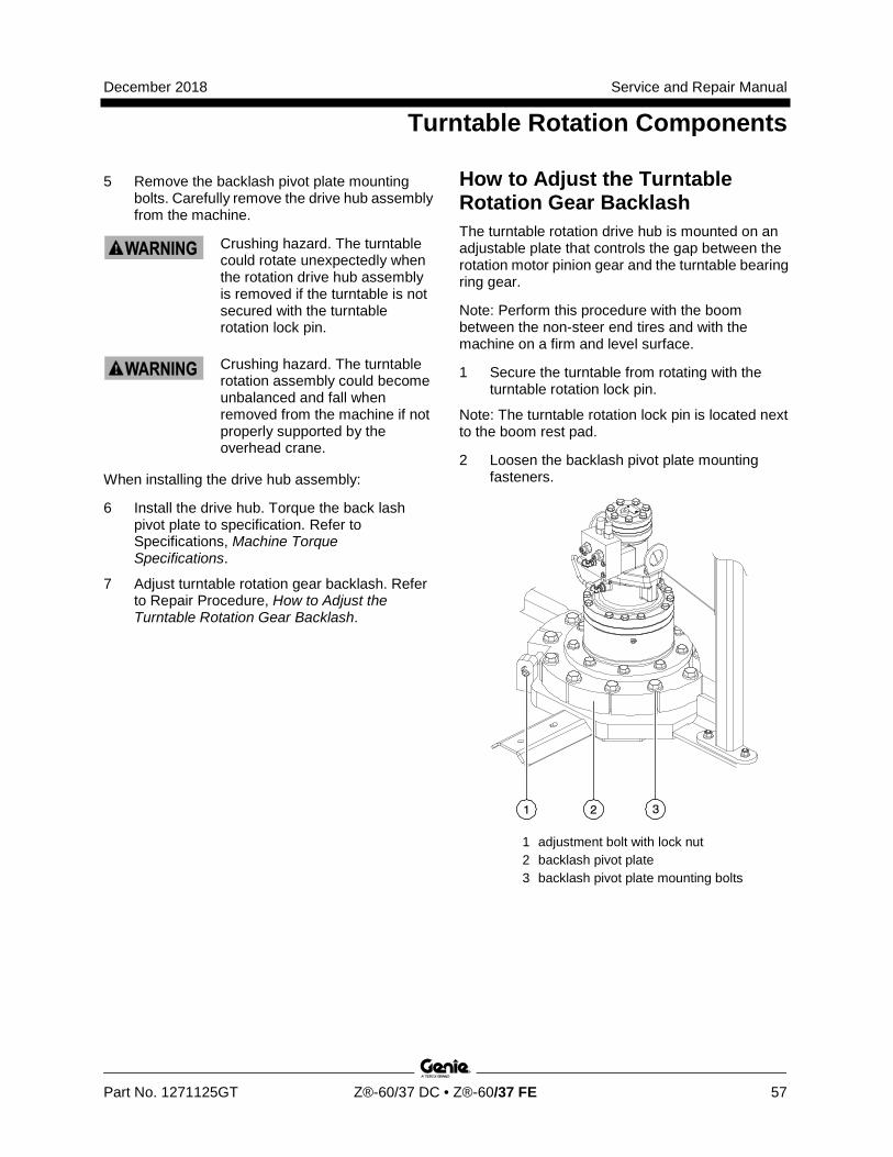
December 2018 Service and Repair Manual
Turntable Rotation Components
Part No. 1271125GT Z®-60/37 DC • Z®-60/37 FE 57
5 Remove the backlash pivot plate mounting bolts. Carefully remove the drive hub assembly from the machine.
Crushing hazard. The turntable could rotate unexpectedly when the rotation drive hub assembly is removed if the turntable is not secured with the turntable rotation lock pin.
Crushing hazard. The turntable rotation assembly could become unbalanced and fall when removed from the machine if not properly supported by the overhead crane.
When installing the drive hub assembly:
6 Install the drive hub. Torque the back lash pivot plate to specification. Refer to Specifications, Machine Torque Specifications.
7 Adjust turntable rotation gear backlash. Refer to Repair Procedure, How to Adjust the Turntable Rotation Gear Backlash.
How to Adjust the Turntable Rotation Gear Backlash The turntable rotation drive hub is mounted on an adjustable plate that controls the gap between the rotation motor pinion gear and the turntable bearing ring gear.
Note: Perform this procedure with the boom between the non-steer end tires and with the machine on a firm and level surface.
1 Secure the turntable from rotating with the turntable rotation lock pin.
Note: The turntable rotation lock pin is located next to the boom rest pad.
2 Loosen the backlash pivot plate mounting fasteners.
1 adjustment bolt with lock nut 2 backlash pivot plate 3 backlash pivot plate mounting bolts
Service and Repair Manual December 2018
Turntable Rotation Components
58 Z®-60/37 DC • Z®-60/37 FE Part No. 1271125GT
3 Push the backlash pivot plate towards the turntable as far as possible (this will push the rotation gear into the turntable bearing ring gear).
4 Loosen the lock nut on the adjustment bolt.
5 Turn the adjustment bolt clockwise until it contacts the backlash pivot plate.
6 Turn the adjustment bolt 1/2 turn counterclockwise. Tighten the lock nut on the adjustment bolt.
7 Rotate the backlash pivot plate away from the turntable until it contacts the adjustment bolt. Then torque the mounting fasteners on the backlash pivot plate to specification. Refer to Specifications, Machine Torque Specifications.
8 Rotate the turntable through an entire rotation. Check for tight spots that could cause binding. Readjust if necessary.
9-2 How to Replace the Universal Tilt Sensor (UTS) This machine has a dual axis angle-sensing device called the Universal Tilt Sensor (UTS). It is mounted on the turntable to monitor and communicate ground angle relative to gravity via CAN bus. Should the turntable be tilted at the Allowable Tilt Angle or greater an alarm will sound at both the turntable and the platform. If not calibrated, the machine will only drive in the stowed configuration in turtle mode.
Note: Perform this procedure on a firm, level surface with the machine in the stowed position.
1 Push in the red Emergency Stop button to the off position.
2 Tag and disconnect the harness from the tilt sensor.
Note: Record the X and Y axis orientation of the tilt sensor.
3 Remove the fasteners securing the tilt sensor to the turntable.
4 Secure the new tilt sensor using the existing fasteners removed in step 3. Tighten the fasteners.
5 Calibrate the tilt sensor. Refer to Repair Procedure, How to Calibrate the Universal Tilt Sensor.
December 2018 Service and Repair Manual
Turntable Rotation Components
Part No. 1271125GT Z®-60/37 DC • Z®-60/37 FE 59
How to C alibr ate the Uni versal Tilt Sensor
How to Calibrate the Universal Tilt Sensor (UTS) Note: Perform this procedure on a firm, level surface with the machine in the stowed position. Refer to Navigation Menus, Settings Menu.
1 Pull out the red Emergency Stop button to the on position at both the ground and platform controls. Turn the key switch to platform control.
2 Move and hold the drive enable toggle switch in the right direction while holding steer in the right direction.
3 When the display leaves SYSTEM READY mode, release the drive enable toggle switch and the steer joystick.
Result: The display will show FAULTS.
4 Momentarily activate steer in the right direction until SETTINGS is shown on the display.
5 Momentarily activate the drive enable toggle switch in the right direction until you see the VALVE AND SENSOR SETTINGS screen.
6 Momentarily activate the drive enable toggle switch in the right direction until you see the TILT SENSOR CALIBRATE screen.
7 Momentarily activate the drive enable toggle switch in the right direction to enter the TILT SENSOR CALIBRATE screen.
8 Momentarily activate the drive enable toggle switch to save the X and Y axis values.
Result: An audible alarm will sound for one second indicating a successful calibration.
To exit programming mode:
9 Move and hold the drive enable toggle in the left position until the display returns to SYSTEM READY mode.
Service and Repair Manual December 2018
Axle Components
60 Z®-60/37 DC • Z®-60/37 FE Part No. 1271125GT
10-1 Oscillating Axle Cylinders The oscillating axle cylinders extend and retract between the drive chassis and the oscillating axle. The cylinders are equipped with counterbalance valves to prevent movement in the event of a hydraulic line failure. The valves are not adjustable.
How to Remove an Oscillating Axle Cylinder Note: Perform this procedure with the machine on a firm, level surface with the boom in the stowed position.
Note: When removing a hose assembly or fitting, the O-ring (if equipped) on the fitting and/or hose end must be replaced. All connections must be torqued to specification during installation. Refer to Specifications, Hydraulic Hose and Fitting Torque Specifications.
1 Rotate the turntable until the boom is between the steer tires or tracks.
2 Tag, disconnect and plug the oscillating axle cylinder hydraulic hoses. Cap the fittings on the oscillate cylinder.
Bodily injury hazard. Spraying hydraulic oil can penetrate and burn skin. Loosen hydraulic connections very slowly to allow the oil pressure to dissipate gradually. Do not allow oil to squirt or spray.
3 Remove the pin retaining fasteners from the rod-end pivot pin. Use a soft metal drift to remove the pin.
4 Attach a lifting strap from an overhead crane to the barrel end of the oscillating cylinder.
5 Remove the pin retaining fasteners from the barrel-end pivot pin. Use a soft metal drift to remove the pin.
6 Remove the oscillate cylinder from the machine.
Crushing hazard. The oscillate cylinder may become unbalanced and fall when removed from the machine if not properly attached to the overhead crane.
December 2018 Service and Repair Manual
Axle Components
Part No. 1271125GT Z®-60/37 DC • Z®-60/37 FE 61
10-2 How to Remove the Steer Cylinder 1 Adjust the steer tires so they are in a straight
driving position.
2 Turn the key switch to the off position.
3 Push in the red Emergency Stop buttons to the off position at both the ground and platform controls.
4 Remove the drive chassis cover at the steer end of the machine.
5 Remove the cable clamp securing the steer sensor cable to the chassis.
6 Tag and disconnect the steer sensor harness from the main harness.
7 Tag, disconnect and plug the hydraulic hoses from the steer cylinder. Cap the fittings on the cylinder.
Bodily injury hazard. Spraying hydraulic oil can penetrate and burn skin. Loosen hydraulic connections very slowly to allow the oil pressure to dissipate gradually. Do not allow oil to squirt or spray.
8 Remove the rue ring and clevis pin from each end of the cylinder.
9 Remove the cylinder from the machine.
Component damage hazard. Hoses and cables can be damaged if they are kinked or pinched.
How to C alibr ate the Steer Angle Sensor
How to Calibrate the Steer Angle Sensor Note: Perform this procedure on a firm, level surface with the machine in the stowed position. Refer to Navigation Menus, Settings Menu.
1 Turn the key switch to platform control.
2 Pull out the red Emergency Stop button to the on position at both the ground and platform controls.
3 Adjust the steer wheels so they are pointing straight ahead, in line with the non-steer wheels. Release the foot switch.
4 Move and hold the drive enable toggle switch in the right direction while holding steer in the right direction.
5 When the display leaves SYSTEM READY mode, release the drive enable toggle switch and the steer joystick.
Result: The display will show FAULTS.
6 Momentarily activate steer right until SETTINGS is shown on the display.
7 Momentarily activate the steer right direction until you see the DRIVE SETTINGS screen.
8 Momentarily activate the drive enable toggle switch in the right direction until you see the STEER SENSOR CAL screen.
9 Momentarily activate the drive enable toggle switch in the right direction.
Result: The display will show steer sensor value in mV and ENABLE will appear at the bottom of the screen.
10 Momentarily activate the drive enable toggle switch in the right direction to save calibrate steer center.
Result: The alarm will sound and the mV value flashes to indicate the setting has been saved.
To exit programming mode:
11 Move and hold the drive enable toggle in the left position until the display returns to SYSTEM READY mode.

Service and Repair Manual December 2018
62 Z®-60/37 DC • Z®-60/37 FE Part No. 1271125GT
This page intentionally left blank.
December 2018 Service and Repair Manual
Fault Codes
Part No. 1271125GT Z®-60/37 DC • Z®-60/37 FE 63
Section 4 Faul t Codes
Observe and Obey: R Troubleshooting and repair procedures shall be
completed by a person trained and qualified on the repair of this machine
R Immediately tag and remove from service a damaged or malfunctioning machine.
R Repair any machine damage or malfunction before operating the machine.
R Unless otherwise specified, perform each procedure with the machine in the following configuration:
· Machine parked on a firm, level surface
· Key switch in the off position with the key removed
· The red Emergency Stop button in the off position at both the ground and platform controls
· Wheels chocked
· All external AC power supply disconnected from the machine
· Boom in the stowed position
· Turntable secured with the turntable rotation lock
· Welder disconnected from the machine (if equipped with the weld cable to platform option)
Before Troubleshooting: R Read, understand and obey the safety rules
and operating instructions in the appropriate operator's manual on your machine.
R Be sure that all necessary tools and test equipment are available and ready for use.
R Read each appropriate fault code thoroughly. Attempting short cuts may produce hazardous conditions.
R Be aware of the following hazards and follow generally accepted safe workshop practices.
Electrocution/burn hazard. Contact with electrically charged circuits could result in death or serious injury. Remove all rings, watches and other jewelry.
Note: Two persons will be required to safely perform some troubleshooting procedures.
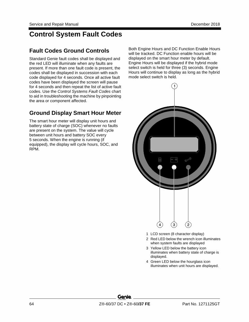
Service and Repair Manual December 2018
Control System Fault Codes
64 Z®-60/37 DC • Z®-60/37 FE Part No. 1271125GT
Fault Codes Ground Controls Standard Genie fault codes shall be displayed and the red LED will illuminate when any faults are present. If more than one fault code is present, the codes shall be displayed in succession with each code displayed for 4 seconds. Once all active fault codes have been displayed the screen will pause for 4 seconds and then repeat the list of active fault codes. Use the Control Systems Fault Codes chart to aid in troubleshooting the machine by pinpointing the area or component affected.
Ground Display Smart Hour Meter The smart hour meter will display unit hours and battery state of charge (SOC) whenever no faults are present on the system. The value will cycle between unit hours and battery SOC every 5 seconds. When the engine is running (if equipped), the display will cycle hours, SOC, and RPM.
Both Engine Hours and DC Function Enable Hours will be tracked. DC Function enable hours will be displayed on the smart hour meter by default. Engine Hours will be displayed if the hybrid mode select switch is held for three (3) seconds. Engine Hours will continue to display as long as the hybrid mode select switch is held.
1 LCD screen (8 character display) 2 Red LED below the wrench icon illuminates
when system faults are displayed 3 Yellow LED below the battery icon
illuminates when battery state of charge is displayed.
4 Green LED below the hourglass icon illuminates when unit hours are displayed.
December 2018 Service and Repair Manual
Control System Fault Codes
Part No. 1271125GT Z®-60/37 DC • Z®-60/37 FE 65
How to Retrieve Control System Fault Codes from the Platform Controls At least one fault code is present when the alarm at the platform controls produces one short beep every 30 seconds. Refer to Navigation Menus, Faults Menu.
1 Turn the key switch to platform control.
2 Pull out the red Emergency Stop button to the on position at both the ground and platform controls.
3 Do not press down the foot switch.
4 Move and hold the drive enable toggle switch in the right direction and hold steer in the right direction.
5 When the display leaves SYSTEM READY mode, release the drive enable toggle switch and steer.
Result: The display will show FAULTS.
To access active faults list:
6 Momentarily activate the drive enable toggle switch in the right direction until ACTIVE FAULTS is shown on the display.
7 Momentarily activate the drive enable toggle switch in the right direction to access the active fault codes.
8 Activate steer in the right direction to scroll through the fault codes. Fault codes will be listed in order 1 through 16.
To access fault history list:
9 Momentarily activate the drive enable toggle switch in the right direction until ACTIVE FAULTS is shown on the display.
10 Activate the steer rocker switch in the right direction until FAULT HISTORY is shown on the display.
11 Momentarily activate the drive enable toggle switch in the right direction to access the fault history list codes.
12 Activate the steer rocker switch in the right direction to scroll through the fault codes. Fault codes will be listed in order 1 through 16.
13 Refer to the Control System Fault Codes chart to aid in troubleshooting the machine by pinpointing the area or component affected
To clear fault history
14 Momentarily activate the drive enable toggle switch in the right direction until ACTIVE FAULTS is shown on the display.
15 Activate steer in the right direction until CLEAR FAULTS HISTORY is shown on the display.
16 Momentarily activate the drive enable toggle switch in the right direction to enter CLEAR FAULTS HISTORY.
Result: CLEAR FAULT HISTORY? NO will appear on the display.
17 Momentarily activate drive enable right to enter menu.
Result: Enable will appear at the bottom of the display.
18 Activate steer in the right direction to change the display from NO to YES.
19 Activate the drive enable toggle switch in the right direction to accept the change.
Result: The alarm will sound for one second. All fault history listings and counters will be cleared.
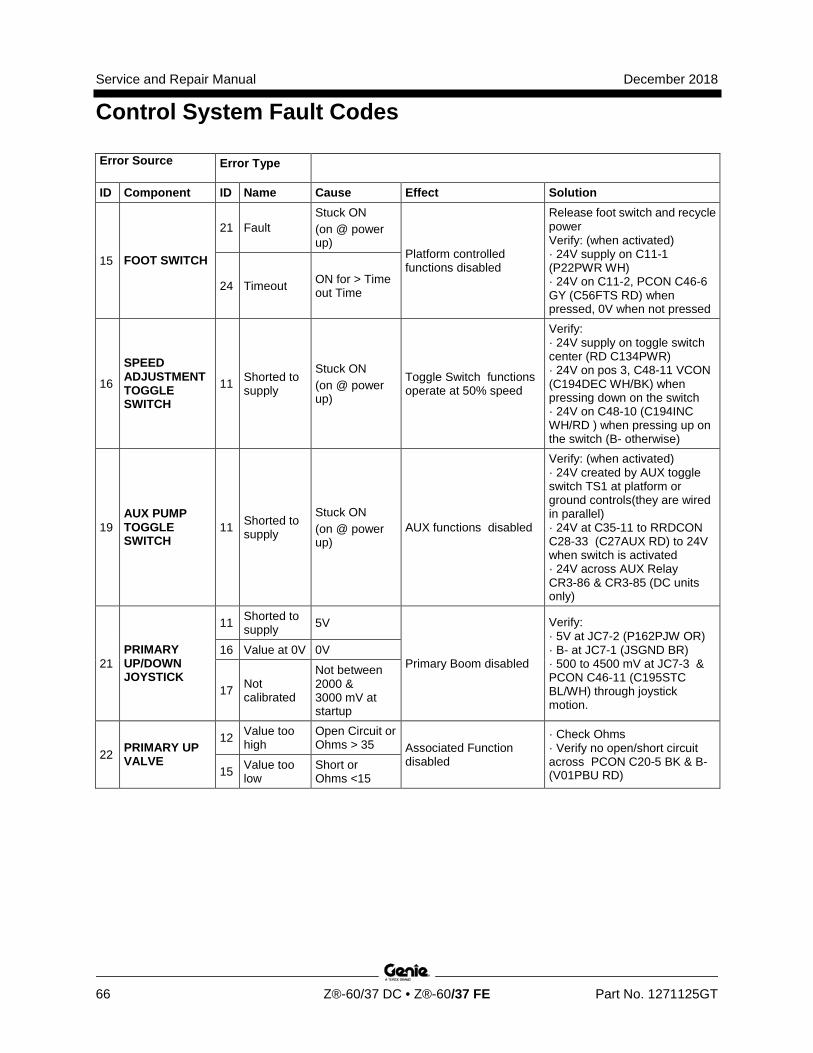
Service and Repair Manual December 2018
Control System Fault Codes
66 Z®-60/37 DC • Z®-60/37 FE Part No. 1271125GT
Error Source Error Type
ID Component ID Name Cause Effect Solution
15 FOOT SWITCH
21 Fault Stuck ON (on @ power up)
Platform controlled functions disabled
Release foot switch and recycle power Verify: (when activated) · 24V supply on C11-1 (P22PWR WH) · 24V on C11-2, PCON C46-6 GY (C56FTS RD) when pressed, 0V when not pressed
24 Timeout ON for > Timeout Time
16
SPEED ADJUSTMENT TOGGLE SWITCH
11 Shorted to supply
Stuck ON (on @ power up)
Toggle Switch functions operate at 50% speed
Verify: · 24V supply on toggle switch center (RD C134PWR) · 24V on pos 3, C48-11 VCON (C194DEC WH/BK) when pressing down on the switch · 24V on C48-10 (C194INC WH/RD ) when pressing up on the switch (B- otherwise)
19 AUX PUMP TOGGLE SWITCH
11 Shorted to supply
Stuck ON (on @ power up)
AUX functions disabled
Verify: (when activated) · 24V created by AUX toggle switch TS1 at platform or ground controls(they are wired in parallel) · 24V at C35-11 to RRDCON C28-33 (C27AUX RD) to 24V when switch is activated · 24V across AUX Relay CR3-86 & CR3-85 (DC units only)
21 PRIMARY UP/DOWN JOYSTICK
11 Shorted to supply 5V
Primary Boom disabled
Verify: · 5V at JC7-2 (P162PJW OR) · B- at JC7-1 (JSGND BR) · 500 to 4500 mV at JC7-3 & PCON C46-11 (C195STC BL/WH) through joystick motion.
16 Value at 0V 0V
17 Not calibrated
Not between 2000 & 3000 mV at startup
22 PRIMARY UP VALVE
12 Value too high
Open Circuit or Ohms > 35 Associated Function
disabled
· Check Ohms · Verify no open/short circuit across PCON C20-5 BK & B- (V01PBU RD) 15 Value too
low Short or Ohms <15
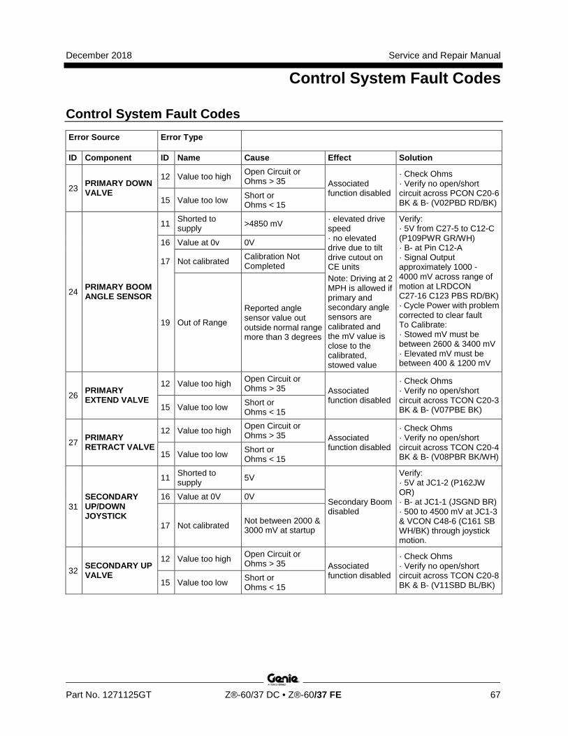
December 2018 Service and Repair Manual
Control System Fault Codes
Part No. 1271125GT Z®-60/37 DC • Z®-60/37 FE 67
Control System Fault Codes Error Source Error Type
ID Component ID Name Cause Effect Solution
23 PRIMARY DOWN VALVE
12 Value too high Open Circuit or Ohms > 35 Associated
function disabled
· Check Ohms · Verify no open/short circuit across PCON C20-6 BK & B- (V02PBD RD/BK) 15 Value too low Short or
Ohms < 15
24 PRIMARY BOOM ANGLE SENSOR
11 Shorted to supply >4850 mV · elevated drive
speed · no elevated drive due to tilt drive cutout on CE units Note: Driving at 2 MPH is allowed if primary and secondary angle sensors are calibrated and the mV value is close to the calibrated, stowed value
Verify: · 5V from C27-5 to C12-C (P109PWR GR/WH) · B- at Pin C12-A · Signal Output approximately 1000 - 4000 mV across range of motion at LRDCON C27-16 C123 PBS RD/BK) · Cycle Power with problem corrected to clear fault To Calibrate: · Stowed mV must be between 2600 & 3400 mV · Elevated mV must be between 400 & 1200 mV
16 Value at 0v 0V
17 Not calibrated Calibration Not Completed
19 Out of Range
Reported angle sensor value out outside normal range more than 3 degrees
26 PRIMARY EXTEND VALVE
12 Value too high Open Circuit or Ohms > 35 Associated
function disabled
· Check Ohms · Verify no open/short circuit across TCON C20-3 BK & B- (V07PBE BK) 15 Value too low Short or
Ohms < 15
27 PRIMARY RETRACT VALVE
12 Value too high Open Circuit or Ohms > 35 Associated
function disabled
· Check Ohms · Verify no open/short circuit across TCON C20-4 BK & B- (V08PBR BK/WH) 15 Value too low Short or
Ohms < 15
31 SECONDARY UP/DOWN JOYSTICK
11 Shorted to supply 5V
Secondary Boom disabled
Verify: · 5V at JC1-2 (P162JW OR) · B- at JC1-1 (JSGND BR) · 500 to 4500 mV at JC1-3 & VCON C48-6 (C161 SB WH/BK) through joystick motion.
16 Value at 0V 0V
17 Not calibrated Not between 2000 & 3000 mV at startup
32 SECONDARY UP VALVE
12 Value too high Open Circuit or Ohms > 35 Associated
function disabled
· Check Ohms · Verify no open/short circuit across TCON C20-8 BK & B- (V11SBD BL/BK) 15 Value too low Short or
Ohms < 15
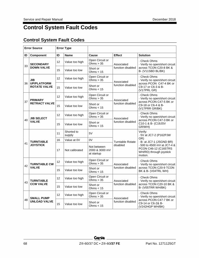
Service and Repair Manual December 2018
Control System Fault Codes
68 Z®-60/37 DC • Z®-60/37 FE Part No. 1271125GT
Control System Fault Codes Error Source Error Type
ID Component ID Name Cause Effect Solution
33 SECONDARY DOWN VALVE
12 Value too high Open Circuit or Ohms > 35 Associated
function disabled
· Check Ohms · Verify no open/short circuit across TCON C20-8 BK & B- (V11SBD BL/BK) 15 Value too low Short or
Ohms < 15
36 JIB UP/PLATFORM ROTATE VALVE
12 Value too high Open Circuit or Ohms > 35 Associated
function disabled
· Check Ohms · Verify no open/short circuit across PCON C47-4 BK or C9-17 or C6-3 & B- (V17PRL GR)
15 Value too low Short or Ohms < 15
37 PRIMARY RETRACT VALVE
12 Value too high Open Circuit or Ohms > 35 Associated
function disabled
· Check Ohms · Verify no open/short circuit across PCON C47-5 BK or C9-18 or C6-4 & B- (V17PRR GR/BK)
15 Value too low Short or Ohms < 15
40 JIB SELECT VALVE
12 Value too high Open Circuit or Ohms > 35 Associated
function disabled
· Check Ohms · Verify no open/short circuit across PCON C47-3 BK or C10-1 & B- (C19JSV GR/WH)
15 Value too low Short or Ohms < 15
41 TURNTABLE JOYSTICK
11 Shorted to supply 5V
Turntable Rotate disabled
Verify: · 5V at JC7-2 (P162PJW OR) · B- at JC7-1 (JSGND BR) · 500 to 4500 mV at JC7-4 & PCON C46-12 (C165TRS WH/RD) through joystick motion.
16 Value at 0V 0V
17 Not calibrated Not between 2000 & 3000 mV at startup
42 TURNTABLE CW VALVE
12 Value too high Open Circuit or Ohms > 35 Associated
function disabled
· Check Ohms · Verify no open/short circuit across TCON C20-9 TCON BK & B- (V04TRL WH) 15 Value too low Short or
Ohms < 15
43 TURNTABLE CCW VALVE
12 Value too high Open Circuit or Ohms > 35 Associated
function disabled
· Check Ohms · Verify no open/short circuit across TCON C20-10 BK & B- (V05TRR WH/BK) 15 Value too low Short or
Ohms < 15
48 SMALL PUMP UNLOAD VALVE
12 Value too high Open Circuit or Ohms > 35 Associated
function disabled
· Check Ohms · Verify no open/short circuit across PCON C47-7 BK or C9-14 or C6-2& B- (V242HGP WH/BK)
15 Value too low Short or Ohms < 15
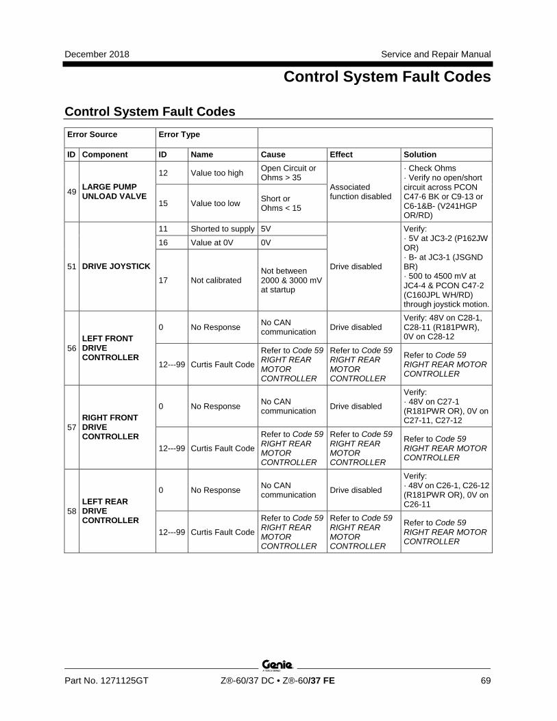
December 2018 Service and Repair Manual
Control System Fault Codes
Part No. 1271125GT Z®-60/37 DC • Z®-60/37 FE 69
Control System Fault Codes Error Source Error Type
ID Component ID Name Cause Effect Solution
49 LARGE PUMP UNLOAD VALVE
12 Value too high Open Circuit or Ohms > 35
Associated function disabled
· Check Ohms · Verify no open/short circuit across PCON C47-6 BK or C9-13 or C6-1&B- (V241HGP OR/RD)
15 Value too low Short or Ohms < 15
51 DRIVE JOYSTICK
11 Shorted to supply 5V
Drive disabled
Verify: · 5V at JC3-2 (P162JW OR) · B- at JC3-1 (JSGND BR) · 500 to 4500 mV at JC4-4 & PCON C47-2 (C160JPL WH/RD) through joystick motion.
16 Value at 0V 0V
17 Not calibrated Not between 2000 & 3000 mV at startup
56 LEFT FRONT DRIVE CONTROLLER
0 No Response No CAN communication Drive disabled
Verify: 48V on C28-1, C28-11 (R181PWR), 0V on C28-12
12---99 Curtis Fault Code
Refer to Code 59 RIGHT REAR MOTOR CONTROLLER
Refer to Code 59 RIGHT REAR MOTOR CONTROLLER
Refer to Code 59 RIGHT REAR MOTOR CONTROLLER
57 RIGHT FRONT DRIVE CONTROLLER
0 No Response No CAN communication Drive disabled
Verify: · 48V on C27-1 (R181PWR OR), 0V on C27-11, C27-12
12---99 Curtis Fault Code
Refer to Code 59 RIGHT REAR MOTOR CONTROLLER
Refer to Code 59 RIGHT REAR MOTOR CONTROLLER
Refer to Code 59 RIGHT REAR MOTOR CONTROLLER
58 LEFT REAR DRIVE CONTROLLER
0 No Response No CAN communication Drive disabled
Verify: · 48V on C26-1, C26-12 (R181PWR OR), 0V on C26-11
12---99 Curtis Fault Code
Refer to Code 59 RIGHT REAR MOTOR CONTROLLER
Refer to Code 59 RIGHT REAR MOTOR CONTROLLER
Refer to Code 59 RIGHT REAR MOTOR CONTROLLER
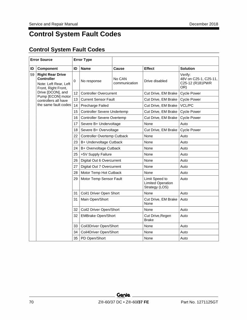
Service and Repair Manual December 2018
Control System Fault Codes
70 Z®-60/37 DC • Z®-60/37 FE Part No. 1271125GT
Control System Fault Codes Error Source Error Type
ID Component ID Name Cause Effect Solution 59 Right Rear Drive
Controller Note: Left Rear, Left Front, Right Front, Drive [DCON], and Pump [ECON] motor controllers all have the same fault codes
0 No response No CAN communication Drive disabled
Verify: 48V on C25-1, C25-11, C25-12 (R181PWR OR)
12 Controller Overcurrent Cut Drive, EM Brake Cycle Power
13 Current Sensor Fault Cut Drive, EM Brake Cycle Power
14 Precharge Failed Cut Drive, EM Brake VCL/PC
15 Controller Severe Undertemp Cut Drive, EM Brake Cycle Power
16 Controller Severe Overtemp Cut Drive, EM Brake Cycle Power
17 Severe B+ Undervoltage None Auto
18 Severe B+ Overvoltage Cut Drive, EM Brake Cycle Power
22 Controller Overtemp Cutback None Auto
23 B+ Undervoltage Cutback None Auto
24 B+ Overvoltage Cutback None Auto
25 +5V Supply Failure None Auto
26 Digital Out 6 Overcurrent None Auto
27 Digital Out 7 Overcurrent None Auto
28 Motor Temp Hot Cutback None Auto
29 Motor Temp Sensor Fault Limit Speed to Limited Operation Strategy (LOS)
Auto
31 Coil1 Driver Open Short None Auto
31 Main Open/Short Cut Drive, EM Brake None
Auto
32 Coil2 Driver Open/Short None Auto
32 EMBrake Open/Short Cut Drive,Regen Brake
Auto
33 Coil3Driver Open/Short None Auto
34 Coil4Driver Open/Short None Auto
35 PD Open/Short None Auto
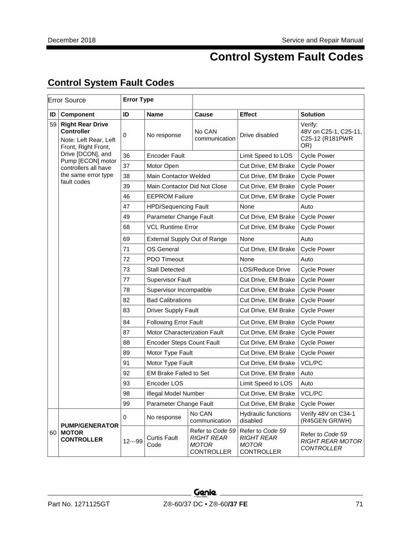
December 2018 Service and Repair Manual
Control System Fault Codes
Part No. 1271125GT Z®-60/37 DC • Z®-60/37 FE 71
Control System Fault Codes
Error Source Error Type
ID Component ID Name Cause Effect Solution 59 Right Rear Drive
Controller Note: Left Rear, Left Front, Right Front, Drive [DCON], and Pump [ECON] motor controllers all have the same error type fault codes
0 No response No CAN communication Drive disabled
Verify: 48V on C25-1, C25-11, C25-12 (R181PWR OR)
36 Encoder Fault Limit Speed to LOS Cycle Power
37 Motor Open Cut Drive, EM Brake Cycle Power
38 Main Contactor Welded Cut Drive, EM Brake Cycle Power
39 Main Contactor Did Not Close Cut Drive, EM Brake Cycle Power
46 EEPROM Failure Cut Drive, EM Brake Cycle Power
47 HPD/Sequencing Fault None Auto
49 Parameter Change Fault Cut Drive, EM Brake Cycle Power
68 VCL Runtime Error Cut Drive, EM Brake Cycle Power
69 External Supply Out of Range None Auto
71 OS General Cut Drive, EM Brake Cycle Power
72 PDO Timeout None Auto
73 Stall Detected LOS/Reduce Drive Cycle Power
77 Supervisor Fault Cut Drive, EM Brake Cycle Power
78 Supervisor Incompatible Cut Drive, EM Brake Cycle Power
82 Bad Calibrations Cut Drive, EM Brake Cycle Power
83 Driver Supply Fault Cut Drive, EM Brake Cycle Power
84 Following Error Fault Cut Drive, EM Brake Cycle Power
87 Motor Characterization Fault Cut Drive, EM Brake Cycle Power
88 Encoder Steps Count Fault Cut Drive, EM Brake Cycle Power
89 Motor Type Fault Cut Drive, EM Brake Cycle Power
91 Motor Type Fault Cut Drive, EM Brake VCL/PC
92 EM Brake Failed to Set Cut Drive, EM Brake Auto
93 Encoder LOS Limit Speed to LOS Auto
98 Illegal Model Number Cut Drive, EM Brake VCL/PC
99 Parameter Change Fault Cut Drive, EM Brake Cycle Power
60 PUMP/GENERATOR MOTOR CONTROLLER
0 No response No CAN communication
Hydraulic functions disabled
Verify 48V on C34-1 (R45GEN GR/WH)
12---99 Curtis Fault Code
Refer to Code 59 RIGHT REAR MOTOR CONTROLLER
Refer to Code 59 RIGHT REAR MOTOR CONTROLLER
Refer to Code 59 RIGHT REAR MOTOR CONTROLLER
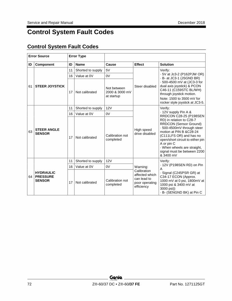
Service and Repair Manual December 2018
Control System Fault Codes
72 Z®-60/37 DC • Z®-60/37 FE Part No. 1271125GT
Control System Fault Codes Error Source Error Type
ID Component ID Name Cause Effect Solution
61 STEER JOYSTICK
11 Shorted to supply 5V
Steer disabled
Verify: · 5V at Jc3-2 (P162PJW OR) · B- at JC3-1 (JSGND BR) · 500-4500 mV at (JC3-3 for dual axis joystick) & PCON C46-11 (C159STC BL/WH) through joystick motion. Note: 1500 to 3500 mV for rocker style joystick at JC3-5.
16 Value at 0V 0V
17 Not calibrated Not between 2000 & 3000 mV at startup
63 STEER ANGLE SENSOR
11 Shorted to supply 12V
High speed drive disabled
Verify: · 12V supply Pin A & RRDCON C28-25 (P198SEN RD) in relation to C28-7 RRDCON (Sensor Ground) · 500-4500mV through steer motion at PIN B &C28-24 (C111LFS OR) and has no open/short circuit to either pin A or pin C · When wheels are straight, signal must be between 2200 & 3400 mV
16 Value at 0V 0V
17 Not calibrated Calibration not completed
64 HYDRAULIC PRESSURE SENSOR
11 Shorted to supply 12V
Warning: Calibration affected which can lead to poor operating efficiency
Verify: · 12V (P198SEN RD) on Pin A · Signal (C245PSR GR) at C34-17 ECON (Approx. 1000 mV at 0 psi, 1800mV at 1000 psi & 3400 mV at 3000 psi)) · B- (SENGND BK) at Pin C
16 Value at 0V 0V
17 Not calibrated Calibration not completed
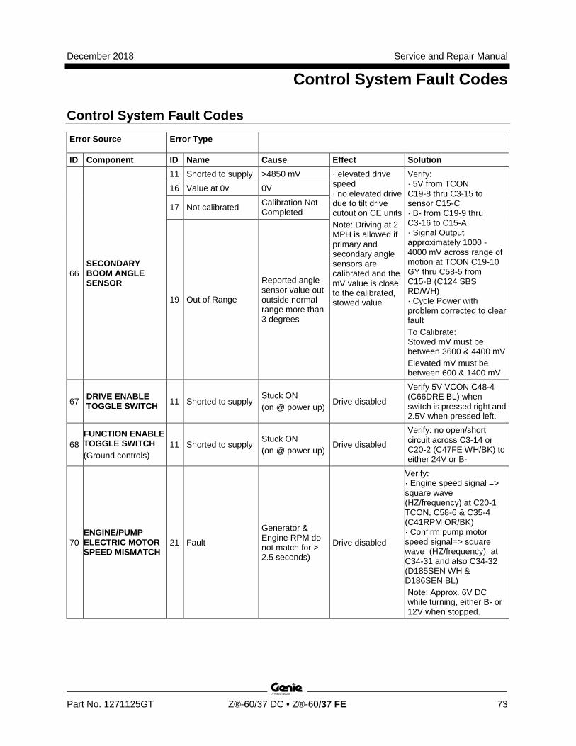
December 2018 Service and Repair Manual
Control System Fault Codes
Part No. 1271125GT Z®-60/37 DC • Z®-60/37 FE 73
Control System Fault Codes Error Source Error Type
ID Component ID Name Cause Effect Solution
66 SECONDARY BOOM ANGLE SENSOR
11 Shorted to supply >4850 mV · elevated drive speed · no elevated drive due to tilt drive cutout on CE units Note: Driving at 2 MPH is allowed if primary and secondary angle sensors are calibrated and the mV value is close to the calibrated, stowed value
Verify: · 5V from TCON C19-8 thru C3-15 to sensor C15-C · B- from C19-9 thru C3-16 to C15-A · Signal Output approximately 1000 - 4000 mV across range of motion at TCON C19-10 GY thru C58-5 from C15-B (C124 SBS RD/WH) · Cycle Power with problem corrected to clear fault To Calibrate: Stowed mV must be between 3600 & 4400 mV Elevated mV must be between 600 & 1400 mV
16 Value at 0v 0V
17 Not calibrated Calibration Not Completed
19 Out of Range
Reported angle sensor value out outside normal range more than 3 degrees
67 DRIVE ENABLE TOGGLE SWITCH 11 Shorted to supply
Stuck ON (on @ power up)
Drive disabled
Verify 5V VCON C48-4 (C66DRE BL) when switch is pressed right and 2.5V when pressed left.
68 FUNCTION ENABLE TOGGLE SWITCH (Ground controls)
11 Shorted to supply Stuck ON (on @ power up)
Drive disabled
Verify: no open/short circuit across C3-14 or C20-2 (C47FE WH/BK) to either 24V or B-
70 ENGINE/PUMP ELECTRIC MOTOR SPEED MISMATCH
21 Fault
Generator & Engine RPM do not match for > 2.5 seconds)
Drive disabled
Verify: · Engine speed signal => square wave (HZ/frequency) at C20-1 TCON, C58-6 & C35-4 (C41RPM OR/BK) · Confirm pump motor speed signal=> square wave (HZ/frequency) at C34-31 and also C34-32 (D185SEN WH & D186SEN BL) Note: Approx. 6V DC while turning, either B- or 12V when stopped.
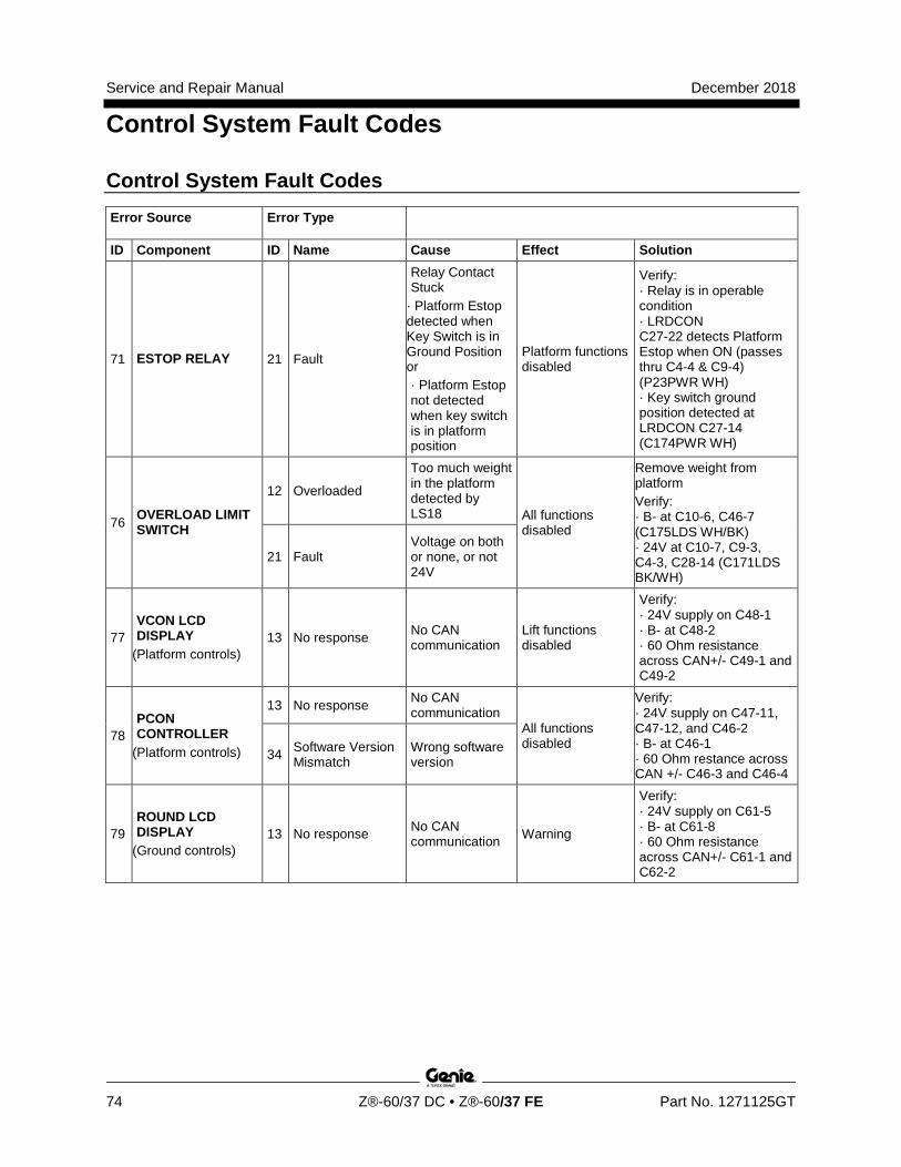
Service and Repair Manual December 2018
Control System Fault Codes
74 Z®-60/37 DC • Z®-60/37 FE Part No. 1271125GT
Control System Fault Codes Error Source Error Type
ID Component ID Name Cause Effect Solution
71 ESTOP RELAY 21 Fault
Relay Contact Stuck
· Platform Estop detected when Key Switch is in Ground Position or · Platform Estop not detected when key switch is in platform position
Platform functions disabled
Verify: · Relay is in operable condition · LRDCON C27-22 detects Platform Estop when ON (passes thru C4-4 & C9-4) (P23PWR WH) · Key switch ground position detected at LRDCON C27-14 (C174PWR WH)
76 OVERLOAD LIMIT SWITCH
12 Overloaded
Too much weight in the platform detected by LS18 All functions
disabled
Remove weight from platform Verify: · B- at C10-6, C46-7 (C175LDS WH/BK) · 24V at C10-7, C9-3, C4-3, C28-14 (C171LDS BK/WH)
21 Fault Voltage on both or none, or not 24V
77 VCON LCD DISPLAY
(Platform controls) 13 No response No CAN
communication Lift functions disabled
Verify: · 24V supply on C48-1 · B- at C48-2 · 60 Ohm resistance across CAN+/- C49-1 and C49-2
78 PCON CONTROLLER
(Platform controls)
13 No response No CAN communication
All functions disabled
Verify: · 24V supply on C47-11, C47-12, and C46-2 · B- at C46-1 · 60 Ohm restance across CAN +/- C46-3 and C46-4
34 Software Version Mismatch
Wrong software version
79 ROUND LCD DISPLAY
(Ground controls) 13 No response No CAN
communication Warning
Verify: · 24V supply on C61-5 · B- at C61-8 · 60 Ohm resistance across CAN+/- C61-1 and C62-2
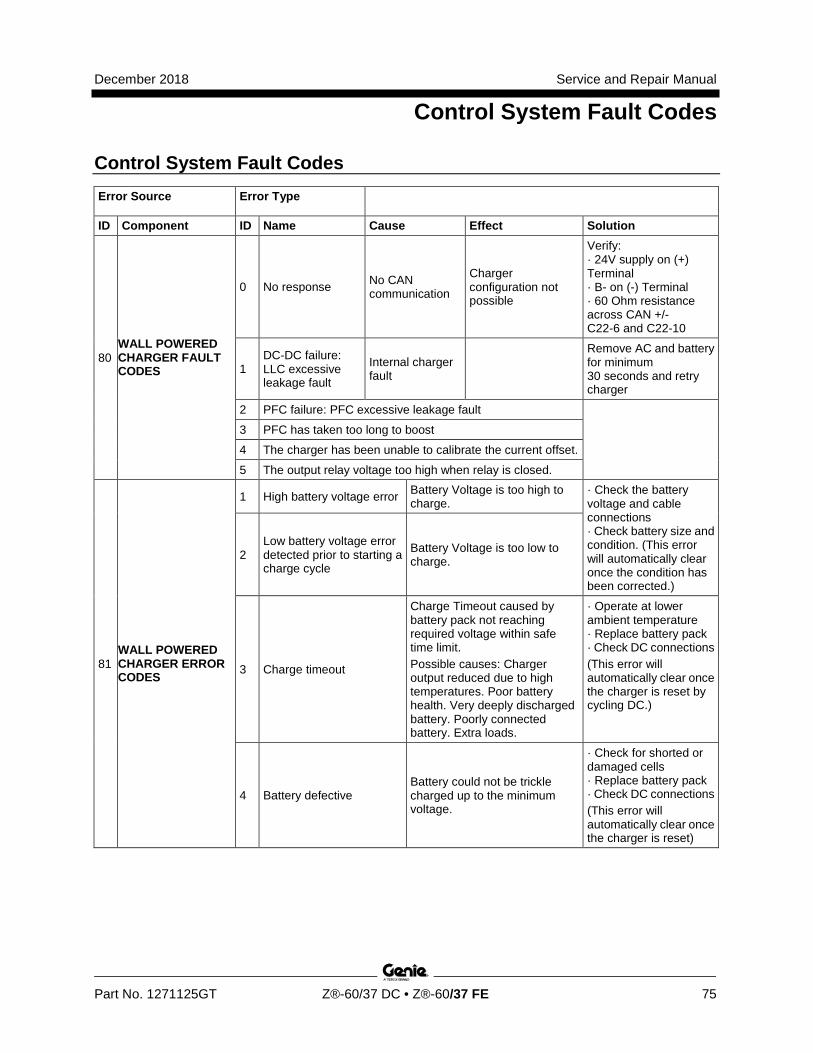
December 2018 Service and Repair Manual
Control System Fault Codes
Part No. 1271125GT Z®-60/37 DC • Z®-60/37 FE 75
Control System Fault Codes Error Source Error Type
ID Component ID Name Cause Effect Solution
80 WALL POWERED CHARGER FAULT CODES
0 No response No CAN communication
Charger configuration not possible
Verify: · 24V supply on (+) Terminal · B- on (-) Terminal · 60 Ohm resistance across CAN +/- C22-6 and C22-10
1 DC-DC failure: LLC excessive leakage fault
Internal charger fault
Remove AC and battery for minimum 30 seconds and retry charger
2 PFC failure: PFC excessive leakage fault
3 PFC has taken too long to boost
4 The charger has been unable to calibrate the current offset.
5 The output relay voltage too high when relay is closed.
81 WALL POWERED CHARGER ERROR CODES
1 High battery voltage error Battery Voltage is too high to charge.
· Check the battery voltage and cable connections · Check battery size and condition. (This error will automatically clear once the condition has been corrected.)
2 Low battery voltage error detected prior to starting a charge cycle
Battery Voltage is too low to charge.
3 Charge timeout
Charge Timeout caused by battery pack not reaching required voltage within safe time limit. Possible causes: Charger output reduced due to high temperatures. Poor battery health. Very deeply discharged battery. Poorly connected battery. Extra loads.
· Operate at lower ambient temperature · Replace battery pack · Check DC connections (This error will automatically clear once the charger is reset by cycling DC.)
4 Battery defective Battery could not be trickle charged up to the minimum voltage.
· Check for shorted or damaged cells · Replace battery pack · Check DC connections (This error will automatically clear once the charger is reset)
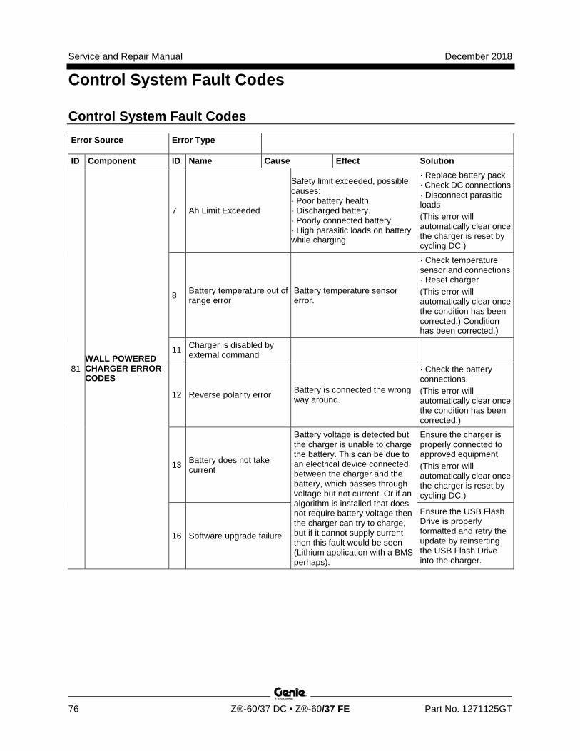
Service and Repair Manual December 2018
Control System Fault Codes
76 Z®-60/37 DC • Z®-60/37 FE Part No. 1271125GT
Control System Fault Codes Error Source Error Type
ID Component ID Name Cause Effect Solution
81 WALL POWERED CHARGER ERROR CODES
7 Ah Limit Exceeded
Safety limit exceeded, possible causes: · Poor battery health. · Discharged battery. · Poorly connected battery. · High parasitic loads on battery while charging.
· Replace battery pack · Check DC connections · Disconnect parasitic loads (This error will automatically clear once the charger is reset by cycling DC.)
8 Battery temperature out of range error
Battery temperature sensor error.
· Check temperature sensor and connections · Reset charger (This error will automatically clear once the condition has been corrected.) Condition has been corrected.)
11 Charger is disabled by external command
12 Reverse polarity error Battery is connected the wrong way around.
· Check the battery connections. (This error will automatically clear once the condition has been corrected.)
13 Battery does not take current
Battery voltage is detected but the charger is unable to charge the battery. This can be due to an electrical device connected between the charger and the battery, which passes through voltage but not current. Or if an algorithm is installed that does not require battery voltage then the charger can try to charge, but if it cannot supply current then this fault would be seen (Lithium application with a BMS perhaps).
Ensure the charger is properly connected to approved equipment (This error will automatically clear once the charger is reset by cycling DC.)
16 Software upgrade failure
Ensure the USB Flash Drive is properly formatted and retry the update by reinserting the USB Flash Drive into the charger.
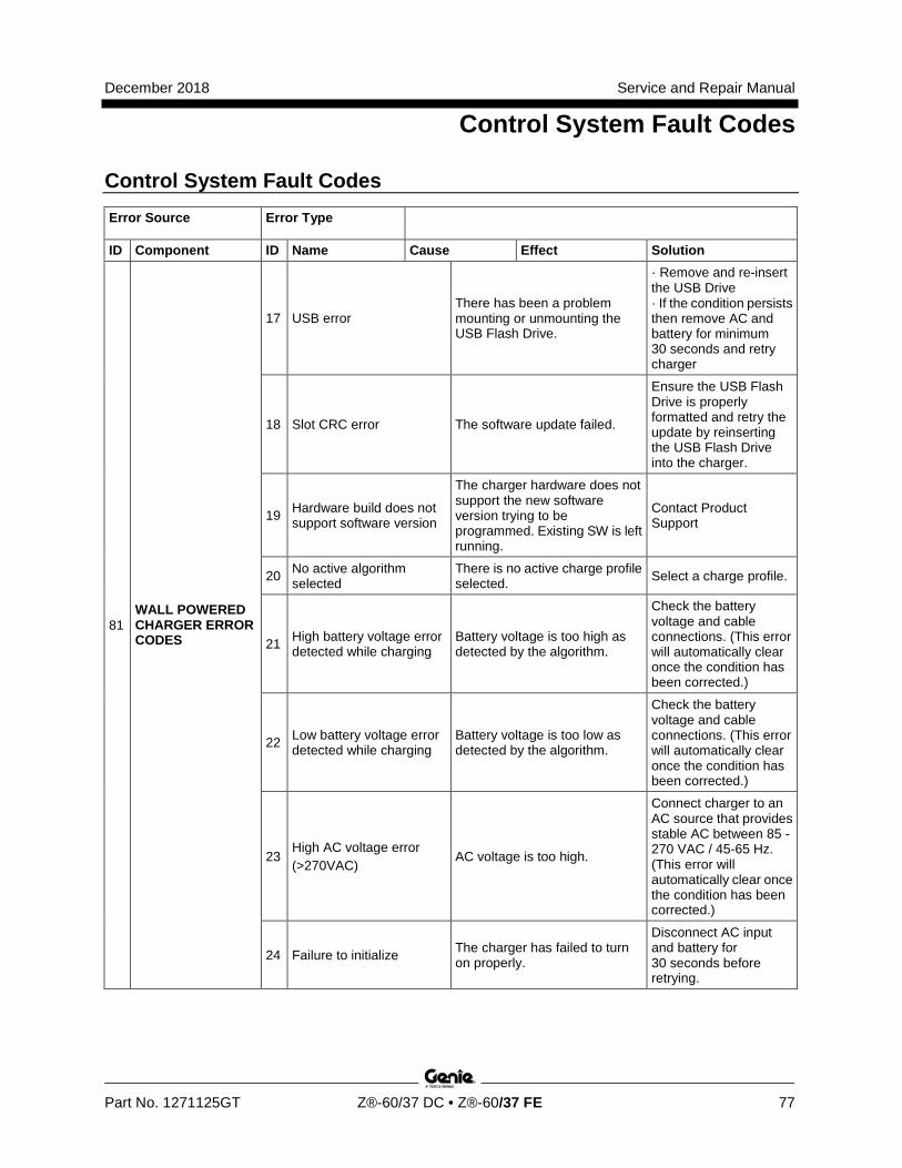
December 2018 Service and Repair Manual
Control System Fault Codes
Part No. 1271125GT Z®-60/37 DC • Z®-60/37 FE 77
Control System Fault Codes Error Source Error Type
ID Component ID Name Cause Effect Solution
81 WALL POWERED CHARGER ERROR CODES
17 USB error There has been a problem mounting or unmounting the USB Flash Drive.
· Remove and re-insert the USB Drive · If the condition persists then remove AC and battery for minimum 30 seconds and retry charger
18 Slot CRC error The software update failed.
Ensure the USB Flash Drive is properly formatted and retry the update by reinserting the USB Flash Drive into the charger.
19 Hardware build does not support software version
The charger hardware does not support the new software version trying to be programmed. Existing SW is left running.
Contact Product Support
20 No active algorithm selected
There is no active charge profile selected. Select a charge profile.
21 High battery voltage error detected while charging
Battery voltage is too high as detected by the algorithm.
Check the battery voltage and cable connections. (This error will automatically clear once the condition has been corrected.)
22 Low battery voltage error detected while charging
Battery voltage is too low as detected by the algorithm.
Check the battery voltage and cable connections. (This error will automatically clear once the condition has been corrected.)
23 High AC voltage error (>270VAC)
AC voltage is too high.
Connect charger to an AC source that provides stable AC between 85 - 270 VAC / 45-65 Hz. (This error will automatically clear once the condition has been corrected.)
24 Failure to initialize The charger has failed to turn on properly.
Disconnect AC input and battery for 30 seconds before retrying.
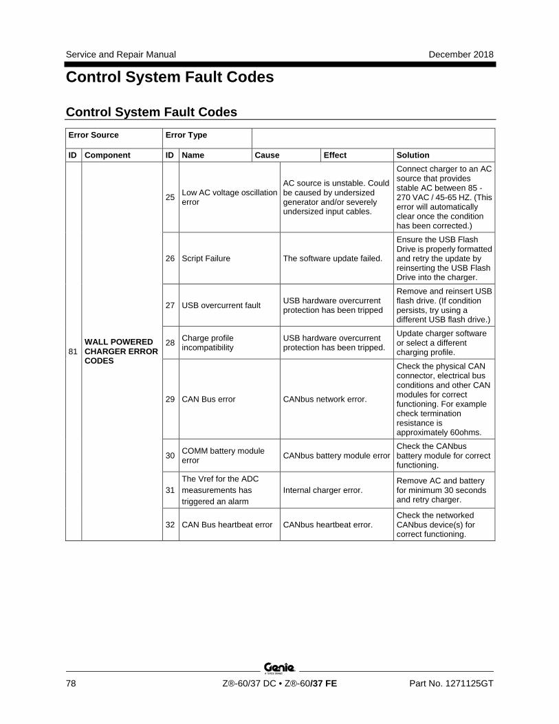
Service and Repair Manual December 2018
Control System Fault Codes
78 Z®-60/37 DC • Z®-60/37 FE Part No. 1271125GT
Control System Fault Codes Error Source Error Type
ID Component ID Name Cause Effect Solution
81 WALL POWERED CHARGER ERROR CODES
25 Low AC voltage oscillation error
AC source is unstable. Could be caused by undersized generator and/or severely undersized input cables.
Connect charger to an AC source that provides stable AC between 85 - 270 VAC / 45-65 HZ. (This error will automatically clear once the condition has been corrected.)
26 Script Failure The software update failed.
Ensure the USB Flash Drive is properly formatted and retry the update by reinserting the USB Flash Drive into the charger.
27 USB overcurrent fault USB hardware overcurrent protection has been tripped
Remove and reinsert USB flash drive. (If condition persists, try using a different USB flash drive.)
28 Charge profile incompatibility
USB hardware overcurrent protection has been tripped.
Update charger software or select a different charging profile.
29 CAN Bus error CANbus network error.
Check the physical CAN connector, electrical bus conditions and other CAN modules for correct functioning. For example check termination resistance is approximately 60ohms.
30 COMM battery module error CANbus battery module error
Check the CANbus battery module for correct functioning.
31 The Vref for the ADC measurements has triggered an alarm
Internal charger error. Remove AC and battery for minimum 30 seconds and retry charger.
32 CAN Bus heartbeat error CANbus heartbeat error. Check the networked CANbus device(s) for correct functioning.
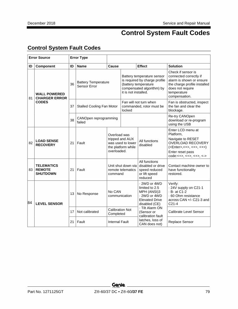
December 2018 Service and Repair Manual
Control System Fault Codes
Part No. 1271125GT Z®-60/37 DC • Z®-60/37 FE 79
Control System Fault Codes Error Source Error Type
ID Component ID Name Cause Effect Solution
81 WALL POWERED CHARGER ERROR CODES
36 Battery Temperature Sensor Error
Battery temperature sensor is required by charge profile (battery temperature compensated algorithm) by it is not installed.
Check if sensor is connected correctly if alarm is shown or ensure the charge profile installed does not require temperature compensation.
37 Stalled Cooling Fan Motor Fan will not turn when commanded, rotor must be locked
Fan is obstructed, inspect the fan and clear the blockage.
38 CANOpen reprogramming failed
Re-try CANOpen download or re-program using the USB
82 LOAD SENSE RECOVERY 21 Fault
Overload was tripped and AUX was used to lower the platform while overloaded.
All functions disabled
Enter LCD menu at Platform, Navigate to RESET OVERLOAD RECOVERY (<Enter>,<+>, <+>, <+>) Enter reset pass code:<+>, <+>, <+>, <->
83 TELEMATICS REMOTE SHUTDOWN
21 Fault Unit shut down via remote telematics command
All functions disabled or drive speed reduced or lift speed reduced
Contact machine owner to have functionality restored.
84 LEVEL SENSOR
13 No Response No CAN communication
· 2WD or 4WD limited to 2.5 MPH (ANSI)3 · 2WD or 4WD Elevated Drive disabled (CE) · Tilt Alarm ON (Sensor or calibration fault latches, loss of CAN does not)
Verify: · 24V supply on C21-1 · B- at C1-2 · 60 Ohm resistance across CAN +/- C21-3 and C21-4
17 Not calibrated Calibration Not Completed Calibrate Level Sensor
21 Fault Internal Fault Replace Sensor
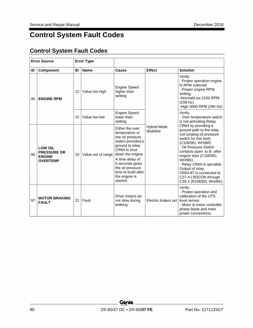
Service and Repair Manual December 2018
Control System Fault Codes
80 Z®-60/37 DC • Z®-60/37 FE Part No. 1271125GT
Control System Fault Codes Error Source Error Type
ID Component ID Name Cause Effect Solution
95 ENGINE RPM
12 Value too high Engine Speed higher than setting
Hybrid Mode disabled
Verify: · Proper operation engine hi RPM solenoid · Proper engine RPM setting: -Normal/Low 2150 RPM (208 Hz) -High 3000 RPM (290 Hz)
15 Value too low Engine Speed lower than setting
Verify: · Over temperature switch is not activating Relay CR64 by providing a ground path to the relay coil {unplug oil pressure switch for this test} (C108SEL WH/BK) · Oil Pressure Switch contacts open to B- after engine start (C108SEL WH/BK) · Relay CR64 is operable. Output of relay CR64-87 is connected to C27-4 LRDCON through C35-1 (R108SEL WH/BK)
96
LOW OIL PRESSURE OR ENGINE OVERTEMP
19 Value out of range
Either the over temperature or low oil pressure switch provided a ground to relay CR64 to shut down the engine. A time delay of 5 seconds gives the oil pressure time to build after the engine is started.
97 MOTOR BRAKING FAULT 21 Fault
Drive motors do not slow during braking
Electric brakes set
Verify: · Proper operation and calibration of the UTS level sensor · Motor & motor controller phase leads and main power connections.
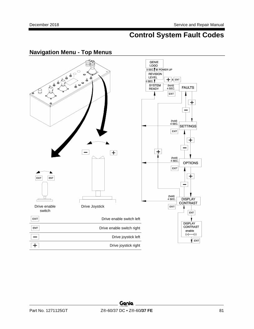
December 2018 Service and Repair Manual
Control System Fault Codes
Part No. 1271125GT Z®-60/37 DC • Z®-60/37 FE 81
Section 5 Navigati on Menus
Navigation Menu - Top Menus
Drive enable switch
Drive Joystick
Drive enable switch left
Drive enable switch right
Drive joystick left
Drive joystick right
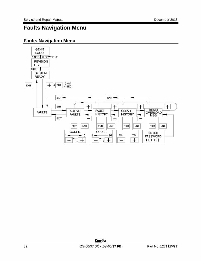
Service and Repair Manual December 2018
Faults Navigation Menu
82 Z®-60/37 DC • Z®-60/37 FE Part No. 1271125GT
Faults Navigation Menu
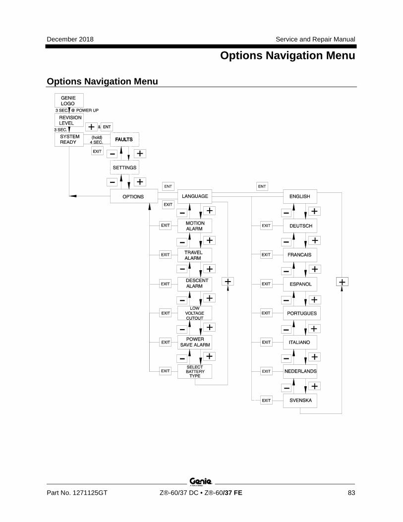
December 2018 Service and Repair Manual
Options Navigation Menu
Part No. 1271125GT Z®-60/37 DC • Z®-60/37 FE 83
Options Navigation Menu
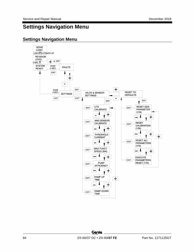
Service and Repair Manual December 2018
Settings Navigation Menu
84 Z®-60/37 DC • Z®-60/37 FE Part No. 1271125GT
Settings Navigation Menu
December 2018 Service and Repair Manual
Schematics
Part No. 1271125GT Z®-60/37 DC • Z®-60/37 FE 85
Section 6 Schematics
Observe and Obey: R Troubleshooting and repair procedures shall be
completed by a person trained and qualified on the repair of this machine
R Immediately tag and remove from service a damaged or malfunctioning machine.
R Repair any machine damage or malfunction before operating the machine.
Before Troubleshooting: R Read, understand and obey the safety rules
and operating instructions in the appropriate operator's manual on your machine.
R Be sure that all necessary tools and test equipment are available and ready for use.
About This Section There are two groups of schematics in this section.
Electrical Schematics
Electrocution/burn hazard. Contact with electrically charged circuits could result in death or serious injury. Remove all rings, watches and other jewelry.
Hydraulic Schematics
Bodily injury hazard. Spraying hydraulic oil can penetrate and burn skin. Loosen hydraulic connections very slowly to allow the oil pressure to dissipate gradually. Do not allow oil to squirt or spray.
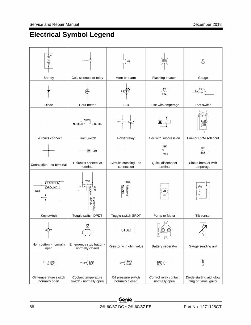
Service and Repair Manual December 2018
Electrical Symbol Legend
86 Z®-60/37 DC • Z®-60/37 FE Part No. 1271125GT
Battery Coil, solenoid or relay Horn or alarm Flashing beacon Gauge
Diode Hour meter LED Fuse with amperage Foot switch
T-circuits connect Limit Switch Power relay Coil with suppression Fuel or RPM solenoid
Connection - no terminal T-circuits connect at terminal
Circuits crossing - no connection
Quick disconnect terminal
Circuit breaker with amperage
Key switch Toggle switch DPDT Toggle switch SPDT Pump or Motor Tilt sensor
Horn button - normally open
Emergency stop button - normally closed Resistor with ohm value Battery seperator Gauge sending unit
Oil temperature switch normally open
Coolant temperature switch - normally open
Oil pressure switch normally closed
Control relay contact normally open
Diode starting aid, glow plug or flame ignitor
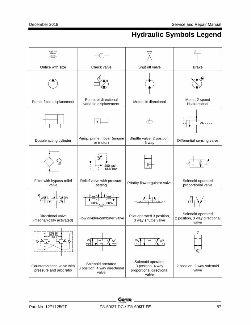
December 2018 Service and Repair Manual
Hydraulic Symbols Legend
Part No. 1271125GT Z®-60/37 DC • Z®-60/37 FE 87
Orifice with size Check valve Shut off valve Brake
Pump, fixed displacement Pump, bi-directional variable displacement Motor, bi-directional Motor, 2 speed
bi-directional
Double acting cylinder Pump, prime mover (engine or motor)
Shuttle valve. 2 position, 3 way Differential sensing valve
Filter with bypass relief valve
Relief valve with pressure setting Priority flow regulator valve Solenoid operated
proportional valve
Directional valve (mechanically activated) Flow divider/combiner valve Pilot operated 3 position,
3 way shuttle valve
Solenoid operated 2 position, 3 way directional
valve
Counterbalance valve with pressure and pilot ratio
Solenoid operated 3 position, 4 way directional
valve
Solenoid operated 3 position, 4 way
proportional directional valve
2 position, 2 way solenoid valve
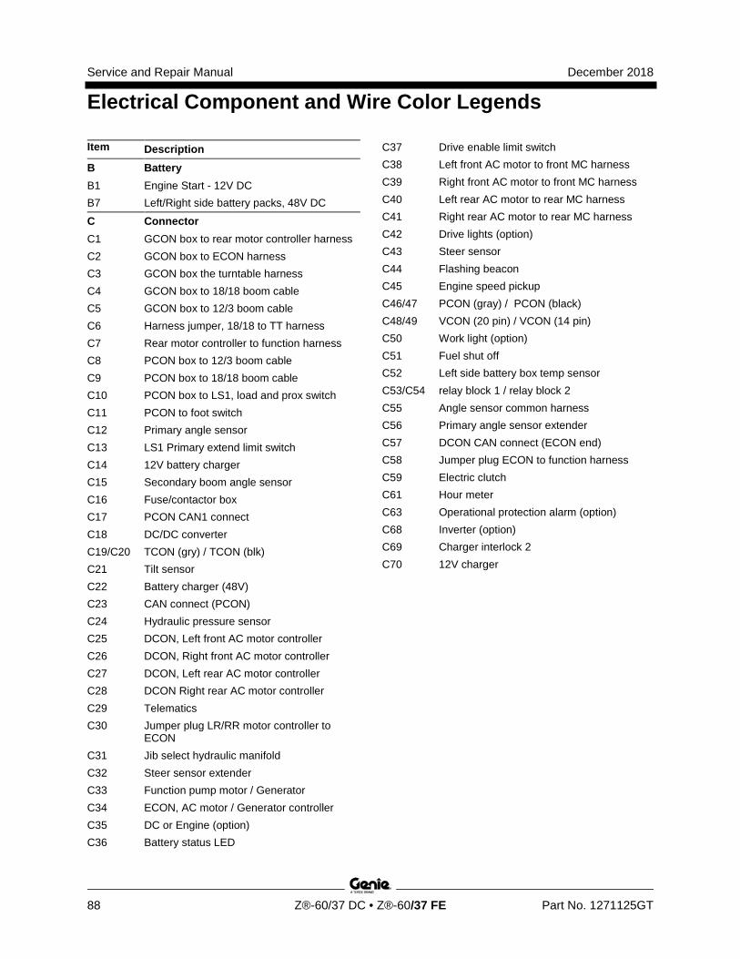
Service and Repair Manual December 2018
Electrical Component and Wire Color Legends
88 Z®-60/37 DC • Z®-60/37 FE Part No. 1271125GT
Item Description B Battery B1 Engine Start - 12V DC B7 Left/Right side battery packs, 48V DC
C Connector C1 GCON box to rear motor controller harness C2 GCON box to ECON harness C3 GCON box the turntable harness C4 GCON box to 18/18 boom cable C5 GCON box to 12/3 boom cable C6 Harness jumper, 18/18 to TT harness C7 Rear motor controller to function harness C8 PCON box to 12/3 boom cable C9 PCON box to 18/18 boom cable C10 PCON box to LS1, load and prox switch C11 PCON to foot switch C12 Primary angle sensor C13 LS1 Primary extend limit switch C14 12V battery charger C15 Secondary boom angle sensor C16 Fuse/contactor box C17 PCON CAN1 connect C18 DC/DC converter C19/C20 TCON (gry) / TCON (blk) C21 Tilt sensor C22 Battery charger (48V) C23 CAN connect (PCON) C24 Hydraulic pressure sensor C25 DCON, Left front AC motor controller C26 DCON, Right front AC motor controller C27 DCON, Left rear AC motor controller C28 DCON Right rear AC motor controller C29 Telematics C30 Jumper plug LR/RR motor controller to
ECON C31 Jib select hydraulic manifold C32 Steer sensor extender C33 Function pump motor / Generator C34 ECON, AC motor / Generator controller C35 DC or Engine (option) C36 Battery status LED
C37 Drive enable limit switch C38 Left front AC motor to front MC harness C39 Right front AC motor to front MC harness C40 Left rear AC motor to rear MC harness C41 Right rear AC motor to rear MC harness C42 Drive lights (option) C43 Steer sensor C44 Flashing beacon C45 Engine speed pickup C46/47 PCON (gray) / PCON (black) C48/49 VCON (20 pin) / VCON (14 pin) C50 Work light (option) C51 Fuel shut off C52 Left side battery box temp sensor C53/C54 relay block 1 / relay block 2 C55 Angle sensor common harness C56 Primary angle sensor extender C57 DCON CAN connect (ECON end) C58 Jumper plug ECON to function harness C59 Electric clutch C61 Hour meter C63 Operational protection alarm (option) C68 Inverter (option) C69 Charger interlock 2 C70 12V charger
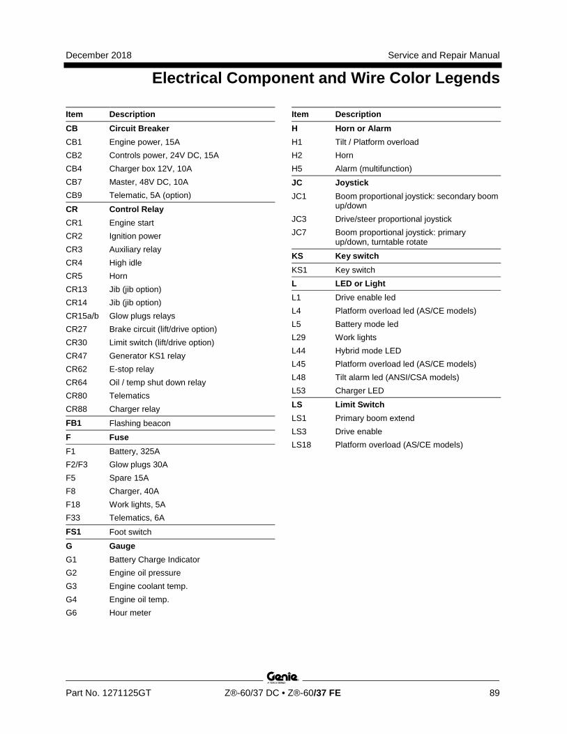
December 2018 Service and Repair Manual
Electrical Component and Wire Color Legends
Part No. 1271125GT Z®-60/37 DC • Z®-60/37 FE 89
Item Description CB Circuit Breaker CB1 Engine power, 15A CB2 Controls power, 24V DC, 15A CB4 Charger box 12V, 10A CB7 Master, 48V DC, 10A CB9 Telematic, 5A (option)
CR Control Relay CR1 Engine start CR2 Ignition power CR3 Auxiliary relay CR4 High idle CR5 Horn CR13 Jib (jib option) CR14 Jib (jib option) CR15a/b Glow plugs relays CR27 Brake circuit (lift/drive option) CR30 Limit switch (lift/drive option) CR47 Generator KS1 relay CR62 E-stop relay CR64 Oil / temp shut down relay CR80 Telematics CR88 Charger relay
FB1 Flashing beacon
F Fuse
F1 Battery, 325A F2/F3 Glow plugs 30A F5 Spare 15A F8 Charger, 40A F18 Work lights, 5A F33 Telematics, 6A
FS1 Foot switch
G Gauge G1 Battery Charge Indicator G2 Engine oil pressure G3 Engine coolant temp. G4 Engine oil temp. G6 Hour meter
Item Description H Horn or Alarm H1 Tilt / Platform overload H2 Horn H5 Alarm (multifunction)
JC Joystick JC1 Boom proportional joystick: secondary boom
up/down JC3 Drive/steer proportional joystick JC7 Boom proportional joystick: primary
up/down, turntable rotate
KS Key switch KS1 Key switch L LED or Light L1 Drive enable led L4 Platform overload led (AS/CE models) L5 Battery mode led L29 Work lights L44 Hybrid mode LED L45 Platform overload led (AS/CE models) L48 Tilt alarm led (ANSI/CSA models) L53 Charger LED
LS Limit Switch LS1 Primary boom extend LS3 Drive enable LS18 Platform overload (AS/CE models)
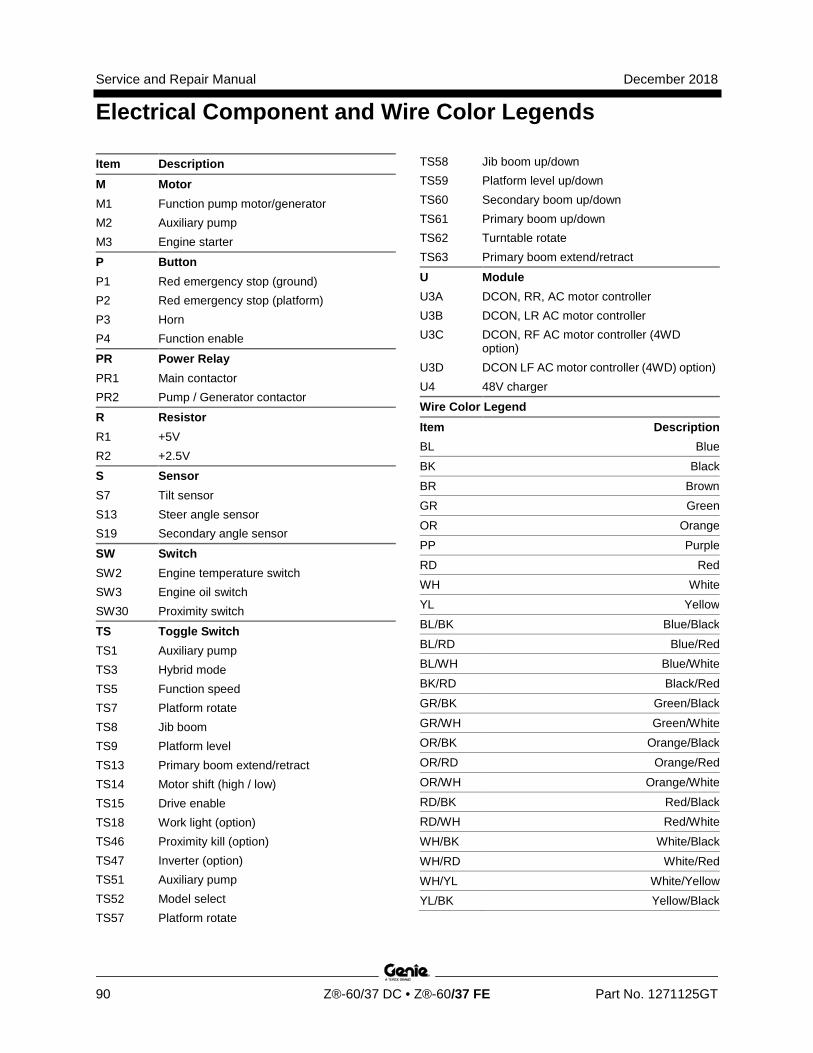
Service and Repair Manual December 2018
Electrical Component and Wire Color Legends
90 Z®-60/37 DC • Z®-60/37 FE Part No. 1271125GT
Item Description M Motor M1 Function pump motor/generator M2 Auxiliary pump M3 Engine starter
P Button P1 Red emergency stop (ground) P2 Red emergency stop (platform) P3 Horn P4 Function enable
PR Power Relay PR1 Main contactor PR2 Pump / Generator contactor
R Resistor R1 +5V R2 +2.5V
S Sensor S7 Tilt sensor S13 Steer angle sensor S19 Secondary angle sensor
SW Switch SW2 Engine temperature switch SW3 Engine oil switch SW30 Proximity switch
TS Toggle Switch TS1 Auxiliary pump TS3 Hybrid mode TS5 Function speed TS7 Platform rotate TS8 Jib boom TS9 Platform level TS13 Primary boom extend/retract TS14 Motor shift (high / low) TS15 Drive enable TS18 Work light (option) TS46 Proximity kill (option) TS47 Inverter (option) TS51 Auxiliary pump TS52 Model select TS57 Platform rotate
TS58 Jib boom up/down TS59 Platform level up/down TS60 Secondary boom up/down TS61 Primary boom up/down TS62 Turntable rotate TS63 Primary boom extend/retract
U Module U3A DCON, RR, AC motor controller U3B DCON, LR AC motor controller U3C DCON, RF AC motor controller (4WD
option) U3D DCON LF AC motor controller (4WD) option) U4 48V charger
Wire Color Legend Item Description BL Blue BK Black BR Brown GR Green OR Orange PP Purple RD Red WH White YL Yellow BL/BK Blue/Black BL/RD Blue/Red BL/WH Blue/White BK/RD Black/Red GR/BK Green/Black GR/WH Green/White OR/BK Orange/Black OR/RD Orange/Red OR/WH Orange/White RD/BK Red/Black RD/WH Red/White WH/BK White/Black WH/RD White/Red WH/YL White/Yellow YL/BK Yellow/Black
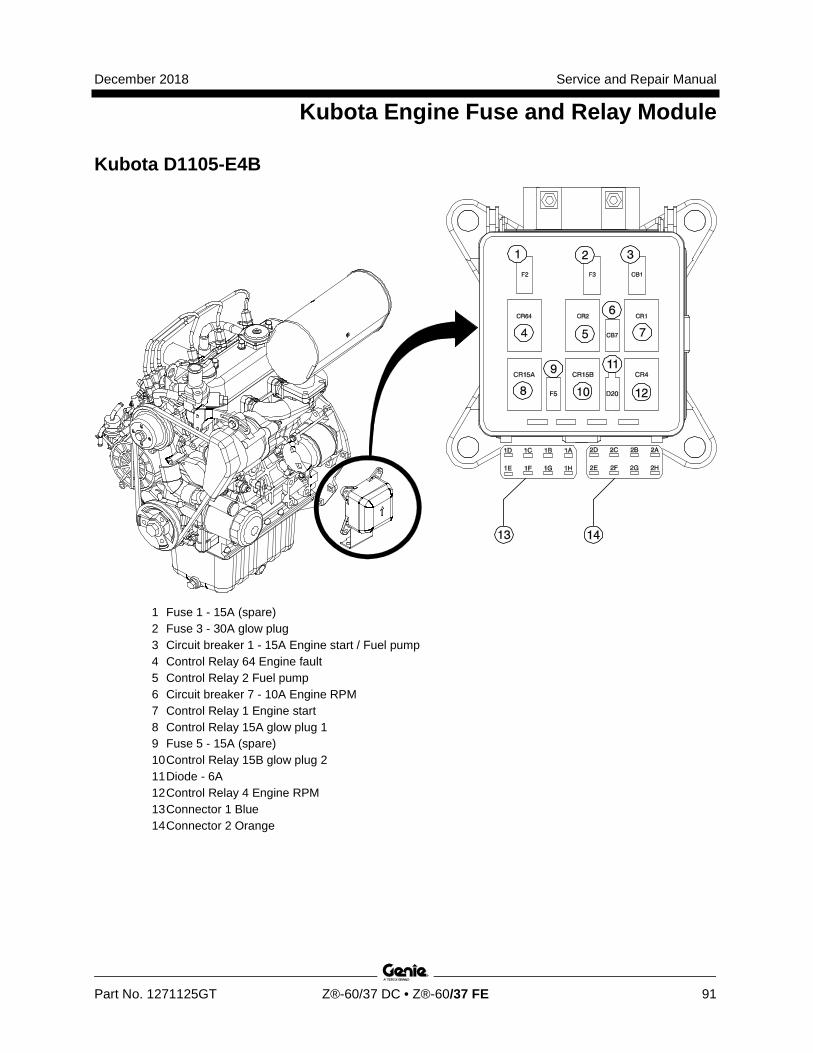
December 2018 Service and Repair Manual
Kubota Engine Fuse and Relay Module
Part No. 1271125GT Z®-60/37 DC • Z®-60/37 FE 91
Kubota D1105-E4B
1 Fuse 1 - 15A (spare) 2 Fuse 3 - 30A glow plug 3 Circuit breaker 1 - 15A Engine start / Fuel pump 4 Control Relay 64 Engine fault 5 Control Relay 2 Fuel pump 6 Circuit breaker 7 - 10A Engine RPM 7 Control Relay 1 Engine start 8 Control Relay 15A glow plug 1 9 Fuse 5 - 15A (spare) 10 Control Relay 15B glow plug 2 11 Diode - 6A 12 Control Relay 4 Engine RPM 13 Connector 1 Blue 14 Connector 2 Orange
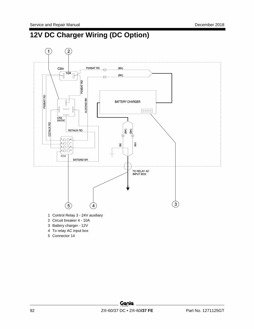
Service and Repair Manual December 2018
12V DC Charger Wiring (DC Option)
92 Z®-60/37 DC • Z®-60/37 FE Part No. 1271125GT
1 Control Relay 3 - 24V auxiliary 2 Circuit breaker 4 - 10A 3 Battery charger - 12V 4 To relay AC input box 5 Connector 14
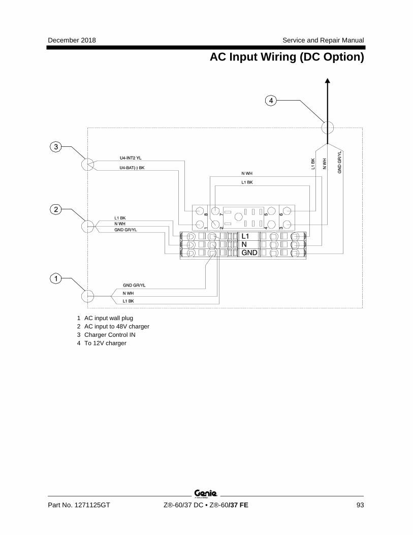
December 2018 Service and Repair Manual
AC Input Wiring (DC Option)
Part No. 1271125GT Z®-60/37 DC • Z®-60/37 FE 93
1 AC input wall plug 2 AC input to 48V charger 3 Charger Control IN 4 To 12V charger
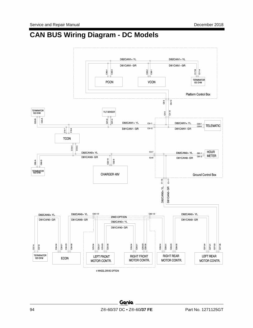
Service and Repair Manual December 2018
CAN BUS Wiring Diagram - DC Models
94 Z®-60/37 DC • Z®-60/37 FE Part No. 1271125GT
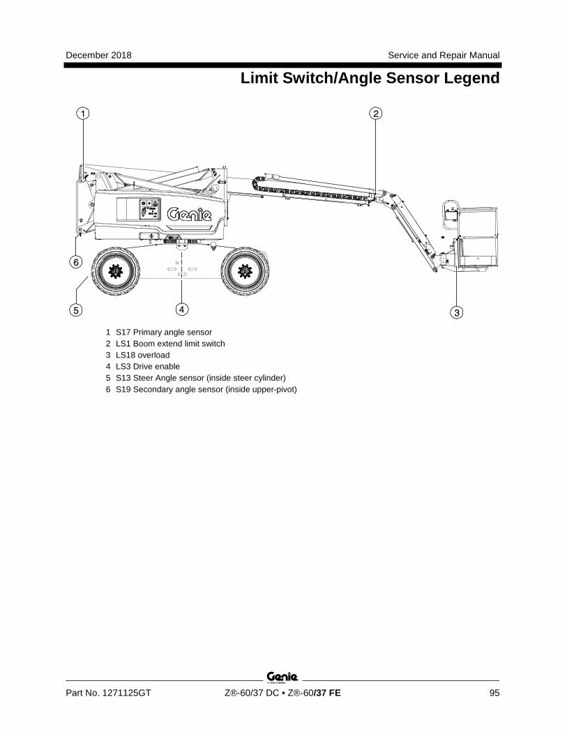
December 2018 Service and Repair Manual
Limit Switch/Angle Sensor Legend
Part No. 1271125GT Z®-60/37 DC • Z®-60/37 FE 95
1 S17 Primary angle sensor 2 LS1 Boom extend limit switch 3 LS18 overload 4 LS3 Drive enable 5 S13 Steer Angle sensor (inside steer cylinder) 6 S19 Secondary angle sensor (inside upper-pivot)

Service and Repair Manual December 2018
96 Z®-60/37 DC • Z®-60/37 FE Part No. 1271125GT
This page intentionally left blank.

December 2018 Service and Repair Manual
97
Wiring Diagram - Options
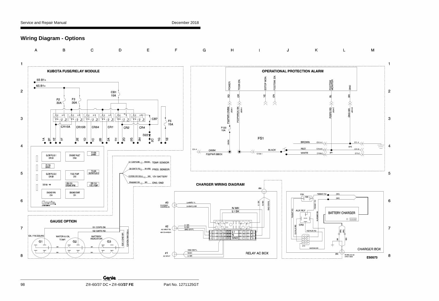
Service and Repair Manual December 2018
98 Z®-60/37 DC • Z®-60/37 FE Part No. 1271125GT
Wiring Diagram - Options
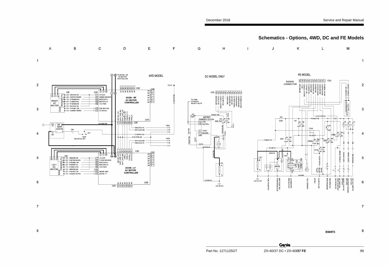
December 2018 Service and Repair Manual
Part No. 1271125GT Z®-60/37 DC • Z®-60/37 FE 99
Schematics - Options, 4WD, DC and FE Models

Service and Repair Manual December 2018
100
Schematics – Options 4WD, DC and FE Models

December 2018 Service and Repair Manual
101
Power Cable Wiring Diagram
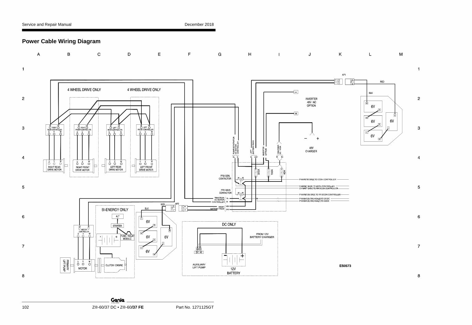
Service and Repair Manual December 2018
102 Z®-60/37 DC • Z®-60/37 FE Part No. 1271125GT
Power Cable Wiring Diagram

December 2018 Service and Repair Manual
103
Hydraulic Schematic, DC and FE Models
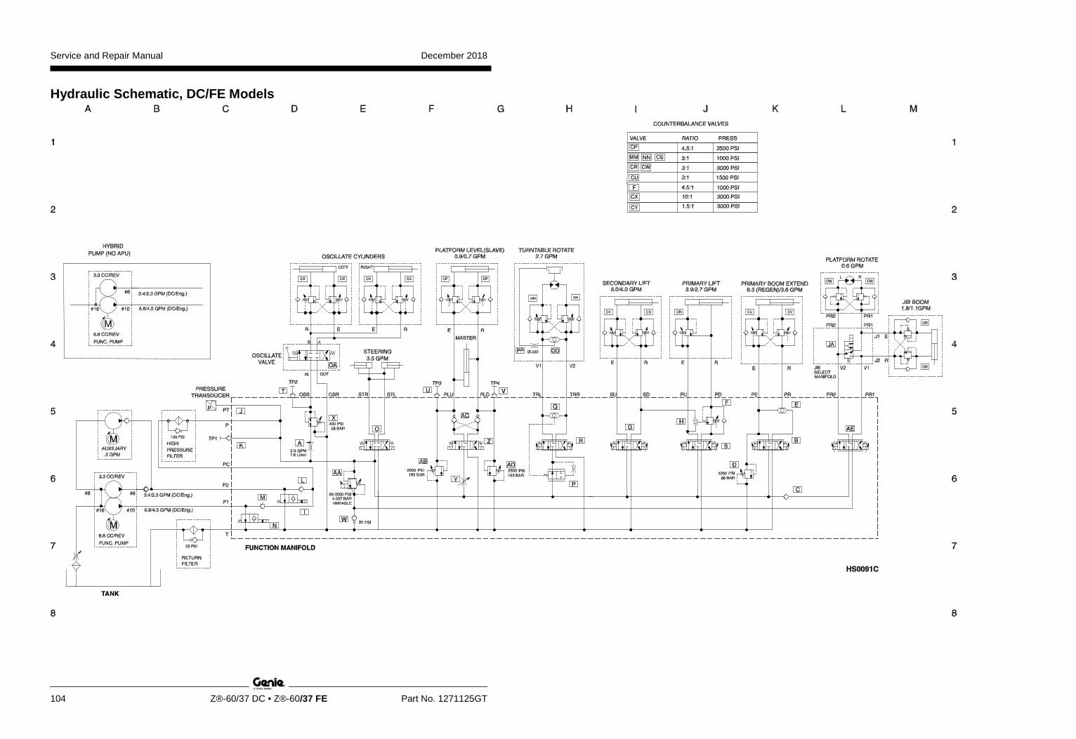
Service and Repair Manual December 2018
104 Z®-60/37 DC • Z®-60/37 FE Part No. 1271125GT
Hydraulic Schematic, DC/FE Models

December 2018 Service and Repair Manual
105
Electrical Schematic, DC/FE Models
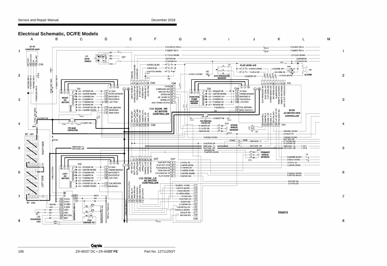
Service and Repair Manual December 2018
106 Z®-60/37 DC • Z®-60/37 FE Part No. 1271125GT
Electrical Schematic, DC/FE Models
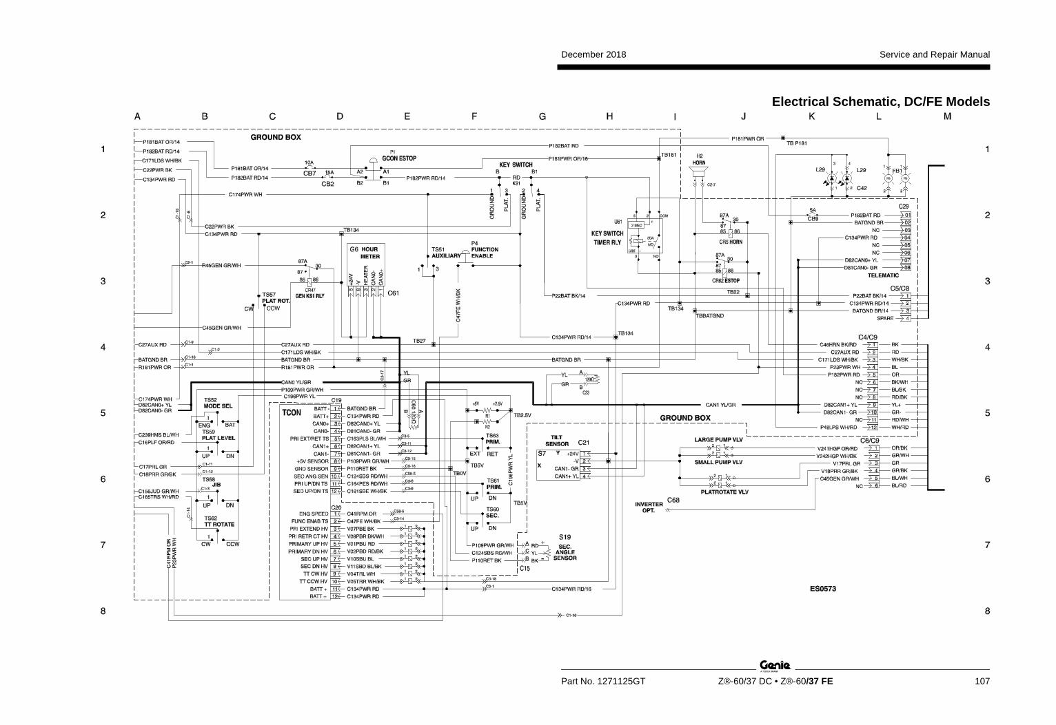
December 2018 Service and Repair Manual
Part No. 1271125GT Z®-60/37 DC • Z®-60/37 FE 107
Electrical Schematic, DC/FE Models
Service and Repair Manual December 2018
108
Electrical Schematic, DC/FE Models
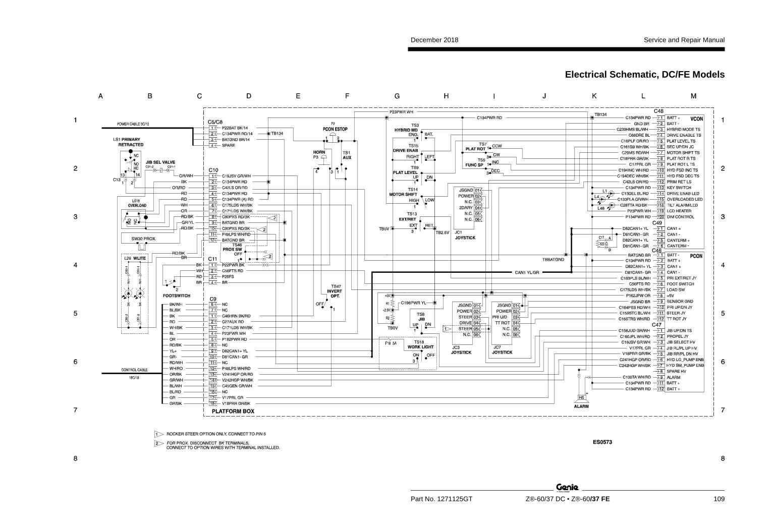
December 2018 Service and Repair Manual
Part No. 1271125GT Z®-60/37 DC • Z®-60/37 FE 109
Electrical Schematic, DC/FE Models

Service and Repair Manual December 2018
110
Electrical Schematic, DC/FE Models

December 2018 Service and Repair Manual
111
Ground Control Box Terminal Strip Wiring Diagram, DC/FE Models
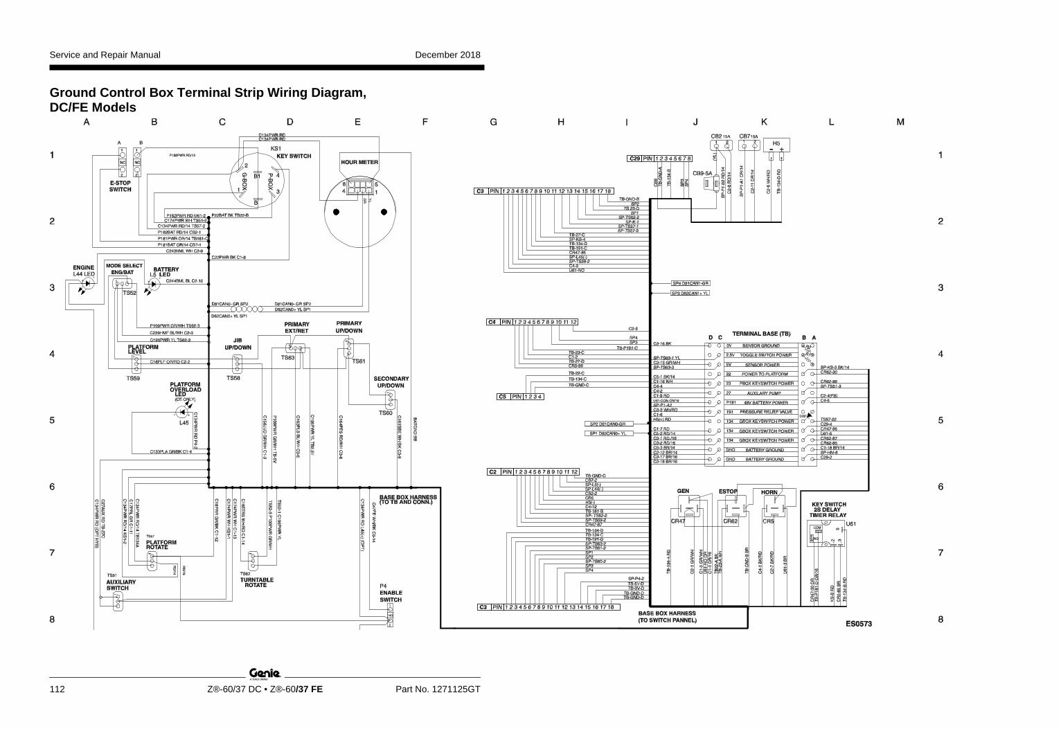
Service and Repair Manual December 2018
112 Z®-60/37 DC • Z®-60/37 FE Part No. 1271125GT
Ground Control Box Terminal Strip Wiring Diagram, DC/FE Models
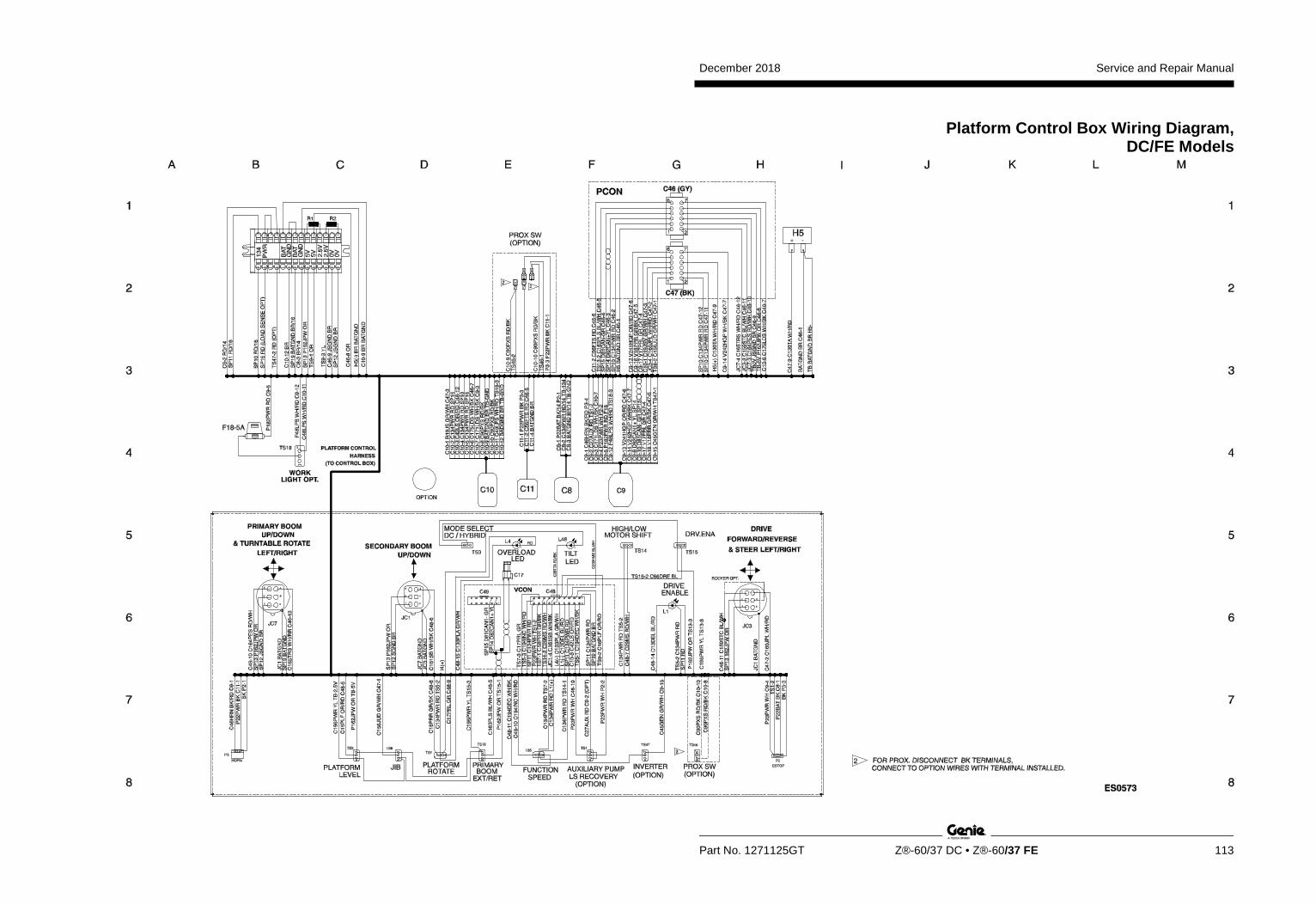
December 2018 Service and Repair Manual
Part No. 1271125GT Z®-60/37 DC • Z®-60/37 FE 113
Platform Control Box Wiring Diagram, DC/FE Models
Service and Repair Manual December 2018
114
Platform Control Box Wiring Diagram, DC/FE Models Z®-60/37 DC • Z®-60/37 FE Part No. 1271125GT Ser vice and R epair M anual
December 2018