Embed Size (px)
Citation preview

Installation, Operation and Maintenance ManualSeries PWSTAWater Softener Systems
IOM-WQ-PWSTA
Table of ContentsJob Specifications Sheet . . . . . . . . . . . . . . . . . . . . . . . . . . . . . . . . . 2General and Commercial Installation Checklist . . . . . . . . . . . . . . . . . 3General and Commercial Installation Checklist . . . . . . . . . . . . . . . . . . 5Regeneration Cycle Program Setting Procedure . . . . . . . . . . . . . . . . 8Time Brine Refill and Meter Setting Procedure . . . . . . . . . . . . . . . . . . 99100 Electro Mechanical Timer Assembly . . . . . . . . . . . . . . . . . . . . 119100 Power Head . . . . . . . . . . . . . . . . . . . . . . . . . . . . . . . . . . . . . . 139100 Control Valve Assembly . . . . . . . . . . . . . . . . . . . . . . . . . . . . . 159000/9100/9500 Second Tank Assembly . . . . . . . . . . . . . . . . . . . . 179100 Meter Assembly . . . . . . . . . . . . . . . . . . . . . . . . . . . . . . . . . . . 189100 Bypass Valve . . . . . . . . . . . . . . . . . . . . . . . . . . . . . . . . . . . . . 202310 Safety Brine Valve . . . . . . . . . . . . . . . . . . . . . . . . . . . . . . . . . . 21Water Conditioner Flow Diagrams . . . . . . . . . . . . . . . . . . . . . . . . . . 22Troubleshooting . . . . . . . . . . . . . . . . . . . . . . . . . . . . . . . . . . . . . . . 26Mechanical Timer Valve Wiring . . . . . . . . . . . . . . . . . . . . . . . . . . . . . 289100 Control Dimensions . . . . . . . . . . . . . . . . . . . . . . . . . . . . . . . . 29Meter Flow Data . . . . . . . . . . . . . . . . . . . . . . . . . . . . . . . . . . . . . . . 30Injector Flow Data . . . . . . . . . . . . . . . . . . . . . . . . . . . . . . . . . . . . . . 31
PURE WATER
Model 9000/9100/9500 Service Manual
IMPORTANT: Fill in pertinent information on page 3 for future reference.
Note: Do not use with water that is microbiologically unsafe or of unknown quality without adequate disinfection before or after the system .

2
Job Specifications SheetJob Number ________________________________________________
Model Number ______________________________________________
Water Test ___________________________________________ ______
Capacity Of Unit ________________________ Max . _____________ Per Regeneration
Brine Tank Size _____________________________________________
Salt Setting Per Regeneration _________________________________
Control Valve Specifications 1 . Type of Timer
A . 82 minute available regeneration time, 1/15 RPM
B . 164 minute available regeneration time, 1/30 RPM
2 . Type of Meter
Mechanical Valves (gallon settings) Meter Standard Range
3/4" 125–2,125
1" 310–5,270
3 . Timer Gallon Setting _________________________________ gal .
4 . Regeneration Program Setting
A . Backwash ______________________________________ min .
B . Brine and Slow Rinse _____________________________ min .
C . Rapid Rinse ____________________________________ min .
D . Brine Tank Refill _________________________________ min .
5 . Drain Line Flow Control _____________________________ gpm
6 . Brine Refill Rate ____________________________________ gpm
7 . Injector Size ____________________________________________

3
Model 9000/9100/9500
4
General and Commercial Installation ChecklistWater Pressure
A minimum of 25 lbs of water pressure is required for regeneration valve to operate effectively.
Electrical FacilitiesAn uninterrupted alternating current (A/C) supply is required. Make sure:
• Voltage supply is compatible with unit before installation.• Current supply is always hot and cannot be turned off with another switch.
Existing PlumbingCondition of existing plumbing should be free from lime and iron buildup. Replace piping that has heavy lime and/or iron build-up. If piping is clogged with iron, install a separate iron filter unit ahead of the water softener.
Location of Softener and DrainLocate the softener close to a clean working drain and connect according to local plumbing codes.
Bypass ValvesAlways provide for the installation of a bypass valve if unit is not equipped with one.
CAUTION• Do not exceed water pressure of 125 psi.• Do not exceed 110°F water temperature.• Do not subject unit to freezing conditions.
!Caution:
• Donotexceedwaterpressureof125psi.
• Donotexceed110°Fwatertemperature.
• Donotsubjectunittofreezingconditions.
!Caution:
• Donotusewithwaterthatismicrobiologicallyunsafeorofunknownquality.
• Testthewaterperiodicallytoverifythatthe systemisperformingsatisfactorily.

4
Equipment Configuration
Figure 1: 9100
inlet
outlet
bypass valve
adapter clips main control valve
tank two adapter
tank two tank oneyokes water meter
9100

5
General and Commercial Installation Checklist 1 . Place the softener tanks where you want to install the unit .
NOTE:Besurethetanksarelevelandonafirmbase.
2 . During cold weather it is recommended that the installer warm the valve to room temperature before operating .
3 . Perform all plumbing according to local plumbing codes .
— Use a 1/2" minimum pipe size for the drain .
— Use a 3/4" drain line for backwash flow rates that exceed 7 gpm or length that exceeds 20' (6 m) .
4 . Both tanks must be the same height and diameter and filled with equal amounts of media .*
5 . The distributor tube must be flush with the top of each tank . Cut if necessary . Use only non-aerosol silicone lubricant .*
6 . Lubricate the distributor O-ring seal and tank O-ring seal . Place the main control valve on one tank and the tank adapter on the second tank .*
NOTE:Ifrequired,soldercoppertubingfortankintercon-nection before assembling on the main control valve and tankadapter.Maintainaminimumof1"distancebetweentanksonfinalassembly.
7 . Solder joints near the drain must be done before connecting the Drain Line Flow Control fitting (DLFC) . Leave at least 6" (152 mm) between the DLFC and solder joints when soldering pipes that are connected on the DLFC . Failure to do this could cause interior damage to DLFC .
8 . Use only Teflon® tape on the drain fitting .
9 . Be sure the floor under the salt storage tank is clean, level, and strong enough to support the system . .
10 . Place approximately 1" (25 mm) of water above the grid plate . If a grid is not utilized, fill to the top of the air check in the salt tank . Do not add salt to the brine tank at this time .
11 . Place the system in Bypass .
— Turn on the main water supply .
— Open a cold soft water tap nearby and let water run a few minutes or until the system is free of foreign material (usually solder) resulting from the installation .
12 . Place the bypass In Service position and let water flow into the mineral tank .
Electrical
13 . Make all electrical connections according to codes . Plug the valve into an approved power source . Do not insert meter cable into the meter yet .
14 . Tank one has control valve and tank two has adapter . See Figure 1, page 4 .
15 . Look on the right side of the control valve, it has indicators showing which position the control valve is in during Regenera-tion and which tank is In Service .
— Figure 3, page 6 shows the valve In Service position with tank one supplying conditioned water and tank two on standby .
NOTE: Make sure the meter cable is not inserted in the me-terdome.Swingthetimerouttoexposetheprogramwheel.Toswingtimerout,grabontothelowerrightcorneroftimerfaceandpulloutward.SeeFigure5,page7.
*Tanks12"indiameterandsmallerarefactoryloadedwithme-dia.Checkingmediaamounts,distributortubelength,lubricat-ingthedistributorpilotO-rings,andlubricatingthetanksealO-ringsonthesesizedsystemsisnotnecessary.
Teflon® is a registered trademark of E .I . Dupont de Nemours & Company .

6
Model 9000/9100/9500
7
16. Cycle timer into backwash position. Turn manual knob so that the micro switch rides on the first set of pins.
— In this position the tanks switch (lower piston) and the control valve moves to the backwash position (upper piston).
— Wait until the positioning of upper and lower pistons stops before advancing the timer further. If advanced too fast the control will not home into the In Service position (it will not advance to any other position). To correct this, rotate the manual knob back to In Service and start again into backwash.
NOTE: Once valve positions itself into the backwash cycle, the homing circuit locks in.
17. With all the air backwashed, slowly cycle the timer to the brine position; rapid rinse; and brine tank refill. Wait for the control drive motor to position itself in each cycle and stop, before advancing on to the next position.
18. Once back in the In Service position, cycle the control valve again into the backwash position. The tanks switch again, and air head backwashes out of the other tank. Cycle the control back to the In Service position. Leave the timer in the open position. DO NOT insert meter cable yet.
Figure 3: Control Valve Position Indicators
Figure 4: Timer
tank one
tank two
brine fill
stand-bybackwash
rapid rinse
brine rinse
16 . Cycle timer into backwash position . Turn manual knob so that the micro switch rides on the first set of pins .
— In this position the tank's switch (lower piston) and the control valve moves to the backwash position (upper piston) .
— Wait until the positioning of upper and lower pistons stops before advancing the timer further . If advanced too fast the control will not home into the In Service position (it will not advance to any other position) . To correct this, rotate the manual knob back to In Service and start again into back-wash .
NOTE:Oncevalvepositionsitselfintothebackwashcycle,thehomingcircuitlocksin.Thenunplugthesystem.Allowthesystemtoremaininthebackwashpositionuntilairnolongerflowsfromthedrainline.
17 . Plug the unit back in with all the air backwashed, slowly cycle the timer to the brine position; rapid rinse; and brine tank refill . Wait for the control drive motor to position itself in each cycle and stop, before advancing on to the next position .
18 . Once back in the In Service position, cycle the control valve again into the backwash position . The tanks switch again, and air head backwashes out of the other tank . Once the system reaches the backwash position unplug it again . Allow the system to remain in the backwash position until all air is purged from the system . When all air is gone no air will come out of the drain line . Then plug the unit back in . Proceed to regeneration cycle program setting procedure . Cycle the control back to the In Service position . Leave the timer in theopenposition.DONOTinsertmetercableyet.

7
Model 9000/9100/9500
8
NOTE: Two motors are available:1/15 RPM has 82 minute Regeneration Time.1/30 RPM has 164 minute Regeneration Time. See Figure 5.
Figure 5: Program Wheel
pinstorage

8
Model 9000/9100/9500
9
Regeneration Cycle Program Setting ProcedureSetting the Regeneration Cycle Program
The Regeneration cycle program on the water conditioner is preset at the factory. However, portions of the cycle or program time may be lengthened or shortened for local conditions or system design.
1. Expose cycle program wheel by grasping timer in lower right hand corner and pulling. This releases snap retainer and swings timer to the left
NOTE: Meter cable must be removed from meter dome before opening timer.
2. Remove the program wheel by grasping program wheel and squeezing protruding lugs towards center. Lift program wheel off timer.
— Switch arms may require movement to facilitate removal.
3. Return timer to closed position by engaging snap retainer in back plate.
— Make certain all electrical wires locate above snap retainer post.
Changing Length of the Backwash TimeThe program wheel in Figure 5 is In Service position. Looking at the numbered side of the program wheel, the group of pins starting at zero determines the length of time the unit backwashes.
Example: If there are six pins in this section, the time of backwash is 12 minutes (2 minutes per pin). To change the length of backwash time, add or remove pins as required.
— The number of pins multiplied by two equals minutes of backwash.
Changing Length of Brine and Rinse TimeThe group of holes between the last pin in the backwash section and the second group of pins determines the length of time that a unit will brine and rinse (2 minutes per hole).
To change the length of brine and rinse time, add or remove pins in the rapid rinse group of pins to increase or decrease the number of holes in the brine and rinse section.
— The number of holes multiplied by two equals minutes of brine and rinse.
Changing Length Of Rapid RinseThe second group of pins on the program wheel determines the length of time the water conditioner rapid rinses (2 minutes per pin). To change the length of rapid rinse time, add or remove pins at the higher numbered end of this section as required.
— The number of pins multiplied by two equals minutes of rapid rinse.
NOTE: Program wheels with 0–82 minute cycle times, use one minute per pin or hole to set Regenerationtimes. The layout of pins and holes on the program wheel follow the same procedure as on this page.
Changing Length of Brine Tank Refill TimeThe second group of holes on the program wheel determines the length of time the water conditioner refills the brine tank (2 minutes per hole).
To change the length of refill time, move the two pins at the end of the second group of holes as required.
The Regeneration cycle is complete when the two pin set at end of the brine tank refill section trips the outer micro-switch. The program wheel, however, continues to rotate until the inner micro-switch drops into the notch on the program wheel.
9
Model 9000/9100/9500
10
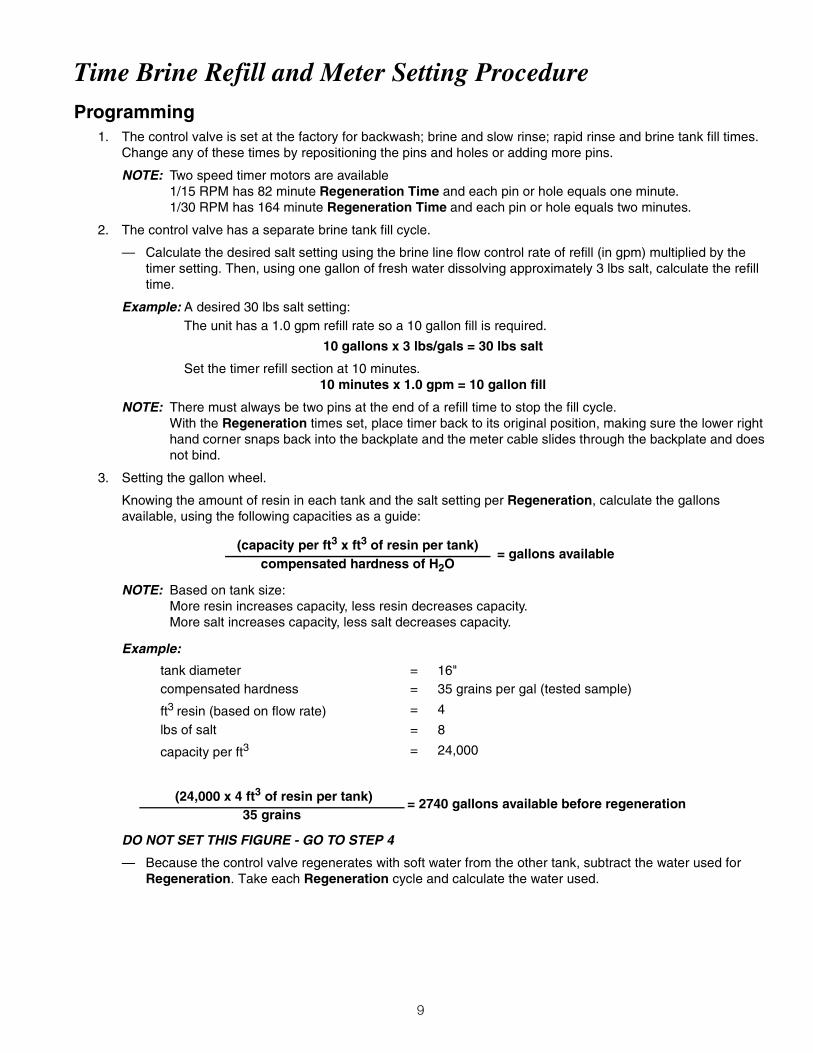
Time Brine Refill and Meter Setting ProcedureProgramming
1. The control valve is set at the factory for backwash; brine and slow rinse; rapid rinse and brine tank fill times. Change any of these times by repositioning the pins and holes or adding more pins.
NOTE: Two speed timer motors are available1/15 RPM has 82 minute Regeneration Time and each pin or hole equals one minute.1/30 RPM has 164 minute Regeneration Time and each pin or hole equals two minutes.
2. The control valve has a separate brine tank fill cycle.
— Calculate the desired salt setting using the brine line flow control rate of refill (in gpm) multiplied by the timer setting. Then, using one gallon of fresh water dissolving approximately 3 lbs salt, calculate the refill time.
Example: A desired 30 lbs salt setting:The unit has a 1.0 gpm refill rate so a 10 gallon fill is required.
10 gallons x 3 lbs/gals = 30 lbs salt
Set the timer refill section at 10 minutes.10 minutes x 1.0 gpm = 10 gallon fill
NOTE: There must always be two pins at the end of a refill time to stop the fill cycle.With the Regeneration times set, place timer back to its original position, making sure the lower right hand corner snaps back into the backplate and the meter cable slides through the backplate and does not bind.
3. Setting the gallon wheel.
Knowing the amount of resin in each tank and the salt setting per Regeneration, calculate the gallons available, using the following capacities as a guide:
NOTE: Based on tank size:More resin increases capacity, less resin decreases capacity.More salt increases capacity, less salt decreases capacity.
Example:
DO NOT SET THIS FIGURE - GO TO STEP 4
— Because the control valve regenerates with soft water from the other tank, subtract the water used for Regeneration. Take each Regeneration cycle and calculate the water used.
(capacity per ft3 x ft3 of resin per tank)= gallons available
compensated hardness of H2O
tank diameter = 16"compensated hardness = 35 grains per gal (tested sample)
ft3 resin (based on flow rate) = 4
lbs of salt = 8
capacity per ft3 = 24,000
(24,000 x 4 ft3 of resin per tank) = 2740 gallons available before regeneration35 grains

10
Model 9000/9100/9500
11
Example: Unit is set for a 16" diameter tank with 4 ft3 of resin and salted at 8 lbs. per ft3, 7 gpm backwash, #3 injector, 1.0 gpm brine refill, and 60 psi and timer set for 10 min. backwash, 60 min. brine and rinse, 10 min. rapid rinse, 10 min. brine tank fill.
With the 2740 gallons available calculated in Step 3, subtract the Regeneration water used from the total water available.
4. Set meter wheel at approximately 2530 gallons. Lift the inner dial of the meter program wheel so that you can rotate it freely. Position the white dot opposite the 2530 gallon setting.
NOTE: There is a slight delay between the time the meter zeros out and the cycle starts. Units using the: 1/15 RPM motor, 82 minute Regeneration Time has a 9 minute delay1/30 RPM motor, 180 minute Regeneration Time has an 18 minute delay.
This delay period is not critical on residential equipment. However, take this factor into consideration for commercial applications by subtracting continuous flows for 9 minutes or 18 minutes from water available.
5. Insert meter cable into meter.
6. Check bypass.
7. Plug in unit.
Backwash 10 minutes x 7.0 gpm = 70.0 gallonsBrine and Rinse 60 minutes x 1.0 gpm = 60.0 gallons
Rapid Rinse 10 minutes x 7.0 gpm = 70.0 gallonsBrine Tank Fill 10 minutes x 1.0 gpm = 10.0 gallons
Total Regeneration Water = 210.0 gallons
2740 gallons available - 210 gallons used = 2530 gallons(in Regeneration, Step 4)

11
Model 9000/9100/9500
22
9000/9100/9500 Electro Mechanical Timer Assembly
Figure 21
9100ElectroMechanicalTimerAssembly

12
Item QuantIty Part number DescrIPtIon
1 1 13870-03 timer housing assembly.2 1 17870 label, capacity gallons3 1 15465 label, Caution4 1 16930 label, Instruction5 1 15227 actuator plate6 1 10300 screw, hex washer #87 1 17513 spring clip8 1 15407 washer, plain #49 1 15228 spring10 1 16270-10 gallon wheel assembly 3/4" standard range meter
16270-50 gallon wheel assembly 3/4" extended range meter16270-30 gallon wheel assembly 1" standard range meter16270-40 gallon wheel assembly 1" extended range meter
11 1 13806 program wheel retainer12 1 13748 screw, flathead #6-2013 2 11999 button decal14 1 15223 cycle actuator gear15 1 13886-01 knob16 4 13296 screw, hex washer #6-2017 1 17724 drive pinion18 1 17723 drive pinion clutch19 1 14276 spring, meter clutch20 1 14253 retainer21 3 14087 insulator22 1 15314 switch23 1 15320 switch24 2 11413 screw, pan head #4-4025 1 13018 idler shaft26 1 18563 spring, idler shaft27 1 13017 idler gear28 1 13164 drive gear29 1 13887 motor mounting plate30 1 18743 motor, 120V 60 Hz.-1/30 RPM
18824 motor, 220V 50 Hz.-1/30 RPM19170 motor, 120V 60 Hz.-1/15 RPM18825 motor, 220V 50 Hz.-1/15 RPM
31 2 13278 screw, #6-3232 1 14265 spring clip33 1 15055 main drive gear34 1 19210-02 program wheel, 90 minute
19210-05 program wheel, 180 minute35 23 15493 roll pin36 1 15203 harness37 2 12681 wire nut38 1 60320-02 auxiliary timer switch kit (not shown)
9100ElectroMechanicalTimerAssembly

13
Model 9000/9100/9500
24
9000/9100/9500 Power Head
Figure 22
9100ElectroPowerHead
14
Item QuantIty Part number DescrIPtIon
1 2 18728 nut, clip #8-322 1 11838 power cord, 6' U.S. 120V
11839 power cord, 12' U.S.120V11545-01 power cord, 5' European 220V
14678 power cord, 6' U.S. 220V19303-01 power cord, Australian 8' 220V
19674 transformer, U.S., 110V to 24V25651 transformer, European, 220V to 24V
3 1 15202 wire harness, mechanical14822 wire harness auxiliary drive switch
4 1 15134 drive gear assembly, lower5 1 15135 drive gear assembly6 1 14896 geneva wheel7 2 40422 wire connector8 2 19367 cover screw9 1 15175 position decal10 2 14917 retaining ring11 1 15199 ground plate12 1 14430 screw, hex washer #613 2 19160 screw, motor mounting14 1 18737 drive motor, 24V, 50/60 Hz (red wires)
1 18738 drive motor, 120V, 60 Hz (black wires)1 18739 drive motor, 220V, 50 Hz (yellow wires)
15 1 15131 backplate, mechanical and SE16 2 15172 screw, flat head #4-4017 2 10340 washer, lock #418 10218 micro switch (homing)19 1 10339 nut, micro switch20 1 15331 screw, valve mounting21 2 15133 drive gear assembly, upper22 1 13547 strain relief23 1 15810 retaining ring, drive gear24 1 15132 triple cam (9000/9100)25 1 15638 cable guide (9000/9100)26 2 15372 washer, thrust27 1 15216 meter cable, 15.25", 1" meter, mechanical
15425 meter cable, 13.25", 3/4" meter, mechanical28 2 15692 spacer29 1 16433 micro switch (program)30 1 10302 insulator31 2 15173 screw
Not Shown32 1 60232-110 cover, black
1 60232-112 cover, black - left window33 1 60320-09 optional auxiliary drive switch (9000/9100)
9100PowerHead

15
Model 9000/9100/9500
28
9100 Control Valve Assembly
Figure 24
9100ControlValveAssembly

16
Model 9000/9100/9500
29
9100 Control Valve AssemblyItem Quantity Part Number Description1 1 40688 valve body assembly2 4 15137 screw, hex washer #10-24 x 3/8”3 1 14906 end plate4 1 14928 end plug5 1 19054 O-ring, 1246 1 18303 O-ring, 3367 1 40538 retainer, 32mm8 1 60400 piston top assembly9 1 60125 seal and spacer kit, top
1 60125-20 seal and spacer kit, top (559PE)10 1 60421 seal and spacer kit, bottom
1 60421-20 seal and spacer kit, bottom (559PE)11 1 60401 piston assembly, bottom12 1 60385-XXXX injector assembly
(see following chart for dash numbers)injector number DLFC number BLFC numberred #0 00 Blank 0 Blank 0
white #1 01 1.2 1 0.25 1 blue #2 02 1.5 2 0.50 2
yellow #3 03 2.0 3 1.00 3 green #4 04 2.4 4
3.0 53.5 64.0 75.0 87.0 9
12A 1 60022-12 brine line flow control assembly, 0.125 gpm60022-25 brine line flow control assembly, 0.250 gpm60022-50 brine line flow control assembly, 0.500 gpm60022-100 brine line flow control assembly, 1.00 gpm
12B 1 60350 brine valve assembly13 1 61419 distributor adapter kit, 1.05"
Not Shown14 12763 seal and space stuffer tool15 13061 spacer puller tool16 13759 DLFC retainer tool
9100ControlValveAssembly

17
Figure 29
9100SecondTankAssembly
1 2
3
Item QuantIty Part number DescrIPtIon
1 1 60425-12 plastic tube assembly, 9100, up to 12" tanks60425-16 plastic tube assembly, 9100, up to 16" tanks
2 1 14865 second tank adapter assembly, 91003 1 61419 distributors adapter kit, 9100, 1.05"
9100SecondTankAssembly

18
Figure 31
9000/9100/9500 Meter Assemblies9100MeterAssembly

19
Item QuantIty Part number DescrIPtIon
1 1 60086 3/4" meter assembly, standard range60087 3/4" meter assembly, extended range
1A 1 14038 meter cap assembly, standard range1C 15150 meter cap assembly, extended range1D 1 15218 meter cap assembly, brass standard range
15218NP meter cap assembly, brass nickel-plated standard range
1E 15237 meter cap assembly, brass extended range
15237NP meter cap assembly, brass nickel-plated extended range
2 1 13509 impeller13509-01 impeller, hot water
4 1 60389 1" meter assembly, standard range60389NP 1" meter assembly, standard range
60390 1" meter assembly, extended range
60390NP 1" meter assembly, extended range, nickel-plated
60612 1" meter assembly, standard range, hot water4A 1 15078 1" adapter coupling
Not Shown7 60460 meter checker kit, standard range8 60461 meter checker kit, extended range
9100MeterAssembly

20
Model 9000/9100/9500
36
9000/9100 Bypass Valve
Figure 34
Item Quantity Part Number Description1 1 60040SS 3/4" bypass valve NPT
60040-10 3/4" bypass valve BSP60041SS 1" bypass valve NPT60041-10 1" bypass valve BSP
2 1 60049 plastic bypass valveNot Shown3 40157 plastic bypass T-handle wrench
9100BypassValve

21
Model 9000/9100/9500
37
2310 Safety Brine Valve
Figure 35
Item Quantity Part Number Description1 1 60014 2310 safety brine valve2 1 60068 2310 float assembly
60026-30 float assembly red/white (float fill)3 1 60002 #500 air check
2310SafetyBrineValve
22
Model 9000/9100/9500
40
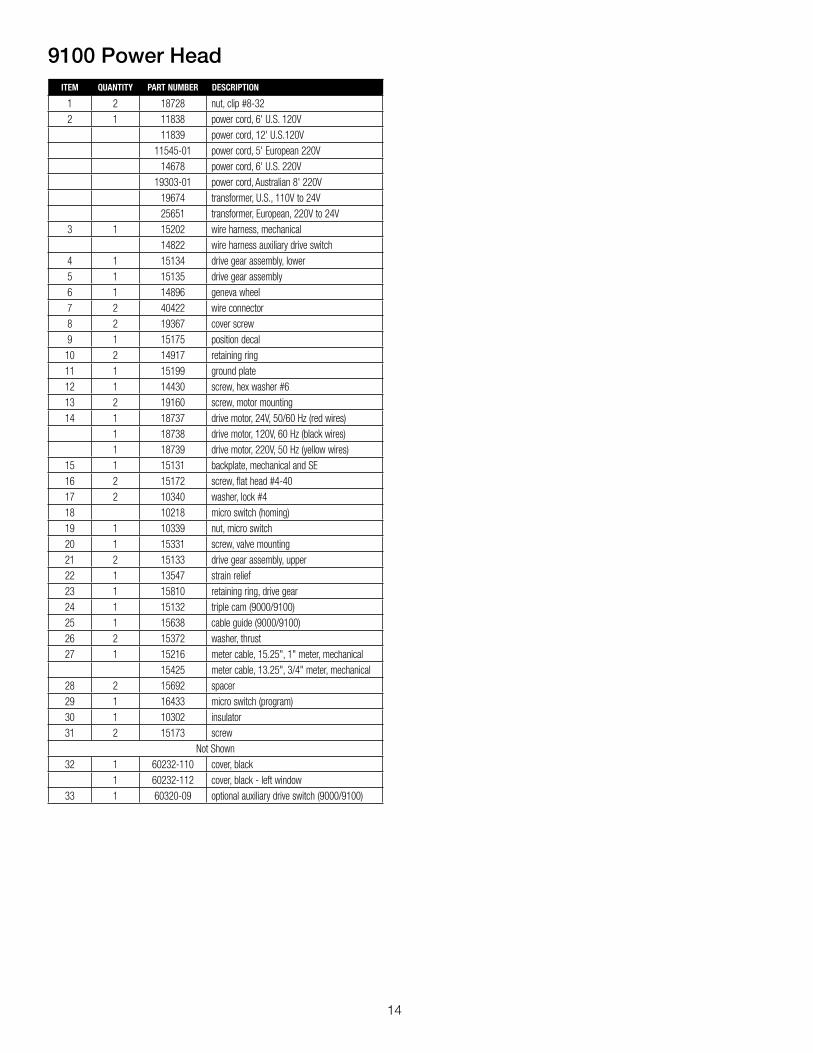
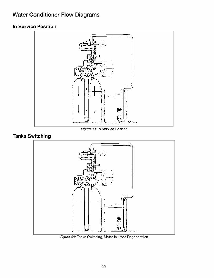
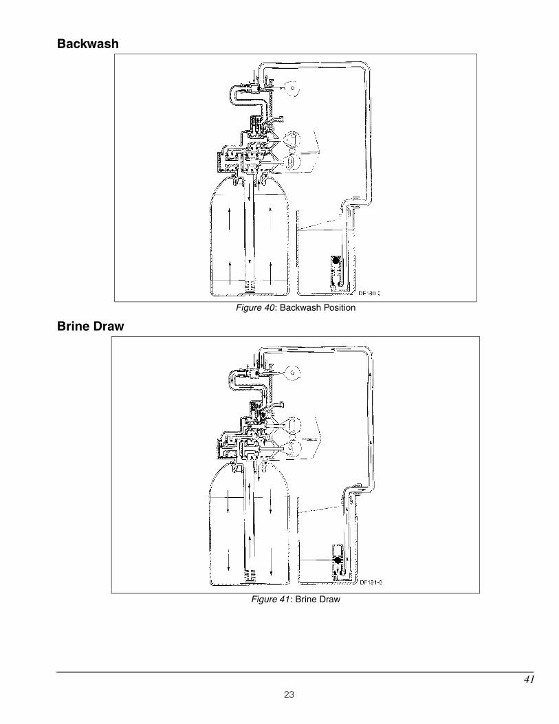
Water Conditioner Flow DiagramsIn Service Position
Tanks Switching
Figure 38: In Service Position
Figure 39: Tanks Switching, Meter Initiated Regeneration
WaterConditionerFlowDiagrams
23
Model 9000/9100/9500
41
Backwash
Brine Draw
Figure 40: Backwash Position
Figure 41: Brine Draw

24
Model 9000/9100/9500
42
Slow Rinse
Rapid Rinse
Figure 42: Slow Rinse
Figure 43: Rapid Rinse

25
Model 9000/9100/9500
43
Brine Tank Fill Position
In Service, Tanks Switched
Figure 44: Brine Tank Fill Position
Figure 45: In Service, Tanks Switched

26
Model 9000/9100/9500
44
Troubleshooting
PROBLEM CAUSE CORRECTION
1. Softener fails to regenerate. A. Electrical service to unit has been interrupted.
B. Timer is defective.
A. Assure permanent electrical service (check fuse, plug, pull chain or switch).
B. Replace timer.
2. Hard water. A. Bypass valve is open.B. No salt in brine tank.
C. Injector screen plugged.D. Insufficient water flowing into brine
tank.E. Hot water tank hardness.
F. Leak at distributor tube.
G. Internal valve leak.
A. Close bypass valve.B. Add Salt to brine tank and maintain
salt level above water level.C. Clean injector screen.D. Check brine tank fill time and clean
brine line flow control if plugged.E. Repeated flushing of the hot water
tank is required.F. Make sure distributor tube is not
cracked. Check O-Ring and tube pilot.
D. Replace seals and spacers and/or piston.
3. Unit used too much salt. A. Improper salt setting.B. Excessive water in brine tank.
A. Check salt usage and salt setting.B. See Problem No. 7.
4. Loss of water pressure. A. Iron buildup in line to water conditioner.
B. Iron buildup in water conditioner.
C. Inlet of control plugged due to foreign material broken loose from pipe by recent work done on plumbing system.
A. Clean line to water conditioner.
B. Clean control and add mineral cleaner to mineral bed. Increase frequency of regeneration and/or backwash time.
C. Remove pistons and clean control.
5. Loss of mineral through drain line. A. Air in water system.
B. Drain line flow control too large.
A. Assure that well system has proper air eliminator control. Check for dry well condition.
B. Check to ensure drain line flow control is sized properly for your mineral tank.
6. Iron in conditioned water. A. Fouled mineral bed. A. Check backwash, brine draw and brine tank fill. Increase frequency of regeneration.
7. Excessive water in brine tank. A. Plugged drain line flow control.B. Plugged injector system.C. Timer not cycling. D. Foreign material in brine valve.
E. Foreign material in brine line flow control.
F. Power loss during brine fill.
A. Check flow control.B. Clean injector and screen.C. Replace timer.D. Replace brine valve seat and clean
valve.E. Clean brine line flow control.
F. Check power source.

27
Model 9000/9100/9500
45
General Service HintsProblem: Softener delivers hard water
PROBLEM CAUSE CORRECTION
8. Softener fails to draw brine. A. Drain line flow control is plugged.B. Injector is plugged.C. Injector screen plugged.D. Line pressure is too low.
E. Internal Control Leak
A. Clean drain line flow control.B. Clean injector.C. Clean screen.D. Increase line pressure to
25 psi min.E. Change seals, spacers and piston
assembly.
9. Control cycles continuously. A. Broken or shorted switch. A. Determine if switch or timer is faulty and replace it, or replace complete power head.
10.Drain flows continuously. A. Valve is not programming correctly.
B. Foreign material in control.
C. Internal control leak.
A. Check timer program and positioning of control. Replace power head assembly if not positioning properly.
B. Remove power head assembly and inspect bore, remove foreign material and check control in various regeneration positions.
C. Replace seals and piston assembly.
PROBLEM CAUSE CORRECTION
Softener delivers hard water. Reserve capacity has been exceeded. Check salt dosage requirements and reset program wheel to provide addi-tional reserve.
Program wheel is not rotating with meter output.
Pull cable out of meter cover and rotate manually. Program wheel must move without binding and cycle actuator must start the cycle before the clutch releases.
Meter is not measuring flow. Check output by observing rotation of small gear on front of timer
(Note: Program wheel must not be against regeneration stop for this check)
Each tooth is approximately 75 gallons on 1-1/2″ installations. If not performing properly, replace meter.
28
Model 9000/9100/9500
46
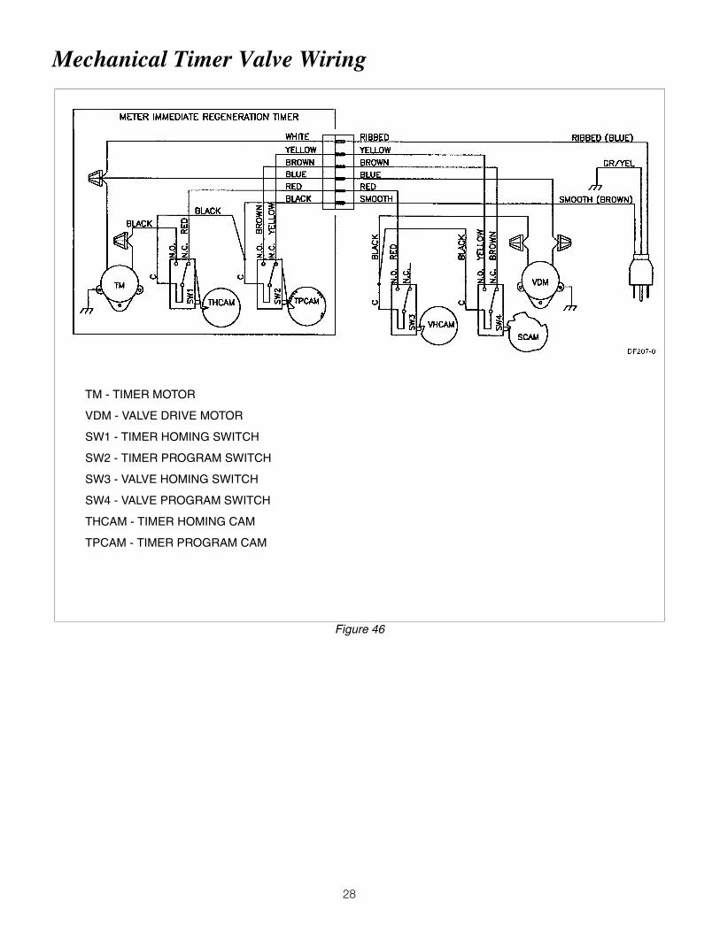
Mechanical Timer Valve Wiring
Figure 46
TM - TIMER MOTOR
VDM - VALVE DRIVE MOTOR
SW1 - TIMER HOMING SWITCH
SW2 - TIMER PROGRAM SWITCH
SW3 - VALVE HOMING SWITCH
SW4 - VALVE PROGRAM SWITCH
THCAM - TIMER HOMING CAM
TPCAM - TIMER PROGRAM CAM

29
Model 9000/9100/9500
50
9100 Control Dimensions
Figure 50

30
Model 9000/9100/9500
53
9100
9500
Figure 53: 9100 Meter Flow Data
Figure 54: 9500 Meter Flow Data

31
Model 9000/9100/9500
54
Injector Flow Data9000/9100
Figure 55: 9000/9100—1600 Series Injectors
InjectorFlowData9100

IOM-WQ-PWSTA 1225 EDP# 2915896 © 2012 Watts
USA: Tel. (800) 224-1299 • www .watts .com Canada: Tel. (888) 208-8927 • www .watts .ca
A Watts Water Technologies Company
LImIteD Warranty: Certain Watts Pure Water products come with a limited warranty from Watts Regulator Co. Other products may have no warranty or are covered by the original manufacturer’s warranty only. For specific product warranty information, please visit www.watts.com or the published literature that comes with your product. Any remedies stated in such warranties are exclusive and are the only remedies for breach of warranty. eXcePt For tHe aPPLIcabLe ProDuct Warranty, IF any, Watts maKes no otHer WarrantIes, eXPress or ImPLIeD. to tHe FuLLest eXtent PermItteD by aPPLIcabLe LaW, Watts Hereby sPecIFIcaLLy DIscLaIms aLL otHer WarrantIes, eXPress or ImPLIeD, IncLuDInG but not LImIteD to tHe ImPLIeD WarrantIes oF mercHantabILIty anD FItness For a PartIcuLar PurPose, anD In no eVent sHaLL Watts be LIabLe, In contract, tort, strIct LIabILIty or unDer any otHer LeGaL tHeory, For IncIDentaL, InDIrect, sPecIaL or conseQuentIaL DamaGes, IncLuDInG, WItHout LImItatIon, Lost ProFIts or ProPerty DamaGe, reGarDLess oF WHetHer It Was InFormeD about tHe PossIbILIty oF sucH DamaGes.