Embed Size (px)
Citation preview

Series FCU6x00/FCU-EXT-APP
Installation and Operating Manual
FCU6x00
FCU-EXT-APP-CONTROL can be combined with the following sauna control units in the FCU series:
Series FCU3000 FCU3200 FCU3400
Series FCU4000 FCU4200 FCU4400
Series FCU5000 FCU5200 FCU5400
Series FCU6000 FCU6200 FCU6400
Doc-ID: B_FCU-EXT-APP
Version: V 1.03
Technical changes and errors excepted, illustration similar.

Table of contents
Installation and Operating Manual / Version V 1.03 3
Table of contents
1 Safety ................................................................................................................................ 5
1.1 Explanation of symbols ................................................................................. 5
1.2 Safety-related assembly and installation instructions................................... 6
1.3 Intended use ................................................................................................. 6
1.4 Changes and alterations ............................................................................... 6
1.5 Requirements for the operator and technicians ........................................... 7
1.6 Occupational safety and special risks .......................................................... 7
1.7 Information about the operating manual and installation instructions .......... 8
2 Installation instructions ................................................................................................ 10
2.1 Schematic connection of the components .................................................. 10
2.2 Installing the interface converter ................................................................. 11
3 Connection and initial set-up by service technician ................................................. 12
3.1 Components ............................................................................................... 12
3.1.1 Connect Box .......................................................................................... 12
3.1.2 Mains adapter ........................................................................................ 13
3.1.3 Interface converter................................................................................. 13
3.1.4 USB cable .............................................................................................. 13
3.2 Connection and initial operation ................................................................. 13
3.3 Initial set-up with LAN operation ................................................................. 13
3.4 Initial set-up with WLAN operation ............................................................. 14
3.5 Switching off or restarting the Connect Box ............................................... 15
3.6 Connecting to the "SaunaControl" App ...................................................... 15
3.7 Use of the sub-user function ....................................................................... 16
4 Technical data ............................................................................................................... 16
5 Structure and function .................................................................................................. 17
5.1 Function ...................................................................................................... 17
5.2 Operating keys for the sauna control unit ................................................... 17
5.3 Operating keys for App Control .................................................................. 18
5.3.1 Symbols in the status bar ...................................................................... 19
6 Operation ....................................................................................................................... 20
6.1 Safety and instructions ............................................................................... 20
6.2 Switching the sauna control unit on and off ................................................ 21
6.2.1 Switching on the sauna control unit ....................................................... 21
6.2.2 Switching off the sauna control unit ....................................................... 21
6.3 Setting bath mode....................................................................................... 22
6.4 Menu: settings ............................................................................................ 23
6.4.1 Fan and light settings ............................................................................ 23
6.4.2 Setting the timer .................................................................................... 24
6.4.3 Aroma settings (optional) ...................................................................... 24
6.4.4 Coloured light settings (optional) ........................................................... 24

Table of contents
4 Installation and Operating Manual / Version V 1.03
6.5 Menu: Basic settings .................................................................................. 25
6.5.1 Info menu .............................................................................................. 25
6.5.2 Maximum permissible heating period ................................................... 25
7 Maintenance .................................................................................................................. 26
8 Faults ............................................................................................................................. 26
8.1 Safety ......................................................................................................... 26
8.2 Messages and instructions on the display ................................................. 27
8.3 Acknowledge message .............................................................................. 27
8.4 Error messages .......................................................................................... 27
8.5 Acknowledge error message ..................................................................... 29
9 Decommissioning and disposal ................................................................................. 29
10 General 29
10.1 Limitation on liability ................................................................................... 29
10.2 Copyright protection ................................................................................... 30
10.3 Scope of delivery ....................................................................................... 30
10.4 Spare parts ................................................................................................ 30
10.5 Customer service ....................................................................................... 30
11 Settings 31
11.1 Adjusting range: sauna .............................................................................. 31
11.2 Adjusting range: Sauna with humidity ........................................................ 31
11.3 Adjusting range: Infrared ........................................................................... 31
12 Declaration of Conformity ........................................................................................... 32

Safety
Installation and Operating Manual / Version V 1.03 5
1 Safety
Important safety instructions
Read this manual carefully and keep it for future reference.
1.1 Explanation of symbols
Warnings Warning are marked by symbols in this manual. The instructions in this operating manual are introduced by signal words that indicate the severity of the danger.
Always follow the safety notes and proceed with caution in order to avoid any accidents, personal injuries and damage to property.
DANGER!
... shows an imminently hazardous situation that can result in severe
injuries or even death, if not avoided.
WARNING!
... shows a potentially hazardous situation that can result in severe
injuries or even death, if not avoided.
CAUTION!
... shows a potentially hazardous situation that can result in minor inju-
ries, if not avoided.
WARNING!
... shows a potentially hazardous situation that can result in property
damage, if not avoided.
Tips and suggestions
NOTE!
... underlines useful tips and suggestions as well as information for
efficient and proper operation.

Safety
6 Installation and Operating Manual / Version V 1.03
1.2 Safety-related assembly and installation instructions
– DANGER!
– The control unit can be mounted directly on the outside of the cabin
or at another location, but not inside the cabin
– The control unit may be operated with a cover guard for the oven only
if one of the following options is available:
Timer function (can be locked in the service menu)
Remote start (remote operation) via option input or WEB-/APP-
Control
– According to VDE, for public saunas, an indicator lamp indicating that
the heater is switched on must be installed in the supervisor's room.
– This lamp can be connected to the clamp (FLE-STB).
– To disconnect from the mains, the power supply line must be
equipped with a fuse having a contact opening according to the re-
quirements of overvoltage category III for full separation.
– The main switch of the control unit must be freely accessible for de-
vices of the FCUxxxx series.
– The temperature sensor must be installed in such a way that it is not
affected by cold air flowing in from the outside.
1.3 Intended use
The FASEL sauna control units in the FCUxx00 series are designed exclusively for op-
eration and control of sauna cabins, saunas with humidity and infrared cabins. The con-
trol units are approved for operation in private homes and businesses.
Intended use
WARNING!
Danger if used other than for intended purpose!
Any use apart from the intended use and/or any other use of the sauna
control system can result in dangerous situations.
For this reason:
– Use sauna control unit only as intended.
– The sauna control unit may be operated only within the permissible
ambient temperature limits and humidity limits.
– All specifications in the operating manual and installation instructions
must be strictly adhered to.
Claims of any kind due to damage as a result of non-intended use are excluded. The
operator bears sole responsibility for any damage caused by non-intended use.
1.4 Changes and alterations
Changes and alterations to the sauna control unit or to the installation can lead to un-
foreseen dangers.
Always obtain the written permission of the manufacturer before any technical changes
and alterations are made to the sauna control unit.

Safety
Installation and Operating Manual / Version V 1.03 7
1.5 Requirements for the operator and technicians
This device can be used by children aged 8 years and above and persons with reduced
physical, sensory or mental capabilities or lack of experience and knowledge if they
have been given supervision or instruction concerning the safe use of the device and
understand the hazards involved. Children should not play with the device. Cleaning
and user maintenance should not be carried out by children without supervision.
Read this operating manual carefully before switching on. Adherence to all the safety
and operating instructions specified in this operating manual is a basic prerequisite for
safe operation and safe working.
Please contact your customer service in case of doubts.
Inadequate qualification
WARNING!
Risk of injury in case of inadequate qualification!
Improper handling could lead to considerable personal injuries and
damage to property.
For this reason:
Assembly, installation, initial operation as well as troubleshooting,
maintenance and repairs must be carried out by qualified persons
only, unless otherwise specified.
1.6 Occupational safety and special risks
The safety notes and warnings specified here and in the following sections of this man-
ual must be taken into account in order to reduce health hazards and avoid dangerous
situations.

Safety
8 Installation and Operating Manual / Version V 1.03
The following instructions are for your own safety and for the safety of the sys-
tem and must be adhered to:
Electric voltage
DANGER!
Danger to life due to electric shock.
There is imminent danger to life in case of direct contact with live parts.
Damage of insulation or individual parts could pose danger to life.
For this reason:
– To disconnect from the mains, the power supply line must be
equipped with a fuse having a contact opening according to the re-
quirements of overvoltage category III for full separation.
– Disconnect power supply to the system before any work (switch off
the fuse in the junction box) and secure against restarting. Check if
the equipment is disconnected from the power supply. Disconnect the
control unit from the mains before opening the housing.
– In case of damage to the insulation, immediately switch off power
supply and initiate repairs.
– Works on electrical machinery should be carried out only by skilled
personnel.
– Never bypass or switch off fuses.
– Adhere to the correct current specification while changing the fuses.
– Keep moisture away from live parts as it can lead to short-circuits.
WARNING!
If there is a short-circuit in a 230V/400V load, the contact of a relay
can fuse due to the high short-circuit current. Even the safety relay
can fuse if restarted before removing the short-circuit. This will
lead to steady state of the consumer. Switch off the automatic cir-
cuit breaker in the junction box. Send the device back to the facto-
ry for checking/repair.
Improper opera-tion
WARNING!
Improper operation can result in serious injuries.
For this reason:
– Read and follow the operating manual.
1.7 Information about the operating manual and installation instructions
This FASEL control unit comes with an operating manual and installation instructions.
The operating manual is intended for users and provides important advice on handling
the FASEL control unit.
The installation instructions describe the process of assembly, installation, initial opera-
tion, troubleshooting and repairs and are intended exclusively for professionals.

Safety
Installation and Operating Manual / Version V 1.03 9
Adherence to all the safety and operating instructions specified in this operating manual
is a basic prerequisite for safe operation and safe working.
In addition, the local accident prevention regulations and general health and safety re-
quirements must be adhered to wherever the control unit is in use.
Read this operating manual carefully before switching on. The operating manual and in-
stallation instructions are integral parts of this product and must be kept accessible at all
times in the immediate vicinity of the control unit.
The device can have more or less connection options and functions, depending on the
version. Depending on the variant, the key(s) and display inscriptions may also be indi-
vidually designed and may deviate from the figures.
If the control unit is passed on to third parties, the operating manual and the installation
instructions must also be handed over.
Components by other providers have their own operating manuals, as well as safety re-
quirements and regulations that must also be adhered to.

Installation instructions
10 Installation and Operating Manual / Version V 1.03
2 Installation instructions
2.1 Schematic connection of the components
Sauna area: Control unit: Sauna, Steam bath
dry and frost-free room: Connect Box
Fig. 1: Schematic lay-out FCU-EXT-APP-CONTROL

Installation instructions
Installation and Operating Manual / Version V 1.03 11
2.2 Installing the interface converter
Fig. 2: Installing FCU-EXT-APP-CONTROL-CONVERTER

Connection and initial set-up by service technician
12 Installation and Operating Manual / Version V 1.03
3 Connection and initial set-up by service technician
3.1 Components
The following components are available:
Connect Box
Mains adapter with USB cable
Interface converter
USB cable
3.1.1 Connect Box
Fig. 3: Connect Box front panel (Version 1/2)
Fig. 4: Connect Box rear view (Version 1/2)
The LAN and USB ports are located on the front panel. This USB port is for connecting
to the interface converter. When the LAN connection is active, the LEDs on the LAN
port will flash.
The rear panel has the connector for the USB mains adapter (Power). The WLAN an-
tenna is also located on the rear panel. This can be aligned. Please always make sure
that the antenna is fixed via the nut!

Connection and initial set-up by service technician
Installation and Operating Manual / Version V 1.03 13
3.1.2 Mains adapter
Mains adapter for supplying the Connect Box via a USB cable.
3.1.3 Interface converter
Interface converter between sauna unit FCUxxxx and Connect Box.
3.1.4 USB cable
USB cable (3m) for connection between Connect Box and interface converter.
3.2 Connection and initial operation
Connection and initial operation of the individual components:
1. Please insert the interface converter in the FCU control.
Connect the interface converter to the FCU slot "FB-BUS".
2. Please connect the Connect Box to the interface converter via the USB port. USB
port may not be changed during operation. If this happens, the Connect Box must
be restarted.
3. Only for LAN operation:
Connect the LAN cable from the Connect Box to your in-house network (LAN). This
connection can be made to a router or network switch.
Only for WLAN operation:
Ensure that you have stable WLAN reception.
If necessary, the WLAN antenna can be rotated 360° after loosening the nut. En-
sure that you tighten the nut firmly afterwards.
4. Please connect the USB mains adapter to the Connect Box. The Connect Box
starts automatically after it has been plugged in.
5. Setting up the Connect Box.
NOTE!
Please note that a DHCP server must be enabled in the in-house LAN.
In most cases, this function is performed by the connected router (or, in
some company networks, by a corresponding network server).
3.3 Initial set-up with LAN operation
The Connect Box automatically connects to the cloud server when there is an Internet
connection. No further set-up is necessary. If successfully connected to the cloud serv-
er, the FCU will give 3 beeps as feedback.
You can connect directly to the sauna via the App.

Connection and initial set-up by service technician
14 Installation and Operating Manual / Version V 1.03
3.4 Initial set-up with WLAN operation
NOTE!
Please have your personal WLAN password ready for set-up via WLAN.
During initial operation, the Connect Box must be connected to the existing WLAN.
1. Start the Connect Box by briefly disconnecting it from the power supply and plug-
ging it in again.
After it is switched on, the Connect Box searches for all available WLAN connec-
tions. The Connect Box then opens its own WLAN "CONNECT-BOX".
Note: This WLAN is only required for setting the Connect Box. It is only available
for 3 minutes once the "Connect Box" has been found by your Smartphone/Tablet.
Please perform the following steps (2-5) within these 3 minutes.
2. Please connect to the WLAN "CONNECT-BOX".
To do this, open the WLAN menu in your Smartphone/Tablet:
Settings WLAN Search WLAN
Connect to "CONNECT-BOX"
The password required for this is: "11111111"
Note: This WLAN does not have Internet access. Any warnings that your
Smartphone/Tablet is not connected to the Internet can be ignored or, if you are
prompted to do so, this message must be confirmed.
Note: Check that you are still connected to the WLAN "CONNECT-BOX".
Note: After a repeated connection with "CONNECT-BOX", the password may be
saved and does not have to be entered again.
3. On your Smartphone/Tablet, open the Internet browser (e.g., Safari or Chrome) and
open the following page in the address bar: "http://10.42.0.1"
4. Select your own home WLAN from the list and enter your personal WLAN password.
Then press "Save & Restart".
If your WLAN is not listed, check the WLAN signal strength!
After saving you lose the connection to the Connect Box, which can lead to an error
message in your browser.
Note: Remember to reconnect your Smartphone/Tablet to your home WLAN.
5. After saving the settings successfully, the Connect Box automatically connects to
your in-house WLAN and afterwards to the cloud server.
The sauna control unit gives the following feedback signals on these three process-
es via the buzzer:
1x beep: Settings saved.
Note: If this 1x beep is not heard, you may have taken too long or are too far away
from the Connect Box. In this case, you must start again from step 1.
2 x beeps: WLAN connection successfully established.
Note: If the 2x beeps are not heard, the Connect Box has not connected to your in-
house WLAN. You may not have enough WLAN reception or a wrong WLAN pass-
word. You may need to move the Connect Box to another location. Please check
both and start again at step 1.

Connection and initial set-up by service technician
Installation and Operating Manual / Version V 1.03 15
3 x beeps: Server connection successfully established. Now you can connect to the
App. This process can take about 5 minutes.
Note: If the 3x beeps are not heard, the Connect Box has not been able to establish
a connection to the server. Check for a stable Internet connection and possible secu-
rity settings on the WLAN router. In this case, start the Connect Box by briefly dis-
connecting it from the power supply and plugging it in again. The Connect Box
should now automatically connect to your WLAN and try to establish a connection to
the server.
6. After you have successfully connected to the server, you can connect to the sauna
via the App.
3.5 Switching off or restarting the Connect Box
The Connect Box is switched on/off by plugging in/unplugging the USB mains adapter.
3.6 Connecting to the "SaunaControl" App
WARNING!
Important access code for your sauna!
Your access code is unique to your sauna control unit and gives you
and others access to your sauna. Please keep it safe and do not pass it
on to third parties. This access cannot be blocked and is intended only
for the owner of the sauna.
For other users, we recommend the sub-user function.
NOTE!
Please note that after a restart or power failure, the Connect Box takes
about 5 minutes to connect to the server and be accessible from the
App.
Only after this period is the Connect Box ready for operation and can be
controlled or accessed using the following method.
To control the sauna, you must connect your App to the sauna control unit.
1. Please check that the sauna control unit is on. In addition, the Connect Box must be
plugged in and connected to the server.
2. Please install the "SaunaControl" App
The App can be downloaded from the official app stores of
Google (Android) and Apple (iOS).
3. Open the "SaunaControl" App on your Smartphone/Tablet.
4. Press "Connect to cloud"
5. Press "Scan QR Code" and scan your QR connection code.
The first time you connect to the main user you will need the access code.

Technical data
16 Installation and Operating Manual / Version V 1.03
The access code is on the supplement!
For sub-user access you do not need an access code.
6. The App automatically connects to your sauna.
7. The sauna is additionally protected with a PIN. This is the same for all users.
As delivered, this PIN is set to "0000".
8. You will be asked to assign a PIN when you connect for the first time.
Please make a note of this PIN. It can be reset only on a sauna control unit with an
operating element or by a service engineer!
9. To disconnect, open the side menu and press
10. You can access your sauna at any time via "Known devices".
NOTE!
In addition, a protection module is installed to protect against changes
to the software components. Any change by the sales department or
end customer is prohibited and will lead to a loss of function of the sys-
tem in the event of a violation. We can detect a change. In such a case,
there will be a charge for repairing the software.
3.7 Use of the sub-user function
The sub-user function creates secure and controlled access for other people. The ac-
cess included with the App-Control is always the main user. The main user will be able
to create and delete further accesses. For safety reasons, only the main user has this
authorisation.
To create a sub-user, proceed as follows:
1. Connect to your sauna as the main user in the App.
2. Select the menu item User in the side menu
3. Use to add another user.
4. The corresponding access is displayed as a QR code.
5. You can also remove a user with .
Note: A user who has been deleted cannot be restored.
The corresponding user will no longer have access to the sauna.
4 Technical data
Description Type
Max. distance FCUxxxx to CONNECT BOX
3m USB cable
Power supply Only with the enclosed USB mains adapter
Ambient temperature 0 to +40 °C
Rel. humidity max. 80 % rel. humidity, not condensing

Structure and function
Installation and Operating Manual / Version V 1.03 17
Storage temperature -10 to +60 °C
Rel. humidity, storage max. 80 % rel. humidity, not condensing
Protection class IP20
CONNECT BOX dimensions W x H x D approx. 55mm x 30mm x 75mm
Table 1: Technical data
Connecting cable switch/router to CONNECT BOX
The LAN cable is not included in the delivery. It can be purchased from electrical retailers.
Specification of the patch cable and LAN cable
At least AWG26
At least CAT 5
Pin 1 to Pin 1 cable configuration (straight through)
WLAN frequency band 2,4 GHz
5 Structure and function
5.1 Function
Depending on the variant of the FCUxxxx control unit, the following bath modes can be
operated with the APP CONTROL:
Sauna
Sauna with humidity
Infrared
Steam bath
In addition, the following settings can be changed depending on the bath mode:
Temperature
Humidity
Heating time / Remaining heating time
5.2 Operating keys for the sauna control unit
Key / Switch Description
Main switch
0 "Power OFF" switch
Use this switch to turn off the mains connec-tion to the control unit and the cleaning light.
I "Control unit power ON" switch
This switches on the power to the control unit.

Structure and function
18 Installation and Operating Manual / Version V 1.03
Key / Switch Description
"Cleaning light ON" switch
Use this switch to switch on the cleaning light.
5.3 Operating keys for App Control
The App is equipped with the following operating keys:
Key / Switch Description
Keys for bath modes
Key "Bath mode Sauna"
Display Meaning
Grey Bath mode not selected.
Press the key to select this bath mode
Blue Bath mode selected.
The bath mode is activated by pressing this key.
Orange Bath mode is active.
The bath mode is deactivated by pressing this key.
Flashing blue/orange
The timer is active.
Bath mode starts at the set time.
Key "Bath mode Sauna with humidity"
Functions as described for "Bath mode Sauna" key.
Key "Bath mode Infrared"
Functions as described for "Bath mode Sauna" key.
Key "Bath mode steam bath" (only FCUX000-STEAM)
Functions as described for "Bath mode Sauna" key.
Keys, Basic functions
Key "Cabin light"
Switches light in the cabin on and off. The light is switched on and off by
pressing this key. To adjust brightness, press and hold the key until the
light settings mode opens.
Key "Control unit standby"
Switches the control unit standby on and off.
The control unit will switch automatically to standby mode if it remains without active program for 2 minutes.
Table 2: Operating keys for the sauna control unit

Structure and function
Installation and Operating Manual / Version V 1.03 19
5.3.1 Symbols in the status bar
The following symbols can appear in the status bar:
Display elements Description
Heating time / Remaining heating time
Light is active
Fan is active
Fragrance pump is active
Drying program is active
Water deficiency signal
Active error / warning
Click on the symbol to open the error message.
Table 3: Symbols in the status bar.

Operation
20 Installation and Operating Manual / Version V 1.03
6 Operation
6.1 Safety and instructions
Electric voltage
DANGER!
Danger to life due to electric shock.
There is imminent danger to life in case of direct contact with live parts.
For this reason:
– The control system may be opened only by authorised electricians.
– Works on electrical machinery should be carried out only by skilled per-
sonnel.
Improper opera-tion
WARNING!
Improper operation can result in serious injuries.
For this reason:
– Perform all operating steps precisely as described in this operating
manual.
Risk of fire
WARNING!
Risk of injury due to fire.
Objects on the heater or in the immediate vicinity of the heater can cause
a fire and in turn result in injuries.
For this reason:
– Always keep objects away from the heater.
Physical injuries
WARNING!
Covering the temperature sensor and/or humidistat will lead to a risk
of injury.
Covering the temperature sensor and/or humidistat will lead to a higher
temperature and humidity. These elevated values may cause physical
harm or severe injuries.
For this reason:
– Do not cover the temperature sensor or humidistat.
– Ensure free air circulation.

Operation
Installation and Operating Manual / Version V 1.03 21
NOTE!
The temperature and humidity readings shown on the thermometers and
hygrometers installed additionally in the cabin may differ from those on the
control unit. This may have the following reasons:
Temperature differences of between 60K and variance in humidity of up to
40% may be encountered from the floor to the ceiling or between the oven
and the opposite wall, depending on the cabin
Instruments with pointers do not respond as sensitively, compared to the
electronic measurement and display system used in the control unit.
6.2 Switching the sauna control unit on and off
6.2.1 Switching on the sauna control unit
Ensure that the oven, its immediate surroundings and the sensors are free of objects.
1. Use the "Control unit standby" key to switch on the sauna control unit.
See page 18.
2. Select bath mode on the display (see Table 2).
3. To start the bath mode, press and hold the bath mode key until the key lights up orange (see Table 2).
6.2.2 Switching off the sauna control unit
WARNING!
Repeated improper shutdown can lead to premature damage to elec-
tronic parts.
For this reason:
– Switch off sauna control unit as described.
WARNING!
Cabin damage, e.g. mould growth due to premature ending of the
drying function.
After completion of the “Sauna with humidity” bath mode, the cabin is au-
tomatically dried for a defined period and at a defined temperature. This
drying function helps to avoid damage to the cabin, e.g. mould growth.
For this reason:
– Do not end drying function prematurely.
– The drying function may only be ended if the cabin is operated after-
wards in the “Sauna” bath mode.
– A message appears on the screen if the drying function has been acci-
dentally stopped. Follow the instructions on the display to restart the
drying function.

Operation
22 Installation and Operating Manual / Version V 1.03
A bath mode is selected and active (orange)
1. Press the key for the active bath mode. This stops the bath mode. The key is now blue.
2. Use the "Control unit standby" or "Power Off" key to switch off the sauna control
unit See page 18.
6.3 Setting bath mode
The control unit is switched on.
1. Select the preferred bath mode on the display (see Table 2).
2. Use the adjustable slider in the "Temperature / Humidity setting" section to set the
preferred temperature / humidity (see Table 4).
3. The current values in the cabin for temperature/humidity are shown in the section
"Display temperature/humidity. The values are also shown as icons in the display.
4. To adjust the heating period, press and hold the section "Heating period / Remain-
ing heating period" until the menu opens.
NOTE!
The program automatically skips to the home page if there has been no
key operation for several seconds. (It skips to the timer menu if the control
unit has an active timer).
Bath mode Slider symbol Meaning
Bath mode Sauna
Set the target temperature in the sauna.
Bath mode Sauna with humidity (only FCUX200 and FCUX400)
Set the target temperature in the sauna.
Set the target humidity in the sauna.
Bath mode Infrared (only FCUX400)
Set the base temperature in the sauna.
Set the maximum temperature in the sauna cabin using the infrared heater
Bath mode Steam bath (only FCUX000-STEAM)
Set the temperature in the steam bath.
Table 4: Temperature / Humidity setting

Operation
Installation and Operating Manual / Version V 1.03 23
6.4 Menu: settings
The following entries may be shown in the settings menu, depending on the configuration:
Symbol Description Function
Fan levels setting
Press the key briefly to switch the fan on/off.
Press and hold the key to open the fan levels setting.
Light dimming Press the key briefly to switch the cabin light on/off.
Press and hold the key to open the light dimming setting.
Timer settings (optional)
Opens the timer menu.
Coloured light settings (optional)
Press the key briefly to switch the coloured light on/off.
Press and hold the key to open the coloured light set-tings.
Aroma settings (optional)
Opens the aroma settings menu.
Bench heating settings (optional)
Press the key briefly to switch the bench heating on/off
Press and hold the key to open the menu to set the bench temperature
Freely configurable option (optional)
Press the key briefly to switch the respective option on/off.
Basic settings: Opens the basic settings menu.
Menu Back Jumps to the previous menu.
This function is available in every menu.
Table 5: Menu: settings
6.4.1 Fan and light settings
The menu is used to adjust the cabin light and fan at 9 levels.
1. Use the slider to set the preferred level.
2. Use the Back key or Menu key to close the menu at any time. The set val-ues for the current bath mode will be saved automatically.

Operation
24 Installation and Operating Manual / Version V 1.03
6.4.2 Setting the timer
NOTE!
Your service engineer is not allowed to approve the timer without addi-
tional fire protection measures (e.g., cover guard above the oven) and it
may therefore be blocked (menu is not shown).
The timer starts the sauna with the active bath mode at the set start time.
1. The system time of your Smartphone/Tablet is used as the current time.
2. Press the appropriate symbol to change the time / start time. The time setting menu opens.
3. Set the preferred start time.
4. If the start time has been set, the timer must be started by pressing the preferred bath mode.
6.4.3 Aroma settings (optional)
The injection times for the aroma pump can be configured in the aroma settings menu. Available settings are the interval time with inactive aroma pump in minutes, and the aroma pump with active injection in seconds.
1. Touch one of the time fields to enable.
2. Enter the preferred time in the number field.
3. The value is saved once you press the Enter key.
4. Use the Back key to close the menu at any time without saving.
Only FCU5000-STEAM:
Press and hold the menu symbol for the aroma pump to manually enable the aroma pump for the duration of your keypress.
6.4.4 Coloured light settings (optional)
Make the following settings in the coloured light menu:
Symbol Description Function
Coloured light automatic
system
Press briefly on the key to switch automatic mode on/off
The colours alternate automatically (red, green, blue) in this
mode.
Manual
coloured light setting
Press briefly on the key to switch the respective colour
on/off
This mode is only possible if automatic mode is deactivat-
ed.
Dim coloured light Press briefly on the key to turn coloured light dimming up or
down.
These symbols are only shown if coloured light dimming is
possible.

Operation
Installation and Operating Manual / Version V 1.03 25
6.5 Menu: Basic settings
The following entries may be shown in the basic settings menu, depending on the configuration:
Symbol Description Function
PIN setting
Opens the menu for the Pin setting
After entering the current pin, a new PIN can be entered.
You will be asked to assign a PIN when you connect for the first time. Please make a note of this PIN. It can be reset only on a sauna control unit with an operating ele-ment or by a service engineer!
Info menu Opens the info menu
This menu shows information about the control unit, con-figuration, sensor systems and add-ons.
Service menu Opens the service menu
This menu is used for initial operation/configuration and can only be accessed by the service engineer.
Table 6: Menu: Basic settings
6.5.1 Info menu
The info menu is used to access all information about the control unit used. Use the key
to scroll one page forward. The following information is shown:
1. Info: This shows the control unit's hardware and software version.
2. Configuration: This shows the control unit's basic configuration.
3. Inputs and outputs: This shows the configuration of the inputs and outputs.
4. Sensor: This shows all available sensor values (temperature/humidity).
5. Use the Back key to close the menu at any time.
6.5.2 Maximum permissible heating period
Once the bath mode has been started, the display shows the remaining heating period
instead of the heating period. The heating period can only be changed in standby mode.
EN 60335-2-53 "Special requirements for sauna heaters and infrared cabins" permits the following maximum heating periods:
Max. heating period Description
More than 12 hours Public cabins supervised by instructed staff.
Max. 12 hours Hotels, apartment blocks, etc.
Max. 6 hours All other cabins/private households
Table 7: Maximum heating period
The control units are delivered with a maximum adjustable heating period of 6 hours.
Please contact the installer or the dealer of your sauna or infrared system if you require
a heating period of more than 6 hours.
Maintenance
26 Installation and Operating Manual / Version V 1.03
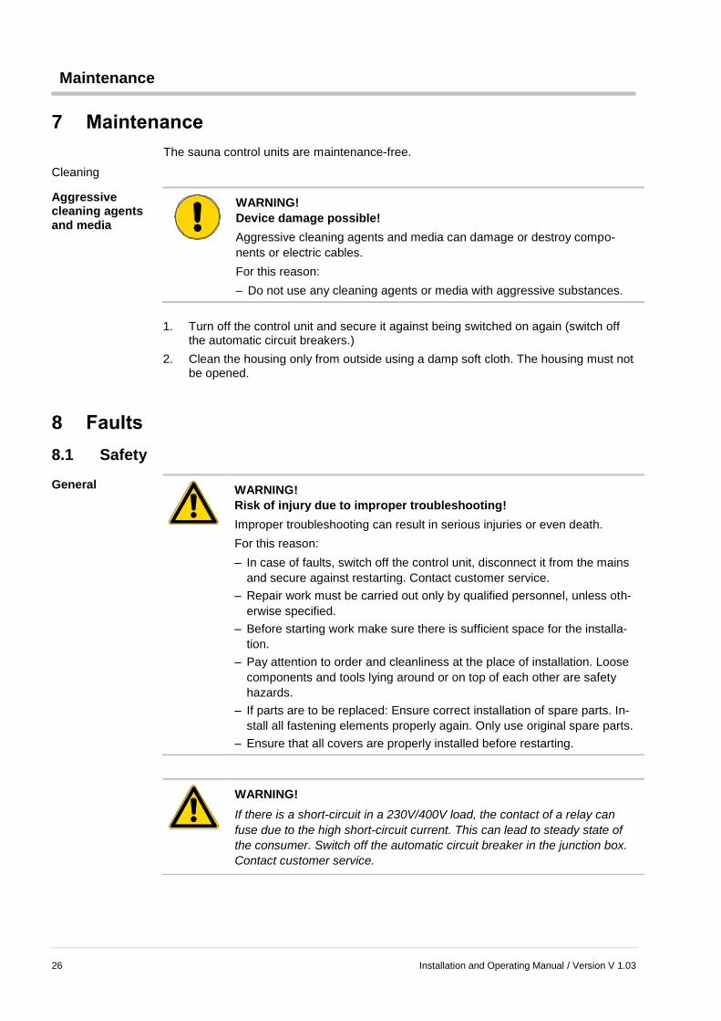
7 Maintenance
The sauna control units are maintenance-free.
Cleaning
Aggressive cleaning agents and media
WARNING!
Device damage possible!
Aggressive cleaning agents and media can damage or destroy compo-
nents or electric cables.
For this reason:
– Do not use any cleaning agents or media with aggressive substances.
1. Turn off the control unit and secure it against being switched on again (switch off the automatic circuit breakers.)
2. Clean the housing only from outside using a damp soft cloth. The housing must not be opened.
8 Faults
8.1 Safety
General
WARNING!
Risk of injury due to improper troubleshooting!
Improper troubleshooting can result in serious injuries or even death.
For this reason:
– In case of faults, switch off the control unit, disconnect it from the mains
and secure against restarting. Contact customer service.
– Repair work must be carried out only by qualified personnel, unless oth-
erwise specified.
– Before starting work make sure there is sufficient space for the installa-
tion.
– Pay attention to order and cleanliness at the place of installation. Loose
components and tools lying around or on top of each other are safety
hazards.
– If parts are to be replaced: Ensure correct installation of spare parts. In-
stall all fastening elements properly again. Only use original spare parts.
– Ensure that all covers are properly installed before restarting.
WARNING!
If there is a short-circuit in a 230V/400V load, the contact of a relay can
fuse due to the high short-circuit current. This can lead to steady state of
the consumer. Switch off the automatic circuit breaker in the junction box.
Contact customer service.
Faults
Installation and Operating Manual / Version V 1.03 27
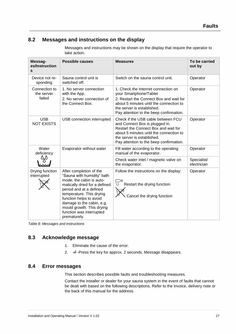
8.2 Messages and instructions on the display
Messages and instructions may be shown on the display that require the operator to
take action.
Messag-es/Instructions
Possible causes Measures To be carried out by
Device not re-sponding
Sauna control unit is switched off.
Switch on the sauna control unit. Operator
Connection to the server
failed
1. No server connection with the App.
2. No server connection of the Connect Box.
1. Check the Internet connection on your Smartphone/Tablet
2. Restart the Connect Box and wait for about 5 minutes until the connection to the server is established. Pay attention to the beep confirmation.
Operator
USB NOT EXISTS
USB connection interrupted Check if the USB cable between FCU and Connect Box is plugged in. Restart the Connect Box and wait for about 5 minutes until the connection to the server is established. Pay attention to the beep confirmation.
Operator
Water deficiency
Evaporator without water Fill water according to the operating manual of the evaporator.
Operator
Check water inlet / magnetic valve on the evaporator.
Specialist/ electrician
Drying function interrupted
After completion of the “Sauna with humidity” bath mode, the cabin is auto-matically dried for a defined period and at a defined temperature. This drying function helps to avoid damage to the cabin, e.g. mould growth. This drying function was interrupted prematurely.
Follow the instructions on the display:
Restart the drying function
Cancel the drying function
Operator
Table 8: Messages and instructions
8.3 Acknowledge message
1. Eliminate the cause of the error.
2. -Press the key for approx. 2 seconds. Message disappears.
8.4 Error messages
This section describes possible faults and troubleshooting measures.
Contact the installer or dealer for your sauna system in the event of faults that cannot
be dealt with based on the following descriptions. Refer to the invoice, delivery note or
the back of this manual for the address.
Faults
28 Installation and Operating Manual / Version V 1.03
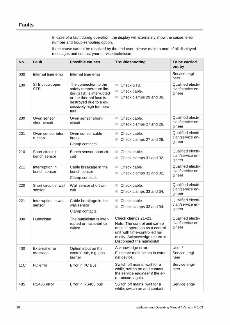
In case of a fault during operation, the display will alternately show the cause, error
number and troubleshooting option.
If the cause cannot be resolved by the end user, please make a note of all displayed
messages and contact your service technician.
No. Fault Possible causes Troubleshooting To be carried out by
000 Internal time error Internal time error Service engi-neer
100 STB circuit open, STB
The connection to the safety temperature lim-iter (STB) is interrupted or the thermal fuse is destroyed due to a ex-cessively high tempera-ture.
Check STB.
Check cable.
Check clamps 29 and 30.
Qualified electri-cian/service en-gineer
200 Oven sensor short-circuit
Oven sensor short-circuit
Check cable.
Check clamps 27 and 28.
Qualified electri-cian/service en-gineer
201 Oven sensor inter-ruption
Oven sensor cable break
Clamp contacts
Check cable.
Check clamps 27 and 28.
Qualified electri-cian/service en-gineer
210 Short circuit in bench sensor
Bench sensor short cir-cuit
Check cable.
Check clamps 31 and 32.
Qualified electri-cian/service en-gineer
211 Interruption in bench sensor
Cable breakage in the bench sensor
Clamp contacts
Check cable.
Check clamps 31 and 32.
Qualified electri-cian/service en-gineer
220 Short circuit in wall sensor
Wall sensor short cir-cuit
Check cable.
Check clamps 33 and 34.
Qualified electri-cian/service en-gineer
221 Interruption in wall sensor
Cable breakage in the wall sensor
Clamp contacts
Check cable.
Check clamps 33 and 34.
Qualified electri-cian/service en-gineer
300 Humidistat The humidistat is inter-rupted or has short cir-cuited
Check clamps 21–23.
Note: The control unit can re-main in operation as a control unit with time-controlled hu-midity. Acknowledge the error Disconnect the humidistat.
Qualified electri-cian/service en-gineer
400 External error message
Option input on the control unit, e.g. gas burner
Acknowledge error.
Eliminate malfunction in exter-nal device.
User /
Service engi-neer
11C I²C error Error in I²C Bus Switch off mains, wait for a while, switch on and contact the service engineer if the er-ror occurs again.
Service engi-neer
485 RS485 error Error in RS485 bus Switch off mains, wait for a while, switch on and contact
Service engi-

Decommissioning and disposal
Installation and Operating Manual / Version V 1.03 29
No. Fault Possible causes Troubleshooting To be carried out by
the service engineer if the er-ror occurs again.
neer
800 Drying did not end correctly.
Drying temperature was not reached, pro-gram cancellation by the user or error
Execute the drying program or acknowledge the error. Start the sauna program if the cabin is damp.
User
999 Internal time error Internal time error Service engi-neer
Table 9: Error messages
8.5 Acknowledge error message
1. Eliminate the cause of the error.
2. -Press the key for approx. 2 seconds. Message disappears.
9 Decommissioning and disposal
Do not dispose of the sauna control unit with regular garbage.
Dispose the control system in accordance with the respective country-specific
regulations.
10 General
10.1 Limitation on liability
All the specifications and directions in this manual have been prepared based on the
statutory standards and regulations, the present state of technology, as well as our
many years of knowledge and experience.
The manufacturer is not responsible for damage due to:
Non-adherence to the operating and installation instructions
Non-intended use
Unauthorised alterations
Technical changes
Use of own installation tools (only the provided installation tools are permitted)
Use of non-licensed spare and wear parts.
The actual delivery package can deviate from the given descriptions and illustrations in
case of special designs, additional orders or due to latest technical changes.

General
30 Installation and Operating Manual / Version V 1.03
Otherwise, the obligations agreed in the delivery contract, the General Terms and Con-
ditions as well as the delivery conditions of the manufacturer and the legal regulations
valid at the time of entering into the contract are applicable.
Warranty The warranty period of the manufacturer shall commence with the dispatch from the manufacturer’s place and is valid for 24 months. The dispatch date can be obtained from device number on the type plate.
The manufacturer is not responsible for any warranty claims deviating from this regula-tion. Warranty claims must be made to the manufacturer of the sauna system or the dealer.
10.2 Copyright protection
NOTE!
All data, texts, drawings, images and other illustrations are copyright pro-
tected and are subject to the commercial copyright laws. Any misuse is
punishable by law.
Distribution of any kind, even in parts, as well as reproduction and/or sharing the con-
tent without the prior written consent of the manufacturer is strictly prohibited.
10.3 Scope of delivery
See the enclosed delivery note for the scope of delivery.
10.4 Spare parts
CAUTION!
Risk of injury due to incorrect spare parts.
Wrong or defective spare parts can result in damage, malfunctions or total
failure as well as hamper safety.
For this reason:
– Only use original spare parts from the manufacturer.
– Repair work at the control unit must be carried out only by qualified per-
sonnel.
Order spare parts from the installer or the dealer of the sauna system. For address, see
invoice, delivery note or the back of this manual.
10.5 Customer service
For technical details, please contact your dealer or the installer of the sauna system.
For address, see invoice, delivery note or the back of this manual.

Settings
Installation and Operating Manual / Version V 1.03 31
NOTE!
For quick processing, have the data of the type plate such as the type, se-
ries number, variant etc. ready before making the call.
11 Settings
11.1 Adjusting range: sauna
min. max.
Temperature 10°C 110°C
Operating time 00:15 h 06:00 (20:00*)
11.2 Adjusting range: Sauna with humidity
min. max.
Temperature 10°C 65°C
Humidity 30% (01 F) 80% (09 F)
Operating time 00:15 h 06:00 (20:00*)
Drying temperature 80°C 110°C
Drying time 0 59 min.
Humidity – temp., sum according to VDE characteristic EN 60335 – 2 – 53:2003 + A1:2007 image 101
11.3 Adjusting range: Infrared
min. max.
Temperature 40°C 90°C (45°C **)
Base temperature -- 65°C (40°C **)
Operating time 00:15 h 06:00 (20:00*)
* The control units are delivered with a maximum adjustable heating period of 6 hours.
Please contact the installer or the dealer of your sauna system if you require a heating
period of more than 6 hours.
** The temperature can be restricted to 45 °C for Austria.

Declaration of Conformity
32 Installation and Operating Manual / Version V 1.03
12 Declaration of Conformity The electronics mounted in the device series FCU6xxx is identical to the certified device
series FCU4xxx.
You will find the current declaration of conformity online at www.fasel-gmbh.de in the
section “Wellness, Sauna and Spa control units” under “Service / Downloads”.

Declaration of Conformity
Installation and Operating Manual / Version V 1.03 33
Index
B
Bath mode
Setting ............................................................. 21
C
Cleaning.............................................................. 25
Cleaning light ...................................................... 17
Components ....................................................... 12
Connection ......................................................... 13
Control unit ......................................................... 12
Control unit ON / OFF ......................................... 17
Copyright protection ........................................... 30
Customer service ................................................ 30
D
Declaration of Conformity ................................... 31
Decommissioning ............................................... 29
Disposal .............................................................. 29
E
Electric voltage ..................................................... 8
Error messages .................................................. 29
Explanation of symbols ......................................... 5
F
Faults .................................................................. 26
Function .............................................................. 17
G
General ............................................................... 29
H
Hazard warnings ................................................... 7
I
Improper operation ............................................... 8
Initial operation ................................................... 13
Installing WEB-CONTROL-CONVER ................. 11
Intended use ......................................................... 6
Interface converter .............................................. 13
L
Limitation on liability ........................................... 29
M
Main switch ......................................................... 17
Mains adapter ..................................................... 13
Maintenance ....................................................... 25
Menu
Aroma .............................................................. 24
Basic settings: .................................................24
Coloured light ..................................................24
Info menu ........................................................25
Settings ...........................................................22
Timer ...............................................................23
Messages and instructions .................................26
Mode of operation ...............................................15
N
Notes
Operation.........................................................19
O
Occupational safety .............................................. 7
Operating keys ....................................................18
Basic functions ................................................18
Bath modes .....................................................18
Main switch......................................................17
Operation ............................................................19
P
Power off .............................................................17
R
Restart ................................................................15
S
Safety
Operation.........................................................19
Troubleshooting ..............................................26
Sauna control unit
switching off ....................................................21
switching on ....................................................20
Schematic connection .........................................10
Scope of delivery ................................................30
Settings ...............................................................31
Spare parts .........................................................30
Status bar............................................................18
Switching off................................................. 15, 21
Switching on ................................................ 20, 29
T
Technical data ....................................................16
U
USB cable ...........................................................13
W
Warnings ............................................................... 5
Warranty .............................................................30


Address of the installer or the dealer of the sauna sys-tem: