Embed Size (px)
Citation preview
Series and Parallel Networks
ET 162 Circuit Analysis
Electrical and Telecommunication Engineering Technology
Professor Jang

AcknowledgementAcknowledgement
I want to express my gratitude to Prentice Hall giving me the permission to use instructor’s material for developing this module. I would like to thank the Department of Electrical and Telecommunications Engineering Technology of NYCCT for giving me support to commence and complete this module. I hope this module is helpful to enhance our students’ academic performance.
OUTLINESOUTLINES
Introduction to Series-Parallel Networks Reduce and Return Approach
Block Diagram Approach
Descriptive Examples
Ladder Networks
ET162 Circuit Analysis – Series and Parallel Networks Boylestad 2
Key Words: Series-Parallel Network, Block Diagram, Ladder Network
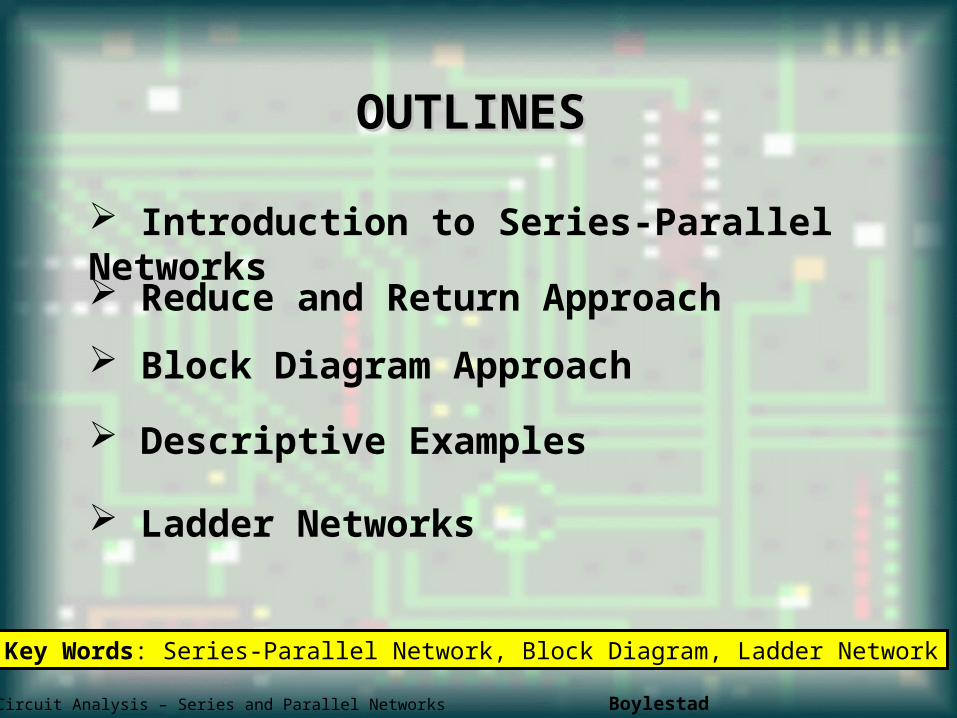
FIGURE 7.1 Introducing the reduce and return approach.
Series-Parallel Networks –Reduce and Return
Approach
Series-parallel networks are networks that contain both series and parallel circuit configurations
For many single-source, series-parallel networks, the analysis is one that works back to the source, determines the source current, and then finds its way to the desired unknown.
ET162 Circuit Analysis – Series and parallel networks Boylestad 3
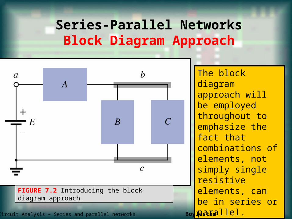
FIGURE 7.2 Introducing the block diagram approach.
Series-Parallel NetworksBlock Diagram Approach
The block diagram approach will be employed throughout to emphasize the fact that combinations of elements, not simply single resistive elements, can be in series or parallel.
ET162 Circuit Analysis – Series and parallel networks Boylestad 4
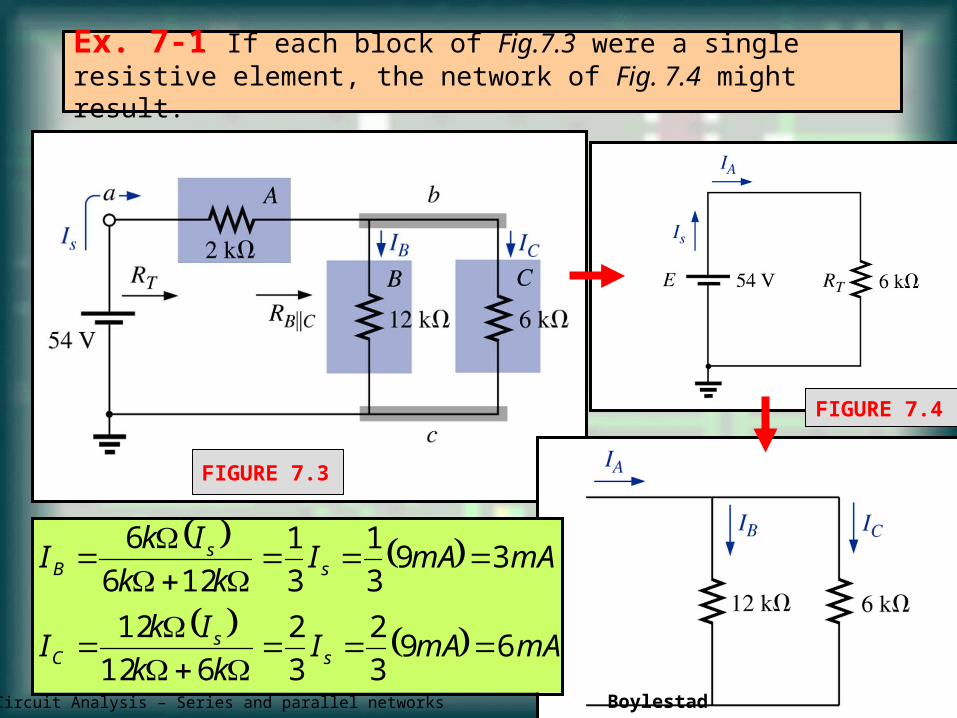
FIGURE 7.3
Ex. 7-1 If each block of Fig.7.3 were a single resistive element, the network of Fig. 7.4 might result.
mAmAIkk
IkI
mAmAIkk
IkI
ss
C
ss
B
693
2
3
2
612
12
393
1
3
1
126
6
FIGURE 7.4
ET162 Circuit Analysis – Series and parallel networks Boylestad 4
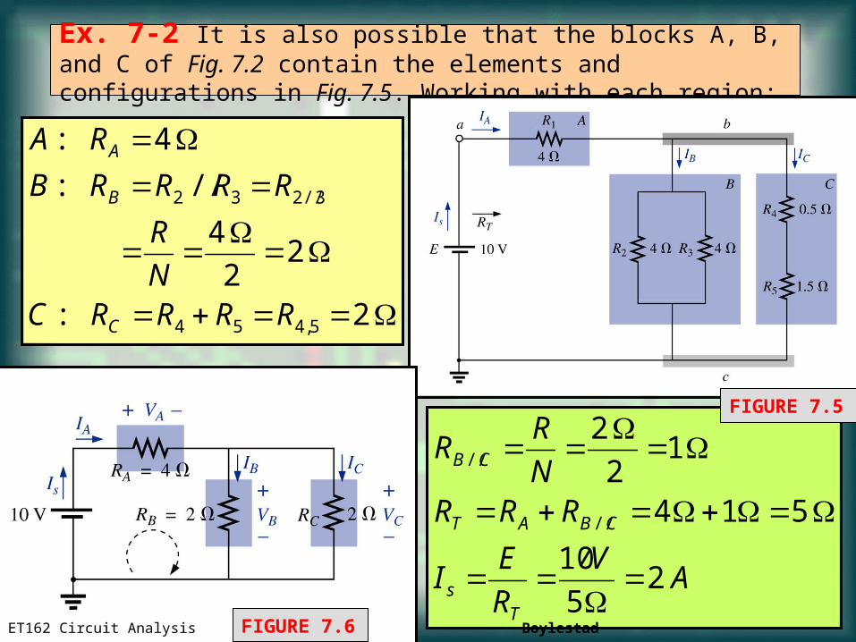
AV
R
EI
RRRN
RR
Ts
CBAT
CB
25
10
514
12
2
//
//
Ex. 7-2 It is also possible that the blocks A, B, and C of Fig. 7.2 contain the elements and configurations in Fig. 7.5. Working with each region:
2:
22
4
//:
4:
5,454
3//232
RRRRCN
R
RRRRB
RA
C
B
A
FIGURE 7.5
FIGURE 7.6ET162 Circuit Analysis Boylestad 6
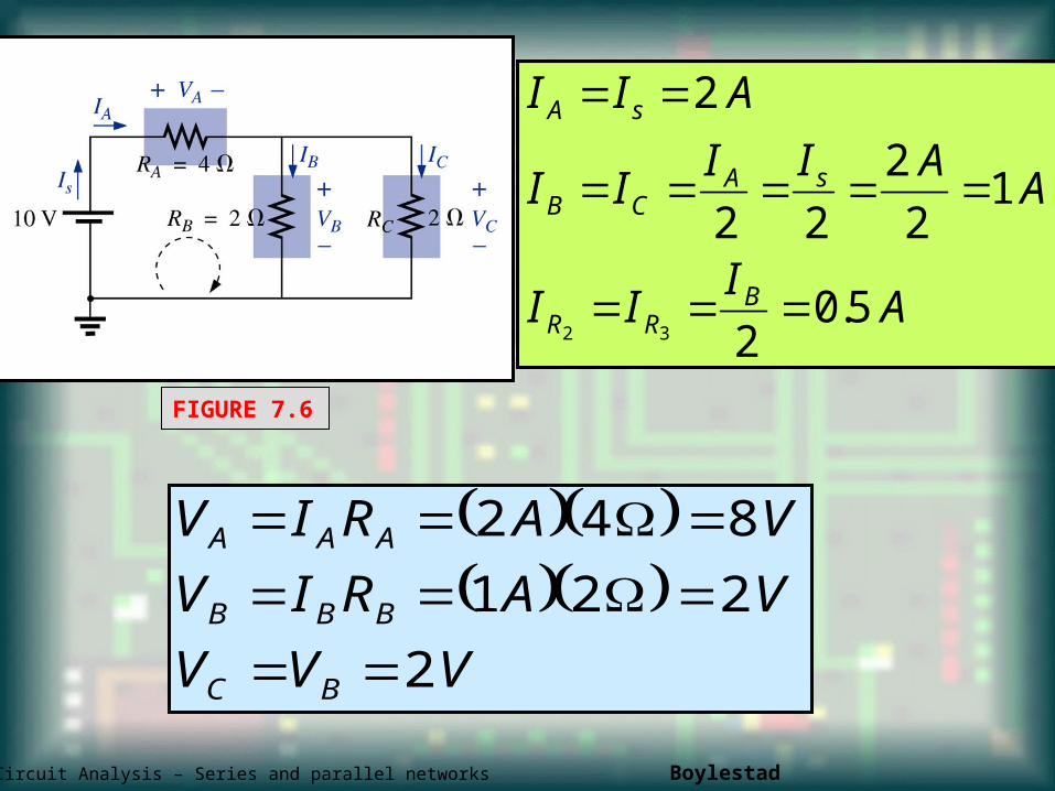
AI
II
AAII
II
AII
BRR
sACB
sA
5.02
12
2
22
2
32
VVV
VARIV
VARIV
BC
BBB
AAA
2
221
842
ET162 Circuit Analysis – Series and parallel networks Boylestad 7
FIGURE 7.6
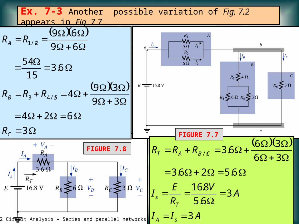
Ex. 7-3 Another possible variation of Fig. 7.2 appears in Fig. 7.7.
3
624
39
394
6.315
54
69
69
5//43
2//1
C
B
A
R
RRR
RR
AII
AV
R
EI
RRR
sA
Ts
CBAT
3
36.5
8.16
6.526.3
36
366.3//
FIGURE 7.7
FIGURE 7.8
ET162 Circuit Analysis – Series and parallel networks 8
VARIVRIV
VARIV
lawsOhmBy
AAAIII
lawcurrentsKirchhoffBy
AA
RR
IRI
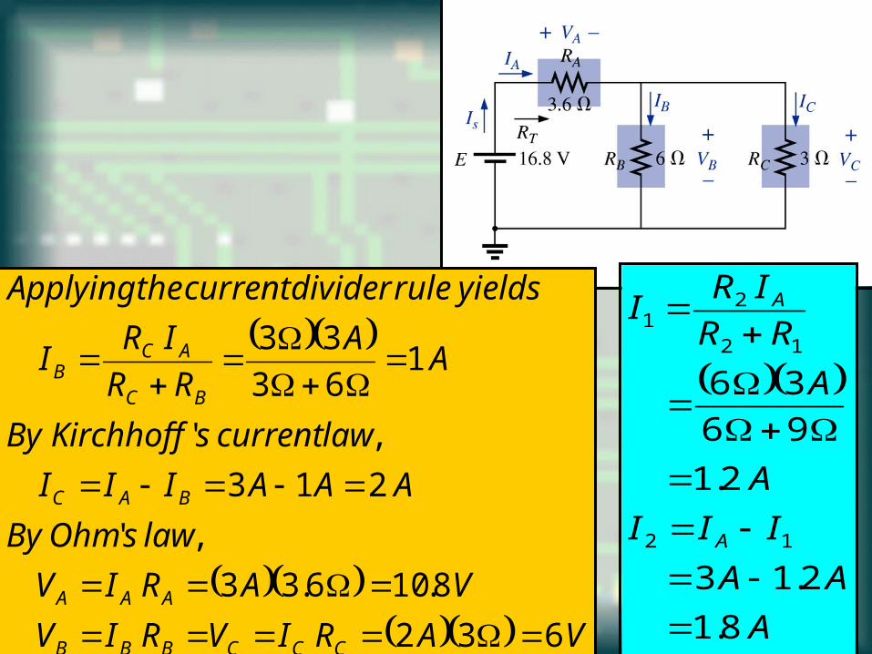
yieldsruledividercurrenttheApplying
CCCBBB
AAA
BAC
BC
ACB
632
8.106.33
,'
213
,'
163
33
A
AA
III
A
A
RR
IRI
A
A
8.1
2.13
2.1
96
36
12
12
21
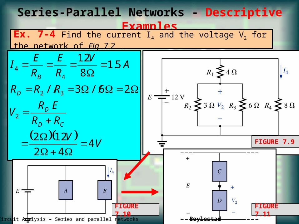
Series-Parallel Networks - Descriptive Examples
Ex. 7-4 Find the current I4 and the voltage V2 for the network of Fig. 7.2 .
V
V
RR
ERV
RRR
AV
R
E
R
EI
CD
D
D
B
442
122
26//3//
5.18
12
2
32
44
FIGURE 7.9
FIGURE 7.10 FIGURE 7.11ET162 Circuit Analysis – Series and parallel networks Boylestad 10
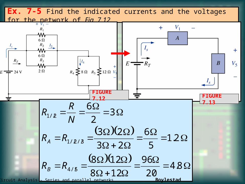
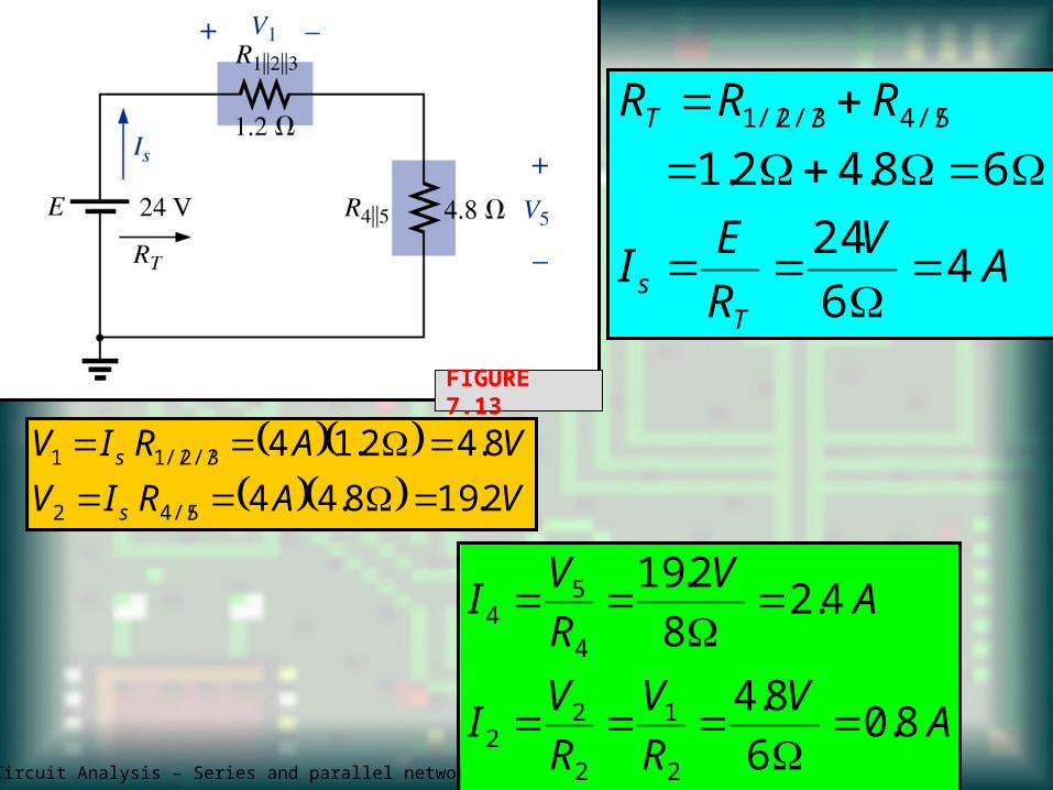
Ex. 7-5 Find the indicated currents and the voltages for the network of Fig. 7.12 .
FIGURE 7.13
8.420
96
128
128
2.15
6
23
23
32
6
5//4
3//2//1
2//1
RR
RR
N
RR
B
A
FIGURE 7.12
ET162 Circuit Analysis – Series and parallel networks Boylestad 11
ET162 Circuit Analysis – Series and parallel networks Boylestad 12
AV
R
EI
RRR
Ts
T
46
24
68.42.15//43//2//1
VARIV
VARIV
s
s
2.198.44
8.42.14
5//42
3//2//11
FIGURE 7.13
AV
R
V
R
VI
AV
R
VI
8.06
8.4
4.28
2.19
2
1
2
22
4
54
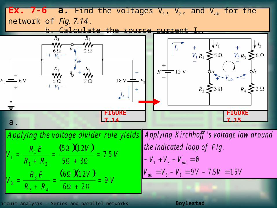
Ex. 7-6 a. Find the voltages V1, V2, and Vab for the network of Fig. 7.14. b. Calculate the source current Is.
A pplying the vo ltage d ivider ru le yields
VR E
R R
VV
VR E
R R
VV
11
1 2
33
3 4
5 1 2
5 37 5
6 1 2
6 29
.
A pplying K irchho ff s vo ltage law around
the ind ica ted loop o f F ig
V V V
V V V V V Vab
ab
'
.
. .
1 3
3 1
0
9 7 5 1 5
FIGURE 7.14a.
FIGURE 7.15
ET162 Circuit Analysis – Series and parallel networks Boylestad 13
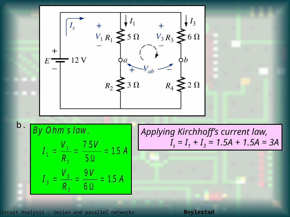
b.B y O hm s law
IV
R
VA
IV
R
VA
' ,
..
.
11
1
33
3
7 5
51 5
9
61 5
Applying Kirchhoff’s current law,Is = I1 + I3 = 1.5A + 1.5A = 3A
ET162 Circuit Analysis – Series and parallel networks Boylestad 14
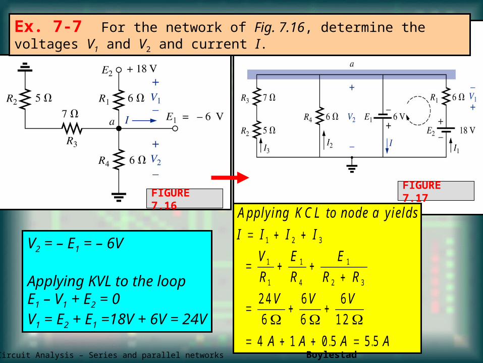
Ex. 7-7 For the network of Fig. 7.16, determine the voltages V1 and V2 and current I.
FIGURE 7.17FIGURE 7.16
V2 = – E1 = – 6V
Applying KVL to the loopE1 – V1 + E2 = 0V1 = E2 + E1 =18V + 6V = 24V
A pplying K C L to node a yields
I I I I
V
R
E
R
E
R R
V V V
A A A A
1 2 3
1
1
1
4
1
2 3
2 4
6
6
6
6
1 2
4 1 0 5 5 5
. .
ET162 Circuit Analysis – Series and parallel networks Boylestad 15
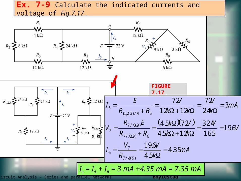
Ex. 7-9 Calculate the indicated currents and voltage of Fig.7.17.
FIGURE 7.17.
mAk
V
R
VI
VV
kk
Vk
RR
ERV
mAk
V
kk
V
RR
EI
35.45.4
6.19
6.195.16
324
125.4
725.4
324
72
1212
72
)9,8//(7
76
6)9,8//(7
)9,8//(77
54//)3,2,1(5
Is = I5 + I6 = 3 mA +4.35 mA = 7.35 mA
9 kΩ
ET162 Circuit Analysis – Series and parallel networks Boylestad 16
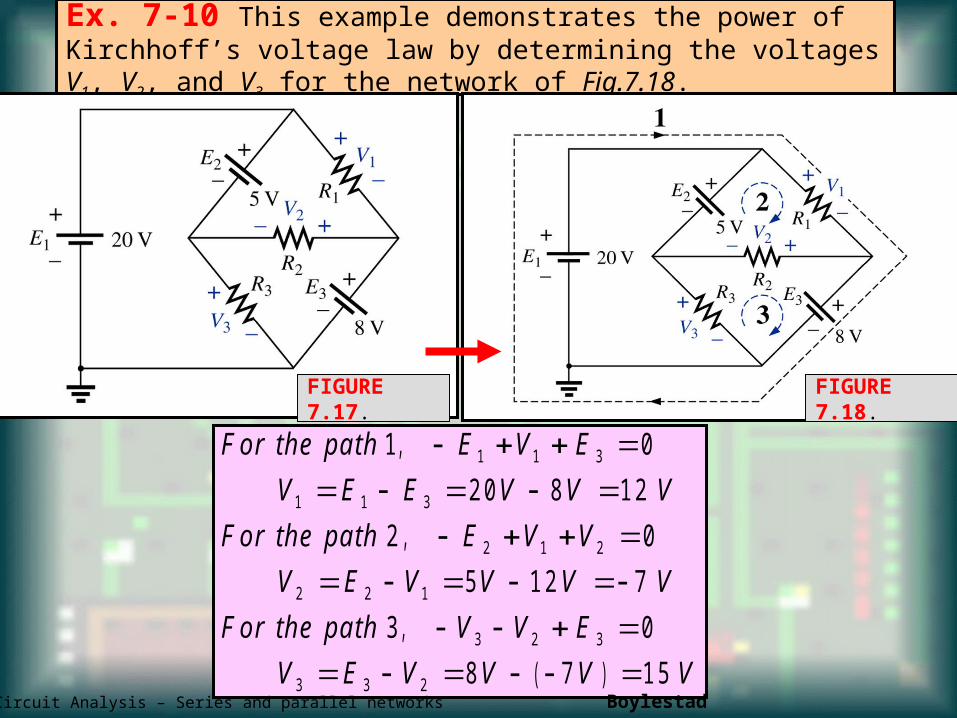
Ex. 7-10 This example demonstrates the power of Kirchhoff’s voltage law by determining the voltages V1, V2, and V3 for the network of Fig.7.18.
FIGURE 7.17.
F or the pa th E V E
V E E V V V
F or the pa th E V V
V E V V V V
F or the pa th V V E
V E V V V V
1 0
2 0 8 1 2
2 0
5 1 2 7
3 0
8 7 1 5
1 1 3
1 1 3
2 1 2
2 2 1
3 2 3
3 3 2
,
,
,
( )
FIGURE 7.18.
ET162 Circuit Analysis – Series and parallel networks Boylestad 17
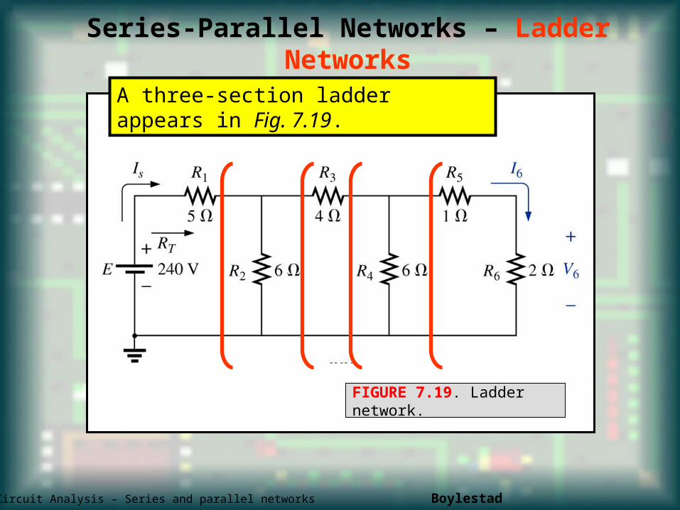
Series-Parallel Networks – Ladder Networks
A three-section ladder appears in Fig. 7.19.
FIGURE 7.19. Ladder network.
ET162 Circuit Analysis – Series and parallel networks Boylestad 18
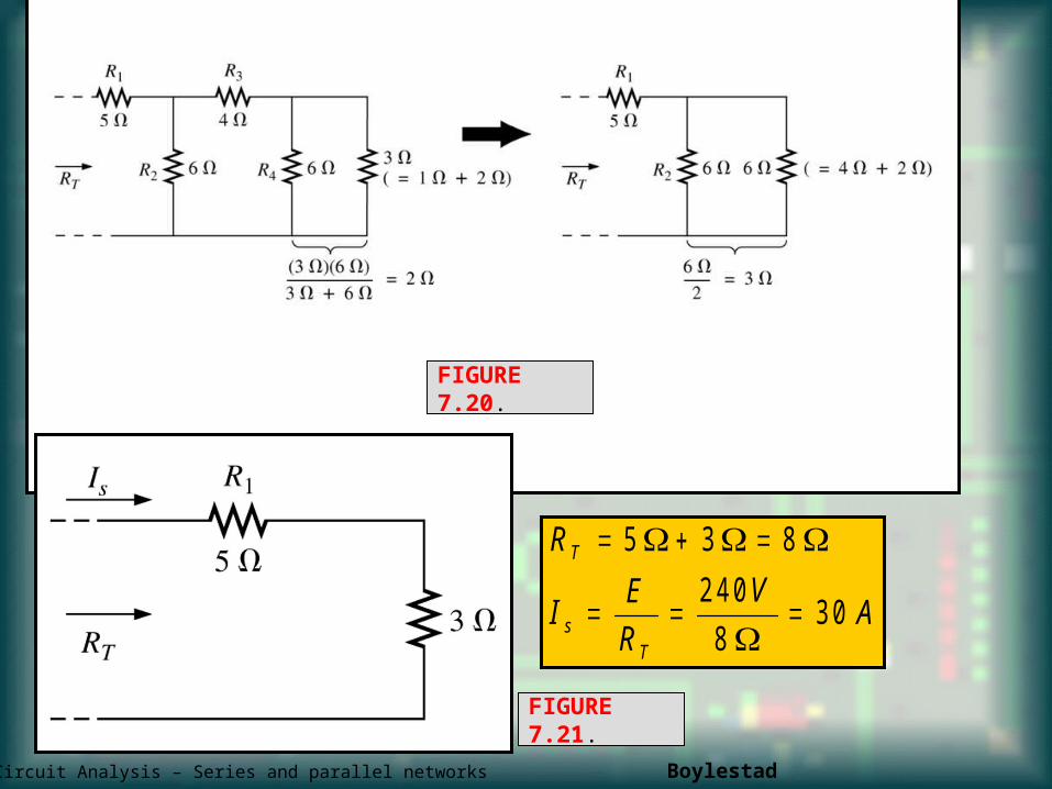
R
IE
R
VA
T
sT
5 3 8
2 4 0
83 0
FIGURE 7.20.
FIGURE 7.21.
ET162 Circuit Analysis – Series and parallel networks Boylestad 19
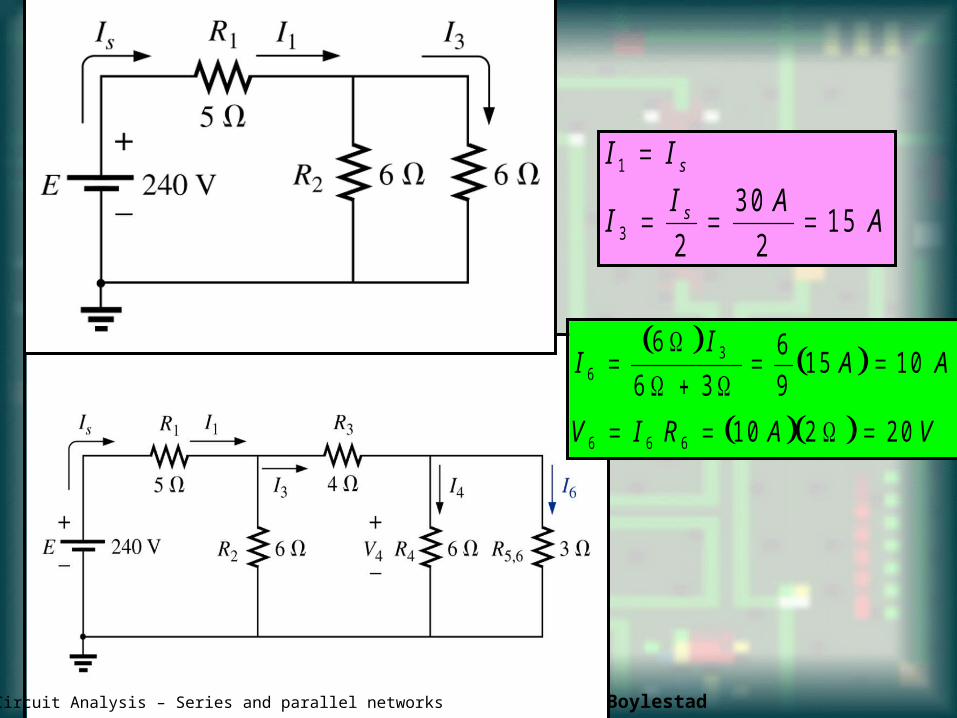
I I
II A
A
s
s
1
3 2
3 0
21 5
II
A A
V I R A V
63
6 6 6
6
6 3
6
91 5 1 0
1 0 2 2 0
ET162 Circuit Analysis – Series and parallel networks Boylestad 20


![Reading Skill [Jang]](https://img.pdfslide.us/doc/110x75/5561a892d8b42afd708b4fa2/reading-skill-jang.jpg)