Embed Size (px)
Citation preview

Water Conditioning Control System
Dealer Installation, Operation and Maintenance Manual
Series 255 Valve / 960 Control

2
Table of Contents
Introduction . . . . . . . . . . . . . . . . . . . . . . . . . . . 3
Installation . . . . . . . . . . . . . . . . . . . . . . . . . . . . 5Location SelectionWater Line ConnectionDrain Line ConnectionBrine Line ConnectionBrine Tank Overflow Connection
Placing Conditioner into Operation . . . . . . . . . 6Initial Start-UpConnecting the Control
Programming the Model 960 Control . . . . . . . 7Level I ParametersLevel II ParametersSpecial Notes for Level II ParametersRefill Control Valve
Regeneration . . . . . . . . . . . . . . . . . . . . . . . . . 12Manual RegenerationAutomatic Regeneration
Service . . . . . . . . . . . . . . . . . . . . . . . . . . . . . 14Removing the Control
Preventive Maintenance . . . . . . . . . . . . . . . . 15Injector Screen and InjectorWater Meter
Disinfection of Water Conditioners . . . . . . . . 16Sodium Hypochlorite 5.25%Calcium Hypochlorite
Specifications. . . . . . . . . . . . . . . . . . . . . . . . . 17
Pressure Graphs. . . . . . . . . . . . . . . . . . . . . . . 18
Control Valving Identification . . . . . . . . . . . . . 19
Valve Disc Operation . . . . . . . . . . . . . . . . . . . 19
Flow Diagrams . . . . . . . . . . . . . . . . . . . . . . . . 19
Replacement Parts. . . . . . . . . . . . . . . . . . . . . 21
Splicing the Low Voltage Transformer Cord. . 24
Troubleshooting . . . . . . . . . . . . . . . . . . . . . . . 25AlarmsTroubleshooting Procedures
IMPORTANT:
The plug-in transformer for this equipment is rated for indoor use only.
IMPORTANT:
Never attempt to work on this control while standing in or near water without disconnecting electrical power to the control.
3
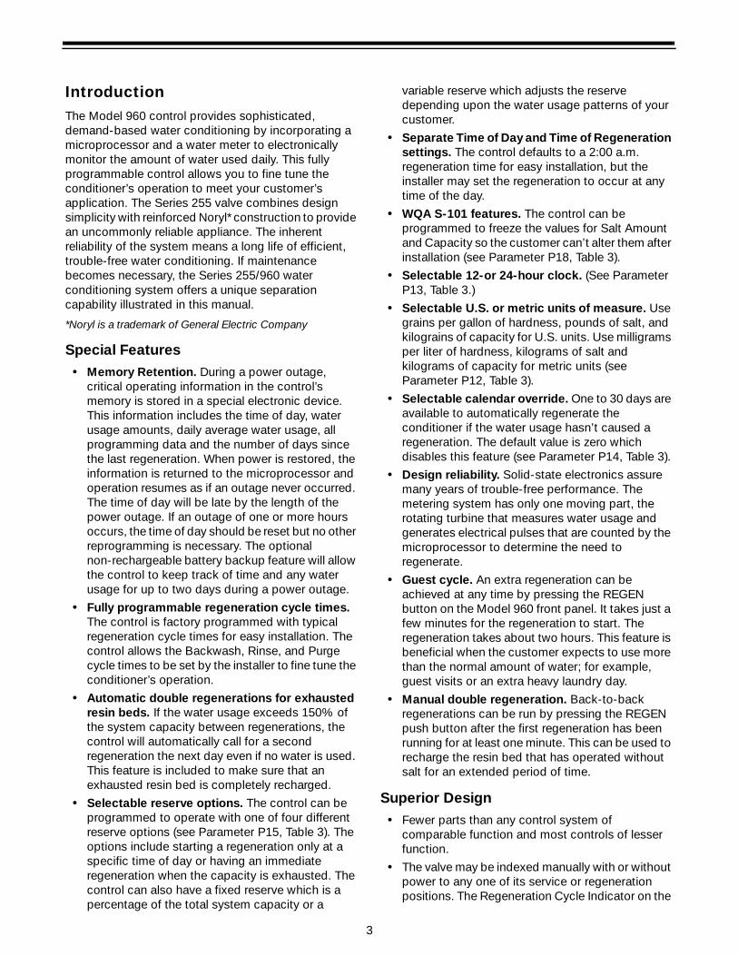
IntroductionThe Model 960 control provides sophisticated, demand-based water conditioning by incorporating a microprocessor and a water meter to electronically monitor the amount of water used daily. This fully programmable control allows you to fine tune the conditioner’s operation to meet your customer’s application. The Series 255 valve combines design simplicity with reinforced Noryl* construction to provide an uncommonly reliable appliance. The inherent reliability of the system means a long life of efficient, trouble-free water conditioning. If maintenance becomes necessary, the Series 255/960 water conditioning system offers a unique separation capability illustrated in this manual.
*Noryl is a trademark of General Electric Company
Special Features• Memory Retention. During a power outage,
critical operating information in the control’s memory is stored in a special electronic device. This information includes the time of day, water usage amounts, daily average water usage, all programming data and the number of days since the last regeneration. When power is restored, the information is returned to the microprocessor and operation resumes as if an outage never occurred. The time of day will be late by the length of the power outage. If an outage of one or more hours occurs, the time of day should be reset but no other reprogramming is necessary. The optional non-rechargeable battery backup feature will allow the control to keep track of time and any water usage for up to two days during a power outage.
• Fully programmable regeneration cycle times. The control is factory programmed with typical regeneration cycle times for easy installation. The control allows the Backwash, Rinse, and Purge cycle times to be set by the installer to fine tune the conditioner’s operation.
• Automatic double regenerations for exhausted resin beds. If the water usage exceeds 150% of the system capacity between regenerations, the control will automatically call for a second regeneration the next day even if no water is used. This feature is included to make sure that an exhausted resin bed is completely recharged.
• Selectable reserve options. The control can be programmed to operate with one of four different reserve options (see Parameter P15, Table 3). The options include starting a regeneration only at a specific time of day or having an immediate regeneration when the capacity is exhausted. The control can also have a fixed reserve which is a percentage of the total system capacity or a
variable reserve which adjusts the reserve depending upon the water usage patterns of your customer.
• Separate Time of Day and Time of Regeneration settings. The control defaults to a 2:00 a.m. regeneration time for easy installation, but the installer may set the regeneration to occur at any time of the day.
• WQA S-101 features. The control can be programmed to freeze the values for Salt Amount and Capacity so the customer can’t alter them after installation (see Parameter P18, Table 3).
• Selectable 12-or 24-hour clock. (See Parameter P13, Table 3.)
• Selectable U.S. or metric units of measure. Use grains per gallon of hardness, pounds of salt, and kilograins of capacity for U.S. units. Use milligrams per liter of hardness, kilograms of salt and kilograms of capacity for metric units (see Parameter P12, Table 3).
• Selectable calendar override. One to 30 days are available to automatically regenerate the conditioner if the water usage hasn’t caused a regeneration. The default value is zero which disables this feature (see Parameter P14, Table 3).
• Design reliability. Solid-state electronics assure many years of trouble-free performance. The metering system has only one moving part, the rotating turbine that measures water usage and generates electrical pulses that are counted by the microprocessor to determine the need to regenerate.
• Guest cycle. An extra regeneration can be achieved at any time by pressing the REGEN button on the Model 960 front panel. It takes just a few minutes for the regeneration to start. The regeneration takes about two hours. This feature is beneficial when the customer expects to use more than the normal amount of water; for example, guest visits or an extra heavy laundry day.
• Manual double regeneration. Back-to-back regenerations can be run by pressing the REGEN push button after the first regeneration has been running for at least one minute. This can be used to recharge the resin bed that has operated without salt for an extended period of time.
Superior Design• Fewer parts than any control system of
comparable function and most controls of lesser function.
• The valve may be indexed manually with or without power to any one of its service or regeneration positions. The Regeneration Cycle Indicator on the

4
control face plate indicates control valve position.
• No dynamic seals that could cause leakage through wear or fatigue.
• Control accepts Noryl brass manifold or modular bypass valve without modification, offering complete versatility and easy plumbing for any installation.
• Brining control valve built into system eliminates need for an external brine valve.
• Drain flow control is built into the valve to control backwash and fast rinse flow rates.
Superior Operation• Direct acting system functions independently of
water pressure. No pistons or diaphragms that
require a minimum water pressure to operate.
• Five-cycle operation provides for downflow conditioned water, upflow backwash, downflow brining and slow rinse, downflow fast rinse, and refill of the brine tank.
• Valve discs are held closed by water pressure and are leak tight. Valve seats are in a vertical position, which is the position least vulnerable to plugging.
• System operation cannot get out of phase or sequence. The control always returns to a fixed conditioned water position after regeneration.
• Bypass water is automatically available during regeneration.
Figure 1 - Control
Figure 2 - Tank Adapter
Brine Line Fitting Connection 1/4-inch NPTAir Check
Tank Thread 2-1/2-inch - 8 Male NPSM
Inlet Connection 3/4-inch or 1-inch NPT or BSPT
Drain Connection 3/8-inch or 1/2-inch NPT or BSPT
Outlet Connection 3/4-inch or 1-inch NPT or BSPT
Optional Bypass

5
InstallationAll plumbing must conform to local codes. Inspect the unit carefully for carrier shortage or shipping damage.
Location SelectionThe following considerations must be taken into account when selecting the location for the water conditioning system.
• Locate the system as close to a drain as possible.
• If supplementary water treating equipment is required, make sure that adequate additional space is available. Locate the brine tank in an accessible place so that salt can be easily added.
• Do not install any unit closer than 10 feet (3 m) of piping between the outlet of the conditioner and the inlet of a water heater. Water heaters can transmit heat back down the cold water pipe into the control valve. Hot water can severely damage the conditioner.
A 10-foot (3-m) total pipe run (including bends, elbows, etc.) is a reasonable distance to prevent hot water damage. A positive way to prevent hot water from flowing from a heat source to the conditioner is to install a check valve in the soft water piping from the conditioner. If a check valve is installed, make sure that the water heating unit is equipped with a properly rated temperature and pressure safety relief valve. Always conform to local codes.
• Do not locate the unit in an area where the temperature ever falls below 34oF (1oC) or over 120oF (49oC).
• Do not install the unit near acid or acid fumes.
• Do not expose the unit to petroleum products.
Water Line ConnectionA bypass valve system must be installed since there are occasions when the water conditioner must be bypassed for hard water or for servicing. The most common bypass systems are the Autotrol® Series 256 bypass valve, Figure 3, and plumbed-in globe valves, Figure 4. Though both are similar in function, the Autotrol bypass offers simplicity and ease of operation.
Figure 3
Figure 4
Drain Line ConnectionIdeally located, the unit will be above and not more than 20 feet (6.1 m) from the drain. For such installations connect an appropriate fitting and 1/2-inch (1.3-cm) plastic tubing to the drain line connection on the rear of the control valve.
Figure 5
If the unit is located more than 20 feet (6.1 m) from the drain, use 3/4-inch (1.9-cm) tubing for runs up to 40 feet (12.2 m). Also, purchase appropriate fitting to connect the 3/4-inch tubing to the 1/2-inch NPT drain connection.
If the unit is located where the drain line must be elevated, you may elevate the line up to 6 feet (1.8 m) providing the run does not exceed 15 feet (4.6 m) and
Not in Bypass In Bypass
Water Conditioner
Water Conditioner

6
water pressure at the conditioner is not less than 40 psi (2.8 bar). You may elevate an additional 2 feet (61 cm) for each additional 10 psi (0.7 bar).
Where drain line is elevated but empties into a drain below the level of the control valve, form a 7-inch (18-cm) loop at the far end of the line so that the bottom of the loop is level with the drain line connection. This will provide an adequate siphon trap (Figure 5).
Where a drain empties into an overhead sewer line, a sink-type trap must be used.
IMPORTANT: Never connect the drain line into a drain, sewer line, or trap. Always allow an air gap between the drain line and the wastewater to prevent the possibility of sewage being back-siphoned into the conditioner.
Note: Standard commercial practices have been expressed here. Local codes may require changes to these suggestions.
Brine Line ConnectionInstall an appropriate fitting onto the 1/4-inch male NPT connection on the air check, Figure 7, and install a length of flexible tubing between the air check fitting and the brine pickup tube at the brine tank.
Note: Make sure that all fittings and connections are vacuum tight so that premature checking does not take place. Premature checking occurs when the ball in the air check falls to the bottom before all brine is drawn out of the brine tank. Refer to the Troubleshooting section in this manual for additional information.
Brine Tank Overflow Line ConnectionIn the event of a malfunction, the brine tank overflow connection directs overflow to the drain instead of spilling it on the floor where it could cause water damage. Complete the following steps to connect the overflow fitting to the brine tank:
1. Locate the fitting hole on the side of the brine tank.
2. Insert the overflow fitting (not supplied) into the tank and tighten with the plastic thumb nut and gasket as illustrated in Figure 6.
3. Attach a length of 1/2-inch (1.3-cm) tubing (not supplied) to the fitting and run to the drain.
Figure 6 - Overflow Line Connection
Note: Do not elevate the overflow line higher than 3 inches (7.6 cm) below the bottom of the overflow fitting. Do not tie into the drain line of the control unit. The overflow line must be a direct, separate line from the overflow fitting to the drain, sewer, or tub. Allow an air gap as in the drain line connection, Figure 5.
Placing Conditioner into Operation
Initial Start-UpAfter the water conditioning system is installed, the conditioners should be disinfected before they are used to treat potable water. Refer to the Disinfection of Water Conditioners section in this manual. Complete the following steps to place the conditioner into operation:
1. Remove the rear valve cover by pulling back on the tab located on the lower rear edge of the cover. Next, lift the cover off the valve, Figure 10.
2. Grasp the camshaft and rotate it COUNTERCLOCKWISE (as viewed from the front of the control) until the indicator on the regeneration cycle indicator points directly to the word BACKWASH.
3. Fill the mineral tank with water. Turn the water supply off and place the bypass valve(s) into the “not in bypass” position. Open the water supply valve very slowly to approximately the 1/4 open position.
IMPORTANT: If the water supply valve is opened too rapidly or too far, resin may be lost. In the BACKWASH position, you should hear air escaping slowly from the drain line.
4. When all of the air is purged from the tank (water begins to flow steadily from the drain), slowly open the main supply valve all the way. Allow the water to run into the drain until clear. Turn off the water supply and wait for about five minutes to allow all trapped air to escape from the tank.
Brine Tank Overflow FittingInstalled
Connect 1/2-in. (13 cm)I.D. Tubing or Hose and Runto Drain
7
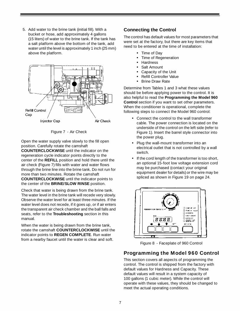
5. Add water to the brine tank (initial fill). With a bucket or hose, add approximately 4 gallons (15 liters) of water to the brine tank. If the tank has a salt platform above the bottom of the tank, add water until the level is approximately 1 inch (25 mm) above the platform.
Figure 7 - Air Check
Open the water supply valve slowly to the fill open position. Carefully rotate the camshaft COUNTERCLOCKWISE until the indicator on the regeneration cycle indicator points directly to the center of the REFILL position and hold there until the air check (Figure 7) fills with water and water flows through the brine line into the brine tank. Do not run for more than two minutes. Rotate the camshaft COUNTERCLOCKWISE until the indicator points to the center of the BRINE/SLOW RINSE position.
Check that water is being drawn from the brine tank. The water level in the brine tank will recede very slowly. Observe the water level for at least three minutes. If the water level does not recede, if it goes up, or if air enters the transparent air check chamber and the ball falls and seats, refer to the Troubleshooting section in this manual.
When the water is being drawn from the brine tank, rotate the camshaft COUNTERCLOCKWISE until the indicator points to REGEN COMPLETE. Run water from a nearby faucet until the water is clear and soft.
Connecting the ControlThe control has default values for most parameters that were set at the factory, but there are key items that need to be entered at the time of installation:
• Time of Day• Time of Regeneration• Hardness• Salt Amount• Capacity of the Unit• Refill Controller Value• Brine Draw Rate
Determine from Tables 1 and 3 what these values should be before applying power to the control. It is also helpful to read the Programming the Model 960 Control section if you want to set other parameters. When the conditioner is operational, complete the following steps to connect the Model 960 control:
• Connect the control to the wall transformer cable. The power connection is located on the underside of the control on the left side (refer to Figure 1). Insert the barrel style connector into the power plug.
• Plug the wall-mount transformer into an electrical outlet that is not controlled by a wall switch.
• If the cord length of the transformer is too short, an optional 15-foot low voltage extension cord may be purchased (contact your original equipment dealer for details) or the wire may be spliced as shown in Figure 19 on page 24.
Figure 8 - Faceplate of 960 Control
Programming the Model 960 ControlThis section covers all aspects of programming the control. The control is shipped from the factory with default values for Hardness and Capacity. These default values will result in a system capacity of 100 gallons (1 cubic meter). While the control will operate with these values, they should be changed to meet the actual operating conditions.

8
Note that some parameters have a single unit of measure option such as the Rinse Time which is only entered in minutes. Other parameters have dual units such as Salt Amount which can be entered in pounds or kilograms. To select which units are active, look for a comment in the NOTES column of Tables 1 and 3. It will reference another parameter that selects which units are active. For example, Parameter P12 (Table 3) selects U.S. units if it is set to “0” and metric if it is set to “1.”
Level I Parameters (Table 1)Level I Parameters are identified as those that have an LED indicator on the front panel. The green indicator illuminates next to the name of the active control setting. The end user has access to all of these parameters which are explained in the Series 960 Operation and Maintenance Manual, R-360 (P/N 1017934). In general, pressing the down arrow (↓) button displays the Level I Parameters in the following order:
• Time of Day• Time of Regeneration• Hardness• Salt Amount • Capacity
If you continue to press the down arrow (↓) button, the parameters start over with Time of Day. Pressing the up arrow (↑) button displays the parameters in reverse order. Refer to Table 1 for a description of these parameters and the available ranges for each parameter.
Press the SET button and the far right number on the display starts flashing. If you want to change this number, press the up arrow (↑) button to increase the number or the down arrow (↓) button to decrease the number. To skip the number without changing, press the left arrow (←) button. When you reach the far left digit, pressing the left arrow (←) button will return you to the far right digit.
Note: If you press and hold either the up arrow (↑) button or the down arrow (↓) button for more than one second, the flashing number will increment or decrement at the rate of 10 counts per second.
When the number is correct, press the left arrow (←) button. The first number stops flashing and the next number starts flashing. You can only change the flashing number. Continue changing numbers until you reach the desired setting. Press the SET button. The numbers stop flashing and the control accepts the new setting. After approximately 30 seconds, the control starts alternating the display between Time of Day and Capacity.
Note: If a beep sounds, the new setting is not accepted because it was outside the allowable range. The old value will be displayed.
Time of DayPress the SET button. The display will show the Time of Day with the minutes digit blinking. If you want to change this number, press the up arrow (↑) button to increase the number or the down arrow (↓) button to decrease the number. To skip the number without changing, press the left arrow (←) button. The first number stops flashing and the next number starts flashing. You can only change the flashing number. When you have reached the far left digit, pressing the left arrow (←) button returns you to the far right digit. Continue changing numbers until you reach the desired setting. Press the SET button to enter the value.
Time of RegenerationThe next value displayed is the Time of Regeneration. It has a default value of 2:00 a.m. If this is not acceptable, press the SET button and change the number. Press the SET button to enter the value. If 2:00 a.m. is acceptable, press the down arrow (↓) button.
HardnessHardness is the next value displayed. This value is the water hardness expressed in grains per gallon (milligrams per liter). The default value is 10 grains/gallon (100 mg/L). If this is not acceptable, press the SET button and enter a new value. Any value between 3 and 250 grains per gallon (30 and 2500 milligrams per liter) is allowed. Press the SET button to enter the new value.
Salt AmountSalt Amount is the next value displayed. The default value for Salt Amount is 6 pounds (2.5 kilograms) of salt; refer to Table 2.
Note: This is the total amount of salt for a regeneration, not pounds per cubic foot. If 6 pounds is not acceptable, press the SET button and change the numbers. If 6 pounds is acceptable, press the down arrow (↓) button.
CapacityCapacity is the next value displayed and is expressed in kilograins (kilograms). Refer to Table 2 for the capacity setting that corresponds to the resin bed volume and salt amount. The default value is 1.0 kilograin (0.1 kilogram). If this is not acceptable, press the SET button and enter a new value. Any value between 0.1 and 140 kilograins (.01 and 14.00 kilograms) is allowed.

9
Note: If the calculation for the system capacity exceeds 9999 gallons (99.99 cubic meters) (P5, Capacity, divided by P3, Hardness,) the control will display 9999 (99.99) for capacity until the water usage has dropped the remaining capacity below that number. When water is flowing through the system, the colon in the Time of Day display will blink.
At this time, all of the mandatory parameters are filled and the control is ready for operation. The display will alternate between the Time of Day and Capacity if no keys are pressed for 30 seconds. The Capacity value is
the volume remaining in gallons (cubic meters for metric) before a regeneration is needed.
Verify proper power outage operation by briefly removing power to the control. The unit will beep and show the time of day when power is turned on.
If you wish to fine-tune the operation of this control, refer to Table 3 for details concerning allowable values, defaults, and parameter descriptions. The programming procedure is the same for all of these parameters.
Table 1 - Programming Parameters
Parameter Range of Values
Minimum Increments
Default Units of Measure
NotesName Description
P1Time of dayAM or PM
1:00 to 12:5900:00 to 23:59
1 None Hour:minuteRange depends on value
selected for P13. Enter the current time.
P2Time of day
of regeneration
1:00 to 12:59AM or PM
00:00 to 23:591 2:00 AM Hour:minute
Range depends on value selected for P13. Skip this parameter to accept the
default or enter a new time.
P3Hardness of
water3 to 250
30 to 25001
1010
100Grains/gallon
mg/L
Unit of measure depends on value selected for P12. Test water hardness and enter
that value.
P4 Salt amount0.5 to 99.50.1 to 25.5
0.50.1
62.5
PoundsKilograms
Unit of measure and default depends on value selected for P12. Refer to Table 2.
P5Capacity of
unit0.1 to 140.0
0.01 to 14.000.1
0.011.00.1
KilograinsKilograms
Unit of measure depends on value selected for P12. Enter
the unit capacity.
Table 2 - Suggested Salt Settings
(Pounds of Salt for Various Size Conditioners)
Resin Bed VolumeKilograins of
Hardness Capacity Setting
0.5 ft3 0.75 ft3 1.0 ft3 1.25 ft3 1.5 ft3 1.75 ft3 2.0 ft3
12 4.5 - - - - - -16 9.0 5.0 - - - - -20 - 8.5 6.0 - - - -24 - 14.0 8.5 7.0 - - -30 - - 15.0 11.0 9.0 - -32 - - 18.5 12.5 10.0 9.0 -35 - - - 16.0 12.0 10.0 9.040 - - - 23.0 17.0 14.0 12.048 - - - - 28.0 21.0 17.0

10
Level II Parameters (Table 3)
The Level II Parameters are P6 through P19 in Table 3. The Operation and Maintenance Manual for this product does not mention these parameters, so the end user does not normally have access to these values. To access Level II Parameters, simultaneously press and hold the down arrow (↓) and up arrow (↑) buttons for three seconds.
If the control was alternating between Time of Day and Capacity when the above button sequence is entered, the display shows P1. If a different Level I Parameter was displayed, the display shows the “P” number for that parameter. Refer to Table 3 to find the “P” number associated with each parameter. Use the up arrow (↑) button or the down arrow (↓) button to move from one parameter to the next. The display cycles through the “P” numbers shown in Tables 1 and 3. When you reach P19, the next P number will go back to P1.
When the parameter number you want to change is on the display, press the left arrow (←) button to display the data assigned to that parameter. Press the SET button and the far right number on the display starts flashing. If you want to change this number, press the up arrow (↑) button or the down arrow (↓) button. To skip the number without changing, press the left arrow (←) button. When the number is correct, press the SET button. The numbers stop flashing and the control accepts the new setting. If a beep sounds, the new setting was not accepted. Refer to Table 3 for allowable values for that parameter.
To change or view other parameters, press the left arrow (←) button to have the display show “P” numbers. Now use the up arrow (↑) button or the down arrow (↓) button to move to the parameter number you wish to change.
To exit the Level II programming mode, simultaneously press and hold the down arrow (↓) and up arrow (↑) buttons for three seconds, or wait 30 seconds without pressing a button. The control starts alternating the display between Time of Day and Capacity.
Settings for all parameters can be written on the label provided with the control. The label has an adhesive backing so it can be attached to the inside rear cover for future service reference.
Special Notes for Level II ParametersThe programming parameters in Level II can be used to increase the efficiency of this conditioner. Especially note the Refill Controller and Brine Draw Value parameters. These were set at the factory to meet the needs of a system with low water pressure. If an installation has higher water pressure, uses a large injector, or does not use the default refill control value, the efficiency of the system can be improved by changing P6 and P7.
Refill Control ValueTo operate correctly, the timer must have Parameter P6 set to the correct value. The correct value is molded into the end of the refill controller as shown in Figure 9 which has the number 33. The default value in P6 is 33. If the value in P6 is larger than the number on the refill control, not enough brine will be made. If the value in P6 is smaller than the correct value, too much brine will be made. If 33 is not acceptable, press the SET button and enter a new value.
Figure 9 - Refill Control

11
Table 3 - Programming Parameters
Parameter
Name DescriptionRange of
ValuesMinimum
IncrementsDefault
Units of Measure
Notes
P6Refill
controller1 to 99 1 33
Enter the value molded into the end of the refill controller.
P7Brine draw
value1 to 99 1 25
Select number from Table 4 and enter that number.
P8 Not used NA NA NA NA NA
P9Backwash
time3 to 30 1 14 Minutes
Skip this parameter to accept the default or enter a value.
P10Slow rinse
time8 to 125 1 40 Minutes
Skip this parameter to accept the default or enter a value.
P11Fast rinse
time2 to 19 1 4 Minutes
Skip this parameter to accept the default or enter a value.
P12Units of
Mmeasure0 to 1 1 0
0 = U.S., 1 = Metric. Skip this parameter to accept U.S. or
enter 1 for Metric.
P13 Clock mode 0 to 1 1 0
0 = 12-hour clock. 1 = 24-hour clock. Skip this
parameter for a 12-hour clock or enter 1 for a 24-hour clock.
P14Calendar override
0 to 30 1 0 Days0 = no calendar override. Skip this parameter for no calendar
override or enter a value.
P15 Reserve type 0 to 3 1 0
0 = variable reserve, 1 = fixed reserve, 2 = variable reserve
with immediate regen, 3 = fixed reserve with
immediate regen. Skip this parameter to accept the
default or enter a different reserve type.
P16
Fixed reserve capacity or
initial average value
0 to 70 1 30Percent of capacity
Description depends on the value entered for P15. Skip
this parameter to accept the default or enter a different
value.
P17Operation
type0 to 1 1 0
0 = 5-cycle counter or co-current conditioner, 1 = reserved for future use.
P18Salt/capacity
change Lockout
0 to 1 1 0
0 = none, 1 = salt/capacity change locked out. Skip this
parameter to accept the default or enter 1 to lock out
salt/capacity change.
P19Factory defaults
0 to 3 1 9
Loads in a set of default values. Refer to the Special
Notes for Level II Parameters section in this
manual.

12
Brine Draw Value
Parameter P7 is used by the control to calculate the brine draw time. The default value of 25 was selected for a “B” injector with low water pressure or an “A” injector with moderate water pressure. If this does not match your installation, press the SET button and enter a new value. Refer to Table 4 for the correct value. Find the injector used in the 255 valve. The injector cap is labeled with the injector letter and the injector is color coded for easy identification. Next, determine the typical water pressure for this installation. The Brine Draw Value is an estimate of the flow rate of brine through the injector. This rate varies with water pressure and injector type as shown in Table 4. The control calculates the brine draw time using this value and the salt amount. The brine draw time is added to the Rinse Time (P10) to determine the total Brine Draw/Slow Rinse Time.
• This control does not use Parameter P8. No entry is needed for this parameter.
• Parameter P12 selects the units of measure. Be sure that this is set to the correct value before entering any data for Parameters P3, P4 or P5.
• Parameter P13 selects the clock display mode. If the 12-hour mode is selected, a PM indicator is used. If the 24-hour mode is selected, the PM indicator is not used.
• Parameter P15 has four allowable values. Values 0 or 1 will cause the control to wait for Parameter P2, time of day of regeneration, to begin the regeneration. Values 2 or 3 will cause the control to start the regeneration as soon as the capacity is exhausted.
• When Parameter P15 selects a variable reserve type, 0 or 2, Parameter P16 is used to calculate the initial seven average daily water usage values. The control multiplies the total capacity by the percentage entered for Parameter P16 and uses that value as the initial average daily usage for each day of the week until water usage establishes new averages.
• Parameter 17 has two allowable values, 0 or 1, however, the 1 is reserved for future options and thus should not be used. Improper regenerations will occur if P17 is set to 1.
• Parameter P18 allows the installer to lock the Salt Amount and Capacity values so they cannot be changed. When Parameter 18 is set to 1, those two settings can only be viewed when the control is in the Level II mode. The settings will be skipped when the control is in the Level I mode. When Parameter 18 is set to zero, the Salt Amount and Capacity can be viewed and changed in either Level I or Level II.
• Parameter P19 is used at the factory to enter default values. This parameter does not need to be changed. Using this parameter will erase the values for all other parameters and replace them with default values. Improper regenerations will occur if P19 is set to a 1 or 3.
RegenerationWhen the control begins a regeneration, the display will alternate between Time of Day and Regen Time Remaining. The Regen Time Remaining is shown in minutes. The control will start and stop an internal motor which drives the camshaft through the various regeneration positions. The control uses the information entered in the parameters shown in Table 3 to determine how long each part of the cycle should last. The control will stop the camshaft at the correct location for each part of the regeneration cycle.
If power fails during a regeneration cycle, the cycle completes normally when the power is restored.
Note: The REGEN button is only active when the display is alternating between Time of Day and Capacity. When programming Level I or II parameters, the REGEN button is not active.
Conditioned water is available when the control enters the brine refill cycle. The Regen Time Remaining in regeneration will continue to count down until the indicator points to REGENERATION COMPLETE.
Manual RegenerationTo force the control to perform a regeneration, press the REGEN button. This button is located on the front of the control. When you press the REGEN button, the control performs a full regeneration of the conditioner.
If you press this button again more than one minute after regeneration begins, but before the regeneration is complete, a second regeneration will start when the first regeneration is finished. The display will freeze and only show the Regen Time Remaining as an indication that the second regeneration will be performed. When the first regeneration is complete, the second one will begin and the display will alternate between Time of Day and Regen Time Remaining.
Table 4 - Brine Draw Value
Injector Color
Brine Draw
Value at 30 psi
Brine Draw
Value at 50 psi
Brine Draw
Value at 70 psi
A White 19 26 31B Blue 24 30 37C Red 29 37 40

13
Automatic RegenerationThere are two ways to have the control automatically start a regeneration: calendar override or having the control monitor the water usage.
Calendar override
This feature is set in Parameter P14. It can be set for one to 30 days. If it is set to zero, this feature is disabled. When this feature is active, the control keeps track of the number of days since the last regeneration and when that number equals the value set in P14, a regeneration is automatically started at the Time of Regeneration set in P2.
Control monitors the water usage
The control compares the water usage to the calculated volume capacity of the system. The control uses the Capacity Parameter P5 divided by the Hardness Parameter P3 to calculate the volume capacity of the system. It also uses a reserve value to determine if a regeneration is necessary. If the water usage since the last regeneration is greater than the system capacity minus the reserve, a regeneration is needed.
Note: If the water usage exceeds 150% of the system capacity between regenerations, the control will automatically call for a second regeneration the next day even if no water is used. This feature is included to make sure that an exhausted resin bed is completely recharged.
Reserve optionsThere are two types of reserve options for this control: fixed reserve and historical water usage pattern. They are selected with Parameter P15.
Fixed reserve
When the fixed reserve is selected, the control multiplies the maximum system capacity by the percent value set in Parameter P16 and uses the result as a reserve.
Water usage pattern
The other reserve option allows the control to adjust the reserve based upon the historical water usage pattern of the system. The control keeps track of the water usage for each day of the week and uses that day’s average usage multiplied by 1.2 as the reserve for that day. Every day at the Time of Regeneration, the control recalculates the day’s average water usage. If less than 10% of a day’s average water usage is used, the control will not change the day’s average. If more than twice the day’s average is used, the control uses the actual usage in the reserve calculation.
Since a new installation has no history of water usage, the control multiplies the percent of capacity value set in Parameter P16 by the total system capacity to determine starting average for each day of the week. The factory set default value for P16 is 30 which means that 30% of the total system capacity is used for the starting average for each day.
Program Parameter P15 is also used to select whether the control waits until the Time of Regeneration set in Parameter P2 to start a regeneration, or if the control should begin a regeneration immediately when the capacity remaining is less than the reserve.

14
Service
Removing the ControlComplete the following steps to remove the control module for servicing:
1. Unplug the wall-mount transformer.
2. Shut off the water supply or put the bypass valve(s) into bypass position.
3. Remove the rear cover by pushing back on the tab provided on the cover, Figure 10. Next, lift the rear cover off the valve.
Figure 10
4. Relieve system pressure by opening the backwash drain valve (the sixth valve back from the control) with a screwdriver, Figure 11.
Figure 11
5. To remove the camshaft or reinstall it, the rib on the shaft must be pointing straight up. This occurs when the indicator knob is rotated to the refill position. Press down on the back of the camshaft to disengage it from the rear “hoop” of the top plate, Figure 12.
Slide the camshaft back to disengage it from the timer, Figure 13.
Figure 12
Figure 13
6. Disconnect the turbine probe from the turbine assembly.
7. Lift the control off the valve, Figure 14. To replace the control, reverse the above procedure. Note that the camshaft needs to be positioned correctly before it can be inserted into the back of the control. There is a locating rib on the camshaft. Position the rib on the top of the shaft and slide the camshaft into the control. Push up on the end of the camshaft, furthest from the timer, snapping it into place.
Figure 14
Inlet
OutletDrain
15
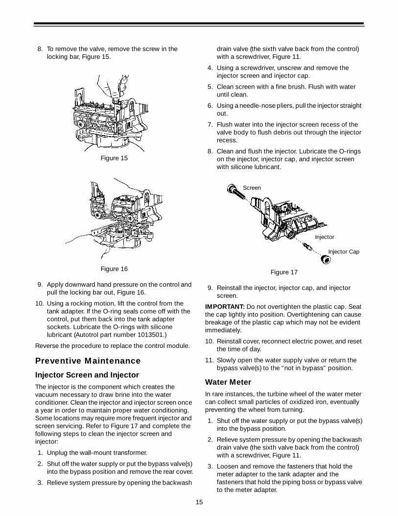
8. To remove the valve, remove the screw in the locking bar, Figure 15.
Figure 15
Figure 16
9. Apply downward hand pressure on the control and pull the locking bar out, Figure 16.
10. Using a rocking motion, lift the control from the tank adapter. If the O-ring seals come off with the control, put them back into the tank adapter sockets. Lubricate the O-rings with silicone lubricant (Autotrol part number 1013501.)
Reverse the procedure to replace the control module.
Preventive Maintenance
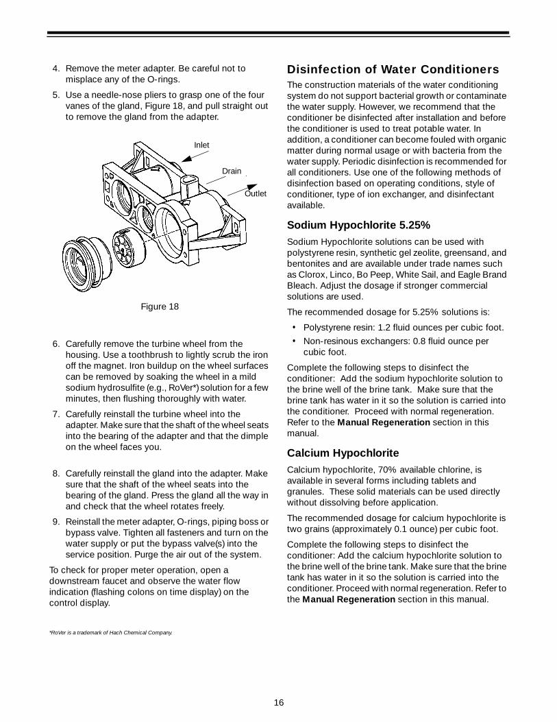
Injector Screen and InjectorThe injector is the component which creates the vacuum necessary to draw brine into the water conditioner. Clean the injector and injector screen once a year in order to maintain proper water conditioning. Some locations may require more frequent injector and screen servicing. Refer to Figure 17 and complete the following steps to clean the injector screen and injector:
1. Unplug the wall-mount transformer.
2. Shut off the water supply or put the bypass valve(s) into the bypass position and remove the rear cover.
3. Relieve system pressure by opening the backwash
drain valve (the sixth valve back from the control) with a screwdriver, Figure 11.
4. Using a screwdriver, unscrew and remove the injector screen and injector cap.
5. Clean screen with a fine brush. Flush with water until clean.
6. Using a needle-nose pliers, pull the injector straight out.
7. Flush water into the injector screen recess of the valve body to flush debris out through the injector recess.
8. Clean and flush the injector. Lubricate the O-rings on the injector, injector cap, and injector screen with silicone lubricant.
Figure 17
9. Reinstall the injector, injector cap, and injector screen.
IMPORTANT: Do not overtighten the plastic cap. Seat the cap lightly into position. Overtightening can cause breakage of the plastic cap which may not be evident immediately.
10. Reinstall cover, reconnect electric power, and reset the time of day.
11. Slowly open the water supply valve or return the bypass valve(s) to the “not in bypass” position.
Water MeterIn rare instances, the turbine wheel of the water meter can collect small particles of oxidized iron, eventually preventing the wheel from turning.
1. Shut off the water supply or put the bypass valve(s) into the bypass position.
2. Relieve system pressure by opening the backwash drain valve (the sixth valve back from the control) with a screwdriver, Figure 11.
3. Loosen and remove the fasteners that hold the meter adapter to the tank adapter and the fasteners that hold the piping boss or bypass valve to the meter adapter.
Injector
Injector Cap
Screen
16
4. Remove the meter adapter. Be careful not to misplace any of the O-rings.
5. Use a needle-nose pliers to grasp one of the four vanes of the gland, Figure 18, and pull straight out to remove the gland from the adapter.
Figure 18
6. Carefully remove the turbine wheel from the housing. Use a toothbrush to lightly scrub the iron off the magnet. Iron buildup on the wheel surfaces can be removed by soaking the wheel in a mild sodium hydrosulfite (e.g., RoVer*) solution for a few minutes, then flushing thoroughly with water.
7. Carefully reinstall the turbine wheel into the adapter. Make sure that the shaft of the wheel seats into the bearing of the adapter and that the dimple on the wheel faces you.
8. Carefully reinstall the gland into the adapter. Make sure that the shaft of the wheel seats into the bearing of the gland. Press the gland all the way in and check that the wheel rotates freely.
9. Reinstall the meter adapter, O-rings, piping boss or bypass valve. Tighten all fasteners and turn on the water supply or put the bypass valve(s) into the service position. Purge the air out of the system.
To check for proper meter operation, open a downstream faucet and observe the water flow indication (flashing colons on time display) on the control display.
*RoVer is a trademark of Hach Chemical Company.
Disinfection of Water ConditionersThe construction materials of the water conditioning system do not support bacterial growth or contaminate the water supply. However, we recommend that the conditioner be disinfected after installation and before the conditioner is used to treat potable water. In addition, a conditioner can become fouled with organic matter during normal usage or with bacteria from the water supply. Periodic disinfection is recommended for all conditioners. Use one of the following methods of disinfection based on operating conditions, style of conditioner, type of ion exchanger, and disinfectant available.
Sodium Hypochlorite 5.25%Sodium Hypochlorite solutions can be used with polystyrene resin, synthetic gel zeolite, greensand, and bentonites and are available under trade names such as Clorox, Linco, Bo Peep, White Sail, and Eagle Brand Bleach. Adjust the dosage if stronger commercial solutions are used.
The recommended dosage for 5.25% solutions is:
• Polystyrene resin: 1.2 fluid ounces per cubic foot.
• Non-resinous exchangers: 0.8 fluid ounce per cubic foot.
Complete the following steps to disinfect the conditioner: Add the sodium hypochlorite solution to the brine well of the brine tank. Make sure that the brine tank has water in it so the solution is carried into the conditioner. Proceed with normal regeneration. Refer to the Manual Regeneration section in this manual.
Calcium HypochloriteCalcium hypochlorite, 70% available chlorine, is available in several forms including tablets and granules. These solid materials can be used directly without dissolving before application.
The recommended dosage for calcium hypochlorite is two grains (approximately 0.1 ounce) per cubic foot.
Complete the following steps to disinfect the conditioner: Add the calcium hypochlorite solution to the brine well of the brine tank. Make sure that the brine tank has water in it so the solution is carried into the conditioner. Proceed with normal regeneration. Refer to the Manual Regeneration section in this manual.
Inlet
Outlet
Drain

17
Specifications
255 Valve with 960 Control
Hydrostatic Test Pressure . . . . . . . . . . . . . . . . . . . . . . . . . . . . . . . . . . . . . . . . . . . . . . . . . . . . . . . . 300 psi (20.69 bar)Working Pressure. . . . . . . . . . . . . . . . . . . . . . . . . . . . . . . . . . 20 to 127 psi (1.38 to 8.76 bar), 100 psi max in CanadaVoltage. . . . . . . . . . . . . . . . . . . . . . . . . . . . . . . . . . . . . . . . . . . . . . . . . . . . . . . . . . . . . . . . . . . . 102 to 132 VAC 60 HzCurrent. . . . . . . . . . . . . . . . . . . . . . . . . . . . . . . . . . . . . . . . . . . . . . . . . . . . . . . . . . . . . . . . . . . . . . . . . . . . . . . . . 50 mAOperating Temperature . . . . . . . . . . . . . . . . . . . . . . . . . . . . . . . . . . . . . . . . . . . . . . . . . . . . . 34o to 120oF (1o to 18oC)Humidity . . . . . . . . . . . . . . . . . . . . . . . . . . . . . . . . . . . . . . . . . . . . . . . . . . . . . . . . . . 10 to 100% condensing allowedTransformer . . . . . . . . . . . . . . . . . . . . . . . . . . . . . . . . . . . . . . Wall mount with plug options, rated for indoor use onlyWater Flows. . . . . . . . . . . . . . . . . . . . . . . . . . . . . . . . . . . . . . . Accurate over range of 0.5 to 23 gpm (1.9 to 87 L/pm)Pressure Tank Thread . . . . . . . . . . . . . . . . . . . . . . . . . . . . . . . . . . . . . . . . . . . . . . . . . . . . . . . . . . . 2-1/2 inch - 8 maleBrine Line Thread . . . . . . . . . . . . . . . . . . . . . . . . . . . . . . . . . . . . . . . . . . . . . . . . . . . . . . . . . . . . . . 1/4-inch NPT maleDistributor Tube Diameter Required . . . . . . . . . . . . . . . . . . . . . . . . . . . . . . . . . . . . . . . . . . 13/16-inch (20.6-mm) ODDistributor Tube Length . . . . . . . . . . . . . . . . . . . . . . . . . . . . . . . 1-1/4-inch (31.8-mm) higher than top of mineral tankStandard Manifold Connection . . . . . . . . . . . . . . . . . . . . . . . . . . . . . . . 3/4-inch NPT inlet-outlet, 3/8-inch NPT drainOptional Manifold Connections. . . .1-inch NPT inlet-outlet, 1/2-inch NPT drain; 3/4-inch BSPT inlet-outlet, 3/8-inch. . . . . . . . . . . . . . . . . . . . . . . . . . . . . . . . . . . . . . . . . . . . . .BSPT drain; 1-inch BSPT inlet-outlet, 1/2-inch BSPT drainOptional Bypass Valve. . . . . . . . .3/4-inch (19.1-mm) or 1-inch (25.4-mm) copper tailpiece, 1/2-inch NPT male drainValve Module, Tank Adapter, Optional Bypass Valve . . . . . . . . . . . . . . . . . . . . . . . . . . . . . . . . . . . . .Reinforced NorylInlet-Outlet Manifold . . . . . . . . . . . . . . . . . . . . . . . . . . . . . . . . . . . . . . . . . . . . . . . . . . . . . . . Brass or reinforced NorylRubber Parts . . . . . . . . . . . . . . . . . . . . . . . . . . . . . . . . . . . . . . . . . . . . . . . . . . . . Compounded for cold water serviceInjector Size “A” White . . . . . . . . . . . . . Nozzle 0.042-inch (1.1-mm) diameter, Throat 0.089-inch (2.3-mm) diameterInjector Size “B” Blue . . . . . . . . . . . . . . Nozzle 0.052-inch (1.3-mm) diameter, Throat 0.099-inch (2.5-mm) diameterInjector Size “C” Red. . . . . . . . . . . . . . . Nozzle 0.059-inch (1.5-mm) diameter, Throat 0.099-inch (2.5-mm) diameterBackwash Controllers Available for 6-, 7-, 8-, 9-, 10-, 12- inch (15.2-, 17.8-, 20.3-, 22.9-,
25.4-, 30.5-cm) dia. mineral tanksAll are sized to flow 4.5 gpm/sq ft (183 L/min/m2) of bed area.
255 Valve with 960 Timer
Inlet
Outlet
Drain
13-11/16 inch (347 mm)
6-3/8 inch (162 mm)7-5/16 inch (185 mm)
1-1/4 inch (32 mm)
7-1
5/16
inch
(201
mm
)
4-1/16 inch (103 mm)4-5/8 inch (117 mm)
1-1/2-inch (38 mm)
1-1/2-inch (38 mm)
1 inch (25 mm)

18
Pressure Graphs
Tested with 3/4-inch Brass Manifold
Bar
BarBar

19
Control Valving Identification
Flow Diagrams
Brine (1)Inlet (2)
Bypass (4)Outlet (3)
Rinse Drain (5)
Backwash/Drain (6)
Valve Disc Operation

20


22
Valve Body and Tank Adapter Module
*Not Shown
Code
Part
No. Description Qty. Code
Part
No. Description Qty.1 1000238 Valve Assembly w/o Flow Controls 1 9 Injector Cap with O-Ring 1
2 1000824 Camshaft, Standard, One-Piece 1 1000217 “A” Cap
3 1000827 Valve Cover, Black 1 1000218 “B” Cap
4 Brine Refill Flow Control Assembly: 1 1000219 “C” Cap
1000221 .14 GPM 10 1033784 Tank Adapter Assembly 1
1000222 .33 GPM 11 1032416 Air Check Kit
1000223 .40 GPM 12 1010429 O-Ring, 3-1/8 x 3-1/2 x 3/16 BN 1
5 1000226 Screen/Cap Assembly with O-Ring 1 13 1010428 O-Ring, 3/4 x 1 x 1/8 EP 1
6 Drain Control Assembly with O-Rings: 1 14 1031402 Locking Bar: English Language 1
1034162 No. 6 for 6-inch Diameter Tank 15 1006093 Screw, No. 8 x 9/16 inch 1
1000209 No. 7 for 7-inch Diameter Tank 16 1001580 Spring, Valve Discs 9
1000210 No. 8 for 8-inch Diameter Tank Kits:
1000211 No. 9 for 9-inch Diameter Tank 17 1033066 New to Old Air Check Adapter
1000212 No. 10 for 10-inch Diameter Tank 18 1001404 O-Ring Group: Tank Adapter 1
1000213 No. 12 for 12-inch Diameter Tank 19 1040459 O-Ring Group: Piping Boss 1
20 1041010 13/16 Rubber Insert (Optional)
7 1030502 Ball, Flow Control 1 * 1000250 Valve Discs Replacement
8 Injector Assembly with O-Rings: 1
1032970 “A” Injector – White
1032971 “B” Injector – Blue
1032972 “C” Injector – Red

23
Meter Adapter, Bypass Valve, Piping Boss, and Wall-Mount Transformer
Inlet
Outlet
Drain
Bypass
Piping Boss
Meter Adapter 960 Control
Wall-Mount Transformer
Inlet
Outlet
Drain
1
2
1
2
12
4
3Inlet
Note: Do not use pipe joint compoundwhen threading pipe into the Noryl pipingboss. Use only Teflon* pipe tape. Do notovertighten pipe into Noryl piping boss.
*Teflon is a registered trademark of E.I. DuPont de Nemours andCompany, Inc.

24
Splicing the Low Voltage Transformer Cord1. Strip insulation from wire 5/16 inch (8 mm) from wire
end.
2. Insert stripped wire into barrel of connector and crimp. For best results, crimp twice per wire as shown in Figure 19.
Splice connectors or extension wire is not supplied. They are available at hardware or electrical stores.
Figure 19
CodePartNo. Description Qty. Code
PartNo. Description Qty.
1 1040769 Bypass Assembly 1 1 Kit Piping Boss (includes hardware): 1
2 1040524 Bypass Install Kit 1 1040277 3/4-inch NPT, Brass
* Tube and Pipe Adapters 1040278 1-inch NPT, Brass
1001606 3/4-inch Copper Tube Adapter Kit 1 1040281 3/4-inch BSPT, Brass
1001670 1-inch Copper Tube Adapter Kit 1 1040282 1-inch BSPT, Brass
1001608 22-mm Copper Tube Adapter Kit 1 1040279 3/4-inch NPT, Noryl
1001609 28-mm Copper Tu be Adapter Kit 1 1040280 1-inch NPT, Noryl
1001613 3/4-inch CPVC Tube Adapter Kit 1 1040283 3/4-inch BSPT, Noryl
1001614 1-inch CPVC Tube Adapter Kit 1 1040284 1-inch BSPT, Noryl
1001615 25-mm CPVC Tube Adapter Kit 1 2 1040339 Piping Boss Install Kit 1
1001769 3/4-inch NPT Plastic Pipe Adapter Kit 1
1001603 1-inch NPT Plastic Pipe Adapter Kit 1
1001604 3/4-inch BSPT Plastic Pipe Adapter Kit 1
1001605 1-inch BSPT Plastic Pipe Adapter Kit 1 3 960 Electronic Timer 1
1001611 3/4-inch BSPT Brass Pipe Adapter Kit 1
1001610 1-inch NPT Brass Pipe Adapter Kit 1
1001612 1-inch BSPT Brass Pipe Adapter Kit 1
4 Wall-Mount Transformer 1
1000810 100V Japanese Plug
1000811 120V North American Plug
1 1032350 Kit, Meter Adapter 1 1000812 220V Australian Plug
2 1032351 Meter Adapter Installation Kit 1 1000813 220V British Plug
1000814 220V European Plug
Splice Connector (22-18 AWG)
50 feet maximum (15.2 m) 18 AWG solid orstranded insulated copper wire
Piping Boss
Meter Adapter
960 Control
Wall-Mount Transformer
*Not shown
Bypass Valve

25
Troubleshooting
AlarmsThe Model 960 continuously monitors itself and sounds an alarm if it detects something wrong. The alarm is a beep that is on for one second and then off for nine seconds. When the alarm sounds, the display shows the letters “Err” with a number from 1 to 4. Table 5 lists Err numbers, a description of each error, the cause of
the error, and the solutions. To silence the alarm, press any button on the control. If the error still exists, the control will go back to the alarm condition after 30 seconds.
The water conditioning system is designed and manufactured for efficient, low maintenance service. However, if problems do occur, this section provides a list of possible causes and solutions. The control is easily serviced. The control module can be quickly replaced or adjustments can be made at installation. Refer to the exploded views of the Replacement Parts section of this manual for specific parts.
IMPORTANT: Service procedures that require the water pressure to be removed from the system are marked with a ! after the possible cause. To remove water pressure from the system, put the bypass valve or three-valve bypass into the bypass position and open the backwash drain valve (the sixth valve back from the control) with a screwdriver, see Figure 11. Restore system water pressure when the service work is completed.
Refer to Table 6 to identify the cause of a problem.
Table 5 Model 960 Alarms
Indication Description Cause SolutionErr1 Electronics failure Control settings need
reprogramming.Press any key to load default values. Refer to “Programming the Model 960 Control”
Err2 Home switch closed when it should be open.
Camshaft has been manually rotated during a regeneration.Faulty motor.Faulty motor drive.Faulty switch.
Press any key to silence the alarm. (Note: Alarm automatically clears at “TIME OF REGEN.”)Replace control.Replace control.Replace control.
Err3 Home switch open when it should be closed.
Camshaft has been manually rotated out of “Regeneration Complete” position. Faulty motor.Faulty motor drive.Faulty switch.
The control will turn the motor on and drive the camshaft to the proper location.
Replace control.Replace control.Replace control.
Err4 Improper control settings .
One or more settings out of the allowable range.
Hardness: Adjust range: 3 to 250 grains per gallon (30 to 2500 mg/L).Capacity: Adjust range: 0.1 to 140.0 kilograins (.01 to 14 kilograms).Refill control: Adjust range: 1 to 99Brine draw value: Adjust range per Table 4.

26
Table 6 - Troubleshooting Procedures
Problem Possible Cause Solution
1. Capacity display stays at 9999 even though there is water usage.
a. Total system capacity was calculated to be a value greater than 9999.
a. As the water usage continues, the remaining capacity will drop below 9999 and then other values will be shown.
2. Timer beeps when left arrow button is pressed.
a. Button is only active in the programming mode.
a. Refer to the Programming the Control section.
3. Timer does not respond to REGEN button.
a. Button is not active in the programming mode.
a. Refer to the Regeneration section.
4. Timer does not display time of day.
a. Transformer unplugged.
b. No electric power at outlet.
c. Defective transformer.
d. Defective circuit board.
a. Connect power.
b. Repair outlet or use working outlet.
c. Replace transformer.
d. Replace control.
5. Timer does not display correct time of day.
a. Outlet operated by a switch.
b. Power outages.
a. Use outlet not controlled by switch.
b. Reset Time of Day.
6. No water flow display when water is flowing (colon does not blink).
a. Bypass valve in bypass position.
b. Meter probe disconnected or not fully connected to meter housing.
c. Restricted meter turbine rotation due to foreign material in meter !
d. Defective meter probe.
e. Defective circuit board.
a. Shift bypass valve into service position.
b. Fully insert probe into meter housing.
c. Remove meter housing, free up turbine and flush with clean water. Turbine should spin freely. If not, refer to the Water Meter Maintenance section.
d. Replace control.
e. Replace control.
7. Control display is frozen at Regen Time Remaining.
a. Back to back regenerations were requested.
a. Refer to the Manual Regeneration section.
8. Control regenerates at the wrong time of day.
a. Power outages.
b. Time of day set incorrectly.
c. Time of regeneration set incorrectly.
a. Reset time of day to correct time of day.
b. Reset time of day to correct time of day.
c. Reset time of regeneration.
9. Timer stalled in regeneration cycle.
a. Motor not operating.
b. Motor runs backwards.
c. No electric power at outlet.
d. Incorrect voltage or frequency (Hz).
e. Broken gear.
f. Defective switch.
g. Air leak in brine connections (pressure locked flapper).
h. Binding of camshaft.
i. Water pressure greater than 125 psi during regeneration.
j. Defective circuit board.
a. Replace control.
b. Replace control.
c. Repair outlet or use working outlet.
d. Replace timer and/or transformer with one of correct voltage and frequency (Hz).
e. Replace control.
f. Replace control.
g. Check all junction points and make appropriate corrections.
h. Remove foreign object obstruction from valve discs or camshaft.
i. Install pressure regulator to reduce pressure.
j. Replace control.

27
Problem Possible Cause Solution
10. Continuous regeneration. Camshaft does not stop at the end of regeneration.
a. Broken projection on drive gear.
b. Defective switch.
a. Replace control.
b. Replace control.
11. Control does not regenerate automatically or when REGEN button is depressed.
a. Transformer unplugged.
b. No electric power at outlet.
c. Defective motor.
d. Broken gear.
e. Binding in gear train.
f. Defective switch.
a. Connect power.
b. Repair outlet or use working outlet.
c. Replace control.
d. Replace control.
e. Replace control.
f. Replace control.
12. Control does not regenerate automatically but does regenerate when REGEN button is depressed.
a. If water flow display is not operative, refer to item 5 in this table.
b. Incorrect hardness and capacity settings.
c. Defective circuit board.
a. Refer to item 5 in this table.
b. Set new control values. Refer to the Programming section.
c. Replace control.
13. Run out of soft water between regenerations.
a. Improper regeneration.
b. Fouled resin bed.
c. Incorrect salt setting.
d. Incorrect hardness or capacity settings.
e. Water hardness has increased.
f. Restricted meter turbine rotation due to foreign material in meter housing !
g. Excessive water usage below 1/5 gallon per minute.
a. Repeat regeneration making certain that correct salt dosage is used.
b. Use resin cleaner.
c. Set salt control to proper level. Refer to the Programming section in this manual.
d. Set to correct values. Refer to the Programming section of this manual.
e. Set to correct value. Refer to the Programming section in this manual.
f. Remove meter housing, free up turbine, and flush with clean water. Turbine should spin freely; if not, replace meter.
g. Repair leaky plumbing and/or fixtures.
14. Control does not draw brine.
a. Low water pressure.
b. Restricted drain line.
c. Injector or injector screen plugged !
d. Injector defective !
e. Valve disc 2 and/or 3 not closed.
f. Air check valve prematurely closed.
a. Increase water pressure.
b. Remove restriction.
c. Clean injector and screen. Refer to the Cleaning the Injector/Injector Screen section in this manual.
d. Replace injector and cap.
e. Manually operate valve stem to flush out foreign matter holding disc open. Replace if needed.
f. Briefly put control into brine refill status. Refer to the Manual Regeneration section in this manual. Replace or repair air check valve if needed.
Table 6 - Troubleshooting Procedures
© Copyright 2000, 1999, 1997 Osmonics, Inc.Printed in the USA P/N 1017933 Rev. C
Problem Possible Cause Solution
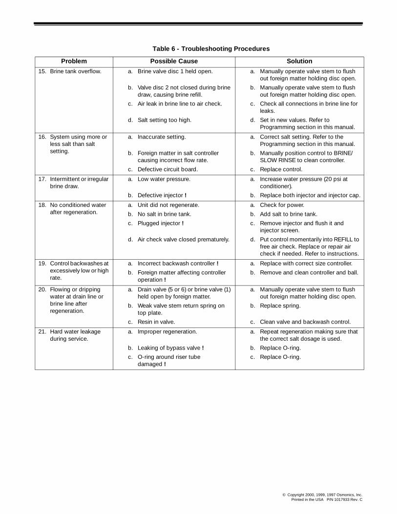
15. Brine tank overflow. a. Brine valve disc 1 held open.
b. Valve disc 2 not closed during brine draw, causing brine refill.
c. Air leak in brine line to air check.
d. Salt setting too high.
a. Manually operate valve stem to flush out foreign matter holding disc open.
b. Manually operate valve stem to flush out foreign matter holding disc open.
c. Check all connections in brine line for leaks.
d. Set in new values. Refer to Programming section in this manual.
16. System using more or less salt than salt setting.
a. Inaccurate setting.
b. Foreign matter in salt controller causing incorrect flow rate.
c. Defective circuit board.
a. Correct salt setting. Refer to the Programming section in this manual.
b. Manually position control to BRINE/SLOW RINSE to clean controller.
c. Replace control.
17. Intermittent or irregular brine draw.
a. Low water pressure.
b. Defective injector !
a. Increase water pressure (20 psi at conditioner).
b. Replace both injector and injector cap.
18. No conditioned water after regeneration.
a. Unit did not regenerate.
b. No salt in brine tank.
c. Plugged injector !
d. Air check valve closed prematurely.
a. Check for power.
b. Add salt to brine tank.
c. Remove injector and flush it and injector screen.
d. Put control momentarily into REFILL to free air check. Replace or repair air check if needed. Refer to instructions.
19. Control backwashes at excessively low or high rate.
a. Incorrect backwash controller !
b. Foreign matter affecting controller operation !
a. Replace with correct size controller.
b. Remove and clean controller and ball.
20. Flowing or dripping water at drain line or brine line after regeneration.
a. Drain valve (5 or 6) or brine valve (1) held open by foreign matter.
b. Weak valve stem return spring on top plate.
c. Resin in valve.
a. Manually operate valve stem to flush out foreign matter holding disc open.
b. Replace spring.
c. Clean valve and backwash control.
21. Hard water leakage during service.
a. Improper regeneration.
b. Leaking of bypass valve !
c. O-ring around riser tube damaged !
a. Repeat regeneration making sure that the correct salt dosage is used.
b. Replace O-ring.
c. Replace O-ring.
Table 6 - Troubleshooting Procedures