Embed Size (px)
Citation preview
The electric control valves essentially consist of either a Type 241Globe Valve or Type 244 Three-way Valve plus a Type SAMElectric Actuator. These control valves, designed according to themodular principle, can be combined with various accessoriesand feature the following special properties:– Valve body manufactured of cast iron (Type 241 Globe Valve
only), cast steel or stainless cast steel according to the ASTM(American Society for Testing and Materials) specification
– Undivided valve bonnet up to nominal size 6"– Extension bonnet or bellows seal bonnet option– Type 241 Globe Valve with valve plug – Metal sealing with
leakage rate Class IV according to IEC 534 (= Class IVaccording to ANSI B16.104), soft sealing with leakage rateClass VI or lapped-in metal sealing with leakage rate up tonominal size 3" Class IV-S2 according to IEC 534 (= Class VIaccording to ANSI B16.104); nominal size DN 4" or above,Class IV-S1 (= Class IV)
– Low-noise standard plug. Also special version with flowdivider for further noise reduction
– Type 244 Three-way Valve designed for mixing orflow-diverting service. Flow rate across port AB independentof valve stem position
Series 240
Electric Control Valve Type 241-2 Globe Valve Type 241
Electric Control Valve Type 244-2 Three-way Valve Type 244
In accordance with U.S. standards
Type 244 Three-way Valveused for mixing or flow-diverting serviceNominal sizes 1⁄⁄2" to 6" ⋅ Nominal pressureANSI Class 150 and 300 ⋅ Temperatures from–325 °F to +800 °F (–198 °C to +427 °C)
Fig. 1 ⋅ Type 241-2 Electric Control Valve with Type SAM Electric Actuator on Type 241 Globe Valve (nominal sizes 1⁄2" to 6")
Fig. 2 ⋅ Type 244-2 Electric Control Valve with Type SAM Electric Actuator on Type 244 Three-way Valve (nominal sizes 1⁄2" to 6")
Type SAM Electric ActuatorThe Type SAM Linear Actuators essentially consist of a drivingmotor and gear containing a handwheel. Actuator thrusts in therange from 2 to 25 kN. Optionally available with a.c. current orthree-phase a.c. motor; standard versions with two torque-dependent limit switch modules and three stroke-dependent limitcontacts (see Data Sheet T 8330 E for details).
Associated Information Sheet T 8010 E
Associated Data Sheetfor electric actuators T 8330 E
Edition September 1993
Data Sheet T 8043 E
VersionsStandard version for temperatures from +15 °F to +430 °F(–10 °C to +220 °C).Type 241-2 (Figs. 1 and 2) ⋅ With Type 241 Globe Valve andType SAM Electric ActuatorType 244-2 (Fig. 3) ⋅ With Type 244 Three-way Valve andType SAM Electric Actuator.Version with extension bonnet (refer to Pressure-TemperatureDiagram for permissible temperatures)Version with bellows seal bonnet consisting of a double-walled,stainless steel bellows with a backup safety stuffing box andintermediary test connectionFor Type 241-2 Electric Control Valve, also available:Version with heating jacket or heating jacket and bellowsheating for nominal sizes 1", 11⁄2", 2", 3" and 4".Version with micro-flow valve insert, nominal sizes 1⁄2" to 1",for Cv values from 0.00012 to 0.074 US GPM (Gallons PerMinute) (Kvs values from 0.0001 to 0.063 m3/h) (see Data SheetT 8018 E for details)
Conversion of valve sizing coefficients:Cv (in U.S.-gallons/min) = 1.17 ⋅ (in m3/h)Kvs (in m3/h) = 0.86 ⋅ Cv (in U.S.-gallons/min)Application
Versatile control valves designed for use in process engineeringand plants with industrial requirements.Type 241 Globe ValveNominal sizes 1⁄⁄2" to 10" ⋅ Nominal pressure ANSI Class 125to 300Temperatures from –325 °F to +800 °F (–198 °C to +427 °C)
Also available are:Type 241-2 and Type 244-2 Electric Control Valves with Type5802 Electric Actuator (see Data Sheet T 5870 E for details)Type 241-4 and Type 244-4 Electric Control Valves with Type 3274Electrohydraulic Actuator (see Data Sheet T 5874 E for details).Type 241-1 Pneumatic Control Valves (see Data Sheet T 8012 Efor details) and Type 244-1 (see Data Sheet T 8027 E for details)
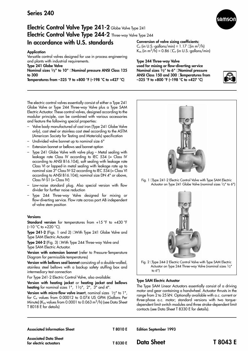
Principle of operation (Figs. 3 and 4)The process medium flows through the globe valve in the directionindicated by the arrow. The valve plug position determines thecross-sectional area of flow between the valve plug (3) and thevalve seat (2).Depending on the plug arrangement, the three-way valve oper-ates as a mixing or flow-diverting valve. With mixing valves, theprocess media to be mixed flows through valve ports A and B.The combined (joint) stream leaves at common valve port AB. Theflow from valve port A or B to common valve port AB dependson the free area between the seats (2) and valve plugs (3), andalso on the position of the plug stem (6). With flow-divertingvalves, however, the process medium flows through commonvalve port AB, and the split steams flow leave through valve portsA and B. The flow from common valve port AB to valve port Aor B corresponds to the plug stem position.The plug stem (6), with attached plug, is connected to the stem(8.1) of the actuator (8) via the stem connector (7) and sealed bymeans of a spring-loaded PTFE V-ring packing (4.2). Adjustablepacking, free of pockets, is also available for valves containingmedium which crystallizes of polymerizes (details on request).The additional metal bellows seal (9) is suitable, for instance, forvacuum under 0.022 psi (1.5 mbar), for toxic fluids and othermedia which should not escape to the outside. This version isequipped with a test connection at the top flange for checkingthe exchangeable stainless steel bellows (10).The Type 241 Globe Valves are available with St I or St III FlowDividers. When consequently installed, the seat must be replaced(see Data Sheet T 8081 E for details).The motion of the reversible motor is transmitted to the actuatorstem (8.1) of the linear actuator via a wormgear. The actuatorsare equipped with a handwheel which is stationary when themotor is being operated. When the double-throw switch isactuated, the motor is disengaged, and the handwheel is con-nected to the gear.The control valves can optionally be fitted with the accessorieslisted in section "Technical data". The limit switches issue acorresponding alarm signal whenever the set limit value isexceeded in all directions. The potentiometers are preferablyused for remote indication of the valve position. The electricalposition transmitters convert the actuator travel (0...100 %) intoa 20 mA d.c. current signal and determine the position of thelinear actuator. The position is proportional to the input signal.
Fig. 4 ⋅ Type 244-2 Electric Control Valve with Type SAM Electric Actuator on Type 244 Three-way Valve
4.1 Plug arrangement for mixing service4.2 Plug arrangement for flow-diverting service
Fig. 3 ⋅ Type 241-2 Electric Control Valve with Type SAM Electric Actuator on Type 241 Type Globe Valve (nominal sizes 1⁄2" to 10")
6 Plug stem6.1 Coupling and locknut7 Stem connector (coupling)
(also travel indicator)8 Electric actuator8.1 Actuator stem8.2 Clamp nut for actuator9 Additional metal bellows seal10 Metal bellows seal
1 Valve body2 Valve seat3 Valve plug4 Stuffing box4.1 Packing spring4.2 PTFE V-ring packing4.4 Test connection5 Valve bonnet5.1 Guide bushing5.2 Threaded bushing
2 T 8043 E
10
9
23
1
AB A
B
8
8.28.176.165.254
4.24.15.1
3
2
1
8
8.28.17
6.1
65.2544.24.15.1
3
2
1
AB A
B

Table 1 ⋅ Technical data
Valve Type 241 244
Nominal size 1⁄2" to 6" 1⁄2" to 10" 1⁄2" to 6"
ASTM material A 126 B A 216 WCB A 351 CF8M A 216 WCB A 351 CF8M
Connection FF Flange, Raised Face (RF)
Type of connection2)
FF (Flat Face) RF
Nominal pres-sure ANSI CL 125 150 or 300 150 or 300
Temperatureranges
Body, extension bonnet and bellows seal bonnet, see Pressure-Temperature Diagram
Valve plugStandard
Metal sealing−325 °F to +800 °F−198 °C to +427 °C
Soft sealing−325 °F to +428 °F−198 °C to +220 °C
–
Balanced
With PTFE ring−325 °F to +428 °F−198 °C to +220 °C
With graphite ring3)
+428 °F to +800 °F+220 °C to +427 °C
Characteristic Equal-percentage/linear/on-off Linear
Plug sealing Metal, soft or lapped-in metal Metal
Shape of plug
Type of sealingStandard Balanced with:
PTFE ring Graphitering
Leakage rate according to (DIN) IEC 534Class
Metal IV IV III
Soft VI − −
Lapped-inmetal IV−S24) − −
Rangeability 50 : 1 with 1⁄2" to 2" 30 : 1 with 21⁄2" to 10"
1) Unbalanced valve plugs with soft sealing, seat Ø ≥ 3 mm (1⁄8")2) Other versions on request3) Special version: Details on request4) Nominal size DN 4" or above; Leakage rate Class IV-S1
Table 2 ⋅ Materials (WN = Material Number according to DIN)
Standard version
Valve body1) Cast ironA 126 B
Cast carbon steelA 216 WCB
Stainless steelA 351 CF8M
Valve bonnet A 105 A 182 F 316
Seat and plug2)
WN 1.4006 WN 1.4571
Soft sealing, PTFE with glass fiber 15 %
Sealing ring for soft sealing, PTFE with carbon orgraphite
Guide bushings WN 1.4104 WN 1.4571
Stuffing box packing3)
V-ring packing of PTFE with carbon;packing spring WN 1.4310
Body gaskets Metal graphite
Version with extension bonnet
Intermediate piece A 105 A 182 F 316
Version with bellows seal bonnet
Intermediate piece A 105 A 182 F 316
Metal bellows WN 1.4571
Version with heating jacket on request
1) See Pressure-Temperature Diagram; other materials available on request2) All seats and valve plugs with metal sealing also available with Stellite facing
or plug composed of pure Stellite3) Other packing materials on request
Pressure-Temperature Diagram according to ASME/ANSI B16.1 and B16.34
3 T 8043 E
NOTE: Insulating section and ex-tension bonnet are synonymous.
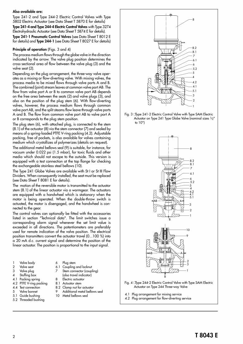
Table 3 ⋅ Technical data relating to the electric actuators
SAMSON designation SAM-10 SAM-11 SAM-20 SAM-21 SAM-22 SAM-30 SAM-31 SAM-32 SAM-40 SAM-41 SAM-42
Nominal thrust, predetermined, kN 2 4.5 6 8 12 6 8 12 15 20 25
Motor for 1)
(with handwheel)
230 V/50 Hz With mechanical brake Without brakes (with electromechanical brakes on request,) with Temperature Monitor TM
380 V/50 Hz With anti-rotationdevice With anti-rotation device
Power consumptionW
230 V/50 Hz,Stroking speed
25/50 mm/min
28/32 60/130 145/165
35/32 75/120 150/300
Transit time 25/50mm/min2)
for travel, mm
15 36 sec./18 sec.
30 72 sec./36 sec.
60 – 144 sec./72 sec.
Attachment to control valve Connection M30 x 1.5 (1⁄2" to 6") Connection M60 x 1.5 (8" to 10")
Electrical connection optionally via:(see also terminal assignments)
Terminal strip inside (standard), terminal strip with terminal boxes or compact connector, silver-plated sockets and pins3)
Switching mechanism(DE = torque-dependent switch, WE = stroke-dependent switch)
2 DE, 3 WE withsilver contacts3)
2 DE, 3 WE (standard) with silver contacts3)2 DE, 4 WE with silver contacts3)
Signalizing device(option)
Potentiometer 1 x 110/200/1000 ohm2 x 110/200/1000 ohm 4)
Electronic positiontransmitter – 0 to 20 mA
4 to 20 mA
Positioner (option) Input signal: 0 to 10 V / 0 to 20 mA / 4 to 20 mA (for motors with a.c. current 230 V/50 Hz 5)7)
Heating resistance with Temperature Monitor TM Supply voltage: AC 230 V / AC 110 V / AC 24 V
Degree of protection6) IP 65
Permissible ambient temperature −4 to 140 °F (−20 to 60 °C)
1) Other voltage and/or frequency on request2) Type SAM-10/11 Actuator available with nominal speed 17 mm/min
Type SAM-20/21/22 Actuator and SAM-30/31/32 available with speed 13.5 mm/min (without temperature monitor)3) Switching mechanism available with gold-plated contacts4) Version with potentiometers 2 x 200/2 x 1000 ohm only available for actuators without positioner5) For motors with three-phase a.c. current 380 V/50 Hz on request6) Special type of protection (e.g., for tropics, oxygen, etc.) and special enameling on request7) Version with positioner for three-phase motor only available with brake motors
4 T 8043 E

Type 241-2 Control ValvesTable 4a ⋅ Cv, Kvs values and z values for versions without flow dividers
All values apply to versions with unbalanced valve plugs. The versions in the bold-edged, shadowed fields also apply to versions with balanced valve plugs.
Cv 0.12 0.2 0.3 0.5 0.75 1.2 2 3 5 7.5 12 20 30 40 70 75 95 120 190 290 300 420 735
Kvs 0.1 0.16 0.25 0.4 0.63 1.0 1.6 2.5 4.0 6.3 10 16 25 35 60 63 80 100 160 250 260 360 630
Seat ∅ mm 3 6 12 24 31 38 48 63 80 100 125 130 150 200
in 0.12 0.24 0.47 0.945 1.22 1.5 1.9 2.48 3.15 3.94 4.92 5.12 5.91 7.87
Travel mm 15 30 15 30 60 30 60
in 0.59 1.18 0.59 1.18 2.36 1.18 2.36
Nom. size ininch (mm) z ⋅ Acoustically determined valve coefficient
1⁄2" (15) 0.8 0.8 0.8 0.8 0.75 0.65 0.65 0.6 0.55
3⁄4" (20) 0.8 0.8 0.8 0.8 0.75 0.65 0.65 0.6 0.55 0.45
1" (25) 0.8 0.8 0.8 0.8 0.75 0.65 0.65 0.6 0.55 0.45 0.4
11⁄2" (40) 0.8 0.75 0.7 0.7 0.6 0.55 0.5 0.45 0.4 0.35
2" (50) 0.8 0.75 0.7 0.7 0.6 0.55 0.5 0.45 0.4 0.35 0.35
21⁄2" (65) 0.35 0.35 0.25
3" (80) 0.35 0.35 0.25 – 0.25
4" (100) 0.25 – 0.25 0.2
6" (150) 0.2 0.2 0.2 – 0.2
8" (200) 0.2 0.2 0.2
10" (250) 0.2 0.2 0.2
Table 4b ⋅ Cv, Kvs and z values for versions with flow dividers
All values apply to versions with St I Flow Dividers. Versions marked with an asterisk are available with St III Flow Dividers. Versions in bold-edged, shadowed fields alsoavailable with balanced valve plugs.
Cv I – 1.7 2.6 4.2 7 10.5 17 26 36 62 67 85 105 170 265 275 375 650
Kvs I – 1.45 2.2 3.6 5.7 9 14.5 22 31 54 57 72 90 144 225 234 320 560
Cv III – 9 – 23 30 – 55 – 90 140 220 – 315 –
Kvs III – 7.5 – 20 26 – 47 – 75 120 190 – 270 –
Seat [mm – 12 24 31 38 48 63 80 100 125 130 150 200
in – 0.47 0.945 1.27 1.5 1.9 2.48 3.15 3.94 4.92 5.12 5.91 7.87
Travelmm 15 30 15 30 60 30 60
in 0.59 1.18 0.59 1.18 2.36 1.18 2.36
Size in inch (mm) z ⋅ Acoustically determined valve coefficient1⁄2" (15) 0.65 0.6 0.55
3⁄4" (20) 0.65 0.6 0.55
1" (25) 0.65 0.6 0.55
11⁄2" (40) 0.5 0.45 0.4* 0.35
2" (50) 0.5 0.45 0.4 0.35 0.35
21⁄2" (65) 0.35* 0.35* 0.25
3" (80) 0.35* 0.35* 0.25 – 0.25
4" (100) 0.25 – 0.25 0.2
6" (150) 0.2 0.2* – 0.2
8" (200) 0.2* 0.2* 0.2
10" (250) 0.2* 0.2* 0.2
5 T 8043 E
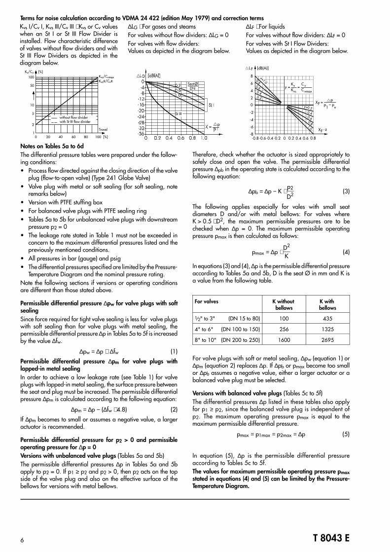
Terms for noise calculation according to VDMA 24 422 (edition May 1979) and correction termsKvs I/Cv I, Kvs III/Cv III ⋅ Kvs or Cv valueswhen an St I or St III Flow Divider isinstalled. Flow characteristic differenceof valves without flow dividers and withSt III Flow Dividers as depicted in thediagram below.
∆LF ⋅ For liquidsFor valves without flow dividers: ∆LF = 0For valves with St I Flow Dividers:Values as depicted in the diagram below.
∆LG ⋅ For gases and steamsFor valves without flow dividers: ∆LG = 0For valves with flow dividers:Values as depicted in the diagram below.
Notes on Tables 5a to 6dThe differential pressure tables were prepared under the follow-ing conditions:• Process flow directed against the closing direction of the valve
plug (flow-to-open valve) (Type 241 Globe Valve)• Valve plug with metal or soft sealing (for soft sealing, note
remarks below)• Version with PTFE stuffing box• For balanced valve plugs with PTFE sealing ring• Tables 5a to 5b for unbalanced valve plugs with downstream
pressure p2 = 0• The leakage rate stated in Table 1 must not be exceeded in
concern to the maximum differential pressures listed and thepreviously mentioned conditions.
• All pressures in bar (gauge) and psig• The differential pressures specified are limited by the Pressure-
Temperature Diagram and the nominal pressure rating.Note the following sections if versions or operating conditionsare different than those stated above.
Permissible differential pressure ∆pw for valve plugs with softsealingSince force required for tight valve sealing is less for valve plugswith soft sealing than for valve plugs with metal sealing, thepermissible differential pressure ∆p in Tables 5a to 5f is increasedby the value ∆fw.
∆pw = ∆p + ∆fw (1)
Permissible differential pressure ∆pm for valve plugs withlapped-in metal sealingIn order to achieve a low leakage rate (see Table 1) for valveplugs with lapped-in metal sealing, the surface pressure betweenthe seat and plug must be increased. The permissible differentialpressure ∆pm is calculated according to the following equation:
∆pm = ∆p − (∆fw ⋅ 4.8) (2)
If ∆pm becomes to small or assumes a negative value, a largeractuator is recommended.
Permissible differential pressure for p2 > 0 and permissibleoperating pressure for ∆p = 0Versions with unbalanced valve plugs (Tables 5a and 5b)The permissible differential pressures ∆p in Tables 5a and 5bapply to p2 = 0. If p1 ≥ p2 and p2 > 0, then p2 acts on the topside of the valve plug and also on the effective surface of thebellows for versions with metal bellows.
Therefore, check whether the actuator is sized appropriately tosafely close and open the valve. The permissible differentialpressure ∆pb in the operating state is calculated according to thefollowing equation:
∆pb = ∆p − K ⋅ p2
D2 (3)
The following applies especially for vales with small seatdiameters D and/or with metal bellows: For valves whereK > 0.5 ⋅ D2, the maximum permissible pressures are to bechecked when ∆p = 0. The maximum permissible operatingpressure pmax is then calculated as follows:
pmax = ∆p ⋅ D2
K(4)
In equations (3) and (4), ∆p is the permissible differential pressureaccording to Tables 5a and 5b, D is the seat Ø in mm and K isa value from the following table.
For valves K without bellows
K with bellows
1⁄2" to 3" (DN 15 to 80) 100 435
4" to 6" (DN 100 to 150) 256 1325
8" to 10" (DN 200 to 250) 1600 2695
For valve plugs with soft or metal sealing, ∆pw (equation 1) or∆pm (equation 2) replaces ∆p. If ∆pb or pmax become too smallor ∆pb assumes a negative value, either a larger actuator or abalanced valve plug must be selected.
Versions with balanced valve plugs (Tables 5c to 5f)The differential pressures ∆p listed in these tables also applyfor p1 ≥ p2, since the balanced valve plug is independent ofp2. The maximum operating pressure pmax is equal to themaximum permissible differential pressure.
pmax = p1max = p2max = ∆p (5)
In equation (5), ∆p is the permissible differential pressureaccording to Tables 5c to 5f.The values for maximum permissible operating pressure pmaxstated in equations (4) and (5) can be limited by the Pressure-Temperature Diagram.
6 T 8043 E
Travel
200 401
2
5
10
50
100Kv/Cv
Kvs/CvmaxKvsIII/CvIII
without flow dividerwith St III flow divider
[%]
60 80 100 [%]
( )
11
St III
.
.
.
. . . . .
Seat
-0.8-0.6-0.4 -0.2 0 0.2 0.4 0.6 0.8-8
-6
-4
-2
0
2
4
6
8
[dB(A)]L F
XF -zy=1.0
1.00.8
0.8
0.6
0.6
0.4
0.4
0.2
y=0.2
KvKvs
y =
pp1
=XF –v
p
CvCvmax
=
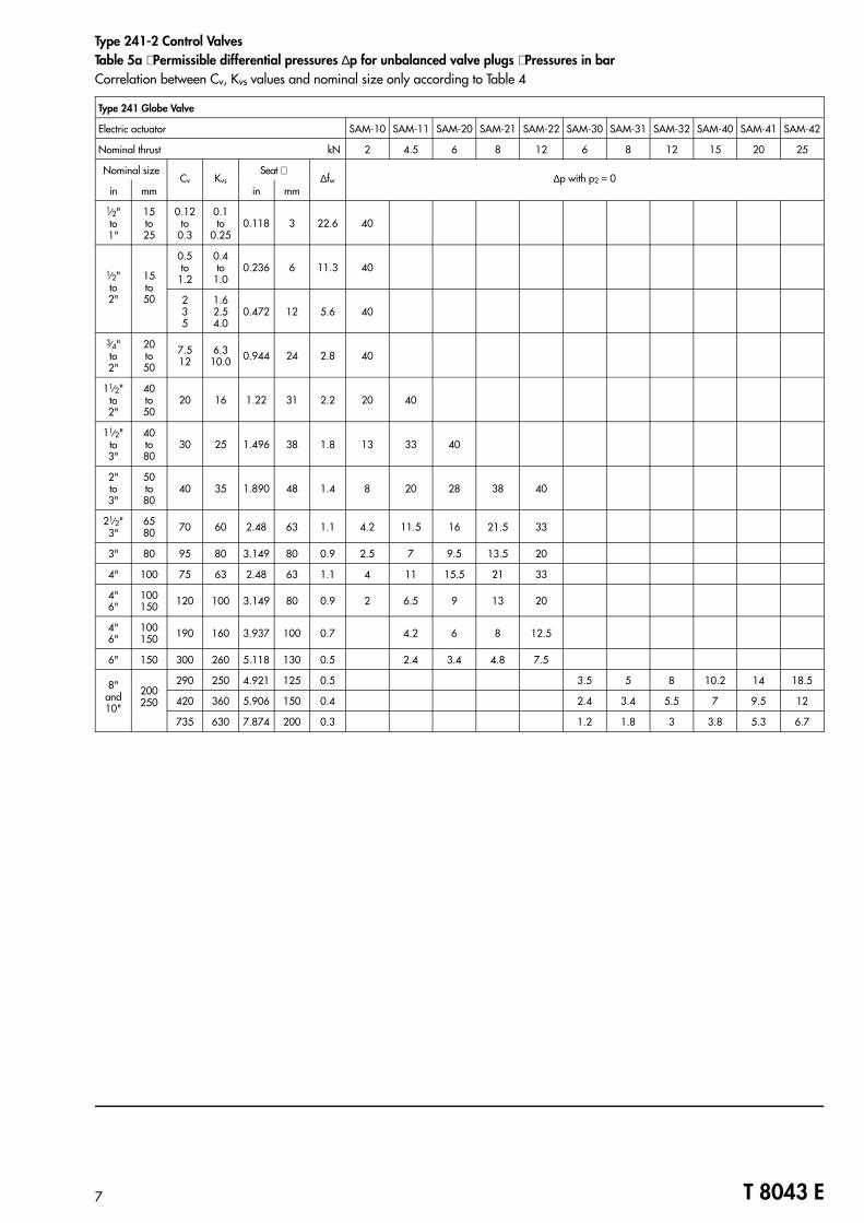
Type 241-2 Control ValvesTable 5a ⋅ Permissible differential pressures ∆p for unbalanced valve plugs ⋅ Pressures in barCorrelation between Cv, Kvs values and nominal size only according to Table 4
Type 241 Globe Valve
Electric actuator SAM-10 SAM-11 SAM-20 SAM-21 SAM-22 SAM-30 SAM-31 SAM-32 SAM-40 SAM-41 SAM-42
Nominal thrust kN 2 4.5 6 8 12 6 8 12 15 20 25
Nominal sizeCv Kvs
Seat ∅∆fw ∆p with p2 = 0
in mm in mm
1⁄2"to1"
15to25
0.12to
0.3
0.1to
0.250.118 3 22.6 40
1⁄2"to2"
15to50
0.5to
1.2
0.4to
1.00.236 6 11.3 40
235
1.62.54.0
0.472 12 5.6 40
3⁄4"to2"
20to50
7.512
6.310.0 0.944 24 2.8 40
11⁄2"to2"
40to50
20 16 1.22 31 2.2 20 40
11⁄2"to3"
40to80
30 25 1.496 38 1.8 13 33 40
2"to3"
50to80
40 35 1.890 48 1.4 8 20 28 38 40
21⁄2"3"
6580 70 60 2.48 63 1.1 4.2 11.5 16 21.5 33
3" 80 95 80 3.149 80 0.9 2.5 7 9.5 13.5 20
4" 100 75 63 2.48 63 1.1 4 11 15.5 21 33
4"6"
100150 120 100 3.149 80 0.9 2 6.5 9 13 20
4"6"
100150 190 160 3.937 100 0.7 4.2 6 8 12.5
6" 150 300 260 5.118 130 0.5 2.4 3.4 4.8 7.5
8"and10"
200250
290 250 4.921 125 0.5 3.5 5 8 10.2 14 18.5
420 360 5.906 150 0.4 2.4 3.4 5.5 7 9.5 12
735 630 7.874 200 0.3 1.2 1.8 3 3.8 5.3 6.7
7 T 8043 E
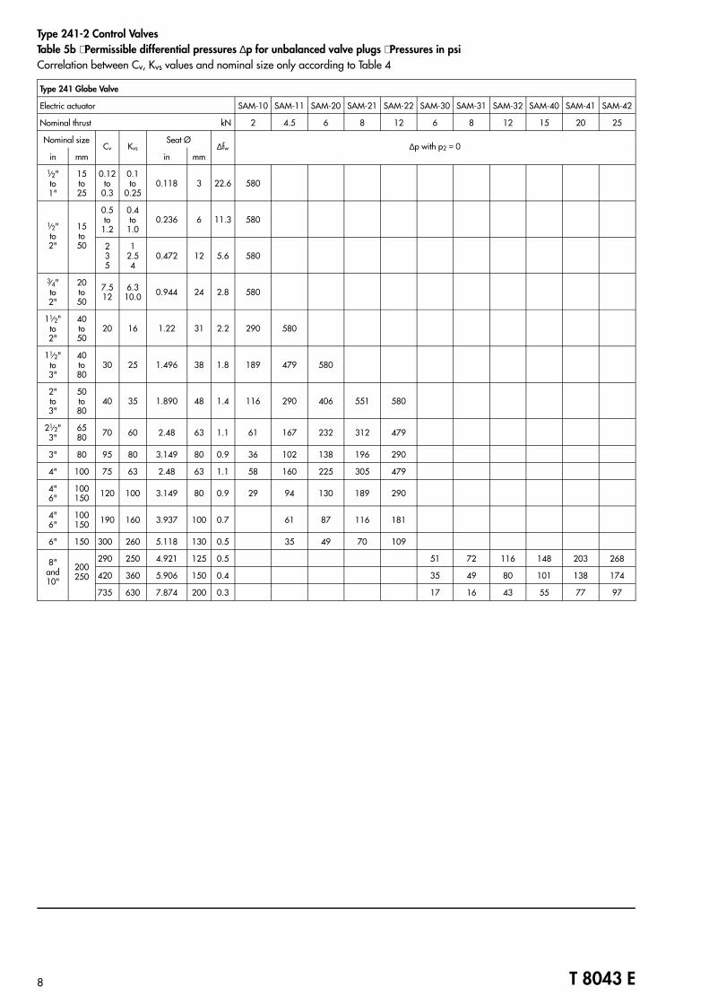
Type 241-2 Control ValvesTable 5b ⋅ Permissible differential pressures ∆p for unbalanced valve plugs ⋅ Pressures in psiCorrelation between Cv, Kvs values and nominal size only according to Table 4
Type 241 Globe Valve
Electric actuator SAM-10 SAM-11 SAM-20 SAM-21 SAM-22 SAM-30 SAM-31 SAM-32 SAM-40 SAM-41 SAM-42
Nominal thrust kN 2 4.5 6 8 12 6 8 12 15 20 25
Nominal sizeCv Kvs
Seat Ø∆fw ∆p with p2 = 0
in mm in mm
1⁄2"to1"
15to25
0.12to
0.3
0.1to
0.250.118 3 22.6 580
1⁄2"to2"
15to50
0.5to
1.2
0.4to
1.00.236 6 11.3 580
235
12.54
0.472 12 5.6 580
3⁄4"to2"
20to50
7.512
6.310.0 0.944 24 2.8 580
11⁄2"to2"
40to50
20 16 1.22 31 2.2 290 580
11⁄2"to3"
40to80
30 25 1.496 38 1.8 189 479 580
2"to3"
50to80
40 35 1.890 48 1.4 116 290 406 551 580
21⁄2"3"
6580 70 60 2.48 63 1.1 61 167 232 312 479
3" 80 95 80 3.149 80 0.9 36 102 138 196 290
4" 100 75 63 2.48 63 1.1 58 160 225 305 479
4"6"
100150 120 100 3.149 80 0.9 29 94 130 189 290
4"6"
100150 190 160 3.937 100 0.7 61 87 116 181
6" 150 300 260 5.118 130 0.5 35 49 70 109
8"and10"
200250
290 250 4.921 125 0.5 51 72 116 148 203 268
420 360 5.906 150 0.4 35 49 80 101 138 174
735 630 7.874 200 0.3 17 16 43 55 77 97
8 T 8043 E
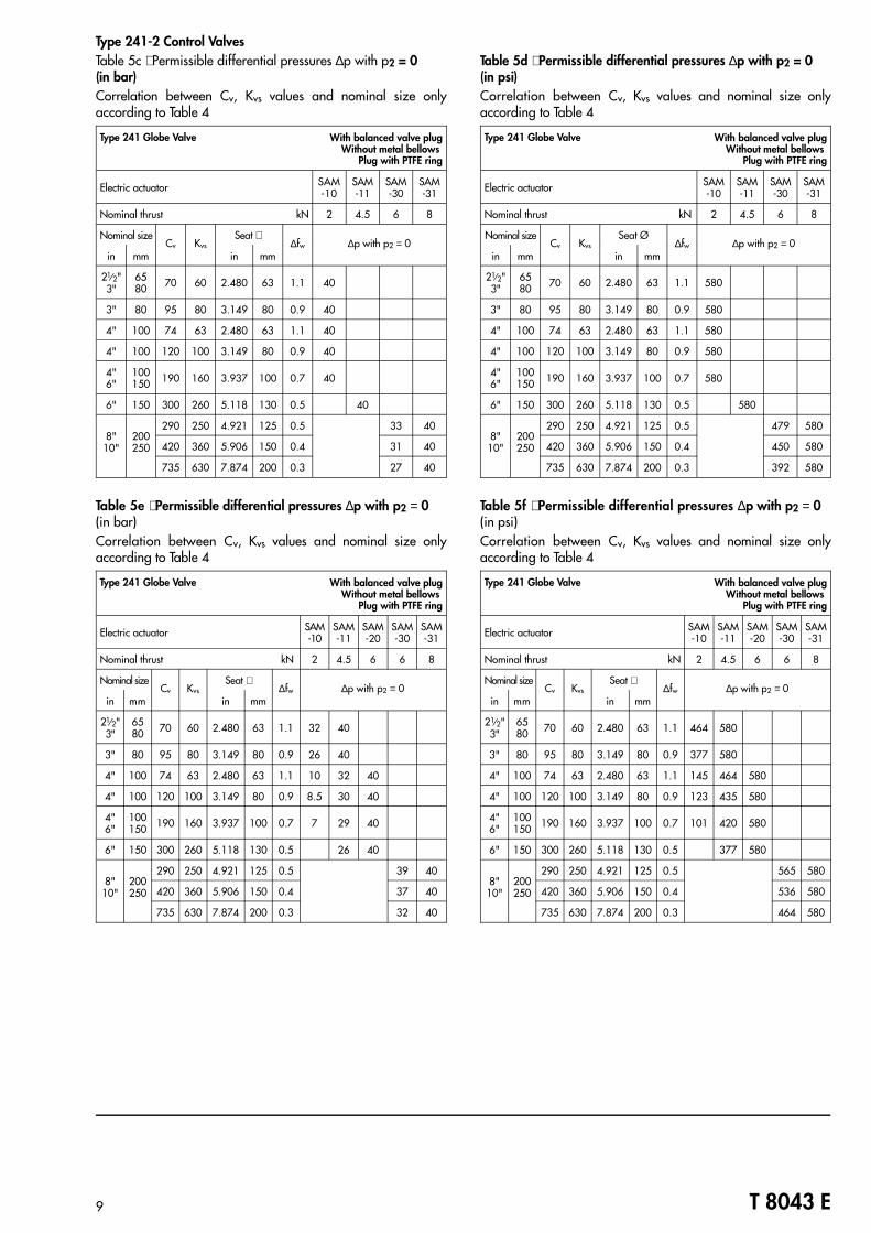
Type 241-2 Control ValvesTable 5c ⋅ Permissible differential pressures ∆p with p2 = 0 (in bar)Correlation between Cv, Kvs values and nominal size onlyaccording to Table 4
Type 241 Globe Valve With balanced valve plugWithout metal bellows
Plug with PTFE ring
Electric actuator SAM-10
SAM-11
SAM-30
SAM-31
Nominal thrust kN 2 4.5 6 8
Nominal sizeCv Kvs
Seat ∅∆fw ∆p with p2 = 0
in mm in mm
21⁄2"3"
6580 70 60 2.480 63 1.1 40
3" 80 95 80 3.149 80 0.9 40
4" 100 74 63 2.480 63 1.1 40
4" 100 120 100 3.149 80 0.9 40
4"6"
100150 190 160 3.937 100 0.7 40
6" 150 300 260 5.118 130 0.5 40
8"10"
200250
290 250 4.921 125 0.5 33 40
420 360 5.906 150 0.4 31 40
735 630 7.874 200 0.3 27 40
Table 5e ⋅ Permissible differential pressures ∆p with p2 = 0 (in bar)Correlation between Cv, Kvs values and nominal size onlyaccording to Table 4
Type 241 Globe Valve With balanced valve plugWithout metal bellows
Plug with PTFE ring
Electric actuator SAM-10
SAM-11
SAM-20
SAM-30
SAM-31
Nominal thrust kN 2 4.5 6 6 8
Nominal sizeCv Kvs
Seat ∅∆fw ∆p with p2 = 0
in mm in mm
21⁄2"3"
6580 70 60 2.480 63 1.1 32 40
3" 80 95 80 3.149 80 0.9 26 40
4" 100 74 63 2.480 63 1.1 10 32 40
4" 100 120 100 3.149 80 0.9 8.5 30 40
4"6"
100150 190 160 3.937 100 0.7 7 29 40
6" 150 300 260 5.118 130 0.5 26 40
8"10"
200250
290 250 4.921 125 0.5 39 40
420 360 5.906 150 0.4 37 40
735 630 7.874 200 0.3 32 40
Table 5d ⋅ Permissible differential pressures ∆p with p2 = 0 (in psi)Correlation between Cv, Kvs values and nominal size onlyaccording to Table 4
Type 241 Globe Valve With balanced valve plugWithout metal bellows
Plug with PTFE ring
Electric actuator SAM-10
SAM-11
SAM-30
SAM-31
Nominal thrust kN 2 4.5 6 8
Nominal sizeCv Kvs
Seat Ø∆fw ∆p with p2 = 0
in mm in mm
21⁄2"3"
6580 70 60 2.480 63 1.1 580
3" 80 95 80 3.149 80 0.9 580
4" 100 74 63 2.480 63 1.1 580
4" 100 120 100 3.149 80 0.9 580
4"6"
100150 190 160 3.937 100 0.7 580
6" 150 300 260 5.118 130 0.5 580
8"10"
200250
290 250 4.921 125 0.5 479 580
420 360 5.906 150 0.4 450 580
735 630 7.874 200 0.3 392 580
Table 5f ⋅ Permissible differential pressures ∆p with p2 = 0 (in psi)Correlation between Cv, Kvs values and nominal size onlyaccording to Table 4
Type 241 Globe Valve With balanced valve plugWithout metal bellows
Plug with PTFE ring
Electric actuator SAM-10
SAM-11
SAM-20
SAM-30
SAM-31
Nominal thrust kN 2 4.5 6 6 8
Nominal sizeCv Kvs
Seat ∅∆fw ∆p with p2 = 0
in mm in mm
21⁄2"3"
6580 70 60 2.480 63 1.1 464 580
3" 80 95 80 3.149 80 0.9 377 580
4" 100 74 63 2.480 63 1.1 145 464 580
4" 100 120 100 3.149 80 0.9 123 435 580
4"6"
100150 190 160 3.937 100 0.7 101 420 580
6" 150 300 260 5.118 130 0.5 377 580
8"10"
200250
290 250 4.921 125 0.5 565 580
420 360 5.906 150 0.4 536 580
735 630 7.874 200 0.3 464 580
9 T 8043 E

Type 244-2 Control ValvesTable 6a ⋅ Type 3244 Mixing Valve Kvs values and permissible differential pressures ∆p with p2 = 0 (in bar)
Electric actuator SAM-10 SAM-11 SAM-20 SAM-21 SAM-22
Nominal thrust kN 2 4.5 6 8 12
Nominal sizeKvs Mixing valve
Seat ∅ Travel∆p with p2 = 0
in mm mm in mm in1⁄2" 15 2 4
24 0.944
15 0.59
403⁄4" 20 2 4 6.3
1" 25 2 4 6.3 10
11⁄2"to2"
40to50
6.3 10 16 31 1.22 20 40
11⁄2"and2"
40and50
25 38 1.496 13 33 40
2"to3"
50to80
25* 40 48 1.890 8 20 28 38 40
21⁄2"and3"
65and80
60 63 2.48 4.2 11.5 16 21.5 33
3" 80 80 75 2.953 2.8 8 11 15 23
4" 100100 80 3.149
30 1.182.5 7 9.5 13.5 20
160 100 3.937 1.3 4.2 6 8 12.5
6" 150200 110 4.331 1 3.5 4.8 6.8 10.5
300 130 5.118 0.6 2.4 3.4 4.8 7.5
Table 6b ⋅ Type 3244 Mixing Valve Cv values and permissible differential pressures ∆p with p2 = 0 (in psi)
Electric actuator SAM-10 SAM-11 SAM-20 SAM-21 SAM-22
Nominal thrust kN 2 4.5 6 8 12
Nominal sizeCv Mixing valve
Seat ∅ Travel∆p with p2 = 0
in mm mm in mm in1⁄2" 15 2.34 5
24 0.944
15 0.59
5803⁄4" 20 2.34 5 7.5
1" 25 2.34 5 7.5 12
11⁄2"to2"
40to50
7.5 12 20 31 1.22 290 580
11⁄2"and2"
40and50
30 38 1.496 189 478 580
2"to3"
50to80
30 47 48 1.890 116 290 406 551 580
21⁄2"and3"
65and80
70 63 2.48 61 167 232 312 478
3" 80 95 75 2.953 41 116 160 217 333
4" 100120 80 3.149
30 1.1836 101 138 196 290
190 100 3.937 189 61 43 116 181
6" 150230 110 4.331 15 51 70 99 152
350 130 5.118 9 35 49 70 109
10 T 8043 E

Table 6c ⋅ Type 3244 Flow-diverting Valve Kvs values and permissible differential pressures ∆p with p2 = 0 (in bar)
Electric actuator SAM-10 SAM-11 SAM-20 SAM-21 SAM-22
Nominal thrust kN 2 4.5 6 8 12
Nominal size Kvs Flow-divertingvalve
Seat ∅ Travel∆p with p2 = 0
in mm mm in mm in1⁄2" 15 2 4
24 0.944
15 0.59
403⁄4" 20 2 4 6.3
1" 25 2 4 6.3 10
11⁄2"to2"
40to50
6.3 10 16 31 1.22 20 40
11⁄2"and2"
40and50
25 38 1.496 13 33 40
2"to3"
50to80
25 40 48 1.890 8 20 28 38 40
21⁄2" 65 60/40 63/48
2.48/1.890 4.2 11.5 16 21.5 33
3" 8060 63 2.48 4.2 11.5 16 21.5 33
80/60 75/63
2.953/2.48 2.8 8 11 15 23
4" 100100 80 3.149
30 1.182.5 7 9.5 13.5 20
160/100 100/80
3.937/3.149 1.3 4.2 6 8 12.5
6" 150200 110 4.331 1 3.5 4.8 6.8 10.5
300/200 130/110
5.118/4.331 0.6 2.4 3.4 4.8 7.5
Table 6d ⋅ Type 3244 Flow-diverting Valve Cv values and permissible differential pressures ∆p with p2 = 0 (in psi)
Electric actuator SAM-10 SAM-11 SAM-20 SAM-21 SAM-22
Nominal thrust kN 2 4.5 6 8 12
Nominal size Cv Flow-divertingvalve
Seat ∅ Travel∆p with p2 = 0
in mm mm in mm in1⁄2" 15 2.34 5
24 0.944
15 0.59
5803⁄4" 20 2.34 5 7.5
1" 25 2.34 5 7.5 12
11⁄2"to2"
40to50
7.5 12 20 31 1.22 290 580
11⁄2"and2"
40and50
30 38 1.496 189 478 580
2"to3"
50to80
30 47 48 1.890 116 290 406 551 580
21⁄2" 65 70/47 63/48
2.48/1.890 61 167 232 312 478
3" 8070 63 2.48 61 167 232 312 478
95/70 75/63
2.953/2.48 41 116 160 217 333
4" 100120 80 3.149
30 1.1836 101 138 196 290
190/120 100/80
3.937/3.149 19 61 43 116 181
6" 150230 110 4.331 15 51 70 99 152
350/230 130/110
5.118/4.331 9 35 49 70 109
11 T 8043 E
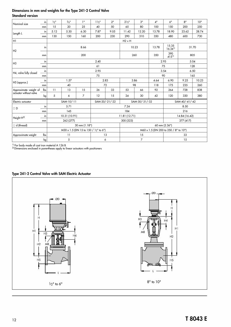
Dimensions in mm and weights for the Type 241-2 Control Valve Standard version
Nominal sizein 1⁄2" 3⁄4" 1" 11⁄2" 2" 21⁄2" 3" 4" 6" 8" 10"
mm 15 20 25 40 50 65 80 100 150 200 250
Length Lin 5.12 5.30 6.30 7.87 9.05 11.42 12.20 13.78 18.90 23.62 28.74
mm 130 150 160 200 230 290 310 350 480 600 730
H1 H2 + H
H2in 8.66 10.23 13.78 15.35
16.341) 31.70
mm 200 260 350 3904151) 805
H3in 2.40 2.95 5.04
mm 61 75 128
H4, valve fully closedin 2.95 3.54 6.50
mm 75 90 165
H5 (approx.)in 1.57 2.83 3.86 4.64 6.90 9.25 10.23
mm 40 72 98 118 175 235 260
Approximate weight ofactuator without valve
lbs 11 13 15 26 33 53 66 92 264 728 838
kg 5 6 7 12 15 24 30 42 120 330 380
Electric actuator SAM-10/-11 SAM-20/-21/-22 SAM-30/-31/-32 SAM-40/-41/-42
∅ Din 5.71 7.24 8.50
mm 145 184 216
Height H2) in 10.31 (10.91) 11.81 (12.71) 14.84 (16.42)
mm 262 (277) 300 (323) 377 (417)
∅ d (thread) 30 mm (1.18") 60 mm (2.36")
M30 x 1.5 (DN 15 to 150 / 1⁄2" to 6") M60 x 1.5 (DN 200 to 250 / 8" to 10")
Approximate weight lbs 11 13 15 33
kg 5 6 7 15
1) For body made of cast iron material A 126 B2) Dimensions enclosed in parentheses apply to linear actuators with positioners
1⁄2" to 6" 8" to 10"
12 T 8043 E
ØD
M8
ØD
H3
M8
L
Type 241-2 Control Valve with SAM Electric Actuator
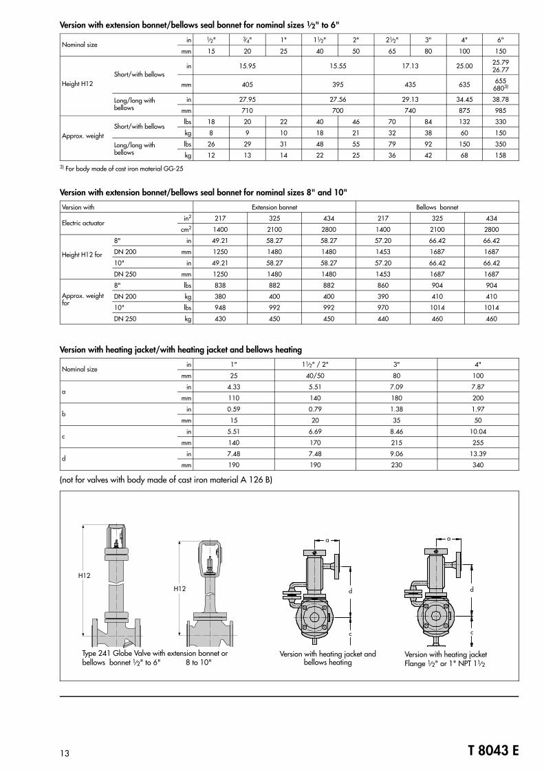
Version with extension bonnet/bellows seal bonnet for nominal sizes 1⁄⁄2" to 6"
Nominal sizein 1⁄2" 3⁄4" 1" 11⁄2" 2" 21⁄2" 3" 4" 6"
mm 15 20 25 40 50 65 80 100 150
Height H12Short/with bellows
in 15.95 15.55 17.13 25.00 25.7926.77
mm 405 395 435 635 6556803)
Long/long withbellows
in 27.95 27.56 29.13 34.45 38.78
mm 710 700 740 875 985
Approx. weightShort/with bellows
lbs 18 20 22 40 46 70 84 132 330
kg 8 9 10 18 21 32 38 60 150
Long/long withbellows
lbs 26 29 31 48 55 79 92 150 350
kg 12 13 14 22 25 36 42 68 158
3) For body made of cast iron material GG-25
Version with extension bonnet/bellows seal bonnet for nominal sizes 8" and 10"
Version with Extension bonnet Bellows bonnet
Electric actuatorin2 217 325 434 217 325 434
cm2 1400 2100 2800 1400 2100 2800
Height H12 for
8" in 49.21 58.27 58.27 57.20 66.42 66.42
DN 200 mm 1250 1480 1480 1453 1687 1687
10" in 49.21 58.27 58.27 57.20 66.42 66.42
DN 250 mm 1250 1480 1480 1453 1687 1687
Approx. weightfor
8" lbs 838 882 882 860 904 904
DN 200 kg 380 400 400 390 410 410
10" lbs 948 992 992 970 1014 1014
DN 250 kg 430 450 450 440 460 460
Version with heating jacket/with heating jacket and bellows heating
Nominal sizein 1" 11⁄2" / 2" 3" 4"
mm 25 40/50 80 100
ain 4.33 5.51 7.09 7.87
mm 110 140 180 200
bin 0.59 0.79 1.38 1.97
mm 15 20 35 50
cin 5.51 6.69 8.46 10.04
mm 140 170 215 255
din 7.48 7.48 9.06 13.39
mm 190 190 230 340
(not for valves with body made of cast iron material A 126 B)
Type 241 Globe Valve with extension bonnet or bellows bonnet 1⁄2" to 6" 8 to 10"
Version with heating jacket andbellows heating
Version with heating jacketFlange 1⁄2" or 1" NPT 11⁄2
13 T 8043 E
a
d
c
H12
H12
a
d
c
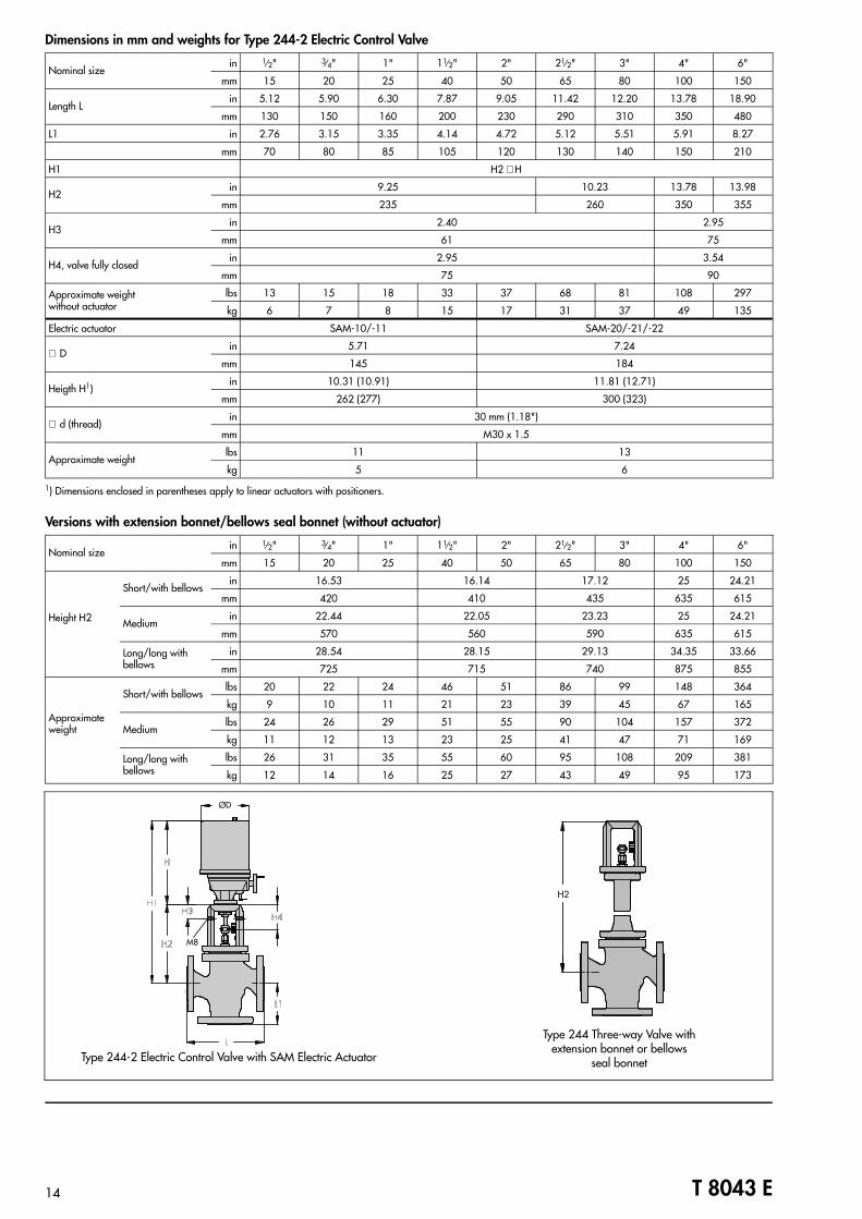
Dimensions in mm and weights for Type 244-2 Electric Control Valve
Nominal sizein 1⁄2" 3⁄4" 1" 11⁄2" 2" 21⁄2" 3" 4" 6"
mm 15 20 25 40 50 65 80 100 150
Length Lin 5.12 5.90 6.30 7.87 9.05 11.42 12.20 13.78 18.90
mm 130 150 160 200 230 290 310 350 480
L1 in 2.76 3.15 3.35 4.14 4.72 5.12 5.51 5.91 8.27
mm 70 80 85 105 120 130 140 150 210
H1 H2 + H
H2in 9.25 10.23 13.78 13.98
mm 235 260 350 355
H3in 2.40 2.95
mm 61 75
H4, valve fully closedin 2.95 3.54
mm 75 90
Approximate weight without actuator
lbs 13 15 18 33 37 68 81 108 297
kg 6 7 8 15 17 31 37 49 135
Electric actuator SAM-10/-11 SAM-20/-21/-22
∅ Din 5.71 7.24
mm 145 184
Heigth H1)in 10.31 (10.91) 11.81 (12.71)
mm 262 (277) 300 (323)
∅ d (thread)in 30 mm (1.18")
mm M30 x 1.5
Approximate weightlbs 11 13
kg 5 6
1) Dimensions enclosed in parentheses apply to linear actuators with positioners.
Versions with extension bonnet/bellows seal bonnet (without actuator)
Nominal sizein 1⁄2" 3⁄4" 1" 11⁄2" 2" 21⁄2" 3" 4" 6"
mm 15 20 25 40 50 65 80 100 150
Height H2
Short/with bellowsin 16.53 16.14 17.12 25 24.21
mm 420 410 435 635 615
Mediumin 22.44 22.05 23.23 25 24.21
mm 570 560 590 635 615
Long/long withbellows
in 28.54 28.15 29.13 34.35 33.66
mm 725 715 740 875 855
Approximateweight
Short/with bellowslbs 20 22 24 46 51 86 99 148 364
kg 9 10 11 21 23 39 45 67 165
Mediumlbs 24 26 29 51 55 90 104 157 372
kg 11 12 13 23 25 41 47 71 169
Long/long withbellows
lbs 26 31 35 55 60 95 108 209 381
kg 12 14 16 25 27 43 49 95 173
Type 244-2 Electric Control Valve with SAM Electric Actuator
Type 244 Three-way Valve withextension bonnet or bellows
seal bonnet
14 T 8043 E
ØD
M8
H2
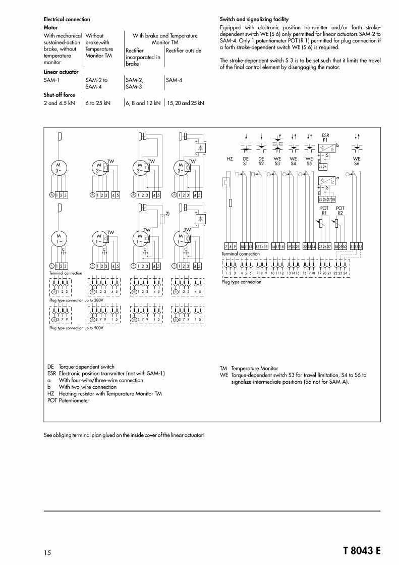
See obliging terminal plan glued on the inside cover of the linear actuator!
Electrical connectionMotorWith mechanicalsustained-actionbrake, withouttemperaturemonitor
Without brake,with Temperature Monitor TM
With brake and Temperature Monitor TM
Rectifier incorporated in brake
Rectifier outside
Linear actuatorSAM-1 SAM-2 to
SAM-4 SAM-2, SAM-3
SAM-4
Shut-off force2 and 4.5 kN 6 to 25 kN 6, 8 and 12 kN 15, 20 and 25 kN
Switch and signalizing facilityEquipped with electronic position transmitter and/or forth stroke-dependent switch WE (S 6) only permitted for linear actuators SAM-2 toSAM-4. Only 1 potentiometer POT (R 1) permitted for plug connection ifa forth stroke-dependent switch WE (S 6) is required.
The stroke-dependent switch S 3 is to be set such that it limits the travelof the final control element by disengaging the motor.
15 T 8043 E
DE Torque-dependent switchESR Electronic position transmitter (not with SAM-1)a With four-wire/three-wire connectionb With two-wire connectionHZ Heating resistor with Temperature Monitor TMPOT Potentiometer
TM Temperature MonitorWE Torque-dependent switch S3 for travel limitation, S4 to S6 to
signalize intermediate positions (S6 not for SAM-A).
Selection and sizing of the control valve1. Calculate the appropriate Cv or Kvs values according to
(DIN) IEC 534.2. Select the nominal size DN and Cv or Kvs value according to
Table 4 or 6.3. Determine the permissible differential pressure ∆p as indi-
cated in Table 5 or 6.4. Select the appropriate actuator as indicated in Table 3 with
consideration of nominal thrust, travel and transit time (transittime ≥ 30 s when connected to three-step controller).
5. Selection of materials, pressure and temperature accordingto Tables 1 and 2 and the Pressure-Temperature Diagram
6. Accessories according to Tables 1, 2 and 3
Specifications subject to change without notice.
Ordering textType Nominal size DN ANSI ClassValve plug(Type 241 Globe Valve):
Standard or balancedMetal sealing, soft sealingor lapped-in metal sealing
Function(Type 244 Three-way Valve):
Mixing or flow-diverting valve
Characteristic: Equal-percentage1), linear oron-off
Body material: According to Table 2Process fluid and associated density in lb/cu.ft or kg/m3
Maximum flow rate in lbs/hr or kg/h or cu.ft/min or m3/h undernormal or operating conditionsUpstream pressure p1 in psi or bar (absolute
pressure pabs)Downstream pressure p2 in psi or barTemperature of process medium in °F, °C or KActuator: Type and version, additional equipment such as limitswitches, potentiometers, electric position transmitters
1) Type 241 Globe Valve only
SAMSON AG ⋅ MESS- UND REGELTECHNIKWeismüllerstraße 3 ⋅ D-60314 Frankfurt am MainPostfach 10 19 01 ⋅ D-60019 Frankfurt am MainTelefon (0 69) 4 00 90 ⋅ Telefax (0 69) 4 00 95 07 T 8043 E


![MPA valve terminal - Festo...MPA pneumatics manual Valve terminal with MPA pneumatics Type VT32−.. Manual 534 241 en 0302NH [665 561] MPA valve terminal Contents and general instructions](https://img.pdfslide.us/doc/110x75/5ea5fab1dace5b6e75520cde/mpa-valve-terminal-festo-mpa-pneumatics-manual-valve-terminal-with-mpa-pneumatics.jpg)