Embed Size (px)
Citation preview
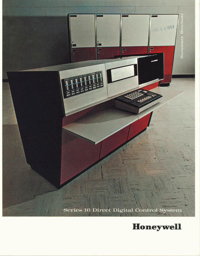
Honeywell

INTRODUCING T H E HONEYWELL SERIES 16 DDC SYSTEM
The Honeywell Series 16 Direct Digital Control (DDC) System is a modular hardwarelsoftware functional package for the process control industry. Super- visory control, optimization, and report generation can be implemented on line, while performing direct digital control. The package allows the user to con-f igure his par t icu lar system in an efficient manner. Significant economic advantages may be realized at each stage of his project -from initial sys- tem analysis, through startup, use, and future expansion. These advantages are achieved through:
System integrity Ease of system implementation System modularity
System Integrity
Reliability -The integrated-circuit cen- tral processor combines high speed with field-proven performance and reliability.
lnput Isolation and Protection -lnput lines are isolated from noise sources and protected from accidental connec- tion to high voltages.
lnput Accuracy and Sensitivity -The analog conver ter ut i l izes successive approximation, 13 bits plus sign. Accu- racy is k . 0 5 percent of full scale for low-level analog inputs.
Software Error Checks -Analog inputs are checked against standards and compared with process variable limits.
Analog Output Validity -A unique out- put validity subsystem provides hard-ware monitoring to insure correctness of station addressing and data update.
System-Integrated Backup Stations -Automatic and manual analog backup stations were designed as integral parts of the overall system. They operate with the output validity system to insure com- patibility and control system integrity.
System Implementation
Simplified Data Entry - The Series 16 DDC System utilizes simplified loop data entry with table-filling techniques. This reduces the time normally required to implement sof tware fo r a D D C system.
OLERT Operating System Support- The DDC system software, Controlware I, is supported by OLERT, an advanced real-time operating system which pro- vides convenient and powerful multipro- gramming facilities.
FORTRAN Compat ib i l i t y -The user m a y u t i l i z e H o n e y w e l l R e a l - T i m e FORTRAN IV in writing his special real- time I /O as well as supervisory pro-grams for operation under the OLERT executive.
Standard Control Analysis -The Con-trolware program utilizes a full value positional algorithm, non-interacting in the frequency domain.
Compat ib le P ID Set t ings - Dig i ta l mode control settings are the same as analog backup station settings. Tuning the loop will result in a single set of constants for both the algorithm and the backup controller.
Operator Interface - The operator's console provides for complete overview and control of the process, insuring high reliability through features such as key- lock control and area concepts.
System Modularity
Modular Structure - The Series 16 DDC System is uniquely modular in de- sign. The software has been structured to handle hardware expansion and soft- ware additions.
Foreground/Background Programming -On-line program development may be performed in a background mode using real-time language.
Special Control Routine Additions -Controlware is modular, and provision is made for convenient links to special control routines.
General Algorithm Data Entry - The algorithm is structured for convenient on-line or off-line entry of data and loop parameters into its table segments.
lnput Scan Structure -The input soft- ware routine is modularized by functions and provides for signal conditioning. There are standard routines for lineari- zation and conversion; linkages are provided for special routines.
Operator's Console Modular Software -Operator's console software is easy to use in implementing special func-tions and variations of displays.
System Configuration -The modularity and ease of expansion of the Series 16 DDC System offers to the user a func- tional package which he can utilize to configure his system uniquely for mayi- mum benefits.
0 1968 Honeywell, Computer Control Division

STANDARD SERIES 16 DDC FUNCTIONS
Accepts analog and digital information from a wide variety of process sensors.
Provides variable scan frequencies in multiples of r/4 second cycles.
Prints accurate reports of plant status in clear, readable formats with all values in logical or engineering units.
Records process variable alarm condi- tions as they occur; calls for operator attention and types alarm summaries for future reference.
Provides area-concept for multiple op- erator's consoles.
Provides for remote operation of op-erator's consoles and backup stations.
Provides foreground/background pro-cessing capability.
Provides three-mode proportional. in- tegral derivative (PID) computer con-trol with full-value positional algorithm.
All mode switches between computer and stations are bumpless transfers.
Hardware error detection can trigger bumpless transfer from computer to stations.
Provides computer manual mode opera- tion from operator's consoles.
Provides nonlinear compensation for valve saturation, reset windup and batch startup.
Limits rate-of-change of valve output to protect against unstable process con- ditions.
Utilizes unique validity checks to insure system integrity.
Utilizes table-filling loop data entry.

I
SYSTEM DESCRIPTION
Central Processor Unit (CPU)
The DDP-516 CPU is an integrated-circuit, general-purpose computer fea- turing extremely high computational and input-output speeds. The basic 16-bit word format is used with a 32K-word core memory and a cycle time of 960 nanoseconds to provide unique capa- bilities for direct digital control. Stan- dard hardware capabilities supported by the DDC package includes:
9 Memory Lockout High-speed Arithmetic Real-Time Clock
Process Interface Controller (PIC)
Provides terminal connections for field input and output lines. Provides means for the central pro- cessor to communicate efficiently and at machine speed with process signals by effectively buffering input- output-device response times.
9 Conditions and converts input signals to a proper computer format. Converts computer output data to a form and level acceptable to the pro- cess actuators and peripherals. Provides isolation from electrical noise introduced at remote devices and/or i n l ines between f ie ld - mounted devices and the computer. Provides protection from accidentally applied voltages on field input/output signal lines.
Analog lnput Subsystem
The analog input hardware - signal conditioning boards and A/D converter - is contained in the PIC. Associated with the hardware is the Analog lnput Subsystem performing functions such as:
9 Point selection Reading of analog inputs Drift and offset correction Limit checking of analog inputs Linearization and conversion Special functions specified by the user
Message Center
The message center consists of logging and alarm typewriters with associated software which arranges and outputs data from the typewriters. The message software accepts requests from the typewriters, formats a message and initiates its typeout. This software is used for all standard alarm and error messages, validation of console en- tries and standard process-variable summaries.
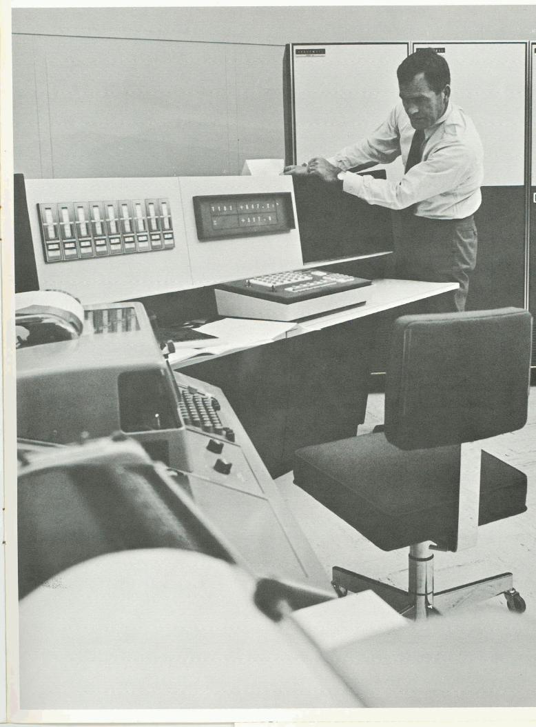
Operator's Console
The standard operator's console, avail- able in rack or table-mounted configur- ations, is divided into two devices: a display device with its associated power supply and a keyboard device. As many as four consoles can be supplied per system. The display device can contain as many as four registers of rear pro- jection units.
Associated with the operator's console is a package of related software pro- viding additional protection against in- valid entries in two ways:
Each time a button is depressed, a visual action occurs on the display. This "character echo" function in-sures that the information was re-ceived accurately by the computer. Reasonability tests are made for most entries. Examples are:
1. Nonexistent point or loop I.D. 2. Entry value beyond allowable
range 3. Key lock violation
Whenever a violation is found, an ] 1 "error" message is displayed in the con- ., sole function window, and the entry is rejected. I
DDC Analog Output Subsystem
This subsystem interfaces the PIC with the process value outputs required for control. Each subsystem has the capac- ity for up to seven groups of DDC backup control stations with a maximum capacity of 72 stations per group. One station logic interface (SLI) unit is used for each station group. The SLI provides the stations with address decoding, D/A signal buffering, validity checking and analog feedback signal buffering.

DDC Backup Stations
Design Features System-integrated stations Bumpless transfer to and from all modes Valve-position feedback Automatic computer-to-station switching Operator readout Modular station design Preset manual option Battery-power backup option
These stations are supplied in the man-ual and three-mode configuration. Three types of stations are available:
Manual Station -Provides manual ad-justment of 4-20 ma signals in a backup mode.
Standard Three-Mode Station - Pro-vides for either manual adjustment of the 4-20 ma signal or three-mode auto-matic control in backup operation. The station set point is manually adjusted by the operator.
Tracking Three-Mode Station - Pro-vides for either manual adjustment of the 4-20 ma signal or three-mode auto-matic control in backup operation. The station set point automaticallytracks the process variable when the station is under computer control.
System Validity Checks
System validity checks insure that hard-ware failure will not create a system upset which could cause product loss, equipment destruction or a safety hazard. To accomplish this integrity, the Series 16 DDC System detects symp-toms of hardware failures before the failures have caused the process to be drastically upset. It will abort DDC con-trol with all valves at a safe operating level when it is determined that the time-shared portion of the system is no longer effective in control.

EXTENSIVE SOFTWARE
OLERT
OLERT (On-Line Executive for Real Time) is the operating system which provides the multiprogramming capabil- ity that supports the DDC software (Controlware) and custom user pro- grams in the Series 16 DDC System. OLERT coordinates the operation of the central processor unit and associated peripheral equipment, allocating re- sources to meet the demands of the process. OLERT schedules applications programs and peripheral interface pro- grams based on time, priority interrupts and operator requests. The program allocates memory, handles interrupt re- sponses, maintains an internal clock and timers, provides job-oriented memory protection and permits com-munication among programs and be-tween the software and the operator.
Controlware I
Operating directly under OLERT is Con- trolware I, structured into three basic software subsystems: Analog Process- ing Subsystem, Operator's Console Subsystem and Message Center Sub- system.
DDC Analog Processing Subsystem Software -The DDC System Software services the Analog Input Subsystem and individual DDC stations. The soft- ware scans and processes analog inputs (points) either at a predetermined in- terval or upon request. Processing in- cludes inputting points, correcting points for drift and offset, performing linearization, normalizing and limit checking as required. Utilizing a double buffering technique, the software insures high-speed processing of input/ output information to individual DDC stations.
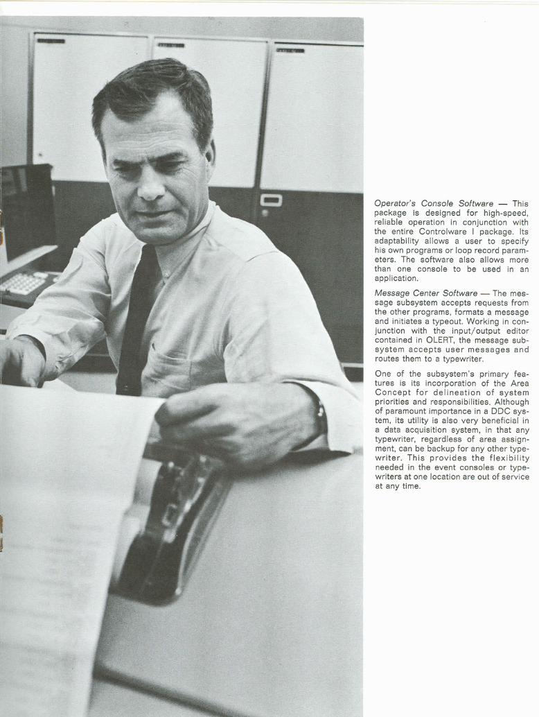
Operator's Console Software - This package is designed for high-speed, reliable operation in conjunction with the entire Controlware I package. Its adaptability allows a user to specify his own programs or loop record param- eters. The software also allows more than one console to be used in an application.
Message Center Software -The mes- sage subsystem accepts requests from the other programs, formats a message and initiates a typeout. Working in con- junction with the input/output editor contained in OLERT, the message sub- system accepts user messages and routes them to a typewriter.
One of the subsystem's primary fea- tures is its incorporation of the Area Concept for delineation of system priorities and responsibilities. Although of paramount importance in a DDC sys- tem, its utility is also very beneficial in a data acquisition system, in that any typewriter, regardless of area assign-ment, can be backup for any other type- writer. This provides the flexibility needed in the event consoles or type- writers at one location are out of service at any time.

WIDE VARIETY OF APPLICATIONS
The Series 16 Direct Digital Control System, designed to handle most current applications effectively and ac- curately, has the state-of-the-art sophis- t i ca t ion needed t o handle fu ture applications as well.
Because of its flexible and versatile modular design approach, the Series 16 DDC System is suitable for a wide range of applications. Modularity of design also permits easy expansion to include supervision and optimization. Computer-directed data acquisition and cont ro l systems manufactured b y Honeywell have already proved their worth in a number of areas, such as:
Nuclear and conventional power plants Blast furnaces Continuous casting Textile dyeing Paper mill monitoring Food making Cigarette production Metals producing Petrochemical processing Pipeline control Mining


EASY IMPLEMENTATION
User programming time and costs are substantially reduced by table-filling techniques which provide standard Con- trolware programs with loop and control parameters.
Analog Input Subsystem tables are user- tabulated for loop parameters. Addi-tional tables in this subsystem are used to group analog points and provide temporary storage, define engineering units and give ranges of values, and handle input buffer tables. The Opera- tor's Console Subsystem tables identify console display parameters and console keyboard parameters. Message Center Subsystem tables give a directory of messages and abbreviations and output- device identification. General System tables provide a directory of tables in the system, area designation and trans- lation and conversion parameters.
The ease and flexibility of implementing the Honeywell Series 16 DDC System allows users to quickly reach a level of proficiency that lets them put the capa- bilities of the system to good use.
EXTENSIVE SUPPORT SERVICES
Honeywell provides all the assistance necessary to implement its direct digital control system. Training programs include:
Extensive documentation and easy im- plementation allow a user to absorb details about the system quickly. As a result, little time is necessary to attain the level of proficiency necessary for complete utilization of the system's capabilities.
Further support is provided in the form of systems engineering personnel, pro- gramming people and applications ana lys ts , bo th i n t he f i e l d and a t Honeywell's Computer Control Division for initial installation and future support.
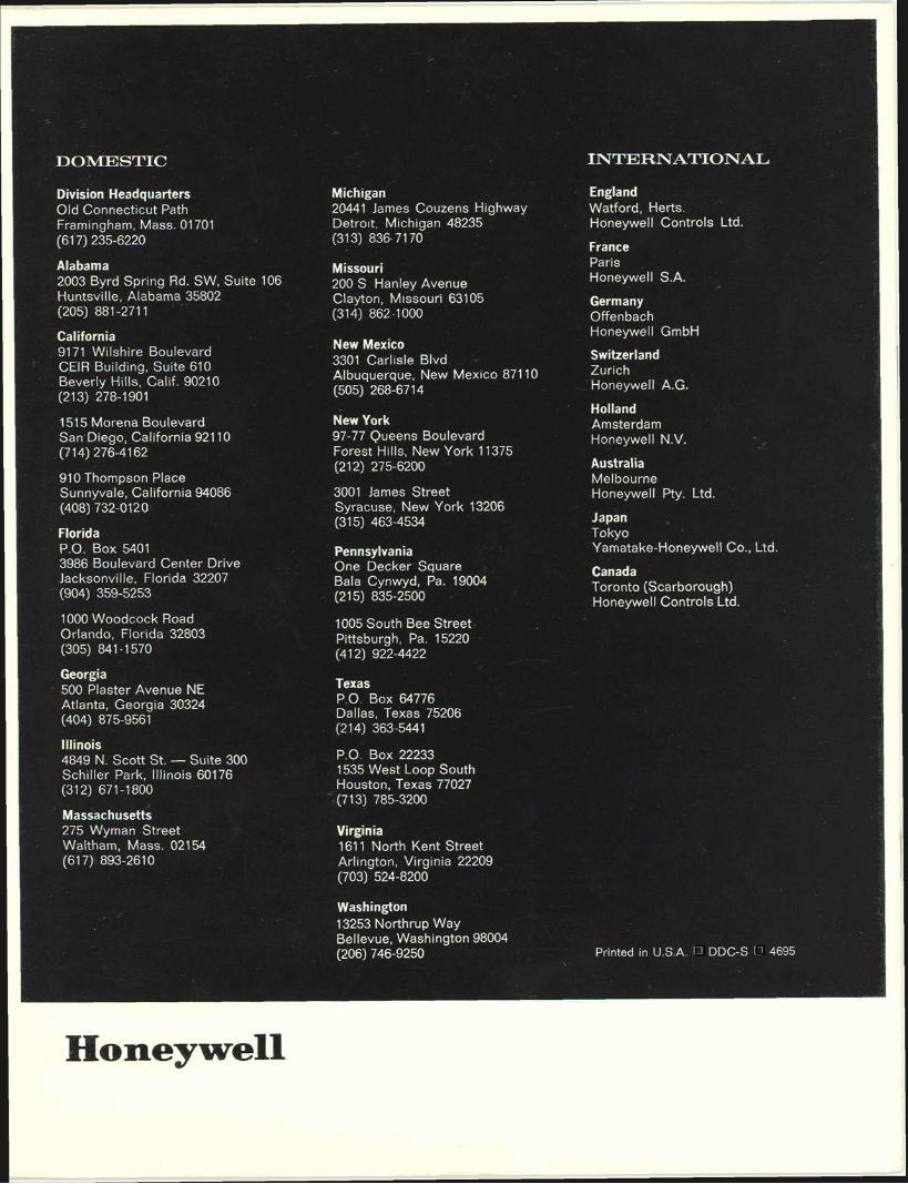
DOMESTIC
Division Headquarters Old Connecticut Path Framingham, Mass. 01701 (61 7) 235-6220
Alabama 2003 Byrd Spring Rd. SW, Suite 106 Huntsville, Alabama 35802 (205) 88 1 -27 1 1
California 9171 Wilshire Boulevard CElR Building, Suite 610 Beverly HilCs, Calif. 90210 (213) 278-1901
1515 Morena Boulevard San Diego, California 921 10 (7 14) 276-4 1 62
910 Thompson Place Sunnyvale, Californ~a 94086 (408) 732-012 0
Florida P.O. Box 5401 3986 Boulevard Center Drive Jacksonville, Florida 32207
' (904) 359-5253
1000 Woodcock Road Orlando, Florida 32803 (305) 841 -1 570
Georgia 500 Plaster Avenue NE Atlanta, Georgia 30324 (404) 875-956 1
Illinois 4849 N. Scott St. - Suite 300 Schiller Park, Illinois 60176 (312) 671-1800
~assachusetti 275 Wyrnan Street Waltham, Mass. 021 54 (61 7) 893-261 0
Michigan 20441 James Couzens Highway Detro~t, Michigan 48235 (31 3) 836- 7 1 70
Missouri 200 S Hanley Avenue Clayton, M~ssouri 63105 (314) 862-1000
New Mexico 3301 Carlisle Blvd Albuquerque, New Mexico 871 10 (505) 268-67 14
New York 97-77 Queens Boulevard Forest Hills, New York 11 375 (21 2) 275-6200
3001 James Street Syracuse, New York 13206 (31 5) 463-4534
Pennsylvania One Decker Square Bala Cynwyd. Pa. 19004 (21 5) 835-2500
1005 South Bee Street Pittsburgh, Pa. 15220 (41 2) 922-4422
Texas P.O. Box 64776 Dallas, Texas 75206 (2 14) 363-544 1
P.O. Box 22233 1535 West Loop South Houston, Texas 77027
-(7 13) 785-3200
Virginia 161 1 North Kent Street Arlington, Virginia 22209 (703) 524-8200
Washington 13253 Northrup Way Bellevue, Washington 98004 (206) 746-9250
INTERNATIONAL
England Watford, Herts. Honeywell Controls Ltd.
France Paris . Honeywell S.A.
Germany Offenbach Honeywell GmbH
Switzerland Zurich Honeywell A.G.
Holland Amsterdam Honeywell N.V.
Australia Melbourne Honeywell Pty. Ltd.
Japan Tokyo Yamatake-Honeywell Co., Lld.
Canada Toronto (Scarborough) Honeywell Controls Ltd.
Printed in U.S.A. DDC-S 4695

NECESSARY
UNITED STATES
BUSINESS REPLY MAIL FIRST CLASS PERMIT NO. 113. FRAMINGHAM. MASSACHUSETTS
POSTAGE WILL BE PAID BY
Honeywell COMPUTER CONTROL DIVISION
OLD CONNECTICUT PATH FRAMINGHAM, MASSACHUSETTS 01701
I would like to hear more about the Honeywell Series 16 Direct Digital Control System.
Send me your complete Direct Digital Control Brochure.
Have representative call for an appointment.
Name
Company
Street
City State Zip -
Application I have in mind is: