Embed Size (px)
Citation preview

8/13/2019 Serial Communication 2
http://slidepdf.com/reader/full/serial-communication-2 1/31
Chapter 6
Serial Communications
Objectives• Introduce the RS232 standard and
position it within the crowded field ofserial communications standards.
• Configure the 8051 serial port.
• Read and write to the serial port.
• Introduce software and hardwarehandshaking.
8/13/2019 Serial Communication 2
http://slidepdf.com/reader/full/serial-communication-2 2/31
Basics of serial communication
Serial versus Parallel Data Transfer
8/13/2019 Serial Communication 2
http://slidepdf.com/reader/full/serial-communication-2 3/31
6.1 Introduction
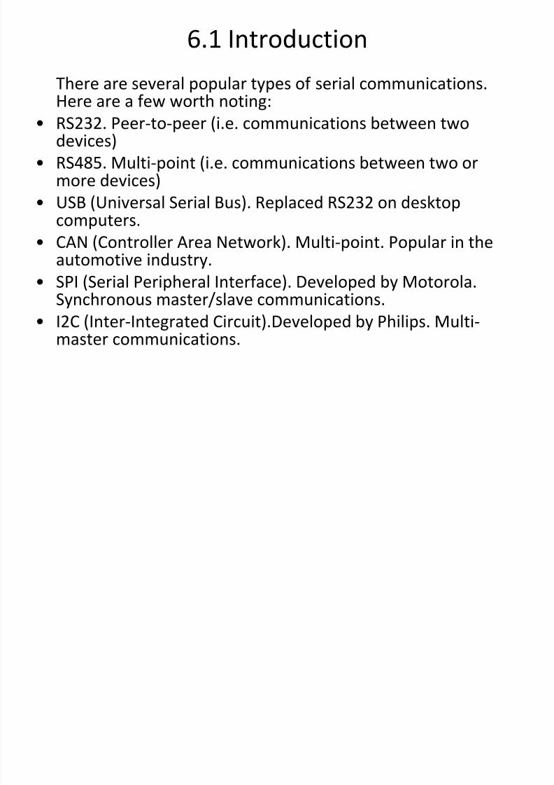
There are several popular types of serial communications.Here are a few worth noting:
• RS232. Peer-to-peer (i.e. communications between twodevices)
• RS485. Multi-point (i.e. communications between two ormore devices)
• USB (Universal Serial Bus). Replaced RS232 on desktopcomputers.
• CAN (Controller Area Network). Multi-point. Popular in theautomotive industry.
• SPI (Serial Peripheral Interface). Developed by Motorola.Synchronous master/slave communications.
• I2C (Inter-Integrated Circuit).Developed by Philips. Multi-master communications.
8/13/2019 Serial Communication 2
http://slidepdf.com/reader/full/serial-communication-2 4/31
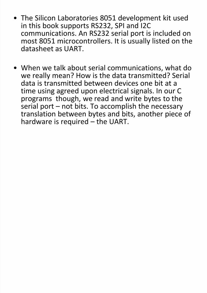
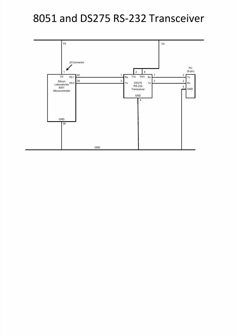
• The Silicon Laboratories 8051 development kit usedin this book supports RS232, SPI and I2C
communications. An RS232 serial port is included onmost 8051 microcontrollers. It is usually listed on thedatasheet as UART.
• When we talk about serial communications, what dowe really mean? How is the data transmitted? Serialdata is transmitted between devices one bit at atime using agreed upon electrical signals. In our Cprograms though, we read and write bytes to the
serial port – not bits. To accomplish the necessarytranslation between bytes and bits, another piece ofhardware is required – the UART.
8/13/2019 Serial Communication 2
http://slidepdf.com/reader/full/serial-communication-2 5/31
6.2 UARTs and Transceivers
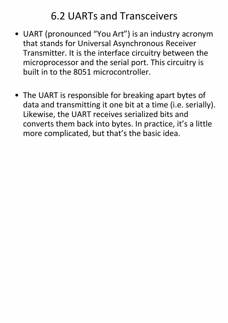
• UART (pronounced “You Art”) is an industry acronymthat stands for Universal Asynchronous ReceiverTransmitter. It is the interface circuitry between themicroprocessor and the serial port. This circuitry isbuilt in to the 8051 microcontroller.
• The UART is responsible for breaking apart bytes ofdata and transmitting it one bit at a time (i.e. serially).Likewise, the UART receives serialized bits andconverts them back into bytes. In practice, it’s a littlemore complicated, but that’s the basic idea.
8/13/2019 Serial Communication 2
http://slidepdf.com/reader/full/serial-communication-2 6/31
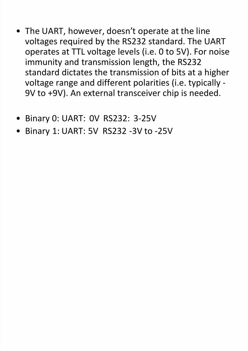
• The UART, however, doesn’t operate at the line
voltages required by the RS232 standard. The UARToperates at TTL voltage levels (i.e. 0 to 5V). For noiseimmunity and transmission length, the RS232standard dictates the transmission of bits at a higher
voltage range and different polarities (i.e. typically -9V to +9V). An external transceiver chip is needed.
• Binary 0: UART: 0V RS232: 3-25V
• Binary 1: UART: 5V RS232 -3V to -25V
8/13/2019 Serial Communication 2
http://slidepdf.com/reader/full/serial-communication-2 7/31
8051 and DS275 RS-232 Transceiver
Vd
J2 Connector
P0.1
P0.0
42
39
Vd
1
Silicon
Laboratories
8051
Microcontroller
GND
39
Rx1
Tx3
Rx
Tx
7
5
Vcc
2 8
GND
4
Vdrv
DS275RS-232
Transceiver
GND
Vd
Tx3
Rx2
5GND
PC
(9-pin)
8/13/2019 Serial Communication 2
http://slidepdf.com/reader/full/serial-communication-2 8/31
• UART communications is asynchronous (i.e. notsynchronous). This means that there is no master
clock used for timing data transfer between devices.• The UART is also responsible for baud rate
generation. This determines the speed at which datais transmitted and received. One baud is one bit per
second (bps). As of this writing, data rates can reachup to 230,400 baud. The cable length betweendevices is limited by the baud rate -- the higher thespeed, the shorter the cable. The RS-232C standardonly permits transmission speeds up to 19200 baudwith a cable length of 45 feet. With modern UARTs,230,400 baud can be achieved with a short cablelength of a few feet.
8/13/2019 Serial Communication 2
http://slidepdf.com/reader/full/serial-communication-2 9/31
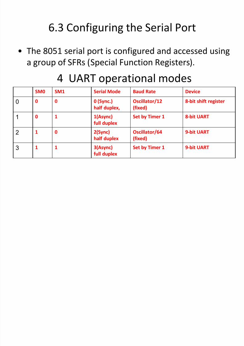
6.3 Configuring the Serial Port
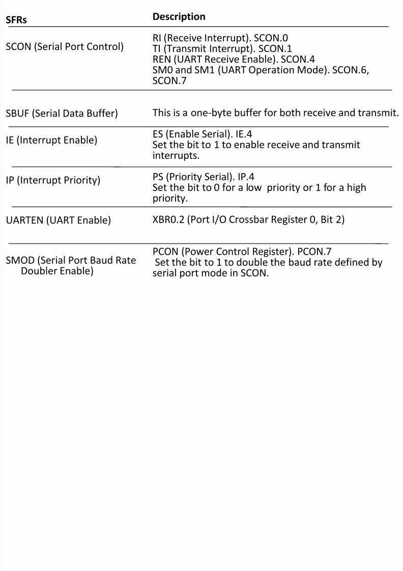
• The 8051 serial port is configured and accessed using
a group of SFRs (Special Function Registers).
4 UART operational modesSM0 SM1 Serial Mode Baud Rate Device
0 0 0 0 (Sync.)
half duplex,
Oscillator/12
(fixed)
8-bit shift register
1 0 1 1(Async)
full duplex
Set by Timer 1 8-bit UART
2 1 0 2(Sync)
half duplex
Oscillator/64
(fixed)
9-bit UART
3 1 1 3(Async)
full duplex
Set by Timer 1 9-bit UART
8/13/2019 Serial Communication 2
http://slidepdf.com/reader/full/serial-communication-2 10/31
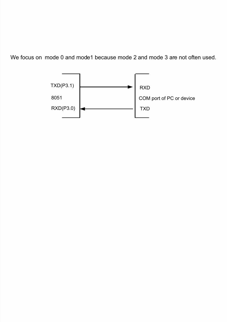
We focus on mode 0 and mode1 because mode 2 and mode 3 are not often used.
TXD(P3.1)
RXD(P3.0)
RXD
TXD
COM port of PC or device8051
8/13/2019 Serial Communication 2
http://slidepdf.com/reader/full/serial-communication-2 11/31
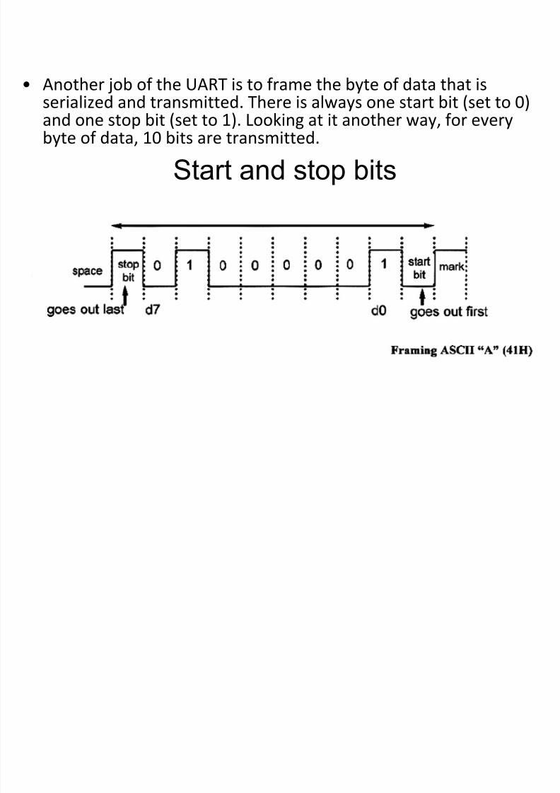
• Another job of the UART is to frame the byte of data that is
serialized and transmitted. There is always one start bit (set to 0)and one stop bit (set to 1). Looking at it another way, for everybyte of data, 10 bits are transmitted.
Start and stop bits
8/13/2019 Serial Communication 2
http://slidepdf.com/reader/full/serial-communication-2 12/31
8/13/2019 Serial Communication 2
http://slidepdf.com/reader/full/serial-communication-2 13/31
SFRs
SCON (Serial Port Control)
SBUF (Serial Data Buffer)
IE (Interrupt Enable)
IP (Interrupt Priority)
UARTEN (UART Enable)
SMOD (Serial Port Baud RateDoubler Enable)
Description
RI (Receive Interrupt). SCON.0TI (Transmit Interrupt). SCON.1REN (UART Receive Enable). SCON.4
SM0 and SM1 (UART Operation Mode). SCON.6,SCON.7
This is a one-byte buffer for both receive and transmit.
ES (Enable Serial). IE.4Set the bit to 1 to enable receive and transmitinterrupts.
PS (Priority Serial). IP.4Set the bit to 0 for a low priority or 1 for a highpriority.
XBR0.2 (Port I/O Crossbar Register 0, Bit 2)
PCON (Power Control Register). PCON.7Set the bit to 1 to double the baud rate defined byserial port mode in SCON.
8/13/2019 Serial Communication 2
http://slidepdf.com/reader/full/serial-communication-2 14/31
6.4 Setting the Baud Rate
The baud rate is a combination of factors:
• UART mode.
• The crystal frequency.
• The number of ticks required by the 8051 tocomplete a simple instruction. This varies from 1 to12. For the 8051 microcontroller used in this book,the value is 1.
• The setting of the SMOD bit (i.e. normal or doublebaud rate).
• The reload value for the Timer.
8/13/2019 Serial Communication 2
http://slidepdf.com/reader/full/serial-communication-2 15/31
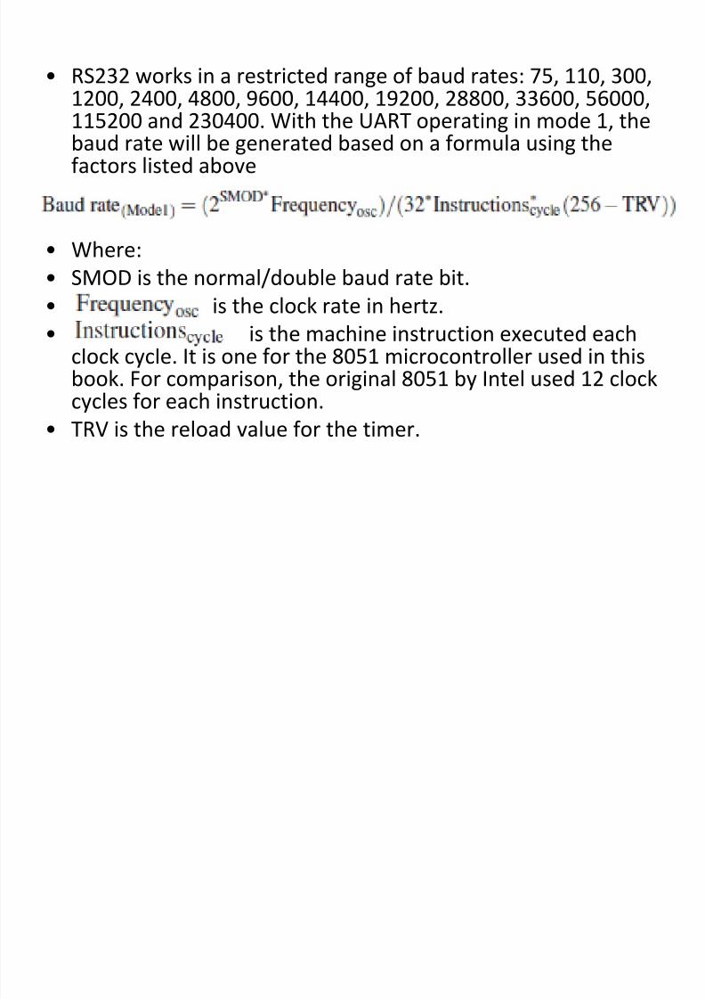
• RS232 works in a restricted range of baud rates: 75, 110, 300,1200, 2400, 4800, 9600, 14400, 19200, 28800, 33600, 56000,
115200 and 230400. With the UART operating in mode 1, thebaud rate will be generated based on a formula using thefactors listed above
• Where:• SMOD is the normal/double baud rate bit.
• is the clock rate in hertz.
• is the machine instruction executed eachclock cycle. It is one for the 8051 microcontroller used in thisbook. For comparison, the original 8051 by Intel used 12 clockcycles for each instruction.
• TRV is the reload value for the timer.
8/13/2019 Serial Communication 2
http://slidepdf.com/reader/full/serial-communication-2 16/31
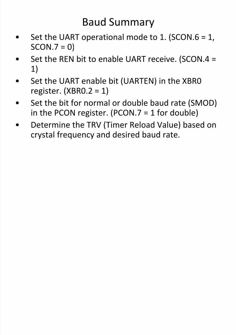
Baud Summary
• Set the UART operational mode to 1. (SCON.6 = 1,SCON.7 = 0)
• Set the REN bit to enable UART receive. (SCON.4 =1)
• Set the UART enable bit (UARTEN) in the XBR0register. (XBR0.2 = 1)
• Set the bit for normal or double baud rate (SMOD)in the PCON register. (PCON.7 = 1 for double)
• Determine the TRV (Timer Reload Value) based oncrystal frequency and desired baud rate.
8/13/2019 Serial Communication 2
http://slidepdf.com/reader/full/serial-communication-2 17/31
8/13/2019 Serial Communication 2
http://slidepdf.com/reader/full/serial-communication-2 18/31
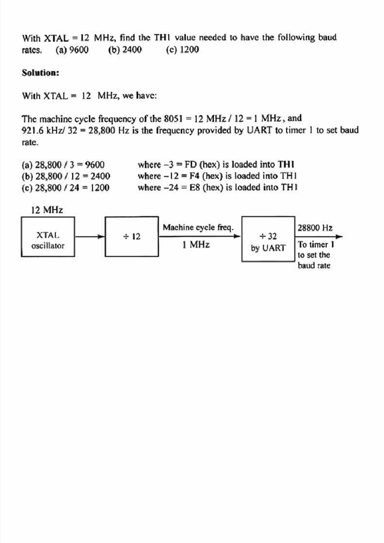
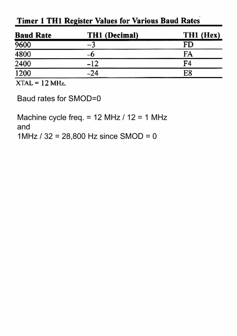
Baud rates for SMOD=0
Machine cycle freq. = 12 MHz / 12 = 1 MHz
and1MHz / 32 = 28,800 Hz since SMOD = 0
8/13/2019 Serial Communication 2
http://slidepdf.com/reader/full/serial-communication-2 19/31
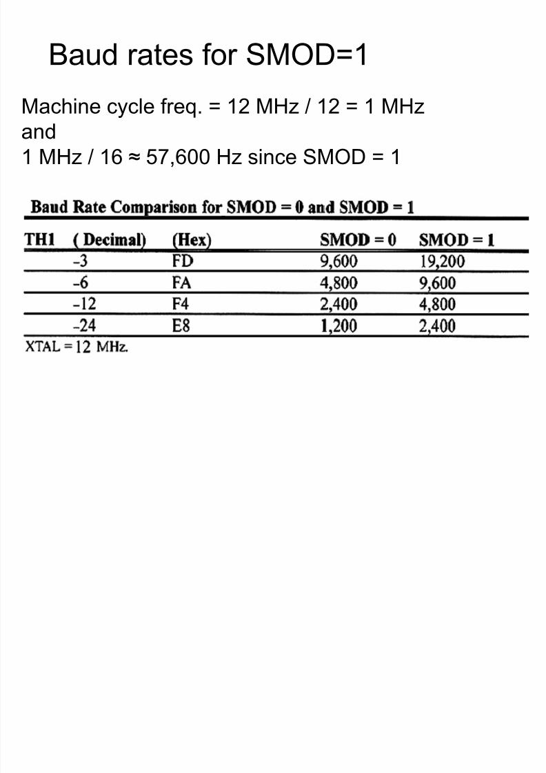
Baud rates for SMOD=1
Machine cycle freq. = 12 MHz / 12 = 1 MHz
and
1 MHz / 16 ≈ 57,600 Hz since SMOD = 1
8/13/2019 Serial Communication 2
http://slidepdf.com/reader/full/serial-communication-2 20/31
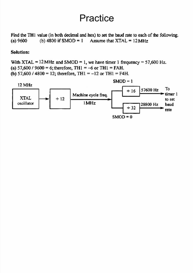
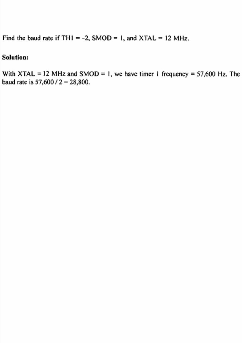
Practice
8/13/2019 Serial Communication 2
http://slidepdf.com/reader/full/serial-communication-2 21/31
8/13/2019 Serial Communication 2
http://slidepdf.com/reader/full/serial-communication-2 22/31
6.5 Reading and Writing
• After all that we went through to configure the port,reading and writing bytes is easy. We simply readfrom and write to the SBUF register. For example:
• inByte = SBUF; // Read a character from the UART
• SBUF = outByte; // Write a character to the UART• The register SBUF is used for both reading and
writing bytes. Internally, there are two separateregisters. They are both represented as SBUF for the
convenience of the programmer.
8/13/2019 Serial Communication 2
http://slidepdf.com/reader/full/serial-communication-2 23/31
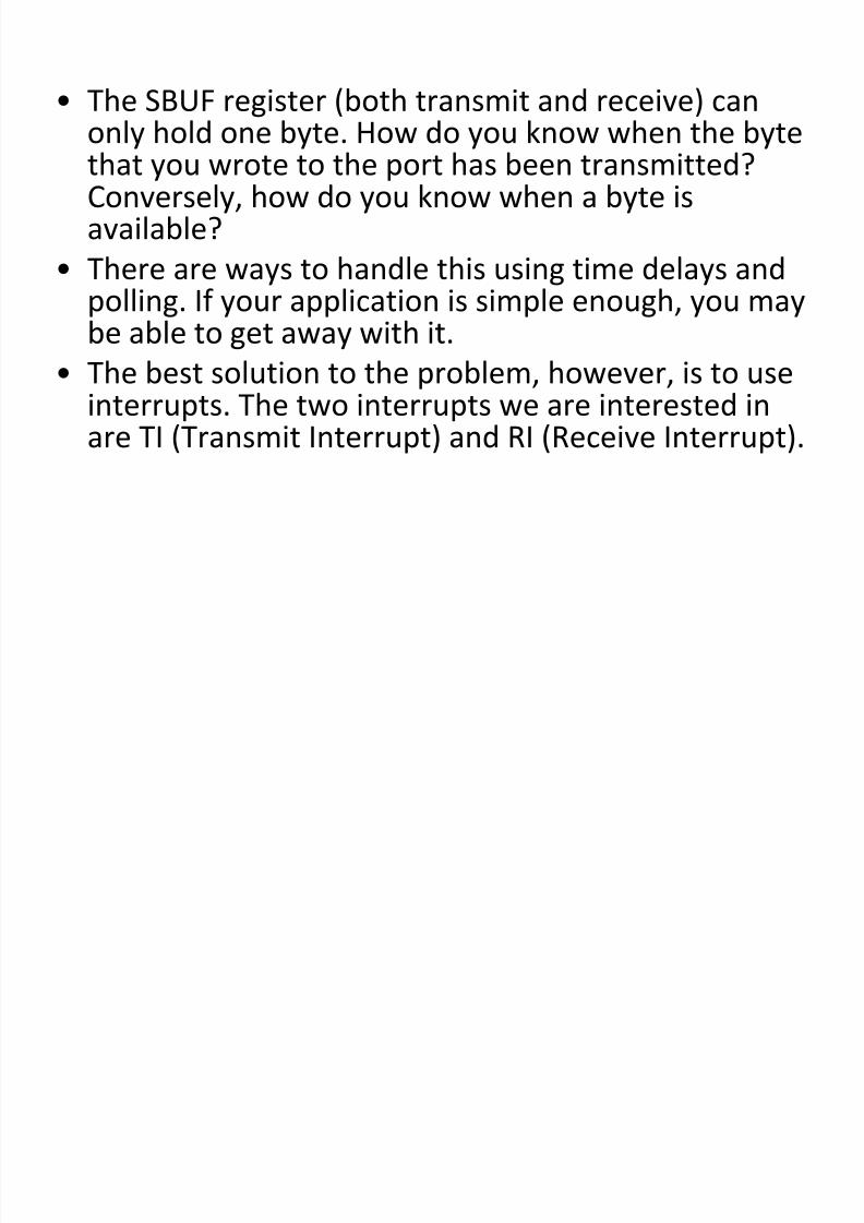
• The SBUF register (both transmit and receive) canonly hold one byte. How do you know when the bytethat you wrote to the port has been transmitted?Conversely, how do you know when a byte isavailable?
• There are ways to handle this using time delays and
polling. If your application is simple enough, you maybe able to get away with it.
• The best solution to the problem, however, is to useinterrupts. The two interrupts we are interested inare TI (Transmit Interrupt) and RI (Receive Interrupt).
8/13/2019 Serial Communication 2
http://slidepdf.com/reader/full/serial-communication-2 24/31
6.6 Handshaking
• The 8051 only has a one-byte buffer – SBUF. Incontrast, a typical PC serial port with a UART with 16-byte buffer.
• If SBUF is not serviced “quickly” enough, an incoming
byte may overwrite a byte that has not yet beenread and processed. Using a control technique calledhandshaking, it is possible to get the transmittingdevice to stop sending bytes until the 8051 is ready.
• Likewise, the 8051 can be signaled by the receivingdevice to stop transmitting. There are two forms ofhandshaking – software and hardware.
8/13/2019 Serial Communication 2
http://slidepdf.com/reader/full/serial-communication-2 25/31
• Software handshaking (also called XON/XOFF) uses controlcharacters in the byte stream to signal the halting andresuming of data transmission. Control-S (ASCII 19) signals theother device to stop sending data. Control-Q (ASCII 17) signalsthe other device to resume sending data. The disadvantagewith this approach is that the response time is slower and twocharacters in the ASCII character set must be reserved for
handshaking use.• Hardware handshaking uses additional I/O lines. The most
common form of hardware handshaking is to use twoadditional control wires called RTS (Ready to Send) and CTS(Clear to Send). One line is controlled by each device. The line
(either RTS or CTS) is asserted when bytes can be receivedand unasserted otherwise. These two handshaking lines areused to prevent buffer overruns.
8/13/2019 Serial Communication 2
http://slidepdf.com/reader/full/serial-communication-2 26/31
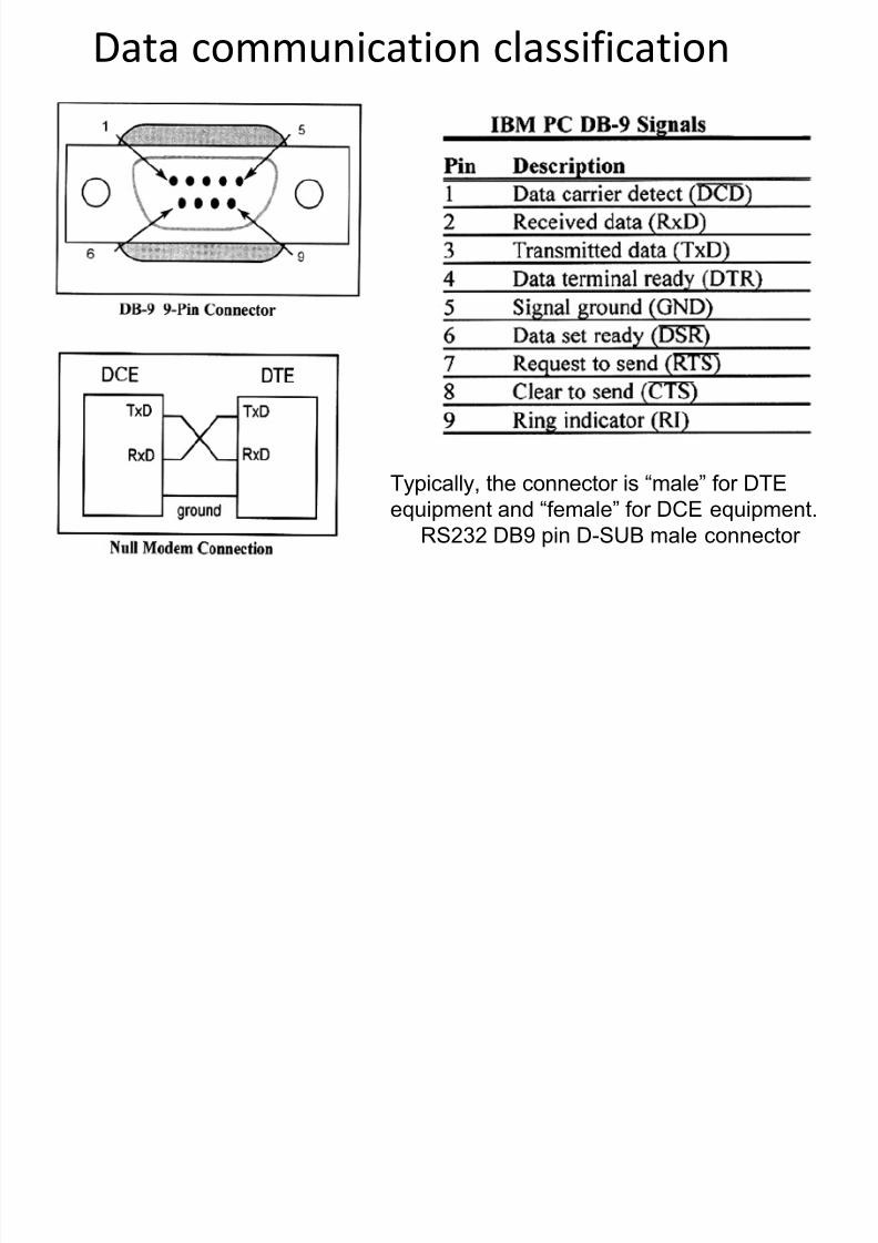
Data communication classification
Typically, the connector is “male” for DTE
equipment and “female” for DCE equipment.
RS232 DB9 pin D-SUB male connector
8/13/2019 Serial Communication 2
http://slidepdf.com/reader/full/serial-communication-2 27/31
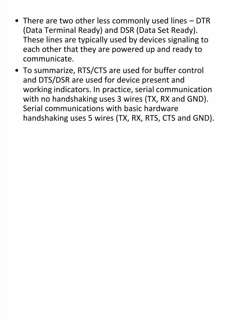
• There are two other less commonly used lines – DTR(Data Terminal Ready) and DSR (Data Set Ready).
These lines are typically used by devices signaling toeach other that they are powered up and ready tocommunicate.
• To summarize, RTS/CTS are used for buffer control
and DTS/DSR are used for device present andworking indicators. In practice, serial communicationwith no handshaking uses 3 wires (TX, RX and GND).Serial communications with basic hardware
handshaking uses 5 wires (TX, RX, RTS, CTS and GND).
8/13/2019 Serial Communication 2
http://slidepdf.com/reader/full/serial-communication-2 28/31
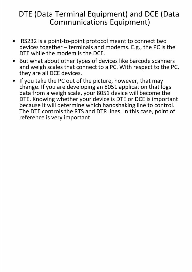
DTE (Data Terminal Equipment) and DCE (DataCommunications Equipment)
• RS232 is a point-to-point protocol meant to connect twodevices together – terminals and modems. E.g., the PC is theDTE while the modem is the DCE.
• But what about other types of devices like barcode scanners
and weigh scales that connect to a PC. With respect to the PC,they are all DCE devices.
• If you take the PC out of the picture, however, that maychange. If you are developing an 8051 application that logsdata from a weigh scale, your 8051 device will become the
DTE. Knowing whether your device is DTE or DCE is importantbecause it will determine which handshaking line to control.The DTE controls the RTS and DTR lines. In this case, point ofreference is very important.
8/13/2019 Serial Communication 2
http://slidepdf.com/reader/full/serial-communication-2 29/31
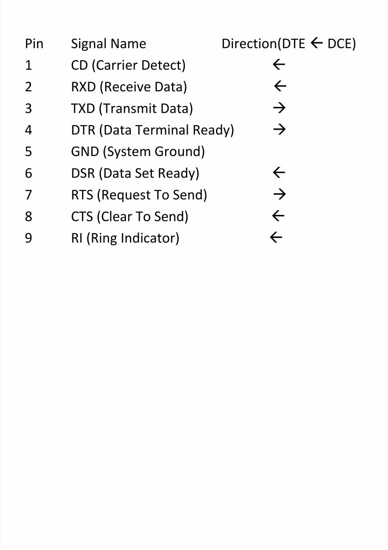
Pin Signal Name Direction(DTE DCE)
1 CD (Carrier Detect)
2 RXD (Receive Data)
3 TXD (Transmit Data)
4 DTR (Data Terminal Ready)
5 GND (System Ground)
6 DSR (Data Set Ready)
7 RTS (Request To Send)
8 CTS (Clear To Send)
9 RI (Ring Indicator)
8/13/2019 Serial Communication 2
http://slidepdf.com/reader/full/serial-communication-2 30/31
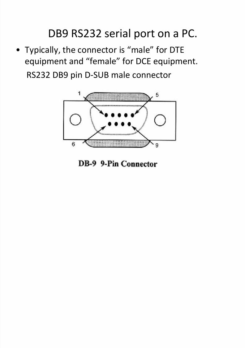
DB9 RS232 serial port on a PC.
• Typically, the connector is “male” for DTE
equipment and “female” for DCE equipment.
RS232 DB9 pin D-SUB male connector
8/13/2019 Serial Communication 2
http://slidepdf.com/reader/full/serial-communication-2 31/31
6.8 Summary
• This chapter introduced the RS232 serialcommunications standard and placed it in contextwith newer forms of serial communications. It alsodiscussed the role of the UART and externaltransceiver circuits necessary to transmit bits of data
at the proper voltage.• On the software side, this chapter discussed how toconfigure the serial port using the special functionregisters and also discussed issues pertaining tobaud rate generation. Finally, reading and writing to
the serial port was addressed and both software andhardware handshaking concepts were introduced.