Embed Size (px)
Citation preview
1Visit Cisco Connection Online at www.cisco.com
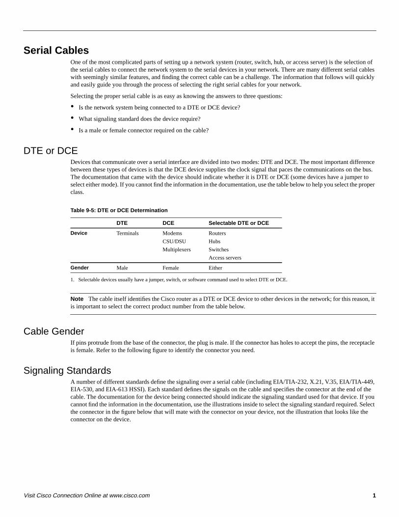
Serial CablesOne of the most complicated parts of setting up a network system (router, switch, hub, or access server) is the selection ofthe serial cables to connect the network system to the serial devices in your network. There are many different serial cableswith seemingly similar features, and finding the correct cable can be a challenge. The information that follows will quicklyand easily guide you through the process of selecting the right serial cables for your network.
Selecting the proper serial cable is as easy as knowing the answers to three questions:
• Is the network system being connected to a DTE or DCE device?
• What signaling standard does the device require?
• Is a male or female connector required on the cable?
DTE or DCEDevices that communicate over a serial interface are divided into two modes: DTE and DCE. The most important differencebetween these types of devices is that the DCE device supplies the clock signal that paces the communications on the bus.The documentation that came with the device should indicate whether it is DTE or DCE (some devices have a jumper toselect either mode). If you cannot find the information in the documentation, use the table below to help you select the properclass.
Table 9-5: DTE or DCE Determination
1. Selectable devices usually have a jumper, switch, or software command used to select DTE or DCE.
Note The cable itself identifies the Cisco router as a DTE or DCE device to other devices in the network; for this reason, itis important to select the correct product number from the table below.
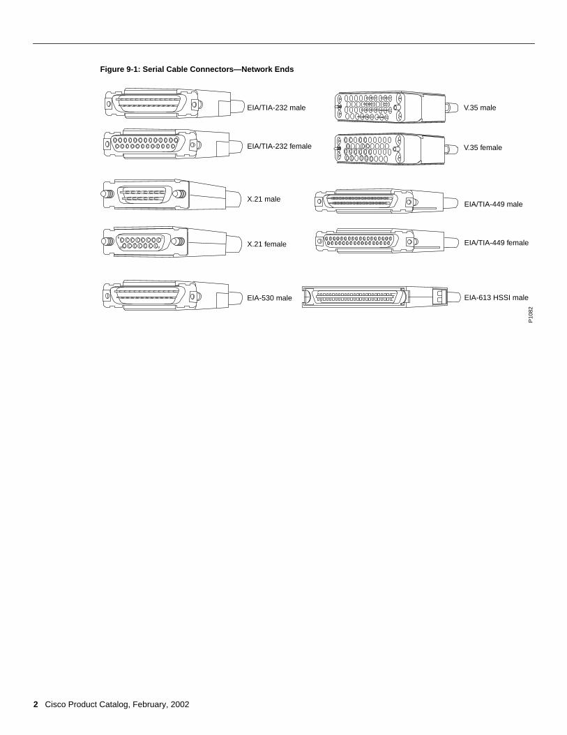
Cable GenderIf pins protrude from the base of the connector, the plug is male. If the connector has holes to accept the pins, the receptacleis female. Refer to the following figure to identify the connector you need.
Signaling StandardsA number of different standards define the signaling over a serial cable (including EIA/TIA-232, X.21, V.35, EIA/TIA-449,EIA-530, and EIA-613 HSSI). Each standard defines the signals on the cable and specifies the connector at the end of thecable. The documentation for the device being connected should indicate the signaling standard used for that device. If youcannot find the information in the documentation, use the illustrations inside to select the signaling standard required. Selectthe connector in the figure below that will mate with the connector on your device, not the illustration that looks like theconnector on the device.
DTE DCE Selectable DTE or DCE
Device Terminals Modems
CSU/DSU
Multiplexers
Routers
Hubs
Switches
Access servers
Gender Male Female Either
2 Cisco Product Catalog, February, 2002
Figure 9-1: Serial Cable Connectors—Network Ends
18
15 9
EIA/TIA-232 male
EIA/TIA-232 female
X.21 male
X.21 female
EIA-530 male
V.35 male
V.35 female
EIA/TIA-449 male
EIA/TIA-449 female
EIA-613 HSSI male
P10
82
3Visit Cisco Connection Online at www.cisco.com
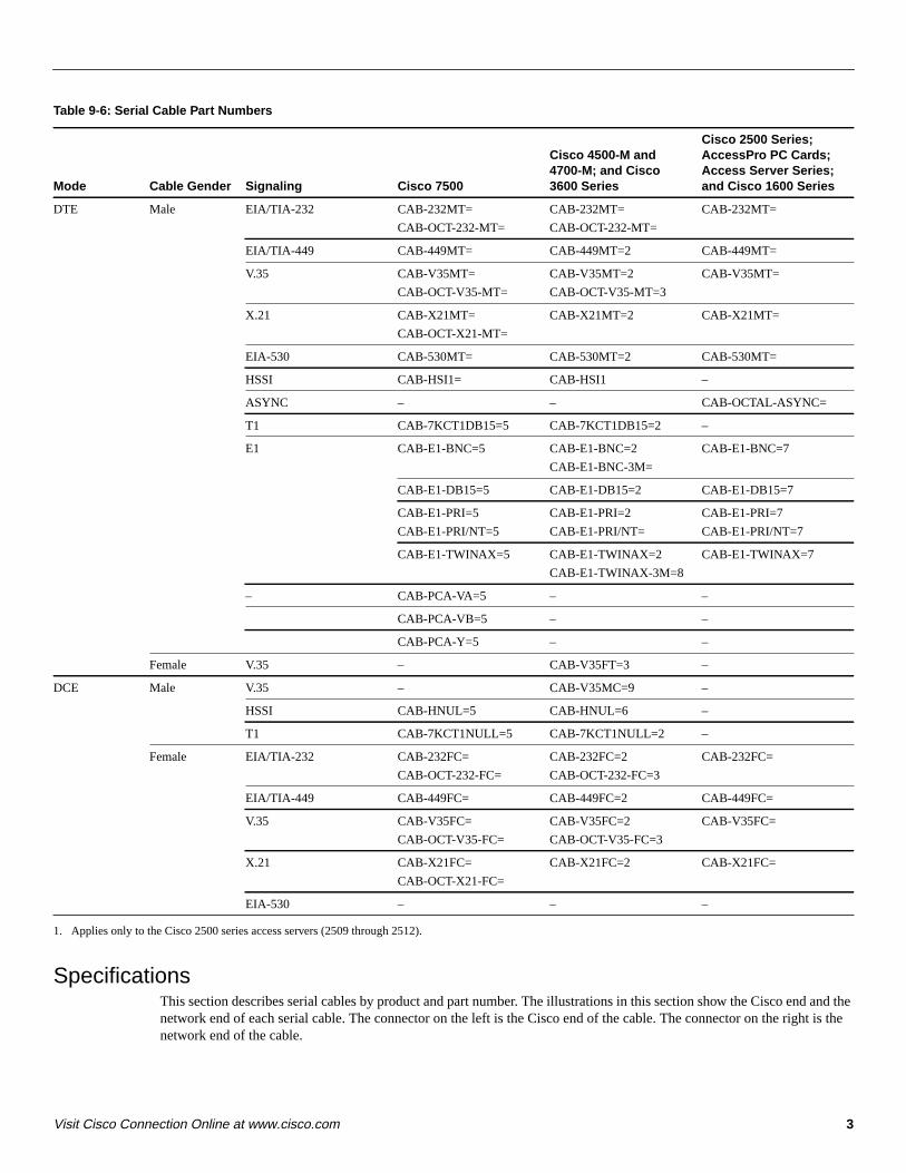
Table 9-6: Serial Cable Part Numbers
1. Applies only to the Cisco 2500 series access servers (2509 through 2512).
SpecificationsThis section describes serial cables by product and part number. The illustrations in this section show the Cisco end and thenetwork end of each serial cable. The connector on the left is the Cisco end of the cable. The connector on the right is thenetwork end of the cable.
Mode Cable Gender Signaling Cisco 7500
Cisco 4500-M and4700-M; and Cisco3600 Series
Cisco 2500 Series;AccessPro PC Cards;Access Server Series;and Cisco 1600 Series
DTE Male EIA/TIA-232 CAB-232MT=
CAB-OCT-232-MT=
CAB-232MT=
CAB-OCT-232-MT=
CAB-232MT=
EIA/TIA-449 CAB-449MT= CAB-449MT=2 CAB-449MT=
V.35 CAB-V35MT=
CAB-OCT-V35-MT=
CAB-V35MT=2
CAB-OCT-V35-MT=3
CAB-V35MT=
X.21 CAB-X21MT=
CAB-OCT-X21-MT=
CAB-X21MT=2 CAB-X21MT=
EIA-530 CAB-530MT= CAB-530MT=2 CAB-530MT=
HSSI CAB-HSI1= CAB-HSI1 –
ASYNC – – CAB-OCTAL-ASYNC=
T1 CAB-7KCT1DB15=5 CAB-7KCT1DB15=2 –
E1 CAB-E1-BNC=5 CAB-E1-BNC=2
CAB-E1-BNC-3M=
CAB-E1-BNC=7
CAB-E1-DB15=5 CAB-E1-DB15=2 CAB-E1-DB15=7
CAB-E1-PRI=5
CAB-E1-PRI/NT=5
CAB-E1-PRI=2
CAB-E1-PRI/NT=
CAB-E1-PRI=7
CAB-E1-PRI/NT=7
CAB-E1-TWINAX=5 CAB-E1-TWINAX=2
CAB-E1-TWINAX-3M=8
CAB-E1-TWINAX=7
– CAB-PCA-VA=5 – –
CAB-PCA-VB=5 – –
CAB-PCA-Y=5 – –
Female V.35 – CAB-V35FT=3 –
DCE Male V.35 – CAB-V35MC=9 –
HSSI CAB-HNUL=5 CAB-HNUL=6 –
T1 CAB-7KCT1NULL=5 CAB-7KCT1NULL=2 –
Female EIA/TIA-232 CAB-232FC=
CAB-OCT-232-FC=
CAB-232FC=2
CAB-OCT-232-FC=3
CAB-232FC=
EIA/TIA-449 CAB-449FC= CAB-449FC=2 CAB-449FC=
V.35 CAB-V35FC=
CAB-OCT-V35-FC=
CAB-V35FC=2
CAB-OCT-V35-FC=3
CAB-V35FC=
X.21 CAB-X21FC=
CAB-OCT-X21-FC=
CAB-X21FC=2 CAB-X21FC=
EIA-530 – – –
4 Cisco Product Catalog, February, 2002
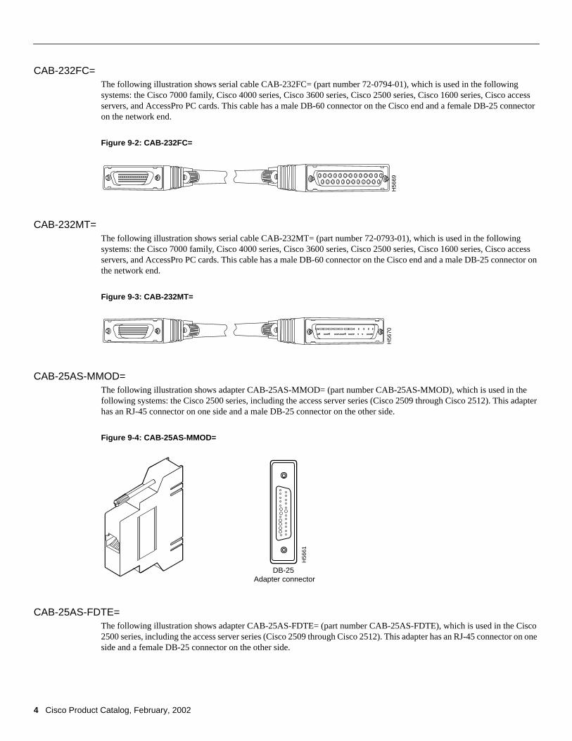
CAB-232FC=The following illustration shows serial cable CAB-232FC= (part number 72-0794-01), which is used in the followingsystems: the Cisco 7000 family, Cisco 4000 series, Cisco 3600 series, Cisco 2500 series, Cisco 1600 series, Cisco accessservers, and AccessPro PC cards. This cable has a male DB-60 connector on the Cisco end and a female DB-25 connectoron the network end.
Figure 9-2: CAB-232FC=
CAB-232MT=The following illustration shows serial cable CAB-232MT= (part number 72-0793-01), which is used in the followingsystems: the Cisco 7000 family, Cisco 4000 series, Cisco 3600 series, Cisco 2500 series, Cisco 1600 series, Cisco accessservers, and AccessPro PC cards. This cable has a male DB-60 connector on the Cisco end and a male DB-25 connector onthe network end.
Figure 9-3: CAB-232MT=
CAB-25AS-MMOD=The following illustration shows adapter CAB-25AS-MMOD= (part number CAB-25AS-MMOD), which is used in thefollowing systems: the Cisco 2500 series, including the access server series (Cisco 2509 through Cisco 2512). This adapterhas an RJ-45 connector on one side and a male DB-25 connector on the other side.
Figure 9-4: CAB-25AS-MMOD=
CAB-25AS-FDTE=The following illustration shows adapter CAB-25AS-FDTE= (part number CAB-25AS-FDTE), which is used in the Cisco2500 series, including the access server series (Cisco 2509 through Cisco 2512). This adapter has an RJ-45 connector on oneside and a female DB-25 connector on the other side.
H56
69H
5670
H56
61
DB-25 Adapter connector

5Visit Cisco Connection Online at www.cisco.com
Figure 9-5: CAB-25AS-FDTE=
CAB-449FC=The following illustration shows serial cable CAB-449FC= (part number 72-0796-01), which is used in the followingsystems: the Cisco 7000 family, Cisco 4000 series, Cisco 3600 series, Cisco 2500 series, Cisco 1600 series, Cisco accessservers, and AccessPro PC cards. This cable has a male DB-60 connector on the Cisco end and a female DB-37 connectoron the network end.
Figure 9-6: CAB-449FC
CAB-449MT=The following illustration shows serial cable CAB-449MT= (part number 72-0795-01), which is used in the followingsystems: the Cisco 7000 family, Cisco 4000 series, Cisco 3600 series, Cisco 2500 series, Cisco 1600 series, Cisco accessservers, and AccessPro PC cards. This cable has a male DB-60 connector on the Cisco end and a male DB-37 connector onthe network end.
Figure 9-7: CAB-449MT=
CAB-500RJ=The following illustration shows serial cable CAB-500RJ= (part number 31-0590-01), which is used in the followingsystems: the Cisco 2500 series and the Cisco CS500. This cable has an RJ-45 connector on both ends.
Figure 9-8: CAB-500RJ=
H57
66
DB-25 Adapter connector
H56
80H
5681
H56
86
6 Cisco Product Catalog, February, 2002
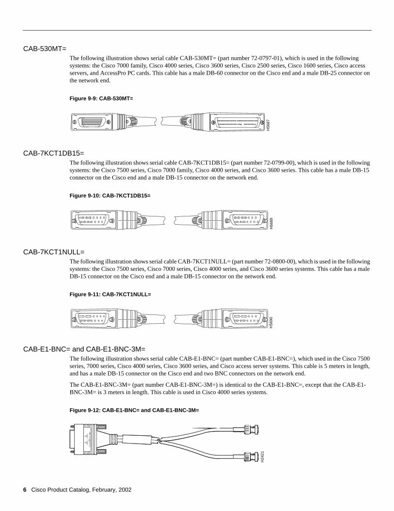
CAB-530MT=The following illustration shows serial cable CAB-530MT= (part number 72-0797-01), which is used in the followingsystems: the Cisco 7000 family, Cisco 4000 series, Cisco 3600 series, Cisco 2500 series, Cisco 1600 series, Cisco accessservers, and AccessPro PC cards. This cable has a male DB-60 connector on the Cisco end and a male DB-25 connector onthe network end.
Figure 9-9: CAB-530MT=
CAB-7KCT1DB15=The following illustration shows serial cable CAB-7KCT1DB15= (part number 72-0799-00), which is used in the followingsystems: the Cisco 7500 series, Cisco 7000 family, Cisco 4000 series, and Cisco 3600 series. This cable has a male DB-15connector on the Cisco end and a male DB-15 connector on the network end.
Figure 9-10: CAB-7KCT1DB15=
CAB-7KCT1NULL=The following illustration shows serial cable CAB-7KCT1NULL= (part number 72-0800-00), which is used in the followingsystems: the Cisco 7500 series, Cisco 7000 series, Cisco 4000 series, and Cisco 3600 series systems. This cable has a maleDB-15 connector on the Cisco end and a male DB-15 connector on the network end.
Figure 9-11: CAB-7KCT1NULL=
CAB-E1-BNC= and CAB-E1-BNC-3M=The following illustration shows serial cable CAB-E1-BNC= (part number CAB-E1-BNC=), which used in the Cisco 7500series, 7000 series, Cisco 4000 series, Cisco 3600 series, and Cisco access server systems. This cable is 5 meters in length,and has a male DB-15 connector on the Cisco end and two BNC connectors on the network end.
The CAB-E1-BNC-3M= (part number CAB-E1-BNC-3M=) is identical to the CAB-E1-BNC=, except that the CAB-E1-BNC-3M= is 3 meters in length. This cable is used in Cisco 4000 series systems.
Figure 9-12: CAB-E1-BNC= and CAB-E1-BNC-3M=
H56
87H
5689
H56
90
H24
21
7Visit Cisco Connection Online at www.cisco.com
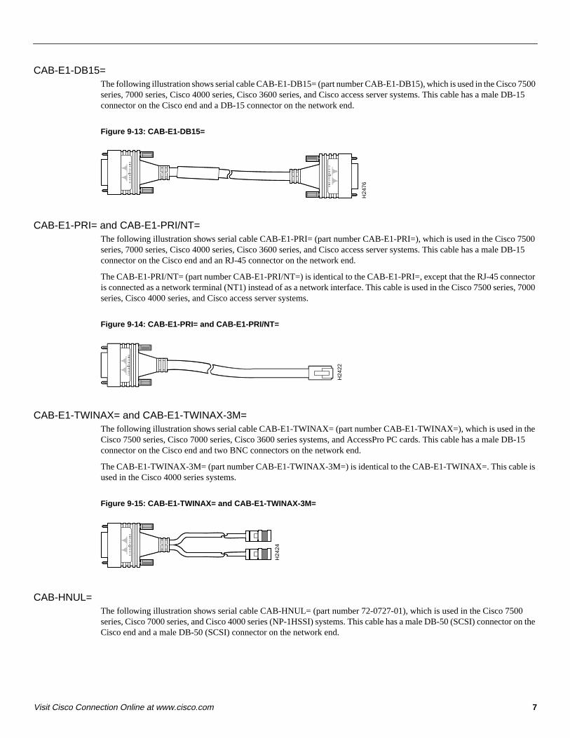
CAB-E1-DB15=The following illustration shows serial cable CAB-E1-DB15= (part number CAB-E1-DB15), which is used in the Cisco 7500series, 7000 series, Cisco 4000 series, Cisco 3600 series, and Cisco access server systems. This cable has a male DB-15connector on the Cisco end and a DB-15 connector on the network end.
Figure 9-13: CAB-E1-DB15=
CAB-E1-PRI= and CAB-E1-PRI/NT=The following illustration shows serial cable CAB-E1-PRI= (part number CAB-E1-PRI=), which is used in the Cisco 7500series, 7000 series, Cisco 4000 series, Cisco 3600 series, and Cisco access server systems. This cable has a male DB-15connector on the Cisco end and an RJ-45 connector on the network end.
The CAB-E1-PRI/NT= (part number CAB-E1-PRI/NT=) is identical to the CAB-E1-PRI=, except that the RJ-45 connectoris connected as a network terminal (NT1) instead of as a network interface. This cable is used in the Cisco 7500 series, 7000series, Cisco 4000 series, and Cisco access server systems.
Figure 9-14: CAB-E1-PRI= and CAB-E1-PRI/NT=
CAB-E1-TWINAX= and CAB-E1-TWINAX-3M=The following illustration shows serial cable CAB-E1-TWINAX= (part number CAB-E1-TWINAX=), which is used in theCisco 7500 series, Cisco 7000 series, Cisco 3600 series systems, and AccessPro PC cards. This cable has a male DB-15connector on the Cisco end and two BNC connectors on the network end.
The CAB-E1-TWINAX-3M= (part number CAB-E1-TWINAX-3M=) is identical to the CAB-E1-TWINAX=. This cable isused in the Cisco 4000 series systems.
Figure 9-15: CAB-E1-TWINAX= and CAB-E1-TWINAX-3M=
CAB-HNUL=The following illustration shows serial cable CAB-HNUL= (part number 72-0727-01), which is used in the Cisco 7500series, Cisco 7000 series, and Cisco 4000 series (NP-1HSSI) systems. This cable has a male DB-50 (SCSI) connector on theCisco end and a male DB-50 (SCSI) connector on the network end.
H24
76
H24
22
H24
24
8 Cisco Product Catalog, February, 2002
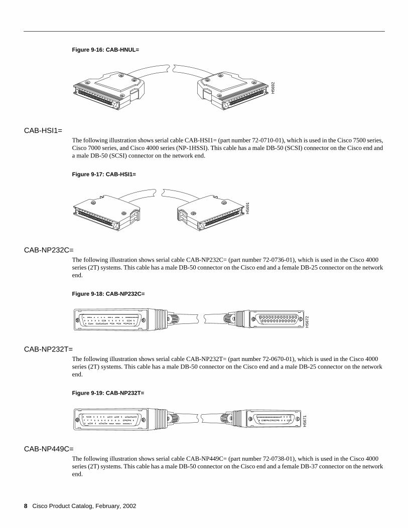
Figure 9-16: CAB-HNUL=
CAB-HSI1=The following illustration shows serial cable CAB-HSI1= (part number 72-0710-01), which is used in the Cisco 7500 series,Cisco 7000 series, and Cisco 4000 series (NP-1HSSI). This cable has a male DB-50 (SCSI) connector on the Cisco end anda male DB-50 (SCSI) connector on the network end.
Figure 9-17: CAB-HSI1=
CAB-NP232C=The following illustration shows serial cable CAB-NP232C= (part number 72-0736-01), which is used in the Cisco 4000series (2T) systems. This cable has a male DB-50 connector on the Cisco end and a female DB-25 connector on the networkend.
Figure 9-18: CAB-NP232C=
CAB-NP232T=The following illustration shows serial cable CAB-NP232T= (part number 72-0670-01), which is used in the Cisco 4000series (2T) systems. This cable has a male DB-50 connector on the Cisco end and a male DB-25 connector on the networkend.
Figure 9-19: CAB-NP232T=
CAB-NP449C=The following illustration shows serial cable CAB-NP449C= (part number 72-0738-01), which is used in the Cisco 4000series (2T) systems. This cable has a male DB-50 connector on the Cisco end and a female DB-37 connector on the networkend.
H56
92
H56
91
H56
72H
5671
9Visit Cisco Connection Online at www.cisco.com
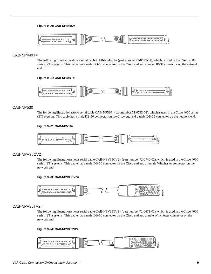
Figure 9-20: CAB-NP449C=
CAB-NP449T=The following illustration shows serial cable CAB-NP449T= (part number 72-0672-01), which is used in the Cisco 4000series (2T) systems. This cable has a male DB-50 connector on the Cisco end and a male DB-37 connector on the networkend.
Figure 9-21: CAB-NP449T=
CAB-NP530=The following illustration shows serial cable CAB-NP530= (part number 72-0732-01), which is used in the Cisco 4000 series(2T) systems. This cable has a male DB-50 connector on the Cisco end and a male DB-25 connector on the network end.
Figure 9-22: CAB-NP530=
CAB-NPV35CV2=The following illustration shows serial cable CAB-NPV35CV2= (part number 72-0740-02), which is used in the Cisco 4000series (2T) systems. This cable has a male DB-50 connector on the Cisco end and a female Winchester connector on thenetwork end.
Figure 9-23: CAB-NPV35CV2=
CAB-NPV35TV2=The following illustration shows serial cable CAB-NPV35TV2= (part number 72-0671-02), which is used in the Cisco 4000series (2T) systems. This cable has a male DB-50 connector on the Cisco end and a male Winchester connector on thenetwork end.
Figure 9-24: CAB-NPV35TV2=
H56
74H
5673
H56
58
H56
76
H56
77
10 Cisco Product Catalog, February, 2002
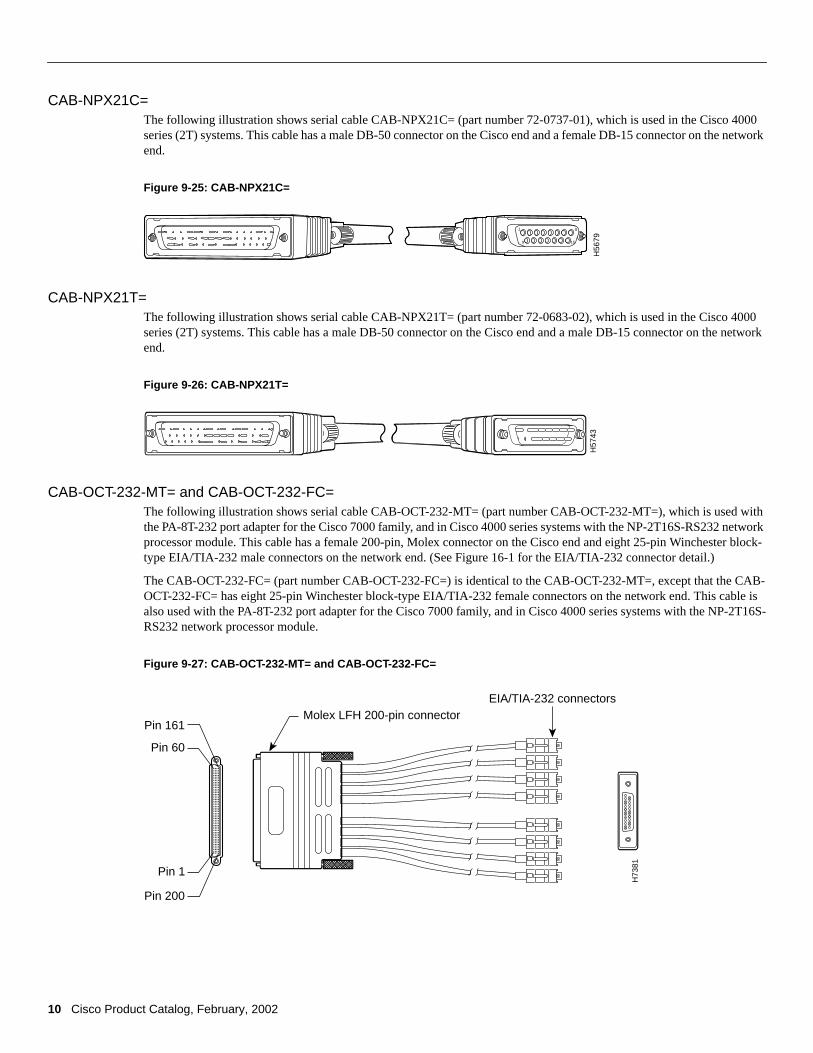
CAB-NPX21C=The following illustration shows serial cable CAB-NPX21C= (part number 72-0737-01), which is used in the Cisco 4000series (2T) systems. This cable has a male DB-50 connector on the Cisco end and a female DB-15 connector on the networkend.
Figure 9-25: CAB-NPX21C=
CAB-NPX21T=The following illustration shows serial cable CAB-NPX21T= (part number 72-0683-02), which is used in the Cisco 4000series (2T) systems. This cable has a male DB-50 connector on the Cisco end and a male DB-15 connector on the networkend.
Figure 9-26: CAB-NPX21T=
CAB-OCT-232-MT= and CAB-OCT-232-FC=The following illustration shows serial cable CAB-OCT-232-MT= (part number CAB-OCT-232-MT=), which is used withthe PA-8T-232 port adapter for the Cisco 7000 family, and in Cisco 4000 series systems with the NP-2T16S-RS232 networkprocessor module. This cable has a female 200-pin, Molex connector on the Cisco end and eight 25-pin Winchester block-type EIA/TIA-232 male connectors on the network end. (See Figure 16-1 for the EIA/TIA-232 connector detail.)
The CAB-OCT-232-FC= (part number CAB-OCT-232-FC=) is identical to the CAB-OCT-232-MT=, except that the CAB-OCT-232-FC= has eight 25-pin Winchester block-type EIA/TIA-232 female connectors on the network end. This cable isalso used with the PA-8T-232 port adapter for the Cisco 7000 family, and in Cisco 4000 series systems with the NP-2T16S-RS232 network processor module.
Figure 9-27: CAB-OCT-232-MT= and CAB-OCT-232-FC=
1 8
15 9
H56
79H
5743
EIA/TIA-232 connectors
H73
81
Pin 60
Pin 161
Pin 200
Pin 1
Molex LFH 200-pin connector
11Visit Cisco Connection Online at www.cisco.com
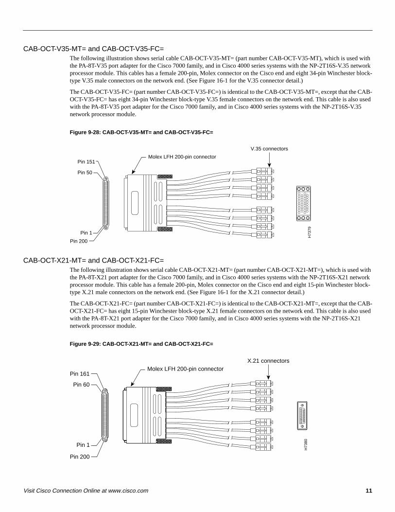
CAB-OCT-V35-MT= and CAB-OCT-V35-FC=The following illustration shows serial cable CAB-OCT-V35-MT= (part number CAB-OCT-V35-MT), which is used withthe PA-8T-V35 port adapter for the Cisco 7000 family, and in Cisco 4000 series systems with the NP-2T16S-V.35 networkprocessor module. This cables has a female 200-pin, Molex connector on the Cisco end and eight 34-pin Winchester block-type V.35 male connectors on the network end. (See Figure 16-1 for the V.35 connector detail.)
The CAB-OCT-V35-FC= (part number CAB-OCT-V35-FC=) is identical to the CAB-OCT-V35-MT=, except that the CAB-OCT-V35-FC= has eight 34-pin Winchester block-type V.35 female connectors on the network end. This cable is also usedwith the PA-8T-V35 port adapter for the Cisco 7000 family, and in Cisco 4000 series systems with the NP-2T16S-V.35network processor module.
Figure 9-28: CAB-OCT-V35-MT= and CAB-OCT-V35-FC=
CAB-OCT-X21-MT= and CAB-OCT-X21-FC=The following illustration shows serial cable CAB-OCT-X21-MT= (part number CAB-OCT-X21-MT=), which is used withthe PA-8T-X21 port adapter for the Cisco 7000 family, and in Cisco 4000 series systems with the NP-2T16S-X21 networkprocessor module. This cable has a female 200-pin, Molex connector on the Cisco end and eight 15-pin Winchester block-type X.21 male connectors on the network end. (See Figure 16-1 for the X.21 connector detail.)
The CAB-OCT-X21-FC= (part number CAB-OCT-X21-FC=) is identical to the CAB-OCT-X21-MT=, except that the CAB-OCT-X21-FC= has eight 15-pin Winchester block-type X.21 female connectors on the network end. This cable is also usedwith the PA-8T-X21 port adapter for the Cisco 7000 family, and in Cisco 4000 series systems with the NP-2T16S-X21network processor module.
Figure 9-29: CAB-OCT-X21-MT= and CAB-OCT-X21-FC=
Pin 50
Pin 151
Pin 1
Pin 200
Molex LFH 200-pin connector
V.35 connectors
H73
79
Pin 60
Pin 161
Pin 200
Pin 1
Molex LFH 200-pin connector X.21 connectors
H73
80
12 Cisco Product Catalog, February, 2002
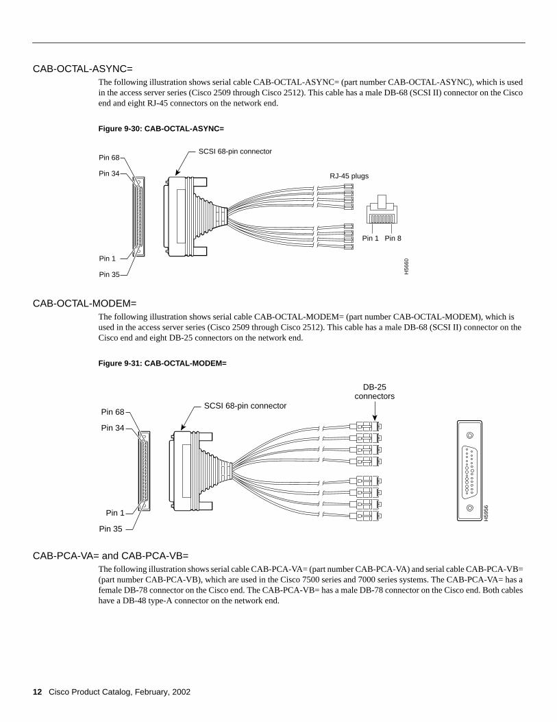
CAB-OCTAL-ASYNC=The following illustration shows serial cable CAB-OCTAL-ASYNC= (part number CAB-OCTAL-ASYNC), which is usedin the access server series (Cisco 2509 through Cisco 2512). This cable has a male DB-68 (SCSI II) connector on the Ciscoend and eight RJ-45 connectors on the network end.
Figure 9-30: CAB-OCTAL-ASYNC=
CAB-OCTAL-MODEM=The following illustration shows serial cable CAB-OCTAL-MODEM= (part number CAB-OCTAL-MODEM), which isused in the access server series (Cisco 2509 through Cisco 2512). This cable has a male DB-68 (SCSI II) connector on theCisco end and eight DB-25 connectors on the network end.
Figure 9-31: CAB-OCTAL-MODEM=
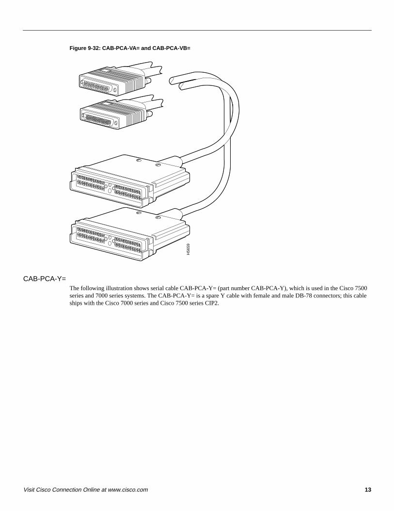
CAB-PCA-VA= and CAB-PCA-VB=The following illustration shows serial cable CAB-PCA-VA= (part number CAB-PCA-VA) and serial cable CAB-PCA-VB=(part number CAB-PCA-VB), which are used in the Cisco 7500 series and 7000 series systems. The CAB-PCA-VA= has afemale DB-78 connector on the Cisco end. The CAB-PCA-VB= has a male DB-78 connector on the Cisco end. Both cableshave a DB-48 type-A connector on the network end.
Pin 68
Pin 34
Pin 1
Pin 35
SCSI 68-pin connector
Pin 1 Pin 8
RJ-45 plugs
H56
60Pin 68
Pin 34
Pin 1
Pin 35
SCSI 68-pin connector
DB-25connectors
H59
56
13Visit Cisco Connection Online at www.cisco.com
Figure 9-32: CAB-PCA-VA= and CAB-PCA-VB=
CAB-PCA-Y=The following illustration shows serial cable CAB-PCA-Y= (part number CAB-PCA-Y), which is used in the Cisco 7500series and 7000 series systems. The CAB-PCA-Y= is a spare Y cable with female and male DB-78 connectors; this cableships with the Cisco 7000 series and Cisco 7500 series CIP2.
H56
59
14 Cisco Product Catalog, February, 2002
Figure 9-33: CAB-PCA-Y=
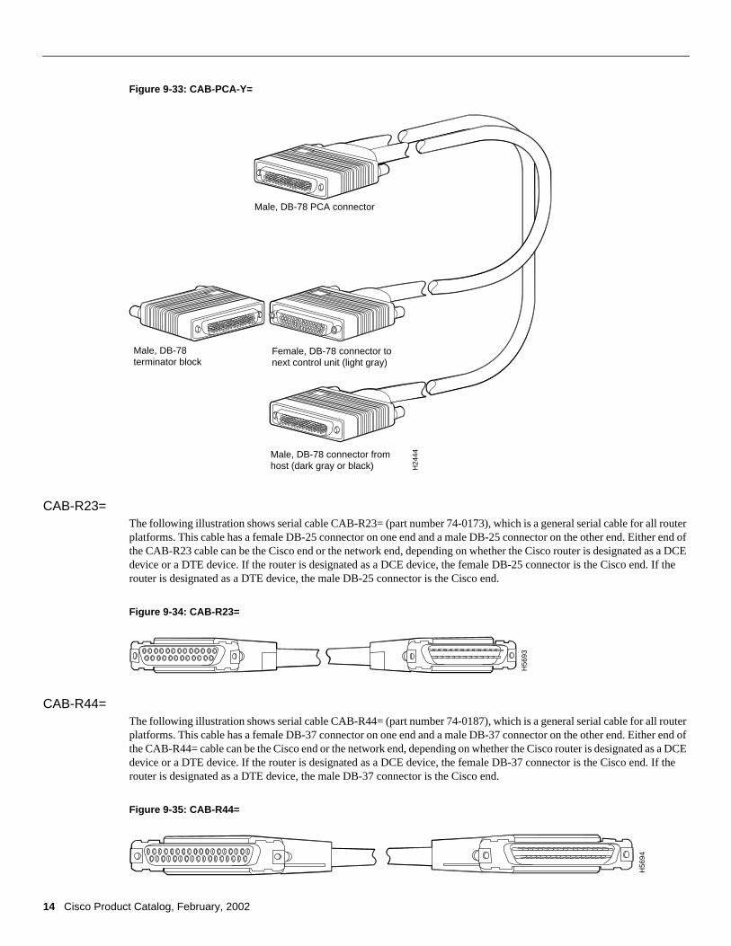
CAB-R23=The following illustration shows serial cable CAB-R23= (part number 74-0173), which is a general serial cable for all routerplatforms. This cable has a female DB-25 connector on one end and a male DB-25 connector on the other end. Either end ofthe CAB-R23 cable can be the Cisco end or the network end, depending on whether the Cisco router is designated as a DCEdevice or a DTE device. If the router is designated as a DCE device, the female DB-25 connector is the Cisco end. If therouter is designated as a DTE device, the male DB-25 connector is the Cisco end.
Figure 9-34: CAB-R23=
CAB-R44=The following illustration shows serial cable CAB-R44= (part number 74-0187), which is a general serial cable for all routerplatforms. This cable has a female DB-37 connector on one end and a male DB-37 connector on the other end. Either end ofthe CAB-R44= cable can be the Cisco end or the network end, depending on whether the Cisco router is designated as a DCEdevice or a DTE device. If the router is designated as a DCE device, the female DB-37 connector is the Cisco end. If therouter is designated as a DTE device, the male DB-37 connector is the Cisco end.
Figure 9-35: CAB-R44=
H24
44
Male, DB-78 PCA connector
Female, DB-78 connector to next control unit (light gray)
Male, DB-78 connector from host (dark gray or black)
Male, DB-78terminator block
H56
93
H56
94
15Visit Cisco Connection Online at www.cisco.com
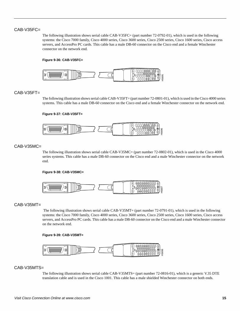
CAB-V35FC=The following illustration shows serial cable CAB-V35FC= (part number 72-0792-01), which is used in the followingsystems: the Cisco 7000 family, Cisco 4000 series, Cisco 3600 series, Cisco 2500 series, Cisco 1600 series, Cisco accessservers, and AccessPro PC cards. This cable has a male DB-60 connector on the Cisco end and a female Winchesterconnector on the network end.
Figure 9-36: CAB-V35FC=
CAB-V35FT=The following illustration shows serial cable CAB-V35FT= (part number 72-0801-01), which is used in the Cisco 4000 seriessystems. This cable has a male DB-60 connector on the Cisco end and a female Winchester connector on the network end.
Figure 9-37: CAB-V35FT=
CAB-V35MC=The following illustration shows serial cable CAB-V35MC= (part number 72-0802-01), which is used in the Cisco 4000series systems. This cable has a male DB-60 connector on the Cisco end and a male Winchester connector on the networkend.
Figure 9-38: CAB-V35MC=
CAB-V35MT= The following illustration shows serial cable CAB-V35MT= (part number 72-0791-01), which is used in the followingsystems: the Cisco 7000 family, Cisco 4000 series, Cisco 3600 series, Cisco 2500 series, Cisco 1600 series, Cisco accessservers, and AccessPro PC cards. This cable has a male DB-60 connector on the Cisco end and a male Winchester connectoron the network end.
Figure 9-39: CAB-V35MT=
CAB-V35MTS=The following illustration shows serial cable CAB-V35MTS= (part number 72-0816-01), which is a generic V.35 DTEtranslation cable and is used in the Cisco 1001. This cable has a male shielded Winchester connector on both ends.
H56
95H
5696
H56
97H
5698
16 Cisco Product Catalog, February, 2002
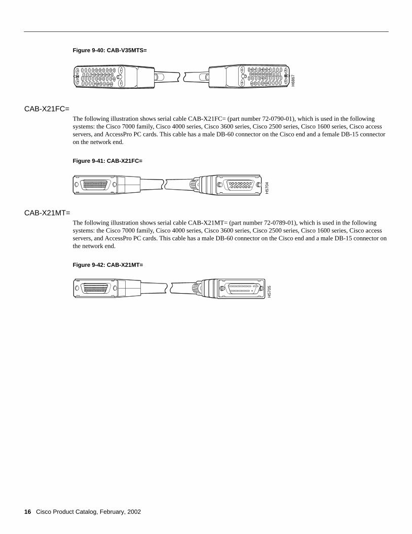
Figure 9-40: CAB-V35MTS=
CAB-X21FC=The following illustration shows serial cable CAB-X21FC= (part number 72-0790-01), which is used in the followingsystems: the Cisco 7000 family, Cisco 4000 series, Cisco 3600 series, Cisco 2500 series, Cisco 1600 series, Cisco accessservers, and AccessPro PC cards. This cable has a male DB-60 connector on the Cisco end and a female DB-15 connectoron the network end.
Figure 9-41: CAB-X21FC=
CAB-X21MT=The following illustration shows serial cable CAB-X21MT= (part number 72-0789-01), which is used in the followingsystems: the Cisco 7000 family, Cisco 4000 series, Cisco 3600 series, Cisco 2500 series, Cisco 1600 series, Cisco accessservers, and AccessPro PC cards. This cable has a male DB-60 connector on the Cisco end and a male DB-15 connector onthe network end.
Figure 9-42: CAB-X21MT=
H68
67
H57
04
1 8
159
H57
05