Embed Size (px)
Citation preview
BSCI
Configuring IS-IS Protocol
Version 1.2 – Module 7
Student Guide
2 Building Scalable Cisco Internetworks (BSCI) v1.2 Copyright 2002, Cisco Systems, Inc.
Copyright 2002, Cisco Systems, Inc. All rights reserved.
Cisco Systems has more than 200 offices in the following countries and regions. Addresses, phone numbers, and fax numbers are listed on the Cisco Web site at www.cisco.com/go/offices.
Argentina • Australia • Austria • Belgium • Brazil • Bulgaria • Canada • Chile • China PRC • Colombia • Costa Rica Croatia • Czech Republic • Denmark • Dubai, UAE • Finland • France • Germany • Greece • Hong Kong SAR • Hungary India • Indonesia • Ireland • Israel • Italy • Japan • Korea • Luxembourg • Malaysia • Mexico • The Netherlands
New Zealand • Norway • Peru • Philippines • Poland • Portugal • Puerto Rico • Romania • Russia • Saudi Arabia Scotland • Singapore • Slovakia • Slovenia • South Africa • Spain • Sweden • Switzerland • Taiwan • Thailand • Turkey Ukraine •
United Kingdom • United States • Venezuela • Vietnam • Zimbabwe
Copyright 2002, Cisco Systems, Inc. All rights reserved. CCIP, the Cisco Powered Network mark, the Cisco Systems Verified logo, Cisco Unity, Follow Me Browsing, FormShare, Internet Quotient, iQ
Breakthrough, iQ Expertise, iQ FastTrack, the iQ logo, iQ Net Readiness Scorecard, Networking Academy, ScriptShare, SMARTnet, TransPath, and Voice LAN are trademarks of Cisco Systems, Inc.; Changing the Way We Work, Live, Play, and Learn, Discover All That’s Possible, The Fastest Way to Increase Your Internet Quotient, and iQuick Study are service marks of Cisco Systems, Inc.; and Aironet, ASIST, BPX, Catalyst, CCDA, CCDP, CCIE, CCNA, CCNP, Cisco, the Cisco Certified Internetwork Expert logo, Cisco IOS, the Cisco IOS logo, Cisco Press, Cisco Systems, Cisco Systems Capital, the Cisco Systems logo, Empowering the Internet Generation, Enterprise/Solver, EtherChannel, EtherSwitch, Fast Step, GigaStack, IOS, IP/TV, LightStream, MGX, MICA, the Networkers logo, Network Registrar, Packet, PIX, Post-Routing, Pre-Routing, RateMUX, Registrar, SlideCast, StrataView Plus, Stratm, SwitchProbe, TeleRouter, and VCO are registered trademarks of Cisco Systems, Inc. and/or its affiliates in the U.S. and certain other countries.
All other trademarks mentioned in this document or Web site are the property of their respective owners. The use of the word partner does not imply a partnership relationship between Cisco and any other company. (0203R)
Printed in the USA
Copyright 2002, Cisco Systems, Inc. Configuring IS-IS Protocol 3
Configuring IS-IS Protocol
Overview This lesson provides an overview of Intermediate System-to-Intermediate System (IS-IS) technology, and its structures and protocols, as well as basic configuration examples. The lesson begins with Open System Interconnection (OSI) routing and then focuses on Integrated IS-IS as a version that supports IP networks. Basic IS-IS and Integrated IS-IS router configuration commands, examples, and some troubleshooting guidelines are presented at the end of the lesson. The major part of this lesson is dedicated to an explanation of IS-IS concepts and capabilities, including hierarchy and addressing of OSI-based networks.
Outline The lesson includes these sections:
! Objectives
! Introduction to OSI Protocols and IS-IS Routing
! Operation of IS-IS
! IP and OSI Routing with Integrated IS-IS
! Basic Integrated IS-IS Router Configuration
! Modeling WAN Networks in Integrated IS-IS
! Summary
! Review Questions
4 Building Scalable Cisco Internetworks (BSCI) v1.2 Copyright 2002, Cisco Systems, Inc.
Objectives This section lists the lesson objectives.
! Explain basic OSI terminology and network layer protocols used in OSI
! Identify similarities and differences between Integrated IS-IS and OSPF
! Identify characteristics of an effective addressing plan for IS-IS deployment
! Explain how networks and interfaces are represented in IS-IS
! List the types of IS-IS routers and their role in IS-IS area design
! Describe the hierarchical structure of IS-IS areas
© 2002, Cisco Systems, Inc. All rights reserved. BSCI v1.2—7-3
Objectives
Upon completing this lesson, you will be able to:• Explain basic OSI terminology and network layer
protocols used in OSI
• Identify similarities and differences between Integrated IS-IS and OSPF
• Identify characteristics of an effective addressing plan for IS-IS deployment
• Explain how networks and interfaces are represented in IS-IS
• List the types of IS-IS routers and their role in IS-IS area design
• Describe the hierarchical structure of IS-IS areas
Copyright 2002, Cisco Systems, Inc. Configuring IS-IS Protocol 5
Objectives (cont.)
! Describe the concept of establishing adjacencies
! Describe the concepts of routing traffic transport and database synchronization
! Explain the basic principles of area routing
! Explain IS-IS nonbroadcast multiaccess (NBMA) network modeling solutions in switched WAN networks
! Identify the steps to configure Cisco routers for proper Integrated IS-IS operation, given an addressing scheme and other laboratory parameters
! Identify verification methods that ensure proper operation of Integrated IS-IS on Cisco routers
© 2002, Cisco Systems, Inc. All rights reserved. BSCI v1.2—7-4
Objectives (cont.)
• Describe the concept of establishing adjacencies
• Describe the concepts of routing traffic transport and database synchronization
• Explain the basic principles of area routing
• Explain IS-IS NBMA (non-broadcast multi-access network) modeling solutions in switched WAN networks
• Given an addressing scheme and other laboratory parameters, identify the steps to configure Cisco routers for proper Integrated IS-IS operation
• Identify verification methods which ensure proper operation of Integrated IS-IS on Cisco routers
6 Building Scalable Cisco Internetworks (BSCI) v1.2 Copyright 2002, Cisco Systems, Inc.
Introduction to OSI Protocols and IS-IS Routing
The OSI protocols are part of an international program to develop data-networking protocols and other standards that facilitate multivendor equipment interoperability. The OSI program grew out of a need for international networking standards and is designed to facilitate communication between hardware and software systems despite differences in underlying architectures.
The OSI specifications were conceived and implemented by two international standards organizations: the International Organization for Standardization (ISO) and the International Telecommunication Union Telecommunication Standardization Sector (ITU-T).
The world of OSI internetworking includes various network services with these characteristics:
! Independence of underlying communications infrastructure
! End-to-end transfer
! Transparency
! Quality of service (QoS) selection
! Addressing
© 2002, Cisco Systems, Inc. All rights reserved. BSCI v1.2—7-6
OSI Protocols
ISO and OSI? • The International Organization for
Standardization (ISO) has been constituted to develop standards for data networking.
• The Open System Interconnection (OSI) protocols represent an international standardization program that facilitatesmultivendor equipment interoperability.
Copyright 2002, Cisco Systems, Inc. Configuring IS-IS Protocol 7
The OSI protocol suite supports numerous standard protocols at the physical, data-link, network, transport session, presentation, and application layers.
OSI network-layer addressing is implemented by using two types of hierarchical addresses: network service access point (NSAP) addresses and network-entity titles. An NSAP is a conceptual point on the boundary between the network and the transport layers. The NSAP is the location at which OSI network services are provided to the transport layer. Each transport-layer entity is assigned a single NSAP, which is individually addressed in an OSI internetwork using NSAP addresses.
The OSI protocol suite specifies two routing protocols at the network layer: End System-to-Intermediate System (ES-IS) and Intermediate System-to-Intermediate System (IS-IS). In addition, the OSI suite implements two types of network services: connectionless service and connection-oriented service.
© 2002, Cisco Systems, Inc. All rights reserved. BSCI v1.2—7-7
OSI Protocols (cont.)
The OSI protocol suite supports:• Numerous standard protocols at each layer of
the OSI reference model
• OSI network-layer hierarchical addressing
• Two routing protocols at the network layer
8 Building Scalable Cisco Internetworks (BSCI) v1.2 Copyright 2002, Cisco Systems, Inc.
In an OSI network four significant architectural entities exist: hosts, areas, a backbone, and a domain. A domain is any portion of an OSI network that is under a common administrative authority. Within any OSI domain, one or more areas can be defined. An area is a logical entity; it is formed by a set of contiguous routers and the data links that connect them. All routers in the same area exchange information about all the hosts that they can reach. The areas are connected to form a backbone. All routers on the backbone know how to reach all areas. The term “end system” (ES) refers to any nonrouting host or node; “intermediate system” (IS) refers to a router. These terms are the basis for the OSI ES-IS and IS-IS protocols.
© 2002, Cisco Systems, Inc. All rights reserved. BSCI v1.2—7-8
OSI Protocols—Terminology
Terminology used in OSI• End system (ES) is any nonrouting
network nodes (host)
• Intermediate system (IS) is a router
• An area is a logical entity
–Formed by a set of contiguous routers, hosts,and the data links that connect them
• Domain is a collection of connected areas
Copyright 2002, Cisco Systems, Inc. Configuring IS-IS Protocol 9
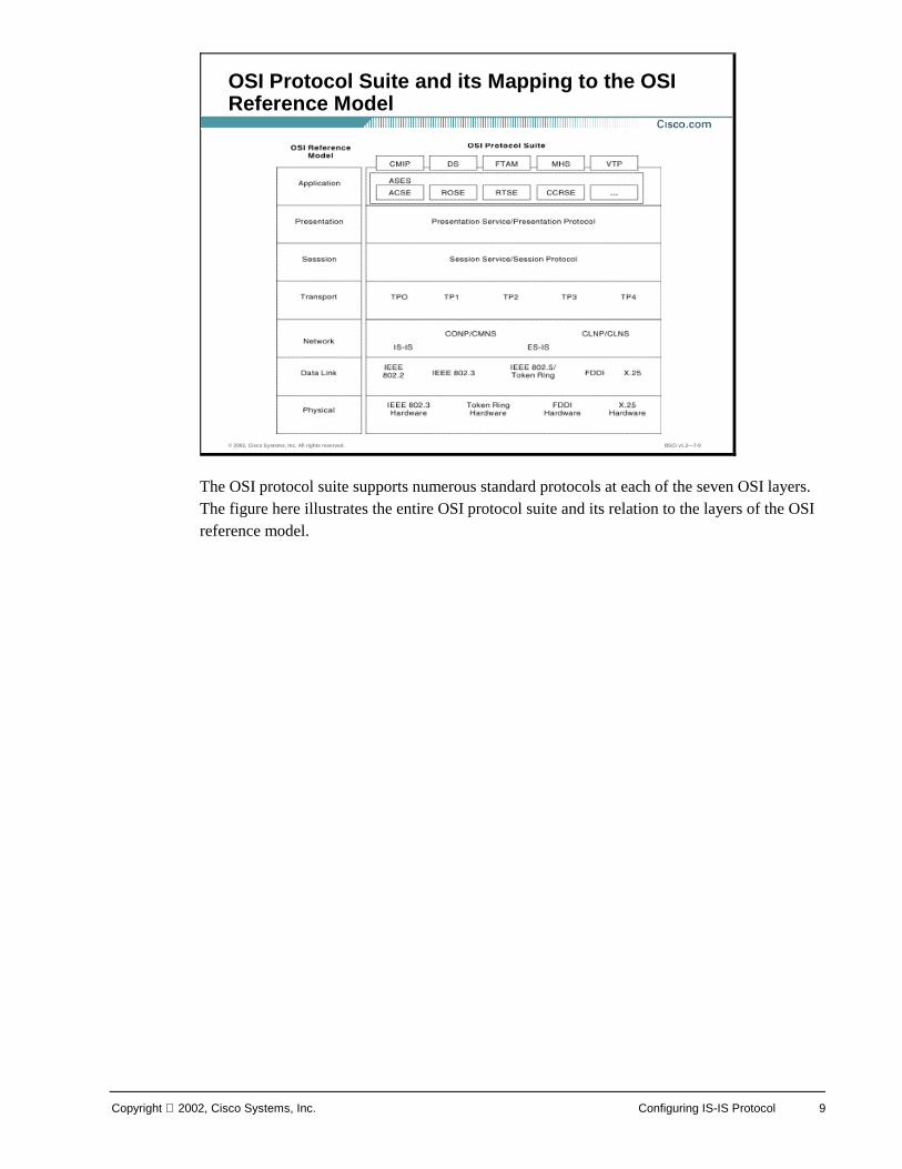
The OSI protocol suite supports numerous standard protocols at each of the seven OSI layers. The figure here illustrates the entire OSI protocol suite and its relation to the layers of the OSI reference model.
© 2002, Cisco Systems, Inc. All rights reserved. BSCI v1.2—7-9
OSI Protocol Suite and its Mapping to the OSI Reference Model
10 Building Scalable Cisco Internetworks (BSCI) v1.2 Copyright 2002, Cisco Systems, Inc.
Connectionless Network Service (CLNS) uses a datagram data transfer service and does not require a circuit to be established before data is transmitted. In contrast, Connection-Mode Network Service (CMNS) requires a circuit to be established before transmitting data. While CLNS and CMNS define the actual services provided to the OSI transport layer entities that operate immediately above the network layer, Connectionless Network Protocol (CLNP) and Connection-Oriented Network Protocol (CONP) name the protocols that these services use to convey data at the network layer. CLNP is the OSI equivalent of IP.
© 2002, Cisco Systems, Inc. All rights reserved. BSCI v1.2—7-10
OSI Network Services—What to Route in OSI Environment?
Two types of OSI network-layer services are available to the OSI transport layer: • Connectionless Network Service (CLNS)
–CLNS performs datagram transport
• Connection-Mode Network Service (CMNS)
–CMNS requires explicit establishmentof paths between communicating transport-layer entities
Copyright 2002, Cisco Systems, Inc. Configuring IS-IS Protocol 11
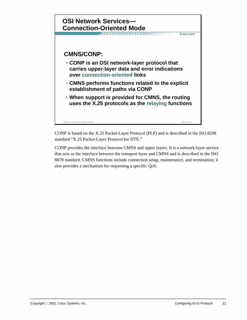
CONP is based on the X.25 Packet-Layer Protocol (PLP) and is described in the ISO 8208 standard “X.25 Packet-Layer Protocol for DTE.”
CONP provides the interface between CMNS and upper layers. It is a network-layer service that acts as the interface between the transport layer and CMNS and is described in the ISO 8878 standard. CMNS functions include connection setup, maintenance, and termination; it also provides a mechanism for requesting a specific QoS.
© 2002, Cisco Systems, Inc. All rights reserved. BSCI v1.2—7-11
OSI Network Services—Connection-Oriented Mode
CMNS/CONP:• CONP is an OSI network-layer protocol that
carries upper-layer data and error indications over connection-oriented links
• CMNS performs functions related to the explicit establishment of paths via CONP
• When support is provided for CMNS, the routing uses the X.25 protocols as the relaying functions
12 Building Scalable Cisco Internetworks (BSCI) v1.2 Copyright 2002, Cisco Systems, Inc.
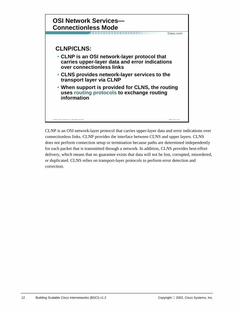
CLNP is an OSI network-layer protocol that carries upper-layer data and error indications over connectionless links. CLNP provides the interface between CLNS and upper layers. CLNS does not perform connection setup or termination because paths are determined independently for each packet that is transmitted through a network. In addition, CLNS provides best-effort delivery, which means that no guarantee exists that data will not be lost, corrupted, misordered, or duplicated. CLNS relies on transport-layer protocols to perform error detection and correction.
© 2002, Cisco Systems, Inc. All rights reserved. BSCI v1.2—7-12
OSI Network Services—Connectionless Mode
CLNP/CLNS:• CLNP is an OSI network-layer protocol that
carries upper-layer data and error indications over connectionless links
• CLNS provides network-layer services to the transport layer via CLNP
• When support is provided for CLNS, the routing uses routing protocols to exchange routing information
Copyright 2002, Cisco Systems, Inc. Configuring IS-IS Protocol 13
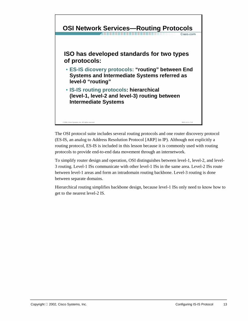
The OSI protocol suite includes several routing protocols and one router discovery protocol (ES-IS, an analog to Address Resolution Protocol [ARP] in IP). Although not explicitly a routing protocol, ES-IS is included in this lesson because it is commonly used with routing protocols to provide end-to-end data movement through an internetwork.
To simplify router design and operation, OSI distinguishes between level-1, level-2, and level-3 routing. Level-1 ISs communicate with other level-1 ISs in the same area. Level-2 ISs route between level-1 areas and form an intradomain routing backbone. Level-3 routing is done between separate domains.
Hierarchical routing simplifies backbone design, because level-1 ISs only need to know how to get to the nearest level-2 IS.
© 2002, Cisco Systems, Inc. All rights reserved. BSCI v1.2—7-13
OSI Network Services—Routing Protocols
ISO has developed standards for two types of protocols:• ES-IS dicovery protocols: “routing” between End
Systems and Intermediate Systems referred as level-0 “routing”
• IS-IS routing protocols: hierarchical (level-1, level-2 and level-3) routing between Intermediate Systems
14 Building Scalable Cisco Internetworks (BSCI) v1.2 Copyright 2002, Cisco Systems, Inc.
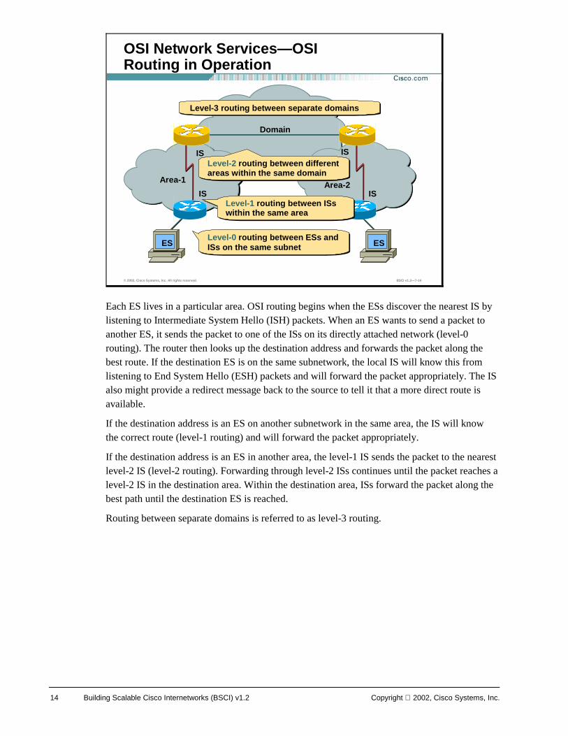
Each ES lives in a particular area. OSI routing begins when the ESs discover the nearest IS by listening to Intermediate System Hello (ISH) packets. When an ES wants to send a packet to another ES, it sends the packet to one of the ISs on its directly attached network (level-0 routing). The router then looks up the destination address and forwards the packet along the best route. If the destination ES is on the same subnetwork, the local IS will know this from listening to End System Hello (ESH) packets and will forward the packet appropriately. The IS also might provide a redirect message back to the source to tell it that a more direct route is available.
If the destination address is an ES on another subnetwork in the same area, the IS will know the correct route (level-1 routing) and will forward the packet appropriately.
If the destination address is an ES in another area, the level-1 IS sends the packet to the nearest level-2 IS (level-2 routing). Forwarding through level-2 ISs continues until the packet reaches a level-2 IS in the destination area. Within the destination area, ISs forward the packet along the best path until the destination ES is reached.
Routing between separate domains is referred to as level-3 routing.
© 2002, Cisco Systems, Inc. All rights reserved. BSCI v1.2—7-14
OSI Network Services—OSI Routing in Operation
Area-1 Area-2
IS IS
IS IS
ESES
Domain
Level-0 routing between ESs and ISs on the same subnetLevel-0 routing between ESs and ISs on the same subnet
Level-1 routing between ISs within the same area Level-1 routing between ISs within the same area
Level-2 routing between different areas within the same domainLevel-2 routing between different areas within the same domain
Level-3 routing between separate domainsLevel-3 routing between separate domains
Copyright 2002, Cisco Systems, Inc. Configuring IS-IS Protocol 15
For routing in the ISO CLNS/CLNP environment, Cisco routers support these protocols:
! IS-IS: Routers usually operate as ISs and can exchange reachability information with other ISs using the IS-IS protocol. As an IS, a Cisco router can operate at level 1 only, at level 2 only, or at both levels. In the last case, the router can advertise itself at level 1 as an exit point from the area. Integrated IS-IS allows the IS-IS protocol to propagate routing information for other protocols as well as, or instead of, CLNS. Specifically, IS-IS can route CLNS, IP, or both (“dual” mode).
! ISO-IGRP: Cisco routers have available a proprietary routing protocol for CLNS. ISO-IGRP is, as its name suggests, based on Cisco’s Interior Gateway Routing Protocol (IGRP). It uses distance vector technology to propagate routing information. As such, it shares some of the limitations of its IP counterpart, including long convergence times (due to periodic updates and long invalid-times and holdtimes).
! Static CLNS routes: As with IP, static CLNS routes can be created.
© 2002, Cisco Systems, Inc. All rights reserved. BSCI v1.2—7-15
OSI Network Services—IS-IS Routing
Intermediate System to Intermediate System(IS-IS) is a dynamic link-state routing protocol in ISO CLNS environment for routing CLNP• Link-state routing protocol in the OSI stack
Alternative to IS-IS protocols is deploying CISCO ISO-IGRP or static routing
16 Building Scalable Cisco Internetworks (BSCI) v1.2 Copyright 2002, Cisco Systems, Inc.
Various aspects of IS-IS are described in these ISO documents:
! ISO 8473: Documents the ISO CLNP.
! ISO/IEC 8348, Appendix A: Documents NSAP addresses.
! ISO 9542: Documents the ES-IS routing exchange protocol.
! ISO/IEC 10589: Documents the IS-IS intradomain routing exchange protocol.
Additionally, the function of Integrated IS-IS - the use of OSI IS-IS for routing in TCP/IP and dual environments - is described in RFC 1195.
© 2002, Cisco Systems, Inc. All rights reserved. BSCI v1.2—7-16
OSI Network Services—Recommended Reading
• ISO 8473—documents ISO Connectionless Network Protocol (CLNP)
• ISO/IEC 8348 Appendix A—documents NSAP addresses
• ISO 9542—documents the ES-IS routing exchange protocol
• ISO/IEC 10589—documents IS-IS intradomainrouting exchange protocol
Copyright 2002, Cisco Systems, Inc. Configuring IS-IS Protocol 17
IS-IS is the dynamic link-state routing protocol for the OSI protocol stack. As such, it distributes routing information for routing CLNP data for the ISO CLNS environment.
Integrated IS-IS is an implementation of the IS-IS protocol for routing multiple network protocols. Integrated IS-IS tags CLNP routes with information regarding IP networks and subnets. It provides an alternative to OSPF in the IP world, mixing ISO CLNS and IP routing in one protocol. It can be used purely for IP routing, purely for ISO routing, or for a combination of the two.
© 2002, Cisco Systems, Inc. All rights reserved. BSCI v1.2—7-17
Integrated IS-IS vs. OSPF
Integrated IS-IS is an extended version of IS-IS for mixed ISO CLNS and IP environments • Integrated IS-IS (RFC 1195) represents
an alternative to OSPF in the IP world
• Integrated IS-IS and OSPF are both link-state protocols with similar:
–Link-state representation, aging, metrics
–Link-state databases, SPF algorithms
–Update, decision, and flooding processes
18 Building Scalable Cisco Internetworks (BSCI) v1.2 Copyright 2002, Cisco Systems, Inc.
Because the configuration of OSPF is based on a central backbone (area 0), with all other areas, ideally, being physically attached to area 0, certain design constraints will inevitably exist. When this type of hierarchical model is used, a good, consistent IP addressing structure is necessary to summarize addresses into the backbone and reduce the amount of information that is carried in the backbone and advertised across the network.
In comparison, IS-IS also has a hierarchy with level-1 and level-2 routers (area borders lie on links). However, significantly fewer Link State Packets (LSPs; also known as Link State PDUs) get used, and thus, many more routers (at least 1000) can reside in a single area. This capability makes IS-IS more scalable than OSPF. IS-IS allows a more flexible approach to extending the backbone. Adding further level-2 routers can extend the backbone. And this process is less complex than with OSPF.
© 2002, Cisco Systems, Inc. All rights reserved. BSCI v1.2—7-18
Integrated IS-IS vs.OSPF—Area Design
Area design• OSPF is based on a central backbone with
all other areas being attached to it
– In OSPF the border is inside routers (ABRs)
–Each link belongs to one area
• In IS-IS the area borders lie on links
–Each IS-IS router belongs to exactly one level-2 area
– IS-IS allows a more flexible approach to extending the backbone
Copyright 2002, Cisco Systems, Inc. Configuring IS-IS Protocol 19
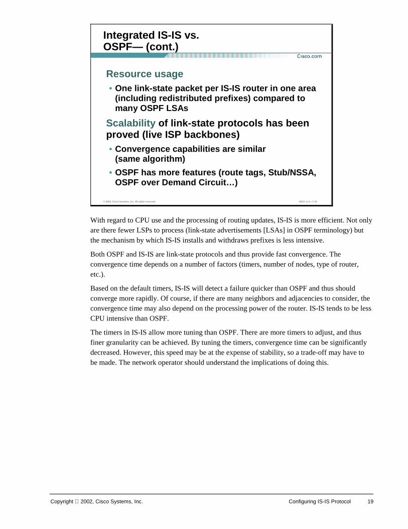
With regard to CPU use and the processing of routing updates, IS-IS is more efficient. Not only are there fewer LSPs to process (link-state advertisements [LSAs] in OSPF terminology) but the mechanism by which IS-IS installs and withdraws prefixes is less intensive.
Both OSPF and IS-IS are link-state protocols and thus provide fast convergence. The convergence time depends on a number of factors (timers, number of nodes, type of router, etc.).
Based on the default timers, IS-IS will detect a failure quicker than OSPF and thus should converge more rapidly. Of course, if there are many neighbors and adjacencies to consider, the convergence time may also depend on the processing power of the router. IS-IS tends to be less CPU intensive than OSPF.
The timers in IS-IS allow more tuning than OSPF. There are more timers to adjust, and thus finer granularity can be achieved. By tuning the timers, convergence time can be significantly decreased. However, this speed may be at the expense of stability, so a trade-off may have to be made. The network operator should understand the implications of doing this.
© 2002, Cisco Systems, Inc. All rights reserved. BSCI v1.2—7-19
Integrated IS-IS vs.OSPF— (cont.)
Resource usage• One link-state packet per IS-IS router in one area
(including redistributed prefixes) compared to many OSPF LSAs
Scalability of link-state protocols has been proved (live ISP backbones)• Convergence capabilities are similar
(same algorithm)
• OSPF has more features (route tags, Stub/NSSA, OSPF over Demand Circuit…)
20 Building Scalable Cisco Internetworks (BSCI) v1.2 Copyright 2002, Cisco Systems, Inc.
Operation of IS-IS
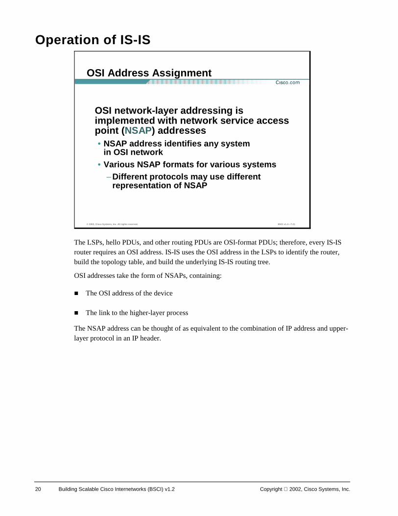
The LSPs, hello PDUs, and other routing PDUs are OSI-format PDUs; therefore, every IS-IS router requires an OSI address. IS-IS uses the OSI address in the LSPs to identify the router, build the topology table, and build the underlying IS-IS routing tree.
OSI addresses take the form of NSAPs, containing:
! The OSI address of the device
! The link to the higher-layer process
The NSAP address can be thought of as equivalent to the combination of IP address and upper-layer protocol in an IP header.
© 2002, Cisco Systems, Inc. All rights reserved. BSCI v1.2—7-21
OSI Address Assignment
OSI network-layer addressing is implemented with network service access point (NSAP) addresses • NSAP address identifies any system
in OSI network • Various NSAP formats for various systems
–Different protocols may use different representation of NSAP
Copyright 2002, Cisco Systems, Inc. Configuring IS-IS Protocol 21
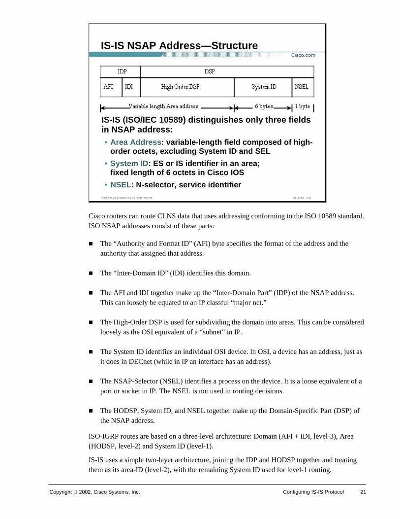
Cisco routers can route CLNS data that uses addressing conforming to the ISO 10589 standard. ISO NSAP addresses consist of these parts:
! The “Authority and Format ID” (AFI) byte specifies the format of the address and the authority that assigned that address.
! The “Inter-Domain ID” (IDI) identifies this domain.
! The AFI and IDI together make up the “Inter-Domain Part” (IDP) of the NSAP address. This can loosely be equated to an IP classful “major net.”
! The High-Order DSP is used for subdividing the domain into areas. This can be considered loosely as the OSI equivalent of a “subnet” in IP.
! The System ID identifies an individual OSI device. In OSI, a device has an address, just as it does in DECnet (while in IP an interface has an address).
! The NSAP-Selector (NSEL) identifies a process on the device. It is a loose equivalent of a port or socket in IP. The NSEL is not used in routing decisions.
! The HODSP, System ID, and NSEL together make up the Domain-Specific Part (DSP) of the NSAP address.
ISO-IGRP routes are based on a three-level architecture: Domain (AFI + IDI, level-3), Area (HODSP, level-2) and System ID (level-1).
IS-IS uses a simple two-layer architecture, joining the IDP and HODSP together and treating them as its area-ID (level-2), with the remaining System ID used for level-1 routing.
© 2002, Cisco Systems, Inc. All rights reserved. BSCI v1.2—7-22
IS-IS NSAP Address—Structure
IS-IS (ISO/IEC 10589) distinguishes only three fields in NSAP address:• Area Address: variable-length field composed of high-
order octets, excluding System ID and SEL
• System ID: ES or IS identifier in an area; fixed length of 6 octets in Cisco IOS
• NSEL: N-selector, service identifier
22 Building Scalable Cisco Internetworks (BSCI) v1.2 Copyright 2002, Cisco Systems, Inc.
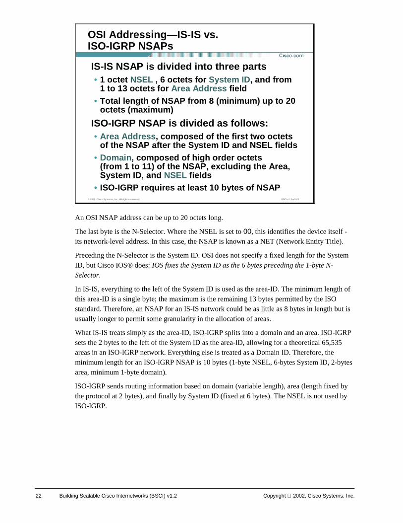
An OSI NSAP address can be up to 20 octets long.
The last byte is the N-Selector. Where the NSEL is set to 00, this identifies the device itself - its network-level address. In this case, the NSAP is known as a NET (Network Entity Title).
Preceding the N-Selector is the System ID. OSI does not specify a fixed length for the System ID, but Cisco IOS® does: IOS fixes the System ID as the 6 bytes preceding the 1-byte N-Selector.
In IS-IS, everything to the left of the System ID is used as the area-ID. The minimum length of this area-ID is a single byte; the maximum is the remaining 13 bytes permitted by the ISO standard. Therefore, an NSAP for an IS-IS network could be as little as 8 bytes in length but is usually longer to permit some granularity in the allocation of areas.
What IS-IS treats simply as the area-ID, ISO-IGRP splits into a domain and an area. ISO-IGRP sets the 2 bytes to the left of the System ID as the area-ID, allowing for a theoretical 65,535 areas in an ISO-IGRP network. Everything else is treated as a Domain ID. Therefore, the minimum length for an ISO-IGRP NSAP is 10 bytes (1-byte NSEL, 6-bytes System ID, 2-bytes area, minimum 1-byte domain).
ISO-IGRP sends routing information based on domain (variable length), area (length fixed by the protocol at 2 bytes), and finally by System ID (fixed at 6 bytes). The NSEL is not used by ISO-IGRP.
© 2002, Cisco Systems, Inc. All rights reserved. BSCI v1.2—7-23
OSI Addressing—IS-IS vs. ISO-IGRP NSAPs
IS-IS NSAP is divided into three parts • 1 octet NSEL , 6 octets for System ID, and from
1 to 13 octets for Area Address field• Total length of NSAP from 8 (minimum) up to 20
octets (maximum)
ISO-IGRP NSAP is divided as follows:• Area Address, composed of the first two octets
of the NSAP after the System ID and NSEL fields • Domain, composed of high order octets
(from 1 to 11) of the NSAP, excluding the Area, System ID, and NSEL fields
• ISO-IGRP requires at least 10 bytes of NSAP
Copyright 2002, Cisco Systems, Inc. Configuring IS-IS Protocol 23
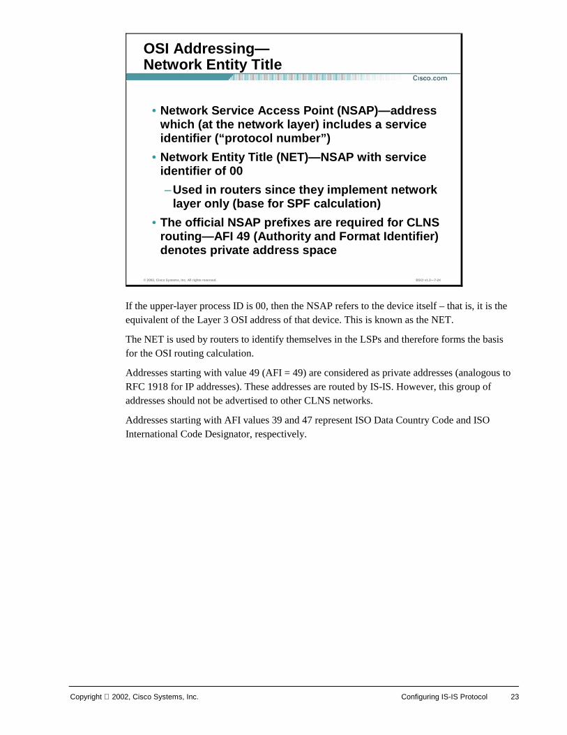
If the upper-layer process ID is 00, then the NSAP refers to the device itself – that is, it is the equivalent of the Layer 3 OSI address of that device. This is known as the NET.
The NET is used by routers to identify themselves in the LSPs and therefore forms the basis for the OSI routing calculation.
Addresses starting with value 49 (AFI = 49) are considered as private addresses (analogous to RFC 1918 for IP addresses). These addresses are routed by IS-IS. However, this group of addresses should not be advertised to other CLNS networks.
Addresses starting with AFI values 39 and 47 represent ISO Data Country Code and ISO International Code Designator, respectively.
© 2002, Cisco Systems, Inc. All rights reserved. BSCI v1.2—7-24
OSI Addressing—Network Entity Title
• Network Service Access Point (NSAP)—address which (at the network layer) includes a service identifier (“protocol number”)
• Network Entity Title (NET)—NSAP with service identifier of 00
–Used in routers since they implement network layer only (base for SPF calculation)
• The official NSAP prefixes are required for CLNS routing—AFI 49 (Authority and Format Identifier) denotes private address space
24 Building Scalable Cisco Internetworks (BSCI) v1.2 Copyright 2002, Cisco Systems, Inc.
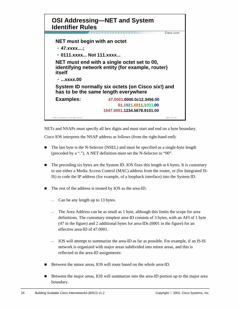
NETs and NSAPs must specify all hex digits and must start and end on a byte boundary.
Cisco IOS interprets the NSAP address as follows (from the right-hand end):
! The last byte is the N-Selector (NSEL) and must be specified as a single-byte length (preceded by a “.”). A NET definition must set the N-Selector to “00”.
! The preceding six bytes are the System ID. IOS fixes this length at 6 bytes. It is customary to use either a Media Access Control (MAC) address from the router, or (for Integrated IS-IS) to code the IP address (for example, of a loopback interface) into the System ID.
! The rest of the address is treated by IOS as the area-ID.
— Can be any length up to 13 bytes.
— The Area Address can be as small as 1 byte, although this limits the scope for area definitions. The customary simplest area-ID consists of 3 bytes, with an AFI of 1 byte (47 in the figure) and 2 additional bytes for area-IDs (0001 in the figure) for an effective area-ID of 47.0001.
— IOS will attempt to summarize the area-ID as far as possible. For example, if an IS-IS network is organized with major areas subdivided into minor areas, and this is reflected in the area-ID assignments:
! Between the minor areas, IOS will route based on the whole area-ID.
! Between the major areas, IOS will summarize into the area-ID portion up to the major area boundary.
© 2002, Cisco Systems, Inc. All rights reserved. BSCI v1.2—7-25
OSI Addressing—NET and System Identifier Rules
NET must begin with an octet• 47.xxxx....;• 0111.xxxx... Not 111.xxxx...
NET must end with a single octet set to 00, identifying network entity (for example, router) itself• ...xxxx.00
System ID normally six octets (on Cisco six!) and has to be the same length everywhereExamples: 47.0001.0000.0c12.3456.00
01.1921.6811.1003.001047.0001.1234.5678.9101.00
Copyright 2002, Cisco Systems, Inc. Configuring IS-IS Protocol 25
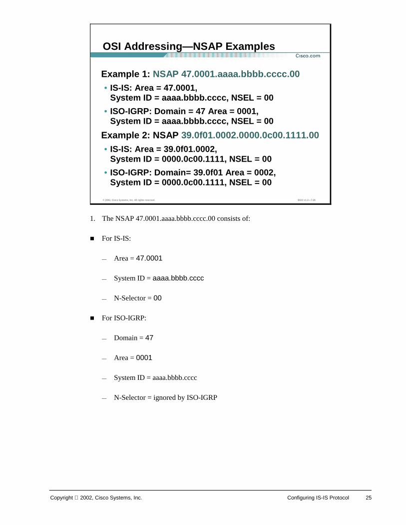
1. The NSAP 47.0001.aaaa.bbbb.cccc.00 consists of:
! For IS-IS:
— Area = 47.0001
— System ID = aaaa.bbbb.cccc
— N-Selector = 00
! For ISO-IGRP:
— Domain = 47
— Area = 0001
— System ID = aaaa.bbbb.cccc
— N-Selector = ignored by ISO-IGRP
© 2002, Cisco Systems, Inc. All rights reserved. BSCI v1.2—7-26
OSI Addressing—NSAP Examples
Example 1: NSAP 47.0001.aaaa.bbbb.cccc.00• IS-IS: Area = 47.0001,
System ID = aaaa.bbbb.cccc, NSEL = 00
• ISO-IGRP: Domain = 47 Area = 0001, System ID = aaaa.bbbb.cccc, NSEL = 00
Example 2: NSAP 39.0f01.0002.0000.0c00.1111.00• IS-IS: Area = 39.0f01.0002,
System ID = 0000.0c00.1111, NSEL = 00
• ISO-IGRP: Domain= 39.0f01 Area = 0002, System ID = 0000.0c00.1111, NSEL = 00
26 Building Scalable Cisco Internetworks (BSCI) v1.2 Copyright 2002, Cisco Systems, Inc.
2. The NSAP 39.0f01.0002.0000.0c00.1111.00 is regarded:
! By IS-IS:
— Area = 39.0f01.0002
— System ID = 0000.0c00.1111
— N-Selector = 00
! By ISO-IGRP:
— Domain = 39.0f01
— Area = 0002
— System ID = 0000.0c00.1111
Copyright 2002, Cisco Systems, Inc. Configuring IS-IS Protocol 27
The area-ID is associated with the IS-IS routing process – a router can be a member of only one level-2 area. Other restrictions are as follows:
! All routers in an area must use the same area address. Indeed, it is the shared area address that actually defines the area.
! ESs will recognize only ISs (and ESs on the same subnetwork) that share the same area address.
! Area routing (level-1) is based on System IDs. Therefore, each device (ES and IS) must have a unique System ID within the area.
! All level-2 ISs come to know about all other ISs in the level-2 backbone. Therefore, they, too, must have unique System IDs.
© 2002, Cisco Systems, Inc. All rights reserved. BSCI v1.2—7-27
Identifying Systems in IS-IS
The area address uniquely identifies the routing area and the System ID identifies each node • All routers within an area must use the same area
address
• An ES may be adjacent to a level-1 router only if they both share a common area address
• Area address is used in level-2 routing
28 Building Scalable Cisco Internetworks (BSCI) v1.2 Copyright 2002, Cisco Systems, Inc.
The System ID must be unique inside an area. It is customary to use either a MAC address from the router, or (particularly for Integrated IS-IS) to code the IP address (for example, of a loopback interface) into the System ID.
It is generally recommended that the System IDs remain unique across the domain; that way there can never be a conflict at level 1 or level 2 if a device is moved into a different area, for example.
All the System IDs in a domain must be of equal length. This is an OSI directive; Cisco enforces this by fixing the length of the System ID at 6 bytes in all cases.
© 2002, Cisco Systems, Inc. All rights reserved. BSCI v1.2—7-28
Identifying Systems in IS-IS—System ID
System ID may be the MAC address (CLNS) or IP address of an interface (IP world)• System ID used in level-1 routing and has to be
unique within an area (and of same length)
• System ID has to be unique within level-2 routers that form routing domain
• General recommendation: domain-wide unique System ID
Copyright 2002, Cisco Systems, Inc. Configuring IS-IS Protocol 29
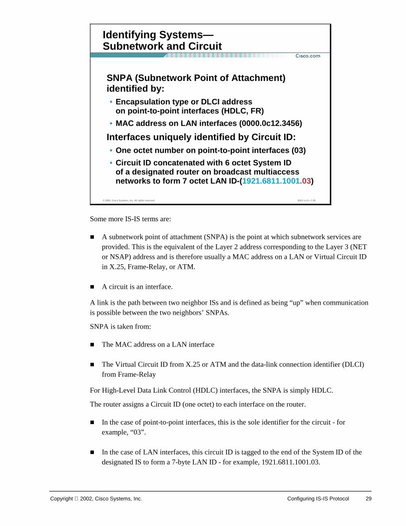
Some more IS-IS terms are:
! A subnetwork point of attachment (SNPA) is the point at which subnetwork services are provided. This is the equivalent of the Layer 2 address corresponding to the Layer 3 (NET or NSAP) address and is therefore usually a MAC address on a LAN or Virtual Circuit ID in X.25, Frame-Relay, or ATM.
! A circuit is an interface.
A link is the path between two neighbor ISs and is defined as being “up” when communication is possible between the two neighbors’ SNPAs.
SNPA is taken from:
! The MAC address on a LAN interface
! The Virtual Circuit ID from X.25 or ATM and the data-link connection identifier (DLCI) from Frame-Relay
For High-Level Data Link Control (HDLC) interfaces, the SNPA is simply HDLC.
The router assigns a Circuit ID (one octet) to each interface on the router.
! In the case of point-to-point interfaces, this is the sole identifier for the circuit - for example, “03”.
! In the case of LAN interfaces, this circuit ID is tagged to the end of the System ID of the designated IS to form a 7-byte LAN ID - for example, 1921.6811.1001.03.
© 2002, Cisco Systems, Inc. All rights reserved. BSCI v1.2—7-29
Identifying Systems—Subnetwork and Circuit
SNPA (Subnetwork Point of Attachment) identified by:• Encapsulation type or DLCI address
on point-to-point interfaces (HDLC, FR)
• MAC address on LAN interfaces (0000.0c12.3456)
Interfaces uniquely identified by Circuit ID:• One octet number on point-to-point interfaces (03)
• Circuit ID concatenated with 6 octet System ID of a designated router on broadcast multiaccessnetworks to form 7 octet LAN ID-(1921.6811.1001.03)
30 Building Scalable Cisco Internetworks (BSCI) v1.2 Copyright 2002, Cisco Systems, Inc.
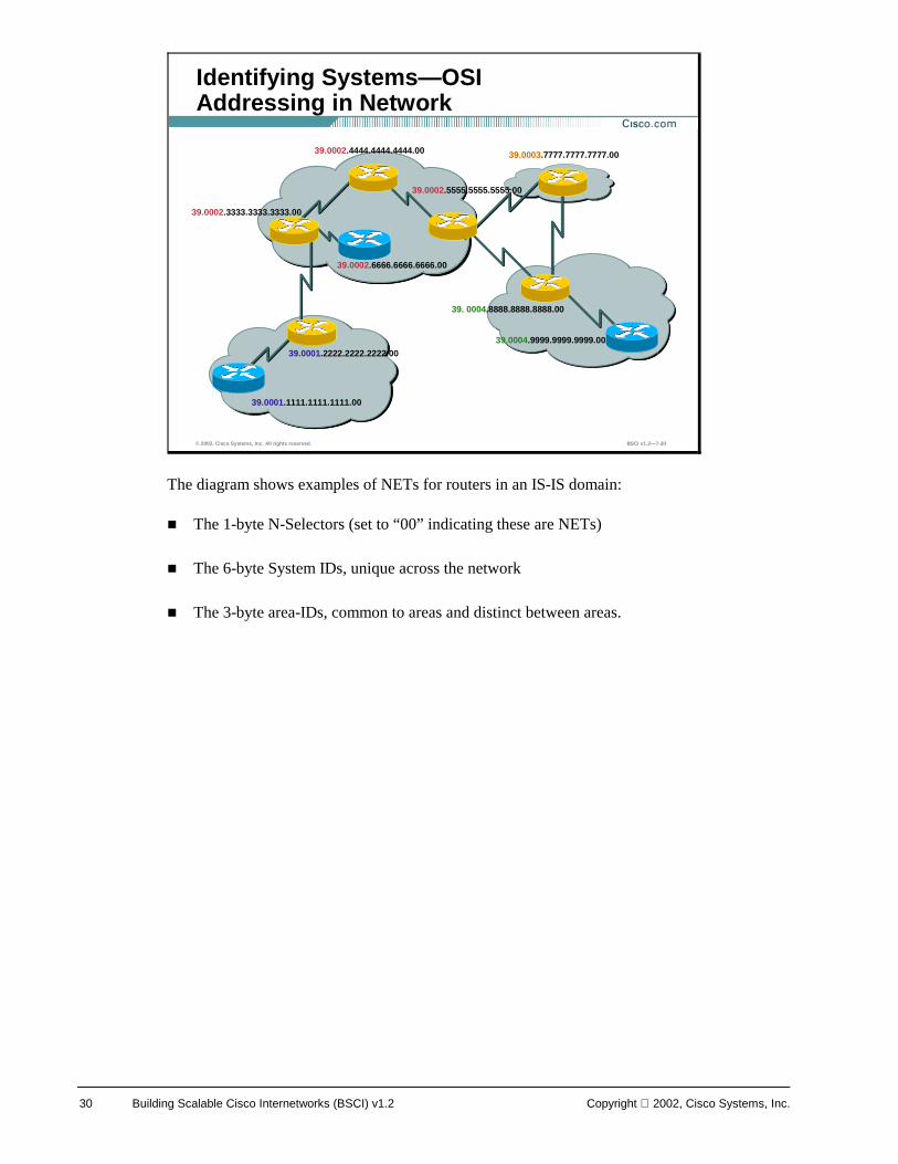
The diagram shows examples of NETs for routers in an IS-IS domain:
! The 1-byte N-Selectors (set to “00” indicating these are NETs)
! The 6-byte System IDs, unique across the network
! The 3-byte area-IDs, common to areas and distinct between areas.
© 2002, Cisco Systems, Inc. All rights reserved. BSCI v1.2—7-30
Identifying Systems—OSIAddressing in Network
39.0002.3333.3333.3333.00
39.0001.2222.2222.2222.00
39.0001.1111.1111.1111.00
39. 0004.8888.8888.8888.00
39.0003.7777.7777.7777.00
39.0004.9999.9999.9999.00
39.0002.4444.4444.4444.00
39.0002.5555.5555.5555.00
39.0002.6666.6666.6666.00
Copyright 2002, Cisco Systems, Inc. Configuring IS-IS Protocol 31
IS-IS protocol data units (PDUs) are encapsulated directly into an OSI data-link frame. There is no CLNP header and no IP header.
The four types of IS-IS PDU are:
! Hello PDU (ESH, ISH, IS-IS Hello [IIH]): Used to establish and maintain adjacencies
! LSP: Used to distribute link-state information
! Partial sequence number PDU (PSNP): Used to acknowledge and request link-state information
! Complete sequence number PDU (CSNP): Used to distribute a router’s complete link-state database
© 2002, Cisco Systems, Inc. All rights reserved. BSCI v1.2—7-31
ISO IS-IS—IS-IS PDU
IS-IS protocol data units (PDUs) are encapsulated directly into a data-link frame
There is no CLNS or IP header in a PDU:• Hello (ESH, ISH, IIH)
• LSP (nonpseudonode and pseudonode)
• PSNP (partial sequence number PDU)
• CSNP (complete sequence number PDU)
32 Building Scalable Cisco Internetworks (BSCI) v1.2 Copyright 2002, Cisco Systems, Inc.
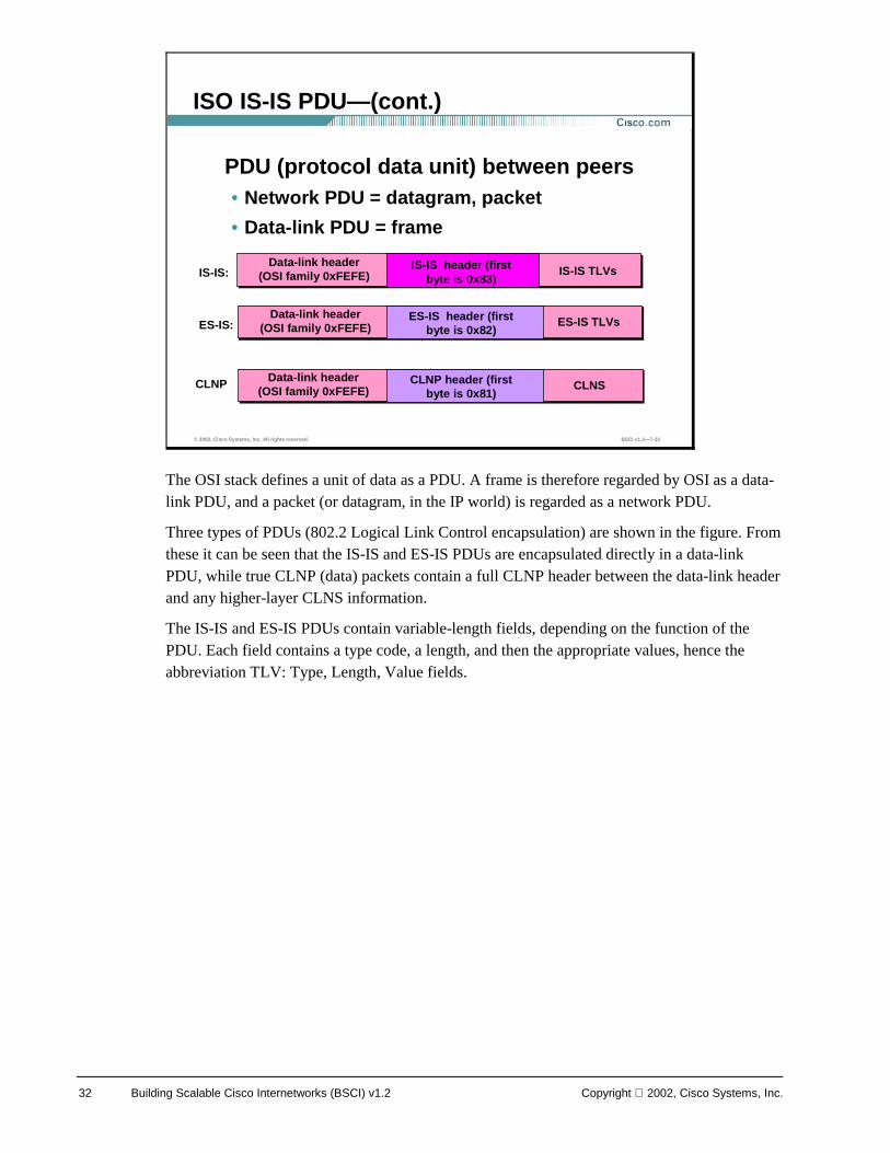
The OSI stack defines a unit of data as a PDU. A frame is therefore regarded by OSI as a data-link PDU, and a packet (or datagram, in the IP world) is regarded as a network PDU.
Three types of PDUs (802.2 Logical Link Control encapsulation) are shown in the figure. From these it can be seen that the IS-IS and ES-IS PDUs are encapsulated directly in a data-link PDU, while true CLNP (data) packets contain a full CLNP header between the data-link header and any higher-layer CLNS information.
The IS-IS and ES-IS PDUs contain variable-length fields, depending on the function of the PDU. Each field contains a type code, a length, and then the appropriate values, hence the abbreviation TLV: Type, Length, Value fields.
© 2002, Cisco Systems, Inc. All rights reserved. BSCI v1.2—7-32
ISO IS-IS PDU—(cont.)
PDU (protocol data unit) between peers• Network PDU = datagram, packet
• Data-link PDU = frame
Data-link header (OSI family 0xFEFE)
IS-IS header (first byte is 0x83)
IS-IS TLVsIS-IS:
Data-link header (OSI family 0xFEFE)
ES-IS header (first byte is 0x82)
ES-IS TLVsES-IS:
Data-link header (OSI family 0xFEFE)
CLNP header (first byte is 0x81)
CLNSCLNP
Copyright 2002, Cisco Systems, Inc. Configuring IS-IS Protocol 33
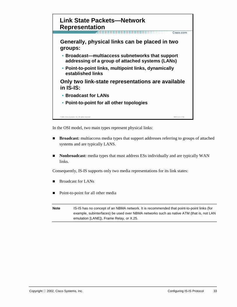
In the OSI model, two main types represent physical links:
! Broadcast: multiaccess media types that support addresses referring to groups of attached systems and are typically LANS.
! Nonbroadcast: media types that must address ESs individually and are typically WAN links.
Consequently, IS-IS supports only two media representations for its link states:
! Broadcast for LANs
! Point-to-point for all other media
Note IS-IS has no concept of an NBMA network. It is recommended that point-to-point links (for example, subinterfaces) be used over NBMA networks such as native ATM (that is, not LAN emulation [LANE]), Frame Relay, or X.25.
© 2002, Cisco Systems, Inc. All rights reserved. BSCI v1.2—7-33
Link State Packets—Network Representation
Generally, physical links can be placed in two groups:• Broadcast—multiaccess subnetworks that support
addressing of a group of attached systems (LANs)
• Point-to-point links, multipoint links, dynamically established links
Only two link-state representations are available in IS-IS:• Broadcast for LANs
• Point-to-point for all other topologies
34 Building Scalable Cisco Internetworks (BSCI) v1.2 Copyright 2002, Cisco Systems, Inc.
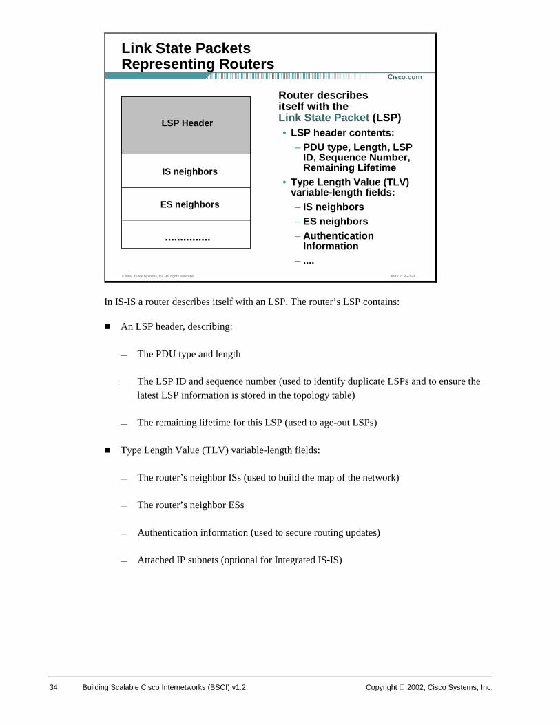
In IS-IS a router describes itself with an LSP. The router’s LSP contains:
! An LSP header, describing:
— The PDU type and length
— The LSP ID and sequence number (used to identify duplicate LSPs and to ensure the latest LSP information is stored in the topology table)
— The remaining lifetime for this LSP (used to age-out LSPs)
! Type Length Value (TLV) variable-length fields:
— The router’s neighbor ISs (used to build the map of the network)
— The router’s neighbor ESs
— Authentication information (used to secure routing updates)
— Attached IP subnets (optional for Integrated IS-IS)
© 2002, Cisco Systems, Inc. All rights reserved. BSCI v1.2—7-34
Link State Packets Representing Routers
Router describes itself with the Link State Packet (LSP)• LSP header contents:
– PDU type, Length, LSP ID, Sequence Number, Remaining Lifetime
• Type Length Value (TLV) variable-length fields:– IS neighbors– ES neighbors– Authentication
Information– ....
LSP Header
IS neighbors
ES neighbors
...............

Copyright 2002, Cisco Systems, Inc. Configuring IS-IS Protocol 35
LSPs are given sequence numbers, to enable receiving routers to ensure they use only the latest LSPs in their route calculations and to avoid duplicate LSPs being entered in the topology tables.
When a router reloads, the sequence number is set initially to 1. The router may then receive its own old LSPs back from its neighbors (which will have the last good sequence number before the router reloaded). It records this number and reissues its own LSPs with the next highest sequence number.
Each LSP has a “remaining lifetime” that is used by the LSP ageing process to ensure that outdated and invalid LSPs are removed from the topology table after a suitable period. (Count to zero operation - 1200 is a default start value.)
© 2002, Cisco Systems, Inc. All rights reserved. BSCI v1.2—7-35
LSP Representing Routers—LSP Header
LSPs are sequenced to prevent duplication of LSPs• Assists with synchronization
• Sequence numbers begin with 1
Sequence numbers are increased to indicate newest LSP• LSPs in LSDB have a remaining lifetime
• Allows synchronization
• Decreasing timer
36 Building Scalable Cisco Internetworks (BSCI) v1.2 Copyright 2002, Cisco Systems, Inc.
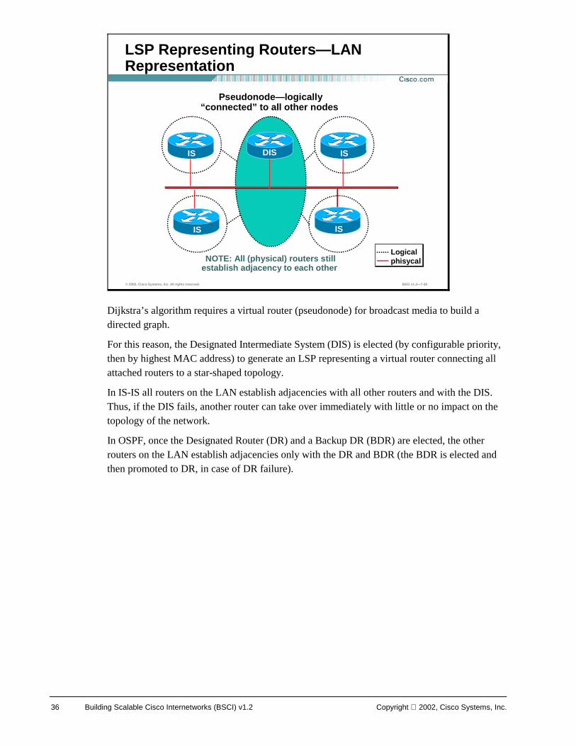
Dijkstra’s algorithm requires a virtual router (pseudonode) for broadcast media to build a directed graph.
For this reason, the Designated Intermediate System (DIS) is elected (by configurable priority, then by highest MAC address) to generate an LSP representing a virtual router connecting all attached routers to a star-shaped topology.
In IS-IS all routers on the LAN establish adjacencies with all other routers and with the DIS. Thus, if the DIS fails, another router can take over immediately with little or no impact on the topology of the network.
In OSPF, once the Designated Router (DR) and a Backup DR (BDR) are elected, the other routers on the LAN establish adjacencies only with the DR and BDR (the BDR is elected and then promoted to DR, in case of DR failure).
© 2002, Cisco Systems, Inc. All rights reserved. BSCI v1.2—7-36
LSP Representing Routers—LAN Representation
IS IS
DIS IS IS
Pseudonode—logically “connected” to all other nodes
NOTE: All (physical) routers still establish adjacency to each other
Logical phisycal
Copyright 2002, Cisco Systems, Inc. Configuring IS-IS Protocol 37
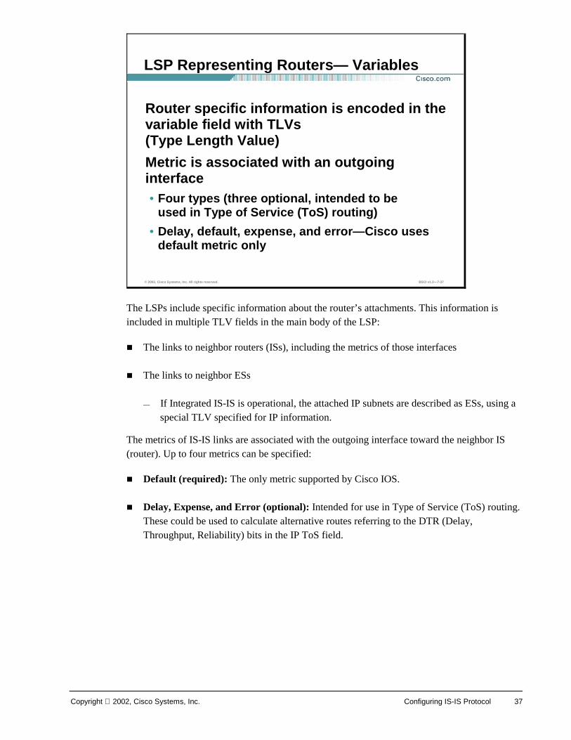
The LSPs include specific information about the router’s attachments. This information is included in multiple TLV fields in the main body of the LSP:
! The links to neighbor routers (ISs), including the metrics of those interfaces
! The links to neighbor ESs
— If Integrated IS-IS is operational, the attached IP subnets are described as ESs, using a special TLV specified for IP information.
The metrics of IS-IS links are associated with the outgoing interface toward the neighbor IS (router). Up to four metrics can be specified:
! Default (required): The only metric supported by Cisco IOS.
! Delay, Expense, and Error (optional): Intended for use in Type of Service (ToS) routing. These could be used to calculate alternative routes referring to the DTR (Delay, Throughput, Reliability) bits in the IP ToS field.
© 2002, Cisco Systems, Inc. All rights reserved. BSCI v1.2—7-37
LSP Representing Routers— Variables
Router specific information is encoded in the variable field with TLVs (Type Length Value)
Metric is associated with an outgoing interface• Four types (three optional, intended to be
used in Type of Service (ToS) routing)
• Delay, default, expense, and error—Cisco uses default metric only
38 Building Scalable Cisco Internetworks (BSCI) v1.2 Copyright 2002, Cisco Systems, Inc.
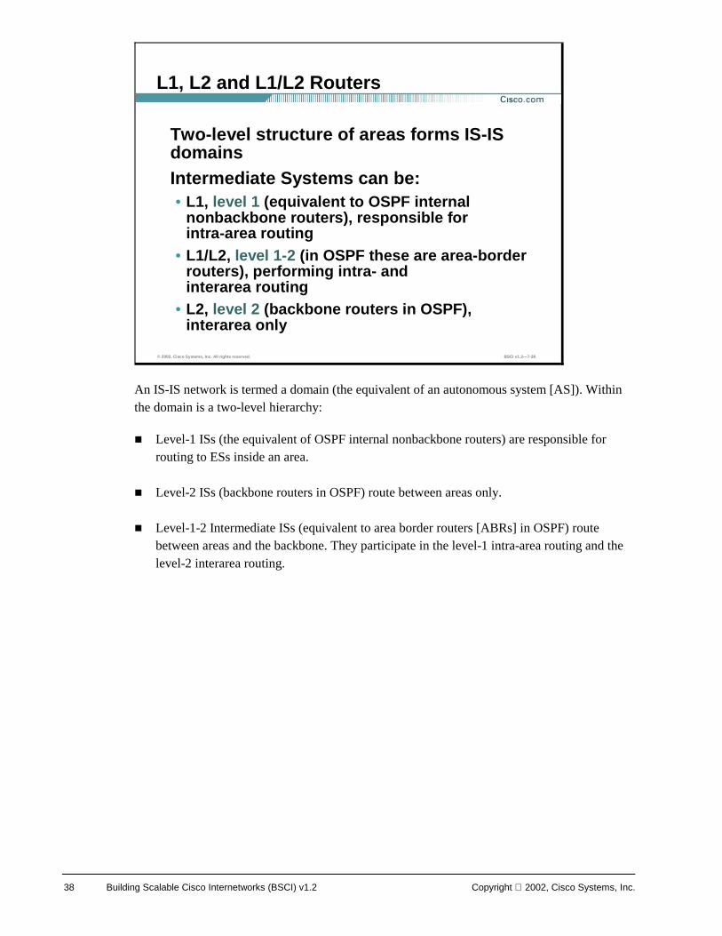
An IS-IS network is termed a domain (the equivalent of an autonomous system [AS]). Within the domain is a two-level hierarchy:
! Level-1 ISs (the equivalent of OSPF internal nonbackbone routers) are responsible for routing to ESs inside an area.
! Level-2 ISs (backbone routers in OSPF) route between areas only.
! Level-1-2 Intermediate ISs (equivalent to area border routers [ABRs] in OSPF) route between areas and the backbone. They participate in the level-1 intra-area routing and the level-2 interarea routing.
© 2002, Cisco Systems, Inc. All rights reserved. BSCI v1.2—7-38
L1, L2 and L1/L2 Routers
Two-level structure of areas forms IS-IS domainsIntermediate Systems can be:• L1, level 1 (equivalent to OSPF internal
nonbackbone routers), responsible for intra-area routing
• L1/L2, level 1-2 (in OSPF these are area-border routers), performing intra- and interarea routing
• L2, level 2 (backbone routers in OSPF), interarea only
Copyright 2002, Cisco Systems, Inc. Configuring IS-IS Protocol 39
Level-1 routers are also referred to as station routers because they enable stations (ESs) to communicate with each other and the rest of the network.
A contiguous group of level-1 routers defines an area. The level-1 routers maintain the level-1 database, which defines the picture of the area itself and its exit points to neighboring areas.
Level-2 routers are also referred to as area routers because they interconnect the level-1 areas. Level-2 routers store a separate database, which contains only the interarea topology information.
© 2002, Cisco Systems, Inc. All rights reserved. BSCI v1.2—7-39
L1 and L2 Routers
Level-1 (L1) routers referred to as station routers • L1 routers constitute an area• L1 routers keep one copy of the link-state
database (its own area “picture”; intra-area information only)
• They enable “stations” (ESs) to communicate
Level-2 (L2) routers referred to as area routers• They store interarea information• They interconnect areas
40 Building Scalable Cisco Internetworks (BSCI) v1.2 Copyright 2002, Cisco Systems, Inc.
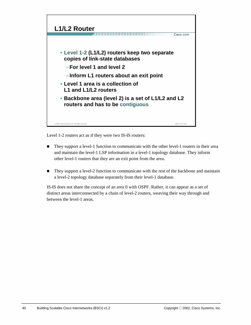
Level 1-2 routers act as if they were two IS-IS routers:
! They support a level-1 function to communicate with the other level-1 routers in their area and maintain the level-1 LSP information in a level-1 topology database. They inform other level-1 routers that they are an exit point from the area.
! They support a level-2 function to communicate with the rest of the backbone and maintain a level-2 topology database separately from their level-1 database.
IS-IS does not share the concept of an area 0 with OSPF. Rather, it can appear as a set of distinct areas interconnected by a chain of level-2 routers, weaving their way through and between the level-1 areas.
© 2002, Cisco Systems, Inc. All rights reserved. BSCI v1.2—7-40
L1/L2 Router
• Level 1-2 (L1/L2) routers keep two separate copies of link-state databases
–For level 1 and level 2
– Inform L1 routers about an exit point
• Level 1 area is a collection of L1 and L1/L2 routers
• Backbone area (level 2) is a set of L1/L2 and L2 routers and has to be contiguous
Copyright 2002, Cisco Systems, Inc. Configuring IS-IS Protocol 41
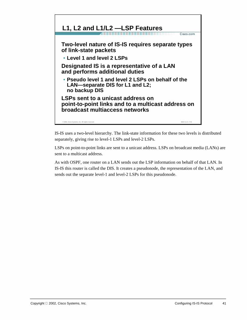
IS-IS uses a two-level hierarchy. The link-state information for these two levels is distributed separately, giving rise to level-1 LSPs and level-2 LSPs.
LSPs on point-to-point links are sent to a unicast address. LSPs on broadcast media (LANs) are sent to a multicast address.
As with OSPF, one router on a LAN sends out the LSP information on behalf of that LAN. In IS-IS this router is called the DIS. It creates a pseudonode, the representation of the LAN, and sends out the separate level-1 and level-2 LSPs for this pseudonode.
© 2002, Cisco Systems, Inc. All rights reserved. BSCI v1.2—7-41
L1, L2 and L1/L2 —LSP Features
Two-level nature of IS-IS requires separate types of link-state packets• Level 1 and level 2 LSPs
Designated IS is a representative of a LAN and performs additional duties• Pseudo level 1 and level 2 LSPs on behalf of the
LAN—separate DIS for L1 and L2; no backup DIS
LSPs sent to a unicast address on point-to-point links and to a multicast address on broadcast multiaccess networks
42 Building Scalable Cisco Internetworks (BSCI) v1.2 Copyright 2002, Cisco Systems, Inc.
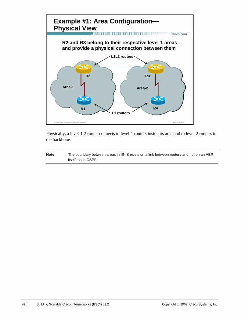
Physically, a level-1-2 router connects to level-1 routers inside its area and to level-2 routers in the backbone.
Note The boundary between areas in IS-IS exists on a link between routers and not on an ABR itself, as in OSPF.
© 2002, Cisco Systems, Inc. All rights reserved. BSCI v1.2—7-42
Example #1: Area Configuration—Physical View
Area-1 Area-2
R3 R2
R1 R4
L1L2 routers
L1 routers
R2 and R3 belong to their respective level-1 areas and provide a physical connection between them
Copyright 2002, Cisco Systems, Inc. Configuring IS-IS Protocol 43
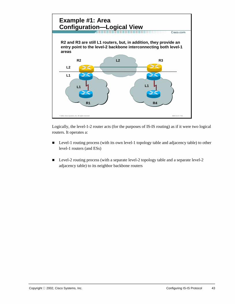
Logically, the level-1-2 router acts (for the purposes of IS-IS routing) as if it were two logical routers. It operates a:
! Level-1 routing process (with its own level-1 topology table and adjacency table) to other level-1 routers (and ESs)
! Level-2 routing process (with a separate level-2 topology table and a separate level-2 adjacency table) to its neighbor backbone routers
© 2002, Cisco Systems, Inc. All rights reserved. BSCI v1.2—7-43
Example #1: Area Configuration—Logical View
L1
R3 R2
R1 R4
R2 and R3 are still L1 routers, but, in addition, they provide an entry point to the level-2 backbone interconnecting both level-1 areas
L2
L2
L1 L1

44 Building Scalable Cisco Internetworks (BSCI) v1.2 Copyright 2002, Cisco Systems, Inc.
For example:
! Area 1 contains two routers:
— One router borders to area 2 and therefore is a level-1-2 IS.
— The other router is contained totally within the area and therefore is level-1-only.
! Area 2 has many routers:
— Some routers are specified as level-1-only and can route internally to that area only (and to the exit points).
— Level-1-2 routers form a chain across the area linking to the neighbor areas.
— Even though the middle of these three level-1-2 routers does not link directly to another area, it must support level-2 routing so the backbone is contiguous.
— If that middle router fails, the other level-1-only routers (though providing a physical path across the area) could not perform the level-2 function, and the backbone would be broken.
© 2002, Cisco Systems, Inc. All rights reserved. BSCI v1.2—7-44
Example #2: L2 and L1/L2 Routers Forming L2 Backbone
L1L2
L1L2
Backbone links
L1L2
L1L2
L1-only
L1-only
Area-2
Area-1
Area-3
Area-4L1-only
L1-only
L1L2
IS-IS domain
This router must behave as level 2 as well in order to guarantee backbone continuity.This router must behave as level 2 as well in order to guarantee backbone continuity.
L2-only

Copyright 2002, Cisco Systems, Inc. Configuring IS-IS Protocol 45
! Area 3 contains one router that borders to area 3, but has no intra-area neighbors, and is therefore level-2-only. In the event that another router was added to area 3, the border router would revert to level-1-2.
The diagram also shows that the border between the areas in an IS-IS network exists on the links between level-2 routers (in contrast to OSPF where the border exists inside the ABR itself).
46 Building Scalable Cisco Internetworks (BSCI) v1.2 Copyright 2002, Cisco Systems, Inc.
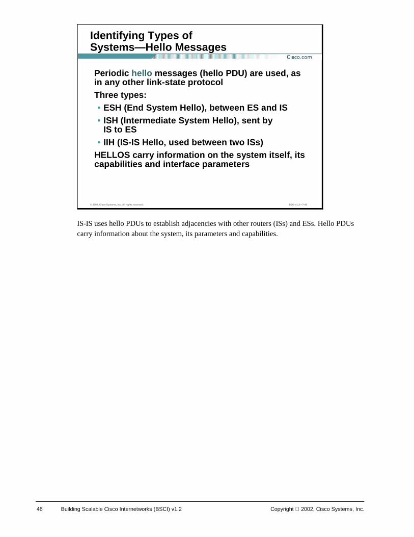
IS-IS uses hello PDUs to establish adjacencies with other routers (ISs) and ESs. Hello PDUs carry information about the system, its parameters and capabilities.
© 2002, Cisco Systems, Inc. All rights reserved. BSCI v1.2—7-45
Identifying Types of Systems—Hello Messages
Periodic hello messages (hello PDU) are used, as in any other link-state protocolThree types:• ESH (End System Hello), between ES and IS• ISH (Intermediate System Hello), sent by
IS to ES• IIH (IS-IS Hello, used between two ISs)
HELLOS carry information on the system itself, its capabilities and interface parameters
Copyright 2002, Cisco Systems, Inc. Configuring IS-IS Protocol 47
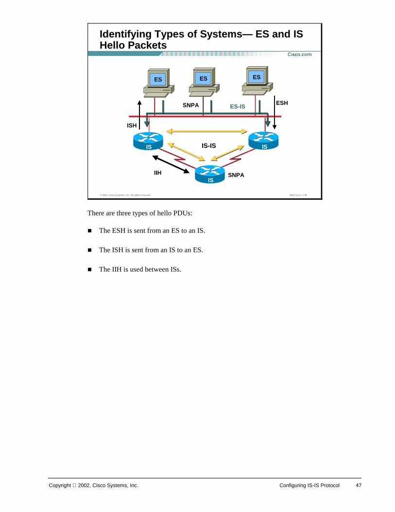
There are three types of hello PDUs:
! The ESH is sent from an ES to an IS.
! The ISH is sent from an IS to an ES.
! The IIH is used between ISs.
© 2002, Cisco Systems, Inc. All rights reserved. BSCI v1.2—7-46
Identifying Types of Systems— ES and IS Hello Packets
ES
IS-IS
ES-IS SNPA
ESES
SNPA
ESH
ISH
IIH
IS
IS
IS
48 Building Scalable Cisco Internetworks (BSCI) v1.2 Copyright 2002, Cisco Systems, Inc.
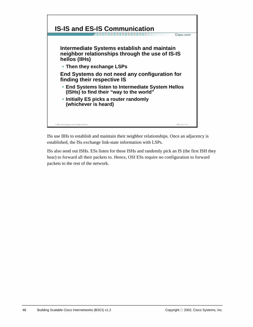
ISs use IIHs to establish and maintain their neighbor relationships. Once an adjacency is established, the ISs exchange link-state information with LSPs.
ISs also send out ISHs. ESs listen for these ISHs and randomly pick an IS (the first ISH they hear) to forward all their packets to. Hence, OSI ESs require no configuration to forward packets to the rest of the network.
© 2002, Cisco Systems, Inc. All rights reserved. BSCI v1.2—7-47
IS-IS and ES-IS Communication
Intermediate Systems establish and maintain neighbor relationships through the use of IS-IS hellos (IIHs) • Then they exchange LSPs
End Systems do not need any configuration for finding their respective IS• End Systems listen to Intermediate System Hellos
(ISHs) to find their “way to the world”• Initially ES picks a router randomly
(whichever is heard)
Copyright 2002, Cisco Systems, Inc. Configuring IS-IS Protocol 49
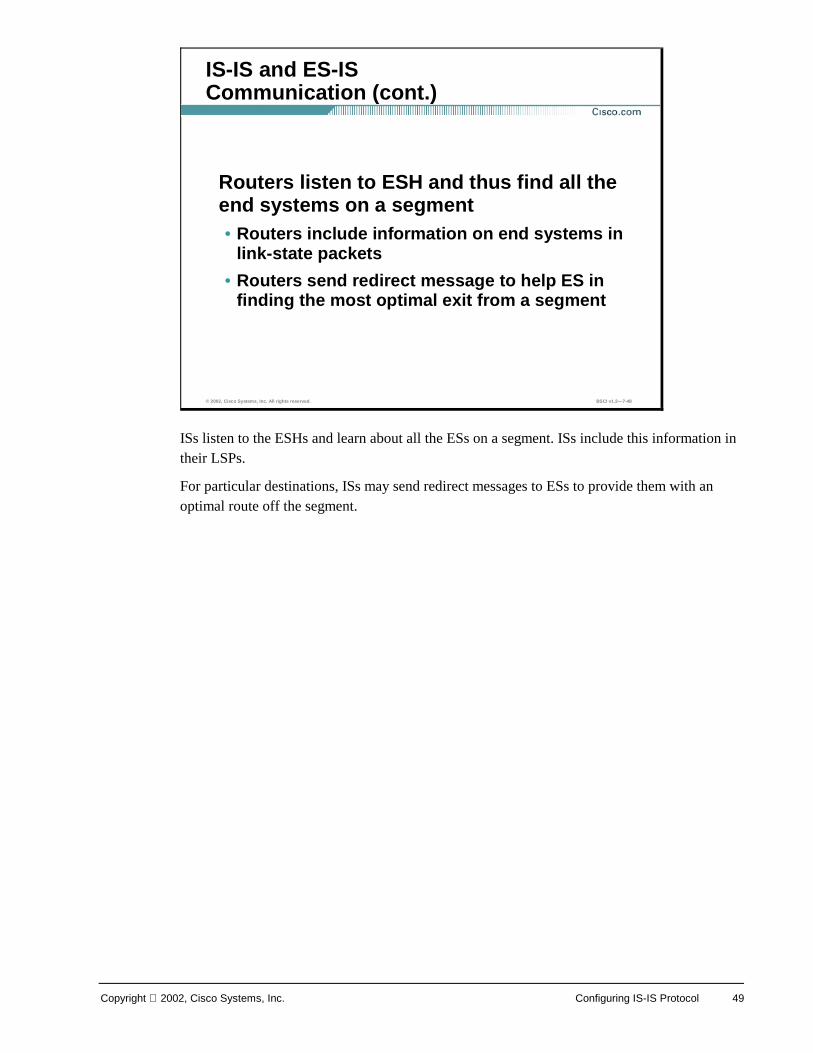
ISs listen to the ESHs and learn about all the ESs on a segment. ISs include this information in their LSPs.
For particular destinations, ISs may send redirect messages to ESs to provide them with an optimal route off the segment.
© 2002, Cisco Systems, Inc. All rights reserved. BSCI v1.2—7-48
IS-IS and ES-IS Communication (cont.)
Routers listen to ESH and thus find all the end systems on a segment• Routers include information on end systems in
link-state packets
• Routers send redirect message to help ES in finding the most optimal exit from a segment
50 Building Scalable Cisco Internetworks (BSCI) v1.2 Copyright 2002, Cisco Systems, Inc.
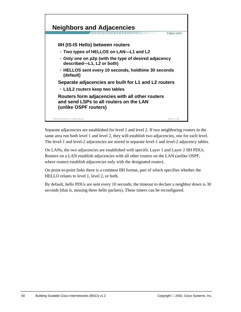
Separate adjacencies are established for level 1 and level 2. If two neighboring routers in the same area run both level 1 and level 2, they will establish two adjacencies, one for each level. The level-1 and level-2 adjacencies are stored in separate level-1 and level-2 adjacency tables.
On LANs, the two adjacencies are established with specific Layer 1 and Layer 2 IIH PDUs. Routers on a LAN establish adjacencies with all other routers on the LAN (unlike OSPF, where routers establish adjacencies only with the designated router).
On point-to-point links there is a common IIH format, part of which specifies whether the HELLO relates to level 1, level 2, or both.
By default, hello PDUs are sent every 10 seconds; the timeout to declare a neighbor down is 30 seconds (that is, missing three hello packets). These timers can be reconfigured.
© 2002, Cisco Systems, Inc. All rights reserved. BSCI v1.2—7-49
Neighbors and Adjacencies
IIH (IS-IS Hello) between routers• Two types of HELLOS on LAN—L1 and L2
• Only one on p2p (with the type of desired adjacency described—L1, L2 or both)
• HELLOS sent every 10 seconds, holdtime 30 seconds(default)
Separate adjacencies are built for L1 and L2 routers• L1/L2 routers keep two tables
Routers form adjacencies with all other routers and send LSPs to all routers on the LAN (unlike OSPF routers)
Copyright 2002, Cisco Systems, Inc. Configuring IS-IS Protocol 51
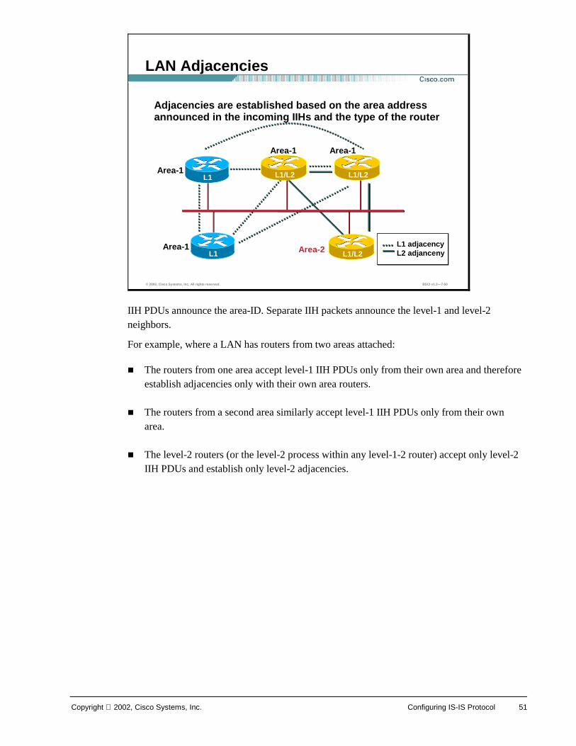
IIH PDUs announce the area-ID. Separate IIH packets announce the level-1 and level-2 neighbors.
For example, where a LAN has routers from two areas attached:
! The routers from one area accept level-1 IIH PDUs only from their own area and therefore establish adjacencies only with their own area routers.
! The routers from a second area similarly accept level-1 IIH PDUs only from their own area.
! The level-2 routers (or the level-2 process within any level-1-2 router) accept only level-2 IIH PDUs and establish only level-2 adjacencies.
© 2002, Cisco Systems, Inc. All rights reserved. BSCI v1.2—7-50
LAN Adjacencies
L1
L1/L2 L1/L2 L1
L1 adjacency L2 adjanceny
Adjacencies are established based on the area address announced in the incoming IIHs and the type of the router
L1/L2 L1/L2
L1/L2
Area-1
Area-1
Area-1 Area-1
Area-2
52 Building Scalable Cisco Internetworks (BSCI) v1.2 Copyright 2002, Cisco Systems, Inc.
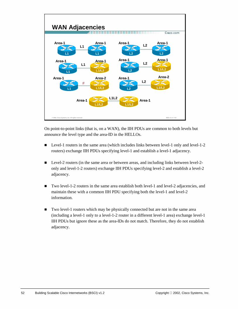
On point-to-point links (that is, on a WAN), the IIH PDUs are common to both levels but announce the level type and the area-ID in the HELLOs.
! Level-1 routers in the same area (which includes links between level-1 only and level-1-2 routers) exchange IIH PDUs specifying level-1 and establish a level-1 adjacency.
! Level-2 routers (in the same area or between areas, and including links between level-2-only and level-1-2 routers) exchange IIH PDUs specifying level-2 and establish a level-2 adjacency.
! Two level-1-2 routers in the same area establish both level-1 and level-2 adjacencies, and maintain these with a common IIH PDU specifying both the level-1 and level-2 information.
! Two level-1 routers which may be physically connected but are not in the same area (including a level-1 only to a level-1-2 router in a different level-1 area) exchange level-1 IIH PDUs but ignore these as the area-IDs do not match. Therefore, they do not establish adjacency.
© 2002, Cisco Systems, Inc. All rights reserved. BSCI v1.2—7-51
WAN Adjacencies
L1 L1
L1/L2
Area-1 Area-1
L1/L2 L1 L1/L2
Area-1 Area-1
L1
L2 L2
Area-1 Area-1
Area-1 Area-2
L1
L1L2
L1
#
L1/L2 L2 L1/L2
Area-1 Area-1L2
L1/L2 L2 L1/L2
Area-1 Area-2L2
L2
L1/L2 L1/L2Area-1 Area-1
Copyright 2002, Cisco Systems, Inc. Configuring IS-IS Protocol 53
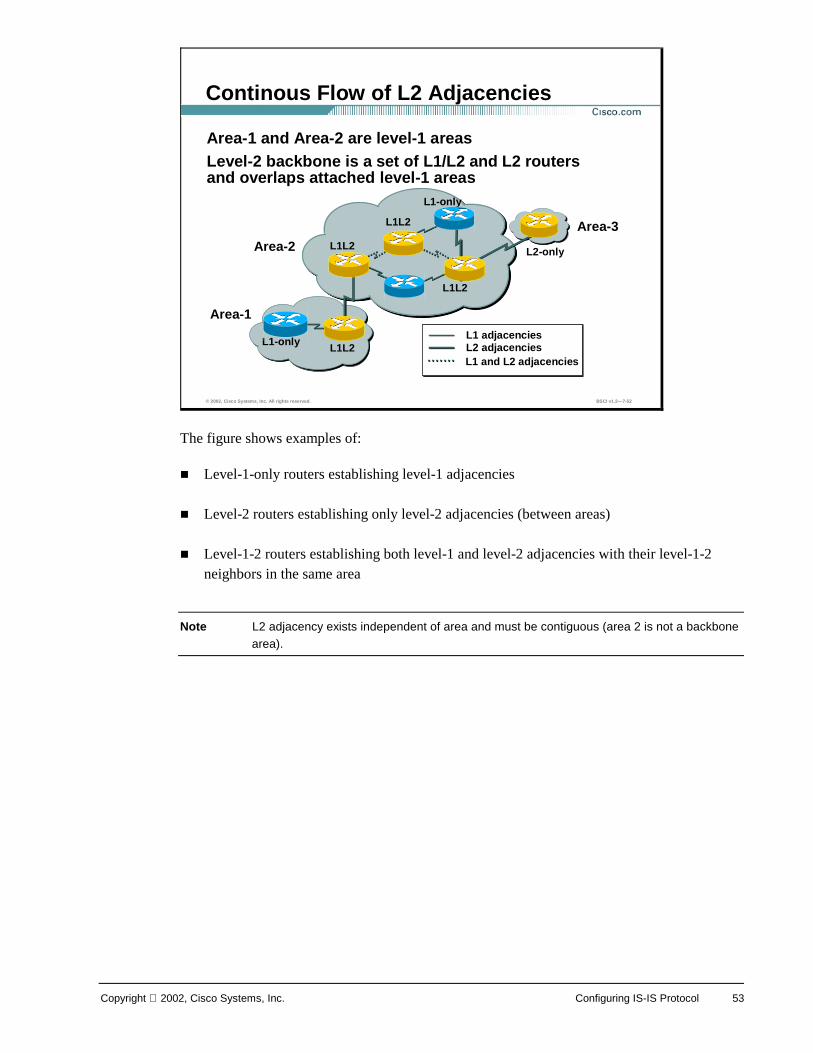
The figure shows examples of:
! Level-1-only routers establishing level-1 adjacencies
! Level-2 routers establishing only level-2 adjacencies (between areas)
! Level-1-2 routers establishing both level-1 and level-2 adjacencies with their level-1-2 neighbors in the same area
Note L2 adjacency exists independent of area and must be contiguous (area 2 is not a backbone area).
© 2002, Cisco Systems, Inc. All rights reserved. BSCI v1.2—7-52
Continous Flow of L2 Adjacencies
L1L2
L1L2
L1L2
L2-only
L1-only
L1-only
L1L2
Area-1
Area-2
Area-3
L1 adjacenciesL2 adjacenciesL1 and L2 adjacencies
Area-1 and Area-2 are level-1 areasLevel-2 backbone is a set of L1/L2 and L2 routersand overlaps attached level-1 areas
54 Building Scalable Cisco Internetworks (BSCI) v1.2 Copyright 2002, Cisco Systems, Inc.
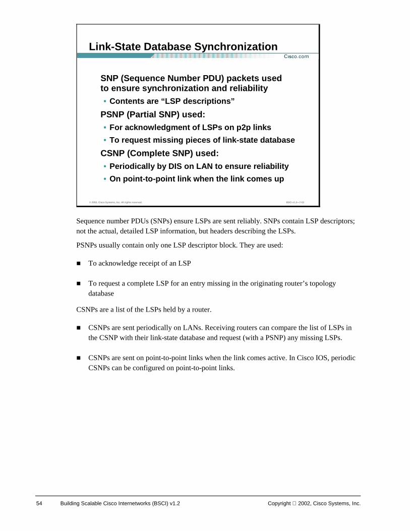
Sequence number PDUs (SNPs) ensure LSPs are sent reliably. SNPs contain LSP descriptors; not the actual, detailed LSP information, but headers describing the LSPs.
PSNPs usually contain only one LSP descriptor block. They are used:
! To acknowledge receipt of an LSP
! To request a complete LSP for an entry missing in the originating router’s topology database
CSNPs are a list of the LSPs held by a router.
! CSNPs are sent periodically on LANs. Receiving routers can compare the list of LSPs in the CSNP with their link-state database and request (with a PSNP) any missing LSPs.
! CSNPs are sent on point-to-point links when the link comes active. In Cisco IOS, periodic CSNPs can be configured on point-to-point links.
© 2002, Cisco Systems, Inc. All rights reserved. BSCI v1.2—7-53
Link-State Database Synchronization
SNP (Sequence Number PDU) packets used to ensure synchronization and reliability• Contents are “LSP descriptions”
PSNP (Partial SNP) used:• For acknowledgment of LSPs on p2p links
• To request missing pieces of link-state database
CSNP (Complete SNP) used:• Periodically by DIS on LAN to ensure reliability
• On point-to-point link when the link comes up
Copyright 2002, Cisco Systems, Inc. Configuring IS-IS Protocol 55
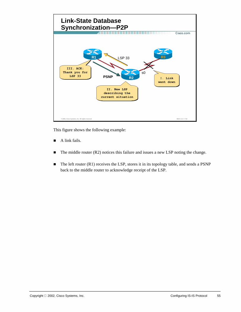
This figure shows the following example:
! A link fails.
! The middle router (R2) notices this failure and issues a new LSP noting the change.
! The left router (R1) receives the LSP, stores it in its topology table, and sends a PSNP back to the middle router to acknowledge receipt of the LSP.
© 2002, Cisco Systems, Inc. All rights reserved. BSCI v1.2—7-54
Link-State Database Synchronization—P2P
R1 R3 LSP 33
PSNP
III. ACK: Thank you for
LSP 33
III. ACK: Thank you for
LSP 33I. Link went down
I. Link went down
II. New LSP describing the
current situation
II. New LSP describing the
current situation
s0
R2
56 Building Scalable Cisco Internetworks (BSCI) v1.2 Copyright 2002, Cisco Systems, Inc.
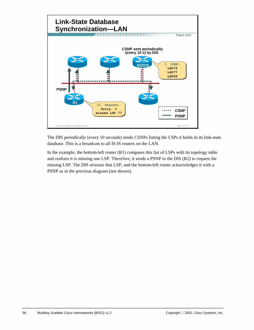
The DIS periodically (every 10 seconds) sends CSNPs listing the LSPs it holds in its link-state database. This is a broadcast to all IS-IS routers on the LAN.
In the example, the bottom-left router (R1) compares this list of LSPs with its topology table and realizes it is missing one LSP. Therefore, it sends a PSNP to the DIS (R2) to request the missing LSP. The DIS reissues that LSP, and the bottom-left router acknowledges it with a PSNP as in the previous diagram (not shown).
© 2002, Cisco Systems, Inc. All rights reserved. BSCI v1.2—7-55
Link-State Database Synchronization—LAN
R1
CSNP sent periodically (every 10 s) by DIS
R2/DIS
PSNP
II. Request:Sorry. I
missed LSP 77
II. Request:Sorry. I
missed LSP 77 CSNP PSNP
I. CSNP:LSP76LSP77LSP88
I. CSNP:LSP76LSP77LSP88

Copyright 2002, Cisco Systems, Inc. Configuring IS-IS Protocol 57
IP and OSI Routing with Integrated IS-IS
Integrated IS-IS supports three types of networks:
! OSI
! IP
! Dual (that is, both the above)
The LSPs can contain many variable-length TLV fields, describing:
! OSI state information
! IP state information
© 2002, Cisco Systems, Inc. All rights reserved. BSCI v1.2—7-57
Integrated IS-IS Routing Protocol
Integrated IS-IS allows for three types of routing domains (OSI, IP, Dual)
Therefore, an IS-IS LSP may contain multiple variable-length fields (TLV)• Some contain OSI-specific information
• Some contain IP-specific information
58 Building Scalable Cisco Internetworks (BSCI) v1.2 Copyright 2002, Cisco Systems, Inc.
Integrated IS-IS LSPs describe IP information in a similar manner to the way IS-IS describes ESs. There are specific TLV types for IP information.
Like all modern routing protocols, Integrated IS-IS supports:
! Variable-Length Subnet Masks (VLSMs) - the mask is sent with the prefix in the updates
! Redistribution of IP routes into and out of IS-IS
! Summarization of IP routes
© 2002, Cisco Systems, Inc. All rights reserved. BSCI v1.2—7-58
Integrated IS-IS—Representing IP Networks
LSP describes IP information in the same way as ESs
Integrated IS-IS has all the features of modern routing protocols• Variable-length mask
• Redistribution
• Summarization
Copyright 2002, Cisco Systems, Inc. Configuring IS-IS Protocol 59
IS-IS can be enabled on Cisco routers for:
! Pure CLNS support
! IP support (Integrated IS-IS), additional to CLNS, or for IP only
However, even if Integrated IS-IS is being used only for IP routing, a NET address is required for Layer 2 forwarding and Dijkstra’s algorithm computation:
! OSI protocols are used to form the neighbor relationship between routers.
! SPF calculations rely on a configured NET address to identify the routers.
© 2002, Cisco Systems, Inc. All rights reserved. BSCI v1.2—7-59
Integrated IS-IS—NET Address Planning
Common CLNS parameters (NET) and area planning are still required even in an IP environment• Even when Integrated IS-IS is used only
for IP routing, routers still establish CLNS adjacencies and use CLNS packets
60 Building Scalable Cisco Internetworks (BSCI) v1.2 Copyright 2002, Cisco Systems, Inc.
To build the OSI forwarding database (the CLNS routing table):
! The link-state database is used to calculate the Shortest-Path-First (SPF) tree to OSI destinations (NETs). The link metrics are totaled along each path to decide which is the shortest to any given destination.
! There are separate link-state databases for level-1 and level-2 routes. Therefore, SPF is run twice (once for each level), and separate SPF trees are created for each level.
! ES reachability is calculated with a partial route calculation (PRC) based on the above level-1 and level-2 SPF trees. (There are no OSI ESs if it is a pure IP Integrated IS-IS environment).
! The best paths are inserted in the CLNS routing table (OSI forwarding database).
© 2002, Cisco Systems, Inc. All rights reserved. BSCI v1.2—7-60
OSI Area Routing—Building OSI Forwarding Table
• When databases are synchronized, Dijkstra(SPF) algorithm is run on the LSDB to calculate the SPF tree
–Criteria: the shortest path to the destination is the lowest total sum of metrics
–Separate route calculations made for L1 and L2 areas in L1/L2 routers
• Partial route calculation (PRC) run to calculate ES reachability
• Best paths are placed in the OSI L1 and L2 forwarding tables
Copyright 2002, Cisco Systems, Inc. Configuring IS-IS Protocol 61
Routing inside a level-1 area is based on the System ID of the destination OSI (NSAP) address.
OSI Packets to other areas are routed to the nearest level-1-2 router.
Level-2 routing is based on the area-ID. If a level-1-2 router receives a packet (from a level-2 neighbor) destined for its own area, it will route it as for level 1, based on the System ID.
© 2002, Cisco Systems, Inc. All rights reserved. BSCI v1.2—7-61
OSI Area Routing
Level-1 intermediate systems• Routing within the area is based on the
System ID portion of the ISO address
• If the destination belongs to another area, they route to the nearest active level-1-2 router
Level-2 intermediate systems• Routing between areas is based on the area
address and considers only the area cost
• If the destination belongs to the same area, they use the least-cost path to the System ID
62 Building Scalable Cisco Internetworks (BSCI) v1.2 Copyright 2002, Cisco Systems, Inc.
When routing a packet from one area that is destined for another area:
! The level-1 routers route the packet to the nearest level-1-2 router. They find the closest exit point from the area, based on receipt of default routes from the level-1-2 routers in their area.
! The level-1-2 router routes the packets into the level-2 backbone based on the destination area-ID. The packet travels across the level-2 backbone to the destination area.
! Once it arrives in the destination area, level-1 routing is again used to route the packet to its final destination inside that area.
The interface between the level-1 world and the level-2 world takes place on a level-1-2 router. The level-1-2 router behaves as if it were both a level-1 router (routing to level-1 destinations) and a level-2 router (routing between areas).
© 2002, Cisco Systems, Inc. All rights reserved. BSCI v1.2—7-62
OSI Area Routing—Routing Between Areas
From level 1 via level 2 to level 1• L1 always sends a packet to a nearest
active L1/L2 router (default routing) • Then the packet travels via L2 routing
towards the destination area where the best L1 path is used
Note: L1/L2 router performs L1 and L2 routing
Copyright 2002, Cisco Systems, Inc. Configuring IS-IS Protocol 63
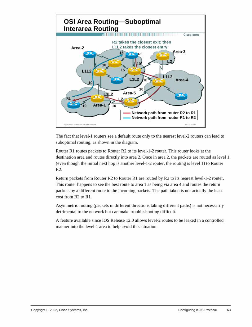
The fact that level-1 routers see a default route only to the nearest level-2 routers can lead to suboptimal routing, as shown in the diagram.
Router R1 routes packets to Router R2 to its level-1-2 router. This router looks at the destination area and routes directly into area 2. Once in area 2, the packets are routed as level 1 (even though the initial next hop is another level-1-2 router, the routing is level 1) to Router R2.
Return packets from Router R2 to Router R1 are routed by R2 to its nearest level-1-2 router. This router happens to see the best route to area 1 as being via area 4 and routes the return packets by a different route to the incoming packets. The path taken is not actually the least cost from R2 to R1.
Asymmetric routing (packets in different directions taking different paths) is not necessarily detrimental to the network but can make troubleshooting difficult.
A feature available since IOS Release 12.0 allows level-2 routes to be leaked in a controlled manner into the level-1 area to help avoid this situation.
© 2002, Cisco Systems, Inc. All rights reserved. BSCI v1.2—7-63
OSI Area Routing—Suboptimal Interarea Routing
L1L2
L1L2
L1L2L1L2
L2
Area-2
Area-1
Area-3
Area-4
Area-5
R2
R1
Network path from router R2 to R1Network path from router R1 to R2
L2
10
15
10
10
10
10 15
R2 takes the closest exit; then L1L2 takes the closest entry
10
10
64 Building Scalable Cisco Internetworks (BSCI) v1.2 Copyright 2002, Cisco Systems, Inc.
An IS-IS domain is the equivalent of an IP AS.
IS-IS can support the interconnection of multiple domains:
! In a pure-OSI environment, ISO-IGRP (Cisco proprietary) interprets the initial domain identifier (IDI) portion of CLNS routes and allows routing between domains. There is also a standard OSI Interdomain Routing Protocol (IDRP), which provides the same function (but is not supported by Cisco).
In an IP environment, an IP interdomain protocol is required. The most common of these is the Border Gateway Protocol (BGP).
© 2002, Cisco Systems, Inc. All rights reserved. BSCI v1.2—7-64
OSI Area Routing— Interconnecting IS-IS Domains
IS-IS routing domain is a collection of IS-IS areas
When interconnecting IS-IS domains the following applies:• In pure IP-environment use BGP
• In pure CLNS use ISO-IGRP or static CLNS routes
Copyright 2002, Cisco Systems, Inc. Configuring IS-IS Protocol 65
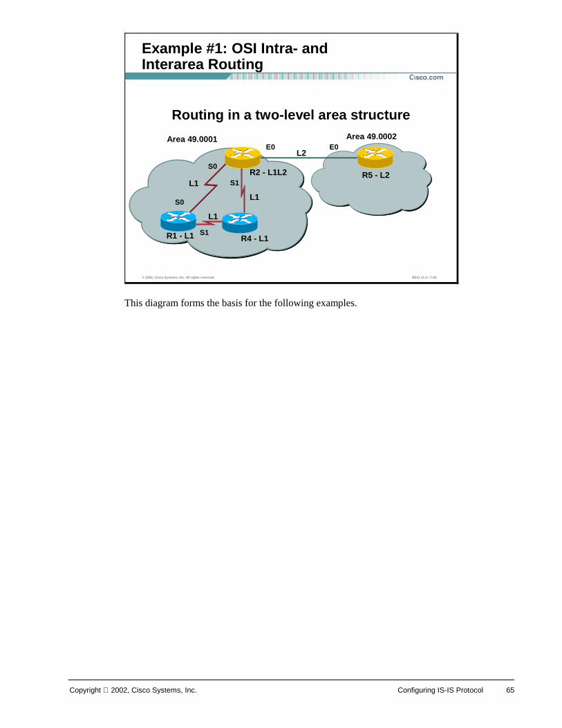
This diagram forms the basis for the following examples.
© 2002, Cisco Systems, Inc. All rights reserved. BSCI v1.2—7-65
Example #1: OSI Intra- and Interarea Routing
Area 49.0001 Area 49.0002
R5 - L2 R2 - L1L2
R1 - L1
L2
L1
Routing in a two-level area structure
R4 - L1
L1
L1
S0
S1
S0
S1
E0 E0
66 Building Scalable Cisco Internetworks (BSCI) v1.2 Copyright 2002, Cisco Systems, Inc.
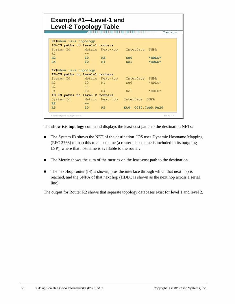
The show isis topology command displays the least-cost paths to the destination NETs:
! The System ID shows the NET of the destination. IOS uses Dynamic Hostname Mapping (RFC 2763) to map this to a hostname (a router’s hostname is included in its outgoing LSP), where that hostname is available to the router.
! The Metric shows the sum of the metrics on the least-cost path to the destination.
! The next-hop router (IS) is shown, plus the interface through which that next hop is reached, and the SNPA of that next hop (HDLC is shown as the next hop across a serial line).
The output for Router R2 shows that separate topology databases exist for level 1 and level 2.
© 2002, Cisco Systems, Inc. All rights reserved. BSCI v1.2—7-66
Example #1—Level-1 and Level-2 Topology Table
R1#show isis topologyIS-IS paths to level-1 routersSystem Id Metric Next-Hop Interface SNPAR1 --R2 10 R2 Se0 *HDLC*R4 10 R4 Se1 *HDLC*
R2#show isis topologyIS-IS paths to level-1 routersSystem Id Metric Next-Hop Interface SNPAR1 10 R1 Se0 *HDLC*R2 --R4 10 R4 Se1 *HDLC*IS-IS paths to level-2 routersSystem Id Metric Next-Hop Interface SNPAR2 --R5 10 R5 Et0 0010.7bb5.9e20
Copyright 2002, Cisco Systems, Inc. Configuring IS-IS Protocol 67
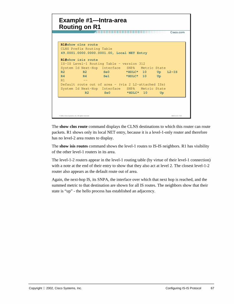
The show clns route command displays the CLNS destinations to which this router can route packets. R1 shows only its local NET entry, because it is a level-1-only router and therefore has no level-2 area routes to display.
The show isis routes command shows the level-1 routes to IS-IS neighbors. R1 has visibility of the other level-1 routers in its area.
The level-1-2 routers appear in the level-1 routing table (by virtue of their level-1 connection) with a note at the end of their entry to show that they also act at level 2. The closest level-1-2 router also appears as the default route out of area.
Again, the next-hop IS, its SNPA, the interface over which that next hop is reached, and the summed metric to that destination are shown for all IS routes. The neighbors show that their state is “up” - the hello process has established an adjacency.
© 2002, Cisco Systems, Inc. All rights reserved. BSCI v1.2—7-67
Example #1—Intra-area Routing on R1
R1#show clns routeCLNS Prefix Routing Table49.0001.0000.0000.0001.00, Local NET Entry
R1#show isis routeIS-IS Level-1 Routing Table - version 312System Id Next-Hop Interface SNPA Metric StateR2 R2 Se0 *HDLC* 10 Up L2-ISR4 R4 Se1 *HDLC* 10 UpR1 --Default route out of area - (via 2 L2-attached ISs)System Id Next-Hop Interface SNPA Metric State
R2 Se0 *HDLC* 10 Up
68 Building Scalable Cisco Internetworks (BSCI) v1.2 Copyright 2002, Cisco Systems, Inc.
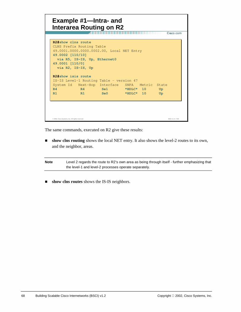
The same commands, executed on R2 give these results:
! show clns routing shows the local NET entry. It also shows the level-2 routes to its own, and the neighbor, areas.
Note Level 2 regards the route to R2’s own area as being through itself - further emphasizing that the level-1 and level-2 processes operate separately.
! show clns routes shows the IS-IS neighbors.
© 2002, Cisco Systems, Inc. All rights reserved. BSCI v1.2—7-68
Example #1—Intra- and Interarea Routing on R2
R2#show clns routeCLNS Prefix Routing Table49.0001.0000.0000.0002.00, Local NET Entry49.0002 [110/10]via R5, IS-IS, Up, Ethernet0
49.0001 [110/0]via R2, IS-IS, Up
R2#show isis routeIS-IS Level-1 Routing Table - version 47System Id Next-Hop Interface SNPA Metric StateR4 R4 Se1 *HDLC* 10 UpR1 R1 Se0 *HDLC* 10 Up
R2#show clns routeCLNS Prefix Routing Table49.0001.0000.0000.0002.00, Local NET Entry49.0002 [110/10]
via R5, IS-IS, Up, Ethernet049.0001 [110/0]
via R2, IS-IS, Up
R2#show isis routeIS-IS Level-1 Routing Table - version 47System Id Next-Hop Interface SNPA Metric StateR4 R4 Se1 *HDLC* 10 UpR1 R1 Se0 *HDLC* 10 Up
Copyright 2002, Cisco Systems, Inc. Configuring IS-IS Protocol 69
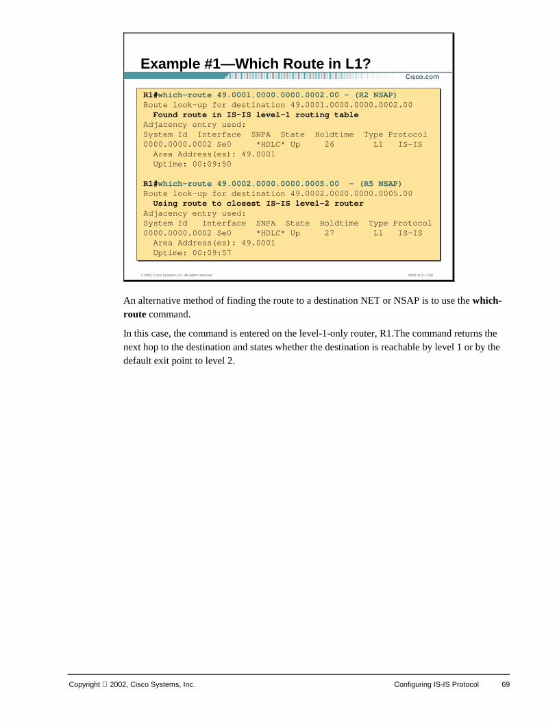
An alternative method of finding the route to a destination NET or NSAP is to use the which-route command.
In this case, the command is entered on the level-1-only router, R1.The command returns the next hop to the destination and states whether the destination is reachable by level 1 or by the default exit point to level 2.
© 2002, Cisco Systems, Inc. All rights reserved. BSCI v1.2—7-69
Example #1—Which Route in L1?
R1#which-route 49.0001.0000.0000.0002.00 - (R2 NSAP)Route look-up for destination 49.0001.0000.0000.0002.00
Found route in IS-IS level-1 routing tableAdjacency entry used:System Id Interface SNPA State Holdtime Type Protocol0000.0000.0002 Se0 *HDLC* Up 26 L1 IS-IS
Area Address(es): 49.0001Uptime: 00:09:50
R1#which-route 49.0002.0000.0000.0005.00 - (R5 NSAP)Route look-up for destination 49.0002.0000.0000.0005.00
Using route to closest IS-IS level-2 routerAdjacency entry used:System Id Interface SNPA State Holdtime Type Protocol0000.0000.0002 Se0 *HDLC* Up 27 L1 IS-IS
Area Address(es): 49.0001Uptime: 00:09:57
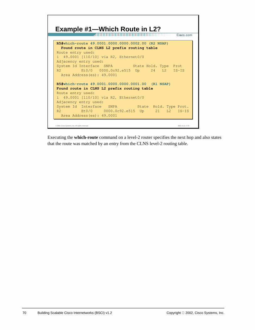
70 Building Scalable Cisco Internetworks (BSCI) v1.2 Copyright 2002, Cisco Systems, Inc.
Executing the which-route command on a level-2 router specifies the next hop and also states that the route was matched by an entry from the CLNS level-2 routing table.
© 2002, Cisco Systems, Inc. All rights reserved. BSCI v1.2—7-70
Example #1—Which Route in L2?
R5#which-route 49.0001.0000.0000.0002.00 (R2 NSAP)Found route in CLNS L2 prefix routing table
Route entry used:i 49.0001 [110/10] via R2, Ethernet0/0Adjacency entry used:System Id Interface SNPA State Hold. Type ProtR2 Et0/0 0000.0c92.e515 Up 24 L2 IS-IS
Area Address(es): 49.0001
R5#which-route 49.0001.0000.0000.0001.00 (R1 NSAP)Found route in CLNS L2 prefix routing tableRoute entry used:i 49.0001 [110/10] via R2, Ethernet0/0Adjacency entry used:System Id Interface SNPA State Hold. Type Prot.R2 Et0/0 0000.0c92.e515 Up 21 L2 IS-IS
Area Address(es): 49.0001
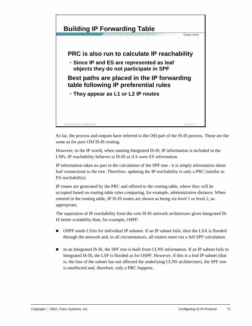
Copyright 2002, Cisco Systems, Inc. Configuring IS-IS Protocol 71
So far, the process and outputs have referred to the OSI part of the IS-IS process. These are the same as for pure OSI IS-IS routing.
However, in the IP world, when running Integrated IS-IS, IP information is included in the LSPs. IP reachability behaves in IS-IS as if it were ES information.
IP information takes no part in the calculation of the SPF tree - it is simply information about leaf connections to the tree. Therefore, updating the IP reachability is only a PRC (similar to ES reachability).
IP routes are generated by the PRC and offered to the routing table, where they will be accepted based on routing table rules comparing, for example, administrative distance. When entered in the routing table, IP IS-IS routes are shown as being via level 1 or level 2, as appropriate.
The separation of IP reachability from the core IS-IS network architecture gives Integrated IS-IS better scalability than, for example, OSPF:
! OSPF sends LSAs for individual IP subnets. If an IP subnet fails, then the LSA is flooded through the network and, in all circumstances, all routers must run a full SPF calculation.
! In an Integrated IS-IS, the SPF tree is built from CLNS information. If an IP subnet fails in Integrated IS-IS, the LSP is flooded as for OSPF. However, if this is a leaf IP subnet (that is, the loss of the subnet has not affected the underlying CLNS architecture), the SPF tree is unaffected and, therefore, only a PRC happens.
© 2002, Cisco Systems, Inc. All rights reserved. BSCI v1.2—7-71
Building IP Forwarding Table
PRC is also run to calculate IP reachability• Since IP and ES are represented as leaf
objects they do not participate in SPF
Best paths are placed in the IP forwarding table following IP preferential rules• They appear as L1 or L2 IP routes
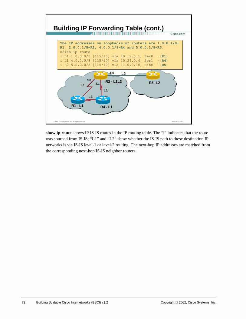
72 Building Scalable Cisco Internetworks (BSCI) v1.2 Copyright 2002, Cisco Systems, Inc.
show ip route shows IP IS-IS routes in the IP routing table. The “i” indicates that the route was sourced from IS-IS; “L1” and “L2” show whether the IS-IS path to these destination IP networks is via IS-IS level-1 or level-2 routing. The next-hop IP addresses are matched from the corresponding next-hop IS-IS neighbor routers.
© 2002, Cisco Systems, Inc. All rights reserved. BSCI v1.2—7-72
Building IP Forwarding Table (cont.)
Area 49.0001 Area 49.0002
R5- L2 R2 - L1L2
R1 - L1
L2
L1
R4 - L1
L1
L1
The IP addresses on loopbacks of routers are 1.0.0.1/8-R1, 2.0.0.1/8-R2, 4.0.0.1/8-R4 and 5.0.0.1/8-R5.R2#sh ip routei L1 1.0.0.0/8 [115/10] via 10.12.0.1, Ser0 -(R1)i L1 4.0.0.0/8 [115/10] via 10.24.0.4, Ser1 -(R4)i L2 5.0.0.0/8 [115/10] via 11.0.0.10, Eth0 -(R5)
The IP addresses on loopbacks of routers are 1.0.0.1/8-R1, 2.0.0.1/8-R2, 4.0.0.1/8-R4 and 5.0.0.1/8-R5.R2#sh ip routei L1 1.0.0.0/8 [115/10] via 10.12.0.1, Ser0 -(R1)i L1 4.0.0.0/8 [115/10] via 10.24.0.4, Ser1 -(R4)i L2 5.0.0.0/8 [115/10] via 11.0.0.10, Eth0 -(R5)
S0 S1
E0
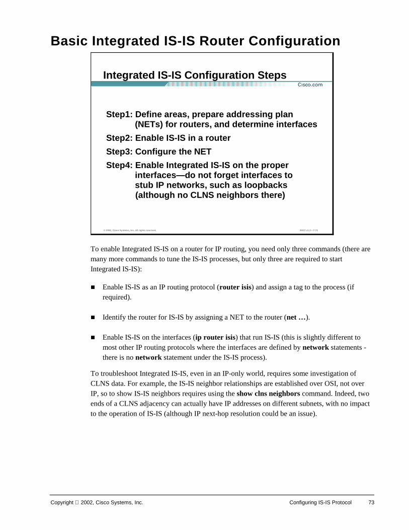
Copyright 2002, Cisco Systems, Inc. Configuring IS-IS Protocol 73
Basic Integrated IS-IS Router Configuration
To enable Integrated IS-IS on a router for IP routing, you need only three commands (there are many more commands to tune the IS-IS processes, but only three are required to start Integrated IS-IS):
! Enable IS-IS as an IP routing protocol (router isis) and assign a tag to the process (if required).
! Identify the router for IS-IS by assigning a NET to the router (net …).
! Enable IS-IS on the interfaces (ip router isis) that run IS-IS (this is slightly different to most other IP routing protocols where the interfaces are defined by network statements - there is no network statement under the IS-IS process).
To troubleshoot Integrated IS-IS, even in an IP-only world, requires some investigation of CLNS data. For example, the IS-IS neighbor relationships are established over OSI, not over IP, so to show IS-IS neighbors requires using the show clns neighbors command. Indeed, two ends of a CLNS adjacency can actually have IP addresses on different subnets, with no impact to the operation of IS-IS (although IP next-hop resolution could be an issue).
© 2002, Cisco Systems, Inc. All rights reserved. BSCI v1.2—7-74
Integrated IS-IS Configuration Steps
Step1: Define areas, prepare addressing plan (NETs) for routers, and determine interfaces
Step2: Enable IS-IS in a router
Step3: Configure the NET
Step4: Enable Integrated IS-IS on the proper interfaces—do not forget interfaces to stub IP networks, such as loopbacks(although no CLNS neighbors there)
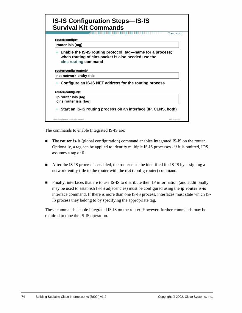
74 Building Scalable Cisco Internetworks (BSCI) v1.2 Copyright 2002, Cisco Systems, Inc.
The commands to enable Integrated IS-IS are:
! The router is-is (global configuration) command enables Integrated IS-IS on the router. Optionally, a tag can be applied to identify multiple IS-IS processes - if it is omitted, IOS assumes a tag of 0.
! After the IS-IS process is enabled, the router must be identified for IS-IS by assigning a network-entity-title to the router with the net (config-router) command.
! Finally, interfaces that are to use IS-IS to distribute their IP information (and additionally may be used to establish IS-IS adjacencies) must be configured using the ip router is-is interface command. If there is more than one IS-IS process, interfaces must state which IS-IS process they belong to by specifying the appropriate tag.
These commands enable Integrated IS-IS on the router. However, further commands may be required to tune the IS-IS operation.
© 2002, Cisco Systems, Inc. All rights reserved. BSCI v1.2—7-75
router isis [tag]router(config)#
• Enable the IS-IS routing protocol; tag—name for a process; when routing of clns packet is also needed use the clns routing command
IS-IS Configuration Steps—IS-IS Survival Kit Commands
ip router isis [tag]clns router isis [tag]
router(config-if)#
• Start an IS-IS routing process on an interface (IP, CLNS, both)
net network-entity-titlerouter(config-router)#
• Configure an IS-IS NET address for the routing process
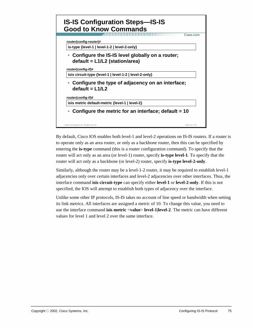
Copyright 2002, Cisco Systems, Inc. Configuring IS-IS Protocol 75
By default, Cisco IOS enables both level-1 and level-2 operations on IS-IS routers. If a router is to operate only as an area router, or only as a backbone router, then this can be specified by entering the is-type command (this is a router configuration command). To specify that the router will act only as an area (or level-1) router, specify is-type level-1. To specify that the router will act only as a backbone (or level-2) router, specify is-type level-2-only.
Similarly, although the router may be a level-1-2 router, it may be required to establish level-1 adjacencies only over certain interfaces and level-2 adjacencies over other interfaces. Thus, the interface command isis circuit-type can specify either level-1 or level-2-only. If this is not specified, the IOS will attempt to establish both types of adjacency over the interface.
Unlike some other IP protocols, IS-IS takes no account of line speed or bandwidth when setting its link metrics. All interfaces are assigned a metric of 10. To change this value, you need to use the interface command isis metric <value> level-1|level-2. The metric can have different values for level 1 and level 2 over the same interface.
© 2002, Cisco Systems, Inc. All rights reserved. BSCI v1.2—7-76
is-type {level-1 | level-1-2 | level-2-only}router(config-router)#
• Configure the IS-IS level globally on a router; default = L1/L2 (station/area)
IS-IS Configuration Steps—IS-IS Good to Know Commands
isis circuit-type {level-1 | level-1-2 | level-2-only}router(config-if)#
• Configure the type of adjacency on an interface; default = L1/L2
isis metric default-metric {level-1 | level-2}router(config-if)#
• Configure the metric for an interface; default = 10
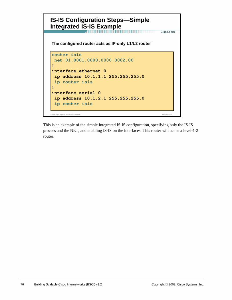
76 Building Scalable Cisco Internetworks (BSCI) v1.2 Copyright 2002, Cisco Systems, Inc.
This is an example of the simple Integrated IS-IS configuration, specifying only the IS-IS process and the NET, and enabling IS-IS on the interfaces. This router will act as a level-1-2 router.
© 2002, Cisco Systems, Inc. All rights reserved. BSCI v1.2—7-77
IS-IS Configuration Steps—Simple Integrated IS-IS Example
The configured router acts as IP-only L1/L2 router
router isisnet 01.0001.0000.0000.0002.00
!interface ethernet 0ip address 10.1.1.1 255.255.255.0ip router isis
!interface serial 0ip address 10.1.2.1 255.255.255.0ip router isis
router isisnet 01.0001.0000.0000.0002.00!interface ethernet 0ip address 10.1.1.1 255.255.255.0ip router isis!interface serial 0ip address 10.1.2.1 255.255.255.0ip router isis
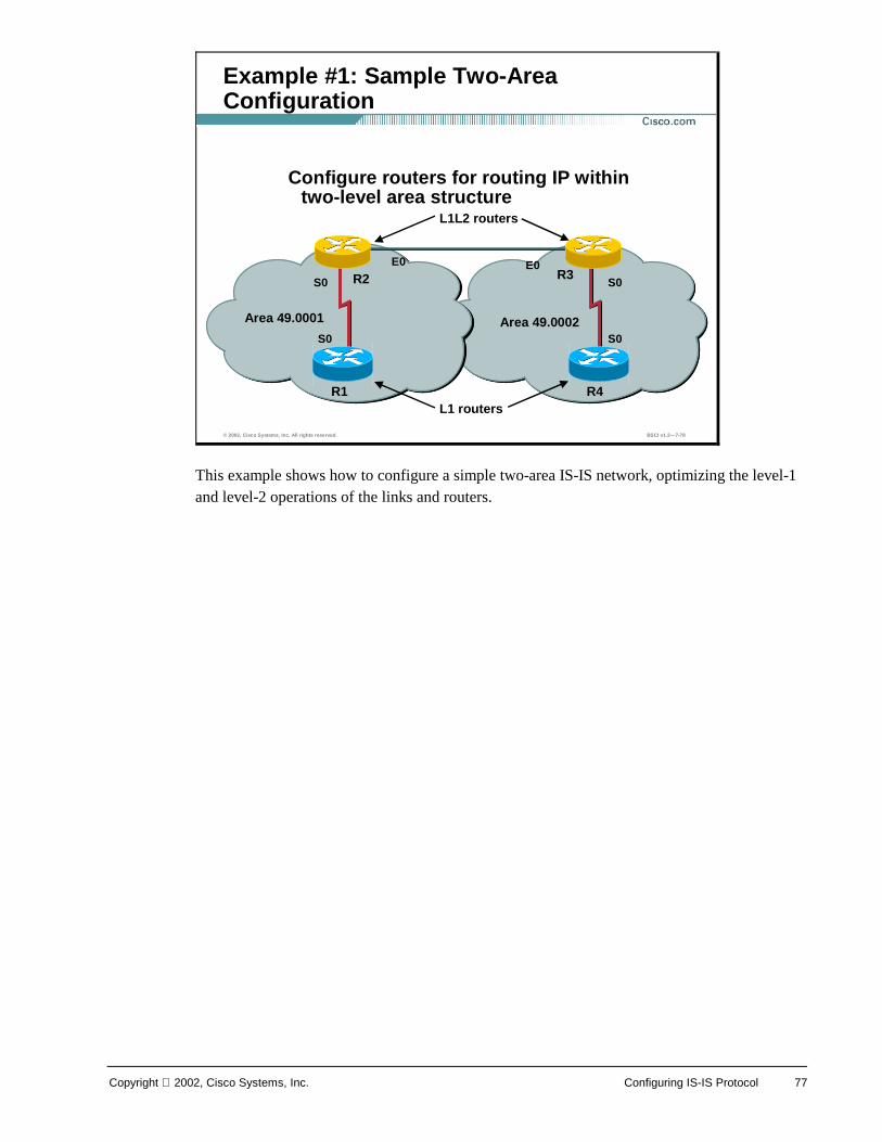
Copyright 2002, Cisco Systems, Inc. Configuring IS-IS Protocol 77
This example shows how to configure a simple two-area IS-IS network, optimizing the level-1 and level-2 operations of the links and routers.
© 2002, Cisco Systems, Inc. All rights reserved. BSCI v1.2—7-78
Example #1: Sample Two-Area Configuration
Area 49.0001 Area 49.0002
R3 R2
R1 R4
L1L2 routers
L1 routers
E0
S0
Configure routers for routing IP within two-level area structure
S0 S0
S0
E0
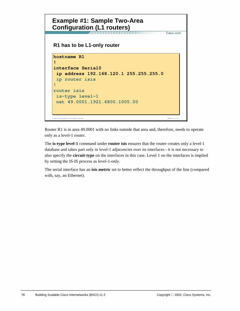
78 Building Scalable Cisco Internetworks (BSCI) v1.2 Copyright 2002, Cisco Systems, Inc.
Router R1 is in area 49.0001 with no links outside that area and, therefore, needs to operate only as a level-1 router.
The is-type level-1 command under router isis ensures that the router creates only a level-1 database and takes part only in level-1 adjacencies over its interfaces - it is not necessary to also specify the circuit-type on the interfaces in this case. Level 1 on the interfaces is implied by setting the IS-IS process as level-1-only.
The serial interface has an isis metric set to better reflect the throughput of the line (compared with, say, an Ethernet).
© 2002, Cisco Systems, Inc. All rights reserved. BSCI v1.2—7-79
Example #1: Sample Two-Area Configuration (L1 routers)
R1 has to be L1-only router
hostname R1!interface Serial0ip address 192.168.120.1 255.255.255.0ip router isis
!router isisis-type level-1net 49.0001.1921.6800.1005.00
hostname R1!interface Serial0ip address 192.168.120.1 255.255.255.0ip router isis!router isisis-type level-1net 49.0001.1921.6800.1005.00
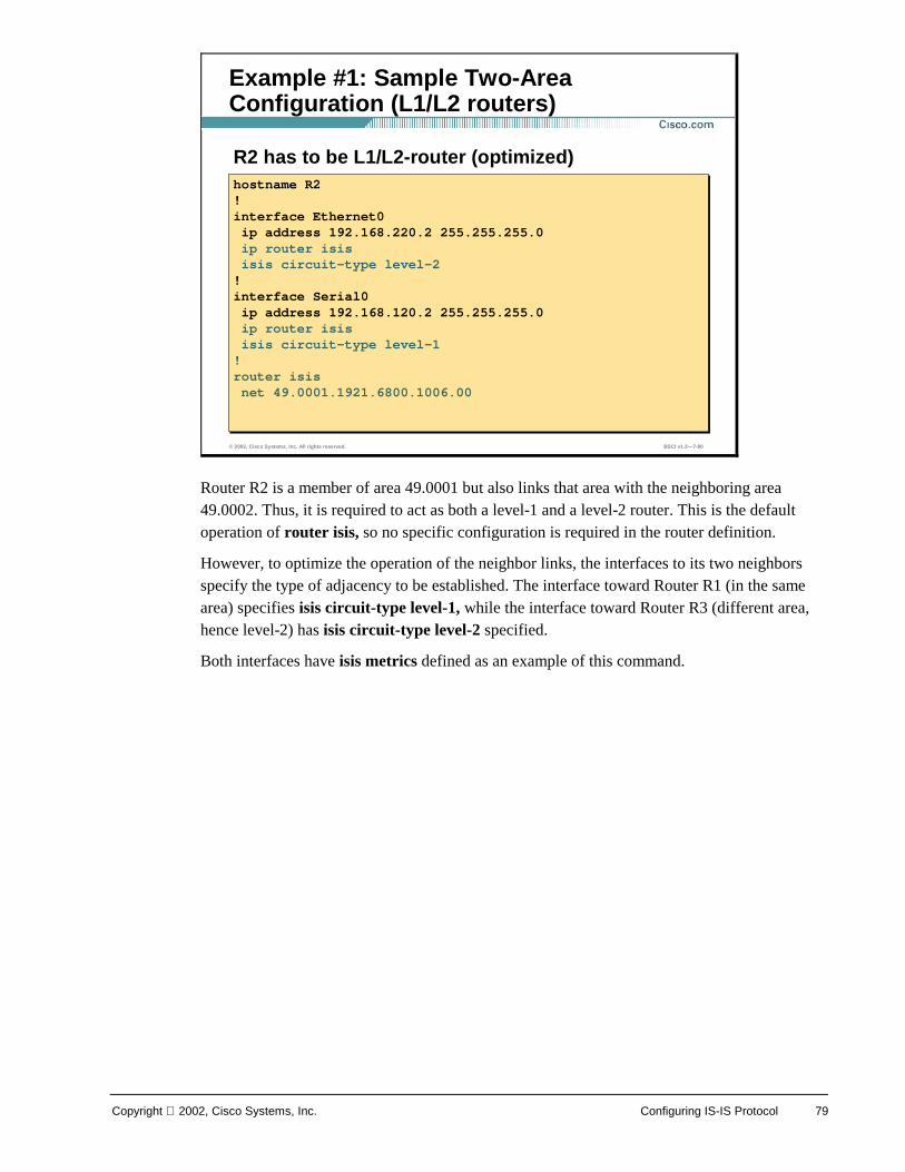
Copyright 2002, Cisco Systems, Inc. Configuring IS-IS Protocol 79
Router R2 is a member of area 49.0001 but also links that area with the neighboring area 49.0002. Thus, it is required to act as both a level-1 and a level-2 router. This is the default operation of router isis, so no specific configuration is required in the router definition.
However, to optimize the operation of the neighbor links, the interfaces to its two neighbors specify the type of adjacency to be established. The interface toward Router R1 (in the same area) specifies isis circuit-type level-1, while the interface toward Router R3 (different area, hence level-2) has isis circuit-type level-2 specified.
Both interfaces have isis metrics defined as an example of this command.
© 2002, Cisco Systems, Inc. All rights reserved. BSCI v1.2—7-80
Example #1: Sample Two-Area Configuration (L1/L2 routers)
R2 has to be L1/L2-router (optimized)hostname R2!interface Ethernet0ip address 192.168.220.2 255.255.255.0ip router isisisis circuit-type level-2!interface Serial0ip address 192.168.120.2 255.255.255.0ip router isisisis circuit-type level-1!router isisnet 49.0001.1921.6800.1006.00
hostname R2!interface Ethernet0ip address 192.168.220.2 255.255.255.0ip router isisisis circuit-type level-2!interface Serial0ip address 192.168.120.2 255.255.255.0ip router isisisis circuit-type level-1!router isisnet 49.0001.1921.6800.1006.00
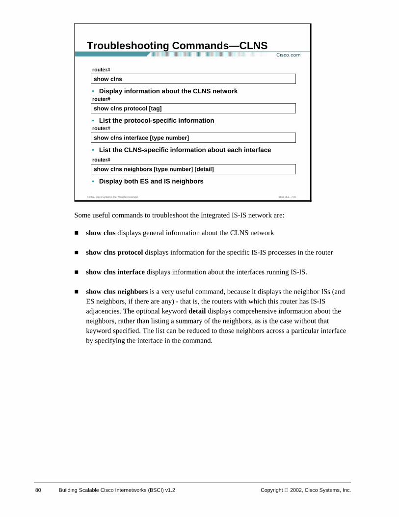
80 Building Scalable Cisco Internetworks (BSCI) v1.2 Copyright 2002, Cisco Systems, Inc.
Some useful commands to troubleshoot the Integrated IS-IS network are:
! show clns displays general information about the CLNS network
! show clns protocol displays information for the specific IS-IS processes in the router
! show clns interface displays information about the interfaces running IS-IS.
! show clns neighbors is a very useful command, because it displays the neighbor ISs (and ES neighbors, if there are any) - that is, the routers with which this router has IS-IS adjacencies. The optional keyword detail displays comprehensive information about the neighbors, rather than listing a summary of the neighbors, as is the case without that keyword specified. The list can be reduced to those neighbors across a particular interface by specifying the interface in the command.
© 2002, Cisco Systems, Inc. All rights reserved. BSCI v1.2—7-81
show clns
router#
• Display information about the CLNS network
Troubleshooting Commands—CLNS
show clns protocol [tag]
router#
• List the protocol-specific information
show clns interface [type number]
router#
• List the CLNS-specific information about each interface
show clns neighbors [type number] [detail]
router#
• Display both ES and IS neighbors
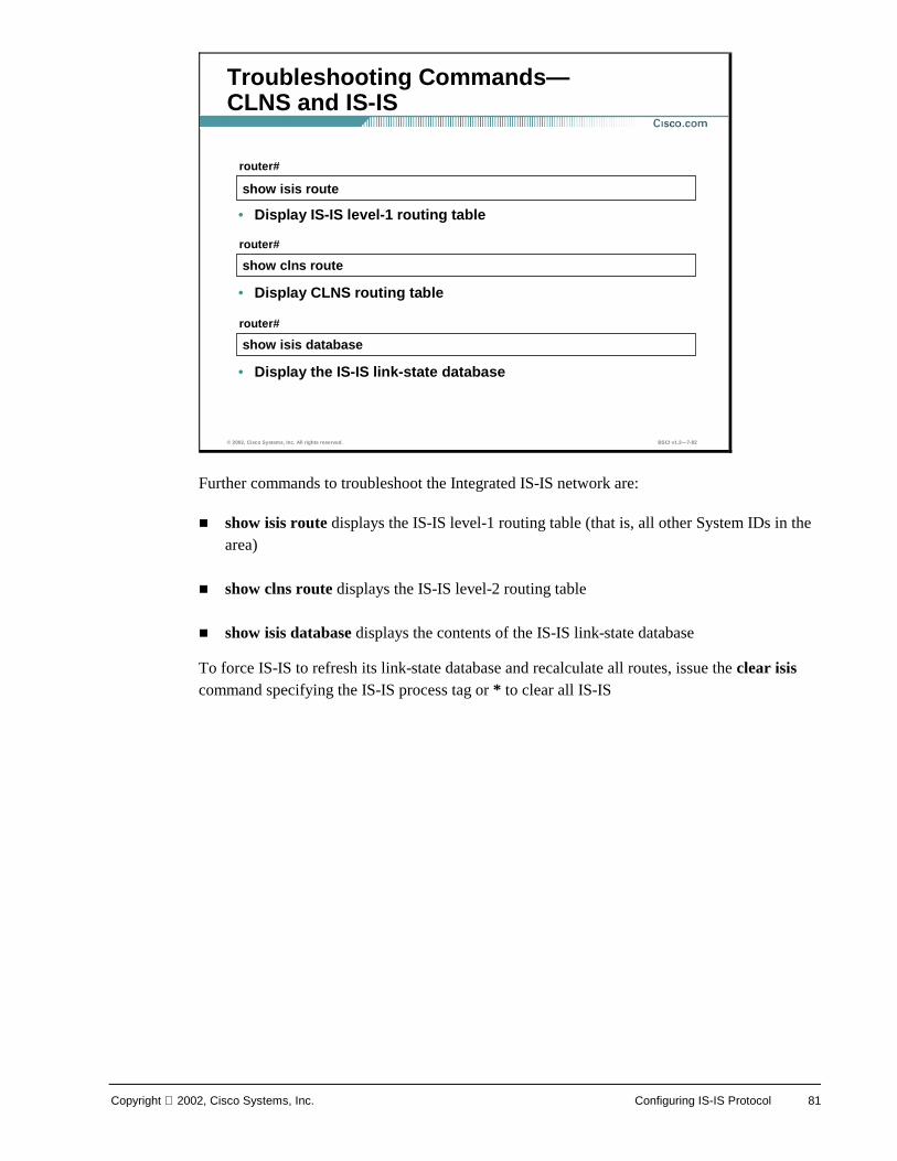
Copyright 2002, Cisco Systems, Inc. Configuring IS-IS Protocol 81
Further commands to troubleshoot the Integrated IS-IS network are:
! show isis route displays the IS-IS level-1 routing table (that is, all other System IDs in the area)
! show clns route displays the IS-IS level-2 routing table
! show isis database displays the contents of the IS-IS link-state database
To force IS-IS to refresh its link-state database and recalculate all routes, issue the clear isis command specifying the IS-IS process tag or * to clear all IS-IS
© 2002, Cisco Systems, Inc. All rights reserved. BSCI v1.2—7-82
show isis route
router#
• Display IS-IS level-1 routing table
Troubleshooting Commands—CLNS and IS-IS
show clns route
router#
• Display CLNS routing table
show isis database
router#
• Display the IS-IS link-state database
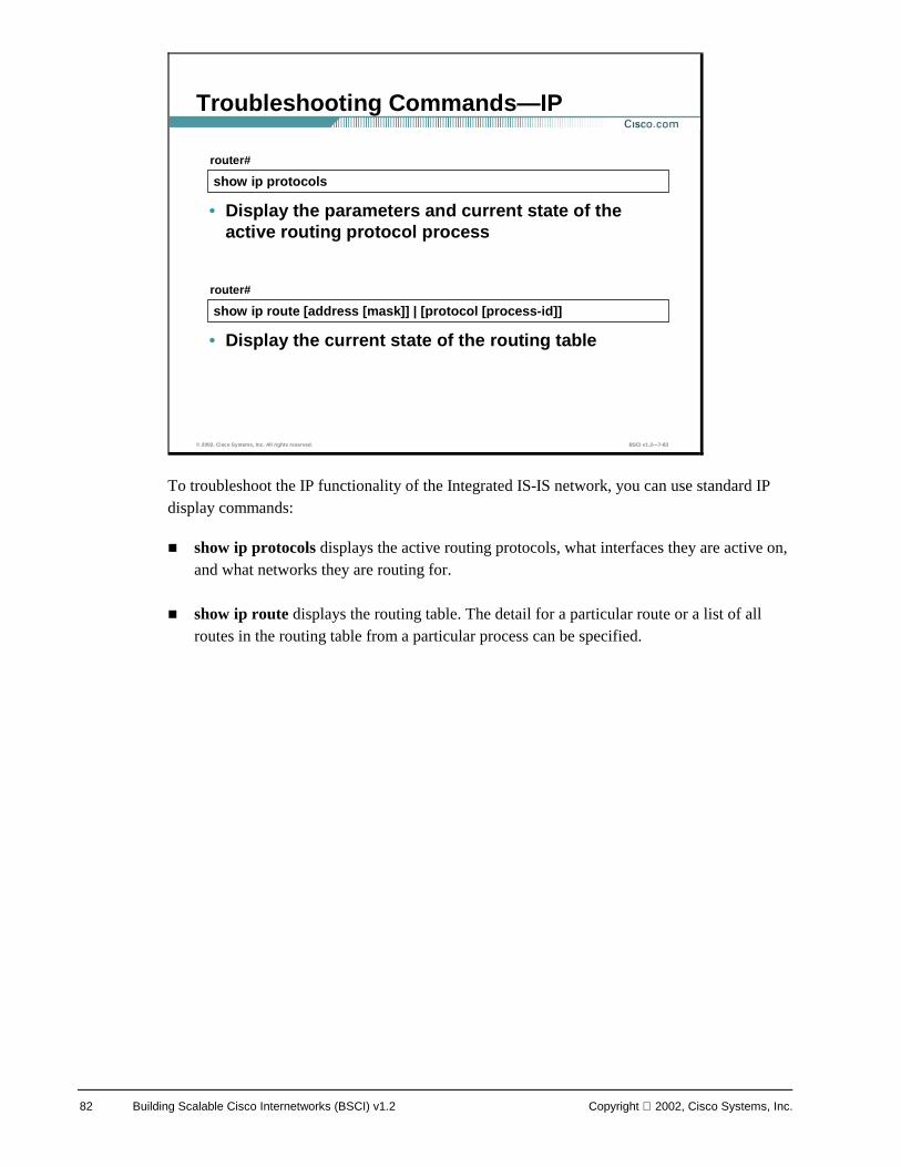
82 Building Scalable Cisco Internetworks (BSCI) v1.2 Copyright 2002, Cisco Systems, Inc.
To troubleshoot the IP functionality of the Integrated IS-IS network, you can use standard IP display commands:
! show ip protocols displays the active routing protocols, what interfaces they are active on, and what networks they are routing for.
! show ip route displays the routing table. The detail for a particular route or a list of all routes in the routing table from a particular process can be specified.
© 2002, Cisco Systems, Inc. All rights reserved. BSCI v1.2—7-83
show ip protocols
router#
• Display the parameters and current state of the active routing protocol process
Troubleshooting Commands—IP
show ip route [address [mask]] | [protocol [process-id]]
router#
• Display the current state of the routing table
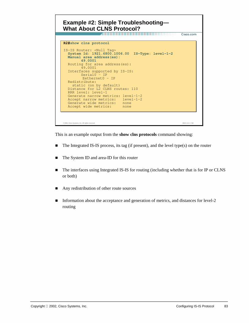
Copyright 2002, Cisco Systems, Inc. Configuring IS-IS Protocol 83
This is an example output from the show clns protocols command showing:
! The Integrated IS-IS process, its tag (if present), and the level type(s) on the router
! The System ID and area-ID for this router
! The interfaces using Integrated IS-IS for routing (including whether that is for IP or CLNS or both)
! Any redistribution of other route sources
! Information about the acceptance and generation of metrics, and distances for level-2 routing
© 2002, Cisco Systems, Inc. All rights reserved. BSCI v1.2—7-84
Example #2: Simple Troubleshooting—What About CLNS Protocol?
R2#show clns protocol
IS-IS Router: <Null Tag>System Id: 1921.6800.1006.00 IS-Type: level-1-2Manual area address(es):
49.0001Routing for area address(es):
49.0001Interfaces supported by IS-IS:
Serial0 - IPEethernet0 - IP
Redistribute:static (on by default)
Distance for L2 CLNS routes: 110RRR level: level-1Generate narrow metrics: level-1-2Accept narrow metrics: level-1-2Generate wide metrics: none Accept wide metrics: none
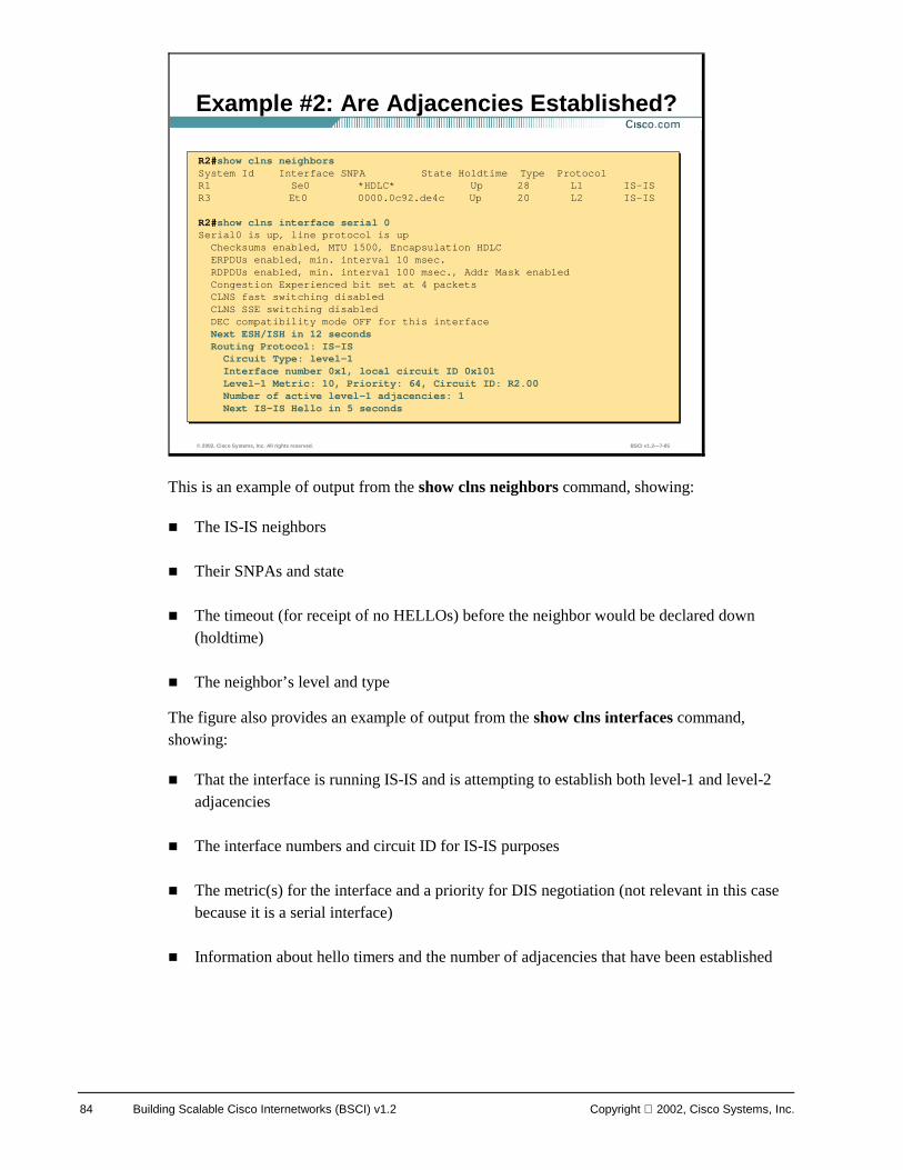
84 Building Scalable Cisco Internetworks (BSCI) v1.2 Copyright 2002, Cisco Systems, Inc.
This is an example of output from the show clns neighbors command, showing:
! The IS-IS neighbors
! Their SNPAs and state
! The timeout (for receipt of no HELLOs) before the neighbor would be declared down (holdtime)
! The neighbor’s level and type
The figure also provides an example of output from the show clns interfaces command, showing:
! That the interface is running IS-IS and is attempting to establish both level-1 and level-2 adjacencies
! The interface numbers and circuit ID for IS-IS purposes
! The metric(s) for the interface and a priority for DIS negotiation (not relevant in this case because it is a serial interface)
! Information about hello timers and the number of adjacencies that have been established
© 2002, Cisco Systems, Inc. All rights reserved. BSCI v1.2—7-85
Example #2: Are Adjacencies Established?
R2#show clns neighborsSystem Id Interface SNPA State Holdtime Type ProtocolR1 Se0 *HDLC* Up 28 L1 IS-ISR3 Et0 0000.0c92.de4c Up 20 L2 IS-IS
R2#show clns interface serial 0Serial0 is up, line protocol is up
Checksums enabled, MTU 1500, Encapsulation HDLCERPDUs enabled, min. interval 10 msec.RDPDUs enabled, min. interval 100 msec., Addr Mask enabledCongestion Experienced bit set at 4 packetsCLNS fast switching disabledCLNS SSE switching disabledDEC compatibility mode OFF for this interfaceNext ESH/ISH in 12 secondsRouting Protocol: IS-ISCircuit Type: level-1Interface number 0x1, local circuit ID 0x101Level-1 Metric: 10, Priority: 64, Circuit ID: R2.00Number of active level-1 adjacencies: 1Next IS-IS Hello in 5 seconds
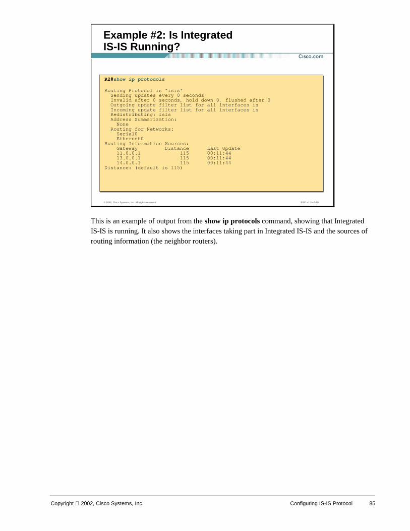
Copyright 2002, Cisco Systems, Inc. Configuring IS-IS Protocol 85
This is an example of output from the show ip protocols command, showing that Integrated IS-IS is running. It also shows the interfaces taking part in Integrated IS-IS and the sources of routing information (the neighbor routers).
© 2002, Cisco Systems, Inc. All rights reserved. BSCI v1.2—7-86
Example #2: Is Integrated IS-IS Running?
R2#show ip protocols
Routing Protocol is "isis"Sending updates every 0 secondsInvalid after 0 seconds, hold down 0, flushed after 0Outgoing update filter list for all interfaces isIncoming update filter list for all interfaces isRedistributing: isisAddress Summarization:None
Routing for Networks:Serial0Ethernet0
Routing Information Sources:Gateway Distance Last Update11.0.0.1 115 00:11:4413.0.0.1 115 00:11:4414.0.0.1 115 00:11:44
Distance: (default is 115)
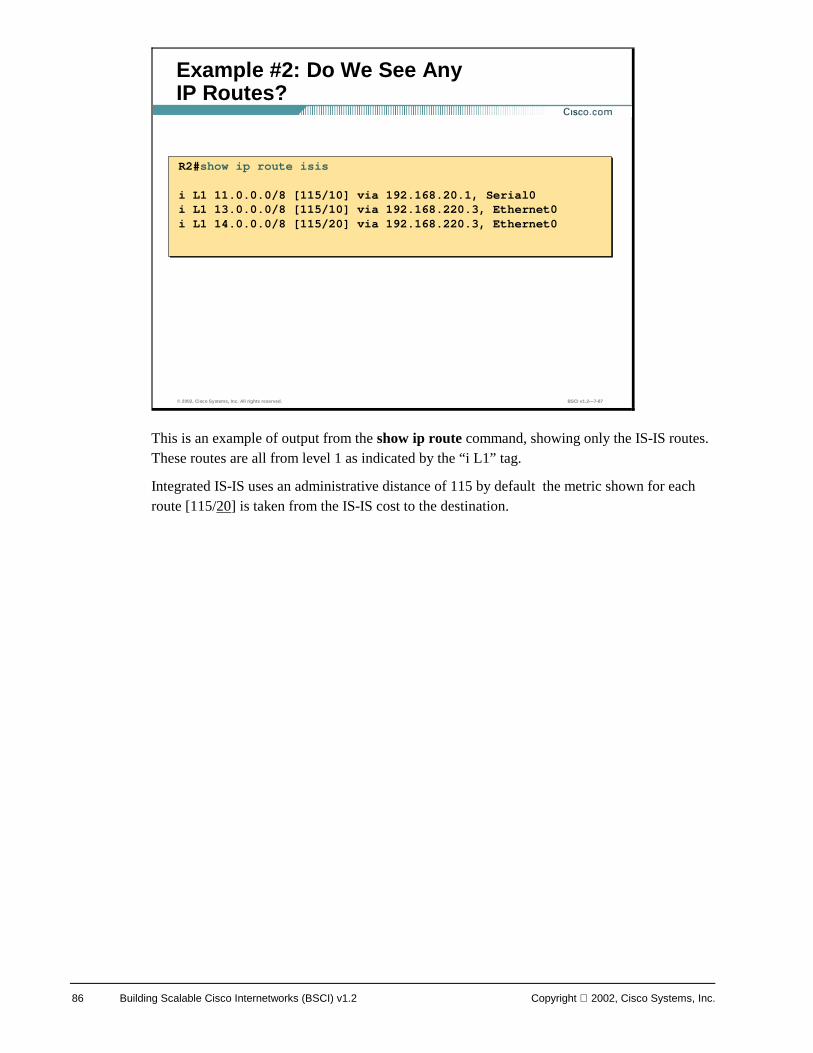
86 Building Scalable Cisco Internetworks (BSCI) v1.2 Copyright 2002, Cisco Systems, Inc.
This is an example of output from the show ip route command, showing only the IS-IS routes. These routes are all from level 1 as indicated by the “i L1” tag.
Integrated IS-IS uses an administrative distance of 115 by default the metric shown for each route [115/20] is taken from the IS-IS cost to the destination.
© 2002, Cisco Systems, Inc. All rights reserved. BSCI v1.2—7-87
Example #2: Do We See Any IP Routes?
R2#show ip route isis
i L1 11.0.0.0/8 [115/10] via 192.168.20.1, Serial0i L1 13.0.0.0/8 [115/10] via 192.168.220.3, Ethernet0i L1 14.0.0.0/8 [115/20] via 192.168.220.3, Ethernet0
R2#show ip route isis
i L1 11.0.0.0/8 [115/10] via 192.168.20.1, Serial0i L1 13.0.0.0/8 [115/10] via 192.168.220.3, Ethernet0i L1 14.0.0.0/8 [115/20] via 192.168.220.3, Ethernet0
Copyright 2002, Cisco Systems, Inc. Configuring IS-IS Protocol 87
Modeling WAN Networks in Integrated IS-IS
WANs are typically implemented as either point-to-point or point-to-multipoint, and most support multiple connections. These WANs typically do not support broadcasting and are thus classified as NBMA.
Point-to-point WANs are typically leased circuits between two routers. A point-to-point WAN has two devices attached - one at each end of the circuit. Usually such links will run Cisco HDLC or Point-to-Point Protocol (PPP). These correspond exactly to the Integrated IS-IS classification of a point-to-point network.
Note A point-to-point circuit is still regarded as an NBMA network, just as a back-to-back Ethernet connection is still a LAN. Both are examples of multiple-access networks that have only two devices attached.
Dialup networks using dial-on-demand routing (DDR) can be configured as either point-to-point or point-to-multipoint WAN implementations:
! Legacy DDR dialup connections (that is, “dialer map” statements) are NBMA (even though they may use PPP as their line protocol), because a single interface can support multiple destinations.
! Dialer profiles and dialer virtual profiles are point-to-point connections (one Dialer Profile equals one remote profile), but these can suffer from the same loss-of-neighbor delays as NBMA networks.
© 2002, Cisco Systems, Inc. All rights reserved. BSCI v1.2—7-89
Integrated IS-IS over WANs
Three categories:• Point-to-Point leased circuits
–Few or no issues for IS-IS
• Dialup
–Avoid IS-IS over dialup except for backup
• Switched WAN
–Various design options exist for NBMA networks

88 Building Scalable Cisco Internetworks (BSCI) v1.2 Copyright 2002, Cisco Systems, Inc.
! Dialer virtual profiles are point-to-point connections where the interface drops immediately if the remote end disconnects, leading to faster neighbor-loss detection and faster convergence.
Dial interfaces are not dealt with in this lesson. As a general rule, you should avoid IS-IS over dialup, except to provide dial-backup functionality.
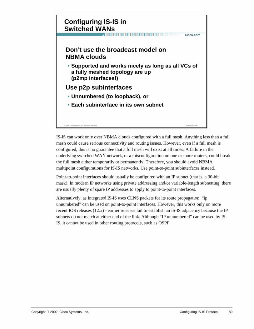
Copyright 2002, Cisco Systems, Inc. Configuring IS-IS Protocol 89
IS-IS can work only over NBMA clouds configured with a full mesh. Anything less than a full mesh could cause serious connectivity and routing issues. However, even if a full mesh is configured, this is no guarantee that a full mesh will exist at all times. A failure in the underlying switched WAN network, or a misconfiguration on one or more routers, could break the full mesh either temporarily or permanently. Therefore, you should avoid NBMA multipoint configurations for IS-IS networks. Use point-to-point subinterfaces instead.
Point-to-point interfaces should usually be configured with an IP subnet (that is, a 30-bit mask). In modern IP networks using private addressing and/or variable-length subnetting, there are usually plenty of spare IP addresses to apply to point-to-point interfaces.
Alternatively, as Integrated IS-IS uses CLNS packets for its route propagation, “ip unnumbered” can be used on point-to-point interfaces. However, this works only on more recent IOS releases (12.x) - earlier releases fail to establish an IS-IS adjacency because the IP subnets do not match at either end of the link. Although “IP unnumbered” can be used by IS-IS, it cannot be used in other routing protocols, such as OSPF.
© 2002, Cisco Systems, Inc. All rights reserved. BSCI v1.2—7-90
Configuring IS-IS in Switched WANs
Don’t use the broadcast model on NBMA clouds• Supported and works nicely as long as all VCs of
a fully meshed topology are up (p2mp interfaces!)
Use p2p subinterfaces• Unnumbered (to loopback), or
• Each subinterface in its own subnet
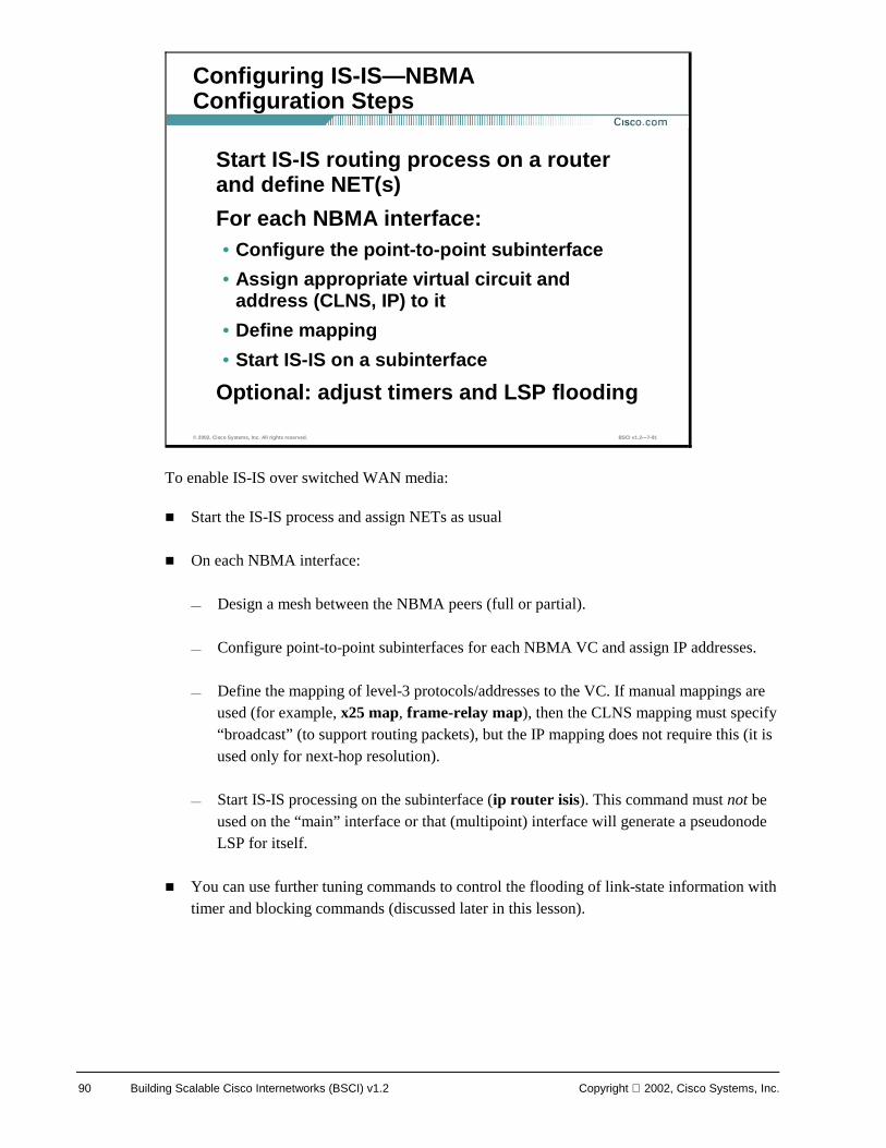
90 Building Scalable Cisco Internetworks (BSCI) v1.2 Copyright 2002, Cisco Systems, Inc.
To enable IS-IS over switched WAN media:
! Start the IS-IS process and assign NETs as usual
! On each NBMA interface:
— Design a mesh between the NBMA peers (full or partial).
— Configure point-to-point subinterfaces for each NBMA VC and assign IP addresses.
— Define the mapping of level-3 protocols/addresses to the VC. If manual mappings are used (for example, x25 map, frame-relay map), then the CLNS mapping must specify “broadcast” (to support routing packets), but the IP mapping does not require this (it is used only for next-hop resolution).
— Start IS-IS processing on the subinterface (ip router isis). This command must not be used on the “main” interface or that (multipoint) interface will generate a pseudonode LSP for itself.
! You can use further tuning commands to control the flooding of link-state information with timer and blocking commands (discussed later in this lesson).
© 2002, Cisco Systems, Inc. All rights reserved. BSCI v1.2—7-91
Configuring IS-IS—NBMA Configuration Steps
Start IS-IS routing process on a router and define NET(s)
For each NBMA interface:• Configure the point-to-point subinterface
• Assign appropriate virtual circuit and address (CLNS, IP) to it
• Define mapping
• Start IS-IS on a subinterface
Optional: adjust timers and LSP flooding
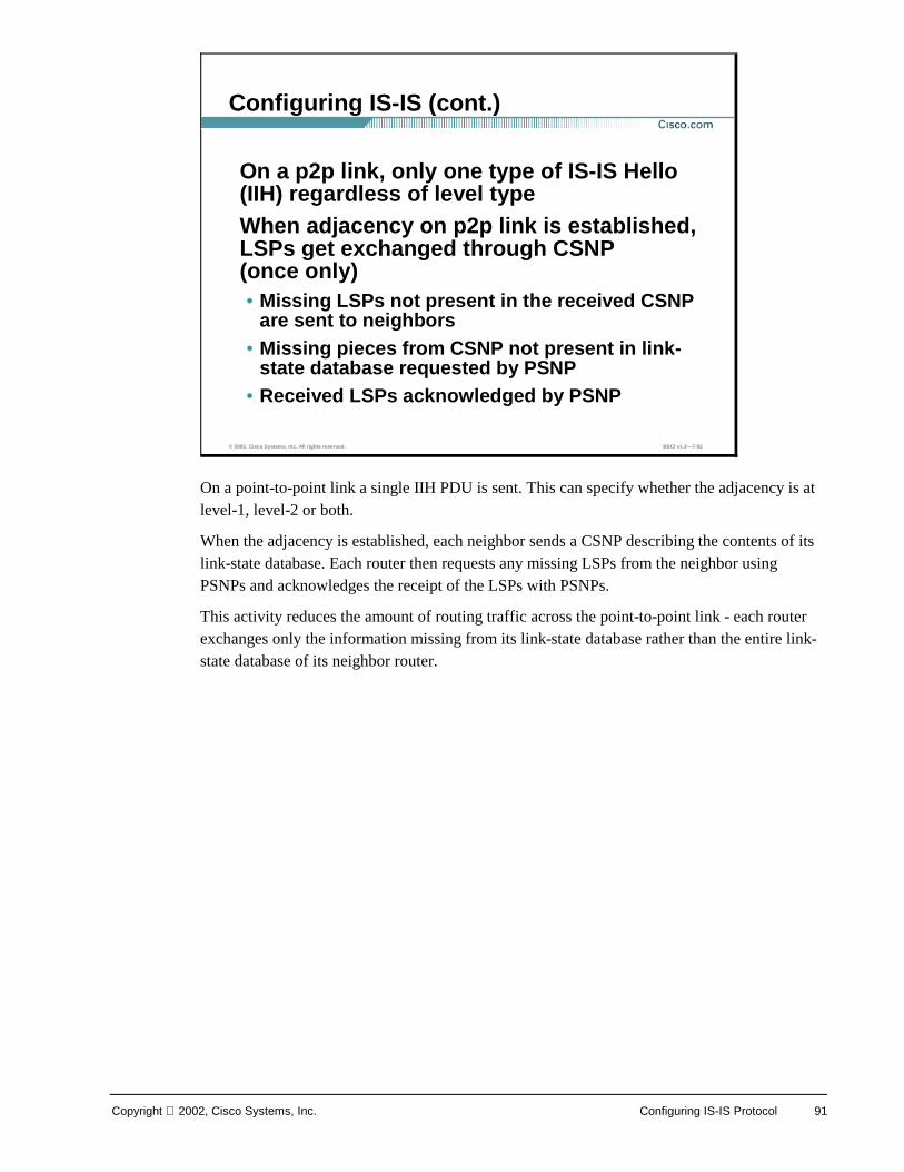
Copyright 2002, Cisco Systems, Inc. Configuring IS-IS Protocol 91
On a point-to-point link a single IIH PDU is sent. This can specify whether the adjacency is at level-1, level-2 or both.
When the adjacency is established, each neighbor sends a CSNP describing the contents of its link-state database. Each router then requests any missing LSPs from the neighbor using PSNPs and acknowledges the receipt of the LSPs with PSNPs.
This activity reduces the amount of routing traffic across the point-to-point link - each router exchanges only the information missing from its link-state database rather than the entire link-state database of its neighbor router.
© 2002, Cisco Systems, Inc. All rights reserved. BSCI v1.2—7-92
Configuring IS-IS (cont.)
On a p2p link, only one type of IS-IS Hello (IIH) regardless of level typeWhen adjacency on p2p link is established, LSPs get exchanged through CSNP (once only)• Missing LSPs not present in the received CSNP
are sent to neighbors• Missing pieces from CSNP not present in link-
state database requested by PSNP• Received LSPs acknowledged by PSNP
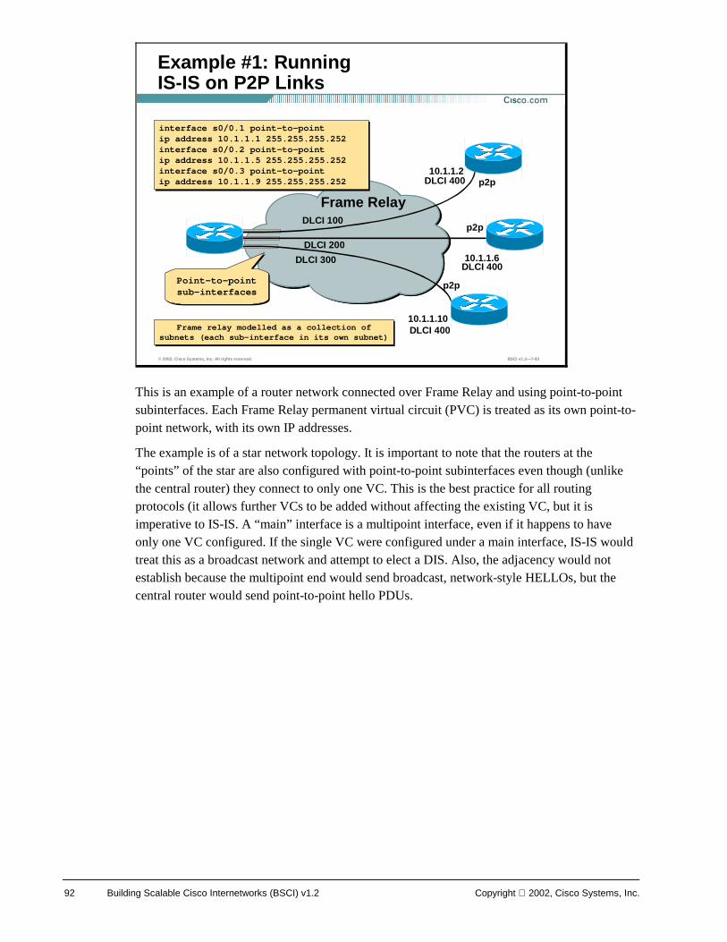
92 Building Scalable Cisco Internetworks (BSCI) v1.2 Copyright 2002, Cisco Systems, Inc.
This is an example of a router network connected over Frame Relay and using point-to-point subinterfaces. Each Frame Relay permanent virtual circuit (PVC) is treated as its own point-to-point network, with its own IP addresses.
The example is of a star network topology. It is important to note that the routers at the “points” of the star are also configured with point-to-point subinterfaces even though (unlike the central router) they connect to only one VC. This is the best practice for all routing protocols (it allows further VCs to be added without affecting the existing VC, but it is imperative to IS-IS. A “main” interface is a multipoint interface, even if it happens to have only one VC configured. If the single VC were configured under a main interface, IS-IS would treat this as a broadcast network and attempt to elect a DIS. Also, the adjacency would not establish because the multipoint end would send broadcast, network-style HELLOs, but the central router would send point-to-point hello PDUs.
© 2002, Cisco Systems, Inc. All rights reserved. BSCI v1.2—7-93
Example #1: Running IS-IS on P2P Links
R4
R1
R2
R3
Frame Relay
10.1.1.2
10.1.1.6
10.1.1.10
DLCI 100
DLCI 200
DLCI 300
DLCI 400
DLCI 400
DLCI 400
p2p
p2p
p2p
Frame relay modelled as a collection of subnets (each sub-interface in its own subnet)
Frame relay modelled as a collection of subnets (each sub-interface in its own subnet)
interface s0/0.1 point-to-pointip address 10.1.1.1 255.255.255.252interface s0/0.2 point-to-pointip address 10.1.1.5 255.255.255.252interface s0/0.3 point-to-pointip address 10.1.1.9 255.255.255.252
interface s0/0.1 point-to-pointip address 10.1.1.1 255.255.255.252interface s0/0.2 point-to-pointip address 10.1.1.5 255.255.255.252interface s0/0.3 point-to-pointip address 10.1.1.9 255.255.255.252
Point-to-point sub-interfaces
Point-to-point sub-interfaces
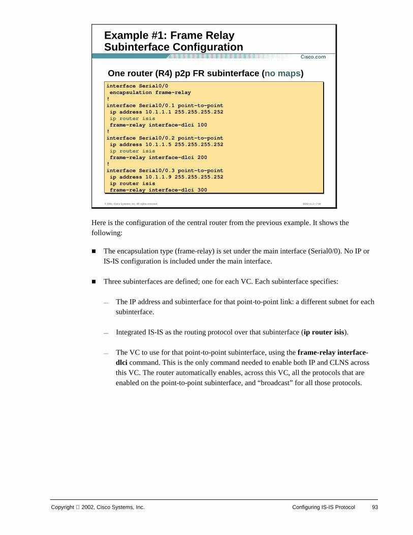
Copyright 2002, Cisco Systems, Inc. Configuring IS-IS Protocol 93
Here is the configuration of the central router from the previous example. It shows the following:
! The encapsulation type (frame-relay) is set under the main interface (Serial0/0). No IP or IS-IS configuration is included under the main interface.
! Three subinterfaces are defined; one for each VC. Each subinterface specifies:
— The IP address and subinterface for that point-to-point link: a different subnet for each subinterface.
— Integrated IS-IS as the routing protocol over that subinterface (ip router isis).
— The VC to use for that point-to-point subinterface, using the frame-relay interface-dlci command. This is the only command needed to enable both IP and CLNS across this VC. The router automatically enables, across this VC, all the protocols that are enabled on the point-to-point subinterface, and “broadcast” for all those protocols.
© 2002, Cisco Systems, Inc. All rights reserved. BSCI v1.2—7-94
Example #1: Frame RelaySubinterface Configuration
One router (R4) p2p FR subinterface (no maps)interface Serial0/0encapsulation frame-relay!interface Serial0/0.1 point-to-pointip address 10.1.1.1 255.255.255.252ip router isisframe-relay interface-dlci 100!interface Serial0/0.2 point-to-pointip address 10.1.1.5 255.255.255.252ip router isisframe-relay interface-dlci 200!interface Serial0/0.3 point-to-pointip address 10.1.1.9 255.255.255.252ip router isisframe-relay interface-dlci 300
interface Serial0/0encapsulation frame-relay!interface Serial0/0.1 point-to-pointip address 10.1.1.1 255.255.255.252ip router isisframe-relay interface-dlci 100!interface Serial0/0.2 point-to-pointip address 10.1.1.5 255.255.255.252ip router isisframe-relay interface-dlci 200!interface Serial0/0.3 point-to-pointip address 10.1.1.9 255.255.255.252ip router isisframe-relay interface-dlci 300
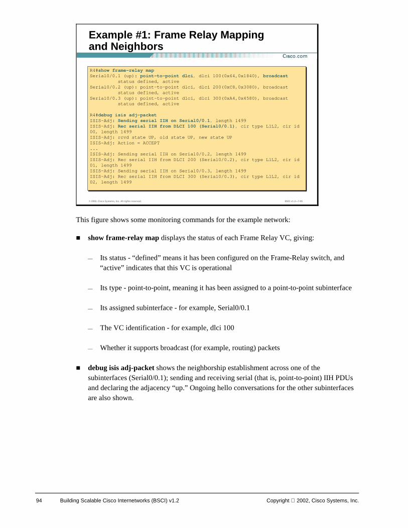
94 Building Scalable Cisco Internetworks (BSCI) v1.2 Copyright 2002, Cisco Systems, Inc.
This figure shows some monitoring commands for the example network:
! show frame-relay map displays the status of each Frame Relay VC, giving:
— Its status - “defined” means it has been configured on the Frame-Relay switch, and “active” indicates that this VC is operational
— Its type - point-to-point, meaning it has been assigned to a point-to-point subinterface
— Its assigned subinterface - for example, Serial0/0.1
— The VC identification - for example, dlci 100
— Whether it supports broadcast (for example, routing) packets
! debug isis adj-packet shows the neighborship establishment across one of the subinterfaces (Serial0/0.1); sending and receiving serial (that is, point-to-point) IIH PDUs and declaring the adjacency “up.” Ongoing hello conversations for the other subinterfaces are also shown.
© 2002, Cisco Systems, Inc. All rights reserved. BSCI v1.2—7-95
Example #1: Frame Relay Mappingand Neighbors
R4#show frame-relay mapSerial0/0.1 (up): point-to-point dlci, dlci 100(0x64,0x1840), broadcast
status defined, activeSerial0/0.2 (up): point-to-point dlci, dlci 200(0xC8,0x3080), broadcast
status defined, activeSerial0/0.3 (up): point-to-point dlci, dlci 300(0xA4,0x4580), broadcast
status defined, active
R4#debug isis adj-packetISIS-Adj: Sending serial IIH on Serial0/0.1, length 1499ISIS-Adj: Rec serial IIH from DLCI 100 (Serial0/0.1), cir type L1L2, cir id 00, length 1499ISIS-Adj: rcvd state UP, old state UP, new state UPISIS-Adj: Action = ACCEPT...ISIS-Adj: Sending serial IIH on Serial0/0.2, length 1499ISIS-Adj: Rec serial IIH from DLCI 200 (Serial0/0.2), cir type L1L2, cir id 01, length 1499ISIS-Adj: Sending serial IIH on Serial0/0.3, length 1499ISIS-Adj: Rec serial IIH from DLCI 300 (Serial0/0.3), cir type L1L2, cir id02, length 1499
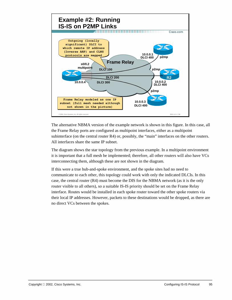
Copyright 2002, Cisco Systems, Inc. Configuring IS-IS Protocol 95
The alternative NBMA version of the example network is shown in this figure. In this case, all the Frame Relay ports are configured as multipoint interfaces, either as a multipoint subinterface (on the central router R4) or, possibly, the “main” interfaces on the other routers. All interfaces share the same IP subnet.
The diagram shows the star topology from the previous example. In a multipoint environment it is important that a full mesh be implemented; therefore, all other routers will also have VCs interconnecting them, although these are not shown in the diagram.
If this were a true hub-and-spoke environment, and the spoke sites had no need to communicate to each other, this topology could work with only the indicated DLCIs. In this case, the central router (R4) must become the DIS for the NBMA network (as it is the only router visible to all others), so a suitable IS-IS priority should be set on the Frame Relay interface. Routes would be installed in each spoke router toward the other spoke routers via their local IP addresses. However, packets to these destinations would be dropped, as there are no direct VCs between the spokes.
© 2002, Cisco Systems, Inc. All rights reserved. BSCI v1.2—7-96
Example #2: Running IS-IS on P2MP Links
R1
R2
R3
Frame Relays0/0.2multipoint
10.0.0.4
10.0.0.1
10.0.0.2
10.0.0.3
DLCI 100
DLCI 200
DLCI 300
DLCI 400
DLCI 400
DLCI 400
p2mp
p2mp
p2mp
Outgoing (locally significant) DLCI to
which remote IP address (Inverse ARP) and CLNS protocols are mapped
Outgoing (locally significant) DLCI to
which remote IP address (Inverse ARP) and CLNS protocols are mapped
Frame Relay modeled as one IP subnet (full mesh needed although
not shown in the picture)
Frame Relay modeled as one IP subnet (full mesh needed although
not shown in the picture)
R4
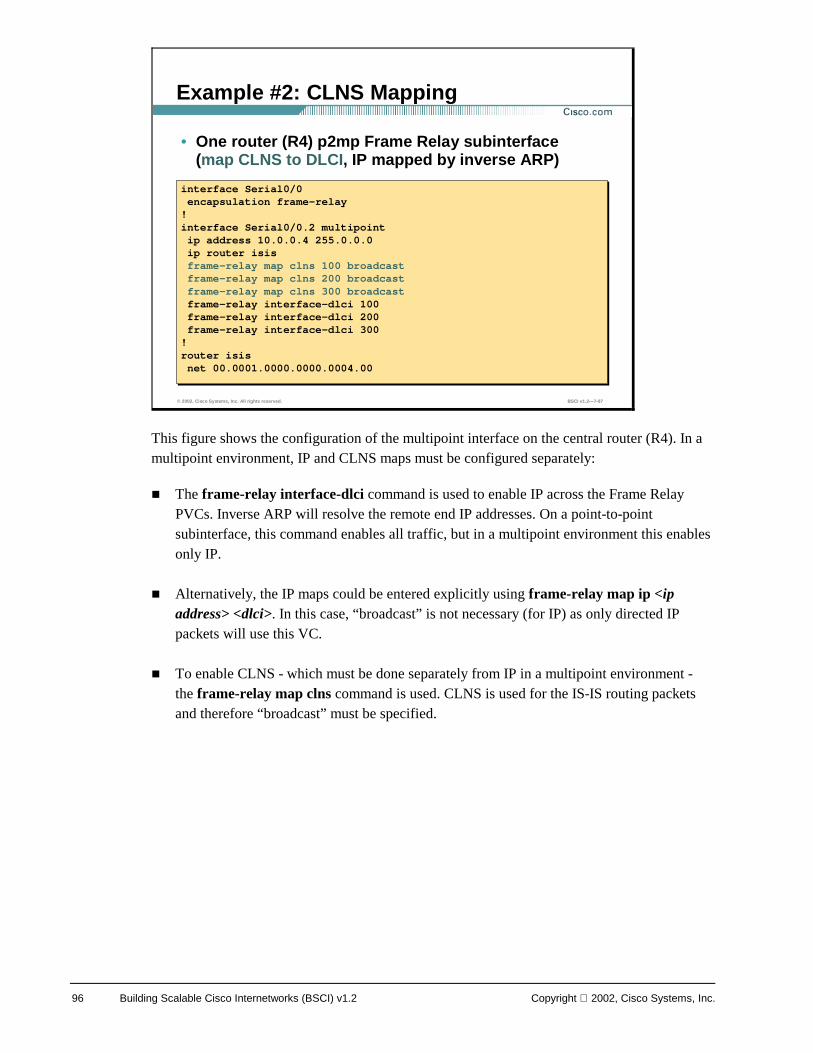
96 Building Scalable Cisco Internetworks (BSCI) v1.2 Copyright 2002, Cisco Systems, Inc.
This figure shows the configuration of the multipoint interface on the central router (R4). In a multipoint environment, IP and CLNS maps must be configured separately:
! The frame-relay interface-dlci command is used to enable IP across the Frame Relay PVCs. Inverse ARP will resolve the remote end IP addresses. On a point-to-point subinterface, this command enables all traffic, but in a multipoint environment this enables only IP.
! Alternatively, the IP maps could be entered explicitly using frame-relay map ip <ip address> <dlci>. In this case, “broadcast” is not necessary (for IP) as only directed IP packets will use this VC.
! To enable CLNS - which must be done separately from IP in a multipoint environment - the frame-relay map clns command is used. CLNS is used for the IS-IS routing packets and therefore “broadcast” must be specified.
© 2002, Cisco Systems, Inc. All rights reserved. BSCI v1.2—7-97
Example #2: CLNS Mapping
interface Serial0/0encapsulation frame-relay!interface Serial0/0.2 multipointip address 10.0.0.4 255.0.0.0ip router isisframe-relay map clns 100 broadcastframe-relay map clns 200 broadcastframe-relay map clns 300 broadcastframe-relay interface-dlci 100frame-relay interface-dlci 200frame-relay interface-dlci 300!router isisnet 00.0001.0000.0000.0004.00
interface Serial0/0encapsulation frame-relay!interface Serial0/0.2 multipointip address 10.0.0.4 255.0.0.0ip router isisframe-relay map clns 100 broadcastframe-relay map clns 200 broadcastframe-relay map clns 300 broadcastframe-relay interface-dlci 100frame-relay interface-dlci 200frame-relay interface-dlci 300!router isisnet 00.0001.0000.0000.0004.00
• One router (R4) p2mp Frame Relay subinterface (map CLNS to DLCI, IP mapped by inverse ARP)
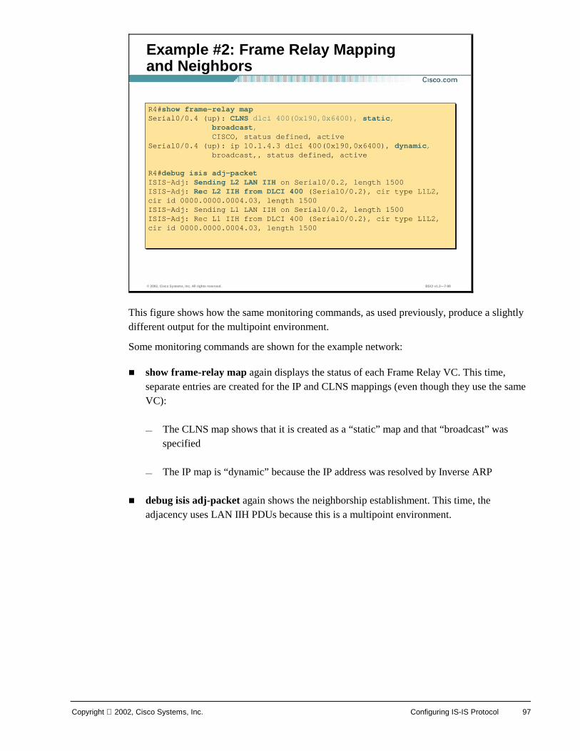
Copyright 2002, Cisco Systems, Inc. Configuring IS-IS Protocol 97
This figure shows how the same monitoring commands, as used previously, produce a slightly different output for the multipoint environment.
Some monitoring commands are shown for the example network:
! show frame-relay map again displays the status of each Frame Relay VC. This time, separate entries are created for the IP and CLNS mappings (even though they use the same VC):
— The CLNS map shows that it is created as a “static” map and that “broadcast” was specified
— The IP map is “dynamic” because the IP address was resolved by Inverse ARP
! debug isis adj-packet again shows the neighborship establishment. This time, the adjacency uses LAN IIH PDUs because this is a multipoint environment.
© 2002, Cisco Systems, Inc. All rights reserved. BSCI v1.2—7-98
Example #2: Frame Relay Mappingand Neighbors
R4#show frame-relay mapSerial0/0.4 (up): CLNS dlci 400(0x190,0x6400), static,
broadcast,CISCO, status defined, active
Serial0/0.4 (up): ip 10.1.4.3 dlci 400(0x190,0x6400), dynamic,broadcast,, status defined, active
R4#debug isis adj-packetISIS-Adj: Sending L2 LAN IIH on Serial0/0.2, length 1500ISIS-Adj: Rec L2 IIH from DLCI 400 (Serial0/0.2), cir type L1L2, cir id 0000.0000.0004.03, length 1500ISIS-Adj: Sending L1 LAN IIH on Serial0/0.2, length 1500ISIS-Adj: Rec L1 IIH from DLCI 400 (Serial0/0.2), cir type L1L2, cir id 0000.0000.0004.03, length 1500
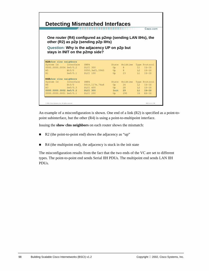
98 Building Scalable Cisco Internetworks (BSCI) v1.2 Copyright 2002, Cisco Systems, Inc.
An example of a misconfiguration is shown. One end of a link (R2) is specified as a point-to-point subinterface, but the other (R4) is using a point-to-multipoint interface.
Issuing the show clns neighbors on each router shows the mismatch:
! R2 (the point-to-point end) shows the adjacency as “up”
! R4 (the multipoint end), the adjacency is stuck in the init state
The misconfiguration results from the fact that the two ends of the VC are set to different types. The point-to-point end sends Serial IIH PDUs. The multipoint end sends LAN IIH PDUs.
© 2002, Cisco Systems, Inc. All rights reserved. BSCI v1.2—7-99
Detecting Mismatched Interfaces
One router (R4) configured as p2mp (sending LAN IIHs), the other (R2) as p2p (sending p2p IIHs)
Question: Why is the adjacency UP on p2p but stays in INIT on the p2mp side?
R2#show clns neighborsSystem Id Interface SNPA State Holdtime Type Protocol0000.0000.0004 Se0/0.2 DLCI 300 Up 8 L1 IS-ISR5 Et0/0 0050.3ef1.5960 Up 8 L2 IS-ISR1 Se0/0.1 DLCI 100 Up 23 L1 IS-IS
R4#show clns neighborsSystem Id Interface SNPA State Holdtime Type ProtocolR6 Et0/0 0010.117e.74a8 Up 26 L2 IS-ISR3 Se0/0.3 DLCI 400 Up 28 L2 IS-IS0000.0000.0002 Se0/0.2 DLCI 300 Init 29 L1 IS-IS0000.0000.0001 Se0/0.1 DLCI 200 Up 290 IS ES-IS
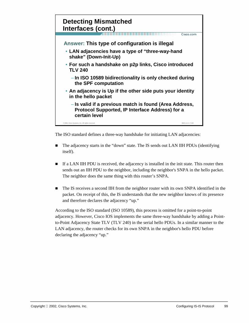
Copyright 2002, Cisco Systems, Inc. Configuring IS-IS Protocol 99
The ISO standard defines a three-way handshake for initiating LAN adjacencies:
! The adjacency starts in the “down” state. The IS sends out LAN IIH PDUs (identifying itself).
! If a LAN IIH PDU is received, the adjacency is installed in the init state. This router then sends out an IIH PDU to the neighbor, including the neighbor's SNPA in the hello packet. The neighbor does the same thing with this router’s SNPA.
! The IS receives a second IIH from the neighbor router with its own SNPA identified in the packet. On receipt of this, the IS understands that the new neighbor knows of its presence and therefore declares the adjacency “up.”
According to the ISO standard (ISO 10589), this process is omitted for a point-to-point adjacency. However, Cisco IOS implements the same three-way handshake by adding a Point-to-Point Adjacency State TLV (TLV 240) in the serial hello PDUs. In a similar manner to the LAN adjacency, the router checks for its own SNPA in the neighbor's hello PDU before declaring the adjacency “up.”
© 2002, Cisco Systems, Inc. All rights reserved. BSCI v1.2—7-100
Detecting Mismatched Interfaces (cont.)
Answer: This type of configuration is illegal• LAN adjacencies have a type of “three-way-hand
shake" (Down-Init-Up)
• For such a handshake on p2p links, Cisco introduced TLV 240
– In ISO 10589 bidirectionality is only checked during the SPF computation
• An adjacency is Up if the other side puts your identity in the hello packet
– Is valid if a previous match is found (Area Address, Protocol Supported, IP Interface Address) for a certain level
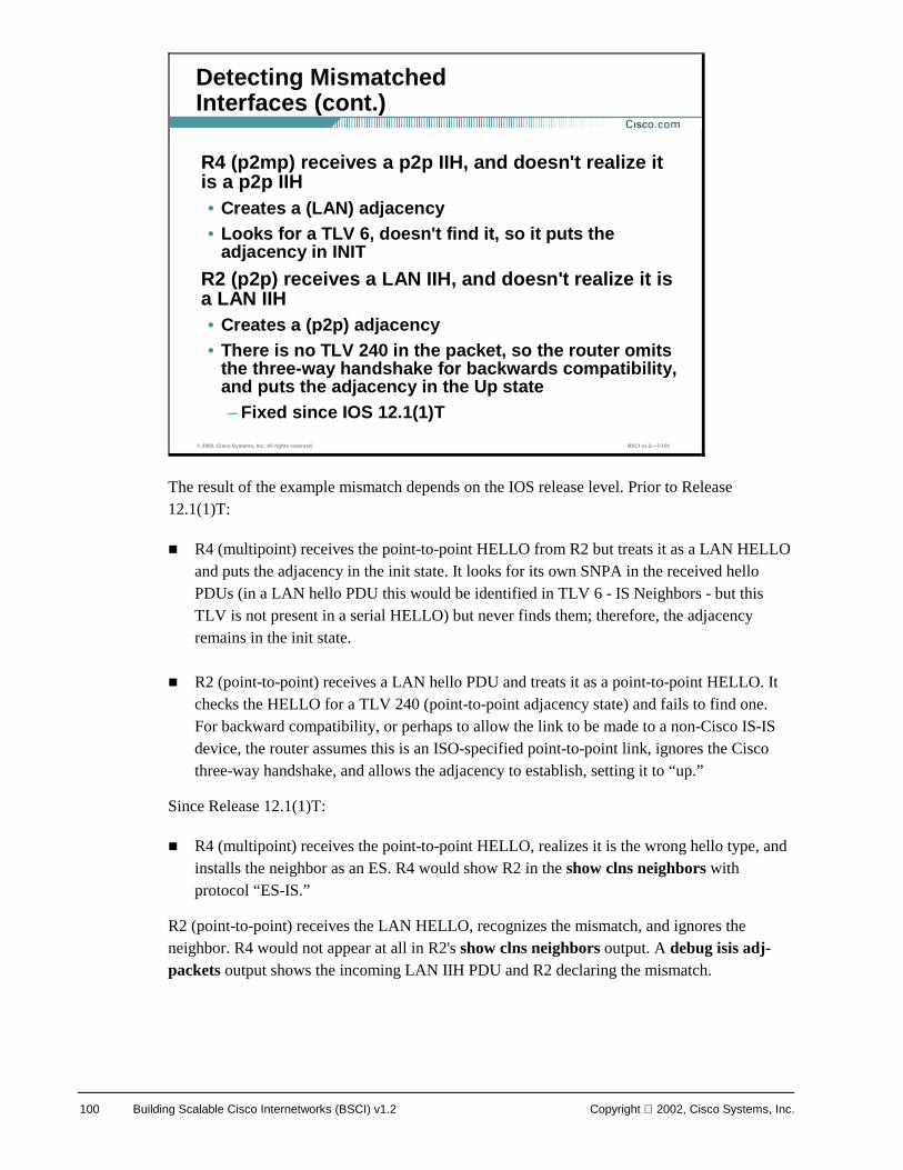
100 Building Scalable Cisco Internetworks (BSCI) v1.2 Copyright 2002, Cisco Systems, Inc.
The result of the example mismatch depends on the IOS release level. Prior to Release 12.1(1)T:
! R4 (multipoint) receives the point-to-point HELLO from R2 but treats it as a LAN HELLO and puts the adjacency in the init state. It looks for its own SNPA in the received hello PDUs (in a LAN hello PDU this would be identified in TLV 6 - IS Neighbors - but this TLV is not present in a serial HELLO) but never finds them; therefore, the adjacency remains in the init state.
! R2 (point-to-point) receives a LAN hello PDU and treats it as a point-to-point HELLO. It checks the HELLO for a TLV 240 (point-to-point adjacency state) and fails to find one. For backward compatibility, or perhaps to allow the link to be made to a non-Cisco IS-IS device, the router assumes this is an ISO-specified point-to-point link, ignores the Cisco three-way handshake, and allows the adjacency to establish, setting it to “up.”
Since Release 12.1(1)T:
! R4 (multipoint) receives the point-to-point HELLO, realizes it is the wrong hello type, and installs the neighbor as an ES. R4 would show R2 in the show clns neighbors with protocol “ES-IS.”
R2 (point-to-point) receives the LAN HELLO, recognizes the mismatch, and ignores the neighbor. R4 would not appear at all in R2's show clns neighbors output. A debug isis adj-packets output shows the incoming LAN IIH PDU and R2 declaring the mismatch.
© 2002, Cisco Systems, Inc. All rights reserved. BSCI v1.2—7-101
Detecting Mismatched Interfaces (cont.)
R4 (p2mp) receives a p2p IIH, and doesn't realize it is a p2p IIH • Creates a (LAN) adjacency• Looks for a TLV 6, doesn't find it, so it puts the
adjacency in INIT
R2 (p2p) receives a LAN IIH, and doesn't realize it is a LAN IIH• Creates a (p2p) adjacency• There is no TLV 240 in the packet, so the router omits
the three-way handshake for backwards compatibility, and puts the adjacency in the Up state– Fixed since IOS 12.1(1)T
Copyright 2002, Cisco Systems, Inc. Configuring IS-IS Protocol 101
Summary
© 2002, Cisco Systems, Inc. All rights reserved. BSCI v1.2—7-102
Summary
After completing this lesson, you should be able to:• Explain basic OSI terminology and network layer
protocols used in OSI• Identify similarities and differences between
Integrated IS-IS and OSPF• Identify characteristics of an effective addressing
plan for IS-IS deployment• Explain how networks and interfaces are represented
in IS-IS• List the types of IS-IS routers and their role in IS-IS
area design• Describe the hierarchical structure of IS-IS areas
© 2002, Cisco Systems, Inc. All rights reserved. BSCI v1.2—7-103
Summary (cont.)
• Describe the concept of establishing adjacencies• Describe the concepts of routing traffic transport
and database synchronization• Explain the basic principles of area routing• Explain IS-IS NBMA (non-broadcast multi-access
network) modeling solutions in switched WAN networks
• Given an addressing scheme and other laboratory parameters, identify the steps to configure Cisco routers for proper Integrated IS-IS operation
• Identify verification methods which ensure proper operation of Integrated IS-IS on Cisco routers
102 Building Scalable Cisco Internetworks (BSCI) v1.2 Copyright 2002, Cisco Systems, Inc.
Review Questions Answer the following questions. Appendix C contains answers to written exercises, review questions, and laboratory exercises.
© 2002, Cisco Systems, Inc. All rights reserved. BSCI v1.2—7-104
Review Questions
1. What is common to OSPF and Integrated IS-IS?
2. How is the router identified in an IS-IS environment?
3. What is the difference between NSAP and NET?
4. What does a unique System ID define?
5. Which network representations are supported by IS-IS?
6. What is a pseudonode?
7. How do two level-1 areas communicate?
8. How do systems find each other in IS-IS?
9. List the types of adjacencies between IS-IS systems.
10. How is IS-IS routing enabled on Cisco routers?