Embed Size (px)
Citation preview
Data Model and Tool Support for a consistent Functional Verification Chainin Space Projects
SEPS 2012 , ESTEC

Motivation & Context
November-2011 - 2
What is it all about ?
This talk is about a ongoing ESA study for Automation of Space System Test Data Collection, Processing and Reporting
The main idea is to setup, fill and maintain databases, which store all information related to functional verification.
This databases allow to auto-generate: Test Plan, Test Specs, Test Procedures, Test Reports, Test Analysis Reports, ...
and support corresponding consistency checks
Further connections exist to: NCRs, Rfws, Operational Constraints, Configuration Control etc.
The detailed results can not be presented in half an hour, but the reports can be obtained via ESA
This talk introduces the overall study approach and what information can be found in the reports
November-2011 - 3
Why could it be interesting ?
Functional Verification is getting more and more complex, driving project schedule and cost. It is today's main challenge from project managers perspective.
Very positive experience with FV Database driven approach in SWARM project (Dr.St.von der Nüll)
The Functional Verification Chain is related to Tool-Boxes of future European Common Core Check-Out System EGS-CC
November-2011 - 4

Study Content & Logic
November-2011 - 5
Study Content & Logic
Task 1: Identify and Document Processes and Roles of Functional Verification
Task 2: Develop a Conceptual Data Model of Functional Verification
Task 3: Specification of Informatics Tools to support the Process
Task 4: Implications for current Processes and Tools
Task 5: Implementation of a Demo
The presentation will focus on Task1 and 2
The approach was: usage of defined and clear notations as simple as possible in order to support discussions with domain experts rather
than S/W or modeling experts
November-2011 - 6
Task 1 Identify and Document Processes and Roles
of Functional Verification
November-2011 - 7
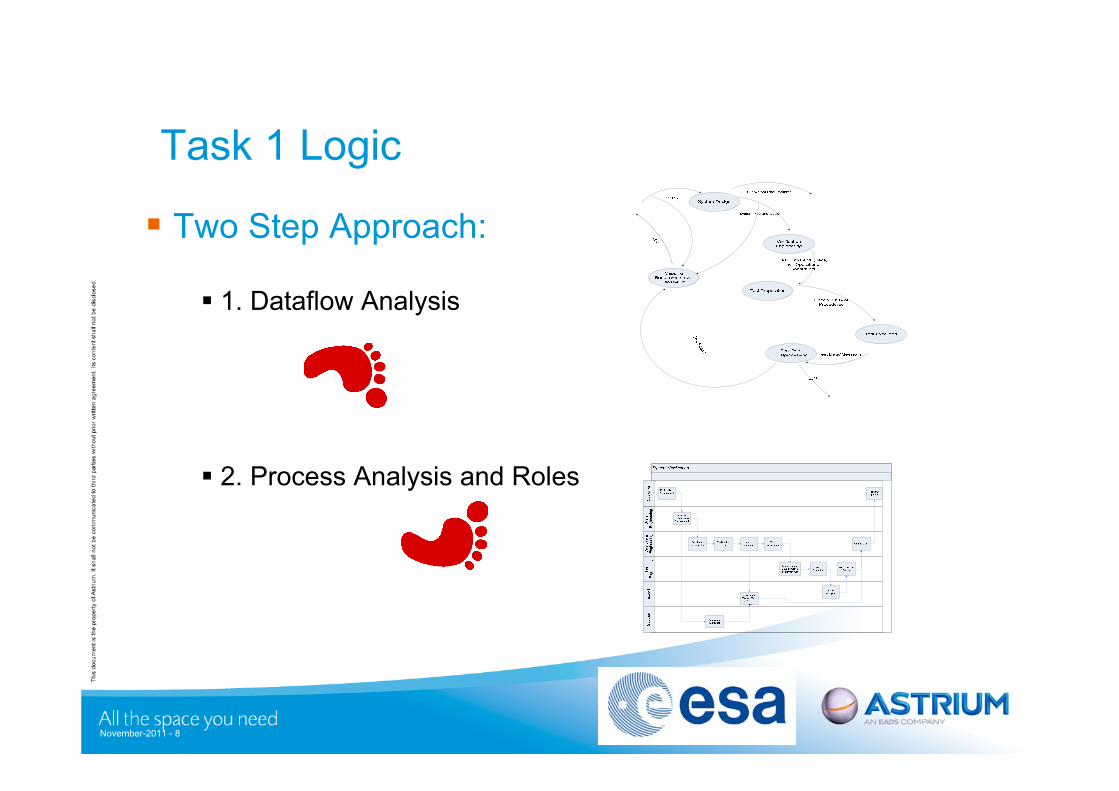
Task 1 Logic
Two Step Approach:
1. Dataflow Analysis
2. Process Analysis and Roles
November-2011 - 8
Task 1 Step 1 : Dataflow Analysis
November-2011 - 9
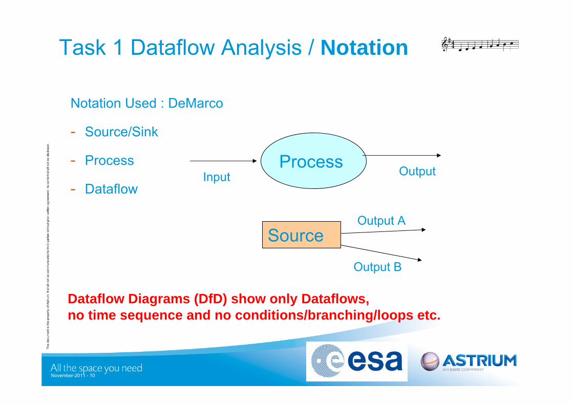
Task 1 Dataflow Analysis / Notation
Notation Used : DeMarco
- Source/Sink
- Process
- Dataflow
November-2011 - 10
Dataflow Diagrams (DfD) show only Dataflows, no time sequence and no conditions/branching/loops etc.
Process Input Output
SourceOutput A
Output B
Task 1 Dataflow Analysis /
Level 0 Context
Functional Verification
Customer
System RequirementsClose Out
System Engineering
Test EquipmentProduction
NCR Management
ChangeManagement
Produce Item UnderTest
Subsystem Requirements
VCD Inputs, Test Report
NCR and Related Information
Test Equipment Requirements
Baseline Change forTest Equipment
User Requirements
User Requirements
CR/Approval
Complete VCD
Non-Test Close-Outs
Test /Measurement Results
System Requirements andSpacecraft Design
RfW/RfD
Baseline Change for Item Under Test
RFW/RFD
Update/Delivery of Test Equipment
NCR & Related Information
NCR Close-Out Information
NCR
CR/Approval
CR/Approval
Subsystem VCD
Delivery/Update of Item Under Test
RfW/RfD
November-2011 - 11
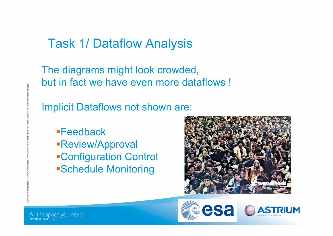
The diagrams might look crowded, but in fact we have even more dataflows !
Implicit Dataflows not shown are:
FeedbackReview/ApprovalConfiguration ControlSchedule Monitoring
Task 1/ Dataflow Analysis
November-2011 - 12
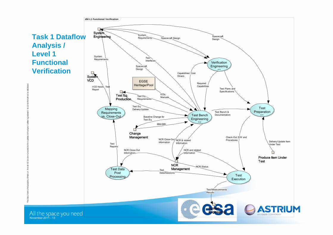
Task 1 Dataflow Analysis / Level 1 Functional Verification
dfd L1 Functional Verification
VerificationEngineering
TestPreparation
TestExecution
Test DataPost
Processing
MappingRequirementsvs. Close-Out Test Bench
Engineering
SystemVCDSystemVCD
SystemEngineeringSystemEngineering
EGSEHeritage/Pool
Test Eq.ProductionTest Eq.Production
SystemEngineeringSystemEngineering
NCRManagementNCRManagement
Produce Item UnderTestProduce Item UnderTest
ChangeManagementChangeManagement
TestInterfaces
RequiredCapabilities
Check-Out S/W andProcedures
TestData/Sessions
Test/MeasurementsResults
NCR and relatedInformation
TestReports
VCD Inputs, TestReport
Test Bench &Documentation
Capabilities/ CostDrivers
Test Eq.Requirements
Test Plans andSpecifications
Baseline Change forTest Eq.
RfW/RfD
SpacecraftDesign
SpacecraftDesign
SystemRequirements
SystemRequirements
Spacecraft Design
ICDs,Manuals
Test Eq.Delivery/Update
NCR Close-OutInformation
NCR Close-OutInformation
NCR Status
Delivery/Update ItemUnder Test
NCR & relatedInformation
November-2011 - 13
Task 1 Dataflow Analysis con ‘t
Wherever a infinity ∞ symbol is shown in the diagram is refined to lower level.
The following DfDs have been documented in Task 1 Report Context Diagram (External I/F) Verification Engineering Test Bench Engineering Test Preparation Configuration Control Configuration Control S/W Configuration Control H/W
November-2011 - 14
Task 1 Step 2 : Process Analysis and Roles
November-2011 - 15
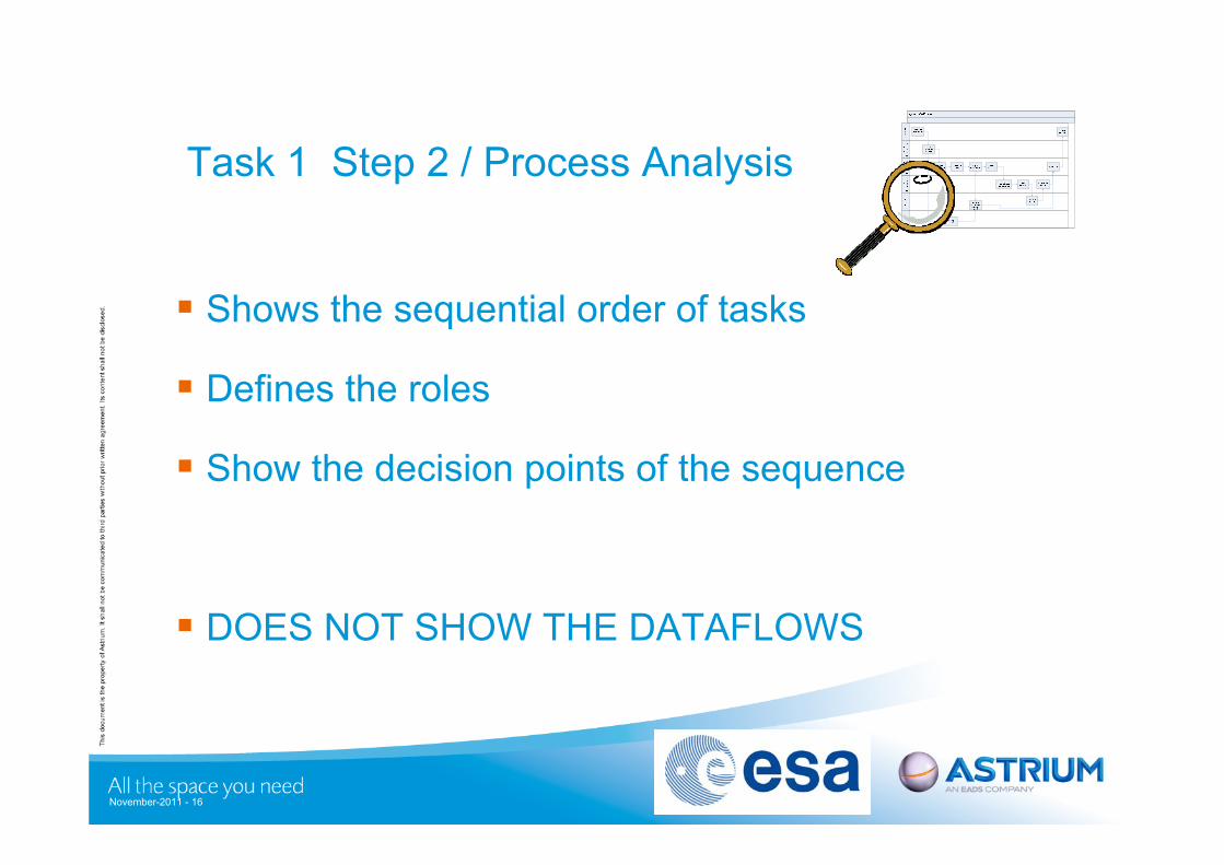
Task 1 Step 2 / Process Analysis
Shows the sequential order of tasks
Defines the roles
Show the decision points of the sequence
DOES NOT SHOW THE DATAFLOWS
November-2011 - 16
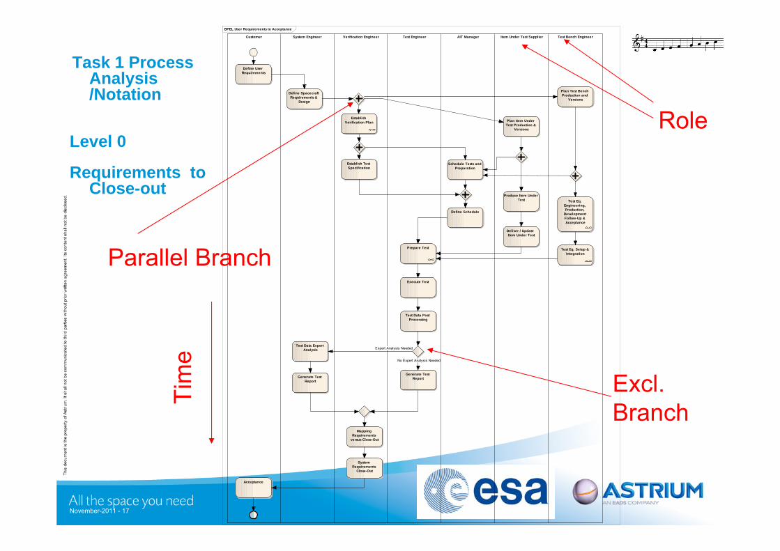
Task 1 ProcessAnalysis /Notation
Level 0
Requirements to Close-out
November-2011 - 17
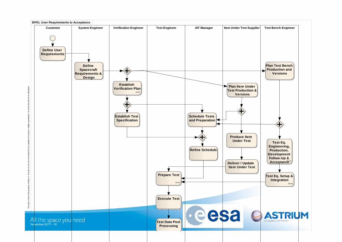
BPEL User Requirements to Acceptance
Customer System Engineer Verification Engineer Test Engineer AIT Manager Item Under Test Supplier Test Bench Engineer
Define User RequirementsDefine User
Requirements
Define Spacecraft Requirements &
Design
Define Spacecraft Requirements &
Design
Establish Verification Plan
Establish Verification Plan
Establish Test SpecificationEstablish Test Specification
Prepare TestPrepare Test
Execute TestExecute Test
Schedule Tests and Preparation
Schedule Tests and Preparation
Refine ScheduleRefine Schedule
Test Data Post Processing
Test Data Post Processing
Test Data Expert Analysis
Test Data Expert Analysis
Generate Test Report
Generate Test ReportGenerate Test
ReportGenerate Test
Report
Mapping Requirements
versus Close-Out
Mapping Requirements
versus Close-Out
System Requirements
Close-Out
System Requirements
Close-Out
AcceptanceAcceptance
Produce Item Under Test
Produce Item Under Test
Plan Item Under Test Production &
Versions
Plan Item Under Test Production &
Versions
Deliver / Update Item Under Test
Deliver / Update Item Under Test
Plan Test Bench Production and
Versions
Plan Test Bench Production and
Versions
Test Eq. Setup & Integration
Test Eq. Setup & Integration
Test Eq. Engineering, Production,
Development Follow-Up & Acceptance
Test Eq. Engineering, Production,
Development Follow-Up & Acceptance
Expert Analysis Needed
No Expert Analysis Needed
Tim
e
Role
Parallel Branch
Excl.Branch
November-2011 - 18
BPEL User Requirements to Acceptance
Customer System Engineer Verification Engineer Test Engineer AIT Manager Item Under Test Supplier Test Bench Engineer
Define User RequirementsDefine User
Requirements
Define Spacecraft
Requirements & Design
Define Spacecraft
Requirements & Design
Establish Verification Plan
Establish Verification Plan
Establish Test Specification
Establish Test Specification
Prepare TestPrepare Test
Execute TestExecute Test
Schedule Tests and PreparationSchedule Tests and Preparation
Refine ScheduleRefine Schedule
Test Data Post Processing
Test Data Post Processing
Produce Item Under Test
Produce Item Under Test
Plan Item Under Test Production &
Versions
Plan Item Under Test Production &
Versions
Deliver / Update Item Under Test
Deliver / Update Item Under Test
Plan Test Bench Production and
Versions
Plan Test Bench Production and
Versions
Test Eq. Setup & Integration
Test Eq. Setup & Integration
Test Eq. Engineering, Production,
Development Follow-Up & Acceptance
Test Eq. Engineering, Production,
Development Follow-Up & Acceptance
November-2011 - 19
Execute TestExecute Test
Test Data Post Processing
Test Data Post Processing
Test Data Expert Analysis
Test Data Expert Analysis
Generate Test Report
Generate Test ReportGenerate Test
ReportGenerate Test
Report
Mapping Requirements
versus Close-Out
Mapping Requirements
versus Close-Out
System Requirements
Close-Out
System Requirements
Close-OutAcceptanceAcceptance
Expert Analysis Needed
No Expert Analysis Needed
Task 1: Process Analysis The following BPNM diagrams have been generated:
User Requirements to Acceptance Establish Verification Plan Establish Verification Plan (Req. Driven) Test Eq. Engineering, Production, Development Follow-Up &
Acceptance Test Eq. Setup & Integration Test Preparation NCR Process RfW Generic: Baseline Change Process Generic: Concurrent Engineering Generic: Hierarchical Coordination Generic: Feedback (Formal Review) Generic: Feedback (Informal & Continuous)
November-2011 - 20
Task 2Develop a Conceptual Data Model of Functional Verification
November-2011 - 21
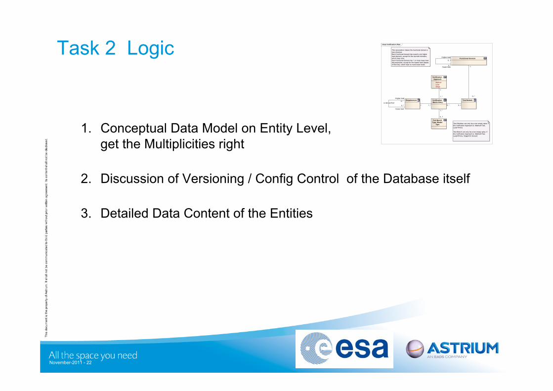
Task 2 Logic
1. Conceptual Data Model on Entity Level, get the Multiplicities right
2. Discussion of Versioning / Config Control of the Database itself
3. Detailed Data Content of the Entities
class Verification Plan
Requirement Test Module
Test Bench Type /Model
Type
Verification Approach
Method Level Stage
Test Modules can only be a non empty value, if the Verification Approach is: Method=Test, Level=Prime
Test Bench can only be a non empty value, if the Verification Approach is: Method=Test, Level=Prime, Stage=On Ground
This association makes the functional domain a tree structure. Each functional domain has exactly one higher level element, except for the top level domains, which have none.Each functional domain has 1 or more lower level decomposites, except for the lowest level (leaves of the tree), which have no more lower levels
Functional Domain
Verification Matrix Entry
1
1..*
1..*
0..1
0..* 0..11 1..*
+higher level
0..*is derived from
+lower level
0..*
1
0..*
+higher level
0..1
+lower level0..*
November-2011 - 22
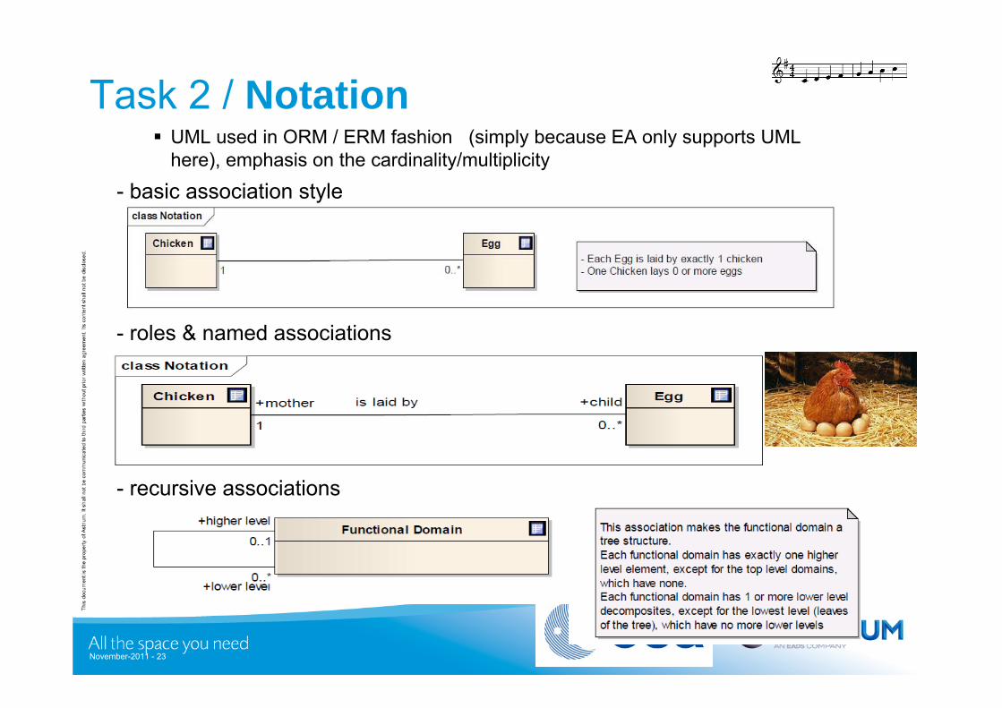
Task 2 / Notation UML used in ORM / ERM fashion (simply because EA only supports UML
here), emphasis on the cardinality/multiplicity
- roles & named associations
- basic association style
- recursive associations
November-2011 - 23
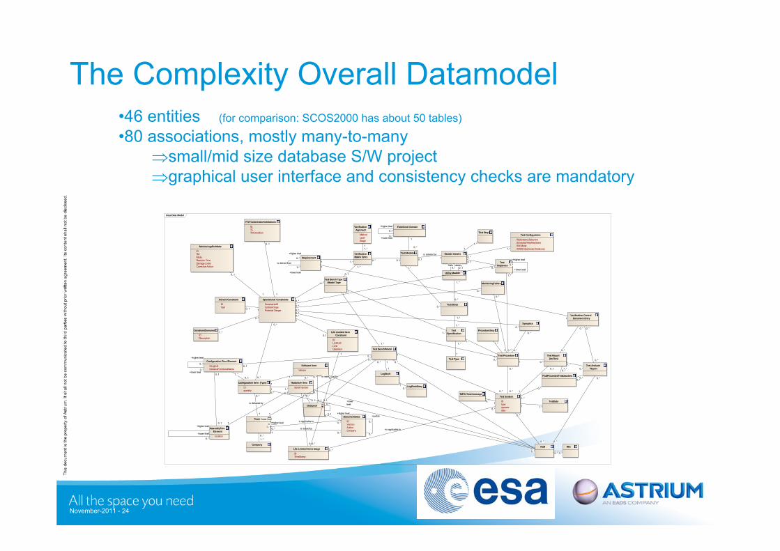
The Complexity Overall Datamodel
November-2011 - 24
class Data Model
Requirement
Test Module
Test Bench Type /Model Type
Verification Approach
Method Level Stage
Functional Domain
Module Details
Configuration Item (Type)
CI quantity
Software Item
Version
Test Bench/Model
Hardware Item
Serial Number
Datapack
Document/Data
ID Version Author Company
Team
Test Block
Utility Module
Test Specification
Test TypeTest Procedure Test Report
(As-Run)
Test Sequence
Company
Operational Constraints
ConstraintsID ContraintType Potential Danger
Test Session
ID type operator date
Life Limited Items Usage
ID TimeStamp
TMTC-Test-Coverage
MonitoringTables
Synoptics
Test Configuration
RedundancySelection Simulated-RealHardware SW-Mode AOCS-OpenLoop-CloseLoop
TestData
PreTransmissionValidations
ID TC TM-Condition
MonitoringsPerMode
ID TM Mode Reaction Time Damage Limits Corrective Action
GenericConstraint
ID Text
ConstraintDomains
ID Description
Test Analysis Report
NCR Rfw
PostProcessedTestDataSetsLogBook
LogBookEntry
Test Step
AssemblyTree Element
location
Configuration Tree Element
IsLogical InstanceFunctionalName
Verification Matrix Entry
Verification Control Document Entry
ProcedureStepLife Limited Item Constraint
ID LimitUnit Limit Operation
+is applicable to
0..*
+quotes
0..*
+higher level0..1
+lowerlevel0..*
0..*Calls0..* 0..1
details1
0..*
1..*
1..*
1..*
1..*
1..*
1
1..*
0..*
0..*
0..1
0..1
+higher level
0..1
+lower level0..*
1..*
0..*
+lower level
0..*
+higher level
0..*
1..*
0..*
0..*
is issued by1
0..*
is delivered by
1 1
is maintained by
0..*
0..1
1
0..*
0..*
1
1..*
0..1
0..*
0..*
0..*
0..*
0..*
0..*
0..*
1..*
1
1..*
0..*
+higher level
0..1
+lower level0..*
1
0..*
0..1
is detailed by1
0..* 0..1
1
1..*
1 1..*
0..*
0..1
0..*
0..1
0..1
0..1
0..*is applicable to
0..*
0..* 0..*
0..*
0..*
+higher level
0..*
is derived from
+lower level
0..*
0..*
0..*
0..*
1..*
1..*0..*
0..*0..*
0..*
0..*
1
1..*
1
1..*
0..11..*
+higher level
0..1+lower level
0..*
1..*
0..1
0..*1..*
0..*0..*
0..1
1
1
1
10..*
1
0..*
1 1..*
0..1
0..1
11..*
0..*
0..*
0..*
0..*
1..*
0..*
0..*
0..*
0..*
0..*
1
0..*
0..*
0..*
0..*
0..*
0..*
0..*
1 0..*1..*
0..*
0..*
0..*
0..*
0..*
10..*
1
0..*
1 1..*
+higher level
0..1
+lower level
0..*
0..1
1
0..1
1
10..1
0..*
0..*
1..*
0..1
1
1
0..*
0..*
•46 entities (for comparison: SCOS2000 has about 50 tables)
•80 associations, mostly many-to-manysmall/mid size database S/W projectgraphical user interface and consistency checks are mandatory
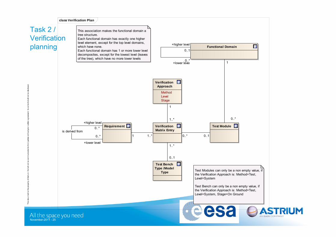
Task 2 /Verification planning
November-2011 - 25
class Verification Plan
Requirement Test Module
Test Bench Type /Model
Type
Verification Approach
Method Level Stage
Test Modules can only be a non empty value, if the Verification Approach is: Method=Test, Level=System
Test Bench can only be a non empty value, if the Verification Approach is: Method=Test, Level=System, Stage=On Ground
This association makes the functional domain a tree structure. Each functional domain has exactly one higher level element, except for the top level domains, which have none.Each functional domain has 1 or more lower level decomposites, except for the lowest level (leaves of the tree), which have no more lower levels
Functional Domain
Verification Matrix Entry
1
1..*
1..*
0..1
0..* 0..11 1..*
+higher level
0..*is derived from
+lower level
0..*
1
0..*
+higher level
0..1
+lower level0..*
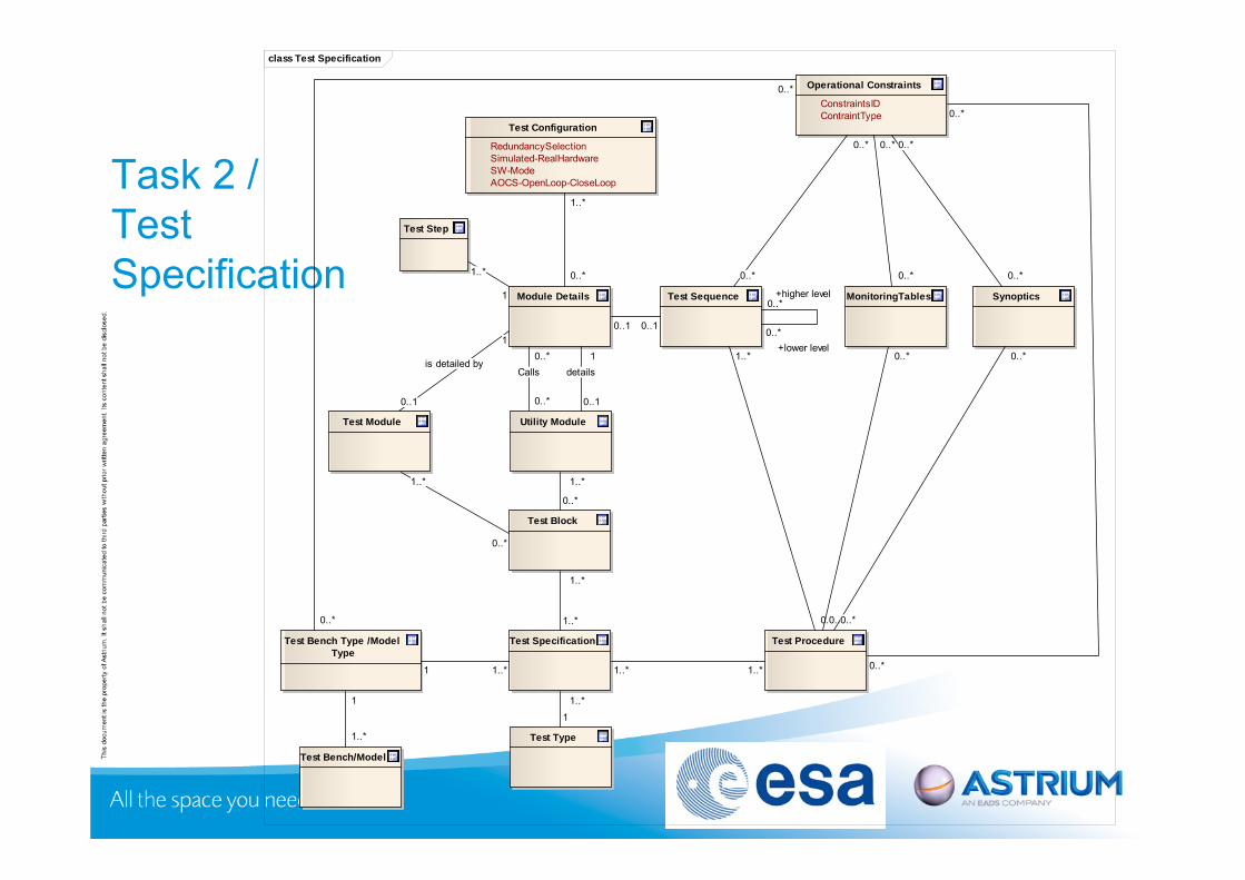
Task 2 /Test Specification
class Test Specification
Test Module
Test Bench Type /Model Type
Module Details
Test Bench/Model
Test Block
Utility Module
Test Specification
Test Type
Test Procedure
Test Sequence
Operational Constraints
ConstraintsID ContraintType
MonitoringTables Synoptics
Test Configuration
RedundancySelection Simulated-RealHardware SW-Mode AOCS-OpenLoop-CloseLoop
Test Step
1..*
0..*
0..*
1..*
1
1..*
0..*Calls
0..* 0..1
details1
0..*
1..*
1..*1..*
1..*
1..*
1
1..*
0..1
is detailed by
10..1 0..1
1
1..*
+lower level0..*
+higher level0..*
1..*
0..*
0..*
0..*
0..*
0..*
0..*
0..*
0..*
0..*
0..*
0..*
0..*
0..*
0..*
0..*1 1..*
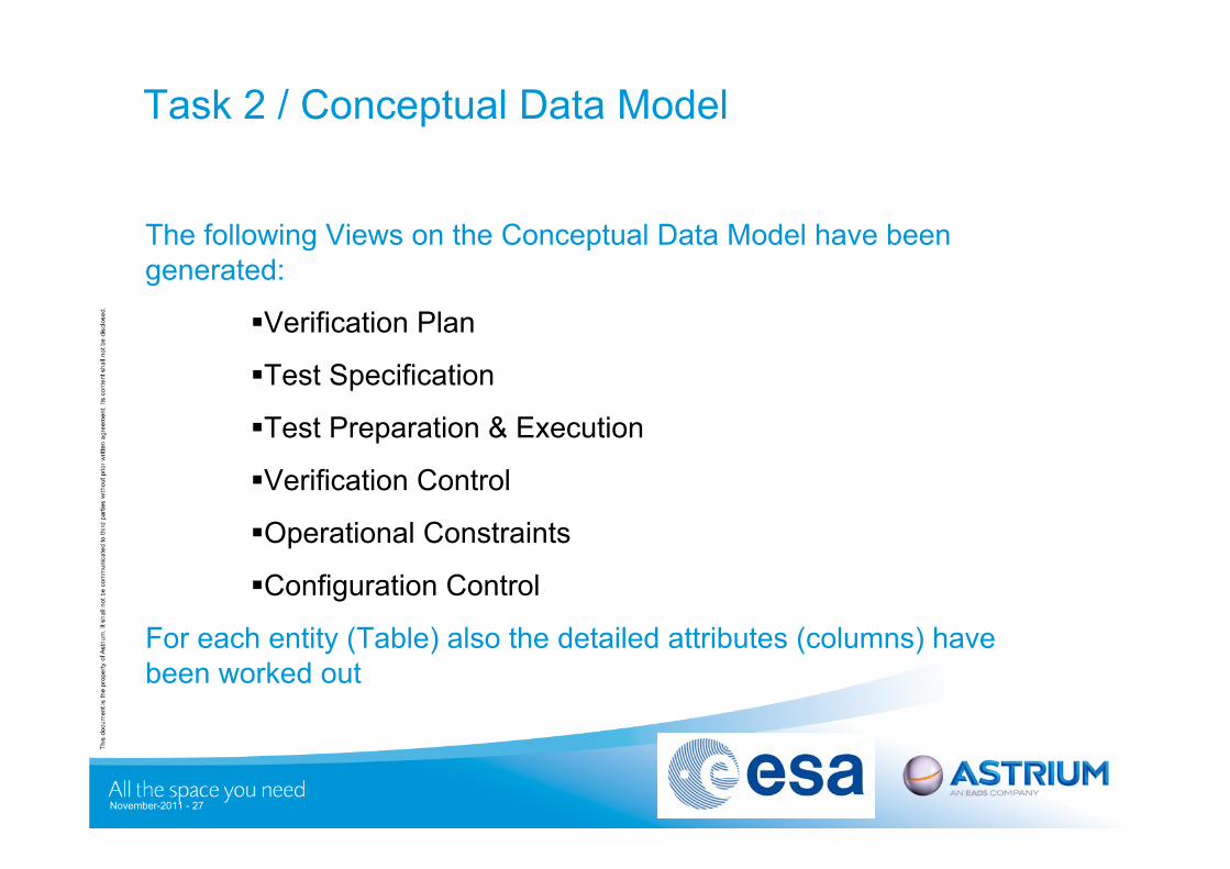
Task 2 / Conceptual Data Model
The following Views on the Conceptual Data Model have been generated:
Verification Plan
Test Specification
Test Preparation & Execution
Verification Control
Operational Constraints
Configuration Control
For each entity (Table) also the detailed attributes (columns) have been worked out
November-2011 - 27
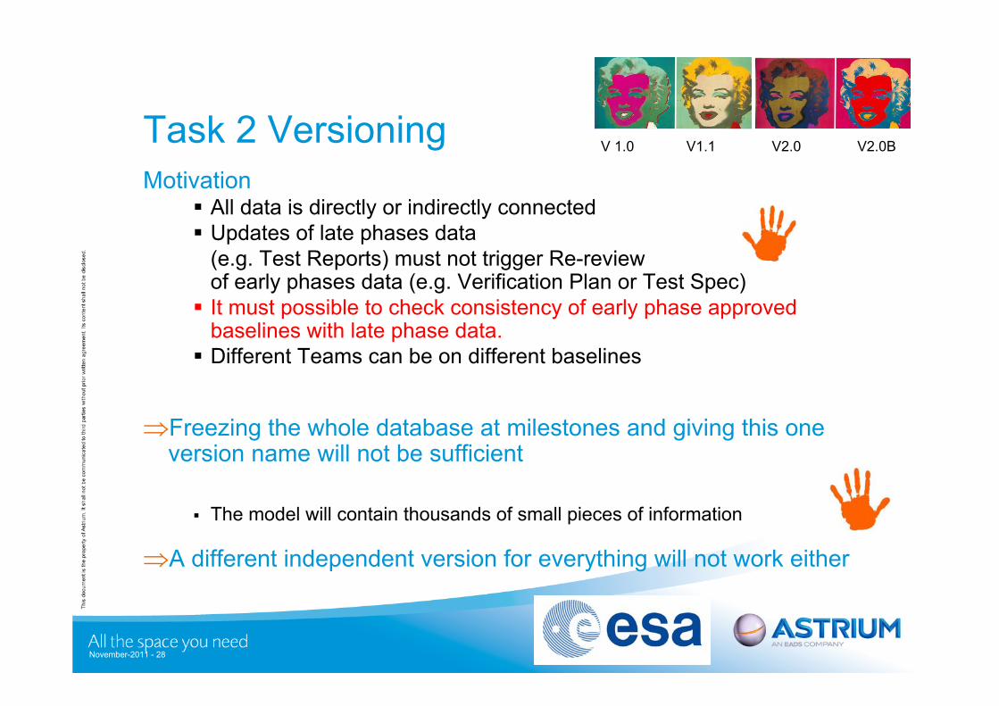
Task 2 VersioningMotivation
All data is directly or indirectly connected Updates of late phases data
(e.g. Test Reports) must not trigger Re-review of early phases data (e.g. Verification Plan or Test Spec) It must possible to check consistency of early phase approved
baselines with late phase data. Different Teams can be on different baselines
Freezing the whole database at milestones and giving this one version name will not be sufficient
The model will contain thousands of small pieces of information
A different independent version for everything will not work either
V 1.0 V1.1 V2.0 V2.0B
November-2011 - 28
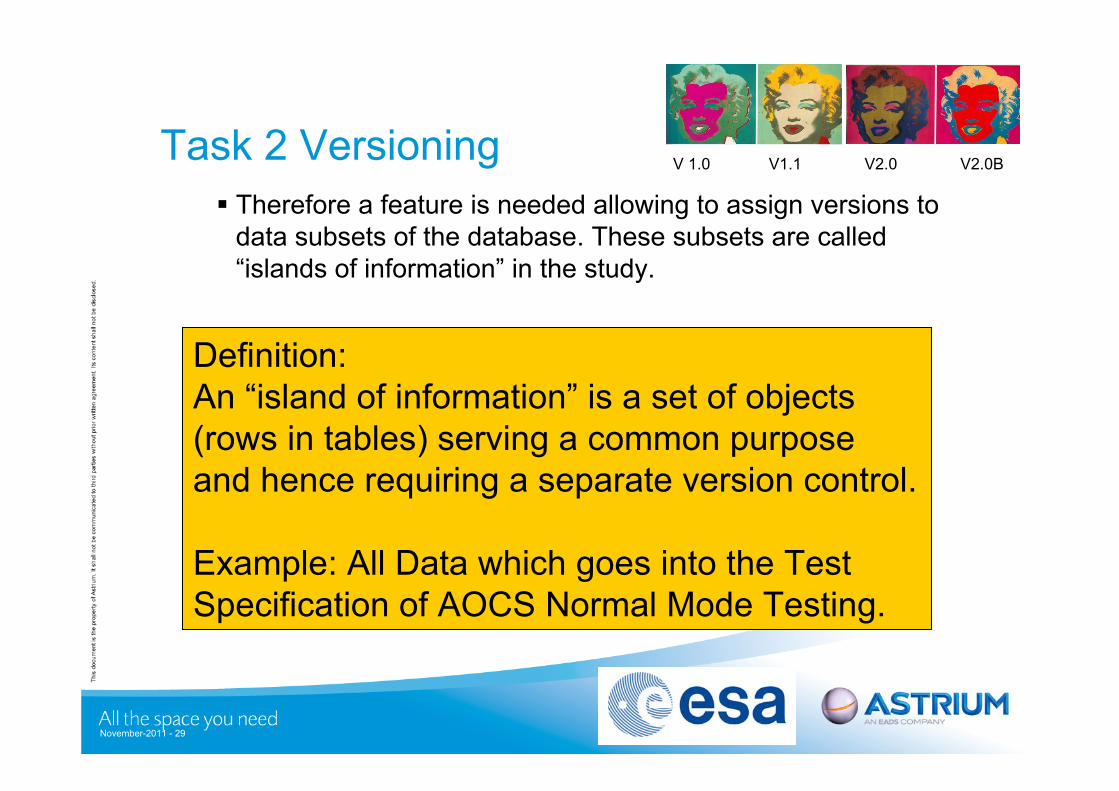
Task 2 Versioning Therefore a feature is needed allowing to assign versions to
data subsets of the database. These subsets are called “islands of information” in the study.
V 1.0 V1.1 V2.0 V2.0B
November-2011 - 29
Definition:An “island of information” is a set of objects (rows in tables) serving a common purpose and hence requiring a separate version control.
Example: All Data which goes into the Test Specification of AOCS Normal Mode Testing.
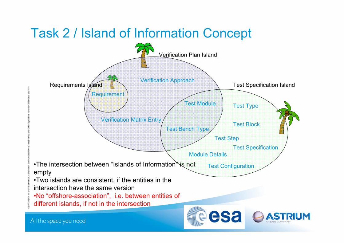
Task 2 / Island of Information Concept
•The intersection between “Islands of Information" is not empty•Two islands are consistent, if the entities in the intersection have the same version•No “offshore-association”, i.e. between entities of different islands, if not in the intersection
Test Specification IslandRequirement
Verification Approach
Test Bench TypeVerification Matrix Entry
Test Module Test Type
Test Block
Test SpecificationModule Details
Test Step
Test Configuration
Verification Plan Island
Requirements Island
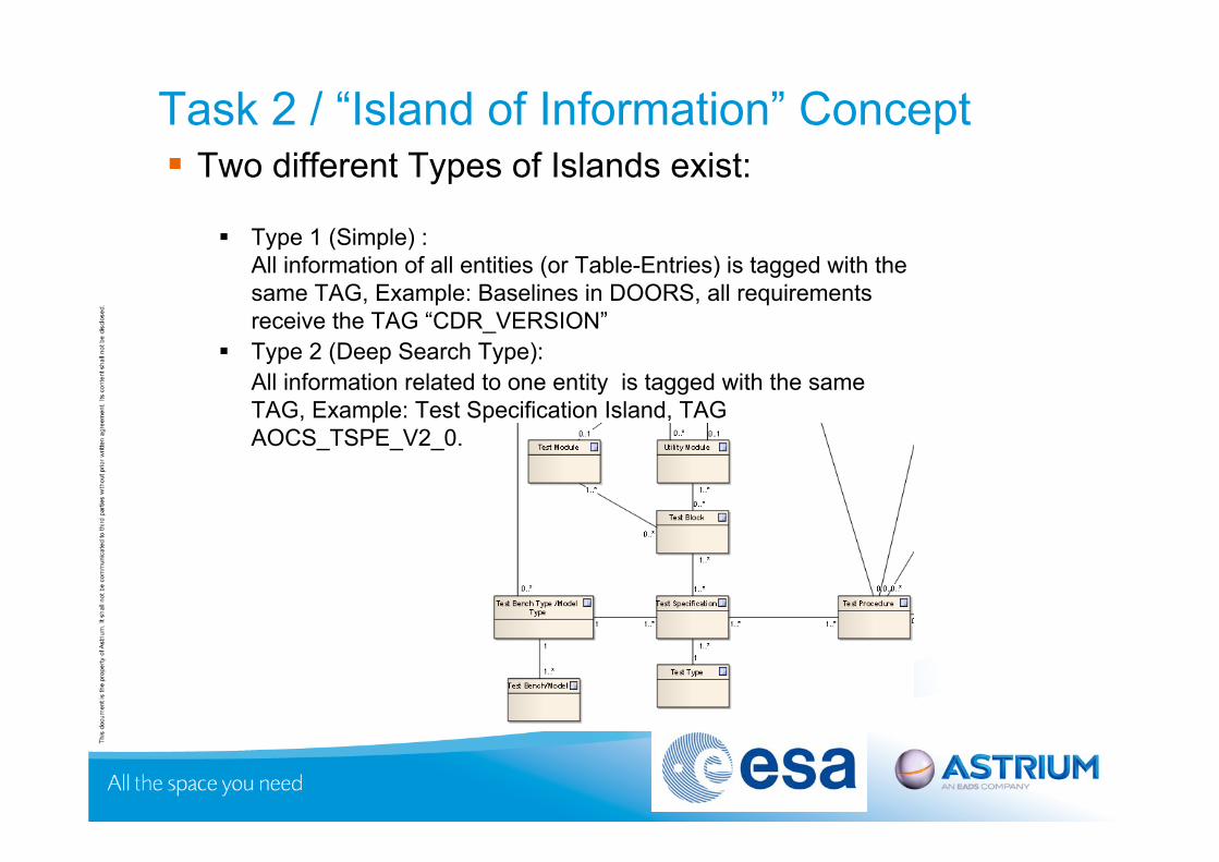
Task 2 / “Island of Information” Concept Two different Types of Islands exist:
Type 1 (Simple) :All information of all entities (or Table-Entries) is tagged with the same TAG, Example: Baselines in DOORS, all requirements receive the TAG “CDR_VERSION”
Type 2 (Deep Search Type):All information related to one entity is tagged with the same TAG, Example: Test Specification Island, TAG AOCS_TSPE_V2_0.

November-2011 - 32
Backup Slides
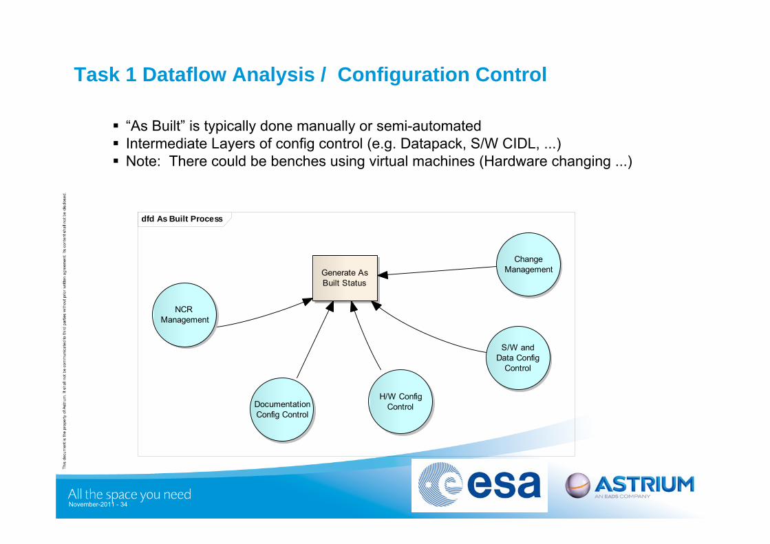
Task 1 Dataflow Analysis / Configuration Control
“As Built” is typically done manually or semi-automated Intermediate Layers of config control (e.g. Datapack, S/W CIDL, ...) Note: There could be benches using virtual machines (Hardware changing ...)
dfd As Built Process
DocumentationConfig Control
H/W ConfigControl
S/W andData Config
Control
Generate AsBuilt Status
NCR Management
ChangeManagement
November-2011 - 34
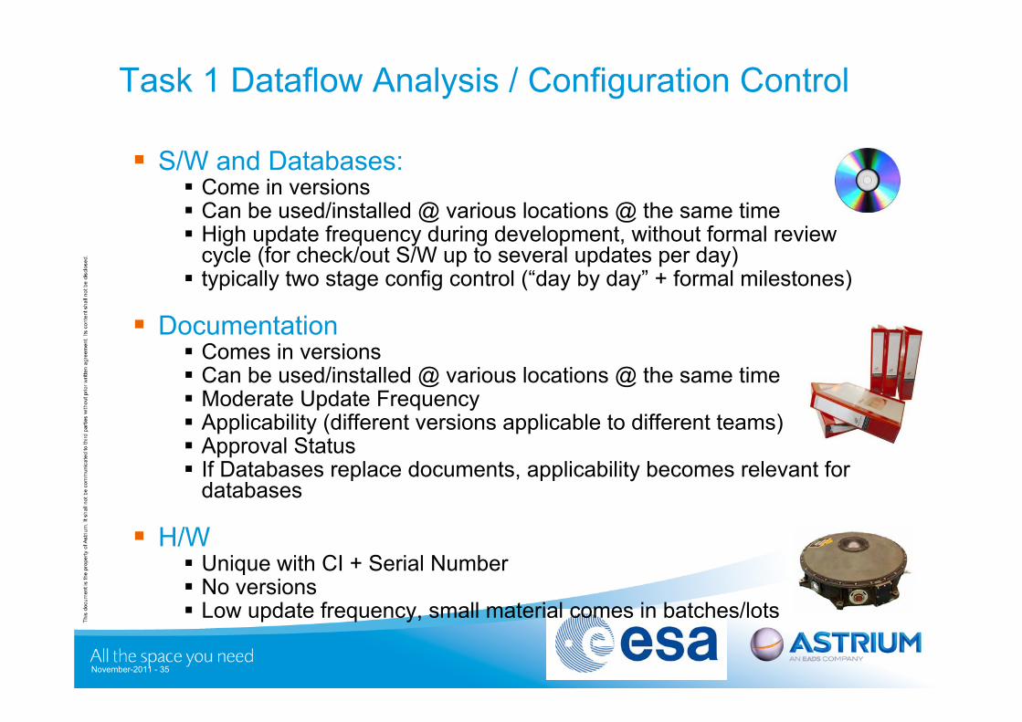
S/W and Databases: Come in versions Can be used/installed @ various locations @ the same time High update frequency during development, without formal review
cycle (for check/out S/W up to several updates per day) typically two stage config control (“day by day” + formal milestones)
Documentation Comes in versions Can be used/installed @ various locations @ the same time Moderate Update Frequency Applicability (different versions applicable to different teams) Approval Status If Databases replace documents, applicability becomes relevant for
databases
H/W Unique with CI + Serial Number No versions Low update frequency, small material comes in batches/lots
Task 1 Dataflow Analysis / Configuration Control
November-2011 - 35
NCR Management: like Documentation, but has Status is linked to configuration controlled items (S/W, H/W, Document)
Change Management like NCR management also linked to contract
Task 1 Dataflow Analysis / Configuration Control
November-2011 - 36
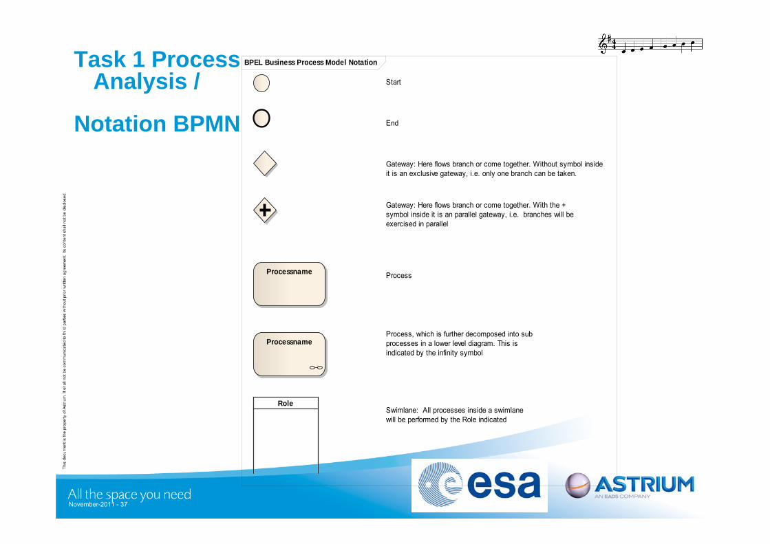
Task 1 Process Analysis /
Notation BPMN
BPEL Business Process Model Notation
Role
Start
End
Gateway: Here flows branch or come together. Without symbol inside it is an exclusive gateway, i.e. only one branch can be taken.
Gateway: Here flows branch or come together. With the + symbol inside it is an parallel gateway, i.e. branches will be exercised in parallel
ProcessnameProcessname Process
ProcessnameProcessnameProcess, which is further decomposed into sub processes in a lower level diagram. This is indicated by the infinity symbol
Swimlane: All processes inside a swimlane will be performed by the Role indicated
November-2011 - 37
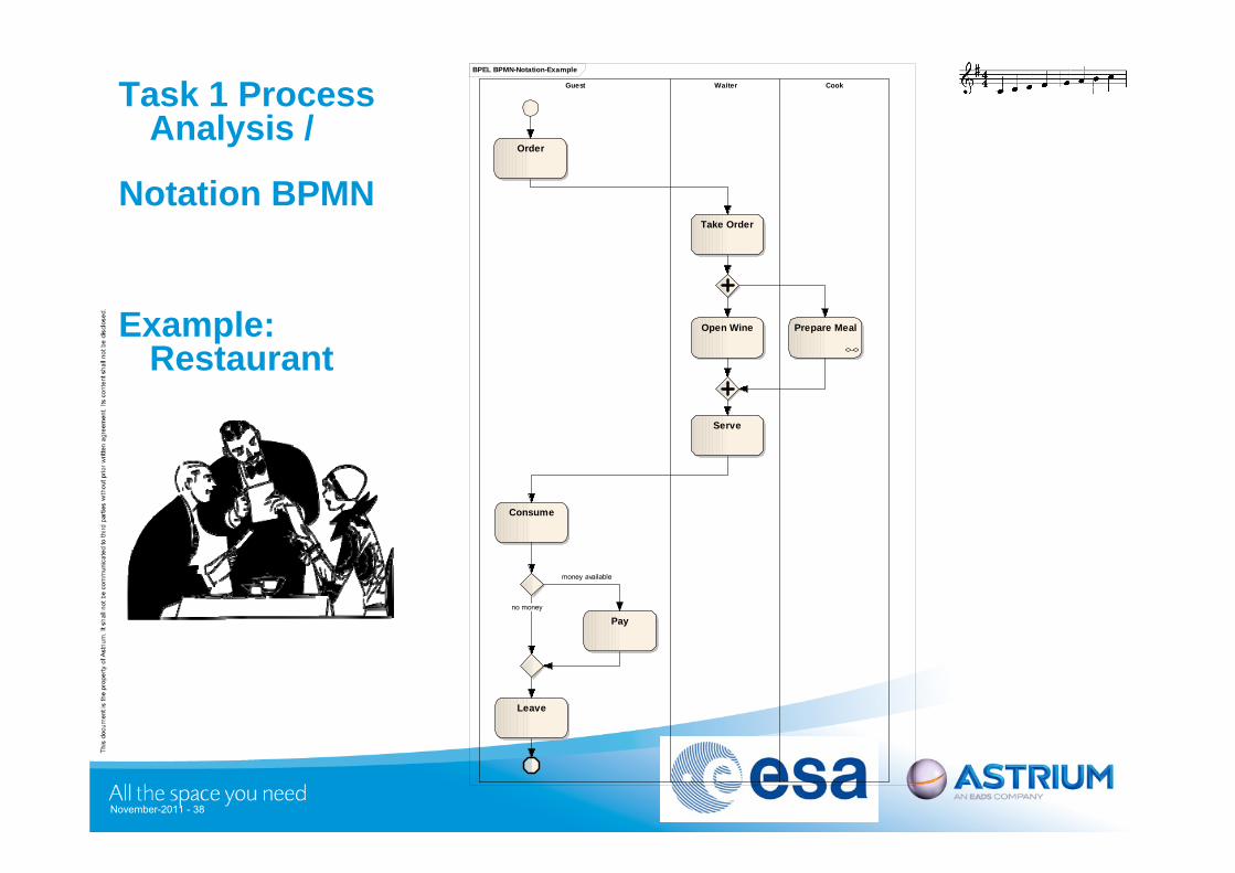
Task 1 Process Analysis /
Notation BPMN
Example: Restaurant
BPEL BPMN-Notation-Example
Guest Waiter Cook
OrderOrder
Prepare MealPrepare Meal
Take OrderTake Order
Open WineOpen Wine
ServeServe
ConsumeConsume
PayPay
LeaveLeave
no money
money available
November-2011 - 38
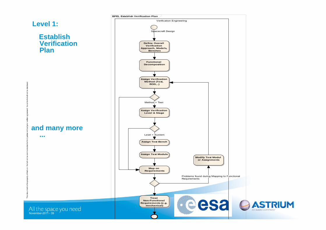
Level 1:
Establish Verification Plan
and many more ...
BPEL Establish Verification Plan
Verification Engineering
Functional Decomposition
Functional Decomposition
Spacecraft Design
Define Overall Verification
Approach, Models, Benches
Define Overall Verification
Approach, Models, Benches
Assign Verification Method (Test,
ROD,..)
Assign Verification Method (Test,
ROD,..)
Assign Verification Level & Stage
Assign Verification Level & Stage
Assign Test BenchAssign Test Bench
Assign Test ModuleAssign Test Module
Map on Requirements
Map on Requirements
Modify Test Modul or Assignments
Modify Test Modul or Assignments
Treat Non-Functional
Requirements (e.g. mechanical)
Treat Non-Functional
Requirements (e.g. mechanical)
Method = Test
Level = System
Problems found during Mapping to FunctionalRequirements
November-2011 - 39
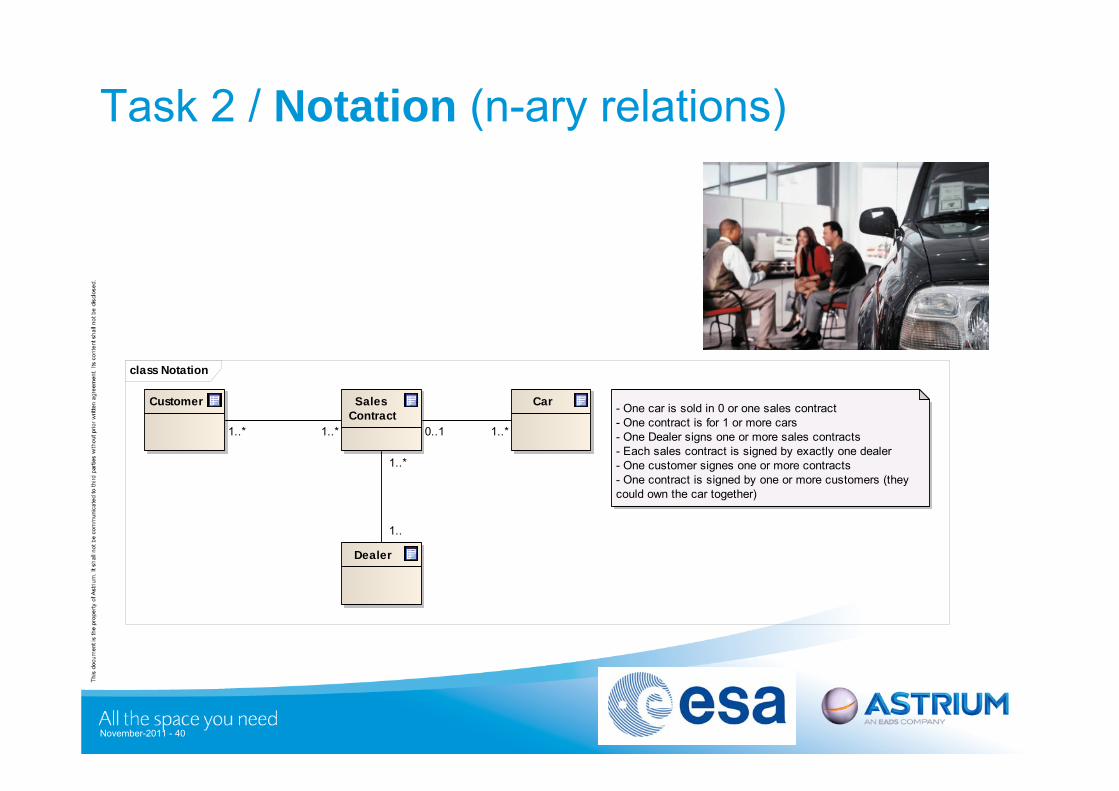
Task 2 / Notation (n-ary relations)
class Notation
Customer Car
Dealer
- One car is sold in 0 or one sales contract- One contract is for 1 or more cars- One Dealer signs one or more sales contracts- Each sales contract is signed by exactly one dealer- One customer signes one or more contracts- One contract is signed by one or more customers (they could own the car together)
Sales Contract
1..*
1..
0..1 1..*1..* 1..*
November-2011 - 40
Task 2 / “Island of Information” URD a) Whenever a data entry in one of the data entities is saved and released for used by others
the entry shall receive a new version number (e.g. a "Module Detail" Entity is updated, is gets a new version. Test engineers need to update the corresponding test sequence)
b) For user ergonomics it needs also to be possible to release all entries of an entity. Only the modified ones shall be incremented wrt. version in this case (E.g. release all "module details", all versions of "module details" modified since the last release are incremented).
b) Beside from the versions related to single data entries, it needs to be possible to tag "islands of information" with a common version name. (E.g. all data related to AOCS ISST test specification is tagged AOCS_ISST_SPEC_2B). The natural "islands of information" follow the deliverables of the ECSS (verification plan, test specification, test procedure, …).
c) The intersection between "island of information" is not empty. E.g. a Test Module is part of the "verification planning island" and the "test specification island". Example: the Test Module "GPS Switch Over" has the version 5.27, it also has the tag VERIFICATION_PLAN_5A and the tag AOCS_ISST_SPEC_2B.
d) Versioning needs to support the capability to check, if given versions of two different "islands of information" are consistent. This is done by checking, if all data being common to the different "islands of information" is of the same version. Example: Check if AOCS_ISST_SPEC_2B is consistent to VERIFICATIO_PLAN_5A (Example for the outcome of such a consistency check could be: Everything O.K., but the Test Bench proposed by the VERIFICATION_PLAN_5A for the Test Module "GPS Switch Over" is EFM, while the AOCS_ISST_2B defines SVF as the Test Bench to be used.)
e) Last not least versioning also needs to support that all data stored the data model is assigned a common tag (e.g. STATUS_SATELLITE_CDR, or BACKUP_BEFORE_CHRISTMAS).
November-2011 - 41