Embed Size (px)
Citation preview
Contents
Hazardous voltage will cause death or serious injury. Turn off andlock out all power supplying this device before working on this device.Replace all covers before power supplying this device is turned on.
Installation & Maintenace must be carried out by qualified personnel.
NOTICE
DANGEREN !
Required tools
2.5 mm5.0 mm
8 mm10 mm13 mm
0.5 x 3 mm PZ 4
Assembly
0.5 x 3 mm
Ø5.5A
25
Center ofShaft
IEC 60947-1IEC 60947-3
2P: 2x3P: 3x4P: 4x
1x
2x2P: 4x3P: 6x4P: 8x
1x
For 3KL83K.82..-5M8 x 20
3K.821..M6 x 143K.823..M8 x 14
Permissible mounting position
Drilling Plan for mounting plate
L1V30606645002-01 | 01
POLE
8UC62..
A
3KL82...-.. (100A-160A)3KA82...-.. (100A-160A)
Mounting Details:
SENTRON SUPERSWITCHSwitch Disconnector Fuse - Size 2
2P/3P/4P : M5 x 20 (4x)Torque 1.5....2.1 Nm(Not in scope of supply)
Last Update: June 2020
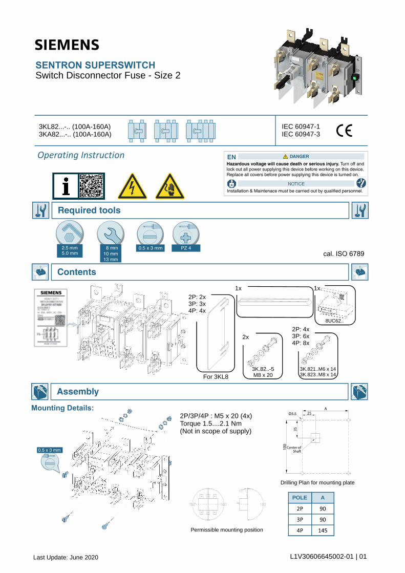
Connection
Assembly
10 mm/13
2.5 mm
1
10 mm
L1V30606645002-01 | 02
Provision for Fuse monitoring
2
2
10 mm/13
3KL821.../3KA821....3KL822.../3KA822....Max. Lug Size.... 70mmM6 x 20, Torque 6 Nm to 7.5 Nm
3KL823....../3KA823....Max. Lug Size.... 95 mmM8 x 20, Torque 7 Nm to 10 NmM6 x 20, Torque 6 Nm to 7.5 Nm
Installation of Shaft

Assembly
Assembly
1 2 3 4 5 6
10 mm2.5 mm
PZ 4
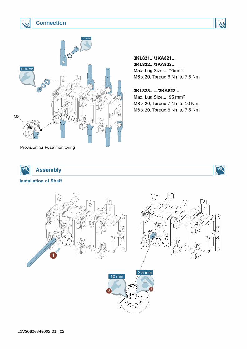
183...240
P4X11.51.1....1.3Nm
5.5 129 1
1 2 3 4 51 2 3 4
DIN: 3KX81530AEBS : 3KX82330JE
Adjust Depth of Drive as per dimensional plan
L1V30606645002-01 | 03
8UC Coupler depth adjustmentUse Depth Setting Templet - 8UC6046-2
Panel Door1.5....4Thk
Coupler
8UC 3K
2P : Phase Barrier in position 2 & 3 are essential
3P : Phase Barrier in position 2, 3 & 4 are essential
4P : Phase Barrier in position 2, 3, 4 & 5 are essential
Mounting Details for Front Drive8UC6214-1BB00
Phase Barrier:
Notice : Possible damage if adjusted beyond limits
EN WARNING!

Assembly
0,5 x 3 mm
1 mm3
1 mm3
2P : 3KX82310AF3P : 3KX82310AE4P : 3KX82310AG
M8 X 20Torque 7.0 Nm. To 8.5 Nm.
L1V30606645002-01 | 04
Terminal cover
Installation of BS Fuse
Assembly
Assembly
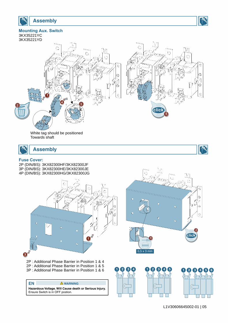
Hazardous Voltage. Will Cause death or Serious Injury.Ensure Switch is in OFF postion.
EN WARNING!
0,5 x 3 mm
1 2 3 4 5 61 2 3 4 51 2 3 4
L1V30606645002-01 | 05
2P : Additional Phase Barrier in Position 1 & 42P : Additional Phase Barrier in Position 1 & 53P : Additional Phase Barrier in Position 1 & 6
2P (DIN/BS): 3KX82300HF/3KX82300JF3P (DIN/BS): 3KX82300HE/3KX82300JE4P (DIN/BS): 3KX82300HG/3KX82300JG
White tag should be positionedTowards shaft
Mounting Aux. Switch
Fuse Cover:
3KX35221YC3KX35221YD

Informationi i
Informationi i
L1V30606645002-01 | 06
Type B C D E F G H J K L3KL/3KA 821/822 15 45 6.5 108 131 12 2 15 74 90
20 50 9 91 106 15 3 17 85 100
30 30240
TERMINAL
Dimension Details for SDF in Enclosure
Overall Dimensional details3P(3KL8)/3P+N
3KL8/3KA8 : 2P 3KL8/3KA8 : 4P
For other Dimensions refer 3P/3P+N For other Dimensions refer 3P/3P+N
3KL/3KA 823