Embed Size (px)
Citation preview

Cyberex® SuperSwitch®
3 technology200–4000A digital static transfer switch
Product brochure

2 Product brochure | Cyberex® SuperSwitch®3 digital static transfer switch
SuperSwitch3 redefines reliability
Forty years ago, Cyberex revolutionized power distribution with its invention of the Static Transfer Switch. Since then, Cyberex has installed more units than any other manufacturer. It is from this experience and our customers’ requirements that the SuperSwitch3 has evolved.
Designed with a ‘true’ fault-tolerant architecture, SuperSwitch3 ensures there is truly no single point of failure through the use of our patented transfer algorithm and robust electrical components. With an increased MTBDE to an estimated 1.5 million hours, SuperSwitch3 reliability is unmatched. SuperSwitch3 redefines power reliability with its exceptional design, serviceability and user-interface.
– Fault-tolerant architecture eliminates single point of failure
– Patented SuperSwitch algorithm delivers unmatched transfer characteristics
– Dynamic inrush restraint protects system by minimizing downstream magnetizing currents
– Three tiered user-defined thresholds for power quality management
– Software-guided breaker operation eliminates human error
– Graphical user-interface and mimic panel for local system monitoring and configuration
– Remote access capability for system, event and alarm monitoring
– Flexible access for ease of cabling, operation and maintenance
– Alarms, metering and diagnostics
– Detailed monitoring, reporting capability
– Advanced communications allow access at any time from any location
– Unique modular design reduces open-door time to 15 minutes for standard servicing
– Ultra-dense footprint reduces demand on valuable dataroom real estate
– Reduced number of internal components maximizes reliability
Alternate Source
Preferred Source
RPP PDUCyberex SS3
Server Rack
SuperSwitch3 provides added reliability to any architecture
Breakthrough technology
SuperSwitch®
3 technology200–1000A

Cyberex® SuperSwitch®3 digital static transfer switch | Product brochure 3
EVENTS MENU
LOGIN
HELP
ACK
CANCEL
OUTPUT
LOADA
S1BYPASS
S2BYPASS
S2INPUT
S1INPUT
IN SYNC
ALARM
SOURCE 2AVAILABLE
SOURCE 1AVAILABLE
LOADB
Dynamic inrush for applications with downstream transformers
Based on loading and power system parameters, SuperSwitch3 can dynamically modify its standard transfer switching algorithm. This technology limits the load inrush current in situations where the switch must make an immediate transfer to preserve load power quality. This breakthrough technology not only restricts the stress on fuses and breakers in the power distribution train, but also minimizes the chance of load interruption. Ultimately, this capability provides the maximum possible power quality of the voltage output for mission critical applications.
Expert power management
With ever-increasing power requirements and the necessity to ensure uptime, SuperSwitch3 provides exceptional power management.
Waveform capture
SuperSwitch3 is available with waveform capture. The Cyberex waveform capture feature uses digital signal processors and high speed analog to digital converters to simultaneously sample both source voltages and currents. The waveform data is collected in 0.1 millisecond intervals as 12 bit samples to provide an extremely high level of detail.
The SuperSwitch3 is capable of storing 25 waveform capture events for both transfer and non-transfer events. Each measurement contains a total of 6 cycles; 3 cycles prior to the event and 3 cycles after the event.
The waveform can be sent via email and imported into an Excel spreadsheet for additional viewing and analysis.
Software-guided breaker operation and bypass
Easy to follow command and indicator lights eliminate the causes of human error.
Data and alarm management
With over 100 warnings/alarms types, 2500 events can be stored or downloaded for analysis.
Remote access
Compatibility with building management systems provides access from any location at any time.
VbcVca
Vab
-10 -5 0 5
680
0
-680
Command View Event Options
Output
Voltage Current
Cancel
Command View Event Options
factory
ON SOURCE 1
1: 2:
Latest Events
Nov 20 2003 4: 17 am 480 V 400 A 60 Hz
Source 1
Phase A-B: 486 V (101%) A-N: 280 VPhase B-C: 492 V (102%) B-N: 285 VPhase C-A: 485 V (102%) C-N: 280 V
Source 2
Phase A-B: 471 V (98%) A-N: 272 VPhase B-C: 472 V (98%) B-N: 272 VPhase C-A: 479 V (99%) C-N: 277 V
Voltage
Phase A-B: 469 V
Phase B-C: 471 V
Phase C-A: 477 V
Output
Command View Event Options
lab2
ON SOURCE 2
1: 2:
Preferred
--> 43:15 A* Breaker S1 INPUT is now OPEN15:43:15 A* Source 1 is unavailable (red PQ)15:43:14 I +Transfer due to Active PQ Red successfully completed
Latest Events
Nov 20 2003 4: 17 am 480 V 400 A 60 Hz
BreakersMessage
To prevent transferthe unit will open the source 2 Input breakerin 5 seconds.
1
CancelUndo
Command View Event Options
factory
ON SOURCE 1
1: 2:
Latest Events
Nov 20 2003 4: 17 am 480 V 400 A 60 Hz
Transfer Configuration
OK Cancel
Transfer
Preferred Source
TransferAutomatic TransferDynamic Transfer
Source 1 Source 2
User-friendly control and mimic panel on all SS3 systems provide quick system configuration, power monitoring and response to alarms

4 Product brochure | Cyberex® SuperSwitch®3 digital static transfer switch
Power stage assembly
Fully rated hockey puck SCRs are employed to prevent system damage after load faults. The superior cooling design of the assembly enables higher current applications. Infrared scans are easily accomplished without removal of assembly.
Small-footprint chassis
As much as 30% smaller than comparable industry models, the ultra-dense design maximizes floor space. Ease of installation and flexibility are ensured by flexible access from either the front, side or rear. Power connections are made from either the top or bottom.
Main logic board
Integral design provides advanced diagnostics and management of three-tiered power quality. Separate boards are used for each source, while independent drive circuits, with high fault isolation, are used for each phase. Fiber optic communications between the Gate Drive Board improves noise immunity and fault isolation.
Reliability through design excellence
SuperSwitch3 provides maximum reliability through its innovative design. The modular components, from the power stage to the redundant bus architecture, have been engineered to unprecedented standards. With the fewest numbers, yet most reliable components, SuperSwitch3 ensures the highest level of functionality and minimum open-door time.
Power wiring and bus
Connections and maintenance are made easier by staggered phase connections and ample gutter space. 100% of connections are torqued ensuring maximum reliability.
Innovative arrangement provides optional access for operation, installation and maintenance
SuperSwitch®3 technologyRedefining reliability
Cyberex® SuperSwitch®3 digital static transfer switch | Product brochure 5
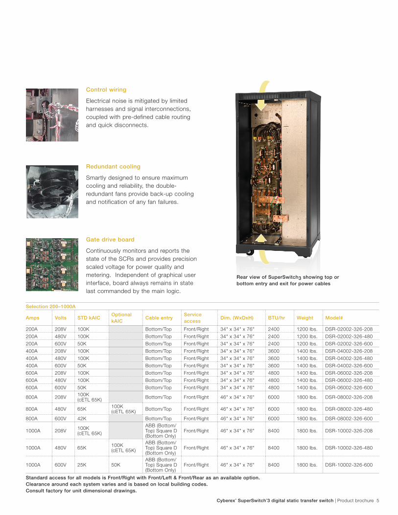
Redundant cooling
Smartly designed to ensure maximum cooling and reliability, the double-redundant fans provide back-up cooling and notification of any fan failures.
Gate drive board
Continuously monitors and reports the state of the SCRs and provides precision scaled voltage for power quality and metering. Independent of graphical user interface, board always remains in state last commanded by the main logic.
Control wiring
Electrical noise is mitigated by limited harnesses and signal interconnections, coupled with pre-defined cable routing and quick disconnects.
Standard access for all models is Front/Right with Front/Left & Front/Rear as an available option. Clearance around each system varies and is based on local building codes. Consult factory for unit dimensional drawings.
Selection 200–1000A
Amps Volts STD kAICOptional kAIC
Cable entry Service access
Dim. (WxDxH) BTU/hr Weight Model#
200A 208V 100K Bottom/Top Front/Right 34" x 34" x 76" 2400 1200 lbs. DSR-02002-326-208
200A 480V 100K Bottom/Top Front/Right 34" x 34" x 76" 2400 1200 lbs. DSR-02002-326-480
200A 600V 50K Bottom/Top Front/Right 34" x 34" x 76" 2400 1200 lbs. DSR-02002-326-600
400A 208V 100K Bottom/Top Front/Right 34" x 34" x 76" 3600 1400 lbs. DSR-04002-326-208
400A 480V 100K Bottom/Top Front/Right 34" x 34" x 76" 3600 1400 lbs. DSR-04002-326-480
400A 600V 50K Bottom/Top Front/Right 34" x 34" x 76" 3600 1400 lbs. DSR-04002-326-600
600A 208V 100K Bottom/Top Front/Right 34" x 34" x 76" 4800 1400 lbs. DSR-06002-326-208
600A 480V 100K Bottom/Top Front/Right 34" x 34" x 76" 4800 1400 lbs. DSR-06002-326-480
600A 600V 50K Bottom/Top Front/Right 34" x 34" x 76" 4800 1400 lbs. DSR-06002-326-600
800A 208V 100K (cETL 65K) Bottom/Top Front/Right 46" x 34" x 76" 6000 1800 lbs. DSR-08002-326-208
800A 480V 65K 100K (cETL 65K) Bottom/Top Front/Right 46" x 34" x 76" 6000 1800 lbs. DSR-08002-326-480
800A 600V 42K Bottom/Top Front/Right 46" x 34" x 76" 6000 1800 lbs. DSR-08002-326-600
1000A 208V 100K (cETL 65K)
ABB (Bottom/Top) Square D (Bottom Only)
Front/Right 46" x 34" x 76" 8400 1800 lbs. DSR-10002-326-208
1000A 480V 65K 100K (cETL 65K)
ABB (Bottom/Top) Square D (Bottom Only)
Front/Right 46" x 34" x 76" 8400 1800 lbs. DSR-10002-326-480
1000A 600V 25K 50KABB (Bottom/Top) Square D (Bottom Only)
Front/Right 46" x 34" x 76" 8400 1800 lbs. DSR-10002-326-600
Rear view of SuperSwitch3 showing top or bottom entry and exit for power cables

6 Product brochure | Cyberex® SuperSwitch®3 digital static transfer switch
Front view of SuperSwitch 4000A showing system modularity
Rear view of SuperSwitch 4000A showing system modularity
SuperSwitch3 1200–4000A
Designed with a true fault tolerant architecture, SuperSwitch ensures continuous protection in the event of a power disturbance. Rated from 1200 to 4000 Amps, SuperSwitch is a key design element for large, mission critical commercial and industrial applications.
The higher ampacity allows the SuperSwitch to deploy as a solution either at the utility entrance or closer to the mission critical loads in the data center. Whether the sources are UPS systems, utilities or generators, SuperSwitch delivers the most cost-effective protection.
Graphical user-interface
User-friendly software and ‘rapid response’ mouse allow for quick system configuration, power monitoring and response to alarms. Independent mimic panel provides redundancy to LCD data.
Printed circuit boards
Designed to eliminate a single point of failure, control boards are easily accessible for concurrent maintenance and removed without load disruption. LED indication quickly provides comprehensive self-diagnosis status.
Molded case switches
Provide maximum interruption for fault currents and eliminate nuisance trips. Plug-in style components designed for easy and quick exchange.
Power supply
With each supply capable of supporting all control power, the triple-redundant design ensures reliability. In the event of a fault, multiple alarms are activated.
0' 1' 2' 3' 4' 5' 6' 7' 8' 9' 10' 11' 12' 13' 14' 15' 16'
SuperSwitch®
3 technology1200–4000A

Cyberex® SuperSwitch®3 digital static transfer switch | Product brochure 7
Standard access for 1200A models is front/right with front/left & front/rear as an available option. Clearance around each system varies and is based on local building codes. Consult factory for unit dimensional drawings.
Specifications 200–4000AComponents
SCR Fully-rated, hockey-puck type
Mimic panel LED current flow
LCD Graphical, backlit (std.)
Color display (std.)
Fans Dual redundant
Power supplies Triple redundant
Internal bus Dual redundant
Surge protection 80kA (200–1200A)
200kA (1600–4000A)
Communications and software
Password protection Defined user tiers
Remote access RS232, RS485 and web-based
Event types Information, warnings and alarms
Alarm Audible alarm capability with notifications
(or email to pager)
Software upgrades Remote/local downloadable
Emergency power off Remote (std.), local (opt.)
Relay contacts 5 (std.)
Power and event management
Metering 1 kVA, kW, Ipeak, phase, current, voltage,
frequency
Metering 2 Power factor, kVA demand,
harmonic analyzer
Event alarm log 2500 events
Electrical characteristics
Voltage/frequency 208V/380V/400V/415V/480V/600V
50Hz/60Hz
Current rating 200A/400A/600A/800A/1000A/
1200A/1600A/2000A/3000A/4000A
Short-circuit withstand 25–100kA (voltage dependent)
Overload capability 125% (30 min.) 150% (1 min.)
1000% (3 cycles)
Circuit breakers Non-automatic or automatic
Operational characteristics
Controls Full digital
Type I 3000–4000A Fused protected
Type II 200–2000A Fuseless current path
Bypass System assisted
PQ states Preferred, acceptable and emergency
Transfer Automatic or manual
Sensing time 2ms
Auto transfer 4ms (or less)
Reacquisition 3 cycles
Transfer angle User-defined max 180°
Temperature 0 to 40°C (operating)
0 to 80°C (storage)
Audible noise <65 dBA (6 ft.)
Standards
NEMA Standards
UL ETL Listed to UL1008S to 1200A 3-pole
units; CSA C22.2 No 178
FCC Compliant (part 15)
NFPA NEC 2014
Selection 1200–4000A
Amps Volts STD kAIC
Optional kAIC
Cable entry Service access
Dim. (WxDxH) BTU/hr Weight Model#
1200A 208V 100K Bottom/Top Front/Right 64" x 42" x 77.25" 10080 2000 lbs. DSR-12002-326-2081200A 480V 65K 100K Bottom/Top Front/Right 64" x 42" x 77.25" 10080 2000 lbs. DSR-12002-326-4801200A 600V 25K 50K Bottom/Top Front/Right 64" x 42" x 77.25" 10080 2000 lbs. DSR-12002-326-6001600A 208V 100K Bottom/Top Front/Rear 120" x 60" x 83"** 16000 6000 lbs. DSB-31600-326-2081600A 480V 100K 150K Bottom/Top Front/Rear 120" x 60" x 83"** 16000 6000 lbs. DSB-31600-326-4801600A 600V * Bottom/Top Front/Rear 120" x 60" x 83"** 16000 6000 lbs. DSB-31600-326-6002000A 208V 100K Bottom/Top Front/Rear 120" x 60" x 83"** 20000 6000 lbs. DSB-32000-326-2082000A 480V 100K 150K Bottom/Top Front/Rear 120" x 60" x 83"** 20000 6000 lbs. DSB-32000-326-4802000A 600V * Bottom/Top Front/Rear 120" x 60" x 83"** 20000 6000 lbs. DSB-32000-326-6003000A 208V 100K Bottom/Top Front/Rear 192" x 60" x 83"** 32000 11300 lbs. DSB-33000-326-2083000A 480V 100K 150K Bottom/Top Front/Rear 192" x 60" x 83"** 32000 11300 lbs. DSB-33000-326-4803000A 600V * Bottom/Top Front/Rear 192" x 60" x 83"** 32000 11300 lbs. DSB-33000-326-6004000A 208V 100K Bottom/Top Front/Rear 192" x 60" x 83"** 44000 11300 lbs. DSB-34000-326-2084000A 480V 100K 150K Bottom/Top Front/Rear 192" x 60" x 83"** 44000 11300 lbs. DSB-34000-326-4804000A 600V * Bottom/Top Front/Rear 192" x 60" x 83"** 44000 11300 lbs. DSB-34000-326-600
* Call factory** 1600A–4000A units include a 6" louvre frame for a total system height of 83"

CY
BD
STS
B-0
7091
5
© C
opyr
ight
201
5 Th
omas
& B
etts
Pow
er S
olut
ions
, LL
C.
All
right
s re
serv
ed.
Contact us
Thomas & Betts Power Solutions, LLCA Member of the ABB Group
Power Protection5900 Eastport BoulevardRichmond, VA 23231-4453 USATel: +1 800 CYBEREX (292 3739)Fax: +1 804 236 4047
www.tnbpowersolutions.com/cyberexwww.abb.com/ups