Embed Size (px)
Citation preview
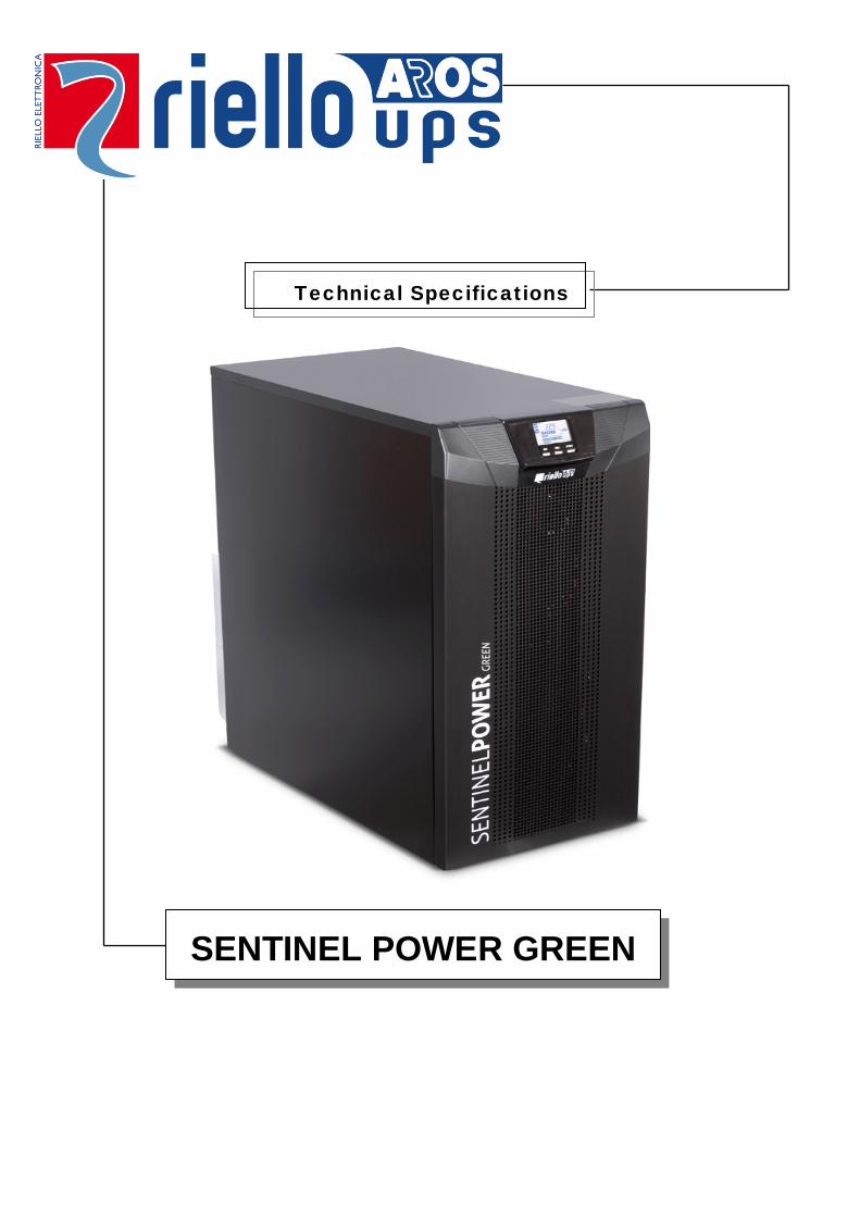
Technical Specifications
SENTINEL POWER GREEN
SENTINEL POWER GREEN
Contents 1 INTRODUCTION .......................................................................................................................................................3 2 UPS VIEWS .............................................................................................................................................................5
Front views .................................................................................................................................................................5 Rear views ..................................................................................................................................................................6 BATTERY BOX ........................................................................................................................................................9
3 GENERAL FEATURES ............................................................................................................................................. 10 4 ACCESSORIES ....................................................................................................................................................... 15 5 OPTIONAL ACCESSORIES ....................................................................................................................................... 16 6 PRODUCT CODES ................................................................................................................................................... 16 7 INSTALLATION ...................................................................................................................................................... 17
Single-phase version ................................................................................................................................................. 18 Three/single-phase versions ...................................................................................................................................... 19
8 TECHNICAL DATA ................................................................................................................................................. 23 9 CHARACTERISTIC CURVES..................................................................................................................................... 27 10 ALIGNMENT OF PANELS ........................................................................................................................................ 29
SPTSPHA2Y13BREN 2
SENTINEL POWER GREEN
1 Introduction The SPH and SPM series of UPS are on-line Multistandard type UPS’s available in power ratings from 6 to 20kVA. The SPH series is available from 8 to 20kVA, and features single-phase or three-phase input with single-phase output, whilst the SPM series is available as 6kVA and provides single-phase input and output only. The only difference between the SPH and SPM series is the input and output phase configurations, and therefore the SPM series is considered to be part of the same family as the SPH series. The cabinet is a tower-type unit, available in two different sizes depending on the power rating. The range of UPS are available within the following enclosures, the 6-10 kVA units are supplied within the small cabinets, along with a matching Battery Box with the same styling as the UPS itself which can house one or two parallel strings of 9 Ah batteries. The Battery Box is not fitted with a charger card as all charging is dealt with by the UPS. The 15-20 kVA versions, have the option for a larger a Battery Box (height 160cm), containing one or two strings of 65 Ah batteries Higher recharging currents for larger battery packs are available using the ER version of UPS. These are supplied with a high power charger card in place of the internal batteries. SPH (and SPM) UPS units are sold under the trade name Sentinel Power Green .
Model SPM 6 SPH 8 SPH 10 SPH 10ER SPH 15 SPH 20
SPH 20ER Nominal power [VA / W] 6000/5400 8000/7200 10000/9000 15000/13500 20000/18000 Input/output configuration * S - S S - S / T - S S - S / T - S S - S / T - S S - S / T - S
* LEGEND: S - S = single-phase in - single-phase out T - S = three-phase in - single-phase out MAIN FEATURES Power ratings from 6 to 20 kVA within 2 cabinet sizes Cabinet type: tower Output power factor 0.9 8-20 kVA: three-phase or single-phase (IN) – single-phase (OUT) Automatic single-phase/three-phase input detection Custom LCD display (as for OD1 series) Efficiency >94% with three-level inverter Available in ER (Extended Runtime) version with a 4.4A (10 kVA) or 5A (20 kVA) high power
battery charger in place of the internal batteries Parallel option for up to 2 units with separate batteries (Parallel option kit with communications
card, parallel cable and installation manual) RS232 and USB ports (only one may be used) with GPSER protocol Compatible with our PowerShield3 and UPSTools software REPO (Remote Emergency Power Off) REMOTE BYPASS command Interface slot for communications cards and optional accessories Firmware can be updated on-site Manual Bypass for maintenance as standard equipment Multistandard mode (On-line, Eco, Smart Active, Stand-by Off, etc.)
SPTSPHA2Y13BREN 3
SENTINEL POWER GREEN
2 programmable IEC 10 A Energy Share sockets Fan control using PWM Back feed protection Upgradable to second output for use as an emergency system. VFI (On-line) / pure sinusoidal waveform during battery-powered operation. Automatic output frequency selection (auto-sensing) Front/rear ventilation Main UPS functions (e.g. bypass thresholds, self-test, alarm buzzer, etc.) are customisable
through the dedicated configuration software Battery expansion connector with integrated protection (SPM 6 and SPH8-10-10ER only) Autonomy can be extended indefinitely using dedicated Battery Boxes or custom battery
cabinets Frequency converter mode with 40% power derating Free running mode with 40% power derating
STANDARD VERSIONS 6000 VA – 5400 W – PF 0.9 – small chassis 8000 VA – 7200 W – PF 0.9 – small chassis 10000 VA – 9000 W – PF 0.9 – small chassis 15000 VA – 13500 W – PF 0.9 – large chassis 20000 VA – 18000 W – PF 0.9 – large chassis
ER VERSIONS 10000 VA – 9000 W – PF 0.9 – 4.4 A charger – small chassis 20000 VA – 18000 W – PF 0.9 – 5 A charger – large chassis
SPTSPHA2Y13BREN 4
SENTINEL POWER GREEN
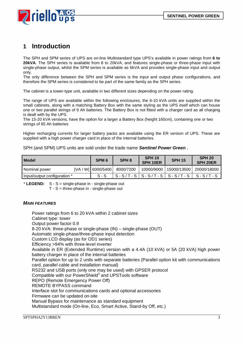
2 UPS views
Front views
SPM 6, SPH 8-10 SPH 15-20
SPM 6, SPH 8-10 SPH 15-20
Display
Multi-function keys
Wheels (front lockable castor, rear fixed)
SPTSPHA2Y13BREN 5
SENTINEL POWER GREEN
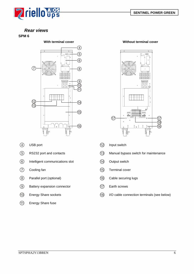
Rear views SPM 6
With terminal cover Without terminal cover
USB port
Input switch
RS232 port and contacts Manual bypass switch for maintenance
Intelligent communications slot Output switch
Cooling fan Terminal cover
Parallel port (optional) Cable securing lugs
Battery expansion connector Earth screws
Energy Share sockets I/O cable connection terminals (see below)
Energy Share fuse
SPTSPHA2Y13BREN 6
SENTINEL POWER GREEN
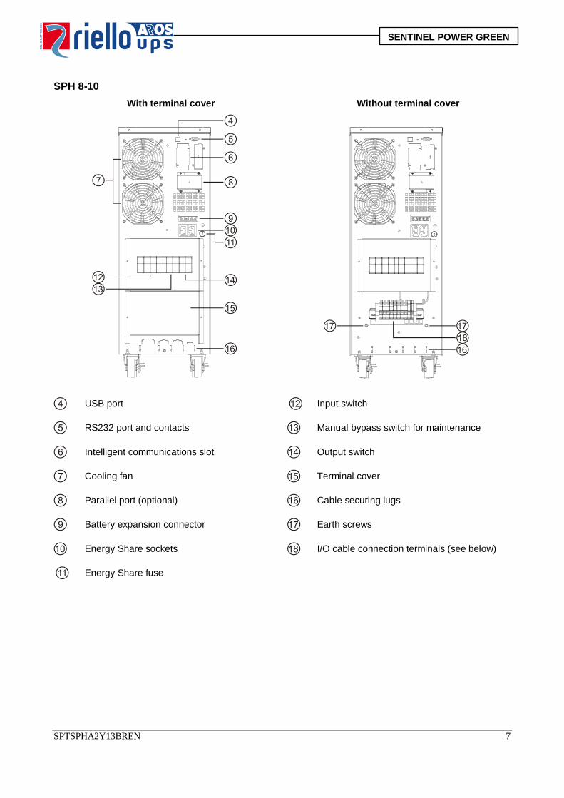
SPH 8-10
With terminal cover Without terminal cover
USB port
Input switch
RS232 port and contacts Manual bypass switch for maintenance
Intelligent communications slot Output switch
Cooling fan Terminal cover
Parallel port (optional) Cable securing lugs
Battery expansion connector Earth screws
Energy Share sockets I/O cable connection terminals (see below)
Energy Share fuse
SPTSPHA2Y13BREN 7
SENTINEL POWER GREEN
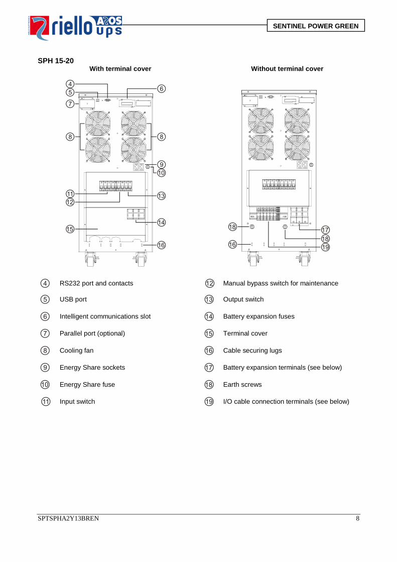
SPH 15-20
With terminal cover Without terminal cover
RS232 port and contacts
Manual bypass switch for maintenance
USB port Output switch
Intelligent communications slot Battery expansion fuses
Parallel port (optional) Terminal cover
Cooling fan Cable securing lugs
Energy Share sockets Battery expansion terminals (see below)
Energy Share fuse Earth screws
Input switch I/O cable connection terminals (see below)
SPTSPHA2Y13BREN 8
SENTINEL POWER GREEN
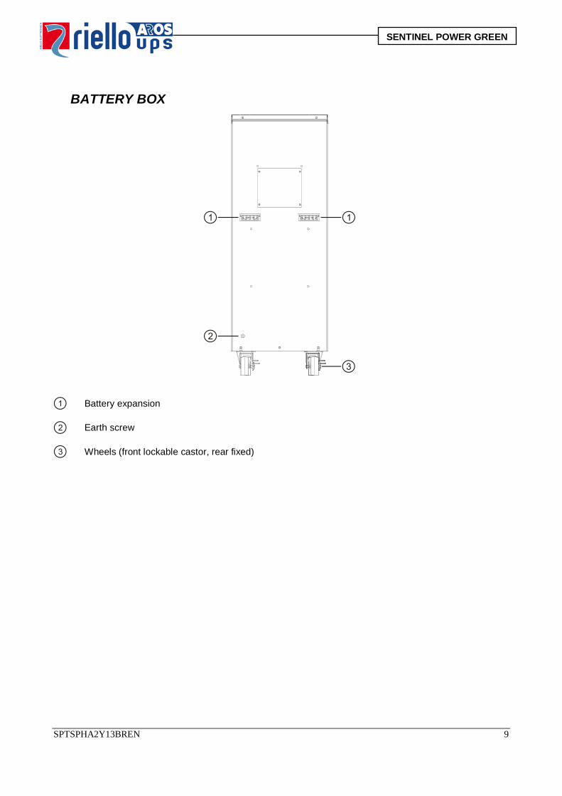
BATTERY BOX
Battery expansion
Earth screw
Wheels (front lockable castor, rear fixed)
SPTSPHA2Y13BREN 9
SENTINEL POWER GREEN
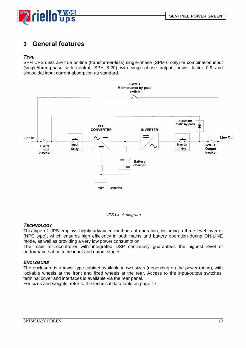
3 General features TYPE SPH UPS units are true on-line (transformer-less) single-phase (SPM 6 only) or combination input (single/three-phase with neutral, SPH 8-20) with single-phase output, power factor 0.9 and sinusoidal input current absorption as standard.
UPS block diagram TECHNOLOGY This type of UPS employs highly advanced methods of operation, including a three-level inverter (NPC type), which ensures high efficiency in both mains and battery operation during ON-LINE mode, as well as providing a very low power consumption. The main microcontroller with integrated DSP continually guarantees the highest level of performance at both the input and output stages. ENCLOSURE The enclosure is a tower-type cabinet available in two sizes (depending on the power rating), with lockable wheels at the front and fixed wheels at the rear. Access to the input/output switches, terminal cover and interfaces is available via the rear panel. For sizes and weights, refer to the technical data table on page 17.
Inverter Relay
Input Relay
Batteries
SPTSPHA2Y13BREN 10
SENTINEL POWER GREEN
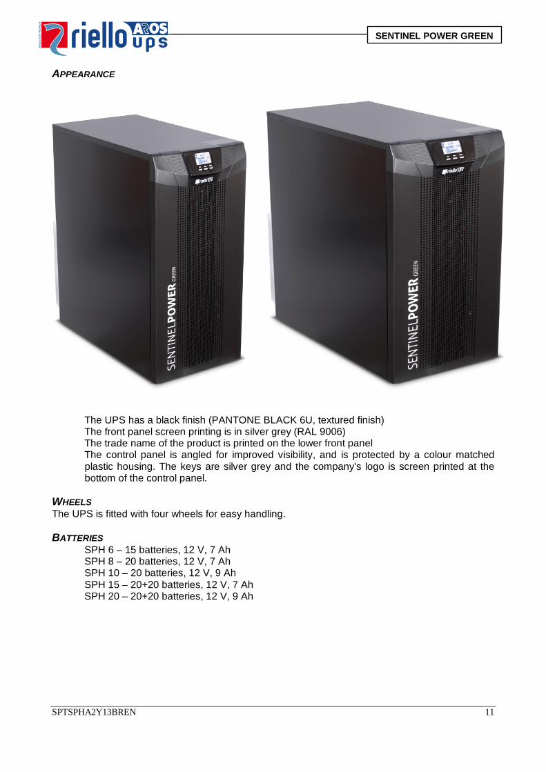
APPEARANCE
The UPS has a black finish (PANTONE BLACK 6U, textured finish) The front panel screen printing is in silver grey (RAL 9006) The trade name of the product is printed on the lower front panel The control panel is angled for improved visibility, and is protected by a colour matched
plastic housing. The keys are silver grey and the company's logo is screen printed at the bottom of the control panel.
WHEELS The UPS is fitted with four wheels for easy handling. BATTERIES
SPH 6 – 15 batteries, 12 V, 7 Ah SPH 8 – 20 batteries, 12 V, 7 Ah SPH 10 – 20 batteries, 12 V, 9 Ah SPH 15 – 20+20 batteries, 12 V, 7 Ah SPH 20 – 20+20 batteries, 12 V, 9 Ah
SPTSPHA2Y13BREN 11
SENTINEL POWER GREEN
Battery types:
CSB 7 Ah/12 V 9 Ah/12 V GP1272F2 HR1234W(F2) UPS123607 UPS12460
YUASA
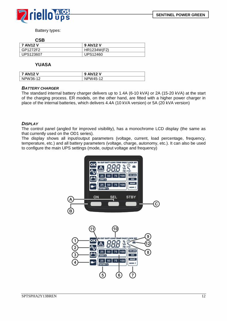
7 Ah/12 V 9 Ah/12 V NPW36-12 NPW45-12 BATTERY CHARGER The standard internal battery charger delivers up to 1.4A (6-10 kVA) or 2A (15-20 kVA) at the start of the charging process. ER models, on the other hand, are fitted with a higher power charger in place of the internal batteries, which delivers 4.4A (10 kVA version) or 5A (20 kVA version) DISPLAY The control panel (angled for improved visibility), has a monochrome LCD display (the same as that currently used on the OD1 series). The display shows all input/output parameters (voltage, current, load percentage, frequency, temperature, etc.) and all battery parameters (voltage, charge, autonomy, etc.). It can also be used to configure the main UPS settings (mode, output voltage and frequency)
SPTSPHA2Y13BREN 12
SENTINEL POWER GREEN
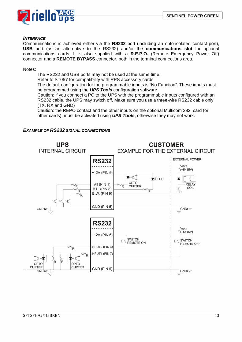
INTERFACE Communications is achieved either via the RS232 port (including an opto-isolated contact port), USB port (as an alternative to the RS232) and/or the communications slot for optional communications cards. It is also supplied with a R.E.P.O. (Remote Emergency Power Off) connector and a REMOTE BYPASS connector, both in the terminal connections area. Notes:
The RS232 and USB ports may not be used at the same time. Refer to ST057 for compatibility with RPS accessory cards The default configuration for the programmable inputs is “No Function”. These inputs must be programmed using the UPS Tools configuration software. Caution: if you connect a PC to the UPS with the programmable inputs configured with an RS232 cable, the UPS may switch off. Make sure you use a three-wire RS232 cable only (TX, RX and GND) Caution: the REPO contact and the other inputs on the optional Multicom 382 card (or other cards), must be activated using UPS Tools, otherwise they may not work.
EXAMPLE OF RS232 SIGNAL CONNECTIONS
SPTSPHA2Y13BREN 13
SENTINEL POWER GREEN
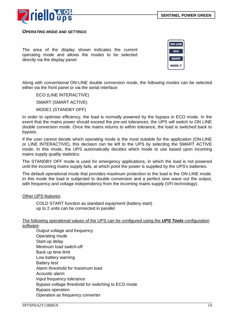
OPERATING MODE AND SETTINGS
The area of the display shown indicates the current operating mode and allows the modes to be selected directly via the display panel.
Along with conventional ON-LINE double conversion mode, the following modes can be selected either via the front panel or via the serial interface:
ECO (LINE INTERACTIVE)
SMART (SMART ACTIVE)
MODE1 (STANDBY OFF)
In order to optimise efficiency, the load is normally powered by the bypass in ECO mode. In the event that the mains power should exceed the pre-set tolerances, the UPS will switch to ON LINE double conversion mode. Once the mains returns to within tolerance, the load is switched back to bypass.
If the user cannot decide which operating mode is the most suitable for the application (ON-LINE or LINE INTERACTIVE), this decision can be left to the UPS by selecting the SMART ACTIVE mode. In this mode, the UPS automatically decides which mode to use based upon incoming mains supply quality statistics.
The STANDBY OFF mode is used for emergency applications, in which the load is not powered until the incoming mains supply fails, at which point the power is supplied by the UPS's batteries.
The default operational mode that provides maximum protection to the load is the ON-LINE mode. In this mode the load is subjected to double conversion and a perfect sine wave out the output, with frequency and voltage independency from the incoming mains supply (VFI technology).
Other UPS features:
COLD START function as standard equipment (battery start) up to 2 units can be connected in parallel
The following operational values of the UPS can be configured using the UPS Tools configuration software:
Output voltage and frequency Operating mode Start-up delay Minimum load switch-off Back up time limit Low battery warning Battery test Alarm threshold for maximum load Acoustic alarm Input frequency tolerance Bypass voltage threshold for switching to ECO mode Bypass operation Operation as frequency converter
SPTSPHA2Y13BREN 14
SENTINEL POWER GREEN
PROTECTIONS Along with the standard internal protection, the units are equipped with back feed protection using current detection on the bypass line (fault bypass). This function, combined with a relay opening to disconnect the inverter and input, satisfies the back feed protection requirements. HOWEVER, the accessory relay board can be installed into the dedicated slot, to associate a particular relay to the battery working or bypass fault event and control an upstream switch if required.
The units are equipped with deep discharge battery protection (switch-off threshold depending on load and installed battery capacity).
4 Accessories UPS
USB cable RS232 cable (pin to pin) Input jumper (combination models only) Software download card (NO CDROM) User manual
BATTERY BOX
Battery expansion cable + 4 polarisation pins Installation and user manual Set of additional stickers
SPTSPHA2Y13BREN 15
SENTINEL POWER GREEN
5 Optional accessories PARALLEL KIT Enables up to 2 units to be connected in parallel. The kit consists of a parallel card which can be installed in the rear of the UPS, a parallel cable for connection to the card, a cover to protect the connectors and an installation and user manual. A kit is required for each connected UPS. EXPANSION CABLE 0CBSU0018… 65CM PLUG/PLUG FOR UPS-BBOX CONNECTION (WAGO) Cable included with standard Battery Boxes.
6 Product codes Product description RPS code (P/N) RPS description
6 kVA 15x7 Ah CSPM6K0AA300 UPS SPM 6 A3 6 kVA (without battery) CSPM6K0AA000 UPS SPM 6 A0
8 kVA 20x7 Ah CSPH8K0AA300 UPS SPH 8 A3 8 kVA (without battery) CSPH8K0AA000 UPS SPH 8 A0
10 kVA 20x9 Ah CSPHK10AA500 UPS SPH 10 A5 10 kVA (without battery) CSPHK10AA000 UPS SPH 10 A0
10 kVA ER CSPHK10ANBER UPS SPH 10 ER 15 kVA 20+20x7 Ah DSPHK15AS100 UPS SPH 15 S1
15 kVA (without battery) DSPHK15AA000 UPS SPH 15 A0 20 kVA 20+20x9 Ah DSPHK20AS200 UPS SPH 20 S2
20 kVA (without battery) DSPHK20AA000 UPS SPH 20 A0 20 kVA ER DSPHK20ANBER UPS SPH 20 ER
Battery Box (6-10 K) empty K070240VM100 BB BBX 700 240 V AB M1
SPH parallel kit YSPHPARA SPH PAR
SPTSPHA2Y13BREN 16
SENTINEL POWER GREEN
7 Installation Caution: with the neutral (N) and phase (P) connections correctly wired to the input and output, the UPS does not affect the existing neutral circuit. The neutral connection resistance is less than 0.1 Ohm. An upstream differential circuit breaker will also be tripped in case of downstream equipment faults. The sensitivity of the circuit breaker must take into account the current leakage within the UPS (around 2 mA) and in the load, which will be summed at the UPS's ground cable.
UPS input Differential Single-phase Type B/Type A Three-phase Type B
The neutral circuit is only affected if an isolating transformer is present or the UPS is operating with the neutral disconnected upstream. Do not connect the output neutral to the input or ground neutral, as this can damage the UPS itself.
Connect to the mains and the load as indicated below: Install a thermomagnetic switch upstream of the UPS (63 A for SPM 6, SPH 8-10-10 ER; 125 A
for SPH 15-20 - 20 ER) with B or C trip curve (4 poles for three-phase connections, 2 poles for single-phase connections).
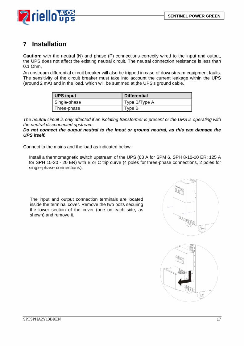
The input and output connection terminals are located inside the terminal cover. Remove the two bolts securing the lower section of the cover (one on each side, as shown) and remove it.
SPTSPHA2Y13BREN 17
SENTINEL POWER GREEN
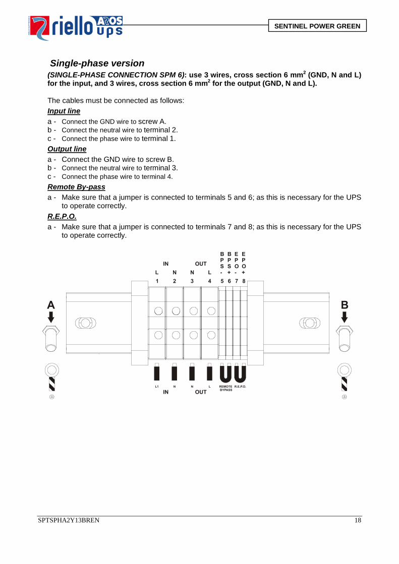
Single-phase version (SINGLE-PHASE CONNECTION SPM 6): use 3 wires, cross section 6 mm2 (GND, N and L)
for the input, and 3 wires, cross section 6 mm2 for the output (GND, N and L). The cables must be connected as follows:
Input line a - Connect the GND wire to screw A. b - Connect the neutral wire to terminal 2. c - Connect the phase wire to terminal 1. Output line a - Connect the GND wire to screw B. b - Connect the neutral wire to terminal 3. c - Connect the phase wire to terminal 4. Remote By-pass a - Make sure that a jumper is connected to terminals 5 and 6; as this is necessary for the UPS
to operate correctly. R.E.P.O. a - Make sure that a jumper is connected to terminals 7 and 8; as this is necessary for the UPS
to operate correctly.
SPTSPHA2Y13BREN 18
SENTINEL POWER GREEN
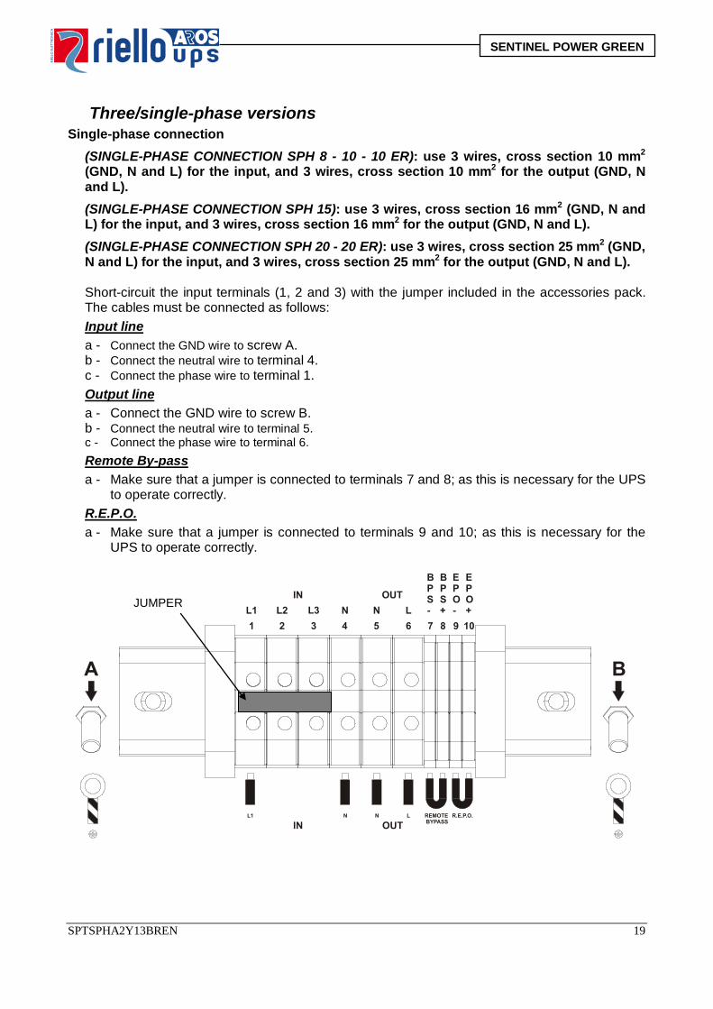
Three/single-phase versions Single-phase connection (SINGLE-PHASE CONNECTION SPH 8 - 10 - 10 ER): use 3 wires, cross section 10 mm2
(GND, N and L) for the input, and 3 wires, cross section 10 mm2 for the output (GND, N and L). (SINGLE-PHASE CONNECTION SPH 15): use 3 wires, cross section 16 mm2 (GND, N and L) for the input, and 3 wires, cross section 16 mm2 for the output (GND, N and L). (SINGLE-PHASE CONNECTION SPH 20 - 20 ER): use 3 wires, cross section 25 mm2 (GND, N and L) for the input, and 3 wires, cross section 25 mm2 for the output (GND, N and L).
Short-circuit the input terminals (1, 2 and 3) with the jumper included in the accessories pack.
The cables must be connected as follows: Input line a - Connect the GND wire to screw A. b - Connect the neutral wire to terminal 4. c - Connect the phase wire to terminal 1. Output line a - Connect the GND wire to screw B. b - Connect the neutral wire to terminal 5. c - Connect the phase wire to terminal 6. Remote By-pass a - Make sure that a jumper is connected to terminals 7 and 8; as this is necessary for the UPS
to operate correctly. R.E.P.O. a - Make sure that a jumper is connected to terminals 9 and 10; as this is necessary for the
UPS to operate correctly.
JUMPER
SPTSPHA2Y13BREN 19
SENTINEL POWER GREEN
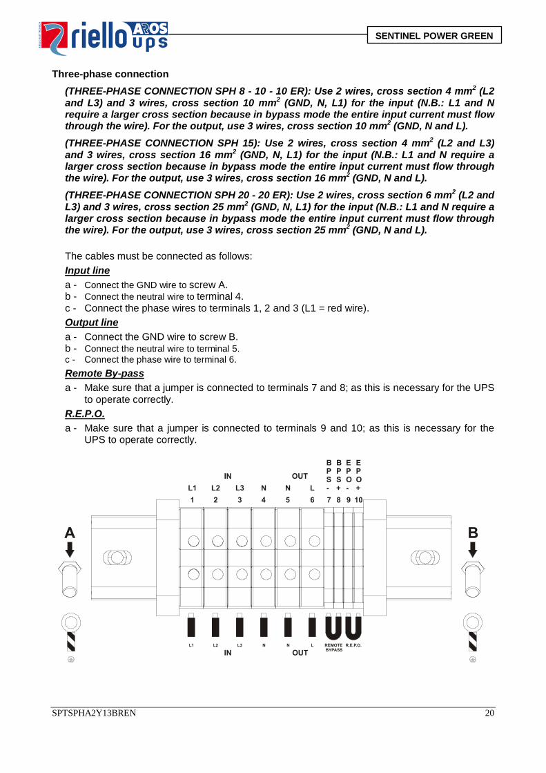
Three-phase connection
(THREE-PHASE CONNECTION SPH 8 - 10 - 10 ER): Use 2 wires, cross section 4 mm2 (L2 and L3) and 3 wires, cross section 10 mm2 (GND, N, L1) for the input (N.B.: L1 and N require a larger cross section because in bypass mode the entire input current must flow through the wire). For the output, use 3 wires, cross section 10 mm2 (GND, N and L). (THREE-PHASE CONNECTION SPH 15): Use 2 wires, cross section 4 mm2 (L2 and L3) and 3 wires, cross section 16 mm2 (GND, N, L1) for the input (N.B.: L1 and N require a larger cross section because in bypass mode the entire input current must flow through the wire). For the output, use 3 wires, cross section 16 mm2 (GND, N and L). (THREE-PHASE CONNECTION SPH 20 - 20 ER): Use 2 wires, cross section 6 mm2 (L2 and L3) and 3 wires, cross section 25 mm2 (GND, N, L1) for the input (N.B.: L1 and N require a larger cross section because in bypass mode the entire input current must flow through the wire). For the output, use 3 wires, cross section 25 mm2 (GND, N and L).
The cables must be connected as follows:
Input line a - Connect the GND wire to screw A. b - Connect the neutral wire to terminal 4. c - Connect the phase wires to terminals 1, 2 and 3 (L1 = red wire). Output line a - Connect the GND wire to screw B. b - Connect the neutral wire to terminal 5. c - Connect the phase wire to terminal 6. Remote By-pass a - Make sure that a jumper is connected to terminals 7 and 8; as this is necessary for the UPS
to operate correctly. R.E.P.O. a - Make sure that a jumper is connected to terminals 9 and 10; as this is necessary for the
UPS to operate correctly.
SPTSPHA2Y13BREN 20
SENTINEL POWER GREEN
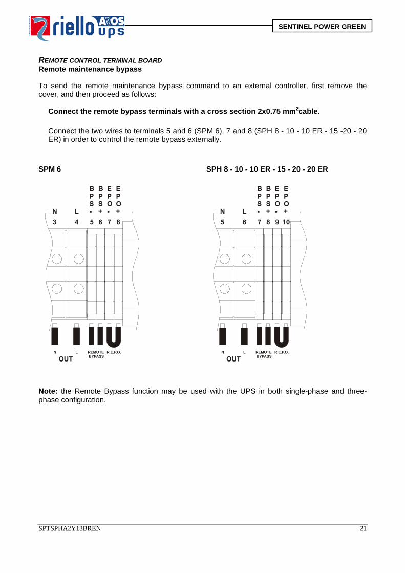
REMOTE CONTROL TERMINAL BOARD Remote maintenance bypass To send the remote maintenance bypass command to an external controller, first remove the cover, and then proceed as follows: Connect the remote bypass terminals with a cross section 2x0.75 mm2cable. Connect the two wires to terminals 5 and 6 (SPM 6), 7 and 8 (SPH 8 - 10 - 10 ER - 15 -20 - 20
ER) in order to control the remote bypass externally. SPM 6 SPH 8 - 10 - 10 ER - 15 - 20 - 20 ER
Note: the Remote Bypass function may be used with the UPS in both single-phase and three-phase configuration.
SPTSPHA2Y13BREN 21
SENTINEL POWER GREEN
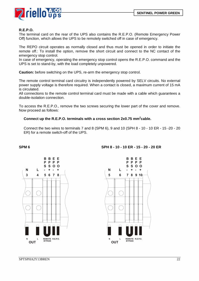
R.E.P.O. The terminal card on the rear of the UPS also contains the R.E.P.O. (Remote Emergency Power Off) function, which allows the UPS to be remotely switched off in case of emergency. The REPO circuit operates as normally closed and thus must be opened in order to initiate the remote off.: To install the option, remove the short circuit and connect to the NC contact of the emergency stop control. In case of emergency, operating the emergency stop control opens the R.E.P.O. command and the UPS is set to stand-by, with the load completely unpowered. Caution: before switching on the UPS, re-arm the emergency stop control. The remote control terminal card circuitry is independently powered by SELV circuits. No external power supply voltage is therefore required. When a contact is closed, a maximum current of 15 mA is circulated. All connections to the remote control terminal card must be made with a cable which guarantees a double-isolation connection. To access the R.E.P.O., remove the two screws securing the lower part of the cover and remove. Now proceed as follows: Connect up the R.E.P.O. terminals with a cross section 2x0.75 mm2cable. Connect the two wires to terminals 7 and 8 (SPM 6), 9 and 10 (SPH 8 - 10 - 10 ER - 15 -20 - 20
ER) for a remote switch-off of the UPS. SPM 6 SPH 8 - 10 - 10 ER - 15 - 20 - 20 ER
SPTSPHA2Y13BREN 22
SENTINEL POWER GREEN
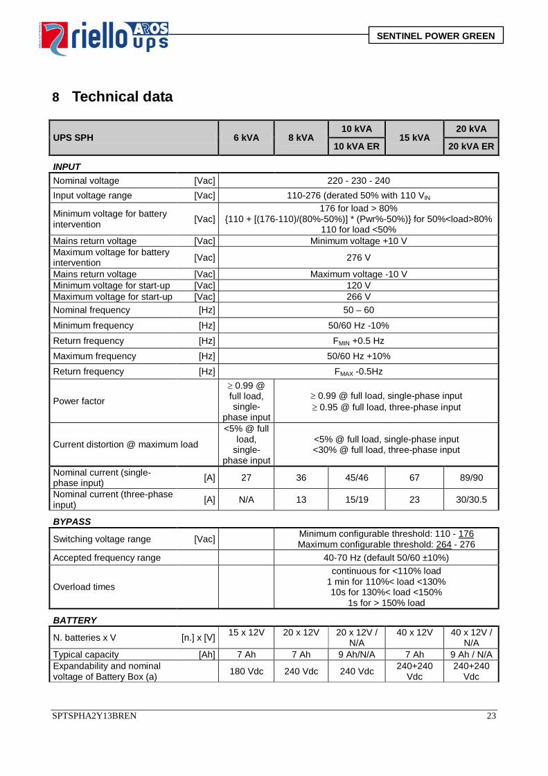
8 Technical data
UPS SPH 6 kVA 8 kVA 10 kVA
15 kVA 20 kVA
10 kVA ER 20 kVA ER
INPUT Nominal voltage [Vac] 220 - 230 - 240 Input voltage range [Vac] 110-276 (derated 50% with 110 VIN
Minimum voltage for battery intervention [Vac]
176 for load > 80% {110 + [(176-110)/(80%-50%)] * (Pwr%-50%)} for 50%<load>80%
110 for load <50% Mains return voltage [Vac] Minimum voltage +10 V Maximum voltage for battery intervention [Vac] 276 V
Mains return voltage [Vac] Maximum voltage -10 V Minimum voltage for start-up [Vac] 120 V Maximum voltage for start-up [Vac] 266 V Nominal frequency [Hz] 50 – 60
Minimum frequency [Hz] 50/60 Hz -10% Return frequency [Hz] FMIN +0.5 Hz Maximum frequency [Hz] 50/60 Hz +10% Return frequency [Hz] FMAX -0.5Hz
Power factor
≥ 0.99 @ full load, single-
phase input
≥ 0.99 @ full load, single-phase input ≥ 0.95 @ full load, three-phase input
Current distortion @ maximum load
<5% @ full load,
single-phase input
<5% @ full load, single-phase input <30% @ full load, three-phase input
Nominal current (single-phase input) [A] 27 36 45/46 67 89/90
Nominal current (three-phase input) [A] N/A 13 15/19 23 30/30.5
BYPASS
Switching voltage range [Vac] Minimum configurable threshold: 110 - 176 Maximum configurable threshold: 264 - 276
Accepted frequency range 40-70 Hz (default 50/60 ±10%)
Overload times
continuous for <110% load 1 min for 110%< load <130% 10s for 130%< load <150%
1s for > 150% load
BATTERY
N. batteries x V [n.] x [V] 15 x 12V 20 x 12V 20 x 12V / N/A
40 x 12V 40 x 12V / N/A
Typical capacity [Ah] 7 Ah 7 Ah 9 Ah/N/A 7 Ah 9 Ah / N/A Expandability and nominal voltage of Battery Box (a) 180 Vdc 240 Vdc 240 Vdc 240+240
Vdc 240+240
Vdc
SPTSPHA2Y13BREN 23
SENTINEL POWER GREEN
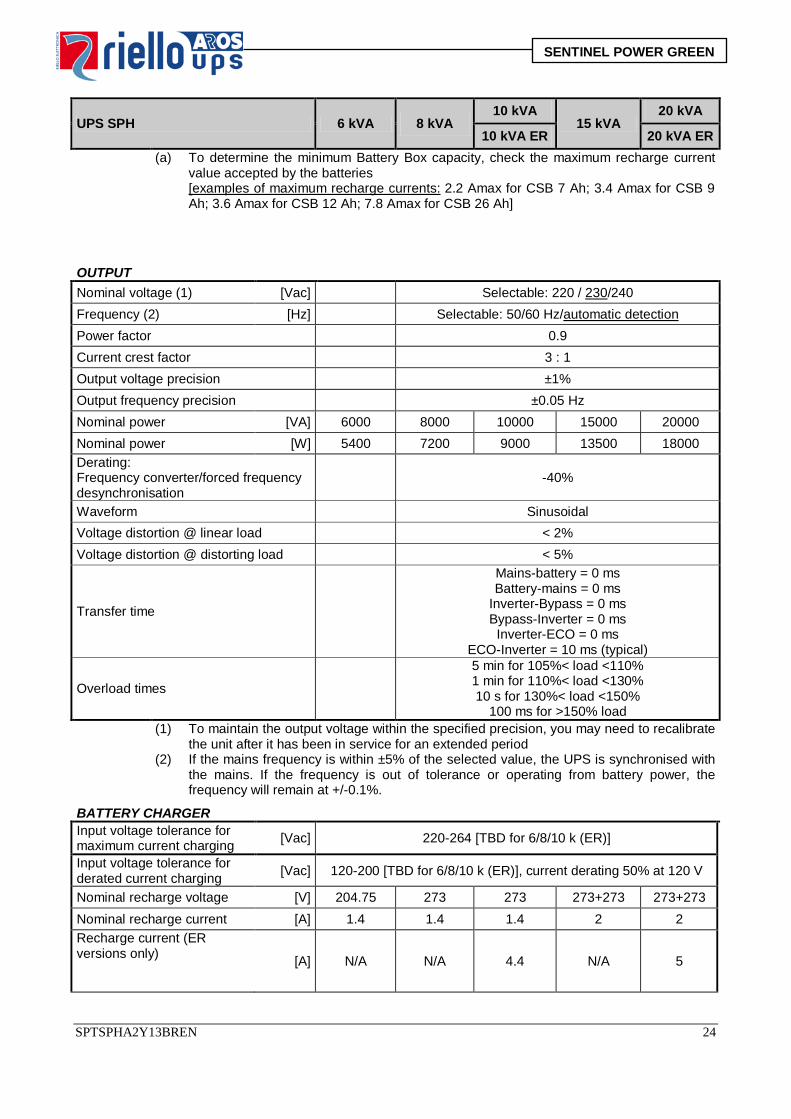
UPS SPH 6 kVA 8 kVA 10 kVA
15 kVA 20 kVA
10 kVA ER 20 kVA ER (a) To determine the minimum Battery Box capacity, check the maximum recharge current
value accepted by the batteries [examples of maximum recharge currents: 2.2 Amax for CSB 7 Ah; 3.4 Amax for CSB 9 Ah; 3.6 Amax for CSB 12 Ah; 7.8 Amax for CSB 26 Ah]
OUTPUT Nominal voltage (1) [Vac] Selectable: 220 / 230/240 Frequency (2) [Hz] Selectable: 50/60 Hz/automatic detection Power factor 0.9 Current crest factor 3 : 1 Output voltage precision ±1% Output frequency precision ±0.05 Hz Nominal power [VA] 6000 8000 10000 15000 20000 Nominal power [W] 5400 7200 9000 13500 18000 Derating: Frequency converter/forced frequency desynchronisation
-40%
Waveform Sinusoidal Voltage distortion @ linear load < 2% Voltage distortion @ distorting load < 5%
Transfer time
Mains-battery = 0 ms Battery-mains = 0 ms
Inverter-Bypass = 0 ms Bypass-Inverter = 0 ms
Inverter-ECO = 0 ms ECO-Inverter = 10 ms (typical)
Overload times
5 min for 105%< load <110% 1 min for 110%< load <130% 10 s for 130%< load <150%
100 ms for >150% load (1) To maintain the output voltage within the specified precision, you may need to recalibrate
the unit after it has been in service for an extended period (2) If the mains frequency is within ±5% of the selected value, the UPS is synchronised with
the mains. If the frequency is out of tolerance or operating from battery power, the frequency will remain at +/-0.1%.
BATTERY CHARGER Input voltage tolerance for maximum current charging [Vac] 220-264 [TBD for 6/8/10 k (ER)]
Input voltage tolerance for derated current charging [Vac] 120-200 [TBD for 6/8/10 k (ER)], current derating 50% at 120 V
Nominal recharge voltage [V] 204.75 273 273 273+273 273+273 Nominal recharge current [A] 1.4 1.4 1.4 2 2 Recharge current (ER versions only)
[A] N/A
N/A
4.4 N/A 5
SPTSPHA2Y13BREN 24
SENTINEL POWER GREEN
UPS SPH 6 kVA 8 kVA 10 kVA
15 kVA 20 kVA
10 kVA ER 20 kVA ER
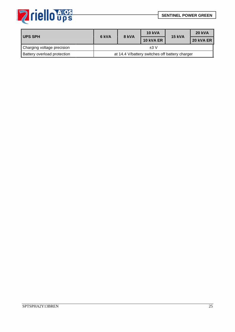
Charging voltage precision ±3 V Battery overload protection at 14.4 V/battery switches off battery charger
SPTSPHA2Y13BREN 25
SENTINEL POWER GREEN
UPS SPH 6 kVA 8 kVA 10 kVA
15 kVA 20 kVA
10 kVA ER 20 kVA ER
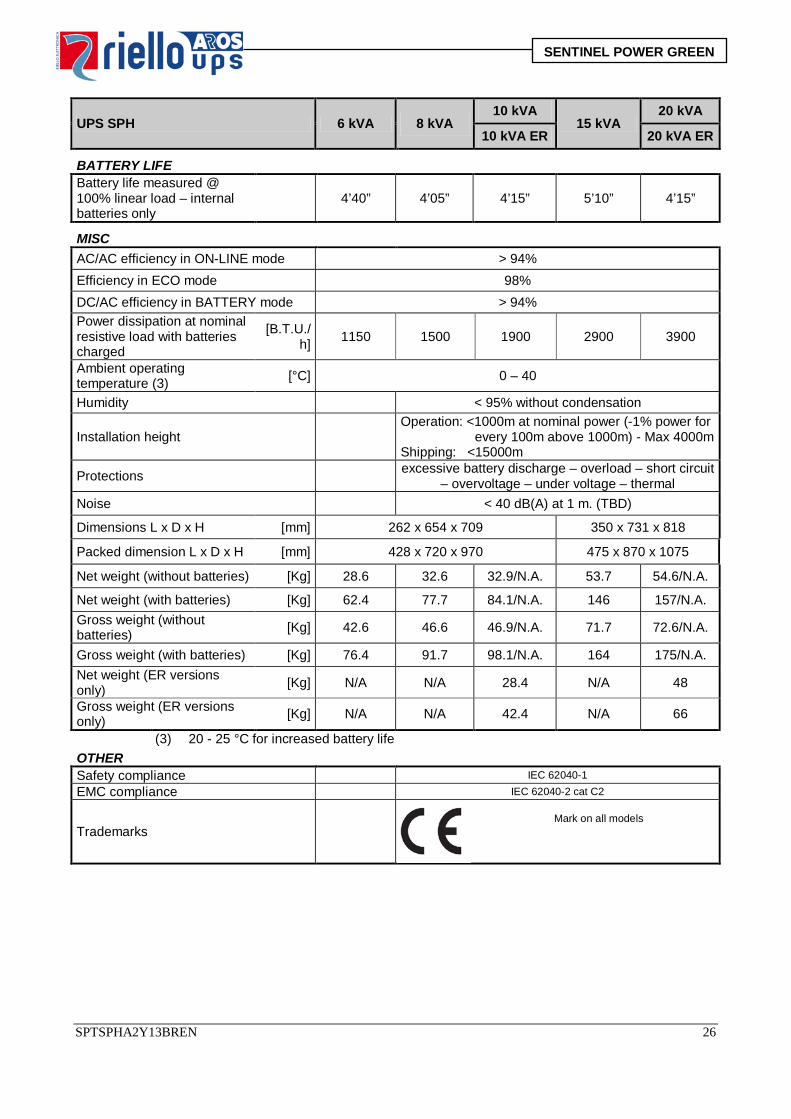
BATTERY LIFE Battery life measured @ 100% linear load – internal batteries only
4’40” 4’05” 4’15” 5’10” 4’15”
MISC AC/AC efficiency in ON-LINE mode > 94% Efficiency in ECO mode 98% DC/AC efficiency in BATTERY mode > 94% Power dissipation at nominal resistive load with batteries charged
[B.T.U./h] 1150 1500 1900 2900 3900
Ambient operating temperature (3) [°C] 0 – 40
Humidity < 95% without condensation
Installation height Operation: <1000m at nominal power (-1% power for every 100m above 1000m) - Max 4000m Shipping: <15000m
Protections excessive battery discharge – overload – short circuit – overvoltage – under voltage – thermal
Noise < 40 dB(A) at 1 m. (TBD)
Dimensions L x D x H [mm] 262 x 654 x 709 350 x 731 x 818
Packed dimension L x D x H [mm] 428 x 720 x 970 475 x 870 x 1075
Net weight (without batteries) [Kg] 28.6 32.6 32.9/N.A. 53.7 54.6/N.A.
Net weight (with batteries) [Kg] 62.4 77.7 84.1/N.A. 146 157/N.A. Gross weight (without batteries) [Kg] 42.6 46.6 46.9/N.A. 71.7 72.6/N.A.
Gross weight (with batteries) [Kg] 76.4 91.7 98.1/N.A. 164 175/N.A. Net weight (ER versions only) [Kg] N/A N/A 28.4 N/A 48
Gross weight (ER versions only) [Kg] N/A N/A 42.4 N/A 66
(3) 20 - 25 °C for increased battery life OTHER Safety compliance IEC 62040-1 EMC compliance IEC 62040-2 cat C2
Trademarks
Mark on all models
SPTSPHA2Y13BREN 26
SENTINEL POWER GREEN
BATTERY BOX BATTERY BOX empty 180 V
9 Ah 180 V 18 Ah
240 V 9 Ah
240 V 18 Ah
Nominal battery voltage [Vdc] 0 Vdc 180 Vdc 180 Vdc 240 Vdc 240 Vdc N. batteries/V [n.]/[V] 0/12 V 15/12 V 15+15/12 V 20/12 V 20+20/12 V Typical capacity Ah 0 9 18 9 18 Dimensions L x D x H [mm] 262x654x709
Packed dimensions L x D x H [mm] 428 x 720 x 970
net weight [Kg] 27 64.5 102 77 127
Gross weight [Kg] 40.9 78.4 115.9 90.9 140.9 NOTES: Same dimensions and styling as UPS. Empty units may be configured with 9 or 18Ah.
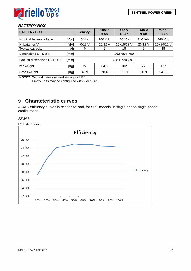
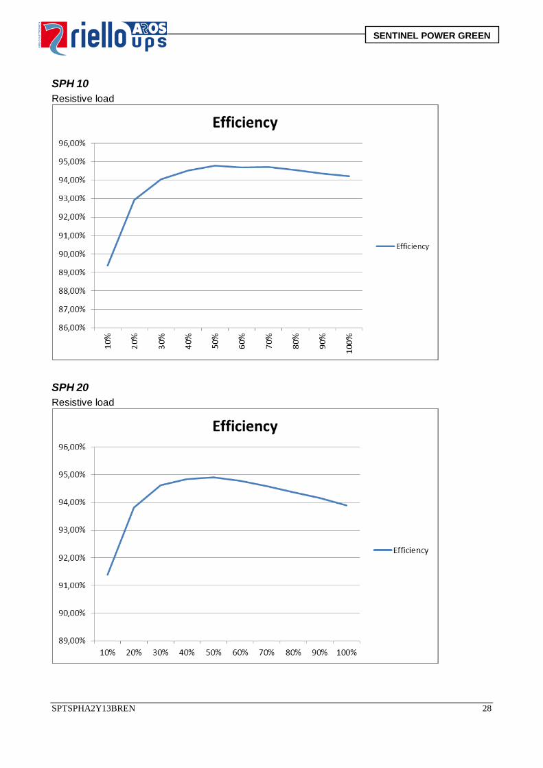
9 Characteristic curves AC/AC efficiency curves in relation to load, for SPH models, in single-phase/single-phase configuration. SPM 6 Resistive load
SPTSPHA2Y13BREN 27
SENTINEL POWER GREEN
SPH 10 Resistive load
SPH 20 Resistive load
SPTSPHA2Y13BREN 28
SENTINEL POWER GREEN
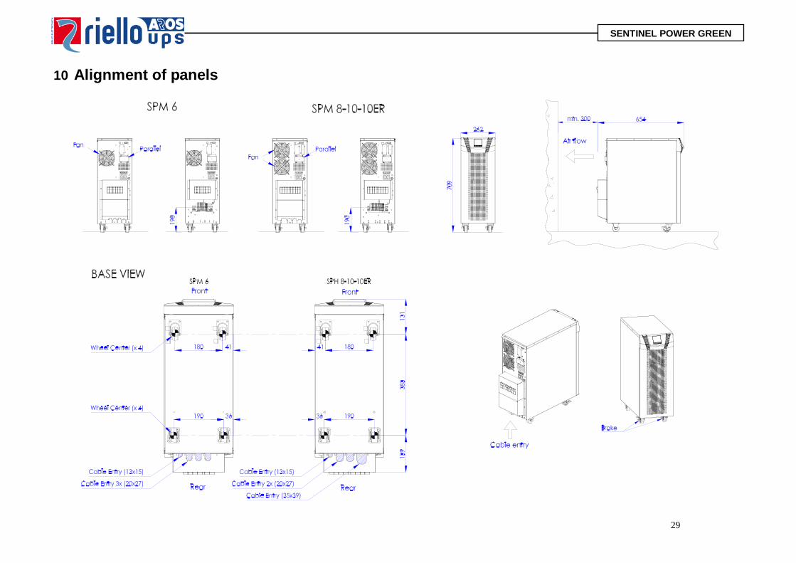
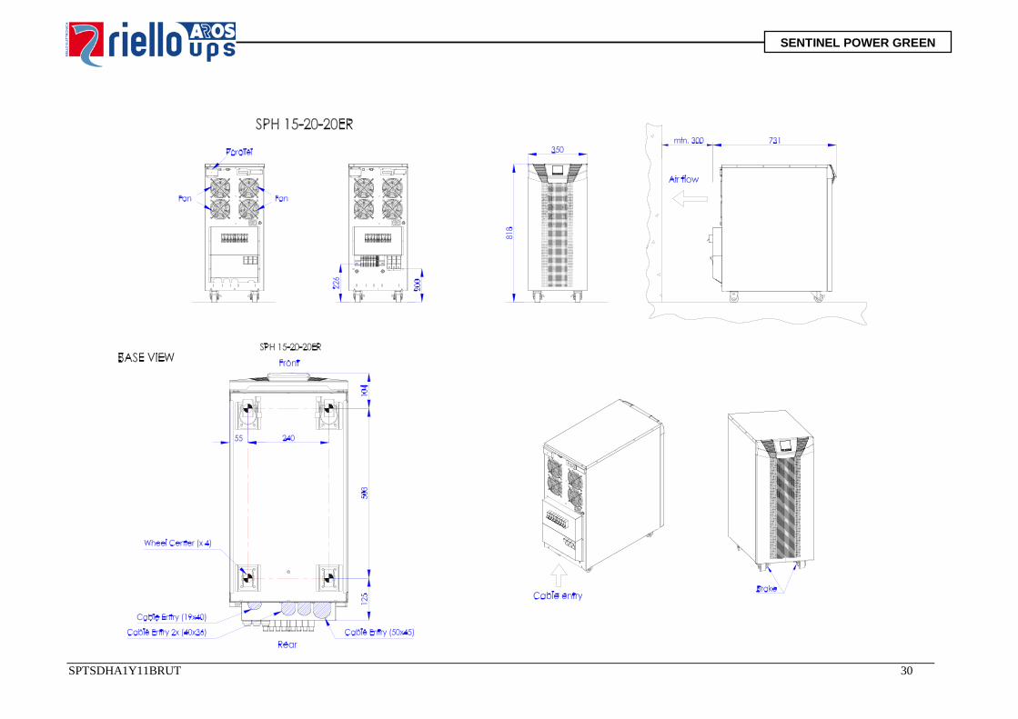
10 Alignment of panels
29
SENTINEL POWER GREEN
SPTSDHA1Y11BRUT 30