Embed Size (px)
Citation preview
SENSORS & SYSTEMS
Authority in Displacement Measurement
OC
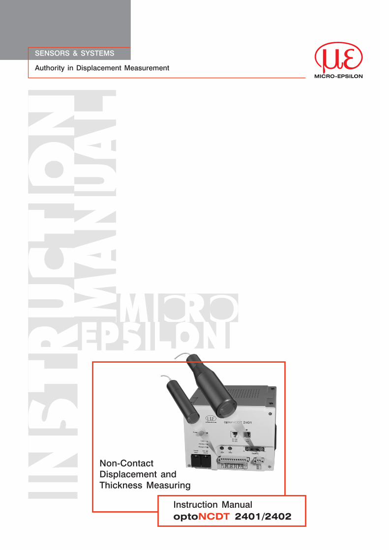
Non-ContactDisplacement andThickness Measuring
Instruction ManualoptoNCDT 2401/2402

MICRO-EPSILONMESSTECHNIKGmbH & Co. KG
Königbacher Strasse 15
D-94496 Ortenburg
Tel. 0 85 42/1 68-0 Fax 0 85 42/1 68-90e-mail [email protected]
www.micro-epsilon.com
Certificated acc. to DIN EN ISO 9001: 2008V1.2
optoNCDT2401
Contents
1. Safety ...................................................................................... 51.1 Symbols Used........................................................................................ 51.2 Warnings ................................................................................................ 51.3 Notes on CE Identification ..................................................................... 51.4 Proper Use ............................................................................................. 61.5 Proper Environment ............................................................................... 62. Functional Principle, Technical Data ..................................... 72.1 Short Description ................................................................................... 72.2 Measurement Principle ........................................................................... 82.3 Glossary ................................................................................................. 82.4 Typical Applications ............................................................................... 82.5 Sensor .................................................................................................... 92.6 Control Elements Controller ................................................................... 92.7 Light Source......................................................................................... 102.8 Technical Data IFS2401 ........................................................................ 102.9 Technical Data IFS2402 ........................................................................ 113. Delivery ............................................................................... 123.1 Supplied Items ..................................................................................... 123.2 Storage ................................................................................................ 124. Installation and Assembly .................................................. 124.1 Mounting and Dimensions of Sensors.................................................. 134.1.1 Start of Measuring Range .................................................................... 154.1.2 Circumferential Clamping ..................................................................... 154.2 Sensor Cable ....................................................................................... 164.3 Controller Dimensions .......................................................................... 174.4 Electrical Connections ......................................................................... 174.4.1 Power supply ....................................................................................... 174.4.2 RS232/RS422 Interface ........................................................................ 174.4.3 USB Interface ....................................................................................... 184.4.4 Analog Output ...................................................................................... 184.4.5 Synchronization ................................................................................... 184.4.6 Digital I/O, Encoder ............................................................................. 195. Operation............................................................................. 215.1 Commissioning .................................................................................... 215.2 Displacement Measuring ...................................................................... 215.3 Thickness Measurement ....................................................................... 215.4 Acquiring the Dark Signal .................................................................... 225.5 Analog Output ...................................................................................... 225.6 Adjustment of the LED Brightness........................................................ 235.7 Adjustment of the Measuring Rate ....................................................... 235.8 Light Intensity ....................................................................................... 235.9 Synchronized Controller and Encoder Data ......................................... 245.10 Triggering ............................................................................................. 245.10.1 Trigger Modes ...................................................................................... 245.10.2 Trigger Input ......................................................................................... 245.10.3 Start Trigger ......................................................................................... 255.10.4 Level Trigger ......................................................................................... 255.10.5 Edge Trigger ........................................................................................ 255.10.6 Latch Trigger ........................................................................................ 265.10.7 Software Trigger ................................................................................... 265.10.8 Maximum Trigger Frequency ............................................................... 265.11 Response Time .................................................................................... 275.12 Double Frequency ............................................................................... 286. Serial Interface.................................................................... 306.1 Data Format ......................................................................................... 316.2 Command Syntax ................................................................................ 32
optoNCDT2401
6.3 Data Transmission Formats .................................................................. 326.3.1 ASCII .................................................................................................... 326.3.2 Binary ................................................................................................... 336.4 Transmitted Data .................................................................................. 346.4.1 Available Data ...................................................................................... 346.4.2 Meaning of the Data ............................................................................. 346.4.3 Data Selection...................................................................................... 356.5 Data Decoding ..................................................................................... 366.5.1 Displacement Measuring Mode ........................................................... 366.5.2 Thickness Measuring Mode ................................................................. 366.5.3 Decoding the Barycenter Values .......................................................... 376.5.4 Decoding the State Data ..................................................................... 376.6 Commands .......................................................................................... 386.6.1 Sensor Selection .................................................................................. 386.6.2 Measuring Rate .................................................................................... 386.6.3 Displacement and Thickness Measurement ......................................... 406.6.4 Analog Output ...................................................................................... 406.6.5 Dark Signal .......................................................................................... 416.6.6 Fast Dark Signal ................................................................................... 416.6.7 Refractive Index .................................................................................... 426.6.8 Light Source Brightness ....................................................................... 426.6.9 Averaging ............................................................................................. 426.6.10 Spectral Averaging ............................................................................... 436.6.11 Hold Last Valid Value ........................................................................... 436.6.12 Trigger Functions ................................................................................. 436.6.13 Get Controller Configuration ................................................................ 456.6.14 Detection Threshold ............................................................................. 466.6.15 Light Source Test ................................................................................. 476.6.16 Auto-adaptive Dark Signal ................................................................... 476.6.17 Auto-adaptive Light Source Brightness ................................................ 476.6.18 First Signal Maximum ........................................................................... 486.6.19 Watchdog ............................................................................................ 506.6.20 Save the Controller Configuration ........................................................ 506.6.21 Serial Number, Software Version .......................................................... 506.6.22 Reset Encoder Counter ........................................................................ 506.6.23 Setting the Zero Values ........................................................................ 516.6.24 Missing Signal in Thickness Measurement Mode ................................. 516.6.25 Selection Light Source ......................................................................... 526.6.26 Switch on Double Frequency ............................................................... 526.6.27 Select Frequencies for Double Frequency ........................................... 526.6.28 Transmitted Intensity in Double Frequency Mode................................ 526.7 Command List ...................................................................................... 536.8 HyperTerminal ...................................................................................... 557. IFD2401 Tool ....................................................................... 567.1 Preparation for Measurements ............................................................. 567.2 Installation ............................................................................................ 567.3 Working with the IFD2401 Tool ............................................................ 587.3.1 Elements in the Main Window .............................................................. 587.3.2 Interface ............................................................................................... 587.3.3 CCD ..................................................................................................... 597.3.4 Displacement Measuring ...................................................................... 597.3.5 Thickness Measuring ............................................................................ 598. Warranty .............................................................................. 609. Decommissioning, Disposal ............................................... 6010. Troubleshooting .................................................................. 6111. Reset to Factory Setting..................................................... 6212. Maintenance ........................................................................ 62
5optoNCDT2401
1. SafetyThe handling of the system assumes knowledge of the instruction manual.
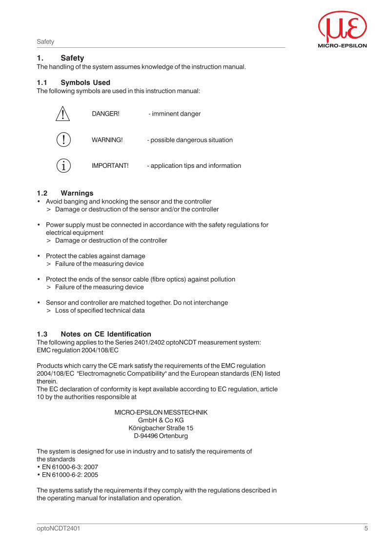
1.1 Symbols UsedThe following symbols are used in this instruction manual:
DANGER! - imminent danger
WARNING! - possible dangerous situation
IMPORTANT! - application tips and information
1.2 Warnings• Avoid banging and knocking the sensor and the controller
> Damage or destruction of the sensor and/or the controller
• Power supply must be connected in accordance with the safety regulations forelectrical equipment> Damage or destruction of the controller
• Protect the cables against damage> Failure of the measuring device
• Protect the ends of the sensor cable (fibre optics) against pollution> Failure of the measuring device
• Sensor and controller are matched together. Do not interchange> Loss of specified technical data
1.3 Notes on CE IdentificationThe following applies to the Series 2401/2402 optoNCDT measurement system:EMC regulation 2004/108/EC
Products which carry the CE mark satisfy the requirements of the EMC regulation2004/108/EC "Electromagnetic Compatibility" and the European standards (EN) listedtherein.The EC declaration of conformity is kept available according to EC regulation, article10 by the authorities responsible at
MICRO-EPSILON MESSTECHNIKGmbH & Co KG
Königbacher Straße 15D-94496 Ortenburg
The system is designed for use in industry and to satisfy the requirements ofthe standards• EN 61000-6-3: 2007• EN 61000-6-2: 2005
The systems satisfy the requirements if they comply with the regulations described inthe operating manual for installation and operation.
Safety
6optoNCDT2401
Safety
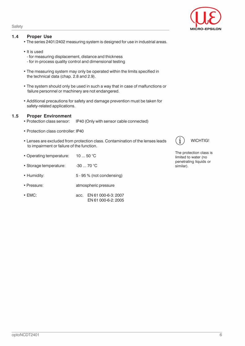
1.4 Proper Use• The series 2401/2402 measuring system is designed for use in industrial areas.
• It is used- for measuring displacement, distance and thickness- for in-process quality control and dimensional testing
• The measuring system may only be operated within the limits specified inthe technical data (chap. 2.8 and 2.9).
• The system should only be used in such a way that in case of malfunctions orfailure personnel or machinery are not endangered.
• Additional precautions for safety and damage prevention must be taken forsafety-related applications.
1.5 Proper Environment• Protection class sensor: IP40 (Only with sensor cable connected)
• Protection class controller: IP40
• Lenses are excluded from protection class. Contamination of the lenses leadsto impairment or failure of the function.
• Operating temperature: 10 ... 50 °C
• Storage temperature: -30 ... 70 °C
• Humidity: 5 - 95 % (not condensing)
• Pressure: atmospheric pressure
• EMC: acc. EN 61 000-6-3: 2007EN 61 000-6-2: 2005
WICHTIG!
The protection class islimited to water (nopenetrating liquids orsimilar).
7optoNCDT2401
Functional Principle, Technical Data
2. Functional Principle, Technical Data
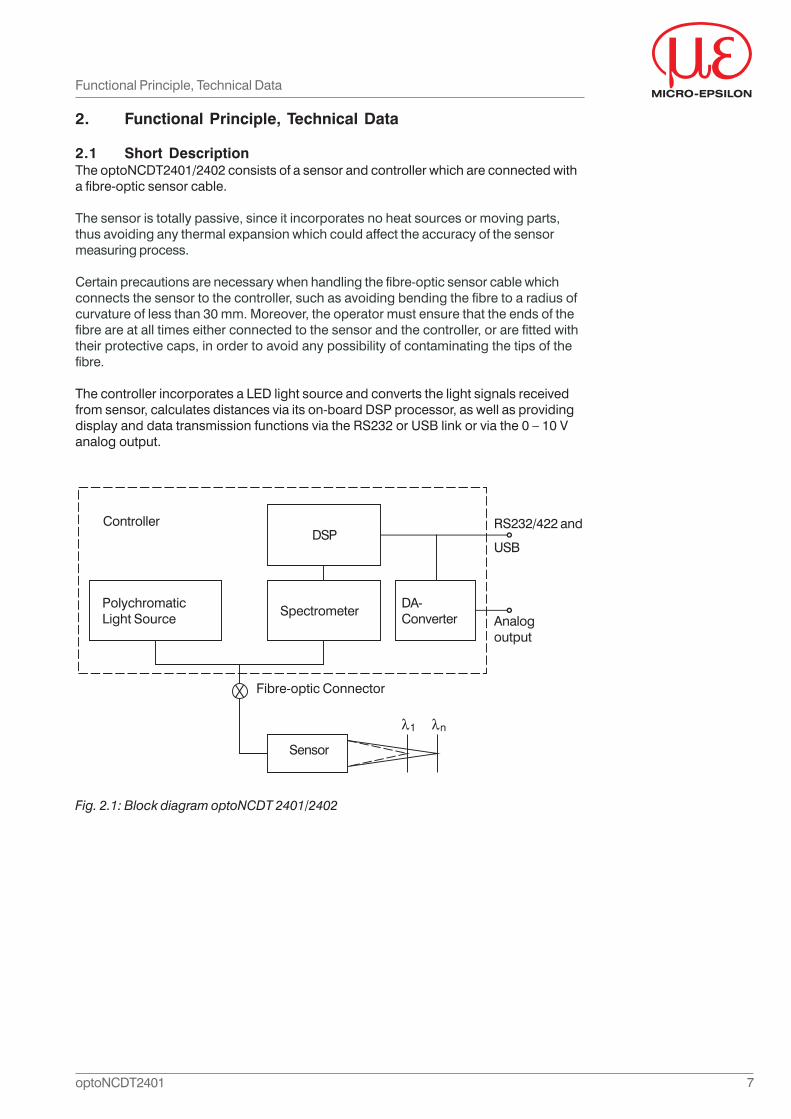
2.1 Short DescriptionThe optoNCDT2401/2402 consists of a sensor and controller which are connected witha fibre-optic sensor cable.
The sensor is totally passive, since it incorporates no heat sources or moving parts,thus avoiding any thermal expansion which could affect the accuracy of the sensormeasuring process.
Certain precautions are necessary when handling the fibre-optic sensor cable whichconnects the sensor to the controller, such as avoiding bending the fibre to a radius ofcurvature of less than 30 mm. Moreover, the operator must ensure that the ends of thefibre are at all times either connected to the sensor and the controller, or are fitted withtheir protective caps, in order to avoid any possibility of contaminating the tips of thefibre.
The controller incorporates a LED light source and converts the light signals receivedfrom sensor, calculates distances via its on-board DSP processor, as well as providingdisplay and data transmission functions via the RS232 or USB link or via the 0 – 10 Vanalog output.
Fig. 2.1: Block diagram optoNCDT 2401/2402
Controller
Analogoutput
RS232/422 and
USB
PolychromaticLight Source
DSP
SpectrometerDA-Converter
Fibre-optic Connector
Sensor
8optoNCDT2401
2.2 Measurement Principle
Polychromatic white light is focused onto the target surface by a multi-lens opticalsystem.The lenses are arranged such that the white light is dispersed into amonochromatic light by controlled chromatic deviation. A certain distance is assignedto each wavelength by a factory calibration. Only the wavelength which is exactlyfocussed on the target is used for the measurement. This light reflected from the targetsurface is passed via a confocal aperture to the receiver which detects and processesthe spectral changes.
This unique measuring principle enables displacements and distances to be measuredwith high precision. Both diffuse and specular surfaces can be measured. With transpa-rent materials a one sided thickness measurement can be accomplished along with thedistance measurement. Since the emitter and receiver are arranged in one axis,shadowing is avoided.
Due to excellent resolution and small spot diameters surface structures can bemeasured. Note that measurement incertainly may occur, if the structure dimensionsare similar to the spot diameter, or if the acceptable tilt on a structure, e.g. turning rill,is exceeded.
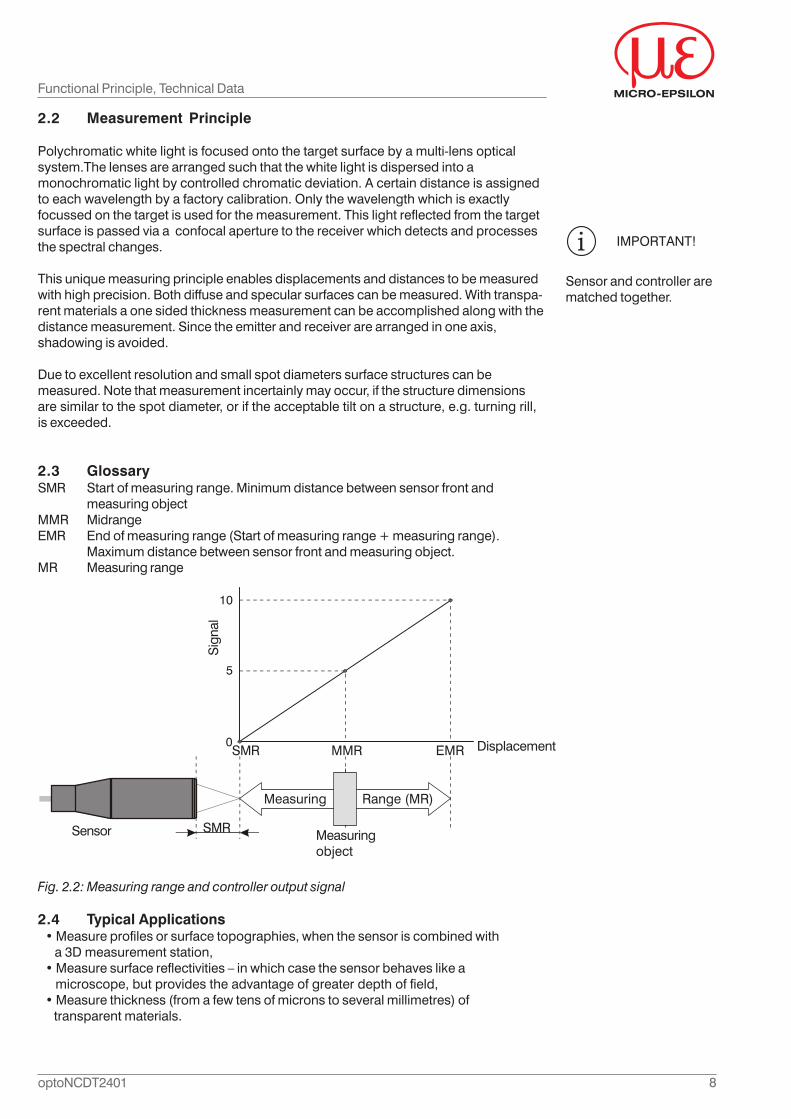
2.3 GlossarySMR Start of measuring range. Minimum distance between sensor front and
measuring objectMMR MidrangeEMR End of measuring range (Start of measuring range + measuring range).
Maximum distance between sensor front and measuring object.MR Measuring range
Fig. 2.2: Measuring range and controller output signal
2.4 Typical Applications• Measure profiles or surface topographies, when the sensor is combined with a 3D measurement station,• Measure surface reflectivities – in which case the sensor behaves like a microscope, but provides the advantage of greater depth of field,• Measure thickness (from a few tens of microns to several millimetres) of transparent materials.
IMPORTANT!
Sensor and controller arematched together.
10
5
0
Functional Principle, Technical Data
Measuringobject
Sensor
Measuring Range (MR)
SMR MMR EMR Displacement
SMR
Sig
nal
9optoNCDT2401
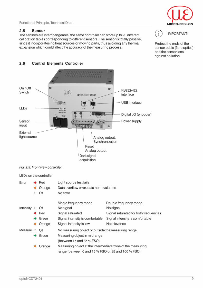
Fig. 2.3: Front view controller
LEDs on the controller
Functional Principle, Technical Data
Light source test fails
Data overflow error, data non-evaluable
No error
No signal
Signal saturated
Signal intensity is comfortable
Signal intensity is low
No measuring object or outside the measuring range
Measuring object in midrange
(between 15 and 85 % FSO)
Measuring object at the intermediate zone of the measuring
range (between 0 and 15 % FSO or 85 and 100 % FSO)
2.6 Control Elements Controller
Analog output,Synchronization
On / OffSwitch
Sensorinput
LEDs
Externallight source
RS232/422interface
Digital I/O (encoder)
USB interface
Power supply
ResetAnalog output
Dark signalacquisition
2.5 SensorThe sensors are interchangeable: the same controller can store up to 20 differentcalibration tables corresponding to different sensors. The sensor is totally passive,since it incorporates no heat sources or moving parts, thus avoiding any thermalexpansion which could affect the accuracy of the measuring process.
IMPORTANT!
Protect the ends of thesensor cable (fibre optics)and the sensor lensagainst pollution.
Error
Off
Red
Green
Orange
Intensity
Measure Off
Green
Orange
Single frequency mode Double frequency modeNo signal
Signal saturated for both frequencies
Signal intensity is comfortable
No relevance
Red
Orange
Off
10optoNCDT2401
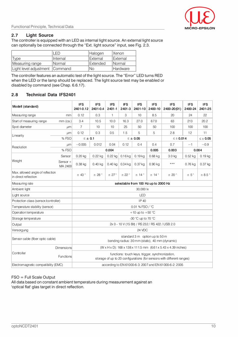
2.8 Technical Data IFS2401
Functional Principle, Technical Data
2.7 Light SourceThe controller is equipped with an LED as internal light source. An external light sourcecan optionally be connected through the “Ext. light source” input, see Fig. 2.3.
LED Halogen XenonType Internal External ExternalMeasuring range Normal Extended NormalLight level adjustment Command No Hardware
The controller features an automatic test of the light source. The “Error” LED turns REDwhen the LED or the lamp should be replaced. The light source test may be enabled ordisabled by command (see Chap. 6.6.17).
FSO = Full Scale OutputAll data based on constant ambient temperature during measurement against an'optical flat' glas target in direct reflection.
IFS 2401-0.12
IFS 2401-0.4
IFS 2401-1
IFS 2401-3
IFS 2401-10
IFS 2400-10
IFS 2400-20(01)
IFS 2400-24
IFS 2401-25
Measuring range mm 0.12 0.3 1 3 10 8.5 20 24 22
Start of measuring range mm (ca.) 3.4 10.5 10.0 16.3 27.0 67.0 63 213 20.2
Spot diameter μm 7 10 10 25 50 50 100 100 100
μm 0.12 0.3 0.5 1.5 5 5 2.8 12 11
% FSO ≤ ± 0.05
μm ~0.005 0.012 0.04 0.12 0.4 0.4 0.7 ~1 ~0.9
% FSO 0.005 0.003
Sensor 0.20 kg 0.22 kg 0.22 kg 0.16 kg 0.19 kg 0.68 kg 3.0 kg 0.52 kg 0.19 kg
Sensor +MA 2400
0.38 kg 0.40 kg 0.40 kg 0.34 kg 0.37 kg 0.90 kg *** 0.76 kg 0.37 kg
± 43 ° ± 28 ° ± 27 ° ± 22 ° ± 14 ° ± 14 ° ± 20 ° ± 5 ° ± 8.5 °
Output
Dimensions
Functions
Electromagnetic compatibility (EMC) according to EN 61000-6-3: 2007 and EN 61000-6-2: 2005
Sensor cable (fiber optic cable) standard 3 m option up to 50 m
bending radius: 30 mm (static), 40 mm (dynamic)
Controller
(W x H x D): 168 x 138 x 111.5 mm (6.61 x 5.43 x 4.39 inches)
functions: touch keys, trigger, synchronization, storage of up to 20 configurations (for sensors with different ranges)
Storage temperature -30 °C up to 70 °C
2x 0 - 10 V (15 Bit) / RS 232 / RS 422 / USB 2.0
Versorgung 24 VDC
Temperature stability (sensor) 0.01 % FSO / °C
Operation temperature +10 up to +50 °C
Light source LED
Protection class (sensor/controller) IP 40
0.004 0.004
Ambient light 30,000 lx
Modell (standard)
Linearity
Measuring rate
≤ ± 0.1
Max. allowed angle of reflection in direct reflection
selectable from 100 Hz up to 2000 Hz
Resolution
Weight
≤ ± 0.05 ≤ ± 0.014
11optoNCDT2401
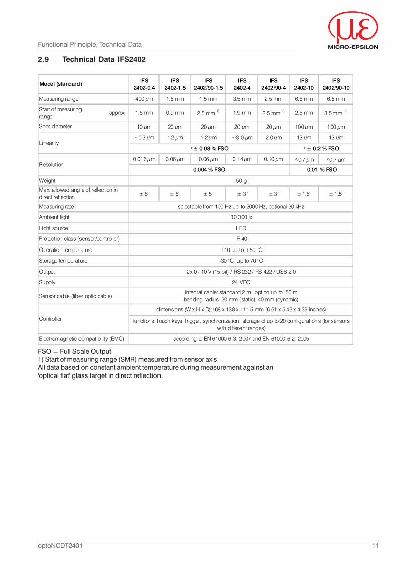
2.9 Technical Data IFS2402
Functional Principle, Technical Data
FSO = Full Scale Output1) Start of measuring range (SMR) measured from sensor axisAll data based on constant ambient temperature during measurement against an'optical flat' glass target in direct reflection.
IFS2402-0.4
IFS2402-1.5
IFS2402/90-1.5
IFS2402-4
IFS2402/90-4
IFS2402-10
IFS2402/90-10
400 μm 1.5 mm 1.5 mm 3.5 mm 2.5 mm 6.5 mm 6.5 mm
Start of measuringrange
approx. 1.5 mm 0.9 mm 2.5 mm 1) 1.9 mm 2.5 mm 1 ) 2.5 mm 3.5 mm 1)
10 μm 20 μm 20 μm 20 μm 20 μm 100 μm 100 μm
~0.3 μm 1.2 μm 1.2 μm ~3.0 μm 2.0 μm 13 μm 13 μm
0.016 μm 0.06 μm 0.06 μm 0.14 μm 0.10 μm ≤0.7 μm ≤0.7 μm
Weight
± 8° ± 5° ± 5° ± 3° ± 3° ± 1.5° ± 1.5°
Measuring rate
Output
Model (standard)
-30 °C up to 70 °C
2x 0 - 10 V (15 bit) / RS 232 / RS 422 / USB 2.0
24 VDC
IP 40
+10 up to +50 °C
≤± 0.2 % FSO
0.01 % FSO0.004 % FSO
Measuring range
according to EN 61000-6-3: 2007 and EN 61000-6-2: 2005
Max. allowed angle of reflection in direct reflection
Sensor cable (fiber optic cable)
selectable from 100 Hz up to 2000 Hz, optional 30 kHz
functions: touch keys, trigger, synchronization, storage of up to 20 configurations (for sensors with different ranges)
Controller
30.000 lxAmbient light
integral cable: standard 2 m option up to 50 mbending radius: 30 mm (static), 40 mm (dynamic)
Electromagnetic compatibility (EMC)
Spot diameter
Linearity
Resolution
dimensions (W x H x D):168 x 138 x 111.5 mm (6.61 x 5.43 x 4.39 inches)
50 g
≤± 0.08 % FSO
LED
Supply
Protection class (sensor/controller)
Light source
Storage temperature
Operation temperature
12optoNCDT2401
3. Delivery
3.1 Supplied Items1 Sensor1 Sensor cable1 Controller1 Test log1 Instruction manual
Once unpacked, check immediately for completeness and transit damage. If damageis found or the shipment is incomplete, please contact the manufacturer or supplierimmediately.
3.2 StorageStorage temperature: -30 to +70 °C (-22 °F to +158 °F)Relative humidit: 5 to 95 % (non-condensing)
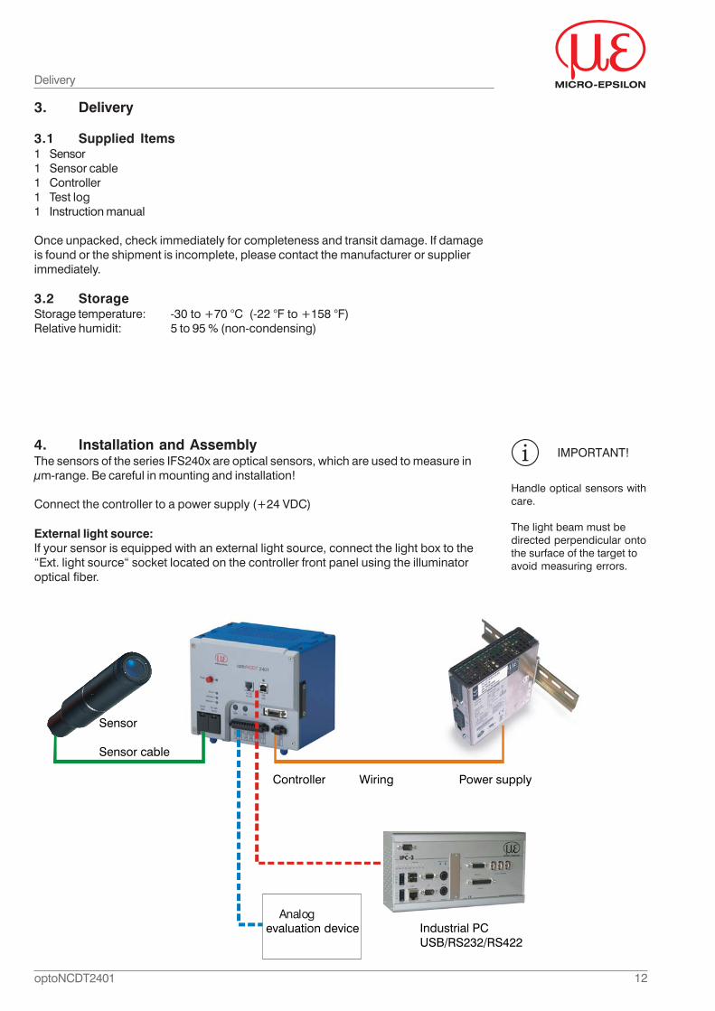
4. Installation and AssemblyThe sensors of the series IFS240x are optical sensors, which are used to measure inμm-range. Be careful in mounting and installation!
Connect the controller to a power supply (+24 VDC)
IMPORTANT!
Handle optical sensors withcare.
The light beam must bedirected perpendicular ontothe surface of the target toavoid measuring errors.
Delivery
External light source:If your sensor is equipped with an external light source, connect the light box to the“Ext. light source“ socket located on the controller front panel using the illuminatoroptical fiber.
Industrial PCUSB/RS232/RS422
Sensor
Sensor cable
Controller Wiring Power supply
Analog evaluation device
13optoNCDT2401
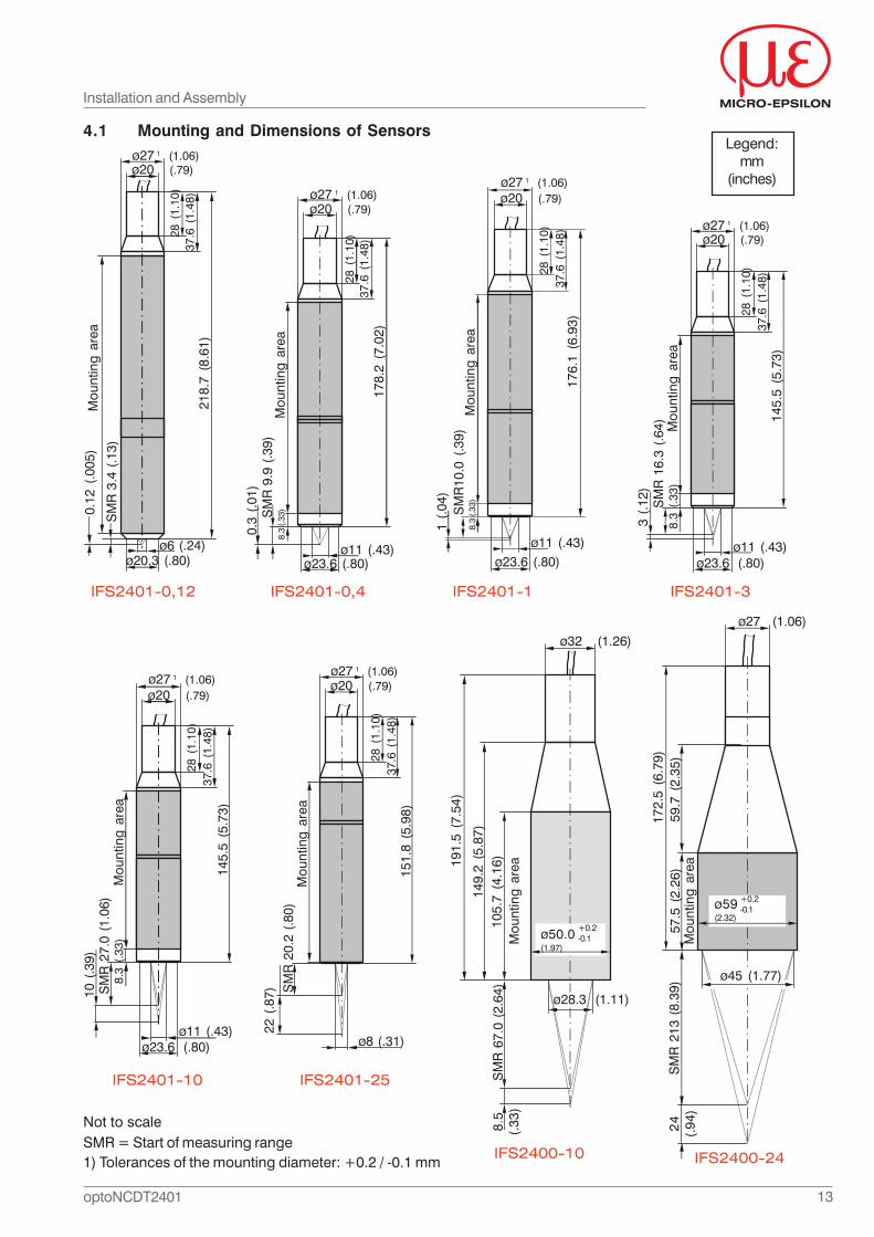
4.1 Mounting and Dimensions of Sensors
IFS2401-0,12 IFS2401-0,4 IFS2401-1 IFS2401-3
IFS2401-25
Installation and Assembly
ø6 (.24)
28 (
1.10
)ø27 1 (1.06)
SM
R 3
.4 (
.13)
ø20 (.79)
37.6
(1.
48)
Mou
ntin
g ar
ea
ø20.3 (.80)
218.
7 (8
.61)
0.12
(.0
05)
ø11 (.43)ø23.6 (.80)
ø27 1 (1.06)ø20 (.79)
28 (
1.10
)37
.6 (
1.48
)17
8.2
(7.0
2)
SM
R 9
.9 (
.39)
0.3
(.01
)
Mou
ntin
g ar
ea8.
3 (.3
3)
ø23.6 (.80)17
6.1
(6.9
3)
28 (
1.10
)
ø27 1 (1.06)ø20 (.79)
37.6
(1.
48)
SM
R10
.0 (
.39)
Mou
ntin
g ar
ea
ø11 (.43)
8.3
(.33)
1 (.
04)
Not to scaleSMR = Start of measuring range
145.
5 (5
.73)
SM
R 1
6.3
(.64
)
ø23.6 (.80)
3 (.
12)
28 (
1.10
)
ø27 1 (1.06)ø20 (.79)
37.6
(1.
48)
Mou
ntin
g ar
ea
ø11 (.43)
8.3
(.33
)
IFS2401-10
ø23.6 (.80)
28 (
1.10
)
ø20 (.79)
37.6
(1.
48)
Mou
ntin
g ar
ea
ø27 1 (1.06)
SM
R 2
7.0
(1.0
6)10
(.3
9)
ø11 (.43)
8.3
(.33
)
145.
5 (5
.73)
151.
8 (5
.98)
SM
R 2
0.2
(.80
)
28 (
1.10
)
ø27 1 (1.06)ø20 (.79)
37.6
(1.
48)
Mou
ntin
g ar
ea
22 (
.87)
ø8 (.31)
1) Tolerances of the mounting diameter: +0.2 / -0.1 mm
Legend:mm
(inches)
IFS2400-10
191.
5 (7
.54)
ø50.0(1.97)
149.
2 (5
.87)
Mou
ntin
g ar
ea10
5.7
(4.1
6)S
MR
67.
0 (2
.64)
8.5
(.33
)
ø28.3 (1.11)
ø32 (1.26)
+0.2-0.1
IFS2400-24
172.
5 (6
.79)
ø27 (1.06)
ø59(2.32)
59.7
(2.
35)
Mou
ntin
g ar
ea57
.5 (
2.26
)S
MR
213
(8.
39)
24
(.94
)
ø45 (1.77)
+0.2-0.1
14optoNCDT2401
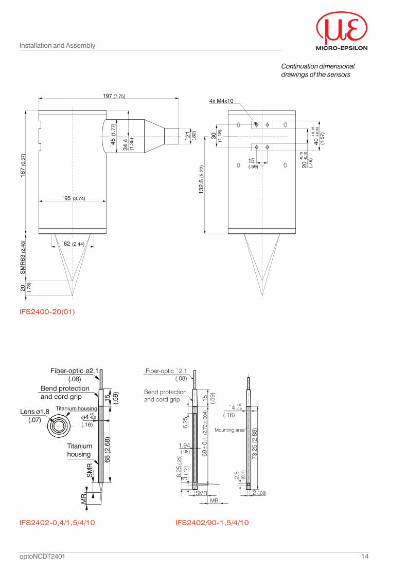
Installation and Assembly
Continuation dimensionaldrawings of the sensors
IFS2402/90-1,5/4/10IFS2402-0,4/1,5/4/10
Fiber-optic ø2.1(.08)
Bend protectionand cord grip
Lens ø1.8(.07)
Titanium housing
Titaniumhousing
MR
SM
R
68 (2
.68)
15 (.59)
ø4(.16)
+0-0.2
SMR
Fiber-optic ¯2.1(.08)
3 (.1
2)6.
256.
25 (.
25)
15 (.59)Bend protection
and cord grip
MR
69±
0.1
(2.7
2±.0
04) ¯4
(.16)
Mounting area
73.2
5 (2
.88)
1.94(.08)
+0-0.2
2.5
(0.1
)
2 (.08)
¯62 (2.44)
197 (7.75)
¯95 (3.74)
20 (.7
8)S
MR
63 (
2.48
)16
7 (6
.57)
¯21
(.82
)
¯45
(1.
77)
15 (.59) 20 (.
78)-0
,15
-0,1
0
40 (1.5
7)+0,
15+
0,05
30(1
.18)
132.
6 (5
.22)
4x M4x10
34.4
(1.3
5)
IFS2400-20(01)
15optoNCDT2401
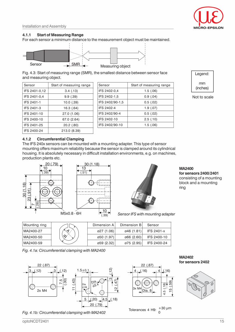
4.1.1 Start of Measuring RangeFor each sensor a minimum distance to the measurement object must be maintained.
Fig. 4.3: Start of measuring range (SMR), the smallest distance between sensor faceand measuring object.
4.1.2 Circumferential ClampingThe IFS 240x sensors can be mounted with a mounting adapter. This type of sensormounting offers maximum reliability because the sensor is clamped around its cylindricalhousing. It is absolutely necessary in difficult installation environments, e.g. on machines,production plants etc.
Sensor Measuring objectSMR
rosneS egnargnirusaemfotratS
21,0-1042SFI )31.(4.3
4,0-1042SFI )93.(9.9
1-1042SFI )93.(0.01
3-1042SFI )46.(3.61
01-1042SFI )60.1(0.72
01-0042SFI )46.2(0.76
52-1042SFI )08.(2.02
42-0042SFI )93.8(0.312
Installation and Assembly
rosneS egnargnirusaemfotratS
4,0-2042SFI )60.(5.1
5,1-2042SFI )40.(9.0
5,1-09/2042SFI )20.(5.0
4-2042SFI )70.(9.1
4-09/2042SFI )20.(5.0
01-2042SFI )01.(5.2
01-09/2042SFI )60.(5.1
Fig. 4.1a: Circumferential clamping with MA2400
Sensor IFS with mounting adapter
20 (.79)10
(.39)
30 (1.18)13
(.51)
10(.39)
7(.
28)23
(.91
)30
(1.1
8)
M5x0.8 - 6H
Legend:
mm(inches)
Not to scale
MA2400for sensors 2400/2401consisting of a mountingblock and a mountingring
MA2402for sensors 2402
gnirgnitnuoM AnoisnemiD BnoisnemiD rosneS
72-0042AM )60.1(72ø )18.1(64ø x-1042SFI
05-0042AM )79.1(05ø )06.2(66ø 01-0042SFI
95-0042AM )23.2(95ø )59.2(57ø 42-0042SFI
A
B
Fig. 4.1b: Circumferential clamping with MA2402
22 (.87)
3 (.12) 4 (.16)1.5±0.13 (.12)
7.5
(.30
)
2x M4 11 (
.43)
20 (.79)
5 (.20) 4.5 (.18)
12 (
.47)
3 (
.12)
Dia.4 H9
Dia.
ø3.4
4 (.16)
Dia. 8
22 (.87)
15 (
.59)
4.5
(.18
)
3x M4
Tolerances 4 H9: +30 μm0
16optoNCDT2401
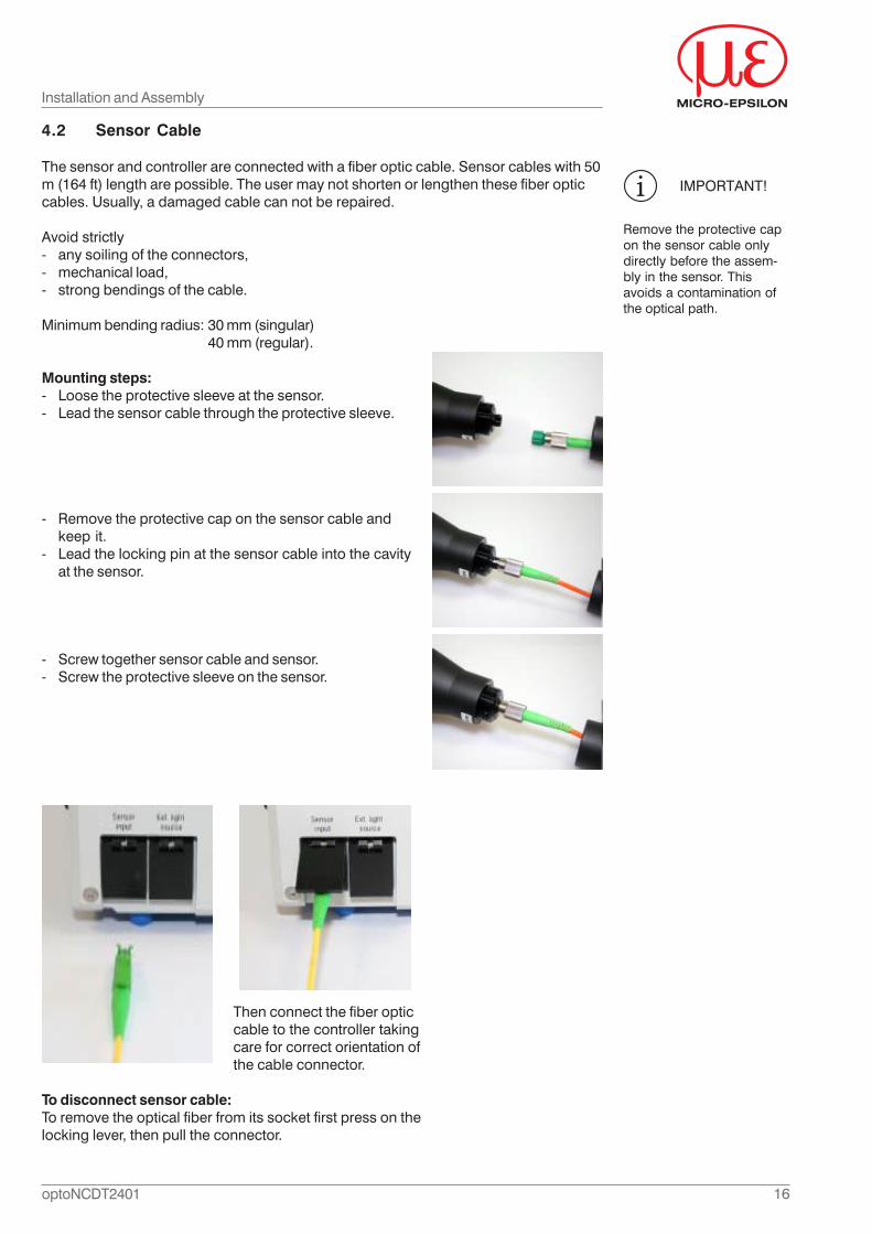
4.2 Sensor Cable
The sensor and controller are connected with a fiber optic cable. Sensor cables with 50m (164 ft) length are possible. The user may not shorten or lengthen these fiber opticcables. Usually, a damaged cable can not be repaired.
Avoid strictly- any soiling of the connectors,- mechanical load,- strong bendings of the cable.
Minimum bending radius: 30 mm (singular)40 mm (regular).
Mounting steps:- Loose the protective sleeve at the sensor.- Lead the sensor cable through the protective sleeve.
- Remove the protective cap on the sensor cable andkeep it.
- Lead the locking pin at the sensor cable into the cavityat the sensor.
- Screw together sensor cable and sensor.- Screw the protective sleeve on the sensor.
IMPORTANT!
Remove the protective capon the sensor cable onlydirectly before the assem-bly in the sensor. Thisavoids a contamination ofthe optical path.
Installation and Assembly
Then connect the fiber opticcable to the controller takingcare for correct orientation ofthe cable connector.
To disconnect sensor cable:To remove the optical fiber from its socket first press on thelocking lever, then pull the connector.
17optoNCDT2401
Installation and Assembly
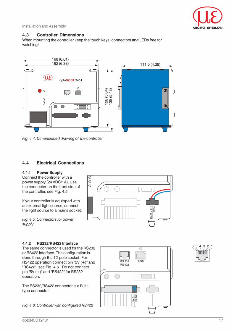
4.3 Controller DimensionsWhen mounting the controller keep the touch keys, connectors and LEDs free forwatching!
4.4 Electrical Connections
4.4.1 Power SupplyConnect the controller with apower supply (24 VDC/1A). Usethe connector on the front side ofthe controller, see Fig. 4.5.
If your controller is equipped withan external light source, connectthe light source to a mains socket.
4.4.2 RS232/RS422 InterfaceThe same connector is used for the RS232or RS422 interface. The configuration isdone through the 12-pole socket. ForRS422 operation connect pin "5V (+)" and"RS422", see Fig. 4.6. Do not connectpin "5V (+)" and "RS422" for RS232operation.
The RS232/RS422 connector is a RJ11type connector.
Fig. 4.4: Dimensioned drawing of the controller
opto 2401NCDT
168 (6.61)162 (6.38)
128
(5.0
4)13
8 (5
.43)
111.5 (4.39)
Fig. 4.5: Connectors for powersupply
DC
24 V
(+
)G
ND
Fig. 4.6: Controller with configured RS422
6 5 4 3 2 1
RS 232 USBRS 422
5V (
+)
RS
422
18optoNCDT2401
Tab. 4.1: Pin assignment RS232
Tab. 4.2: Pin assignment RS422
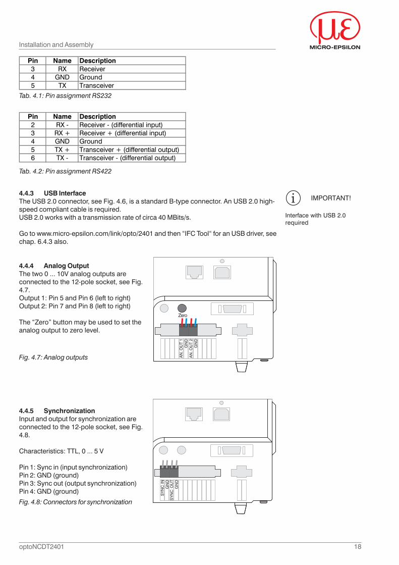
4.4.3 USB InterfaceThe USB 2.0 connector, see Fig. 4.6, is a standard B-type connector. An USB 2.0 high-speed compliant cable is required.USB 2.0 works with a transmission rate of circa 40 MBits/s.
Go to www.micro-epsilon.com/link/opto/2401 and then “IFC Tool“ for an USB driver, seechap. 6.4.3 also.
4.4.4 Analog OutputThe two 0 ... 10V analog outputs areconnected to the 12-pole socket, see Fig.4.7.Output 1: Pin 5 and Pin 6 (left to right)Output 2: Pin 7 and Pin 8 (left to right)
The “Zero” button may be used to set theanalog output to zero level.
4.4.5 SynchronizationInput and output for synchronization areconnected to the 12-pole socket, see Fig.4.8.
Characteristics: TTL, 0 ... 5 V
Pin 1: Sync in (input synchronization)Pin 2: GND (ground)Pin 3: Sync out (output synchronization)Pin 4: GND (ground)
Fig. 4.7: Analog outputs AN
. OU
T 1
GN
DA
N. O
UT
2G
ND
Zero
Installation and Assembly
SY
NC
ING
ND
SY
NC
OU
TG
ND
Fig. 4.8: Connectors for synchronization
Pin Name Description3 RX Receiver4 GND Ground5 TX Transceiver
Pin Name Description2 RX - Receiver - (differential input)3 RX + Receiver + (differential input)4 GND Ground5 TX + Transceiver + (differential output)6 TX - Transceiver - (differential output)
Interface with USB 2.0required
IMPORTANT!
19optoNCDT2401
Installation and Assembly
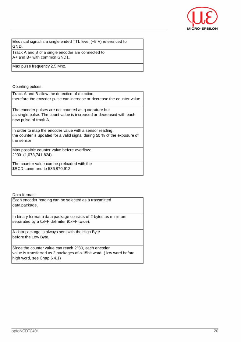
4.4.6 Digital I/O, Encoder
Up to three encoders can be connectedto the 20-pole Digital I/O connector, seeFig. 4.10. Connector type: MDR.
Fig. 4.10: Connector for encoders
Tab. 4.3: Pin assignment Digital I/O
Pin 8 up to Pin 19 are not connected on the Digital I/O.
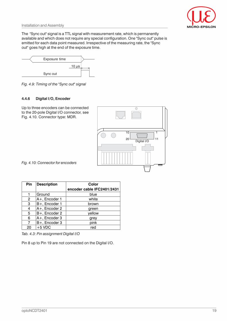
The "Sync out" signal is a TTL signal with measurement rate, which is permanentlyavailable and which does not require any special configuration. One "Sync out" pulse isemitted for each data point measured. Irrespective of the measuring rate, the "Syncout" goes high at the end of the exposure time.
Fig. 4.9: Timing of the "Sync out" signal
Exposure time
10 μs
Sync out
Pin Description Colorencoder cable IFC2401/2431
1 Ground blue2 A+, Encoder 1 white3 B+, Encoder 1 brown4 A+, Encoder 2 green5 B+, Encoder 2 yellow6 A+, Encoder 3 grey7 B+, Encoder 3 pink
20 +5 VDC red
20optoNCDT2401
Electrical signal is a single ended TTL level (+5 V) referenced to GND.Track A and B of a single encoder are connected toA+ and B+ with common GND1.
Max pulse frequency 2.5 Mhz.
Counting pulses:
Track A and B allow the detection of direction, therefore the encoder pulse can increase or decrease the counter value.
The encoder pulses are not counted as quadrature but as single pulse. The count value is increased or decreased with each new pulse of track A.
In order to map the encoder value with a sensor reading, the counter is updated for a valid signal during 50 % of the exposure of the sensor.
Max possible counter value before overflow: 2^30 (1,073,741,824)
The counter value can be preloaded with the $RCD command to 536,870,912.
Data format:Each encoder reading can be selected as a transmitted data package.
In binary format a data package consists of 2 bytes as minimumseparated by a 0xFF delimiter (0xFF twice).
A data package is always sent with the High Byte before the Low Byte.
Since the counter value can reach 2^30, each encoder value is transferred as 2 packages of a 15bit word. ( low word before high word, see Chap.6.4.1)
21optoNCDT2401
5. Operation
5.1 Commissioning- Connect the controller with a power supply, siehe Chp. 4.4.1.- Connect sensor and controller with the sensor cable (fibre-optic cable).- Switch on the unit by operating the "Power" switch (see Fig. 2.3).
Startup procedure lasts about 10 seconds. The LED indicators on the front side of thecontroller go on and off. At the end of the startup, the sensor starts measuring.
If you use an external light source switch on the light source first, then the controller.
5.2 Displacement MeasuringPosition the sensor facing to the target to be measured then slowly advance the sensor(or the target) to reach SMR which corresponds to the sensor being used. As soon asthe target enters the measuring range of the sensor the LED "Measure", see Fig. 2.3, onthe front panel of the controller indicates it.
Important: The distance values increase as the measurement target moves away fromthe sensor.
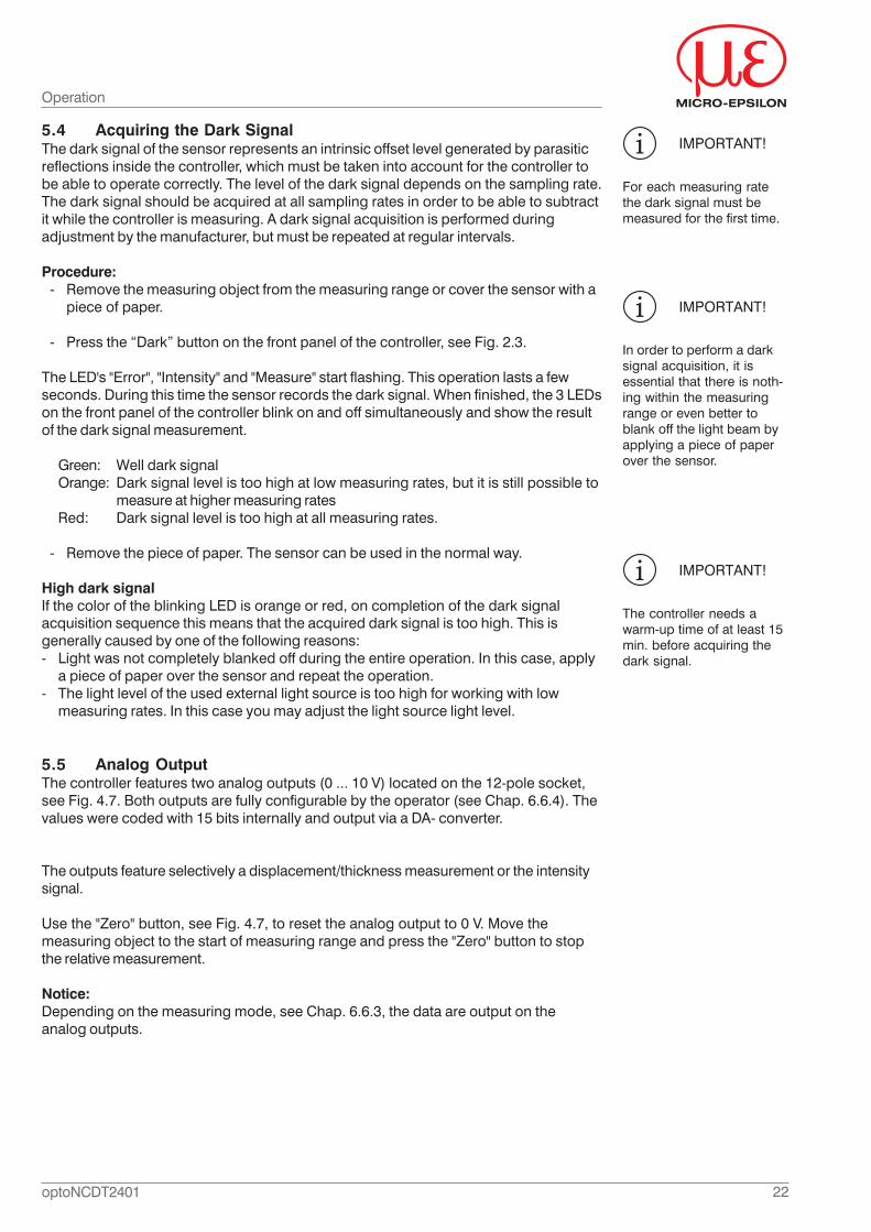
5.3 Thickness MeasurementIn the thickness measuring mode the sensor analyzes two signals reflected from the twosurfaces of a transparent measuring object. The controller calculates the intensity anddisplacement of surface 1 (front face, i.e. the nearest face), the displacement andintensity of surface 2 (rear face), and the thickness.
Align the sensor perpendicularly to the object to be measured. Make sure that themeasuring object is in midrange (= SMR + 0.5 * MR). As soon as the first surface(displacement 1) is in the measuring range of the sensor the LED "Measure", see Fig.2.3, on the front panel of the controller indicates it.The LED gives no advice about theattendance of the second surface in the measurement range of the sensor.
Minimum measurable thickness of material: 8 % of sensor measuring rangeMaximum measurable thickness of material: sensor measuring range x materialrefrective index of measurement material
For the calculation of a correct thickness value the controller needs the refractive indexof the measuring object. To allow for the spectral variation of the refractive index in themeasuring range the controller features refractive index files.The file contains the chan-ging of the refrective index of a known measurement material inside the measuringrange.
Operation
SMR =Start of measuring range
MB =Measuring range
D 1/2 =Displacement 1/2
IMPORTANT!
The light beam must bedirected perpendicular ontothe surface of the target toavoid measuring errors.Please refer to the technicaldata for the maximum tiltbetween sensor andmeasuring object.
Fig. 5.1: One-sided thickness measurement against transparent materials
D 1
D 2
Thickness
SMR MR
IMPORTANT!
The controller uses the twostrongest peaks forthickness calculation.
If one surface is outside the measuring range the controller produces only a signal forthe displacement, intensity and barycenter. This can be although too, if a signal islocated below the threshold value. In the default setting (see chap.6.6.24), the controllertransmitts for the displacement 1 and the intensity 1 non-zero values.The other data items including thickness are set to zero.
22optoNCDT2401
IMPORTANT!
In order to perform a darksignal acquisition, it isessential that there is noth-ing within the measuringrange or even better toblank off the light beam byapplying a piece of paperover the sensor.
IMPORTANT!
The controller needs awarm-up time of at least 15min. before acquiring thedark signal.
5.4 Acquiring the Dark SignalThe dark signal of the sensor represents an intrinsic offset level generated by parasiticreflections inside the controller, which must be taken into account for the controller tobe able to operate correctly. The level of the dark signal depends on the sampling rate.The dark signal should be acquired at all sampling rates in order to be able to subtractit while the controller is measuring. A dark signal acquisition is performed duringadjustment by the manufacturer, but must be repeated at regular intervals.
Procedure:- Remove the measuring object from the measuring range or cover the sensor with a
piece of paper.
- Press the “Dark” button on the front panel of the controller, see Fig. 2.3.
The LED's "Error", "Intensity" and "Measure" start flashing. This operation lasts a fewseconds. During this time the sensor records the dark signal. When finished, the 3 LEDson the front panel of the controller blink on and off simultaneously and show the resultof the dark signal measurement.
Green: Well dark signalOrange: Dark signal level is too high at low measuring rates, but it is still possible to
measure at higher measuring ratesRed: Dark signal level is too high at all measuring rates.
- Remove the piece of paper. The sensor can be used in the normal way.
High dark signalIf the color of the blinking LED is orange or red, on completion of the dark signalacquisition sequence this means that the acquired dark signal is too high. This isgenerally caused by one of the following reasons:- Light was not completely blanked off during the entire operation. In this case, apply
a piece of paper over the sensor and repeat the operation.- The light level of the used external light source is too high for working with low
measuring rates. In this case you may adjust the light source light level.
5.5 Analog OutputThe controller features two analog outputs (0 ... 10 V) located on the 12-pole socket,see Fig. 4.7. Both outputs are fully configurable by the operator (see Chap. 6.6.4). Thevalues were coded with 15 bits internally and output via a DA- converter.
The outputs feature selectively a displacement/thickness measurement or the intensitysignal.
Use the "Zero" button, see Fig. 4.7, to reset the analog output to 0 V. Move themeasuring object to the start of measuring range and press the "Zero" button to stopthe relative measurement.
Notice:Depending on the measuring mode, see Chap. 6.6.3, the data are output on theanalog outputs.
Operation
IMPORTANT!
For each measuring ratethe dark signal must bemeasured for the first time.
23optoNCDT2401
5.6 Adjustment of the LED BrightnessIf your sensor is equipped with an external light source, please skip this chapter.
The LED brightness may be adjusted by "$LED" command, see Chap. 6.6.8. Place apiece of white paper in front of the sensor and observe the spot of light emitted bythe sensor.
Move the paper forward and backward to find the focus plane where the spotbrightness is maximal. Use the "$LED0" command to disappear the light spot.
The controller features an operation mode (“auto adaptive LED” mode) in which theLED brightness is automatically adjusted to the signal level. This mode is described inChap. 6.6.17.
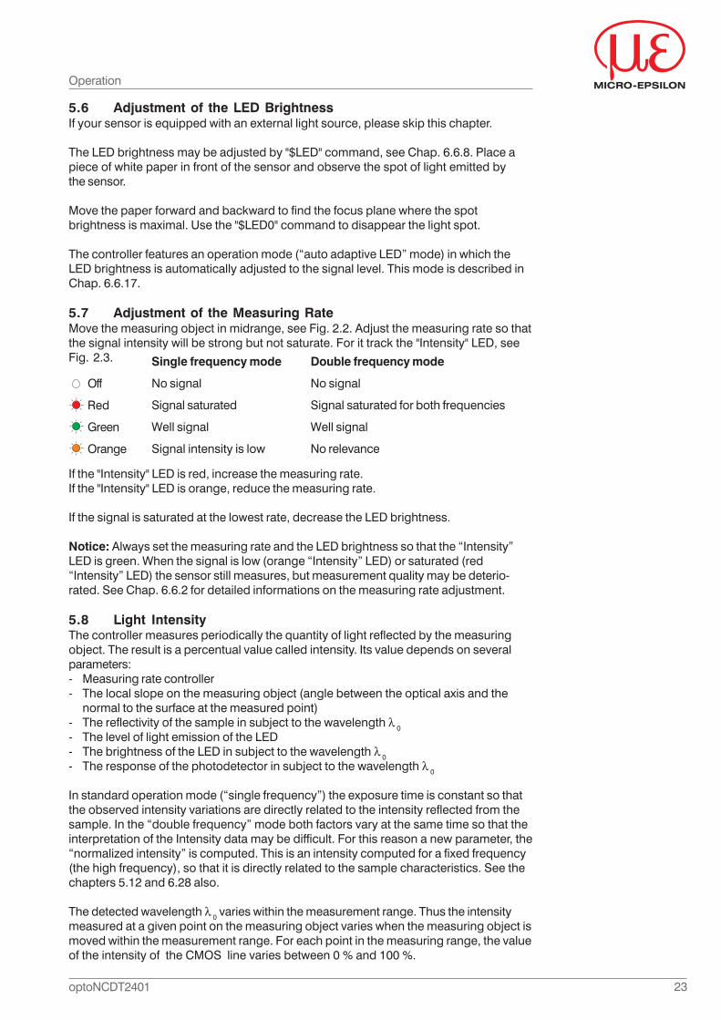
5.7 Adjustment of the Measuring RateMove the measuring object in midrange, see Fig. 2.2. Adjust the measuring rate so thatthe signal intensity will be strong but not saturate. For it track the "Intensity" LED, seeFig. 2.3.
If the "Intensity" LED is red, increase the measuring rate.If the "Intensity" LED is orange, reduce the measuring rate.
If the signal is saturated at the lowest rate, decrease the LED brightness.
Notice: Always set the measuring rate and the LED brightness so that the “Intensity”LED is green. When the signal is low (orange “Intensity” LED) or saturated (red“Intensity” LED) the sensor still measures, but measurement quality may be deterio-rated. See Chap. 6.6.2 for detailed informations on the measuring rate adjustment.
5.8 Light IntensityThe controller measures periodically the quantity of light reflected by the measuringobject. The result is a percentual value called intensity. Its value depends on severalparameters:- Measuring rate controller- The local slope on the measuring object (angle between the optical axis and the
normal to the surface at the measured point)- The reflectivity of the sample in subject to the wavelength 0- The level of light emission of the LED- The brightness of the LED in subject to the wavelength 0- The response of the photodetector in subject to the wavelength 0
In standard operation mode (“single frequency”) the exposure time is constant so thatthe observed intensity variations are directly related to the intensity reflected from thesample. In the “double frequency” mode both factors vary at the same time so that theinterpretation of the Intensity data may be difficult. For this reason a new parameter, the“normalized intensity” is computed. This is an intensity computed for a fixed frequency(the high frequency), so that it is directly related to the sample characteristics. See thechapters 5.12 and 6.28 also.
The detected wavelength 0 varies within the measurement range. Thus the intensitymeasured at a given point on the measuring object varies when the measuring object ismoved within the measurement range. For each point in the measuring range, the valueof the intensity of the CMOS line varies between 0 % and 100 %.
Operation
Off
Red
Green
Orange
Single frequency mode
No signal
Signal saturated
Well signal
Signal intensity is low
Double frequency mode
No signal
Signal saturated for both frequencies
Well signal
No relevance
24optoNCDT2401
Operation
Summary- Measurement quality is good when the “Intensity“ LED is green.- If the LED color is red, increase the measuring rate or lower the LED brightness.- If the LED color is orange, lower the measuring rate or increase the LED brightness.
5.9 Synchronized Controller and Encoder DataSynchronization signals and trigger modes are not required for synchronizing thecontroller with digital encoder readings: This task is performed automatically by thecontroller.
All you need to do is• Connect the encoders to the “Digital I/O" connector on the front panel as described
in Chap. 4.4.6• Reset each encoder counter by positioning it at the origin point of the motion range
and sending the “Reset Encoder Counter” (“$RCD”) command, see Chap. 6.6.22.• Configure the controller to transmit encoder data as well as data measured by the
controller, see Chap. 6.4.
5.10 TriggeringThe optoNCDT2401 measurement output is controllable through an external triggersignal (electrical signal in conjunction with a command). Thereby the anaog and digitaloutput is affected. Triggering does not influence the preset measuring rate. Thesynchronization input, see Fig. 4.8, is used for external triggering. By default, all triggermodes are disabled and the controller transmits data without interruption immediatelyafter startup.
5.10.1 Trigger ModesThe measurement output in trigger mode can be controlled with the flange as well asthe level of the trigger signal. Implemented trigger conditions:- Rising edge,- Falling edge,- High level or- Low level.
Set the trigger conditions (edge or level) with the "$TRF" command (see Chap. 6.6.12).
5.10.2 Trigger InputThe "Sync in" input, see Fig. 4.8, is used for triggering with an external signal (TTLcharacteristics). The duration of the "Sync in" pulses should be at least 1.2 μs.
Beyond that, the controller is saturated. Saturation is indicated by the "Intensity" LED(red, see Fig. 2.3). The saturation refers to the original signal of the CCD line.In the “Double Frequency” mode the “Intensity” LED indicator on the front panel iscorrelated to the high frequency.
25optoNCDT2401
Operation
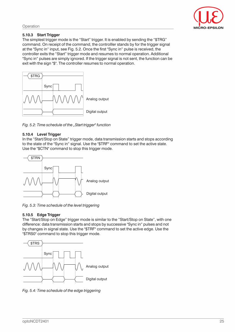
5.10.3 Start TriggerThe simplest trigger mode is the “Start” trigger. It is enabled by sending the “$TRG”command. On receipt of the command, the controlller stands by for the trigger signalat the "Sync in“ input, see Fig. 5.2. Once the first "Sync in“ pulse is received, thecontroller exits the “Start” trigger mode and resumes to normal operation. Additional"Sync in“ pulses are simply ignored. If the trigger signal is not sent, the function can beexit with the sign "$". The controller resumes to normal operation.
Fig. 5.2: Time schedule of the „Start trigger" function
5.10.4 Level TriggerIn the “Start/Stop on State” trigger mode, data transmission starts and stops accordingto the state of the "Sync in“ signal. Use the "$TRF" command to set the active state.Use the "$CTN" command to stop this trigger mode.
Fig. 5.3: Time schedule of the level triggering
5.10.5 Edge TriggerThe “Start/Stop on Edge” trigger mode is similar to the “Start/Stop on State”, with onedifference: data transmission starts and stops by successive "Sync in“ pulses and notby changes in signal state. Use the "$TRF" command to set the active edge. Use the"$TRS0" command to stop this trigger mode.
Fig. 5.4: Time schedule of the edge triggering
$TRG
Sync
Analog output
Digital output
$TRN
Sync
Analog output
Digital output
$TRS
Sync
Analog output
Digital output
26optoNCDT2401
Operation
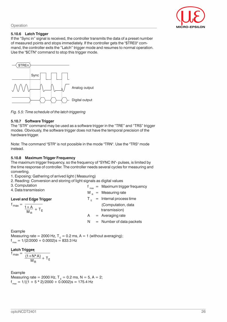
5.10.6 Latch TriggerIf the “Sync in” signal is received, the controller transmits the data of a preset numberof measured points and stops immediately. If the controller gets the "$TRE0" com-mand, the controller exits the “Latch” trigger mode and resumes to normal operation.Use the "$CTN" command to stop this trigger mode.
Fig. 5.5: Time schedule of the latch triggering
5.10.7 Software TriggerThe “STR” command may be used as a software trigger in the “TRE” and “TRS” triggermodes. Obviously, the software trigger does not have the temporal precision of thehardware trigger.
Note: The command "STR" is not poosible in the mode "TRN". Use the "TRS" modeinstead.
5.10.8 Maximum Trigger FrequencyThe maximum trigger frequency, so the frequency of "SYNC IN"- pulses, is limited bythe time response of controller. The controller needs several cycles for measuring andconverting.1. Exposing: Gathering of arrived light ( Measuring)2. Reading: Conversion and storing of light signals as digital values3. Computation4. Data transmission
Level and Edge Trigger
ExampleMeasuring rate = 2000 Hz, T E = 0.2 ms, A = 1 (without averaging);f max = 1/(2/2000 + 0.0002)s = 833.3 Hz
Latch Trigger
ExampleMeasuring rate = 2000 Hz, T E = 0.2 ms, N = 5, A = 2;f max = 1/((1 + 5 * 2)/2000 + 0.0002)s = 175.4 Hz
$TREn
Sync
Analog output
Digital output
f max = Maximum trigger frequency
M R = Measuring rate
T E = Internal process time
(Computation, data transmission)A = Averaging rate
N = Number of data packets
A
A
27optoNCDT2401
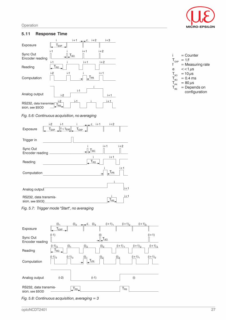
5.11 Response Time
i = CounterTEXP = 1/ff = Measuring ratee <<1 μsTSO = 10 μsTRO = 0.4 msTPR = 80 μsTRS = Depends on
configuration
Fig. 5.6: Continuous acquisition, no averaging
Fig. 5.7: Trigger mode "Start", no averaging
Fig. 5.8: Continuous acquisition, averaging = 3
Operation
TEXP
TRO
TPR
TRS
Exposure
Sync OutEncoder reading
Reading
Computation
Analog output
i-1 i i+1 i+2
i-1 i i+1i-2
i-1
i-2
TSO
i i+1i-1
i i+1 i+2 i+3
i+2
i
i+1
i-1 ii-2 i+1RS232, data transmis-s-sion, see $SOD
TEXP
TRO
TPR
TRS
Exposure
Reading
Computation
Analog output
i i+1
i i+1
TSO
i i+1
i-1 i i+1 i+2
i
i+1
i i+1
Trigger in
i+2
T TEXPTEXP
i-2
Sync OutEncoder reading
RS232, data transmis-sion, see $SOD
TEXP
TSO
TRO
TPR
TRS
Exposure
Sync OutEncoder reading
Reading
Computation
Analog output
(i-1)3 (i)1 (i)2 (i)3 (i+1)1 (i+1)2 (i+1)3
(i-1)3 (i)1 (i)2 (i)3(i-1)2 (i+1)2(i+1)1
(i-1) (i)(i-2)
TRS
(i) (i+1)(i-1)
(i)1 (i)2 (i)3 (i+1)1 (i+1)2 (i+1)3
RS232, data transmis-sion, see $SOD
28optoNCDT2401
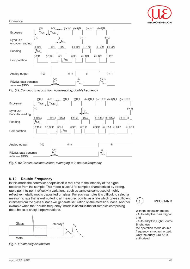
Fig. 5.9: Continuous acquisition, no averaging, double frequency
Fig. 5.10: Continuous acquisition, averaging = 2, double frequency
Operation
5.12 Double FrequencyIn this mode the controller adapts itself in real time to the intensity of the signalreceived from the sample. This mode is useful for samples characterized by strong,rapid point-to-point reflectivity variations, such as samples composed of highlyreflective metallic motifs deposited on glass. For such samples it is difficult to select ameasuring rate that is well suited to all measured points, as a rate which gives sufficientintensity from the glass surface will generate saturation on the metallic surface. Anotherexample when the “double frequency” mode is useful is that of samples comprisingdeep holes or sharp slope variations.
Intensity
Metal
Glass
Fig. 5.11: Intensity distribution
IMPORTANT!
With the operation modes- Auto-adaptive Dark Signal,and- Auto-adaptive Light SourceBrightnessthe operation mode doublefrequency is not authorized.Only the query "$DFA? isauthorized.
TEXP1
TSO
TRO
TPR
TRS
(i-1)f2 (i)f1 (i+1)f1
(i-1) (i)(i-2)
TRS
(i) (i+1)(i-1)
(i)f1 (i)f2 (i+1)f1
TEXP2
(i+1)f2 (i+2)f1 (i+2)f2
(i+2)
(i)f2 (i+1)f2 (i+2)f1 (i+2)f2
(i-1)f2 (i)f1 (i+1)f1(i)f2 (i+1)f2 (i+2)f1(i-1)f1
(i+1)
TRS
(i-1) (i) (i+1)
Exposure
Sync Outencoder reading
Reading
Computation
Analog output
RS232, data transmis-sion, see $SOD
TEXP1
TSO
TRO
TPR
TRS
(i-1)f2,2 (i)f1,1 (i)f1,2
(i-1) (i)(i-2)
(i)(i-1)
(i)f1,1 (i)f2,1
TEXP2
(i)f2,1 (i)f2,2 (i+1)f1,1 (i+1)f2,1
(i-1)f2,2 (i)f1,1 (i)f1,2(i)f2,1 (i)f2,2 (i+1)f1,1(i-1)f1,2
TRS
(i-1) (i)
(i)f1,2 (i)f2,2 (i+1)f1,2 (i+1)f2,2 (i+1)f1,2 (i+1)f2,2
(i+1)
(i+1)f1,2
(i+1)f2,1 (i+1)f1,2
Exposure
Sync OutEncoder reading
Reading
Computation
Analog output
RS232, data transmis-sion, see $SOD
29optoNCDT2401
Operation
In the “double frequency” mode the sensor switches permanently between 2frequencies- low frequency f1 (long exposure time) and- high frequency f2 (short exposure time).
It computes the data independently for each frequency, and then selects, for eachmeasured point, the optimal frequency.
The criteria for selecting the optimal frequency are resumed in the following table:
Case Low frequency High frequency Selected frequency1 Saturated Saturated high2 Saturated Correct measurement high3 Saturated No measurement low4 Correct measurement Correct measurement low5 Correct measurement No measurement low6 No measurement No measurement high
Example: Suppose that fL = 100 Hz (low frequency) and fH = 500 Hz (high frequency).On metallic surfaces the signal at 100 Hz is saturated and the signal at 500 Hz iscorrect. So the controller selects the high frequency (500 Hz). On glass substratemeasurements with 100 Hz are correct but with 500 Hz the signal is too low (nomeasurement). The controller selects the low frequency. Note that the high frequency islimited to 1850 Hz.
Each couple of acquisitions (one with long exposure and the other with short exposure)is called “a cycle”. The sensor delivers one “synchro out” signal per cycle. Measureddata are transmitted once per cycle on the digital outputs and updated once per cycleon the analog output.
The cycle rate fc is given by the relation: 1/fc = 1/f1 + 1/f2
IntensityThe intensity measured by the sensor depends, on one hand, on the characteristics ofthe sample like reflectivity, slope (see Chap. 5.8) and on the other, on the exposuretime. In standard operation mode (“single frequency”) the exposure time is constant sothat the observed intensity variations are directly related to the intensity of reflectedfrom the sample. In the “double frequency” mode both factors vary at the same time sothat the interpretation of the Intensity data may be difficult. For this reason a newparameter, the “normalized intensity” is computed. This is an intensity computedfor a fixed frequency (the high frequency), so that it is directly related to the samplecharacteristics.
Arrangement:- ILF is the intensity measured for the low frequency- IHF is the intensity measured for the high frequency
The following table shows the difference between the “raw” (standard) intensity and the“normalized” intensity.
Available intensities in « Double Frequency » mode
Selected Frequency « Raw » Intensity « Normalized » Intensity
Low (f1) ILF ILF * f1/f2
High (f2) IHF IHF
By default, the transmitted Intensity data is the “Normalized” one. This option may bemodified using the “DFI” command.
30optoNCDT2401
6. Serial InterfaceThe controller features two types of serial interfaces for controlling the controller andmeasurement output. The following chapter describes this possibilities for the RS232/RS422. The command language, the data transmission format are identical for the twotypes of serial interfaces.
When switched on, the controller transmits data according to the last configuration. Onreceipt of character "$" the controller stops sending data and waits for the remainingcommand characters. Each received character (including $) is echoed back. If thecommand includes parameters, the final "CR" character is echoed as well. When thecontroller receives a complete command and has completed the correspondingactions, it returns the string „ready CRLF“ and switches back to normal operation.
Received command is illegal:response is echo+ “invalid code<CRLF>“
Received command is legal put parameter values are illegal:response is echo + “not valid<CRLF>“.
Command and its parameters are legal but execution has failed:response is echo +””error<CRLF>“.
The "HyperTerminal®" program contains a user-friendly surface for serial communicationwith the controller, see Chap. 6.8.
Compatibility with other commands/modesThis mode is compatible with most other commands and modes, and in particular with- triggering,- averaging and- manual setting of the LED brightness.
It is not compatible with- auto-adaptive light source brightness, Chap. 6.6.17- auto-adaptive dark signal, Chap. 6.6.16- spectral averaging, Chap. 6.6.10- fast dark signal, Chap. 6.6.6.
Command Response when the controller is in “double frequency” mode
AAL, ADK, FDK, AVS Not authorizedDRK AuthorizedTRG, TRE, TRN, TRS, TRF AuthorizedAVR, HLV AuthorizedLED Authorized
FRQ, TEX, SRA
Authorized. Variables can be modified during double frequency mode. The controller operates with the new values, i f the controller quits the double frequency mode.
31optoNCDT2401
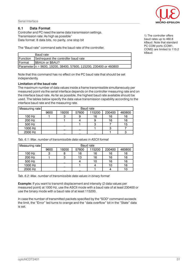
6.1 Data FormatController and PC need the same data transmission settings.Transmission rate: As high as possible 1
Data format: 8 data bits, no parity, one stop bit
The "Baud rate” command sets the baud rate of the controller.
Note that this command has no effect on the PC baud rate that should be setindependently.
Baud rateFunction Set/request the controller baud rateFormat $BAUn or $BAU?Parameter n = 9600, 19200, 38400, 57600, 115200, 230400 or 460800
Limitation of the baud rateThe maximum number of data values inside a frame transmissible simultaneously permeasured point via the serial interface depends on the controller measuring rate and onthe interface baud rate. As far as possible, the highest baud rate available should beused. The tables below specify the data value transmission capability according to theinterface baud rate and the measuring rate.
Tab. 6.1: Max. number of transmissible data values in ASCII format
Measuring rate9600 19200 57600 115200 230400 460800
100 Hz 1 3 9 16 16 16200 Hz _ 1 4 9 16 16500 Hz _ _ 1 3 7 15
1000 Hz _ _ _ 1 3 72000 Hz _ _ _ _ 1 3
Baud rate
Measuring rate9600 19200 57600 115200 230400 460800
100 Hz 3 8 16 16 16 16200 Hz 1 3 13 16 16 16500 Hz _ _ 4 10 16 16
1000 Hz _ _ 1 4 10 162000 Hz _ _ _ 1 4 10
Baud rate
Tab. 6.2: Max. number of transmissible data values in binary format
Example: If you want to transmit displacement and intensity (2 data values permeasured point) at 1000 Hz, use the ASCII mode with a baud rate of at least 230400 oruse the binary mode with a baud rate of at least 115200.
In case the number of transmitted packets specified by the "SOD" command exceedsthe limit, the “Error” led turns to orange and the “data overflow” bit in the “State” datais set.
1) The controller offersbaud rates up to 460.8kBaud. Note that standardPC COM ports (COM1,COM2) are limited to 115.2kBaud.
Serial Interface
32optoNCDT2401
X = digit (0 ... 9)
6.2 Command Syntax- Every command transmitted to the sensor must start by a "$" character.- Every command must end with a "<CRLF>" (carriage return, line feed) sequence.- Command name consists of 3 capital case letters.- When a command has one or more parameters, the parameters come immediately
after the command name.- There should be no comma between the name of the command and the first
parameter.- When a command includes several parameters, the parameters are separated by
commas.- For a query the parameter is replaced by “?”
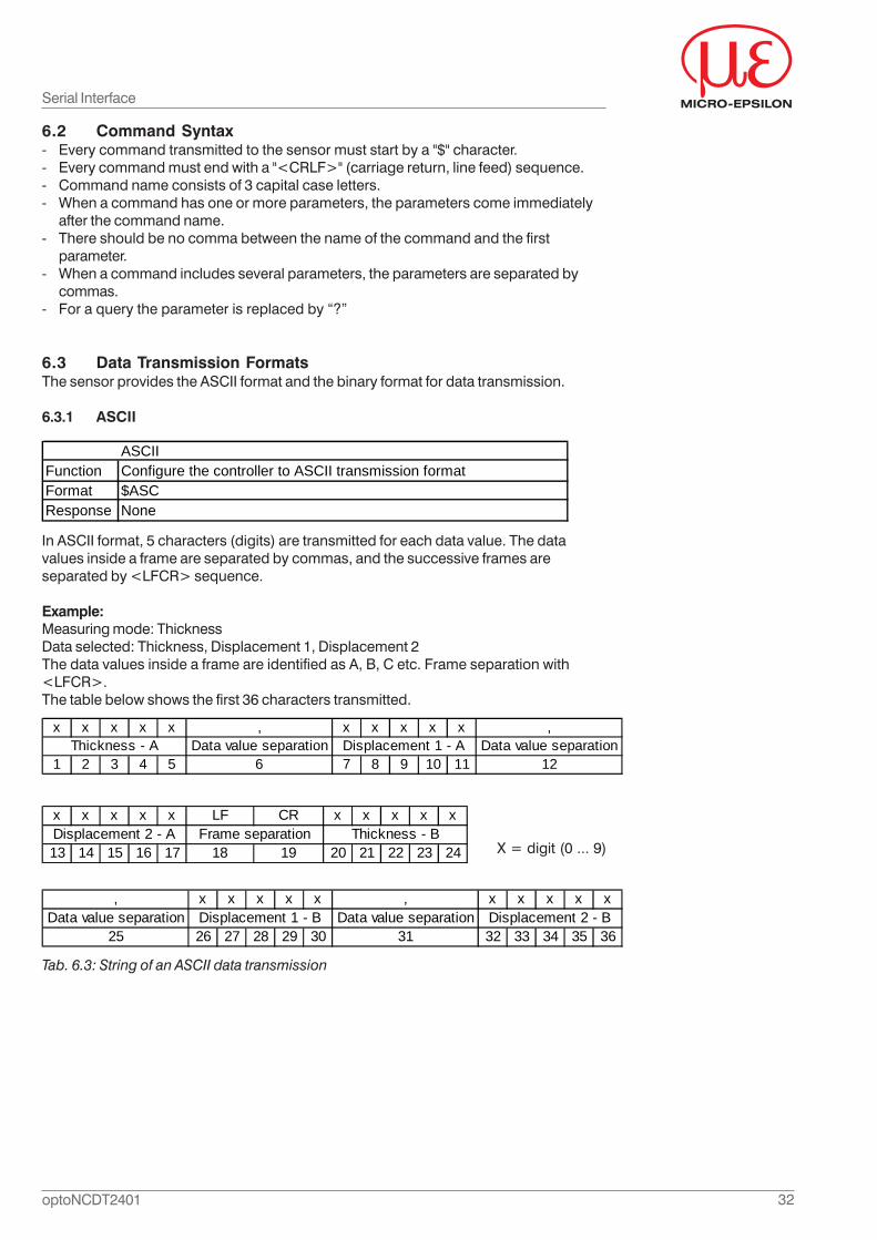
6.3 Data Transmission FormatsThe sensor provides the ASCII format and the binary format for data transmission.
6.3.1 ASCII
In ASCII format, 5 characters (digits) are transmitted for each data value. The datavalues inside a frame are separated by commas, and the successive frames areseparated by <LFCR> sequence.
Example:Measuring mode: ThicknessData selected: Thickness, Displacement 1, Displacement 2The data values inside a frame are identified as A, B, C etc. Frame separation with<LFCR>.The table below shows the first 36 characters transmitted.
Serial Interface
Tab. 6.3: String of an ASCII data transmission
x x x x x , x x x x x ,Data value separation Data value separation
1 2 3 4 5 6 7 8 9 10 11 12Thickness - A Displacement 1 - A
, x x x x x , x x x x xData value separation Data value separation
25 26 27 28 29 30 31 32 33 34 35 36Displacement 1 - B Displacement 2 - B
ASCIIFunction Configure the controller to ASCII transmission formatFormat $ASCResponse None
x x x x x LF CR x x x x x
13 14 15 16 17 18 19 20 21 22 23 24Displacement 2 - A Frame separation Thickness - B
33optoNCDT2401
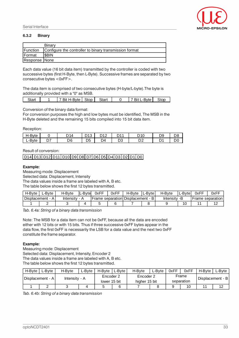
6.3.2 Binary
Each data value (16 bit data item) transmitted by the controller is coded with twosuccessive bytes (first H-Byte, then L-Byte). Successive frames are separated by twoconsecutive bytes <0xFF>.
The data item is comprised of two consecutive bytes (H-byte/L-byte).The byte isadditionally provided with a "0" as MSB.
Start 1 7 Bit H-Byte Stop Start 0 7 Bit L-Byte Stop
Conversion of the binary data format:For conversion purposes the high and low bytes must be identified, The MSB in theH-Byte deleted and the remaining 15 bits compiled into 15 bit data item.
Reception:
H-Byte 0 D14 D13 D12 D11 D10 D9 D8L-Byte D7 D6 D5 D4 D3 D2 D1 D0
Result of conversion:
D14 D13 D12 D11 D10 D9 D8 D7 D6 D5 D4 D3 D2 D1 D0
Example:Measuring mode: DisplacementSelected data: Displacement, IntensityThe data values inside a frame are labeled with A, B etc.The table below shows the first 12 bytes transmitted.
Tab. 6.4a: String of a binary data transmission
Note: The MSB for a data item can not be 0xFF, because all the data are encodedeither with 12 bits or with 15 bits. Thus if three successive 0xFF bytes appear in thedata flow, the first 0xFF is necessarily the LSB for a data value and the next two 0xFFconstitute the frame separator.
Example:Measuring mode: DisplacementSelected data: Displacement, Intensity, Encoder 2The data values inside a frame are labeled with A, B etc.The table below shows the first 12 bytes transmitted.
H-Byte L-Byte H-Byte L-Byte H-Byte L-Byte H-Byte L-Byte 0xFF 0xFF H-Byte L-Byte
1 2 3 4 5 6 7 8 9 10 11 12
Displacement - A Intensity - A Encoder 2lower 15 bit
Encoder 2higher 15 bit
Frame separation
Displacement - B
Tab. 6.4b: String of a binary data transmission
Serial Interface
BinaryFunction Configure the controller to binary transmission formatFormat $BINResponse None
H-Byte L-Byte H-Byte L-Byte 0xFF 0xFF H-Byte L-Byte H-Byte L-Byte 0xFF 0xFF
1 2 3 4 5 6 7 8 9 10 11 12Intensity -B Frame separationFrame separationDisplacement - A Intensity - A Displacement - B
34optoNCDT2401
D
D = DisplacementSMR = Start of measuring rangeMR = Measuring range
SMR MR
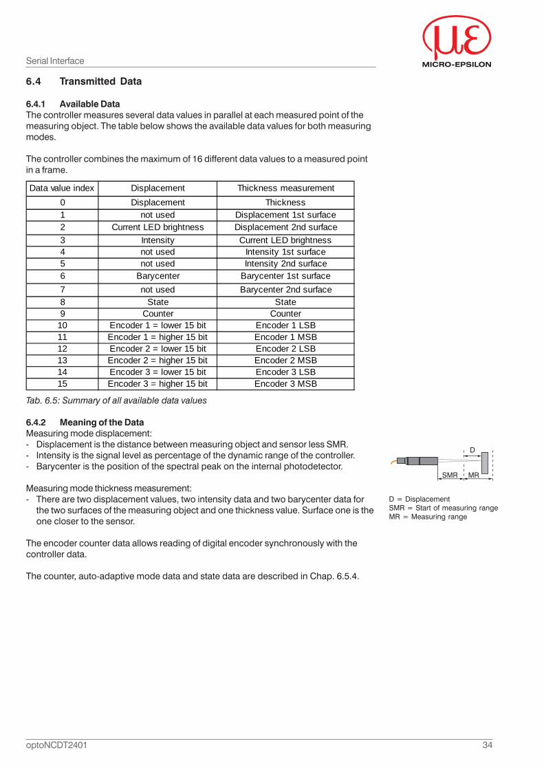
6.4 Transmitted Data
6.4.1 Available DataThe controller measures several data values in parallel at each measured point of themeasuring object. The table below shows the available data values for both measuringmodes.
The controller combines the maximum of 16 different data values to a measured pointin a frame.
Tab. 6.5: Summary of all available data values
6.4.2 Meaning of the DataMeasuring mode displacement:- Displacement is the distance between measuring object and sensor less SMR.- Intensity is the signal level as percentage of the dynamic range of the controller.- Barycenter is the position of the spectral peak on the internal photodetector.
Measuring mode thickness measurement:- There are two displacement values, two intensity data and two barycenter data for
the two surfaces of the measuring object and one thickness value. Surface one is theone closer to the sensor.
The encoder counter data allows reading of digital encoder synchronously with thecontroller data.
The counter, auto-adaptive mode data and state data are described in Chap. 6.5.4.
Data value index Displacement Thickness measurement0 Displacement Thickness1 not used Displacement 1st surface2 Current LED brightness Displacement 2nd surface3 Intensity Current LED brightness4 not used Intensity 1st surface5 not used Intensity 2nd surface6 Barycenter Barycenter 1st surface7 not used Barycenter 2nd surface8 State State9 Counter Counter
10 Encoder 1 = lower 15 bit Encoder 1 LSB11 Encoder 1 = higher 15 bit Encoder 1 MSB12 Encoder 2 = lower 15 bit Encoder 2 LSB13 Encoder 2 = higher 15 bit Encoder 2 MSB14 Encoder 3 = lower 15 bit Encoder 3 LSB15 Encoder 3 = higher 15 bit Encoder 3 MSB
Serial Interface
35optoNCDT2401
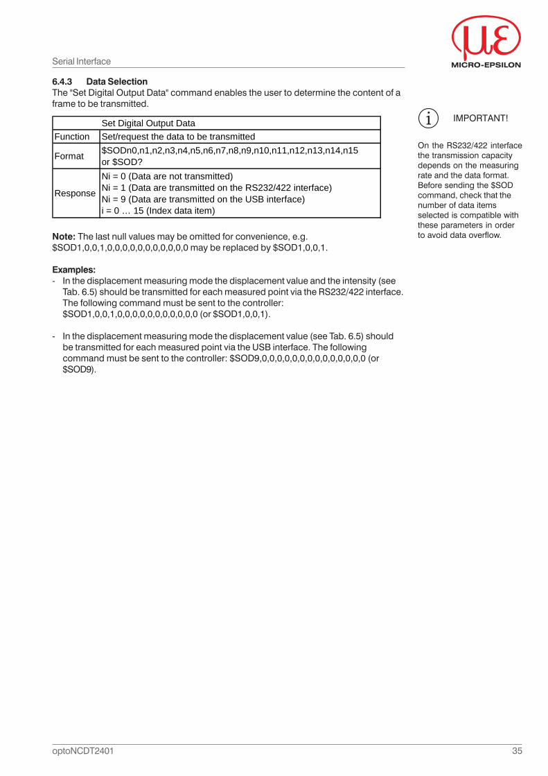
6.4.3 Data SelectionThe "Set Digital Output Data" command enables the user to determine the content of aframe to be transmitted.
Note: The last null values may be omitted for convenience, e.g.$SOD1,0,0,1,0,0,0,0,0,0,0,0,0,0,0 may be replaced by $SOD1,0,0,1.
Examples:- In the displacement measuring mode the displacement value and the intensity (see
Tab. 6.5) should be transmitted for each measured point via the RS232/422 interface.The following command must be sent to the controller:$SOD1,0,0,1,0,0,0,0,0,0,0,0,0,0,0 (or $SOD1,0,0,1).
- In the displacement measuring mode the displacement value (see Tab. 6.5) shouldbe transmitted for each measured point via the USB interface. The followingcommand must be sent to the controller: $SOD9,0,0,0,0,0,0,0,0,0,0,0,0,0,0 (or$SOD9).
IMPORTANT!
On the RS232/422 interfacethe transmission capacitydepends on the measuringrate and the data format.Before sending the $SODcommand, check that thenumber of data itemsselected is compatible withthese parameters in orderto avoid data overflow.
Serial Interface
Set Digital Output DataFunction Set/request the data to be transmitted
Format $SODn0,n1,n2,n3,n4,n5,n6,n7,n8,n9,n10,n11,n12,n13,n14,n15 or $SOD?
Response
Ni = 0 (Data are not transmitted)Ni = 1 (Data are transmitted on the RS232/422 interface)Ni = 9 (Data are transmitted on the USB interface)i = 0 … 15 (Index data item)
36optoNCDT2401
Serial Interface
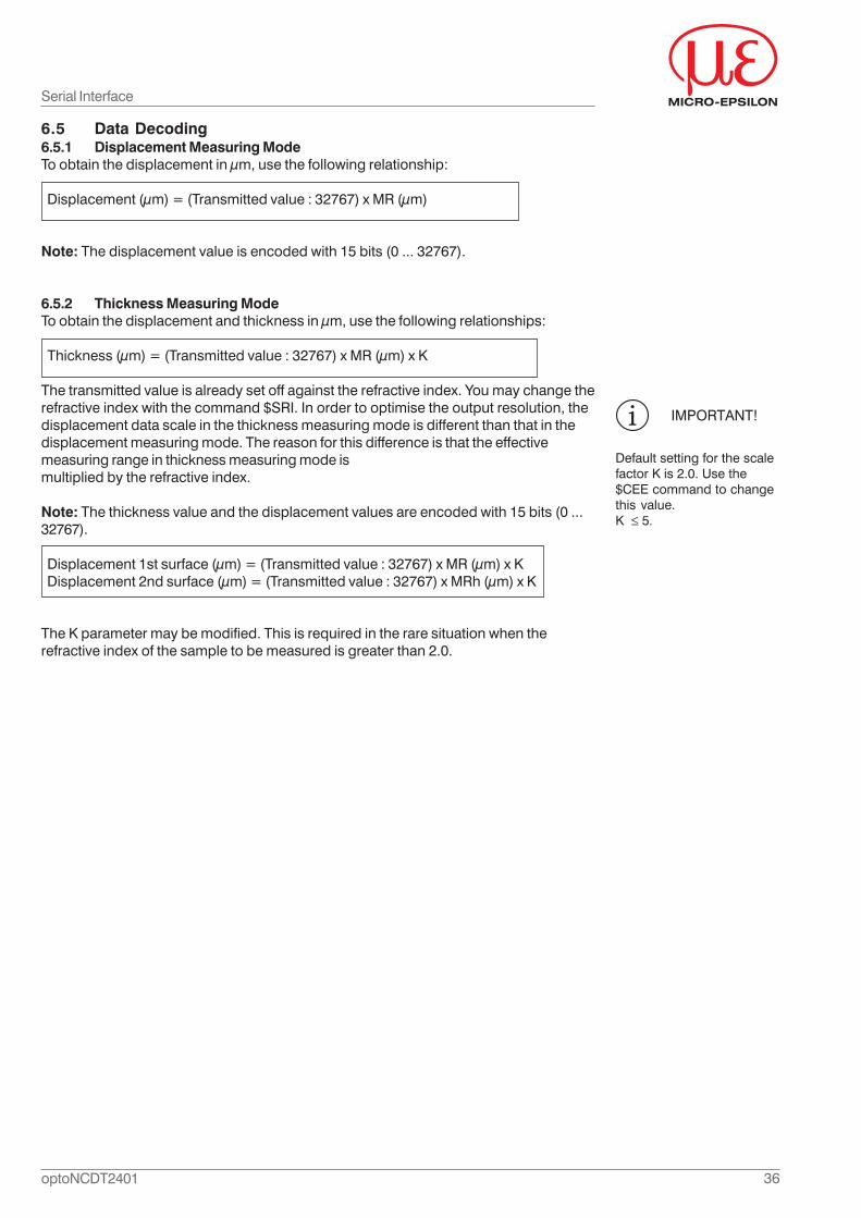
6.5 Data Decoding6.5.1 Displacement Measuring ModeTo obtain the displacement in μm, use the following relationship:
Displacement (μm) = (Transmitted value : 32767) x MR (μm)
Note: The displacement value is encoded with 15 bits (0 ... 32767).
6.5.2 Thickness Measuring ModeTo obtain the displacement and thickness in μm, use the following relationships:
Thickness (μm) = (Transmitted value : 32767) x MR (μm) x K
The transmitted value is already set off against the refractive index. You may change therefractive index with the command $SRI. In order to optimise the output resolution, thedisplacement data scale in the thickness measuring mode is different than that in thedisplacement measuring mode. The reason for this difference is that the effectivemeasuring range in thickness measuring mode ismultiplied by the refractive index.
Note: The thickness value and the displacement values are encoded with 15 bits (0 ...32767).
Displacement 1st surface (μm) = (Transmitted value : 32767) x MR (μm) x K Displacement 2nd surface (μm) = (Transmitted value : 32767) x MRh (μm) x K
The K parameter may be modified. This is required in the rare situation when therefractive index of the sample to be measured is greater than 2.0.
IMPORTANT!
Default setting for the scalefactor K is 2.0. Use the$CEE command to changethis value.K ≤ 5.
37optoNCDT2401
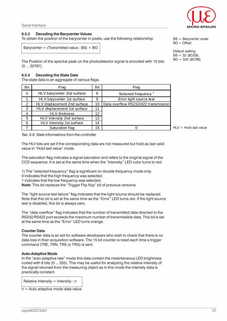
6.5.3 Decoding the Barycenter ValuesTo obtain the position of the barycenter in pixels, use the following relationship:
Barycenter = (Transmitted value : BS) + BO
The Position of the spectral peak on the photodetector signal is encoded with 15 bits(0 ... 32767).
6.5.4 Decoding the State DataThe state data is an aggregate of various flags.
Tab. 6.6: State informations from the controller
The HLV bits are set if the corresponding data are not measured but hold as last validvalue in “Hold last value” mode.
The saturation flag indicates a signal saturation and refers to the original signal of theCCD sequence. It is set at the same time when the “Intensity” LED color turns to red.
1) The “selected frequency” flag is significant on double-frequency mode only.0 indicates that the high frequency was selected,1 indicates that the low frequency was selected.Note: This bit replaces the “Trigger Flip-flop” bit of previous versions.
The “light source test failure” flag indicates that the light source should be replaced.Note that this bit is set at the same time as the “Error” LED turns red. If the light sourcetest is disabled, this bit is always zero.
The “data overflow” flag indicates that the number of transmitted data directed to theRS232/RS422 port exceeds the maximum number of transmissible data. This bit is setat the same time as the “Error” LED turns orange.
Counter DataThe counter data is an aid for software developers who wish to check that there is nodata loss in their acquisition software. The 15 bit counter is reset each time a triggercommand (TRE, TRN, TRS or TRG) is sent.
Auto-Adaptive ModeIn the “auto-adaptive rate” mode this data contain the instantaneous LED brightnesscoded with 8 bits (0 ... 255). This may be useful for analyzing the relative intensity ofthe signal returned from the measuring object as in this mode the intensity data ispractically constant.
Relative Intensity = Intensity : n
BS = Barycenter scaleBO = Offset
Default setting:BS = 32 ($CEB),BO = 520 ($CRB)
n = Auto adaptive mode data value
Serial Interface
HLV = Hold last value
Bit Flag Bit Flag0 HLV barycenter 2nd surface 8 Selected frequency 1
1 HLV barycenter 1st surface 9 Error light source test2 HLV displacement 2nd surface 10 Data overflow RS232/422 transmission3 HLV displacement 1st surface 114 HLV thickness 125 HLV Intensity 2nd surface 136 HLV Intensity 1st surface 147 Saturation f lag 15 0
38optoNCDT2401
6.6 Commands
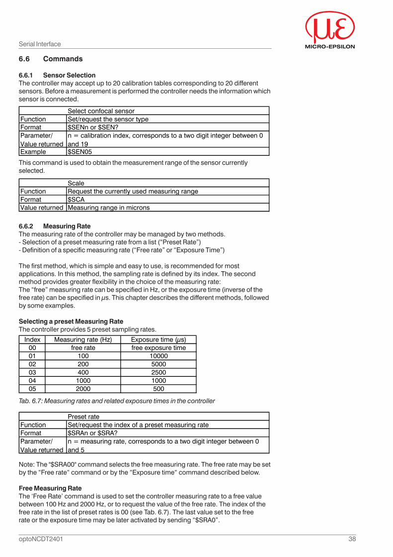
6.6.1 Sensor SelectionThe controller may accept up to 20 calibration tables corresponding to 20 differentsensors. Before a measurement is performed the controller needs the information whichsensor is connected.
This command is used to obtain the measurement range of the sensor currentlyselected.
6.6.2 Measuring RateThe measuring rate of the controller may be managed by two methods.- Selection of a preset measuring rate from a list (“Preset Rate”)- Definition of a specific measuring rate (“Free rate” or “Exposure Time”)
The first method, which is simple and easy to use, is recommended for mostapplications. In this method, the sampling rate is defined by its index. The secondmethod provides greater flexibility in the choice of the measuring rate:The “free” measuring rate can be specified in Hz, or the exposure time (inverse of thefree rate) can be specified in μs. This chapter describes the different methods, followedby some examples.
Selecting a preset Measuring RateThe controller provides 5 preset sampling rates.
Tab. 6.7: Measuring rates and related exposure times in the controller
Note: The "$SRA00" command selects the free measuring rate. The free rate may be setby the “Free rate“ command or by the “Exposure time“ command described below.
Free Measuring RateThe ‘Free Rate’ command is used to set the controller measuring rate to a free valuebetween 100 Hz and 2000 Hz, or to request the value of the free rate. The index of thefree rate in the list of preset rates is 00 (see Tab. 6.7). The last value set to the freerate or the exposure time may be later activated by sending “$SRA0”.
Serial Interface
ScaleFunction Request the currently used measuring rangeFormat $SCAValue returned Measuring range in microns
Index Measuring rate (Hz) Exposure time (μs)00 free rate free exposure time01 100 1000002 200 500003 400 250004 1000 100005 2000 500
Select confocal sensorFunction Set/request the sensor typeFormat $SENn or $SEN?Parameter/Value returned
n = calibration index, corresponds to a two digit integer between 0 and 19
Example $SEN05
Preset rateFunction Set/request the index of a preset measuring rateFormat $SRAn or $SRA?Parameter/Value returned
n = measuring rate, corresponds to a two digit integer between 0 and 5
39optoNCDT2401
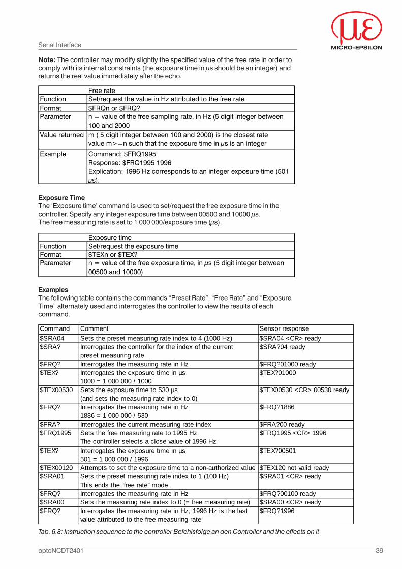
ExamplesThe following table contains the commands “Preset Rate”, “Free Rate” and “ExposureTime” alternately used and interrogates the controller to view the results of eachcommand.
Note: The controller may modify slightly the specified value of the free rate in order tocomply with its internal constraints (the exposure time in μs should be an integer) andreturns the real value immediately after the echo.
Exposure TimeThe ‘Exposure time’ command is used to set/request the free exposure time in thecontroller. Specify any integer exposure time between 00500 and 10000 μs.The free measuring rate is set to 1 000 000/exposure time (μs).
Serial Interface
Tab. 6.8: Instruction sequence to the controller Befehlsfolge an den Controller and the effects on it
Free rateFunction Set/request the value in Hz attributed to the free rateFormat $FRQn or $FRQ?Parameter n = value of the free sampling rate, in Hz (5 digit integer between
100 and 2000Value returned m ( 5 digit integer between 100 and 2000) is the closest rate
value m>=n such that the exposure time in μs is an integer
Example Command: $FRQ1995 Response: $FRQ1995 1996 Explication: 1996 Hz corresponds to an integer exposure time (501 μs).
Exposure timeFunction Set/request the exposure timeFormat $TEXn or $TEX?Parameter n = value of the free exposure time, in μs (5 digit integer between
00500 and 10000)
Command Comment Sensor response$SRA04 Sets the preset measuring rate index to 4 (1000 Hz) $SRA04 <CR> ready$SRA? Interrogates the controller for the index of the current
preset measuring rate$SRA?04 ready
$FRQ? Interrogates the measuring rate in Hz $FRQ?01000 ready$TEX? Interrogates the exposure time in µs
1000 = 1 000 000 / 1000$TEX?01000
$TEX00530 Sets the exposure time to 530 µs (and sets the measuring rate index to 0)
$TEX00530 <CR> 00530 ready
$FRQ? Interrogates the measuring rate in Hz1886 = 1 000 000 / 530
$FRQ?1886
$FRA? Interrogates the current measuring rate index $FRA?00 ready$FRQ1995 Sets the free measuring rate to 1995 Hz
The controller selects a close value of 1996 Hz$FRQ1995 <CR> 1996
$TEX? Interrogates the exposure time in µs501 = 1 000 000 / 1996
$TEX?00501
$TEX00120 Attempts to set the exposure time to a non-authorized value $TEX120 not valid ready$SRA01 Sets the preset measuring rate index to 1 (100 Hz)
This ends the “free rate” mode$SRA01 <CR> ready
$FRQ? Interrogates the measuring rate in Hz $FRQ?00100 ready$SRA00 Sets the measuring rate index to 0 (= free measuring rate) $SRA00 <CR> ready$FRQ? Interrogates the measuring rate in Hz, 1996 Hz is the last
value attributed to the free measuring rate$FRQ?1996
40optoNCDT2401
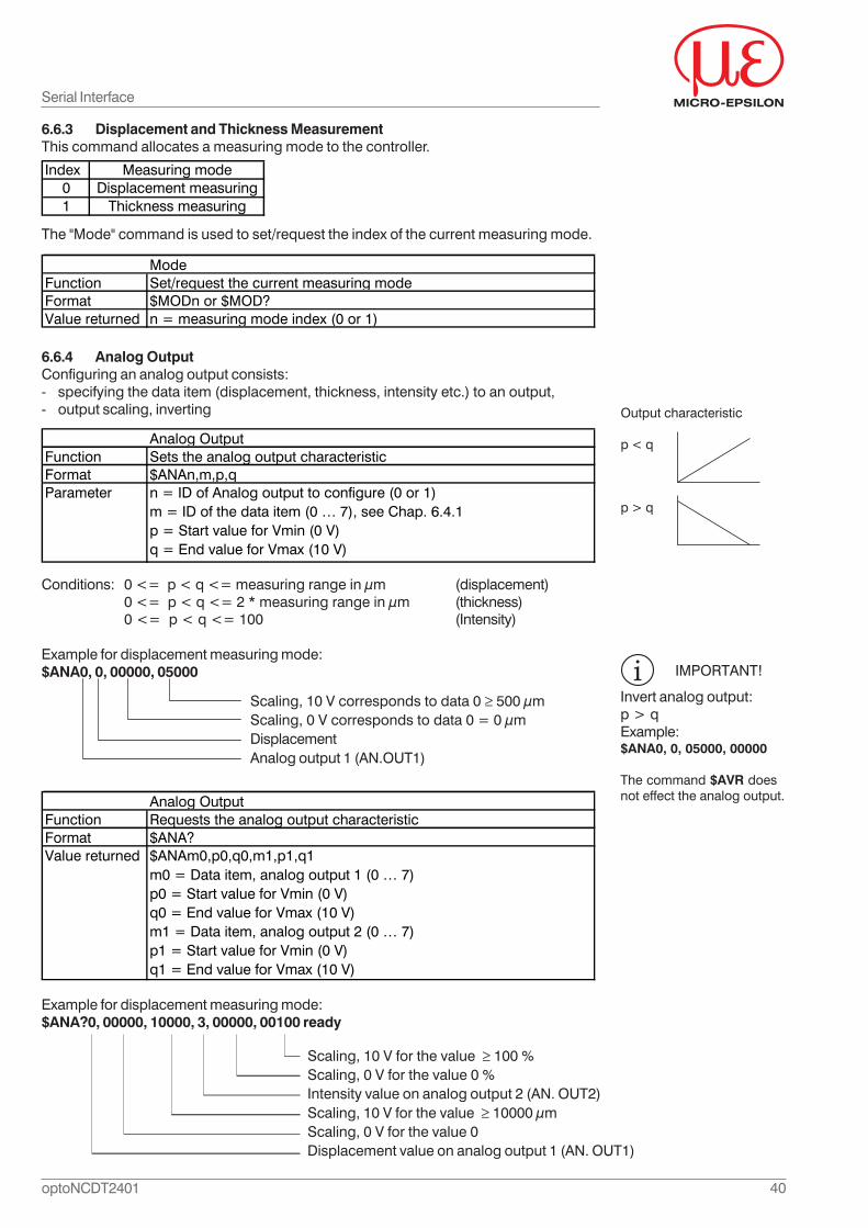
6.6.3 Displacement and Thickness MeasurementThis command allocates a measuring mode to the controller.
The "Mode" command is used to set/request the index of the current measuring mode.
6.6.4 Analog OutputConfiguring an analog output consists:- specifying the data item (displacement, thickness, intensity etc.) to an output,- output scaling, inverting
Conditions: 0 <= p < q <= measuring range in μm (displacement)0 <= p < q <= 2 * measuring range in μm (thickness)0 <= p < q <= 100 (Intensity)
Example for displacement measuring mode:$ANA0, 0, 00000, 05000
Example for displacement measuring mode:$ANA?0, 00000, 10000, 3, 00000, 00100 ready
Serial Interface
Scaling, 10 V corresponds to data 0 ≥ 500 μmScaling, 0 V corresponds to data 0 = 0 μmDisplacementAnalog output 1 (AN.OUT1)
Index Measuring mode0 Displacement measuring1 Thickness measuring
ModeFunction Set/request the current measuring modeFormat $MODn or $MOD?Value returned n = measuring mode index (0 or 1)
Analog OutputFunction Sets the analog output characteristic Format $ANAn,m,p,qParameter n = ID of Analog output to configure (0 or 1)
m = ID of the data item (0 … 7), see Chap. 6.4.1p = Start value for Vmin (0 V)q = End value for Vmax (10 V)
Analog OutputFunction Requests the analog output characteristic Format $ANA?Value returned $ANAm0,p0,q0,m1,p1,q1
m0 = Data item, analog output 1 (0 … 7)p0 = Start value for Vmin (0 V)q0 = End value for Vmax (10 V)m1 = Data item, analog output 2 (0 … 7)p1 = Start value for Vmin (0 V)q1 = End value for Vmax (10 V)
Scaling, 10 V for the value ≥ 100 %Scaling, 0 V for the value 0 %Intensity value on analog output 2 (AN. OUT2)Scaling, 10 V for the value ≥ 10000 μmScaling, 0 V for the value 0Displacement value on analog output 1 (AN. OUT1)
IMPORTANT!
Invert analog output:p > qExample:$ANA0, 0, 05000, 00000
The command $AVR doesnot effect the analog output.
Output characteristic
p < q
p > q
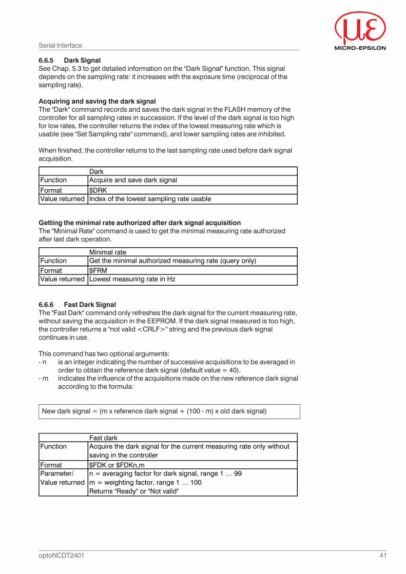
41optoNCDT2401
Getting the minimal rate authorized after dark signal acquisitionThe "Minimal Rate" command is used to get the minimal measuring rate authorizedafter last dark operation.
6.6.6 Fast Dark SignalThe "Fast Dark" command only refreshes the dark signal for the current measuring rate,without saving the acquisition in the EEPROM. If the dark signal measured is too high,the controller returns a "not valid <CRLF>" string and the previous dark signalcontinues in use.
This command has two optional arguments:- n is an integer indicating the number of successive acquisitions to be averaged in
order to obtain the reference dark signal (default value = 40).- m indicates the influence of the acquisitions made on the new reference dark signal
according to the formula:
New dark signal = (m x reference dark signal + (100 - m) x old dark signal)
6.6.5 Dark SignalSee Chap. 5.3 to get detailed information on the "Dark Signal" function. This signaldepends on the sampling rate: it increases with the exposure time (reciprocal of thesampling rate).
Acquiring and saving the dark signalThe "Dark" command records and saves the dark signal in the FLASH memory of thecontroller for all sampling rates in succession. If the level of the dark signal is too highfor low rates, the controller returns the index of the lowest measuring rate which isusable (see "Set Sampling rate" command), and lower sampling rates are inhibited.
When finished, the controller returns to the last sampling rate used before dark signalacquisition.
Serial Interface
DarkFunction Acquire and save dark signal
Format $DRKValue returned Index of the lowest sampling rate usable
Minimal rateFunction Get the minimal authorized measuring rate (query only)Format $FRMValue returned Lowest measuring rate in Hz
Fast darkFunction Acquire the dark signal for the current measuring rate only without
saving in the controller Format $FDK or $FDKn,mParameter/Value returned
n = averaging factor for dark signal, range 1 … 99m = weighting factor, range 1 … 100Returns "Ready" or "Not valid"
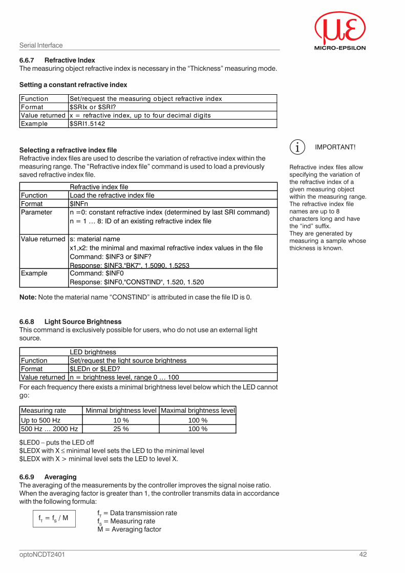
42optoNCDT2401
6.6.7 Refractive IndexThe measuring object refractive index is necessary in the “Thickness” measuring mode.
Setting a constant refractive index
Selecting a refractive index fileRefractive index files are used to describe the variation of refractive index within themeasuring range. The “Refractive index file” command is used to load a previouslysaved refractive index file.
Note: Note the material name “CONSTIND” is attributed in case the file ID is 0.
6.6.8 Light Source BrightnessThis command is exclusively possible for users, who do not use an external lightsource.
For each frequency there exists a minimal brightness level below which the LED cannotgo:
6.6.9 AveragingThe averaging of the measurements by the controller improves the signal noise ratio.When the averaging factor is greater than 1, the controller transmits data in accordancewith the following formula:
fT = fS / MfT = Data transmission ratefS = Measuring rateM = Averaging factor
IMPORTANT!
Refractive index files allowspecifying the variation ofthe refractive index of agiven measuring objectwithin the measuring range.The refractive index filenames are up to 8characters long and havethe “ind” suffix.They are generated bymeasuring a sample whosethickness is known.
Serial Interface
Function Set/request the measuring object refractive indexFormat $SRIx or $SRI?Value returned x = refractive index, up to four decimal digitsExample $SRI1.5142
LED brightnessFunction Set/request the light source brightnessFormat $LEDn or $LED?Value returned n = brightness level, range 0 … 100
Refractive index fileFunction Load the refractive index fileFormat $INFnParameter n =0: constant refractive index (determined by last SRI command)
n = 1 … 8: ID of an existing refractive index file
Value returned s: material namex1,x2: the minimal and maximal refractive index values in the fileCommand: $INF3 or $INF?Response: $INF3,"BK7", 1.5090, 1.5253
Example Command: $INF0Response: $INF0,"CONSTIND", 1.520, 1.520
Measuring rate Minmal brightness level Maximal brightness levelUp to 500 Hz 10 % 100 %500 Hz … 2000 Hz 25 % 100 %
$LED0 – puts the LED off$LEDX with X minimal level sets the LED to the minimal level$LEDX with X > minimal level sets the LED to level X.
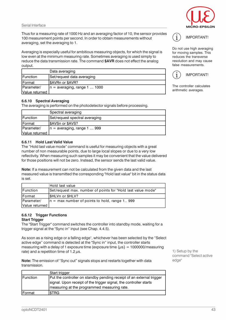
43optoNCDT2401
6.6.10 Spectral AveragingThe averaging is performed on the photodetector signals before processing.
6.6.11 Hold Last Valid ValueThe “Hold last value mode” command is useful for measuring objects with a greatnumber of non measurable points, due to large local slopes or due to a very lowreflectivity. When measuring such samples it may be convenient that the value deliveredfor those positions will not be zero. Instead, the sensor sends the last valid value.
Note: If a measurement can not be calculated from the given data and the lastmeasured value is transmitted the corresponding "Hold last value" bit in the status datais set.
6.6.12 Trigger FunctionsStart TriggerThe "Start Trigger" command switches the controller into standby mode, waiting for atrigger signal at the "Sync in“ input (see Chap. 4.4.5).
As soon as a rising edge or a falling edge1, whichever has been selected by the “Selectactive edge” command is detected at the "Sync in“ input, the controller startsmeasuring with a delay of 1 exposure time (exposure time {μs} = 1000000/measuringrate) and a repetition time of 1.2 μs.
Note: The emission of “Sync out” signals stops and restarts together with datatransmission.
IMPORTANT!
The controller calculatesarithmetic averages.
Serial Interface
Data averagingFunction Set/request data averaging
Format $AVRn or $AVR?Parameter/Value returned
n = averaging, range 1 … 1000
Spectral averagingFunction Set/request spectral averaging
Format $AVSn or $AVS?Parameter/Value returned
n = averaging, range 1 … 999
Hold last valueFunction Set/request max. number of points for "Hold last value mode"
Format $HLVn or $HLV?Parameter/Value returned
n = max number of points to hold, range 1.. 999
Start triggerFunction Put the controller on standby pending receipt of an external trigger
signal. Upon receipt of the trigger signal, the controller starts measuring at the programmed measuring rate.
Format $TRG
IMPORTANT!
Do not use high averagingfor moving samples. Thisreduces the transverseresolution and may causefalse measurements.
Thus for a measuring rate of 1000 Hz and an averaging factor of 10, the sensor provides100 measurement points per second. In order to obtain measurements withoutaveraging, set the averaging to 1.
Averaging is especially useful for ambitious measuring objects, for which the signal islow even at the minimum measuring rate. Sometimes averaging is used simply toreduce the data transmission rate. The command $AVR does not effect the analogoutput.
1) Setup by thecommand "Select activeedge"
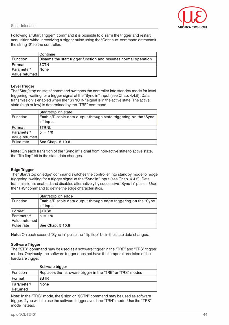
44optoNCDT2401
Following a "Start Trigger" command it is possible to disarm the trigger and restartacquisition without receiving a trigger pulse using the "Continue" command or transmitthe string "$" to the controller.
Level TriggerThe "Start/stop on state" command switches the controller into standby mode for leveltriggering, waiting for a trigger signal at the "Sync in“ input (see Chap. 4.4.5). Datatransmission is enabled when the “SYNC IN” signal is in the active state. The activestate (high or low) is determined by the “TRF” command.
Note: On each transition of the “Sync in” signal from non-active state to active state,the “flip flop” bit in the state data changes.
Edge TriggerThe "Start/stop on edge" command switches the controller into standby mode for edgetriggering, waiting for a trigger signal at the "Sync in“ input (see Chap. 4.4.5). Datatransmission is enabled and disabled alternatively by successive “Sync in” pulses. Usethe "TRS" command to define the edge characteristics.
Note: On each second “Sync in” pulse the “flip flop” bit in the state data changes.
Serial Interface
ContinueFunction Disarms the start trigger function and resumes normal operation
Format $CTNParameter/Value returned
None
Start/stop on edgeFunction Enable/Disable data output through edge triggering on the "Sync
In" inputFormat $TRSbParameter/Value returned
b = 1/0
Pulse rate See Chap. 5.10.8
Start/stop on stateFunction Enable/Disable data output through state triggering on the "Sync
In" input
Format $TRNbParameter/Value returned
b = 1/0
Pulse rate See Chap. 5.10.8
Software TriggerThe “STR” command may be used as a software trigger in the “TRE” and “TRS” triggermodes. Obviously, the software trigger does not have the temporal precision of thehardware trigger.
Software trigger
Function Replaces the hardware trigger in the "TRE" or "TRS" modes
Format $STR
Parameter/Returned
None
Note: In the “TRG” mode, the $ sign or “$CTN” command may be used as softwaretrigger. If you wish to use the software trigger avoid the “TRN” mode. Use the “TRS”mode instead.
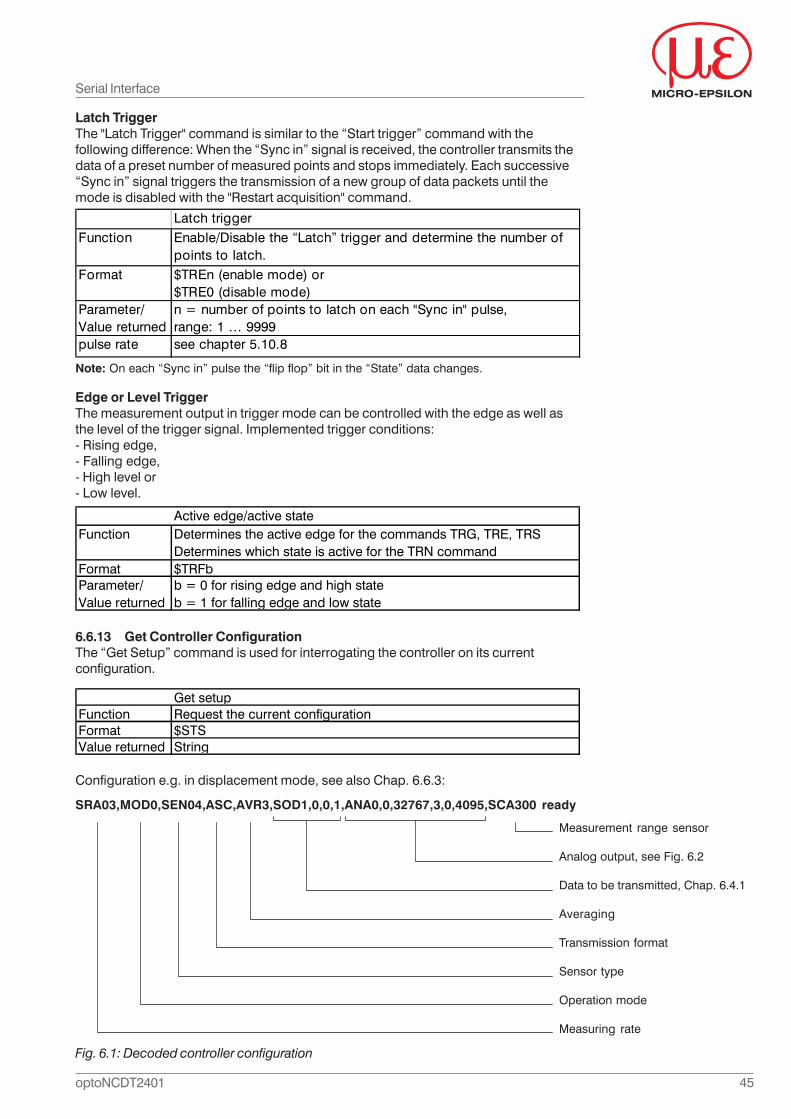
45optoNCDT2401
Edge or Level TriggerThe measurement output in trigger mode can be controlled with the edge as well asthe level of the trigger signal. Implemented trigger conditions:- Rising edge,- Falling edge,- High level or- Low level.
6.6.13 Get Controller ConfigurationThe “Get Setup” command is used for interrogating the controller on its currentconfiguration.
Configuration e.g. in displacement mode, see also Chap. 6.6.3:
SRA03,MOD0,SEN04,ASC,AVR3,SOD1,0,0,1,ANA0,0,32767,3,0,4095,SCA300 ready
Measurement range sensor
Analog output, see Fig. 6.2
Data to be transmitted, Chap. 6.4.1
Averaging
Transmission format
Sensor type
Operation mode
Measuring rate
Serial Interface
Active edge/active stateFunction Determines the active edge for the commands TRG, TRE, TRS
Determines which state is active for the TRN commandFormat $TRFbParameter/Value returned
b = 0 for rising edge and high stateb = 1 for falling edge and low state
Get setupFunction Request the current configurationFormat $STSValue returned String
Latch triggerFunction Enable/Disable the “Latch” trigger and determine the number of
points to latch.Format $TREn (enable mode) or
$TRE0 (disable mode)Parameter/Value returned
n = number of points to latch on each "Sync in" pulse, range: 1 … 9999
pulse rate see chapter 5.10.8
Note: On each “Sync in” pulse the “flip flop” bit in the “State” data changes.
Fig. 6.1: Decoded controller configuration
Latch TriggerThe "Latch Trigger" command is similar to the “Start trigger” command with thefollowing difference: When the “Sync in” signal is received, the controller transmits thedata of a preset number of measured points and stops immediately. Each successive“Sync in” signal triggers the transmission of a new group of data packets until themode is disabled with the "Restart acquisition" command.
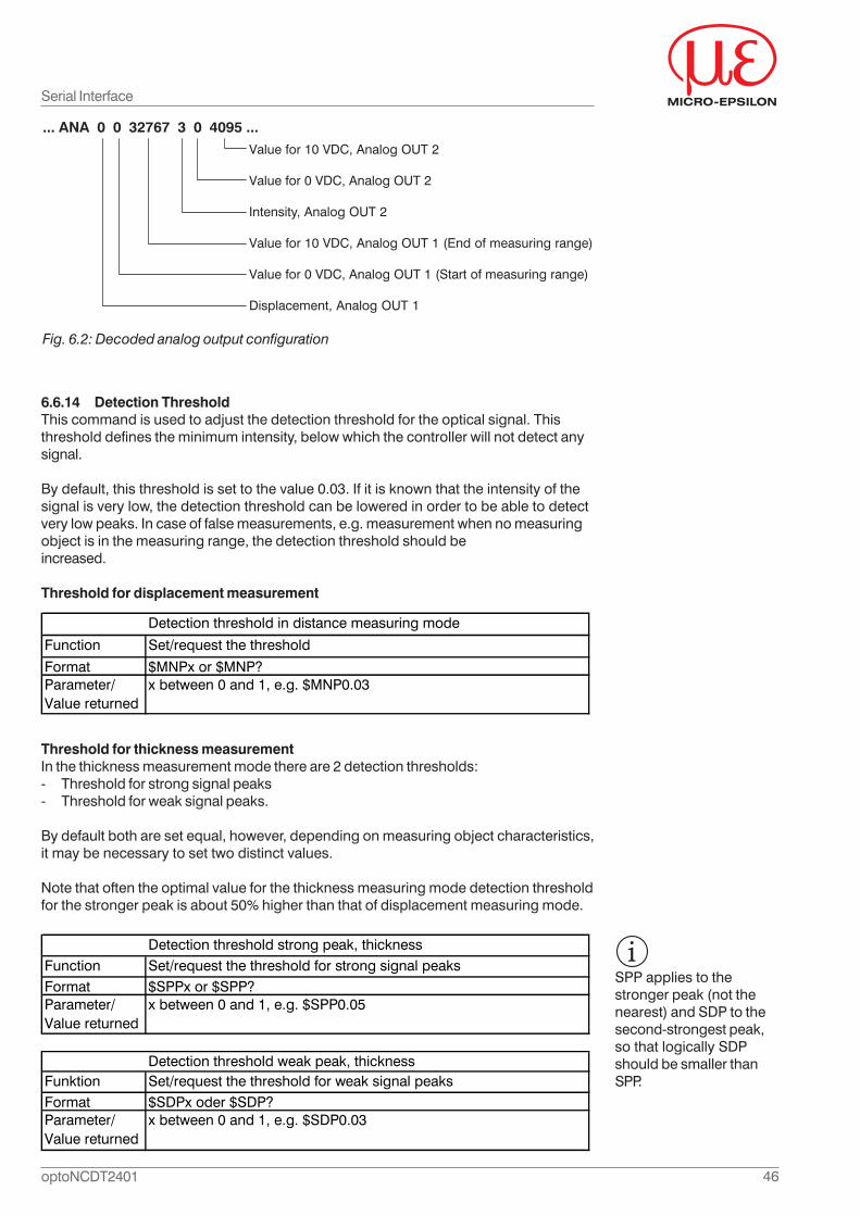
46optoNCDT2401
6.6.14 Detection ThresholdThis command is used to adjust the detection threshold for the optical signal. Thisthreshold defines the minimum intensity, below which the controller will not detect anysignal.
By default, this threshold is set to the value 0.03. If it is known that the intensity of thesignal is very low, the detection threshold can be lowered in order to be able to detectvery low peaks. In case of false measurements, e.g. measurement when no measuringobject is in the measuring range, the detection threshold should beincreased.
Threshold for displacement measurement
Threshold for thickness measurementIn the thickness measurement mode there are 2 detection thresholds:- Threshold for strong signal peaks- Threshold for weak signal peaks.
By default both are set equal, however, depending on measuring object characteristics,it may be necessary to set two distinct values.
Note that often the optimal value for the thickness measuring mode detection thresholdfor the stronger peak is about 50% higher than that of displacement measuring mode.
Serial Interface
Detection threshold in distance measuring mode
Function Set/request the threshold
Format $MNPx or $MNP?Parameter/Value returned
x between 0 and 1, e.g. $MNP0.03
Detection threshold strong peak, thicknessFunction Set/request the threshold for strong signal peaksFormat $SPPx or $SPP?Parameter/Value returned
x between 0 and 1, e.g. $SPP0.05
Detection threshold weak peak, thicknessFunktion Set/request the threshold for weak signal peaksFormat $SDPx oder $SDP?Parameter/Value returned
x between 0 and 1, e.g. $SDP0.03
... ANA 0 0 32767 3 0 4095 ...
Value for 10 VDC, Analog OUT 2
Value for 0 VDC, Analog OUT 2
Intensity, Analog OUT 2
Value for 10 VDC, Analog OUT 1 (End of measuring range)
Value for 0 VDC, Analog OUT 1 (Start of measuring range)
Displacement, Analog OUT 1
Fig. 6.2: Decoded analog output configuration
SPP applies to thestronger peak (not thenearest) and SDP to thesecond-strongest peak,so that logically SDPshould be smaller thanSPP.

47optoNCDT2401
6.6.15 Light Source TestThe role of the light source test is to indicate when the light source should be replaced.The series 2401 and 2402 controller use a LED with a very long life time, this test is notrequired. However MICRO-EPSILON recommends to enable the test for controllers withan external light source.
Enable/Disable the light source test
Threshold levelThe light source test requires a light-level below which the test fails and the “Error” LEDturns red. The threshold is adjusted using the CSL command.
6.6.16 Auto-adaptive Dark SignalIn this mode the controller measures automatically the fast dark signal (see also Chap.6.6.6) and adapts it permanently. To do so, the controller analyses the internalphotodetector signal, determines the zone occupied by the signal, and adapts the fastdark signal in all other zones.
This mode is particularly useful for external light sources whose brightness varies withtemperature and with aging.
6.6.17 Auto-adaptive Light Source BrightnessIn this mode the controller adapts automatically the light source brightness tocompensate for variations in the level of the signal returned by the measuring object.The LED brightness is modified so as to bring the signal level as close as possible to apreset threshold.
Serial Interface
Activation of the light source testFunction Enable/Disable the light source testFormat $SLPb or $SLP?Parameter/Value returned
b = 1 or 0
Threshold for light source testFunction Set/request the threshold level for the light source test
Format $CSLn or $CSL?Parameter/Value returned
n = 0 ,,, 9999
Activation of auto-adaptive darkFunction Enable/disable the auto-adaptive dark signal measuringFormat $ADKb or $ADK?Parameter/Value returned
b = 1 or 0
Auto-adaptive LEDFunction Enable/disable the auto-adaptive brightness measuringFormat $AALb or $AAL?Parameter/Value returned
b = 1 or 0
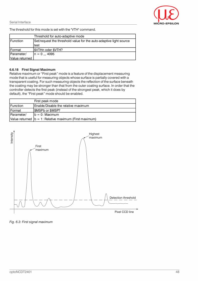
48optoNCDT2401
The threshold for this mode is set with the "VTH" command.
6.6.18 First Signal MaximumRelative maximum or “First peak” mode is a feature of the displacement measuringmode that is useful for measuring objects whose surface is partially covered with atransparent coating. For such measuring objects the reflection of the surface beneaththe coating may be stronger than that from the outer coating surface. In order that thecontroller detects the first peak (instead of the strongest peak, which it does bydefault), the “First peak” mode should be enabled.
Fig. 6.3: First signal maximum
Serial Interface
Threshold for auto-adaptive modeFunction Set/request the threshold value for the auto-adaptive light source
testFormat $VTHn oder $VTH?Parameter/Value returned
n = 0 ,,, 4095
First peak modeFunction Enable/Disable the relative maximumFormat $MSPb or $MSP?Parameter/Value returned
b = 0: Maximumb = 1: Relative maximum (First maximum)
Inte
nsity
Pixel CCD line
Detection threshold
Highest
maximum
First
maximum
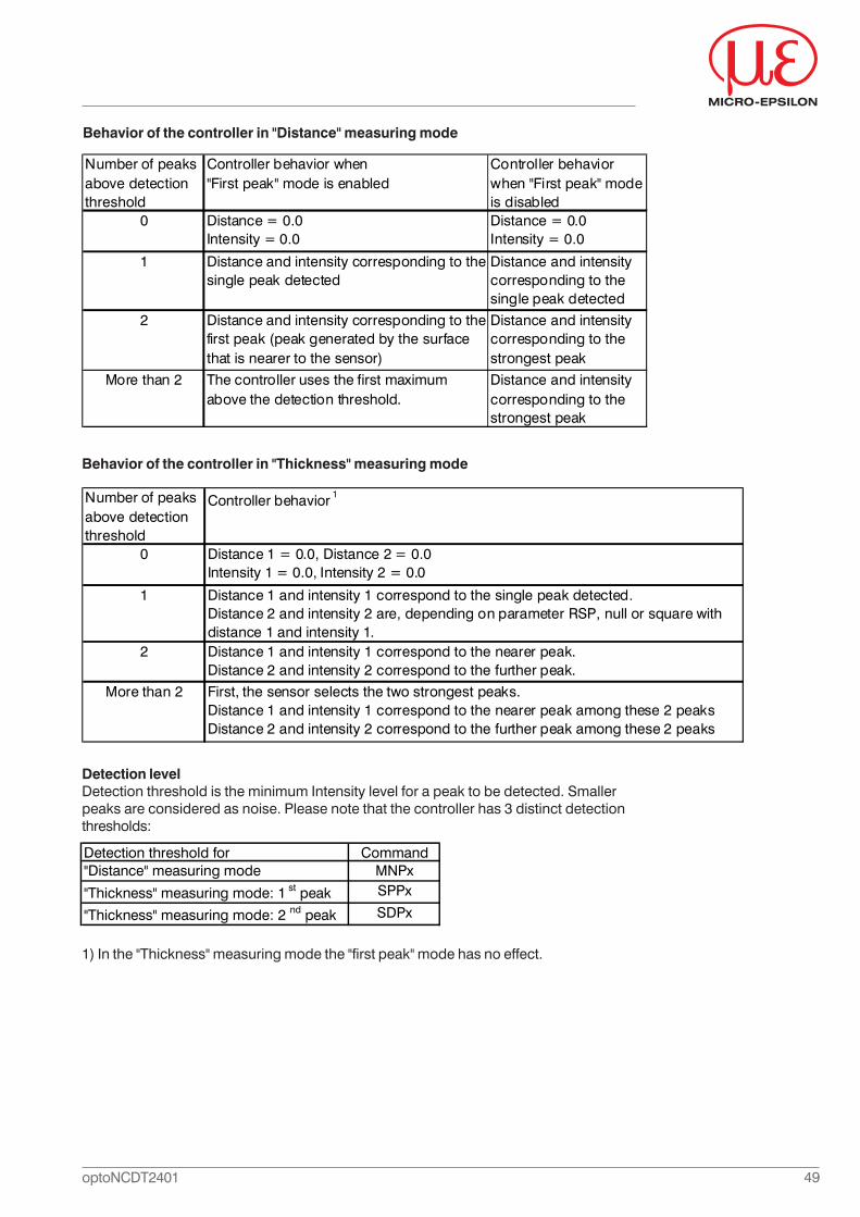
49optoNCDT2401
1) In the "Thickness" measuring mode the "first peak" mode has no effect.
Number of peaks above detection threshold
Controller behavior 1
0 Distance 1 = 0.0, Distance 2 = 0.0Intensity 1 = 0.0, Intensity 2 = 0.0
1 Distance 1 and intensity 1 correspond to the single peak detected. Distance 2 and intensity 2 are, depending on parameter RSP, null or square with distance 1 and intensity 1.
2 Distance 1 and intensity 1 correspond to the nearer peak. Distance 2 and intensity 2 correspond to the further peak.
More than 2 First, the sensor selects the two strongest peaks. Distance 1 and intensity 1 correspond to the nearer peak among these 2 peaksDistance 2 and intensity 2 correspond to the further peak among these 2 peaks
Number of peaks above detection threshold
Controller behavior when "First peak" mode is enabled
Controller behavior when "First peak" mode is disabled
0 Distance = 0.0Intensity = 0.0
Distance = 0.0Intensity = 0.0
1 Distance and intensity corresponding to the single peak detected
Distance and intensity corresponding to the single peak detected
2 Distance and intensity corresponding to the first peak (peak generated by the surface that is nearer to the sensor)
Distance and intensity corresponding to the strongest peak
More than 2 The controller uses the first maximum above the detection threshold.
Distance and intensity corresponding to the strongest peak
Behavior of the controller in "Thickness" measuring mode
Behavior of the controller in "Distance" measuring mode
Detection levelDetection threshold is the minimum Intensity level for a peak to be detected. Smallerpeaks are considered as noise. Please note that the controller has 3 distinct detectionthresholds:
Detection threshold for Command"Distance" measuring mode MNPx
"Thickness" measuring mode: 1 st peak SPPx
"Thickness" measuring mode: 2 nd peak SDPx
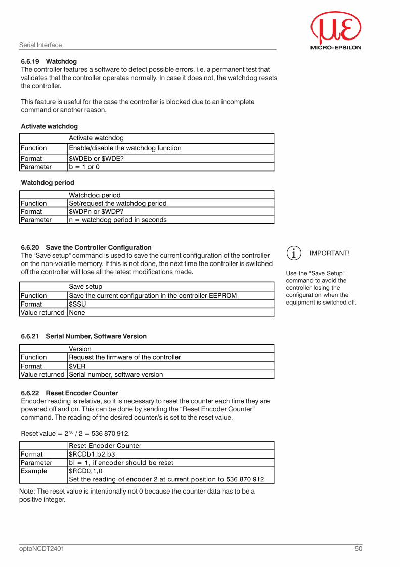
50optoNCDT2401
Reset Encoder CounterFormat $RCDb1,b2,b3Parameter bi = 1, if encoder should be resetExample $RCD0,1,0
Set the reading of encoder 2 at current position to 536 870 912
IMPORTANT!
Use the "Save Setup"command to avoid thecontroller losing theconfiguration when theequipment is switched off.
Activate watchdog
Function Enable/disable the watchdog function
Format $WDEb or $WDE?Parameter b = 1 or 0
Watchdog periodFunction Set/request the watchdog periodFormat $WDPn or $WDP?Parameter n = watchdog period in seconds
Save setupFunction Save the current configuration in the controller EEPROMFormat $SSUValue returned None
6.6.19 WatchdogThe controller features a software to detect possible errors, i.e. a permanent test thatvalidates that the controller operates normally. In case it does not, the watchdog resetsthe controller.
This feature is useful for the case the controller is blocked due to an incompletecommand or another reason.
Activate watchdog
Watchdog period
6.6.20 Save the Controller ConfigurationThe "Save setup" command is used to save the current configuration of the controlleron the non-volatile memory. If this is not done, the next time the controller is switchedoff the controller will lose all the latest modifications made.
6.6.21 Serial Number, Software Version
6.6.22 Reset Encoder CounterEncoder reading is relative, so it is necessary to reset the counter each time they arepowered off and on. This can be done by sending the “Reset Encoder Counter”command. The reading of the desired counter/s is set to the reset value.
Reset value = 2 30 / 2 = 536 870 912.
Serial Interface
VersionFunction Request the firmware of the controllerFormat $VERValue returned Serial number, software version
Note: The reset value is intentionally not 0 because the counter data has to be apositive integer.
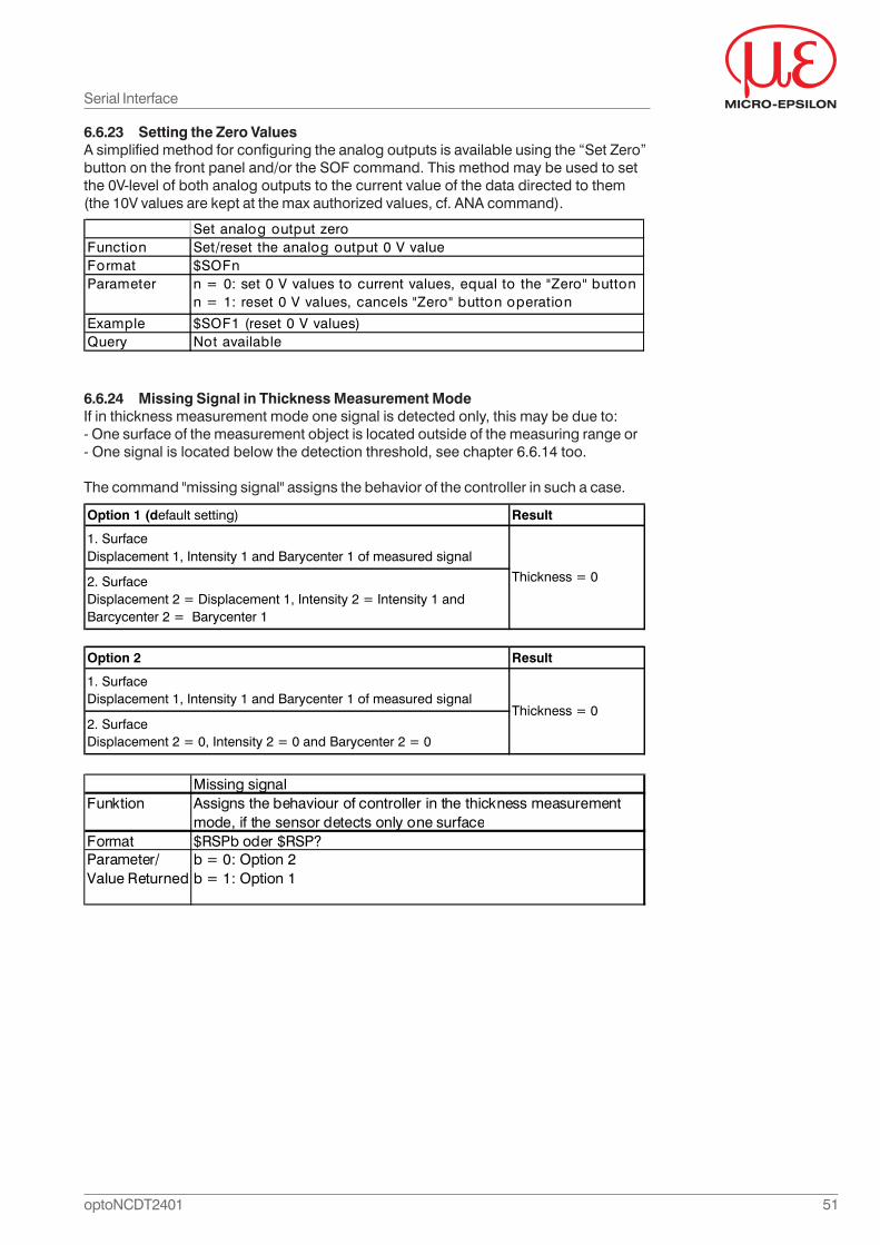
51optoNCDT2401
6.6.23 Setting the Zero ValuesA simplified method for configuring the analog outputs is available using the “Set Zero”button on the front panel and/or the SOF command. This method may be used to setthe 0V-level of both analog outputs to the current value of the data directed to them(the 10V values are kept at the max authorized values, cf. ANA command).
6.6.24 Missing Signal in Thickness Measurement ModeIf in thickness measurement mode one signal is detected only, this may be due to:- One surface of the measurement object is located outside of the measuring range or- One signal is located below the detection threshold, see chapter 6.6.14 too.
The command "missing signal" assigns the behavior of the controller in such a case.
Serial Interface
Set analog output zeroFunction Set/reset the analog output 0 V valueFormat $SOFnParameter n = 0: set 0 V values to current values, equal to the "Zero" button
n = 1: reset 0 V values, cancels "Zero" button operation
Example $SOF1 (reset 0 V values)Query Not available
Option 1 (default setting) Result
1. SurfaceDisplacement 1, Intensity 1 and Barycenter 1 of measured signal
2. SurfaceDisplacement 2 = Displacement 1, Intensity 2 = Intensity 1 and Barcycenter 2 = Barycenter 1
Thickness = 0
Option 2 Result
1. SurfaceDisplacement 1, Intensity 1 and Barycenter 1 of measured signal
2. Surface Displacement 2 = 0, Intensity 2 = 0 and Barycenter 2 = 0
Thickness = 0
Missing signalFunktion Assigns the behaviour of controller in the thickness measurement
mode, if the sensor detects only one surfaceFormat $RSPb oder $RSP?Parameter/Value Returned
b = 0: Option 2b = 1: Option 1
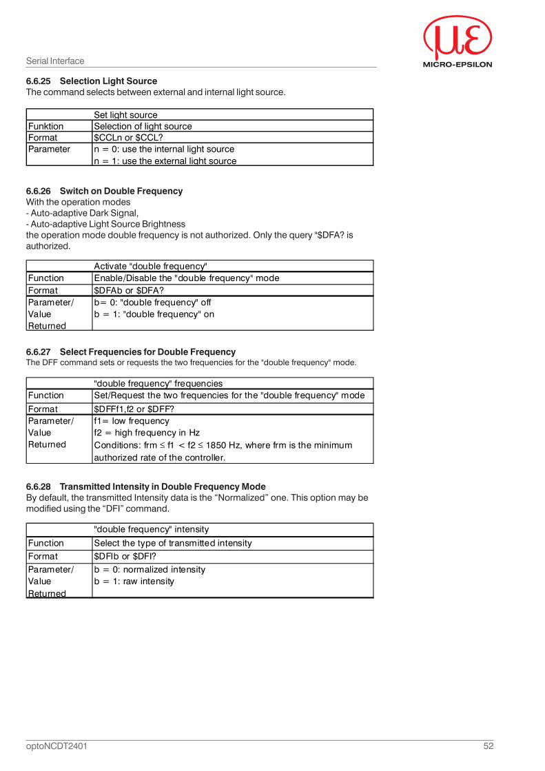
52optoNCDT2401
Set light sourceFunktion Selection of light sourceFormat $CCLn or $CCL?Parameter n = 0: use the internal light source
n = 1: use the external light source
6.6.25 Selection Light SourceThe command selects between external and internal light source.
6.6.26 Switch on Double FrequencyWith the operation modes- Auto-adaptive Dark Signal,- Auto-adaptive Light Source Brightnessthe operation mode double frequency is not authorized. Only the query "$DFA? isauthorized.
Activate "double frequency"Function Enable/Disable the "double frequency" modeFormat $DFAb or $DFA?Parameter/Value Returned
b= 0: "double frequency" offb = 1: "double frequency" on
6.6.27 Select Frequencies for Double FrequencyThe DFF command sets or requests the two frequencies for the "double frequency" mode.
"double frequency" frequenciesFunction Set/Request the two frequencies for the "double frequency" mode
Format $DFFf1,f2 or $DFF?Parameter/Value Returned
f1= low frequencyf2 = high frequency in HzConditions: frm f1 < f2 1850 Hz, where frm is the minimum authorized rate of the controller.
6.6.28 Transmitted Intensity in Double Frequency ModeBy default, the transmitted Intensity data is the “Normalized” one. This option may bemodified using the “DFI” command.
"double frequency" intensity
Function Select the type of transmitted intensityFormat $DFIb or $DFI?Parameter/Value Returned
b = 0: normalized intensityb = 1: raw intensity
Serial Interface
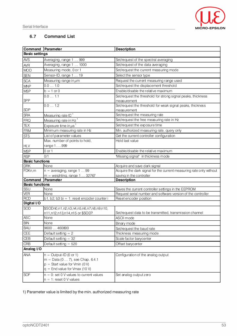
53optoNCDT2401
Serial Interface
6.7 Command List
1) Parameter value is limited by the min. authorized measuring rate
Command Parameter Description
AVS Averaging, range 1 … 999 Set/request of the spectral averaging
AVR Averaging, range 1 … 1000 Set/request of the data averaging
MOD Measuring mode, 0 or 1 Set/request the current measuring mode
SEN Sensor-ID, range 1 … 19 Select the sensor type
SCA Measuring range in μm Request the current measuring range used
MNP 0.0 … 1.0 Set/request the displacement threshold
MSP b = 1 or 0 Enable/disable the relative maximum
SPP0.0 … 1.1 Set/request the threshold for strong signal peaks, thickness
measurement
SDP0.0 … 1.2 Set/request the threshold for weak signal peaks, thickness
measurementSRA Measuring rate ID 1 Set/request the measuring rate
FRQ Measuring rate in Hz 1 Set/request the free measuring rate in Hz
TEX Exposure time in μs 1 Set/request the exposure time
FRM Minimum measuring rate in Hz Min. authorized measuring rate, query only
STS List of parameter values Get the current controller configuration
HLVMax. number of points to hold, range 1…..999
Hold last value
MSP 0 or 1 Enable/disable the relative maximum
RSP 0/1 "Missing signal" in thickness mode
DRK None Acquire and save dark signalFDKn,m n = averaging, range 1 … 99
m = weighting, range 1 … 32767Acquire the dark signal for the current measuring rate only without saving in the controller
Command Parameter Description
SSU None Saves the current controller settings in the EEPROMVER None Request serial number and software version of the controllerRCD b1, b2, b3 bi = 1: reset encoder counter i Reset encoder position
SOD $SODn0,n1,n2,n3,n4,n5,n6,n7,n8,n9,n10,n11,n12,n13,n14,n15 or $SOD? Set/request data to be transmitted, transmission channel
ASC None ASCII modeBIN None Binary modeBAU 9600 … 460800 Set/request the baud rateCEE Default setting = 2 Thickness measuring modeCEB Default setting = 32 Scale factor barycenterCRB Default setting = 520 Offset barycenter
ANA n = Output-ID (0 or 1)m = Data (0 … 7), see Chap. 6.4.1p = Start value for Vmin (0 V)q = End value for Vmax (10 V)
Configuration of the analog output
SOF n = 0: set 0 V values to current values n = 1: reset 0 V values
Set analog output zero
Basic settings
Basic functions
Digital I/O
Analog I/O
Basic functions
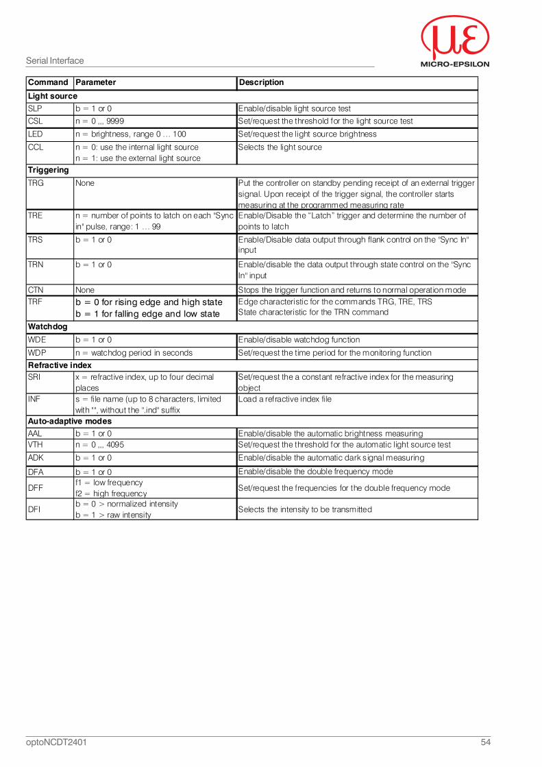
54optoNCDT2401
Command Parameter Description
SLP b = 1 or 0 Enable/disable light source test
CSL n = 0 ,,, 9999 Set/request the threshold for the light source test
LED n = brightness, range 0 … 100 Set/request the light source brightness
CCL n = 0: use the internal light source n = 1: use the external light source
Selects the light source
TRG None Put the controller on standby pending receipt of an external trigger signal. Upon receipt of the trigger signal, the controller starts measuring at the programmed measuring rate
TRE n = number of points to latch on each "Sync in" pulse, range: 1 … 99
Enable/Disable the “Latch” trigger and determine the number of points to latch
TRS b = 1 or 0 Enable/Disable data output through flank control on the "Sync In" input
TRN b = 1 or 0 Enable/disable the data output through state control on the "Sync In" input
CTN None Stops the trigger function and returns to normal operation modeTRF b = 0 for rising edge and high state
b = 1 for falling edge and low stateEdge characteristic for the commands TRG, TRE, TRSState characteristic for the TRN command
WDE b = 1 or 0 Enable/disable watchdog function
WDP n = watchdog period in seconds Set/request the time period for the monitoring function
SRI x = refractive index, up to four decimal places
Set/request the a constant refractive index for the measuring object
INF s = file name (up to 8 characters, limited with "", without the ".ind" suffix
Load a refractive index file
AAL b = 1 or 0 Enable/disable the automatic brightness measuringVTH n = 0 ,,, 4095 Set/request the threshold for the automatic light source test
ADK b = 1 or 0 Enable/disable the automatic dark signal measuring
DFA b = 1 or 0 Enable/disable the double frequency mode
DFFf1 = low frequencyf2 = high frequency
Set/request the frequencies for the double frequency mode
DFIb = 0 > normalized intensityb = 1 > raw intensity
Selects the intensity to be transmitted
Watchdog
Refractive index
Auto-adaptive modes
Light source
Triggering
Serial Interface
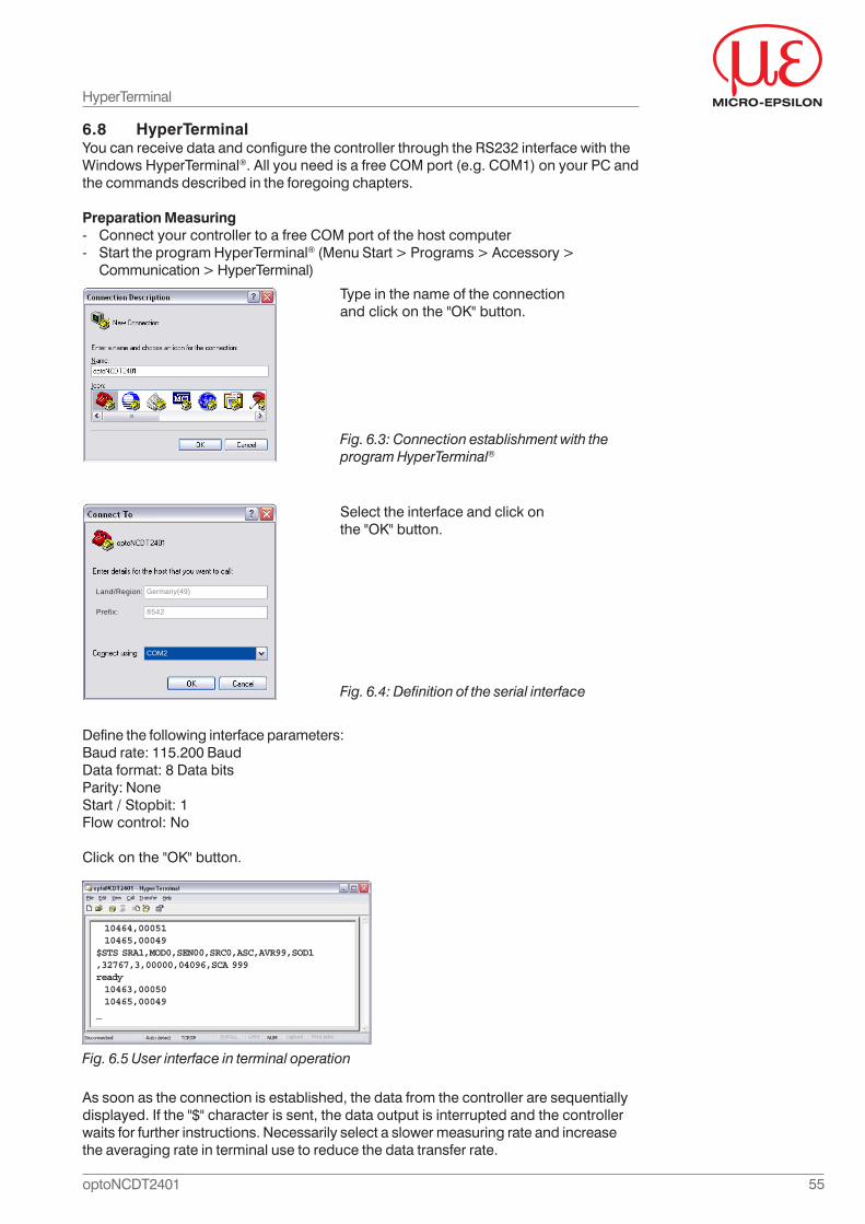
55optoNCDT2401
As soon as the connection is established, the data from the controller are sequentiallydisplayed. If the "$" character is sent, the data output is interrupted and the controllerwaits for further instructions. Necessarily select a slower measuring rate and increasethe averaging rate in terminal use to reduce the data transfer rate.
HyperTerminal
Fig. 6.5 User interface in terminal operation
Fig. 6.4: Definition of the serial interface
Select the interface and click onthe "OK" button.
Define the following interface parameters:Baud rate: 115.200 BaudData format: 8 Data bitsParity: NoneStart / Stopbit: 1Flow control: No
Click on the "OK" button.
Land/Region:
Prefix:
COM2
Germany(49)
8542
Fig. 6.3: Connection establishment with theprogram HyperTerminal®
Type in the name of the connectionand click on the "OK" button.
6.8 HyperTerminalYou can receive data and configure the controller through the RS232 interface with theWindows HyperTerminal®. All you need is a free COM port (e.g. COM1) on your PC andthe commands described in the foregoing chapters.
Preparation Measuring- Connect your controller to a free COM port of the host computer- Start the program HyperTerminal® (Menu Start > Programs > Accessory >
Communication > HyperTerminal)
10464,00051 10465,00049$STS SRA1,MOD0,SEN00,SRC0,ASC,AVR99,SOD1,32767,3,00000,04096,SCA 999ready 10463,00050 10465,00049_
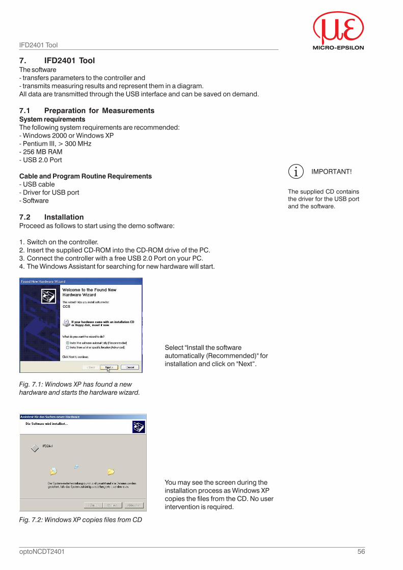
56optoNCDT2401
7. IFD2401 ToolThe software- transfers parameters to the controller and- transmits measuring results and represent them in a diagram.All data are transmitted through the USB interface and can be saved on demand.
7.1 Preparation for MeasurementsSystem requirementsThe following system requirements are recommended:- Windows 2000 or Windows XP- Pentium III, > 300 MHz- 256 MB RAM- USB 2.0 Port
Cable and Program Routine Requirements- USB cable- Driver for USB port- Software
7.2 InstallationProceed as follows to start using the demo software:
1. Switch on the controller.2. Insert the supplied CD-ROM into the CD-ROM drive of the PC.3. Connect the controller with a free USB 2.0 Port on your PC.4. The Windows Assistant for searching for new hardware will start.
IFD2401 Tool
IMPORTANT!
The supplied CD containsthe driver for the USB portand the software.
Select "Install the softwareautomatically (Recommended)" forinstallation and click on "Next“.
Fig. 7.1: Windows XP has found a newhardware and starts the hardware wizard.
You may see the screen during theinstallation process as Windows XPcopies the files from the CD. No userintervention is required.
Fig. 7.2: Windows XP copies files from CD
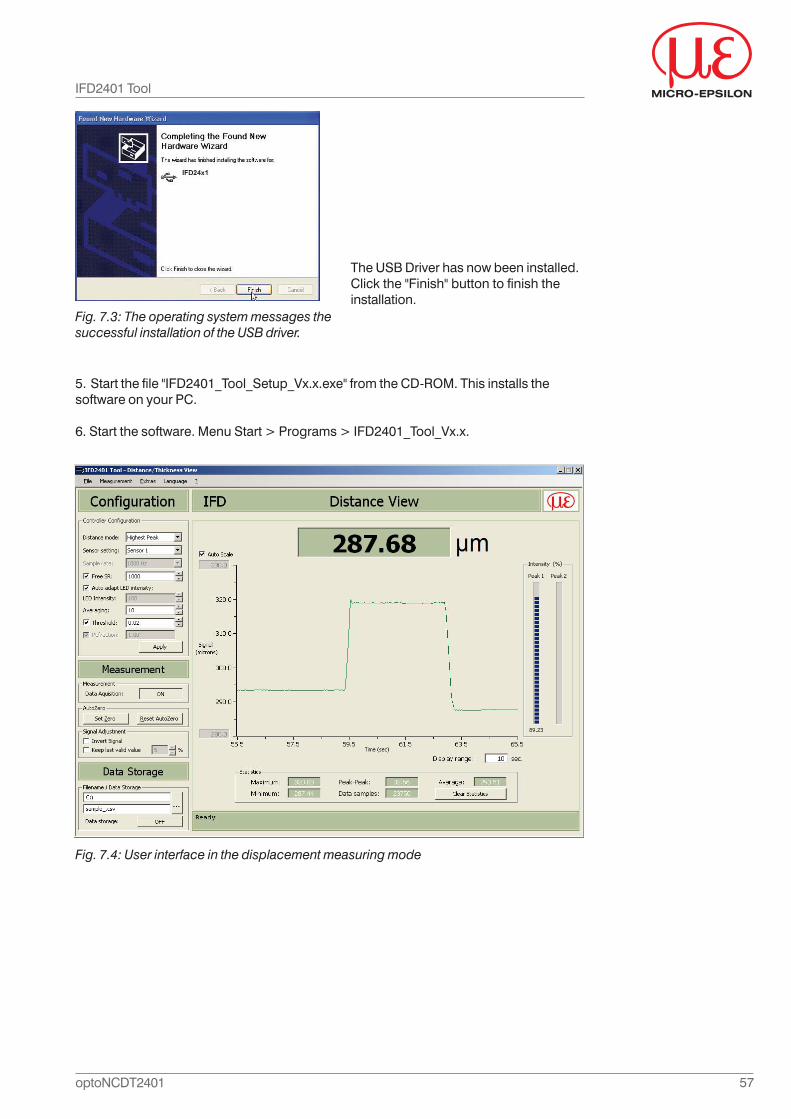
57optoNCDT2401
The USB Driver has now been installed.Click the "Finish" button to finish theinstallation.
Fig. 7.3: The operating system messages thesuccessful installation of the USB driver.
5. Start the file "IFD2401_Tool_Setup_Vx.x.exe" from the CD-ROM. This installs thesoftware on your PC.
6. Start the software. Menu Start > Programs > IFD2401_Tool_Vx.x.
Fig. 7.4: User interface in the displacement measuring mode
IFD2401 Tool
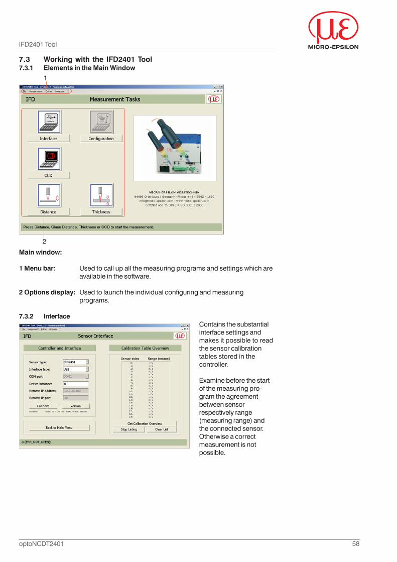
58optoNCDT2401
IFD2401 Tool
7.3 Working with the IFD2401 Tool7.3.1 Elements in the Main Window
Main window:
1 Menu bar: Used to call up all the measuring programs and settings which areavailable in the software.
2 Options display: Used to launch the individual configuring and measuringprograms.
7.3.2 InterfaceContains the substantialinterface settings andmakes it possible to readthe sensor calibrationtables stored in thecontroller.
Examine before the startof the measuring pro-gram the agreementbetween sensorrespectively range(measuring range) andthe connected sensor.Otherwise a correctmeasurement is notpossible.
1
2
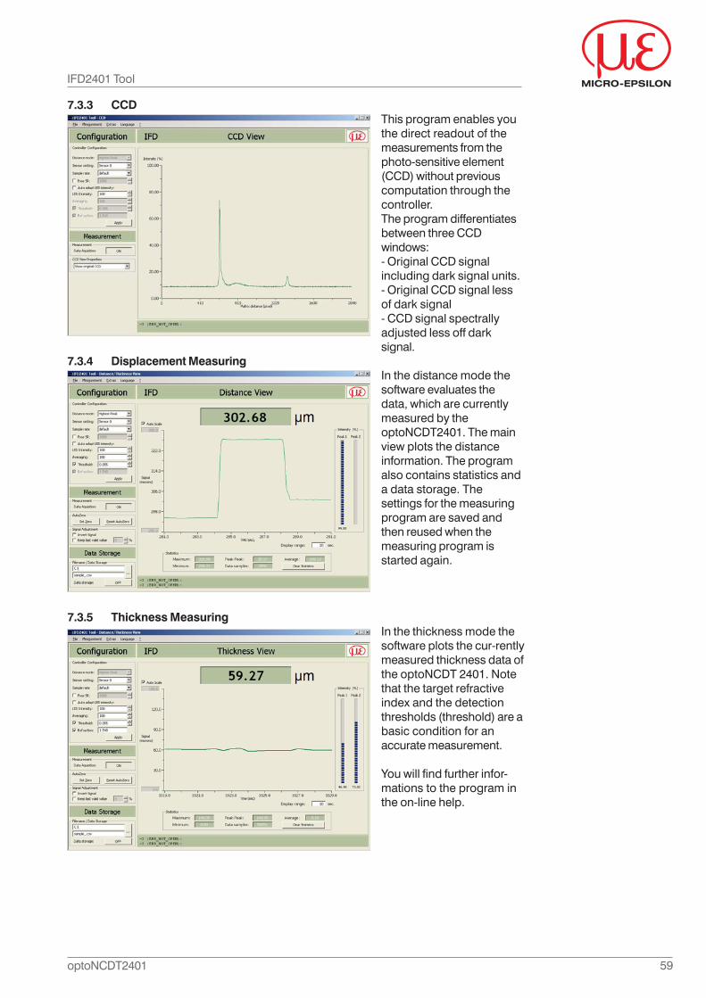
59optoNCDT2401
IFD2401 Tool
7.3.3 CCDThis program enables youthe direct readout of themeasurements from thephoto-sensitive element(CCD) without previouscomputation through thecontroller.The program differentiatesbetween three CCDwindows:- Original CCD signalincluding dark signal units.- Original CCD signal lessof dark signal- CCD signal spectrallyadjusted less off darksignal.
7.3.4 Displacement MeasuringIn the distance mode thesoftware evaluates thedata, which are currentlymeasured by theoptoNCDT2401. The mainview plots the distanceinformation. The programalso contains statistics anda data storage. Thesettings for the measuringprogram are saved andthen reused when themeasuring program isstarted again.
7.3.5 Thickness MeasuringIn the thickness mode thesoftware plots the cur-rentlymeasured thickness data ofthe optoNCDT 2401. Notethat the target refractiveindex and the detectionthresholds (threshold) are abasic condition for anaccurate measurement.
You will find further infor-mations to the program inthe on-line help.
60optoNCDT2401
Warranty
8. Warranty
All components of the system have been checked and tested for perfect function in thefactory.
In the unlikely event that errors should occur despite our thorough quality control, thisshould be reported immediately to MICRO-EPSILON.
The warranty period lasts 12 months following the day of shipment. Defective parts,except wear parts, will be repaired or replaced free of charge within this period if youreturn the device free of cost to MICRO-EPSILON.
This warranty does not apply to damage resulting from abuse of the equipment, fromforceful handling or installation of the devices or from repair or modifications performedby third parties.
Repairs must be exclusively done by MICRO-EPSILON.
No other claims, except as warranted, are accepted. The terms of the purchasingcontract apply in full.
MICRO-EPSILON will specifically not be responsible for eventual consequentialdamage.
MICRO-EPSILON always strives to supply it's customers with the finest and mostadvanced equipment. Development and refinement is therefore performedcontinuously and the right to design changes without prior notice is accordinglyreserved.
For translations in other languages, the data and statements in the German languageoperation manual are to be taken as authoritative.
9. Decommissioning, Disposal
- Disconnect the power supply and output cable on the controller.- Disconnect the sensor cable between sensor and controller.The optoNCDT240x is produced according to the directive 2002/95/EC („RoHS“). Thedisposal is done according to the legal regulations (see directive 2002/96/EC).
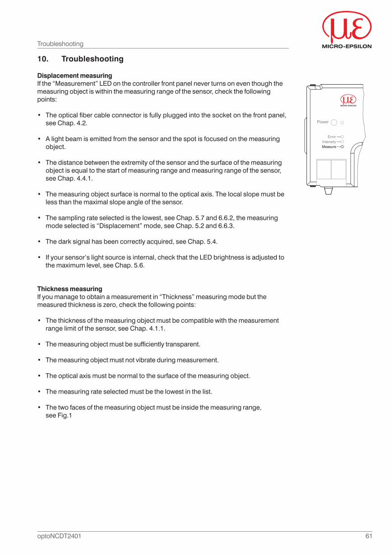
61optoNCDT2401
10. Troubleshooting
Displacement measuringIf the “Measurement” LED on the controller front panel never turns on even though themeasuring object is within the measuring range of the sensor, check the followingpoints:
• The optical fiber cable connector is fully plugged into the socket on the front panel,see Chap. 4.2.
• A light beam is emitted from the sensor and the spot is focused on the measuringobject.
• The distance between the extremity of the sensor and the surface of the measuringobject is equal to the start of measuring range and measuring range of the sensor,see Chap. 4.4.1.
• The measuring object surface is normal to the optical axis. The local slope must beless than the maximal slope angle of the sensor.
• The sampling rate selected is the lowest, see Chap. 5.7 and 6.6.2, the measuringmode selected is “Displacement” mode, see Chap. 5.2 and 6.6.3.
• The dark signal has been correctly acquired, see Chap. 5.4.
• If your sensor’s light source is internal, check that the LED brightness is adjusted tothe maximum level, see Chap. 5.6.
Thickness measuringIf you manage to obtain a measurement in “Thickness” measuring mode but themeasured thickness is zero, check the following points:
• The thickness of the measuring object must be compatible with the measurementrange limit of the sensor, see Chap. 4.1.1.
• The measuring object must be sufficiently transparent.
• The measuring object must not vibrate during measurement.
• The optical axis must be normal to the surface of the measuring object.
• The measuring rate selected must be the lowest in the list.
• The two faces of the measuring object must be inside the measuring range,see Fig.1
Troubleshooting
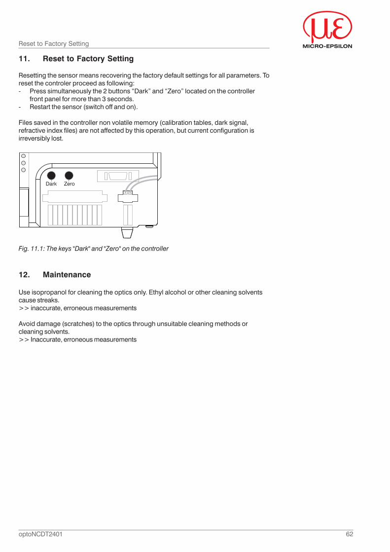
62optoNCDT2401
11. Reset to Factory Setting
Resetting the sensor means recovering the factory default settings for all parameters. Toreset the controler proceed as following:- Press simultaneously the 2 buttons “Dark” and “Zero” located on the controller
front panel for more than 3 seconds.- Restart the sensor (switch off and on).
Files saved in the controller non volatile memory (calibration tables, dark signal,refractive index files) are not affected by this operation, but current configuration isirreversibly lost.
Fig. 11.1: The keys "Dark" and "Zero" on the controller
Reset to Factory Setting
12. Maintenance
Use isopropanol for cleaning the optics only. Ethyl alcohol or other cleaning solventscause streaks.>> inaccurate, erroneous measurements
Avoid damage (scratches) to the optics through unsuitable cleaning methods orcleaning solvents.>> Inaccurate, erroneous measurements

63optoNCDT2401

MICRO-EPSILONMESSTECHNIK
GmbH & Co. KGKönigbacher Strasse 15
D-94496 OrtenburgTel. +49/85 42/1 68-0
Fax +49/85 42/1 68-90e-mail: [email protected]
X9751170-A111040HDR
MICRO-EPSILON
www.micro-epsilon.de
*X9751170-A11*