Embed Size (px)
Citation preview
MICRO-EPSILON
SENSORS & SYSTEMS
Authority in Displacement Measuring
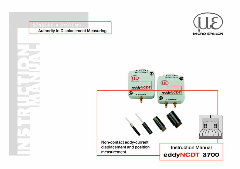
Instruction Manual
eddyNCDT 3700
Non-contact eddy-current
displacement and position
measurement
MICRO-EPSILON
MESSTECHNIK
GmbH & Co. KG
Koenigbacher Strasse 15
D-94496 Ortenburg
Tel. +49/85 42/1 68-0
Fax +49/85 42/1 68-90
e-mail [email protected]
www.micro-epsilon.com
Certified acc. to DIN EN ISO 9001: 2000
X9751106-A050046MSC
Content
1. Safety ............................................................................................................. 51.1 Symbols Used................................................................................................................... 5
1.2 Warnings ........................................................................................................................... 5
1.3 Notes on CE Identification ................................................................................................ 6
1.4 Proper Use ........................................................................................................................ 7
1.5 Proper Environment .......................................................................................................... 7
2. System Description ...................................................................................... 82.1 Measurement Principle ...................................................................................................... 8
2.2 Structure of the Measurement System .............................................................................. 8
2.3 Glossary .......................................................................................................................... 10
2.4 Technical Data ................................................................................................................. 12
3. Delivery ....................................................................................................... 143.1 Supplied Items, Unpacking ............................................................................................. 14
3.2 Storage ........................................................................................................................... 14
4. Installation and Assembly .......................................................................... 154.1 Precautions ..................................................................................................................... 15
4.2 Sensor ............................................................................................................................. 15
4.2.1 Start of Measuring Range ............................................................................................... 16
4.2.2 Standard Mounting ......................................................................................................... 17
4.2.3 Flush Mounting ............................................................................................................... 18
4.3 Sensor Cable .................................................................................................................. 19
4.4 Controller ........................................................................................................................ 19
X9751106-A050046MSC
4.5 Connecting the Measurement System ............................................................................ 20
4.5.1 Power Supply and Reverse Voltage Protection .............................................................. 20
4.5.2 Signal Output .................................................................................................................. 21
4.5.2 Sensor ............................................................................................................................. 22
5. Operation..................................................................................................... 225.1 Zero and Gain ................................................................................................................. 22
5.2 Differential system DT3703 .............................................................................................. 24
6. Warranty ...................................................................................................... 26
7. Appendix...................................................................................................... 27
X9751106-A050046MSC Seite 5
Safety
1. Safety1.1 Symbols UsedKnowledge of the operating instructions is a prerequisite for equipment operation. The following symbols are
used in this instruction manual:
DANGER! - imminent danger
WARNING! - potentially dangerous situation
i IMPORTANT! - useful tips and information
1.2 Warnings• Avoid banging and knocking the sensor and/or the controller
� Damage to or destruction of the sensor and/or the controller
• The power supply may not exceed the specified limits
� Damage to or destruction of the controller and/or the sensor
� Danger of injury
• Power supply and the display-/output device must be connected in accordance with the safety
regulations for electrical equipment
� Danger of injury
� Damage to or destruction of the sensor and/or the controller
• Protect the sensor cable against damage
� Destruction of the sensor and/or the controller
� Failure of the measuring device
Seite 6 X9751106-A050046MSC
1.3 Notes on CE IdentificationThe following applies to the eddyNCDT series 3700:
EC regulation 89/336/EEC
Products which carry the CE mark satisfy the requirements of the EC regulation EC 89/336/EEC
‘Electromagnetic Compatibility’ and the European standards (EN) listed therein. The EC declaration of
conformity is kept available according to EC regulation, article 10 by the authorities responsible at
MICRO-EPSILON MESSTECHNIK
GmbH & Co. KG
Koenigbacher Straße 15
94496 Ortenburg
The eddyNCDT series 3700 measuring system is designed for use in industry and satisfy the requirements of
the standards
• EN 61000-6-3 RFI emission
• EN 61000-6-2 Immunity to interference
The eddyNCDT series 3700 measuring system satisfies the requirements if the system is operated according
to the regulations described in the operating manual for installation and operation.
Safety
X9751106-A050046MSC Seite 7
1.4 Proper Use
• The eddyNCDT series 3700 measuring system is designed for use in industrial areas.
• It is used for
- displacement, distance, thickness and movement measurement
- position measuring of parts or machine components
• The measuring system may only be operated within the limits specified in the technical data.
• The system should only be used in such a way that in case of malfunction or failure personnel or
machinery are not endanged.
• Additional precautions for safety and damage prevention must be taken for safety-related applications.
1.5 Proper Environment
• Temperature: -50 to +150 °C (-58 to +302 °F) sensor and cable
+10 to +60 °C (+50 to +140 °F) controller
• Humidity: 5 - 95 % (no condensation)
• Ambient pressure: atmospheric pressure
• EMC: According to EN 61000-6-3 RFI emission
EN 61000-6-2 Immunity to interference
• Storage temperature: -50 to +150 °C (-58 to +302 °F) sensor and cable
-25 to +75 °C (-13 to +167 °F) controller
• Vibration/Shock: EN 60068-2
Safety
Seite 8 X9751106-A050046MSC
System Description
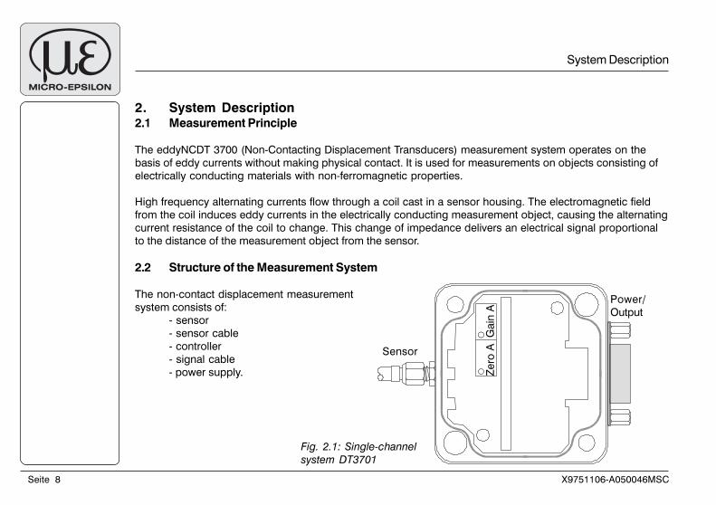
2. System Description2.1 Measurement Principle
The eddyNCDT 3700 (Non-Contacting Displacement Transducers) measurement system operates on the
basis of eddy currents without making physical contact. It is used for measurements on objects consisting of
electrically conducting materials with non-ferromagnetic properties.
High frequency alternating currents flow through a coil cast in a sensor housing. The electromagnetic field
from the coil induces eddy currents in the electrically conducting measurement object, causing the alternating
current resistance of the coil to change. This change of impedance delivers an electrical signal proportional
to the distance of the measurement object from the sensor.
2.2 Structure of the Measurement System
The non-contact displacement measurement
system consists of:
- sensor
- sensor cable
- controller
- signal cable
- power supply.
Fig. 2.1: Single-channel
system DT3701
Sensor
Power/
Output
Ze
ro A
G
ain
A
X9751106-A050046MSC Seite 9
System Description
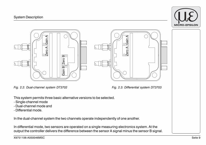
Fig. 2.2: Dual-channel system DT3702 Fig. 2.3: Differential system DT3703
Ga
in B
Z
ero
B
Ze
ro A
G
ain
A
Ze
ro A
G
ain
A
This system permits three basic alternative versions to be selected.
- Single-channel mode
- Dual-channel mode and
- Differential mode.
In the dual-channel system the two channels operate independently of one another.
In differential mode, two sensors are operated on a single measuring electronics system. At the
output the controller delivers the difference between the sensor A signal minus the sensor B signal.
Seite 10 X9751106-A050046MSC
If the sensor is replaced by another of the same type or if the sensor cable is replaced:
- check calibration and, if necessary, recalibrate the measuring channel (see Chapter 5.1).
If the sensor is replaced by another of a different type, the length of the sensor cable is changed or the non-
ferromagnetic measurement object material is changed:
- check calibration and, if necessary, recalibrate the measuring channel (see Chapter 5.1).
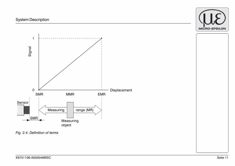
2.3 Glossary
SMR Start of measuring range. Minimum distance between the sensor front and the object to be measured.
MMR Midrange
EMR End of measuring range (Start of measuring range + measuring range).
Maximum distance between the sensor front and the object to be measured.
MR Measuring range
System Description
X9751106-A050046MSC Seite 11
System Description
Fig. 2.4: Definition of terms
0
1
Measuring
object
Sensor
Measuring range (MR)
SMR MMR EMRDisplacement
SMR
Sig
na
l
Seite 12 X9751106-A050046MSC
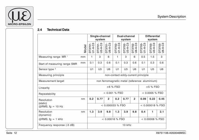
2.4 Technical Data
System Description
lennahc-elgniS
metsys
lennahc-lauD
metsys
laitnereffiD
metsys
egnargnirusaeM RM 1 mm 1 3 6 1 3 6 5.0 5.1 3
RMSegnargnirusaemfotratS mm 1.0 3.0 6.0 1.0 3.0 6.0 1.0 3.0 6.0
epytrosneS 2 1U 3U 6U 1U 3U 6U 1U 3U 6U
elpicnirpgnirusaeM elpicnirptnerruc-yddetcatnoc-non
tegrattnemerusaeM )muinimula:ecnerefer(latemcitengamorrefnon
ytiraeniL OSF%6± OSF%5±
ytilibataepeR OSF%100.0< OSF%5000.0<
noituloseR
)citats(
zH01=gf,SMR@
mn 2.0 77.0 2 2.0 77.0 2 90.0 22.0 54.0
OSF%330000.0< OSF%810000.0<
noituloseR
)cimanyd(
mn 3.1 9.3 8.9 3.1 9.3 8.9 4.0 1 1.2
zHk1=gf,SMR@ OSF%61000.0< OSF%80000.0<
)Bd3-(esnopserycneuqerF zHk01
DT
37
01
-
U1
-A-C
3
DT
37
01
-
U6
-A-C
3
DT
37
01
-
U3
-A-C
3
DT
37
03
-
U1
-A-C
3
DT
37
03
-
U6
-A-C
3
DT
37
03
-
U3
-A-C
3
DT
37
02
-
U1
-A-C
3
DT
37
02
-
U6
-A-C
3
DT
37
02
-
U3
-A-C
3
Mo
de
l
X9751106-A050046MSC Seite 13
All data apply for aluminium at 20 °C, FSO = Full Scale Output,1) Measuring ranges for OEM applications on request2) Sensor models for OEM applications on request (more then 500 different sensor models are available)3) -2.5 ... 0 V / -2.5 ... 2.5 V / -2.5 ... 5 V / -2.5 ... 10 V / 0 ... 2.5 V / 0 ... 5 V / 4 ... 20 mA for OEM applications on request
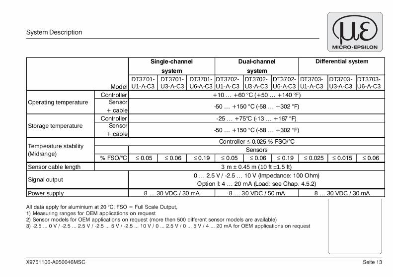
System Description
DT3701-U1-A-C3
DT3701-U3-A-C3
DT3701-U6-A-C3
DT3702-U1-A-C3
DT3702-U3-A-C3
DT3702-U6-A-C3
DT3703-U1-A-C3
DT3703-U3-A-C3
DT3703-U6-A-C3
ControllerSensor
+ cableController
Sensor+ cable
% FSO/°C 0.05 0.06 0.19 0.05 0.06 0.19 0.025 0.015 0.06Sensor cable length
Model
Power supply
Signal output
Temperature stability(Midrange)
Operating temperature
Storage temperature
Controller 0.025 % FSO/°CSensors
3 m ± 0.45 m (10 ft ±1.5 ft)
0 … 2.5 V / -2.5 … 10 V (Impedance: 100 Ohm)Option I: 4 … 20 mA (Load: see Chap. 4.5.2)
8 … 30 VDC / 30 mA 8 … 30 VDC / 50 mA 8 … 30 VDC / 30 mA
Differential systemDual-channel
system
Single-channel
system
+10 … +60 °C (+50 … +140 °F)
-50 … +150 °C (-58 … +302 °F)
-25 … +75°C (-13 … +167 °F)
-50 … +150 °C (-58 … +302 °F)
Seite 14 X9751106-A050046MSC
Lieferung
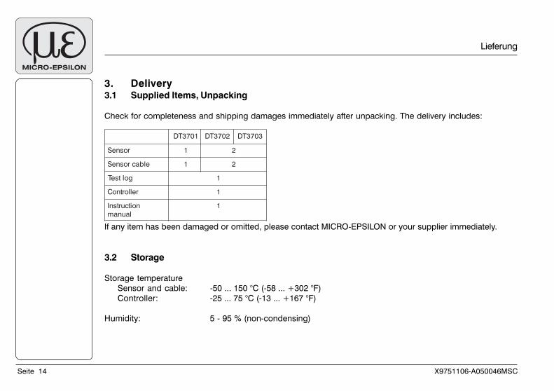
3. Delivery3.1 Supplied Items, Unpacking
Check for completeness and shipping damages immediately after unpacking. The delivery includes:
If any item has been damaged or omitted, please contact MICRO-EPSILON or your supplier immediately.
3.2 Storage
Storage temperature
Sensor and cable: -50 ... 150 °C (-58 ... +302 °F)
Controller: -25 ... 75 °C (-13 ... +167 °F)
Humidity: 5 - 95 % (non-condensing)
1073TD 2073TD 3073TD
rosneS 1 2
elbacrosneS 1 2
goltseT 1
rellortnoC 1
noitcurtsnI
launam
1
X9751106-A050046MSC Seite 15
Installation and Assembly
4. Installation and Assembly4.1 Precautions
No sharp or heavy objects should be allowed to affect the cable sheath of the sensor cable, the supply cable
and of the output cable. All plug-in connections must be checked for firm seating before starting operation.
4.2 Sensor
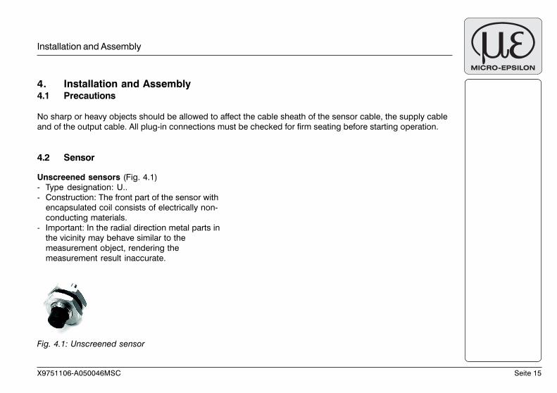
Fig. 4.1: Unscreened sensor
Unscreened sensors (Fig. 4.1)
- Type designation: U..
- Construction: The front part of the sensor with
encapsulated coil consists of electrically non-
conducting materials.
- Important: In the radial direction metal parts in
the vicinity may behave similar to the
measurement object, rendering the
measurement result inaccurate.
Seite 16 X9751106-A050046MSC
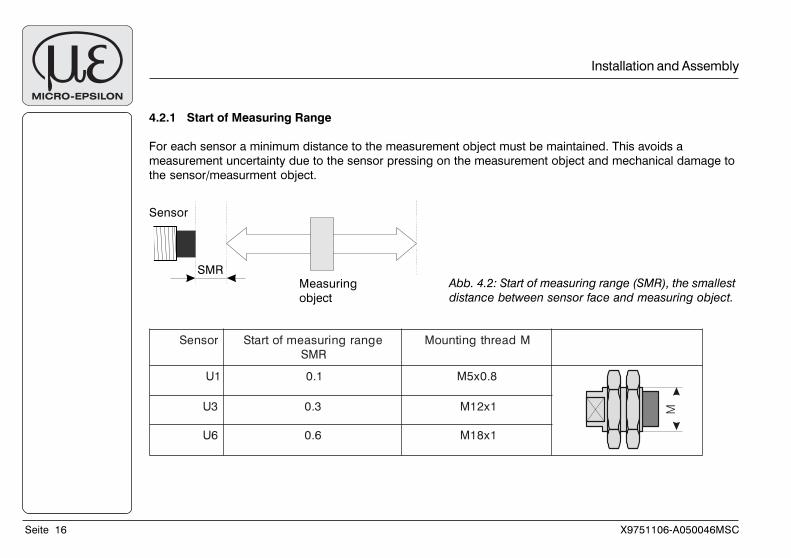
4.2.1 Start of Measuring Range
For each sensor a minimum distance to the measurement object must be maintained. This avoids a
measurement uncertainty due to the sensor pressing on the measurement object and mechanical damage to
the sensor/measurment object.
Abb. 4.2: Start of measuring range (SMR), the smallest
distance between sensor face and measuring object.
Sensor
Measuring
object
SMR
Installation and Assembly
rosneS egnargnirusaemfotratSRMS
MdaerhtgnitnuoM
1U 1.0 8.0x5M
3U 3.0 1x21M
6U 6.0 1x81M
M
X9751106-A050046MSC Seite 17
i IMPORTANT!
The standard
mounting of the
sensor should be
preferred, because
the optimum
measurement results
can be achieved with
this method.
i IMPORTANT!
During calibration
maintain the same
relative position of the
sensor to the holder
as for the
measurement.
Installation and Assembly
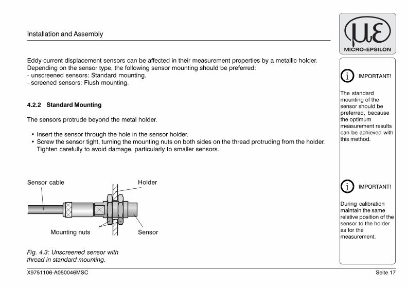
Eddy-current displacement sensors can be affected in their measurement properties by a metallic holder.
Depending on the sensor type, the following sensor mounting should be preferred:
- unscreened sensors: Standard mounting.
- screened sensors: Flush mounting.
4.2.2 Standard Mounting
The sensors protrude beyond the metal holder.
• Insert the sensor through the hole in the sensor holder.
• Screw the sensor tight, turning the mounting nuts on both sides on the thread protruding from the holder.
Tighten carefully to avoid damage, particularly to smaller sensors.
Fig. 4.3: Unscreened sensor with
thread in standard mounting.
Mounting nuts
Holder
Sensor
Sensor cable
Seite 18 X9751106-A050046MSC
i IMPORTANT!
Calibrate the
measurement system
in the measurement
arrangement with the
original mounted
sensor.
≥ 3
x S
en
so
r
dia
me
ter
Installation and Assembly
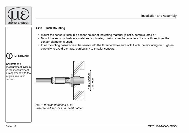
4.2.3 Flush Mounting
• Mount the sensors flush in a sensor holder of insulating material (plastic, ceramic, etc.) or
• Mount the sensors flush in a metal sensor holder, making sure that a recess of a size three times the
sensor diameter is used.
• In all mounting cases screw the sensor into the threaded hole and lock it with the mounting nut. Tighten
carefully to avoid damage, particularly to smaller sensors.
Fig. 4.4: Flush mounting of an
unscreened sensor in a metal holder.
X9751106-A050046MSC Seite 19
i IMPORTANT!
In pressurized areas
protect the cable
from pressurization.
Installation and Assembly
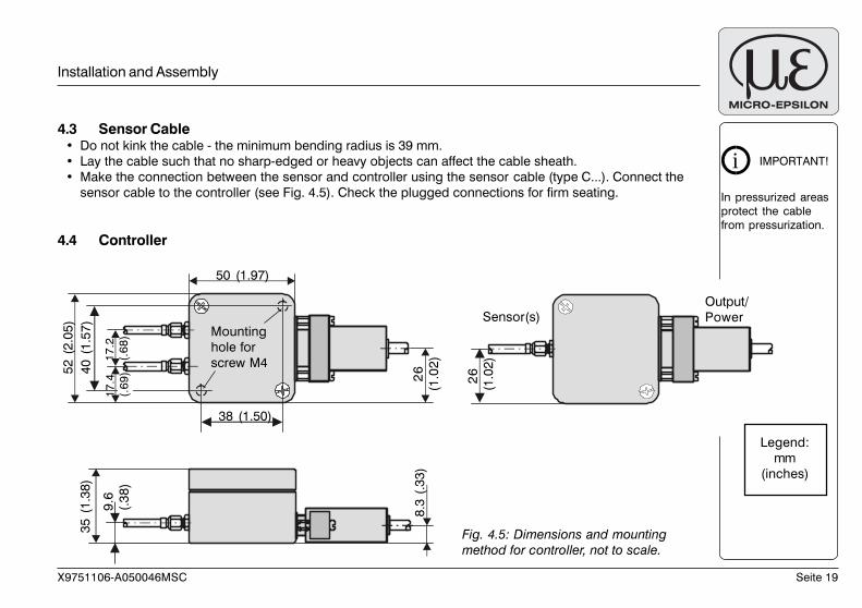
4.3 Sensor Cable• Do not kink the cable - the minimum bending radius is 39 mm.
• Lay the cable such that no sharp-edged or heavy objects can affect the cable sheath.
• Make the connection between the sensor and controller using the sensor cable (type C...). Connect the
sensor cable to the controller (see Fig. 4.5). Check the plugged connections for firm seating.
4.4 Controller
Legend:
mm
(inches)
Fig. 4.5: Dimensions and mounting
method for controller, not to scale.
8.3
(.3
3)
26
(1.0
2)
26
(1
.02
)
35
(1
.38
)
9.6
(.3
8)
52
(2
.05
)
40
(1
.57
)
17
.2
(.6
8)
38 (1.50)
50 (1.97)
Mounting
hole for
screw M4
Sensor(s)Output/
Power
17
.4
(.6
9)
Seite 20 X9751106-A050046MSC
i IMPORTANT!
The power supply
PS2010 is available
as an accessory.
4.5 Connecting the Measurement System4.5.1 Power Supply and Reverse Voltage Protection
The electronics are supplied with voltage which must not fall outside the range of 8 - 30 VDC. The minimum
supply voltage is always dependent on the maximum output voltage pre-set at the factory (see Tab. 4.1). For
short periods a maximum of 35 VDC is permitted. The negative supply voltage and reference voltage is self-
generated by means of a charge pump.
If the controller is run at the lowest supply voltage limit this will reduce the power loss-based heating up of the
electronic system and will reduce its warm-up time.
UTUO
,RMS yrotcafxe UTUO
,RME yrotcafxe UYLPPUS
.nim
CDV5.2- CDV0 CDV8
CDV5.2- CDV5.2+ CDV8
CDV5.2- CDV5+ CDV7.8
CDV5.2- CDV01+ CDV5.21
CDV0 CDV5.2+ CDV8
CDV0 CDV5+ CDV7.8
CDV0 CDV01+ CDV5.21
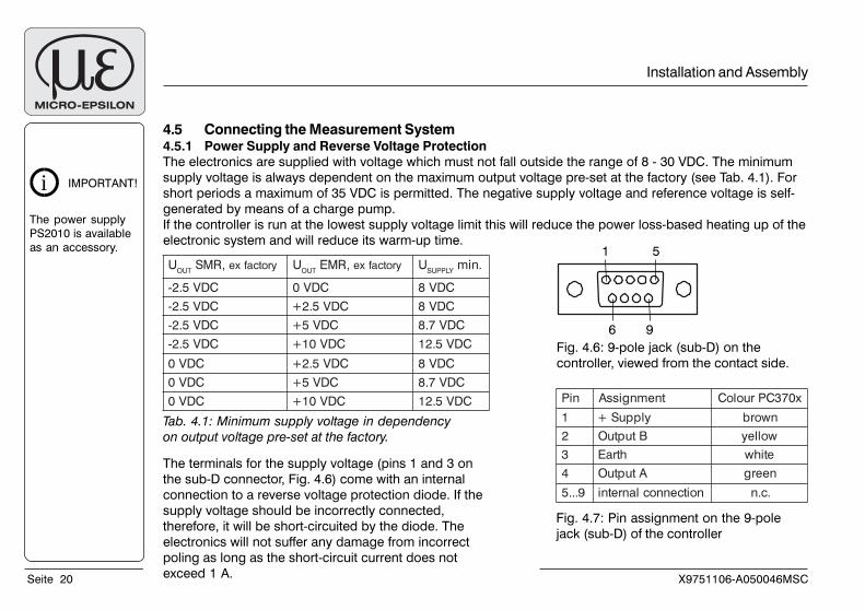
The terminals for the supply voltage (pins 1 and 3 on
the sub-D connector, Fig. 4.6) come with an internal
connection to a reverse voltage protection diode. If the
supply voltage should be incorrectly connected,
therefore, it will be short-circuited by the diode. The
electronics will not suffer any damage from incorrect
poling as long as the short-circuit current does not
exceed 1 A.
Installation and Assembly
1 5
6 9
Fig. 4.6: 9-pole jack (sub-D) on the
controller, viewed from the contact side.
niP tnemngissA x073CPruoloC
1 ylppuS+ nworb
2 BtuptuO wolley
3 htraE etihw
4 AtuptuO neerg
9...5 noitcennoclanretni .c.n
Fig. 4.7: Pin assignment on the 9-pole
jack (sub-D) of the controller
Tab. 4.1: Minimum supply voltage in dependency
on output voltage pre-set at the factory.
X9751106-A050046MSC Seite 21
4.5.2 Signal Output
The output impedance for the voltage output is 100 Ohm.
Channel isolation in the dual-channel system is ≥ 66 dB.
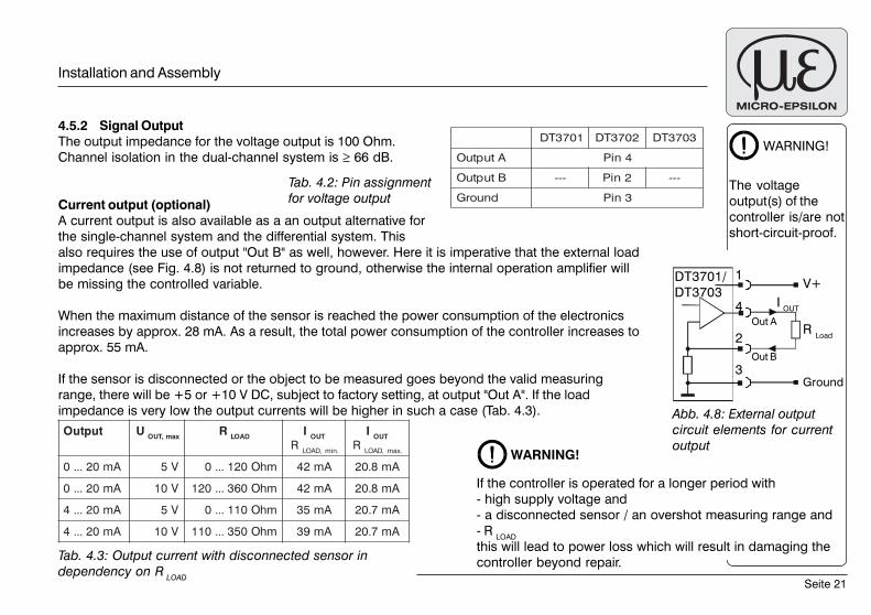
Current output (optional)
A current output is also available as a an output alternative for
the single-channel system and the differential system. This
also requires the use of output "Out B" as well, however. Here it is imperative that the external load
impedance (see Fig. 4.8) is not returned to ground, otherwise the internal operation amplifier will
be missing the controlled variable.
When the maximum distance of the sensor is reached the power consumption of the electronics
increases by approx. 28 mA. As a result, the total power consumption of the controller increases to
approx. 55 mA.
If the sensor is disconnected or the object to be measured goes beyond the valid measuring
range, there will be +5 or +10 V DC, subject to factory setting, at output "Out A". If the load
impedance is very low the output currents will be higher in such a case (Tab. 4.3).
Tab. 4.2: Pin assignment
for voltage output
tuptuO Uxam,TUO
RDAOL
ITUO
R,DAOL .nim
ITUO
R,DAOL .xam
Am02...0 V5 mhO021...0 Am24 Am8.02
Am02...0 V01 mhO063...021 Am24 Am8.02
Am02...4 V5 mhO011...0 Am53 Am7.02
Am02...4 V01 mhO053...011 Am93 Am7.02
WARNING!
The voltage
output(s) of the
controller is/are not
short-circuit-proof.
Abb. 4.8: External output
circuit elements for current
output
If the controller is operated for a longer period with
- high supply voltage and
- a disconnected sensor / an overshot measuring range and
- R LOAD
this will lead to power loss which will result in damaging the
controller beyond repair.Tab. 4.3: Output current with disconnected sensor in
dependency on R LOAD
WARNING!
Installation and Assembly
1073TD 2073TD 3073TD
AtuptuO 4niP
BtuptuO --- 2niP ---
dnuorG 3niP
1
4
2
3
Out A
Out B
Ground
DT3701/
DT3703V+
I OUT
R Load
Seite 22 X9751106-A050046MSC
4.5.2 Sensor
The sensor, including the sensor cable, is connected to the SMC jack (see Fig. 2.1). The SMC jack and the
sub-D connector are connected to ground potential.
5. OperationCheck that the measuring system is correctly set up.
1) Is the supply voltage connected?
2) Is the sensor connected?
3) Are the cable connections securely attached?
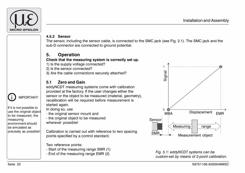
5.1 Zero and GaineddyNCDT measuring systems come with calibration
provided at the factory. If the user changes either the
sensor or the object to be measured (material, geometry),
recalibration will be required before measurement is
started again.
In doing so, use
- the original sensor mount and
- the original object to be measured
wherever possible!
Calibration is carried out with reference to two spacing
points specified by a control standard.
Two reference points:
- Start of the measuring range SMR (1)
- End of the measuring range EMR (2)
i IMPORTANT!
If it is not possible to
use the original object
to be measured, the
measuring
environment should
be simulated as
precisely as possible!
Installation and Assembly
Fig. 5.1: eddyNCDT systems can be
custom-set by means of 2-point calibration.
2
10
1
Displacement
Sig
na
l
Measurement object
Sensor
Measuring range
MBA EMR
SMR
X9751106-A050046MSC Seite 23
Operation
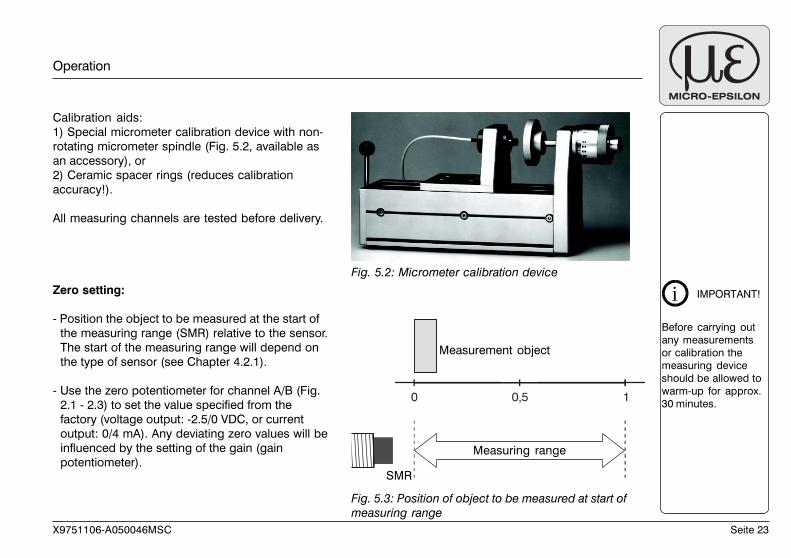
Calibration aids:
1) Special micrometer calibration device with non-
rotating micrometer spindle (Fig. 5.2, available as
an accessory), or
2) Ceramic spacer rings (reduces calibration
accuracy!).
All measuring channels are tested before delivery.
Zero setting:
- Position the object to be measured at the start of
the measuring range (SMR) relative to the sensor.
The start of the measuring range will depend on
the type of sensor (see Chapter 4.2.1).
- Use the zero potentiometer for channel A/B (Fig.
2.1 - 2.3) to set the value specified from the
factory (voltage output: -2.5/0 VDC, or current
output: 0/4 mA). Any deviating zero values will be
influenced by the setting of the gain (gain
potentiometer).
Fig. 5.2: Micrometer calibration device
Fig. 5.3: Position of object to be measured at start of
measuring range
SMR
0 0,5 1
Measuring range
Measurement object
i IMPORTANT!
Before carrying out
any measurements
or calibration the
measuring device
should be allowed to
warm-up for approx.
30 minutes.
Seite 24 X9751106-A050046MSC
Gain setting:
- Position the object to be measured at the end of
the measuring range (SMR) relative to the
sensor.
- Use the gain potentiometer for channel A/B
(Fig. 2.1 - 2.3) to set the desired value for the
output voltage/current. The maximum output
voltage cannot be set any higher than the
maximum output voltage set at the factory.
If required, repeat the steps for zero/gain until the
desired output characteristics have been
achieved.
5.2 Differential system DT3703
Installation alternatives for the sensors
Sensor A measures the distance to the object to be
measured.
Sensor B is set to a fixed reference distance.
Advantages: If the object to be measured and the
control object have virtually identical temperatures
and they are both at approx. the same distance
from sensor A or sensor B, temperature
compensation will be improved.
Fig. 5.4 Position of object to be measured at the end
of measuring range
0 0,5 1
SMR
Measuring range
Measuring object
Installation alternative 1
Operation
SMR EMR
Measuring range
Sensor A
Sensor B
Control
object
X9751106-A050046MSC Seite 25
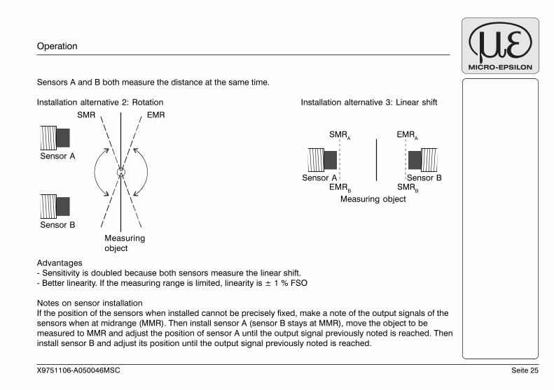
Sensors A and B both measure the distance at the same time.
Installation alternative 2: Rotation Installation alternative 3: Linear shift
Advantages
- Sensitivity is doubled because both sensors measure the linear shift.
- Better linearity. If the measuring range is limited, linearity is ± 1 % FSO
Notes on sensor installation
If the position of the sensors when installed cannot be precisely fixed, make a note of the output signals of the
sensors when at midrange (MMR). Then install sensor A (sensor B stays at MMR), move the object to be
measured to MMR and adjust the position of sensor A until the output signal previously noted is reached. Then
install sensor B and adjust its position until the output signal previously noted is reached.
Operation
Measuring
object
SMR EMR
Sensor A
Sensor B
SMRA
EMRA
Sensor A Sensor B
Measuring object
EMRB
SMRB
Seite 26 X9751106-A050046MSC
Warranty
6. Warranty
All components of the system have been checked and tested for perfect function in the factory.
In the unlikely event that errors should occur despite our thorough quality control, this should be reported
immediately to MICRO-EPSILON.
The warranty period lasts 12 months following the day of shipment. Defective parts, except wear parts, will be
repaired or replaced free of charge within this period if you return the device free of cost to MICRO-EPSILON.
This warranty does not apply to damage resulting from abuse of the equipment, from forceful handling or
installation of the devices or from repair or modifications performed by third parties.
Repairs must be exclusively done by MICRO-EPSILON.
No other claims, except as warranteed, are accepted. The terms of the purchasing contract apply in full.
MICRO-EPSILON will specifically not be responsible for eventual consequential damage.
MICRO-EPSILON always strives to supply it’s customers with the finest and most advanced equipment.
Development and refinement is therefore performed continuously and the right to design changes without
prior notice is accordingly reserved.
For translations in other languages, the data and statements in the German language operation manual are
to be taken as authoritative.
X9751106-A050046MSC Seite 27
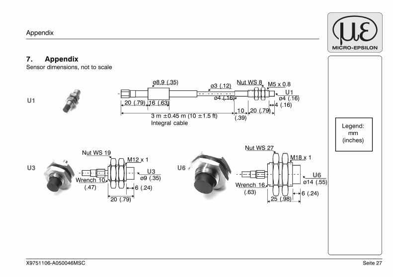
7. AppendixSensor dimensions, not to scale
Appendix
Legend:
mm
(inches)
U3
U1
U1
U6
U3 U6
20 (.79)
3 m ±0.45 m (10 ±1.5 ft)
Integral cable
16 (.63)
ø3 (.12) M5 x 0.8
ø4 (.16)
10
(.39)
20 (.79)4 (.16)
ø4 (.16)
ø8.9 (.35) Nut WS 8
M12 x 1
Wrench 10
(.47)
20 (.79)
ø9 (.35)
Nut WS 19
6 (.24)
M18 x 1
Wrench 16
(.63)25 (.98)
Nut WS 27
6 (.24)
ø14 (.55)
Seite 28 X9751106-A050046MSC
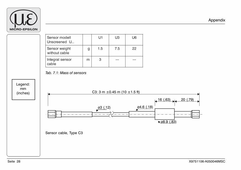
lledomrosneS
...UdeneercsnU
1U 3U 6U
thgiewrosneS
elbactuohtiw
g 5.1 5.7 22
rosneslargetnI
elbac
m 3 --- ---
Tab. 7.1: Mass of sensors
Appendix
Legend:
mm
(inches)
Sensor cable, Type C3
C3: 3 m ±0.45 m (10 ±1.5 ft)
ø3 (.12) ø4.6 (.18)
ø8.9 (.83)
20 (.79)16 (.63)