Embed Size (px)
Citation preview

SSeennssoorrss && TTrraannssdduucceerrss
Volume 132, Issue 9, September 2011
www.sensorsportal.com ISSN 1726-5479
Editors-in-Chief: professor Sergey Y. Yurish, tel.: +34 696067716, e-mail: [email protected]
Editors for Western Europe Meijer, Gerard C.M., Delft University of Technology, The Netherlands Ferrari, Vittorio, Universitá di Brescia, Italy
Editor South America Costa-Felix, Rodrigo, Inmetro, Brazil
Editor for Eastern Europe Sachenko, Anatoly, Ternopil State Economic University, Ukraine
Editors for North America Datskos, Panos G., Oak Ridge National Laboratory, USA Fabien, J. Josse, Marquette University, USA Katz, Evgeny, Clarkson University, USA
Editor for Asia Ohyama, Shinji, Tokyo Institute of Technology, Japan
Editor for Asia-Pacific Mukhopadhyay, Subhas, Massey University, New Zealand
Editorial Advisory Board
Abdul Rahim, Ruzairi, Universiti Teknologi, Malaysia Ahmad, Mohd Noor, Nothern University of Engineering, Malaysia Annamalai, Karthigeyan, National Institute of Advanced Industrial Science
and Technology, Japan Arcega, Francisco, University of Zaragoza, Spain Arguel, Philippe, CNRS, France Ahn, Jae-Pyoung, Korea Institute of Science and Technology, Korea Arndt, Michael, Robert Bosch GmbH, Germany Ascoli, Giorgio, George Mason University, USA Atalay, Selcuk, Inonu University, Turkey Atghiaee, Ahmad, University of Tehran, Iran Augutis, Vygantas, Kaunas University of Technology, Lithuania Avachit, Patil Lalchand, North Maharashtra University, India Ayesh, Aladdin, De Montfort University, UK Azamimi, Azian binti Abdullah, Universiti Malaysia Perlis, Malaysia Bahreyni, Behraad, University of Manitoba, Canada Baliga, Shankar, B., General Monitors Transnational, USA Baoxian, Ye, Zhengzhou University, China Barford, Lee, Agilent Laboratories, USA Barlingay, Ravindra, RF Arrays Systems, India Basu, Sukumar, Jadavpur University, India Beck, Stephen, University of Sheffield, UK Ben Bouzid, Sihem, Institut National de Recherche Scientifique, Tunisia Benachaiba, Chellali, Universitaire de Bechar, Algeria Binnie, T. David, Napier University, UK Bischoff, Gerlinde, Inst. Analytical Chemistry, Germany Bodas, Dhananjay, IMTEK, Germany Borges Carval, Nuno, Universidade de Aveiro, Portugal Bousbia-Salah, Mounir, University of Annaba, Algeria Bouvet, Marcel, CNRS – UPMC, France Brudzewski, Kazimierz, Warsaw University of Technology, Poland Cai, Chenxin, Nanjing Normal University, China Cai, Qingyun, Hunan University, China Campanella, Luigi, University La Sapienza, Italy Carvalho, Vitor, Minho University, Portugal Cecelja, Franjo, Brunel University, London, UK Cerda Belmonte, Judith, Imperial College London, UK Chakrabarty, Chandan Kumar, Universiti Tenaga Nasional, Malaysia Chakravorty, Dipankar, Association for the Cultivation of Science, India Changhai, Ru, Harbin Engineering University, China Chaudhari, Gajanan, Shri Shivaji Science College, India Chavali, Murthy, N.I. Center for Higher Education, (N.I. University), India Chen, Jiming, Zhejiang University, China Chen, Rongshun, National Tsing Hua University, Taiwan Cheng, Kuo-Sheng, National Cheng Kung University, Taiwan Chiang, Jeffrey (Cheng-Ta), Industrial Technol. Research Institute, Taiwan Chiriac, Horia, National Institute of Research and Development, Romania Chowdhuri, Arijit, University of Delhi, India Chung, Wen-Yaw, Chung Yuan Christian University, Taiwan Corres, Jesus, Universidad Publica de Navarra, Spain Cortes, Camilo A., Universidad Nacional de Colombia, Colombia Courtois, Christian, Universite de Valenciennes, France Cusano, Andrea, University of Sannio, Italy D'Amico, Arnaldo, Università di Tor Vergata, Italy De Stefano, Luca, Institute for Microelectronics and Microsystem, Italy Deshmukh, Kiran, Shri Shivaji Mahavidyalaya, Barshi, India Dickert, Franz L., Vienna University, Austria Dieguez, Angel, University of Barcelona, Spain Dighavkar, C. G., M.G. Vidyamandir’s L. V.H. College, India Dimitropoulos, Panos, University of Thessaly, Greece Ding, Jianning, Jiangsu Polytechnic University, China Djordjevich, Alexandar, City University of Hong Kong, Hong Kong
Donato, Nicola, University of Messina, Italy Donato, Patricio, Universidad de Mar del Plata, Argentina Dong, Feng, Tianjin University, China Drljaca, Predrag, Instersema Sensoric SA, Switzerland Dubey, Venketesh, Bournemouth University, UK Enderle, Stefan, Univ.of Ulm and KTB Mechatronics GmbH, Germany Erdem, Gursan K. Arzum, Ege University, Turkey Erkmen, Aydan M., Middle East Technical University, Turkey Estelle, Patrice, Insa Rennes, France Estrada, Horacio, University of North Carolina, USA Faiz, Adil, INSA Lyon, France Fericean, Sorin, Balluff GmbH, Germany Fernandes, Joana M., University of Porto, Portugal Francioso, Luca, CNR-IMM Institute for Microelectronics and Microsystems, Italy Francis, Laurent, University Catholique de Louvain, Belgium Fu, Weiling, South-Western Hospital, Chongqing, China Gaura, Elena, Coventry University, UK Geng, Yanfeng, China University of Petroleum, China Gole, James, Georgia Institute of Technology, USA Gong, Hao, National University of Singapore, Singapore Gonzalez de la Rosa, Juan Jose, University of Cadiz, Spain Granel, Annette, Goteborg University, Sweden Graff, Mason, The University of Texas at Arlington, USA Guan, Shan, Eastman Kodak, USA Guillet, Bruno, University of Caen, France Guo, Zhen, New Jersey Institute of Technology, USA Gupta, Narendra Kumar, Napier University, UK Habib, Maki K., American University in Cairo, Egypt Hadjiloucas, Sillas, The University of Reading, UK Haider, Mohammad R., Sonoma State University, USA Hashsham, Syed, Michigan State University, USA Hasni, Abdelhafid, Bechar University, Algeria Hernandez, Alvaro, University of Alcala, Spain Hernandez, Wilmar, Universidad Politecnica de Madrid, Spain Homentcovschi, Dorel, SUNY Binghamton, USA Horstman, Tom, U.S. Automation Group, LLC, USA Hsiai, Tzung (John), University of Southern California, USA Huang, Jeng-Sheng, Chung Yuan Christian University, Taiwan Huang, Star, National Tsing Hua University, Taiwan Huang, Wei, PSG Design Center, USA Hui, David, University of New Orleans, USA Jaffrezic-Renault, Nicole, Ecole Centrale de Lyon, France Jaime Calvo-Galleg, Jaime, Universidad de Salamanca, Spain James, Daniel, Griffith University, Australia Janting, Jakob, DELTA Danish Electronics, Denmark Jiang, Liudi, University of Southampton, UK Jiang, Wei, University of Virginia, USA Jiao, Zheng, Shanghai University, China John, Joachim, IMEC, Belgium Kalach, Andrew, Voronezh Institute of Ministry of Interior, Russia Kang, Moonho, Sunmoon University, Korea South Kaniusas, Eugenijus, Vienna University of Technology, Austria Katake, Anup, Texas A&M University, USA Kausel, Wilfried, University of Music, Vienna, Austria Kavasoglu, Nese, Mugla University, Turkey Ke, Cathy, Tyndall National Institute, Ireland Khelfaoui, Rachid, Université de Bechar, Algeria Khan, Asif, Aligarh Muslim University, Aligarh, India Kim, Min Young, Kyungpook National University, Korea South Ko, Sang Choon, Electronics. and Telecom. Research Inst., Korea South Kotulska, Malgorzata, Wroclaw University of Technology, Poland Kockar, Hakan, Balikesir University, Turkey

Kong, Ing, RMIT University, Australia Kratz, Henrik, Uppsala University, Sweden Krishnamoorthy, Ganesh, University of Texas at Austin, USA Kumar, Arun, University of South Florida, USA Kumar, Subodh, National Physical Laboratory, India Kung, Chih-Hsien, Chang-Jung Christian University, Taiwan Lacnjevac, Caslav, University of Belgrade, Serbia Lay-Ekuakille, Aime, University of Lecce, Italy Lee, Jang Myung, Pusan National University, Korea South Lee, Jun Su, Amkor Technology, Inc. South Korea Lei, Hua, National Starch and Chemical Company, USA Li, Genxi, Nanjing University, China Li, Hui, Shanghai Jiaotong University, China Li, Xian-Fang, Central South University, China Li, Yuefa, Wayne State University, USA Liang, Yuanchang, University of Washington, USA Liawruangrath, Saisunee, Chiang Mai University, Thailand Liew, Kim Meow, City University of Hong Kong, Hong Kong Lin, Hermann, National Kaohsiung University, Taiwan Lin, Paul, Cleveland State University, USA Linderholm, Pontus, EPFL - Microsystems Laboratory, Switzerland Liu, Aihua, University of Oklahoma, USA Liu Changgeng, Louisiana State University, USA Liu, Cheng-Hsien, National Tsing Hua University, Taiwan Liu, Songqin, Southeast University, China Lodeiro, Carlos, University of Vigo, Spain Lorenzo, Maria Encarnacio, Universidad Autonoma de Madrid, Spain Lukaszewicz, Jerzy Pawel, Nicholas Copernicus University, Poland Ma, Zhanfang, Northeast Normal University, China Majstorovic, Vidosav, University of Belgrade, Serbia Malyshev, V.V., National Research Centre ‘Kurchatov Institute’, Russia Marquez, Alfredo, Centro de Investigacion en Materiales Avanzados, Mexico Matay, Ladislav, Slovak Academy of Sciences, Slovakia Mathur, Prafull, National Physical Laboratory, India Maurya, D.K., Institute of Materials Research and Engineering, Singapore Mekid, Samir, University of Manchester, UK Melnyk, Ivan, Photon Control Inc., Canada Mendes, Paulo, University of Minho, Portugal Mennell, Julie, Northumbria University, UK Mi, Bin, Boston Scientific Corporation, USA Minas, Graca, University of Minho, Portugal Moghavvemi, Mahmoud, University of Malaya, Malaysia Mohammadi, Mohammad-Reza, University of Cambridge, UK Molina Flores, Esteban, Benemérita Universidad Autónoma de Puebla,
Mexico Moradi, Majid, University of Kerman, Iran Morello, Rosario, University "Mediterranea" of Reggio Calabria, Italy Mounir, Ben Ali, University of Sousse, Tunisia Mulla, Imtiaz Sirajuddin, National Chemical Laboratory, Pune, India Nabok, Aleksey, Sheffield Hallam University, UK Neelamegam, Periasamy, Sastra Deemed University, India Neshkova, Milka, Bulgarian Academy of Sciences, Bulgaria Oberhammer, Joachim, Royal Institute of Technology, Sweden Ould Lahoucine, Cherif, University of Guelma, Algeria Pamidighanta, Sayanu, Bharat Electronics Limited (BEL), India Pan, Jisheng, Institute of Materials Research & Engineering, Singapore Park, Joon-Shik, Korea Electronics Technology Institute, Korea South Penza, Michele, ENEA C.R., Italy Pereira, Jose Miguel, Instituto Politecnico de Setebal, Portugal Petsev, Dimiter, University of New Mexico, USA Pogacnik, Lea, University of Ljubljana, Slovenia Post, Michael, National Research Council, Canada Prance, Robert, University of Sussex, UK Prasad, Ambika, Gulbarga University, India Prateepasen, Asa, Kingmoungut's University of Technology, Thailand Pullini, Daniele, Centro Ricerche FIAT, Italy Pumera, Martin, National Institute for Materials Science, Japan Radhakrishnan, S. National Chemical Laboratory, Pune, India Rajanna, K., Indian Institute of Science, India Ramadan, Qasem, Institute of Microelectronics, Singapore Rao, Basuthkar, Tata Inst. of Fundamental Research, India Raoof, Kosai, Joseph Fourier University of Grenoble, France Rastogi Shiva, K. University of Idaho, USA Reig, Candid, University of Valencia, Spain Restivo, Maria Teresa, University of Porto, Portugal Robert, Michel, University Henri Poincare, France Rezazadeh, Ghader, Urmia University, Iran Royo, Santiago, Universitat Politecnica de Catalunya, Spain Rodriguez, Angel, Universidad Politecnica de Cataluna, Spain Rothberg, Steve, Loughborough University, UK Sadana, Ajit, University of Mississippi, USA Sadeghian Marnani, Hamed, TU Delft, The Netherlands Sandacci, Serghei, Sensor Technology Ltd., UK Sapozhnikova, Ksenia, D.I.Mendeleyev Institute for Metrology, Russia Saxena, Vibha, Bhbha Atomic Research Centre, Mumbai, India
Schneider, John K., Ultra-Scan Corporation, USA Sengupta, Deepak, Advance Bio-Photonics, India Seif, Selemani, Alabama A & M University, USA Seifter, Achim, Los Alamos National Laboratory, USA Shah, Kriyang, La Trobe University, Australia Silva Girao, Pedro, Technical University of Lisbon, Portugal Singh, V. R., National Physical Laboratory, India Slomovitz, Daniel, UTE, Uruguay Smith, Martin, Open University, UK Soleymanpour, Ahmad, Damghan Basic Science University, Iran Somani, Prakash R., Centre for Materials for Electronics Technol., India Srinivas, Talabattula, Indian Institute of Science, Bangalore, India Srivastava, Arvind K., NanoSonix Inc., USA Stefan-van Staden, Raluca-Ioana, University of Pretoria, South Africa Stefanescu, Dan Mihai, Romanian Measurement Society, Romania Sumriddetchka, Sarun, National Electronics and Computer Technology Center,
Thailand Sun, Chengliang, Polytechnic University, Hong-Kong Sun, Dongming, Jilin University, China Sun, Junhua, Beijing University of Aeronautics and Astronautics, China Sun, Zhiqiang, Central South University, China Suri, C. Raman, Institute of Microbial Technology, India Sysoev, Victor, Saratov State Technical University, Russia Szewczyk, Roman, Industrial Research Inst. for Automation and Measurement,
Poland Tan, Ooi Kiang, Nanyang Technological University, Singapore, Tang, Dianping, Southwest University, China Tang, Jaw-Luen, National Chung Cheng University, Taiwan Teker, Kasif, Frostburg State University, USA Thirunavukkarasu, I., Manipal University Karnataka, India Thumbavanam Pad, Kartik, Carnegie Mellon University, USA Tian, Gui Yun, University of Newcastle, UK Tsiantos, Vassilios, Technological Educational Institute of Kaval, Greece Tsigara, Anna, National Hellenic Research Foundation, Greece Twomey, Karen, University College Cork, Ireland Valente, Antonio, University, Vila Real, - U.T.A.D., Portugal Vanga, Raghav Rao, Summit Technology Services, Inc., USA Vaseashta, Ashok, Marshall University, USA Vazquez, Carmen, Carlos III University in Madrid, Spain Vieira, Manuela, Instituto Superior de Engenharia de Lisboa, Portugal Vigna, Benedetto, STMicroelectronics, Italy Vrba, Radimir, Brno University of Technology, Czech Republic Wandelt, Barbara, Technical University of Lodz, Poland Wang, Jiangping, Xi'an Shiyou University, China Wang, Kedong, Beihang University, China Wang, Liang, Pacific Northwest National Laboratory, USA Wang, Mi, University of Leeds, UK Wang, Shinn-Fwu, Ching Yun University, Taiwan Wang, Wei-Chih, University of Washington, USA Wang, Wensheng, University of Pennsylvania, USA Watson, Steven, Center for NanoSpace Technologies Inc., USA Weiping, Yan, Dalian University of Technology, China Wells, Stephen, Southern Company Services, USA Wolkenberg, Andrzej, Institute of Electron Technology, Poland Woods, R. Clive, Louisiana State University, USA Wu, DerHo, National Pingtung Univ. of Science and Technology, Taiwan Wu, Zhaoyang, Hunan University, China Xiu Tao, Ge, Chuzhou University, China Xu, Lisheng, The Chinese University of Hong Kong, Hong Kong Xu, Sen, Drexel University, USA Xu, Tao, University of California, Irvine, USA Yang, Dongfang, National Research Council, Canada Yang, Shuang-Hua, Loughborough University, UK Yang, Wuqiang, The University of Manchester, UK Yang, Xiaoling, University of Georgia, Athens, GA, USA Yaping Dan, Harvard University, USA Ymeti, Aurel, University of Twente, Netherland Yong Zhao, Northeastern University, China Yu, Haihu, Wuhan University of Technology, China Yuan, Yong, Massey University, New Zealand Yufera Garcia, Alberto, Seville University, Spain Zakaria, Zulkarnay, University Malaysia Perlis, Malaysia Zagnoni, Michele, University of Southampton, UK Zamani, Cyrus, Universitat de Barcelona, Spain Zeni, Luigi, Second University of Naples, Italy Zhang, Minglong, Shanghai University, China Zhang, Qintao, University of California at Berkeley, USA Zhang, Weiping, Shanghai Jiao Tong University, China Zhang, Wenming, Shanghai Jiao Tong University, China Zhang, Xueji, World Precision Instruments, Inc., USA Zhong, Haoxiang, Henan Normal University, China Zhu, Qing, Fujifilm Dimatix, Inc., USA Zorzano, Luis, Universidad de La Rioja, Spain Zourob, Mohammed, University of Cambridge, UK
Sensors & Transducers Journal (ISSN 1726-5479) is a peer review international journal published monthly online by International Frequency Sensor Association (IFSA). Available in electronic and on CD. Copyright © 2011 by International Frequency Sensor Association. All rights reserved.

SSeennssoorrss && TTrraannssdduucceerrss JJoouurrnnaall
CCoonntteennttss
Volume 132 Issue 9 September 2011
www.sensorsportal.com ISSN 1726-5479
Research Articles
Gas Sensors Based on Inorganic Materials: An Overview K. R. Nemade ..................................................................................................................................... 1 Control Valve Stiction Identification, Modelling, Quantification and Control - A Review Srinivasan Arumugam and Rames C. Panda..................................................................................... 14 Numerical Prediction of a Bi-Directional Micro Thermal Flow Sensors M. Al-Amayrah, A. Al-Salaymeh, M. Kilani, A. Delgado ..................................................................... 25 The Linearity of Optical Tomography: Sensor Model and Experimental Verification Siti Zarina Mohd. Muji, Ruzairi Abdul Rahim, Mohd Hafiz Fazalul Rahiman, Zulkarnay Zakaria, Elmy Johana Mohamad, Mohd Safirin Karis ...................................................................................... 40 Structure Improvement and Simulation Research of a Three-dimensional Force Flexible Tactile Sensor Based on Conductive Rubber Shanhong Li, Xuekun Zhuang, Fei Xu, Junxiang Ding, Feng Shuang, Yunjian Ge...................................................... 47 Modeling and Simulation of Wet Gas Flow in Venturi Flow Meter Hossein Seraj, Mohd Fuaad Rahmat, Marzuki Khaled, Rubiyah Yusof and Iliya Tizhe Thuku ......... 57 Improvement Study of Wet Nitrocellulose Membranes Using Optical Reflectometry Hariyadi Soetedjo ............................................................................................................................... 69 Use of Balance Calibration Certificate to Calculate the Errors of Indication and Measurement Uncertainty in Mass Determinations Performed in Medical Laboratories Adriana Vâlcu ..................................................................................................................................... 76 Improved Web-based Power Quality Monitoring Instrument I. Adam, A. Mohamed and H. Sanusi ................................................................................................. 89 Design and Fabrication of a Soil Moisture Meter Using Thermal Conductivity Properties of Soil Subir Das, Biplab Bag, T. S. Sarkar, Nisher Ahmed, B. Chakrabrty .................................................. 100 Numerical Study of Mechanical Stirring in Case of Yield Stress Fluid with Circular Anchor Impeller Brahim Mebarki, Belkacem Draoui, Lakhdar Rahmani, Mohamed Bouanini, Mebrouk Rebhi, El hadj Benachour .............................................................................................................................. 108 Computer Vision Based Smart Lane Departure warning System for Vehicle Dynamics Control Ambarish G. Mohapatra ..................................................................................................................... 122

Simple Implementation of an Electronic Tongue for Taste Assessments of Food and Beverage Products Abdul Hallis Abdul Aziz, Ali Yeon Md. Shakaff, Rohani Farook, Abdul Hamid Adom, Mohd Noor Ahmad and Nor Idayu Mahat........................................................................................... 136 Aluminum-Selective Electrode Based on (1E,2E)-N1,N2- dihydroxy )-N1,N2- bis (4-hydroxy phenyl) Oxalimidamide as a Neutral Carrier Aghaie M., Esfandyar Baghdar, Fekri Lari F., Ali Kakanejadifard, Aghaie H. .................................... 151
Authors are encouraged to submit article in MS Word (doc) and Acrobat (pdf) formats by e-mail: [email protected] Please visit journal’s webpage with preparation instructions: http://www.sensorsportal.com/HTML/DIGEST/Submition.htm
International Frequency Sensor Association (IFSA).


Sensors & Transducers Journal, Vol. 132, Issue 9, September 2011, pp. 25-39
25
SSSeeennnsssooorrrsss &&& TTTrrraaannnsssddduuuccceeerrrsss
ISSN 1726-5479© 2011 by IFSA
http://www.sensorsportal.com
Numerical Prediction of a Bi-Directional Micro Thermal Flow Sensors
a M. Al-Amayrah, a, b A. Al-Salaymeh, b M. Kilani, a A. Delgado
a Lehrstuhl für Strömungsmechanik, Friedrich-Alexander-Universität Erlangen-Nürnberg, Cauerstr. 4, 91058 Erlangen, Germany
Fax: +49-9131-8529503 b Mechanical Engineering Department, The University of Jordan, Amman 11942, Jordan
E-mail: [email protected], [email protected], [email protected], [email protected], [email protected]
Received: 26 July 2011 /Accepted: 19 September 2011 /Published: 27 September 2011 Abstract: Thermal flow sensors such as hot-wire anemometer (HWA) can be used to measure the flow velocity with certain accuracy. However, HWA can measure the flow velocity without determining the flow direction. Pulsed-Wire Anemometer (PWA) with 3 wires can be used to measure flow velocity and flow directions. The present study aims to develop a numerical analysis of unsteady flow around a pulsed hot-wire anemometer using three parallel wires. The pulsed wire which is called the heated wire is located in the middle and the two sensor wires are installed upstream and downstream of the pulsed wire. 2-D numerical models were built and simulated using different wires arrangements. The ratio of the separation distance between the heated wire and sensor wire (x) to the diameter of the heated wire (D) ratios (x/D) was varied between 3.33 and 183.33. The output results are plotted as a function of Peclet number (convection time / diffusion time). It was found that as the ratio of x/D increases, the sensitivity of PWA device to the time of flight decreases. But at the same the reading of the time of flight becomes more accurate, because the effects of the diffusion and wake after the heated wire decrease. Also, a very good agreement has been obtained between the present numerical simulation and the previous experimental data. Copyright © 2011 IFSA. Keywords: Pulsed wire anemometer (PWA), Hot-wire Anemometer (HWA), Bi-Directional sensor, three parallel wires, Numerical prediction.

Sensors & Transducers Journal, Vol. 132, Issue 9, September 2011, pp. 25-39
26
Nomenclature
Pc Specific heat at constant pressure, J ( k g C )
D Heated wire diameter, m sD Sensor wire diameter, m
f Frequency, Hz g Gravitational acceleration, m2/s
k Thermal conductivity, W (m C) p Pressure, Pa T Temperature, K
staT The sending temperature average, K
max,rT
The maximum value of the received temperature, K
min,rT The minimum value of the received temperature, K
t Time, s U Free stream velocity, m/s
iu
Cartesian velocity components where u1 = u and u2 = v
ix Cartesian coordinates (x, y)
X Distance between the heated wire and the sensor wire, mm Greek Symbols ø Time of flight, s
ρ Fluid density, kg/m3 1 ( )T T
α Thermal diffusivity of the fluid, m2/s μ Dynamic viscosity, N.s/m2
ψ The angle between the direction normal to the plane of the probe and the instantaneous velocity vector
The viscous dissipation function given by j
,j i i
i j
u u u
x x x
Non-dimensional Numbers Pe Peclet number, Pe Re Pr U X
Pr Prandtl number, Disspation heat
PrConduction heat
,
p
f
c
k
Re Reynolds number, Inertia forces
ReViscous forces
w
f
U d
DGr Grashof number, 3
2
( )Buoyancy forces
Viscous forcesw
D
g D T TGr
Ec Eckert number 2Kinatic energy
Ec= ;Enthalpy ( )p w
U
c T T

Sensors & Transducers Journal, Vol. 132, Issue 9, September 2011, pp. 25-39
27
1. Introduction It is often desirable in flow studies and survey work to be able to measure the velocity of gases at points within the flow pattern inside both pipes and open channels to determine either mean velocity or flow profile. The most common techniques used in such measurements are the Laser-Doppler Anemometer (LDA), Hot-Wire Anemometer (HWA) and Pitot tube, e.g. Walt [1]. The pitot tube is suitable for high velocity measurements but becomes inaccurate for low velocity fields. In addition, it is used in one directional flow. The LDA uses the Doppler shift of light scattered by moving particles in the flow stream to determine particles velocity and hence fluid flow velocity. It is difficult to measure the flow velocity in regions near walls by using LDA because of the beam reflections. LDA needs high cost for production and is particularly suited to velocity studies in systems that would not allow the installation of a more conventional system, for example, around propellers and in turbines, e.g. Al-Salaymeh [2]. The hot-wire/film anemometer (HWA) method is widely used for flow studies in gases flows. It requires calibration and it can be produced at a low cost for Industrial applications. It has a fast response, small sizes and low noise, e.g. Chen [3]. Conventional HWA is assembled by mounting a thin wire, made of platinum or tungsten, on support prongs. The HWA even the ideal one is subjected to serious errors; this is due not only to the nonlinear response of this instrument to fluctuations in the magnitude of the velocity vector, but also to its ambiguous response to variations in the flow direction, e.g. Bradbury and Castro [4] and Castro [5]. The idea of Bi-directional hot wire anemometer came from PWA that usually consists of three wires; the middle wire is the heated wire which is located at right angles to the sensor wires to produce an instrument with a wide yaw response, e.g. Durst et al. [6]. This device measures the time shift between the sending and receiving temperature signals, and this time is called the Time-of-Flight (TOF), e.g. Durst et al. [7]. Al-Salaymeh et al. [8] described a pulsed hot wire anemometer that consists of three parallel hot wires; the heated wire in the middle and the two sensor wires on each side. The range of the measured velocity was varied between 0.05 < U< 25 m/s. In addition, the distance between the heated wire and the received wire was selected to be1.25 mm. They used sinusoidal signals for heating the pulsed wire. Bauer [9] used a PWA with square sending signal and the distance between the wires was selected to be 2.0 mm. Experimental investigations of the TOF of a tracer of heated air from an electrically pulsed wire to one of two sensor wires at right angles to the pulsed wire placed on either side of a pulsed wire was described Elliott et al. [10]. Kielbasa et al. [11] pointed out that the TOF depends not only on the flow velocity and the distance between the two wires, but also on some other parameters such as the wire time constants and the dynamic properties of the amplifier. TOF for slowly changing flows can be increased by using wires with large thermal inertia (time constant) and heating the sending wire with continuous sinusoidal current, instead of square-wave pulses, e.g. Al-Salaymeh [2]. At higher velocities, the TOF eventually becomes comparable to the decay time of the picked up signal, and the signal from the heat pulse merges into the decaying “tail” of the interference signal, e.g. Bradbury and Castro [4]. However, in the recent few years, the new micromachining process which was developed in the last decades encouraged the use of small physical size of the HWA for better performance, e.g. Breuer et al. [12]. Many experiments of the micro machined hot wire anemometers with the steady state characteristics, frequency response and directional dependence were reported, Jiang et al. [13]. Experimental studies of Jiang et al. [13] resulted a micro hot-wire model with 10 μm long, 1 μm wide and 0.5 μm thick where polysilicon was used as hot wire material. They developed trapezoidal cross section defined by cross section of the micro hot-wire instead of circular section. Al-Salaymeh and

Sensors & Transducers Journal, Vol. 132, Issue 9, September 2011, pp. 25-39
28
Ashhab [14] utilized the neural nets to model hot-wire thermal flow sensor under different operating conditions. Amayrah et al. [15] investigated numerically the micro HWA using three parallel wires. He calculated the TOF for a certain wires arrangements. The TOF depends on many physical parameters such as the properties of the fluid, the heated wire material, the separation distance between the heated and sensor wires, the diameters of each wire and the kind of boundary conditions (shear wall, the velocity, pressure and temperature at inlet and outlet). This study discusses the influence of separation distance ratio (X/D) and the free stream velocity on the sensitivity of the bi-directional thermal flow sensor. 2. Model Description The probe configuration for the micro thermal flow sensor which has been investigated in the present work is shown in Fig. 1a. It consists of three parallel wires and the length of each wire is several hundred times the diameter of the pulsed wire. The central wire is the heated wire and the other two wires are the sensor wires. The use of two sensor wires on either side of the heated wire would ensure that the direction of the flow at that instant could be unambiguously determined. If the heated wire connected with an AC current the temperature appears as a sinusoidal thermal signal. If the flow basses from left to right, the left sensor will record a constant temperature and the right sensor will
shows a thermal sinusoidal signal with a delay as appears in Fig.1b. The time of delay between the pulsed signal and the received signal consists of the time delay in the heated wire and the sensor wire due to the thermal inertia of the wires in addition to the time of flight.
(a) 3D Schematic of bi-directional micro hot-wire anemometer using three parallel wires.
(b) Explain of the pulsed hot wire anemometer work, main
parameters, coordinate and boundary conditions.
Fig. 1. Description of the model.
3. Mathematical Formulation 3.1. Thermal Inertia of the Heated and Sensor Wires The heat balance in the heated wire can be shown in Fig. 2. The heat generated inside the hot wire is balanced by radioactive heat to surrounding, convective heat to the fluid, accumulated heat inside the wire and conductive heat to the prongs of the finite wire, e.g. Bruun [16].
,U T T
left sensor wire Right sensor wire
T ( ) sin(2 )w t A B ft T ( , , ) sin(2 ( ))w t x y F D f t
The thermal wake
wT =T
0iu
0iu
0iu
Heated wire
Wall
0PP
Wall
Heated Wire Right Sensor Wire Tungsten
Left Sensor Wire Tungsten
L
Ds
Ds D

Sensors & Transducers Journal, Vol. 132, Issue 9, September 2011, pp. 25-39
29
2 24 4
2
stored
ww ww w w w w w w w w
wConvection HeatheatElectricalHeate conduction radiation
heat heat
IT Tc A d h T T k A d T T
t A z
(1)
where 42ww dA is the cross section area of the wire and the heat conduction to the support needles
is negligible. The length to the diameter ratio is large in our case 400/ dL . The heat radiation term is negligible less than 0.1% of the heat convection loss, e.g. Al-Salaymeh [17].
2
.( ) ( )
w ww a
w w w w w w w
T IDh T T
t c A A c A
(2)
A sinusoidal signal has been used to define the current. The electrical current has the form as: sin(2 )I A B ft (3) The heat transfer coefficient h can be calculated from the correlation equation of Nusselt number that described by Collis and Williams [18]. f
w
kh Nu
d
(4)
0.17
0.45Nu= 0.24 0.56Re fT
T
(5)
This equation can be used for Reynolds numbers up to about 45. The film temperature defined as:
2f wT T T .
Fig. 2. Heat balance of the heated wire.
Thermal energy balance for the receiving wire is that the stored energy in the sensor equals to the heating convection, i.e.:

Sensors & Transducers Journal, Vol. 132, Issue 9, September 2011, pp. 25-39
30
w
w w w f a w
dTc A Nu k T T
d t
(6)
Equation (6) could be written as:
( )ww a
dTM T T t
d t
, (7)
where M is the wire time constant and it can be written as: w w w
f
c AM
Nu k
(8)
Since the thermal conductivity and the kinematics viscosity are very sensitive to the temperature, the simulation in the present work considered the correlation equations of the Kannuluik et al. [19]: 2 2( ) 2.41 10 (1 0.00317 0.000002 )fk T T T (9.a) )000008.0009414.03349.1(10)( 25 TTTf
(9.b)
3.2. The Time of Flight In order to find the time of flight between the heated and sensor wires, the governing equations of the fluid flow and heat transfer around the heated wire and sensor wires should be solved. A two dimensional model has been solved with configuration shown in Fig. 1 (b). The distance between the heated wire and each of the sensor wire in both sides is equal. The flow enters from the left with a given flow velocity U, the upper wall is assumed to be far away from the heated wire. At outlet the gage pressure is assumed to be zero, i.e. similar to the atmospheric pressure. To solve the 2-D governing equations, the following dimensionless parameters have been used: * * *
1,2* *1,2 2
* * * *
,
( ); ;
( )
; ;
; ; ; ;pff p
f p
T Tx yx y T
D D Tw T
u Pu p
U U
ckk c
k c
(10)
The unsteady governing equations (continuity, momentum and energy equations) can be written in a dimensionless form after inserting the parameters shown in Eq. 10 to be as the following: Continuity equation:
0)(1
*
**
*
*
x
u
Stt
i
(11)
*2
P pP
U
t
t *
*
Sensors & Transducers Journal, Vol. 132, Issue 9, September 2011, pp. 25-39
31
Momentum equation
*2*
*
*
**
**
*
*
**
*
**
Re)(
Re
1T
Gr
x
u
x
u
xx
P
x
uu
t
uSt
D
D
j
i
i
j
iDji
ji
j
. (12)
Energy equation
**
**
**
***
*
***
ReRePr
1)(
D
c
iiDi
ip
E
x
Tk
xx
uT
t
TStc
, (13)
where i, j = 1, 2 for 2-D and * is the normalized viscous dissipation function which can be given by
* * *
** * *
* j i i
i j j
u u u
x x x
(14)
and
,P TT
or can be written in the form: 1 ( )T T
, (15)
where denotes the coefficient of thermal expansion at temperature T . The value of coefficient of thermal expansion explained in Schlichting [20] is given as: (1 / )1 1
PT T T T T
(16)
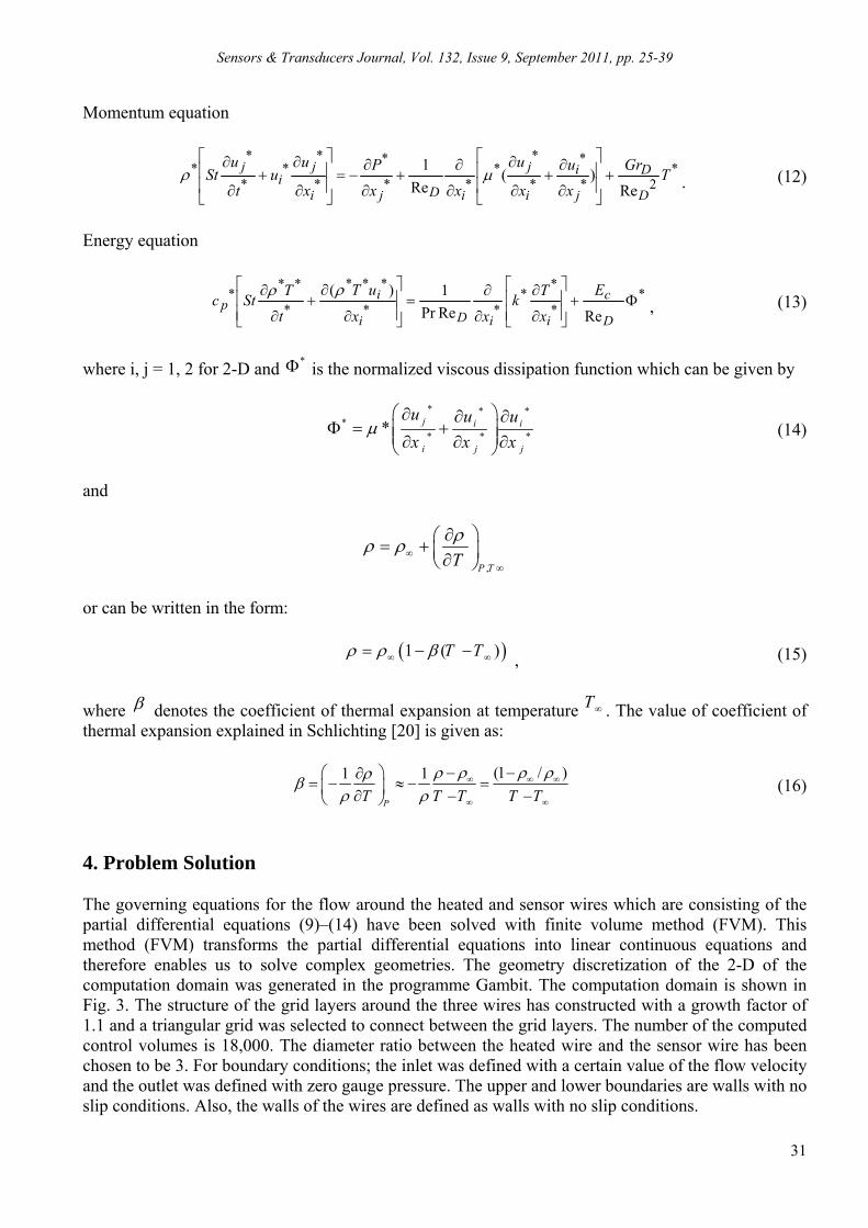
4. Problem Solution The governing equations for the flow around the heated and sensor wires which are consisting of the partial differential equations (9)–(14) have been solved with finite volume method (FVM). This method (FVM) transforms the partial differential equations into linear continuous equations and therefore enables us to solve complex geometries. The geometry discretization of the 2-D of the computation domain was generated in the programme Gambit. The computation domain is shown in Fig. 3. The structure of the grid layers around the three wires has constructed with a growth factor of 1.1 and a triangular grid was selected to connect between the grid layers. The number of the computed control volumes is 18,000. The diameter ratio between the heated wire and the sensor wire has been chosen to be 3. For boundary conditions; the inlet was defined with a certain value of the flow velocity and the outlet was defined with zero gauge pressure. The upper and lower boundaries are walls with no slip conditions. Also, the walls of the wires are defined as walls with no slip conditions.
Sensors & Transducers Journal, Vol. 132, Issue 9, September 2011, pp. 25-39
32
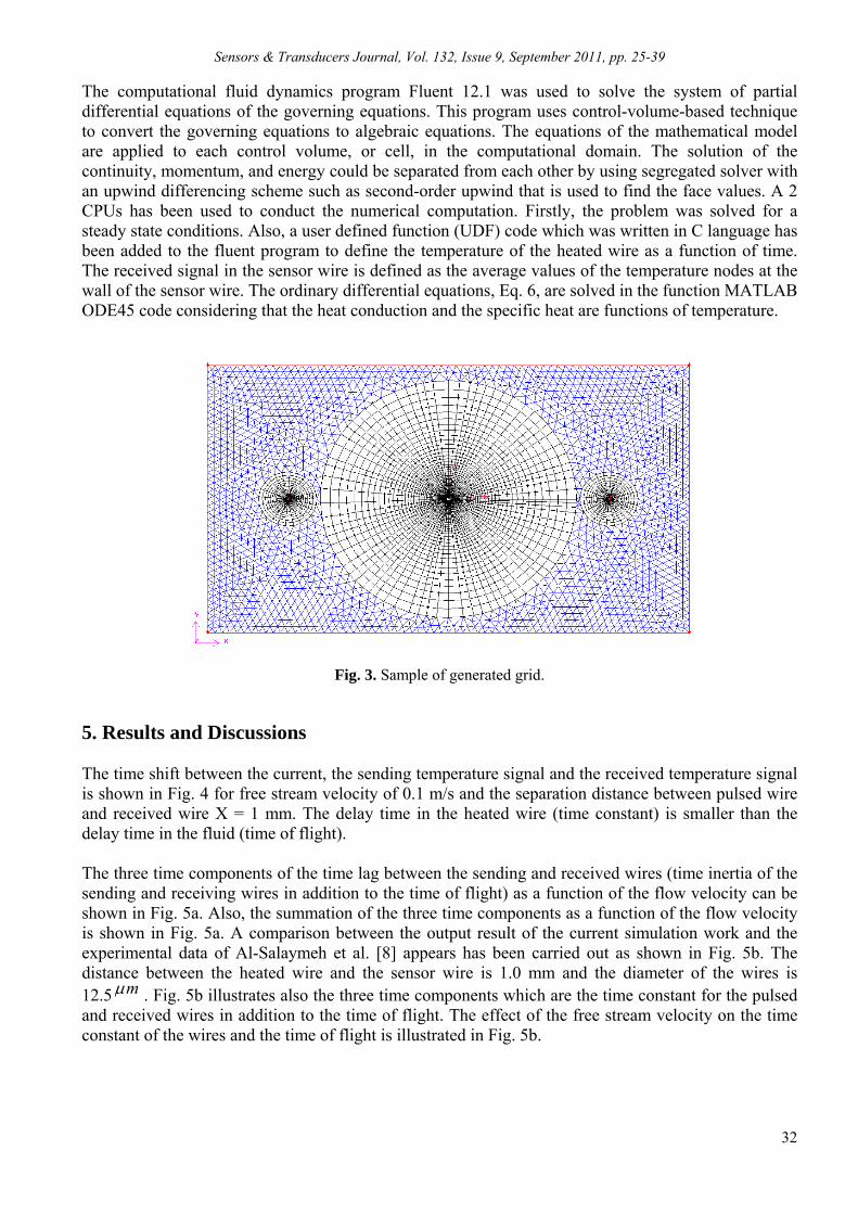
The computational fluid dynamics program Fluent 12.1 was used to solve the system of partial differential equations of the governing equations. This program uses control-volume-based technique to convert the governing equations to algebraic equations. The equations of the mathematical model are applied to each control volume, or cell, in the computational domain. The solution of the continuity, momentum, and energy could be separated from each other by using segregated solver with an upwind differencing scheme such as second-order upwind that is used to find the face values. A 2 CPUs has been used to conduct the numerical computation. Firstly, the problem was solved for a steady state conditions. Also, a user defined function (UDF) code which was written in C language has been added to the fluent program to define the temperature of the heated wire as a function of time. The received signal in the sensor wire is defined as the average values of the temperature nodes at the wall of the sensor wire. The ordinary differential equations, Eq. 6, are solved in the function MATLAB ODE45 code considering that the heat conduction and the specific heat are functions of temperature.
Fig. 3. Sample of generated grid.
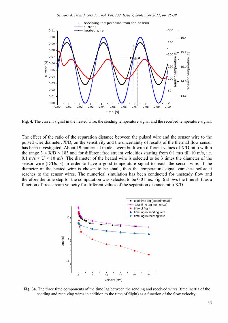
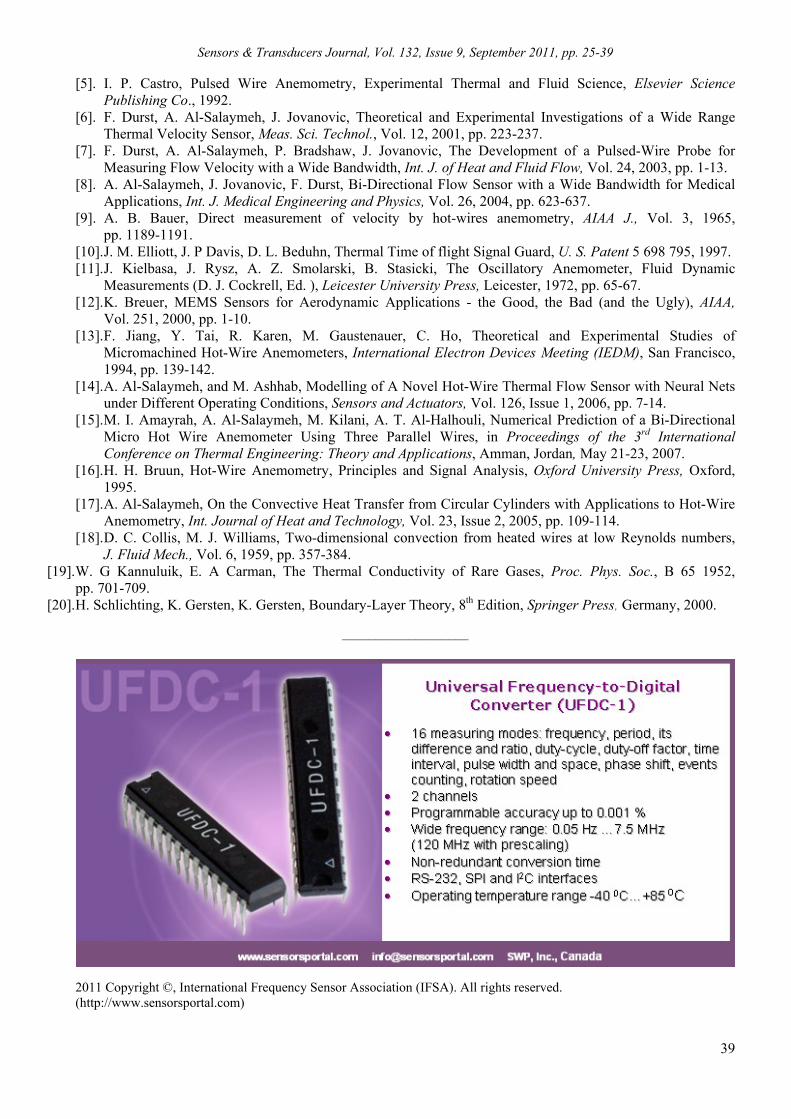
5. Results and Discussions The time shift between the current, the sending temperature signal and the received temperature signal is shown in Fig. 4 for free stream velocity of 0.1 m/s and the separation distance between pulsed wire and received wire X = 1 mm. The delay time in the heated wire (time constant) is smaller than the delay time in the fluid (time of flight). The three time components of the time lag between the sending and received wires (time inertia of the sending and receiving wires in addition to the time of flight) as a function of the flow velocity can be shown in Fig. 5a. Also, the summation of the three time components as a function of the flow velocity is shown in Fig. 5a. A comparison between the output result of the current simulation work and the experimental data of Al-Salaymeh et al. [8] appears has been carried out as shown in Fig. 5b. The distance between the heated wire and the sensor wire is 1.0 mm and the diameter of the wires is 12.5 m . Fig. 5b illustrates also the three time components which are the time constant for the pulsed and received wires in addition to the time of flight. The effect of the free stream velocity on the time constant of the wires and the time of flight is illustrated in Fig. 5b.
Sensors & Transducers Journal, Vol. 132, Issue 9, September 2011, pp. 25-39
33
0.00 0.01 0.02 0.03 0.04 0.05 0.06 0.07 0.08 0.09 0.100.00
0.01
0.02
0.03
0.04
0.05
0.06
0.07
0.08
0.09
0.10
0.11 current
curr
ent [
A]
time [s]
0
50
100
150
200
250
300
sen
din
g te
mpe
ratu
re [C
]
heated wire
14.6
14.8
15.0
15.2
15.4
rece
ivin
g te
mpe
ratu
re [C
]
receiving temperature from the sensor
Fig. 4. The current signal in the heated wire, the sending temperature signal and the received temperature signal. The effect of the ratio of the separation distance between the pulsed wire and the sensor wire to the pulsed wire diameter, X/D, on the sensitivity and the uncertainty of results of the thermal flow sensor has been investigated. About 19 numerical models were built with different values of X/D ratio within the range 3 < X/D < 183 and for different free stream velocities starting from 0.1 m/s till 10 m/s, i.e. 0.1 m/s < U < 10 m/s. The diameter of the heated wire is selected to be 3 times the diameter of the sensor wire (D/Ds=3) in order to have a good temperature signal to reach the sensor wire. If the diameter of the heated wire is chosen to be small, then the temperature signal vanishes before it reaches to the sensor wires. The numerical simulation has been conducted for unsteady flow and therefore the time step for the computation was selected to be 0.01 ms. Fig. 6 shows the time shift as a function of free stream velocity for different values of the separation distance ratio X/D.
0 5 10 15 20 25
0.1
1
10
time
[s]
velocity [m/s]
total time lag [experimental] total time lag [numerical] time of flighttime lag in sending wiretime lag in reciving wire
Fig. 5a. The three time components of the time lag between the sending and received wires (time inertia of the sending and receiving wires in addition to the time of flight) as a function of the flow velocity.

Sensors & Transducers Journal, Vol. 132, Issue 9, September 2011, pp. 25-39
34
0 5 10 15 20 25
5
10
15
20
25
30
Tim
e [s
]
Velocity [m/s]
Total time lag (experimental) Total time lag ( Numerical )
Fig. 5b. A comparison between the present numerical results and the experimental data of the total time lag at X = 1.2 mm and U=.01 m/s.
0,010
0,100
1,000
10,000
100,000
0,01 0,10 1,00 10,00
U (m/s)
Tim
e (m
s)
X/D=3.33
X/D=6.67
X/D=8.33
X/D=12.5
X/D=16.67
X/D=41.67
X/D=66.67
X/D=75
X/D=83.33
X/D=91.67
X/D=100
X/D=108.33
X/D=116.67
X/D=125
X/D=141.67
X/D=150
X/D=158.33
X/D=166.67
X/D=183.33
Fig. 6. The time lag between the heated and sensor wires as a function of free stream velocity for different ratios of separation distance X/D.
Figs. 7 (a-f) show the heated and received temperature signals at different values of the separation distance X and at a certain value of the flow velocity. It is clear from Figs. 7 (a-f) that as the flow velocity increases, the time shift between the sending and received temperature signal decreases, which makes it difficult to determine the time shift at high flow velocities. In addition, the amplitude of the temperature signal at the sensor wire decreases as the separation distance increase until it almost vanishes in case of X/D > 183.33. The influence of the wires separation distance on the strength of the received temperature signal can be shown in Fig. 8. The strength of the received temperature signal can be defined as:

Sensors & Transducers Journal, Vol. 132, Issue 9, September 2011, pp. 25-39
35
ratio max, min, sta T = /r rT T T, (17)
where max,rT and min,rT values are taken from Figs. 7 (a-f). Bradbury and Castro [4] explained that the
time of flight consist of two components; the diffusive time and the convection time which depends mainly on the velocity of the free-stream velocity and the separation distance ratio X/D, in other wards,
/c X U . At low flow velocity the diffusion method dominates the heat transfer and the value of
diffusion time is 2 /d X . The Peclet number (Pe) is used usually to show the influence of the
diffusion time on the convection time. The Peclet number could be defined as:
2
/ Time of convection ( ) Re.Pr
/ Time of diffusion
X UPeclet number Pe
X
(18)
From this equation, when 0Pe this means that there is no convection and there is pure diffusion. In contrast, as Pe , the convection time is dominant and the convection governs the fluid and heat with no diffusion.
450 455 460 465 470 475 480 485 490 495 500 505300
350
400
450
500
550
Time (ms)
Tem
pera
ture
(K
)
Sending temperatureX/D=3.33X/D=6.67X/D=8.33X/D=12.5X/D=16.67X/D=41.67X/D=66.67X/D=75X/D=83.33X/D=91.67X/D=100X/D=108.33X/D=116.67X/D=125X/D=141.67X/D=150X/D=158.33X/D=166.67
Fig. 7a. The sending and the received temperature signal at different values of X and U=0.01 m/s.
370 380 390 400 410 420 430
350
400
450
500
550
Time (ms)
Tem
pera
ture
(K
)
Sending TemperatureX/D=3.33X/D=6.67X/D=8.33X/D=12.5X/D=16.67X/D=41.67X/D=66.67X/D=75X/D=83.33X/D=91.67X/D=100X/D=108.33X/D=116.67X/D=125X/D=141.67X/D=150X/D=158.33X/D=166.67X/D=183.33
Fig. 7b. The sending and the received temperature signal at different values of X and U=0.1 m/s.

Sensors & Transducers Journal, Vol. 132, Issue 9, September 2011, pp. 25-39
36
330 340 350 360 370 380300
350
400
450
500
Time (ms)
Tem
pera
ture
(K
)
Sending temperatureX/D=3.33X/D=6.67X/D=8.33X/D=12.5X/D=16.67X/D=41.67X/D=66.67X/D=75X/D=83.33X/D=91.67X/D=100X/D=108.33X/D=116.67X/D=125X/D=141.67X/D=150X/D=158.33X/D=166.67X/D=183.33
Fig. 7c. The sending and the received temperature signal at different values of X and U=1 m/s.
230 240 250 260 270 280 290 300300
350
400
450
500
Time (ms)
Tem
pera
ture
(K
)
Sending temperatureX/D=3.33X/D=6.67X/D=8.33X/D=12.5X/D=16.67X/D=41.67X/D=66.67X/D=75X/D=83.33X/D=91.67X/D=100X/D=108.33X/D=116.67X/D=125X/D=141.67X/D=150X/D=158.33X/D=166.67X/D=183.33
Fig. 7d. The sending and the received temperature signal at different values of X and U=3 m/s.
245 250 255 260 265 270 275 280
300
350
400
450
500
Time (ms)
Tem
pera
ture
(K
)
Sending temperatureX/D=3.33X/D=6.67X/D=8.33X/D=12.5X/D=16.67X/D=41.67X/D=66.67X/D=75X/D=83.33X/D=91.67X/D=100X/D=108.33X/D=116.67X/D=125X/D=141.67X/D=150X/D=158.33X/D=166.67X/D=183.33
Fig. 7e. The sending and the received temperature signal at different values of X and U=5 m/s.

Sensors & Transducers Journal, Vol. 132, Issue 9, September 2011, pp. 25-39
37
340 345 350 355 360 365 370 375300
350
400
450
500
Time (ms)
Tem
pera
ture
(K
)
Sending temperatureX/D=3.33X/D=6.67X/D=8.33X/D=12.5X/D=16.67X/D=41.67X/D=66.67X/D=75X/D=83.33X/D=91.67X/D=100X/D=108.33X/D=116.67X/D=125X/D=141.67X/D=150X/D=158.33X/D=166.67X/D=183.33
Fig. 7f. The sending and the received temperature signal at different values of X and U= 10 m/s.
0
0,1
0,2
0,3
0,4
0,5
0 50 100 150 200X/D
(Tm
ax-T
min
)/T
sta
U=0.1 m/sU= 1 m/sU= 3 m/sU=5 m/sU=10 m/s
Fig. 8. The received temperature ratio as a function of the separation distance ratio X/D for different values of the free-stream velocity.
The uncertainty of the results and the sensitivity of HWA could be discussed in Fig. 9 which shows the position intercept /U X at different values of X/D ratio. The true value of the result should be at the position of intercept / 1.0U X .The uncertainty could be define as the deviation from this value. The sensitivity of the time-of-flight sensor at a certain Peclet number could be defined as the slope of the curve. For the ratio of X/D < 66.67, the reading of the phase shift (time shift) has a big uncertainty because the diffusion governs more than convection. However, the sensitivity is high in this region. When the ratio of X/D > 66.67, the results show a big uncertainty at low Peclet numbers and therefore the uncertainty becomes low at higher values of Peclet number. Any how, the sensitivity of HWA becomes very low at a high separation distance between the heated and received wires. 6. Conclusion This work has presented a numerical investigation for the behavior of bi-directional micro thermal flow sensors which utilizes three parallel wires. The goal of this study is to determine the effects of the sensor parameters such as the flow velocity U and aspect ratio X/D on the time shift between the heated and the sensor wire.

Sensors & Transducers Journal, Vol. 132, Issue 9, September 2011, pp. 25-39
38
0,000
0,500
1,000
1,500
2,000
2,500
3,000
0,01 0,10 1,00 10,00 100,00 1000,00
Peclet number
(U
)/X
X/D=3.333X/D=6.667X/D=8.333X/D=16.667X/D=66.667X/D=75X/D=83.333X/D=91.667X/D=100X/D=108.33X/D=116.667X/D=125X/D=141.667X/D=150X/D=158.33X/D=166.667X/D=183.33
Fig. 9. The position of intercept /U X as a function of the Peclet numbers for different values of X/D ratio and a certain value of diameter ratio D/Ds=3.
The effect of the aspect ratio X/D on the time of flight was investigated. Many numerical models were built using the ratio of the heated wire diameter to the sensor diameter / 3D Ds for the range of aspect ratios of 3.33 / 183.33X D . The frequency of the current in the heated wire was selected to be 30 Hz to prevent interface between the temperature signals of the heated and received wires within the desired velocity range and to keep the temperature amplitude of the received signal. It has been found that the influence of diffusion heat transfer on the time of flight can be occurred at low values of the Peclet number, i.e. / 66.67 X D . The Peclect number which is the ratio between the convection time and the diffusion time determines the relative contribution of the convective and diffusive heat transfer modes between the heated and received wires. The sensitivity and the uncertainty of the present micro thermal flow sensors increase when the separation distance X decreases due to the influence of diffusion on the time of flight. Acknowledgments The authors greatly appreciate the support received from the Lehrstuhl für Strömungsmechanik (LSTM), Friedrich-Alexander-Universität, Erlangen-Nürnberg. The financial support of the first author, Mr. M. Al-Amayreh, from Alexander Mayer-Stiftung is highly appreciated. Prof. A. Al-Salaymeh was financially supported by DFG (Deutsche Forschungsgemeinschaft) when carrying out this research. References [1]. B. Walt, Instrumentation Reference Book, 3rd edition, Butterworth-Heinemann, U. S., 2003. [2]. A. Al-Salaymeh, Flow velocity and volume flow rate sensors with a wide band width, Ph. D. Dissertation,
Technischen Fakultat der Universitat Erlangen –Nurnberg, 2001. [3]. J. Chen, Development and Characterization of Surface Micromachined, Out-of-Plane Hot-Wire
Anemometer, Journal of Microelectromechanical System, Vol. 12, Issue 6, 2003, pp. 7-18. [4]. L. J. Bradbury, I. P. Castro, A Pulsed-Wire Technique for Measurements in Highly Turbulent Flows,
J. Fluid Mech., Vol. 49, 1971, pp. 657-691.
High sensitivity High uncertainty
Sensors & Transducers Journal, Vol. 132, Issue 9, September 2011, pp. 25-39
39
[5]. I. P. Castro, Pulsed Wire Anemometry, Experimental Thermal and Fluid Science, Elsevier Science Publishing Co., 1992.
[6]. F. Durst, A. Al-Salaymeh, J. Jovanovic, Theoretical and Experimental Investigations of a Wide Range Thermal Velocity Sensor, Meas. Sci. Technol., Vol. 12, 2001, pp. 223-237.
[7]. F. Durst, A. Al-Salaymeh, P. Bradshaw, J. Jovanovic, The Development of a Pulsed-Wire Probe for Measuring Flow Velocity with a Wide Bandwidth, Int. J. of Heat and Fluid Flow, Vol. 24, 2003, pp. 1-13.
[8]. A. Al-Salaymeh, J. Jovanovic, F. Durst, Bi-Directional Flow Sensor with a Wide Bandwidth for Medical Applications, Int. J. Medical Engineering and Physics, Vol. 26, 2004, pp. 623-637.
[9]. A. B. Bauer, Direct measurement of velocity by hot-wires anemometry, AIAA J., Vol. 3, 1965, pp. 1189-1191.
[10]. J. M. Elliott, J. P Davis, D. L. Beduhn, Thermal Time of flight Signal Guard, U. S. Patent 5 698 795, 1997. [11]. J. Kielbasa, J. Rysz, A. Z. Smolarski, B. Stasicki, The Oscillatory Anemometer, Fluid Dynamic
Measurements (D. J. Cockrell, Ed. ), Leicester University Press, Leicester, 1972, pp. 65-67. [12]. K. Breuer, MEMS Sensors for Aerodynamic Applications - the Good, the Bad (and the Ugly), AIAA,
Vol. 251, 2000, pp. 1-10. [13]. F. Jiang, Y. Tai, R. Karen, M. Gaustenauer, C. Ho, Theoretical and Experimental Studies of
Micromachined Hot-Wire Anemometers, International Electron Devices Meeting (IEDM), San Francisco, 1994, pp. 139-142.
[14]. A. Al-Salaymeh, and M. Ashhab, Modelling of A Novel Hot-Wire Thermal Flow Sensor with Neural Nets under Different Operating Conditions, Sensors and Actuators, Vol. 126, Issue 1, 2006, pp. 7-14.
[15]. M. I. Amayrah, A. Al-Salaymeh, M. Kilani, A. T. Al-Halhouli, Numerical Prediction of a Bi-Directional Micro Hot Wire Anemometer Using Three Parallel Wires, in Proceedings of the 3rd International Conference on Thermal Engineering: Theory and Applications, Amman, Jordan, May 21-23, 2007.
[16]. H. H. Bruun, Hot-Wire Anemometry, Principles and Signal Analysis, Oxford University Press, Oxford, 1995.
[17]. A. Al-Salaymeh, On the Convective Heat Transfer from Circular Cylinders with Applications to Hot-Wire Anemometry, Int. Journal of Heat and Technology, Vol. 23, Issue 2, 2005, pp. 109-114.
[18]. D. C. Collis, M. J. Williams, Two-dimensional convection from heated wires at low Reynolds numbers, J. Fluid Mech., Vol. 6, 1959, pp. 357-384.
[19]. W. G Kannuluik, E. A Carman, The Thermal Conductivity of Rare Gases, Proc. Phys. Soc., B 65 1952, pp. 701-709.
[20]. H. Schlichting, K. Gersten, K. Gersten, Boundary-Layer Theory, 8th Edition, Springer Press, Germany, 2000.
___________________
2011 Copyright ©, International Frequency Sensor Association (IFSA). All rights reserved. (http://www.sensorsportal.com)


Sensors & Transducers Journal
Guide for Contributors
Aims and Scope Sensors & Transducers Journal (ISSN 1726-5479) provides an advanced forum for the science and technology of physical, chemical sensors and biosensors. It publishes state-of-the-art reviews, regular research and application specific papers, short notes, letters to Editor and sensors related books reviews as well as academic, practical and commercial information of interest to its readership. Because of it is a peer reviewed international journal, papers rapidly published in Sensors & Transducers Journal will receive a very high publicity. The journal is published monthly as twelve issues per year by International Frequency Sensor Association (IFSA). In additional, some special sponsored and conference issues published annually. Sensors & Transducers Journal is indexed and abstracted very quickly by Chemical Abstracts, IndexCopernicus Journals Master List, Open J-Gate, Google Scholar, etc. Since 2011 the journal is covered and indexed (including a Scopus, Embase, Engineering Village and Reaxys) in Elsevier products. Topics Covered Contributions are invited on all aspects of research, development and application of the science and technology of sensors, transducers and sensor instrumentations. Topics include, but are not restricted to:
Physical, chemical and biosensors; Digital, frequency, period, duty-cycle, time interval, PWM, pulse number output sensors and
transducers; Theory, principles, effects, design, standardization and modeling; Smart sensors and systems; Sensor instrumentation; Virtual instruments; Sensors interfaces, buses and networks; Signal processing; Frequency (period, duty-cycle)-to-digital converters, ADC; Technologies and materials; Nanosensors; Microsystems; Applications.
Submission of papers Articles should be written in English. Authors are invited to submit by e-mail [email protected] 8-14 pages article (including abstract, illustrations (color or grayscale), photos and references) in both: MS Word (doc) and Acrobat (pdf) formats. Detailed preparation instructions, paper example and template of manuscript are available from the journal’s webpage: http://www.sensorsportal.com/HTML/DIGEST/Submition.htm Authors must follow the instructions strictly when submitting their manuscripts. Advertising Information Advertising orders and enquires may be sent to [email protected] Please download also our media kit: http://www.sensorsportal.com/DOWNLOADS/Media_Kit_2011.pdf