Embed Size (px)
Citation preview
႔ Chapter-3 Sensors and Transducers
1-1
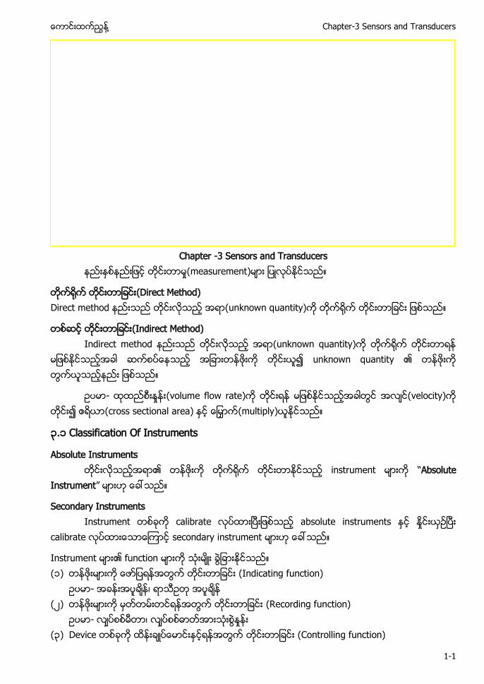
Chapter -3 Sensors and Transducers
(measurement)
(Direct Method) Direct method (unknown quantity)
(Indirect Method) Indirect method (unknown quantity)
unknown quantity ၏
- (volume flow rate) (velocity) (cross sectional area) (multiply)
၃.၁ Classification Of Instruments
Absolute Instruments ၏ instrument “Absolute
Instrument”
Secondary Instruments Instrument calibrate absolute instruments
calibrate secondary instrument
Instrument ၏ function (၁) (Indicating function)
- (၂) (Recording function)
- (၃) Device (Controlling function)

HVAC Control and Building Automation Systems ႔
1-2
- Chilled water flow valve control supply temperature
Measurement system (application) (၁) Monitoring of process and operation. (၂) Control of processes and operation. (၃) Experimental engineering analysis.
Sensor control system sensor sensor (sophisticated) ဤ (chapter) building control system sensor
Sensor controlled variable ၏ control Operator sensor (monitoring) plant ၏
၃-၁ Anatomy of a sensor system
HVAC (application) sensor temperature Carbon Dioxide (CO2) Carbon Monoxide (CO) Relative Humidity dewpoint differential pressure velocity sensor flow sensor ႔ Sensing technology sensor
(measured variable) control module ႔ input process sensor
Sensor (function) (၁) Sensing element: (measured variable)
sensing element

႔ Chapter-3 Sensors and Transducers
1-3
(၂) Transducer: Sensing element electrical signal ႔ active device transducer
(၃) Transmitter: electrical signal control module ႔ ႔ device transmitter
႔ transducer transmitter ႔ ႔ Transducer transmitter ႔၏ “Signal Conditioning”
Signal conditioning ၏ (၁) ၤFiltering to remove noise (၂) Averaging over time (၃) Linearization ႔
system sensing element controller thermocouple controller signal conditioning controller module
Transmitter Transmitter signal signal
(data) device ႔ (device) Transmitter
Transmitter signal 0–5 volt 0–10 volt or 4–20 milliamp (mA) ႔ HVAC voltage output ႔ 4–20 mA signal (robust)
Sensor transmitter ႔ accuracy Sensor sensor ၏ interchangeability
interoperability ႔ control system
Interchangeability sensor sensor (physical replacement)
Interoperability sensor control system (operability)
Sensor installation time accuracy precision reliability repeatability durability maintenance repair/replacement costs compatibility ႔
Status sensor binary output(on/off) Setpoint “ON” output ႔ setpoint “OFF” output

HVAC Control and Building Automation Systems ႔
1-4
Sensor mechanical device Thermostats humidistats pressure switches ႔
t tu ႔ software interlock sensor ၏ output controller digital input (safety-critical) interlock (hardwired) Software interlock
Sensor ၏ status voltage-free contact Analogue sensor measured variable ၏ electrical signal ႔ controller ႔ ႔ input signal control
၃-၂( ) Passive Sensor ၃-၂( ) Active Sensor
Analogue sensor ( ) Passive devices: Transducer sensing element device passive device
Signal conditioning controller resistance type temperature sensor controller ၏ analogue input passive sensor
( ) Active devices: Sensing element signal conditioning transducer transmitter ႔ active device Controller ၏ analogue input passive sensor Transmitter industry standard electrical signal Table 3.1
Table 3.1 Standard signals for transmission of sensor readings Signal Application
0–10 V DC Standard for HVAC applications 4–20 mA Common in process control Voltage-free contact For status indication Pulse Energy and flow measurement
4 to 20 mA signal (two-wire connection) Hostile environments process control 4 to 20 mA signal 0–10 V signal ႔ HVAC systems
Intelligent sensor (measured value) ႔ (status) digital signal ႔ intelligent device ႔ control ႔
NTC "K2" or "K10"
1
2T
E
1
3
4
+ 15 V supply
temperature 0...10 V
Com
႔ Chapter-3 Sensors and Transducers
1-5
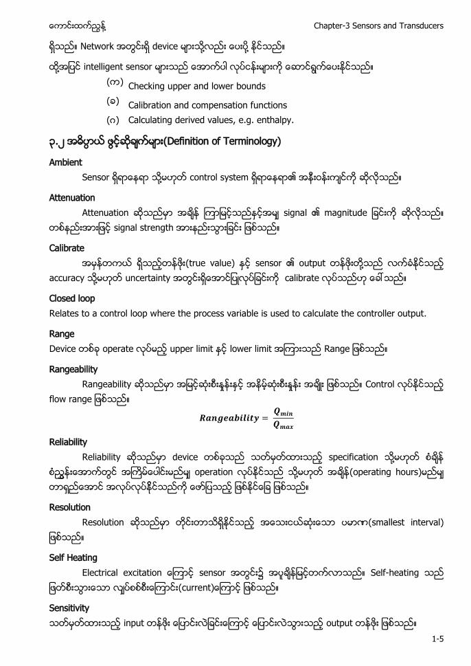
Network device ႔ ႔
႔ intelligent sensor ( ) Checking upper and lower bounds ( ) Calibration and compensation functions (ဂ) Calculating derived values, e.g. enthalpy.
၃.၂ (Definition of Terminology)
Ambient Sensor ႔ control system ၏
Attenuation Attenuation signal ၏ magnitude
signal strength
Calibrate (true value) sensor ၏ output ႔ accuracy ႔ uncertainty calibrate
Closed loop Relates to a control loop where the process variable is used to calculate the controller output.
Range Device operate upper limit lower limit
Rangeability Rangeability Control
o
Reliability Reliability device specification ႔
operation ႔ (operating hours)
Resolution Resolution t t
Self Heating t t t o sensor Self-heating
u t
Sensitivity input output
HVAC Control and Building Automation Systems ႔
1-6
Stiction Static friction
(resistance to motion
Transducer Temperature or pressure physical quantity ၏ volts or millivolts or
resistance change element ႔ device transducer Accuracy
Accuracy (measurement) accuracy o t u t (measurement) (amount of error) accuracy (amount of error) accuracy (true value) (measurement)
Accuracy sensor ၏ ၏ (suitability measuring equipment) Accuracy ႔ total error in the measurement linearity hysteresis repeatability ႔
Reference accuracy (reference conditions) u (ambient temperature) (static pressure) (supply voltage) ႔ o t o
Accuracy error ႔ u t t Systematic bias error random errors (imprecision) (true value) u
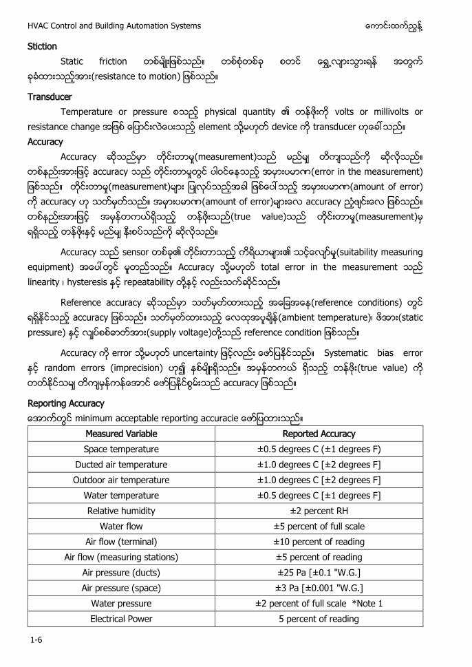
Reporting Accuracy minimum pt po t u
Measured Variable Reported Accuracy Space temperature ±0.5 degrees C (±1 degrees F)
Ducted air temperature ±1.0 degrees C [±2 degrees F] Outdoor air temperature ±1.0 degrees C [±2 degrees F]
Water temperature ±0.5 degrees C [±1 degrees F] Relative humidity ±2 percent RH
Water flow ±5 percent of full scale Air flow (terminal) ±10 percent of reading
Air flow (measuring stations) ±5 percent of reading Air pressure (ducts) ±25 Pa [±0.1 "W.G.] Air pressure (space) ±3 Pa [±0.001 "W.G.]
Water pressure ±2 percent of full scale *Note 1 Electrical Power 5 percent of reading
႔ Chapter-3 Sensors and Transducers
1-7
CO Carbon Monoxide ±10 percent of reading 0-300 ppm CO2 Carbon Dioxide ±50 ppm or 3% of reading
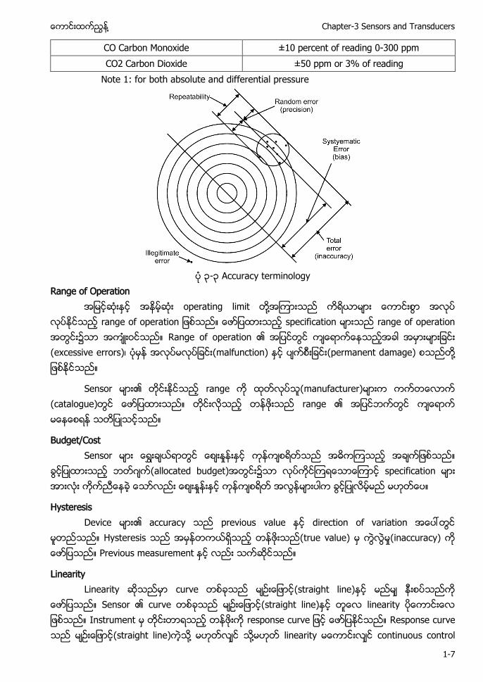
Note 1: for both absolute and differential pressure
၃-၃ Accuracy terminology
Range of Operation operating limit ႔
o op t o specification range of operation Range of operation ၏ (excessive errors) (malfunction) (permanent damage) ႔
Sensor ၏ range (manufacturer) (catalogue) range ၏
Budget/Cost Sensor
ဂ (allocated budget) specification
Hysteresis Device ၏ accuracy previous value direction of variation
Hysteresis (true value) (inaccuracy) Previous measurement
Linearity Linearity curve (straight line)
Sensor ၏ curve (straight line) linearity Instrument po u Response curve (straight line) ႔ ႔ linearity continuous control
HVAC Control and Building Automation Systems ႔
1-8
application ႔ signal (straight line) ႔ linearise
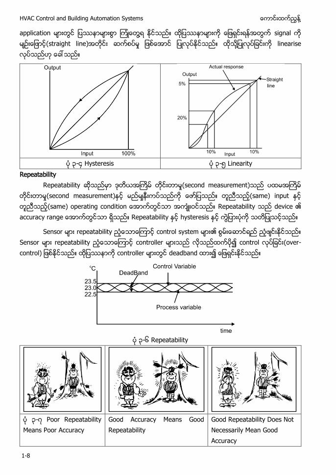
၃-၄ Hysteresis ၃-၅ Linearity
Repeatability Repeatability (second measurement)
(second measurement) (same) input (same) operating condit o Repeatability device ၏ u Repeatability hysteresis
Sensor repeatability control system ၏ Sensor repeatability controller control o - o t o controller deadband
၃-၆ Repeatability
၃-၇ Poor Repeatability Means Poor Accuracy
Good Accuracy Means Good Repeatability
Good Repeatability Does Not Necessarily Mean Good Accuracy
႔ Chapter-3 Sensors and Transducers
1-9
၃-၈ Accuracy and Precision (Hegberg, 2001–2002)
(၃-၂) precise and inaccurate imprecise and relatively accurate ႔ Reliability
Realibility device (mathematical
p o t
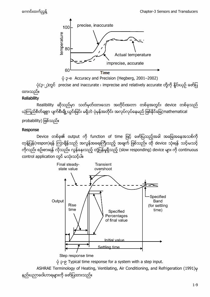
Response Device ၏ output u t o o t
႔ (respon) device ႔ (slow responding) device continuous control application
၃-၉ Typical time response for a system with a step input.
ASHRAE Terminology of Heating, Ventilating, Air Conditioning, and Refrigeration (1991)

HVAC Control and Building Automation Systems ႔
1-10
(measurement) ၏ accuracy ( ) Accuracy of the sensing element: the claimed accuracy of the element may not be
available over the whole operating range or may be quoted under ideal conditions. ( ) Sensitivity: this is the smallest change in themeasured variable that can be detected
by the system. (ဂ) Interacting variables: the condition of the sensormay be affected by other
environmental variables,e.g. an air temperature sensor will be affected by thermal radiation or an RH sensor by local variations in air temperature.
(ဃ) Stability: sensors may drift with time and require checking. Stability is likely to be affected by operating conditions.
( ) Hysteresis: the sensor reading may be affected by its past history and speed and direction of change of the measured variable.
( ) Mounting: the mounting and location of the sensor will affect the reading.
( ) Signal conditioning: associated transducers will introduce their own limitations to the accuracy . o t ‘ t ’ t only transmit when the measured variable has p ‘ t to ’. T u to minimise network traffic.
(ဇ) A/D conversion: the discrimination of any analogue to digital conversion will set a limit to the achievable accuracy. Eight-bit conversion divides the range into 256 steps, 12-bit into 4096 steps. In the latter case, a measurement range of –50 to 150 ºC would have a step size of 0.05 K.
၃.၃ Sensor Performance Characteristic Sensor ၏ static characteristic dynamic characteristic
characteristic static characteristic Static Characteristics Dynamic Characteristics
Accuracy Scale range Speed of response Drift Scale span Measuring lag Dead Zone Noise Fidelity Static Error Dead Time Dynamic error Sensitivity Hysteresis. Reproducibility Linearity Static correction
႔ Chapter-3 Sensors and Transducers
1-11
Actuator Expected Performance Characteristic
Sensor Type Expected Response Time Performance Assurance Air Flow Damper 30 second Sensor Feedback Evacuation 60 second Supervised Admittance 1 second Supervised Lighting 100 millisecond Optical Sensing Smoke Control Damper 10 second Supervised Smoke Abatement 60 second Supervised
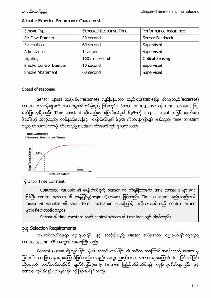
Speed of response
Sensor ၏ ႔ (response) (stable) (accurate) control Speed of response t o t t Time constant ၏ ၆၃% output singal ၏ ၆၃% time constant medium ႔
၃-၁၀ Time Constant
၃.၄ Selection Requirements sensor ႔
control system
Control system ၏ sensor sensor t ႔ (early failure) control ႔
Controlled variable ၏ sensor time constant control system ၏ ႔ po Time constant measured variable ၏ short term fluctuation control action
Sensor ၏ time constant control system ၏ time lags

HVAC Control and Building Automation Systems ႔
1-12
sensor (inaccuracy) (failure) ႔ sensor o t t t o
Table 3.2 Sensor requirements Sensor requirement Checklist Type Status, analogue, intelligent Sensed medium Air, water, gas, oil Sensed quantity Temperature, pressure, velocity, humidity Location Space, duct, pipe Housing Accessibility, effect on accuracy and speed Accuracy Accuracy, resolution, hysteresis, repeatability Operating range The range over which the sensor performs accurately Overload range The range to which the sensor may be subjected without damage Response time Affected by sensor, housing and medium Protection Is protection required from a damaging environment? Maintenance Calibration requirements, ease of servicing and replacement Interchangeability Can sensor be replaced by another from the same or different
manufacturer? Cost Initial cost and total ownership cost over life cycle
Sensor selection criteria: Sensor Range: Sensor ၏ accuracy range
Sensitivity: u o t t
Linearity: Linearity between the change in input variable and the change in output variable. Signal conditioning is required for nonlinear sensors
Response time: The time taken for the sensor output to change for a given change in the sensor input
Accuracy: Sensor (sensor output value) (true value) ႔၏ (error) u
Repeatability: Sensor ၏ consistency
Interchangeability: R - t sensor
Ease of calibration: The ease of establishing and maintaining the calibration of a sensor
Stability: Sensor ၏
႔ Chapter-3 Sensors and Transducers
1-13
Cost: Consideration of the appropriate cost for the value of information gained from the sensor
(manufacturer) pressure transducer ၏ specifications Operation Input range 0–1000 cm H2O Excitation 15 V DC Output range 0–5 V Performance Linearity error 0.5% full-scale operating range Hysteresis error Less than 0.15% full-scale operating range Sensitivity error 0.25% of reading Thermal sensitivity error 0.02%/°C of reading Thermal zero drift 0.02%/°C full-scale operating range Temperature range 0–50 °C
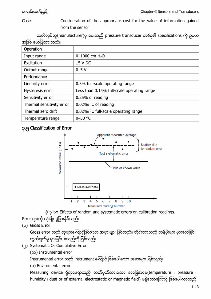
၃.၅ Classification of Error
၃-၁၁ Effects of random and systematic errors on calibration readings.
Error (၁) Gross Error
Gross error ႔
(၂) Systematic Or Cumulative Error ( ) Instrumental error Instrumental error instrument ( ) Enviromental error Measuring device (temperature pressure humidity dust or of external electrostatic or magnetic field)

HVAC Control and Building Automation Systems ႔
1-14
(ဂ) Observational Error
(၃) Random Or Residual Or Accidental Error Residual error
(measurement) ၏ accuracy instrument error (၅)
၃-၁၂ ( ) Hysteresis error ၃-၁၂ ( ) Linearity error
၃-၁၂ (ဂ) Sensitivity error ၃-၁၂ (ဃ) Zero shift (null) error
၃-၁၂ ( ) Repeatability error
၃.၆ Temperature Sensors Air-conditioning application (temperature) primary
o t o Comfort HVAC application (temperature) u o o t ၏ Humidity air velocity radiant temperature ႔ u o o t t p tu Temperature sensor
႔ Chapter-3 Sensors and Transducers
1-15
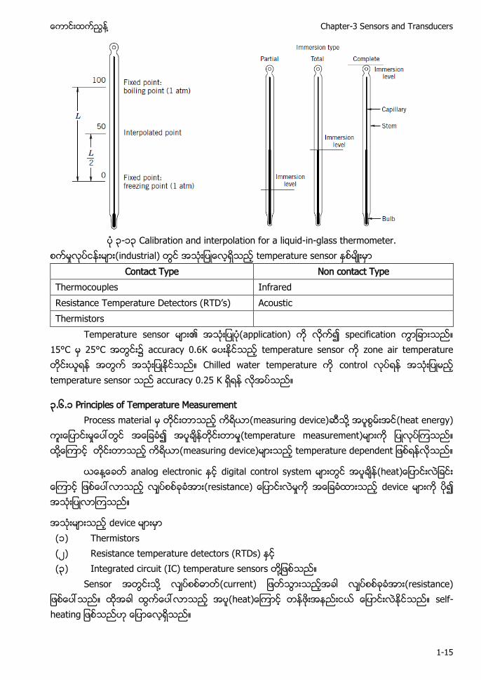
၃-၁၃ Calibration and interpolation for a liquid-in-glass thermometer.
(industrial) temperature sensor Contact Type Non contact Type
Thermocouples Infrared t T p tu D t to TD’ Acoustic Thermistors
Temperature sensor ၏ (application) specification 15°C 25°C accuracy 0.6 temperature sensor zone air temperature Chilled water temperature control temperature sensor accuracy 0.25 K
၃.၆.၁ Principles of Temperature Measurement Process material (measuring device) ႔ (heat energy)
(temperature measurement) ႔ (measuring device) t p tu p t
႔ analog electronic digital control system t t device
device (၁) Thermistors (၂) Resistance temperature detectors (RTDs) (၃) Integrated circuit (IC) temperature sensors ႔
Sensor ႔ u t t t - t
HVAC Control and Building Automation Systems ႔
1-16
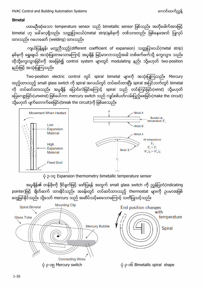
Bimetal temperature sensor bimetalli o
bimetal (metal strip) ဂ (welding)
႔ (different coefficient of expansion) (metal strip) ႔ ႔ control system modulating ႔ two-position
Two-position electric control spiral bimetal Mercury small glass switch spiral spiral bimetal spiral (wind) ႔ u mercury switch (make the circuit) ႔ (break the circuit)
၃-၁၄ Expansion thermometry bimetallic temperature sensor
၏ small glass switch t po t thermostat ႔ ႔ mercury
၃-၁၅ Mercury switch ၃-၁၆ Bimetallic spiral shape
႔ Chapter-3 Sensors and Transducers
1-17
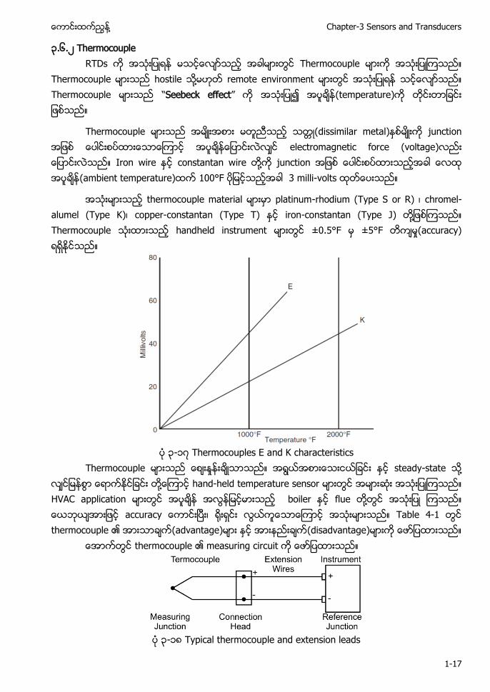
၃.၆.၂ Thermocouple RTDs Thermocouple
Thermocouple hostile ႔ remote environment Thermocouple “Seebeck effect” (temperature)
Thermocouple (dissimilar metal) junction electromagnetic force (voltage) Iron wire constantan wire ႔ junction (ambient temperature) 100°F 3 milli-volts
thermocouple material platinum-rhodium (Type S or R) chromel-alumel (Type K) copper-constantan (Type T) iron-constantan (Type J) ႔ Thermocouple handheld instrument ±0.5°F ±5°F (accuracy)
၃-၁၇ Thermocouples E and K characteristics
Thermocouple steady-state ႔ ႔ hand-held temperature sensor HVAC application boiler flue ႔ u Table 4-1 thermocouple ၏ (advantage) (disadvantage)
thermocouple ၏ measuring circuit
၃-၁၈ Typical thermocouple and extension leads
HVAC Control and Building Automation Systems ႔
1-18
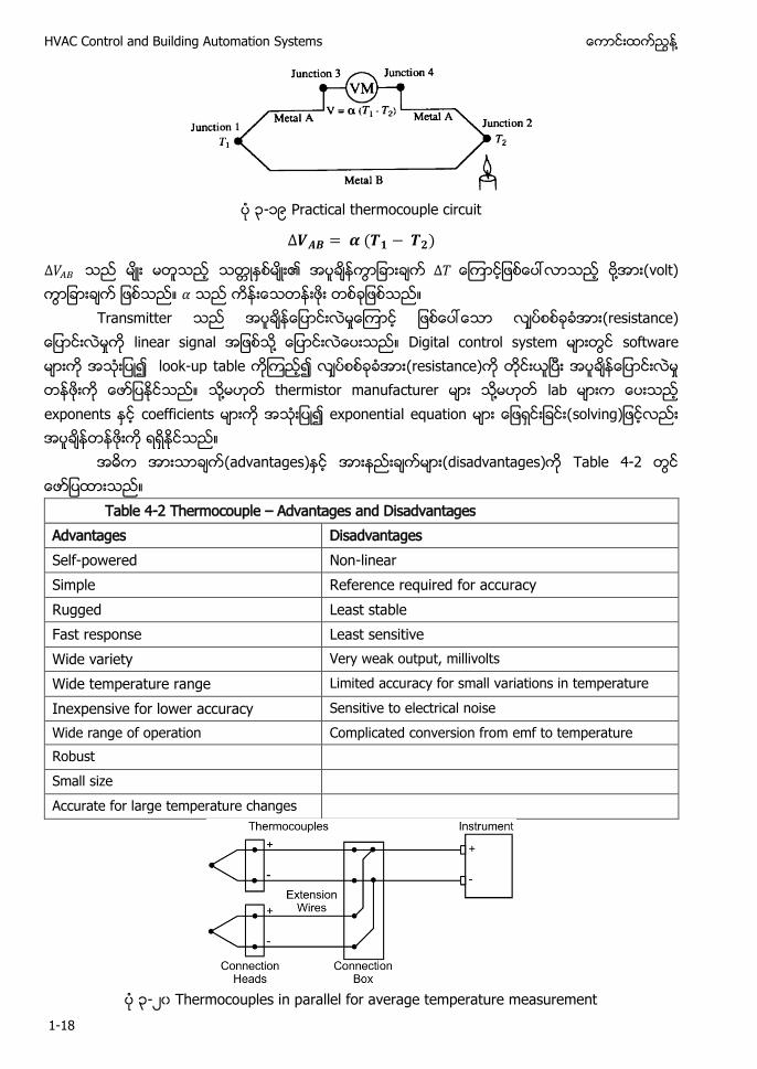
၃-၁၉ Practical thermocouple circuit
၏ ႔ (volt)
Transmitter t linear signal ႔ Digital control system software look-up table (resistance) ႔ thermistor manufacturer ႔ lab exponents coefficients exponential equation o
(advantages) (disadvantages) Table 4-2
Table 4-2 Thermocouple – Advantages and Disadvantages Advantages Disadvantages Self-powered Non-linear Simple Reference required for accuracy Rugged Least stable Fast response Least sensitive Wide variety Very weak output, millivolts Wide temperature range Limited accuracy for small variations in temperature Inexpensive for lower accuracy Sensitive to electrical noise Wide range of operation Complicated conversion from emf to temperature Robust Small size Accurate for large temperature changes
၃-၂၀ Thermocouples in parallel for average temperature measurement
႔ Chapter-3 Sensors and Transducers
1-19
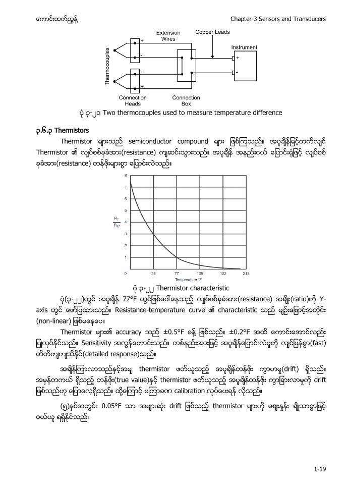
၃-၂၁ Two thermocouples used to measure temperature difference
၃.၆.၃ Thermistors Thermistor semiconductor compound
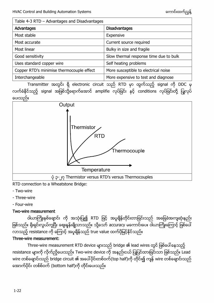
Thermistor ၏ (resistance) (resistance)
၃-၂၂ Thermistor characteristic
(၃-၂၂) 77°F (resistance) (ratio) Y-axis Resistance-temperature curve ၏ characteristic o -
Thermistor ၏ accuracy ±0.5°F ႔ ±0.2°F Sensitivity (fast) (detailed response)
thermistor (drift) (true value) thermistor t ႔ calibration
(၅) 0.05°F t thermistor
HVAC Control and Building Automation Systems ႔
1-20
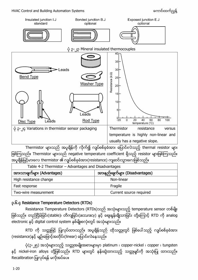
၃-၂၃ Mineral insulated thermocouples
၃-၂၄ Variations in thermistor sensor packaging Thermistor resistance versus
temperature is highly non-linear and usually has a negative slope.
Thermistor thermal resistor Thermistor negative temperature coefficient resistor thermistor ၏ (resistance)
Table 4-2 Thermistor – Advantages and Disadvantages (Advantages) (Disadvantages) High resistance change Non-linear Fast response Fragile Two-wire measurement Current source required
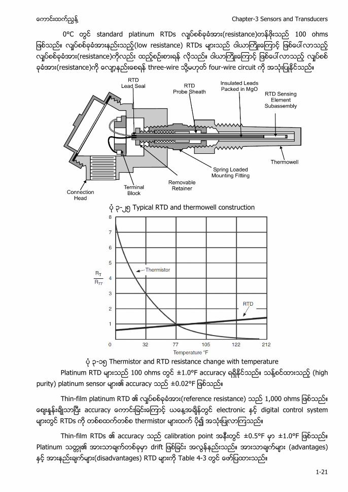
၃.၆.၄ Resistance Temperature Detectors (RTDs) Resistance Temperature Detectors (RTDs) temperature sensor
(stable) (accuracy) ႔ RTD analog electronic digital control system
RTD (resistance)
(၃-၂၅) platinum copper-nickel copper tungsten nickel-iron alloys ႔ RTD t o
႔ Chapter-3 Sensors and Transducers
1-21
0°C standard platinum RTDs (resistance) o (low resistance) RTDs (resistance) (resistance) three-wire ႔ four-wire circuit
၃-၂၅ Typical RTD and thermowell construction
၃-၁၅ Thermistor and RTD resistance change with temperature
Platinum RTD 100 ohms ±1.0°F accuracy ႔ (high purity) platinum sensor ၏ accuracy . F
Thin-film platinum RTD ၏ (reference resistance) o u ႔ electronic digital control system RTDs thermistor
Thin-film RTDs ၏ accuracy calibration point ±0.5°F . F Platinum ၏ t (advantages) (disadvantages) RTD Table 4-3
HVAC Control and Building Automation Systems ႔
1-22
Table 4-3 RTD – Advantages and Disadvantages Advantages Disadvantages Most stable Expensive Most accurate Current source required Most linear Bulky in size and fragile Good sensitivity Slow thermal response time due to bulk Uses standard copper wire Self heating problems Copp TD’ t o oup t More susceptible to electrical noise Interchangeable More expensive to test and diagnose
Transmitter electronic circuit RTD signal DDC signal ႔ amplifie conditions ႔
၃-၂၇ T to u TD’ u T o oup
RTD connection to a Wheatstone Bridge: - Two-wire - Three-wire - Four-wire Two-wire measurement
RTD ႔ accuracy resistance true value Three-wire measurement:
Three-wire measurement RTD device bridge ၏ lead wires resistance Two-wire device Lead wire bridge circuit ၏ (top half) wire (bottom half)
႔ Chapter-3 Sensors and Transducers
1-23
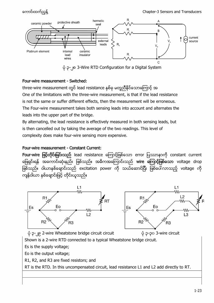
၃-၂၈ 3-Wire RTD Configuration for a Digital System
Four-wire measurement - Switched: three-wire measurement lead resistance One of the limitations with the three-wire measurement, is that if the lead resistance is not the same or suffer different effects, then the measurement will be erroneous. The Four-wire measurement takes both sensing leads into account and alternates the leads into the upper part of the bridge. By alternating, the lead resistance is effectively measured in both sensing leads, but is then cancelled out by taking the average of the two readings. This level of complexity does make four-wire sensing more expensive.
Four-wire measurement - Constant Current: Fou - lead resistance o constant current wire voltage drop excitation power voltage
၃-၂၉ 2-wire Wheatstone bridge circuit circuit ၃-၃၀ 3-wire circuit
Shown is a 2-wire RTD connected to a typical Wheatstone bridge circuit. Es is the supply voltage; Eo is the output voltage; R1, R2, and R3 are fixed resistors; and RT is the RTD. In this uncompensated circuit, lead resistance L1 and L2 add directly to RT.
HVAC Control and Building Automation Systems ႔
1-24
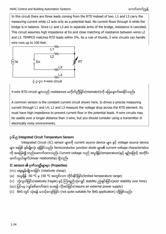
In this circuit there are three leads coming from the RTD instead of two. L1 and L3 carry the measuring current while L2 acts only as a potential lead. No current flows through it while the bridge is in balance. Since L1 and L3 are in separate arms of the bridge, resistance is canceled. This circuit assumes high impedance at Eo and close matching of resistance between wires L2 and L3. TEMPCO matches RTD leads within 5%. As a rule of thumb, 3 wire circuits can handle wire runs up to 100 feet.
၃-၃၁ 4-wire circuit 4-wire RTD circuit resistances (mismatch) A common version is the constant current circuit shown here. Is drives a precise measuring current through L1 and L4; L2 and L3 measure the voltage drop across the RTD element. Eo must have high impedance to prevent current flow in the potential leads. 4-wire circuits may be usable over a longer distance than 3-wire, but you should consider using a transmitter in electrically noisy environments.
၃.၆.၅ Integrated Circuit Temperature Sensors Integrated Circuit (IC) sensor current source device voltage source device
Semiconductor junction diode ၏ current-voltage characteristics Current-voltage (temperature) (linear relationship)
IC sensors ၏ ဂ (Properties) ( ) (relatively cheap) ( ) -50 °C 150 °C (limited temperature range) (ဂ) (relatively fragile) stability (poor stability over time) (ဃ) (require an external power supply) ( ) BAS (not quite suitable for BAS application) ႔
႔ Chapter-3 Sensors and Transducers
1-25
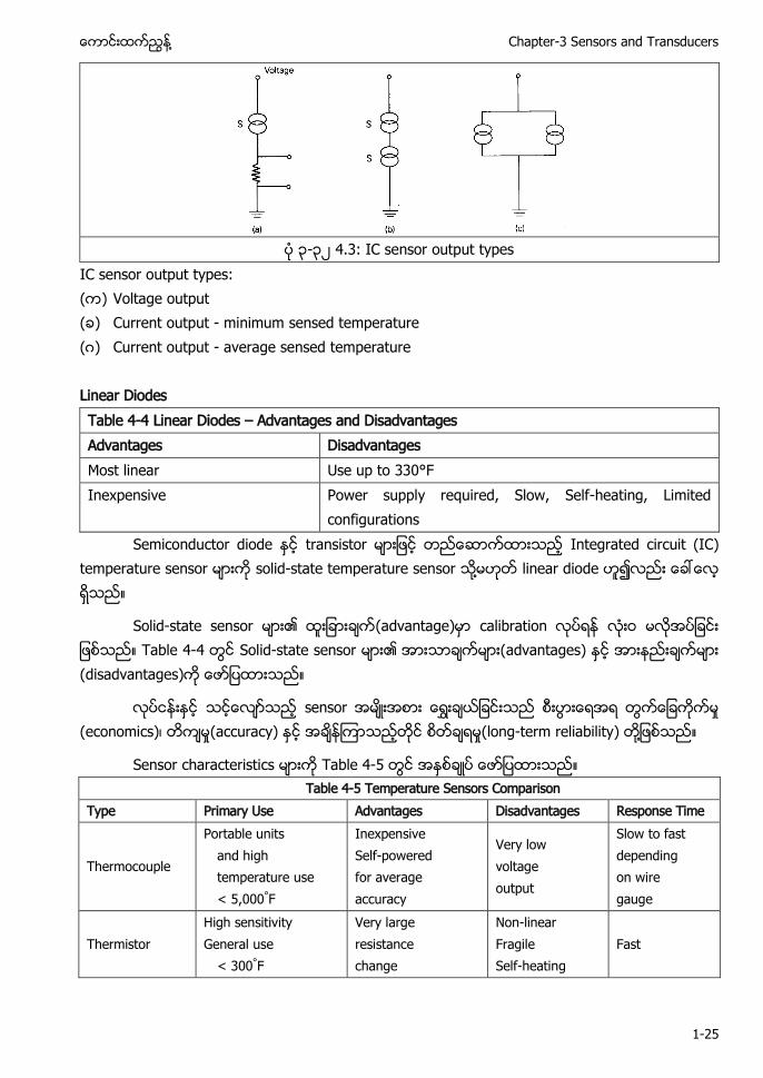
၃-၃၂ 4.3: IC sensor output types
IC sensor output types: ( ) Voltage output ( ) Current output - minimum sensed temperature (ဂ) Current output - average sensed temperature Linear Diodes Table 4-4 Linear Diodes – Advantages and Disadvantages Advantages Disadvantages Most linear Use up to 330°F Inexpensive Power supply required, Slow, Self-heating, Limited
configurations Semiconductor diode transistor Integrated circuit (IC)
temperature sensor solid-state temperature sensor ႔ linear diode
Solid-state sensor ၏ (advantage) calibration Table 4-4 Solid-state sensor ၏ (advantages) (disadvantages)
sensor (economics) (accuracy) (long-term reliability) ႔
Sensor characteristics Table 4-5 Table 4-5 Temperature Sensors Comparison
Type Primary Use Advantages Disadvantages Response Time
Thermocouple
Portable units and high temperature use < 5,000°F
Inexpensive Self-powered for average accuracy
Very low voltage output
Slow to fast depending on wire gauge
Thermistor High sensitivity General use
< 300°F
Very large resistance change
Non-linear Fragile Self-heating
Fast
HVAC Control and Building Automation Systems ႔
1-26
RTD General purpose
< 1,400°F
Very accurate Interchangeable Very stable
Relatively expensive
Long for coil Medium/ fast
for foil Short for thin film
Integrated circuit General purpose <400°F
Linear output Relatively inexpensive
Not rugged limited selection
Medium / Fast
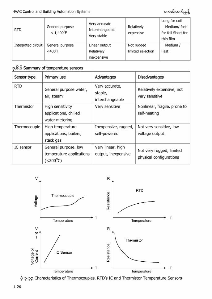
၃.၆.၆ Summary of temperature sensors
Sensor type Primary use Advantages Disadvantages
RTD General purpose water, air, steam
Very accurate, stable, interchangeable
Relatively expensive, not very sensitive
Thermistor High sensitivity applications, chilled water metering
Very sensitive Nonlinear, fragile, prone to self-heating
Thermocouple High temperature applications, boilers, stack gas
Inexpensive, rugged, self-powered
Not very sensitive, low voltage output
IC sensor General purpose, low temperature applications (<200OC)
Very linear, high output, inexpensive
Not very rugged, limited physical configurations
၃-၃၃ C t t o T o oup TD’ IC T to T p tu Sensors
႔ Chapter-3 Sensors and Transducers
1-27
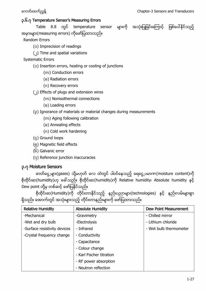
၃.၆.၇ Temperature Sensor’ Measuring Errors T . temperature sensor
measuring errors Random Errors ၁ Imprecision of readings ၂ Time and spatial variations Systematic Errors ၁ Insertion errors, heating or cooling of junctions Conduction errors Radiation errors ဂ Recovery errors ၂ Effects of plugs and extension wires Nonisothermal connections Loading errors ၃ Ignorance of materials or material changes during measurements Aging following calibration Annealing effects ဂ Cold work hardening ၄ Ground loops ၅ Magnetic field effects ၆ Galvanic error ၇ Reference junction inaccuracies
၃.၇ Moisture Sensors (gases) ႔ (moisture content)
(humidity) (humidity) Relative humidity Absolute humidity Dew point ႔
(Humidity) (technologies)
Relative Humidity Absolute Humidity Dew Point Measurement -Mechanical -Wet and dry bulb -Surface resistivity devices -Crystal frequency change
-Gravimetry -Electrolysis - Infrared - Conductivity - Capacitance - Colour change - Karl Fischer titration - RF power absorption - Neutron reflection
- Chilled mirror - Lithium chloride - Wet bulb thermometer
HVAC Control and Building Automation Systems ႔
1-28
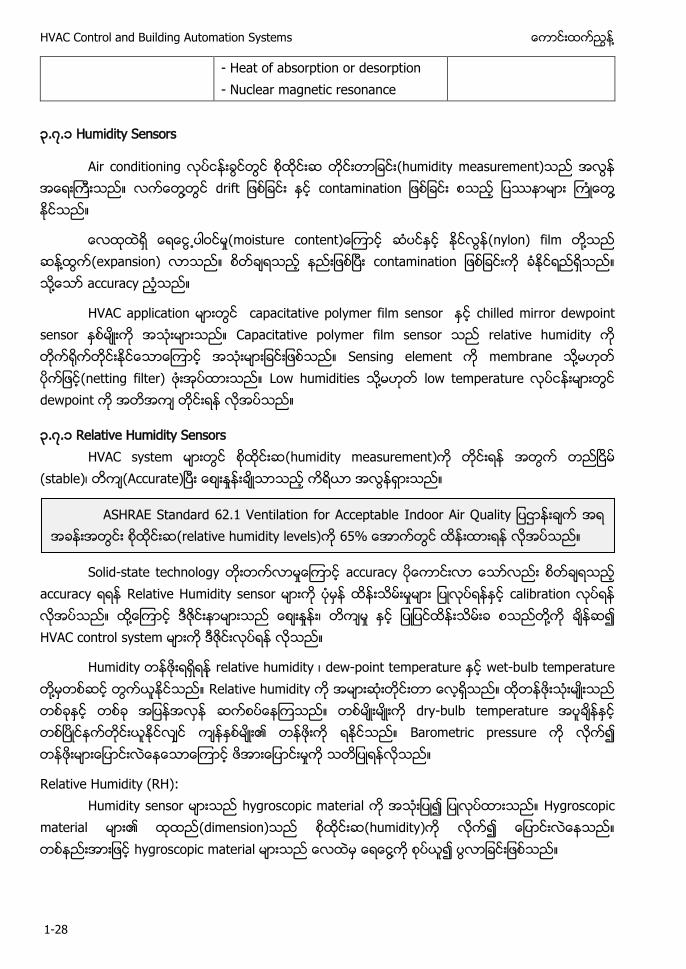
- Heat of absorption or desorption - Nuclear magnetic resonance
၃.၇.၁ Humidity Sensors
Air conditioning (humidity measurement) ႔ t o t t o ႔
o tu o t t (nylon) film ႔ ႔ (expansion) o t t o ႔ accuracy
HVAC application capacitative polymer film sensor chilled mirror dewpoint sensor Capacitative polymer film sensor relative humidity Sensing element membrane ႔ (netting filter) Low humidities ႔ low temperature dewpoint
၃.၇.၁ Relative Humidity Sensors HVAC system (humidity measurement)
(stable) (Accurate)
Solid-state technology accuracy
accuracy Relative Humidity sensor calibration ႔ ဇ ႔ HVAC control system ဇ
Humidity relative humidity dew-point temperature wet-bulb temperature ႔ Relative humidity dry-bulb temperature ၏ Barometric pressure
Relative Humidity (RH): Humidity sensor hygroscopic material Hygroscopic
material ၏ (dimension) (humidity) hygroscopic material ႔
ASHRAE Standard 62.1 Ventilation for Acceptable I oo u t (relative humidity levels)
႔ Chapter-3 Sensors and Transducers
1-29
(animal hair) (wood) (various fabrics) ႔ hygroscopic material portable sensor Accuracy ±5% relative humidity
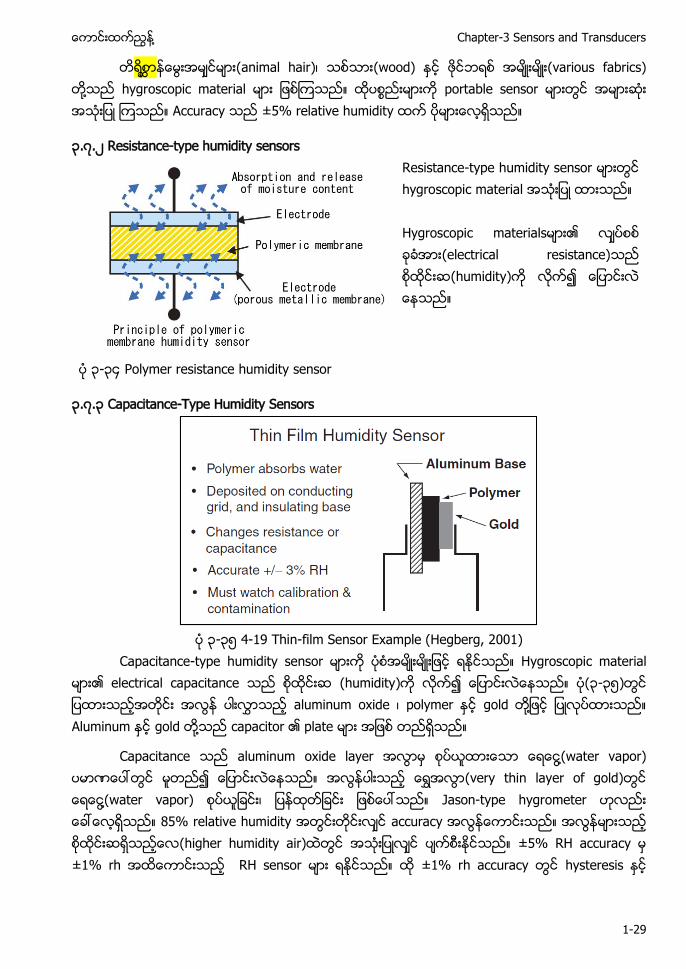
၃.၇.၂ Resistance-type humidity sensors
Resistance-type humidity sensor hygroscopic material Hygroscopic materials ၏ (electrical resistance) (humidity)
၃-၃၄ Polymer resistance humidity sensor
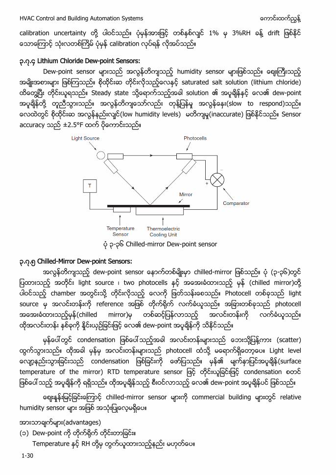
၃.၇.၃ Capacitance-Type Humidity Sensors
၃-၃၅ 4-19 Thin-film Sensor Example (Hegberg, 2001)
Capacitance-type humidity sensor Hygroscopic material ၏ electrical capacitance (humidity) (၃-၃၅) aluminum oxide polymer gold ႔ Aluminum gold ႔ capacitor ၏ plate
Capacitance aluminum oxide layer ႔(water vapor) (very thin layer of gold) ႔(water vapor) Jason-type hygrometer 85% relative humidity accuracy (higher humidity air) ±5% RH accuracy ±1% rh RH sensor ±1% rh accuracy hysteresis
HVAC Control and Building Automation Systems ႔
1-30
calibration uncertainty ႔ 1% 3%RH ႔ t calibration
၃.၇.၄ Lithium Chloride Dew-point Sensors: Dew-point sensor humidity sensor
saturated salt solution (lithium chloride) ႔ Steady state ႔ solution ၏ ၏ dew-point ႔ ႔ (slow to respond) (low humidity levels) u t Sensor accuracy ±2.5°F
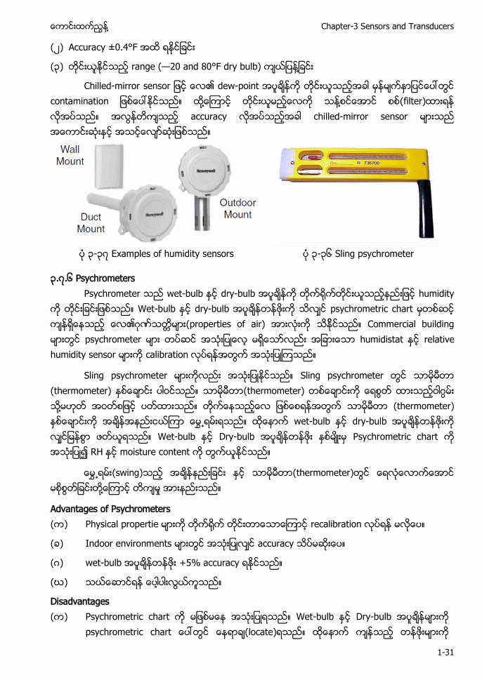
၃-၃၆ Chilled-mirror Dew-point sensor
၃.၇.၅ Chilled-Mirror Dew-point Sensors: -po t o - o (၃-၃၆)
light source two photocells (chilled mirror) ႔ chamber ႔ Photocell light source reference photocell (chilled mirror) ၏ dew-point
o t o ႔ ႔ (scatter) photocell ႔ L t o t o ၏ u t p tu o t o TD t p tu o condensation ၏ dew-point
chilled-mirror sensor commercial building relative humidity sensor
(advantages) (၁) Dew-point
Temperature RH ႔
႔ Chapter-3 Sensors and Transducers
1-31
(၂) Accuracy ±0.4°F
(၃) range (—20 and 80°F dry bulb) ႔
Chilled-mirror sensor ၏ dew-point co t t o ႔ ႔ (filter) accuracy chilled-mirror sensor
၃-၃၇ Examples of humidity sensors ၃-၃၆ Sling psychrometer
၃.၇.၆ Psychrometers Psychrometer wet-bulb dry-bulb humidity
Wet-bulb dry-bulb psychrometric chart ၏ဂ (properties of air) Commercial building psychrometer humidistat relative humidity sensor calibration
Sling psychrometer Sling psychrometer (thermometer) (thermometer) ဂ ႔ (thermometer) wet-bulb dry-bulb Wet-bulb Dry-bulb Psychrometric chart RH moisture content
(swing) (thermometer) ႔
Advantages of Psychrometers ( ) Physical propertie recalibration
( ) Indoor environments accuracy
(ဂ) wet-bulb +5% accuracy
(ဃ)
Disadvantages ( ) Psychrometric chart Wet-bulb Dry-bulb
psychrometric chart (locate)
HVAC Control and Building Automation Systems ႔
1-32
( ) Duct
(ဂ) (low-relative-humidity) (ဃ) (thermometer) error
( ) Contamination error
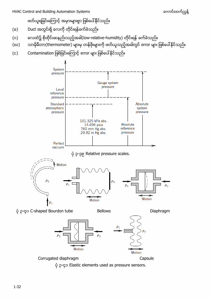
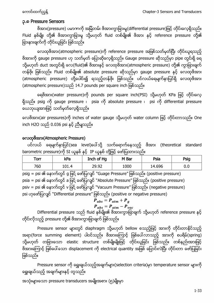
၃-၃၉ Relative pressure scales.
၃-၄၀ C-shaped Bourdon tube Bellows Diaphragm
Corrugated diaphragm Capsule
၃-၄၁ Elastic elements used as pressure sensors.
႔ Chapter-3 Sensors and Transducers
1-33
၃.၈ Pressure Sensors (pressure) t p u
Fluid ႔၏ ႔ fluid ၏ reference pressure ႔၏
(atmospheric pressure) reference pressure gauge pressure Gauge pressure pipe ႔ duct (fluid)၏ (atmospheric pressure) ႔၏ Fluid ၏ absolute pressure gauge pressure (atmospheric pressure) ႔ (atmospheric pressure) . pou p u
(water pressure) pounds per square inch(PSI) ႔ psig gauge pressure psia absolute pressure psi t p u
(air pressures) inches of water gauge ႔ t o u One inch H2O 0.036 psi (Atmospheric Pressure) (sea level ႔ (theoretical standard barometric pressure) SI IP ႔
Torr kPa Inch of Hg M Bar Psia Psig 760 101.4 29.92 1000 14.696 0.0
psig = psi ၏ ႔ “Gu ressure” (positive pressure) psia = psi ၏ ႔ “ bsolute Pressure” (positive pressure) psiv = psi ၏ v ႔ “Vacuum Pressure” (negative pressure) psi “Differential pressure” (positive or negative pressure)
Differential pressure fluid ၏ ႔ reference pressure pressure ႔၏
Pressure sensor diaphragm ႔ bellow (force summing element) (spring) ႔ elastic structure displacement electrical quantity
Pressure sensor (selection criteria) temperature sensor
pressure transducers (၅)
HVAC Control and Building Automation Systems ႔
1-34
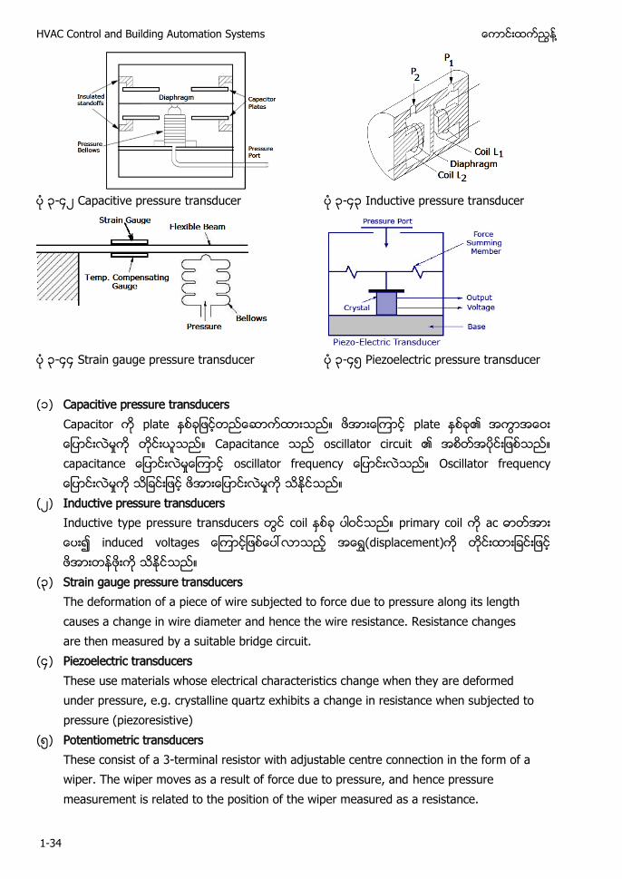
၃-၄၂ Capacitive pressure transducer ၃-၄၃ Inductive pressure transducer
၃-၄၄ Strain gauge pressure transducer ၃-၄၅ Piezoelectric pressure transducer
(၁) Capacitive pressure transducers
Capacitor plate plate ၏ Capacitance oscillator circuit ၏ capacitance oscillator frequency Oscillator frequency
(၂) Inductive pressure transducers Inductive type pressure transducers coil primary coil ac induced voltages (displacement)
(၃) Strain gauge pressure transducers The deformation of a piece of wire subjected to force due to pressure along its length causes a change in wire diameter and hence the wire resistance. Resistance changes are then measured by a suitable bridge circuit.
(၄) Piezoelectric transducers These use materials whose electrical characteristics change when they are deformed under pressure, e.g. crystalline quartz exhibits a change in resistance when subjected to pressure (piezoresistive)
(၅) Potentiometric transducers These consist of a 3-terminal resistor with adjustable centre connection in the form of a wiper. The wiper moves as a result of force due to pressure, and hence pressure measurement is related to the position of the wiper measured as a resistance.

႔ Chapter-3 Sensors and Transducers
1-35
၃.၈.၁ Summary of pressure sensors for BAS applications Sensor type Primary use Advantage Disadvantage Capacitive low-pressure air; duct
static or filter differential pressure
Cheap Complex signal conditioning
Inductive Low pressure Rugged Expensive, temp compensation difficult
Strain gauge High pressure, chilled water, steam
Linear output Low output signal
Piezoelectric Fluctuating pressures, sound, mech. vibration
Wide pressure range
Difficult to calibrate
Potentiometric General purpose Cheap, high output
Low accuracy, large size, physical wear reduces life
၃-၄၆ Potentiometric pressure transducers
၃.၈.၂ Mechanical Pressure Gauges: (၃-၄၆) pressure gauge Bourdon tube sensing element
Bourdon tube p tu atmospheric pressure reference Bourdon tube ႔ (linkage) ဂ (gear) (indicating pointer) Bourdon and spiral tube water system

HVAC Control and Building Automation Systems ႔
1-36
၃-၄၇ 4-22 Bourdon Tube Pressure Sensor
၃-၄၈ 4-22 Bourdon tube pressure gauge.
၃.၈.၃ Diaphragm sensor (၃-၄၉ ) diaphragm sensor chamber flexible wall
႔ p (thin steel sheet) diaphragm Fabric diaphragm ၏ (psi) ႔ pressure gauge ႔ pressure range Pressure range
႔ Chapter-3 Sensors and Transducers
1-37
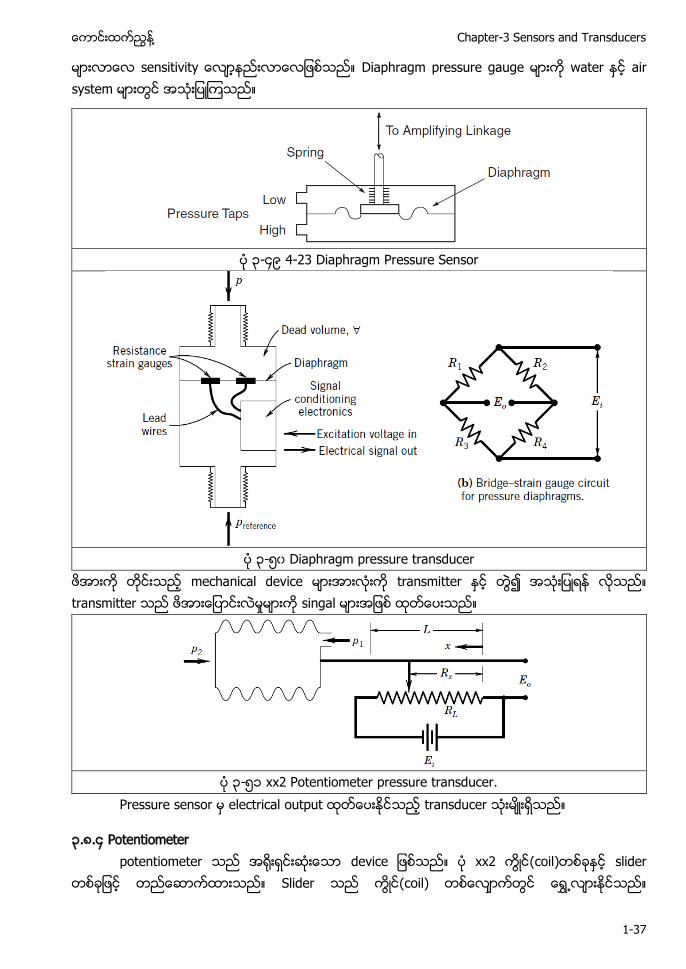
t t Diaphragm pressure gauge water air system
၃-၄၉ 4-23 Diaphragm Pressure Sensor
၃-၅၀ Diaphragm pressure transducer
mechanical device transmitter transmitter singal
၃-၅၁ xx2 Potentiometer pressure transducer.
Pressure sensor electrical output transducer
၃.၈.၄ Potentiometer potentiometer device xx2 (coil) slider
Slider (coil)

HVAC Control and Building Automation Systems ႔
1-38
o transmitter Potentiometric accuracy
၃.၈.၅ Electrical Pressure Guages: Piezoelectric pressure sensor pressure sensor
(measure continuous) Piezoelectric pressure sensor t output signal
update
၃.၈. ၆ Capacitance pressure detector Capacitive pressure measurement p
p t Sensor high frequency oscillator pressure changes diaphragm ၏ bridge circuit p t
၃-၅၂ Capacitive sensor ၃-၅၃ Inductive sensor
Capacitance sensor (၃-၅၂) Capacitor plate plate ၏ Capacitance oscillator circuit ၏ C p t o to u O to u
(၃-၅၃) inductive sensor metal core (coil) transformer Metal core M t o metal core magnetic flux transmitter ႔
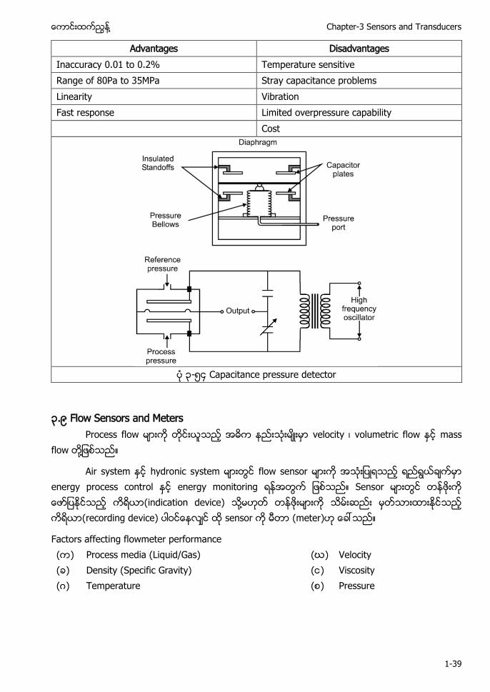
capacitance pressure detector two-plate design p to ဤ (accurate) operating range Capacitive pressure measurement ၏
႔ Chapter-3 Sensors and Transducers
1-39
Advantages Disadvantages Inaccuracy 0.01 to 0.2% Temperature sensitive Range of 80Pa to 35MPa Stray capacitance problems Linearity Vibration Fast response Limited overpressure capability Cost
၃-၅၄ Capacitance pressure detector
၃.၉ Flow Sensors and Meters Process flow velocity volumetric flow mass
flow ႔
Air system hydronic system flow sensor energy process control energy monitoring Sensor (indication device) ႔ (recording device) sensor (meter)
Factors affecting flowmeter performance ( ) Process media (Liquid/Gas) (ဃ) Velocity ( ) Density (Specific Gravity) ( ) Viscosity (ဂ) Temperature ( ) Pressure
HVAC Control and Building Automation Systems ႔
1-40
Volumetric Flowmeter ( ) DP ( ) Target ( ) Turbine ( ) Ultrasonic (ဂ) Vortex / Swirl ( ) Displacement (ဃ) Magnetic
HVAC ACMV flow control chilled water flow condenser water flow hot water flow air flow ႔ HVAC applications flow sensor
(၁) Differential pressure flow sensors (၂) Displacement flow sensors (၃) Passive flow sensors (၄) Mass flow sensors ႔
fluid u op fitting obstruction eddy vortice flow sensor ၏
Flow sensor ႔ duct upstream duct/pipe diameter ၏ (၂) (၁၀) downstream duct/pipe diameter ၏ (၂) (၃)
႔ duct straightening vane ႔ grid accuracy (water) (air) flow meter
Differential Pressure Flowmeters Advantages Disadvanteages Use On Liquid, Gas, and Steam Limited Rangeability Suitable for Extreme Temperatures and Pressures
Effected By Changes In Density, Pressure, and Viscosity
No Moving Parts Maintenance Intensive Low Cost

႔ Chapter-3 Sensors and Transducers
1-41
၃.၉.၁ Differential Pressure Flow Meters
Differential pressure (flow) B ou ’ u t o Differential pressure (flow)
√
Differential Pressure Flow Meters:
where V is the velocity, C is a constant that is a function of the physical design of the meter, DP is the measured pressure drop, and ρ is the fluid density.
HVAC system ႔၏ ႔ (density)
၃.၉.၂ Orifice Meter
၃-၅၅ 4-26 Orifice Plate Flow Meter
4-26 orifice plate meter ၏ Orifice plate (with round sharp edged) plate Orifice plate fluid ၏ Reynolds Number flow rate pressure drop ႔

HVAC Control and Building Automation Systems ႔
1-42
√
Orifice plate flow coefficient C measured area of the pipe and
orifice opening (determine )
device flow coefficient C ႔ (experiment) orifice meter flow meter calibrate Orifice meter (pressure drop) HVAC system Reynolds Number flow (lamina flow) accuracy (wear) ႔ HVAC system
၃.၉.၃ Venturi Meter
၃-၅၆ 4-27 Venturi flow meter (၃-၅၆) Venturi flow meter Venturi meter orifice
meter ႔၏ (inlet) (outlet) Venturi meter ၏ (pressure drop) static pressure velocity (kinetic energy) ႔
(inlet) static pressure velocity Flow coefficient (test)
√

႔ Chapter-3 Sensors and Transducers
1-43
၃-၅၇ The Herschel venturi meter with the associated flow pressure drop along its axis.
Venturi meter steam flow measurement Water flow measurement air flow measurement Standard density
၃-၅၈ 4-28 Averaging Type, Pipe-mounted Pitot Meter

HVAC Control and Building Automation Systems ႔
1-44
√ Equation 4-2
where DP is in psi and V is in feet per second (fps).
(၃-၅၈) pitot flow sensor velocity profile (natural distortion) Velocity pressure port tube Sensor tube tu u u Downstream static pressure
Accuracy (manufacturers)
၃-၅၉ 4-29 Annubar flow sensor
(၃-၅၈) Annubar flow sensor Annubar sensors - t o o (symmetrical) sensing port Bi-directional pressure transmitter Bi-directional pressure transmitter (zero mark) (positive side) (negative side) transmitter ႔ HVAC system (Bi-directional) sensor Primary-secondary piping system chilled water system decoupling pipe ႔ by pass pipe
႔ Chapter-3 Sensors and Transducers
1-45
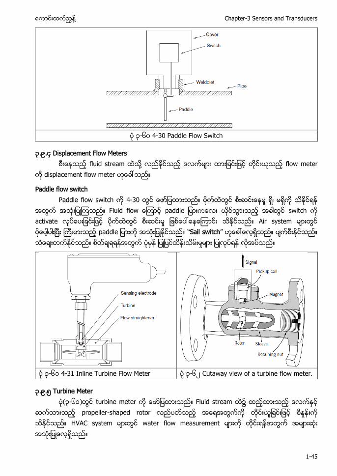
၃-၆၀ 4-30 Paddle Flow Switch
၃.၉.၄ Displacement Flow Meters fluid stream ႔ flow meter
displacement flow meter
Paddle flow switch Paddle flow switch 4-30
F u o p switch activate Air system p “Sail switch”
၃-၆၁ 4-31 Inline Turbine Flow Meter ၃-၆၂ Cutaway view of a turbine flow meter.
၃.၉.၅ Turbine Meter (၃-၆၁) turbine meter Fluid stream
propeller-shaped rotor HVAC system water flow measurement

HVAC Control and Building Automation Systems ႔
1-46
Magnetic sensor (metal rotor) Infrared light ၏ reflection Non-magnetic radio frequency impedance sensors
Turbine meter (bi-directional) Dual turbine meter accuracy Turbine (opposite directions) counter-rotating rotor swirling current (cancel out)
Turbine Meter High accuracy (.5% of rate) Clean water applications only High rangeability (up to 50:1) NIST Traceable Factory Calibration Compact design Low cost, Easy to install Fast response time In and out of line, under pressure Broad range of sizes Turbine Flowmeters Advantages Disadvanteages High Accuracy Only For Low Viscosities Suitable for Extreme Temperatures and Pressures
Moving Parts
Can Be Used On Gas or Liquid Sensitive to Flow Profile Pressure differential flowmeters Helical gear Oval gear Nutating disk Rotary Oscillating piston
၃.၉.၆ Target Meter
၃-၆၃ 4-32 Target Meter
႔ Chapter-3 Sensors and Transducers
1-47
(၃-၆၂) target meter Drag-force meter F o p flow rate Flow rate bending action stress
Strain-gauge stress (moving parts)
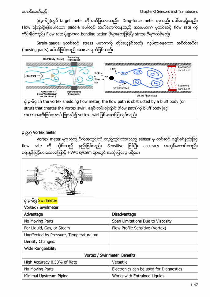
၃-၆၄ In the vortex shedding flow meter, the flow path is obstructed by a bluff body (or strut) that creates the vortex swirl. (flow path) bluff body o t
၃.၉.၇ Vortex meter Vortex meter ႔ sensor
flow rate t accuracy HVAC system
၃-၆၅ Swirlmeter Vortex / Swirlmeter Advantage Disadvantage No Moving Parts Span Limitations Due to Viscosity For Liquid, Gas, or Steam Flow Profile Sensitive (Vortex) Uneffected by Pressure, Temperature, or Density Changes.
Wide Rangeability Vortex / Swirlmeter Benefits
High Accuracy 0.50% of Rate Versatile No Moving Parts Electronics can be used for Diagnostics Minimal Upstream Piping Works with Entrained Liquids
HVAC Control and Building Automation Systems ႔
1-48
Measures Low Flows
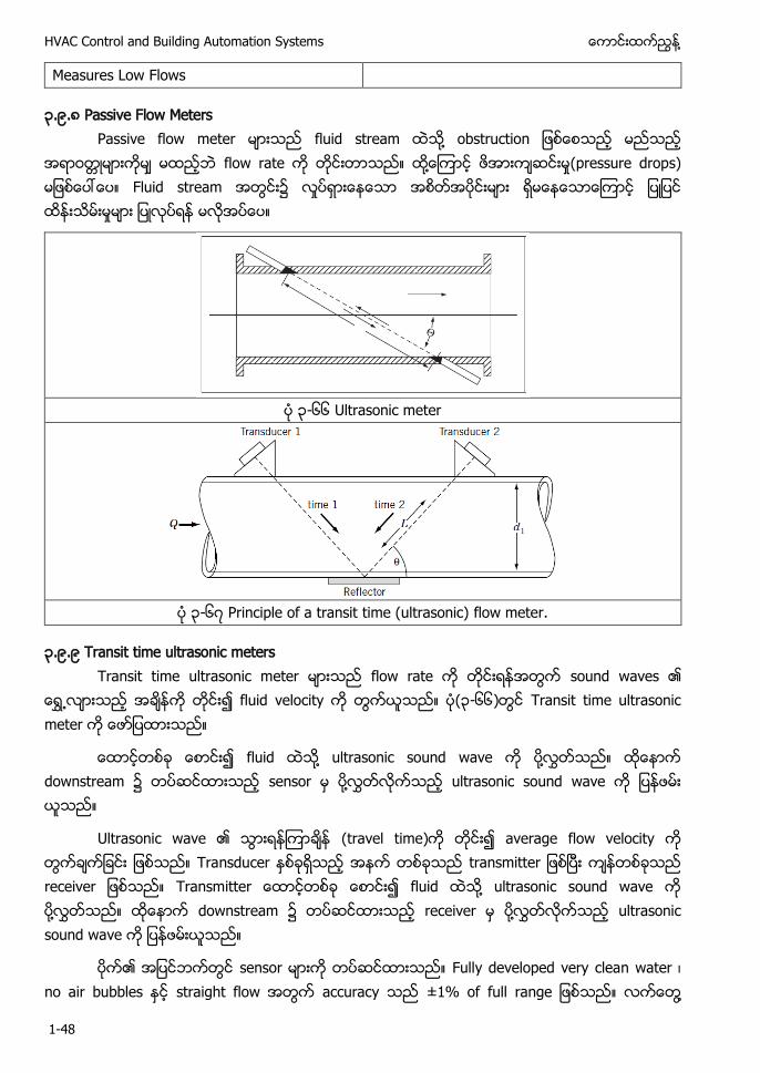
၃.၉.၈ Passive Flow Meters Passive flow meter fluid stream ႔ o t u t o
flow rate ႔ (pressure drops) Fluid stream
၃-၆၆ Ultrasonic meter
၃-၆၇ Principle of a transit time (ultrasonic) flow meter.
၃.၉.၉ Transit time ultrasonic meters Transit time ultrasonic meter flow rate sound waves ၏
fluid velocity (၃-၆၆) Transit time ultrasonic meter
fluid ႔ ultrasonic sound wave ႔ downstream sensor ႔ ultrasonic sound wave
Ultrasonic wave ၏ (travel time) average flow velocity Transducer t tt Transmitte fluid ႔ ultrasonic sound wave ႔ downstream receiver ႔ ultrasonic sound wave
၏ sensor Fully developed very clean water no air bubbles straight flow accuracy o u ႔
႔ Chapter-3 Sensors and Transducers
1-49
accuracy ±5% Piping dimensions fluid properties other practical limitation ႔ accuracy
Ultrasonic Flowmeter doppler time of flight ( ) Doppler effect, used for dirty, slurry type flows ( ) Transit time measurement, used for clean fluids Ultrasonic Flowmeters - Performance Considerations Reynolds number constraints Installed without process shut down Entrained gas or particles for doppler Straight upstream piping requirements Clean liquids for time of flight
Ultrasonic Flowmeters Advantages Disadvanteages
• No Moving Parts • For Liquids Only (limited gas) • Unobstructed Flow Passage • Flow Profile Dependent • Wide Rangeability • Errors Due To Deposits
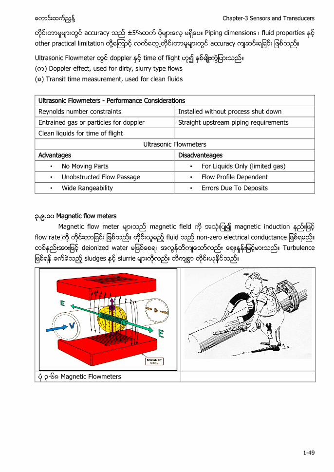
၃.၉.၁၀ Magnetic flow meters Magnetic flow meter magnetic field magnetic induction
flow rate fluid o - o t o u t deionized water Tu u sludges slurrie
၃-၆၈ Magnetic Flowmeters
HVAC Control and Building Automation Systems ႔
1-50
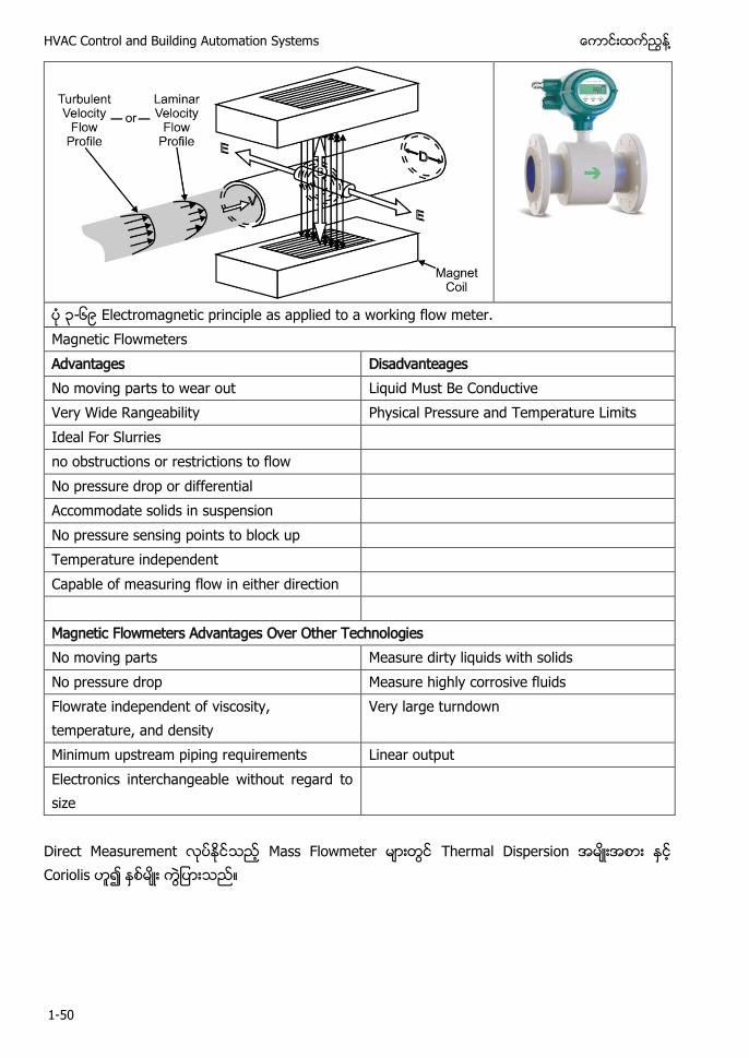
၃-၆၉ Electromagnetic principle as applied to a working flow meter. Magnetic Flowmeters Advantages Disadvanteages No moving parts to wear out Liquid Must Be Conductive Very Wide Rangeability Physical Pressure and Temperature Limits Ideal For Slurries no obstructions or restrictions to flow No pressure drop or differential Accommodate solids in suspension No pressure sensing points to block up Temperature independent Capable of measuring flow in either direction Magnetic Flowmeters Advantages Over Other Technologies No moving parts Measure dirty liquids with solids No pressure drop Measure highly corrosive fluids Flowrate independent of viscosity, temperature, and density
Very large turndown
Minimum upstream piping requirements Linear output Electronics interchangeable without regard to size
Direct Measurement Mass Flowmeter Thermal Dispersion Coriolis

႔ Chapter-3 Sensors and Transducers
1-51
၃.၉.၁၁ Mass Flow Meters Coriolis force meter angular momentum meter mass flow meter HVAC
mass flow meter Thermal anemometer ႔ hot-wire anemometer air flow measurement
၃-၇၀ 4-34 Thermal Anemometer
(၃-၇၀) thermal anemometer Air stream ႔ heated probe mass flow rate heated probe Probe temperature sensor electric resistance-heating element ႔
Heated probe 200°F ႔ electrical current velocity signal ၏ (air density)
thermal anemometer heating element temperature sensor Self-heated thermistor Temperature sensor upstream air density entering air temperature accuracy
Thermal anemometer ၏ pitot tube sensor air velocity Commercial model 500 fpm ±2% to ±3% accuracy 100 fpm ႔ accuracy ±20 fpm Anemometer velocity 150 to 5,000 fpm accuracy
Pitot sensor 400 fpm (0.01 inch wg) Pitot sensor velocities range ႔ VAV system thermal anemometer Thermal anemometer fan inlet
HVAC Control and Building Automation Systems ႔
1-52
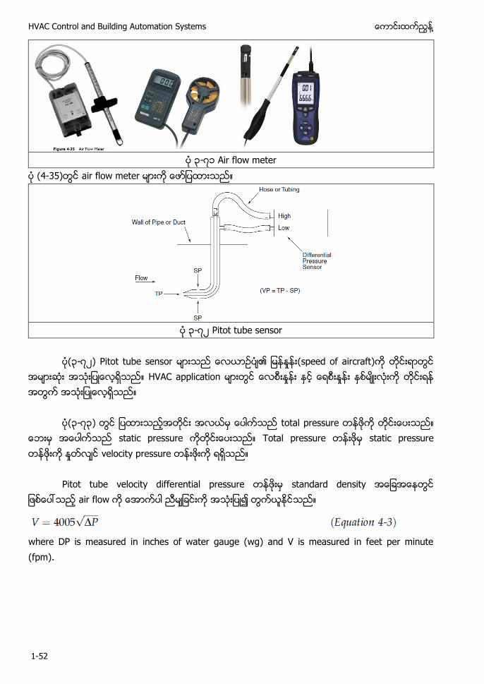
၃-၇၁ Air flow meter
(4-35) air flow meter
၃-၇၂ Pitot tube sensor
(၃-၇၂) Pitot tube sensor ၏ (speed of aircraft)
HVAC application
(၃-၇၃) total pressure static pressure Total pressure static pressure velocity pressure
Pitot tube velocity differential pressure standard density air flow
where DP is measured in inches of water gauge (wg) and V is measured in feet per minute (fpm).

႔ Chapter-3 Sensors and Transducers
1-53
၃-၇၃ Figure 4-37 Air Flow Measuring Station
Figure 4-37 shows an air flow measuring station (FMS) commonly used in duct applications. In large ducts, the FMS is composed of an array of pitot sampling tubes the pressure signals of which are averaged. This signal is fed to a square root extractor, which is a transmitter that converts the differential pressure signal into a velocity signal. (With digital control systems, this calculation can be made in software with improved accuracy over the use of a square root extractor.) The velocity measured in this way is an approximate average of duct velocity, but it is not a precise average because pressure and velocity are not proportional (the average of the square of velocity is not equal to the average of the velocity). Where fan air flow rate measurement is required, the preferred location of the pitot sensor is in the inlet of the fan. Two arrangements are available. The first, which can be used with almost any fan, has two bars with multiple velocity pressure and static pressure ports mounted on either side of the fan axis. The second, much less common arrangement has multiple pinhole pressure taps that are built into the fan inlet by the fan manufacturer. Differential pressure is measured from the outer point of the inlet to the most constricted point, much like a Venturi meter. Locating the air flow sensor in the fan inlet has many advantages compared to a duct mounted pitot array. First, air flow is generally stable in the inlet (except when inlet vanes are used, in which case this location is not recommended) and velocities are high, which increases accuracy because the differential pressure signal will be high. Even where inlet vanes are used, a location in the mixed air plenum space could be found. This location also reduces costs because the sensor array is smaller than the array required in a duct. Perhaps the most important advantage of this location is that it obviates the need to provide long straight duct sections required for the duct mounted array. The space needed for these duct sections seldom seems to be available in modern HVAC applications where the operating space occupied by HVAC systems is heavily
HVAC Control and Building Automation Systems ႔
1-54
scrutinized by the owner and architect, reduced to its smallest area possible, and consciously minimized.
၃.၉.၁၂ Displacement Flow Meters: air stream ႔ flow meter
Displacement flow meter
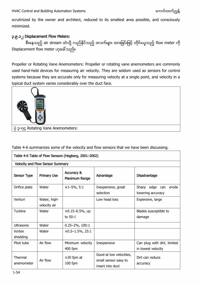
Propeller or Rotating Vane Anemometers: Propeller or rotating vane anemometers are commonly used hand-held devices for measuring air velocity. They are seldom used as sensors for control systems because they are accurate only for measuring velocity at a single point, and velocity in a typical duct system varies considerably over the duct face.
၃-၇၄ Rotating Vane Anemometers:
Table 4-6 summarizes some of the velocity and flow sensors that we have been discussing.
Table 4-6 Table of Flow Sensors (Hegberg, 2001–2002)
Velocity and Flow Sensor Summary Sensor Type
Primary Use
Accuracy & Maximum Range
Advantage
Disadvantage
Orifice plate Water ±1–5%, 5:1 Inexpensive, great selection
Sharp edge can erode lowering accuracy
Venturi Water, high-velocity air
Low head loss Expensive, large
Turbine Water ±0.15–0.5%, up to 50:1
Blades susceptible to damage
Ultrasonic Water 0.25–2%, 100:1 Vortex shedding
Water ±0.5–1.5%, 25:1
Pitot tube Air flow Minimum velocity 400 fpm
Inexpensive Can plug with dirt, limited in lowest velocity
Thermal anemometer
Air flow ±20 fpm at 100 fpm
Good at low velocities, small sensor easy to insert into duct
Dirt can reduce accuracy
႔ Chapter-3 Sensors and Transducers
1-55
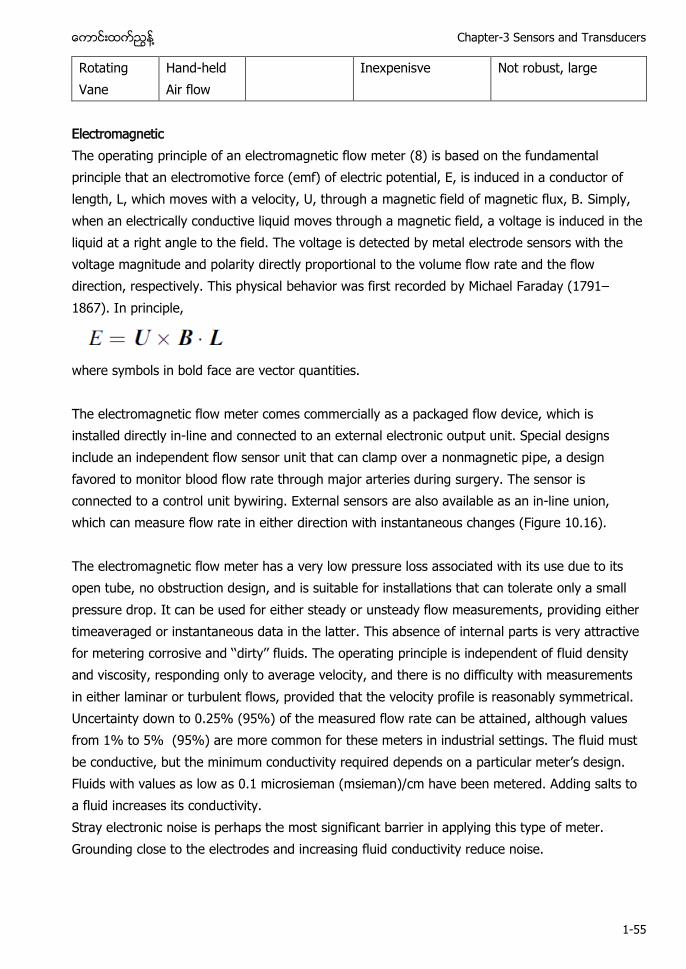
Rotating Vane
Hand-held Air flow
Inexpenisve Not robust, large
Electromagnetic The operating principle of an electromagnetic flow meter (8) is based on the fundamental principle that an electromotive force (emf) of electric potential, E, is induced in a conductor of length, L, which moves with a velocity, U, through a magnetic field of magnetic flux, B. Simply, when an electrically conductive liquid moves through a magnetic field, a voltage is induced in the liquid at a right angle to the field. The voltage is detected by metal electrode sensors with the voltage magnitude and polarity directly proportional to the volume flow rate and the flow direction, respectively. This physical behavior was first recorded by Michael Faraday (1791–1867). In principle,
where symbols in bold face are vector quantities. The electromagnetic flow meter comes commercially as a packaged flow device, which is installed directly in-line and connected to an external electronic output unit. Special designs include an independent flow sensor unit that can clamp over a nonmagnetic pipe, a design favored to monitor blood flow rate through major arteries during surgery. The sensor is connected to a control unit bywiring. External sensors are also available as an in-line union, which can measure flow rate in either direction with instantaneous changes (Figure 10.16). The electromagnetic flow meter has a very low pressure loss associated with its use due to its open tube, no obstruction design, and is suitable for installations that can tolerate only a small pressure drop. It can be used for either steady or unsteady flow measurements, providing either timeaveraged or instantaneous data in the latter. This absence of internal parts is very attractive for t o o ‘‘ t ’’ u . T op t p p p t o luid density and viscosity, responding only to average velocity, and there is no difficulty with measurements in either laminar or turbulent flows, provided that the velocity profile is reasonably symmetrical. Uncertainty down to 0.25% (95%) of the measured flow rate can be attained, although values from 1% to 5% (95%) are more common for these meters in industrial settings. The fluid must be conductive, but the u o u t t u p o p t u t ’ . Fluids with values as low as 0.1 microsieman (msieman)/cm have been metered. Adding salts to a fluid increases its conductivity. Stray electronic noise is perhaps the most significant barrier in applying this type of meter. Grounding close to the electrodes and increasing fluid conductivity reduce noise.

HVAC Control and Building Automation Systems ႔
1-56
၃.၁၀ CALIBRATION METHODOLOGY CALIBRATION
• It’ t p o u o t t o t u o t u o parision with the standard ones.
• The standard of device with which comparison is made is called a standard instrument. • The instrument which is unknown and is to be calibrated is called test instrument. • In calibration test instrument is compared with the standard instrument.
DIRECT COMPARISON
• METER CALIBRATION
• GENERATOR CALIBRATION
• TRANSDUCER CALIBRATION
INDIRECT COMPARISON • METER CALIBRATION • GENERATOR CALIBRATION • TRANSDUCER CALIBRATION
Contents ၃.၁ Classification Of Instruments ............................................................................................. 1
၃.၂ (Definition of Terminology) ............................................................... 5
၃.၃ Sensor Performance Characteristic ................................................................................... 10
၃.၄ Selection Requirements ................................................................................................... 11
၃.၅ Classification of Error ...................................................................................................... 13
၃.၆ Temperature Sensors ...................................................................................................... 14
၃.၆.၁ Principles of Temperature Measurement ............................................................................................ 15
၃.၆.၂ Thermocouple .................................................................................................................................. 17
၃.၆.၃ Thermistors ..................................................................................................................................... 19
၃.၆.၄ Resistance Temperature Detectors (RTDs) ......................................................................................... 20
၃.၆.၅ Integrated Circuit Temperature Sensors ............................................................................................ 24
၃.၆.၆ Summary of temperature sensors ..................................................................................................... 26
၃.၆.၇ T p tu o ’ M u o ............................................................................................ 27
၃.၇ Moisture Sensors ............................................................................................................ 27
႔ Chapter-3 Sensors and Transducers
1-57
၃.၇.၁ Relative Humidity Sensors ................................................................................................................ 28
၃.၇.၂ Resistance-type humidity sensors ...................................................................................................... 29
၃.၇.၃ Capacitance-Type Humidity Sensors .................................................................................................. 29
၃.၇.၄ Lithium Chloride Dew-point Sensors: ................................................................................................. 30
၃.၇.၅ Chilled-Mirror Dew-point Sensors: ..................................................................................................... 30
၃.၇.၆ Psychrometers ................................................................................................................................. 31
၃.၈ Pressure Sensors ............................................................................................................ 33
၃.၈.၁ Summary of pressure sensors for BAS applications ............................................................................. 35
၃.၈.၂ Mechanical Pressure Gauges: ............................................................................................................ 35
၃.၈.၃ Diaphragm sensor ............................................................................................................................ 36
၃.၈.၄ Potentiometer .................................................................................................................................. 37
၃.၈.၅ Electrical Pressure Guages: ............................................................................................................... 38
၃.၈. ၆ Capacitance pressure detector ......................................................................................................... 38
၃.၉ Flow Sensors and Meters ................................................................................................. 39
၃.၉.၁ Differential Pressure Flow Meters ...................................................................................................... 41
၃.၉.၂ Orifice Meter .................................................................................................................................... 41
၃.၉.၃ Venturi Meter ................................................................................................................................... 42
၃.၉.၄ Displacement Flow Meters ................................................................................................................ 45
၃.၉.၅ Turbine Meter .................................................................................................................................. 45
၃.၉.၆ Target Meter .................................................................................................................................... 46
၃.၉.၇ Vortex meter.................................................................................................................................... 47
၃.၉.၈ Passive Flow Meters ......................................................................................................................... 48
၃.၉.၉ Transit time ultrasonic meters ........................................................................................................... 48
၃.၉.၁၀ Magnetic flow meters ..................................................................................................................... 49
၃.၉.၁၁ Mass Flow Meters ........................................................................................................................... 51
၃.၉.၁၂ Displacement Flow Meters: ............................................................................................................. 54
Coriolis Advantages Disadvanteages
• Direct Mass Measurement • High Purchase Price
HVAC Control and Building Automation Systems ႔
1-58
• High Accuracy • High Installation Cost • Additional Density Measurement • Size Limitations • Uneffected By Flow Profile • Vibration Sensitive