Embed Size (px)
Citation preview
Sensors
Lecture is based on material from Robotic Explorations: A Hands-on Introduction to Engineering, Fred Martin, Prentice Hall, 2001.
Copyright Prentice Hall, 2001 2
Outline
• Sensor Interfacing
• Switch Sensors
• Resistive Position Sensors
• Light Sensor Circuits
• Reflective Optosensors
• Break-Beam Sensors
• Shaft Encoding
Copyright Prentice Hall, 2001 3
• Sensors: Read Chapter 3 of Robotic Explorations (textbook)
Assignment
Copyright Prentice Hall, 2001 4
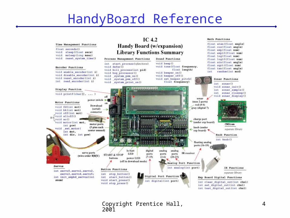
HandyBoard Reference
Copyright Prentice Hall, 2001 5
Switch Sensors
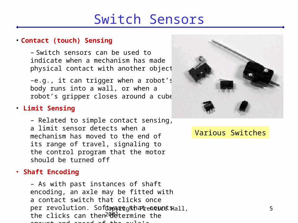
• Contact (touch) Sensing
– Switch sensors can be used to indicate when a mechanism has made physical contact with another object
–e.g., it can trigger when a robot’s body runs into a wall, or when a robot’s gripper closes around a cube
• Limit Sensing
– Related to simple contact sensing, a limit sensor detects when a mechanism has moved to the end of its range of travel, signaling to the control program that the motor should be turned off
• Shaft Encoding
– As with past instances of shaft encoding, an axle may be fitted with a contact switch that clicks once per revolution. Software that counts the clicks can then determine the amount and speed of the axle’s rotation.
Various Switches
Copyright Prentice Hall, 2001 6
Switch Sensors
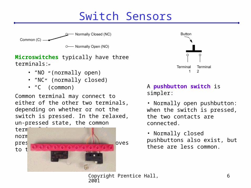
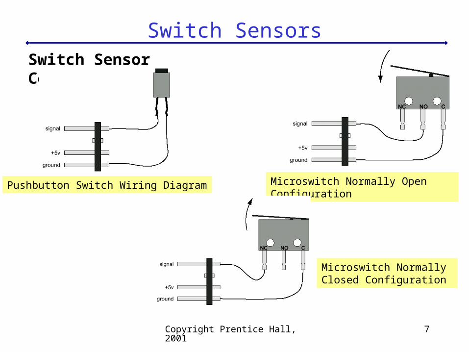
Microswitches typically have three terminals:
• “NO” (normally open)• “NC” (normally closed)• “C” (common)
Common terminal may connect to either of the other two terminals, depending on whether or not the switch is pressed. In the relaxed, un-pressed state, the common terminal is connected to the normally closed contact; when pressed, the common terminal moves to the normally open contact.
A pushbutton switch is simpler:
• Normally open pushbutton: when the switch is pressed, the two contacts are connected.
• Normally closed pushbuttons also exist, but these are less common.
Copyright Prentice Hall, 2001 7
Switch SensorsSwitch Sensor Construction
Microswitch Normally Open ConfigurationPushbutton Switch Wiring Diagram
Microswitch Normally Closed Configuration
Copyright Prentice Hall, 2001 8
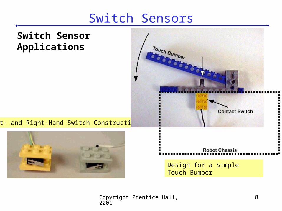
Switch SensorsSwitch Sensor Applications
Left- and Right-Hand Switch Construction
Design for a Simple Touch Bumper
Copyright Prentice Hall, 2001 9
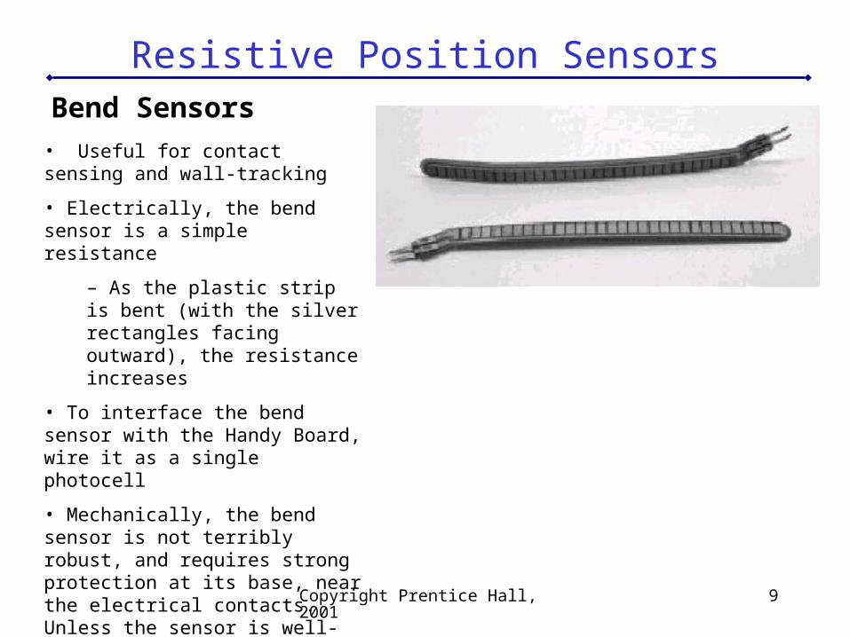
Resistive Position SensorsBend Sensors
• Useful for contact sensing and wall-tracking
• Electrically, the bend sensor is a simple resistance
– As the plastic strip is bent (with the silver rectangles facing outward), the resistance increases
• To interface the bend sensor with the Handy Board, wire it as a single photocell
• Mechanically, the bend sensor is not terribly robust, and requires strong protection at its base, near the electrical contacts. Unless the sensor is well-protected from direct forces, it will fail over time.
Copyright Prentice Hall, 2001 10
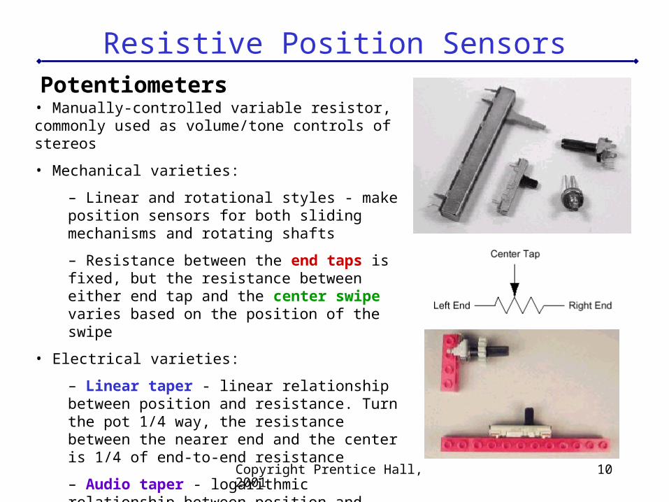
Resistive Position SensorsPotentiometers
• Manually-controlled variable resistor, commonly used as volume/tone controls of stereos
• Mechanical varieties:
– Linear and rotational styles - make position sensors for both sliding mechanisms and rotating shafts
– Resistance between the end taps is fixed, but the resistance between either end tap and the center swipe varies based on the position of the swipe
• Electrical varieties:
– Linear taper - linear relationship between position and resistance. Turn the pot 1/4 way, the resistance between the nearer end and the center is 1/4 of end-to-end resistance
– Audio taper - logarithmic relationship between position and resistance. At one end, 1/4 turn would swipe over a small bit of total resistance range, while at the other end, 1/4 turn would be most of the range
Copyright Prentice Hall, 2001 11
Resistive Position SensorsPotentiometers
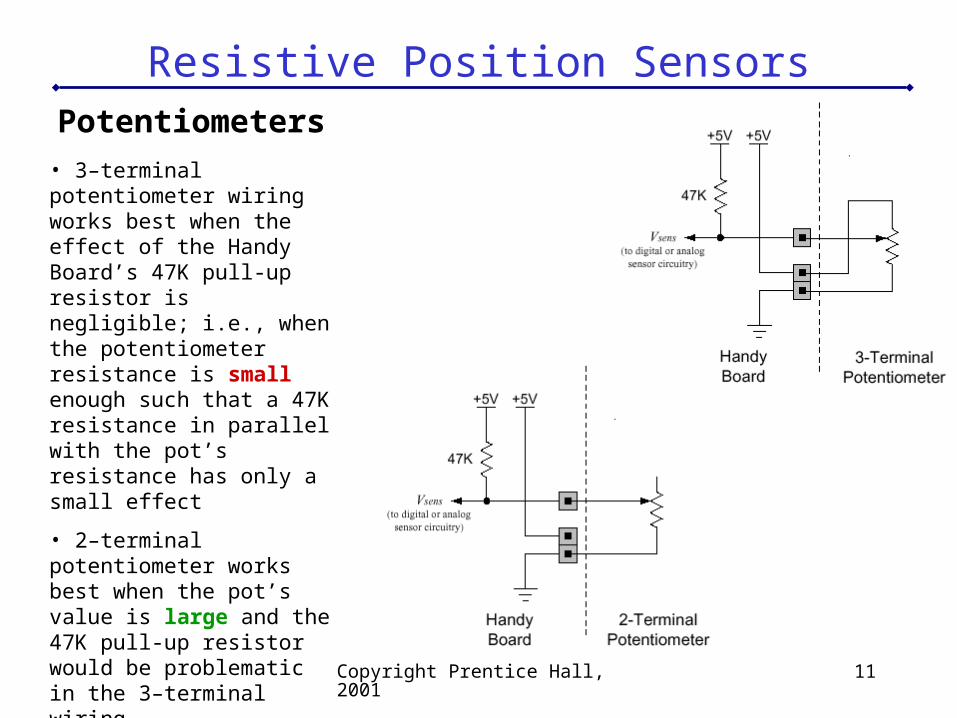
• 3–terminal potentiometer wiring works best when the effect of the Handy Board’s 47K pull-up resistor is negligible; i.e., when the potentiometer resistance is small enough such that a 47K resistance in parallel with the pot’s resistance has only a small effect
• 2–terminal potentiometer works best when the pot’s value is large and the 47K pull-up resistor would be problematic in the 3–terminal wiring
Light Sensor Circuits
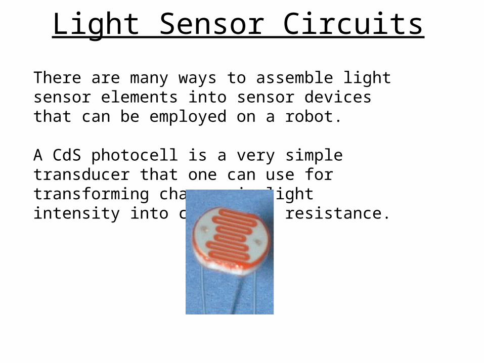
There are many ways to assemble light sensor elements into sensor devices that can be employed on a robot.
A CdS photocell is a very simple transducer that one can use for transforming changes in light intensity into changes in resistance.
How does a CdS photocell work?
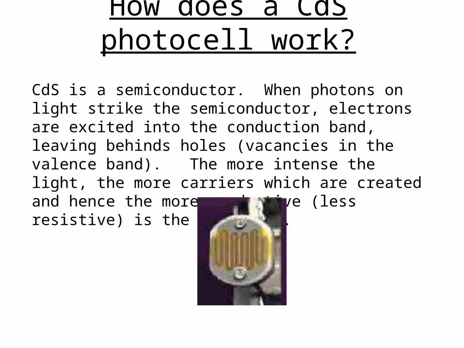
CdS is a semiconductor. When photons on light strike the semiconductor, electrons are excited into the conduction band, leaving behinds holes (vacancies in the valence band). The more intense the light, the more carriers which are created and hence the more conductive (less resistive) is the photocell.
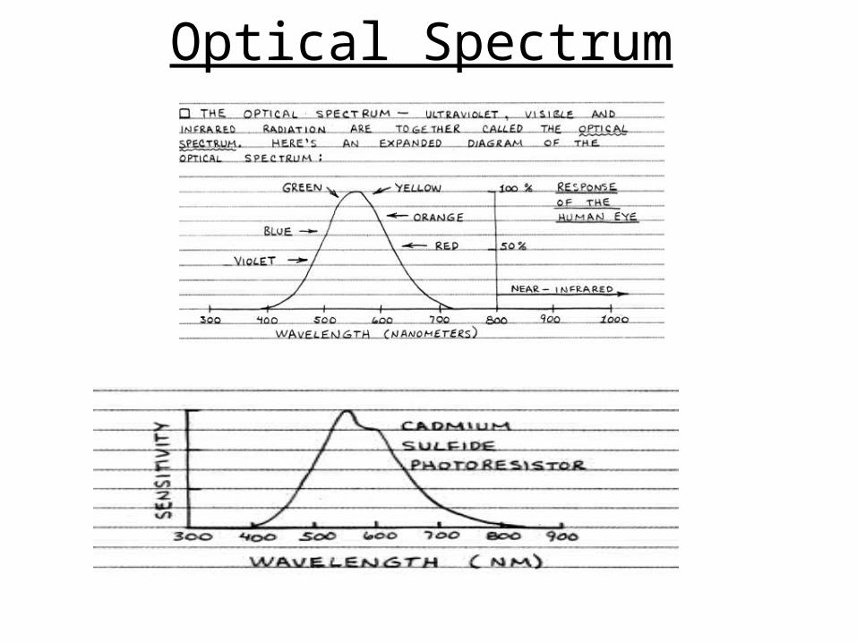
Optical Spectrum
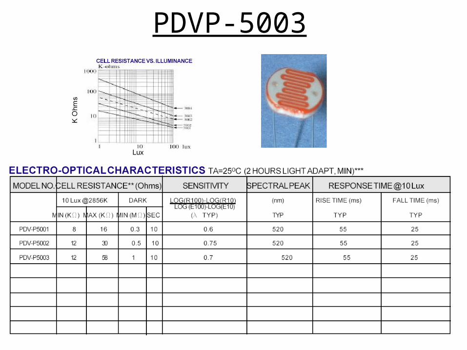
PDVP-5003
Copyright Prentice Hall, 2001 16
Light Sensor CircuitsSingle Photocell Circuit
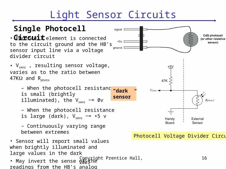
Photocell Voltage Divider Circuit
• Photocell element is connected to the circuit ground and the HB’s sensor input line via a voltage divider circuit
• Vsens , resulting sensor voltage, varies as to the ratio between 47K and Rphoto
– When the photocell resistance is small (brightly illuminated), the Vsens ~= 0v
– When the photocell resistance is large (dark), Vsens ~= +5 v
– Continuously varying range between extremes
• Sensor will report small values when brightly illuminated and large values in the dark
• May invert the sense of the readings from the HB’s analog ports:
int light(int port) {return 255 - analog(port);}
“darksensor”
Copyright Prentice Hall, 2001 17
Light Sensor CircuitsSingle Photocell Circuit
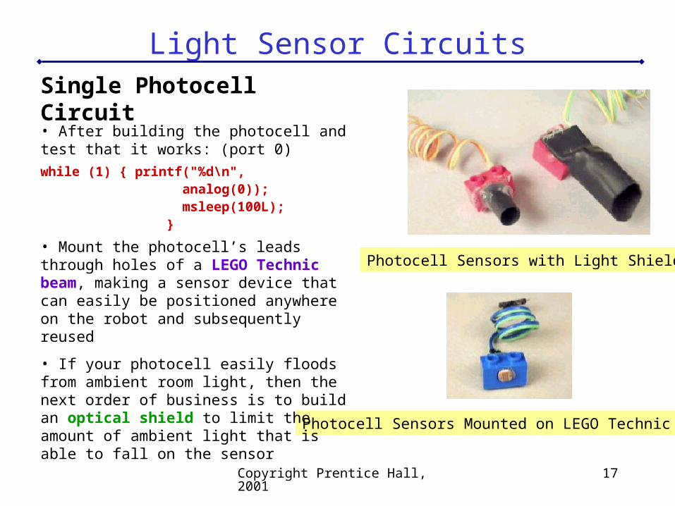
Photocell Sensors Mounted on LEGO Technic Beam
Photocell Sensors with Light Shields
• After building the photocell and test that it works: (port 0)
while (1) { printf("%d\n", analog(0)); msleep(100L); }
• Mount the photocell’s leads through holes of a LEGO Technic beam, making a sensor device that can easily be positioned anywhere on the robot and subsequently reused
• If your photocell easily floods from ambient room light, then the next order of business is to build an optical shield to limit the amount of ambient light that is able to fall on the sensor
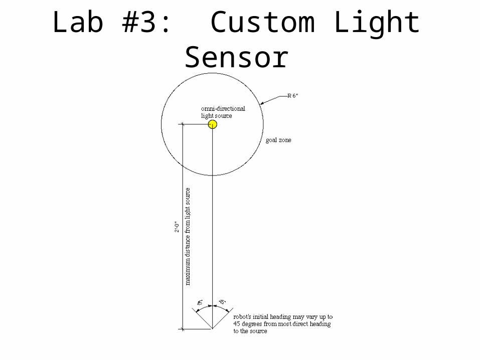
Lab #3: Custom Light Sensor
Evaluation• Behavior: 50 points
– 10 points for waking up when light is turned on.– 10 points for pointing in the direction of the light source.– 10 points for reaching the goal area.– 10 points for correctly stopping in the goal area.– Up to 10 points for exceeding expectations: for example, working at a
distance significantly greater than 24", using only the custom sensor, completing the task in under 10 seconds, capable of following slowly moving light source etc.
• 40 points: Lab report.– 10 points for grammar, spelling, etc.– 10 points for clarity of writing.– 10 points for quality of design and justifying all design decisions.– 10 points for presenting and analyzing data taken during
testing/calibration.• 10 points: Team Meeting Notes.
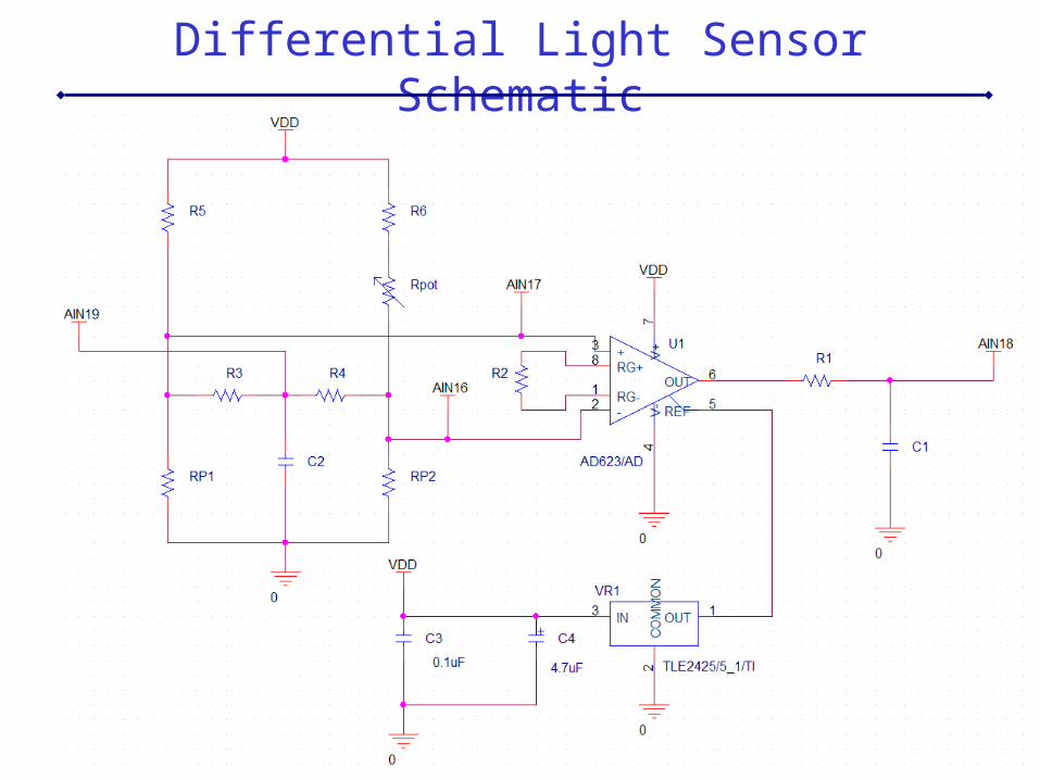
Differential Light Sensor Schematic
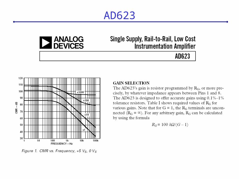
AD623
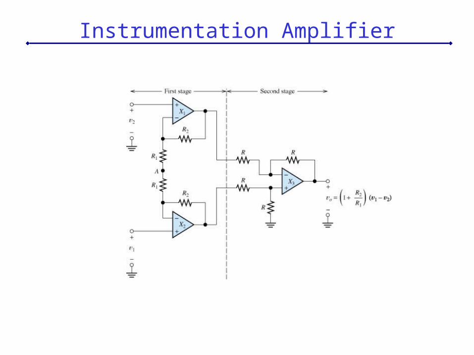
Instrumentation Amplifier
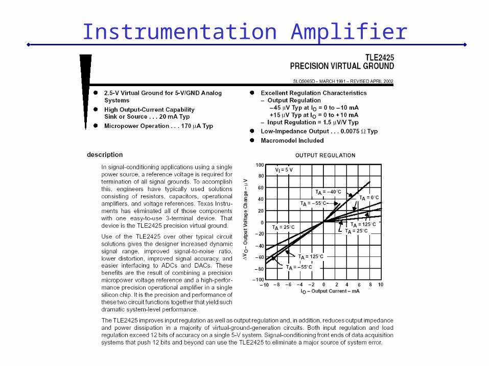
Instrumentation Amplifier

Collecting Sensor Data
void collect_data(){ int i;
for (i= 0; i< SAMPLES; i++) { data[i]= analog(0); /* to slow down capture rate, add msleep here
*/ }}
void dump_data(){ int i;
for (i= 0; i< SAMPLES; i++) { printdec(data[i]); serial_putchar(10); /* line feed */ serial_putchar(13); /* carriage return */ }}
/* datacoll.c data collection and printing
requires printdec.c, serialio.c*/
int SAMPLES=1000;char data[1000];
void main(){ disable_pcode_serial();
printf("press Start to collect data\n"); start_press(); collect_data(); beep();
printf("press Start to dump data\n"); start_press(); dump_data(); beep();
printf("done.\n");}
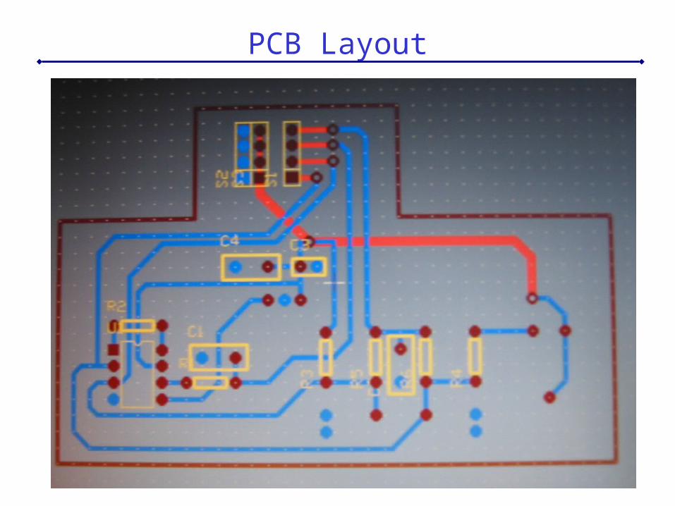
PCB Layout
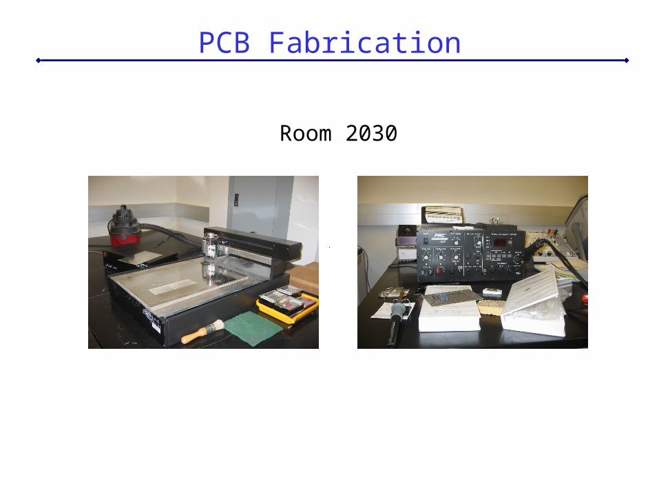
PCB Fabrication
Room 2030
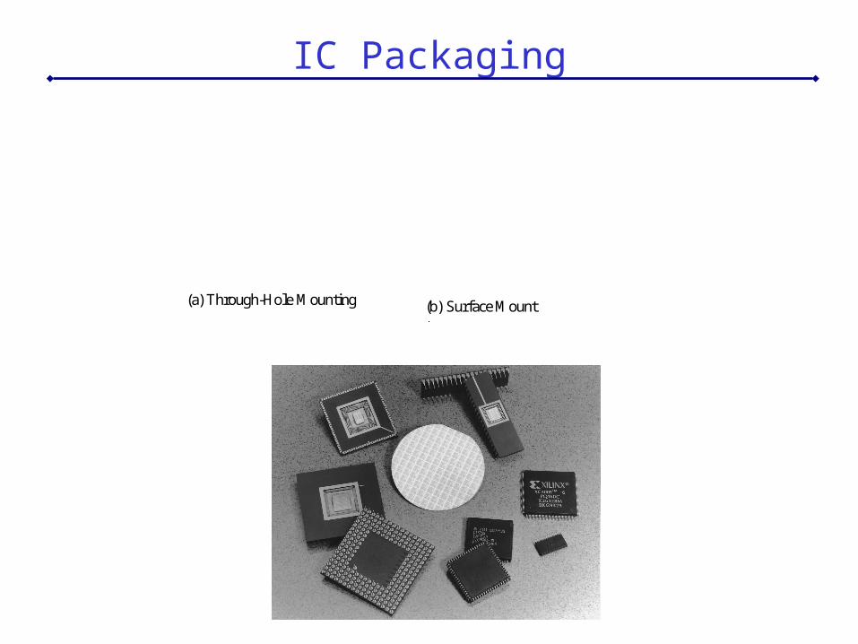
IC Packaging
(a) Through-Hole Mounting (b) Surface Mount
Copyright Prentice Hall, 2001 28
Reflective Optosensors
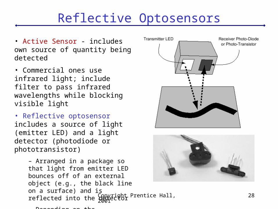
• Active Sensor - includes own source of quantity being detected
• Commercial ones use infrared light; include filter to pass infrared wavelengths while blocking visible light
• Reflective optosensor includes a source of light (emitter LED) and a light detector (photodiode or phototransistor)
– Arranged in a package so that light from emitter LED bounces off of an external object (e.g., the black line on a surface) and is reflected into the detector
– Depending on the reflectivity of the surface, more or less of the transmitted light is reflected into the detector
– Quantity of light is reported by the sensor
Copyright Prentice Hall, 2001 29
Reflective Optosensors
ApplicationsObject detection. Reflectance sensors may be used to measure the presence of an object in the sensor’s field of view. In addition to simply detecting the presence of the object, the data from a reflectance sensor may be used to indicate the object’s distance from the sensor. These reading are dependent on the reflectivity of the object, among other things—a highly reflective object that is farther away may yield a signal as strong as a less reflective object that is closer.
Surface feature detection. Reflective optosensors are great for detecting features painted, taped, or otherwise marked onto the floor. Line-following using a reflective sensor is a typical robot activity.
Wall tracking. Related the object detection category, this application treats the wall as a continuous obstacle and uses the reflective sensor to indicate distance from the wall.
Rotational shaft encoding. Using a pie-shaped encoder wheel, the reflectance sensor can measure the rotation of a shaft (angular position and velocity).
Barcode decoding. Reflectance sensors can be used to decode information from barcode markers placed in the robot’s environment.
Copyright Prentice Hall, 2001 30
Reflective Optosensors
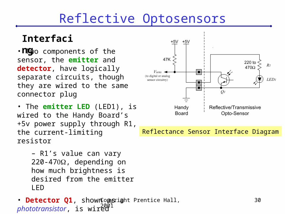
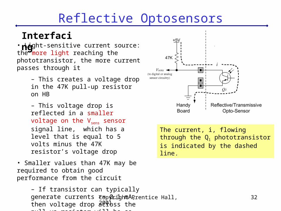
Interfacing• Two components of the sensor, the emitter and detector, have logically separate circuits, though they are wired to the same connector plug
• The emitter LED (LED1), is wired to the Handy Board’s +5v power supply through R1, the current-limiting resistor
– R1’s value can vary 220-47, depending on how much brightness is desired from the emitter LED
• Detector Q1, shown as a phototransistor, is wired between ground and the sensor signal line—just like a photocell
Reflectance Sensor Interface Diagram
Copyright Prentice Hall, 2001 31
Reflective Optosensors
Photocells vs. Phototransistors
How do you choose one type of device rather than the other?
• Photocells are easy to work with, because electrically they are just resistors, but their response time is slow compared to the photodiode or phototransistor’s semiconductor junction. This means photocells are suitable for detecting levels of ambient light, or acting as break-beam sensors in low frequency applications (e.g., detecting when an object is between two fingers of a robot gripper).
• For applications such as shaft encoding, the rapid response time of the photodiode or phototransistor is required. Also, these devices are more sensitive to small levels of light, which allows the illumination source to be a simple LED element.
Copyright Prentice Hall, 2001 32
Reflective OptosensorsInterfacing
• Light-sensitive current source: the more light reaching the phototransistor, the more current passes through it
– This creates a voltage drop in the 47K pull-up resistor on HB
– This voltage drop is reflected in a smaller voltage on the Vsens sensor signal line, which has a level that is equal to 5 volts minus the 47K resistor’s voltage drop
• Smaller values than 47K may be required to obtain good performance from the circuit
– If transistor can typically generate currents >= 0.1 mA, then voltage drop across the pull-up resistor will be so high as to reduce Vsens to zero
– Solution is to wire a smaller pull-up resistor with the sensor itself
The current, i, flowing through the Q1 phototransistor is indicated by the dashedline.
Copyright Prentice Hall, 2001 33
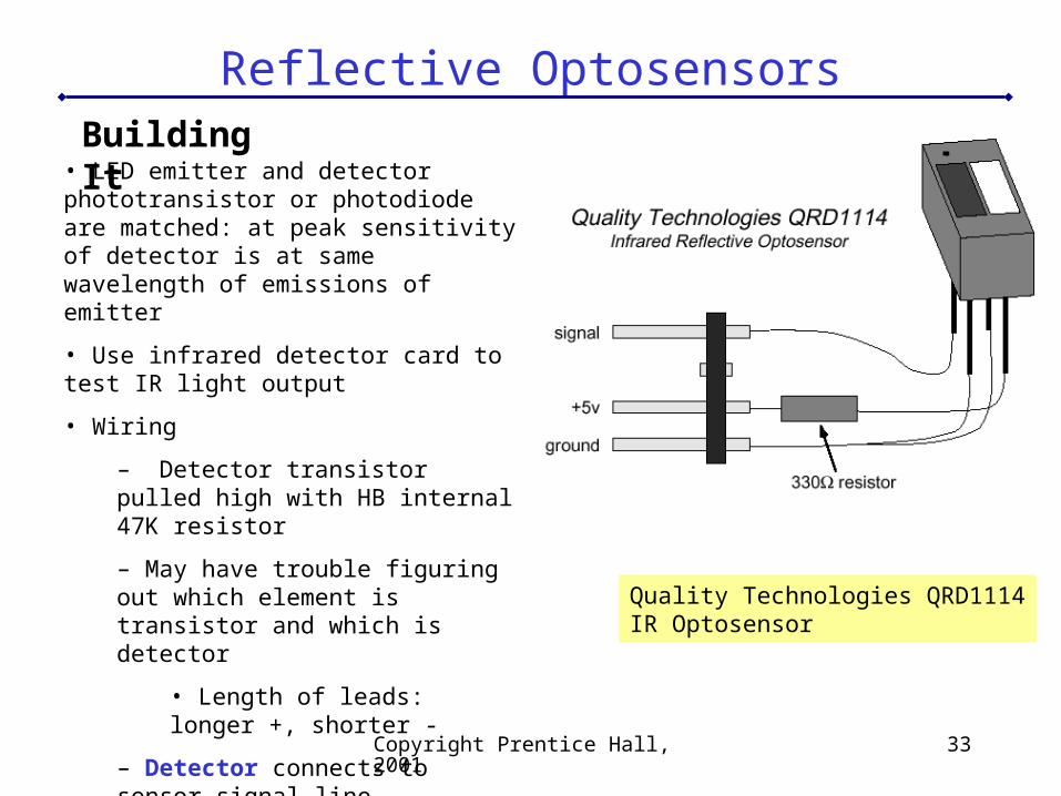
Reflective OptosensorsBuilding It
• LED emitter and detector phototransistor or photodiode are matched: at peak sensitivity of detector is at same wavelength of emissions of emitter
• Use infrared detector card to test IR light output
• Wiring
– Detector transistor pulled high with HB internal 47K resistor
– May have trouble figuring out which element is transistor and which is detector
• Length of leads: longer +, shorter -
– Detector connects to sensor signal line
– Emitter LED connects through 330K resistor to +5v supply (constantly on)
Quality Technologies QRD1114IR Optosensor
Copyright Prentice Hall, 2001 34
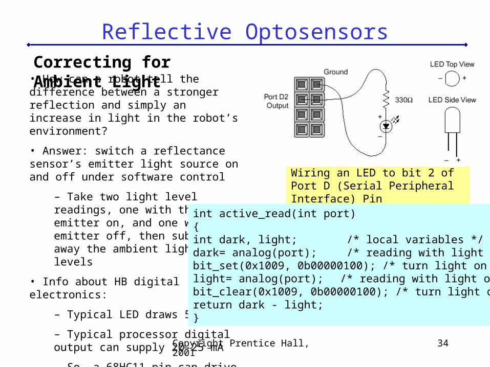
Reflective OptosensorsCorrecting for Ambient Light
• How can a robot tell the difference between a stronger reflection and simply an increase in light in the robot’s environment?
• Answer: switch a reflectance sensor’s emitter light source on and off under software control
– Take two light level readings, one with the emitter on, and one with the emitter off, then subtract away the ambient light levels
• Info about HB digital electronics:
– Typical LED draws 5-20 mA
– Typical processor digital output can supply 20-25 mA
– So, a 68HC11 pin can drive 1-5 LEDs
Wiring an LED to bit 2 of Port D (Serial Peripheral Interface) Pin
int active_read(int port){int dark, light; /* local variables */dark= analog(port); /* reading with light off */bit_set(0x1009, 0b00000100); /* turn light on */light= analog(port); /* reading with light on */bit_clear(0x1009, 0b00000100); /* turn light off */return dark - light;}
Copyright Prentice Hall, 2001 35
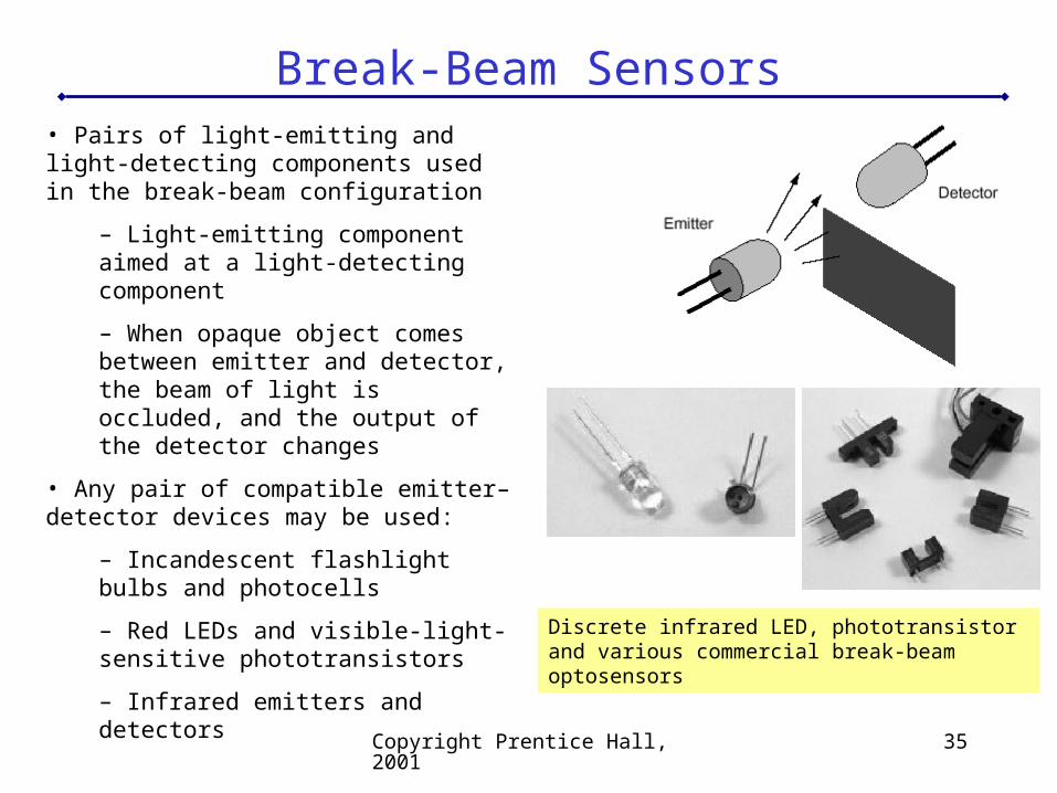
Break-Beam Sensors• Pairs of light-emitting and light-detecting components used in the break-beam configuration
– Light-emitting component aimed at a light-detecting component
– When opaque object comes between emitter and detector, the beam of light is occluded, and the output of the detector changes
• Any pair of compatible emitter–detector devices may be used:
– Incandescent flashlight bulbs and photocells
– Red LEDs and visible-light-sensitive phototransistors
– Infrared emitters and detectors Discrete infrared LED, phototransistor and various commercial break-beam optosensors
Copyright Prentice Hall, 2001 36
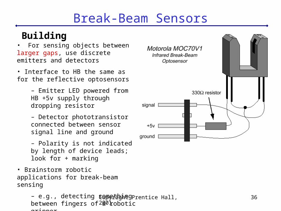
Break-Beam SensorsBuilding
• For sensing objects between larger gaps, use discrete emitters and detectors
• Interface to HB the same as for the reflective optosensors
– Emitter LED powered from HB +5v supply through dropping resistor
– Detector phototransistor connected between sensor signal line and ground
– Polarity is not indicated by length of device leads; look for + marking
• Brainstorm robotic applications for break-beam sensing
– e.g., detecting something between fingers of a robotic gripper
Copyright Prentice Hall, 2001 37
Shaft Encoding
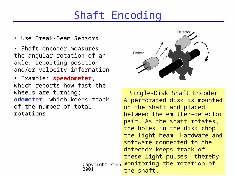
• Use Break-Beam Sensors
• Shaft encoder measures the angular rotation of an axle, reporting position and/or velocity information
• Example: speedometer, which reports how fast the wheels are turning; odometer, which keeps track of the number of total rotations Single-Disk Shaft Encoder
A perforated disk is mounted on the shaft and placed between the emitter–detector pair. As the shaft rotates, the holes in the disk chop the light beam. Hardware and software connected to the detector keeps track of these light pulses, thereby monitoring the rotation of the shaft.
Copyright Prentice Hall, 2001 38
Shaft Encoding
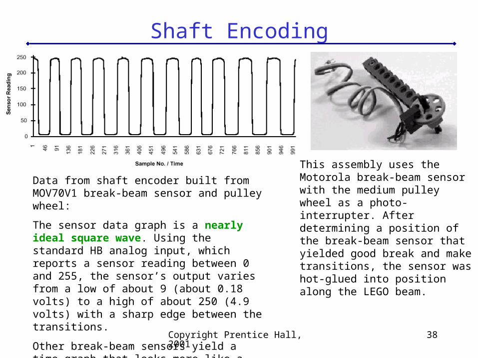
Data from shaft encoder built from MOV70V1 break-beam sensor and pulley wheel:
The sensor data graph is a nearly ideal square wave. Using the standard HB analog input, which reports a sensor reading between 0 and 255, the sensor’s output varies from a low of about 9 (about 0.18 volts) to a high of about 250 (4.9 volts) with a sharp edge between the transitions.
Other break-beam sensors yield a time graph that looks more like a sine wave.
This assembly uses the Motorola break-beam sensor with the medium pulley wheel as a photo-interrupter. After determining a position of the break-beam sensor that yielded good break and make transitions, the sensor was hot-glued into position along the LEGO beam.
Copyright Prentice Hall, 2001 39
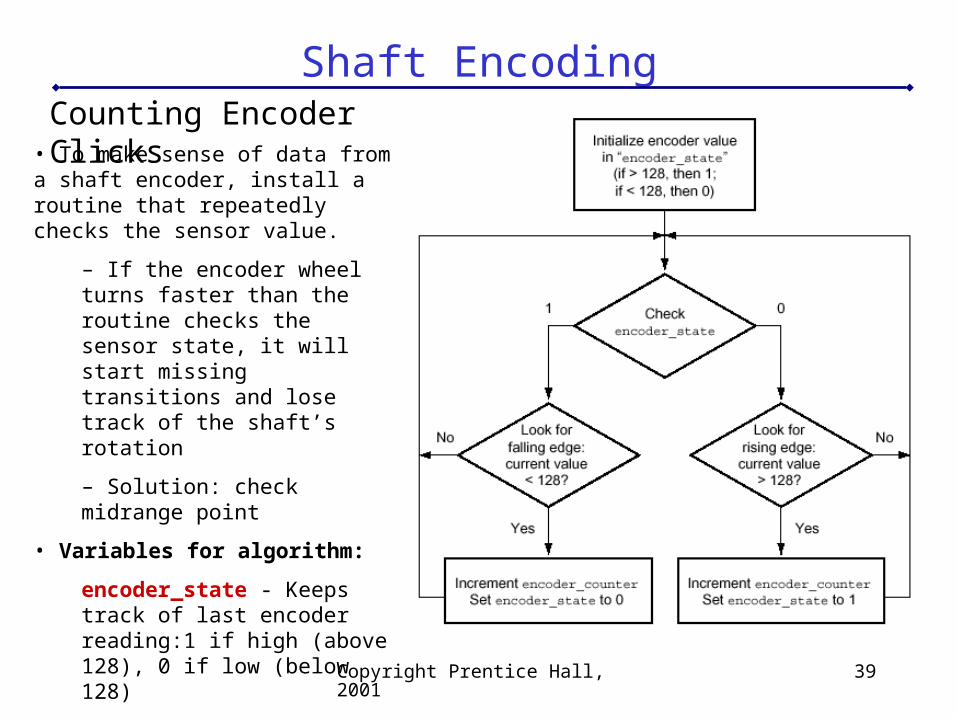
Shaft EncodingCounting Encoder Clicks
• To make sense of data from a shaft encoder, install a routine that repeatedly checks the sensor value.
– If the encoder wheel turns faster than the routine checks the sensor state, it will start missing transitions and lose track of the shaft’s rotation
– Solution: check midrange point
• Variables for algorithm:
encoder_state - Keeps track of last encoder reading:1 if high (above 128), 0 if low (below 128)
encoder_counter - Keeps running total of encoder “clicks”
Copyright Prentice Hall, 2001 40
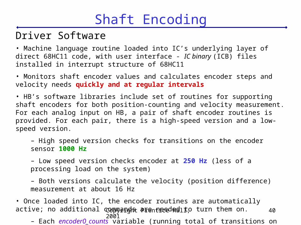
Shaft EncodingDriver Software• Machine language routine loaded into IC’s underlying layer of direct 68HC11 code, with user interface - IC binary (ICB) files installed in interrupt structure of 68HC11
• Monitors shaft encoder values and calculates encoder steps and velocity needs quickly and at regular intervals
• HB’s software libraries include set of routines for supporting shaft encoders for both position-counting and velocity measurement. For each analog input on HB, a pair of shaft encoder routines is provided. For each pair, there is a high-speed version and a low-speed version.
– High speed version checks for transitions on the encoder sensor 1000 Hz
– Low speed version checks encoder at 250 Hz (less of a processing load on the system)
– Both versions calculate the velocity (position difference) measurement at about 16 Hz
• Once loaded into IC, the encoder routines are automatically active; no additional commands are needed to turn them on.
– Each encoder0_counts variable (running total of transitions on encoder sensor) will automatically increment every time it senses a transition on its corresponding encoder sensor
– The encoder0_velocity value (velocity measurement) is continuously updated
Copyright Prentice Hall, 2001 41
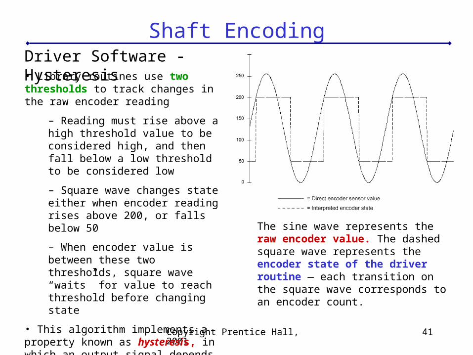
Shaft EncodingDriver Software - Hysteresis• Library routines use two thresholds to track changes in the raw encoder reading
– Reading must rise above a high threshold value to be considered high, and then fall below a low threshold to be considered low
– Square wave changes state either when encoder reading rises above 200, or falls below 50
– When encoder value is between these two thresholds, square wave “waits” for value to reach threshold before changing state
• This algorithm implements a property known as hysteresis, in which an output signal depends on the input signal and its recent history
The sine wave represents the raw encoder value. The dashed square wave represents the encoder state of the driver routine — each transition on the square wave corresponds to an encoder count.
Copyright Prentice Hall, 2001 42
Shaft EncodingMeasuring Velocity• Driver routines measure rotational velocity as well as position
– Subtract difference in the position readings after an interval of time has elapsed
• Velocity readings can be useful for a variety of purposes
– Robot that has an un-powered trailer wheel with a shaft encoder can easily tell whether it is moving or not by looking at encoder activity on the trailer wheel. If the robot is moving, the trailer wheel will be dragged along and will have a non-zero velocity. If the robot is stuck, whether or not its main drive wheels are turning, the trailer wheel will be still.
• Velocity information can be combined with position information to perform tasks like causing a robot to drive in the straight line, or rotate a certain number of degrees. These tasks are inherently unreliable because of mechanical factors like slippage of robot wheels on the floor and backlash in geartrains, but to a limited extent they can be performed with appropriate feedback from shaft encoders.
Copyright Prentice Hall, 2001 43
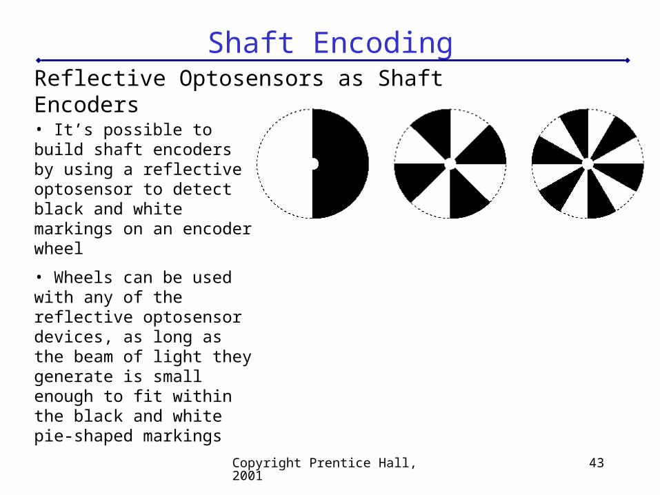
Shaft EncodingReflective Optosensors as Shaft Encoders
• It’s possible to build shaft encoders by using a reflective optosensor to detect black and white markings on an encoder wheel
• Wheels can be used with any of the reflective optosensor devices, as long as the beam of light they generate is small enough to fit within the black and white pie-shaped markings
Copyright Prentice Hall, 2001 44
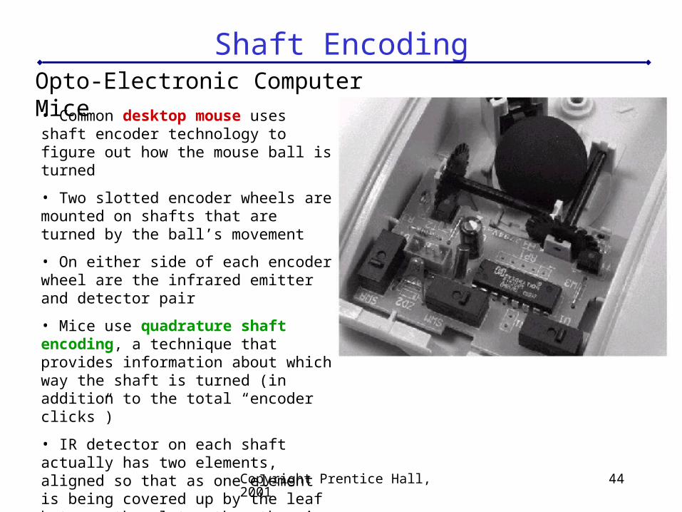
Shaft EncodingOpto-Electronic Computer Mice• Common desktop mouse uses shaft encoder technology to figure out how the mouse ball is turned
• Two slotted encoder wheels are mounted on shafts that are turned by the ball’s movement
• On either side of each encoder wheel are the infrared emitter and detector pair
• Mice use quadrature shaft encoding, a technique that provides information about which way the shaft is turned (in addition to the total “encoder clicks”)
• IR detector on each shaft actually has two elements, aligned so that as one element is being covered up by the leaf between the slots, the other is being exposed