Embed Size (px)
Citation preview
N A S A C O N T R A C T O R
R E P O R T
00CO
N A S A C R - 2 3 8 0
wo
SENSITIVITY ANALYSISOF TORSIONAL VIBRATIONCHARACTERISTICS OFHELICOPTER ROTOR BLADESPart II - Aerodynamics and Sensitivity Analysis
by Theodore Bratanow and Akin Ecer
Prepared by
UNIVERSITY OF WISCONSIN-MILWAUKEE
Milwaukee, Wis.
for Langley Research Center
NATIONAL AERONAUTICS AND SPACE ADMINISTRATION • WASHINGTON, D. C. • MARCH 1974
https://ntrs.nasa.gov/search.jsp?R=19740009498 2018-05-08T05:26:55+00:00Z
For sale by the National Technical Information Service, Springfield, Virginia 22151
1. Report No. 2. Government Accession No.
NASA CR-2380
4. Title and Subtitle
SENSITIVITY ANALYSIS OF TORSIONAL VIBRATION CHARACTER-ISTICS OF HELICOPTER ROTOR BLADES - PART II. AERODYNAMICSAND SENSITIVITY ANALYSIS7. Author(s)
THEODORE BRATANOW AND AKIN ECER
9. Performing Organization Name and Address
UNIVERSITY OF WISCONSIN - MILWAUKEEMILWAUKEE. WISCONSIN
12. Sponsoring Agency Name and Address
NATIONAL AERONAUTICS AND SPACE ADMINISTRATIONWASHINGTON, D.C. 20546
3. Recipient's Catalog No.
5. Report DateMARCH 1974
6. Performing Organization Code
8. Performing Organization Report No.
10. Work Unit No.
11. Contract or Grant No.
NGR 50-007-00113. Type of Report and Period Covered
CONTRACTOR REPORT
14. Sponsoring Agency Code
15. Supplementary Notes
TOPICAL REPORT
16. Abstract
A THEORETICAL INVESTIGATION OF DYNAMIC RESPONSE CHARACTERISTICS OF ROTOR BLADESWAS CARRIED OUT WITH SPECIAL EMPHASIS ON TORSIONAL DEGREES-OF-FREEDOM. COUPLEDEQUATIONS OF MOTION FOR FLAPWISE BENDING AND TORSION WERE FORMULATED AT VARYINGAZIMUTH POSITIONS FOR ROTOR BLADES WITH NONCOLLINEAR AERODYNAMIC, ELASTIC AND MASSAXES, BOTH STRUCTURAL AND AERODYNAMIC MASS, DAMPING AND STIFFNESS COEFFICIENTS WEREINCLUDED. THE VIBRATIONS OF A SAMPLE BLADE AT DIFFERENT FLIGHT CONDITIONS WEREINVESTIGATED FROM THESE EQUATIONS. THE OBTAINED NUMERICAL RESULTS WERE ILLUSTRATED.
THE SENSITIVITY OF OVERALL BLADE VIBRATION CHARACTERISTICS TO TORSIONALOSCILLATIONS WAS ALSO INVESTIGATED FROM THE EQUATIONS OF MOTION FOR THE SAMPLEBLADE. THE ILLUSTRATED RESULTS SHOW THE IMPORTANCE OF TORSIONAL DEGREES-OF-FREEDOMIN ROTOR.BLADE ANALYSIS. VARIOUS POSSIBILITIES OF IMPROVING THE OVERALL RESPONSE BYTUNING BLADE GEOMETRIC, STRUCTURAL AND AERODYNAMIC CHARACTERISTICS ARE DISCUSSED.
17. Key Words (Suggested by Author(s))
ROTOR BLADE DYANMICSAERODYNAMIC LOADSTORSIONAL OSCILLATIONSCOUPLED RESPONSE
18. Distribution Statement
UNCLASSIFIED - UNLIMITED
Cat.19. Security Oassif. (of this report)
UNCLASSIFIED20. Security Classif. (of this page)
UNCLASSIFIED21. No. of
62
22. Price
$3.50

Page Intentionally Left Blank
CONTENTS
, ' Page
SUMMARY . 1
INTRODUCTION . • . . 2
SYMBOLS ' . . . - . . 2
AERODYNAMICS OF ROTOR BLADES IN FORWARD FLIGHT 6
Background 6
Method of Solution 6
Analysis of the Aerodynamic Loading in Bending and Torsion 8
ANALYSIS OF THE COUPLED EQUATIONS OF MOTION OF A ROTOR BLADEIN FORWARD FLIGHT 9
Method of Solution 9
In the forward flow region 11
In the reverse flow region 11
Sensitivity Analysis of Torsional Vibration Characteristicsof a Sample Blade 12
Conclusions 14
APPENDIX - CALCULATION OF THE AERODYNAMIC LOADING IN FORWARDFLIGHT 16
Blade Flapping Motion . 16
Blade Torsional Motion 19
REFERENCES 22
TABLES . 24
FIGURES 27
111
TABLES
Table Page
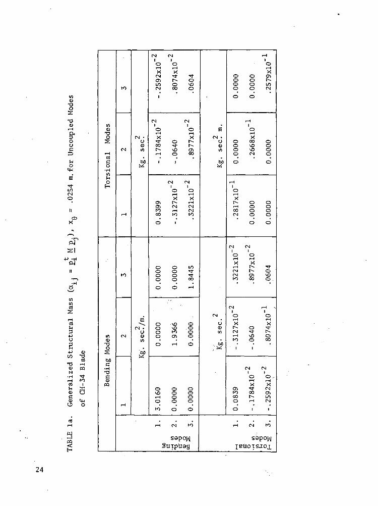
la Generalized Structural Mass (a.. = p. M p.)>*• ij i - jx. = 0.025 for Uncoupled Modes of the CH-34 Blade. 24y
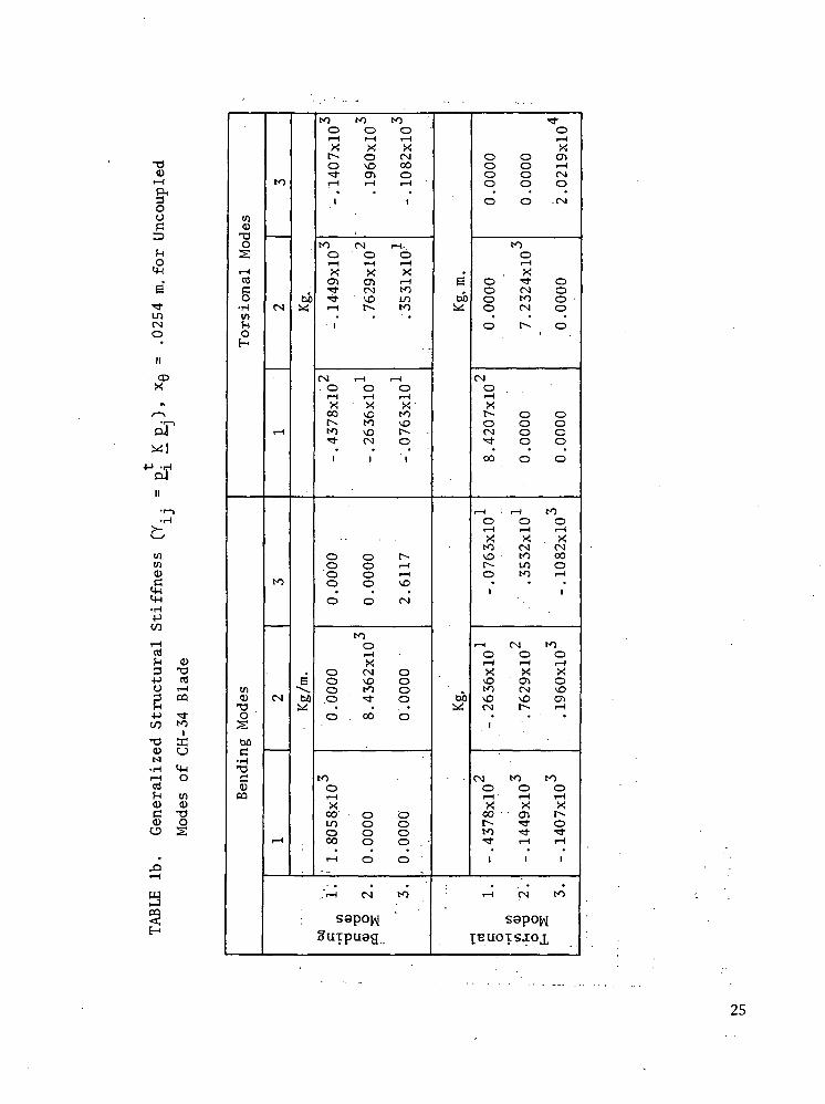
lb Generalized Structural Stiffness (Y.. = p. Kp.)>v' i j % — - -j xQ = 0.025 for Uncoupled Modes of the CH-34 Blade. 25
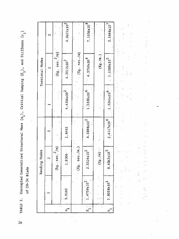
2 Uncoupled Generalized Structural Mass (a.)>
Critical Damping (3..), and Stiffness (Y-.)»
of the CH-34 Blade. 26
IV
ILLUSTRATIONS
Figure Page
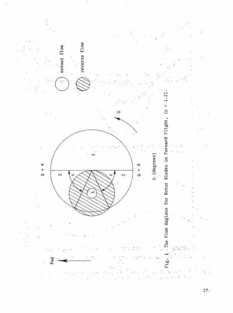
1 The Flow Regions for Rotor Blades in Forward Flight,(v = 1.2). 27
2 Variation of Aerodynamic Bending Stiffness with BladeAzimuth Positions, (u = 0.22, K = 0.5, XQ = 0.0). 28
3 Variation of Aerodynamic Bending Damping with BladeAzimuth Positions, (U = 0.22, K = 0.5, XQ = 0.0). 28
4 Variation of Aerodynamic Bending Coupling with BladeAzimuth Positions, (u = 0.22, K = 0.5, XQ = 0.0). 29
5 Aerodynamic Stiffness in First Bending Mode at VariousAdvance Ratios, (K = 0.5, XQ = 0.0). 29
6 Aerodynamic Damping in First Bending Mode at VariousAdvance Ratios, (K = 0.5, XQ = 0.0). 30
7 Aerodynamic Stiffness Coupling of First Torsional andFirst Bending Modes at Various Advance Ratios,(K = 0.5, XQ = 0.0). . 30
8 Aerodynamic Stiffness for First Torsional Mode withVarious Advance Ratios, (K = 0.5, XQ = 0.0). 31
9 Aerodynamic Damping for First Torsional Mode withVarious Advance Ratios, (K = 0.5, xfl = 0.0). 31
10 Aerodynamic Stiffness of First Bending and FirstTorsional Modes at Various Advance Ratios,(K = 0.5, XQ = 0.0). 32
11 Aerodynamic Damping Coupling of First Bending andFirst Torsional Modes at Various Advance Ratios,(K = 0.5, XQ = 0.0). 32
12 Variation of Natural Bending Frequency and DampingRatio with Blade Azimuth Positions, (M = 0.22,K = 0.5, XQ = 0.0). 33
13 Variation of Natural Torsional Frequency and DampingRatio with Blade Azimuth Positions, (y = 0.22,K = 0.5, XQ = 0.0). 34
14 Variation of Coupling: Ratios for the Torsional andBending Modes with Blade Azimuth Positions, (y = 0.22,K = 0.5, XQ = 0.0). ' 35
15 Variation of Natural Bending and Torsional Frequencieswith Blade Azimuth Positions for Various Eccentricitiesbetween Elastic and Mass Axes, (y =,0.22, K = 0.5). " 36
16 Variation of Coupling Ratios for the Bending Mode withBlade Azimuth Positions for Various Eccentricities
. between Elastic and Mass Axes, CU = 0.22, K = 0.5). 37
17 Variation of Coupling Ratios for the Torsional Modewith Blade Azimuth Positions for Various Eccentricitiesbetween Elastic and Mass Axes, (u = 0.22, K = 0.5). 38
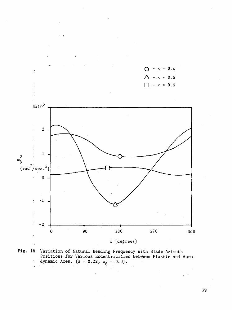
18 Variation of Natural Bending Frequency with BladeAzimuth Positions for Various Eccentricities betweenElastic and Aerodynamic Axes, (y = 0.22, xfl = 0.0). 39
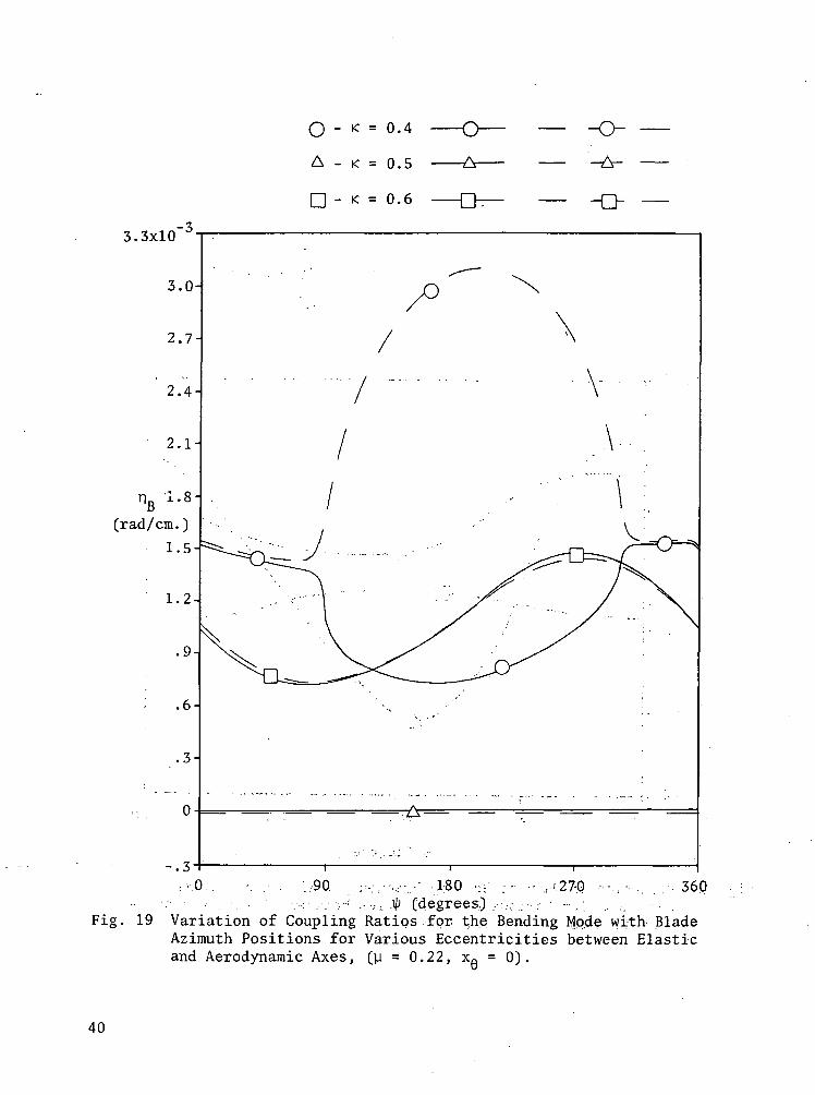
19 Variation of Coupling Ratios for the Bending Modewith Blade Azimuth Positions for Various Eccentricitiesbetween Elastic and Aerodynamic Axes, (u = 0.22,X0 = 0.0). 40o
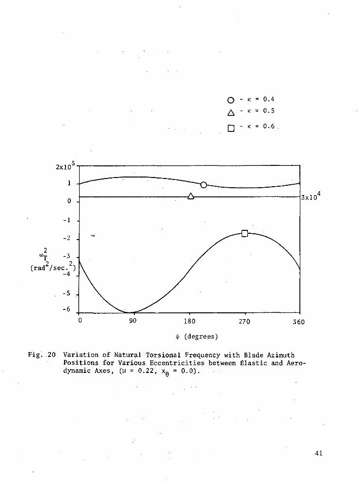
20 Variation of Natural Torsional Frequency with BladeAzimuth Positions for Various Eccentricities betweenElastic and Aerodynamic Axes, (u = 0.22, xfi = 0.0). 41
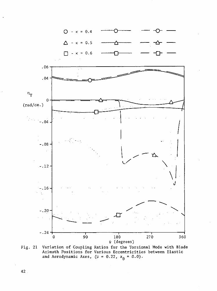
21 Variation of Coupling Ratios for the Torsional Modewith Blade Azimuth Positions for Various Eccentricitiesbetween Elastic and Aerodynamic Axes, (y = 0.22, xfl = 0.0). 42
22 Variation of Natural Bending Frequency with Blade.Azimuth Positions for Various Tip-Speed Ratios,CK = 0.5, XQ = 0.0). 43w
23 Variation of Coupling Ratios for the Bending 'Mode withBlade Azimuth Positions for Various Tip-Speed Ratios,CK = 0.5, XQ = 0.0). 44
u
24 Variation of Natural Bending Frequency with Blade .Azimuth Positions for Various Tip-Speed Ratios, ^CK = 0.4, xa = 0.0). 45w
25 Variation of Coupling Ratios for the Bending Mode withBlade Azimuth Positions for Various Tip-Speed Ratios,CK = 0.4, XQ = 0.0). 46
u
26 Variation of Natural Bending Frequency with BladeAzimuth Positions for Various Tip-Speed Ratios,CK = 0.6, XQ = 0.0). . 47u
27 Variation of Coupling Ratios for the Bending Mode withBlade Azimuth Positions for Various Tip-Speed Ratios,CK = 0.6, XQ = 0.0). 48
28 Variation of Natural Torsional Frequency with BladeAzimuth Positions for Various Tip-Speed Ratios,CK = 0.5, XQ = 0.0). 49
D
vi
29 Variation of Coupling Ratios for Torsional Mode withBlade Azimuth Positions for Various Tip-Speed Ratios,(K = 0.5, XQ = 0.0). "50
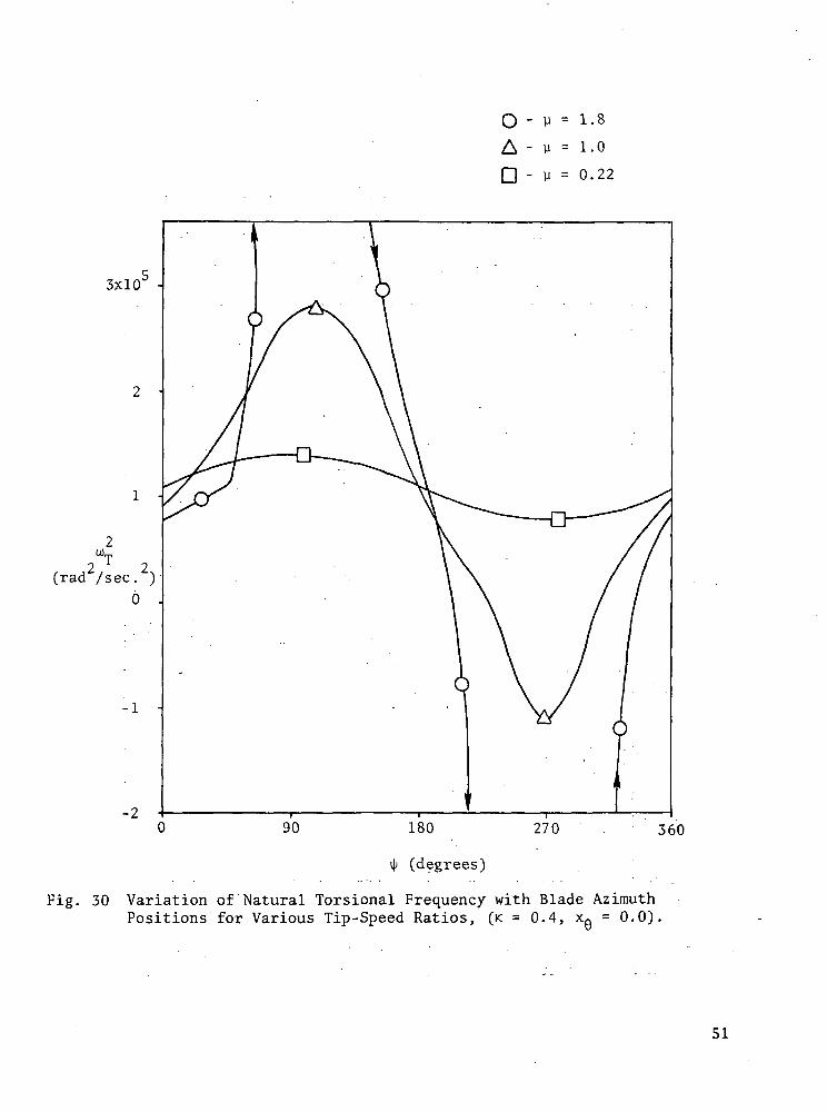
30 Variation of Natural Torsional Frequency with BladeAzimuth Positions for Various Tip-Speed Ratios,(K = 0.4, XQ = 0.0). 51
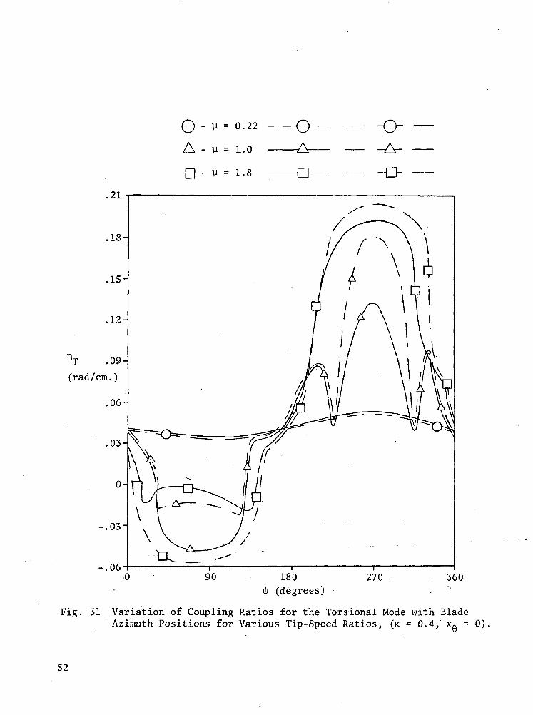
31 Variation of Coupling Ratios for the Torsional Modewith Blade Azimuth Positions for Various Tip-SpeedRatios, (K = 0.4, XQ = 0.0). 52t)
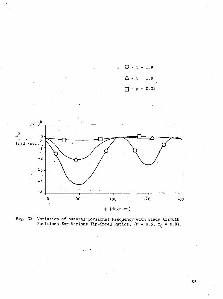
32 Variation of Natural Torsional Frequency with BladeAzimuth Positions for Various Tip-Speed Ratios,(K = 0.6, XQ = 0.0). 53
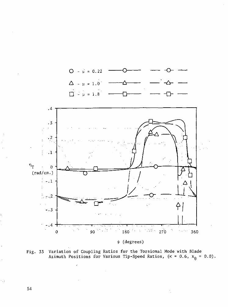
33 Variation of Coupling Ratios for the Torsional Modewith Blade Azimuth Positions for Various Tip-SpeedRatios, (K = 0.6, XQ = 0.0). 54
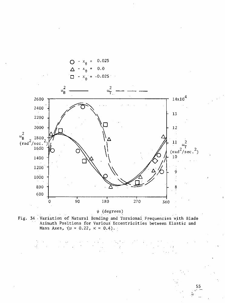
34 Variation of Natural Bending and Torsional Frequencieswith Blade Azimuth Positions for Various Eccentricitiesbetween Elastic and Mass Axes, (y = 0.22, K = 0.4). 55
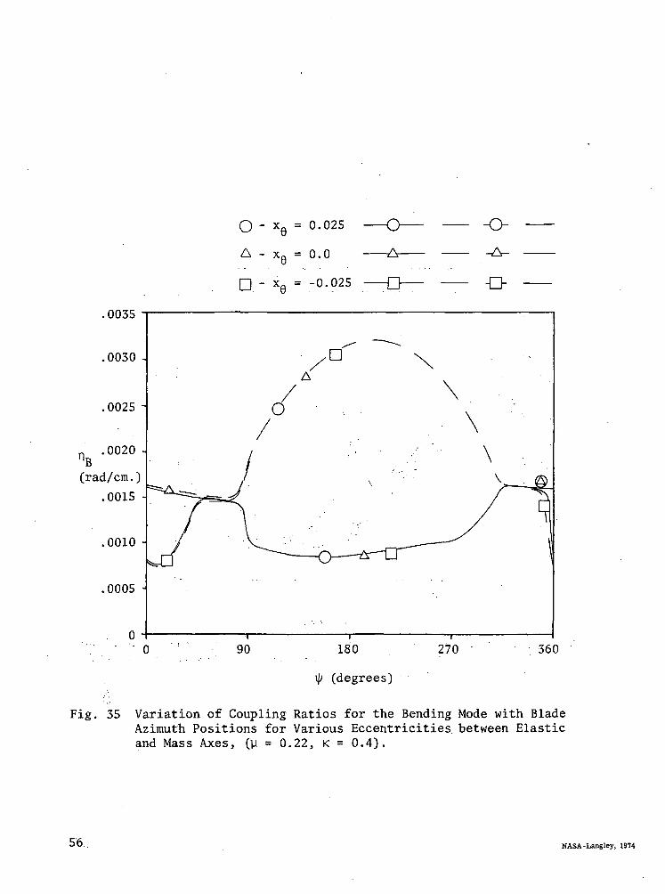
35 Variation of Coupling Ratios for the Bending Mode withBlade Azimuth Positions for Various Eccentricitiesbetween Elastic and Mass Axes, (ji = 0.22, K = 0.4). 56
VII
SENSITIVITY ANALYSIS OF TORSIONAL VIBRATIONCHARACTERISTICS OF HELICOPTER ROTOR BLADES
Part II. AERODYNAMICS AND SENSITIVITY ANALYSIS
By Theodore Bratanow* and Akin Ecer**University of Wisconsin-Milwaukee
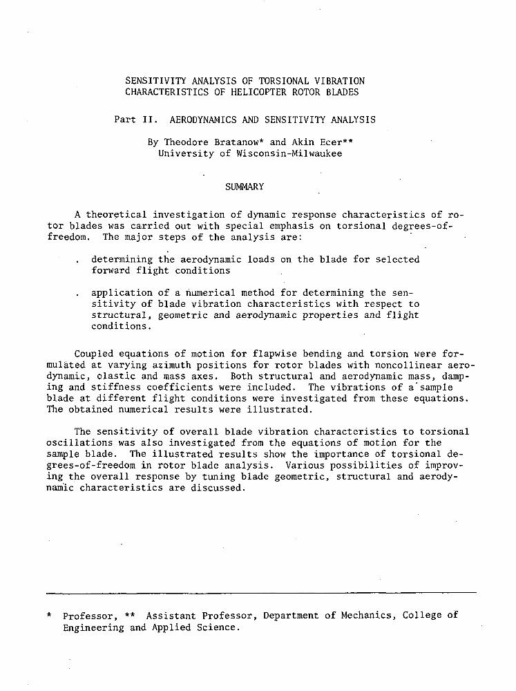
SUMMARY
A theoretical investigation of dynamic response characteristics of ro-tor blades was carried out with special emphasis on torsional degrees-of-freedom. The major steps of the analysis are:
determining the aerodynamic loads on the blade for selectedforward flight conditions
application of a numerical method for determining the sen-sitivity of blade vibration characteristics with respect tostructural, geometric and aerodynamic properties and flightconditions.
Coupled equations of motion for flapwise bending and torsion were for-mulated at varying azimuth positions for rotor blades with noncollinear aero-dynamic, clastic and mass axes. Both structural and aerodynamic mass, damp-ing and stiffness coefficients were included. The vibrations of a"sampleblade at different flight conditions were investigated from these equations.The obtained numerical results were illustrated.
The sensitivity of overall blade vibration characteristics to torsionaloscillations was also investigated from the equations of motion for thesample blade. The illustrated results show the importance of torsional de-grees-of-freedom in rotor blade analysis. Various possibilities of improv-ing the overall response by tuning blade geometric, structural and aerody-namic characteristics are discussed.
Professor, ** Assistant Professor, Department of Mechanics, College ofEngineering and Applied Science.
INTRODUCTION
The objectives of the conducted investigation were to determine the var-iation of torsional oscillations and their effect in forward flight on bladedynamic response characteristics and to analyze the sensitivity of torsionaloscillations to blade aerodynamic, structural and geometric properties. Inthe first report [1], the structural aspects of the analysis were presented.In this report the aerodynamic characteristics of rotor blades are definedfor varying forward flight conditions. The unsteady effects due to thepitching motion of the blade were determined from two-dimensional airfoiltheory [2]. The aerodynamic loading in each of the structural vibrationmodes was determined for different flight conditions and then the aerodynamicstiffness and damping coefficients were calculated. These coefficients werecompared with structural stiffness and damping coefficients for varying azi-muth positions. Then the structural and aerodynamic coefficients were com-bined for a complete, coupled vibration analysis in forward flight. The sen-sitivity of the torsional vibrations in forward flight to structural and geo-metric properties of the sample blade'was investigated. The effects of thevariations of mass, elastic and aerodynamic axes of the sample blade were il-lustrated for various flight conditions.
SYMBOLS
a lift curve slope for forward flow
a' lift curve slope for reverse flow ' • '•
a.; generalized aerodynamic mass coefficient
b. : -generalized aerodynamic damping coefficient
B tip loss factor
c blade chord-width, m.
c.: generalized aerodynamic'stiffness coefficient ;
CT lift coefficient ' 'L
Cn- generalized control moment stiffness in torsion
D; damping matrix
f. (jt) generalized external load function in each mode, N
£(t) generalized external load function, N
F- WO generalized force in bending, N
G-OJO generalized control moment in torsion, N-ih•'"•'• - • • •
h vertical displacement of the blade at the elastic center, m.
h. eigenfunction corresponding to-the bending displacement componentof p_. , m.
K stiffness matrix
L lift generated by a blade, N
Ln lift generated by a blade in reverse flow, N- K . . -.- : ' ; • . * . • • ; . • - • ;•....•. . : ' , . ,:
L . 010 forcing function component for lift, N
2m., generalized coupled torsional stiffness in bending, N-m
M . OJj) forcing function component for moment, N-m
Mp a feathering moment, N-m
M mass matrix '"' ' " •• ' ' ' ;; '"
p_. eigenvector of the- structural system ; '• • •:
p.. generalized torsional "damping1 in torsion, N-s'ec./rad •
P. . generalized bending damping in bending, N-sec./m
q. . generalized torsional stiffness in torsion, • N/rad
Q. . generalized bending stiffness in bending, N/m
r distance of rotor blade element from center of rotation, m.
r_ coupled displacement vector, m.
R rotor radius, m.
R, . generalized coupled bending stiffness in torsion, N/mK.X - . . , .
S, . generalized coupled bending damping in torsion, N-sec./radK l :.'. ' . : . : " ' ' ' . . . . . - • • • - - • • '
t time
U normal component of the resultant velocity at a -blade element, m/sec.
U tangential component of the resultant velocity at a blade element, :-m/sec.
v. induced velocity, m/sec.
V forward velocity, m/sec.
XQ eccentricity between the elastic and mass center, m.o
X. generalized bending deflection at blade tip, m.
Y. generalized torsional rotation at blade tip, rad
Z. generalized displacement in a coupled mode, m.
a. generalized structural mass coefficient
a blade element angle of attack, rad
3 blade flapping angle at particular azimuth position, rad
3- eigenfunction corresponding to the bending rotation component of p.,1 rad x
3. generalized structural damping coefficient, N-sec./m
y. generalized structural stiffness coefficient, N/m
e an angle defining reverse flow region, rad .
0 pitch change due to blade torsion, rad
6 lateral cyclic pitch control input, radc
9. eigenfunctions corresponding to the.torsional rotation component ofp_., rad
0 collective pitch, rad
0 longitudinal cyclic pitch control input, rad
0 pitch angle of a blade element without considering torsion, rad
0 built-in blade twist, rad
KC distance between elastic axis and center of pressure in reversed flowregion, m.
X - inflow ratio (see Eq. (A6))
y tip-speed ratio
D ratio of torsional rotations to bending displacements in the vibrationmode corresponding to the lowest frequency, rad/m
p mass density of air, kg/m
ip azimuth angle, rad
to coupled frequency of the blade, rad/sec.
fl angular velocity of a rotating blade, rad/sec.
Subscripts
A aerodynamic
s structural
Superscripts
B bending
t transpose
T torsion
AERODYNAMICS OF ROTOR BLADES IN FORWARD FLIGHT
Background
The effects of torsional oscillations of blades become an important con-sideration in predicting dynamic response characteristics of high performancerotorcraft. Torsional oscillations of rotor blades have been considered byresearchers in connection with stability and stall problems. The stabilityof coupled bending and torsional vibratory motion of rotor blades at highforward speeds has been treated by several investigators [3,4,5]. The tor-sional loads used in such analyses have been calculated at lower tip-speedratios, when the coupled torsional rotations are relatively small. Underthese conditions and when the blade has a sufficiently high torsional stiff-ness compared to the bending stiffness, the torsional motion has a minor ef-fect on blade stability. Large torsional rotations change the aerodynamiccharacteristics considerably and affect the stability of the rotor blade.
The stall characteristics of rotor blades have also been studied [6,7,8]. Ham [7,8] for instance, has shown that for stall conditions the aero-dynamic damping of torsional oscillations becomes negative as the pitchangle increases. To balance such a negative aerodynamic damping, he sug-gested measures for addition of a positive mechanical damping. '
Various investigators have been involved in determining bending andtorsional aerodynamic loads on vibrating blades in forward flight [9,10]. Acomplete investigation of the response of rotor blades at high forward speedsrequires a three-dimensional aeroelastic representation of the problem. Theaerodynamics of a three-dimensional flow around the rotor blade at high for-ward speeds is not sufficiently developed for an accurate determination ofcoupled aerodynamic loads.
In the conducted investigation, effects of torsional oscillations wereevaluated by quantitative comparisons of a series of structural and aero-dynamic parameters. The aerodynamic loading in forward flight was deter-mined according to the classical rotor blade analysis [3,4,11,12,13] as de-scribed in the Appendix. ~~~
Method of Solution
The equations of motion of a rotor blade can be expressed in a generalmatrix form as follows:
M r + D_ r + K_ r = F_ (t) (1)
where the mass, damping, and stiffness matrices can be considered as con-sisting of two components, structural and aerodynamic.
M = MS + V^ (2)
K s Kg t 40W (3)
D = + D O J O (4)
The aerodynamic terms in Eqs. (2), (3) and (4) are functions of blade azimuth position and flight conditions. Considering only the structural components of the matrices in Eqs. (2), (3), and (4) and generating a struc-tural damping matrix proportional to the critical damping, one can obtainthe eigenvectors for the following system:
2-co M p. + Kp. = 0 where r = Z.p. (5)— s*-i -5% — i*-! . : }
so that the generalized structural mass, stiffness, and damping terms canbe calculated as .
a. = EJ ^ p_. (6)
and
p* M p . = pt D p .' = p^ K p . = 0 f o r i / j , (9)*-l — S *-J *-l — S *-J *-l — S *-J '
The generalized aerodynamic mass, damping, and stiffness terms are definedas
a.-W = E^M^Ej (10)
b.. W = 4 DA p_. (11)
= £ E (12).
Then one can write the generalized equations of motion as
ou + a.. CIO" | X. + | B- + b . . O I O I X. * I Yi + c. .C« j X. - f.( t)
(13)
In Eq. (13), the aerodynamic terms are coupled in each mode. The responseproblem can be analyzed from the solution of the system of second order dif-ferential equations with periodic coefficients in Eq. (13). These coeffi-cients consist of a constant uncoupled term and a periodic coupled term.
The aerodynamic coefficients in Eq. (13) were determined for the flowregions shown in figure 1 in terms of the coupled vibration modes as de-scribed in the Appendix. These coefficients were calculated for typicalflight conditions.
Analysis of the Aerodynamic Loading in Bending and Torsion
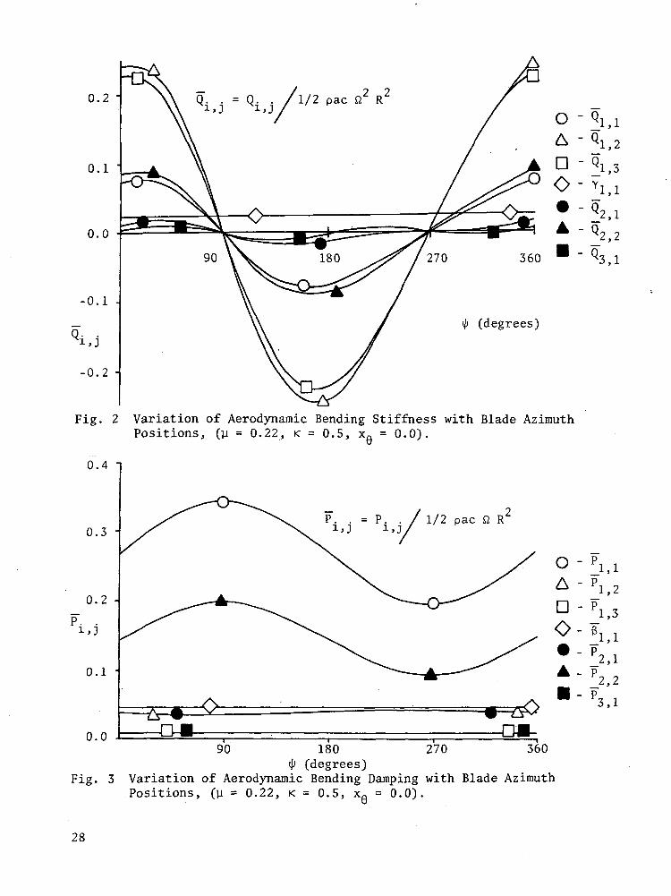
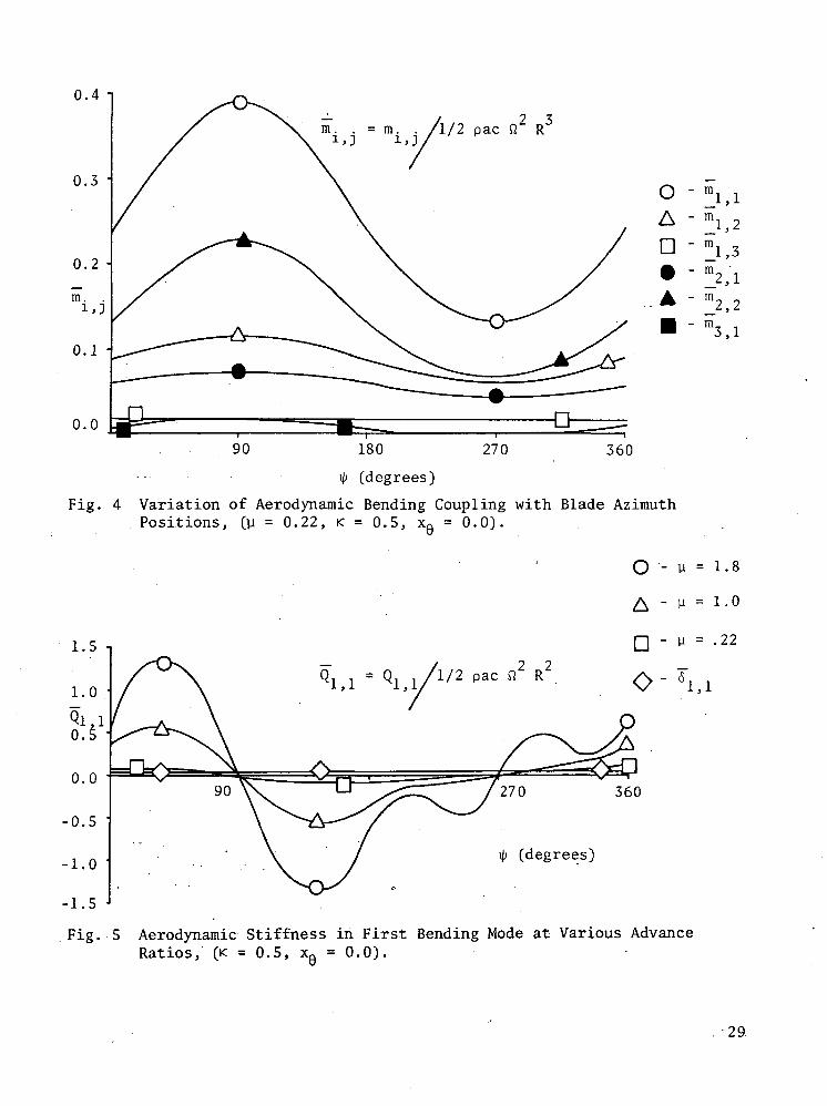
A sample blade (CH-34) was chosen to demonstrate the variation of theaerodynamic coefficients for different modes. The structural generalizedmass and stiffness terms for each mode and coupling between modes were cal-culated as shown in table 1. The structural coupling between the lowestthree modes is summarized in table 2. To illustrate the aerodynamic cou-pling between each of these modes, the aerodynamic stiffness and dampingcoefficients for the different modes were calculated as shown in figures 2,3, and 4. From the curves one may observe the degree of coupling betweenthe aerodynamic forces in each mode.
Each of the terms defined in Eqs. (A19), (A20), and (A21), was plottedfor various tip-speed ratios for the mode corresponding to the lowest bend-ing frequency. The aerodynamic bending stiffness, Q1 , represents the re-
sultant force in the first structural mode due to unit displacement in thesame mode and is plotted in figure 5. For a tip-speed ratio correspondingto the indicated operational speed of a CH-34 blade (y = 0.22), the aero-dynamic bending stiffness of the blade is in the range of the calculatedstructural stiffness. For this case the effect of the reverse flow regionis negligible. In general, as the tip-speed ratio increases, the bendingstiffness values show a greater variation with changes in azimuth positions;this variation of the stiffness is greater in the forward flow region andsmaller in the reverse flow region. Therefore, for high tip-speed ratios ofthe blade, stability problems may arise in the flapping mode due to the re-sulting negative bending stiffness.
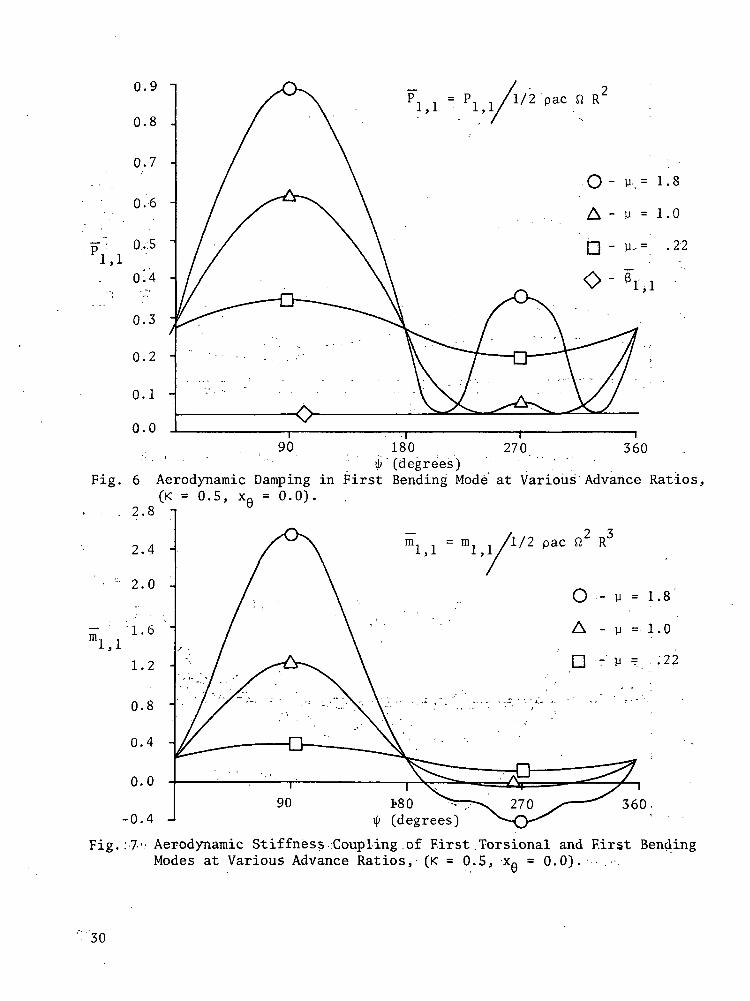
As shown in figure 6, the generalized aerodynamic damping in the firstbending mode, PI1, also depends on the tip-speed ratio of the blade. For
the operating speed of the CH-34 blade, the aerodynamic damping coefficientP.... is found to have nearly a constant value; however, it varies consid-
erably when the tip-speed ratio is increased. The aerodynamic damping in-creases in the forward flow region but it nearly vanishes for the reverseflow region. The decrease in the aerodynamic damping may be one of thereasons for the existence of increased bending amplitudes in the reverseflow region. It should be noted also that the calculated values of aero-dynamic damping are found to be considerably high compared to the struc-tural damping of the CH-34 blade. Such results suggest that a further
examination of values of characteristic aerodynamic damping for rotor bladesat high forward speeds is desirable.
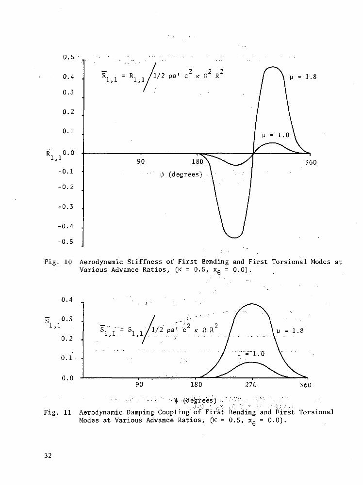
The aerodynamic stiffness term from the coupling of the first bendingand torsional modes was also found to be dependent on the forward speed. Asshown in figure 7, this stiffness term has a different sign for differentflow regions at high tip-speed ratios, but it is nearly constant for low tip-speed ratios.
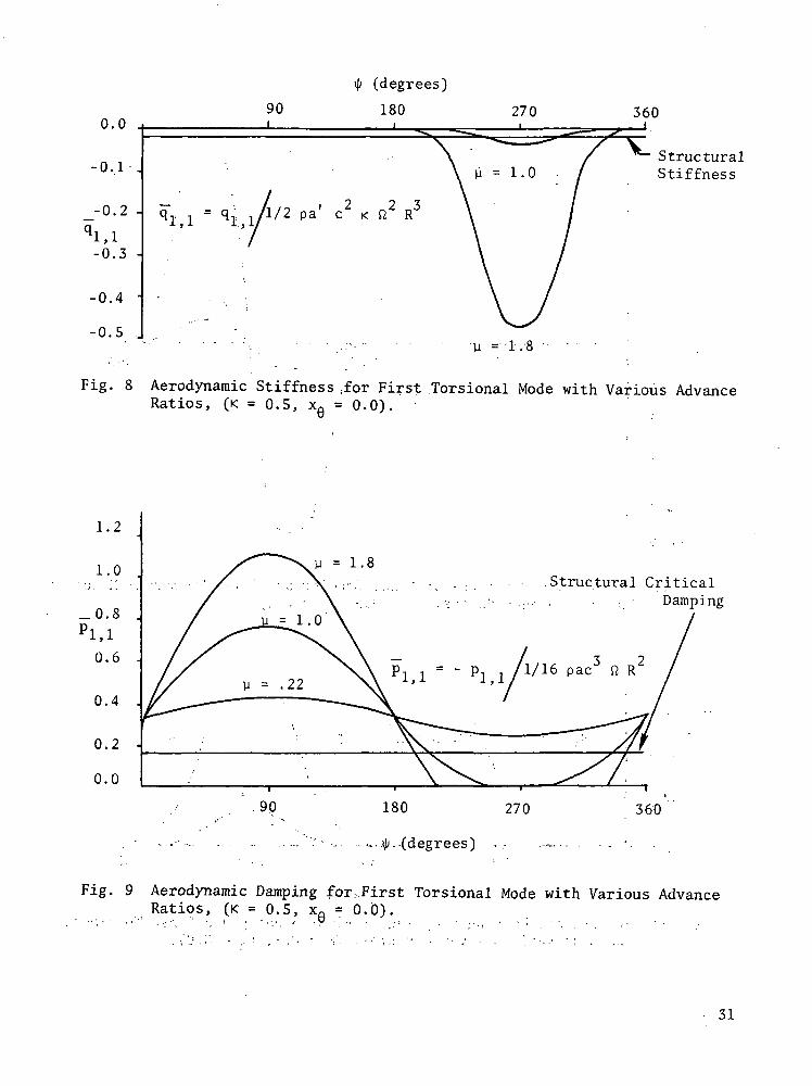
The variation of torsional stiffness and damping parameters with azi-muth positions and tip-speed ratios is shown in figures 8, 9, 10, and 11.Aerodynamic torsional stiffness in the first mode exists only in the reverseflow region. As can be seen from figure 8, this stiffness acts as a neg-ative feathering spring for the reverse flow region and its magnitude is pro-portional to the increase in tip-speed ratios. Accordingly, the total tor-sional stiffness of the blade has lower values in the reverse flow region.The structural torsional stiffness of the blade must be increased in orderto overcome this negative aerodynamic stiffness.
The variation of the torsional damping for various tip-speed ratioswas also investigated and is shown in figure 9. For high tip-speed ratios,torsional damping becomes higher for the forward flow region, while for thereverse flow region the aerodynamic torsional damping vanishes. The vari-ations of the coupled aerodynamic stiffness and damping terms are shown infigures 10 and 11. These coupled terms also exist only for the reverseflow region and increase proportionally to the tip-speed ratios.
ANALYSIS OF THE COUPLED EQUATIONS OF MOTIONOF A ROTOR BLADE IN FORWARD FLIGHT
Method of Solution
The coupled equations of motion of rotor blades in bending and torsioncan be expressed in terms of the generalized mass, damping and stiffnesscoefficients. These equations are:
a? X. + |8?11 |_ i + P.-OIO X. . + Y? + Q.-OIO X. . + Y, m., 010 = L . (<JO^rj ' x ^rj h vr' vr'
(14)
for the bending motion, and
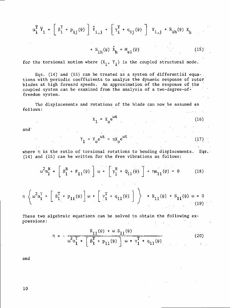
for the torsional motion where (X., Y.) is the coupled structural mode.
Eqs. (14) and (15) can be treated as a system of differential equa-.tions with periodic coefficients to analyze the dynamic response of rotorblades at high forward speeds. An approximation of the response of thecoupled system can be examined from the analysis of a two-degree-of-freedom system.
The displacements and rotations of the blade can now be assumed asfollows:
and
XL = X ewt . (16)
Y = YoeWt= nX/* ' ; (17)
where n is the ratio of torsional rotations to bending displacements. Eqs.(14) and (15) can be written for the free vibrations as follows:
0® + PUW 0) + y + Q(W + nm(^) = 0 (18)
u = 0
(19)
These two algebraic equations can be solved to obtain the following ex-pressions: . . -
dj +
R (ip) + CO S (if;)- - - (20)
and
10
P,, OJO u + Y + Qn OJO ) < U« + B + Pll OJO I 0)
Yl
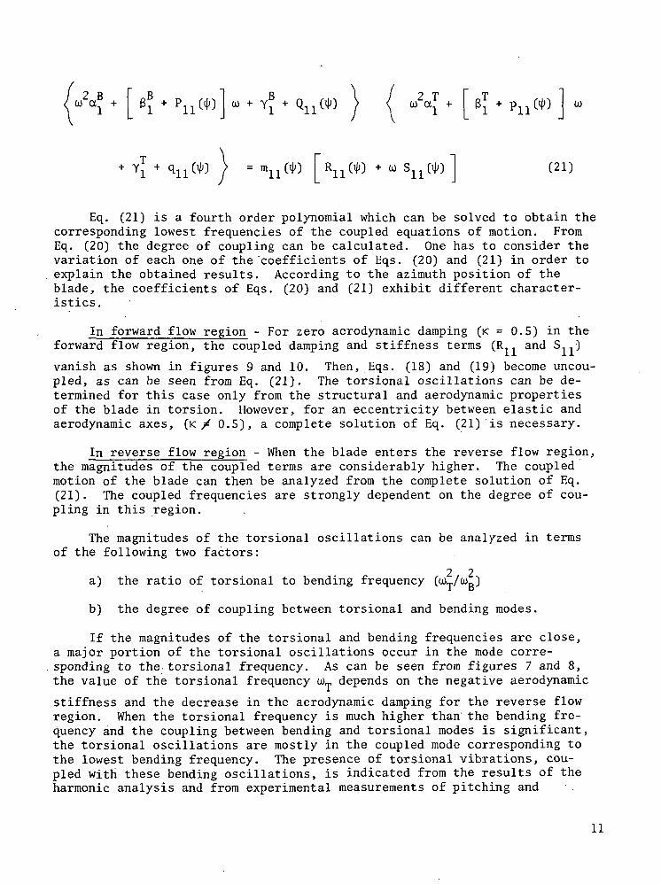
Eq. (21) is a fourth order polynomial which can be solved to obtain thecorresponding lowest frequencies of the coupled equations of motion. FromEq. (20) the degree of coupling can be calculated. One has to consider thevariation of each one of the 'coefficients of Eqs. (20) and (21) in order toexplain the obtained results. According to the azimuth position of theblade, the coefficients of Eqs. (20) and (21) exhibit different character-istics.
In forward flow region - For zero aerodynamic damping (K = 0.5) in theforward flow region, the coupled damping and stiffness terms (R. , and S ....•)
vanish as shown in figures 9 and 10. Then, Eqs. (18) and (19) become uncou-pled, as can be seen from Eq. (21). The torsional oscillations can be de-termined for this case only from the structural and aerodynamic propertiesof the blade in torsion. However, for an eccentricity between elastic andaerodynamic axes, (K / 0.5), a complete solution of Eq. (21) is necessary.
In reverse flow region - When the blade enters the reverse flow region,the magnitudes of the coupled terms are considerably higher. The coupledmotion of the blade can then be analyzed from the complete solution of Eq.(21) . The coupled frequencies are strongly dependent on the degree of cou-pling in this region.
The magnitudes of the torsional oscillations can be analyzed in termsof the following two factors:
2 2a) the ratio of torsional to bending frequency (u)T/u>B)
b) the degree of coupling between torsional and bending modes.
If the magnitudes of the torsional and bending frequencies are close,a major portion of the torsional oscillations occur in the mode corre-sponding to the. torsional frequency. As can be seen from figures 7 and 8,the value of the torsional frequency WT depends on the negative aerodynamic
stiffness and the decrease in the aerodynamic damping for the reverse flowregion. When the torsional frequency is much higher than the bending fre-quency and the coupling between bending and torsional modes is significant,the torsional oscillations are mostly in the coupled mode corresponding tothe lowest bending frequency. The presence of torsional vibrations, cou-pled with these bending oscillations, is indicated from the results of theharmonic analysis and from experimental measurements of pitching and
11
plunging motion of rotor blades [8].
Sensitivity Analysis of Torsional Vibration Characteristicsof a Sample Blade
The sensitivity analysis of coupled torsional and bending vibrations wascarried out for a sample blade (CH-34) as described above. Quantitative re-sults were obtained from the solution of Eqs. (20) and (21) for differentflight conditions and varying the blade properties.
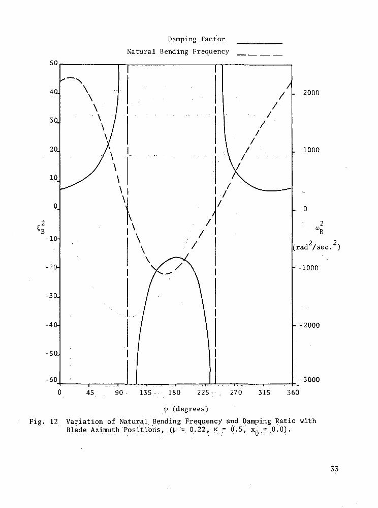
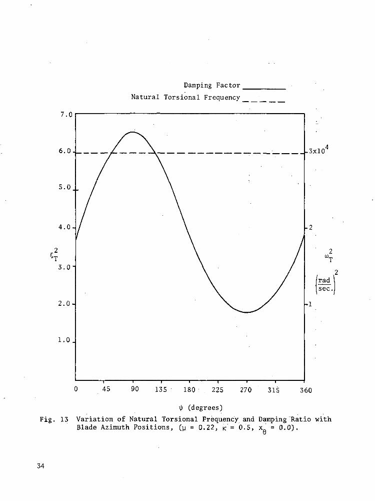
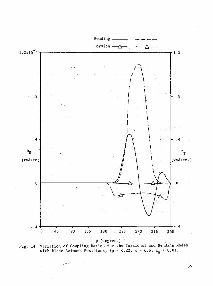
Figures 12-14 show the response of the blade in forward flight for coin-ciding elastic and aerodynamic axes. For the operational speed of thesample blade (U = 0.22), the aerodynamic damping and the natural bendingfrequency show a periodic variation, corresponding to the variation of bend-ing stiffness and damping coefficients in figures 2 and 3. As shown in fig-ure 9, torsional damping varies also periodically with changing azimuth po-sitions. However, the constant torsional structural stiffness is the im-portant factor in determining torsional frequency, as can be seen from fig-ure 8. The coupling ratio between torsional and bending modes (TJ) existsonly in the reverse flow region and reaches a maximum at an azimuth positionof 270°.
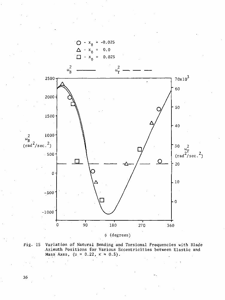
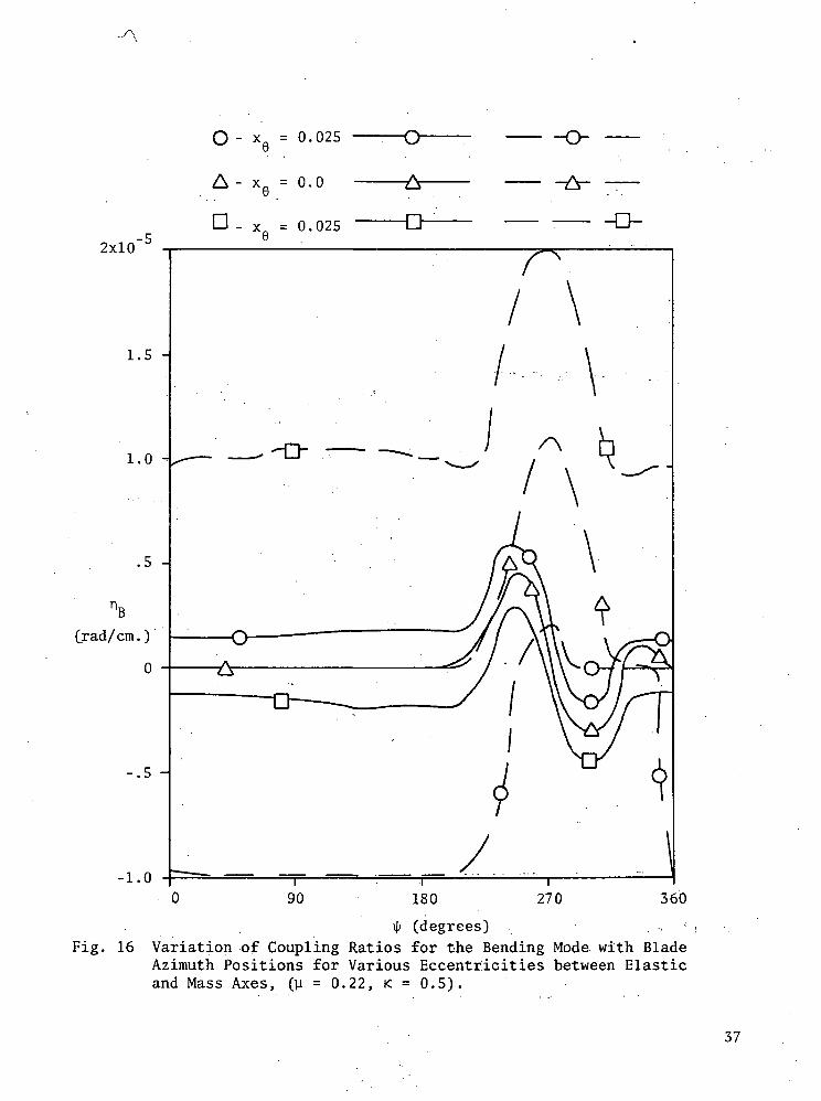
A detailed torsional sensitivity analysis of the rotor blade was furtherdeveloped starting from the ideal uncoupled case. The first term to be in-cluded in the sensitivity analysis was the effect of the eccentricity be-tween elastic and mass axes. The effects of structural coupling on bladeresponse, considering only the structural terms, were discussed in the firstreport [1]. The analysis can be extended to include the additional aerody-namic uncoupled loading of the blade. As shown in figures 15-17, in thiscase, bending and torsional frequencies were insensitive to the addition ofstructural eccentricity of the blade. Such behavior can be explained interms of the relative magnitudes of structural and aerodynamic coefficients.As described in the first report, bending frequencies are not sensitive tothe structural eccentricity (XQ) even without considering the aerodynamic
loading. The importance of this effect is indicated in the variation ofcoupling ratio with varying eccentricities. The coupling in the bendingmode is increased uniformly for all positions of the blade for an eccentric-ity of XQ = -1, and it exists mostly in the forward region for xfi = 1. The
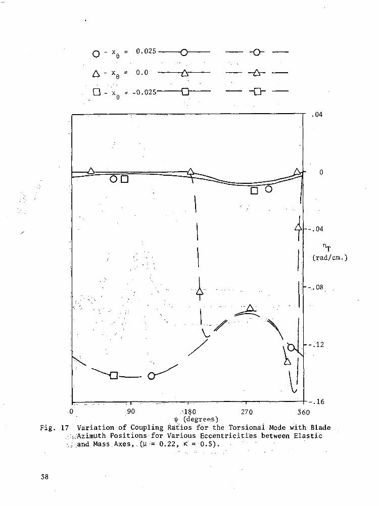
coupling ratio for the torsional mode is increased with additional eccen-tricity. The torsional frequencies are also increased as shown in figure 15.
The second term considered in the torsional sensitivity analysis of theblade was the effect of the relative position of aerodynamic axis with re-spect to the elastic axis. The exact position of the aerodynamic axis var-ies with time as the azimuth position of the blade changes in forward flight.The results obtained from the sensitivity analysis can be used in this caseto evaluate the effects of the changes in the aerodynamic and elastic axes,both qualitatively and quantitatively. The previous.results were obtained
12
for an ideal case, when the blade oscillates around the one-quarter chord-width and the distance between the elastic and aerodynamic axes is one-halfchord-width for both reverse and forward flows (K = 0.5). To investigatethe effect of the changes in the relative positions of the aerodynamic andelastic axes, the aerodynamic axis was moved in a symmetric fashion for for-ward and reverse flow by changing K to 0.4 and 0.6 respectively. The addi-tional aerodynamic pitching moments were included in the expressions in theAppendix for varying positions of elastic and aerodynamic axes. The ob-tained results were illustrated in figures 18-21.
Two cases (K = 0.6, K = 0.4) describe the behavior when the aerodynamicaxis is fore and aft of the elastic axis. The bending frequencies of therotor blade are reduced considerably for the entire rotor disc when K = 0.6.However, for K = 0.4 these frequencies show a consistent variation for dif-ferent azimuth positions. Compared to the case K = 0.5, the response ofthe blade is stabilized for azimuth positions 90° < ip < 270° for K = 0.4.This improvement is due to the additional stiffness obtained from the cou-pling with the torsional mode. On the other hand, the coupling ratio hasbeen increased considerably compared to the uncoupled case (K = 0.5). ForK = 0.4, the blade also exhibits an underdamped behavior for azimuth posi-tions 90° < ijJ < 360°.
The variation of torsional frequencies with coupling between mass andelastic axes is also an important consideration in the response analysis.While torsional frequencies are increased for K = 0.4, the blade is un-stable in a basically torsional mode f or K = 0.6. These results indi-cate that the blade vibrations may become unstable in a predominantly tor-sional mode, when the aerodynamic axis moves ahead of the elastic axis.The torsional vibrations are overdamped for K = 0.4.
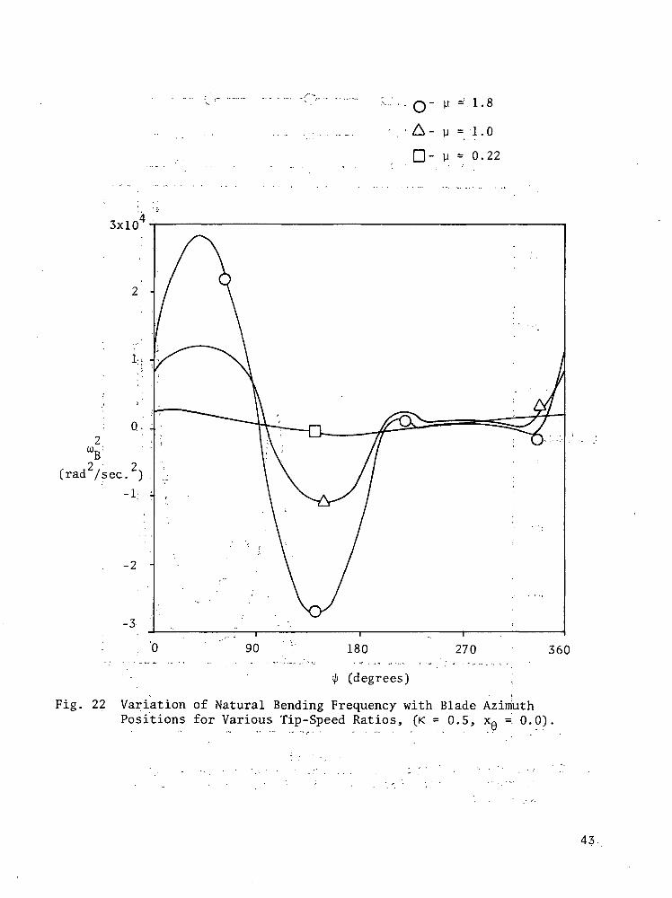
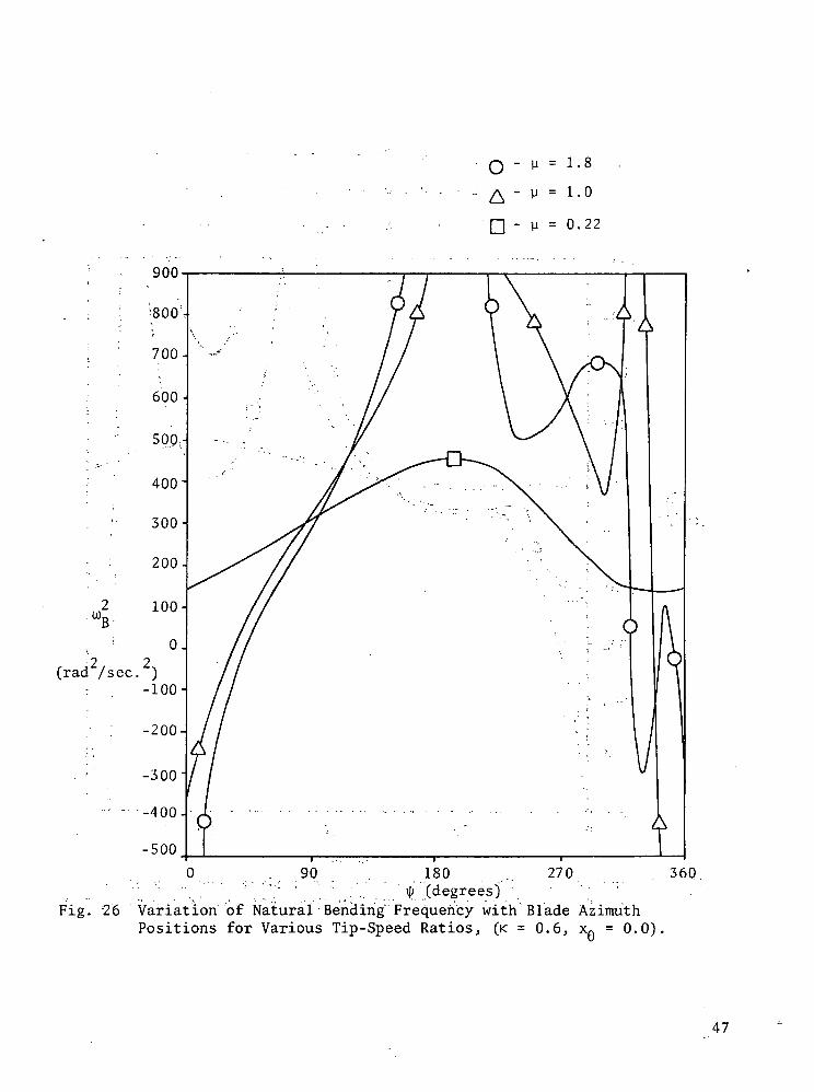
From the above results, the sensitivity of torsional characteristicsof the CH-34 blade was described for the blade operating speed (y = 0.22).Another important element of the investigation of torsional sensitivitycharacteristics of rotor blades is the changing flight conditions. Thetorsional and bending vibration frequencies and the coupling between themodes were calculated for different flight conditions and different po-sitions of the aerodynamic and elastic axes. Figures 22-27 indicate thechanges in the bending frequencies and coupling ratios with increasingforward speeds.
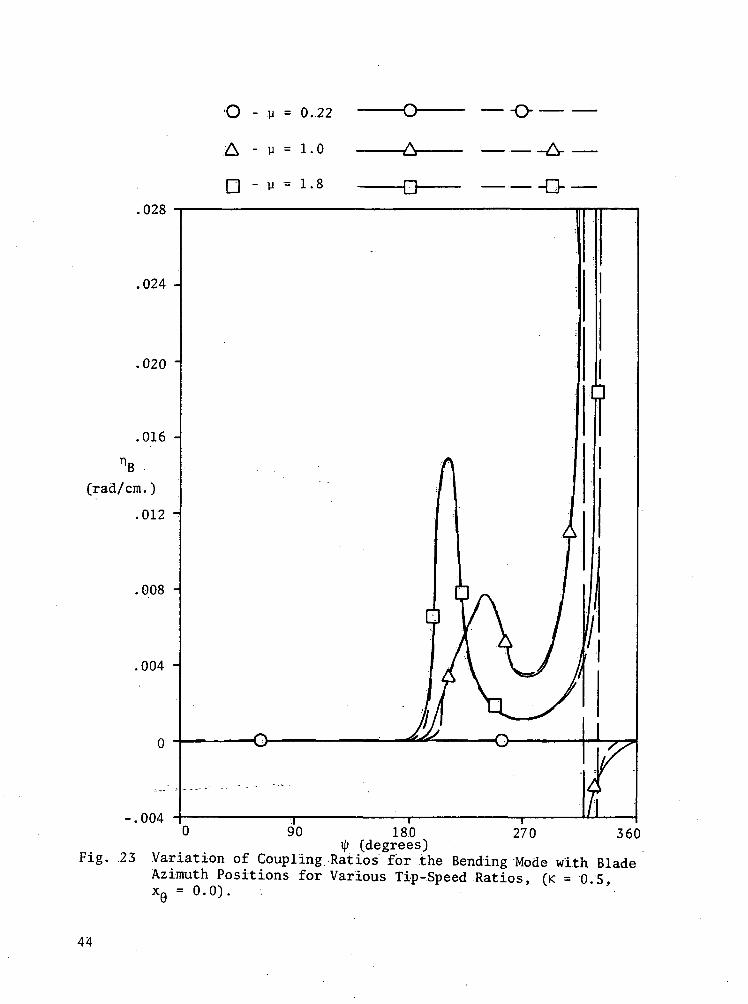
As the tip-speed ratio increases, the bending frequencies show a peri-odic variation with changing azimuth positions and the values of the fre-quencies are highest at the forward flow region. These results can beinterpreted again in terms of the values of bending stiffness in figure 2.The bending vibrations become unstable for azimuth position 90° < 4> < 180The frequencies in the reverse flow region remain relatively low. ForK = 0.5 the coupling ratio exists again only for the reverse flow region.Another possibility of instability for 270° < ty < 360° exists in the re-verse flow region due to the low torsional frequencies in this region.
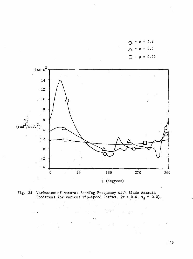
For K = 0.4 the effect of tip-speed ratios is considerably smaller in
o
13
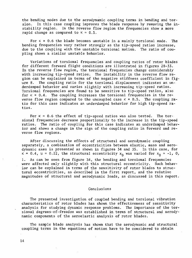
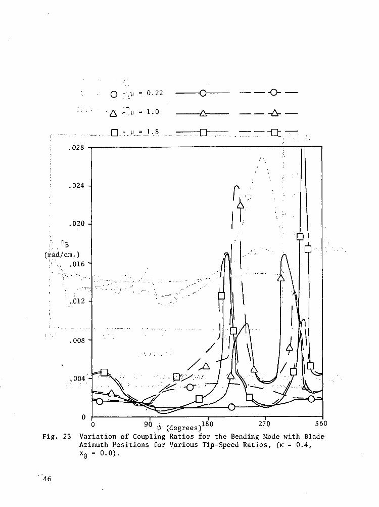
the bending modes due to the aerodynamic coupling terms in bending and tor-sion. In this case coupling improves the blade response by removing the in-stability region. In the reverse flow region the frequencies show a morerapid change as compared to K = 0.5.
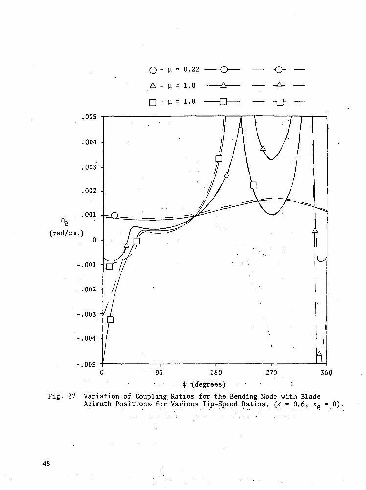
For K = 0.6 the blade becomes unstable in a mainly torsional mode. Thebending frequencies vary rather strongly as the tip-speed ratios increase,due to the coupling with the unstable torsional motion. The ratio of cou-pling shows a similar unstable behavior.
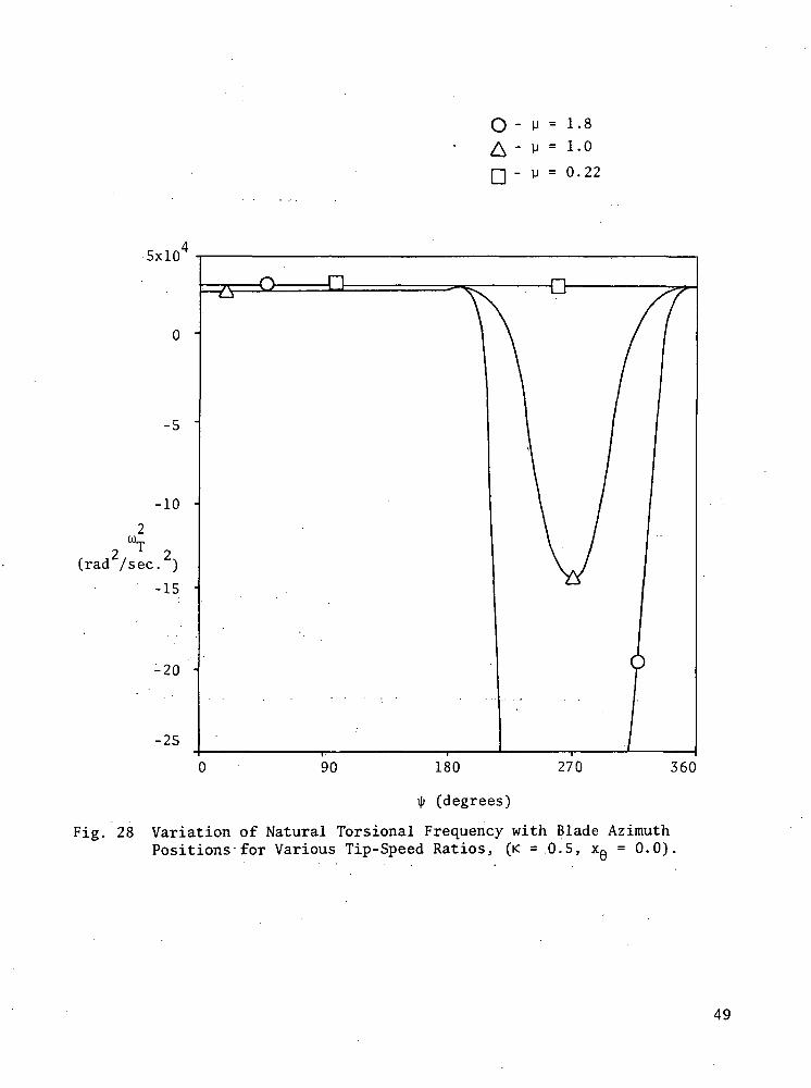
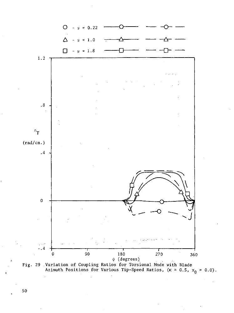
Variations of torsional frequencies and coupling ratios of rotor bladesfor different forward flight conditions are illustrated in figures 28-33.In the reverse flow region, the torsional frequencies change considerablywith increasing tip-speed ratios1. The instability in the reverse flow re-gion can be explained in terms of the negative stiffness coefficient in fig-ure 8. The coupling ratio for the torsional displacement indicates an un-derdamped behavior and varies slightly with increasing tip-speed ratios.Torsional frequencies are found to be sensitive to tip-speed ratios, alsofor K = 0.4. The coupling increases the torsional frequencies in the re-verse flow region compared to the uncoupled case K = 0.5. The coupling ra-tio for this case indicates an underdamped behavior for high tip-speed ra-tios.
For K = 0.6 the effect of tip-speed ratios was also tested. The tor-sional frequencies decrease proportionally to the increase in the tip-speedratios. The ratio of coupling for this case indicates an underdamped behav-ior and shows a change in the sign of the coupling ratio in forward and re-verse flow regions.
After discussing the effects of structural and aerodynamic couplingseparately, a combination of eccentricities between elastic, mass and aero-dynamic axes is presented as shown in figures 34 and 35. In this case, forK = 0.4, u = 0.22, the structural eccentricity XQ was varied for Xg = -1, 0,
1. As can be seen from figure 34, the bending and torsional frequencieswere affected only slightly with this structural eccentricity. Such behav-ior can be explained in terms of the sensitivity of rotor blades to struc-tural eccentricities, as described in the first report, and the relativemagnitudes of structural and aerodynamic loads, as discussed in this report.
Conclusions
The presented investigation of coupled bending and torsional vibrationcharacteristics of rotor blades has shown the effectiveness of sensitivityanalysis for studying dynamic response problems. The importance of the tor-sional degrees-of-freedom was established in terms of structural and aerody-namic components of the aeroelastic analysis of rotor blades.
The sample blade analysis has shown that the aerodynamic and structuralcoupling terms in the equations of motion have to be considered to obtain
14

realistic results for vibration frequencies and mode shapes. From the de-veloped sensitivity analysis of the mathematical model the significance ofblade design parameters can be determined and used to improve the bladeresponse and stability. The investigation has also shown the importance ofthe aerodynamic terms in the vibration analysis of blades in forward and re-verse flow regions at high tip-speed ratios.
15
APPENDIX
CALCULATION OF THE AERODYNAMIC LOADING IN FORWARD FLIGHT
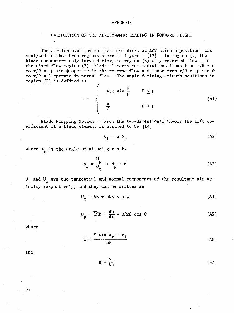
The airflow over the entire rotor disk, at any azimuth position, wasanalyzed in the three regions shown in figure 1 [13]. In region (1) theblade encounters only forward flow; in region (3) only reversed flow. Inthe mixed flow region (2), blade elements for radial positions from r/R = 0to r/R = -y sin 41 operate in the reverse flow and those from r/R = -y sin fyto r/R = 1 operate in normal flow. The angle defining azimuth positions inregion (2) is defined as
Arc
7T
2
BSin y B £ y
B > ye = < (Al)
Blade Flapping Motion: - From the two-dimensional theory the lift co-efficient of a blade element is assumed to be [14]
CL = a ar (A2)
where a is the angle of attack given by
ar = J. + 6p + 6 (A3)
U and U are the tangential and normal components of the resultant air ve-
locity respectively, and they can be written as
U = flR + yfiR sin ip (A4)
U = XJ2R + r - yftRB cos ty (AS)
where
V sin a - v.
and
V
16
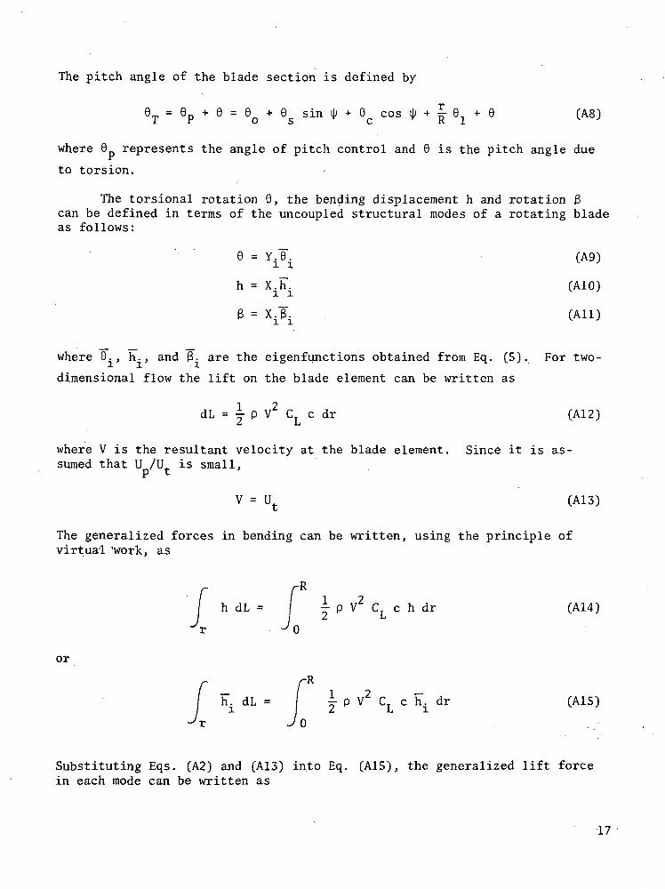
The pitch angle of the blade section is defined by
9T = 0p + 0 = 0Q + GS sin ip + 0c cos ty + £ QI + 0 (A8)
where 0 represents the angle of pitch control and 0 is the pitch angle due
to torsion.
The torsional rotation 0, the bending displacement h and rotation 3can be defined in terms of the uncoupled structural modes of a rotating bladeas follows:
0 = Y.J0". (A9)
h = X.h". (A10)
3 = XjlT (All)
where 0., h., and 3- are the eigenfunctions obtained from Eq. (5). For two-
dimensional flow the lift on the blade element can be written as
dL = y p V2 CL c dr (A12)
where V is the resultant velocity at the blade element. Since it is as-,sumed that U /U is small,
V = Ut (A13)
The generalized forces in bending can be written, using the principle ofvirtual 'work, as
-R
h dL = | ^ p V2 C. c h dr (A14)2 ij
0
or
-R
u dL = J j p V2 CL c hi dr (A15)
0
Substituting Eqs. (A2) and (A13) into Eq. (A15), the generalized lift forcein each mode can be written as
17
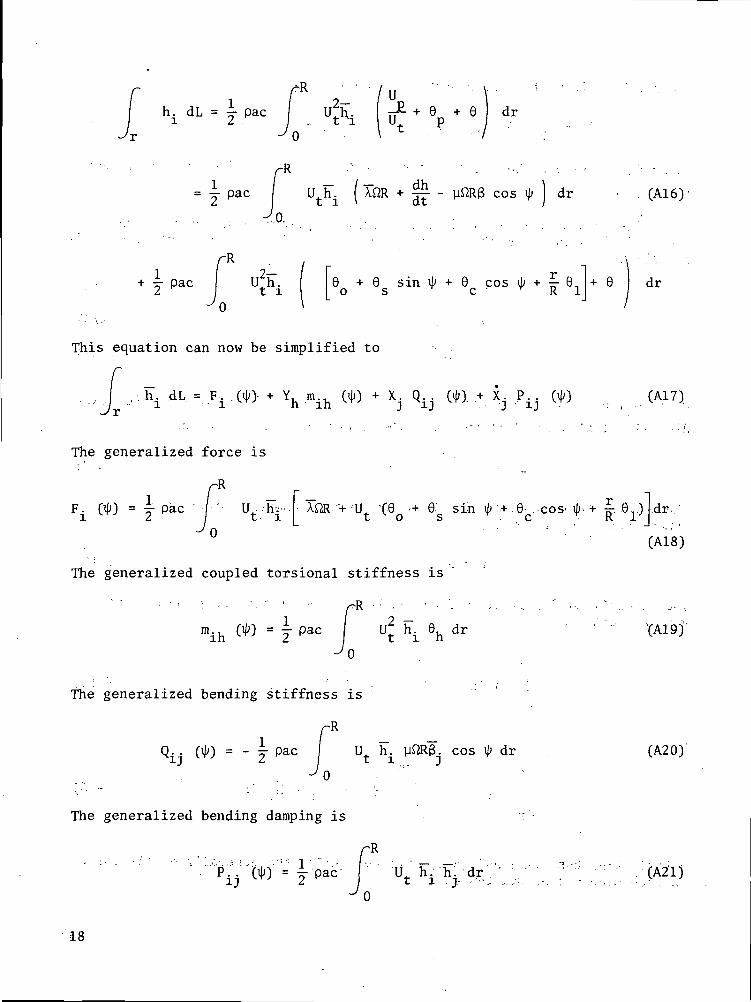
h. dL = -r- pac
-R
= pac U h± ( AflR + J£ - cos ^ dr (A16)
-R
v Pac ) + 6 sin \l> + 6 cos tj; + £- 0, + 9 drO S C K J .
This equation can now be simplified to
h. dL = F. (ijj> + Y, m.. (ij;) + X. Q. . WO + X. P.. 010i i ^J h ih vrj j xij ^Y-^ j ij ^r^ (A17)•
The generalized force is
F. 1 .- "+ 'U Sin
The generalized coupled torsional stiffness is
(A18)
mih!_2 hi 6h XA19J
The generalized bending stiffness is
12 U h. . cos \p dr (A20)
The generalized bending damping is
(A21)
18
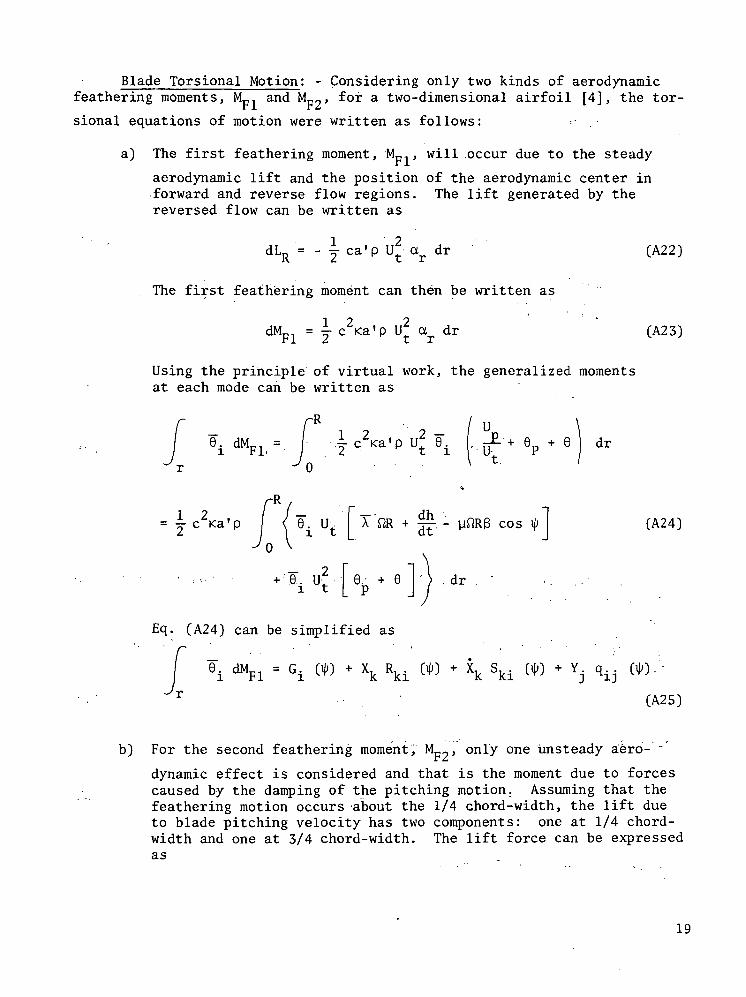
Blade Torsional Motion: - Considering only two kinds of aerodynamicfeathering moments, Mpl and Mp2, for a two-dimensional airfoil [4], the tor-
sional equations of motion were written as follows:
a) The first feathering moment, NL,, , will .occur due to the steady
aerodynamic lift and the position of the aerodynamic center inforward and reverse flow regions. The lift generated by thereversed flow can be written as
dLR = - j ca'p U2 ar dr (A22)
The first feathering moment can then be written as
dMpl = j c2Ka'p U2 ar dr (A23)
Using the principle of virtual work, the generalized momentsat each mode can be written as
-i c2Ka' U2 6 . + 6 +
(A24)
9i Ut 9p
Eq. (A24) can be simplified as
6. dMpl = G. (*) + Xk Rk. C« - \ Ski WO + Y. q..
CA25)
b) For the second feathering moment, Mp2, only one unsteady aero- ~
dynamic effect is considered and that is the moment due to forcescaused by the damping of the pitching motion. Assuming that thefeathering motion occurs about the 1/4 chord-width, the lift dueto blade pitching velocity has two components: one at 1/4 chord-width and one at 3/4 chord-width. The lift force can be expressedas
19
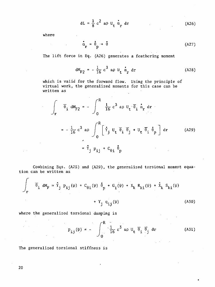
dL = y c2 ap U. a dr . (A26)O t *
where
a = 0 -+ 6 (A27)r p v '
The lift force in Eq. (A26) generates a feathering moment
dMp2 = - y^. c3 ap U ar dr (A28)
which is valid for the forward flow. Using the principle ofvirtual work, the generalized moments for this case can bewritten as
fR
6 i d M F 2 = - 16 C" ap Ut 9i «r dr
J0
rR13 / r • - - - • i
= - 4r c aP Y. U 8. 0. + U_ 6. 9 dr (A29)1 6 / I j t i j t i p lJ 0
(?
= Y. p.. + C0. 6i Fii 61 p
Combining Eqs. (A25) and (A29), the generalized torsional moment equa-tion can be written as
ei F = j PIJ^ - cei(W ep + G.W + xk Rki( + xk sk.
(A30)
where the generalized torsional damping is
R ~:16" °3 ap Ut 9i 9j dr (A31)
The generalized torsional stiffness is
20
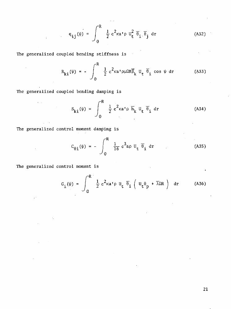
Rqi;jOIO = I yc 2 <a 'p U2 9i .0.. dr (A32)
The generalized coupled bending stiffness is
-RI ? _ _
R (ijj) = - ^c Ka'puftR$v U. 9. cos ijj dr (A33)KX \ 2, K L X
^o
The generalized coupled bending damping is
-R
j c2Ka'p hk Ut 9.. dr (A34)
0
The generalized control moment damping is
fRCei( ) = - I ye c3ap Ut 9t dr . (A35)
^0
The generalized control moment is
-R
~~ "" ' dr (A36)
21
REFERENCES
1. Bratanow, T., and Ecer, A.: Sensitivity Analysis of Torsional VibrationCharacteristics of Helicopter Rotor Blades, Part I, Aerodynamics andSensitivity Analysis. To be published as a NASA report.
2. Miller, R.H.: Rotor Blade Harmonic Airloading. AIAA J., Vol. 2, No. 7,July, 1964, pp.1254-1269.
3. Crimi, P.: A Method for Analyzing the Aeroelastic Stability of a Heli-copter Rotor in Forward Flight. NASA CR-1332, Aug., 1969.
4. Kuczynski, W.A., and Sharpe, D.L.: Hingeless Rotor Characteristics atHigh Advance Ratios. AIAA 4th Fluid and Plasma Dynamics Conference,Palo Alto, Calif., June 21-23, 1971.
5. Piarulli, V.J., and White, R.P. Jr.: A Method for Determining the Char-acteristic Functions Associated with the Aeroelastic Instabilities ofHelicopter Rotors in Forward Flight. NASA CR-1577, 1970.
6. Fisher, R.K. Jr., and McCroskey, W.J.: Detailed Aerodynamic Measure-ments on a Model Rotor in the Blade Stall Regime. Presented,at the27th Annual National V/STOL Forum of the Am. Helicopter Soc.,Washington, D.C., May, 1971.
7. Ham, N.D.: Aerodynamic Loading on a Two-Dimensional Airfoil duringDynamic Stall. AIAA J., Vol. 6, No. 10, Oct., 1968.
8. Ham, N.D., and Young, M.I.: Limit Cycle Torsional Motion of HelicopterBlades Due to Stall. J. Sound Vib., Vol. 4, No. 3, 1966, pp. 431-444.
9. Kuczynski, W.A., and Sissingh, G.J.: Research Program to DetermineRotor Response Characteristics at High Advance Ratios. NASA CR-114290, Feb., 1971.
10. Yntema, R.T.: Simplified Procedures and Charts for the Rapid Estima-tion of Bending Frequencies of Rotating Beams. NACA TN 3459, 1955.(Supersedes NACA RM L54G02).
11. Perisho, C.H.: Analysis of the Stability of a Flexible Rotor Blade atHigh Advance Ratio. J. of the Am. Helicopter Soc., Vol. 4, No. 2,April, 1959, pp. 4-18.
12. Sissingh, G.J.: Dynamics of Rotors Operating at High Advance Ratios.J. of the Am. Helicopter Soc., Vol. 13, No. 3, July, 1968, pp. 56-63.
13. Sissingh, G.J., and Kuczynski, W.A.: Investigations of the Effect ofBlade Torsion on the Dynamics of the Flapping Motion. J. of the Am.Helicopter Soc., April, 1970.
22
14. Gessow, A., and Myers, G. Jr.: Aerodynamics of the Helicopter.Frederick Ungar-Publishing Co., New York, 1952.
23
ino>-oo
13CD
OO
o
e
LOCMO
J -HnJ
toinrt
rt5n3-PO
<DN
rt
0>c
0)
•srH
CQ
toI
CD
O
^T
i— 1njCO
•H
0H
(/)
<t>""0osc•HT3C501
to
CM
rH
to
CM
J
CM •oCD</>
•00
.s
(N «0CDV)
•
'£50
CM CM1 1O O
X XC4 tf ^*tCTl 1 COLO O \OCM OO O
1
CM (N1 1o or-j 1
X X
oo rf t--1*- \Q fjrH O OO
• • •
1 1
CM CM1 10 0
"* xOl t" rHCTl CM CMtO iH CMoo to to
0 1
O O UO0 0 ^t0 0 •*O O 00
0 0 rH
O -vO Oo \o oo to o0 CT) 0
O iH O
o o o\o o orH O Oo o oto o o
rH CM tO
sap OHSuipuag
eCM •
oen•
W)w
CM•
o0(/)
•., W)
•
f-H1o"x
O O Olo o t-~O O LOO O CM
o o
,H
o"x
0 00 O0 vO OO \D O0 CM O
• • •o o
rH1oXf- 0 0rH 0 O00 O OCM 0 O
o o
CM CM1 10 0
X XCM r~- oCM CT) \Oto oo o .
CM iH N1 10 OrH IHX Xr-- o ^1-CM "* t-~-
•-H \0 Oto O oo
• • •1 1
CM (N1 10 O.i— 1 rHX X
CTl f CMtO 00 CTloo h~ LOO iH CM
O 1 1
^H (N »-O
S9pOW
TBUOTSJ101
24
§<ooC
•s6
LOCMO
CDX
10wCD
•H+Jcn
O r-l
§ *
W 101
T3 X0) U
cd
0> 0)c -a<D O
oS
To
rsi o
n a
l
in
oSbOC
•H
C
CO
to
CM
i— 1
to
CM
i-H
bi
bO
to to to0 0 0
X X Xt-~ O CMO \D OO•>* CT> ol— 1 l— 1 i-H '
1 1
tO CM i-lO O O
X X X
•f CM tO•"Jf \D LOr-l t~~ tO
1
CM i-H i-l.0 0 0
X X X00 vO tor^ to \oto \o r*-•*t CM O
1 1 1
o o r--O O i-l
'O O I-Ho o \oo o CM
to01— 1X
O CM OO \O 0o to oo •* oO . 00 O
too1— 1X
00' 0 OLO O Oo o oOO O O . -
i-H O O
,'i-H CM tO
SuTpugg
6
bb
bb
oX
o o cr>0 0 i-HO O CMo o oO O CM
too
. Xo •<* oO CM O0 to 0O CM O
o t-» o
CM0 .
Xt-- o o0 0 0CM O Orf O O
00 O O
i— 1 • i-l too o oX X . X
IO CM CM\o to oor~- LO oO to i— 1
1 1
i— 1 CM tO0 0 0i-l i— 1 r-lX X X
vO O OtO CM \O
CM r~ i— i
CM to to0 0 01— 1 • I-l 1— 1X X X
oo • 01 r-I ~ " ("**f) tj- tf*$• I-l 1— 1
1 1 1
• i— 1 CM to
IBUOTSJOX
25
V)If)
'O§
ca
50
03O
• H-p•H^H
CJ
rtfn
4->O
CO
13a)
CD CDC 130) asU r-l
CO
CD
OO
sca
to
U
o
in13O
i— iOSco•rHi/ifHO
18oSbOC•H• OcCDoa
to
CM
•-H
to
CM
'i-H
6CM
. u0)(fl >• • .bO
^• « — /
/ — \
CM
O0)." -
. •bO.i — •
CM• 0
XCMCMv6O
CM '0rHXCMi-H0CM•
.
CM0
XvOLOto
*•
LOrff00
•— 1
o
°J .I—I
0\o1-40
•to
• Ha
s: O
CD
- *••bO
v^— '
.6
o0)10
•
bo
^V '
oXvOto .1— 1
oXoLOfto. .
"*
0
X'entoto
.i-H
CMo .r— 1 -..X00
ooto
''CNOi-HX• fCMLOLO
CM
CMO
'• xLOt^ ~
"*
: i-H
•rHCQ.
E*'
biX '
/ — Ne
£Pv_y
: 1 ' '
tO
X00
^ooi-H
to*
LOOi— 1 :X ,
00to .i-H, •
i-H
VOO
"x•-HvOCMtoi-H
Oi-H
,xi-Hi-H
CM
toOi-HXCM
1.
00
i— iO
X00LOo00
i-H
•H
26
oO
rt
*H•O
0inf-i0
0
(D(1)
•s
IfHO
PL,
013rt
i— iOQ
O•p
cs .o•HM0a!
o
0•
1 bO•H
27:
0.2 -
- Q2,1
- Q2,2
3,1
(degrees)
Fig. 2 Variation of Aerodynamic Bending Stiffness with Blade AzimuthPositions, (y = 0.22, K = 0.5, X = 0.0).
0.4 -
0.3 -
0.2 -
P", •
0.1
0.0
- P3,1
90 270 360180T\> (degrees)
Fig. 3 Variation of Aerodynamic Bending Damping with Blade AzimuthPositions, (y = 0.22, K = 0.5, XQ = 0.0).o
28
0.4
0.3 '
1/2 pac ft2 R3
oAD
- m
- m
- m
- m
- m
- m
1,3
2.'l
2,2
3,1
0.0
360180 270
- 41 (degrees)
Fig. 4 Variation of Aerodynamic Bending Coupling with Blade Azimuth. Positions, (u = 0.22, K = 0.5, XQ = 0.0).
1.5
Q = Q 1/2 pac n R1,1 i, i
360
ij; (degrees)
Fig. 5 Aerodynamic Stiffness in First Bending Mode at Various AdvanceRatios, (K = 0.5, XQ = 0.0).
. 29
P = P /1/2 pac fl R'1,1 i,i,
"1.1
270 360180iji' (degrees)
Fig. 6 Aerodynamic Damping in First Bending Mode at Various Advance Ratios,(K = 0.5, xfl = 0.0).
. ; 2.8 °
2.4
"- 2.0
m., 1.6
1.2
0.8
0.4
0.0
-0.4 J90 1?80
(degrees)360.
Fig.:71 Aerodynamic Stiffness :Coupling,of First.Torsional and First BendingModes at Various Advance Ratios, (K = 0.5, XQ = 0.0).
30
900.0
(degrees)
180 270 360
-0.1 .
_-0.2 -
'1,1-0.3 -I
-0.4 •
-0.5 .
q,. , = qr .11/2 pa' c2 < ft2 R3
StructuralStiffness
y =• 1.8
Fig. 8 Aerodynamic Stiffness ,for First Torsional Mode with Various AdvanceRatios, (K = 0.5, XQ = 0.0).
1.2
1.0^ . * ,
_0.8Pl,l0.6
0.4
0.2
0.0
y = 1.8Structural Critical
Damping
90 180 270
4/-.(degrees)
360
Fig. 9 Aerodynamic Damping for,.First Torsional Mode with Various AdvanceRatios, (K = 0.5, XQ = 0.0).
31
0.5
0.4 .
0.3
0.2
0.1
R = R /1/2 pa' c2 K Q2 R2J-, l 1,1 y = 1.8
90 180
• \l> (degrees)
360V0'0
-0.1
-0.2
-0.3 .
-0.4 .
-0.5
Fig. 10 Aerodynamic Stiffness of First Bending and First Torsional Modes atVarious Advance Ratios, (K = 0.5, XQ = 0.0).
0.4
0.3
0.2 .
0.1 -
1,1
0.0
U = 1.8= Sn , 71/2 pa.1- c K B R
90 180 270 360
-- ..-.-•. •';•!.••.'-: • ;'^ -'( degrees) :-l"• '• v';' • •''•'* '• -;' '•
Fig. 11 Aerodynamic Damping Coupling*of First Bending and First TorsionalModes at Various Advance Ratios, (K = 0.5, xfl = 0.0).
32
Damping Factor
Natural Bending Frequency
-10-
-20-
-50-
2000
1000
0),.
(rad /sec. )
--1000
- -2000
-3000
45 90 135- 180 225- 270 315 360
ij> (degrees)
Fig. 12 Variation of Natural. Bending Frequency and Damping FLatio withBlade Azimuth Positions, (u = 0.22, K = 0.5'., xfi.= 0.0).
33
Damping Factor
Natural Torsional Frequency
7.0
6.0-
5.0
4.0-
3.0-
2.0-
1.0.
-3x10
-2
radsec.
-1
0 45 90 135 180 225 270 315 360
ty (degrees)
Fig. 13 Variation of Natural Torsional Frequency and Damping "Ratio withBlade Azimuth Positions, (u = 0.22, K = 0.5, x. = 0.0).
9
34
1.2x10⁻⁵
.8-
.4 -
"B
(rad/cm)
-.4
Bending
Torsion --A--
I11V
1.2
- .8
f' -.4
(rad/cm.)
-.445 90 135 180 225 270 315. 360
ip (degrees)Fig. 14 Variation of Coupling Ratios for the Torsional and Bending Modes
with Blade Azimuth Positions, (u = 0.22, K = 0.5, XQ = 0.0).
35
2500
2000-
1500
2 1000-WR
2 2(radVsec/)
500
-500'
-1000'
oAD
- xe =
- xe =- x,. =
-0.025
0.0
0.025
2JB
2UT
90
70x10
60
- 50
- 40
30 ^2
2 2(rad /sec. )
u 20
10
-0
180
(degrees)
270 360
Fig. 15 Variation of Natural Bending and Torsional Frequencies with BladeAzimuth Positions for Various Eccentricities between Elastic andMass Axes, (y = 0.22, K = 0.5).
36
O - x. = 0.025 -a -o
2x10⁻⁵
1.5 -
1.0 -
.5 -
nB(rad/cm.)
0
-.5 -
-1.0
= 0.0
- x. = 0.025
O
90 180
-D-
270 360
ty (degrees) ., •Fig. 16 Variation of Coupling Ratios for the Bending Mode with Blade
Azimuth Positions for Various Eccentricities between Elasticand Mass Axes, (u = 0.22, K = 0.5).
37
o - x. = 0.025 -o
-o-
D
\
.0 ,90 270
.04
--.04
(rad/cm.)
--.08
s— .12
-.16
360•180i|» (degrees)
Fig. 17 Variation of Coupling Ratios for the Torsionai Mode with Blade.-^Azimuth Positions for Various Eccentricities between Elastic.-.,.;-and Mass Axes,.. (y = 0.22, K= 0.5).
38
3x10'
: 1 -°B
2' 2(rad /sec. )
0 -I
O - K = 0-4
A - K = o.sQ - K = 0.6
180
i|; (degrees)
270 .360
Fig. 1-8- Variation of Natural Bending Frequency with Blade AzimuthPositions for Various Eccentricities between Elastic and Aero-dynamic Axes, (u = 0.22, XQ = 0.0).
39
3.3x10
-.3.- •• .0. .90 . 360:'-;.--.,-,-' 180 •;;• ; ~ ••- ,-270 -., -...
• • . • . • . ; . • : > - ' . - - , - : . t y (degrees.) ,:..,.;: - , : . . . - . •- • :Fig. 19 Variation of Coupling Ratios .for the Bending Mode with Blade
Azimuth Positions for Various Eccentricities between Elasticand Aerodynamic Axes, (u = 0.22, xfi = 0).
40
2x10
1 .
0 -
-1
-2 -|
2(l)m TT1 "" O
(rad2/sec.2)-4 .
- K = 0.4
- K = 0.5
- K = 0.'6
3x10
90 180
(degrees)
270 360
Fig. 20 Variation of Natural Torsional Frequency with Blade AzimuthPositions for Various Eccentricities between Elastic and Aero-dynamic Axes, (y = 0.22, XQ = 0.0).
41
O - K = 0.4 O-
A - K = 0.5
- K = 0.6 -- D-
(rad/cm.)
-. 04 -
-.20-
-.2490 270 360180
ty (degrees)Fig. 21 Variation of Coupling Ratios for the Torsional Mode with Blade
Azimuth Positions for Various Eccentricities between Elasticand Aerodynamic Axes, (y = 0.22, XQ = -0.0).
42
3x10
-3
90
-s.-:.. o- v = 1.8
. A- y = 1.0
D- p = 0.22
180
(degrees)
270 360
Fig. 22 Variation of Natural Bending Frequency with Blade AzimuthPositions for Various Tip-Speed Ratios, (K = 0.5, XQ ='. 0.0).
43.
,028
,024 -
.020 -
.016 -
nB(rad/cm.)
.012
,008 -
.004 -
0
-.0040 270 360180
4> (degrees)Fig. .23 Variation of Coupling Ratios for the Bending :Mode with Blade
Azimuth Positions for Various Tip-Speed Ratios, (K = 0 5XQ = 0.0).
44
0
A
= 1-8
- • y = 0.22
16x10"
14
12.
. 10
8
2 2(rad /sec. )
0
-2
-4
90 180
(degrees)
270 360
Fig. 24 Variation of Natural Bending Frequency with Blade AzimuthPositions for Various Tip-Speed Ratios, (K = 0.4, xfl = 0.0)
45
.028
.024 -
(rad/cm.)•"-:. .016-
0
O --,y = 0-22
-A .-~!u = l.O
O
— — rQ:
o 180 270 360ip' (degrees)Fig. 25 Variation of Coupling Ratios for the Bending Mode with Blade
Azimuth Positions for Various Tip-Speed Ratios, (K = 0.4,XQ = 0.0).
46
O - V = 1.8
A - y = i.o
D - u = 0.22
.0).B
(racl /sec. )
-500
90 270180•'•••• • '•- • ' ty (degrees) '
Fig. 26 Variation of Natural•Bending" Frequency with Blade AzimuthPositions for Various Tip-Speed Ratios, (K = 0.6, XQ = 0.0)
360
47
n
.005
.004 -
.003 -
.002 -
.001 - =.B
(rad/cm.)0 -
-.001 •
-.002 -
-.003 -
-.004 -
-.005180 270 360
— ~ ty (degrees)
Fig. 27 Variation of Coupling Ratios for the Bending Mode with BladeAzimuth Positions for Various Tip-Speed Ratios, (K = 0.6, xfl = 0)
48
5x10
0 -
-5
-10
(rad2/sec.2)
-15
-20 -
-25
-O-
O - y = 1-8
A - v = i-o- p = 0.22
90 180
(degrees)
270 360
Fig. 28 Variation of Natural Torsional Frequency with Blade AzimuthPositions-for Various Tip-Speed Ratios, (K =0.5, X = 0.0).
49
1.2
.8 -
(rad/cm.)
.4
-.4
O - y = 0.22
A - v = 1.0
D - y = 1.8
o
-D- -O
o 90 270 360180ty (degrees)
Fig. 29 Variation of Coupling Ratios for Torsional Mode with BladeAzimuth Positions for Various Tip-Speed Ratios, (K = 0.5, xfl = 0.0)
50
3xl05 H
0)
2 2(rad /sec. )
6 H
-1
-2
O - V = 1.8
A - Vi = 1.0
D - V = 0.22
90 180
(degrees)
270 360
Fig. 30 Variation of Natural Torsional Frequency with Blade AzimuthPositions for Various Tip-Speed Ratios, (K = 0.4, XQ = 0.0).
51
.21
.18-
.15-
.12-
nT .09-
(rad/cm.)
.06-
.03-
0-
-.03-
-.06-
o
-D-
90 180(degrees)
270 360
Fig. 31 Variation of Coupling Ratios for the Torsional Mode with BladeAzimuth Positions for Various Tip-Speed Ratios, (K = 0.4, XQ = 0)
52
1x10
WT 0-2 2(rad /sec. .)
O - v = 1.8
A - w = i.o
Q - W = 0.22
90 180
i|) (degrees)
270 360
Fig. 32 Variation of Natural Torsional Frequency with Blade AzimuthPositions for Various Tip-Speed Ratios, (K = 0.6, XQ - 0.0).
53
O - u" = 0.22
A - u = 1.0 £r
D - ii = 1.8 D-
-O-
-D-
90 180 • '•••" 270
(degrees)
• • ' • ' 360
Fig. 33 Variation of Coupling Ratios for the Torsional Mode with BladeAzimuth Positions for Various Tip-Speed Ratios, (X = 0.6, X = 0.0)
54
O - *e = 0.025
A - X9 = °-°
D - x = .-0.025
2600
CJ.-
2 2(rad /sec. )
0 180
14x10
- 13
12
- 11
2 2(rad /sec. )10
270 360
<Jj (degrees)
Fig. 34 • Variation of Natural Bending and Torsional Frequencies with BladeAzimuth Positions for Various Eccentricities between Elastic andMass Axes, -(y = 0.22, K = 0.4).
55
n
.0035
.0030 -
.0025 -
.0020 -B(rad/cm.)
.0015 -
.0010 -
.0005 -
O - xQ = 0.025
A - XQ = 0.0
Q - x0 = -0.025
-O
-D-
360
Fig. 35 Variation of Coupling Ratios for the Bending Mode with BladeAzimuth Positions for Various Eccentricities between Elasticand Mass Axes, (u = 0.22, K = 0.4).
56 NASA-Langley, 1974
NATIONAL AERONAUTICS AND SPACE ADMINISTRATION
WASHINGTON, D.C. 2O546
OFFICIAL BUSINESS
PENALTY FOR PRIVATE USE S3OO SPECIAL FOURTH-CLASS RATEBOOK
POSTAGE AND FEES PAIDNATIONAL AERONAUTICS AND
SPACE ADMINISTRATION451
POSTMASTER : If Undeliverable (Section 158Postal Manual) Do Not Return
"The aeronautical and space activities of the United States shall beconducted so as to contribute . . . to the expansion of human knowl-edge of phenomena in the atmosphere and space. The Administrationshall provide for the widest practicable and appropriate disseminationof information concerning its activities and the results thereoj."
—NATIONAL AERONAUTICS AND SPACE ACT OF 1958
NASA SCIENTIFIC AND TECHNICAL PUBLICATIONSTECHNICAL REPORTS: Scientific andtechnical information considered important,complete, and a lasting contribution to existingknowledge.
TECHNICAL NOTES: Information less broadin scope but nevertheless of importance as acontribution to existing knowledge.
TECHNICAL MEMORANDUMS:Information receiving limited distributionbecause of preliminary data, security classifica-tion, or other reasons. Also includes conferenceproceedings with either limited or unlimiteddistribution.
CONTRACTOR REPORTS: Scientific andtechnical information generated under a NASAcontract or grant and considered an importantcontribution to existing knowledge.
TECHNICAL TRANSLATIONS: Informationpublished in a foreign language consideredto merit NASA distribution in English.
SPECIAL PUBLICATIONS: Informationderived from or of value to NASA activities.Publications include final reports of majorprojects, monographs, data compilations,handbooks, sourcebooks, and specialbibliographies.
TECHNOLOGY UTILIZATIONPUBLICATIONS: Information on technologyused by NASA that may be of particularinterest in commercial and other non-aerospaceapplications. Publications include Tech Briefs,Technology Utilization Reports andTechnology Surveys.
Details on the availability of these publications may be obtained from:
SCIENTIFIC AND TECHNICAL INFORMATION OFFICE
N A T I O N A L A E R O N A U T I C S A N D S P A C E A D M I N I S T R A T I O N
Washington, D.C. 20546