Embed Size (px)
Citation preview
Sensitivity Analysis of Characteristic Parameters
of Railway Electric Traction System
Rachana Garg and Priya Mahajan Deptt. of Electrical Engg., Delhi Technological University, Delhi, India
Email: [email protected], [email protected]
Parmod Kumar (IRD), Maharaja Agrasen Institute of Technology, Delhi, India
Email: [email protected]
Abstract—The modal analysis, which decouples the contact
wire and rail track conductors, is used to develop an
integrated model of single rail track and contact wire. The
characteristic impedance and propagation constant matrices
of integrated model have been computed. The authors have
studied effects of various parameters of interest on
characteristic impedance and propagation constant using
sensitivity analysis. The sensitivity functions of series
impedance and shunt admittance related to contact wire and
catenary have been developed and validated in this paper.
Index Terms—railway traction lines, characteristic
parameters, sensitivity analysis, parameter sensitivity
I. INTRODUCTION
Railway electric traction system is a fast and green
transportation system with enhanced load carrying
capacity. The analysis and design of power and signaling
system of railway electric traction system needs
mathematical model of the system. The authors in this
paper have used the multi-conductor transmission line
theory to develop the mathematical model of the electric
traction system and to compute the characteristic
impedance and propagation constant of this system. This
approach can then be extended to find the voltage and
current distribution of the system. The characteristic
impedance and propagation constant are the functions of
line parameters i.e. self and mutual impedances and
admittances of contact wire and rail track. The numerical
values of these parameters are not accurately known
under practical conditions as they are dependent on
varying/uncertain parameters like permeability, supply
frequency and shape of the conductor. In order to study
the effect of these uncertain parameters on the
characteristic parameters of the railway electric traction
system, the authors have carried out the sensitivity
analysis of characteristic impedance and propagation
constant with respect to the above mentioned parameters
of interest for the first time in the literature. In a rail track
ferromagnetic material, both saturation and hysteresis are
Manuscript received September 21, 2013; revised January 23, 2014
observed. This affects the permeability of rail track. The
permeability also depends upon the composition of rail
track material which may not remain constant throughout
the length of the track. Further, to enhance the
performance of the traction system, it is desirable to
consider a conductor with a cross-section that will
produce uniform magnetic field on its surface. Also, the
supply side contains the harmonic frequency components
due to the power electronic devices which are inherent to
the modern electric traction drives. The variations in
these parameters of interest motivated the authors to carry
out the sensitivity analysis of characteristic parameters of
the system wrt these parameters.
The complete mathematical model of railway electric
traction lines, which include the contact wire and rail
track, has received little attention in the literature. Most
of the traction studies are limited to railway track
modeling. R.J. Hill et al. [1] has computed frequency
dependent self and mutual admittance for a single track
power-rail, considering it as a distributed transmission
line. They have computed the impedance by numerical
calculations and compared with analytic impedance
models based on the Carson eqns. for a stratified weakly
conducting ground. A. Mariscotti has applied multi
conductor transmission lines theory to railway traction
system to find the distribution of the traction return
current in AC and DC electric railway systems and
carried out sensitivity analysis of rail current and rail to
rail voltage wrt parameters of interest [2]. He has also
carried out modeling of track circuit signaling system
which may be helpful in automatic train control [3].
Measurement of currents at power-supply frequency and
validation of a multi-conductor transmission-line model
is done for (2x25kV) electric railway system with
autotransformer [4]. An electromagnetic field model for
identification of distributed self and mutual shunt
admittances using multi-conductor transmission lines
(MTL) is formulated and used to study the parametric
behavior of single track admittance [5]. Andrea
Mariscotti et al. [6] have analyzed the published
experimental data and formulae for the determination of
the electric parameters of railway traction lines. He
observed that the experimental results conform with the
8
International Journal of Electronics and Electrical Engineering Vol. 2, No. 1, March, 2014
©2014 Engineering and Technology Publishingdoi: 10.12720/ijeee.2.1.8-14
calculated results in frequency range of 50Hz-50 kHz. He
also focused on the CCITT simplified method for the
evaluation of induced voltages in electric traction system
[7].
II. CONFIGURATION OF RAILWAY ELECTRIC
TRACTION LINES
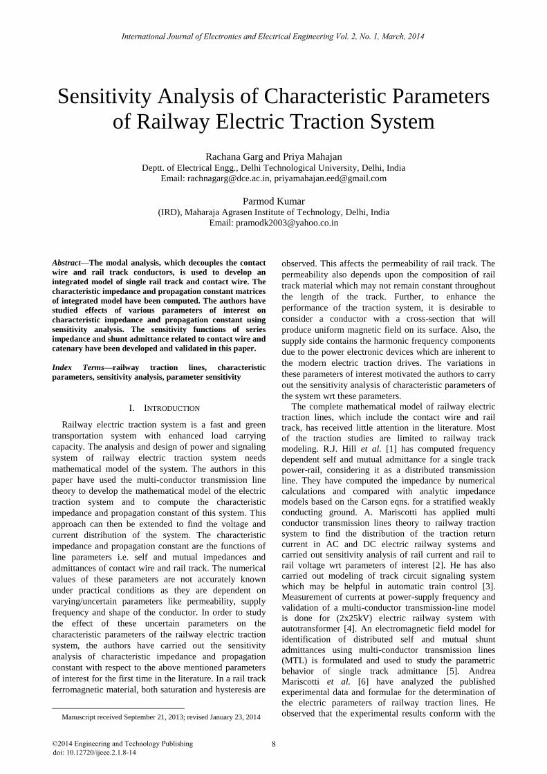
In modern overhead electric traction system, the
catenary is fed at 25kV, 1-phase ac through the feeding
posts which are positioned at frequent intervals alongside
the track. The catenary energizes the contact wire which
is kept at constant height and in the right position with the
help of droppers. The pantograph, a high-strength tubular
steel structure which can be raised or lowered, is used to
make contact with the overhead contact wire to draw
energy to feed the drives of the locomotive. Fig. 1 shows
the physical model of railway electric traction system.
Figure 1. Physical model of railway electric traction system
III. MATHEMATICAL MODEL
A mathematical model based on the electromagnetic
properties of rail track is necessary for the analysis and
design of railway electric power and signaling systems.
The studies related to propagation of voltages and
currents signals over the railway electric traction lines
need the series impedance and shunt admittance matrices
per unit length. These matrices state the electrostatic and
electromagnetic performance of the system and depend
on the physical and electrical characteristics of the rail
track conductor, the geometric arrangement of the
conductors and rail track, height above the earth level,
permeability and the earth resistivity [8]. The accuracy of
the result depends, therefore, on accuracy with which the
basic series impedance and shunt admittance matrices of
railway electric traction system have been formed.
A. Series Impedance Matrix
The series impedance matrix, Z can be given by (1)
Z = Rc + Re + j (Xc+Xe+Xg) (1)
where suffix ‘c’ denotes the quantities relating to
conductor, ‘e’ denotes the quantities relating to earth and
‘g’ denotes the quantities relating to geometric
arrangement of the conductors The resistance matrix Rc is
a diagonal matrix whose off diagonal elements are zero.
The resistance of the catenary conductor, Rc11,is given by
(2),
Rc11= (2)
where Ro is dc resistance of the conductor, is skin
effect ratio and is given by (3) :
√(
)
√
(3)
where d is the diameter of catenary in mm, is frequency
of supply in Hz, µ is permeability of conductor material
and ρ is the resistivity of material in micro-ohm cm.
The resistance of rail track conductors, Rc22 and Rc33 is
given by (4)[9]:
Rc22=Rc33=
[
√ (
)] [
] (4)
where, σr is the conductivity of rail track, θ is the
hysteresis angle , δr is skin depth and ‘a’ is the equivalent
radius of rail track and may be calculated considering the
rail track as an equivalent I structure[9].
(5)
The reactance of track conductors Xc22 and Xc33 is
given by (6)[9].
Xc22=Xc33=
[√ (
)] [
] (6)
The resistance and reactance due to earth path, Re and
Xe, are computed using Carson’s formula [10] given by
(7.1) and (7.2) respectively.
Re = [10(-4)
(8 π P f)] (7.1)
Xe = [10(-4)
(8 π Q f)] (7.2)
P and Q are calculated using Carson’s series [10] in
terms of two parameters cij and the angle subtended
between the conductor and the image, θij.
Inductive reactance due to geometry of conductors
above the ground, Xg is given by (8.1),
Xg =2πf (μ0μr) F (8.1)
where, F is Maxwell’s coefficient matrix, whose elements
are given by (8.2),
ln(2Hi/ri), i=1,2,3 ; ln(xij/uij), i =1,2,3, j=1,2,3, i≠j (8.2)
Each term in the matrix represents the distance
between two conductors or the conductor and the image .
B. Shunt-Admittance Matrix
The shunt-admittance matrix, Y is a function of the
physical geometry of the conductor relative to the earth
plane. Further, because the rail track conductor is on the
ground, it has appreciable leakage currents while the
catenary conductor is located at a sufficient height from
the ground and from the rail track conductors hence the
leakage currents from catenary to ground and from
catenary to rail conductors are assumed to be zero [8].
The admittance matrix is given by (9):
9
International Journal of Electronics and Electrical Engineering Vol. 2, No. 1, March, 2014
©2014 Engineering and Technology Publishing
Y=G + jωC (9)
where, G is the conductance matrix. The elements of
conductance matrix corresponding to the catenary are
zero and the elements corresponding to rail track are
given by (10) [5].
g22 = g33 =
⁄; g23 = g32 =
(10)
where, σr is conductivity of rail track, b is distance
between two rail track.
The capacitance matrix [C] is given by (11) ,
[C] = 2πε0 [F]-1
(11)
IV. MODAL THEORY
In order to compute the characteristic parameters of
railway electric traction lines, modal theory has been
applied to decouple the phase quantities to modal
quantities using the transformation given by(12)[11]-[12].
Pq=λq (12)
where, P is the product matrix and is given by (13)
P=[Z][Y] (13)
λ is the eigen value of P and q is the corresponding
eigen vector.
Thus, as given by (14), phase voltage and currents can
be transformed into modal quantities which make the
product matrix [Z][Y] diagonal.
[Q]-1
[Z] [Y][Q]= [λ] (14)
where [Q] is the transformation matrix of phase voltages,
constituted by the eigenvectors associated with each of
the eigen values, λi , of [P]= [Z] [Y]. The eigen value
matrix, λ can be given by (15),
[λi ]=diag(λ1, ....,λn) (15)
The propagation constant of the kth
mode is equal
to the square root of the kth
eigen value of [Z] [Y] and is
given by (16),
= λk1/2= α
(k) + jβ
(k) (16)
where, α(k)
is the attenuation constant and β(k)
is the phase
coefficient. The phase velocity v(k)
is obtained from (17)
v(k)=ω/β
(k) (17)
where ω is the angular velocity of phase voltages.
The characteristic impedance Z0, is given by (18)
Zo =√ ⁄ =Q λ-1/2
Q-1
Z (18)
V. PARAMETER SENSTIVITY
Sensitivity analysis is an effective method to predict
the effect of a parameter on the response of the system.
Mathematically, it is given by (19) [13]:
=
⁄
⁄ (
) (
)
(19)
The (19) is applicable for small parameter variations;
however, for large parameter variations the same
equation can be used in steps, assigning small variations
to the parameters until the values corresponding to the
system are reached. In any physical system, generally
more than one parameter changes simultaneously, for eg.,
in railway traction system the permeability of the rail
track, the earth resistivity, the supply frequency and
height of the catenary conductor etc. change
simultaneously. Therefore, in order to carry out the
complete sensitivity, the Jacobian matrix can be
developed as given by (20).
1 1 1 2 1
: :0
1 2
i
NF
P
NA A A
F P F P F PJ
F P F P F P
(20)
A. Sensitivity Functions
The normalised sensitivity of characteristic impedance,
and propagation constant, with respect to the
generic parameter xi is given by (21) – (24),
(21)
(22)
where,
[ ]
=
⁄
[ ]
⁄ ⁄ ⁄
[ ]
) (23)
[ ]
=
⁄
[ ]
⁄ ⁄ ⁄
[ ]
) (24)
In order to determine the normalised sensitivity of
and , the sensitivity functions of [Z] and [Y] are
calculated as given by (25) and (26) respectively,[11]
[ ] =
[ ]
=
+
+(
+
+
) (25)
[ ] =
[ ]
=
+(
); i=1,2, .....,Np (26)
where Np represents the number of parameters of interest.
From (13), the sensitivity functions of the matrix [P] are
obtained as given by (27):
[ ]=[
] [Y] + [Z] [ ] (27)
The sensitivity matrix of [P] is used to find the
sensitivities of all the eigen values λk of [P], as given by
(28) [14],
[ ] =
{[ ][ ]} [ ]
[ ] [ ] (28)
where [Qk], [Sk] are the eigenvectors of [P] and [Pt]
respectively, associated with the eigen value λk , and the
asterisk indicates the scalar product of two vectors.
From (16), the sensitivity functions of the modal
propagation constants are given by (29)-(32),
=
(2γ(k)
)-1
(29)
(30)
10
International Journal of Electronics and Electrical Engineering Vol. 2, No. 1, March, 2014
©2014 Engineering and Technology Publishing
(31)
=
(32)
Finally, the normalised sensitivity functions are
obtained as given by (33) - (35):
(33)
(34)
=
(35)
VI. NUMERICAL RESULTS
The characteristic parameters of the system are
computed using the specifications for catenary and rail
track as given in Appendix A. Using (12)- (18), the
characteristic impedance, Zo, propagation constant, , and
modes of propagation are computed and presented in
Table I, II and III.
TABLE I. CHARACTERISTIC IMPEDANCE MATRIX
TABLE II. PROPAGATION CONSTANT
(/m) [ ]
(/m) [ ]
TABLE III. MODES OF PROPAGATION
Ground Mode Aerial Mode I Aerial Mode II
From the Table III, it is observed that there are three
modes of propagation for a catenary and rail track lines as
shown in Fig. 2. The three modes are independent to each
other. The mode related to maximum attenuation and
lowest velocity of attenuation is called ground mode
whereas the mode having minimum attenuation and
maximum velocity is called aerial mode 1 and the other is
called aerial mode 2. For ground mode, current is flowing
in all of the three conductors. In aerial mode 1, only two
outer conductors take part in signal propagation. Here
current is entering the rail track conductor 2 and leaving
through rail track conductor 3. As the resistivity of
catenary conductor is much smaller as compared to rail
track, current coming out from catenary is much higher
compared to current flowing through track conductors
for aerial mode 2.
Ground Mode Aerial Mode 1 Aerial Mode 2
Figure 2. Modes of propagation
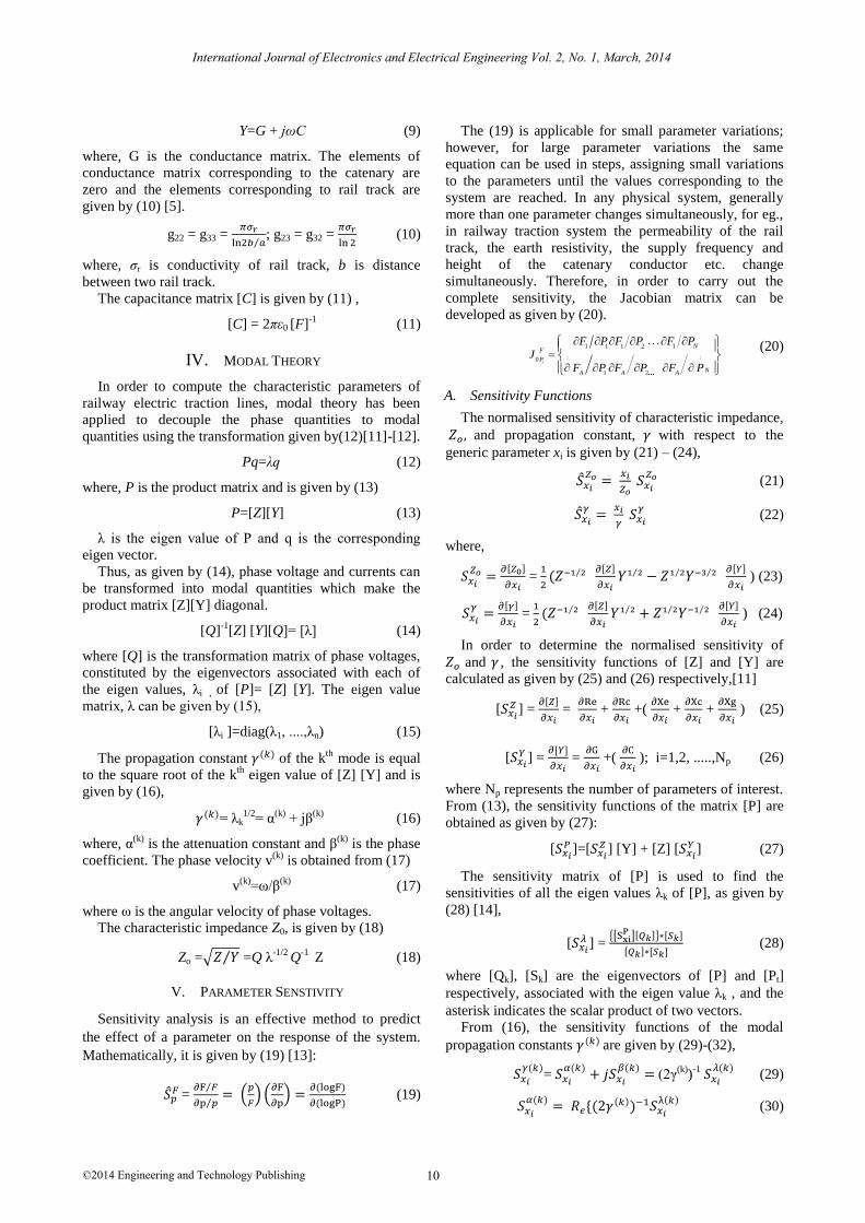
Fig. 3-Fig. 6 shows the variation of characteristic
impedance of contact wire and rail track conductor
respectively with respect to frequency for two frequency
ranges. It is noted that characteristic impedance of contact
wire decreases wrt the frequency up to around 170 kHz
and then starts increasing at higher frequencies whereas
the characteristic impedance of rail track conductor
increases exponentially with the frequency up to nearly
400 kHz and then it becomes approximately constant at
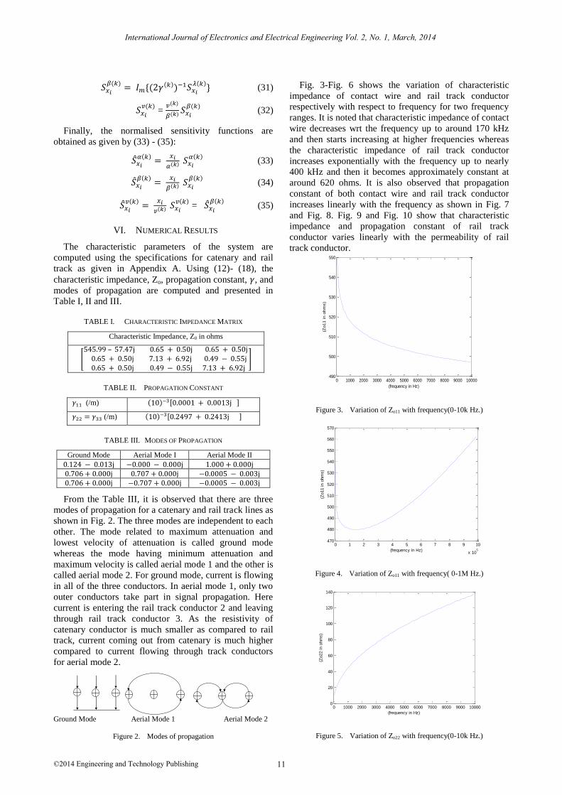
around 620 ohms. It is also observed that propagation
constant of both contact wire and rail track conductor
increases linearly with the frequency as shown in Fig. 7
and Fig. 8. Fig. 9 and Fig. 10 show that characteristic
impedance and propagation constant of rail track
conductor varies linearly with the permeability of rail
track conductor.
Figure 3. Variation of Zo11 with frequency(0-10k Hz.)
Figure 4. Variation of Zo11 with frequency( 0-1M Hz.)
Figure 5. Variation of Zo22 with frequency(0-10k Hz.)
0 1000 2000 3000 4000 5000 6000 7000 8000 9000 10000490
500
510
520
530
540
550
(frequency in Hz)
(Zo11 in o
hm
s)
0 1 2 3 4 5 6 7 8 9 10
x 105
470
480
490
500
510
520
530
540
550
560
570
(frequency in Hz)
(Zo11 in o
hm
s)
0 1000 2000 3000 4000 5000 6000 7000 8000 9000 100000
20
40
60
80
100
120
140
(frequency in Hz)
(Zo22 in o
hm
s)
Characteristic Impedance, Z0 in ohms
[
]
11
International Journal of Electronics and Electrical Engineering Vol. 2, No. 1, March, 2014
©2014 Engineering and Technology Publishing
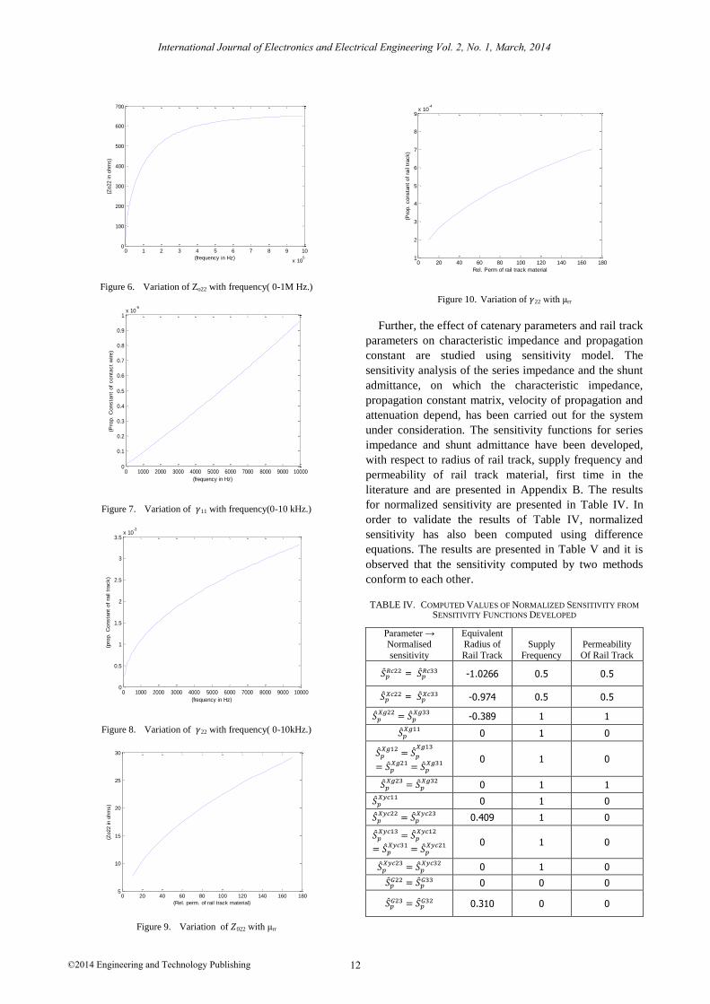
Figure 6. Variation of Zo22 with frequency( 0-1M Hz.)
Figure 7. Variation of 11 with frequency(0-10 kHz.)
Figure 8. Variation of 22 with frequency( 0-10kHz.)
Figure 9. Variation of 022 with μrr
Figure 10. Variation of 22 with μrr
Further, the effect of catenary parameters and rail track
parameters on characteristic impedance and propagation
constant are studied using sensitivity model. The
sensitivity analysis of the series impedance and the shunt
admittance, on which the characteristic impedance,
propagation constant matrix, velocity of propagation and
attenuation depend, has been carried out for the system
under consideration. The sensitivity functions for series
impedance and shunt admittance have been developed,
with respect to radius of rail track, supply frequency and
permeability of rail track material, first time in the
literature and are presented in Appendix B. The results
for normalized sensitivity are presented in Table IV. In
order to validate the results of Table IV, normalized
sensitivity has also been computed using difference
equations. The results are presented in Table V and it is
observed that the sensitivity computed by two methods
conform to each other.
TABLE IV. COMPUTED VALUES OF NORMALIZED SENSITIVITY FROM
SENSITIVITY FUNCTIONS DEVELOPED
0 1 2 3 4 5 6 7 8 9 10
x 105
0
100
200
300
400
500
600
700
(frequency in Hz)
(Zo22 in o
hm
s)
0 1000 2000 3000 4000 5000 6000 7000 8000 9000 100000
0.1
0.2
0.3
0.4
0.5
0.6
0.7
0.8
0.9
1x 10
-5
(frequency in Hz)
(Pro
p.
Consta
nt
of
conta
ct
wire)
0 1000 2000 3000 4000 5000 6000 7000 8000 9000 100000
0.5
1
1.5
2
2.5
3
3.5x 10
-3
(frequency in Hz)
(pro
p.
Consta
nt
of
rail t
rack)
0 20 40 60 80 100 120 140 160 1805
10
15
20
25
30
(Rel. perm. of rail track material)
(Zo22 in o
hm
s)
0 20 40 60 80 100 120 140 160 1801
2
3
4
5
6
7
8
9x 10
-4
Rel. Perm of rail track material
(Pro
p.
consta
nt
of
rail
track)
Parameter → Normalised
sensitivity
Equivalent Radius of
Rail Track
Supply
Frequency
Permeability
Of Rail Track
=
-1.0266 0.5 0.5
=
-0.974 0.5 0.5
-0.389 1 1
0 1 0
0 1 0
0 1 1
0 1 0
0.409 1 0
0 1 0
0 1 0
0 0 0
0.310 0 0
12
International Journal of Electronics and Electrical Engineering Vol. 2, No. 1, March, 2014
©2014 Engineering and Technology Publishing
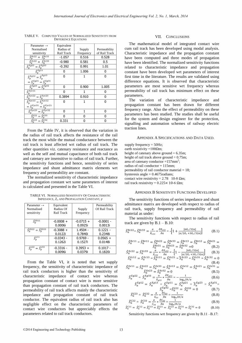
TABLE V. COMPUTED VALUES OF NORMALIZED SENSITIVITY FROM
DIFFERENCE EQUATIONS
From the Table IV, it is observed that the variation in
the radius of rail track affects the resistance of the rail
track the most while the mutual conductance between the
rail track is least affected wrt radius of rail track. The
other quantities viz. catenary resistance and reactance as
well as the self and mutual capacitance of both rail track
and catenary are insensitive to radius of rail track. Further,
the sensitivity functions and hence, sensitivity of series
impedance and shunt admittance matrix elements wrt
frequency and permeability are constant.
The normalized sensitivity of characteristic impedance
and propagation constant wrt same parameters of interest
is calculated and presented in the Table VI.
TABLE VI. NORMALIZED SENSITIVITY OF CHARACTERISTIC
IMPEDANCE, ZO AND PROPAGATION CONSTANT,
Parameter →
Normalised
sensitivity
Equivalent
Radius Of
Rail Track
Supply
Frequency
Permeability
Of Rail Track
-0.0008 +
0.0006i -0.0715 + 0.0925i
-0.0001 - 0.0013i
-0.3088 + 0.0122i
1.4504 - 0.7840i
0.1221 - 0.2348i
-0.0343 - 0.1262i
0.9769 - 0.1527i
0.0565 + 0.0148i
-0.3316 - 0.0096i
0.3953 + 0.0379i
0.1017 - 0.1820i
From the Table VI, it is noted that wrt supply
frequency, the sensitivity of characteristic impedance of
rail track conductors is higher than the sensitivity of
characteristic impedance of contact wire whereas
propagation constant of contact wire is more sensitive
than propagation constant of rail track conductors. The
permeability of rail track affects mainly the characteristic
impedance and propagation constant of rail track
conductor. The equivalent radius of rail track also has
negligible effect on the characteristic parameters of
contact wire conductors but appreciably effects the
parameters related to rail track conductors.
VII. CONCLUSIONS
The mathematical model of integrated contact wire
cum rail track has been developed using modal analysis.
Characteristic impedance and the propagation constant
have been computed and three modes of propagation
have been identified. The normalized sensitivity functions
related to characteristic impedance and propagation
constant have been developed wrt parameters of interest
first time in the literature. The results are validated using
difference equations. It is observed that characteristic
parameters are most sensitive wrt frequency whereas
permeability of rail track has minimum effect on these
parameters.
The variation of characteristic impedance and
propagation constant has been drawn for different
frequency range. Also the effect of permeability on these
parameters has been studied. The studies shall be useful
for the system and design engineer for the protection,
signalling and automation schemes of railway electric
traction lines.
APPENDIX A SPECIFICATIONS AND DATA USED.
supply frequency = 50Hz;
earth resistivity =100Ωm;
height of catenary above ground = 6.35m;
height of rail track above ground = 0.75m;
area of catenary conductor =157mm2;
radius of rail conductor = 115mm;
permeability of rail conductor material = 18;
hysteresis angle = 0.4675radians;
contact wire resistivity = 2.78 10-8 Ωm;
rail track resistivity = 0.225 -6 Ωm;
APPENDIX B SENSITIVITY FUNCTIONS DEVELOPED
The sensitivity functions of series impedance and shunt
admittance matrix are developed with respect to radius of
rail track, supply frequency and permeability of rail
material as under:
The sensitivity functions with respect to radius of rail
track are given by B.1 – B.10:
=
= -[
[ ⁄ ]
[ ⁄ ⁄ ]] (B.1)
=
0 (B.2)
= -[
[ ⁄ ]
[ ⁄ ⁄ ]] (B.3)
=
= =
= 0
(B.4)
0 (B.5)
=
=
⁄ (B.6)
=
=
=
=
=
0 (B.7)
=
=
⁄ (B.8)
=
=
⁄ (B.9)
(B.10)
Sensitivity functions wrt frequency are given by B.11 –B.17:
Parameter →
Normalised
sensitivity
Equivalent
Radius of
Rail Track
Supply
Frequency
Permeability
of Rail Track
=
-1.057 0.516 0.528
=
-0.980 0.581 0.5
-0.392 0.991 1.01
0 1.006 0
0 1 0
0 0.900 1.005
0 1 0
0.3894 0.910 0
0 1 0
0 1 0
0 0 0
0.331 0 0
13
International Journal of Electronics and Electrical Engineering Vol. 2, No. 1, March, 2014
©2014 Engineering and Technology Publishing
=
[ ⁄ ]
[ ⁄⁄ ] (B.11)
(B.12)
= [
] (B.13)
+
(log
)
+
θij
-
+
√
(B.13.1)
;
;
=
;
(B.13.2)
;
=
;
(B.13.2)
= [
] (B.14)
= (log
)
-
θij
+
√
-
+
√
-
(B.14.1)
;
(B.14.2)
=
[ ⁄ ]
[ ⁄⁄ ] (B.15)
(B.16)
(B.17)
Sensitivity functions with respect to permeability of rail track
are given by B.18 – B.25:
=
[ ⁄ ]
[ ⁄⁄ ] (B.18)
(B.19)
0 (B.20)
0 (B.21)
=
[ ⁄ ]
[ ⁄⁄ ] (B.22)
(B.23)
(B.24)
(B.25)
REFERENCES
[1] R. J. Hill and D. C. Carpenter, “Rail track distributed transmission
line impedance and admittance: Theoretical modeling and
experimental results,” IEEE Trans. Veh. Technol., vol. 42, no. 2, pp. 225-241, May 1993.
[2] A. Mariscotti, “Distribution of the traction return current in AC
and DC electric railway systems,” IEEE Trans. Power Del., vol. 18, no. 4, pp. 1422-1432, Oct. 2003.
[3] A. Mariscoti, M. Rusceli, and M. Vanti, “Modeling of
audiofrequency track circuits for validation, tuning, and conducted interference prediction,” IEEE Trans. Intell. Transp. Syst., vol. 11,
no. 1, pp. 52-60, Mar. 2010.
[4] R. Cella et al., “Measurement of AT electric railway system currents at power-supply frequency and validation of a
multiconductor transmission-line model,” IEEE Trans. Power Del.,
vol. 21, no. 3, pp. 1721-1726, July 2006. [5] R. J. Hill, S. Brillante, and P. J. Leonard, “Railway track
transmission line parameters from finite element field modelling:
Shunt admittance,” Proc. IEE- Electr. Power Appl., vol. 147, no. 3, pp. 227-238, May 2000.
[6] A. Mariscotti and P. Pozzobon, “Determination of the electrical
parameters of railway traction lines: calculation, measurement, and reference data,” IEEE Trans. Power Del., vol. 19, no. 4, pp.
1538-1546, Oct. 2004.
[7] A. Mariscoti, “Induced voltage calculation in electric traction systems: Simplified methods, screening factors, and accuracy,”
IEEE Trans. Intell. Transp. Syst., vol. 12, no. 1, pp. 52-60, Mar.
2011. [8] R. H. Galloway, W. Shorrocks, and L. M. Wedepohl, “Calculation
of electrical parameters for short and long polyphase transmission
lines,” Proc. IEE, vol. 111, pp. 2058-2059, 1969. [9] R. J. Hill and D. C. Carpenter, “Determination of rail internal
impedance for electric railway traction system simulation,” Proc.
IEE, vol. 138, no. 6, pp. 311-321, Nov. 1991. [10] J. R. Carson, “Wave propagation in overhead wires with ground
return,” Bell Syst.Tech.J., vol. 5, pp. 539-554, Oct.1926.
[11] P. Mahajan, R. Garg, and P. Kumar. (2011, Jan.) Sensitivity analysis of railway electric traction system. IICPE 2010. [Online].
Available: IEEE Xplore
[12] L. M. Wedepohl, “Application of matrix methods to the solution of travelling wave phenomenon in poly phase systems,” Proc. IEE,
vol. 10, no. 13, pp. 2200-2212, Dec. 1963.
[13] C. S. Indulkar, P. Kumar, and D. P. Kothari, “Sensitivity analysis of modal quantities for underground cables,” Proc. IEE, vol. 128,
no. 4, pp. 229-234, July 1981.
[14] C. S. Indulkar, P. Kumar, and D.P. Kothari, “Sensitivity analysis of multi conductor transmission line,” Proc. IEEE, vol. 70, no. 3,
pp. 299–300, Mar. 1982.
Rachana Garg received the B.E. and M.E. degree in 1986 and 1989 respectively from NIT, Bhopal. She has obtained her Ph.D in Electrical
Engg. from Delhi University in 2009. Presently, she is working as
Associate Prof. in Delhi Technological University, Delhi. Her area of interest is modeling of transmission lines, power system operation and
control.
Priya Mahajan received the B.E. and M.E. degree in 1996 and 1998
from Thapar Institute of Engg. & Tech. Patiala and Punjab Engg.
College, Chandigarh respectively. Presently she is pursuing the Ph.D degree in electrical engineering from Delhi University, Delhi. She is
working as Assistant Prof. in Delhi Technological University, Delhi
since last 13 years. Her area of interest includes power system and railway traction system.
Parmod Kumar received the B.E., M.E., and Ph.D. degrees in 1972, 1975, and 1982, respectively. After post-graduation in measurement and
instrumentation, he joined M.P. Electricity Board, M.P., India, as an
Assistant Engineer and commissioned telemetry and SCADA instruments at substations, power stations, and the central control room.
In 1983, he joined the Central Electricity Authority as a Dynamic
System Engineer and designed and configured the load dispatch centers for electric utilities. Subsequently, he served on various capacities to
Indian Railway Construction Company, ERCON, ESPL, ESTC, and
then entered academic life in 1991. His area of interest is smart and intelligent system design, operation, and control.
14
International Journal of Electronics and Electrical Engineering Vol. 2, No. 1, March, 2014
©2014 Engineering and Technology Publishing