Embed Size (px)
Citation preview
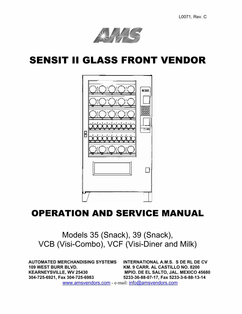
L0071, Rev. C
SENSIT II GLASS FRONT VENDOR
OPERATION AND SERVICE MANUAL
Models 35 (Snack), 39 (Snack), VCB (Visi-Combo), VCF (Visi-Diner and Milk)
AUTOMATED MERCHANDISING SYSTEMS 109 WEST BURR BLVD. KEARNEYSVILLE, WV 25430 304-725-6921, Fax 304-725-6983
INTERNATIONAL A.M.S. S DE RL DE CV KM. 9 CARR. AL CASTILLO NO. 8200 MPIO. DE EL SALTO, JAL. MEXICO 45680 5233-36-88-07-17, Fax 5233-3-6-88-13-14
www.amsvendors.com - e-mail: [email protected]


AMS SENSIT II GLASS FRONT VENDOR L0071, Rev. C
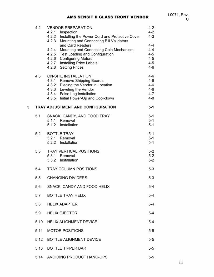
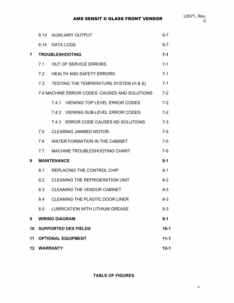
TABLE OF CONTENTS
TABLE OF FIGURES
1 INTRODUCTION 1-1 1.1 SENSIT II SYSTEM 1-1 1.1.1 Guaranteed Delivery 1-1 1.1.2 Instant Refund 1-1 1.1.3 Automatic Helix Adjustment 1-1 1.1.4 Additional Benefits 1-1 1.2 MODEL IDENTIFICATION 1-2 1.2.1 Model Number Breakdown 1-2 1.2.2 Serial Number and Date Code Breakdown 1-2 1.3 SPECIFICATIONS 1-3 1.3.1 Operating Environment 1-3 1.3.2 Dimensions: AMS35 1-3 1.3.3 Dimensions: AMS39 1-3 1.3.4 Dimensions: VCB (Visi-Combo) 1-3 1.3.5 Dimensions: VCF (Visi-Diner and Milk) 1-3 1.3.6 Power Requirements 1-3 1.3.7 Refrigeration Specification 1-3 1.3.8 Coin Mechanisms and Bill Validators 1-3 1.4 STANDARD HELIX CONFIGURATIONS 1-6 1.4.1 AMS35 Models 1-6 1.4.2 AMS39 Models 1-7 1.4.3 AMS VCB Visi-Combo 1-8 1.4.4 AMS VCF Visi-Diner 1-9 1.4.5 AMS Milk 1-10 2 SAFETY 2-1 2.1 COMMITMENT TO SAFETY 2-1 2.2 SAFETY PRECAUTIONS 2-1 2.2.1 High Voltage Contact 2-1 2.2.2 Improper Grounding 2-2 2.2.3 Fan Contact 2-2 2.2.4 Helix Motion and Jamming 2-2 2.2.5 Refrigerant Release 2-2 2.2.6 Vendor Tipping 2-3 2.2.7 Other Improper Conditions 2-3 3 VENDOR SYSTEMS AND COMPONENTS 3-1 3.1 SENSIT II SYSTEM THEORY OF OPERATION 3-1 3.2 CONTROL BOARD 3-1 3.2.1 Control Chip 3-2
i
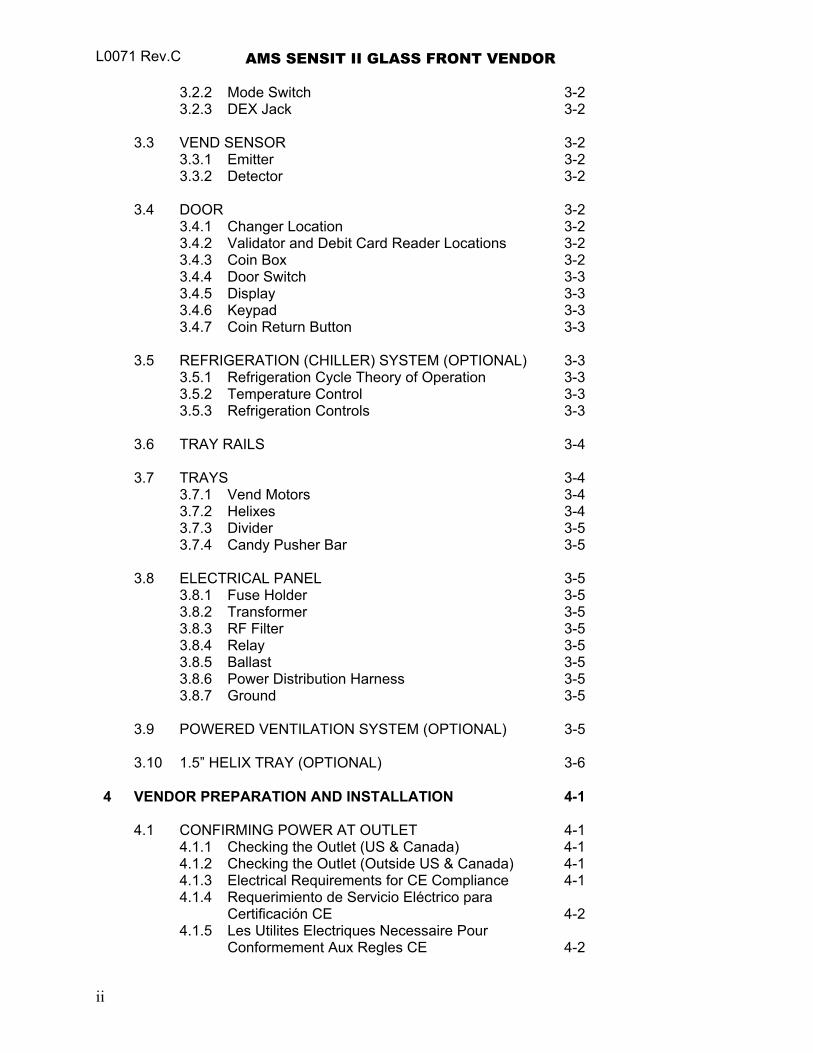
L0071 Rev.C AMS SENSIT II GLASS FRONT VENDOR 3.2.2 Mode Switch 3-2 3.2.3 DEX Jack 3-2 3.3 VEND SENSOR 3-2 3.3.1 Emitter 3-2 3.3.2 Detector 3-2 3.4 DOOR 3-2 3.4.1 Changer Location 3-2 3.4.2 Validator and Debit Card Reader Locations 3-2 3.4.3 Coin Box 3-2 3.4.4 Door Switch 3-3 3.4.5 Display 3-3 3.4.6 Keypad 3-3 3.4.7 Coin Return Button 3-3 3.5 REFRIGERATION (CHILLER) SYSTEM (OPTIONAL) 3-3 3.5.1 Refrigeration Cycle Theory of Operation 3-3 3.5.2 Temperature Control 3-3 3.5.3 Refrigeration Controls 3-3 3.6 TRAY RAILS 3-4 3.7 TRAYS 3-4 3.7.1 Vend Motors 3-4 3.7.2 Helixes 3-4 3.7.3 Divider 3-5 3.7.4 Candy Pusher Bar 3-5 3.8 ELECTRICAL PANEL 3-5 3.8.1 Fuse Holder 3-5 3.8.2 Transformer 3-5 3.8.3 RF Filter 3-5 3.8.4 Relay 3-5 3.8.5 Ballast 3-5 3.8.6 Power Distribution Harness 3-5 3.8.7 Ground 3-5 3.9 POWERED VENTILATION SYSTEM (OPTIONAL) 3-5 3.10 1.5” HELIX TRAY (OPTIONAL) 3-6 4 VENDOR PREPARATION AND INSTALLATION 4-1 4.1 CONFIRMING POWER AT OUTLET 4-1 4.1.1 Checking the Outlet (US & Canada) 4-1 4.1.2 Checking the Outlet (Outside US & Canada) 4-1 4.1.3 Electrical Requirements for CE Compliance 4-1 4.1.4 Requerimiento de Servicio Eléctrico para Certificación CE 4-2 4.1.5 Les Utilites Electriques Necessaire Pour Conformement Aux Regles CE 4-2
ii
AMS SENSIT II GLASS FRONT VENDOR L0071, Rev. C
4.2 VENDOR PREPARATION 4-2 4.2.1 Inspection 4-2 4.2.2 Installing the Power Cord and Protective Cover 4-3
4.2.3 Mounting and Connecting Bill Validators and Card Readers 4-4 4.2.4 Mounting and Connecting Coin Mechanism 4-4 4.2.5 Test Loading and Configuration 4-5 4.2.6 Configuring Motors 4-5 4.2.7 Installing Price Labels 4-5 4.2.8 Setting Prices 4-6 4.3 ON-SITE INSTALLATION 4-6 4.3.1 Remove Shipping Boards 4-6 4.3.2 Placing the Vendor in Location 4-6 4.3.3 Leveling the Vendor 4-6 4.3.4 False Leg Installation 4-7 4.3.5 Initial Power-Up and Cool-down 4-8 5 TRAY ADJUSTMENT AND CONFIGURATION 5-1
5.1 SNACK, CANDY, AND FOOD TRAY 5-1 5.1.1 Removal 5-1 5.1.2 Installation 5-1 5.2 BOTTLE TRAY 5-1 5.2.1 Removal 5-1 5.2.2 Installation 5-1 5.3 TRAY VERTICAL POSITIONS 5-2 5.3.1 Removal 5-2 5.3.2 Installation 5-2 5.4 TRAY COLUMN POSITIONS 5-3 5.5 CHANGING DIVIDERS 5-3 5.6 SNACK, CANDY AND FOOD HELIX 5-4 5.7 BOTTLE TRAY HELIX 5-4 5.8 HELIX ADAPTER 5-4 5.9 HELIX EJECTOR 5-4 5.10 HELIX ALIGNMENT DEVICE 5-4 5.11 MOTOR POSITIONS 5-5 5.12 BOTTLE ALIGNMENT DEVICE 5-5 5.13 BOTTLE TIPPER BAR 5-5
iii
5.14 AVOIDING PRODUCT HANG-UPS 5-5
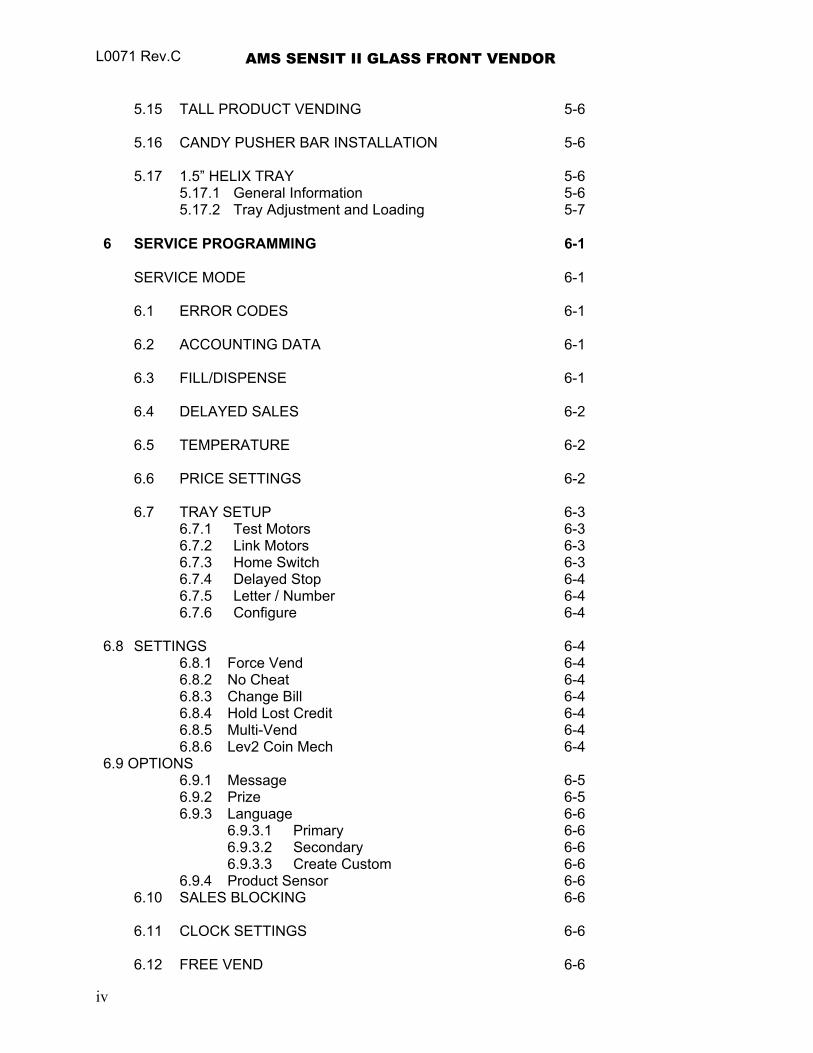
L0071 Rev.C AMS SENSIT II GLASS FRONT VENDOR 5.15 TALL PRODUCT VENDING 5-6 5.16 CANDY PUSHER BAR INSTALLATION 5-6 5.17 1.5” HELIX TRAY 5-6 5.17.1 General Information 5-6 5.17.2 Tray Adjustment and Loading 5-7 6 SERVICE PROGRAMMING 6-1 SERVICE MODE 6-1 6.1 ERROR CODES 6-1 6.2 ACCOUNTING DATA 6-1 6.3 FILL/DISPENSE 6-1 6.4 DELAYED SALES 6-2 6.5 TEMPERATURE 6-2 6.6 PRICE SETTINGS 6-2 6.7 TRAY SETUP 6-3 6.7.1 Test Motors 6-3 6.7.2 Link Motors 6-3 6.7.3 Home Switch 6-3 6.7.4 Delayed Stop 6-4 6.7.5 Letter / Number 6-4 6.7.6 Configure 6-4 6.8 SETTINGS 6-4
6.8.1 Force Vend 6-4 6.8.2 No Cheat 6-4 6.8.3 Change Bill 6-4 6.8.4 Hold Lost Credit 6-4 6.8.5 Multi-Vend 6-4 6.8.6 Lev2 Coin Mech 6-4
6.9 OPTIONS 6.9.1 Message 6-5 6.9.2 Prize 6-5 6.9.3 Language 6-6
6.9.3.1 Primary 6-6 6.9.3.2 Secondary 6-6 6.9.3.3 Create Custom 6-6
6.9.4 Product Sensor 6-6 6.10 SALES BLOCKING 6-6 6.11 CLOCK SETTINGS 6-6 6.12 FREE VEND 6-6
iv
AMS SENSIT II GLASS FRONT VENDOR L0071, Rev. C
6.13 AUXILIARY OUTPUT 6-7 6.14 DATA LOGS 6-7 7 TROUBLESHOOTING 7-1 7.1 OUT OF SERVICE ERRORS 7-1 7.2 HEALTH AND SAFETY ERRORS 7-1 7.3 TESTING THE TEMPERATURE SYSTEM (H & S) 7-1 7.4 MACHINE ERROR CODES: CAUSES AND SOLUTIONS 7-2 7.4.1 VIEWING TOP LEVEL ERROR CODES 7-2 7.4.2 VIEWING SUB-LEVEL ERROR CODES 7-2 7.4.3 ERROR CODE CAUSES ND SOLUTIONS 7-3 7.5 CLEARING JAMMED MOTOR 7-5 7.6 WATER FORMATION IN THE CABINET 7-5 7.7 MACHINE TROUBLESHOOTING CHART 7-6 8 MAINTENANCE 8-1 8.1 REPLACING THE CONTROL CHIP 8-1 8.2 CLEANING THE REFRIGERATION UNIT 8-2 8.3 CLEANING THE VENDOR CABINET 8-3 8.4 CLEANING THE PLASTIC DOOR LINER 8-3 8.5 LUBRICATION WITH LITHIUM GREASE 8-3 9 WIRING DIAGRAM 9-1 10 SUPPORTED DEX FIELDS 10-1 11 OPTIONAL EQUIPMENT 11-1 12 WARRANTY 12-1
TABLE OF FIGURES
v
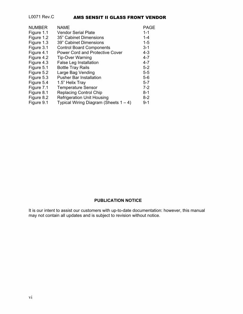
L0071 Rev.C AMS SENSIT II GLASS FRONT VENDOR NUMBER NAME PAGE Figure 1.1 Vendor Serial Plate 1-1 Figure 1.2 35” Cabinet Dimensions 1-4 Figure 1.3 39” Cabinet Dimensions 1-5 Figure 3.1 Control Board Components 3-1 Figure 4.1 Power Cord and Protective Cover 4-3 Figure 4.2 Tip-Over Warning 4-7 Figure 4.3 False Leg Installation 4-7 Figure 5.1 Bottle Tray Rails 5-2 Figure 5.2 Large Bag Vending 5-5 Figure 5.3 Pusher Bar Installation 5-6 Figure 5.4 1.5” Helix Tray 5-7 Figure 7.1 Temperature Sensor 7-2 Figure 8.1 Replacing Control Chip 8-1 Figure 8.2 Refrigeration Unit Housing 8-2 Figure 9.1 Typical Wiring Diagram (Sheets 1 – 4) 9-1
PUBLICATION NOTICE It is our intent to assist our customers with up-to-date documentation: however, this manual may not contain all updates and is subject to revision without notice.
vi
AMS SENSIT II GLASS FRONT VENDOR L0071, Rev. C
1.0 INTRODUCTION
Congratulations on the purchase of your new AMS Sensit II vendor. All Sensit II models, including Snack, Visi-Combo, Visi-Diner and Milk, are versatile, high-capacity vending machines. AMS machines are designed, tested, and built to provide years of reliable, low-maintenance service in an indoor environment. A fully insulated cabinet, DEX data capability, and flexible product configuration are just some of the many standard features built into every AMS merchandiser.
1.1 SENSIT II SYSTEM Your vendor is equipped with the Sensit II system. The Sensit II system is a
patented vend-sensing system that detects when products fall into the delivery bin. Basically, a plane of infra-red light beams is created across the top of the delivery bin, and the Sensit II system can detect when any part of the light has been blocked by a passing product. Using this technology, the vendor “knows” when your customer gets the product. The Sensit II system has several important benefits:
1.1.1 Guaranteed Delivery If, after one revolution, the product hangs up or an opening was missed in
loading, the helix will rotate three separate half-revolutions to make sure the product is delivered. No more hitting or shaking the vendor to get products that did not fall!
1.1.2 Instant Refund
If the customer does not receive a product, he can receive a full refund by pressing the coin return, or he can select another product. No more refund requests!
1.1.3 Automatic Helix Adjustment
With the Sensit II system, the helix stops as soon as the product falls. It is no longer necessary to adjust the home position of the helix for each different package. In fact, different packages can be loaded in the same column. No more double vending!
1.1.4 Additional Benefits:
1. Opening the delivery bin door will not affect the Sensit II system. The sensors are located above the delivery bin and will not be blocked by the door. Product that falls while the door is open will still pass through the beam.
2. Shining a light at the detector will not allow vandals to receive free product. Any tampering which changes the precise amount of light normally received will be treated as a successful vend, resulting in the vandal losing his money.
3. Disabling or blocking the sensor will not allow vandals to receive free product. The Sensit II system must be receiving the normal amount of light before the vendor will dispense any product.
4. Opening the door of a cold vendor will cause some condensation to form inside. The Sensit II system will not allow vending until this fogging clears, normally within a few minutes of closing the door.
1-1
L0071 Rev.C AMS SENSIT II GLASS FRONT VENDOR 1.2 MODEL IDENTIFICATION
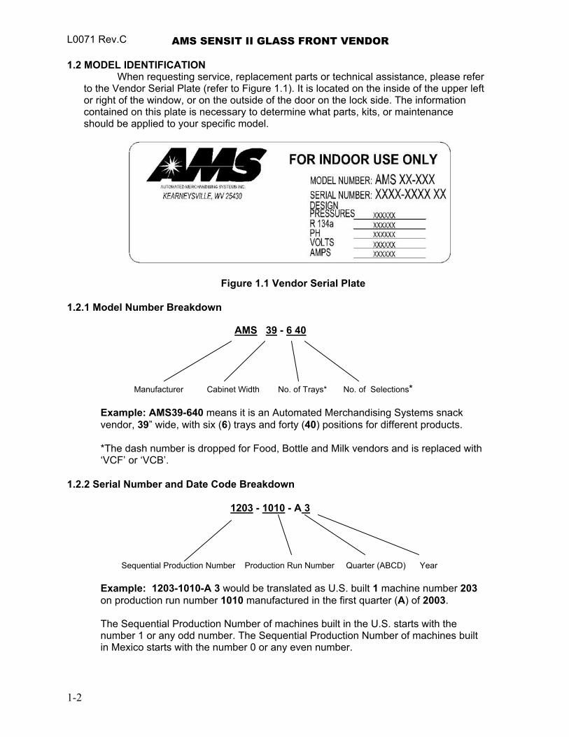
When requesting service, replacement parts or technical assistance, please refer to the Vendor Serial Plate (refer to Figure 1.1). It is located on the inside of the upper left or right of the window, or on the outside of the door on the lock side. The information contained on this plate is necessary to determine what parts, kits, or maintenance should be applied to your specific model.
Figure 1.1 Vendor Serial Plate 1.2.1 Model Number Breakdown
AMS 39 - 6 40
Manufacturer Cabinet Width No. of Trays* No. of Selections*
Example: AMS39-640 means it is an Automated Merchandising Systems snack vendor, 39” wide, with six (6) trays and forty (40) positions for different products.
*The dash number is dropped for Food, Bottle and Milk vendors and is replaced with ‘VCF’ or ‘VCB’.
1.2.2 Serial Number and Date Code Breakdown
1203 - 1010 - A 3
Sequential Production Number Production Run Number Quarter (ABCD) Year
Example: 1203-1010-A 3 would be translated as U.S. built 1 machine number 203 on production run number 1010 manufactured in the first quarter (A) of 2003. The Sequential Production Number of machines built in the U.S. starts with the number 1 or any odd number. The Sequential Production Number of machines built in Mexico starts with the number 0 or any even number.
1-2
AMS SENSIT II GLASS FRONT VENDOR L0071, Rev. C
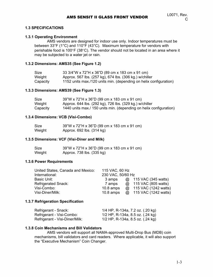
1.3 SPECIFICATIONS 1.3.1 Operating Environment
AMS vendors are designed for indoor use only. Indoor temperatures must be between 33°F (1°C) and 110°F (43°C). Maximum temperature for vendors with perishable food is 100°F (38°C). The vendor should not be located in an area where it may be subjected to a water jet or rain.
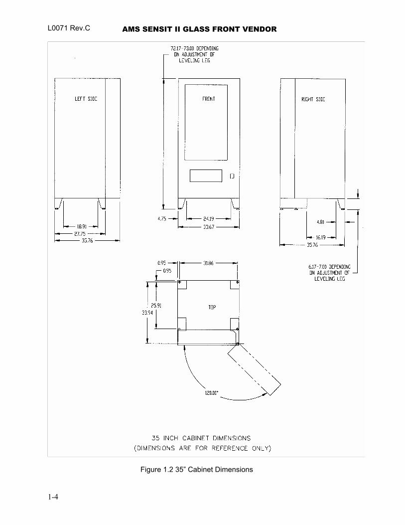
1.3.2 Dimensions: AMS35 (See Figure 1.2)
Size 33 3/4”W x 72”H x 36”D (89 cm x 183 cm x 91 cm) Weight Approx. 567 lbs. (257 kg), 674 lbs. (306 kg.) w/chiller Capacity 1152 units max./120 units min. (depending on helix configuration)
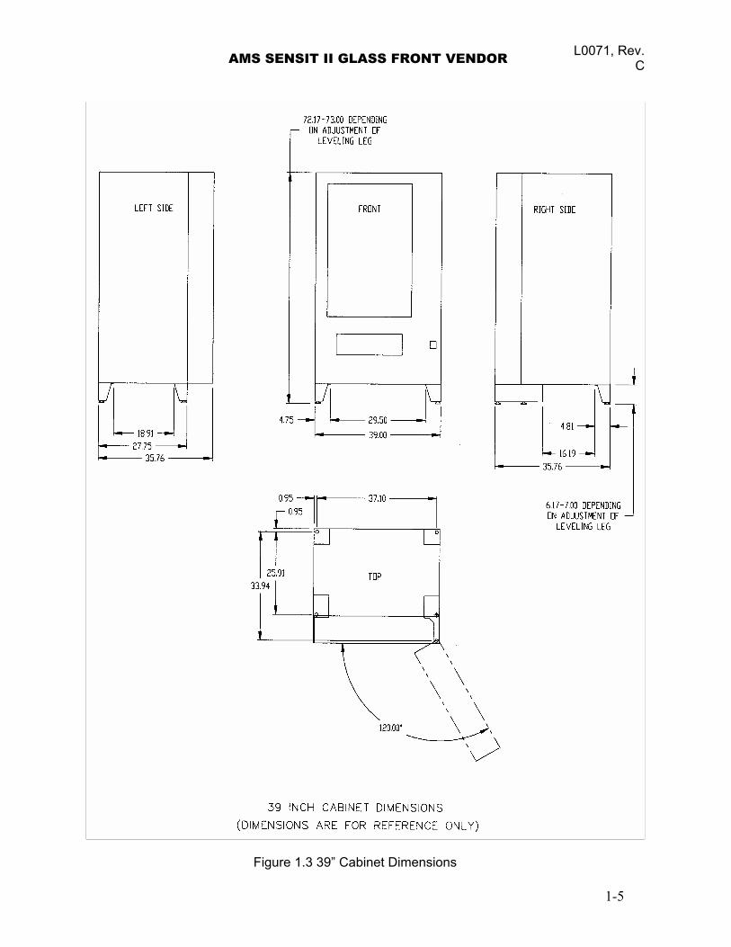
1.3.3 Dimensions: AMS39 (See Figure 1.3)
Size 39”W x 72”H x 36”D (99 cm x 183 cm x 91 cm) Weight Approx. 644 lbs. (292 kg), 726 lbs. (329 kg.) w/chiller Capacity 1440 units max./ 150 units min. (depending on helix configuration)
1.3.4 Dimensions: VCB (Visi-Combo)
Size 39”W x 72”H x 36”D (99 cm x 183 cm x 91 cm) Weight Approx. 692 lbs. (314 kg)
1.3.5 Dimensions: VCF (Visi-Diner and Milk)
Size 39”W x 72”H x 36”D (99 cm x 183 cm x 91 cm) Weight Approx. 738 lbs. (335 kg)
1.3.6 Power Requirements
United States, Canada and Mexico: 115 VAC, 60 Hz International: 230 VAC, 50/60 Hz Basic Unit: 3 amps @ 115 VAC (345 watts) Refrigerated Snack: 7 amps @ 115 VAC (805 watts) Visi-Combo: 10.8 amps @ 115 VAC (1242 watts) Visi-Diner/Milk: 10.8 amps @ 115 VAC (1242 watts)
1.3.7 Refrigeration Specification
Refrigerant - Snack: 1/4 HP, R-134a, 7.2 oz. (.20 kg) Refrigerant - Visi-Combo: 1/2 HP, R-134a, 8.5 oz. (.24 kg) Refrigerant - Visi-Diner/Milk: 1/2 HP, R-134a, 8.5 oz. (.24 kg)
1.3.8 Coin Mechanisms and Bill Validators
AMS vendors will support all NAMA-approved Multi-Drop Bus (MDB) coin mechanisms, bill validators and card readers. Where applicable, it will also support the “Executive Mechanism” Coin Changer.
1-3
L0071 Rev.C AMS SENSIT II GLASS FRONT VENDOR
Figure 1.2 35” Cabinet Dimensions
1-4
AMS SENSIT II GLASS FRONT VENDOR L0071, Rev. C
Figure 1.3 39” Cabinet Dimensions
1-5
L0071 Rev.C AMS SENSIT II GLASS FRONT VENDOR
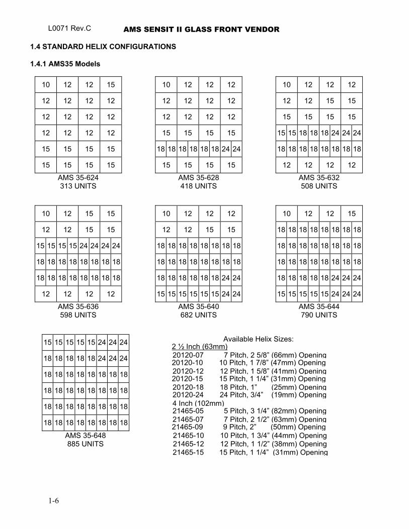
1.4 STANDARD HELIX CONFIGURATIONS 1.4.1 AMS35 Models
10 12 12 15 10 12 12 12 10 12 12 12
12 12 12 12 12 12 12 12 12 12 15 15
12 12 12 12 12 12 12 12 15 15 15 15
12 12 12 12 15 15 15 15 15 15 18 18 18 24 24 24
15 15 15 15 18 18 18 18 18 18 24 24 18 18 18 18 18 18 18 18
15 15 15 15 15 15 15 15 12 12 12 12
AMS 35-624 313 UNITS
AMS 35-628 418 UNITS
AMS 35-632 508 UNITS
10 12 15 15 10 12 12 12 10 12 12 15
12 12 15 15 12 12 15 15 18 18 18 18 18 18 18 18
15 15 15 15 24 24 24 24 18 18 18 18 18 18 18 18 18 18 18 18 18 18 18 18
18 18 18 18 18 18 18 18 18 18 18 18 18 18 18 18 18 18 18 18 18 18 18 18
18 18 18 18 18 18 18 18 18 18 18 18 18 18 24 24 18 18 18 18 18 24 24 24
12 12 12 12 15 15 15 15 15 15 24 24 15 15 15 15 15 24 24 24
AMS 35-636 598 UNITS
AMS 35-640 682 UNITS
AMS 35-644 790 UNITS
Available Helix Sizes: 15 15 15 15 15 24 24 24 2 ½ Inch (63mm) 20120-07 7 Pitch, 2 5/8” (66mm) Opening 18 18 18 18 18 24 24 24 20120-10 10 Pitch, 1 7/8” (47mm) Opening 20120-12 12 Pitch, 1 5/8” (41mm) Opening 18 18 18 18 18 18 18 18 20120-15 15 Pitch, 1 1/4” (31mm) Opening 20120-18 18 Pitch, 1” (25mm) Opening 18 18 18 18 18 18 18 18 20120-24 24 Pitch, 3/4” (19mm) Opening 4 Inch (102mm)18 18 18 18 18 18 18 18 21465-05 5 Pitch, 3 1/4” (82mm) Opening 21465-07 7 Pitch, 2 1/2” (63mm) Opening 18 18 18 18 18 18 18 18 21465-09 9 Pitch, 2” (50mm) Opening
21465-10 10 Pitch, 1 3/4” (44mm) Opening AMS 35-648 885 UNITS 21465-12 12 Pitch, 1 1/2” (38mm) Opening
21465-15 15 Pitch, 1 1/4” (31mm) Opening
1-6
AMS SENSIT II GLASS FRONT VENDOR L0071, Rev. C
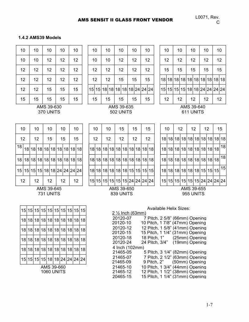
1.4.2 AMS39 Models
10 10 10 10 10 10 10 10 10 10 10 10 10 10 10
10 10 12 12 12 10 10 12 12 12 12 12 12 12 12
12 12 12 12 12 12 12 12 12 12 15 15 15 15 15
12 12 12 12 12 12 12 15 15 15 18 18 18 18 18 18 18 18 18 18
12 12 15 15 15 15 15 18 18 18 18 18 24 24 24 15 15 15 15 18 18 24 24 24 24
15 15 15 15 15 15 15 15 15 15 12 12 12 12 12
AMS 39-630 370 UNITS
AMS 39-635 502 UNITS
AMS 39-640 611 UNITS
10 10 10 10 10 10 10 15 15 15 10 12 12 12 15
12 12 15 15 15 12 12 12 12 12 18 18 18 18 18 18 18 18 18 18
18 18 18 18 18 18 18 18 18 18 18 18 18 18 18 18 18 18 18 18 18 18 18 18 18 18 18 18 18 18
18 18 18 18 18 18 18 18 18 18 18 18 18 18 18 18 18 18 18 18 18 18 18 18 18 18 18 18 18 18
15 15 15 15 18 18 24 24 24 24 18 18 18 18 18 18 15 15 15 15 18 18 18 18 18 18 15 15 15 15
12 12 12 12 12 15 15 15 15 15 15 24 24 24 24 15 15 15 15 15 15 24 24 24 24
AMS 39-645 731 UNITS
AMS 39-650 839 UNITS
AMS 39-655 955 UNITS
Available Helix Sizes: 15 15 15 15 15 15 15 15 15 15 2 ½ Inch (63mm) 20120-07 7 Pitch, 2 5/8” (66mm) Opening18 18 18 18 18 18 18 18 18 18 20120-10 10 Pitch, 1 7/8” (47mm) Opening 20120-12 12 Pitch, 1 5/8” (41mm) Opening18 18 18 18 18 18 18 18 18 18 20120-15 15 Pitch, 1 1/4” (31mm) Opening 20120-18 18 Pitch, 1” (25mm) Opening18 18 18 18 18 18 18 18 18 18 20120-24 24 Pitch, 3/4” (19mm) Opening 4 Inch (102mm)18 18 18 18 18 18 18 18 18 18 21465-05 5 Pitch, 3 1/4” (82mm) Opening 21465-07 7 Pitch, 2 1/2” (63mm) Opening15 15 15 15 18 18 24 24 24 24 21465-09 9 Pitch, 2” (50mm) Opening
AMS 39-660 21465-10 10 Pitch, 1 3/4” (44mm) Opening1060 UNITS 21465-12 12 Pitch, 1 1/2” (38mm) Opening
20465-15 15 Pitch, 1 1/4” (31mm) Opening
1-7
L0071 Rev.C AMS SENSIT II GLASS FRONT VENDOR
1.4.3 AMS VCB Visi-Combo
10 10 15 15 15
12 12 12 12 12
15 15 15 15 15 18 18 18 18 18
6 6 6 6 6 6 6 6
6 6 6 6 6 6 6 6
AMS 39-VISI-COMBO 386 UNITS
Available Helix Sizes:2 ½ Inch (63mm)
20120-07 7 Pitch, 2 5/8” (66mm) Opening20120-10 10 Pitch, 1 7/8” (47mm) Opening
20120-12 12 Pitch, 1 5/8” (41mm) Opening20120-15 15 Pitch, 1 1/4” (31mm) Opening
20120-18 18 Pitch, 1” (25mm) Opening 20120-24 24 Pitch, 3/4” (19mm) Opening 3 Inch (76mm) 21336
6 Pitch, 3 1/2” (88mm) Opening (Bottle / Milk Trays Only)
4 Inch (102mm) 21465-05 5 Pitch, 3 1/4” (82mm) Opening 21465-07 7 Pitch, 2 1/2” (63mm) Opening21465-09 9 Pitch, 2” (50mm) Opening
21465-10 10 Pitch, 1 3/4” (44mm) Opening 21465-12 12 Pitch, 1 1/2” (38mm) Opening 21165-15 15 Pitch, 1 1/4” (31mm) Opening
1-8
AMS SENSIT II GLASS FRONT VENDOR L0071, Rev. C
1.4.4 AMS VCF Visi-Diner
5 5 5 5 5
5 5 5 5 5
5 5 5 5 5
7 7 7 7 7
7 7 7 7 7
7 7 7 7 7
AMS 39-FOOD 180 UNITS
Available Helix Sizes:2 ½ Inch (63mm)
20120-07 7 Pitch, 2 5/8” (66mm) Opening20120-10 10 Pitch, 1 7/8” (47mm) Opening
20120-12 12 Pitch, 1 5/8” (41mm) Opening20120-15 15 Pitch, 1 1/4” (31mm) Opening
20120-18 18 Pitch, 1” (25mm) Opening 20120-24 24 Pitch, 3/4” (19mm) Opening 4 Inch (102mm) 21465-05 5 Pitch, 3 1/4” (82mm) Opening 21465-07 7 Pitch, 2 1/2” (63mm) Opening21465-09 9 Pitch, 2” (50mm) Opening
21465-10 10 Pitch, 1 3/4” (44mm) Opening 21465-12 12 Pitch, 1 1/2” (38mm) Opening 21465-15 15 Pitch, 1 1/4” (31mm) Opening
1-9
L0071 Rev.C AMS SENSIT II GLASS FRONT VENDOR
1.4.5 AMS Milk
6 6 6 6 6 6 6 6
6 6 6 6 6 6 6 6 6 6 6 6 6 6 6 6
6 6 6 6 6 6 6 6 6 6 6 6 6 6 6 6
6 6 6 6 6 6 6 6 6 6 6 6 6 6 6 6
6 6 6 6 6 6 6 6 6 6 6 6 6 6 6 6
6 6 6 6 6 6 6 6 6 6 6 6 6 6 6 6
6 6 6 6 6 6 6 6 6 6 6 6 6 6 6 6
AMS 39-Milk 240 UNITS
AMS 39-Milk 288 UNITS
Available Helix Sizes:
3 Inch (76mm) 21336 6 Pitch, 3 1/2” (88mm) Opening (Bottle / Milk Trays Only)
1-10
AMS SENSIT II GLASS FRONT VENDOR L0071, Rev. C
2.0 SAFETY 2.1 COMMITMENT TO SAFETY
Automated Merchandising Systems Inc. is committed to designing and producing a safe product. As with all electrical or mechanical pieces of equipment, potential hazards exist. It is the intent of Automated Merchandising Systems, through this manual and service technician training, to alert individuals who will be servicing our equipment to these potential hazards, and to provide basic safety guidelines.
To reduce the risk of serious injury or death, please read and follow all warnings in this manual. It is important that we point out that these warnings are not comprehensive. Automated Merchandising Systems can not possibly anticipate all of the ways that service may be conducted, nor all of the possible safety hazards that may result from service. Therefore at all times we urge you to beware of hazards such as electrical shock, mechanical entrapment, and tipping a vendor during movement.
Automated Merchandising Systems strongly recommends a commitment to safety on the part of all servicing personnel or organizations. Only personnel properly trained in vendor servicing should attempt any service to the internal components of the vendor. It is important to point out that Automated Merchandising Systems has no control over the vendor once it leaves our factory. Maintaining the vendor in a safe condition is the sole responsibility of the owner.
If you have questions concerning safety or service, or would like more information, please contact the Automated Merchandising Systems Service Department at 304-725-6921 or e-mail [email protected].
2.2 SAFETY PRECAUTIONS
Below are listed safety precautions and safe practices to follow to avoid injury from selected hazards. This list can not possibly cover all hazards, therefore please remember to THINK SAFETY FIRST.
2.2.1 High Voltage Contact
All vendors are designed to operate on a specific voltage, either single phase 115VAC 60Hz or 220-240VAC 50-60Hz, depending on the country. The voltage is specified on the serial plate (refer to Model Identification 1.2). High voltage areas include the electrical panel, the refrigeration unit and fans, and the fluorescent lamp. It is important to understand that contact with the high voltage wiring can result in injury or death. 1. Always test the outlet for proper voltage, polarity and grounding before plugging
in the vendor. 2. Always disconnect power to the vendor before servicing. Allow only fully trained
service technicians to service the vendor if service must be performed with the power on.
3. Always keep electrical connections dry. Do not place the vendor in or near standing water.
4. Never use a worn or damaged power cord.
2-11
L0071 Rev.C AMS SENSIT II GLASS FRONT VENDOR 2.2.2 Improper Grounding
Some electrical components have a green or green/yellow ground wire attached to a grounding point in the vendor. If it becomes necessary to remove a ground wire during service, note how the wire is attached, including the locations of any washers. After servicing, make sure that the wires and washers are replaced exactly as they were. Note that the vendor will work normally without the ground wires, but there will be a potential shock hazard from ungrounded components.
1. Always test the outlet for proper grounding before plugging in the vendor. 2. Always reconnect ground wires after servicing.
2.2.3 Fan Contact
Some vendors are equipped with electric fans, which can start automatically. These fans are guarded to prevent accidental contact. However, removal of guards or other components can leave fan blades exposed and create a physical hazard. 1. Always disconnect power to the vendor before servicing. 2. Always keep protective covers in place. 3. Always wear hand and eye protection when servicing the vendor. 4. Always keep hands, hair, loose clothing and tools away from fan blades. 5. Never insert hands or tools into concealed areas. 6. Always replace protective covers after service.
2.2.4 Helix Motion and Jamming
Energized vend motors can turn a helix with considerable torque, creating a possible entrapment hazard. Also, turning helixes may eject tools or other objects left on trays. A helix that is jammed or caught can store energy as it binds, which can cause it to twist or spring outward suddenly even if power is disconnected. Use caution when freeing a jammed helix. 1. Always disconnect power to the vendor or control board before servicing the
vend motors. 2. Always check for proper fit when loading products in helixes to avoid jamming. 3. Always restrain the helix before freeing a jammed or caught helix. 4. Always wear hand and eye protection when servicing the vendor. 5. Always keep hands, hair, loose clothing and tools away from moving parts.
2.2.5 Refrigerant Release The refrigeration system is pressurized and sealed at the factory. Puncturing
or cutting any component in the system will cause refrigerant gas and liquid to be propelled out of the system, creating an immediate physical hazard. Use caution to avoid accidentally opening the refrigerant system.
It should also be noted that releasing refrigerant to the atmosphere is a federal crime and is punishable by law. Any service work requiring the system to be opened must be performed by a licensed technician using certified equipment. Unauthorized service to the sealed refrigerant system may void the warranty.
1. Never puncture or cut any component in the refrigeration system. 2. Always use licensed service technicians to service the refrigeration system. 3. Always wear hand and eye protection when servicing the vendor.
2-2

AMS SENSIT II GLASS FRONT VENDOR L0071, Rev. C
2.2.6 Vendor Tipping The empty weight of the vendor is approximately 576 to 800 pounds. A falling
vendor can cause serious injury or death. Caution should always be taken to avoid dropping or tipping a vendor. 1. Never rock or tip the vendor. 2. Never place the vendor in an inclined position, such as on a ramp or with all the
legs not on the same horizontal surface. 3. Never place the vendor in a moving environment such as on a ship without properly
securing it in place. 4. Never place the vendor in a location where it may be struck by a vehicle. 5. Never transport an unsecured vendor. 6. Never attempt to lift or move the vendor by hand. Always use equipment with the
proper load rating. Note that the Specification weight listed is empty weight.
2.2.7 Other Improper Conditions Hazardous conditions can be created by improper use or service of the
vendor.
1. Always reinstall any parts removed during service to their original locations. 2. Never make unauthorized modifications to any part of the vendor. 3. Always replace components that are worn, broken, or otherwise unfit for use. 4. Never use unauthorized parts, or use parts for anything other than their intended
application.
2-31

L0071 Rev.C AMS SENSIT II GLASS FRONT VENDOR
2-4
AMS SENSIT II GLASS FRONT VENDOR L0071, Rev. C
3.0 VENDOR SYSTEMS AND COMPONENTS
3.1 SENSIT II SYSTEM THEORY OF OPERATION
1. The Sensit II system is comprised of three elements; the emitter, the detector, and the control logic. The emitter is a circuit board with infra-red emitting LED’s located on one side of the hopper. The detector, on the opposite side of the hopper, is a circuit board with infra-red detectors that measure the intensity of the light. The emitter, the detector and the control boards control the performance of the vending operation .
2. When a selection is made, the vend motor will begin to run. After several seconds, if
no product falls in the hopper, the motor will be stopped, the credit will be maintained and the customer will be directed to “PLEASE MAKE ANOTHER SELECTION.”
3. When the controller measures a variation in the light intensity during the vend cycle, it
recognizes that a product has fallen through the light into the hopper. The controller stops the vend motor and removes the credit.
4. When the vendor is serviced with the door open, the protective lens on the detector
can become fogged up, particularly in hot or humid locations. In these cases, the vendor will display “SENSIT BLOCKED – UNABLE TO VEND” until the fogging has cleared, usually within a minute.
3.2 CONTROL BOARD
The control board contains the control chip which controls and monitors the vendor, DEX, and the mode switch used to enter service mode. The control board is located in the upper left hand corner of the open vendor door, behind an access door.
Figure 3.1 Control Board Components
3-1
L0071 Rev.C AMS SENSIT II GLASS FRONT VENDOR
3.2.1 Control Chip
The control chip contains the software that controls vending and refrigeration (see Figure 3.1). The software can be upgraded by replacing the chip, but please note that all settings such as pricing and motor configuration will have to be reprogrammed. Refer to Section 8 for replacing the control chip.
3.2.2 Mode Switch Pressing the mode switch (see Figure 3.1) allows the user to get in to the
computer’s service mode to change settings, access vend data, and check error codes for troubleshooting. Data is displayed on the front display panel, and entered at the front selection panel. Pressing the switch again or closing the door will automatically switch the computer back to vend mode.
3.2.3 DEX Jack
The DEX jack (see Figure 3.1) is provided for downloading detailed vend data, and uploading control chip software.
3.3 VEND SENSOR 3.3.1 Emitter
The emitter, inside a protective housing, is located on the right side of the hopper when viewing the back of the door. The emitter sends a beam of infra-red light across the top of the hopper to the detector.
3.3.2 Detector
The detector is located on the left of the hopper when viewing the back of the door. The detector, inside a protective housing, receives the beam of light from the emitter and sends a signal to the control board based on the intensity of the beam. When a product drops through the beam, it causes a change in the intensity of the beam which is interpreted by the control as a successful vend.
3.4 DOOR 3.4.1 Changer Location
Three screws are installed in the door below the coin chute. These screws mate to the keyhole slots on the back of the changer. Refer to Section 4.2.4 Mounting And Connecting Coin Mechanism.
3.4.2 Validator & Debit Card Reader Locations
There are two locations that will accept bill validators and debit card readers The lower position meets the guidelines of the Americans with Disabilities Act (ADA) for access by handicapped persons. Refer to Section 4.2.3 Mounting and Connecting Bill Validators and Card Readers
3.4.3 Coin Box
The coin box is located below the changer, behind a separate door, and is used to hold overflow coins when the changer is full. It is removed by tilting slightly and pulling.
3-2
AMS SENSIT II GLASS FRONT VENDOR L0071, Rev. C
3.4.4 Door Switch
The door switch is mounted on the back of the door. The control uses the door switch to turn off the refrigeration unit when the door is open, and to switch from service mode to vend mode when the door is closed.
3.4.5 Display
The display is located on the front of the door. It serves as the interface for using and programming the machine. It will display the price of a selected item and the credit accumulated. When the machine is idle, it can display the time and a scrolling message. In service mode, it displays the active function and parameter values.
3.4.6 Keypad
The keypad is located below the display on the front of the door. A vending selection is made by keying in the letter and number combination that corresponds to the location of an item in the machine. The keypad is also used to enter data in operation and servicing of the vendor
3.4.7 Coin Return Button
The coin return button is located next to the coin slot. Pressing the coin return button will release bent or irregular coins that are not accepted by the changer. If the machine fails to vend a selection that has been made, pressing the coin return will return the full credit. If the Force Vend option is disabled, it can also return the full credit before a selection is made. If the Bill Changer option is enabled, the coin return will return change for bills inserted in the bill validator.
3.5 REFRIGERATION (CHILLER) SYSTEM (OPTIONAL) 3.5.1 Refrigeration Cycle Theory of Operation
The compressor compresses refrigerant gas, which increases the pressure and temperature of the gas. As the hot, compressed gas passes through the condenser, it is cooled by the condenser fan and condenses to a liquid. The fan draws outside air in through a hole in the bottom of the cabinet, across the condenser where it picks up heat, and exhausts through the back of the cabinet. This part of the refrigeration system is isolated from the refrigerated part of the cabinet by the chiller housing. Driven by the pressurized gas entering the condenser, the liquid passes through a desiccant dryer and a capillary tube, then travels into the refrigerated part of the cabinet. The restriction created by the long, narrow capillary tube controls the rate at which the liquid refrigerant enters the evaporator. Lower pressures in the evaporator allow the liquid to evaporate, which lowers its temperature. The evaporator fan forces air across the evaporator, where it is cooled by transferring heat to the refrigerant. The warmed gaseous refrigerant is then sucked through an accumulator, which traps any liquid refrigerant and allows it to evaporate before entering the compressor. The refrigerant is then sucked into the compressor to be compressed, completing the cycle.
3.5.2 Temperature Control
The evaporator fan runs continuously to circulate air within the cabinet. A temperature sensor located near the evaporator measures the temperature of air entering the evaporator. When this temperature is above the temperature setting in the control, the compressor and condenser fan are turned on.
3-3
L0071 Rev.C AMS SENSIT II GLASS FRONT VENDOR
When the temperature falls to 3°F below the temperature setting, the compressor and condenser fan are turned off. Refer to Section 6.2.4 for temperature codes.
3.5.3 Refrigeration Controls
1. The refrigeration system is operated through the control board. A temperature sensor in the cabinet relays the current temperature to the control.
2. If the temperature is above the setting that has been programmed in by the user, the control sends a 24VDC signal to the refrigeration relay. The energized relay closes to complete the high voltage circuit that powers the compressor and the condenser fan.
3. If the compressor should overheat, a thermal overload removes power to the compressor until it has cooled.
4. When the temperature in the cabinet reaches 3°F cooler than the temperature setting, the control de-energizes the relay breaking the circuit powering the compressor.
5. The control will also shut off the compressor if the door is opened. This is to prevent the refrigeration unit from freezing up.
6. After the compressor has shut down, the control will wait until the compressor has been shut down 3 minutes and if applicable, the door has been closed 10 seconds before restarting the compressor. The delay allows pressure in the system to equalize.
3.6 TRAY RAILS
The rails are located inside the cabinet and are used to support the trays. The rails are adjustable up and down in 1” increments. Refer to Section 5.3 Tray Vertical Positions.
3.7 TRAYS 3.7.1 Vend Motor
The vend motors are snapped into mounting holes on the back of each tray. Each selection has one vend motor which is driven by a 24 VDC signal from the control board. Motors on snack trays do not have a conventional home position switch which would normally stop the motor after a 360° rotation. Instead, they will stop when the sensor has detected a vend, whether the rotation has been more or less than 360°. Refer to Section 4.2.6 and Section 5.11.
3.7.2 Helixes
There are typically three sizes of helixes in a vendor, approximately 2 5/8”, 3”, and 4” in diameter. There are several pitches available in each size. The pitch is determined by counting the number of product openings in the helix. Refer to Section 1.4 Standard Helix Configurations and also in Section 5.
3.7.3 Divider
The divider separates product columns on the tray. Two horizontal slots in the divider allow for the installation of a candy pusher. To remove the divider, push rearward and lift. To install, insert the rear tab in the desired slot, push rearward and then down. Make sure the locking tabs on the bottom have engaged their respective slots and pull forward.
3.7.4 Candy Pusher Bar
3-4
AMS SENSIT II GLASS FRONT VENDOR L0071, Rev. C
The candy pusher bar keeps candies pushed to one side of the column. This is
typically used with tall candy bars. The candy pusher bar is removed by pulling the bar free from the plastic clips. To reinstall, it is easiest to press the bar into the clip using pliers. Refer to Section 5.16 Pusher Bar Installation.
3.8 ELECTRICAL PANEL The electrical panel is located in the recess formed by the right rail mount on the
right side of the cabinet, behind an access panel.
3.8.1 Fuse Holder The fuse holder is located on the outside of the right rail mount near the
refrigeration unit power outlet. Fuse holders for older models can be located in the middle of the service door on the back of the main door. It contains a 3 amp fast-blow fuse to protect the 24 VAC power supply to the control board. A spare fuse is located in the front of the fuse holder. The fuse holder is opened by pressing on the indicated side and pulling.
The fuse holder can be used to disconnect power to the control board when MDB devices are being connected or disconnected, when the board is being serviced, or before any wiring harness is connected or disconnected.
3.8.2 Transformer
The transformer reduces the input voltage to 24 volts AC for the control board.
3.8.3 RF Filter The filter removes electrical noise from the power supplied to the 24VAC
transformer to prevent interference with operation of the control board and software.
3.8.4 Relay The relay uses a 24 VDC signal from the control board to close the relay and
supply power to the refrigeration unit.
3.8.5 Ballast The ballast provides the necessary power to the fluorescent lamp in the door.
3.8.6 Power Distribution Harness
The power distribution harness splits the incoming power into individual leads for the high voltage components.
3.8.7 Ground
The ground plate has two connected studs. The left stud is used to attach the earth ground from the outlet. The right stud is the attachment point for the individual ground wires from the high voltage components.
3.9 POWERED VENTILATION SYSTEM (OPTIONAL) On vendors equipped with a powered ventilation system, a continuously running
fan circulates air through the vendor and exhausts through the back of the cabinet.
3-5

L0071 Rev.C AMS SENSIT II GLASS FRONT VENDOR
3.10 1.5” HELIX TRAY (OPTIONAL)
The 1.5” Helix Tray is mounted below the bottom snack tray. To load the tray with small products such as gum and mints, grasp the tray and pull forward to unsnap the catches. After loading, push the tray to the rear until the catches snap in place.
3-6
AMS SENSIT II GLASS FRONT VENDOR L0071, Rev. C
4.0 VENDOR PREPARATION AND INSTALLATION
Setting up a vendor has been divided into three stages. Step 4.1 confirms power availability. Step 4.2 is accomplished in the customer’s shop. Step 4.3 is accomplished on-site, where the vendor is to be located.
4.1 CONFIRMING POWER AT OUTLET 4.1.1 Checking the Outlet (US and Canada)
Using a volt meter set to AC VOLTS, check the voltage between the positive (smaller) lug entry and the ground lug entry (or center screw on two-lug outlets). The reading should be between 103 volts and 126 volts. Next, check the voltage between the negative (larger) lug entry and the ground. The reading should be 0 volts. If your results vary, contact a qualified electrician to correct the outlet wiring before plugging in the vendor. Abnormal voltage, reversed polarity or improper grounding may cause the vendor to malfunction or create hazardous conditions in the vendor, resulting in possible injury, damage to the vendor, or fire. Never use an extension cord with the vendor.
The power cord is shipped in the hopper on the inside of the door. The cord is supplied with a standard NEMA 3-wire plug. If there are no 3-wire outlets available for powering the vendor, a grounding adapter may be used to convert a 2-wire outlet to accept the 3-wire plug. The adapter must have a ground tab or wire which must be fastened to the center screw of the outlet.
4.1.2 Checking the Outlet (Outside the US and Canada)
Consult a qualified electrician to check the outlet for proper polarity, voltage, and grounding. Check the serial plate on the side of the door to confirm the vendor is rated for the outlet voltage.
4.1.3 Electrical Service Requirement for CE Compliance
The following requirement applies only to models 39-VCB, 39-VCF, or other models using ½ HP compressors and displaying the CE mark on the serial plate. If this requirement applies to your vendor, you will see a similarly worded decal on the back of the vendor near the power cord.
This requirement does not apply to any vendor using 120V service. ELECTRICAL SERVICE REQUIREMENT FOR CE COMPLIANCE:
THIS EQUIPMENT IS INTENDED FOR USE ONLY IN PREMISES HAVING A SERVICE CURRENT CAPACITY OF AT LEAST 100A PER PHASE, SUPPLIED FROM A DISTRIBUTION NETWORK HAVING A NOMINAL VOLTAGE OF 400/230V. THE USER SHOULD DETERMINE IN CONSULTATION WITH THE SUPPLY AUTHORITY, IF NECESSARY, THAT THE SERVICE CURRENT CAPACITY AT THE INTERFACE POINT IS SUFFICIENT FOR THIS EQUIPMENT.
4-1
L0071 Rev.C AMS SENSIT II GLASS FRONT VENDOR 4.1.4 Requerimiento de Servicio Eléctrico para Certificación CE
El siguiente requerimiento se aplica solamente a los modelos 39-VCB, 39-VCF, o a otros modelos que utilicen compresores de ½ HP y que muestren la marca CE en la placa de serie. Si este requerimiento se aplica a su dispensadora, verá una calcomanía con una terminología parecida en la parte posterior de la dispensadora, cerca del cordón de corriente.
Este requerimiento no se aplica a dispensadoras que utilizan un servicio de
120V.
REQUERIMIENTO DE SERVICIO ELECTRICO PARA CERTIFICACION CE: ESTE EQUIPO SE PUEDE UTILIZAR SOLAMENTE EN ESTABLECIMIENTOS QUE CONTENGAN UNA CAPACIDAD DE CORRIENTE DE SERVICIO DE POR LO MENOS 100A POR FASE, Y SUMINISTRADOS POR UNA RED DE DISTRIBUCION QUE CONTENGA UN VOLTAJE NOMINAL DE 400/230V. EL USUARIO DEBERA CONSULTAR CON UNA AUTORIDAD DE SUMINISTRO, SI ES NECESARIO, PARA VERIFICAR QUE LA CAPACIDAD DE CORRIENTE DE SERVICIO EN EL PUNTO DE INTERFASE ES SUFICIENTE PARA ESTE EQUIPO.
4.1.5 Les Utilites Electriques Necessaire Pour Conformement Aux Regles CE
Le suivant condition applique seulement à modèles 39-VCB, 39-VCF, ou autre modèles en utilisant ½ HP compresseur et montrer le CE sur l'en série plaque. Si cette condition s'applique à votre vendeur, vous verrez un decal de même exprimé sur le dos du vendeur près du cordon d'alimentation.
Cette condition ne s'applique pas au service de 120V d'utilisation de vendeur.
LES UTILITES ELECTRIQUES NECESSAIRE POUR CONFORMEMENT AUX REGLES CE:
CET EQUIPEMENT NE DOIT UTILISER QUE SUR LES LIEUX AVEC UNE CAPACITE DU COURANT AU MOINS 100A LA PHASE, FOURNIE A UN RESEAU DE DISTRIBUTION AVEC UN VOLTAGE NOMINAL DE 400/230V. LA PERSONNE QUI SE DETERMINER PENDANT UNE CONSULTATION AVEC L’ADMINISTRATION DU SECTEUR, S’IL FAUT, QUE LA CAPACITE DE COURANT AU POINT D’INTERFACE EST ASSEZ POUR CET EQUIPEMENT.
4.2 VENDOR PREPARATION 4.2.1 Inspection
Inspect the vendor carefully for shipping damage prior to signing the carrier’s delivery receipt. Check for dents on the top or sides of the vendor, bent legs, broken glass, or other damage on the exterior of the machine. Check the interior for components that may have been knocked loose or other damage.
4.2.2 Installing the Power Cord and Protective Cover
4-2
AMS SENSIT II GLASS FRONT VENDOR L0071, Rev. C
TOOLS REQUIRED: 1/4” nut driver or socket wrench (Always wear eye protection when servicing vendor)
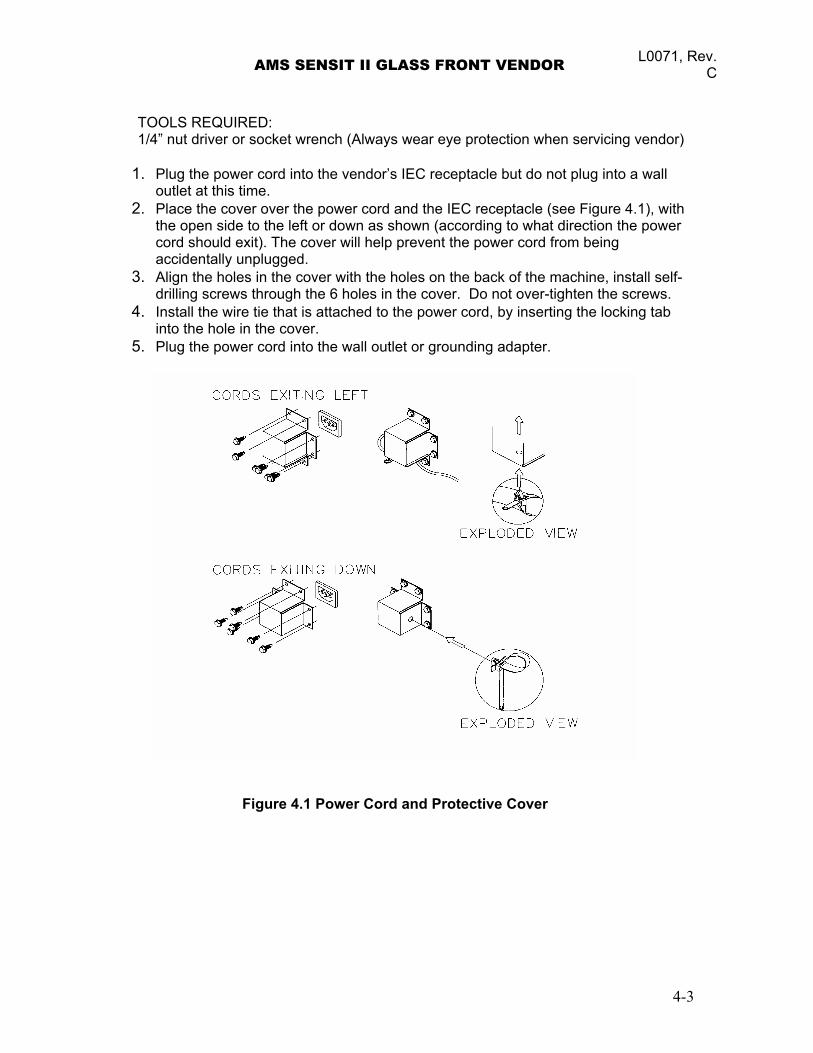
1. Plug the power cord into the vendor’s IEC receptacle but do not plug into a wall outlet at this time.
2. Place the cover over the power cord and the IEC receptacle (see Figure 4.1), with the open side to the left or down as shown (according to what direction the power cord should exit). The cover will help prevent the power cord from being accidentally unplugged.
3. Align the holes in the cover with the holes on the back of the machine, install self-drilling screws through the 6 holes in the cover. Do not over-tighten the screws.
4. Install the wire tie that is attached to the power cord, by inserting the locking tab into the hole in the cover.
5. Plug the power cord into the wall outlet or grounding adapter.
Figure 4.1 Power Cord and Protective Cover
4-3
L0071 Rev.C AMS SENSIT II GLASS FRONT VENDOR 4.2.3 Mounting and Connecting Bill Validators and Card Readers
The AMS vendor will support any NAMA-approved Multi-Drop Bus (MDB) bill validator or card reader. Please read the device manufacturer’s literature before proceeding.
1. Always disconnect power to the control board before servicing. 2. On the inside of the main door, locate and open the access doors on the left side.
Locate the white plastic coin chute which leads from the coin slot on the front of the door. Above the coin chute are (2) metal plates, each fastened to a set of (4) threaded mounting studs which correspond to the mounting holes in the bill validator. Either set of mounting studs may be used for a bill validator or card reader. The lower mounting position is ADA approved for consumers with disabilities.
3. Remove the four nuts that retain the steel cover panel. Remove the steel cover panel, then press out the plastic cover panel in the escutcheon.
4. Refer to the manufacturer’s literature for instructions on accessing the mounting holes in your device. Place the mounting holes over the threaded studs and reinstall the nuts. Some devices may require spacers, which are available from AMS (Part Number 20258).
5. Connect the wiring harness to the MDB harness from the control board. If two devices are installed, connect the second device to the validator.
6. If a coin mechanism has been previously installed, disconnect it from the control board MDB harness and connect it to the validator or second device if installed.
7. Reconnect power to the control board.
4.2.4 Mounting and Connecting Coin Mechanism (Changer) The AMS vendor will support any NAMA-approved Multi-Drop Bus (MDB) Coin
Mechanism. On some export models, the Mars-type Executive Mechanism is supported. Please read the coin mechanism manufacturer’s literature before proceeding.
1. Always disconnect power to the control board before servicing. 2. On the inside of the main door, locate and open the access doors on the left
side. Locate the white plastic coin chute which leads from the coin slot on the front of the door. Below the coin chute are (3) screws which correspond to slots on the back of the changer. Do not adjust these screws.
3. Install the changer by placing the large round opening at the bottom of the each slot over a screw head. Be careful to hold the wiring harnesses in this area out of the way. Once the screw head is inserted in the slot, the changer should drop slightly as the shank of the screw engages the narrow portion of the slot.
4. Tighten the mounting screws (reference manufacturer’s literature). 5. Connect the wiring harness to the bill validator (if applicable) or to the MDB
connector from the control board. 6. Adjust the white plastic coin chute as required to align the chute with the
changer. 7. Reconnect power to the control board.
4-4
AMS SENSIT II GLASS FRONT VENDOR L0071, Rev. C
4.2.5 Test Loading and Configuration
Before putting the vendor on location, it is a good idea to determine the placement of products on the trays. Place at least one product in each helix to check for fit.
1. Remove the cardboard spacers and ties securing the trays. 2. Refer to Section 5.3 for tray vertical adjustments, and Section 5.4 for tray column
configuration when configuring your vendor to suit your product. 3. Make sure the product can slide in and out of the helix easily. If the product is too
snug, it may cause the helix to jam during vending. Place it in a helix with a larger opening.
4. Likewise, if the product is too loose in the helix, it may not vend properly. Use a helix with the smallest opening that will allow the product to slide in and out freely. Refer to Sections 5.6 and 5.7.
5. Place tall, narrow products in a column with a candy pusher bar, which is an adjustable bar used to push the product to one side of the column. Typically these are installed in columns 9 and 0 on the candy trays.
6. Make sure there is adequate clearance between the tops of the packages and the trays above when sliding the trays in and out, and when the product is being vended.
7. This is also a good time to set the end position of the helix to make sure the first product is held securely in the helix. To do this, vend a product from each column. The end position of the helix will automatically be set to the correct position when a product is vended. The control stops the helix the instant the sensor detects a product falling in the hopper.
8. If desired, the end position can be set manually by pulling the helix out of the motor, rotating it, and reinserting it in the motor. Note that this position is reset automatically after the first vend.
9. Test vend the product and add a helix ejector if necessary. The helix ejector is a plastic device installed on the front end of the helix to kick out the product (refer to Section 5.9 Helix Ejector).
4.2.6 Configuring Motors
You will need to configure the motors if you have changed the arrangement of motors or trays.
1. Press the mode switch on the control board (see Figure 3.1, or the decal inside the
access door, for the location of the mode switch). 2. Using the # key, scroll through the menu to “TRAY SETUP”. 3. Press 6 to configure the motors. If the number of motors displayed does not match
the number of motors in the vendor, press 1 * 0 to jog all the motors in the vendor. 4. Watch the display for missing motors that should be connected.
4.2.7 Installing Price Labels After determining the product placement, install the price labels. The labels are
shipped in the envelope with this manual.
1. Insert the bottom edge of the label in the lower groove of the extrusion on the front of the tray.
2. Carefully press in on the the label until it bows enough to snap into the top groove of the extrusion.
4.2.8 Setting Prices
4-5
L0071 Rev.C AMS SENSIT II GLASS FRONT VENDOR
After product placement and installation of the price labels, set the prices into the vendor (refer to Section 6.3 Price Settings).
1. To enter the service mode, press the mode switch on the control board (see
Figure 3.1, or the decal inside the access door, for the location of the mode switch).
2. Using the # key, scroll through the menu to “PRICE”. 3. Press the selection for which you want to set the price (example: A 2). 4. Press 9 to change price. 5. Enter the price and press * * to save the new price. Tip: press * 1 to set the
whole tray to that price, or * 2 to set that price for the entire vendor. 6. Press the mode switch, or close the door, to exit service mode. 7. The prices as set will be maintained by the vendor even if there is a power failure
or if the machine is unplugged: however, prices will need to be reset if the program chip is changed or if the configuration of motors or trays is changed.
4.3 ON-SITE INSTALLATION 4.3.1 Remove the Shipping Boards
1. Split the shipping boards by inserting a crowbar into the slots at either end. 2. If necessary, lift the vendor to remove the broken boards using properly rated
equipment. Do not tilt the vendor. Do not attempt to lift the vendor with a 2-wheel hand truck.
4.3.2 Placing the Vendor in Location
1. Place the vendor within 5 feet of the designated power outlet. 2. For refrigerated models, allow at least 4 inches between the wall and the back of
the vendor for air circulation. 3. Make sure the vendor does not block walkways or exits. 4. Do not place the vendor in a location where it can be struck by vehicles. 5. Leave at least 18 inches between a wall and the hinge side of the vendor to
prevent the door hitting the wall when opened, or use a protective bumper on the wall. At a minimum, the door should be able to open at least 95°.
6. The vendor is designed to meet ADA guidelines for persons in wheelchairs using a parallel approach (side of wheelchair adjacent to front of vendor). Make sure there is adequate room to maneuver a wheelchair into this position in front of the vendor.
4.3.3 Leveling the Vendor
1. On the bottom of the vendor are four (4) threaded leveling legs located at the
corners of the cabinet and a fifth support screw under the door. Before beginning, be sure that all five leveling legs are screwed in completely.
2. With the door closed and locked, check the four main legs and adjust any leg that is not contacting the floor. Make sure the support screw under the door is all the way up and is not contacting the floor.
3. Place a level on top of the cabinet and check the level side-to-side. 4. Adjust the leveling legs on the low side one turn at a time until the cabinet is level. 5. Repeat the last two steps to level the vendor front-to-back. 6. After the vendor is level, adjust the support screw under the door until it contacts
the floor.
4-6
AMS SENSIT II GLASS FRONT VENDOR L0071, Rev. C
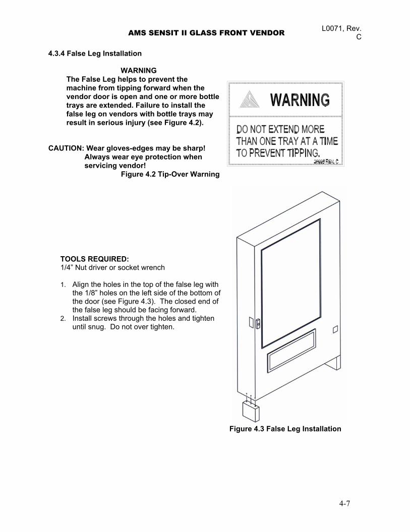
4.3.4 False Leg Installation
WARNING The False Leg helps to prevent the machine from tipping forward when the vendor door is open and one or more btrays are extended. Failure to install the false leg on vendors with bottle trays mayresult in serious injury (see Figure 4.2).
ottle
AUTION: Wear gloves-edges may be sharp!
.2 Tip-Over Warning
OOLS REQUIRED: et wrench
. Align the holes in the top of the false leg with
2. hten
Figure 4.3 False Leg Installation
C
Always wear eye protection when servicing vendor!
Figure 4
T1/4” Nut driver or sock 1
the 1/8” holes on the left side of the bottom of the door (see Figure 4.3). The closed end of the false leg should be facing forward. Install screws through the holes and tiguntil snug. Do not over tighten.
4-7
L0071 Rev.C AMS SENSIT II GLASS FRONT VENDOR
4.3.5 Initial Power-Up and Cool-down When placing a refrigerated machine on a new location it is important to allow the machine to cool to the operating temperature prior to placing product in the machine. All food products are to be pre-packaged. Depending upon the machine’s initial temperature and ambient conditions, it will take about 4 to 5 hours to accomplish this. Normal practice is to place a machine on location and come back the next day to load it. Do not load warm bottle/milk products into vendor. All bottle/milk products are to be pre-chilled. 1. Plug in the vendor. 2. Check that the lights inside the door come on: the chiller may or may not be
running in its cycle at this time. 3. Enter the service mode and check that all settings are correct. 4. Check error codes for problems. 5. Load product after the vendor has cooled. Load one tray at a time, preferably
from the bottom up. 6. Insure vendor is operating properly. If the Health and Safety option is being used,
check vendor again 30 minutes after closing door to ensure NAMA requirements are being met.
4-8
AMS SENSIT II GLASS FRONT VENDOR L0071, Rev. C
5.0 TRAY ADJUSTMENT AND CONFIGURATION
The trays in AMS Sensit II vendors are highly configurable. Practically any combination of wide and narrow columns can be set up on a tray. Before changing the configuration of your trays, make sure to order the parts you will need, such as new helixes, dividers or additional motors. 5.1 SNACK, CANDY, AND FOOD TRAY
5.1.1 Removal
1. To remove the tray, start with the tray pushed to its rearmost position. Lift the
back of the tray up and pull the tray forward about ten inches. Reposition your hands to grasp the tray at its sides and slide the tray out. If the tray is spaced close to the tray above, it may be helpful to raise the front of the tray as you pull it free.
3. When removing a tray, it is not necessary to disconnect the tray harness. The harness is long enough that it will allow a removed tray to be placed on the floor without having to be disconnected.
5.1.2 Installation
1. Before installing the tray, make sure the black plastic covers are on the tabs on
each side at the back of the tray. To install the tray, slide the tray all the way to the rear. It will automatically drop into position. Make sure the harness slack is draped to the outside of the rail.
5.2 BOTTLE TRAY
5.2.1 Removal
1. Disconnect the harness inside the right column in the cabinet. The connections
are labeled corresponding to the letter of the tray (A-F). Push the connector out through the hole in the back of the column.
2. Pull the tray out until it stops. Carefully pull the harness up on top of the tray. 3. Locate the slide rail release levers on both sides of the tray. There should be an
arrow indicating which way to push to release the levers. Note that the lever direction on the right side is opposite the direction on the left side. Push the release levers in the directions indicated and simultaneously pull on the tray.
4. Be sure to push the extended slide rails back into the cabinet before closing the door. Otherwise the slides may be damaged.
5.2.2 Installation: CAUTION: An incorrectly installed tray can disengage from the rails and fall when
extended! It is recommended that installation be performed by at least two people!
1. Fully extend the slide rails in the cabinet and hold in position. 2. Move the ball carriers out to the ends of the slide rails (see Figure 5.1) and hold
in position. 5-1
L0071 Rev.C AMS SENSIT II GLASS FRONT VENDOR
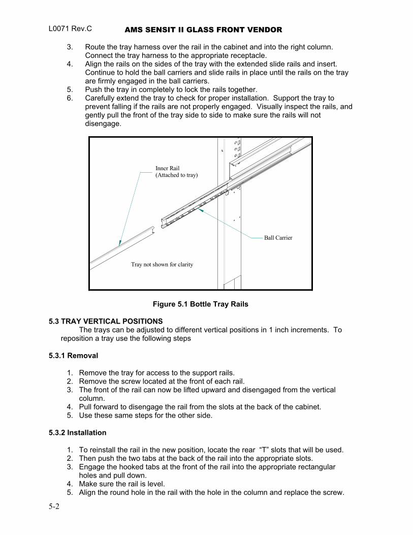
3. Route the tray harness over the rail in the cabinet and into the right column. Connect the tray harness to the appropriate receptacle.
4. Align the rails on the sides of the tray with the extended slide rails and insert. Continue to hold the ball carriers and slide rails in place until the rails on the tray are firmly engaged in the ball carriers.
5. Push the tray in completely to lock the rails together. 6. Carefully extend the tray to check for proper installation. Support the tray to
prevent falling if the rails are not properly engaged. Visually inspect the rails, and gently pull the front of the tray side to side to make sure the rails will not disengage.
Ball Carrier
Inner Rail(Attached to tray)
Tray not shown for clarity
Figure 5.1 Bottle Tray Rails 5.3 TRAY VERTICAL POSITIONS
The trays can be adjusted to different vertical positions in 1 inch increments. To reposition a tray use the following steps
5.3.1 Removal
1. Remove the tray for access to the support rails. 2. Remove the screw located at the front of each rail. 3. The front of the rail can now be lifted upward and disengaged from the vertical
column. 4. Pull forward to disengage the rail from the slots at the back of the cabinet. 5. Use these same steps for the other side.
5.3.2 Installation
1. To reinstall the rail in the new position, locate the rear “T” slots that will be used. 2. Then push the two tabs at the back of the rail into the appropriate slots. 3. Engage the hooked tabs at the front of the rail into the appropriate rectangular
holes and pull down. 4. Make sure the rail is level. 5. Align the round hole in the rail with the hole in the column and replace the screw.
5-2
AMS SENSIT II GLASS FRONT VENDOR L0071, Rev. C
6. Use these same steps for the other side. 7. Reinstall the tray, making sure the harness is routed over the top of the rail and all
slack is draped to the outside of the rail. 5.4 TRAY COLUMN POSITIONS
All trays except bottle trays can be configured by the user to hold 5 to 10 selections (39” cabinets) or 4 to 8 selection (35” cabinets). Typically the vend columns are set to single (2.66”) or double (5.32”) width, to be used with the standard small or large helixes, respectively. Single and double width columns can be configured in any arrangement on the tray by following the procedure below.
Plan your tray arrangement before beginning to determine which extra parts may be required. Contact your distributor to order the necessary parts.
1. Disconnect the harness and remove the tray. Place the tray on a flat, stable work
surface. 2. Reposition, remove, or add tray dividers in the desired locations. To remove the
divider, push rearward then lift. Reverse the procedure to reinstall. 3. It may be necessary to remove a motor and helix in order to install some dividers.
Pull forward on the helix to remove it from the motor. Press down and rearward on the top motor tab to remove the motor from the tray.
4. Reposition the motors to the center of each vend column, using the upper mounting position for the large helix and the lower position for the small helix. It may be easiest to disconnect the motors from the harness first.
5. The harness has 8 or 10 sets of motor connections depending on the model. The first set of connections (at the end of the harness) is position 1, followed by 2, 3, and so on. The last set (nearest the wire jacket) is position 8 (35” cabinets) or 0 (39” cabinets). Starting at the left side of the tray, attach the harness connectors to the motors in order. For double columns, use the even numbered connection and disregard the odd numbered connection. (Example: If the first column on the left is double width, disregard position 1 and attach the connectors for position 2). Each set of connectors has a wide and a narrow connector, corresponding to a wide and a narrow tab on the back of the motor.
6. Place the correct label in front of each column, according to the motor connections used.
7. Reconnect the harness, routing it over the rail and through the back of the column. 8. Reinstall the tray. 9. After changing the tray configuration, it will be necessary to reconfigure the motor
matrix. Refer to Section 6.4.6 Configure
5.5 CHANGING DIVIDERS
1. To remove, push rearward on the divider as far as it will go, then lift it up and out of the tray.
2. Reverse the removal procedure to reinstall.
5-3
L0071 Rev.C AMS SENSIT II GLASS FRONT VENDOR 5.6 SNACK, CANDY AND FOOD HELIX
To remove, pull straight out on the helix to disengage the adapter from the motor. Reverse the removal procedure to reinstall.
5.7 BOTTLE TRAY HELIX
The helix adapters on the bottle trays do not snap in and out as they do on the snack and candy trays. Due to the weight of the bottles, each adapter is retained by a screw in the back of the motor.
1. Pull tray out sufficiently to reach the back of the motor, or remove the tray. 2. The retaining screw is located on the back of the motor and is screwed into the split in
the back end of the helix adapter. 3. After the screw is removed the helix adapter can be pulled out of the motor housing. 4. When reinstalling the helix adapter, the screw must be replaced. The screw should be
reinstalled only until the head contacts the helix adapter. Do not tighten the screw any further or the motor will not be able to turn.
5. Reinstall the tray.
CAUTION: Failure to replace the screw may result in the helix of a loaded column pulling free from the motor and falling out of the tray while the tray is being loaded!
5.8 HELIX ADAPTER
1. To remove, twist the adapter to free the mounting leg from the locking tab. 2. Reverse the removal procedure to reinstall.
5.9 HELIX EJECTOR
The ejector’s function is to cause the product to fall sooner, and therefore stop the helix sooner. This will help retain the next product in the helix coil, especially if they are ‘difficult’ products
1. The helix ejector is pulled off and pressed on the spiral by hand. 2. The ejector is typically positioned half a coil or less from the end of the spiral. 3. The “fin” shaped portion is angled towards the front of the tray. 4. The best position and angle for the ejector is determined by test vending products.
5.10 HELIX ALIGNMENT DEVICE The helix alignment device is installed against the left side of the large helixes to
keep them centered in their columns.
1. To remove, grasp the front of the helix alignment device with pliers and pull or pry upward. Take care not to lose the plastic mounting clips.
2. Reinstall by pressing the plastic mounting clips back into the mounting holes. Note that the mounting flange goes toward the spiral.
5-4
AMS SENSIT II GLASS FRONT VENDOR L0071, Rev. C
5.11 MOTOR POSITIONS
Motor position can be changed sideways for different columns, and there are two mounting positions on the snack tray. The lower and upper positions are used for the small and large spirals, respectively.
1. To remove, press down and rearward on the top mounting tab, then pull the lower
mounting legs out of the mounting slots. 2. Reverse the removal procedure to reinstall.
5.12 BOTTLE ALIGNMENT DEVICE
The bottle alignment device will, in some cases, inhibit the rotation of bottles as they are vended. It has two uneven-length legs. It can be installed with either leg on top, depending on which works best.
1. To remove the bottle alignment device, remove the screws from the underside of
the tray that hold it in place. 2. To reinstall, reverse the removal procedure.
5.13 BOTTLE TIPPER BAR
The bottle tipper bar is typically used with carbonated beverage bottles. The bottles have a dimpled bottom which permits them to straddle the spiral and stand upright. The tipper bar restrains the top of the bottle so that it falls bottom first, rather than tumbling off the tray.
1. To remove, bow the bar until one end can be pulled free from the support bracket.
Take care not to lose the plastic bushings in the supports. 2. To reinstall, reverse the removal procedure.
5.14 AVOIDING PRODUCT HANG-UPS
Avoid large products, such as chips, from ‘hanging-up’ between the tray and the glass by loading them ‘left corner first’ into the helix. The bottom left corner of the bag should be in front of the helix to let the helix push the bottom out first (see Figure 5.2). An incorrect loading may cause the bag to fall top first, which could lead to a hang-up. Loading ‘left corner first’ prevents the product from falling top first.
Incorrect Correct Figure 5.2 Large Bag Vending
5-5
L0071 Rev.C AMS SENSIT II GLASS FRONT VENDOR
5.15 TALL PRODUCT VENDING
Place tall, narrow products in a column with a candy pusher bar. Typically these are installed in columns 9 and 0 on the candy trays. Rotate the bar upward or downward to the desired position. It should hold the product upright, but not pinch or bind the product.
5.16 CANDY PUSHER BAR INSTALLATION
The candy pusher bar is an adjustable bar that mounts to any tray divider to keep tall candies from falling sideways (see Figure 5.3). Four pusher bars are provided with the standard glass front vendor. 1. Snap the pusher bar into the retainer. 2. Rotate the pusher bar to accommodate the product.
Figure 5.3 Pusher Bar Installation
5.17 1.5” HELIX TRAY ADJUSTMENT AND LOADING 5.17.1 General Information
Some vendors are equipped with a 1.5” Helix Tray designed to vend small candy, gum and mint packs. The 1.5” Helix Tray can also be ordered separately; the following part numbers describe what installation kits are available:
Part No. 21564 – Kit, 1.5” Helix Tray, Reduced Depth (35”) Part No. 21565 – Kit, 1.5” Helix Tray, Reduced Depth (39”)
5.17.2 TRAY ADJUSTMENT AND LOADING
5-6
AMS SENSIT II GLASS FRONT VENDOR L0071, Rev. C
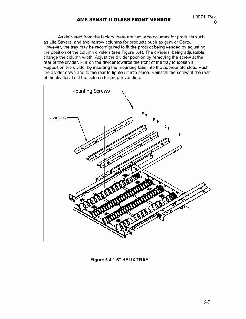
As delivered from the factory there are two wide columns for products such as Life Savers, and two narrow columns for products such as gum or Certs. However, the tray may be reconfigured to fit the product being vended by adjusting the position of the column dividers (see Figure 5.4). The dividers, being adjustable, change the column width. Adjust the divider position by removing the screw at the rear of the divider. Pull on the divider towards the front of the tray to loosen it. Reposition the divider by inserting the mounting tabs into the appropriate slots. Push the divider down and to the rear to tighten it into place. Reinstall the screw at the rear of the divider. Test the column for proper vending.
Figure 5.4 1.5” HELIX TRAY
5-7

L0071 Rev.C AMS SENSIT II GLASS FRONT VENDOR
5-8
AMS SENSIT II GLASS FRONT VENDOR L0071, Rev. C
6.0 SERVICE PROGRAMMING
SERVICE MODE Access the service mode by pressing the mode switch on the control board (see
Figure 3.1). After displaying any errors, the first function is displayed. Press # or * to scroll through the errors and functions. Return to vend mode by closing the door, pressing the mode switch or allowing the 2 minute time-out to occur.
For convenience, there is a decal on the right-hand side inside the cabinet that presents all the information in this section in a flow-chart format.
6.1 ERROR CODES
Any errors that have been recorded will be displayed when the mode switch is pressed. Refer to Sections 6 and 7 for a description, along with troubleshooting tips for correcting the errors. 1. # NEXT ERROR – View the next top level error code. 2. 1. SUBLVL ERRORS – Displays any sublevel error codes for MDB devices. 3. 0. CLEAR ERROR – Erases the error code from memory.
6.2 ACCOUNTING DATA
Limited sales information can be displayed directly on the vendor display. More detailed sales information is contained in the DEX data. This data can be collected with any DEX data collection system.
1. HIST. VENDS – Displays number of vends since initialization of the control board. 2. HIST. CASH – Displays the total sales since initialization of the control. 3. RESET. VENDS – Displays the number of vends since the last reset. 4. RESET. CASH – Displays the total sales since the last reset. 5. HIST. SELN. – Displays number of vends (per selection) since initialization. 6. CLEAR VALUES – Clears RESET. VENDS and RESET. CASH. 7. SERIAL NUMBER – Allows programming of the serial number that will appear in
field ID101 in the DEX data. The user may also choose to have this programmed serial number used in place of the changer serial number in field CA101.
6.3 FILL/DISPENSE
The FILL/DISPENSE function allows the user to add coins to the changer or dispense coins from the changer.
1. SELECT TUBE 1-5 - To dispense coins, press 1 through 5 (for a 5-tube changer) to
dispense from tubes 1-5. Tubes are numbered starting with the lowest denomination. The control will display the value of the coin being dispensed and the total number of coins in that tube.
2. OR INSERT COIN - To fill the changer, simply drop coins in the coin slot. The display will show the value of the coin and the total number of coins in that tube. Note that coins can also be added through the back of the changer. However, the control will not be have an accurate count of the coins in the tube unless the tube is filled completely. When the high-level sensor in the tube detects coins, the control will set the correct coin count for that tube.
6-1
L0071 Rev.C AMS SENSIT II GLASS FRONT VENDOR 6.4 DELAYED SALES
The user can delay sales of specified selections to give the product time to settle or cool. The delay must be manually started each time sales are to be delayed. To prevent sales automatically at specific times of day, use SALES BLOCKING (refer to Section 6.8). 1. START DELAY – Begins the sales delay timer. Before starting the timer, choose
menu item “5. EDIT SEL’NS” to specify which selections will be delayed. Customers will not be able to purchase those selections until the delay period ends.
2. CANCEL DELAY – Stops the delay timer and allows vending of all selections. 3. SET DELAY – Adjust the time of the delay timer in 15 minute increments. 4. CLEAR ALL – Clears all selections that were chosen to be delayed. 5. EDIT SEL’NS – View and change the delay status of all selections. The user can
choose to apply the delay to a single selection, a tray, or all selections in the vendor.
6.5 TEMPERATURE
The user can set the refrigeration temperature and review the cooling performance of the vendor.
1. CURRENT TEMP – Displays the actual temperature in the cabinet. 2. SETPOINT – The user can adjust the refrigeration setpoint in 1°F increments. This
is the temperature at which the refrigeration system will turn on. The refrigeration unit will turn off when the actual temperature is 3°F below the setpoint. If the vendor has Health and Safety software, and is vending perishable food, the temperature must be set to 41°F or below. A set point of 40°F is recommended.
3. START LOG – Begin recording the actual temperature every minute for the first 30 minutes of cooling after the door is closed.
4. VIEW LOG – View the temperatures recorded in the cooling log. The reading number, temperature, date and time are displayed. Press 1 or 2 to scroll up or down through the readings.
TIP: To view a temperature history of the previous 2 days, use DATA LOGS (refer to
Section 6.12).
6.6 PRICE SETTINGS
Before setting prices, install a changer so that the control will recognize the proper scaling factor for your currency.
1. ENTER SELECTION – Enter the tray letter or number and then the column number
for the first selection to be priced. The current price for the selection will be displayed. Press 9 to edit, then enter the new price, making sure to enter all digits after the decimal point. The decimal is placed automatically based on the scaling factor from the changer.
Example: For a price of $1.50, enter 1 5 0. 2. The user can choose to apply the new price to the selection (**), all selections on the
tray (*1), or all selections in the vendor (*2). TIP: It is usually faster to set all selections to the most common price in the vendor (*2),
then change individual trays or items that have a different price.
6-2
AMS SENSIT II GLASS FRONT VENDOR L0071, Rev. C
6.7 TRAY SETUP 6.7.1 Test Motors
Enter the selection number to be tested, or press * to see the following options for testing multiple motors.
1-JOG ALL – All motor positions in the vendor will be tested. Each motor will be
turned only a very small amount, so that products loaded in the vendor will not be dispensed. The display will show the number of the motor being jogged, or it will show a message that a motor is missing.
2-JOG TRAY – All motor positions on the selected tray will be tested. The display will show the number of the motor being jogged, or it will show a message that a motor is missing.
3-CHECK JAMMED – The control will attempt to run each motor that has caused a jammed motor error. The status of the motor will be displayed afterward.
6.7.2 Link Motors
The user can link adjacent selections of the same product on the same tray. The leftmost linked selection is the master selection. All other linked selections are vended using the selection number and price of the master selection. Linked selections are vended sequentially for better product rotation. Entering the selection number of any linked selection will default to the master selection number, and the control will vend the next linked selection in the sequence. 1. NEW LINK – Enter the tray where the motors are to be linked, then enter the first
and last column numbers (left to right) to be linked. 2. VIEW / EDIT – The user can view, change, or delete existing links. 3. CLEAR ALL – This will delete all current links. The prices of the previously linked
selections will remain the same as their master selections until new prices are set.
6.7.3 Home Switch Only the seventh and eighth tray positions in the vendor can be set to use motors
with home position switches. Enter the tray letter (G or H) or number (7 or 8) and press 1 to change the setting. The setting must match the type of motors used on the tray, or the motors will not work.
When the setting is Y for YES, the switches on all of the motors on the selected tray are enabled. When a product selection is made the motor will only turn one full turn then stop. If the sensors did not detect a drop then “PLEASE MAKE ANOTHER SELECTION” will be displayed.
When the state is N for NO, the switches on all of the motors are disabled. When a product selection is made the motor will turn until the sensors detect a drop. If after several seconds no drop occurs the motor will stop and “PLEASE MAKE ANOTHER SELECTION” will be displayed.
6-3
L0071 Rev.C AMS SENSIT II GLASS FRONT VENDOR 6.7.4 Delayed Stop
The user can program a delayed stop of up to one second to allow a motor to continue running after the product has been dispensed.
1. ENTER SELECTION – Enter the number of the selection to be delayed, enter 9 to
edit, then enter the time in tenths of a second. The decimal point is placed automatically.
Example: Entering 8 will program a delay of 0.8 seconds. The user can save the programmed delay to the selection, the entire tray, or all
selections in the vendor. Linked selections will use the delay programmed for the master selection.
6.7.5 Letter / Number – The user can choose to designate the trays in the vendor with letters (A-H) or numbers (1-8). Depending on the setting, the top tray is designated “A” or “1”. Numbers are typically used only in countries that do not use alphabetic characters. If the setting is changed, the trays should be relabeled accordingly.
6.7.6 Configure – The control will find all connected motors in the vendor and display the
total number. The configuration of connected motors is stored in memory. If a configured motor is later found to be missing during a vend, an error message will be generated to alert the service person that the motor is disconnected.
6.8 MDB SETTINGS 6.8.1 Force Vend – The factory default is “N” for no. If set to “Y”, the customer must make a
selection before the control will allow a full refund. If the selected product cannot be dispensed, a full refund can be returned to the customer (refer to Section 6.5.3).
6.8.2 No Cheat – The factory default is “N” for no. If set to “Y”, the control will not allow a
vend unless correct change can be returned to the customer. If disabled, the control will allow the customer to be short-changed up to $1.00.
6.8.3 Change Bill – The factory default is “N” for no. If set to “Y”, the customer can insert a
bill and receive a full refund in coins by pressing the coin return button. Note that using CHANGE BILL will override force vend.
6.8.4 Hold Lost Credit – The factory default is “Y” for yes. If set to “Y”, any credit that can’t
be returned to the customer following a vend will be maintained on the display for 15 minutes. The customer can use this credit to purchase additional items.
6.8.5 Multi-Vend – The factory default is “N” for no. If set to “Y”, the vendor will not return
change following a vend. The customer can make multiple purchases with the original credit. The customer must push the coin return button to refund the remaining credit.
6.8.6 Lev2 Coin Mech – The factory default is “N” for no. If set to “Y”, the vendor will treat
the coin mechanism as a level 2 device. Vendor must be powered down before change will take effect. AMS recommends that this option remain as “N” for no.
6-4
AMS SENSIT II GLASS FRONT VENDOR L0071, Rev. C
6.9 OPTIONS 6.9.1 Message – The user can customize the scrolling message that is displayed when the
vendor is idle. Other words can be customized by using the CREATE CUSTOM option in the LANGUAGE menu (refer to Section 6.5.8).
Write out the desired scrolling message first. The message to be shown on
the scrolling display can be up to 50 characters, including letters, numbers, punctuation and spaces. Next, rewrite the message, replacing each Character of the message using the appropriate Enter chart entry (see the Keypad Mapping Chart below). For example, entering *5 in the message option will print the character X on the display (please note that *5 counts as only one character, the letter X, in the scrolling message).
Select the message option to enter a message. The controller will prompt the
user to “CHANGE Y/N.” Press 1 to change within five (5) seconds, or press any other key to exit. Key in the message created using the chart.
To correct mistakes press * H (backspace). Press # to save the new message.
Character Enter Character Enter Character Enter A A T * 3 - 8 B B U * 4 SAVE # C 1 V * E , 9 D 2 W * F . 0 E C X * 5 BACKSPACE * H F D Y * 6 * * 7 G 3 Z * G / * 8 H 4 1 * * 1 < * # I E 2 * * 2 > * 9 J F 3 * * 3 = * 0 K 5 4 * * 4 ! * * A L 6 5 * * 5 ? * * B M G 6 * * 6 : * * C N * A 7 * * 7 ; * * D O * B 8 * * 8 # * * E P * 1 9 * * 9 $ * * F Q * 2 0 * * 0 % * * G R * C SPACE H & * * H S * D + 7 ‘ * * #
6.9.2 Prize – The factory default is “0” for none. The user can set the vendor to give away a
free product after a predetermined number of successful vends. Enter the number of vends between free vends, up to 9999. Setting the number to “0” will disable the prize option.
6-5
L0071 Rev.C AMS SENSIT II GLASS FRONT VENDOR 6.9.3 Language 6.9.3.1 Primary – The user is presented with a menu of available languages. The user may
choose the primary language for the display of all messages Note that Service Mode messages are available in Primary language only.
6.9.3.2 Secondary – If desired, the user can select a secondary language for the display of
all messages. Messages will be displayed first in the primary language, then in the secondary language.
6.9.3.3 Create Custom – The user can create customized versions of words or enter words
in another language. For convenience, the primary language messages can be used as a starting point (refer to Section 6.5.7). The user can then select words to modify. After creating the customized messages, set the primary or secondary language to CUSTOM.
6.9.4 Product Sensor – If set to “Y”, the vendor will use the product sensor (optional) to
determine if there is product in the delivery bin. The control board will not allow vending until any product in the delivery bin is removed. A “REMOVE PRODUCT” message will be displayed. This feature is used primarily when vending glass bottles and products that can be damaged by other falling products.
6.10 SALES BLOCKING
The factory default is “N” for no. The user can set up to four time periods each day during which sales will be disabled or blocked. For each time period, the user can select which days of the week the period will be active.
1-4 SET PERIODS – Enter the number (1-4) of the time period to edit. Enter the time when sales blocking will start, then enter the time when sales blocking will end. Finally, select the days of the week when the blocking period will be active. If a blocking period extends from one day into the next, it will be active or inactive based on the day it starts.
6.11 CLOCK SETTINGS
1. TIME AND DATE – Enter the current time and date. This information will be used for data logs and error records.
2. DAYLIGHT SAVINGS – The factory default is “N” for no. If set to “Y”, the time is automatically adjusted for Daylight Savings Time.
3. DISPLAY CLOCK – The factory default is “Y”. The current time will appear on the display beneath the scrolling message when the vendor is not in use.
4. 12/24 FORMAT – The user can choose to display the time in 12-hour or 24-hour (military) format. The factory default is 12-hour format.
6.12 FREE VEND
The factory default is “N” for no. The vendor can be quickly set to vend all products for free. Prices are ignored while FREE VEND is enabled. The original prices will be restored when FREE VEND is turned off.
1. VIEW / EDIT – The current setting is displayed, and the user can change the
setting. A warning will be displayed if FREE VEND is turned on.
6-6
AMS SENSIT II GLASS FRONT VENDOR L0071, Rev. C
6.13 AUXILIARY OUTPUT
The auxiliary output is a 5VDC signal lasting 100 milliseconds following a successful vend. This signal can be used to trigger user-supplied external devices. As of this writing, AMS does not supply such accessory devices and cannot offer technical assistance for such devices. This feature is provided only as a convenience to those users of advanced technical skill who wish to connect such a device to their AMS vendor and have sufficient electronic expertise to do so
1. VIEW / EDIT – The current setting is displayed, and the user can change the
setting. Enabling the auxiliary output will not harm the vendor or affect the performance of the vendor in any way.
6.14 DATA LOGS
The user can review recorded data on vendor temperature, power outages, and door openings. This data is sometimes helpful in diagnosing problems with the vendor. These logs are cleared whenever the software is changed.
1. TEMPERATURE – The temperature log contains temperature measurements taken
at half-hour intervals over the previous two days. The display shows the recording number, the recorded temperature, and the time and date of the recording. The log holds 96 measurements, with number 1 being the most recent.
2. POWER – The power outage log records power failure information. The display shows the recording number, whether power went ON or OFF, the temperature in the cabinet, and the time and date of the recording. The log holds 10 recordings, with number 1 being the most recent.
3. DOOR SWITCH – The door switch log records door openings and closings. The display shows the recording number, whether the door was OPENED or CLOSED, the temperature in the cabinet, and the time and date of the recording. The log holds 10 recordings, with number 1 being the most recent.
6-7

L0071 Rev.C AMS SENSIT II GLASS FRONT VENDOR
6-8
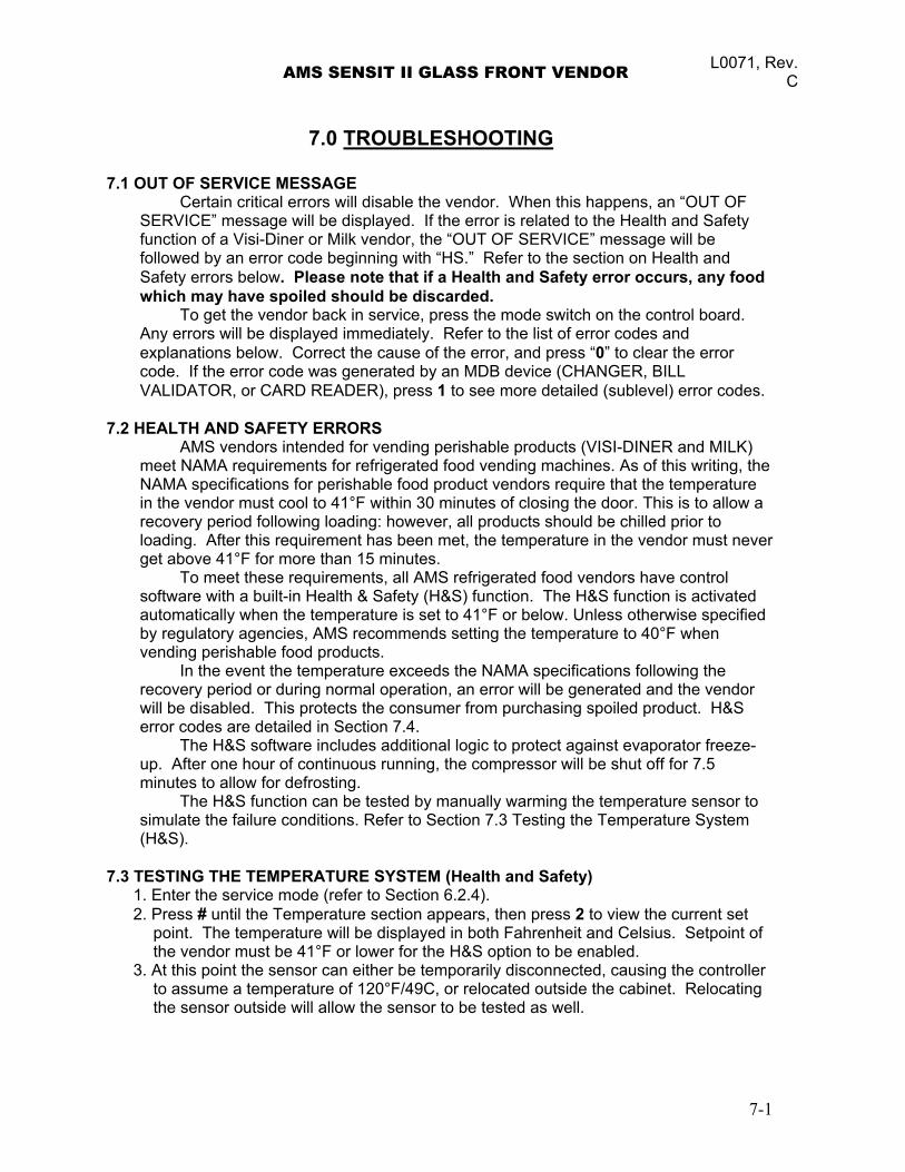
AMS SENSIT II GLASS FRONT VENDOR L0071, Rev. C
7.0 TROUBLESHOOTING
7.1 OUT OF SERVICE MESSAGE Certain critical errors will disable the vendor. When this happens, an “OUT OF
SERVICE” message will be displayed. If the error is related to the Health and Safety function of a Visi-Diner or Milk vendor, the “OUT OF SERVICE” message will be followed by an error code beginning with “HS.” Refer to the section on Health and Safety errors below. Please note that if a Health and Safety error occurs, any food which may have spoiled should be discarded.
To get the vendor back in service, press the mode switch on the control board. Any errors will be displayed immediately. Refer to the list of error codes and explanations below. Correct the cause of the error, and press “0” to clear the error code. If the error code was generated by an MDB device (CHANGER, BILL VALIDATOR, or CARD READER), press 1 to see more detailed (sublevel) error codes.
7.2 HEALTH AND SAFETY ERRORS
AMS vendors intended for vending perishable products (VISI-DINER and MILK) meet NAMA requirements for refrigerated food vending machines. As of this writing, the NAMA specifications for perishable food product vendors require that the temperature in the vendor must cool to 41°F within 30 minutes of closing the door. This is to allow a recovery period following loading: however, all products should be chilled prior to loading. After this requirement has been met, the temperature in the vendor must never get above 41°F for more than 15 minutes.
To meet these requirements, all AMS refrigerated food vendors have control software with a built-in Health & Safety (H&S) function. The H&S function is activated automatically when the temperature is set to 41°F or below. Unless otherwise specified by regulatory agencies, AMS recommends setting the temperature to 40°F when vending perishable food products.
In the event the temperature exceeds the NAMA specifications following the recovery period or during normal operation, an error will be generated and the vendor will be disabled. This protects the consumer from purchasing spoiled product. H&S error codes are detailed in Section 7.4.
The H&S software includes additional logic to protect against evaporator freeze-up. After one hour of continuous running, the compressor will be shut off for 7.5 minutes to allow for defrosting.
The H&S function can be tested by manually warming the temperature sensor to simulate the failure conditions. Refer to Section 7.3 Testing the Temperature System (H&S).
7.3 TESTING THE TEMPERATURE SYSTEM (Health and Safety)
1. Enter the service mode (refer to Section 6.2.4). 2. Press # until the Temperature section appears, then press 2 to view the current set
point. The temperature will be displayed in both Fahrenheit and Celsius. Setpoint of the vendor must be 41°F or lower for the H&S option to be enabled.
3. At this point the sensor can either be temporarily disconnected, causing the controller to assume a temperature of 120°F/49C, or relocated outside the cabinet. Relocating the sensor outside will allow the sensor to be tested as well.
7-1
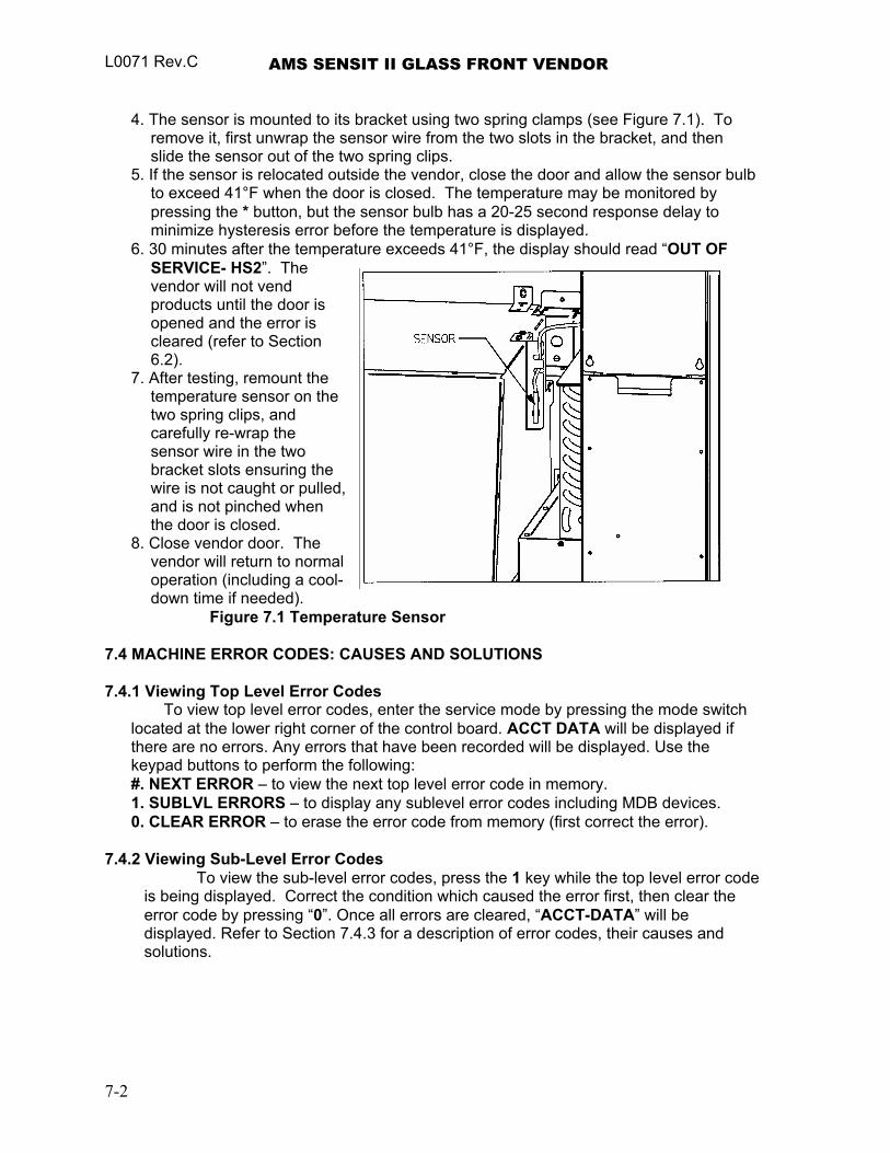
L0071 Rev.C AMS SENSIT II GLASS FRONT VENDOR
4. The sensor is mounted to its bracket using two spring clamps (see Figure 7.1). To
remove it, first unwrap the sensor wire from the two slots in the bracket, and then slide the sensor out of the two spring clips.
5. If the sensor is relocated outside the vendor, close the door and allow the sensor bulb to exceed 41°F when the door is closed. The temperature may be monitored by pressing the * button, but the sensor bulb has a 20-25 second response delay to minimize hysteresis error before the temperature is displayed.
6. 30 minutes after the temperature exceeds 41°F, the display should read “OUT OF SERVICE- HS2”. The vendor will not vend products until the door is opened and the error is cleared (refer to Section 6.2).
7. After testing, remount the temperature sensor on the two spring clips, and carefully re-wrap the sensor wire in the two bracket slots ensuring the wire is not caught or pulled, and is not pinched when the door is closed.
8. Close vendor door. The vendor will return to normal operation (including a cool-down time if needed). Figure 7.1 Temperature Sensor
7.4 MACHINE ERROR CODES: CAUSES AND SOLUTIONS
7.4.1 Viewing Top Level Error Codes
To view top level error codes, enter the service mode by pressing the mode switch located at the lower right corner of the control board. ACCT DATA will be displayed if there are no errors. Any errors that have been recorded will be displayed. Use the keypad buttons to perform the following: #. NEXT ERROR – to view the next top level error code in memory. 1. SUBLVL ERRORS – to display any sublevel error codes including MDB devices. 0. CLEAR ERROR – to erase the error code from memory (first correct the error).
7.4.2 Viewing Sub-Level Error Codes
To view the sub-level error codes, press the 1 key while the top level error code is being displayed. Correct the condition which caused the error first, then clear the error code by pressing “0”. Once all errors are cleared, “ACCT-DATA” will be displayed. Refer to Section 7.4.3 for a description of error codes, their causes and solutions.
7-2
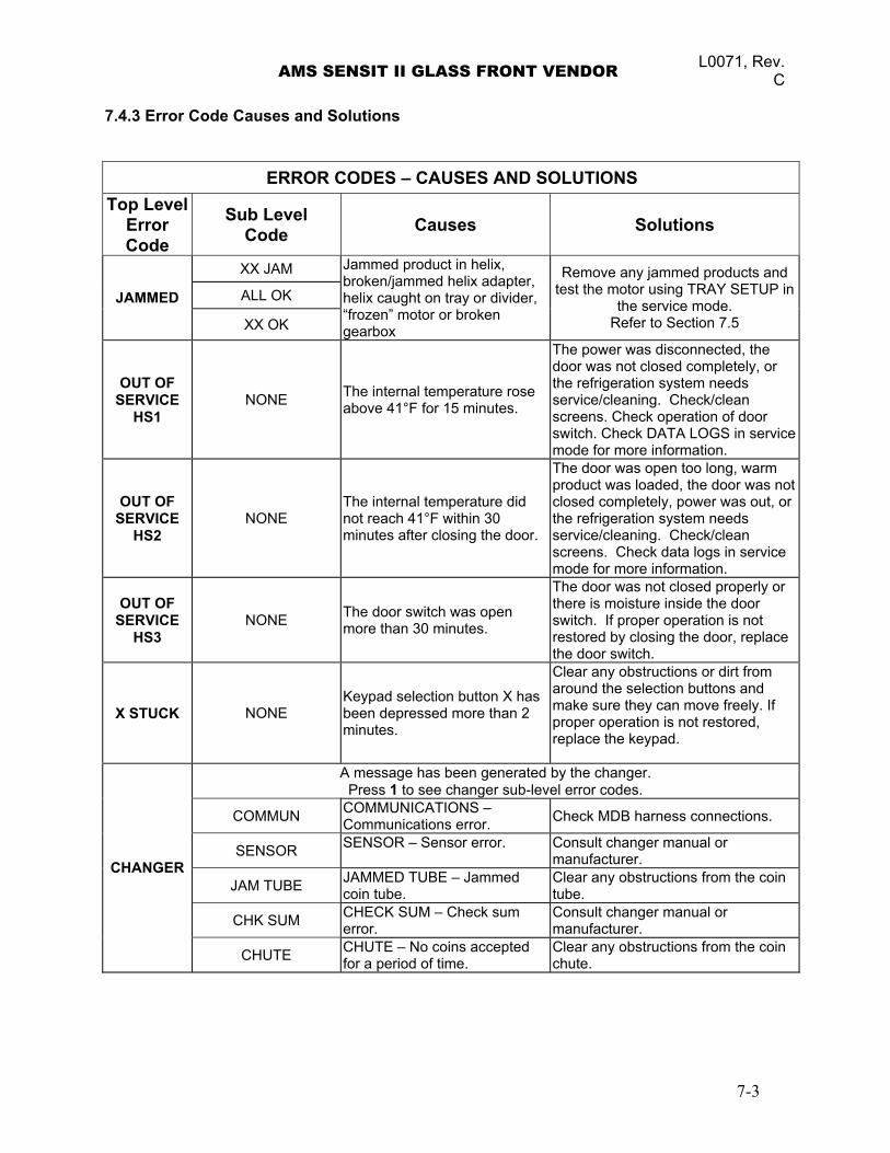
AMS SENSIT II GLASS FRONT VENDOR L0071, Rev. C
7.4.3 Error Code Causes and Solutions
ERROR CODES – CAUSES AND SOLUTIONS Top Level
Error Code
Sub Level Code Causes Solutions
XX JAM
ALL OK JAMMED
XX OK
Jammed product in helix, broken/jammed helix adapter, helix caught on tray or divider, “frozen” motor or broken gearbox
Remove any jammed products and test the motor using TRAY SETUP in
the service mode. Refer to Section 7.5
OUT OF SERVICE
HS1 NONE The internal temperature rose
above 41°F for 15 minutes.
The power was disconnected, the door was not closed completely, or the refrigeration system needs service/cleaning. Check/clean screens. Check operation of door switch. Check DATA LOGS in service mode for more information.
OUT OF SERVICE
HS2 NONE
The internal temperature did not reach 41°F within 30 minutes after closing the door.
The door was open too long, warm product was loaded, the door was not closed completely, power was out, or the refrigeration system needs service/cleaning. Check/clean screens. Check data logs in service mode for more information.
OUT OF SERVICE
HS3 NONE The door switch was open
more than 30 minutes.
The door was not closed properly or there is moisture inside the door switch. If proper operation is not restored by closing the door, replace the door switch.
X STUCK NONE Keypad selection button X has been depressed more than 2 minutes.
Clear any obstructions or dirt from around the selection buttons and make sure they can move freely. If proper operation is not restored, replace the keypad.
A message has been generated by the changer. Press 1 to see changer sub-level error codes.
COMMUN COMMUNICATIONS – Communications error. Check MDB harness connections.
SENSOR SENSOR – Sensor error. Consult changer manual or manufacturer.
JAM TUBE JAMMED TUBE – Jammed coin tube.
Clear any obstructions from the coin tube.
CHK SUM CHECK SUM – Check sum error.
Consult changer manual or manufacturer.
CHANGER
CHUTE CHUTE – No coins accepted for a period of time.
Clear any obstructions from the coin chute.
7-3
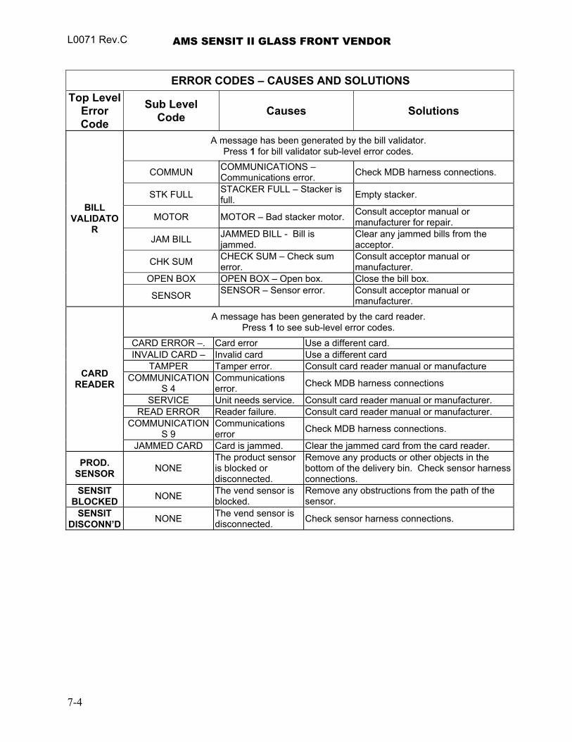
L0071 Rev.C AMS SENSIT II GLASS FRONT VENDOR
ERROR CODES – CAUSES AND SOLUTIONS Top Level
Error Code
Sub Level Code Causes Solutions
A message has been generated by the bill validator. Press 1 for bill validator sub-level error codes.
COMMUN COMMUNICATIONS – Communications error. Check MDB harness connections.
STK FULL STACKER FULL – Stacker is full. Empty stacker.
MOTOR MOTOR – Bad stacker motor. Consult acceptor manual or manufacturer for repair.
JAM BILL JAMMED BILL - Bill is jammed.
Clear any jammed bills from the acceptor.
CHK SUM CHECK SUM – Check sum error.
Consult acceptor manual or manufacturer.
OPEN BOX OPEN BOX – Open box. Close the bill box.
BILL VALIDATO
R
SENSOR SENSOR – Sensor error. Consult acceptor manual or manufacturer.
A message has been generated by the card reader. Press 1 to see sub-level error codes.
CARD ERROR –. Card error Use a different card. INVALID CARD – Invalid card Use a different card
TAMPER Tamper error. Consult card reader manual or manufacture COMMUNICATION
S 4 Communications error. Check MDB harness connections
SERVICE Unit needs service. Consult card reader manual or manufacturer. READ ERROR Reader failure. Consult card reader manual or manufacturer.
COMMUNICATIONS 9
Communications error Check MDB harness connections.
CARD READER
JAMMED CARD Card is jammed. Clear the jammed card from the card reader.
PROD. SENSOR NONE
The product sensor is blocked or disconnected.
Remove any products or other objects in the bottom of the delivery bin. Check sensor harness connections.
SENSIT BLOCKED NONE The vend sensor is
blocked. Remove any obstructions from the path of the sensor.
SENSIT DISCONN’D NONE The vend sensor is
disconnected. Check sensor harness connections.
7-4
AMS SENSIT II GLASS FRONT VENDOR L0071, Rev. C
7.5 CLEARING JAMMED MOTOR
If one or more motors and helixes become jammed, the display will scroll each individually jammed motor on the display for two (2) seconds.
Energized vend motors can turn a helix with considerable torque, creating a possible entrapment hazard. Disconnect power to the vendor or control board before freeing a jammed helix or motor. Always restrain or block the helix before freeing a jammed or caught product.
CAUTION: Use caution when freeing jammed product! Refer to 2.2.4 Helix
Motion and Jamming! Clear any jammed products from the indicated vend columns. To reset the error, refer to Section 6.1.7, Tray Setup, then press “1.*.2”. The
control will attempt to run the jammed motors. If the motors run successfully, the control will display that selection followed by “OK”. If the motor had been taken out of the motor matrix, it will be re-established in the matrix. When all motors have been re-established in the matrix the display will read “ALL OK”.
7.6 WATER FORMATION IN THE CABINET
Water formation in the cabinet indicates an air leak which allows moist air to continually enter the cabinet and condense on the evaporator. 1. Make sure the refrigeration unit cover gasket is sealing properly all the way around.
In particular, check the openings where the refrigeration lines and drain tube pass through the cover. These openings should be sealed completely around the lines and tube with duct putty.
2. Make sure the door is properly tightened so that it makes contact with the gasket on all sides.
3. Make sure there are no foreign objects interfering with the vend door, and the vend door closes properly.
7-5
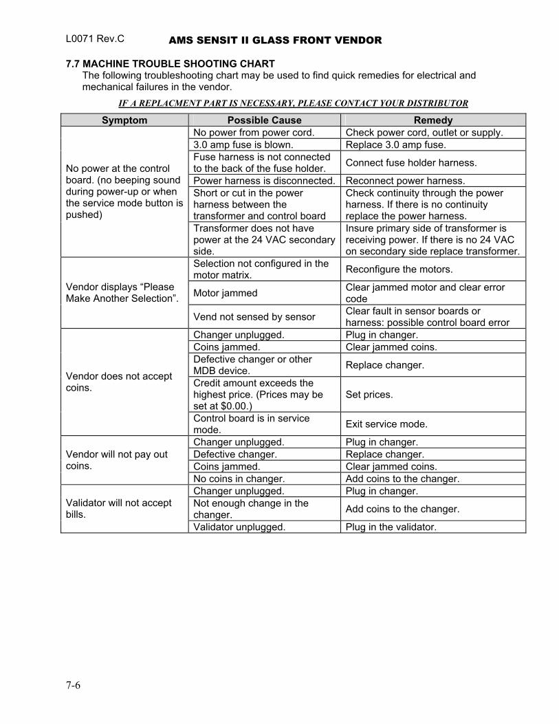
L0071 Rev.C AMS SENSIT II GLASS FRONT VENDOR 7.7 MACHINE TROUBLE SHOOTING CHART
The following troubleshooting chart may be used to find quick remedies for electrical and mechanical failures in the vendor.
IF A REPLACMENT PART IS NECESSARY, PLEASE CONTACT YOUR DISTRIBUTOR
Symptom Possible Cause Remedy No power from power cord. Check power cord, outlet or supply. 3.0 amp fuse is blown. Replace 3.0 amp fuse. Fuse harness is not connected to the back of the fuse holder. Connect fuse holder harness.
Power harness is disconnected. Reconnect power harness. Short or cut in the power harness between the transformer and control board
Check continuity through the power harness. If there is no continuity replace the power harness.
No power at the control board. (no beeping sound during power-up or when the service mode button is pushed)
Transformer does not have power at the 24 VAC secondary side.
Insure primary side of transformer is receiving power. If there is no 24 VAC on secondary side replace transformer.
Selection not configured in the motor matrix. Reconfigure the motors.
Motor jammed Clear jammed motor and clear error code
Vendor displays “Please Make Another Selection”.
Vend not sensed by sensor Clear fault in sensor boards or harness: possible control board error
Changer unplugged. Plug in changer. Coins jammed. Clear jammed coins. Defective changer or other MDB device. Replace changer.
Credit amount exceeds the highest price. (Prices may be set at $0.00.)
Set prices.
Vendor does not accept coins.
Control board is in service mode. Exit service mode.
Changer unplugged. Plug in changer. Defective changer. Replace changer. Coins jammed. Clear jammed coins.
Vendor will not pay out coins.
No coins in changer. Add coins to the changer. Changer unplugged. Plug in changer. Not enough change in the changer. Add coins to the changer. Validator will not accept
bills. Validator unplugged. Plug in the validator.
7-6
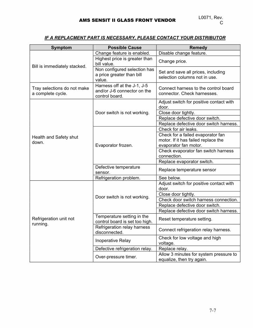
AMS SENSIT II GLASS FRONT VENDOR L0071, Rev. C
IF A REPLACMENT PART IS NECESSARY, PLEASE CONTACT YOUR DISTRIBUTOR
Symptom Possible Cause Remedy Change feature is enabled. Disable change feature. Highest price is greater than bill value. Change price.
Bill is immediately stacked. Non configured selection has a price greater than bill value.
Set and save all prices, including selection columns not in use.
Tray selections do not make a complete cycle.
Harness off at the J-1, J-5 and/or J-6 connector on the control board.
Connect harness to the control board connector. Check harnesses.
Adjust switch for positive contact with door. Close door tightly. Replace defective door switch.
Door switch is not working.
Replace defective door switch harness.Check for air leaks. Check for a failed evaporator fan motor. If it has failed replace the evaporator fan motor. Check evaporator fan switch harness connection.
Evaporator frozen.
Replace evaporator switch. Defective temperature sensor. Replace temperature sensor
Health and Safety shut down.
Refrigeration problem. See below. Adjust switch for positive contact with door. Close door tightly. Check door switch harness connection.Replace defective door switch.
Door switch is not working.
Replace defective door switch harness.Temperature setting in the control board is set too high. Reset temperature setting.
Refrigeration relay harness disconnected. Connect refrigeration relay harness.
Inoperative Relay Check for low voltage and high voltage.
Defective refrigeration relay. Replace relay.
Refrigeration unit not running.
Over-pressure timer. Allow 3 minutes for system pressure to equalize, then try again.
7-7

L0071 Rev.C AMS SENSIT II GLASS FRONT VENDOR
7-8
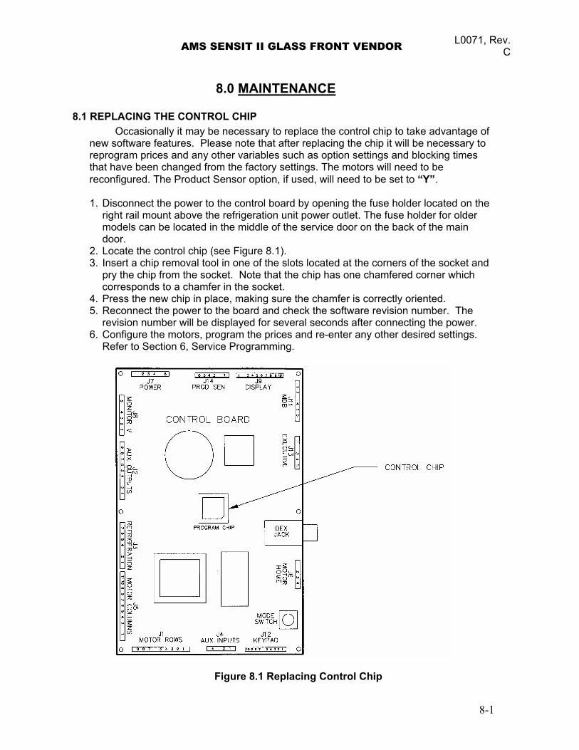
AMS SENSIT II GLASS FRONT VENDOR L0071, Rev. C
8.0 MAINTENANCE
8.1 REPLACING THE CONTROL CHIP Occasionally it may be necessary to replace the control chip to take advantage of
new software features. Please note that after replacing the chip it will be necessary to reprogram prices and any other variables such as option settings and blocking times that have been changed from the factory settings. The motors will need to be reconfigured. The Product Sensor option, if used, will need to be set to “Y”. 1. Disconnect the power to the control board by opening the fuse holder located on the
right rail mount above the refrigeration unit power outlet. The fuse holder for older models can be located in the middle of the service door on the back of the main door.
2. Locate the control chip (see Figure 8.1). 3. Insert a chip removal tool in one of the slots located at the corners of the socket and
pry the chip from the socket. Note that the chip has one chamfered corner which corresponds to a chamfer in the socket.
4. Press the new chip in place, making sure the chamfer is correctly oriented. 5. Reconnect the power to the board and check the software revision number. The
revision number will be displayed for several seconds after connecting the power. 6. Configure the motors, program the prices and re-enter any other desired settings.
Refer to Section 6, Service Programming.
Figure 8.1 Replacing Control Chip
8-1
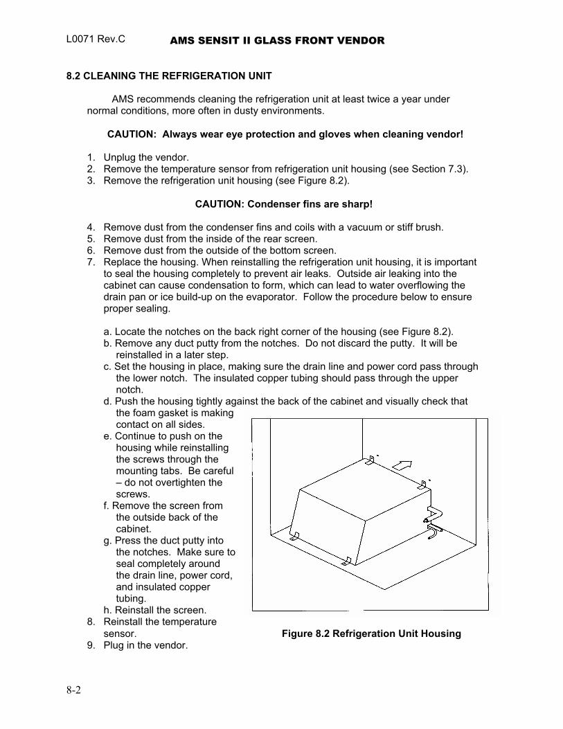
L0071 Rev.C AMS SENSIT II GLASS FRONT VENDOR
8.2 CLEANING THE REFRIGERATION UNIT
AMS recommends cleaning the refrigeration unit at least twice a year under normal conditions, more often in dusty environments.
CAUTION: Always wear eye protection and gloves when cleaning vendor!
1. Unplug the vendor. 2. Remove the temperature sensor from refrigeration unit housing (see Section 7.3). 3. Remove the refrigeration unit housing (see Figure 8.2).
CAUTION: Condenser fins are sharp!
4. Remove dust from the condenser fins and coils with a vacuum or stiff brush. 5. Remove dust from the inside of the rear screen. 6. Remove dust from the outside of the bottom screen. 7. Replace the housing. When reinstalling the refrigeration unit housing, it is important
to seal the housing completely to prevent air leaks. Outside air leaking into the cabinet can cause condensation to form, which can lead to water overflowing the drain pan or ice build-up on the evaporator. Follow the procedure below to ensure proper sealing. a. Locate the notches on the back right corner of the housing (see Figure 8.2). b. Remove any duct putty from the notches. Do not discard the putty. It will be
reinstalled in a later step. c. Set the housing in place, making sure the drain line and power cord pass through
the lower notch. The insulated copper tubing should pass through the upper notch.
d. Push the housing tightly against the back of the cabinet and visually check that the foam gasket is making contact on all sides.
e. Continue to push on the housing while reinstalling the screws through the mounting tabs. Be careful – do not overtighten the screws.
f. Remove the screen from the outside back of the cabinet.
g. Press the duct putty into the notches. Make sure to seal completely around the drain line, power cord, and insulated copper tubing.
h. Reinstall the screen. 8. Reinstall the temperature
sensor. Figure 8.2 Refrigeration Unit Housing 9. Plug in the vendor.
8-2
AMS SENSIT II GLASS FRONT VENDOR L0071, Rev. C
8.3 CLEANING THE VENDOR CABINET
Clean the vendor cabinet as necessary using mild household cleaners and water. Apply the cleaning solution to a cloth or sponge and gently wipe the vendor surfaces to clean. 1. Do not use chemicals or solvents. These can damage the paint and plastic trim. 2. Do not use abrasive cleaners. 3. Do not use a water jet. 4. Do not let water or cleaning solutions contact electrical or electronic components. 5. Clean the glass front inside and out with a good window cleaner.
8.4 CLEANING THE PLASTIC DOOR LINER
Some vendors use a door liner made from ABS plastic. This liner should be cleaned with a mild detergent diluted in water. Do not use chemical solvents or harsh detergents as these products could crack the liner.
8.5 LUBRICATION WITH LITHIUM GREASE
Once a year the bottle tray rail ball bearings and door moving parts should be lubricated with white lithium grease. 1. Pull out the tray. The tray rail is constructed of three telescoping channel sections.
Apply a light coating of grease on the outside of the first two sections, along the top and bottom edges.
2. Apply grease on the inside of the last two sections along the top and bottom. 3. Apply grease (or similar lubricant) to the door lock bolt threads and the door hinges
as necessary. 4. Wipe off excess grease. No other lubrication is required.
8-3

L0071 Rev.C AMS SENSIT II GLASS FRONT VENDOR
8-4
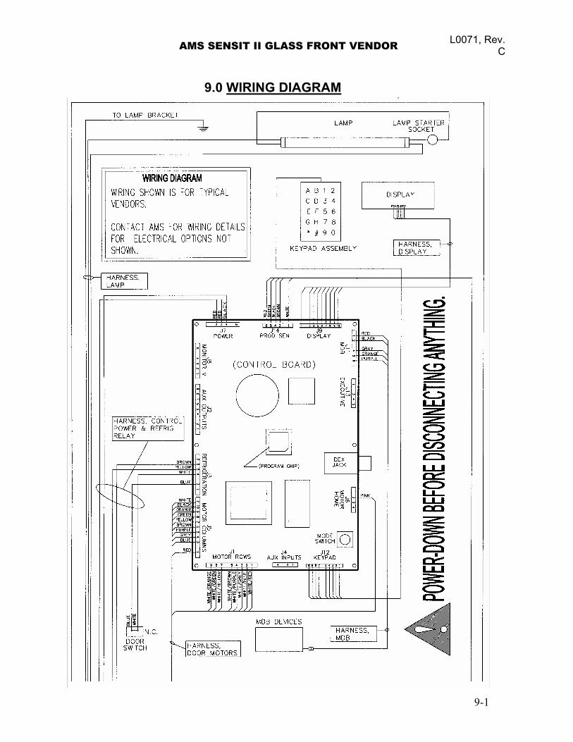
AMS SENSIT II GLASS FRONT VENDOR L0071, Rev. C
9.0 WIRING DIAGRAM
9-1

L0071 Rev.C AMS SENSIT II GLASS FRONT VENDOR
Figure 9.1 Typical Wiring Diagram, Sheet 1 of 4
9-2
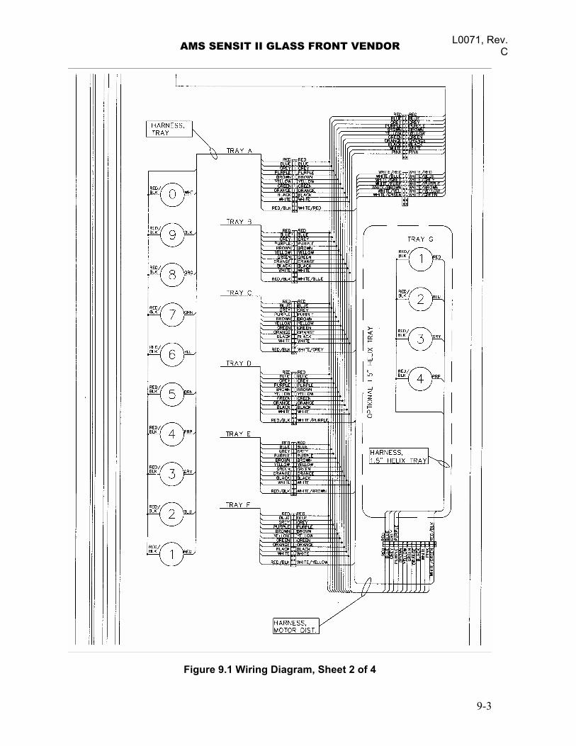
AMS SENSIT II GLASS FRONT VENDOR L0071, Rev. C
Figure 9.1 Wiring Diagram, Sheet 2 of 4
9-3
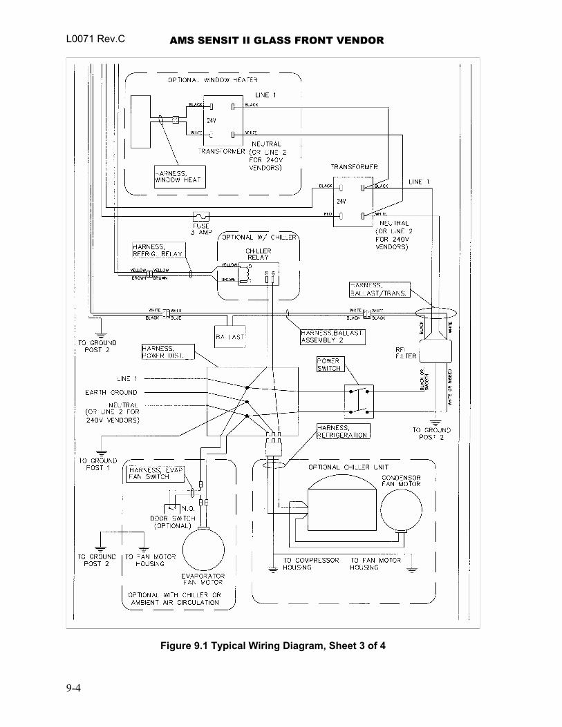
L0071 Rev.C AMS SENSIT II GLASS FRONT VENDOR
Figure 9.1 Typical Wiring Diagram, Sheet 3 of 4
9-4
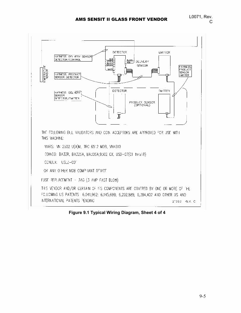
AMS SENSIT II GLASS FRONT VENDOR L0071, Rev. C
Figure 9.1 Typical Wiring Diagram, Sheet 4 of 4
9-5

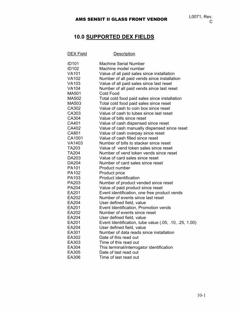
AMS SENSIT II GLASS FRONT VENDOR L0071, Rev. C
10.0 SUPPORTED DEX FIELDS DEX Field Description ID101 Machine Serial Number ID102 Machine model number VA101 Value of all paid sales since installation VA102 Number of all paid vends since installation VA103 Value of all paid sales since last reset VA104 Number of all paid vends since last reset MA501 Cold Food MA502 Total cold food paid sales since installation MA503 Total cold food paid sales since reset CA302 Value of cash to coin box since reset CA303 Value of cash to tubes since last reset CA304 Value of bills since reset CA401 Value of cash dispensed since reset CA402 Value of cash manually dispensed since reset CA801 Value of cash overpay since reset CA1001 Value of cash filled since reset VA1403 Number of bills to stacker since reset TA203 Value of vend token sales since reset TA204 Number of vend token vends since reset DA203 Value of card sales since reset DA204 Number of card sales since reset PA101 Product number PA102 Product price PA103 Product identification PA203 Number of product vended since reset PA204 Value of paid product since reset EA201 Event identification, one free product vends EA202 Number of events since last reset EA204 User defined field, value EA201 Event Identification, Promotion vends EA202 Number of events since reset EA204 User defined field, value EA201 Event Identification, tube value (.05, .10, .25, 1.00) EA204 User defined field, value EA301 Number of data reads since installation EA302 Date of this read out EA303 Time of this read out EA304 This terminal/interrogator identification EA305 Date of last read out EA306 Time of last read out
10-1

L0071 Rev.C AMS SENSIT II GLASS FRONT VENDOR
10-2
AMS SENSIT II GLASS FRONT VENDOR L0071, Rev. C
11.0 OPTIONAL EQUIPMENT Part No. 21564 – Kit, 1.5” Helix Tray, Reduced Depth (35”) Part No. 21565 – Kit, 1.5” Helix Tray, Reduced Depth (39”) A four-selection helix tray that mounts below the bottom tray. Part No. 20449 - Kit, Candy Pusher The candy pusher is an adjustable bar that mounts to any tray divider to keep tall candies from falling sideways. Four of these are provided with the standard glass front vendor. Part No. 20450 - Kit, Helix Splitter The helix splitter is a plastic divider that can be inserted into a small helix to divide each coil into two product openings, thereby doubling product capacity. The helix splitter works best with narrow products such as Life Savers. Part No. 20535 - Kit, Cup Rail, Small Helix Part No. 20536 - Kit, Cup Rail, 4” Helix Part No. 20723 - Kit, Cup Rail, 3” Helix The cup rail is a flat plastic bar that can be placed inside the helix to provide a flat surface for rigid flat-bottomed packages that otherwise do not stay upright when placed in a helix. Examples would be drink boxes or bottles, or individual serving cups of soup, pudding, etc. Part No. 20675 - Kit, Ventilator, 110V (35”) Part No. 20676 - Kit, Ventilator, 110V (39”)
The ventilator kit provides outside air circulation through the vendor. Part No. 21709 - Kit, Chiller, ¼ hp, 120V, (35”), NAMA Cabinet, Sensit II, AMS WV Part No. 21710 - Kit, Chiller, ¼ hp, 240V, (35”), NAMA Cabinet, Sensit II, AMS WV Part No. 21711 - Kit, Chiller, ¼ hp, 240V, (39”), NAMA Cabinet, Sensit II, AMS WV Part No. 21712 - Kit, Chiller, ¼ hp, 120V, (39”), NAMA Cabinet, Sensit II, AMS WV Part No. 21713 - Kit, Chiller, ¼ hp, 120V, (35”), NAMA Cabinet, Sensit II, INTAMS (MEX) Part No. 21714 - Kit, Chiller, ¼ hp, 120V, (39”), NAMA Cabinet, Sensit II, INTAMS (MEX)
The chiller kit is a refrigeration unit that can be used to convert an ambient vendor into a chilled vendor. Part No. 20664 - Kit, Banking Spacer Part No. 21166 - Kit, False Leg False leg to be installed on all machines having 2 or more bottle trays to prevent machine tipping during loading. Failure to install the false leg could result in serious injury. Part No. 20665 - Kit, Window, Dual Pane Glass (35”) Part No. 20427 - Kit, Window, Dual Pane Glass (39”)
The dual pane glass window is insulated and features a thicker pane on the exterior side.
11-1

L0071 Rev.C AMS SENSIT II GLASS FRONT VENDOR
11-2
AMS SENSIT II GLASS FRONT VENDOR L0071, Rev. C
12.0 LIMITED WARRANTY
Automated Merchandising Systems Inc. (AMS) warrants this equipment to the Original Purchaser only, for a period of one (1) year from the date of shipment, to be free under normal use and service from defects in material or workmanship, and for three (3) years on the refrigeration unit, electronic control board, and the two sensor boards. The refrigeration unit consists of the compressor, fan motors, relay, and the sealed components of the system. Light bulbs, glass, and painted surfaces are not covered by this warranty.
Should any part prove defective within the warranty period, AMS will repair or replace (at its option) the defective component. AMS will provide normal ground shipment for parts replaced under warranty. This warranty does not cover the labor or other costs associated with removal and reinstallation of a defective component. All defective components, at the option of AMS, are to be returned, properly packaged, freight prepaid, to AMS or to the authorized dealer or distributor from whom the equipment was purchased for verification of the defect. Prior to returning any parts for replacement the customer is to contact the AMS Service Department at (304) 725-6921 for return authorization. AMS reserves the right to refuse any collect shipment.
This warranty applies only if the equipment has been serviced and maintained in strict accordance with the instructions presented in this service manual and no unauthorized repair, alteration, or disassembly has been done. Any defects caused by improper power source, abuse of the product, accident, alteration, vandalism, improper service techniques, or damage incurred during return shipment due to improper packaging will not be covered by this warranty. Likewise, any equipment that has had the serial number removed, defaced or otherwise altered will not be covered by this warranty.
AMS reserves the right to make changes or improvements in its products
without notice and without obligation, and without being required to make corresponding changes or improvements in equipment already manufactured or sold.
12-1

L0071 Rev.C AMS SENSIT II GLASS FRONT VENDOR
12-2