Embed Size (px)
Citation preview

Ocean GOinG SalvaGe veSSel A 10,570 BHP Salvage Vessel Preliminary Design by:
Sea Tools Engineering
Prepared By: Daniel Place - Alex Donaldson - Marc Woolliscroft - Jacob Trithart
Undergraduate Students, Department of Naval Architecture and Marine Engineering The University of Michigan
Prepared For:
Matthew Collette Professor, Department of Naval Architecture and Marine Engineering
Administrator Administrator, U.S. Maritime Administration
Capt. Lawson Brigham, USCG (Ret), PhD Deputy Director, U.S. Arctic Research Commission
Mr. R. Keith Michel President, Society of Naval Architects and Marine Engineers
Mr. Ronald Kiss Past President, Webb Institute
Pradeep Nayyar Program Manager, Maritime Administration, U.S. Department of Transportation
Project Due Date: April 21, 2010

2
Table of Contents List of Tables .................................................................................................................................. 4 List of Figures ................................................................................................................................ 6 1.0 – Executive Summary ............................................................................................................... 7 2.0 – Technical Summary ............................................................................................................... 9
2.1 – Introduction ........................................................................................................................ 9 2.2 - Requirements ...................................................................................................................... 9 2.3 – Principal Characteristics .................................................................................................... 9 2.4 – Hull Selection................................................................................................................... 10 2.5 – General Arrangements ..................................................................................................... 10 2.6 – Engine Selection .............................................................................................................. 11 2.7 – Generator Selection .......................................................................................................... 11 2.8 – Propulsion Design ............................................................................................................ 12 2.9 – Weights Estimation .......................................................................................................... 12 2.10 – Floodable Length ........................................................................................................... 12 2.11 – Damage Stability ............................................................................................................ 13 2.12 – Midship Analysis ........................................................................................................... 13 2.13 – Seakeeping Analysis ...................................................................................................... 13 2.14 – Maneuvering Analysis ................................................................................................... 14 2.15 – Conclusion ..................................................................................................................... 14
3.0 – Introduction .......................................................................................................................... 15 3.1 – Requirements ................................................................................................................... 15 3.2 – Principal Characteristics .................................................................................................. 15
4.0 – Hull Form Design ................................................................................................................ 16 4.1 – Initial Point Design .......................................................................................................... 16 4.2 –Hull Selection and Optimization ....................................................................................... 16 4.3 – Lines Drawing .................................................................................................................. 17
5.0 – Capabilities .......................................................................................................................... 19 5.1 – Salvage ............................................................................................................................. 19 5.2 – Towing ............................................................................................................................. 19 5.3 – Fire Fighting..................................................................................................................... 19 5.4 – Oil Recovery .................................................................................................................... 20
6.0 – General Arrangements ......................................................................................................... 21 6.1 – Bulkhead Placement......................................................................................................... 21 6.2 – Floodable Length ............................................................................................................. 22 6.3 Deck House ......................................................................................................................... 22
7.0 – Propulsion and Powering ..................................................................................................... 25 7.1 – Resistance ........................................................................................................................ 25 7.2 – Prime Mover Selection .................................................................................................... 26
7.2.1 – Initial Point Design and Selection............................................................................. 26 7.2.2 – Analysis of Selected Engines .................................................................................... 26
7.3 – Propulsion Design ............................................................................................................ 28 7.4 – Towing and Bollard Pull .................................................................................................. 30 7.5 – Electrical Power Estimation ............................................................................................. 31 7.6 – Generator Selection .......................................................................................................... 31 7.7 – One Line Diagram............................................................................................................ 31
8.0 – Intact and Damage Stability ................................................................................................. 33

3
8.1 – Intact Stability .................................................................................................................. 33 8.1.1 – U.S. Coast Guard Wind Heel Requirements ............................................................. 33 8.1.2 – Towing Stability Criteria .......................................................................................... 33 8.1.3 – Topside Icing ............................................................................................................ 33 8.1.4 – Cross Curves of Stability .......................................................................................... 34 8.1.5 – Bonjean Curves ......................................................................................................... 34
8.2 – Damaged Stability ............................................................................................................ 35 9.0 – Midship Analysis ................................................................................................................. 37
9.1 – ABS Regulations .............................................................................................................. 37 9.2 – Moment and Shear Diagram ............................................................................................ 37 9.3 – Midship Analysis ............................................................................................................. 38
10.0 Structural Analysis ................................................................................................................ 39 10.1 Ice Strengthened Regions ................................................................................................. 39 10.2 Framing ............................................................................................................................. 40
11.0 – Maneuvering Analysis ....................................................................................................... 42 11.1 – Initial Sizing ................................................................................................................... 42 11.2 – Maneuvering Prediction Program .................................................................................. 42 11.3 – Bow Thruster ................................................................................................................. 42
12.0 – Seakeeping Analysis .......................................................................................................... 44 12.1 – Seakeeper Results .......................................................................................................... 44 12.2 – Natural Periods............................................................................................................... 47 12.3 – Working Condition Analysis ......................................................................................... 47
13.0 – Fleet Justification ............................................................................................................... 49 14.0 Economic Analysis ............................................................................................................... 51 15.0 – Recommendations for Future Work ................................................................................... 55 16.0 – Conclusion ......................................................................................................................... 56 Appendix A – Lines Drawing ....................................................................................................... 57 Appendix B – Outboard & Inboard Profiles ................................................................................. 58 Appendix C – General Arrangements ........................................................................................... 59 Appendix D – Propeller Geometry ............................................................................................... 60 Appendix E – Structural Drawings ............................................................................................... 61 Appendix F – Powering Specifications......................................................................................... 62 Appendix G – Machinery Specifications ...................................................................................... 63 Appendix H – Maneuvering.......................................................................................................... 64 Appendix I – Floodable Length .................................................................................................... 65 Appendix J – Intact Stability......................................................................................................... 66 Appendix K – Damaged Stability ................................................................................................. 67 Appendix L – Seakeeping Results ................................................................................................ 68 Appendix M – Structural Calculations ......................................................................................... 69

4
List of Tables
Table 1 – Principal Characteristics ................................................................................................. 7 Table 2 – General Engine Characteristics ....................................................................................... 8 Table 3 – Propeller Characteristics ................................................................................................. 8 Table 4 – Principal Characteristics ............................................................................................... 10 Table 5 – Engine Characteristics .................................................................................................. 11 Table 6 – Generator Characteristics .............................................................................................. 11 Table 7 – Propeller Optimization Characteristics ......................................................................... 12 Table 8 – Intact Stability at Four Loading Conditions ................................................................. 12 Table 9 – Midship Analysis .......................................................................................................... 13 Table 10 – Seakeeping Analysis ................................................................................................... 14 Table 11 – Maneuvering Analysis ................................................................................................ 14 Table 12 – Client Requirements ................................................................................................... 15 Table 13 – Principal Characteristics ............................................................................................. 15 Table 14 – Regression Analysis Results ....................................................................................... 16 Table 15 – Principal Dimensions and Hydrostatics ...................................................................... 17 Table 16 – Station Spacing ........................................................................................................... 18 Table 17 – Salvage Characteristics ............................................................................................... 19 Table 18 – Firefighting Characteristics......................................................................................... 20 Table 19 – Bulkhead Locations .................................................................................................... 21 Table 20 - Deckhouse Accommodations ...................................................................................... 23 Table 21 - Percentage of Total Drag ............................................................................................. 25 Table 22 – 8 Cylinder Engine Characteristics .............................................................................. 27 Table 23 – 16 Cylinder Engine Characteristics ............................................................................ 27 Table 24 – Propeller Characteristics ............................................................................................. 28 Table 25 – Generator Characteristics ............................................................................................ 31 Table 26 - MARAD Design Letter 3 Damaged Stability Criterion .............................................. 35 Table 27 – Damage Stability Results ............................................................................................ 36 Table 28 – ABS Longitudinal Strength Calculations ................................................................... 37 Table 29 - Maximum Bending Moments ...................................................................................... 37 Table 30 – Midship Section Strength Properties .......................................................................... 38 Table 32 – Ice Belt Definitions ..................................................................................................... 39 Table 31 – Plating Thicknesses..................................................................................................... 39 Table 33 – Required and Actual Section Moduli.......................................................................... 40 Table 34 – Stiffener Sizing ........................................................................................................... 40 Table 35 – Maneuvering Analysis ................................................................................................ 42 Table 36 - North Pacific Sea State Characteristics ....................................................................... 44 Table 37 - Natural Periods ............................................................................................................ 47 Table 38 - Worst Cast MII Results ............................................................................................... 47 Table 39 – MII Risk Levels .......................................................................................................... 48 Table 40 - Incidents near the Aleutian Island ............................................................................... 49 Table 41 - Crew Cost Breakdown ................................................................................................. 51 Table 42 - Build Cost Breakdown ................................................................................................ 51 Table 43 - Operational Cost Breakdown ...................................................................................... 51 Table 44 - 15 Year Expense Summary ......................................................................................... 51 Table 45 - Salvage Revenue ......................................................................................................... 52

5
Table 46 - Specific Fuel Consumption ......................................................................................... 52 Table 47 - Average Fuel Prices ..................................................................................................... 52 Table 48 - Dutch Harbor Fuel Cost............................................................................................... 53 Table 49 - Seattle Fuel Cost .......................................................................................................... 53 Table 50 - Juneau Fuel Cost.......................................................................................................... 53 Table 51 - Required Returns ......................................................................................................... 53 Table 52 - Towing Summary ........................................................................................................ 54 Table 53 - Required Freight Rate.................................................................................................. 54

6
List of Figures
Figure 1 – Lines Drawing ............................................................................................................. 10 Figure 2 – Inboard Profile ............................................................................................................. 11 Figure 3 – Floodable Length Diagram .......................................................................................... 13 Figure 4 - Double Hard Chine Hull Form – LOA = 44.2 m ......................................................... 17 Figure 5 - Faired Hull Form – ....................................................................................................... 17 Figure 6 - Fire Monitor Location .................................................................................................. 20 Figure 7 - Interior General Arrangements .................................................................................... 21 Figure 8 – Bulkhead Placement .................................................................................................... 21 Figure 9 – Floodable Length Analysis .......................................................................................... 22 Figure 10 – Propulsion System Rendering ................................................................................... 25 Figure 11 - Total Resistance and Delivered Thrust versus Speed ................................................ 26 Figure 12 - Engine Layout Rendering .......................................................................................... 28 Figure 13 - Propeller and Kort Nozzles ........................................................................................ 29 Figure 14 - Cavitation versus Vessel Speed ................................................................................. 29 Figure 15 - Propeller Coefficients versus Vessel Speed ............................................................... 30 Figure 16 - 12,000 mt Barge (380' x 100') with 11' Draft ............................................................. 31 Figure 17 - One-Line Diagram ..................................................................................................... 32 Figure 18 - Towline Pull Criterion................................................................................................ 33 Figure 19 – GZ Curves ................................................................................................................. 34 Figure 20 – Bonjean Curves ......................................................................................................... 35 Figure 21 – Load Distribution for the Full Load Condition ......................................................... 38 Figure 22 - Bow Thruster Regression ........................................................................................... 43 Figure 23 - 16 kn RAO, 0º ............................................................................................................ 44 Figure 24 - 16 kn RAO, 30º .......................................................................................................... 44 Figure 25 - 16 kn RAO, 90º .......................................................................................................... 45 Figure 26 - 16 kn RAO, 140º ........................................................................................................ 45 Figure 27 - 16 kn RAO, 180º ........................................................................................................ 45 Figure 28 - Heave Response ......................................................................................................... 46 Figure 29 - Roll Response............................................................................................................. 46 Figure 30 - Pitch Response ........................................................................................................... 46 Figure 31 - Critical MII Locations ................................................................................................ 47 Figure 32 - Tug Fleet Locations.................................................................................................... 50

7
1.0 – Executive Summary
The Maritime Administration (the Agency) and the Society for Naval Architects and Marine Engineers (SNAME) have expressed a strong need for the capabilities of a 10,000 horsepower ocean going salvage tug in the proximity of the Aleutian Islands. It was the task of Sea Tools Engineering to develop a preliminary design for such a tug. The initial requirements set forth by the Agency and SNAME included a minimum 10,000 hp installed power, ice strengthened for operation in and around the Aleutian Islands, and commercial operations, other than salvage, which would break even on the vessel’s operating cost and amortize the build cost after 15 years. The vessel was also to have a region of operation that would allow efficient response to salvage missions and operate in a safe, secure, and environmentally responsible manner. Sea Tools Engineering has successfully designed a tug as desired by the Agency and SNAME. The tug will be United States flagged and therefore comply with the American Bureau of Shipping (ABS) classification rules, United States Coast Guard requirements, and the Code of Federal Regulations. The Sea Tools tug satisfies all of the client requirements, exceeds classification standards, and has several unique features which make it a feasible choice for deployment in the Aleutian Islands. The principal dimensions for the tug were determined via a regression analysis of similar existing ocean going salvage tugs. Unique and important features of the tug include Fire Fighting II classification, oil recovery capabilities, safe conditions for the crew to pilot the vessel and operate the winch in sea state six, and a variable propulsion system that reduces fuel consumption if full power be unnecessary. An overview of the principal characteristics for the Sea Tools design is listed in Table 1.
LOA (m) 66.8 LWL (m) 65.6 B (m) 15.0 D (m) 7.49 T (m) 5.63 C 0.52 B
Design Speed (kn) 16 Displacement (MT) 2941 Endurance (nm) 2640 Installed Power (kW) 7882 Bollard Pull (tons-force) 129.7 Crew Capacity 30 Cost (millions USD) 26.8
Table 1 – Principal Characteristics The floodable length and damaged stability characteristics of the Sea Tools tug are outstanding and will survive a head on collision resulting in failure of the collision bulkhead. The powering analysis and propeller optimization determined the tug has exceptional bollard pull and minimal cavitation during the bollard pull condition. Powering characteristics are presented in Table 2 and propeller characteristics are presented in Table 3.

8
MCREngine 7,882 kW (10,570 BHP) @ 800 rpm (kW) Engines 4 Brand ElectroMotive Models EMD 8-710GC-T2 and EMD 16-710GC-T2
Table 2 – General Engine Characteristics
Characteristic Value Quantity 2 DP 4.0 m P controllable AE/AO 0.85 RPM 188 rpm Maximum Efficiency 46 %
Table 3 – Propeller Characteristics The tug is economically viable and will break even after 15 years of operation. This will be accomplished by performing towing operations between Seattle and Juneau in addition to salvage missions. A fleet of three vessels will be utilized which will leave at least one tug on call at all times for salvage missions. Each Sea Tools tug will require a crew of 12 and is prepared to house 18 additional salvors. Each sailor has ample room in the deckhouse and will be comfortable when performing extended length salvage missions. This report is a preliminary design and contains details of the hull design and optimization, propeller optimization and selection, weight estimation and weight centers, powering calculations, damaged stability, structures, maneuvering and seakeeping predictions, and economic analysis.

9
2.0 – Technical Summary
A summary of the technical aspects of the report are summarized in this section.
2.1 – Introduction
It has been indicated by the Society of Naval Architects and Marine Engineers, as well as the United States Maritime Administration, that there is currently a strong need for powerful, 10,000 BHP, ocean going salvage vessels in and around the Aleutian Islands and Gulf of Alaska. Because of this need, these organizations have put forth a design competition, in which we have partaken, in order to fulfill this design need. Our preliminary design not only fulfills all necessary salvage operations, but also implements several other commercial applications in order pay for the costs of the vessel over a 15 year period. The remaining details of our vessel design are presented in this report. Details include principal dimensions, hull regression and selection, general arrangement, prime mover and machinery selections, propulsion design, weight and centers estimation, ship intact and damage stability, floodable length, structural analysis of the midship section, a seakeeping analysis, and a maneuvering estimation.
2.2 - Requirements
The requirements which governed the design of our vessel are listed below. MARAD and SNAME Design Competition Requirements
• Location: Aleutian Islands Chain & Arctic Waters • Power: Minimum of 10,000 HP (7,457 kW) installed • Structure: Ice strengthened for Arctic waters • Economic: Commercial applications other than salvaging
Break even with costs after 15 years of continuous operation • Response: Fast response time from doing other commercial applications • Operation: Safe, secure and environmentally responsible
Designer Specified Requirements
• Seakeeping: Operate safely in conditions up to sea state six
2.3 – Principal Characteristics
The principal dimensions for the salvage vessel were determined via a regression analysis of similar existing containerships and iterated until the best solution was found. Developing a brand new hull form can be a very expensive process and unnecessary if many similar vessels have been previously contracted. Initial dimensions for the Sea Tools tug hull form were found through a regression analysis of 28 previously constructed ocean going salvage tugs of similar power and capabilities. Principal characteristics are listed in Table 4.

10
LOA (m) 66.8 LWL (m) 65.6 B (m) 15.0 D (m) 7.49 T (m) 5.63 C 0.52 B
Design Speed (kn) 16 Displacement (MT) 2941 Endurance (nm) 2640 Installed Power (kW) 7882 Bollard Pull 129.7
Table 4 – Principal Characteristics
2.4 – Hull Selection
Maxsurf was utilized to digitize an existing body plan and lines drawing of a hard chine hull form and parametrically transformed to the target dimensions found from the regression analysis. The lines drawing for the salvage vessel can be found in Figure 1.
Figure 1 – Lines Drawing
2.5 – General Arrangements
The general arrangements for the salvage vessel were modeled in Rhinoceros NERBs software and AutoCAD. The inboard profile arrangement can be seen in Figure 2.

11
Figure 2 – Inboard Profile
2.6 – Engine Selection
The selection of the engines to be installed aboard the salvage vessel was based on rigorous research of similar existing vessels and research done on several manufacturers. It was determined, based on this research, that ElectroMotive diesel engines would be installed aboard the vessel. The prime mover’s primary characteristics can be seen in Table 5.
MCREngine 1,312 kW (1,760 BHP) @ 800 rpm (kW) Cylinders 8 Fuel Consumption Rate (t/kW*hr) 0.00020438 Brand ElectroMotive Model EMD 8-710GC-T2
MCREngine 2,629 kW (3,525 BHP) @ 800 rpm (kW) Cylinders 16 Fuel Consumption Rate (t/kW*hr) 0.00019921 Brand ElectroMotive Model EMD 16-710GC-T2
Table 5 – Engine Characteristics
2.7 – Generator Selection
The electrical load of the design is initially estimated as the sum of the following machinery and controls plus a twenty percent preliminary design margin: crane, winch, hotel/deckhouse service, fire monitor controls, machinery pumps and controls, bow thruster, etc. Sea Tools recommends the installation of two 1,550 kW Caterpillar 3512C generators in order to design redundantly in case of failure. Table 6 illustrates the required and installed power on the vessel design.
Required (kW) Installed (kW) Average at Sea Service Load 750 3,100 Maximum at Sea Service Load 1,525 3,100 Emergency Power 153 158
Table 6 – Generator Characteristics

12
2.8 – Propulsion Design
The propeller design in the particular case of the tug style vessel was fairly difficult because it was necessary to maximize thrust at low speeds while also maximizing over all vessel speed for quick response time to salvage operations. This was done using NavCad 2007 and produced two controllable pitch propellers housed within ka-19a Kort nozzles to maximize thrust. The optimized propeller results are given in Table 7.
Characteristic Value Quantity 2 DP 4.0 m P controllable AE/AO 0.85 RPM 188 rpm Maximum Efficiency 46 %
Table 7 – Propeller Optimization Characteristics
2.9 – Weights Estimation
Four operating conditions were analyzed using the arrangements from the Rhino 3D model to estimate the centers of all machinery, structure, plating, and design margins. These conditions were used to analyze the maximum bending moment. Stability properties for each condition can be found in Table 8.
GMT GM (m) L T (m) F T (m) A Trim (cm, + by stern) (m) KG (m) Full Load Departure 3.19 76.5 5.63 5.63 0 4.9 50 % Fuel Remaining 3.14 78.4 4.99 5.86 87 5.1 10 % Fuel Remaining 3.19 76.5 5.50 5.74 24 4.9 Topside Icing 3.16 76.2 5.56 5.73 18 4.9
Table 8 – Intact Stability at Four Loading Conditions
2.10 – Floodable Length
A floodable length analysis was performed to determine if the bulkhead placement in the design provided adequate number of watertight compartments to maintain a floating vessel in case of damage. The vessel passes all single compartment flooding criteria as well as the two compartment case for both forward-most compartments flooded. The test result diagram is shown in Figure 3.

13
Figure 3 – Floodable Length Diagram
2.11 – Damage Stability
Requirements governing compartment flooding survival for uninspected tugs do not exist. However, safe operation in damaged conditions was a primary concern for the Sea Tools tug. One compartment flooding for all compartments was determined to be a necessary requirement in addition to two compartment flooding in the two bow compartments. The MARAD Design Letter 3 was used for damaged stability to determine if the Sea Tools tug would remain stable in each damaged condition. These criteria were selected because they are relatively conservative compared to other rule sets which could have been used for this vessel.
2.12 – Midship Analysis
ABS requirements specified strength requirements for our vessel design, which was verified by analyzing the midship section and the winch location’s framing. The requirements and actual values for our vessel design are listed in Table 9.
ABS Required Actual Units
SM deck 3202 29,220 cm2-m SM bottom 3202 16,390 cm2-m
Table 9 – Midship Analysis
2.13 – Seakeeping Analysis
Maxsurf’s Seakeeper program was used to analyze the seakeeping properties of our design at Sea States four, five, and six. The results from the seakeeping analysis are listed in Table 10, and they represent, on average, how many interruptions a one will experience in one hour based on the given sea state. These values are well within a reasonable realm for working in up to sea state six at full speed.

14
Motion-Induced Interruptions per hour
SS4 SS5 SS6 Wheelhouse 5.6 18.0 16.5
Winch Controls 8.2 19.4 18.3
Table 10 – Seakeeping Analysis
2.14 – Maneuvering Analysis
The University of Michigan’s Maneuvering Prediction Program (MPP) was used to determine the rudder area necessary to meet turning requirements. The required rudder area was calculated to be 11.1 m2 Table 11. The maneuvering results from MPP are listed in .
Required Calculated Advance (m) <295.2 852.95 Tactical Diameter (m) <328 312.8 Clarke’s Turning Index >0.4 11.3 Linear Dynamic Stability >0.0 0.00041
Table 11 – Maneuvering Analysis
2.15 – Conclusion
This proposed design is an ideal candidate for meeting all requirements set forth by MARAD/SNAME and exceeds the minimum classification and safety requirements. The proposed design has excellent stability properties at several loading conditions, a viable efficiency, and an economically sound business model.

15
3.0 – Introduction
With the expansion of the oil industry, increased commercial shipping traffic, and a greater knowledge of the effects of environmental safety, the need for high-powered salvage tugs near the Aleutian Island Chain and the Gulf of Alaska is growing. The unpredictability of the need for salvaging requires designs to be versatile in their capabilities. While not salvaging, commercial operations act as a valuable source of additional income. However, during the event of an emergency, a fast response time and the ability to abort commercial operations become essential. The design enclosed fully meets these necessities as well as the requirements set forth by the MARAD/SNAME student design competition.
3.1 – Requirements
The client requirements for the salvage tug are shown in Table 12.
Power Minimum of 10,000 HP (7,457 kW) installed Location Aleutian Islands Chain & Arctic Waters
Economic Commercial applications other than salvaging
Break even with costs after 15 years of continuous operation
Structure Ice strengthened for Arctic waters
Response Fast response time from doing other commercial
applications Operation Safe, secure and environmentally responsible
Table 12 – Client Requirements
3.2 – Principal Characteristics
The principal characteristics of the salvage tug design are listed in Table 13.
LOA (m) 66.8 LWL (m) 65.6
B (m) 15.0 D (m) 7.49 T (m) 5.63
C 0.52 B
Design Speed (kn) 16 Displacement (MT) 2,941
Endurance (nm) 2,640 Installed Power (kW) 7,882
Crew 12 Cost (millions USD) 26.8
Table 13 – Principal Characteristics

16
4.0 – Hull Form Design
Parametric transformation in Maxsurf was utilized to cater a parent hull to the final hull form for the Sea Tools salvage tug. The hull form was designed with consideration for reducing the cost and ease of construction while having favorable stability and seakeeping characteristics. 4.1 – Initial Point Design
Developing a brand new hull form can be a very expensive process and unnecessary if many similar vessels have been previously contracted. Initial dimensions for the Sea Tools tug hull form were found through a regression analysis of 28 previously constructed ocean going salvage tugs of similar power and capabilities. The regressions performed utilized one linear term versus installed power. The largest correlation coefficient (0.50) was obtained from the draft versus installed power regression. This is a small correlation coefficient, but this can be attributed to the small pool of tugs analyzed, and the fact that each tug included in the regression was designed with certain requirements, which would over- or undersize certain characteristics. However, the values produced from the regression analysis provided an initial starting point from which to develop the principal dimensions for the Sea Tools tug. The results of the regression analysis are tabulated in Table 14.
Regression Variables Result LOA vs. Installed Power 71.5 m LBP vs. Installed Power 59.8 m B vs. Installed Power 15.0 m T vs. Installed Power 6.0 m D vs. Installed Power 7.5 m Speed vs. Installed Power 16.1 kn Bollard Pull vs. Installed Power 115 tons-force
Table 14 – Regression Analysis Results These values were essential for developing the principal dimensions of AHAB but were not the final dimensions used. These dimensions were used to initially transform a parent hull and further analysis of the transformed hull form was required to finalize the hull dimensions.
4.2 –Hull Selection and Optimization
The hull forms of two previously constructed ocean going salvage tugs were considered to become the parent hull for the Sea Tools tug. The first hull considered was a double hard chine and ice strengthened tug seen in Figure 4. The advantage of choosing this design as the parent hull was its use of hard chines which reduces build cost by not requiring excessive shell plate bending. It was also initially thought that because the design was ice strengthened, using this hull form would reduce hull modifications necessary for ice strengthening the Sea Tools tug. This did not turn out to be true because ice strengthening the Sea Tools tug did not require hull form modifications. The second hull form considered for a parent hull was a faired hull tug seen in Figure 5. The advantage of choosing this form was that its dimensions were closer to the Sea Tools tug target dimensions. This would reduce degradation of the hull form during parametric transformation. Other advantages included favorable seakeeping characteristics and decreased resistance at higher speeds.

17
Figure 4 - Double Hard Chine Hull Form – LOA
= 44.2 m
Figure 5 - Faired Hull Form –
LOA = 65.2 m
It was determined that the hard chine hull form was the best parent hull choice for the Sea Tools tug. Breaking even financially after 15 years of operation was a driving requirement in our design so a hull form which would reduce the initial build cost was an important factor in choosing the hard chine hull. Also, most of the time, Sea Tools tugs will be towing at slower speeds, so although the faired hull would reduce fuel costs by having decreased resistance at higher speeds it was not a primary concern. Maxsurf was utilized to digitize the hard chine hull form and parametrically transform it to the target dimensions found from the regression analysis. For the capabilities the Sea Tools tug was going to be designed to perform, it was also determined that the length of the work deck was too long and also that the displacement of the hull at the design waterline was too large. The hull near the transom was truncated in order to reduce the deck area and the displacement to just less than 3000 metric tons. The final hull form has characteristics shown in Table 15.
Displacement (t) 2941 LOA (m) 66.8 LWL (m) 65.6 B (m) 15.0 D (m) 7.49 T (m) 5.63 C 0.52 B
C 0.876 X
C 0.836 WP
LCB (m aft of FP) 49.93 LCF (m aft of FP) 35.99 KB (m) 3.55
Table 15 – Principal Dimensions and Hydrostatics
4.3 – Lines Drawing
The lines drawing for the Sea Tools tug hull form can be found in Appendix A. Station spacing was decided and the lines plan was developed in Maxsurf. Table 16 contains the station spacing used in the lines drawing.

18
Station Spacing (m) 5.14 Buttock Spacing (m) 1.08 Waterline Spacing (m) 2.95
Table 16 – Station Spacing

19
5.0 – Capabilities
The current design of the vessel is capable of undertaking many missions, ranging from routine towing operations to oil recovery. The rules for specialized vessels under 90 meters in length provided by the American Bureau of Shipping were considered when making all design decisions. All machinery specifics are provided in Appendix G – Machinery Specifications.
5.1 – Salvage
The vessel was designed primarily to serve as a contract vessel for salvage missions. To be as attractive a salvage vessel as possible, special attention was paid to the safe operation of the vessel as well as cruising speed and machinery capabilities. Table 17 displays characteristics and features of the vessel beneficial to salvage operations.
Speed 16 knots Winch (aft) 208 mT
Winch (fore) 21.5 mT
Crane 35.7 mT
Table 17 – Salvage Characteristics The capability of the vessel to cruise at 16 knots is a unique feature from other similar vessels that enables the vessel to reach potential salvage sites quickly. An EBI Model TC-60 telescopic boom crane will be installed just aft of the deckhouse on the starboard side of the vessel. In addition to the characteristics listed in Table 17, weld and dive equipment will be stowed aboard the vessel for use during salvage operations.
5.2 – Towing
The primary missions to be undertaken by the vessel will be barge towing, and as such the vessel will be classified an A1 Towing Vessel by the American Bureau of Shipping. The characteristics of the vessel at the target towing speeds of 3-7 knots were investigated and will be discussed in detail later in this report. The specific winches selected were a 208 mT Markey TDSD-44, using 1018 m of 2.75 in thick wire rope for primary towing operations and a 21.5 mT Markey DEPC-52, using 235 m of 10 in thick synthetic rope for ship assist situations. The TDSD-44 winch will be located just aft of the deckhouse, and the DEPC-52 winch will be located on the forecastle deck.
5.3 – Fire Fighting
Adequate fire fighting systems will be installed in the vessel to achieve A1 Fire Fighting Class 2 status from the American Bureau of Shipping. Four, Stang eight inch Electric Low Pro monitors
located on top of the deckhouse will be capable of 7200 𝑚𝑚3
ℎ𝑟𝑟 output as seen in Figure 6. In
addition to water dispensing capabilities, a foam mixing system will be utilized with the minimum storage as listed below in Table 18. High expansion Silv-Ex Plus foam will be used in cold weather fire fighting operations.

20
Figure 6 - Fire Monitor Location
Characteristic Proposed Design ABS Required Number of Monitors 4 3 or 4
Discharge rate per Monitor 1800 𝑚𝑚3
ℎ𝑟𝑟 1,800
𝑚𝑚3
ℎ𝑟𝑟
Number of Pumps 2 2 Monitor Range 150 m 150
Monitor Height (at a distance 70 m from the vessel) 70 m 70 m Foam Storage Capacity 6.35 m3 required
Table 18 – Firefighting Characteristics
5.4 – Oil Recovery
It was determined that instances in which oil pollution occurred were fairly common in the operating region of the vessels. Currently the vessel is not planned to receive oil recovery classification from the American Bureau of Shipping, yet oil recovery machinery will be
available in case of need. Two DESMI Tarantula oil skimmers with a capacity of 250 𝑚𝑚3
ℎ𝑟𝑟 as well
as two Canflex Sea Slug FCB-650CM towable bladders will be stowed below deck, accessible with the crane. All machinery specification can be found in Appendix G – Machinery Specifications.

21
6.0 – General Arrangements
The general arrangement for the salvage vessel was designed in Rhinoceros NERBs modeling software, and the final result can be viewed in Figure 7. Its hull form was imported from Maxsurf, and items were drawn such that dimensions, weight centers, and interferences could be determined. The general arrangements can be found in Appendix C – General Arrangements.
Figure 7 - Interior General Arrangements
6.1 – Bulkhead Placement
The collision and after peak bulkheads were placed based on ABS under 90 m vessel requirements. All bulkhead locations are presented in Table 19.
Station (m)
Bulkhead Location (m aft of FP)
Compartment Length (m)
1 4.6 4.6 2 12.6 8.0 3 24.6 12.0 4 36.6 12.0 5 46.6 10.0 6 59.6 13.0
Table 19 – Bulkhead Locations
Figure 8 – Bulkhead Placement

22
6.2 – Floodable Length
The floodable length analysis performed on the Sea Tools tug ensured that the bulkheads placed would permit one compartment flooding survival with a permeability of up to 0.95 while remaining stable. There is no explicit governing criteria which specify compartment flooding for uninspected tugs, however it was believed to be a smart design choice to pass one compartment flooding. In addition to one compartment flooding, the front two compartments are capable of being flooded without the vessel sinking. This was believed to be the most important two compartment flooding case to be able to pass without adding an excessive amount of bulkheads to the tug. The plotted results are presented in Figure 9 and in Appendix K.
Figure 9 – Floodable Length Analysis
6.3 Deck House
The arrangements of the tug were developed using the guidelines found within “Ship Manning Trends in Northern Europe: Implications for American Shipowners and Naval Architects.” Table 20 displays the requirements set forth by these guidelines and the actual accommodation areas and characteristics. Some of the beneficial aspects of the vessel’s deckhouse are the use of stairs only running fore and aft – conducive for periods of high roll motions – and accommodations for the 12-man permanent crew, a 12-man salvaging crew, and 6 other personnel if ever applicable.

23
Required Actual Beds -- 30
Heads -- 24 Quarters 313.0 m
2 361.5 m
2
Galley 19.5 m2 36.9 m
2
Dry Provision Stores 6.2 m2 6.75 m
2
Refrigerated Stores 4.7 m2 6.2 m
2
Mess Hall 26.4 m2 32.2 m
2
Medical -- 27.9 m2
Laundry 10.0 m2 19.3 m
2
Workroom -- 52.1 m2
Salvor Storage -- 27.9 m2
Laboratory Space -- 51.3 m2
Mapping/Charting 15.0 m2 38.5 m
2
Wheelhouse 30.0 m2 46.8 m
2
Table 20 - Deckhouse Accommodations The lowest deck is positioned 2.69 meters above baseline. A drawing of this deck appears in Appendix C – General Arrangements. On this deck all, main propulsion machinery, main electrical powering machinery, and gearing can be accessed. The fuel tanks are located below this deck while the potable and black/gray water tanks are situated on it. The bow thruster room can also be accessed from this deck. The exhaust pipes from the engines and the fire monitor pipes from fire pumps terminate, with only necessary jogs, above the deckhouse. The deck 5.09 meters above baseline contains the lowest level of crew accommodations. Also appearing on this deck is an HVAC/electrical cable trunk that terminates, without any jogs, in the wheelhouse. A drawing of this deck appears in Appendix C – General Arrangements. Main deck contains crew accommodations, workrooms, a salvor storage room, and a galley. The workrooms are situated at the aft end of the deckhouse for the convenience of workers carrying equipment inside from the work deck. Similarly, the medical center is located on main deck just forward of the workrooms so an injured person can be moved from the work deck without having to climb stairs. To minimize down-flooding points, the only door that can be used to access the main deck portion of the deckhouse is situated on centerline. A drawing of main deck appears in Appendix C – General Arrangements. The 01 level houses officer accommodations, which are more spacious than the crew accommodations. Exterior stairs can be used to access the 01 level from main deck. The crane can also be accessed from the 01 level. The crane is used for lifting objects to and from docks and deploying oil recovery equipment that is stored below main deck. While extended to 22.9 meters, the telescopic crane can lift 4.9 tons. The empty oil bladders onboard are 3.1 tons and are held within the below deck storage 13 meters from the crane. Therefore, the crane can be

24
used to deploy the oil bladders. A drawing of the 01 level appears in Appendix C – General Arrangements. The crane specifications appear in Appendix G – Machinery Specifications. The 02 level holds laboratory space, which is used for analyzing oil samples and allows the vessel to be used for research related missions in the future. Also appearing on the 02 level is a space designated for charting and mapping. A drawing of the 02 level appears in Appendix C – General Arrangements. The wheelhouse is the highest enclosed deck of the deckhouse, and it contains navigational equipment. The exhaust pipes terminate at the height of this deck, and the fire pipes continue to the top of the deckhouse. A drawing of the wheelhouse appears in Appendix C – General Arrangements.

25
7.0 – Propulsion and Powering
The rendering in Figure 10 – Propulsion System Rendering below illustrates the final design of the propulsion system, hull form and all associated appendages on the vessel used in the following section’s calculations.
Figure 10 – Propulsion System Rendering
7.1 – Resistance
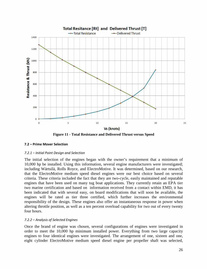
The total vessel resistance was calculated in order to determine the resistive forces of the hull and appendages at all plausible speeds. These values would later be used to calculate the speed and available thrust of the vessel. Using HydroComp NavCad 2007, the vessel’s bare hull and appendage drag were determined along with an eight percent preliminary design margin and Table 21 illustrates the average percentage of drag associated with the hull and the appendages at all speeds. NavCad allowed for all appendages to modeled, such as the skeg, Kort nozzles, shafting, struts, bow thruster opening, ice knives and rudders. Predictive equations such as Holtrop’s 1984 Method and the ITTC prediction line were also used. The plot in Figure 11 represents the total resistance and thrust of the vessel versus speed. The thrust of the vessel will be further explained in the propulsion portion of this section. The intersection of the lines in this plot indicates the operating point where vessel thrust equals vessel resistance and thus the location of the vessel’s top speed of 16 knots.
Vessel Speed Bare Hull Drag (%) Appendage and Wind Drag (%) 2 - 16 knots 91% 9%
Table 21 - Percentage of Total Drag
26
Figure 11 - Total Resistance and Delivered Thrust versus Speed
7.2 – Prime Mover Selection
7.2.1 – Initial Point Design and Selection
The initial selection of the engines began with the owner’s requirement that a minimum of 10,000 hp be installed. Using this information, several engine manufacturers were investigated; including Wärtsilä, Rolls Royce, and ElectroMotive. It was determined, based on our research, that the ElectroMotive medium speed diesel engines were our best choice based on several criteria. These criteria included the fact that they are two-cycle, easily maintained and reputable engines that have been used on many tug boat applications. They currently retain an EPA tier two marine certification and based on information received from a contact within EMD, it has been indicated that with several easy, on board modifications that will soon be available, the engines will be rated as tier three certified, which further increases the environmental responsibility of the design. These engines also offer an instantaneous response in power when altering throttle position, as well as a ten percent overload capability for two out of every twenty four hours.
7.2.2 – Analysis of Selected Engines
Once the brand of engine was chosen, several configurations of engines were investigated in order to meet the 10,000 hp minimum installed power. Everything from two large capacity engines to four identical engines were investigated. The arrangement of one, sixteen and one, eight cylinder ElectroMotive medium speed diesel engine per propeller shaft was selected,

27
delivering a total of 10,570 hp between all four engines. Table 22 and Table 23 illustrate the characteristics of each selected engine. A detailed analysis of the fuel consumption of the engines can be found in Appendix F – Powering Specifications. There is enough lube oil stored on board to lubricate the prime movers for 3,360 hours of continuous operation in order to save time at port when re-fueling the vessels.
MCREngine 1,312 kW (1,760 BHP) @ 800 rpm (kW) Cylinders 8 Fuel Consumption Rate (t/kW*hr) 0.00020438 Brand ElectroMotive Model EMD 8-710GC-T2
Table 22 – 8 Cylinder Engine Characteristics
MCREngine 2,629 kW (3,525 BHP) @ 800 rpm (kW) Cylinders 16 Fuel Consumption Rate (t/kW*hr) 0.00019921 Brand ElectroMotive Model EMD 16-710GC-T2
Table 23 – 16 Cylinder Engine Characteristics Figure 12 illustrates the layout of the selected engines. The theory behind the layout displayed in this rendered figure is so that the fire pumps can be powered mechanically with the two eight cylinder engines, leaving the sixteen cylinder engines to provide propulsion power during fire fighting exercises. Also, during towing of small barges or vessels or during general maneuvering exercises where the entire 10,570 hp installed is not needed, the eight cylinders can be powered down, reducing the overall fuel consumption and extending the life of the engines. This layout is feasible by using a clutch system, along with the double input reduction gears going to the propeller shafts, and the single reduction gears going to the fire pumps from the eight cylinder engines. Appendix F – Powering Specifications contains more detailed information on these engines.

28
Figure 12 - Engine Layout Rendering
7.3 – Propulsion Design
The propeller design in the particular case of a tug style vessel is fairly difficult because it is necessary to maximize thrust at low speeds while also maximizing over all vessel speed for quick response time to salvage operations. This was done using NavCad 2007 which led to the design of two controllable pitch propellers housed within ka-19a Kort nozzles to maximize thrust. Prediction equations such as Holtrop’s 1984 Method and Keller’s Cavitation equation were utilized. The Kort nozzles and propeller shafting will be ice strengthened and protected by ice knives on the back side for reverse conditions. The final characteristics of the counter rotating propeller design are displayed in Table 24 and a rendering of the propeller design can be seen in Figure 13.
Characteristic Value Quantity 2 DP 4.0 m P controllable AE/AO 0.85 RPM 188 rpm Maximum Efficiency 46 %
Table 24 – Propeller Characteristics

29
Figure 13 - Propeller and Kort Nozzles
The reason for the fairly low efficiency is due to the optimization of thrust and top speed. The benefits of having one of these, causes downfalls to having the other. Figure 14 illustrates the cavitation of the propeller blades at vessel speeds up to sixteen knots. It is relevant to note that at low speed, towing and bollard pull condition, the cavitation is under 5%, thus lowering propeller damage. Figure 15 illustrates the propeller efficiency, torque and thrust coefficients. The propeller efficiency is highest at thirteen knots, a typical port to port maneuvering speed.
Figure 14 - Cavitation versus Vessel Speed

30
Figure 15 - Propeller Coefficients versus Vessel Speed
7.4 – Towing and Bollard Pull
With the propulsion system preliminarily designed, its capabilities in towing and bollard pull were explored in order to confirm that it was a feasible proposal. The missions of the tug, which are reliant on the propulsion system, include salvage, barge towing and ship assist missions. It was determined that our propulsion system delivered 129.7 tons force of bollard pull at the zero speed condition, which was higher than the initial 115 tons force that was initially estimated. To put this into a physical perspective, it was calculated that there was an available thrust of roughly 789 kN at 7 knots. Analyzing the modern day 12,000 mT barge in Figure 16, with the characteristics listed below, it was determined to have 615 kN of resistance from friction, wave and wind drag terms. The available thrust is greater than the resistance of the barge, so Sea Tools can confidently declare that this design is able to tow this typical barge with a 22% margin to account for more adverse conditions. Appendix G – Machinery Specifications contains more detailed information about this barge.

31
Figure 16 - 12,000 mt Barge (380' x 100') with 11' Draft
7.5 – Electrical Power Estimation
The electrical load of the design was initially estimated as the sum of the following machinery and controls plus a twenty percent preliminary design margin: crane, winch, hotel/deckhouse service, fire monitor controls, machinery pumps and controls, bow thruster, etc.
7.6 – Generator Selection
It is recommend that the installation of two 1,550 kW Caterpillar 3512C generators is reasonable in order to design in redundancy in case of failure and to alternate between generators to increase the life cycle of each. Also, these generators may both need to be used in situations involving salvage operations and the use of the 500 kW bow thruster. The Caterpillar C6.6 ACERT emergency generator was selected to ensure all communication and on board fire suppressant systems are available in case of emergency or damage to the vessel or primary power generators. The characteristics of the service loads versus installed generator power outputs are displayed in Table 25. Appendix F – Powering Specifications contains more detailed information on these generators.
Required (kW) Installed (kW) Average at Sea Service Load 750 3,100 Maximum at Sea Service Load 1,525 3,100 Emergency Power 153 158
Table 25 – Generator Characteristics 7.7 – One Line Diagram
Figure 17 illustrates the electrical configuration on board the vessel and shows the availability of 440, 240 and 120 volt applications for select machinery and accommodations throughout the vessel. This electrical design proposal allows for all current machinery to be operated efficiently, as well as allowing for any future machinery additions to easily be installed. Appendix F – Powering Specifications contains a larger detailed figure of the one line diagram.

32
Figure 17 - One-Line Diagram

33
8.0 – Intact and Damage Stability
Intact and damaged stability of the Sea Tools tug determined whether or not the ship was stable enough to pass requirements set forth in the Code of Federal Regulations (CFR).
8.1 – Intact Stability
Intact stability of the vessel was analyzed using the HECSALV stability suite and compared to CFR requirements.
8.1.1 – U.S. Coast Guard Wind Heel Requirements The U.S. Coast Guard requires a minimum GMT based on a ship’s profile area above water on which beam winds could act and heel the ship. The “USCG Wind Heel GMT” spreadsheet was used to determine minimum value to be 0.62 m. The Sea Tools tug’s GMT is 3.19 m, which clearly passes this requirement. The “USCG Wind Heel GMT” spreadsheet has been included in Appendix J – Intact Stability.
8.1.2 – Towing Stability Criteria The CFR mandates certain stability requirements in the towing condition. A choice is given in the CFR of meeting a minimum metacentric height (GM) or passing requirements regarding the heeling arm and righting arm curves. The GM height requirement was chosen as the towing stability criterion the Sea Tools tug was to pass. The equation found in Figure 18 is provided and the indicated inputs were used to calculate the minimum required GM. The equation derives from the tug having its rudders full turned at full speed while not moving forward which creates the largest heeling moment on the tug.
23
f
( )( ) ( )( )
( )B
N P D s hGMK×
=∆
N (number of propellers) 2 P (shaft power per shaft in kilowatts) 3941 D (propeller diameter in meters). 4.5 s (fraction of the propeller circle cylinder intercepted when rudder turned 45 degrees from the vessel's centerline)
0.719857
h (vertical distance from propeller shaft centerline at rudder to towing bitts in meters)
6.83
Δ (displacement in metric tons) 2936 f (minimum freeboard along the length of the vessel in meters) 1.859 B (molded beam in meters) 15 K=13.93 in metric units 13.93
Figure 18 - Towline Pull Criterion The calculated minimum GM requirement for the Sea Tools tug was discovered to be 1.32 m. The Sea Tools tug’s GMT of 3.19 m passes this requirement.
8.1.3 – Topside Icing Specific requirements regarding icing of the topsides of an uninspected tug do not exist however this was a case that Sea Tools wished to consider for the tug because of its Arctic operation. The CFR topside icing requirements for fishing vessels was used to calculate the effects of icing on the Sea Tools tug. The icing requirements are applicable for vessels operating between 42˚

34
North latitude and 66˚30’ North latitude between November 15 and April 15. 30 kg/m2 (corresponding to 1.3”) of ice and 15 kg/m2 (corresponding to 0.65”) of ice is to be used for horizontally and vertically projected surfaces, respectively. This calculation indicated that full topside icing would result in 15.7 mt of ice added to the vessel. Adding this mass to our weights estimation and recalculating the hydrostatics determined that the GMT of the vessel reduces to 3.16 m, which still passes all of the CFR mandated requirements.
8.1.4 – Cross Curves of Stability HECSALV was used to generate the cross curves of stability for the Sea Tools tug and then used to create the GZ curves at the full load condition. The GZ curves are presented in Figure 19. The max GZ of 1.22 m occurs at a heel angle of 34.9˚.
Figure 19 – GZ Curves
8.1.5 – Bonjean Curves Bonjean curves present station areas at different mean drafts. HECSALV was used to generate these curves and are presented in Figure 20.
0.0
0.2
0.4
0.6
0.8
1.0
1.2
1.4
0 20 40 60 80 100
GZ
(m)
Heel Angle (deg)
GZ Curve Max GZ

35
Figure 20 – Bonjean Curves
8.2 – Damaged Stability
Requirements governing compartment flooding survival for uninspected tugs does not exist, however safe operation in damaged conditions was a primary concern for the Sea Tools tug design. One compartment flooding for all compartments was determined to be a necessary requirement in addition to two compartment flooding in the two bow compartments. The MARAD Design Letter 3 was used as damaged stability to determine if the Sea Tools tug would remain stable in each damaged condition. These criteria were selected because they are relatively conservative compared to other rule sets which could have been used for this vessel. The rules are presented in Table 26.
GZ Max Heel GM 20˚ positive range, 0.1 m minimum 15˚ Positive
Table 26 - MARAD Design Letter 3 Damaged Stability Criterion The Damaged Stability part of the HECSALV program suite was used to test eight different compartment flooding cases. Initially, the tug failed when the engine room was flooded. The bulkheads were re-spaced to decrease the volume of the engine room. Compartment one is the forward most compartment on the vessel. A summary of each damage stability case is shown in Table 27. All of the damaged cases with their complete results and diagrams are included in Appendix K – Damaged Stability.

36
Damaged Equilibrium
# Draft Status Damage AngMax GZ (deg)
IntGM (m)
Area (m-rad)
LimitAngle (deg)
AngE (deg)
MaxGZ M
Range (deg)
Pass/Fail
1 1 1 1 15.3 0.308 0.0215 22.9 0 0.100 22.9 Pass
2 1 1 2 12.9 0.519 0.0231 21.4 0 0.100 21.4 Pass
3 1 1 4 10.8 0.792 0.0231 20.6 0 0.100 20.6 Pass
4 1 1 8 10.0 1.073 0.0288 20.0 0 0.134 20.0 Pass
5 1 1 10 9.9 1.296 0.0348 20.0 0 0.164 20.0 Pass
6 1 1 12 10.5 0.822 0.0234 20.0 0 0.107 20.0 Pass
7 1 1 13 14.7 0.343 0.0202 21.5 0 0.100 21.5 Pass
8 1 1 1,2 11.9 0.577 0.0226 20.7 0 0.100 20.7 Pass
Table 27 – Damage Stability Results

37
9.0 – Midship Analysis
The midship cross section of the vessel was structurally analyzed to determine if the ship passes the regulations set forth by the American Bureau of Shipping (ABS).
9.1 – ABS Regulations
ABS regulations state that the section modulus of the midship section should be larger than the greater result of equations one and three. The equations used to calculate the requirements are provided below.
2min 1 2 ( 0.7)bSM C C L B C= + Equation 1
1 0.0451 3.65C L= + Equation 2
2 0.01C = Equation 3 /t pSM M f= Equation 4
t SW WSM M M= + Equation 5 Maximum Still Water Bending MomentSWM = Equation 6
2 31 1 ( 0.7) 10WS bM k C L B C −= − + ⋅ Equation 7
2 32 1 10WH bM k C L BC −= ⋅ Equation 8
1 110k = Equation 9
2 190k = Equation 10 217.5 /pf t cm= Equation 11
The results from these calculations are listed in Table 28. These values were used in the analysis of the midship section.
Variable Result Units
Mws -56,000 kN-m Mwh 44,650 kN-m
Msw 31.41 kN-m
SMmin 3202.0 cm2-m
SM 16,390 cm2-m
Table 28 – ABS Longitudinal Strength Calculations
9.2 – Moment and Shear Diagram
The moment and shear diagrams were generated using Hydromax. The weights curves were used in previously described calculations to confirm that the vessel adhered to ABS regulation. The maximum bending moments are presented in Table 29.
Condition Max Moment
Full Departure 3689 mt-m %50 Fuel 3110 mt-m
%10 Fuel 3270 mt-m
Table 29 - Maximum Bending Moments

38
The maximum bending moment was developed in the Full Departure condition and using Hydromax, the net load, shear, and bending moment distributions were plotted. The complete results from Hydromax are included in Appendix M – Structural Calculations as well as the weights estimation spreadsheets.
Figure 21 – Load Distribution for the Full Load Condition
9.3 – Midship Analysis
The utilization of a midship section analysis spreadsheet was used in conjunction with the section modulus and moment of inertia values calculated from the ABS requirements to determine the characteristics of the vessel’s midship section. Because of how the vessel was strengthened, the minimum SM requirement of 3,202 cm2-m was met easily. This spreadsheet is included in Appendix M – Structural Calculations and a table of the midship section properties is included in Table 30.
ABS Required Actual Units
SM deck 3202 29,220 cm2-m SM bottom 3202 16,390 cm2-m
Table 30 – Midship Section Strength Properties
39
10.0 Structural Analysis
The structural analysis of the vessel was performed considering two regulatory sources of input. While the vessel will be classified by the American Bureau of Shipping, all Ice strengthening aspects of the vessel were designed considering the “Finnish-Swedish Ice Class Rules”. These rules were selected based on their relative strictness when compared to ABS, and the structural safety they will provide. Rules from the American Bureau of Shipping found in “Rules for Building and Classing Steel Vessel Under 90 Meters in Length” were referenced for all other aspects of the design. A summary of plate thicknesses can be found below.
10.1 Ice Strengthened Regions
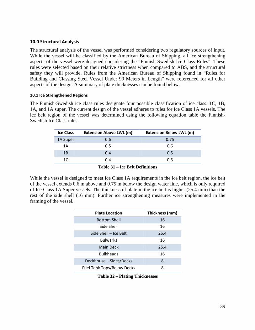
The Finnish-Swedish ice class rules designate four possible classification of ice class: 1C, 1B, 1A, and 1A super. The current design of the vessel adheres to rules for Ice Class 1A vessels. The ice belt region of the vessel was determined using the following equation table the Finnish-Swedish Ice Class rules.
Ice Class Extension Above LWL (m) Extension Below LWL (m)
1A Super 0.6 0.75 1A 0.5 0.6
1B 0.4 0.5
1C 0.4 0.5
Table 31 – Ice Belt Definitions While the vessel is designed to meet Ice Class 1A requirements in the ice belt region, the ice belt of the vessel extends 0.6 m above and 0.75 m below the design water line, which is only required of Ice Class 1A Super vessels. The thickness of plate in the ice belt is higher (25.4 mm) than the rest of the side shell (16 mm). Further ice strengthening measures were implemented in the framing of the vessel.
Plate Location Thickness (mm)
Bottom Shell 16 Side Shell 16
Side Shell – Ice Belt 25.4
Bulwarks 16
Main Deck 25.4
Bulkheads 16
Deckhouse – Sides/Decks 8
Fuel Tank Tops/Below Decks 8
Table 32 – Plating Thicknesses

40
10.2 Framing
Transverse framing was selected for the vessel because of its relatively short length and the simplicity of construction that transverse framing offers. Unless stated otherwise, all framing in the vessel was spaced at 0.46 m. This section will discuss the structural members of each part of the vessel. All structural calculations can be found in Appendix M – Structural Calculations.
Location Classification Society Used
Required SM (m*cm2)
Actual SM (m*cm2)
Bottom Frame ABS 1018 1140
Side Frame FIN 1133 1140
Deck Frames ABS 702 747
Deck Girders ABS 4162 4553
Bulkhead Girder ABS 69 87
Bulkhead Stiffener ABS 328 352
Superstructures - Side ABS 26 38
Superstructure – Deck Frames ABS 696 761
Superstructure – Deck Girder ABS 515 564
Table 33 – Required and Actual Section Moduli
Angle bars were used as stiffening members in all locations except the deckhouse. Angle bars were selected over t-bars because of lower cost and ease of production. In the deckhouse of the vessel it was feasible to select unobtrusive flat plate bars with an adequate section modulus. In future design iterations the sizing of these bars will be investigated with special attention paid to the weight of flat bar stiffeners and the space that could be saved if angle or t-bars were selected instead.
Location L (cm) W (cm) t (cm) Steel Strength
Bottom Frame 20 20 3 Normal Side Frame 20 20 3 High
Deck Frames 20 15 2.5 Normal
Deck Girders 71 56 2.5 Normal
Bulkhead Girder 8 8 1 Normal
Bulkhead Stiffener 15 15 1 Normal
Superstructures - Side 10 --- 1 Normal
Superstructure –Deck Frames 20 15 2 Normal
Superstructure –Deck Girder 40 --- 2.5 Normal
Table 34 – Stiffener Sizing The bottom and side frames of the vessel have the largest required section moduli of all structural members below deck. Because of the similar nature of the bottom and side framing requirements, angle bars with identical geometry were selected for these structural members. It should be noted that the side frame requirement assumes that the frames be constructed out of a

41
high strength steel of yield stress greater than 315 𝑁𝑁
𝑚𝑚𝑚𝑚2. Because the side frames of the vessel
will be constructed out of high strength steel, longitudinal strengthening members will not be necessary on the side shell. Another benefit of using such structurally sound side frames is that machinery stress, such as moments generated by the winches or crane, will not cause the failure of any structural members. The bulkheads of the vessel will also be structurally sound. All bulkheads will be constructed out of 16 mm thick steel and fitted with vertical stiffeners sized to adequately strengthen the deepest bulkhead of the vessel. Where necessary, a horizontal deck girder will be installed such that no vertical span of length 4.5 m or more will be horizontally unsupported. The deep tank structural requirements were also analyzed. It was determined that the existing bulkhead plating and stiffeners would adequately strengthen the deep tanks, and that no additional structural members would be required. The deck of the vessel will be made out of inch thick steel and strengthened by both transverse deck frames and two longitudinal deck girders spaced evenly across the deck. The high section modulus requirement of the longitudinal deck girders is a result of the bulkhead spacing of the vessel. Two deck girders were selected to reduce the sizing requirements of the transverse deck frames. The size of the deckhouse necessitated that the transverse deck frames in the deckhouse be sized similarly to the deck frames of the main deck. These deck frames were joined to relatively small deckhouse side frames to complete the deckhouse framing system. As previously discussed, a flat bar longitudinal deck girder was fitted below each deck level, and the geometry of this girder will be investigated in the future.

42
11.0 – Maneuvering Analysis
The University of Michigan’s Maneuvering Prediction Program (MPP) was used to determine the maneuvering characteristics of the Sea Tools tug and to size its rudders.
11.1 – Initial Sizing
MPP requires an initial guess for the size of the rudder and iterations must be performed to meet IMO maneuvering regulations. The initial input for the size of one rudder was derived from the equation below.
Equation 12
The estimated rudder area was calculated to be 8.5 m2.
11.2 – Maneuvering Prediction Program
Several iterations were necessary to find an appropriate rudder size. The final rudder area was determined to be 11.1 m2. For a rudder turning ability of 35˚, a ship is specified to have an advance of less than 4.5LBP, a tactical diameter of less than 5LBP, a Clarke’s turning index greater than 0.4, and a Linear Dynamic Stability Criterion greater than zero. The maneuvering requirements and results for the tug are presented in Table 35. Results from MPP are provided in Appendix H – Maneuvering.
Required Calculated Advance (m) <295.2 236.1 Tactical Diameter (m) <328 312.8 Clarke’s Turning Index >0.4 11.3 Linear Dynamic Stability >0.0 0.00041
Table 35 – Maneuvering Analysis
11.3 – Bow Thruster
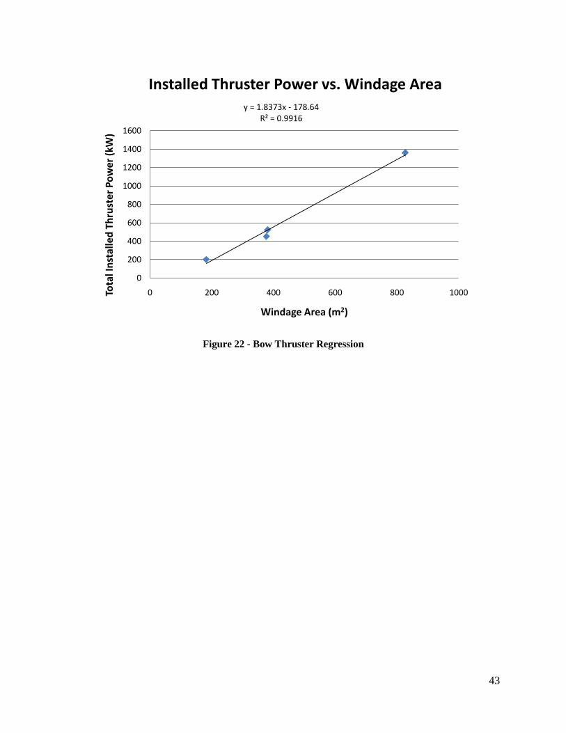
The bow thruster for the Sea Tools tug was selected by performing a regression analysis on similar tugs and their projected sail area (Figure 22). Based on the Sea Tools tug’s sail area of 325 m2, it was determined that the bow thruster should have an installed power of 502 kW (including a 20% margin). A 614 kW Wartsila and 530 kW Schottel bow thruster were both examined for selection. The Schottel thruster was chosen because its power was closer to the estimated power requirement and because of lower weight and therefore lower expected cost. Thruster details are provided in Appendix H – Maneuvering.
2
1 25100rLT BA
L = +
43
Figure 22 - Bow Thruster Regression
y = 1.8373x - 178.64R² = 0.9916
0
200
400
600
800
1000
1200
1400
1600
0 200 400 600 800 1000Tota
l Ins
talle
d Th
rust
er P
ower
(kW
)
Windage Area (m2)
Installed Thruster Power vs. Windage Area
44
12.0 – Seakeeping Analysis
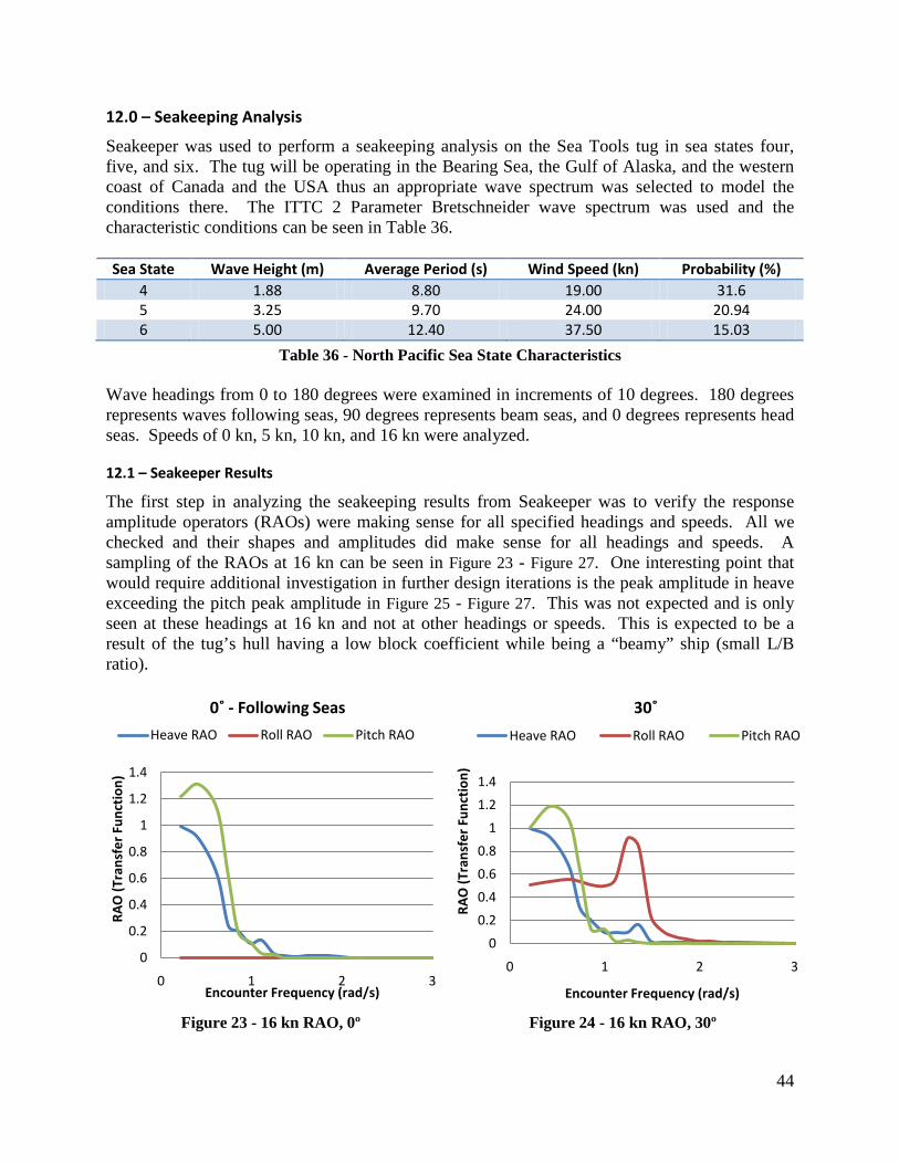
Seakeeper was used to perform a seakeeping analysis on the Sea Tools tug in sea states four, five, and six. The tug will be operating in the Bearing Sea, the Gulf of Alaska, and the western coast of Canada and the USA thus an appropriate wave spectrum was selected to model the conditions there. The ITTC 2 Parameter Bretschneider wave spectrum was used and the characteristic conditions can be seen in Table 36. Sea State Wave Height (m) Average Period (s) Wind Speed (kn) Probability (%)
4 1.88 8.80 19.00 31.6 5 3.25 9.70 24.00 20.94 6 5.00 12.40 37.50 15.03
Table 36 - North Pacific Sea State Characteristics Wave headings from 0 to 180 degrees were examined in increments of 10 degrees. 180 degrees represents waves following seas, 90 degrees represents beam seas, and 0 degrees represents head seas. Speeds of 0 kn, 5 kn, 10 kn, and 16 kn were analyzed.
12.1 – Seakeeper Results
The first step in analyzing the seakeeping results from Seakeeper was to verify the response amplitude operators (RAOs) were making sense for all specified headings and speeds. All we checked and their shapes and amplitudes did make sense for all headings and speeds. A sampling of the RAOs at 16 kn can be seen in Figure 23 - Figure 27. One interesting point that would require additional investigation in further design iterations is the peak amplitude in heave exceeding the pitch peak amplitude in Figure 25 - Figure 27. This was not expected and is only seen at these headings at 16 kn and not at other headings or speeds. This is expected to be a result of the tug’s hull having a low block coefficient while being a “beamy” ship (small L/B ratio).
Figure 23 - 16 kn RAO, 0º
Figure 24 - 16 kn RAO, 30º
0
0.2
0.4
0.6
0.8
1
1.2
1.4
0 1 2 3
RAO
(Tra
nsfe
r Fu
ncti
on)
Encounter Frequency (rad/s)
0˚ - Following Seas
Heave RAO Roll RAO Pitch RAO
0
0.2
0.4
0.6
0.8
1
1.2
1.4
0 1 2 3
RAO
(Tra
nsfe
r Fu
ncti
on)
Encounter Frequency (rad/s)
30˚
Heave RAO Roll RAO Pitch RAO

45
Figure 25 - 16 kn RAO, 90º
Figure 26 - 16 kn RAO, 140º
Figure 27 - 16 kn RAO, 180º
The next step in analyzing the Seakeeper data was to examine the RMS values of heave, roll, and pitch at all headings, speeds, and sea states. Plots of the RMS heave, roll, and pitch values at 16 kn are presented in Figure 28, Figure 29, and Figure 30. It was seen that the motions appear as expected for the given sea state and heading and it should be noted that the consistency of data was also verified at the other speeds analyzed. Subsequent design iterations should use an alternative seakeeping analysis to verify the results found here. The complete Seakeeper results are included in Appendix L – Seakeeping Results.
0
0.5
1
1.5
2
2.5
3
0 1 2 3
RAO
(Tra
nsfe
r Fu
ncti
on)
Encounter Frequency (rad/s)
90˚ - Beam SeasHeave RAO Roll RAO Pitch RAO
0
0.5
1
1.5
2
0 1 2 3
RAO
(Tra
nsfe
r Fu
ncti
on)
Encounter Frequency (rad/s)
140˚Heave RAO Roll RAO Pitch RAO
0
0.2
0.4
0.6
0.8
1
1.2
1.4
1.6
1.8
0 1 2 3
RAO
(Tra
nsfe
r Fu
ncti
on)
Encounter Frequency (rad/s)
180˚ - Head SeasHeave RAO Roll RAO Pitch RAO

46
Figure 28 - Heave Response
Figure 29 - Roll Response
Figure 30 - Pitch Response
00.20.40.60.8
11.21.41.6
0 50 100 150 200
Hea
ve A
mpl
itud
e (m
)
Heading (deg)
Heave RMS, 16 kts ss4 ss5 ss6
012345678
0 50 100 150 200
Roll
Am
plit
ude
(deg
)
Heading (deg)
Roll RMS, 16 kts ss4 ss5 ss6
0
0.5
1
1.5
2
2.5
3
3.5
0 50 100 150 200
Roll
Am
plit
ude
(deg
)
Heading (deg)
Pitch RMS, 16 kts ss4 ss5 ss6

47
12.2 – Natural Periods
The RAO graphs produced by Seakeeper were analyzed and the natural frequencies found for each response. The natural periods for each response were then found and are listed in Table 37.
Degree of Freedom Natural Period (s)
Heave 5.7 Roll 6.3
Pitch 10.1
Table 37 - Natural Periods
12.3 – Working Condition Analysis
The specified owner’s requirements dictated that the tug be able to operate in sea state six and at the full speed of 16 kn. In order to validate workable conditions on the tug boat, it was necessary to look at the Motion Induced Interruptions (MIIs) occurring at critical locations on the vessel. The red markers seen in Figure 31 show the two locations analyzed, the wheel house on centerline and the tow winch controls, 3 m starboard of centerline.
Figure 31 - Critical MII Locations
Seakeeper calculates the accelerations at those locations and determines how many times per hour a person would be interrupted during their work due to the local accelerations. All speeds and headings were analyzed and the worst MII cases are shown in Table 38.
Motion-Induced Interruptions per hour
SS4 SS5 SS6 Wheelhouse 5.6 18.0 16.5 Work deck 8.2 19.4 18.3
Table 38 - Worst Cast MII Results As highlighted in red, the maximum number of MIIs per hour is about 20, which falls between the lowest two severity ranges shown in Table 39. From this analysis, it has been determined

48
that a salvage crew will have no problem operating the Sea Tools tug at full speed during sea state six.
MII Risk Levels
Severity MII Risk Level MII per hour
1 Possible 6 2 Probable 30 3 Serious 90 4 Severe 180 5 Extreme 300
Table 39 – MII Risk Levels The Motion Sickness Incidence analysis performed by Seakeeper did indicate that an untrained, non-sailor would be subject to 10% probability of sea sickness in under 30 minutes during sea states five and six at a full speed of 16 kn. However, contacts in the U.S. Coast Guard have indicated that this will not be an issue for a seasoned salvage tug crew.
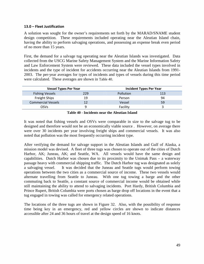
49
13.0 – Fleet Justification
A solution was sought for the owner’s requirements set forth by the MARAD/SNAME student design competition. These requirements included operating near the Aleutian Island chain, having the ability to perform salvaging operations, and possessing an expense break even period of no more than 15 years. First, the demand for a salvage tug operating near the Aleutian Islands was investigated. Data collected from the USCG Marine Safety Management System and the Marine Information Safety and Law Enforcement System were reviewed. These data included the vessel types involved in incidents and the type of incident for accidents occurring near the Aleutian Islands from 1991-2003. The per-year averages for types of incidents and types of vessels during this time period were calculated. These averages are shown in Table 40.
Vessel Types Per Year Incident Types Per Year Fishing Vessels 229 Pollution 113 Freight Ships 19 Person 94
Commercial Vessels 12 Vessel 59 OSVs 9 Facility 3
Table 40 - Incidents near the Aleutian Island It was noted that fishing vessels and OSVs were comparable in size to the salvage tug to be designed and therefore would not be an economically viable source . However, on average there were over 30 incidents per year involving freight ships and commercial vessels. It was also noted that pollution was the most frequently occurring incident type. After verifying the demand for salvage support in the Aleutian Islands and Gulf of Alaska, a mission model was devised. A fleet of three tugs was chosen to operate out of the cities of Dutch Harbor, AK; Juneau, AK; and Seattle, WA. All vessels would have the same design and capabilities. Dutch Harbor was chosen due to its proximity to the Unimak Pass – a waterway passage heavy with commercial shipping traffic. The Dutch Harbor tug was designated as solely a salvaging vessel. It was decided that the Juneau and Seattle tugs would perform towing operations between the two cities as a commercial source of income. These two vessels would alternate travelling from Seattle to Juneau. With one tug towing a barge and the other commuting back to Seattle, a constant source of commercial income would be obtained while still maintaining the ability to attend to salvaging incidents. Port Hardy, British Columbia and Prince Rupert, British Columbia were ports chosen as barge drop off locations in the event that a tug engaged in towing was called for emergency related operations. The locations of the three tugs are shown in Figure 32. Also, with the possibility of response time being key in an emergency, red and yellow circles are shown to indicate distances accessible after 24 and 36 hours of travel at the design speed of 16 knots.

50
Figure 32 - Tug Fleet Locations

51
14.0 Economic Analysis
The economics of the tug fleet were analyzed and refined throughout the design of the vessel. With the 15-year break even requirement driving the analysis, the expenses incurred from crew costs, build costs, and operational costs were examined. Through a contact within the salvaging industry, estimates for 12-man crew costs were provided. These crew costs appear in Table 41.
Crew Cost Per Day Crew Cost Per Year Crew Cost Over 15 years
Captain $650 $237,250 $3,558,750 Mates (3) $1,620 $591,300 $8,869,500
Chief Engineer $550 $200,750 $3,011,250 QMEDs (2) $800 $292,000 $4,380,000
AB Deckhands (5) $1,550 $565,750 $8,486,250 25% Payroll Tax $1,293 $471,763 $7,076,438
15% Admin Expense $776 $283,058 $4,245,863 Total Crew Costs $7,238 $2,641,870 $39,628,050
Table 41 - Crew Cost Breakdown The contact also provided a build cost estimate of $20 million. To make this estimate more conservative, it was increased to $25 million. In addition, an 80% loan with a 4% interest rate compounded annually for 15 years was applied to the $25 million build cost estimate. These figures, as well as the accumulated interest and total build cost, are presented in Table 42.
Build Cost
Build Cost $25,000,000 80% Build Cost Loan $20,000,000
Interest Rate 4% Accumulated Interest $1,798,822
Total Build Cost $26,798,822
Table 42 - Build Cost Breakdown Lastly, a preliminary estimate for the operational costs was provided by the industry contact. These costs are displayed in Table 43.
Per Day Per Year Over 15 Years
Operational Costs $4,762 $1,738,130 $26,071,950
Table 43 - Operational Cost Breakdown The total preliminary costs for the tug design and the three tug fleet over the first 15 years of operation are presented in Table 44.
15 Year Expense Totals 15 Year Total Tug Expenses $92,498,822
15 Year Total Fleet Expenses $277,496,466
Table 44 - 15 Year Expense Summary

52
With the preliminary expenses established, estimates were made for the possible returns through salvaging operations, fire fighting, and other emergency related missions. The industry contact estimated that a gross income of $8 million can be received from a single large salvaging job. A more conservative estimate of $5 million per salvage job each year per tug was used. Based off of this estimate, the returns used for the preliminary economics of the tug fleet appear in Table 45.
Per Year Over 15 Years Dutch Harbor $5 million $75 million
Juneau $5 million $75 million Seattle $5 million $75 million Total $15 million $225 million
Table 45 - Salvage Revenue Throughout the design, as machinery was selected and the missions to be performed were developed further, the economic analysis of the fleet was refined. The same estimates used for the preliminary twelve man crew and build costs were used for the additional iterations of the economic analysis. Using specific fuel consumptions, average fuel prices, and time at sea estimates, the operational costs were updated. The specific fuel consumptions used appear in Table 46, and the average fuel prices, collected by the Fisheries Economics Data Program, are shown in Table 47.
8 Cylinder 16 Cylinder
SFC (lb/bhp-hr) 0.336 0.3275 Consumption Rate (lb/hr) 554.4 1195.4
Volume Consumption Rate (gal/day) 1874.03 4040.70
Table 46 - Specific Fuel Consumption
#2 Marine Diesel Fuel Prices
2010 Average Alaskan Port Fuel Prices $2.91 2010 Average Washington Port Fuel Prices $2.65
Average of 2010 Alaskan and Washington Port Fuel Prices $2.78
Table 47 - Average Fuel Prices These data were combined with time at sea estimates. The time at sea estimates were developed by considering that the Dutch Harbor tug would not tow and would, therefore, spend less time at sea per year. While operating at sea, it was assumed that all four of a tug’s engines would be operating at 850 rpm. In addition, the average 2010 port fuel prices for #2 marine diesel fuel in Alaska and Washington were averaged for the Juneau and Seattle tugs. This was done because the tugs would be towing between the two states and might refuel in either Alaska or Washington. The fuel consumption summaries for each tug appear in Table 48, Table 49 and Table 50.
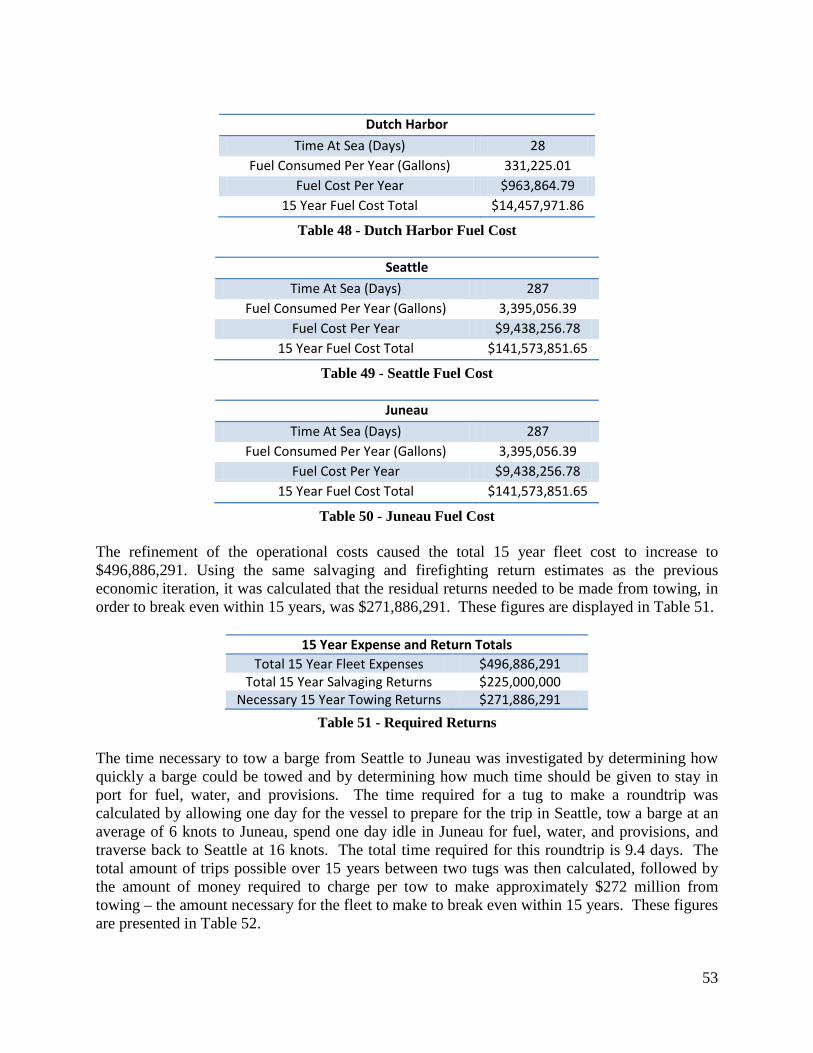
53
Dutch Harbor
Time At Sea (Days) 28 Fuel Consumed Per Year (Gallons) 331,225.01
Fuel Cost Per Year $963,864.79 15 Year Fuel Cost Total $14,457,971.86
Table 48 - Dutch Harbor Fuel Cost
Seattle
Time At Sea (Days) 287 Fuel Consumed Per Year (Gallons) 3,395,056.39
Fuel Cost Per Year $9,438,256.78 15 Year Fuel Cost Total $141,573,851.65
Table 49 - Seattle Fuel Cost
Juneau
Time At Sea (Days) 287 Fuel Consumed Per Year (Gallons) 3,395,056.39
Fuel Cost Per Year $9,438,256.78 15 Year Fuel Cost Total $141,573,851.65
Table 50 - Juneau Fuel Cost The refinement of the operational costs caused the total 15 year fleet cost to increase to $496,886,291. Using the same salvaging and firefighting return estimates as the previous economic iteration, it was calculated that the residual returns needed to be made from towing, in order to break even within 15 years, was $271,886,291. These figures are displayed in Table 51.
15 Year Expense and Return Totals Total 15 Year Fleet Expenses $496,886,291
Total 15 Year Salvaging Returns $225,000,000 Necessary 15 Year Towing Returns $271,886,291
Table 51 - Required Returns The time necessary to tow a barge from Seattle to Juneau was investigated by determining how quickly a barge could be towed and by determining how much time should be given to stay in port for fuel, water, and provisions. The time required for a tug to make a roundtrip was calculated by allowing one day for the vessel to prepare for the trip in Seattle, tow a barge at an average of 6 knots to Juneau, spend one day idle in Juneau for fuel, water, and provisions, and traverse back to Seattle at 16 knots. The total time required for this roundtrip is 9.4 days. The total amount of trips possible over 15 years between two tugs was then calculated, followed by the amount of money required to charge per tow to make approximately $272 million from towing – the amount necessary for the fleet to make to break even within 15 years. These figures are presented in Table 52.

54
Towing
Days Per Trip 9.4 Trips Per Year 39
Trips Over 15 Years (2 Tugs) 1165 Required Charge Per Tow $233,379
Total Towing Gains $271,886,291
Table 52 - Towing Summary The required freight rates of a variety of barge sizes appear in Table 53. These rates are required, in order to break even within 15 years of operating the fleet, due to losses incurred from building, operating, and manning the tugs.
RFR 4000 ton barge $58.34/ton RFR 6000 ton barge $38.90/ton RFR 8000 ton barge $29.17/ton RFR 10000 ton barge $23.34/ton RFR 12000 ton barge $19.45/ton RFR 14000 ton barge $16.67/ton RFR 16000 ton barge $14.59/ton
Table 53 - Required Freight Rate

55
15.0 – Recommendations for Future Work
While all design decisions were well-informed and made with confidence, there are some areas of the design that warrant future investigation. These areas are discussed in the body of the report as they occur, and this section will detail recommendations for future work. One area of potential concern is the ease of deep tank production. Future design iterations will investigate alternate fuel tank arrangements that would allow for easier welding during construction. The seakeeping analysis of the vessel is another area that deserves future investigation. The data obtained from Seakeeper will need future validation by other methods, and special attention will be paid to why the heave RAOs are dominating pitch RAOs at 16 knots in sea state 6 at headings between head and beam seas. A seakeeping analysis with a towing barge attached will also be necessary.
The propulsion system of the vessel could be improved in the future by performing more iterations of the propeller design to maximize, thrust, speed, and efficiency. Once completed, the system could be analyzed further and its capabilities in towing and bollard pull. It is in the opinion of Sea Tools that these further iterations will decrease the preliminary design margins and increase the towing ability of the vessel as well as the static bollard pull characteristics of the vessel. Future design iterations should also address the piping and electrical requirements for all areas of habitability. Adjustments to the arrangements may need to be made to minimize piping and electrical material in these areas. Also, more detailed estimations should be found for the returns to be made through salvaging, fire fighting, and other emergency missions. Lastly, pricing of machinery and outfitting should be considered for a more accurate build cost.

56
16.0 – Conclusion
Not only does the Sea Tools tug design satisfy all of the MARAD/SNAME student design competition requirements but also has a wide range of towing and rescue capabilities, making it a versatile design. Sea Tools Engineering is confident that the design will satisfy the need for high powered salvage tugs near the Aleutian Islands and the Gulf of Alaska. Key features of the design include highly favorable seakeeping properties, fire fighting II capabilities, and an ice strengthened hull, all of which allow the vessel to perform commercial and rescue missions in a variety of arctic water conditions.

57
Appendix A – Lines Drawing
Contents: Lines Drawing ........................................................................................................................A-1

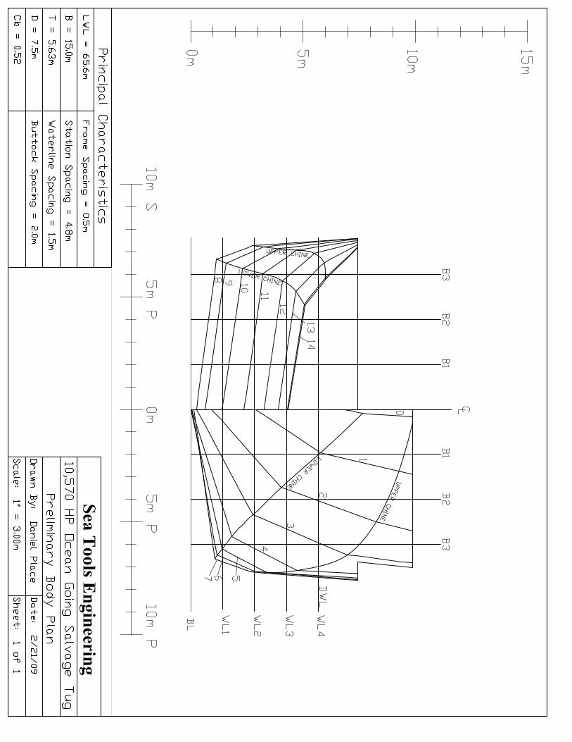

58
Appendix B – Outboard & Inboard Profiles
Contents: Outboard Profile .....................................................................................................................B-1 Inboard Profile .......................................................................................................................B-2


59
Appendix C – General Arrangements
Contents: General Arrangements 1 ........................................................................................................C-1 General Arrangements 2 ........................................................................................................C-2 General Arrangements 3 ........................................................................................................C-3 General Arrangements 4 ........................................................................................................C-4


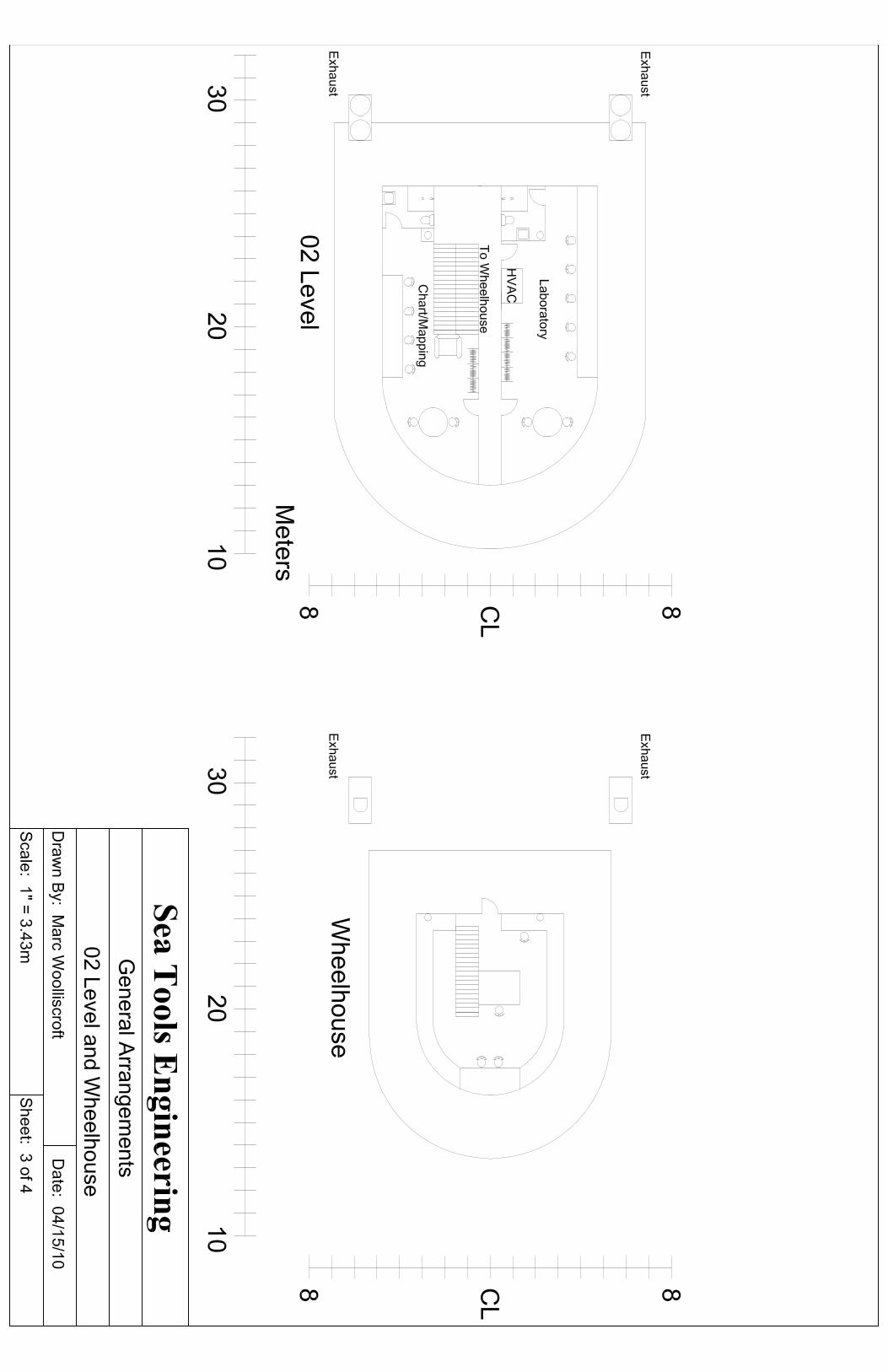


60
Appendix D – Propeller Geometry
Contents: Propeller .................................................................................................................................D-1


61
Appendix E – Structural Drawings
Contents: Deckhouse Section Layout ....................................................................................................E-1 Bulkhead Section Layout .......................................................................................................E-2 Midship Section Layout .........................................................................................................E-3


62
Appendix F – Powering Specifications
Contents: EMD Brochure .......................................................................................................................F-1 8 Cylinder Fuel Consumption ................................................................................................F-2 16 Cylinder Fuel Consumption ..............................................................................................F-3 Caterpillar 3512C Genset .......................................................................................................F-4 Caterpillar C6.6 ACERT Emergency Generator ...................................................................F-5 One Line Diagram..................................................................................................................F-6

C
M
Y
CM
MY
CY
CMY
K
PMI brochure_outside.pdf 9/10/07 10:09:15 AM

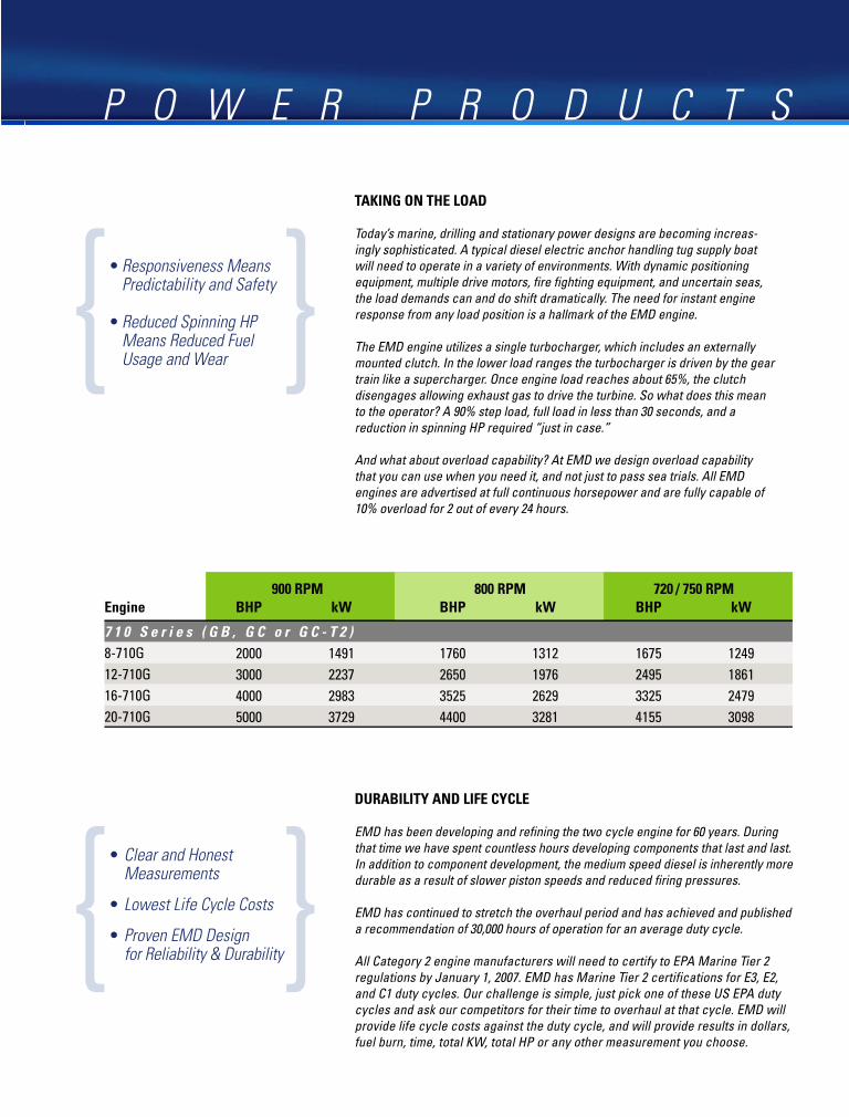
C
M
Y
CM
MY
CY
CMY
K
PMI brochure_inside.pdf 9/10/07 10:03:44 AM

C
M
Y
CM
MY
CY
CMY
K
PMI brochure_outside.pdf 9/10/07 10:09:15 AM

Fuel Consumption
Model: 8-710G7C-T2Conditions: ISO 15550 & 3046-1 Standard Reference Operating Speed: Variable
Air In Temp: 77oF (25oC) Load: VariableBarometer: 29.61 in Hg (100 kpa) Rated Speed: 900 RPMFuel S. G.: 0.855 (7.1 lbs/gal) Idle Speed: 350 RPMFuel LHV: 18360 btu/lb (42700 kJ/kg) ISO Continuous Power: 2000 BHP
Airbox Temp: 120oF (49oC) maximum ISO Overload Power: 2200 BHPBSFC Tolerance: + 5% maximum Emissions: US EPA 40 CFR 94
Emissions Tier: 2Application: Fixed Pitch Prop Propulsion EPA Duty Cycle Table: B-1
ISO Cycle: E3
Comments:Engine mounted pumps included.Horsepower / fuel consumption will vary with deviation from stated conditions.Data is provided in accordance with ISO 3046-1:2002E conditions and associated tolerances, and is intended only for purpose of comparison with competitive manufacturer engines.Electro-Motive Diesel, Inc. maintains ISO9001:CURRENT REVISION registration for its engine manufacturing and test facilities. Factory engine test data is recorded at observed site conditions in accordance with ISO9001/QMS9000 procedures.
0.330
0.340
0.350
0.360
0.370
0.380
0.390
0.400
0.410
0.420
0.430
0.440
0.450
0.460
0.470
0.480
0.490
0.500
0.510
0.520
0.530
300 400 500 600 700 800 900
Engine Speed (rpm)
Fuel
Con
sum
ptio
n (lb
/bhp
-hr)
100
300
500
700
900
1100
1300
1500
1700
1900
2100
Engi
ne P
ower
(bhp
)
Commercial_8G7C-T2_VS9_VL_B-1_E3.xls


Marine Propulsion Engines
3500C

More available power over a wider operating rangeHigh power density for continuous applications with A and B ratings at 1200, 1600, and 1800 rpm.
More sophisticated electronic control systemProvides improved engine monitoring, communication, and display capabilities. Results in easier integration with your vessel’s systems.
More flexible cooling system optionsSeparate Circuit Cooling for optimum cooling capabilities. Keel cooled options are designed for high inlet water temperatures, minimizing cooler size and installation costs.
Durable and reliableThe 3500 engine platform is a simple and proven design providing industry-leading reliability and durability.
True technical sophisticationDelivers ease of maintenance and assembly/disassembly without the need for expensive processes or tools.
Meets EPA Tier 2 Marine, EU Stage IIIA and IMO emissions regulations
THE SOPHISTICATIOn OF SIMPLICITy
new Diesel Electric Propulsion ratings available2250 ekw 3516-HD @ 60Hz 2000 ekw 3516-HD @ 60Hz

More power with lower emissions for your applicationsUnrestricted Continuous A ratings of up to 2450 bhp (1825 bkw) providing 4900 bhp (3650 bkw) for applications with twin engines.
Heavy Duty B ratings of up to 3005 bhp (2240 bkw) providing 6010 bhp (4480 bkw) for applications with twin engines.
Maximum Continuous C ratings of up to 3150 bhp (2350 bkw) providing 6300 bhp (4700 bkw) for applications with twin engines.
Intermittent Duty D ratings of up to 3385 bhp (2525 bkw) providing 6770 bhp (5050 bkw) for applications with twin engines.
outstanding fuel efficiency and lube oil consumption
Standard or reverse rotation options available
Long maintenance intervals
worldwide parts and service availability
WHEn CATErPILLAr SAyS IT’S A COnTInUOUS rATIng, THAT MEAnS yOU CAn HAUL A DrILL rIg FrOM SEATTLE.
TO SIngAPOrE AT FULL THrOTTLE AnD FULL POWEr.
3500C

ADEM™ A3 Electronic Control Unit (ECU)• One of the most advanced electronic
control systems available for Cat® marine engines
• Faster, with more memory capability
• Compatible with several optional display systems
• Does not require fuel cooling
• Enhanced input/output capacity
• Rugged marine design and IP66 connectors
• Award-winning circuitry design
Engine-Mounted Instrument Panel• Integrated MPD display for quick
response and effective local control
• Optional local speed control
• Optional individual cylinder exhaust temperature scanner with data link for remote mounting
• Local E-stop, warning indicators, horn
• Plug & Run connections allow mounting on port or starboard side of engine
Marine Power Display (MPD)• Graphic display of engine operating
parameters in analog, digital, or bar-chart format
• Rugged, weatherproof construction
• Fully user-configured display screens
• Marine classification society-type approved
• Diagnostic messages and alarms
• Three-tier prioritization of events and diagnostics
• Multilingual capability
• Night-mode LCD display
• ISO symbols for parameter identification
Caterpillar® ACErT® Technology uses advanced computer modeling to optimize the combustion process within the piston crater.
Caterpillar® ACERT® Technology• 3500C is the first marine large engine model to incorporate the
building blocks of ACERT® Technology.
• ACERT Technology is the key enabler that allows us to meet current emissions regulations.
3500C EngInE FEATUrESIMPRovED PERFoRMANCE AND INCREASED FUNCTIoNALITY

Modular Pulse Exhaust Manifold• Modular pulse-type exhaust system
designed to conserve exhaust pulse energy for maximum thermal efficiency at the turbochargers
• Highly efficient inlet and exhaust air flow
High Capacity, High Efficiency Turbos• Standard marine twin turbocharger
configuration
• More reserve power for superior part load performance at continuous ratings
• Turbos tuned for high power and excellent fuel consumption
Rigid wiring Harness• Highly durable: long service life
• Flexibility for custom wire additions
• Lined with fire retardant foam
• Marine classification society approved
wastegate for 16-cylinder High Power Ratings• Provides excellent acceleration at low
and medium speeds
• Optimizes fuel consumption near cruise
Power Distribution Box• Isolates “control power” from
alternator/starter/jacket water heater power
• Mountable off engine
• Allows end user to choose up to three independent power sources
• Has built-in circuit breakers and switches for easy troubleshooting
Marine Classification Society ApprovalABS / DNv / LR / gL / CCS / Bv
IMPRovED PERFoRMANCE AND INCREASED FUNCTIoNALITY

Electronic Features• 3D histogram data collection
• Load feedback signal for CPP operation
• Electronic torque limit for re-power and torque limited application equipment
• Programmable droop
• Adjustable governor gains
• Condition-based maintenance
• Monitoring features
• Serial data bus communications
• Primary and secondary A3 controllers on all propulsion engines
Cat® Pilot House Panels• Cat pilot house panels with integrated
Marine Power Display (MPD)
• Easily connected to the engine customer connector
• Ability to have full function helm panels and reduced function wing panels
Unit Injectors• Caterpillar designed and built system
• “Drop-in” installation
• No threaded fuel connections
• High pressure fuel contained inside the injector
• Does not require double wall lines or leak collection devices
Power Take-off• Power take-off adapters available
• Auxiliary drives for power take-offs for hydraulic pumps and compressors
Engine-Mounted gear-Driven Pumps• Standard engine-mounted
aftercooler pump
• Standard engine-mounted jacket water pump
• Optional engine-mounted, gear-driven, super high capacity sea water pump
Engine Mounting System• Rigid mounting points
• Optional resilient mounting
In-Hull overhaul• Easily removable side covers
• Accessible bearing caps
3500C EngInE FEATUrES

3500C SpecificationsBore — mm (in). . . . . . . . . . . . . . . . . . . . . . . . . . . . . . . 170.0 (6.69)Stroke — mm (in) . . . . . . . . . . . . . . . . . . . . . . 190, 215 (7.48, 8.46)Rated Speed . . . . . . . . . . . . . . . . . . . . . . . . 1200, 1600, 1800 rpmAspiration . . . . . . . . . . . . . . . . . Twin Turbocharged-Aftercooledgovernor. . . . . . . . . . . . . . . . . . . . . . . . . . . . . . . . . . . . . . ElectronicCooling System . . . . . . . . . . . . . Heat Exchanger or Keel CooledRotation (from flywheel end) . .Clockwise or Counterclockwise
3516C SpecificationsDisplacement — L (cu in) . . . . . . . . . . . . . . . 69-78 (4,210-4,766)Flywheel & Housing . . . . . . . . . . . . . . . . . . . . . . . . . . . SAE No. 00Refill Capacity — L (gal) Cooling System (engine only) . . . . . . . . . . . . . . . . . 233.2 (61.6) Lube oil System A-C Ratings . . . . . . . . . . . . . . . . . . . . . . . . . . . . . . 807 (213.0) D Rating . . . . . . . . . . . . . . . . . . . . . . . . . . . . . . . . . . . . 204 (53) oil Change Interval (deep sump) . . . . . . . . . . . . . . . 1000 hours
3512C SpecificationsDisplacement — L (cu in) . . . . . . . . . . . . 51.8-58.6 (3,161-3,576)Flywheel & Housing . . . . . . . . . . . . . . . . . . . . . . . . . . . SAE No. 00Refill Capacity — L (gal) Cooling System (engine only) . . . . . . . . . . . . . . . . . 156.8 (41.4) Lube oil System A-C Ratings . . . . . . . . . . . . . . . . . . . . . . . . . . . . . . 625 (165.0) D Rating . . . . . . . . . . . . . . . . . . . . . . . . . . . . . . . . . . . . 152 (40) oil Change Interval (deep sump) . . . . . . . . . . . . . . . 1000 hours
3508C SpecificationsDisplacement — L (cu in) . . . . . . . . . . . . . . . . . . . . . . 34.5 (2,107)Flywheel & Housing . . . . . . . . . . . . . . . . . . . . . . . . . . . . SAE No. 0Refill Capacity — L (gal) Cooling System (engine only) . . . . . . . . . . . . . . . . . . 103 (27.1) Lube oil System. . . . . . . . . . . . . . . . . . . . . . . . . . . . . 443 (117.0)oil Change Interval (deep sump) . . . . . . . . . . . . . . . . 1000 hours
3516CLength — mm (in) . . . . . . . . . . . . . . . 3083.7-3185.5 (121.5-125.5)width — mm (in). . . . . . . . . . . . . . . . . . . 2036.9-2142.1 (80.2-84.4)Height — mm (in) . . . . . . . . . . . . . . . . . . 1967.0-2149.8 (77.5-85.0)
3512CLength — mm (in) . . . . . . . . . . . . . . . 2564.6-2645.4 (101.0-104.2)width — mm (in). . . . . . . . . . . . . . . . . . . 2036.9-2142.1 (80.3-84.4)Height — mm (in) . . . . . . . . . . . . . . . . . . 1947.4-2134.1 (76.7-84.1)
3508CLength — mm (in) . . . . . . . . . . . . . . . . . . . . . . . . . . . . 2117.3 (83.4)width — mm (in). . . . . . . . . . . . . . . . . . . . . . . . . . . . . . . 1703 (67.1)Height — mm (in) . . . . . . . . . . . . . . . . . . . . . . . . . . . . 1828.9 (72.1)
TECHnICAL DATA
3500C Dimensions
MArInE PrOPULSIOn rATIngS
MODEL rATIng rPM POWEr (bhp) POWEr (kW
3508C A/B/C 1200 775/850/900 578/634/671
3508C A/B/C 1600 1000/1050/1100 746/783/820
3512C-HD A/B/C 1600 1810/1911/2012 1350/1425/1500
3512C A/B/C 1800 1500/1575/1650 1120/1175/1230
3512C-HD B/C/D 1800 2250/2365/2550 1678/1765/1901
3516C A/B/C 1600 2000/2100/2200 1491/1566/1640
3516C-HD A/B/C 1600 2450/2575/2682 1825/1920/2000
3516C-HD B/C/D 1800 3005/3250/3385 2240/2350/2525
DIESEL ELECTrIC PrOPULSIOn rATIngS
MODEL rATIng rPM POWEr (ekW)
3516C-HD DEP 1800 2000/2250

LEDM6478-03
©2008 Caterpillar
All rights reserved.
Printed in U.S.A.
CAT, CATERPILLAR, their respective logos, ACERT, ADEM, “Caterpillar Yellow” and the PowER EDgE trade dress, as well as corporate and product identity used herein, are trademarks of Caterpillar and may not be used without permission.
Images may not reflect actual engine.For most current information, please refer to TMI web.
Headquarters
Caterpillar Marine Power SystemsNeumühlen 922763 Hamburg/germany
Phone: +49 40 2380-3000Telefax: +49 40 2380-3535
Europe, Africa, Middle East
Caterpillar Marine Power SystemsNeumühlen 922763 Hamburg/germany
Phone: +49 40 2380-3000Telefax: +49 40 2380-3535
Americas
Caterpillar MarinePower Systems3450 Executive wayMiramar Park of CommerceMiramar, FL. 33025/USA
Phone: +1 954 447 71 00Telefax: +1 954 447 71 15
Asia-Pacific
Caterpillar Marine Trading (Shanghai) Co., Ltd.25/F, Caterpillar Marine Center1319, Yan’an west Road200050 Shanghai, P.R. ChinaPhone: +86 21 62262200Telefax: +86 21 62264500
Caterpillar Marine Asia Pacific Pte Ltd14 Tractor RoadSingapore 627973/ Singapore
Phone: +65 68287-600Telefax: +65 68287-624
Caterpillar Marine Power Systems
For more information please visit http://marine.cat.com
Marine generator Sets
C6.6 aCert®

MCS Approved PackagesThe C6.6 ACERT generator set is available direct from our factory in Marine Classification Society (MCS) approved packages — with EPA Tier 2 emissions compliance. These packages meet MCS requirements for manned and unmanned engine rooms, including emergency applications, and come with certification documentation. The single-source consistency and standardized quality of the MCS program provides streamlined procurement, installation, and servicing, with:
• Factorycompletionoftorsionalvibrationcalculationsandinstallationofalarm,shutdown, and all mechanical additions
• Completefactorytesting
• Controlledpackagingenvironment
• Easiershipyardinstallationwithnore-packagingrequired
• Simplifiedservicingwithestablishedcomponentandpackagingstandards
Standard Equipment• Commonrailfuelsystem
• Turbocharger
• Mountedaircleaner
• Fuel(primaryandsecondary)andoilfilters
• Coldstartaid—glowplugs
• 12&24voltstartermotorandbatterychargingalternator
• EMCP3controlpanelwithremotemonitoringcapability
• Chargeaircooler
• Primaryfuelfilterwithwaterseparator
• Duplexoilfilter
MCS Control Panel
C6.6 aCert generator SetS
Optional Attachments• On-boardsparsandtoolkit
• Instrumentation
• Duplexprimaryorsecondaryfuelfilter
• Governordroopkit(enablesparallelingwithappropriatecustomer-supplied switch gear)
• Remoteexpansiontankkit
• Doublewallfuellines
• Spaceheaterkit
• Airstarter
• Jacketwaterheater

Cat® Power. No matter how far out you need to go, or how rough it gets, power solutions from Caterpillar can drive your vessel — and your work — like nootherbrand.whenyoutakeCatengineexpertiseouttosea,you’llneverbealone.You’llhavethemostdependablepoweravailable,andtheworld’slargest, most responsive support network with you every day, everywhere.
your MoSt VaLuabLe Cargo
Saves space, saves stress The C6.6 ACERT® generator set is the latest in a line of innovative marine power products from Caterpillar that pack big performance and efficiency advantages into amazingly compactunits.TheC6.6ACERTdeliversupto170ekw,yetyou’llalmostforgetit’sevenonboard.Fromeasyinstallation;throughclean,quiet,smoothoperation;tolongserviceintervals… the C6.6 ACERT does its job so you can focus on yours.

Deliversmore...
PowerThe electronic control of the 6.6 liter engine with ACERT Technology simultaneously optimizes fuel economy and performance while meeting the most stringent emissions standards.Theelectronicgovernorensurespowerqualitythat’ssuitable for sophisticated equipment, such as computers and other electronics.
EconomyCompetitivepricing,outstandingfuelefficiency,extendedserviceintervals, and ultra long life, all contribute to the overall low owning and operating costs of the C6.6 ACERT.
Environmental responsibilityTheC6.6ACERTisIMOemission-compliant;both60Hzand50HzmeetEPATierIIregulations.
Peace of mindTheCaterpillar12-monthwarrantyandavailableExtendedService Coverage keep the C6.6 ACERT — and your operation — on a smooth course.
FlexibilityC6.6ACERTpackagesoffersixratings.Threestandardcoolingoptions are also available: Sea water after cooling, keel cooling, andradiatorcooling.Inaddition,theC6.6ACERTiscompatiblewith a variety of fuels, including kerosene, jet aviation fuel, and 20percentbio-fuel.
SafetyAutomatic safety shutdowns include low oil pressure, high water temperature, and overspeed.
C6.6 aCert®
MarIne generator Set ratIngS
CooLIng CyCLeS kVa ekw @ .8 pf
HEX 60Hz 156 125
HEX 60Hz 187 150
HEX 60Hz 212 170
HEX 50Hz 125 100
HEX 50Hz 156 125
HEX 50Hz 178 143
Radiator 60Hz 150 120
Radiator 60Hz 175 140
Radiator 60Hz 200 160
Radiator 50Hz 125 100
Radiator 50Hz 150 120
Radiator 50Hz 169 135

gear-DrIVen Sea water anD JaCKet water PuMPS improve durability (fail-safe operation)
500-Hour SerVICe InterVaL reduces service costs
HIgH bLoCK LoaDIng CaPabILIty 300% SHort CIrCuIt Current needed to start large loads like air conditioning units
CranKCaSe VentILatIon SySteM eliminates crankcase fumes
ISo9001:2000 ManuFaCturIng FaCILIty
enVIronMentaLLy FrIenDLy Lowemission,noise,andvibrationlevels
HeaVy-Duty aIr CLeaner for commercial applications
one SourCe SuPPLy for propulsion and generator set engines
FeatureS & beneFItS
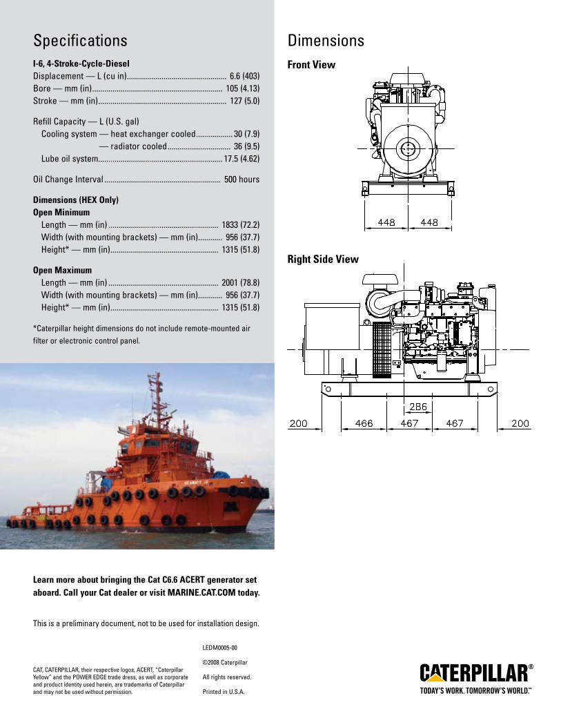
SpecificationsI-6, 4-Stroke-Cycle-DieselDisplacement—L(cuin) ................................................. 6.6(403)Bore — mm (in) ................................................................ 105(4.13)Stroke — mm (in) ............................................................... 127(5.0)
RefillCapacity—L(U.S.gal) Coolingsystem—heatexchangercooled .................. 30(7.9) — radiator cooled ............................... 36(9.5) Lubeoilsystem............................................................. 17.5(4.62)
OilChangeInterval ......................................................... 500hours
Dimensions (HeX only)open Minimum Length—mm(in) ...................................................... 1833(72.2) Width (with mounting brackets) — mm (in) ............ 956(37.7) Height* — mm (in) ..................................................... 1315(51.8)
open Maximum Length—mm(in) ...................................................... 2001(78.8) Width (with mounting brackets) — mm (in) ............ 956(37.7) Height* — mm (in) ..................................................... 1315(51.8)
*Caterpillar height dimensions do not include remote-mounted air filter or electronic control panel.
DimensionsFront View
right Side View
LEDM0005-00
©2008Caterpillar
All rights reserved.
PrintedinU.S.A.
CAT,CATERPILLAR,theirrespectivelogos, ACERT, “Caterpillar Yellow” and the POwEREDGE trade dress, as well as corporate and product identity used herein, are trademarks of Caterpillar and may not be used without permission.
Learn more about bringing the Cat C6.6 aCert generator set aboard. Call your Cat dealer or visit MarIne.Cat.CoM today.
This is a preliminary document, not to be used for installation design.


63
Appendix G – Machinery Specifications
Contents: Tugger Winch ........................................................................................................................G-1 Towing Winch .......................................................................................................................G-2 Fire Pumps .............................................................................................................................G-3 Crane ......................................................................................................................................G-4 Oil Skimmers .........................................................................................................................G-5 Towable Oil Bladders ............................................................................................................G-6 Typical Towed Barge .............................................................................................................G-7

DEPC- 52Electric Hawser Winch
Max. Drum Capacity: Over 770 feet of 9.5"/10.0" circumference synthetic line (9 layers).Rated Line-Pull: 47,300 lbs (near stall); 31,500 lbs rated line-pull at 67 feet per minute (barrel layer).Electric Motor & Drive: 75HP marine-duty electric motor with AC-variable frequency drive.Winch Braking: Total brake capacity of over 518,000 lbs at the second layer.
Air-set/release drum brake with joystick control, freewheel mode, and override lever.Winch Control: Wheelhouse controls with on-deck emergency stop and freewheel pushbuttons.Power Requirements: 460VAC 3 Phase, 60Hz. Other source voltage options available.Approximate Weight: 23,000 lbs.Winch Dimensions: 88.8" H x 83.7" W x 110.5" D.
The DEPC-52 is a single-drum electric hawser winch featuring automatic tension-selectablerender-recover mode, high braking capacities, and fast line speeds for escort and ship-assistvessels. All electrical components comply with ABS, USCG, and IEEE-45 standards.
WINCH SYSTEM SPECIFICATIONS
Markey Machinery Company, Inc.4634 East Marginal Way South, Suite C-140, Seattle, WA 98134
Phone: (206) 622-4697 Toll Free (800) 637-3430 Fax: (206) 623-9839Email: [email protected] by:
Griffin & Associates - 355 Grow Avenue NW, Bainbridge Island, WA 98110 (USA) Phone: 206-780-0509 Email: [email protected] Menge & Company, Inc - 5825 Plauche Street, New Orleans, LA 70123 (USA) Phone: 504-733-4871 Email: [email protected]

Markey's rugged hawser winches are built to thehighest quality workboat standards using materials
and processes providing maximum life and minimummaintenance in marine and outdoor applications.
Markey DEPC- 52 Winch
Innovation you can depend onInnovation you can depend onInnovation you can depend onInnovation you can depend onInnovation you can depend on
Explosion-proof electric motor and intrinsically-safe controlsDigital/Analog Line Tension Display SystemMultiple-station winch controlsHydraulic power systems and winch-drives availableModels available with or without fairleader, and with or without warping headProportional brake control availableA variety of source power configurations can be accommodatedElectrical hooks in system box for ship's UPSPerformance ratings can be tailored to suit specific applications
Hawser Winch System Options

TDSD-44Diesel Towing Winch
Max. Drum Capacity: Port and Starboard Drums, 3,340 feet of 2.75" wire (each). Rated Line-Pull: Maximum 460,000 lbs rated pull (stall) at barrel layer, in first gear. Diesel Power Unit: Performance based on GM8V-92 Diesel and CRT-5633 Transmission. Winch Brakes: Air-cylinder set and release (maximum 790,000 lbs), with handwheel for lock-down. Winch Controls: Pneumatic / Electric. Winch Dimensions: 108.5" H x 259.5" W x 227.0" D. Approximate Weight: 137,000 lbs.
The TDSD-44 is a reliable diesel-driven double-drum towing winch with high line-pull andbraking capacity, designed specifically for offshore towing or anchor-handling applications.Ruggedly built to provide decades of high performance with low maintenance requirements,the TDSD-44 is a proven industry workhorse suitable for even the most demanding jobs.
WINCH SYSTEM SPECIFICATIONS
Markey Machinery Company, Inc.4634 East Marginal Way South, Suite C-140, Seattle, WA 98134
Phone: (206) 622-4697 Toll Free (800) 637-3430 Fax: (206) 623-9839Email: [email protected] by:
Griffin & Associates - 355 Grow Avenue NW, Bainbridge Island, WA 98110 (USA) Phone: 206-780-0509 Email: [email protected] Menge & Company, Inc - 5825 Plauche Street, New Orleans, LA 70123 (USA) Phone: 504-733-4871 Email: [email protected]

Markey's rugged towing winches are built to thehighest quality workboat standards using materials
and processes providing maximum life and minimummaintenance in marine and outdoor applications.
Markey TDSD-44 Towing Winch
Innovation you can depend onInnovation you can depend onInnovation you can depend onInnovation you can depend onInnovation you can depend on
Single & Double Drum configurations availableDual fairleads availableWinch can be designed for chain-drive from Diesel Power Unit located below-deck or in the fidleyWinch can be designed for shaft-drive from Diesel Power Unit located in the fidleyDrum sizes can be changed to accomodate various rope capacity requirementsAuxiliary drum available to replace warping headDiesel, hydraulic & electric drives availablePerformance ratings can be tailored to suit specific applications2nd and 3rd-station winch controls availableMarine-duty epoxy paint system
Towing Winch System Options

FiFi Class Compliance FiFi 2 FiFi 2 FiFi 1 FiFi 1/2(No Int'l Class)
FiFi 1/2(No Int'l Class)
FiFi 0(No Int'l Class)
FiFi 0(No Int'l Class)
Water Volume Delivery 7,200 m3/h 7,200 m3/h 2,400 m3/h
Monitor Quantity Three to Four Three to Four Two Minimum
Water Throw150 Meters(500 Feet)
150 Meters(500 Feet)
120 Meters(400 Feet)
Water Height70 Meters(230 Feet)
70 Meters(230 Feet)
45 Meters(148 Feet)
Monitor Controls from Wheelhouse Remote, Electronic Remote, Electronic Remote, Electronic
MTT FIRE PUMP MODELSMTT FP - 16000(16,000 GPM)
FiFi 2
MTT FP - 8000(8,000 GPM)
FiFi 2
MTT FP - 10600(10,600 GPM)
FiFi 1
MTT FP - 5285(5,285 GPM)
FiFi 1/2
MTT PFP - 5285(5,285 GPM)
FiFi 1/2PORTABLE
MTT FP - 4400(4,400 GPM)
FiFi 0PORTABLE
MTT ABFP - 1700(1,700 GPM)
FiFi 0AIRBOAT *
Two (2) UnitsEqual FiFi 2
Four (4) UnitsEqual FiFi 2
One (1) UnitEquals FiFi 1
One (1) UnitEquals 1/2 FiFi
One (1) UnitEquals 1/2 FiFi
One (1) UnitEquals FiFi 0
One (1) UnitEquals FiFi 0
FiFi Class Compliance FiFi 2 FiFi 2 FiFi 1 FiFi 1/2 FiFi 1/2 FiFi 0 FiFi 0Water Volume Total Delivery Required to Reach FiFi Class 7,200 m3/h 7,200 m3/h 2,400 m3/h 1,200 m3/h 1,200 m3/h 1,000 m3/h ~ 385 m3/h
Monitor Quantity Minimum Required to Reach FiFi Class
Four Four Two One One One or Two Two to Four
Water Throw150 Meters(500 Feet)
150 Meters(500 Feet)
120 Meters(400 Feet)
120 Meters(400 Feet)
120 Meters(400 Feet)
117 Meters(385 Feet)
85 Meters(255 Feet)
Water Height70 Meters(230 Feet)
70 Meters(230 Feet)
45 Meters(148 Feet)
45 Meters(148 Feet)
45 Meters(148 Feet)
45 Meters(148 Feet)
35 Meters(105 Feet)
Monitor Controls from Wheelhouse Remote, Electronic Remote, Electronic Remote, Electronic Remote, Electronic Remote, Electronic Remote, Electronic Remote, Electronic
MTT FP - 16000(16,000 GPM)
FiFi 2
MTT FP - 8000(8,000 GPM)
FiFi 2
MTT FP - 10600(10,600 GPM)
FiFi 1
MTT FP - 5285(5,285 GPM)
FiFi 1/2
MTT PFP - 5285(5,285 GPM)
FiFi 1/2PORTABLE
MTT FP - 4400(4,400 GPM)
FiFi 0PORTABLE
MTT ABFP - 1700(1,700 GPM)
FiFi 0AIRBOAT
Gas Turbine 2 ea. Lycoming T-53's 1 ea. Lycoming T-53 1 ea. Lycoming T-53 1 ea. Lycoming T-53 Walter 601 Walter 601 RR Allison C-20BHorsepower at ISO 1,400 HP ea. 1,400 HP 1,400 HP 1.400 HP 600 HP 600 HP 420 HP
Engine to Pump Coupling - Falk a a a a a a aFuels - Diesel, Kerosene & Jet a a a a a a aAir Cooled w/On-Board Oil Cooler a a a a a a aMechanical Fuel Pump a a a a a a a12/24V Electrical w/Charger a a a a a a aOil, Fuel and Air Filtration a a a a a a aFull Analog Gauge Package a a a a a a a
MTT Fire Pump Model Listings and Ratings
MTT Units Required to Meet FiFi Class Compliance
Standard International Classifications for FiFi Fire Pump Units
Standard MTT Classifications for Fire Pump Units (FiFI Compliance)
Engine Configuration

High Temp & Low Oil Pres. Alarm a a a a a a aOver-Speed Governor Control a a a a a a a
MTT FP - 16000(16,000 GPM)
FiFi 2
MTT FP - 8000(8,000 GPM)
FiFi 2
MTT FP - 10600(10,600 GPM)
FiFi 1
MTT FP - 5285(5,285 GPM)
FiFi 1/2
MTT PFP - 5285(5,285 GPM)
FiFi 1/2PORTABLE
MTT FP - 4400(4,400 GPM)
FiFi 0PORTABLE
MTT ABFP - 1700(1,700 GPM)
FiFi 0AIRBOAT
Split Case Centrifugal with Cast Iron Case
Aurora Pump(or Equivalent)
Aurora Pump(or Equivalent)
Aurora Pump(or Equivalent)
Aurora Pump(or Equivalent)
Aurora Pump(or Equivalent)
Aurora Pump(or Equivalent)
Flowserve(or Equivalent)
Pump Quantity Required Per Unit Two (2) One (1) One (1) One (1) One (1) One (1) One (1)
Pump Flow and Pressure 3,634 m3/h @150 - 180 PSI
1,800 m3/h @150 - 180 PSI
2,400 m3/h @150 - 180 PSI
1.200 m3/h @150 - 180 PSI
1.200 m3/h @150 - 180 PSI
1,000 m3/h @150 - 180 PSI
~ 385 m3/h @150 - 180 PSI
Suction & Discharge16" Suction,
10" Discharge16" Suction,
10" Discharge16" Suction,
10" Discharge16" Suction,
10" Discharge14" Suction,
10" Discharge10" Suction,8" Discharge
6" Suction,Two 2.5" or Four 1.5"
Discharge
Suction ManifoldOne (1) ea.,16 per Pump
Six (6) ea.,Six Inch Flex Lines
Six (6) ea.,Six Inch Flex Lines
Five (5) ea.,Six Inch Flex Lines
Five (5) ea.,Six Inch Flex Lines
Three (3) ea.,Six Inch Flex Lines
One (1) ea.,Six Inch Flex Line
Suction ConfigurationVertical, Above or Below
Deck Horizontal, Deck
MountedHorizontal, Deck
MountedHorizontal, Deck
MountedHorizontal, Deck
MountedHorizontal, Deck
MountedHorizontal, Deck
Mounted
Foot Valves - As Required a a a a aVacuum Pump with
Sea StrainersVacuum Pump with
Sea StrainersMaximum Vertical Lift - Suction Entry to Pump
4.5 Meters(15 Feet)
4.5 Meters(15 Feet)
4.5 Meters(15 Feet)
4.5 Meters(15 Feet)
4.5 Meters(15 Feet)
4.5 Meters(15 Feet)
N/A (Suction Lines 5' from Waterline)
Speed1,800 RPM,
Stainless Shaft1,800 RPM,
Stainless Shaft1,800 RPM,
Stainless Shaft1,800 RPM,
Stainless Shaft1,800 RPM,
Stainless Shaft1,800 RPM,
Stainless Shaft3,600 RPM,
Stainless Shaft
MTT FP - 16000(16,000 GPM)
FiFi 2
MTT FP - 8000(8,000 GPM)
FiFi 2
MTT FP - 10600(10,600 GPM)
FiFi 1
MTT FP - 5285(5,285 GPM)
FiFi 1/2
MTT PFP - 5285(5,285 GPM)
FiFi 1/2PORTABLE
MTT FP - 4400(4,400 GPM)
FiFi 0PORTABLE
MTT ABFP - 1700(1,700 GPM)
FiFi 0AIRBOAT
Above Deck or Below Deck Both Both Both Both Above AboveUnder & Above Deck
(Combo)Skid Construction Heavy Duty Steel Heavy Duty Steel Heavy Duty Steel Heavy Duty Steel Aluminum Aluminum Aluminum
Engine Noise Attenuation a a a a a a aBlast Proof Lighting and Circuitry a a a a a a aSealed Access Door a a a a a a aAnti-Slip Surfaces a a a a N/A N/A N/A
Recessed Roof Ladder and Safety Railings a a a a N/A N/A N/A
Air Inlet with Spray Deflectors a a a a a a a
Pump is Mounted to Engine Output Shaft w/Flex Coupling / Drive Adapter a a a a a a a
Lifting Hooks at the Four Upper Corners a a a a a a N/A
Milspec 12V Gel Batteries are Rack Mount w/Perko Switch a a a a a a a
Watertight Breaker w/Ext. Resets a a a a a a aInsulated Stainless Steel Exhaust w/Roof Discharge & 2" Insulated Ceramic Blanket
a a a a a a N/A
Manual Roof Cover a a a a a a Not Applicable
Skid Configuration
Pump Configuration

Requires 480V, 3 Phase Power a a a a a a DC Power
Yellow Interior and Exterior Finish a a a a a a Custom Finish
MTT FP - 16000(16,000 GPM)
FiFi 2
MTT FP - 8000(8,000 GPM)
FiFi 2
MTT FP - 10600(10,600 GPM)
FiFi 1
MTT FP - 5285(5,285 GPM)
FiFi 1/2
MTT PFP - 5285(5,285 GPM)
FiFi 1/2PORTABLE
MTT FP - 4400(4,400 GPM)
FiFi 0PORTABLE
MTT ABFP - 1700(1,700 GPM)
FiFi 0AIRBOAT
Fuel Tank (per Specific Application) Per Specific Application Per Specific ApplicationPer Specific Application
Per Specific Application
Per Specific Application
Per Specific Application
Per Specific Application
Mechanical Fuel Pump for Turbine a a a a a a aElectric Fuel Priming Pump a a a a a a a1" Fuel Supply Line a a a a a a a
Fuel / Water Separation and Filtration a a a a a a a
Access Pipes for Supply Lines Located in Side of Container a a a a a a a
MTT FP - 16000(16,000 GPM)
FiFi 2
MTT FP - 8000(8,000 GPM)
FiFi 2
MTT FP - 10600(10,600 GPM)
FiFi 1
MTT FP - 5285(5,285 GPM)
FiFi 1/2
MTT PFP - 5285(5,285 GPM)
FiFi 1/2PORTABLE
MTT FP - 4400(4,400 GPM)
FiFi 0PORTABLE
MTT ABFP - 1700(1,700 GPM)
FiFi 0AIRBOAT
Water Delivery 3,634 m3/h at 150 Meters (500 Ft)
1,800 m3/h at 150 Meters (500 Ft)
2,400 m3/h at 120 Meters (400 Ft)
1,200 m3/h at 120 Meters (400 Ft)
1,200 m3/h at 120 Meters (400 Ft)
1,000 m3/h at 117 Meters (385 Feet)
~ 385 m3/h at 85 Meters (255 Feet)
Control Cable for Engine / Monitor for Remote Boxes
100 Feet of Cable 100 Feet of Cable 100 Feet of Cable 100 Feet of Cable 100 Feet of Cable 100 Feet of Cable 25 Feet of Cable
Monitor QTY Required Per Unit Two (2) One (1) Two (2) One (1) One (1) One (1)Two (2) to
Four (4) Nozzles
Monitor TypeStang 8" Electric Super
Low ProStang 8" Electric Super
Low ProStang 8" Electric Super Low Pro
Stang 6" Electric Super Low Pro
Stang 6" Electric Super Low Pro
Stang 6" Electric Super Low Pro
Stang Low Pro
Foam Capabilities a a a a a a a
MTT FP - 16000(16,000 GPM)
FiFi 2
MTT FP - 8000(8,000 GPM)
FiFi 2
MTT FP - 10600(10,600 GPM)
FiFi 1
MTT FP - 5285(5,285 GPM)
FiFi 1/2
MTT PFP - 5285(5,285 GPM)
FiFi 1/2PORTABLE
MTT FP - 4400(4,400 GPM)
FiFi 0PORTABLE
MTT ABFP - 1700(1,700 GPM)
FiFi 0AIRBOAT
MTT Test Run Prior to Shipping a a a a a a a
MTT Provides a 2" Valve Inlet to Allow Sea Water to Prime Pump a a a a Per Installation N/A N/A
MTT Provides ABS Statement of Fact a a a a a a aMTT Provides Installation Services on a Time and Materials Basis a a a a a a
MTT Installs at Factory
Customer Supplies Mounting of Unit to Vessel a a a a a a
MTT Installs at Factory
Customer Supplies 480V, 3 Phase Power to Unit a a a a a a
MTT Provides DC Power
FOB MTT Facility - Franklin, LA a a a a a a a
Installation and Shipping
Monitors
Fuel System

Approximate DimensionsMTT FP - 16000(16,000 GPM)
FiFi 2
MTT FP - 8000(8,000 GPM)
FiFi 2
MTT FP - 10600(10,600 GPM)
FiFi 1
MTT FP - 5285(5,285 GPM)
FiFi 1/2
MTT PFP - 5285(5,285 GPM)
FiFi 1/2PORTABLE
MTT FP - 4400(4,400 GPM)
FiFi 0PORTABLE
MTT ABFP - 1700(1,700 GPM)
FiFi 0AIRBOAT
Length2.54 Meters
(8 Feet, 4 Inches)4.12 Meters
(13 Feet, 6 Inches)4.12 Meters(13.6 Feet)
4.12 Meters(13 Feet, 6 Inches)
3.38 Meters(11 Feet, 1 Inches)
2.9 Meters(9 Feet, 6 Inches)
5.4 Meters(18 Feet)
Width2.90 Meters
(9 Feet, 6 Inches)1.83 Meters
(6 Feet)1.83 Meters
(6 Feet)1.83 Meters
(6 Feet)1.17 Meters
(3 Feet, 10 Inches)1.22 Meters
(4 Feet)2.44 Meters
(8 Feet)
Height2.2 Meters
(7 Feet, 3 Inches)3.66 Meters
(12 Feet)3 Meters(10 Feet)
3.0 Meters(10 Feet)
2.16 Meters(7 Feet, 1 Inch)
2.13 Meters(7 Feet)
3.05 Meters(10 Feet)
Weight Dry6,803 Kilos(15,000 lbs)
5,743 Kilos(12,660 lbs)
6,804 Kilos(15,000 lbs.)
5,216 Kilos(11,500 lbs.)
1,878 Kilos(4,140 lbs.)
2,322 Kilos(5,120 lbs.)
6,82 Kilos(1,500 lbs.)
Payment and AvailabilityMTT FP - 16000(16,000 GPM)
FiFi 2
MTT FP - 8000(8,000 GPM)
FiFi 2
MTT FP - 10600(10,600 GPM)
FiFi 1
MTT FP - 5285(5,285 GPM)
FiFi 1/2
MTT PFP - 5285(5,285 GPM)
FiFi 1/2PORTABLE
MTT FP - 4400(4,400 GPM)
FiFi 0PORTABLE
MTT ABFP - 1700(1,700 GPM)
FiFi 0AIRBOAT
Price Per Unit $ USD $ USD $ USD $ USD $ USD $ USD $ USD
Units Req'd to Reach FiFi ClassTwo (2) Units
for FiFi 2Four (4) Units
for FiFi 2One (1) Unit
for FiFi 1One (1) Unitfor 1/2 FiFi
One (1) Unitfor 1/2 FiFi
One (1) Unitfor 0 FiFi
One (1) Unitfor 0 FiFi
Total Price $ USD $ USD
Terms of Payment50% at Order, 50%
When Shipped50% at Order, 50%
When Shipped50% at Order, 50%
When Shipped50% at Order, 50%
When Shipped50% at Order, 50%
When Shipped50% at Order, 50%
When Shipped50% at Order, 50%
When ShippedProduction Lead Time ARO 12 - 16 Weeks 12 - 16 Weeks 12 - 16 Weeks 12 - 16 Weeks 12 - 16 Weeks 12 - 16 Weeks 12 - 16 Weeks
MTT Substitution of Components Allowed Prior to Order Acceptance a a a a a a a
Configuration Changes
Note: FiFi 2 Compliance Requirement if for DNV Regulations:(1) Monitor Qty: Two. (2) Water Throw: 180 Meters (590 ft). (3) Water Height: 110 Meters (360 ft).
* New Generation Airboat under construction. All specifications and performance ratings are estimated at the current time.
The Above are MTT's Standard Configurations and are subject to change at any time. Any customer additions or deletions to the Specification will require MTT engineering approval and a Price Adjustment.

Elevating Boats, LLC.
http://www.ebi-inc.com/[4/10/2010 4:52:29 PM]
Elevating Boats, LLC.201 Dean Court, Houma LA --- 900 St. Bernard Pkwy, Braithwaite, LA
Servicing the oil field for over 50 years.
Manufacturer of:Liftboats w Cranes w Gearboxes w Winches w Hydraulic Cylinders w Components
Home Liftboats Cranes CranesService Construction Components Jobs FAQ Contact
Us
Model TC60-43-73 EBI Telescopic Boom Cranes
STANDARD EQUIPMENT:
EBI CRANES ARE MANUFACTURED IN ACCORDANCEWITH API-2C SPECIFICATIONS.
EBI CRANES MEET ABS, USCG AND OSHAREQUIREMENTS.
PLANETARY SWING MECHANISM WITH ADJUSTABLEMOUNT, HIGH TORQUE MOTOR AND AUTOMATIC SPRINGAPPLIED BRAKES.
DOUBLE HYDRAULIC SWIVEL FOR CONTINUOUSROTATION.
OPTIONAL EQUIPMENT:
EBI CRANE CONTROL LOCATIONS:- PEDESTAL MOUNTED WALK-AROUND- REMOTELY LOCATED- VARIOUS PLATFORM CONFIGURATIONS- CAB MOUNTED JOY STICK TYPE
SOLAR/BATTERY POWERED BOOM BEACONS.
BOOM LIGHTING.
COMPLETE HYDRAULIC SAFETY SYSTEM DETECTINGTHE MOMENT INDUCED BY LOAD ON THE CRANE TO

Elevating Boats, LLC.
http://www.ebi-inc.com/[4/10/2010 4:52:29 PM]
INDUCTION HARDENED CHROME PLATED CYLINDERRODS.
18" I.D. MANWAY WITH BOLTED COVER.
THREE COLOR, SAFE LOAD INDICATOR GAUGE.
RACK AND PINION TELESCOPING SYSTEM. THERE ARENO INTERNAL BOOM CYLINDERS.
LOAD LINE WINCH: 2 SPEED MOTOR.
THREE COAT MARINE PAINT SYSTEM.
ANTI-FRICTION BEARINGS IN THE SHEAVES.
BRONZE BUSHINGS ON ALL PIVOTING POINTS.
LOAD TEST AT TWICE API DYNAMIC LOAD BEFORESHIPPING.
HELP PREVENT OVERLOAD CONDITION.
POWER UNITS CAN BE CRANE MOUNTED OR REMOTELYLOCATED.
POWER UNITS: ELECTRIC MOTOR, AIR MOTOR ORDIESEL ENGINE (DETROIT DIESEL, CUMMINS,CATERPILLAR, OR DEUTZ AIR-COOLED, ETC.)
DIESEL ENGINE STARTER SYSTEMS: ELECTRIC, AIR ORHYDRAULIC.
AIR/HYDRAULIC OIL HEAT EXCHANGER.
17-4PH STAINLESS STEEL, HEAT TREATED CHROMEPLATED CYLINDER RODS.
440C STAINLESS STEEL, HEAT TREATED PINS.
FAST LINE WINCH DESIGNED FOR PERSONNELHANDLING. WINCH CAPACITY IS 5000 LB. LINE PULL(1000 LB. FOR PERSONNEL).
ANTI-TWO BLOCK SYSTEM.
EMERGENCY LOAD LOWERING SYSTEM.
MODEL TC60-43-73 43 FT.RETRACTED
API LOAD CHART (U.S. CUSTOMARYUNITS)
REACH(FT.)
BOOMANGLE(DEG.)
DYNAMICLOAD(LBS.)
STATICLOAD(LBS.)
10 76 76300 78700
15 69 47950 72575
20 62 34300 52100
25 54 26400 40250
30 45 21200 32450
35 35 17850 27425
40 21 15100 23300
43 1 13800 21350
API PEDESTAL REACTIONS
MAXIMUM OTM = 2,743,707 FT. LBS.
CORRESPONDING AXIAL FORCE = 94,164 LBS.
MAXIMUM AXIAL FORCE = 202,437 LBS.
CORRESPONDING OTM = 1,870,871 FT. LBS.
BASIC CRANE WEIGHT = 37,500 LBS.

Elevating Boats, LLC.
http://www.ebi-inc.com/[4/10/2010 4:52:29 PM]
(REACTIONS @ 3 X DYNAMIC RATED LOAD)
(OTM = OVERTURNING MOMENT)
MODEL TC60-43-73 53 FT. EXTENDEDAPI LOAD CHART (U.S. CUSTOMARY
UNITS)REACH
(FT.)BOOMANGLE(DEG.)
DYNAMICLOAD(LBS.)
STATICLOAD(LBS.)
10 79 55500 78500
15 73 45500 69000
20 68 33500 51000
25 62 26300 40200
30 56 21000 32300
35 49 17500 27000
40 42 15000 23300
45 32 12800 19900
50 20 11000 17300
53 1 10300 16200
MODEL TC60-43-73 65 FT. EXTENDEDAPI LOAD CHART (U.S. CUSTOMARY
UNITS)REACH
(FT.)BOOMANGLE(DEG.)
DYNAMICLOAD(LBS.)
STATICLOAD(LBS.)
10 81 42000 63800
15 76 33000 50300
20 71 27000 41300
25 67 23500 36000
30 62 20500 31500
35 56 17300 26700
40 51 14800 22900
45 45 12800 19900
50 38 11000 17300
55 30 9800 15400
60 18 8800 13900
65 1 7800 12400
MODEL TC60-43-73 73 FT. EXTENDEDAPI LOAD CHART (U.S. CUSTOMARY
UNITS)REACH
(FT.)BOOMANGLE
DYNAMICLOAD
STATICLOAD

Elevating Boats, LLC.
http://www.ebi-inc.com/[4/10/2010 4:52:29 PM]
(DEG.) (LBS.) (LBS.)
10 82 39000 59300
15 78 28500 43500
20 74 23500 36000
25 70 19900 30600
30 66 17300 26700
35 61 14800 22900
40 57 13300 20700
45 52 11800 18400
50 47 10700 16700
55 41 9500 15000
60 35 8800 13900
65 27 8000 12800
70 17 7000 11300
73 1 6800 10900
IN ACCORDANCE WITH API-2C, VALUES SHOWN ARE ACTUAL HOOK LOADS (WEIGHT OF BLOCK AND HOOKEXCLUDED).
LOAD LINE BLOCK WEIGHT IS 1300 LBS.
LOAD LINE (4 PART LINE): 1" 6x25 EIPS IWRC; 100,000 LB. BREAKING STRENGTH; 20,000 LB. WORKING STRENGTH.
FAST LINE BLOCK IS 110 LBS.
FAST LINE (1 PART LINE): 9/16" 19x7 EIPS IWRC; 25,000 LB. BREAKING STRENGTH; 5000 LB. WORKING STRENGTH.
STATIC LOAD = 1.5 x DYNAMIC LOAD
PEDESTAL REACTIONS ARE BASED ON THREE TIMES THE DYNAMIC LOAD PLUS DEAD LOAD.
MODEL TC60-43-73 13.1 METERS RETRACTEDAPI LOAD CHART (INTERNATIONAL METRIC UNITS)
REACH(METERS)
BOOMANGLE(DEG.)
DYNAMICLOAD(KGS.)
STATICLOAD(KGS.)
3.0 76 34610 35698
4.6 69 21750 32920
6.1 62 15558 23633
7.6 54 11975 18257
9.1 45 9616 14719
10.7 35 8097 12440
12.2 21 6849 10569
13.1 1 6260 9684
BASIC CRANE WEIGHT = 17,010 KGS.

Elevating Boats, LLC.
http://www.ebi-inc.com/[4/10/2010 4:52:29 PM]
MODEL TC60-43-73 16.1 METERS EXTENDEDAPI LOAD CHART (INTERNATIONAL METRIC UNITS)
REACH(METERS)
BOOMANGLE(DEG.)
DYNAMICLOAD(KGS.)
STATICLOAD(KGS.)
3.0 79 25175 35608
4.6 73 20639 31298
6.1 68 15196 23134
7.6 62 11930 18235
9.1 56 9526 14651
10.7 49 7938 12247
12.2 42 6804 10569
13.7 32 5806 9027
15.2 20 4990 7847
16.2 1 4672 7348
MODEL TC60-43-73 19.8 METERS EXTENDEDAPI LOAD CHART (INTERNATIONAL METRIC UNITS)
REACH(METERS)
BOOMANGLE(DEG.)
DYNAMICLOAD(KGS.)
STATICLOAD(KGS.)
3.0 81 19051 28940
4.6 76 14969 22816
6.1 71 12247 18734
7.6 67 10660 16330
9.1 62 9300 14288
10.7 56 7847 12111
12.2 51 6713 10387
13.7 45 5806 9027
15.2 38 4990 7847
16.8 30 4445 6985
18.3 18 3992 6305
19.8 1 3538 5625
MODEL TC60-43-73 22.2 METERS EXTENDEDAPI LOAD CHART (INTERNATIONAL METRIC UNITS)
REACH(METERS)
BOOMANGLE(DEG.)
DYNAMICLOAD(KGS.)
STATICLOAD(KGS.)
3.0 82 17690 26898

Elevating Boats, LLC.
http://www.ebi-inc.com/[4/10/2010 4:52:29 PM]
4.6 78 12928 19732
6.1 74 10660 16330
7.6 70 9027 13880
9.1 66 7847 12111
10.7 61 6713 10387
12.2 57 6033 9390
13.7 52 5352 8346
15.2 47 4854 7575
16.8 41 4309 6804
18.3 35 3992 6305
19.8 27 3629 5806
21.3 17 3175 5126
22.9 1 3084 4944
IN ACCORDANCE WITH API-2C, VALUES SHOWN ARE ACTUAL HOOK LOADS (WEIGHT OF BLOCK AND HOOKEXCLUDED).
LOAD LINE BLOCK WEIGHT IS 590 KGS.
LOAD LINE (4 PART LINE): 1" 6x25 EIPS IWRC; 45,359 KGS. BREAKING STRENGTH; 9,072 KGS. WORKING STRENGTH.
FAST LINE BLOCK IS 50 KGS.
FAST LINE (1 PART LINE): 9/16" 19x7 EIPS IWRC; 11,340 KGS. BREAKING STRENGTH; 2,268 KGS. WORKING STRENGTH.
STATIC LOAD = 1.5 x DYNAMIC LOAD
PEDESTAL REACTIONS ARE BASED ON THREE TIMES THE DYNAMIC LOAD PLUS DEAD LOAD.
Model TC60-43-73 Telescopic Boom Crane
Available Configurations

Elevating Boats, LLC.
http://www.ebi-inc.com/[4/10/2010 4:52:29 PM]
TAIL SWING CHART at 0 deg. BOOM ANGLE *CONFIGURATION MAXIMUM TAIL SWING CONFIGURATION MAXIMUM TAIL SWING
1 4'-10" RADIUS 6
9'-3" RADIUS
2 5'-4" RADIUS 7
9'-3" RADIUS
3 7'-4" RADIUS 8 9'-8" RADIUS4 7'-4" RADIUS 9 9'-8" RADIUS5 7'-4" RADIUS 10 9'-8" RADIUS
*TAIL SWING VALUES MAY BE EXCEEDED DEPENDING UPON WINCH MOUNT OPTIONS.

The design of the DESMI TA-RANTULA skimmer has ben-efited from a continuing devel-opment program over nearly 20 years. The resulting system is the most versatile, powerful and seaworthy unit in its class.
All components are manufac-tured in marine grade alumin-ium, stainless steel or polypro-pylene.
Wireless remote control and thruster system to allow re-mote positioning of the skim-mer head and operation of the hose reel are available for the DESMI TARANTULA.
The DESMI TARANTULA incor-porates two powerful DESMI DOP-250 DUAL screw pumps that deliver a maximum total capacity of 250m3/h and can develop discharge pressures up to 10 bar while maintaining nearly maximum flow.
The DESMI TARANTULA skim-mer also has a self-adjusting weir lip which is controlled by the pumping rate. This enables the skimmer to handle a wide range of oils.
DESMI TARANTULA- High capacity offshore skimmer
The DESMI TARANTULA skimmer is the latest gen-eration offshore skimmer system from RO-CLEAN DESMI, and is the largest skimmer, ideal for offshore situations.
DES
MI
TA
RA
NTU
LA
PROvEN OIL SPILL TECHNOLOgy
PROvEN OIL SPILL TECHNOLOgy

Advantages of the DESMI TARAN-TULA:
• Affordable high capacity
• Capable of recovering a wide range of oils
• Self-adjusting weir
• Two independently controlledDOP-250 DUAL pumps
• Cutting knives fitted to pumpsfor trash handling
• Thrusters for remote positioning of skimmer
• Hydraulic knuckle crane matched with power pack
• Readily available parts
• Low maintenance
• The skimmer can also be fitted with disc or brush modules
www.ro-cleandesmi.com
TECHNICAL DATA
Nameplate capacity: 250 m³ per hour / 1100 US gpmInlet weir: Self-adjusting, 1.36 m / 53 in diameterOperating draught: 0.85 m / 33 in Weight: 340 kg / 750 lbs 380 kg / 838 lbs with thrustersOnboard pumps: 2 x DOP-250 DUALMax discharge pressure: 10 bar / 145 psiMax solids size: 50 mm / 2 in Pump discharge: 6 inMaximum hydraulic demand: 320 litres per min / 84 US gpm 210 bar / 3,045 ps iPower pack: 119 kW / 159 hpHydraulic hose connections (pumps): 2 x 1 in, 1 x 3/8 in drain plus thruster hoses (optional)Dimensions: 2.35 x 2.35 x 1.25 m / 92 x 92 x 49 in
All information is subject to change, and pictures are for illustration purposes only, and not necessarily correct.
Issue no 1
DES
MI
TA
RA
NTU
LA
- Contact one of the offices below for further information
PROvEN OIL SPILL TECHNOLOgy
Head OfficeRO-CLEAN DESMI A/SHestehaven 61DK-5260 Odense SPhone: + 45 65 48 16 10Fax: + 45 65 48 16 15E-mail: [email protected]
U.S.A. Office,APPLIED FABRIC TECHNOLOgIES INCPO Box 575,227 Thorn Ave,Orchard Park, Ny 14127Tel: +1 716 662 0632Fax: +1 716 662 0306E-mail: [email protected]
U.K. OfficeRO-CLEAN DESMI LTD.Unit 24, Shamrock QuayWilliam StreetSouthampton, SO14 5QLTel. +44 23 80829751Fax. +44 23 80339190E-mail: [email protected]
Asia OfficeRO-CLEAN DESMI ASIA50/F Menara BCAJl. MH. Thamrin No. 1Jakarta 13010 IndonesiaTel: +62 21 2358 4468Fax: +62 21 2358 4401E-mail: [email protected]
Latin America OfficeRO-CLEAN DESMI LATINOAMERICA S.A. Calle Amagasí del Inca E14-68 y 2° TransversalEdificio RO-CLEAN DESMI - PB Quito-EcuadorTel.: +593 2 326 1939 Fax: +593 2 326 4844E-mail: [email protected]

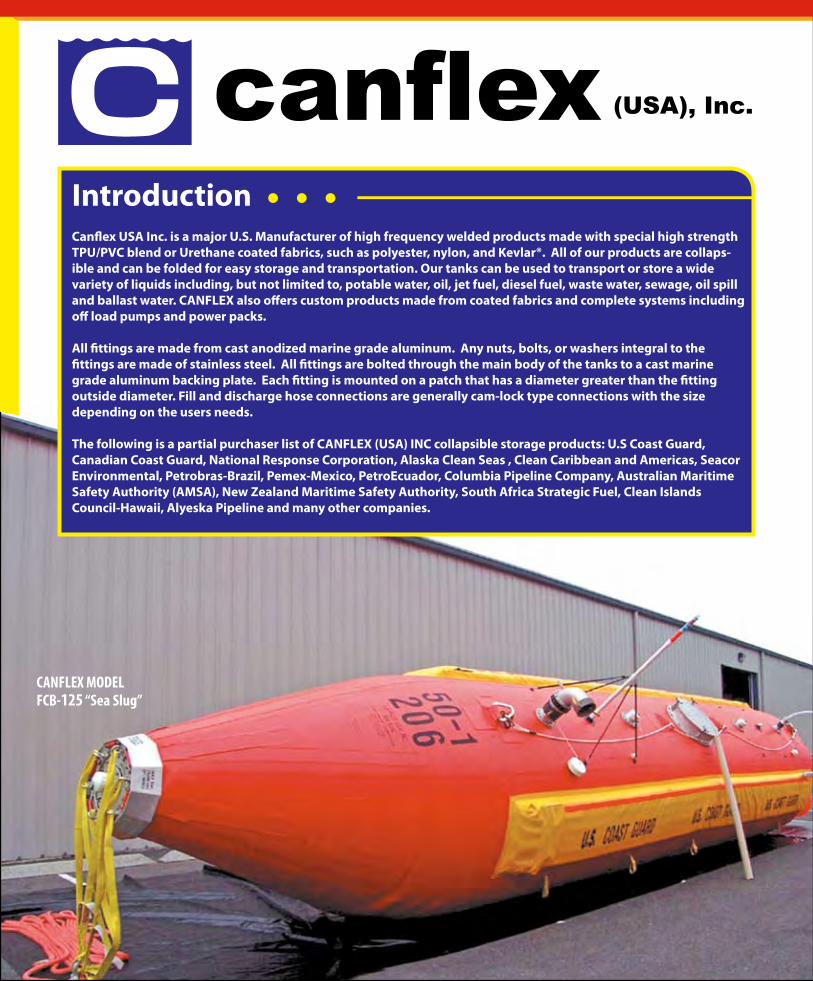
IntroductionCanflex USA Inc. is a major U.S. Manufacturer of high frequency welded products made with special high strength TPU/PVC blend or Urethane coated fabrics, such as polyester, nylon, and Kevlar®. All of our products are collaps-ible and can be folded for easy storage and transportation. Our tanks can be used to transport or store a wide variety of liquids including, but not limited to, potable water, oil, jet fuel, diesel fuel, waste water, sewage, oil spill and ballast water. CANFLEX also offers custom products made from coated fabrics and complete systems including off load pumps and power packs.
All fittings are made from cast anodized marine grade aluminum. Any nuts, bolts, or washers integral to the fittings are made of stainless steel. All fittings are bolted through the main body of the tanks to a cast marine grade aluminum backing plate. Each fitting is mounted on a patch that has a diameter greater than the fitting outside diameter. Fill and discharge hose connections are generally cam-lock type connections with the size depending on the users needs.
The following is a partial purchaser list of CANFLEX (USA) INC collapsible storage products: U.S Coast Guard, Canadian Coast Guard, National Response Corporation, Alaska Clean Seas , Clean Caribbean and Americas, Seacor Environmental, Petrobras-Brazil, Pemex-Mexico, PetroEcuador, Columbia Pipeline Company, Australian Maritime Safety Authority (AMSA), New Zealand Maritime Safety Authority, South Africa Strategic Fuel, Clean Islands Council-Hawaii, Alyeska Pipeline and many other companies.
CANFLEX MODELFCB-125 “Sea Slug”

Canflex “Sea Slug” bladders are very rugged units with a cylindrical main body and matching conical ends giving them great towing characteristics. The ends of the Sea Slug are constructed so the towing force is evenly distrib-uted through the fabric panels of the product, rather than distributing the tow forces throughout the hardware connecting the end fittings. This increases the product longevity. Canflex superior engineering& design along with the high strength coated fabrics used to manufacture the bladders allow them to be used safely for training and practical applications over an unlimited time period. Their coated fabric materials are many times stronger than materials used by other towable bladder manufacturers. This material strengh is critical for constructing a safe ocean towable bladder that can be filled, towed and off loaded repeatedly.
CANFLEX “SEA SLUG”Canflex “Sea Slug” Ocean Towable Bladders are normally used for Oil spill recovery and Temporary storage and are primarily used on water, they are however strong enough to be used for liquid storage on land. Special mate-rial coatings are available for these bladders to be used in many environments, such as storage and transport of Drinking water, Fuels or Waste products.
CANFLEX MODELFCB-125 “Sea Slug”
CANFLEX MODELFCB-60 “Sea Slug”
CANFLEX MODELFCB-25 “Sea Slug”

The Sea Slug is equipped with rectangular shaped flotation panels on each side. These floats are enclosed in water tight, covered pockets that run the full length of the bladder along the upper sides. Each float consists of several air chambers or closed cell foam, giving the float a low profile rectangular shape. Also, the use of multiple air chambers creates a high safety margin in case of a puncture or damage causing air leak in one of the chambers. The streamline and inherent flota-tion allow the Sea Slug to be used in ocean environments while filled with fluid, including high-density weathered oils.
The Sea Slug, inclined bow encloses an air inflatable bladder that ensures that the bow rides high in the water and maintains a streamlined shape for the optimum towing speed of the bladder when loaded.
CANFLEX MODELFCB-250 “Sea Slug”
Clip - Lok Box

CANFLEX (USA) INC offers a proven submersible pump off loading system for its “Sea Slug” ocean towable bladders. In addition Canflex offers a manufactured top center off-load hatch assembly that allows the submersible pump to be lowered into the center of the bladder . This top center hatch opening is available on the sizes of 25 m3 capacity and larger “Sea Slugs”. This is a fast and efficient method of off loading and is achieved by simply lowering the pump with the custom watertight cap with the pump attached into the Sea Slug. With the pump now locked inside the bladder all hydraulic power hoses and off-load fluid connections can quickly be connected to external fittings on its pump adaptation cap.
Canflex can offer positive displacement Archimedes screw pumps or Centrifugal screw submersible pumps with off load capacities from 20m3/h to 170m3/h.These high capacity pumps driven by their respective diesel engine powered hydraulic power packs will off-load a wide variety of fluids including high viscosity crude oils.Also available are non submersible portable diesel engine powered type pumps with off-load capacities from 11m3/h to 600m3/h. This type of pump can be connected to our stern off-load hose connection or at one of the top NPT flanged fittings.
The bladder high strength coated fabric material allows the bladder to be either folded or rolled into compact shape to fit into its custom aluminum storage / shipping container.
The CANFLEX (USA) INC durable Marine Grade aluminum shipping /storage containers are fork-lift able from all sides, collapsible from one side, and crane lift able.
The container has a lift off top cover and it is equipped with two screened air vents for ventila-tion. It also has a bottom drain and a replaceable inner liner for storing oily debris during a spill response, or for using the container or additional liquid storage.
Two Aluminum Containers (1) showing replaceable in-ner liner fitted (2) FCB-125, 50cu.m - 50 tonne (12,500 gallon) “Sea Slug” folded into cargo net and packed inside. Container Size: 100”-width x 75” - depth x 56” height
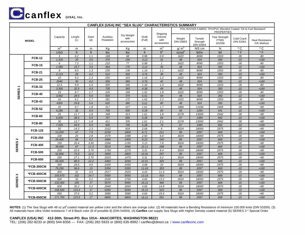
NOTES: (1) The Sea Slugs with 48 oz yd2 coated material are yellow color and the others are orange color. (2) All materials have a Bending Resistance of minimum 100.000 knits (DIN 53359). (3) All materials have Ultra Violet resistance 7 of 8 Black color (8 of possible 8) (DIN 54404). (4) Canflex can supply Sea Slugs with Higher Density coated material (5) SERIES 3 * Special Order CANFLEX (USA) INC 412-30th. Street-PO. Box 1014– ANACORTES, WASHINGTON 98221 TEL: (206) 282-8233 or (800) 544-8356 — FAX: (206) 282-5933 or (800) 635-8992 / [email protected] / www.canflexinc.com
SE
RIE
S 1
canflex (USA), Inc.
SE
RIE
S 2
SE
RIE
S 3
CANFLEX (USA) INC “SEA SLUG” CHARACTERISTICS SUMMARY
MODEL Capacity
Lenght
(L)
Diam (ø)
Auxiliary
Floatation
Dry Weight
with accessories
Draft (Full)
Shipping Volume
with accessories
POLYESTER FABRIC TPU/PVC Blended Coated “Oil & Fuel Resistant” PROPERTIES
Weight DIN 53853
Tensile
Strength DIN 53354
Tear Strength FTMS
191556 Cold Crack DIN 53361
Heat Resistance
IVK Method
m3 m m Kg Kg m m3 g/ m3 N/5 cm N º C º C USG ft ft lbs lbs ft ft3 oz/yd2 lbf/in lbf º F º F
FCB-12 5 6.2 1.1 168 68 0.98 0.9 1622 8090 1553 -30 -80 1,320 20 3.5 370 150 3.13 31 48 924 350 -22 +160
FCB-15 6 7.2 1.1 210 77 0.98 1 1622 8090 1553 -30 -80 1,585 23.7 3.5 464 170 3.13 35 48 924 350 -22 +160
FCB-21 8 8.5 1.3 230 136 1.16 1.1 1622 8090 1553 -30 -80 2,113 28 4.2 510 300 3.76 38 48 924 350 -22 +160
FCB-25 10 9.2 1.3 250 163 1.16 1.2 1622 8090 1553 -30 -80 2640 30 4.2 550 360 3.76 42 48 924 350 -22 +160
FCB-33 12.5 9.9 1.5 320 166 1.34 1.4 1622 8090 1553 -30 -80 3,300 32.5 4.9 705 365 4.38 49 48 924 350 -22 +160
FCB-40 15 8.7 1.7 226 168 1.52 1.8 1622 8090 1553 -30 -80 3,962 28.5 5.6 500 370 5.01 64 48 924 350 -22 +160
FCB-43 16 9.1 1.7 281 172 1.52 2.2 1622 8090 1553 -30 -80
4300 29.8 5.6 620 380 5.01 80 48 924 350 -22 +160
FCB-52 20 9.7 1.8 317 227 1.61 1.7 1884 11034 2406 -30 +80 5,285 32 5.9 700 500 5.28 60 56 1260 541 -22 +160
FCB-60 25 11.7 1.8 348 313 1.61 1.8 2278 13000 2942 -30 +80 6,600 38.5 5.9 767 690 5.28 64 67 1484 662 -22 +160
FCB-80 30 13.7 1.8 411 335 1.61 2.1 2278 13000 2942 -30 +80 7,925 44.9 5.9 906 740 5.28 74 67 1484 662 -22 +160
FCB-125 50 14.3 2.3 1012 818 2.06 6 3024 18000 2975 -30 +80 13,200 47 7.5 2230 1800 6.71 211 89 2057 669 -22 +160
FCB-250 100 20 2.8 1579 1088 2.50 6.8 3024 18000 2975 -30 +80 26,400 66 9.2 3480 2400 8.23 240 89 2057 669 -22 +160
FCB-400 150 20.4 3.50 1594 1150 3.13 7.6 3024 18000 2975 -30 +80 39,650 67 11.3 3515 2540 10.11 268 89 2057 669 -22 +160
FCB-500 200 22.6 3.70 1769 1270 3.31 8.4 3024 18000 2975 -30 +80 52,850 74.3 12.2 3900 2800 10.91 297 89 2057 669 -22 +160
FCB-650 250 27.1 3.70 2023 1470 3.31 9.2 3024 18000 2975 -30 +80 66,000 88.9 12.2 4460 3250 10.91 325 89 2057 669 -22 +160
*FCB-300CM 300 29.5 4.0 2429 2430 3.58 10 3024 18000 2975 -30 +80 79,250 96.6 13 5354 5350 11.63 353 89 2057 669 -22 +160
*FCB-400CM 400 31 4.5 2517 2520 4.03 11.6 3024 18000 2975 -30 +80 105,670 102 14.7 5550 5550 13.15 410 89 2057 669 -22 +160
*FCB-500CM 500 32 5.2 2530 2700 4.65 13.2 3024 18000 2975 -30 +80 132,000 105 17 5570 5950 15.21 466 89 2057 669 -22 +160
*FCB-600CM 600 35.2 5.2 2840 2840 4.65 14.8 3024 18000 2975 -30 +80 158,500 115.4 17 6260 6260 15.21 523 89 2057 669 -22 +160
*FCB-650CM
650 37.6 5.2 3080 3080 4.65 15.6 3024 18000 2975 -30 +80 171,700 123.5 17 6800 6800 15.21 551 89 2057 669 -22 +160

400 Series - 400’ x 99’6” x 20’
SpecificationsSummer Load LineKeel Draft 14' 2.75"
Summer Load LineDisplacement 15,416 ST
Summer Load LineDeadweight 12,035 ST
Lightship Draft 4' 0.5"
Lightship Displacement 3,380 ST
Lightship LCG 203.4 ft Forward of Transom
Lightship VCG 10.5 ft above Baseline
Draft Mark LocationsFwd Marks 320 ft Forward of TransomAft Marks 50 ft Forward of Transom
Longitudinal Strength DataMaximum Allowable Still Water Bending Moments
In Port 122,850 LT-ftAt Sea 57,950 LT-ft
Maximum Allowable Still Water Shear ForceIn Port 4,083 LTAt Sea 1,897 LT
www.crowley.com
© Crowley Maritime Corporation, 2004 CROWLEY is a registered trademark of Crowley Maritime Corporation
Liner Shipping • Worldwide Logistics • Project Management • Ship Assist & Escort • Alaska Fuel Sales & Distribution • Energy Support • Ocean Towing & Transportation • Salvage & Emergency Response • Petroleum & Chemical Transportation
CROWLEY®
People Who Know™

Summary of Allowable Loads
Transverse Frames Transverse Bulkheads Longitudinal BulkheadsUniform Linear Load - 16,247 lb/ft Uniform Linear Load - 33148 lbf/ft2 Uniform Linear Load - 31131 lbf/ft2Point Load - 162, - lbs Point Load - 331481lbf Point Load - 374192 lbf
(only over web frames) (only over web frames)
Nominal Overall Deck Load Rating Intersection of StructuresCounting Long'l Stiffeners - 1072 lbf/ft2 Transverse and Longitudinal Bulkheads - 449 KipsCounting only Frames, - 1625 lbf/ft2 Transverse Bulkhead and Side Shell - 620 KipsRail Girders and Bhds Transverse Frame and Side Shell - 519 Kips
RC O LW E YBARGE 400
A A A A A A A A A A A AB B B B B BC C C
A - Longitudinal Stiffeners B - Rail Girders C - Frame Stanchions
1102 S.W. Massachusetts Street • Seattle, Washington 98134 • (206) 332-8000
16701 Greenspoint Park Dr., Suite 195 • Houston, Texas 77060 • (281) 774-5400

64
Appendix H – Maneuvering
Contents: Maneuvering Prediction Output .............................................................................................H-1 Bow Thruster Specifications ..................................................................................................H-2

file:////storage.adsroot.itcs.umich.edu/home/windat.V2/Desktop/Maneuvering%20Output.txt[4/20/2010 11:09:20 PM]
University of Michigan Department of Naval Architecture and Marine Engineering Maneuvering Prediction Program (MPP-1.3) by M.G. Parsons References: Clarke,D., Gedling,P., and Hine,G., "The Application of Manoeuvring Criteria in Hull Design using Linear Theory," Trans. RINA, 1983 Lyster, C., and Knights, H. L., "Prediction Equations for Ships" Turning Circles," Trans. NECIES, 1978-1979 Run Identification: A Input Verification: Length of Waterline LWL (m) = 65.50 Maximum Beam on LWL (m) = 14.95 Mean Draft (m) = 5.63 Draft Forward (m) = 5.63 Draft Aft (m) = 5.63 Block Coefficient on LWL CB = 0.5210 Molded Volume (m^3) = 2872.98 Center of Gravity LCG (%LWL; + Fwd) = 51.4000 Center of Gravity LCG (m from FP) = -0.92 Midships to Rudder CE XR (%LWL; + Aft) = 49.0000 Rudder Center of Effort XR (m from FP) = 64.85 Initial Ship Speed (knots) = 16.00 Initial Ship Speed (m/s) = 8.2310 Water Type = Salt@15C Water Density (kg/m^3) = 1025.87 Kinematic Viscosity (m^2/s) = 0.118831E-05 Yaw Radius of Gyration K33/LWL = 0.2500 Water Depth to Ship Draft Ratio H/T = 1000.00 Steering Gear Time Constant (s) = 2.50 Total Rudder Area - Fraction of LWL*T = 0.0298

file:////storage.adsroot.itcs.umich.edu/home/windat.V2/Desktop/Maneuvering%20Output.txt[4/20/2010 11:09:20 PM]
Number of Propellers = 2 Number of Rudders = 2 Submerged Bow Area - Fraction of LWL*T = 0.0000 University of Michigan Department of Naval Architecture and Marine Engineering Maneuvering Prediction Program (MPP-1.3) by M.G. Parsons *** Linear Maneuvering Criteria Option *** Reference: Clarke,D., Gedling,P., and Hine,G., "The Application of Manoeuvring Criteria in Hull Design using Linear Theory," Trans. RINA, 1983 Run Identification: A Linear Maneuvering Derivatives Nondimensional Mass M prime = 0.020444 Nondimensional Mass Moment I sub zz = 0.001278 Sway Velocity Derivative Y sub v = -0.038365 Sway Acceleration Derivative Y sub v dot = -0.022187 Yaw Velocity Derivative N sub v = -0.015269 Yaw Acceleration Derivative N sub v dot = -0.003301 Sway Velocity Derivative Y sub r = 0.006011 Sway Acceleration Derivative Y sub r dot = -0.003010 Yaw Velocity Derivative N sub r = -0.005794 Yaw Acceleration Derivative N sub r dot = -0.000732 Sway Rudder Derivative Y sub delta = 0.007680 Yaw Rudder Derivative N sub delta = -0.003763 Time Constants and Gains for Nomoto"s Equation Dominant Ship Time Constant T1 prime = 1.1259 Ship Time Constant T2 prime = -0.2215

file:////storage.adsroot.itcs.umich.edu/home/windat.V2/Desktop/Maneuvering%20Output.txt[4/20/2010 11:09:20 PM]
Numerator Time Constant T3 prime = 1.0185 Numerator Time Constant T4 prime = 0.3694 1st Order Eqn. Time Constant T prime = -0.1141 Rudder Gain Factor K prime = -0.6459 Rudder Gain Factor K sub v prime = 0.4432 Steering Gear Time Constant TE prime = 0.3141 Evaluation of Turning Ability and Stability Inverse Time Constant 1/|T prime| = 8.7668 Inverse Gain Factor 1/|K prime| = 1.5481 Clarke"s Turning Index P = 11.2914 Linear Dynamic Stability Criterion C = 0.0004051 Vessel is hydrodynamically open loop course stable Closed Loop Phase Margin with Steering Engine = 84.2157 degrees University of Michigan Department of Naval Architecture and Marine Engineering Maneuvering Prediction Program (MPP-1.3) by M.G. Parsons *** Turning Prediction Option *** Reference: Lyster, C., and Knights, H. L., "Prediction Equations for Ships" Turning Circle", Trans. NECIES, 1978-1979 Run Identification: A Approach Speed = 16.00 knots Rudder Angle = 30.00 degrees Steady Turning Diameter = 312.83 meters Tactical Diameter = 321.83 meters Advance = 236.06 meters Transfer = 147.96 meters Steady Speed in Turn = 10.93 knots


65
Appendix I – Floodable Length
Contents: Floodable Length Results ......................................................................................................I-1


66
Appendix J – Intact Stability
Contents: USCG Wind Heel Requirement Spreadsheet ........................................................................J-1

U.S. Coast Guard Wind Heel GMt (R2) [46CFR170.170]
Draft T 5.63 m inputDepth D 7.50 mLength LOA 66.8 m outputBeam BOA 15 mDisplacement 2936 tFreeboard F 1.87 m
number length height #h abv DWL Az
Lateral Areas # [m] h [m] A [m2] z [m] moment
Main Deck 219.00 2.910 637.29Deckhouse 76.00 8.160 620.16Fly Bridge 72.00 15.100 1087.20Aft Structure 117.00 1.940 226.98
Summation 484.00 5.313 2571.63total area net z
h net z + T/2 = 8.128 m
P 0.05760 t/m2
min(14,atan(F/B)) 0.1240 radians 14 deg. = 0.2443 radians
GMt reqd 0.619 m
Note: these are the same deckhouse and superstructure profile view x h areas
used in the Watson and Gilfillan structural weight modeling.
Units in tonnes and meters

67
Appendix K – Damaged Stability
Contents: HECSALV Damage Stability Results ...................................................................................K-1


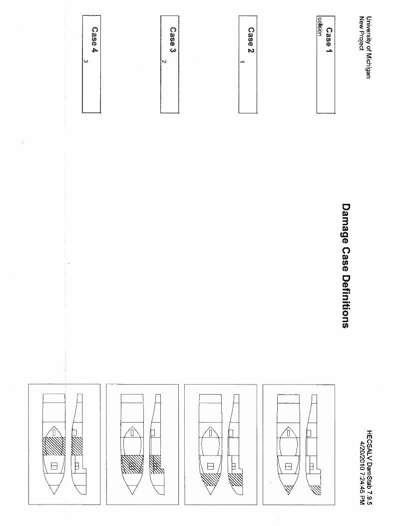


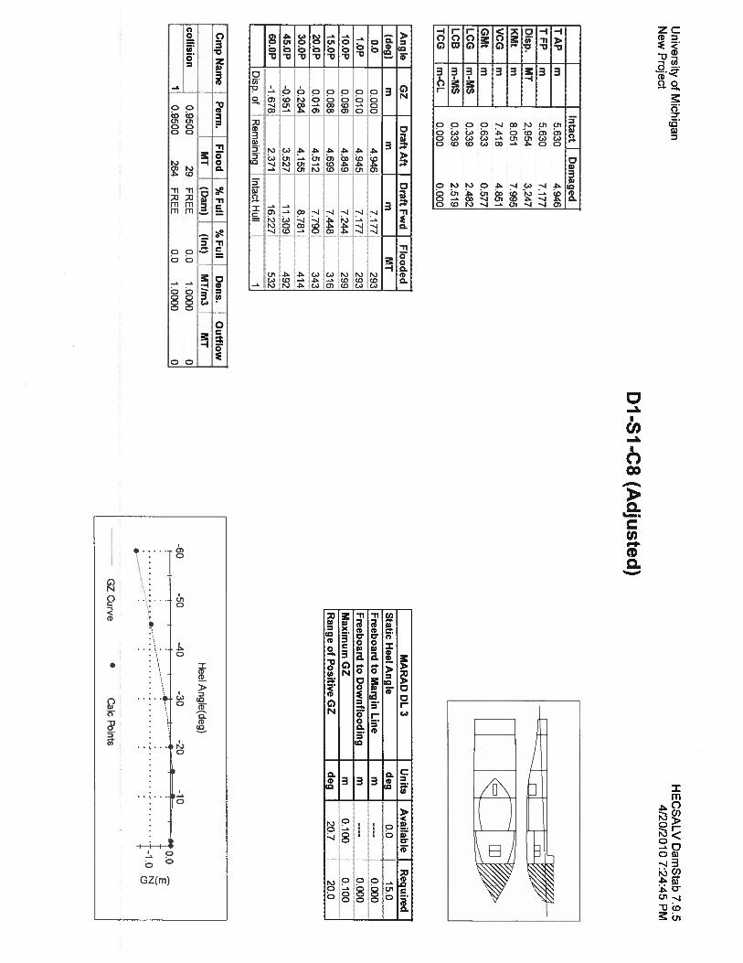


68
Appendix L – Seakeeping Results
Contents: Seakeeper Results ..................................................................................................................L-1

0, 0 kts; 0, 0 rad; Sea State 4 (ITTC (2 Param. Bretschneider): 8.8 s, 1.88 m)Item m0 units RMS units Significant amplitude units
1 Modal period 8.792 s -- --2 Characteristic wave height 1.88 m -- --3 Spectrum type ITTC (2 Param. Bretschneid -- --4 Wave heading 0 rad -- --5 Vessel Speed 0 kts -- --6 Vessel displacement 2867.584 m^3 -- --7 Vessel GMt 2.924 m -- --8 Vessel trim 0 rad -- --9 Transom method No transom terms -- --
10 Wave force method Arbitrary wave heading -- --11 Added res. method Salvesen -- --12 Pitch gyradius 16.711 m -- --13 Roll gyradius 4.58 m -- --14 Wave spectrum 0.221 m^2 0.47 m 0.94 m15 Encountered wave spectrum 0.221 m^2 0.47 m 0.94 m16 Added resistance 49.146 kN -- --17 Heave motion 0.073 m^2 0.27 m 0.539 m18 Roll motion 0 rad^2 0 rad 0 rad19 Pitch motion 0.0007 rad^2 0.02637 rad 0.05275 rad20 Heave velocity 0.039 m^2/s^2 0.197 m/s 0.394 m/s21 Roll velocity 0 (rad/s)^2 0 rad/s 0 rad/s22 Pitch velocity 0.00046 (rad/s)^2 0.02139 rad/s 0.04278 rad/s23 Heave acceleration 0.026 m^2/s^4 0.161 m/s^2 0.323 m/s^224 Roll acceleration 0 (rad/s/s)^2 0 rad/s/s 0 rad/s/s)25 Pitch acceleration 0.00033 (rad/s/s)^2 0.01826 rad/s/s 0.03652 rad/s/s)26 Wheelhouse: Abs. vert. motion 0.121 m^2 0.348 m 0.696 m27 Wheelhouse: Rel. vert. motion 0.17 m^2 0.412 m 0.824 m28 Wheelhouse: Abs. vert. velocity 0.08 m^2/s^2 0.284 m/s 0.567 m/s29 Wheelhouse: Rel. vert. velocity 0.209 m^2/s^2 0.457 m/s 0.914 m/s30 Wheelhouse: Abs. vert. accel 0.062 m^2/s^4 0.25 m/s^2 0.5 m/s^231 Wheelhouse: Rel. vert. accel 0.467 m^2/s^4 0.683 m/s^2 1.367 m/s^232 Wheelhouse: Long. (due to pitch) motion 0.082 m^2 0.287 m 0.574 m33 Wheelhouse: Long. (due to pitch) velocity 0.054 m^2/s^2 0.232 m/s 0.464 m/s34 Wheelhouse: Long. (due to pitch) accel 0.039 m^2/s^4 0.197 m/s^2 0.394 m/s^235 Wheelhouse: Lat. (due to roll) motion 0 m^2 0 m 0 m

36 Wheelhouse: Lat. (due to roll) velocity 0 m^2/s^2 0 m/s 0 m/s37 Wheelhouse: Lat. (due to roll) accel 0 m^2/s^4 0 m/s^2 0 m/s^238 Wheelhouse: MII slide; tip f/a; tip s/s 0 MII/h 0 MII/h 0 MII/h39 Workdeck: Abs. vert. motion 0.132 m^2 0.363 m 0.727 m40 Workdeck: Rel. vert. motion 0.072 m^2 0.269 m 0.537 m41 Workdeck: Abs. vert. velocity 0.073 m^2/s^2 0.27 m/s 0.539 m/s42 Workdeck: Rel. vert. velocity 0.121 m^2/s^2 0.348 m/s 0.696 m/s43 Workdeck: Abs. vert. accel 0.048 m^2/s^4 0.218 m/s^2 0.436 m/s^244 Workdeck: Rel. vert. accel 0.32 m^2/s^4 0.565 m/s^2 1.131 m/s^245 Workdeck: Long. (due to pitch) motion 0.01 m^2 0.1 m 0.201 m46 Workdeck: Long. (due to pitch) velocity 0.007 m^2/s^2 0.081 m/s 0.162 m/s47 Workdeck: Long. (due to pitch) accel 0.005 m^2/s^4 0.069 m/s^2 0.138 m/s^248 Workdeck: Lat. (due to roll) motion 0 m^2 0 m 0 m49 Workdeck: Lat. (due to roll) velocity 0 m^2/s^2 0 m/s 0 m/s50 Workdeck: Lat. (due to roll) accel 0 m^2/s^4 0 m/s^2 0 m/s^251 Workdeck: MII slide; tip f/a; tip s/s 0 MII/h 0 MII/h 0 MII/h
0, 0 kts; 0, 0 rad; Sea State 5 (ITTC (2 Param. Bretschneider): 9.7 s, 3.25 m)Item m0 units RMS units Significant amplitude units
1 Modal period 9.691 s -- --2 Characteristic wave height 3.25 m -- --3 Spectrum type ITTC (2 Param. Bretschneid -- --4 Wave heading 0 rad -- --5 Vessel Speed 0 kts -- --6 Vessel displacement 2867.584 m^3 -- --7 Vessel GMt 2.924 m -- --8 Vessel trim 0 rad -- --9 Transom method No transom terms -- --
10 Wave force method Arbitrary wave heading -- --11 Added res. method Salvesen -- --12 Pitch gyradius 16.711 m -- --13 Roll gyradius 4.58 m -- --14 Wave spectrum 0.66 m^2 0.812 m 1.625 m15 Encountered wave spectrum 0.66 m^2 0.812 m 1.625 m16 Added resistance 141.403 kN -- --17 Heave motion 0.282 m^2 0.531 m 1.061 m18 Roll motion 0 rad^2 0 rad 0 rad19 Pitch motion 0.00203 rad^2 0.04501 rad 0.09003 rad

20 Heave velocity 0.129 m^2/s^2 0.359 m/s 0.719 m/s21 Roll velocity 0 (rad/s)^2 0 rad/s 0 rad/s22 Pitch velocity 0.00124 (rad/s)^2 0.0352 rad/s 0.07039 rad/s23 Heave acceleration 0.074 m^2/s^4 0.272 m/s^2 0.545 m/s^224 Roll acceleration 0 (rad/s/s)^2 0 rad/s/s 0 rad/s/s)25 Pitch acceleration 0.00085 (rad/s/s)^2 0.02919 rad/s/s 0.05839 rad/s/s)26 Wheelhouse: Abs. vert. motion 0.39 m^2 0.625 m 1.25 m27 Wheelhouse: Rel. vert. motion 0.407 m^2 0.638 m 1.275 m28 Wheelhouse: Abs. vert. velocity 0.226 m^2/s^2 0.475 m/s 0.95 m/s29 Wheelhouse: Rel. vert. velocity 0.468 m^2/s^2 0.684 m/s 1.368 m/s30 Wheelhouse: Abs. vert. accel 0.159 m^2/s^4 0.398 m/s^2 0.797 m/s^231 Wheelhouse: Rel. vert. accel 0.985 m^2/s^4 0.992 m/s^2 1.985 m/s^232 Wheelhouse: Long. (due to pitch) motion 0.241 m^2 0.491 m 0.983 m33 Wheelhouse: Long. (due to pitch) velocity 0.146 m^2/s^2 0.382 m/s 0.765 m/s34 Wheelhouse: Long. (due to pitch) accel 0.1 m^2/s^4 0.316 m/s^2 0.632 m/s^235 Wheelhouse: Lat. (due to roll) motion 0 m^2 0 m 0 m36 Wheelhouse: Lat. (due to roll) velocity 0 m^2/s^2 0 m/s 0 m/s37 Wheelhouse: Lat. (due to roll) accel 0 m^2/s^4 0 m/s^2 0 m/s^238 Wheelhouse: MII slide; tip f/a; tip s/s 0 MII/h 0 MII/h 0 MII/h39 Workdeck: Abs. vert. motion 0.473 m^2 0.687 m 1.375 m40 Workdeck: Rel. vert. motion 0.157 m^2 0.397 m 0.794 m41 Workdeck: Abs. vert. velocity 0.23 m^2/s^2 0.479 m/s 0.959 m/s42 Workdeck: Rel. vert. velocity 0.258 m^2/s^2 0.508 m/s 1.015 m/s43 Workdeck: Abs. vert. accel 0.134 m^2/s^4 0.365 m/s^2 0.731 m/s^244 Workdeck: Rel. vert. accel 0.664 m^2/s^4 0.815 m/s^2 1.629 m/s^245 Workdeck: Long. (due to pitch) motion 0.03 m^2 0.172 m 0.344 m46 Workdeck: Long. (due to pitch) velocity 0.018 m^2/s^2 0.134 m/s 0.267 m/s47 Workdeck: Long. (due to pitch) accel 0.012 m^2/s^4 0.11 m/s^2 0.221 m/s^248 Workdeck: Lat. (due to roll) motion 0 m^2 0 m 0 m49 Workdeck: Lat. (due to roll) velocity 0 m^2/s^2 0 m/s 0 m/s50 Workdeck: Lat. (due to roll) accel 0 m^2/s^4 0 m/s^2 0 m/s^251 Workdeck: MII slide; tip f/a; tip s/s 0 MII/h 0 MII/h 0 MII/h
0, 0 kts; 0, 0 rad; Sea State 6 (ITTC (2 Param. Bretschneider): 12.4 s, 5 m)Item m0 units RMS units Significant amplitude units
1 Modal period 12.388 s -- --2 Characteristic wave height 5 m -- --3 Spectrum type ITTC (2 Param. Bretschneid -- --

4 Wave heading 0 rad -- --5 Vessel Speed 0 kts -- --6 Vessel displacement 2867.584 m^3 -- --7 Vessel GMt 2.924 m -- --8 Vessel trim 0 rad -- --9 Transom method No transom terms -- --
10 Wave force method Arbitrary wave heading -- --11 Added res. method Salvesen -- --12 Pitch gyradius 16.711 m -- --13 Roll gyradius 4.58 m -- --14 Wave spectrum 1.563 m^2 1.25 m 2.5 m15 Encountered wave spectrum 1.563 m^2 1.25 m 2.5 m16 Added resistance 285.385 kN -- --17 Heave motion 1.025 m^2 1.012 m 2.025 m18 Roll motion 0 rad^2 0 rad 0 rad19 Pitch motion 0.00353 rad^2 0.05942 rad 0.11883 rad20 Heave velocity 0.33 m^2/s^2 0.574 m/s 1.149 m/s21 Roll velocity 0 (rad/s)^2 0 rad/s 0 rad/s22 Pitch velocity 0.00181 (rad/s)^2 0.04254 rad/s 0.08508 rad/s23 Heave acceleration 0.135 m^2/s^4 0.367 m/s^2 0.734 m/s^224 Roll acceleration 0 (rad/s/s)^2 0 rad/s/s 0 rad/s/s)25 Pitch acceleration 0.0011 (rad/s/s)^2 0.03315 rad/s/s 0.0663 rad/s/s)26 Wheelhouse: Abs. vert. motion 1.083 m^2 1.041 m 2.082 m27 Wheelhouse: Rel. vert. motion 0.488 m^2 0.699 m 1.397 m28 Wheelhouse: Abs. vert. velocity 0.42 m^2/s^2 0.648 m/s 1.296 m/s29 Wheelhouse: Rel. vert. velocity 0.489 m^2/s^2 0.699 m/s 1.399 m/s30 Wheelhouse: Abs. vert. accel 0.222 m^2/s^4 0.471 m/s^2 0.942 m/s^231 Wheelhouse: Rel. vert. accel 0.93 m^2/s^4 0.964 m/s^2 1.928 m/s^232 Wheelhouse: Long. (due to pitch) motion 0.428 m^2 0.654 m 1.309 m33 Wheelhouse: Long. (due to pitch) velocity 0.216 m^2/s^2 0.465 m/s 0.93 m/s34 Wheelhouse: Long. (due to pitch) accel 0.13 m^2/s^4 0.36 m/s^2 0.72 m/s^235 Wheelhouse: Lat. (due to roll) motion 0 m^2 0 m 0 m36 Wheelhouse: Lat. (due to roll) velocity 0 m^2/s^2 0 m/s 0 m/s37 Wheelhouse: Lat. (due to roll) accel 0 m^2/s^4 0 m/s^2 0 m/s^238 Wheelhouse: MII slide; tip f/a; tip s/s 0 MII/h 0 MII/h 0 MII/h39 Workdeck: Abs. vert. motion 1.431 m^2 1.196 m 2.392 m40 Workdeck: Rel. vert. motion 0.156 m^2 0.395 m 0.79 m

41 Workdeck: Abs. vert. velocity 0.505 m^2/s^2 0.711 m/s 1.421 m/s42 Workdeck: Rel. vert. velocity 0.245 m^2/s^2 0.495 m/s 0.99 m/s43 Workdeck: Abs. vert. accel 0.223 m^2/s^4 0.473 m/s^2 0.945 m/s^244 Workdeck: Rel. vert. accel 0.608 m^2/s^4 0.78 m/s^2 1.559 m/s^245 Workdeck: Long. (due to pitch) motion 0.052 m^2 0.229 m 0.458 m46 Workdeck: Long. (due to pitch) velocity 0.026 m^2/s^2 0.163 m/s 0.325 m/s47 Workdeck: Long. (due to pitch) accel 0.016 m^2/s^4 0.126 m/s^2 0.252 m/s^248 Workdeck: Lat. (due to roll) motion 0 m^2 0 m 0 m49 Workdeck: Lat. (due to roll) velocity 0 m^2/s^2 0 m/s 0 m/s50 Workdeck: Lat. (due to roll) accel 0 m^2/s^4 0 m/s^2 0 m/s^251 Workdeck: MII slide; tip f/a; tip s/s 0 MII/h 0 MII/h 0 MII/h
0, 0 kts; 30, 0.52 rad; Sea State 4 (ITTC (2 Param. Bretschneider): 8.8 s, 1.88 m)Item m0 units RMS units Significant amplitude units
1 Modal period 8.792 s -- --2 Characteristic wave height 1.88 m -- --3 Spectrum type ITTC (2 Param. Bretschneid -- --4 Wave heading 0.52 rad -- --5 Vessel Speed 0 kts -- --6 Vessel displacement 2867.584 m^3 -- --7 Vessel GMt 2.924 m -- --8 Vessel trim 0 rad -- --9 Transom method No transom terms -- --
10 Wave force method Arbitrary wave heading -- --11 Added res. method Salvesen -- --12 Pitch gyradius 16.711 m -- --13 Roll gyradius 4.58 m -- --14 Wave spectrum 0.221 m^2 0.47 m 0.94 m15 Encountered wave spectrum 0.221 m^2 0.47 m 0.94 m16 Added resistance 50.304 kN -- --17 Heave motion 0.094 m^2 0.307 m 0.614 m18 Roll motion 0.00166 rad^2 0.04069 rad 0.08138 rad19 Pitch motion 0.00067 rad^2 0.02584 rad 0.05168 rad20 Heave velocity 0.052 m^2/s^2 0.227 m/s 0.454 m/s21 Roll velocity 0.00196 (rad/s)^2 0.04425 rad/s 0.08849 rad/s22 Pitch velocity 0.00046 (rad/s)^2 0.02147 rad/s 0.04295 rad/s23 Heave acceleration 0.035 m^2/s^4 0.186 m/s^2 0.372 m/s^224 Roll acceleration 0.00349 (rad/s/s)^2 0.05905 rad/s/s 0.1181 rad/s/s)

25 Pitch acceleration 0.00035 (rad/s/s)^2 0.01884 rad/s/s 0.03767 rad/s/s)26 Wheelhouse: Abs. vert. motion 0.117 m^2 0.342 m 0.684 m27 Wheelhouse: Rel. vert. motion 0.137 m^2 0.371 m 0.741 m28 Wheelhouse: Abs. vert. velocity 0.08 m^2/s^2 0.283 m/s 0.566 m/s29 Wheelhouse: Rel. vert. velocity 0.181 m^2/s^2 0.425 m/s 0.85 m/s30 Wheelhouse: Abs. vert. accel 0.065 m^2/s^4 0.255 m/s^2 0.511 m/s^231 Wheelhouse: Rel. vert. accel 0.446 m^2/s^4 0.668 m/s^2 1.336 m/s^232 Wheelhouse: Long. (due to pitch) motion 0.079 m^2 0.281 m 0.563 m33 Wheelhouse: Long. (due to pitch) velocity 0.054 m^2/s^2 0.233 m/s 0.466 m/s34 Wheelhouse: Long. (due to pitch) accel 0.042 m^2/s^4 0.204 m/s^2 0.408 m/s^235 Wheelhouse: Lat. (due to roll) motion 0.2 m^2 0.447 m 0.894 m36 Wheelhouse: Lat. (due to roll) velocity 0.234 m^2/s^2 0.484 m/s 0.968 m/s37 Wheelhouse: Lat. (due to roll) accel 0.412 m^2/s^4 0.642 m/s^2 1.283 m/s^238 Wheelhouse: MII slide; tip f/a; tip s/s 0 MII/h 0.006 MII/h 0 MII/h39 Workdeck: Abs. vert. motion 0.215 m^2 0.463 m 0.927 m40 Workdeck: Rel. vert. motion 0.059 m^2 0.244 m 0.488 m41 Workdeck: Abs. vert. velocity 0.129 m^2/s^2 0.359 m/s 0.719 m/s42 Workdeck: Rel. vert. velocity 0.123 m^2/s^2 0.351 m/s 0.702 m/s43 Workdeck: Abs. vert. accel 0.098 m^2/s^4 0.312 m/s^2 0.625 m/s^244 Workdeck: Rel. vert. accel 0.393 m^2/s^4 0.627 m/s^2 1.254 m/s^245 Workdeck: Long. (due to pitch) motion 0.01 m^2 0.098 m 0.197 m46 Workdeck: Long. (due to pitch) velocity 0.007 m^2/s^2 0.082 m/s 0.163 m/s47 Workdeck: Long. (due to pitch) accel 0.005 m^2/s^4 0.071 m/s^2 0.143 m/s^248 Workdeck: Lat. (due to roll) motion 0.024 m^2 0.156 m 0.313 m49 Workdeck: Lat. (due to roll) velocity 0.029 m^2/s^2 0.169 m/s 0.339 m/s50 Workdeck: Lat. (due to roll) accel 0.05 m^2/s^4 0.224 m/s^2 0.449 m/s^251 Workdeck: MII slide; tip f/a; tip s/s 0 MII/h 0 MII/h 0 MII/h
0, 0 kts; 30, 0.52 rad; Sea State 5 (ITTC (2 Param. Bretschneider): 9.7 s, 3.25 m)Item m0 units RMS units Significant amplitude units
1 Modal period 9.691 s -- --2 Characteristic wave height 3.25 m -- --3 Spectrum type ITTC (2 Param. Bretschneid -- --4 Wave heading 0.52 rad -- --5 Vessel Speed 0 kts -- --6 Vessel displacement 2867.584 m^3 -- --7 Vessel GMt 2.924 m -- --8 Vessel trim 0 rad -- --
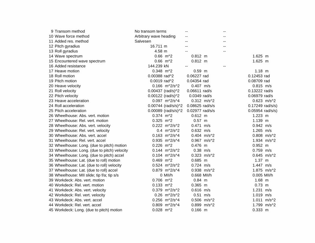
9 Transom method No transom terms -- --10 Wave force method Arbitrary wave heading -- --11 Added res. method Salvesen -- --12 Pitch gyradius 16.711 m -- --13 Roll gyradius 4.58 m -- --14 Wave spectrum 0.66 m^2 0.812 m 1.625 m15 Encountered wave spectrum 0.66 m^2 0.812 m 1.625 m16 Added resistance 144.239 kN -- --17 Heave motion 0.348 m^2 0.59 m 1.18 m18 Roll motion 0.00388 rad^2 0.06227 rad 0.12453 rad19 Pitch motion 0.0019 rad^2 0.04354 rad 0.08709 rad20 Heave velocity 0.166 m^2/s^2 0.407 m/s 0.815 m/s21 Roll velocity 0.00437 (rad/s)^2 0.06611 rad/s 0.13222 rad/s22 Pitch velocity 0.00122 (rad/s)^2 0.0349 rad/s 0.06979 rad/s23 Heave acceleration 0.097 m^2/s^4 0.312 m/s^2 0.623 m/s^224 Roll acceleration 0.00744 (rad/s/s)^2 0.08625 rad/s/s 0.17249 rad/s/s)25 Pitch acceleration 0.00089 (rad/s/s)^2 0.02977 rad/s/s 0.05954 rad/s/s)26 Wheelhouse: Abs. vert. motion 0.374 m^2 0.612 m 1.223 m27 Wheelhouse: Rel. vert. motion 0.325 m^2 0.57 m 1.139 m28 Wheelhouse: Abs. vert. velocity 0.222 m^2/s^2 0.471 m/s 0.942 m/s29 Wheelhouse: Rel. vert. velocity 0.4 m^2/s^2 0.632 m/s 1.265 m/s30 Wheelhouse: Abs. vert. accel 0.163 m^2/s^4 0.404 m/s^2 0.808 m/s^231 Wheelhouse: Rel. vert. accel 0.935 m^2/s^4 0.967 m/s^2 1.934 m/s^232 Wheelhouse: Long. (due to pitch) motion 0.226 m^2 0.476 m 0.952 m33 Wheelhouse: Long. (due to pitch) velocity 0.144 m^2/s^2 0.38 m/s 0.759 m/s34 Wheelhouse: Long. (due to pitch) accel 0.104 m^2/s^4 0.323 m/s^2 0.645 m/s^235 Wheelhouse: Lat. (due to roll) motion 0.469 m^2 0.685 m 1.37 m36 Wheelhouse: Lat. (due to roll) velocity 0.524 m^2/s^2 0.724 m/s 1.447 m/s37 Wheelhouse: Lat. (due to roll) accel 0.879 m^2/s^4 0.938 m/s^2 1.875 m/s^238 Wheelhouse: MII slide; tip f/a; tip s/s 0 MII/h 0.668 MII/h 0.005 MII/h39 Workdeck: Abs. vert. motion 0.706 m^2 0.84 m 1.68 m40 Workdeck: Rel. vert. motion 0.133 m^2 0.365 m 0.73 m41 Workdeck: Abs. vert. velocity 0.379 m^2/s^2 0.616 m/s 1.231 m/s42 Workdeck: Rel. vert. velocity 0.26 m^2/s^2 0.51 m/s 1.019 m/s43 Workdeck: Abs. vert. accel 0.256 m^2/s^4 0.506 m/s^2 1.011 m/s^244 Workdeck: Rel. vert. accel 0.809 m^2/s^4 0.899 m/s^2 1.799 m/s^245 Workdeck: Long. (due to pitch) motion 0.028 m^2 0.166 m 0.333 m

46 Workdeck: Long. (due to pitch) velocity 0.018 m^2/s^2 0.133 m/s 0.266 m/s47 Workdeck: Long. (due to pitch) accel 0.013 m^2/s^4 0.113 m/s^2 0.226 m/s^248 Workdeck: Lat. (due to roll) motion 0.057 m^2 0.24 m 0.479 m49 Workdeck: Lat. (due to roll) velocity 0.064 m^2/s^2 0.253 m/s 0.506 m/s50 Workdeck: Lat. (due to roll) accel 0.108 m^2/s^4 0.328 m/s^2 0.656 m/s^251 Workdeck: MII slide; tip f/a; tip s/s 0 MII/h 0.015 MII/h 0 MII/h
0, 0 kts; 30, 0.52 rad; Sea State 6 (ITTC (2 Param. Bretschneider): 12.4 s, 5 m)Item m0 units RMS units Significant amplitude units
1 Modal period 12.388 s -- --2 Characteristic wave height 5 m -- --3 Spectrum type ITTC (2 Param. Bretschneid -- --4 Wave heading 0.52 rad -- --5 Vessel Speed 0 kts -- --6 Vessel displacement 2867.584 m^3 -- --7 Vessel GMt 2.924 m -- --8 Vessel trim 0 rad -- --9 Transom method No transom terms -- --
10 Wave force method Arbitrary wave heading -- --11 Added res. method Salvesen -- --12 Pitch gyradius 16.711 m -- --13 Roll gyradius 4.58 m -- --14 Wave spectrum 1.563 m^2 1.25 m 2.5 m15 Encountered wave spectrum 1.563 m^2 1.25 m 2.5 m16 Added resistance 290.432 kN -- --17 Heave motion 1.156 m^2 1.075 m 2.15 m18 Roll motion 0.00441 rad^2 0.06644 rad 0.13288 rad19 Pitch motion 0.00315 rad^2 0.05615 rad 0.11231 rad20 Heave velocity 0.39 m^2/s^2 0.624 m/s 1.249 m/s21 Roll velocity 0.00451 (rad/s)^2 0.06717 rad/s 0.13434 rad/s22 Pitch velocity 0.0017 (rad/s)^2 0.04127 rad/s 0.08254 rad/s23 Heave acceleration 0.167 m^2/s^4 0.409 m/s^2 0.818 m/s^224 Roll acceleration 0.00712 (rad/s/s)^2 0.0844 rad/s/s 0.1688 rad/s/s)25 Pitch acceleration 0.0011 (rad/s/s)^2 0.03316 rad/s/s 0.06631 rad/s/s)26 Wheelhouse: Abs. vert. motion 1.046 m^2 1.023 m 2.046 m27 Wheelhouse: Rel. vert. motion 0.377 m^2 0.614 m 1.228 m28 Wheelhouse: Abs. vert. velocity 0.408 m^2/s^2 0.639 m/s 1.278 m/s29 Wheelhouse: Rel. vert. velocity 0.41 m^2/s^2 0.64 m/s 1.28 m/s

30 Wheelhouse: Abs. vert. accel 0.223 m^2/s^4 0.472 m/s^2 0.944 m/s^231 Wheelhouse: Rel. vert. accel 0.873 m^2/s^4 0.935 m/s^2 1.869 m/s^232 Wheelhouse: Long. (due to pitch) motion 0.383 m^2 0.619 m 1.238 m33 Wheelhouse: Long. (due to pitch) velocity 0.204 m^2/s^2 0.452 m/s 0.903 m/s34 Wheelhouse: Long. (due to pitch) accel 0.13 m^2/s^4 0.361 m/s^2 0.721 m/s^235 Wheelhouse: Lat. (due to roll) motion 0.539 m^2 0.734 m 1.468 m36 Wheelhouse: Lat. (due to roll) velocity 0.543 m^2/s^2 0.737 m/s 1.474 m/s37 Wheelhouse: Lat. (due to roll) accel 0.844 m^2/s^4 0.919 m/s^2 1.837 m/s^238 Wheelhouse: MII slide; tip f/a; tip s/s 0 MII/h 0.523 MII/h 0.003 MII/h39 Workdeck: Abs. vert. motion 1.816 m^2 1.348 m 2.695 m40 Workdeck: Rel. vert. motion 0.155 m^2 0.394 m 0.787 m41 Workdeck: Abs. vert. velocity 0.713 m^2/s^2 0.845 m/s 1.689 m/s42 Workdeck: Rel. vert. velocity 0.249 m^2/s^2 0.499 m/s 0.998 m/s43 Workdeck: Abs. vert. accel 0.37 m^2/s^4 0.608 m/s^2 1.216 m/s^244 Workdeck: Rel. vert. accel 0.735 m^2/s^4 0.857 m/s^2 1.715 m/s^245 Workdeck: Long. (due to pitch) motion 0.047 m^2 0.217 m 0.433 m46 Workdeck: Long. (due to pitch) velocity 0.025 m^2/s^2 0.158 m/s 0.316 m/s47 Workdeck: Long. (due to pitch) accel 0.016 m^2/s^4 0.126 m/s^2 0.252 m/s^248 Workdeck: Lat. (due to roll) motion 0.066 m^2 0.257 m 0.513 m49 Workdeck: Lat. (due to roll) velocity 0.066 m^2/s^2 0.258 m/s 0.515 m/s50 Workdeck: Lat. (due to roll) accel 0.103 m^2/s^4 0.321 m/s^2 0.643 m/s^251 Workdeck: MII slide; tip f/a; tip s/s 0 MII/h 0.059 MII/h 0.001 MII/h
0, 0 kts; 90, 1.57 rad; Sea State 4 (ITTC (2 Param. Bretschneider): 8.8 s, 1.88 m)Item m0 units RMS units Significant amplitude units
1 Modal period 8.792 s -- --2 Characteristic wave height 1.88 m -- --3 Spectrum type ITTC (2 Param. Bretschneid -- --4 Wave heading 1.57 rad -- --5 Vessel Speed 0 kts -- --6 Vessel displacement 2867.584 m^3 -- --7 Vessel GMt 2.924 m -- --8 Vessel trim 0 rad -- --9 Transom method No transom terms -- --
10 Wave force method Arbitrary wave heading -- --11 Added res. method Salvesen -- --12 Pitch gyradius 16.711 m -- --13 Roll gyradius 4.58 m -- --

14 Wave spectrum 0.221 m^2 0.47 m 0.94 m15 Encountered wave spectrum 0.221 m^2 0.47 m 0.94 m16 Added resistance 45.402 kN -- --17 Heave motion 0.279 m^2 0.529 m 1.057 m18 Roll motion 0.00671 rad^2 0.08189 rad 0.16378 rad19 Pitch motion 0.00016 rad^2 0.0125 rad 0.025 rad20 Heave velocity 0.218 m^2/s^2 0.467 m/s 0.934 m/s21 Roll velocity 0.00793 (rad/s)^2 0.08905 rad/s 0.1781 rad/s22 Pitch velocity 0.00012 (rad/s)^2 0.01094 rad/s 0.02187 rad/s23 Heave acceleration 0.21 m^2/s^4 0.458 m/s^2 0.917 m/s^224 Roll acceleration 0.01412 (rad/s/s)^2 0.11884 rad/s/s 0.23768 rad/s/s)25 Pitch acceleration 0.00011 (rad/s/s)^2 0.01028 rad/s/s 0.02055 rad/s/s)26 Wheelhouse: Abs. vert. motion 0.155 m^2 0.393 m 0.787 m27 Wheelhouse: Rel. vert. motion 0.111 m^2 0.334 m 0.668 m28 Wheelhouse: Abs. vert. velocity 0.134 m^2/s^2 0.365 m/s 0.731 m/s29 Wheelhouse: Rel. vert. velocity 0.2 m^2/s^2 0.448 m/s 0.895 m/s30 Wheelhouse: Abs. vert. accel 0.149 m^2/s^4 0.386 m/s^2 0.772 m/s^231 Wheelhouse: Rel. vert. accel 0.571 m^2/s^4 0.756 m/s^2 1.512 m/s^232 Wheelhouse: Long. (due to pitch) motion 0.019 m^2 0.137 m 0.273 m33 Wheelhouse: Long. (due to pitch) velocity 0.014 m^2/s^2 0.119 m/s 0.238 m/s34 Wheelhouse: Long. (due to pitch) accel 0.012 m^2/s^4 0.112 m/s^2 0.223 m/s^235 Wheelhouse: Lat. (due to roll) motion 0.809 m^2 0.9 m 1.799 m36 Wheelhouse: Lat. (due to roll) velocity 0.949 m^2/s^2 0.974 m/s 1.948 m/s37 Wheelhouse: Lat. (due to roll) accel 1.667 m^2/s^4 1.291 m/s^2 2.583 m/s^238 Wheelhouse: MII slide; tip f/a; tip s/s 0 MII/h 5.625 MII/h 0.436 MII/h39 Workdeck: Abs. vert. motion 0.584 m^2 0.764 m 1.529 m40 Workdeck: Rel. vert. motion 0.152 m^2 0.39 m 0.78 m41 Workdeck: Abs. vert. velocity 0.511 m^2/s^2 0.715 m/s 1.429 m/s42 Workdeck: Rel. vert. velocity 0.173 m^2/s^2 0.415 m/s 0.831 m/s43 Workdeck: Abs. vert. accel 0.577 m^2/s^4 0.759 m/s^2 1.519 m/s^244 Workdeck: Rel. vert. accel 0.377 m^2/s^4 0.614 m/s^2 1.229 m/s^245 Workdeck: Long. (due to pitch) motion 0.002 m^2 0.048 m 0.096 m46 Workdeck: Long. (due to pitch) velocity 0.002 m^2/s^2 0.042 m/s 0.083 m/s47 Workdeck: Long. (due to pitch) accel 0.002 m^2/s^4 0.039 m/s^2 0.078 m/s^248 Workdeck: Lat. (due to roll) motion 0.099 m^2 0.315 m 0.629 m49 Workdeck: Lat. (due to roll) velocity 0.116 m^2/s^2 0.341 m/s 0.681 m/s50 Workdeck: Lat. (due to roll) accel 0.204 m^2/s^4 0.452 m/s^2 0.903 m/s^2

51 Workdeck: MII slide; tip f/a; tip s/s 0 MII/h 0.264 MII/h 0.009 MII/h0, 0 kts; 90, 1.57 rad; Sea State 5 (ITTC (2 Param. Bretschneider): 9.7 s, 3.25 m)
Item m0 units RMS units Significant amplitude units1 Modal period 9.691 s -- --2 Characteristic wave height 3.25 m -- --3 Spectrum type ITTC (2 Param. Bretschneid -- --4 Wave heading 1.57 rad -- --5 Vessel Speed 0 kts -- --6 Vessel displacement 2867.584 m^3 -- --7 Vessel GMt 2.924 m -- --8 Vessel trim 0 rad -- --9 Transom method No transom terms -- --
10 Wave force method Arbitrary wave heading -- --11 Added res. method Salvesen -- --12 Pitch gyradius 16.711 m -- --13 Roll gyradius 4.58 m -- --14 Wave spectrum 0.66 m^2 0.812 m 1.625 m15 Encountered wave spectrum 0.66 m^2 0.812 m 1.625 m16 Added resistance 135.192 kN -- --17 Heave motion 0.826 m^2 0.909 m 1.817 m18 Roll motion 0.0157 rad^2 0.12531 rad 0.25063 rad19 Pitch motion 0.00042 rad^2 0.02041 rad 0.04082 rad20 Heave velocity 0.564 m^2/s^2 0.751 m/s 1.502 m/s21 Roll velocity 0.0177 (rad/s)^2 0.13305 rad/s 0.2661 rad/s22 Pitch velocity 0.0003 (rad/s)^2 0.01733 rad/s 0.03466 rad/s23 Heave acceleration 0.497 m^2/s^4 0.705 m/s^2 1.41 m/s^224 Roll acceleration 0.03013 (rad/s/s)^2 0.17357 rad/s/s 0.34715 rad/s/s)25 Pitch acceleration 0.00025 (rad/s/s)^2 0.01587 rad/s/s 0.03174 rad/s/s)26 Wheelhouse: Abs. vert. motion 0.466 m^2 0.683 m 1.365 m27 Wheelhouse: Rel. vert. motion 0.242 m^2 0.492 m 0.985 m28 Wheelhouse: Abs. vert. velocity 0.339 m^2/s^2 0.582 m/s 1.164 m/s29 Wheelhouse: Rel. vert. velocity 0.423 m^2/s^2 0.651 m/s 1.301 m/s30 Wheelhouse: Abs. vert. accel 0.342 m^2/s^4 0.585 m/s^2 1.169 m/s^231 Wheelhouse: Rel. vert. accel 1.182 m^2/s^4 1.087 m/s^2 2.174 m/s^232 Wheelhouse: Long. (due to pitch) motion 0.05 m^2 0.224 m 0.448 m33 Wheelhouse: Long. (due to pitch) velocity 0.036 m^2/s^2 0.189 m/s 0.378 m/s34 Wheelhouse: Long. (due to pitch) accel 0.03 m^2/s^4 0.172 m/s^2 0.345 m/s^2

35 Wheelhouse: Lat. (due to roll) motion 1.901 m^2 1.379 m 2.758 m36 Wheelhouse: Lat. (due to roll) velocity 2.122 m^2/s^2 1.457 m/s 2.913 m/s37 Wheelhouse: Lat. (due to roll) accel 3.561 m^2/s^4 1.887 m/s^2 3.774 m/s^238 Wheelhouse: MII slide; tip f/a; tip s/s 0 MII/h 18.004 MII/h 5.173 MII/h39 Workdeck: Abs. vert. motion 1.597 m^2 1.264 m 2.527 m40 Workdeck: Rel. vert. motion 0.375 m^2 0.612 m 1.224 m41 Workdeck: Abs. vert. velocity 1.252 m^2/s^2 1.119 m/s 2.238 m/s42 Workdeck: Rel. vert. velocity 0.393 m^2/s^2 0.627 m/s 1.253 m/s43 Workdeck: Abs. vert. accel 1.311 m^2/s^4 1.145 m/s^2 2.29 m/s^244 Workdeck: Rel. vert. accel 0.8 m^2/s^4 0.894 m/s^2 1.788 m/s^245 Workdeck: Long. (due to pitch) motion 0.006 m^2 0.078 m 0.157 m46 Workdeck: Long. (due to pitch) velocity 0.004 m^2/s^2 0.066 m/s 0.132 m/s47 Workdeck: Long. (due to pitch) accel 0.004 m^2/s^4 0.06 m/s^2 0.121 m/s^248 Workdeck: Lat. (due to roll) motion 0.233 m^2 0.482 m 0.964 m49 Workdeck: Lat. (due to roll) velocity 0.26 m^2/s^2 0.509 m/s 1.019 m/s50 Workdeck: Lat. (due to roll) accel 0.436 m^2/s^4 0.66 m/s^2 1.32 m/s^251 Workdeck: MII slide; tip f/a; tip s/s 0 MII/h 2.967 MII/h 0.577 MII/h
0, 0 kts; 90, 1.57 rad; Sea State 6 (ITTC (2 Param. Bretschneider): 12.4 s, 5 m)Item m0 units RMS units Significant amplitude units
1 Modal period 12.388 s -- --2 Characteristic wave height 5 m -- --3 Spectrum type ITTC (2 Param. Bretschneid -- --4 Wave heading 1.57 rad -- --5 Vessel Speed 0 kts -- --6 Vessel displacement 2867.584 m^3 -- --7 Vessel GMt 2.924 m -- --8 Vessel trim 0 rad -- --9 Transom method No transom terms -- --
10 Wave force method Arbitrary wave heading -- --11 Added res. method Salvesen -- --12 Pitch gyradius 16.711 m -- --13 Roll gyradius 4.58 m -- --14 Wave spectrum 1.563 m^2 1.25 m 2.5 m15 Encountered wave spectrum 1.563 m^2 1.25 m 2.5 m16 Added resistance 292.669 kN -- --17 Heave motion 1.83 m^2 1.353 m 2.705 m18 Roll motion 0.01788 rad^2 0.13372 rad 0.26744 rad

19 Pitch motion 0.00059 rad^2 0.02433 rad 0.04866 rad20 Heave velocity 0.863 m^2/s^2 0.929 m/s 1.858 m/s21 Roll velocity 0.01827 (rad/s)^2 0.13518 rad/s 0.27036 rad/s22 Pitch velocity 0.00038 (rad/s)^2 0.0194 rad/s 0.0388 rad/s23 Heave acceleration 0.594 m^2/s^4 0.771 m/s^2 1.542 m/s^224 Roll acceleration 0.02885 (rad/s/s)^2 0.16986 rad/s/s 0.33972 rad/s/s)25 Pitch acceleration 0.00029 (rad/s/s)^2 0.01695 rad/s/s 0.0339 rad/s/s)26 Wheelhouse: Abs. vert. motion 1.185 m^2 1.088 m 2.177 m27 Wheelhouse: Rel. vert. motion 0.247 m^2 0.497 m 0.994 m28 Wheelhouse: Abs. vert. velocity 0.534 m^2/s^2 0.731 m/s 1.462 m/s29 Wheelhouse: Rel. vert. velocity 0.401 m^2/s^2 0.633 m/s 1.266 m/s30 Wheelhouse: Abs. vert. accel 0.395 m^2/s^4 0.629 m/s^2 1.257 m/s^231 Wheelhouse: Rel. vert. accel 1.078 m^2/s^4 1.038 m/s^2 2.077 m/s^232 Wheelhouse: Long. (due to pitch) motion 0.073 m^2 0.27 m 0.54 m33 Wheelhouse: Long. (due to pitch) velocity 0.045 m^2/s^2 0.213 m/s 0.426 m/s34 Wheelhouse: Long. (due to pitch) accel 0.034 m^2/s^4 0.185 m/s^2 0.37 m/s^235 Wheelhouse: Lat. (due to roll) motion 2.182 m^2 1.477 m 2.954 m36 Wheelhouse: Lat. (due to roll) velocity 2.199 m^2/s^2 1.483 m/s 2.966 m/s37 Wheelhouse: Lat. (due to roll) accel 3.418 m^2/s^4 1.849 m/s^2 3.697 m/s^238 Wheelhouse: MII slide; tip f/a; tip s/s 0 MII/h 16.467 MII/h 4.448 MII/h39 Workdeck: Abs. vert. motion 2.899 m^2 1.703 m 3.405 m40 Workdeck: Rel. vert. motion 0.497 m^2 0.705 m 1.41 m41 Workdeck: Abs. vert. velocity 1.657 m^2/s^2 1.287 m/s 2.575 m/s42 Workdeck: Rel. vert. velocity 0.43 m^2/s^2 0.656 m/s 1.311 m/s43 Workdeck: Abs. vert. accel 1.431 m^2/s^4 1.196 m/s^2 2.393 m/s^244 Workdeck: Rel. vert. accel 0.764 m^2/s^4 0.874 m/s^2 1.748 m/s^245 Workdeck: Long. (due to pitch) motion 0.009 m^2 0.094 m 0.189 m46 Workdeck: Long. (due to pitch) velocity 0.006 m^2/s^2 0.075 m/s 0.149 m/s47 Workdeck: Long. (due to pitch) accel 0.004 m^2/s^4 0.065 m/s^2 0.129 m/s^248 Workdeck: Lat. (due to roll) motion 0.267 m^2 0.517 m 1.033 m49 Workdeck: Lat. (due to roll) velocity 0.269 m^2/s^2 0.519 m/s 1.037 m/s50 Workdeck: Lat. (due to roll) accel 0.418 m^2/s^4 0.647 m/s^2 1.293 m/s^251 Workdeck: MII slide; tip f/a; tip s/s 0.001 MII/h 3.831 MII/h 0.905 MII/h
0, 0 kts; 140, 2.44 rad; Sea State 4 (ITTC (2 Param. Bretschneider): 8.8 s, 1.88 m)Item m0 units RMS units Significant amplitude units
1 Modal period 8.792 s -- --2 Characteristic wave height 1.88 m -- --

3 Spectrum type ITTC (2 Param. Bretschneid -- --4 Wave heading 2.44 rad -- --5 Vessel Speed 0 kts -- --6 Vessel displacement 2867.584 m^3 -- --7 Vessel GMt 2.924 m -- --8 Vessel trim 0 rad -- --9 Transom method No transom terms -- --
10 Wave force method Arbitrary wave heading -- --11 Added res. method Salvesen -- --12 Pitch gyradius 16.711 m -- --13 Roll gyradius 4.58 m -- --14 Wave spectrum 0.221 m^2 0.47 m 0.94 m15 Encountered wave spectrum 0.221 m^2 0.47 m 0.94 m16 Added resistance 56.972 kN -- --17 Heave motion 0.108 m^2 0.329 m 0.658 m18 Roll motion 0.00279 rad^2 0.05285 rad 0.10571 rad19 Pitch motion 0.00046 rad^2 0.02151 rad 0.04301 rad20 Heave velocity 0.059 m^2/s^2 0.243 m/s 0.486 m/s21 Roll velocity 0.0033 (rad/s)^2 0.05748 rad/s 0.11495 rad/s22 Pitch velocity 0.00037 (rad/s)^2 0.01926 rad/s 0.03853 rad/s23 Heave acceleration 0.037 m^2/s^4 0.192 m/s^2 0.383 m/s^224 Roll acceleration 0.00588 (rad/s/s)^2 0.0767 rad/s/s 0.15341 rad/s/s)25 Pitch acceleration 0.00034 (rad/s/s)^2 0.01836 rad/s/s 0.03673 rad/s/s)26 Wheelhouse: Abs. vert. motion 0.194 m^2 0.441 m 0.881 m27 Wheelhouse: Rel. vert. motion 0.048 m^2 0.219 m 0.437 m28 Wheelhouse: Abs. vert. velocity 0.126 m^2/s^2 0.355 m/s 0.709 m/s29 Wheelhouse: Rel. vert. velocity 0.098 m^2/s^2 0.314 m/s 0.627 m/s30 Wheelhouse: Abs. vert. accel 0.094 m^2/s^4 0.306 m/s^2 0.612 m/s^231 Wheelhouse: Rel. vert. accel 0.353 m^2/s^4 0.594 m/s^2 1.188 m/s^232 Wheelhouse: Long. (due to pitch) motion 0.055 m^2 0.235 m 0.47 m33 Wheelhouse: Long. (due to pitch) velocity 0.044 m^2/s^2 0.21 m/s 0.42 m/s34 Wheelhouse: Long. (due to pitch) accel 0.04 m^2/s^4 0.199 m/s^2 0.399 m/s^235 Wheelhouse: Lat. (due to roll) motion 0.337 m^2 0.581 m 1.161 m36 Wheelhouse: Lat. (due to roll) velocity 0.395 m^2/s^2 0.629 m/s 1.257 m/s37 Wheelhouse: Lat. (due to roll) accel 0.695 m^2/s^4 0.833 m/s^2 1.667 m/s^238 Wheelhouse: MII slide; tip f/a; tip s/s 0 MII/h 0.24 MII/h 0.001 MII/h39 Workdeck: Abs. vert. motion 0.155 m^2 0.393 m 0.787 m

40 Workdeck: Rel. vert. motion 0.04 m^2 0.2 m 0.4 m41 Workdeck: Abs. vert. velocity 0.1 m^2/s^2 0.316 m/s 0.633 m/s42 Workdeck: Rel. vert. velocity 0.079 m^2/s^2 0.281 m/s 0.562 m/s43 Workdeck: Abs. vert. accel 0.094 m^2/s^4 0.306 m/s^2 0.613 m/s^244 Workdeck: Rel. vert. accel 0.273 m^2/s^4 0.523 m/s^2 1.046 m/s^245 Workdeck: Long. (due to pitch) motion 0.007 m^2 0.082 m 0.164 m46 Workdeck: Long. (due to pitch) velocity 0.005 m^2/s^2 0.073 m/s 0.147 m/s47 Workdeck: Long. (due to pitch) accel 0.005 m^2/s^4 0.07 m/s^2 0.14 m/s^248 Workdeck: Lat. (due to roll) motion 0.041 m^2 0.203 m 0.406 m49 Workdeck: Lat. (due to roll) velocity 0.048 m^2/s^2 0.22 m/s 0.44 m/s50 Workdeck: Lat. (due to roll) accel 0.085 m^2/s^4 0.291 m/s^2 0.583 m/s^251 Workdeck: MII slide; tip f/a; tip s/s 0 MII/h 0 MII/h 0 MII/h
0, 0 kts; 140, 2.44 rad; Sea State 5 (ITTC (2 Param. Bretschneider): 9.7 s, 3.25 m)Item m0 units RMS units Significant amplitude units
1 Modal period 9.691 s -- --2 Characteristic wave height 3.25 m -- --3 Spectrum type ITTC (2 Param. Bretschneid -- --4 Wave heading 2.44 rad -- --5 Vessel Speed 0 kts -- --6 Vessel displacement 2867.584 m^3 -- --7 Vessel GMt 2.924 m -- --8 Vessel trim 0 rad -- --9 Transom method No transom terms -- --
10 Wave force method Arbitrary wave heading -- --11 Added res. method Salvesen -- --12 Pitch gyradius 16.711 m -- --13 Roll gyradius 4.58 m -- --14 Wave spectrum 0.66 m^2 0.812 m 1.625 m15 Encountered wave spectrum 0.66 m^2 0.812 m 1.625 m16 Added resistance 163.955 kN -- --17 Heave motion 0.389 m^2 0.623 m 1.247 m18 Roll motion 0.00654 rad^2 0.08088 rad 0.16176 rad19 Pitch motion 0.00122 rad^2 0.035 rad 0.07 rad20 Heave velocity 0.187 m^2/s^2 0.433 m/s 0.866 m/s21 Roll velocity 0.00737 (rad/s)^2 0.08587 rad/s 0.17175 rad/s22 Pitch velocity 0.00092 (rad/s)^2 0.0303 rad/s 0.0606 rad/s23 Heave acceleration 0.105 m^2/s^4 0.324 m/s^2 0.648 m/s^2

24 Roll acceleration 0.01255 (rad/s/s)^2 0.11203 rad/s/s 0.22406 rad/s/s)25 Pitch acceleration 0.00079 (rad/s/s)^2 0.02819 rad/s/s 0.05639 rad/s/s)26 Wheelhouse: Abs. vert. motion 0.615 m^2 0.784 m 1.568 m27 Wheelhouse: Rel. vert. motion 0.102 m^2 0.32 m 0.639 m28 Wheelhouse: Abs. vert. velocity 0.353 m^2/s^2 0.595 m/s 1.189 m/s29 Wheelhouse: Rel. vert. velocity 0.206 m^2/s^2 0.454 m/s 0.908 m/s30 Wheelhouse: Abs. vert. accel 0.241 m^2/s^4 0.491 m/s^2 0.981 m/s^231 Wheelhouse: Rel. vert. accel 0.725 m^2/s^4 0.851 m/s^2 1.703 m/s^232 Wheelhouse: Long. (due to pitch) motion 0.147 m^2 0.383 m 0.767 m33 Wheelhouse: Long. (due to pitch) velocity 0.109 m^2/s^2 0.331 m/s 0.661 m/s34 Wheelhouse: Long. (due to pitch) accel 0.094 m^2/s^4 0.307 m/s^2 0.613 m/s^235 Wheelhouse: Lat. (due to roll) motion 0.792 m^2 0.89 m 1.78 m36 Wheelhouse: Lat. (due to roll) velocity 0.884 m^2/s^2 0.94 m/s 1.88 m/s37 Wheelhouse: Lat. (due to roll) accel 1.484 m^2/s^4 1.218 m/s^2 2.436 m/s^238 Wheelhouse: MII slide; tip f/a; tip s/s 0 MII/h 3.958 MII/h 0.207 MII/h39 Workdeck: Abs. vert. motion 0.511 m^2 0.715 m 1.43 m40 Workdeck: Rel. vert. motion 0.093 m^2 0.305 m 0.611 m41 Workdeck: Abs. vert. velocity 0.287 m^2/s^2 0.536 m/s 1.071 m/s42 Workdeck: Rel. vert. velocity 0.168 m^2/s^2 0.41 m/s 0.821 m/s43 Workdeck: Abs. vert. accel 0.232 m^2/s^4 0.482 m/s^2 0.963 m/s^244 Workdeck: Rel. vert. accel 0.563 m^2/s^4 0.75 m/s^2 1.5 m/s^245 Workdeck: Long. (due to pitch) motion 0.018 m^2 0.134 m 0.268 m46 Workdeck: Long. (due to pitch) velocity 0.013 m^2/s^2 0.116 m/s 0.231 m/s47 Workdeck: Long. (due to pitch) accel 0.011 m^2/s^4 0.107 m/s^2 0.214 m/s^248 Workdeck: Lat. (due to roll) motion 0.097 m^2 0.311 m 0.623 m49 Workdeck: Lat. (due to roll) velocity 0.108 m^2/s^2 0.329 m/s 0.658 m/s50 Workdeck: Lat. (due to roll) accel 0.181 m^2/s^4 0.426 m/s^2 0.852 m/s^251 Workdeck: MII slide; tip f/a; tip s/s 0 MII/h 0.17 MII/h 0.002 MII/h
0, 0 kts; 140, 2.44 rad; Sea State 6 (ITTC (2 Param. Bretschneider): 12.4 s, 5 m)Item m0 units RMS units Significant amplitude units
1 Modal period 12.388 s -- --2 Characteristic wave height 5 m -- --3 Spectrum type ITTC (2 Param. Bretschneid -- --4 Wave heading 2.44 rad -- --5 Vessel Speed 0 kts -- --6 Vessel displacement 2867.584 m^3 -- --7 Vessel GMt 2.924 m -- --

8 Vessel trim 0 rad -- --9 Transom method No transom terms -- --
10 Wave force method Arbitrary wave heading -- --11 Added res. method Salvesen -- --12 Pitch gyradius 16.711 m -- --13 Roll gyradius 4.58 m -- --14 Wave spectrum 1.563 m^2 1.25 m 2.5 m15 Encountered wave spectrum 1.563 m^2 1.25 m 2.5 m16 Added resistance 326.228 kN -- --17 Heave motion 1.217 m^2 1.103 m 2.207 m18 Roll motion 0.00745 rad^2 0.08631 rad 0.17261 rad19 Pitch motion 0.00181 rad^2 0.0425 rad 0.085 rad20 Heave velocity 0.421 m^2/s^2 0.649 m/s 1.298 m/s21 Roll velocity 0.00761 (rad/s)^2 0.08725 rad/s 0.1745 rad/s22 Pitch velocity 0.00115 (rad/s)^2 0.03387 rad/s 0.06774 rad/s23 Heave acceleration 0.181 m^2/s^4 0.425 m/s^2 0.85 m/s^224 Roll acceleration 0.01202 (rad/s/s)^2 0.10963 rad/s/s 0.21927 rad/s/s)25 Pitch acceleration 0.00089 (rad/s/s)^2 0.02992 rad/s/s 0.05983 rad/s/s)26 Wheelhouse: Abs. vert. motion 1.539 m^2 1.24 m 2.481 m27 Wheelhouse: Rel. vert. motion 0.1 m^2 0.316 m 0.632 m28 Wheelhouse: Abs. vert. velocity 0.628 m^2/s^2 0.792 m/s 1.584 m/s29 Wheelhouse: Rel. vert. velocity 0.192 m^2/s^2 0.438 m/s 0.876 m/s30 Wheelhouse: Abs. vert. accel 0.336 m^2/s^4 0.579 m/s^2 1.159 m/s^231 Wheelhouse: Rel. vert. accel 0.654 m^2/s^4 0.809 m/s^2 1.618 m/s^232 Wheelhouse: Long. (due to pitch) motion 0.219 m^2 0.468 m 0.937 m33 Wheelhouse: Long. (due to pitch) velocity 0.138 m^2/s^2 0.371 m/s 0.742 m/s34 Wheelhouse: Long. (due to pitch) accel 0.106 m^2/s^4 0.326 m/s^2 0.652 m/s^235 Wheelhouse: Lat. (due to roll) motion 0.909 m^2 0.953 m 1.907 m36 Wheelhouse: Lat. (due to roll) velocity 0.916 m^2/s^2 0.957 m/s 1.914 m/s37 Wheelhouse: Lat. (due to roll) accel 1.424 m^2/s^4 1.193 m/s^2 2.386 m/s^238 Wheelhouse: MII slide; tip f/a; tip s/s 0 MII/h 3.368 MII/h 0.161 MII/h39 Workdeck: Abs. vert. motion 1.403 m^2 1.185 m 2.369 m40 Workdeck: Rel. vert. motion 0.118 m^2 0.343 m 0.686 m41 Workdeck: Abs. vert. velocity 0.544 m^2/s^2 0.737 m/s 1.475 m/s42 Workdeck: Rel. vert. velocity 0.166 m^2/s^2 0.407 m/s 0.814 m/s43 Workdeck: Abs. vert. accel 0.312 m^2/s^4 0.559 m/s^2 1.118 m/s^244 Workdeck: Rel. vert. accel 0.511 m^2/s^4 0.715 m/s^2 1.43 m/s^2

45 Workdeck: Long. (due to pitch) motion 0.027 m^2 0.164 m 0.328 m46 Workdeck: Long. (due to pitch) velocity 0.017 m^2/s^2 0.13 m/s 0.259 m/s47 Workdeck: Long. (due to pitch) accel 0.013 m^2/s^4 0.114 m/s^2 0.228 m/s^248 Workdeck: Lat. (due to roll) motion 0.111 m^2 0.333 m 0.667 m49 Workdeck: Lat. (due to roll) velocity 0.112 m^2/s^2 0.335 m/s 0.669 m/s50 Workdeck: Lat. (due to roll) accel 0.174 m^2/s^4 0.417 m/s^2 0.835 m/s^251 Workdeck: MII slide; tip f/a; tip s/s 0 MII/h 0.389 MII/h 0.014 MII/h
0, 0 kts; 180, 3.142 rad; Sea State 4 (ITTC (2 Param. Bretschneider): 8.8 s, 1.88 m)Item m0 units RMS units Significant amplitude units
1 Modal period 8.792 s -- --2 Characteristic wave height 1.88 m -- --3 Spectrum type ITTC (2 Param. Bretschneid -- --4 Wave heading 3.142 rad -- --5 Vessel Speed 0 kts -- --6 Vessel displacement 2867.584 m^3 -- --7 Vessel GMt 2.924 m -- --8 Vessel trim 0 rad -- --9 Transom method No transom terms -- --
10 Wave force method Arbitrary wave heading -- --11 Added res. method Salvesen -- --12 Pitch gyradius 16.711 m -- --13 Roll gyradius 4.58 m -- --14 Wave spectrum 0.221 m^2 0.47 m 0.94 m15 Encountered wave spectrum 0.221 m^2 0.47 m 0.94 m16 Added resistance 50.195 kN -- --17 Heave motion 0.069 m^2 0.263 m 0.525 m18 Roll motion 0 rad^2 0 rad 0 rad19 Pitch motion 0.00036 rad^2 0.01886 rad 0.03771 rad20 Heave velocity 0.035 m^2/s^2 0.188 m/s 0.376 m/s21 Roll velocity 0 (rad/s)^2 0 rad/s 0 rad/s22 Pitch velocity 0.00024 (rad/s)^2 0.01544 rad/s 0.03088 rad/s23 Heave acceleration 0.021 m^2/s^4 0.146 m/s^2 0.293 m/s^224 Roll acceleration 0 (rad/s/s)^2 0 rad/s/s 0 rad/s/s)25 Pitch acceleration 0.00018 (rad/s/s)^2 0.01336 rad/s/s 0.02671 rad/s/s)26 Wheelhouse: Abs. vert. motion 0.164 m^2 0.405 m 0.809 m27 Wheelhouse: Rel. vert. motion 0.043 m^2 0.208 m 0.415 m28 Wheelhouse: Abs. vert. velocity 0.099 m^2/s^2 0.314 m/s 0.628 m/s

29 Wheelhouse: Rel. vert. velocity 0.088 m^2/s^2 0.297 m/s 0.595 m/s30 Wheelhouse: Abs. vert. accel 0.068 m^2/s^4 0.261 m/s^2 0.523 m/s^231 Wheelhouse: Rel. vert. accel 0.335 m^2/s^4 0.579 m/s^2 1.158 m/s^232 Wheelhouse: Long. (due to pitch) motion 0.042 m^2 0.205 m 0.41 m33 Wheelhouse: Long. (due to pitch) velocity 0.028 m^2/s^2 0.167 m/s 0.335 m/s34 Wheelhouse: Long. (due to pitch) accel 0.021 m^2/s^4 0.144 m/s^2 0.289 m/s^235 Wheelhouse: Lat. (due to roll) motion 0 m^2 0 m 0 m36 Wheelhouse: Lat. (due to roll) velocity 0 m^2/s^2 0 m/s 0 m/s37 Wheelhouse: Lat. (due to roll) accel 0 m^2/s^4 0 m/s^2 0 m/s^238 Wheelhouse: MII slide; tip f/a; tip s/s 0 MII/h 0 MII/h 0 MII/h39 Workdeck: Abs. vert. motion 0.065 m^2 0.254 m 0.509 m40 Workdeck: Rel. vert. motion 0.114 m^2 0.338 m 0.676 m41 Workdeck: Abs. vert. velocity 0.032 m^2/s^2 0.18 m/s 0.36 m/s42 Workdeck: Rel. vert. velocity 0.163 m^2/s^2 0.404 m/s 0.808 m/s43 Workdeck: Abs. vert. accel 0.019 m^2/s^4 0.139 m/s^2 0.278 m/s^244 Workdeck: Rel. vert. accel 0.367 m^2/s^4 0.606 m/s^2 1.212 m/s^245 Workdeck: Long. (due to pitch) motion 0.005 m^2 0.072 m 0.143 m46 Workdeck: Long. (due to pitch) velocity 0.003 m^2/s^2 0.059 m/s 0.117 m/s47 Workdeck: Long. (due to pitch) accel 0.003 m^2/s^4 0.05 m/s^2 0.101 m/s^248 Workdeck: Lat. (due to roll) motion 0 m^2 0 m 0 m49 Workdeck: Lat. (due to roll) velocity 0 m^2/s^2 0 m/s 0 m/s50 Workdeck: Lat. (due to roll) accel 0 m^2/s^4 0 m/s^2 0 m/s^251 Workdeck: MII slide; tip f/a; tip s/s 0 MII/h 0 MII/h 0 MII/h
0, 0 kts; 180, 3.142 rad; Sea State 5 (ITTC (2 Param. Bretschneider): 9.7 s, 3.25 m)Item m0 units RMS units Significant amplitude units
1 Modal period 9.691 s -- --2 Characteristic wave height 3.25 m -- --3 Spectrum type ITTC (2 Param. Bretschneid -- --4 Wave heading 3.142 rad -- --5 Vessel Speed 0 kts -- --6 Vessel displacement 2867.584 m^3 -- --7 Vessel GMt 2.924 m -- --8 Vessel trim 0 rad -- --9 Transom method No transom terms -- --
10 Wave force method Arbitrary wave heading -- --11 Added res. method Salvesen -- --12 Pitch gyradius 16.711 m -- --

13 Roll gyradius 4.58 m -- --14 Wave spectrum 0.66 m^2 0.812 m 1.625 m15 Encountered wave spectrum 0.66 m^2 0.812 m 1.625 m16 Added resistance 147.607 kN -- --17 Heave motion 0.268 m^2 0.518 m 1.036 m18 Roll motion 0 rad^2 0 rad 0 rad19 Pitch motion 0.00103 rad^2 0.03213 rad 0.06426 rad20 Heave velocity 0.12 m^2/s^2 0.346 m/s 0.693 m/s21 Roll velocity 0 (rad/s)^2 0 rad/s 0 rad/s22 Pitch velocity 0.00064 (rad/s)^2 0.02531 rad/s 0.05063 rad/s23 Heave acceleration 0.064 m^2/s^4 0.252 m/s^2 0.505 m/s^224 Roll acceleration 0 (rad/s/s)^2 0 rad/s/s 0 rad/s/s)25 Pitch acceleration 0.00045 (rad/s/s)^2 0.02125 rad/s/s 0.0425 rad/s/s)26 Wheelhouse: Abs. vert. motion 0.545 m^2 0.738 m 1.476 m27 Wheelhouse: Rel. vert. motion 0.094 m^2 0.307 m 0.615 m28 Wheelhouse: Abs. vert. velocity 0.29 m^2/s^2 0.539 m/s 1.078 m/s29 Wheelhouse: Rel. vert. velocity 0.186 m^2/s^2 0.431 m/s 0.863 m/s30 Wheelhouse: Abs. vert. accel 0.183 m^2/s^4 0.428 m/s^2 0.855 m/s^231 Wheelhouse: Rel. vert. accel 0.688 m^2/s^4 0.829 m/s^2 1.659 m/s^232 Wheelhouse: Long. (due to pitch) motion 0.123 m^2 0.35 m 0.701 m33 Wheelhouse: Long. (due to pitch) velocity 0.076 m^2/s^2 0.275 m/s 0.55 m/s34 Wheelhouse: Long. (due to pitch) accel 0.053 m^2/s^4 0.23 m/s^2 0.46 m/s^235 Wheelhouse: Lat. (due to roll) motion 0 m^2 0 m 0 m36 Wheelhouse: Lat. (due to roll) velocity 0 m^2/s^2 0 m/s 0 m/s37 Wheelhouse: Lat. (due to roll) accel 0 m^2/s^4 0 m/s^2 0 m/s^238 Wheelhouse: MII slide; tip f/a; tip s/s 0 MII/h 0 MII/h 0 MII/h39 Workdeck: Abs. vert. motion 0.256 m^2 0.506 m 1.012 m40 Workdeck: Rel. vert. motion 0.259 m^2 0.509 m 1.019 m41 Workdeck: Abs. vert. velocity 0.112 m^2/s^2 0.335 m/s 0.67 m/s42 Workdeck: Rel. vert. velocity 0.354 m^2/s^2 0.595 m/s 1.191 m/s43 Workdeck: Abs. vert. accel 0.058 m^2/s^4 0.242 m/s^2 0.483 m/s^244 Workdeck: Rel. vert. accel 0.77 m^2/s^4 0.877 m/s^2 1.755 m/s^245 Workdeck: Long. (due to pitch) motion 0.015 m^2 0.123 m 0.245 m46 Workdeck: Long. (due to pitch) velocity 0.009 m^2/s^2 0.096 m/s 0.192 m/s47 Workdeck: Long. (due to pitch) accel 0.006 m^2/s^4 0.08 m/s^2 0.161 m/s^248 Workdeck: Lat. (due to roll) motion 0 m^2 0 m 0 m49 Workdeck: Lat. (due to roll) velocity 0 m^2/s^2 0 m/s 0 m/s

50 Workdeck: Lat. (due to roll) accel 0 m^2/s^4 0 m/s^2 0 m/s^251 Workdeck: MII slide; tip f/a; tip s/s 0 MII/h 0 MII/h 0 MII/h
0, 0 kts; 180, 3.142 rad; Sea State 6 (ITTC (2 Param. Bretschneider): 12.4 s, 5 m)Item m0 units RMS units Significant amplitude units
1 Modal period 12.388 s -- --2 Characteristic wave height 5 m -- --3 Spectrum type ITTC (2 Param. Bretschneid -- --4 Wave heading 3.142 rad -- --5 Vessel Speed 0 kts -- --6 Vessel displacement 2867.584 m^3 -- --7 Vessel GMt 2.924 m -- --8 Vessel trim 0 rad -- --9 Transom method No transom terms -- --
10 Wave force method Arbitrary wave heading -- --11 Added res. method Salvesen -- --12 Pitch gyradius 16.711 m -- --13 Roll gyradius 4.58 m -- --14 Wave spectrum 1.563 m^2 1.25 m 2.5 m15 Encountered wave spectrum 1.563 m^2 1.25 m 2.5 m16 Added resistance 305.034 kN -- --17 Heave motion 0.986 m^2 0.993 m 1.986 m18 Roll motion 0 rad^2 0 rad 0 rad19 Pitch motion 0.00182 rad^2 0.04267 rad 0.08534 rad20 Heave velocity 0.313 m^2/s^2 0.56 m/s 1.12 m/s21 Roll velocity 0 (rad/s)^2 0 rad/s 0 rad/s22 Pitch velocity 0.00093 (rad/s)^2 0.03055 rad/s 0.06111 rad/s23 Heave acceleration 0.123 m^2/s^4 0.35 m/s^2 0.7 m/s^224 Roll acceleration 0 (rad/s/s)^2 0 rad/s/s 0 rad/s/s)25 Pitch acceleration 0.00058 (rad/s/s)^2 0.024 rad/s/s 0.04799 rad/s/s)26 Wheelhouse: Abs. vert. motion 1.482 m^2 1.217 m 2.434 m27 Wheelhouse: Rel. vert. motion 0.095 m^2 0.308 m 0.617 m28 Wheelhouse: Abs. vert. velocity 0.564 m^2/s^2 0.751 m/s 1.503 m/s29 Wheelhouse: Rel. vert. velocity 0.175 m^2/s^2 0.418 m/s 0.836 m/s30 Wheelhouse: Abs. vert. accel 0.276 m^2/s^4 0.525 m/s^2 1.05 m/s^231 Wheelhouse: Rel. vert. accel 0.622 m^2/s^4 0.788 m/s^2 1.577 m/s^232 Wheelhouse: Long. (due to pitch) motion 0.219 m^2 0.468 m 0.937 m33 Wheelhouse: Long. (due to pitch) velocity 0.111 m^2/s^2 0.333 m/s 0.667 m/s

34 Wheelhouse: Long. (due to pitch) accel 0.068 m^2/s^4 0.261 m/s^2 0.521 m/s^235 Wheelhouse: Lat. (due to roll) motion 0 m^2 0 m 0 m36 Wheelhouse: Lat. (due to roll) velocity 0 m^2/s^2 0 m/s 0 m/s37 Wheelhouse: Lat. (due to roll) accel 0 m^2/s^4 0 m/s^2 0 m/s^238 Wheelhouse: MII slide; tip f/a; tip s/s 0 MII/h 0 MII/h 0 MII/h39 Workdeck: Abs. vert. motion 0.963 m^2 0.981 m 1.962 m40 Workdeck: Rel. vert. motion 0.277 m^2 0.527 m 1.053 m41 Workdeck: Abs. vert. velocity 0.302 m^2/s^2 0.55 m/s 1.099 m/s42 Workdeck: Rel. vert. velocity 0.35 m^2/s^2 0.591 m/s 1.183 m/s43 Workdeck: Abs. vert. accel 0.116 m^2/s^4 0.34 m/s^2 0.68 m/s^244 Workdeck: Rel. vert. accel 0.716 m^2/s^4 0.846 m/s^2 1.693 m/s^245 Workdeck: Long. (due to pitch) motion 0.027 m^2 0.164 m 0.328 m46 Workdeck: Long. (due to pitch) velocity 0.014 m^2/s^2 0.117 m/s 0.233 m/s47 Workdeck: Long. (due to pitch) accel 0.008 m^2/s^4 0.091 m/s^2 0.182 m/s^248 Workdeck: Lat. (due to roll) motion 0 m^2 0 m 0 m49 Workdeck: Lat. (due to roll) velocity 0 m^2/s^2 0 m/s 0 m/s50 Workdeck: Lat. (due to roll) accel 0 m^2/s^4 0 m/s^2 0 m/s^251 Workdeck: MII slide; tip f/a; tip s/s 0 MII/h 0 MII/h 0 MII/h
5, 5 kts; 0, 0 rad; Sea State 4 (ITTC (2 Param. Bretschneider): 8.8 s, 1.88 m)Item m0 units RMS units Significant amplitude units
1 Modal period 8.792 s -- --2 Characteristic wave height 1.88 m -- --3 Spectrum type ITTC (2 Param. Bretschneid -- --4 Wave heading 0 rad -- --5 Vessel Speed 5 kts -- --6 Vessel displacement 2867.584 m^3 -- --7 Vessel GMt 2.924 m -- --8 Vessel trim 0 rad -- --9 Transom method No transom terms -- --
10 Wave force method Arbitrary wave heading -- --11 Added res. method Salvesen -- --12 Pitch gyradius 16.711 m -- --13 Roll gyradius 4.58 m -- --14 Wave spectrum 0.221 m^2 0.47 m 0.94 m15 Encountered wave spectrum 0.221 m^2 0.47 m 0.94 m16 Added resistance 54.237 kN -- --17 Heave motion 0.054 m^2 0.232 m 0.464 m

18 Roll motion 0 rad^2 0 rad 0 rad19 Pitch motion 0.00053 rad^2 0.02307 rad 0.04615 rad20 Heave velocity 0.017 m^2/s^2 0.131 m/s 0.262 m/s21 Roll velocity 0 (rad/s)^2 0 rad/s 0 rad/s22 Pitch velocity 0.00021 (rad/s)^2 0.01443 rad/s 0.02887 rad/s23 Heave acceleration 0.006 m^2/s^4 0.077 m/s^2 0.154 m/s^224 Roll acceleration 0 (rad/s/s)^2 0 rad/s/s 0 rad/s/s)25 Pitch acceleration 0.00009 (rad/s/s)^2 0.00928 rad/s/s 0.01855 rad/s/s)26 Wheelhouse: Abs. vert. motion 0.105 m^2 0.325 m 0.649 m27 Wheelhouse: Rel. vert. motion 0.095 m^2 0.308 m 0.617 m28 Wheelhouse: Abs. vert. velocity 0.039 m^2/s^2 0.198 m/s 0.397 m/s29 Wheelhouse: Rel. vert. velocity 0.053 m^2/s^2 0.23 m/s 0.46 m/s30 Wheelhouse: Abs. vert. accel 0.016 m^2/s^4 0.126 m/s^2 0.252 m/s^231 Wheelhouse: Rel. vert. accel 0.033 m^2/s^4 0.181 m/s^2 0.361 m/s^232 Wheelhouse: Long. (due to pitch) motion 0.059 m^2 0.243 m 0.485 m33 Wheelhouse: Long. (due to pitch) velocity 0.023 m^2/s^2 0.15 m/s 0.301 m/s34 Wheelhouse: Long. (due to pitch) accel 0.009 m^2/s^4 0.096 m/s^2 0.192 m/s^235 Wheelhouse: Lat. (due to roll) motion 0 m^2 0 m 0 m36 Wheelhouse: Lat. (due to roll) velocity 0 m^2/s^2 0 m/s 0 m/s37 Wheelhouse: Lat. (due to roll) accel 0 m^2/s^4 0 m/s^2 0 m/s^238 Wheelhouse: MII slide; tip f/a; tip s/s 0 MII/h 0 MII/h 0 MII/h39 Workdeck: Abs. vert. motion 0.088 m^2 0.297 m 0.593 m40 Workdeck: Rel. vert. motion 0.091 m^2 0.302 m 0.604 m41 Workdeck: Abs. vert. velocity 0.029 m^2/s^2 0.171 m/s 0.341 m/s42 Workdeck: Rel. vert. velocity 0.058 m^2/s^2 0.242 m/s 0.483 m/s43 Workdeck: Abs. vert. accel 0.01 m^2/s^4 0.102 m/s^2 0.203 m/s^244 Workdeck: Rel. vert. accel 0.039 m^2/s^4 0.198 m/s^2 0.397 m/s^245 Workdeck: Long. (due to pitch) motion 0.007 m^2 0.085 m 0.17 m46 Workdeck: Long. (due to pitch) velocity 0.003 m^2/s^2 0.053 m/s 0.105 m/s47 Workdeck: Long. (due to pitch) accel 0.001 m^2/s^4 0.034 m/s^2 0.067 m/s^248 Workdeck: Lat. (due to roll) motion 0 m^2 0 m 0 m49 Workdeck: Lat. (due to roll) velocity 0 m^2/s^2 0 m/s 0 m/s50 Workdeck: Lat. (due to roll) accel 0 m^2/s^4 0 m/s^2 0 m/s^251 Workdeck: MII slide; tip f/a; tip s/s 0 MII/h 0 MII/h 0 MII/h
5, 5 kts; 0, 0 rad; Sea State 5 (ITTC (2 Param. Bretschneider): 9.7 s, 3.25 m)Item m0 units RMS units Significant amplitude units
1 Modal period 9.691 s -- --
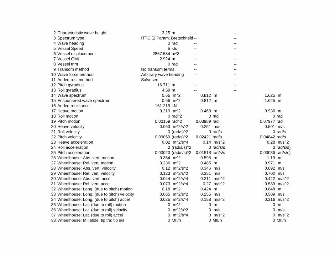
2 Characteristic wave height 3.25 m -- --3 Spectrum type ITTC (2 Param. Bretschneid -- --4 Wave heading 0 rad -- --5 Vessel Speed 5 kts -- --6 Vessel displacement 2867.584 m^3 -- --7 Vessel GMt 2.924 m -- --8 Vessel trim 0 rad -- --9 Transom method No transom terms -- --
10 Wave force method Arbitrary wave heading -- --11 Added res. method Salvesen -- --12 Pitch gyradius 16.711 m -- --13 Roll gyradius 4.58 m -- --14 Wave spectrum 0.66 m^2 0.812 m 1.625 m15 Encountered wave spectrum 0.66 m^2 0.812 m 1.625 m16 Added resistance 151.219 kN -- --17 Heave motion 0.219 m^2 0.468 m 0.936 m18 Roll motion 0 rad^2 0 rad 0 rad19 Pitch motion 0.00159 rad^2 0.03989 rad 0.07977 rad20 Heave velocity 0.063 m^2/s^2 0.251 m/s 0.501 m/s21 Roll velocity 0 (rad/s)^2 0 rad/s 0 rad/s22 Pitch velocity 0.00059 (rad/s)^2 0.02421 rad/s 0.04842 rad/s23 Heave acceleration 0.02 m^2/s^4 0.14 m/s^2 0.28 m/s^224 Roll acceleration 0 (rad/s/s)^2 0 rad/s/s 0 rad/s/s)25 Pitch acceleration 0.00023 (rad/s/s)^2 0.01518 rad/s/s 0.03036 rad/s/s)26 Wheelhouse: Abs. vert. motion 0.354 m^2 0.595 m 1.19 m27 Wheelhouse: Rel. vert. motion 0.236 m^2 0.485 m 0.971 m28 Wheelhouse: Abs. vert. velocity 0.12 m^2/s^2 0.346 m/s 0.692 m/s29 Wheelhouse: Rel. vert. velocity 0.123 m^2/s^2 0.351 m/s 0.702 m/s30 Wheelhouse: Abs. vert. accel 0.044 m^2/s^4 0.211 m/s^2 0.422 m/s^231 Wheelhouse: Rel. vert. accel 0.073 m^2/s^4 0.27 m/s^2 0.539 m/s^232 Wheelhouse: Long. (due to pitch) motion 0.18 m^2 0.424 m 0.848 m33 Wheelhouse: Long. (due to pitch) velocity 0.065 m^2/s^2 0.255 m/s 0.509 m/s34 Wheelhouse: Long. (due to pitch) accel 0.025 m^2/s^4 0.158 m/s^2 0.316 m/s^235 Wheelhouse: Lat. (due to roll) motion 0 m^2 0 m 0 m36 Wheelhouse: Lat. (due to roll) velocity 0 m^2/s^2 0 m/s 0 m/s37 Wheelhouse: Lat. (due to roll) accel 0 m^2/s^4 0 m/s^2 0 m/s^238 Wheelhouse: MII slide; tip f/a; tip s/s 0 MII/h 0 MII/h 0 MII/h

39 Workdeck: Abs. vert. motion 0.334 m^2 0.578 m 1.156 m40 Workdeck: Rel. vert. motion 0.201 m^2 0.448 m 0.896 m41 Workdeck: Abs. vert. velocity 0.1 m^2/s^2 0.317 m/s 0.634 m/s42 Workdeck: Rel. vert. velocity 0.127 m^2/s^2 0.356 m/s 0.712 m/s43 Workdeck: Abs. vert. accel 0.033 m^2/s^4 0.181 m/s^2 0.362 m/s^244 Workdeck: Rel. vert. accel 0.085 m^2/s^4 0.291 m/s^2 0.581 m/s^245 Workdeck: Long. (due to pitch) motion 0.022 m^2 0.148 m 0.296 m46 Workdeck: Long. (due to pitch) velocity 0.008 m^2/s^2 0.089 m/s 0.178 m/s47 Workdeck: Long. (due to pitch) accel 0.003 m^2/s^4 0.055 m/s^2 0.111 m/s^248 Workdeck: Lat. (due to roll) motion 0 m^2 0 m 0 m49 Workdeck: Lat. (due to roll) velocity 0 m^2/s^2 0 m/s 0 m/s50 Workdeck: Lat. (due to roll) accel 0 m^2/s^4 0 m/s^2 0 m/s^251 Workdeck: MII slide; tip f/a; tip s/s 0 MII/h 0 MII/h 0 MII/h
5, 5 kts; 0, 0 rad; Sea State 6 (ITTC (2 Param. Bretschneider): 12.4 s, 5 m)Item m0 units RMS units Significant amplitude units
1 Modal period 12.388 s -- --2 Characteristic wave height 5 m -- --3 Spectrum type ITTC (2 Param. Bretschneid -- --4 Wave heading 0 rad -- --5 Vessel Speed 5 kts -- --6 Vessel displacement 2867.584 m^3 -- --7 Vessel GMt 2.924 m -- --8 Vessel trim 0 rad -- --9 Transom method No transom terms -- --
10 Wave force method Arbitrary wave heading -- --11 Added res. method Salvesen -- --12 Pitch gyradius 16.711 m -- --13 Roll gyradius 4.58 m -- --14 Wave spectrum 1.563 m^2 1.25 m 2.5 m15 Encountered wave spectrum 1.562 m^2 1.25 m 2.5 m16 Added resistance 290.941 kN -- --17 Heave motion 0.88 m^2 0.938 m 1.877 m18 Roll motion 0 rad^2 0 rad 0 rad19 Pitch motion 0.00293 rad^2 0.05417 rad 0.10835 rad20 Heave velocity 0.192 m^2/s^2 0.438 m/s 0.876 m/s21 Roll velocity 0 (rad/s)^2 0 rad/s 0 rad/s22 Pitch velocity 0.00093 (rad/s)^2 0.03048 rad/s 0.06096 rad/s

23 Heave acceleration 0.047 m^2/s^4 0.216 m/s^2 0.433 m/s^224 Roll acceleration 0 (rad/s/s)^2 0 rad/s/s 0 rad/s/s)25 Pitch acceleration 0.00033 (rad/s/s)^2 0.01805 rad/s/s 0.03609 rad/s/s)26 Wheelhouse: Abs. vert. motion 1.043 m^2 1.021 m 2.043 m27 Wheelhouse: Rel. vert. motion 0.31 m^2 0.557 m 1.114 m28 Wheelhouse: Abs. vert. velocity 0.261 m^2/s^2 0.51 m/s 1.021 m/s29 Wheelhouse: Rel. vert. velocity 0.141 m^2/s^2 0.376 m/s 0.752 m/s30 Wheelhouse: Abs. vert. accel 0.076 m^2/s^4 0.276 m/s^2 0.552 m/s^231 Wheelhouse: Rel. vert. accel 0.076 m^2/s^4 0.276 m/s^2 0.552 m/s^232 Wheelhouse: Long. (due to pitch) motion 0.345 m^2 0.587 m 1.174 m33 Wheelhouse: Long. (due to pitch) velocity 0.106 m^2/s^2 0.326 m/s 0.652 m/s34 Wheelhouse: Long. (due to pitch) accel 0.036 m^2/s^4 0.191 m/s^2 0.381 m/s^235 Wheelhouse: Lat. (due to roll) motion 0 m^2 0 m 0 m36 Wheelhouse: Lat. (due to roll) velocity 0 m^2/s^2 0 m/s 0 m/s37 Wheelhouse: Lat. (due to roll) accel 0 m^2/s^4 0 m/s^2 0 m/s^238 Wheelhouse: MII slide; tip f/a; tip s/s 0 MII/h 0 MII/h 0 MII/h39 Workdeck: Abs. vert. motion 1.15 m^2 1.072 m 2.145 m40 Workdeck: Rel. vert. motion 0.202 m^2 0.449 m 0.898 m41 Workdeck: Abs. vert. velocity 0.265 m^2/s^2 0.515 m/s 1.031 m/s42 Workdeck: Rel. vert. velocity 0.124 m^2/s^2 0.353 m/s 0.705 m/s43 Workdeck: Abs. vert. accel 0.069 m^2/s^4 0.263 m/s^2 0.526 m/s^244 Workdeck: Rel. vert. accel 0.081 m^2/s^4 0.285 m/s^2 0.57 m/s^245 Workdeck: Long. (due to pitch) motion 0.042 m^2 0.205 m 0.411 m46 Workdeck: Long. (due to pitch) velocity 0.013 m^2/s^2 0.114 m/s 0.228 m/s47 Workdeck: Long. (due to pitch) accel 0.004 m^2/s^4 0.067 m/s^2 0.133 m/s^248 Workdeck: Lat. (due to roll) motion 0 m^2 0 m 0 m49 Workdeck: Lat. (due to roll) velocity 0 m^2/s^2 0 m/s 0 m/s50 Workdeck: Lat. (due to roll) accel 0 m^2/s^4 0 m/s^2 0 m/s^251 Workdeck: MII slide; tip f/a; tip s/s 0 MII/h 0 MII/h 0 MII/h
5, 5 kts; 30, 0.52 rad; Sea State 4 (ITTC (2 Param. Bretschneider): 8.8 s, 1.88 m)Item m0 units RMS units Significant amplitude units
1 Modal period 8.792 s -- --2 Characteristic wave height 1.88 m -- --3 Spectrum type ITTC (2 Param. Bretschneid -- --4 Wave heading 0.52 rad -- --5 Vessel Speed 5 kts -- --6 Vessel displacement 2867.584 m^3 -- --

7 Vessel GMt 2.924 m -- --8 Vessel trim 0 rad -- --9 Transom method No transom terms -- --
10 Wave force method Arbitrary wave heading -- --11 Added res. method Salvesen -- --12 Pitch gyradius 16.711 m -- --13 Roll gyradius 4.58 m -- --14 Wave spectrum 0.221 m^2 0.47 m 0.94 m15 Encountered wave spectrum 0.221 m^2 0.47 m 0.94 m16 Added resistance 54.636 kN -- --17 Heave motion 0.069 m^2 0.263 m 0.526 m18 Roll motion 0.00637 rad^2 0.07984 rad 0.15968 rad19 Pitch motion 0.00054 rad^2 0.02316 rad 0.04632 rad20 Heave velocity 0.024 m^2/s^2 0.156 m/s 0.312 m/s21 Roll velocity 0.00576 (rad/s)^2 0.07589 rad/s 0.15177 rad/s22 Pitch velocity 0.00023 (rad/s)^2 0.0153 rad/s 0.03061 rad/s23 Heave acceleration 0.009 m^2/s^4 0.097 m/s^2 0.194 m/s^224 Roll acceleration 0.0057 (rad/s/s)^2 0.07552 rad/s/s 0.15103 rad/s/s)25 Pitch acceleration 0.00011 (rad/s/s)^2 0.01045 rad/s/s 0.0209 rad/s/s)26 Wheelhouse: Abs. vert. motion 0.106 m^2 0.326 m 0.651 m27 Wheelhouse: Rel. vert. motion 0.082 m^2 0.286 m 0.571 m28 Wheelhouse: Abs. vert. velocity 0.044 m^2/s^2 0.21 m/s 0.42 m/s29 Wheelhouse: Rel. vert. velocity 0.052 m^2/s^2 0.228 m/s 0.455 m/s30 Wheelhouse: Abs. vert. accel 0.02 m^2/s^4 0.142 m/s^2 0.284 m/s^231 Wheelhouse: Rel. vert. accel 0.038 m^2/s^4 0.196 m/s^2 0.391 m/s^232 Wheelhouse: Long. (due to pitch) motion 0.06 m^2 0.245 m 0.491 m33 Wheelhouse: Long. (due to pitch) velocity 0.026 m^2/s^2 0.161 m/s 0.321 m/s34 Wheelhouse: Long. (due to pitch) accel 0.012 m^2/s^4 0.109 m/s^2 0.218 m/s^235 Wheelhouse: Lat. (due to roll) motion 0.778 m^2 0.882 m 1.764 m36 Wheelhouse: Lat. (due to roll) velocity 0.7 m^2/s^2 0.837 m/s 1.674 m/s37 Wheelhouse: Lat. (due to roll) accel 0.692 m^2/s^4 0.832 m/s^2 1.664 m/s^238 Wheelhouse: MII slide; tip f/a; tip s/s 0 MII/h 0 MII/h 0 MII/h39 Workdeck: Abs. vert. motion 0.186 m^2 0.431 m 0.862 m40 Workdeck: Rel. vert. motion 0.089 m^2 0.298 m 0.596 m41 Workdeck: Abs. vert. velocity 0.097 m^2/s^2 0.312 m/s 0.624 m/s42 Workdeck: Rel. vert. velocity 0.081 m^2/s^2 0.285 m/s 0.57 m/s43 Workdeck: Abs. vert. accel 0.068 m^2/s^4 0.261 m/s^2 0.521 m/s^2

44 Workdeck: Rel. vert. accel 0.081 m^2/s^4 0.285 m/s^2 0.57 m/s^245 Workdeck: Long. (due to pitch) motion 0.007 m^2 0.086 m 0.172 m46 Workdeck: Long. (due to pitch) velocity 0.003 m^2/s^2 0.056 m/s 0.112 m/s47 Workdeck: Long. (due to pitch) accel 0.001 m^2/s^4 0.038 m/s^2 0.076 m/s^248 Workdeck: Lat. (due to roll) motion 0.095 m^2 0.308 m 0.617 m49 Workdeck: Lat. (due to roll) velocity 0.086 m^2/s^2 0.293 m/s 0.585 m/s50 Workdeck: Lat. (due to roll) accel 0.085 m^2/s^4 0.291 m/s^2 0.582 m/s^251 Workdeck: MII slide; tip f/a; tip s/s 0 MII/h 0.276 MII/h 0.002 MII/h
5, 5 kts; 30, 0.52 rad; Sea State 5 (ITTC (2 Param. Bretschneider): 9.7 s, 3.25 m)Item m0 units RMS units Significant amplitude units
1 Modal period 9.691 s -- --2 Characteristic wave height 3.25 m -- --3 Spectrum type ITTC (2 Param. Bretschneid -- --4 Wave heading 0.52 rad -- --5 Vessel Speed 5 kts -- --6 Vessel displacement 2867.584 m^3 -- --7 Vessel GMt 2.924 m -- --8 Vessel trim 0 rad -- --9 Transom method No transom terms -- --
10 Wave force method Arbitrary wave heading -- --11 Added res. method Salvesen -- --12 Pitch gyradius 16.711 m -- --13 Roll gyradius 4.58 m -- --14 Wave spectrum 0.66 m^2 0.812 m 1.625 m15 Encountered wave spectrum 0.66 m^2 0.812 m 1.625 m16 Added resistance 152.617 kN -- --17 Heave motion 0.268 m^2 0.518 m 1.035 m18 Roll motion 0.01336 rad^2 0.11559 rad 0.23117 rad19 Pitch motion 0.00156 rad^2 0.03947 rad 0.07894 rad20 Heave velocity 0.085 m^2/s^2 0.291 m/s 0.582 m/s21 Roll velocity 0.01193 (rad/s)^2 0.10922 rad/s 0.21843 rad/s22 Pitch velocity 0.00064 (rad/s)^2 0.02528 rad/s 0.05056 rad/s23 Heave acceleration 0.03 m^2/s^4 0.172 m/s^2 0.344 m/s^224 Roll acceleration 0.01174 (rad/s/s)^2 0.10833 rad/s/s 0.21666 rad/s/s)25 Pitch acceleration 0.00028 (rad/s/s)^2 0.01683 rad/s/s 0.03366 rad/s/s)26 Wheelhouse: Abs. vert. motion 0.35 m^2 0.591 m 1.183 m27 Wheelhouse: Rel. vert. motion 0.201 m^2 0.449 m 0.898 m

28 Wheelhouse: Abs. vert. velocity 0.13 m^2/s^2 0.361 m/s 0.722 m/s29 Wheelhouse: Rel. vert. velocity 0.12 m^2/s^2 0.346 m/s 0.692 m/s30 Wheelhouse: Abs. vert. accel 0.055 m^2/s^4 0.234 m/s^2 0.467 m/s^231 Wheelhouse: Rel. vert. accel 0.084 m^2/s^4 0.29 m/s^2 0.581 m/s^232 Wheelhouse: Long. (due to pitch) motion 0.178 m^2 0.422 m 0.844 m33 Wheelhouse: Long. (due to pitch) velocity 0.072 m^2/s^2 0.267 m/s 0.535 m/s34 Wheelhouse: Long. (due to pitch) accel 0.031 m^2/s^4 0.176 m/s^2 0.353 m/s^235 Wheelhouse: Lat. (due to roll) motion 1.633 m^2 1.278 m 2.556 m36 Wheelhouse: Lat. (due to roll) velocity 1.452 m^2/s^2 1.205 m/s 2.41 m/s37 Wheelhouse: Lat. (due to roll) accel 1.425 m^2/s^4 1.194 m/s^2 2.387 m/s^238 Wheelhouse: MII slide; tip f/a; tip s/s 0 MII/h 0.002 MII/h 0 MII/h39 Workdeck: Abs. vert. motion 0.581 m^2 0.763 m 1.525 m40 Workdeck: Rel. vert. motion 0.189 m^2 0.435 m 0.869 m41 Workdeck: Abs. vert. velocity 0.258 m^2/s^2 0.508 m/s 1.017 m/s42 Workdeck: Rel. vert. velocity 0.169 m^2/s^2 0.411 m/s 0.822 m/s43 Workdeck: Abs. vert. accel 0.158 m^2/s^4 0.397 m/s^2 0.794 m/s^244 Workdeck: Rel. vert. accel 0.167 m^2/s^4 0.409 m/s^2 0.818 m/s^245 Workdeck: Long. (due to pitch) motion 0.022 m^2 0.148 m 0.295 m46 Workdeck: Long. (due to pitch) velocity 0.009 m^2/s^2 0.094 m/s 0.187 m/s47 Workdeck: Long. (due to pitch) accel 0.004 m^2/s^4 0.062 m/s^2 0.123 m/s^248 Workdeck: Lat. (due to roll) motion 0.2 m^2 0.447 m 0.894 m49 Workdeck: Lat. (due to roll) velocity 0.178 m^2/s^2 0.421 m/s 0.843 m/s50 Workdeck: Lat. (due to roll) accel 0.174 m^2/s^4 0.417 m/s^2 0.835 m/s^251 Workdeck: MII slide; tip f/a; tip s/s 0 MII/h 3.808 MII/h 0.306 MII/h
5, 5 kts; 30, 0.52 rad; Sea State 6 (ITTC (2 Param. Bretschneider): 12.4 s, 5 m)Item m0 units RMS units Significant amplitude units
1 Modal period 12.388 s -- --2 Characteristic wave height 5 m -- --3 Spectrum type ITTC (2 Param. Bretschneid -- --4 Wave heading 0.52 rad -- --5 Vessel Speed 5 kts -- --6 Vessel displacement 2867.584 m^3 -- --7 Vessel GMt 2.924 m -- --8 Vessel trim 0 rad -- --9 Transom method No transom terms -- --
10 Wave force method Arbitrary wave heading -- --11 Added res. method Salvesen -- --

12 Pitch gyradius 16.711 m -- --13 Roll gyradius 4.58 m -- --14 Wave spectrum 1.563 m^2 1.25 m 2.5 m15 Encountered wave spectrum 1.562 m^2 1.25 m 2.5 m16 Added resistance 294.492 kN -- --17 Heave motion 0.985 m^2 0.992 m 1.985 m18 Roll motion 0.01264 rad^2 0.11242 rad 0.22483 rad19 Pitch motion 0.00272 rad^2 0.05217 rad 0.10434 rad20 Heave velocity 0.233 m^2/s^2 0.483 m/s 0.966 m/s21 Roll velocity 0.01096 (rad/s)^2 0.10471 rad/s 0.20941 rad/s22 Pitch velocity 0.00096 (rad/s)^2 0.03094 rad/s 0.06189 rad/s23 Heave acceleration 0.063 m^2/s^4 0.251 m/s^2 0.503 m/s^224 Roll acceleration 0.01065 (rad/s/s)^2 0.1032 rad/s/s 0.2064 rad/s/s)25 Pitch acceleration 0.00038 (rad/s/s)^2 0.01946 rad/s/s 0.03892 rad/s/s)26 Wheelhouse: Abs. vert. motion 1.017 m^2 1.008 m 2.017 m27 Wheelhouse: Rel. vert. motion 0.26 m^2 0.51 m 1.02 m28 Wheelhouse: Abs. vert. velocity 0.272 m^2/s^2 0.521 m/s 1.043 m/s29 Wheelhouse: Rel. vert. velocity 0.135 m^2/s^2 0.367 m/s 0.734 m/s30 Wheelhouse: Abs. vert. accel 0.088 m^2/s^4 0.297 m/s^2 0.593 m/s^231 Wheelhouse: Rel. vert. accel 0.086 m^2/s^4 0.293 m/s^2 0.587 m/s^232 Wheelhouse: Long. (due to pitch) motion 0.323 m^2 0.569 m 1.137 m33 Wheelhouse: Long. (due to pitch) velocity 0.111 m^2/s^2 0.333 m/s 0.665 m/s34 Wheelhouse: Long. (due to pitch) accel 0.043 m^2/s^4 0.206 m/s^2 0.413 m/s^235 Wheelhouse: Lat. (due to roll) motion 1.551 m^2 1.246 m 2.491 m36 Wheelhouse: Lat. (due to roll) velocity 1.337 m^2/s^2 1.156 m/s 2.313 m/s37 Wheelhouse: Lat. (due to roll) accel 1.294 m^2/s^4 1.137 m/s^2 2.275 m/s^238 Wheelhouse: MII slide; tip f/a; tip s/s 0 MII/h 0.005 MII/h 0 MII/h39 Workdeck: Abs. vert. motion 1.515 m^2 1.231 m 2.461 m40 Workdeck: Rel. vert. motion 0.192 m^2 0.438 m 0.877 m41 Workdeck: Abs. vert. velocity 0.456 m^2/s^2 0.675 m/s 1.35 m/s42 Workdeck: Rel. vert. velocity 0.158 m^2/s^2 0.398 m/s 0.796 m/s43 Workdeck: Abs. vert. accel 0.198 m^2/s^4 0.445 m/s^2 0.89 m/s^244 Workdeck: Rel. vert. accel 0.152 m^2/s^4 0.39 m/s^2 0.78 m/s^245 Workdeck: Long. (due to pitch) motion 0.04 m^2 0.199 m 0.398 m46 Workdeck: Long. (due to pitch) velocity 0.014 m^2/s^2 0.116 m/s 0.233 m/s47 Workdeck: Long. (due to pitch) accel 0.005 m^2/s^4 0.072 m/s^2 0.144 m/s^248 Workdeck: Lat. (due to roll) motion 0.19 m^2 0.436 m 0.871 m
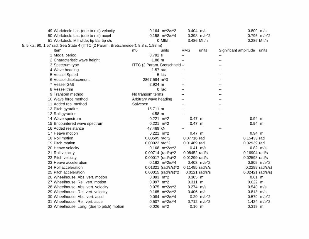
49 Workdeck: Lat. (due to roll) velocity 0.164 m^2/s^2 0.404 m/s 0.809 m/s50 Workdeck: Lat. (due to roll) accel 0.158 m^2/s^4 0.398 m/s^2 0.796 m/s^251 Workdeck: MII slide; tip f/a; tip s/s 0 MII/h 3.486 MII/h 0.286 MII/h
5, 5 kts; 90, 1.57 rad; Sea State 4 (ITTC (2 Param. Bretschneider): 8.8 s, 1.88 m)Item m0 units RMS units Significant amplitude units
1 Modal period 8.792 s -- --2 Characteristic wave height 1.88 m -- --3 Spectrum type ITTC (2 Param. Bretschneid -- --4 Wave heading 1.57 rad -- --5 Vessel Speed 5 kts -- --6 Vessel displacement 2867.584 m^3 -- --7 Vessel GMt 2.924 m -- --8 Vessel trim 0 rad -- --9 Transom method No transom terms -- --
10 Wave force method Arbitrary wave heading -- --11 Added res. method Salvesen -- --12 Pitch gyradius 16.711 m -- --13 Roll gyradius 4.58 m -- --14 Wave spectrum 0.221 m^2 0.47 m 0.94 m15 Encountered wave spectrum 0.221 m^2 0.47 m 0.94 m16 Added resistance 47.469 kN -- --17 Heave motion 0.221 m^2 0.47 m 0.94 m18 Roll motion 0.00595 rad^2 0.07716 rad 0.15433 rad19 Pitch motion 0.00022 rad^2 0.01469 rad 0.02939 rad20 Heave velocity 0.168 m^2/s^2 0.41 m/s 0.82 m/s21 Roll velocity 0.00714 (rad/s)^2 0.08452 rad/s 0.16904 rad/s22 Pitch velocity 0.00017 (rad/s)^2 0.01299 rad/s 0.02598 rad/s23 Heave acceleration 0.162 m^2/s^4 0.403 m/s^2 0.805 m/s^224 Roll acceleration 0.01321 (rad/s/s)^2 0.11495 rad/s/s 0.2299 rad/s/s)25 Pitch acceleration 0.00015 (rad/s/s)^2 0.0121 rad/s/s 0.02421 rad/s/s)26 Wheelhouse: Abs. vert. motion 0.093 m^2 0.305 m 0.61 m27 Wheelhouse: Rel. vert. motion 0.097 m^2 0.311 m 0.622 m28 Wheelhouse: Abs. vert. velocity 0.075 m^2/s^2 0.274 m/s 0.548 m/s29 Wheelhouse: Rel. vert. velocity 0.165 m^2/s^2 0.406 m/s 0.813 m/s30 Wheelhouse: Abs. vert. accel 0.084 m^2/s^4 0.29 m/s^2 0.579 m/s^231 Wheelhouse: Rel. vert. accel 0.507 m^2/s^4 0.712 m/s^2 1.424 m/s^232 Wheelhouse: Long. (due to pitch) motion 0.026 m^2 0.16 m 0.319 m

33 Wheelhouse: Long. (due to pitch) velocity 0.019 m^2/s^2 0.139 m/s 0.278 m/s34 Wheelhouse: Long. (due to pitch) accel 0.016 m^2/s^4 0.128 m/s^2 0.255 m/s^235 Wheelhouse: Lat. (due to roll) motion 0.728 m^2 0.853 m 1.706 m36 Wheelhouse: Lat. (due to roll) velocity 0.85 m^2/s^2 0.922 m/s 1.844 m/s37 Wheelhouse: Lat. (due to roll) accel 1.553 m^2/s^4 1.246 m/s^2 2.492 m/s^238 Wheelhouse: MII slide; tip f/a; tip s/s 0 MII/h 5.358 MII/h 0.379 MII/h39 Workdeck: Abs. vert. motion 0.517 m^2 0.719 m 1.438 m40 Workdeck: Rel. vert. motion 0.115 m^2 0.338 m 0.677 m41 Workdeck: Abs. vert. velocity 0.448 m^2/s^2 0.67 m/s 1.339 m/s42 Workdeck: Rel. vert. velocity 0.139 m^2/s^2 0.373 m/s 0.746 m/s43 Workdeck: Abs. vert. accel 0.516 m^2/s^4 0.718 m/s^2 1.437 m/s^244 Workdeck: Rel. vert. accel 0.395 m^2/s^4 0.628 m/s^2 1.257 m/s^245 Workdeck: Long. (due to pitch) motion 0.003 m^2 0.056 m 0.112 m46 Workdeck: Long. (due to pitch) velocity 0.002 m^2/s^2 0.049 m/s 0.097 m/s47 Workdeck: Long. (due to pitch) accel 0.002 m^2/s^4 0.045 m/s^2 0.089 m/s^248 Workdeck: Lat. (due to roll) motion 0.089 m^2 0.298 m 0.597 m49 Workdeck: Lat. (due to roll) velocity 0.104 m^2/s^2 0.323 m/s 0.645 m/s50 Workdeck: Lat. (due to roll) accel 0.19 m^2/s^4 0.436 m/s^2 0.872 m/s^251 Workdeck: MII slide; tip f/a; tip s/s 0 MII/h 0.167 MII/h 0.004 MII/h
5, 5 kts; 90, 1.57 rad; Sea State 5 (ITTC (2 Param. Bretschneider): 9.7 s, 3.25 m)Item m0 units RMS units Significant amplitude units
1 Modal period 9.691 s -- --2 Characteristic wave height 3.25 m -- --3 Spectrum type ITTC (2 Param. Bretschneid -- --4 Wave heading 1.57 rad -- --5 Vessel Speed 5 kts -- --6 Vessel displacement 2867.584 m^3 -- --7 Vessel GMt 2.924 m -- --8 Vessel trim 0 rad -- --9 Transom method No transom terms -- --
10 Wave force method Arbitrary wave heading -- --11 Added res. method Salvesen -- --12 Pitch gyradius 16.711 m -- --13 Roll gyradius 4.58 m -- --14 Wave spectrum 0.66 m^2 0.812 m 1.625 m15 Encountered wave spectrum 0.66 m^2 0.812 m 1.625 m16 Added resistance 138.649 kN -- --

17 Heave motion 0.673 m^2 0.821 m 1.641 m18 Roll motion 0.01403 rad^2 0.11844 rad 0.23688 rad19 Pitch motion 0.00056 rad^2 0.02375 rad 0.0475 rad20 Heave velocity 0.443 m^2/s^2 0.666 m/s 1.331 m/s21 Roll velocity 0.01595 (rad/s)^2 0.12629 rad/s 0.25257 rad/s22 Pitch velocity 0.00042 (rad/s)^2 0.02045 rad/s 0.0409 rad/s23 Heave acceleration 0.386 m^2/s^4 0.621 m/s^2 1.242 m/s^224 Roll acceleration 0.02812 (rad/s/s)^2 0.16768 rad/s/s 0.33537 rad/s/s)25 Pitch acceleration 0.00035 (rad/s/s)^2 0.01867 rad/s/s 0.03734 rad/s/s)26 Wheelhouse: Abs. vert. motion 0.307 m^2 0.554 m 1.107 m27 Wheelhouse: Rel. vert. motion 0.219 m^2 0.468 m 0.937 m28 Wheelhouse: Abs. vert. velocity 0.2 m^2/s^2 0.448 m/s 0.895 m/s29 Wheelhouse: Rel. vert. velocity 0.353 m^2/s^2 0.594 m/s 1.189 m/s30 Wheelhouse: Abs. vert. accel 0.195 m^2/s^4 0.442 m/s^2 0.883 m/s^231 Wheelhouse: Rel. vert. accel 1.048 m^2/s^4 1.024 m/s^2 2.047 m/s^232 Wheelhouse: Long. (due to pitch) motion 0.068 m^2 0.261 m 0.521 m33 Wheelhouse: Long. (due to pitch) velocity 0.049 m^2/s^2 0.22 m/s 0.441 m/s34 Wheelhouse: Long. (due to pitch) accel 0.039 m^2/s^4 0.198 m/s^2 0.396 m/s^235 Wheelhouse: Lat. (due to roll) motion 1.731 m^2 1.316 m 2.631 m36 Wheelhouse: Lat. (due to roll) velocity 1.91 m^2/s^2 1.382 m/s 2.764 m/s37 Wheelhouse: Lat. (due to roll) accel 3.312 m^2/s^4 1.82 m/s^2 3.64 m/s^238 Wheelhouse: MII slide; tip f/a; tip s/s 0 MII/h 17.647 MII/h 4.866 MII/h39 Workdeck: Abs. vert. motion 1.433 m^2 1.197 m 2.394 m40 Workdeck: Rel. vert. motion 0.285 m^2 0.534 m 1.068 m41 Workdeck: Abs. vert. velocity 1.107 m^2/s^2 1.052 m/s 2.104 m/s42 Workdeck: Rel. vert. velocity 0.315 m^2/s^2 0.562 m/s 1.123 m/s43 Workdeck: Abs. vert. accel 1.172 m^2/s^4 1.083 m/s^2 2.165 m/s^244 Workdeck: Rel. vert. accel 0.827 m^2/s^4 0.909 m/s^2 1.818 m/s^245 Workdeck: Long. (due to pitch) motion 0.008 m^2 0.091 m 0.182 m46 Workdeck: Long. (due to pitch) velocity 0.006 m^2/s^2 0.077 m/s 0.154 m/s47 Workdeck: Long. (due to pitch) accel 0.005 m^2/s^4 0.069 m/s^2 0.138 m/s^248 Workdeck: Lat. (due to roll) motion 0.212 m^2 0.46 m 0.92 m49 Workdeck: Lat. (due to roll) velocity 0.234 m^2/s^2 0.483 m/s 0.967 m/s50 Workdeck: Lat. (due to roll) accel 0.405 m^2/s^4 0.637 m/s^2 1.273 m/s^251 Workdeck: MII slide; tip f/a; tip s/s 0 MII/h 2.48 MII/h 0.411 MII/h
5, 5 kts; 90, 1.57 rad; Sea State 6 (ITTC (2 Param. Bretschneider): 12.4 s, 5 m)Item m0 units RMS units Significant amplitude units

1 Modal period 12.388 s -- --2 Characteristic wave height 5 m -- --3 Spectrum type ITTC (2 Param. Bretschneid -- --4 Wave heading 1.57 rad -- --5 Vessel Speed 5 kts -- --6 Vessel displacement 2867.584 m^3 -- --7 Vessel GMt 2.924 m -- --8 Vessel trim 0 rad -- --9 Transom method No transom terms -- --
10 Wave force method Arbitrary wave heading -- --11 Added res. method Salvesen -- --12 Pitch gyradius 16.711 m -- --13 Roll gyradius 4.58 m -- --14 Wave spectrum 1.563 m^2 1.25 m 2.5 m15 Encountered wave spectrum 1.563 m^2 1.25 m 2.5 m16 Added resistance 290.756 kN -- --17 Heave motion 1.617 m^2 1.272 m 2.543 m18 Roll motion 0.01621 rad^2 0.1273 rad 0.2546 rad19 Pitch motion 0.00077 rad^2 0.02772 rad 0.05544 rad20 Heave velocity 0.717 m^2/s^2 0.847 m/s 1.693 m/s21 Roll velocity 0.01651 (rad/s)^2 0.1285 rad/s 0.25699 rad/s22 Pitch velocity 0.00051 (rad/s)^2 0.02259 rad/s 0.04517 rad/s23 Heave acceleration 0.472 m^2/s^4 0.687 m/s^2 1.374 m/s^224 Roll acceleration 0.02685 (rad/s/s)^2 0.16386 rad/s/s 0.32772 rad/s/s)25 Pitch acceleration 0.00039 (rad/s/s)^2 0.01985 rad/s/s 0.0397 rad/s/s)26 Wheelhouse: Abs. vert. motion 0.96 m^2 0.98 m 1.959 m27 Wheelhouse: Rel. vert. motion 0.242 m^2 0.492 m 0.984 m28 Wheelhouse: Abs. vert. velocity 0.371 m^2/s^2 0.609 m/s 1.219 m/s29 Wheelhouse: Rel. vert. velocity 0.344 m^2/s^2 0.586 m/s 1.173 m/s30 Wheelhouse: Abs. vert. accel 0.241 m^2/s^4 0.491 m/s^2 0.981 m/s^231 Wheelhouse: Rel. vert. accel 0.958 m^2/s^4 0.979 m/s^2 1.957 m/s^232 Wheelhouse: Long. (due to pitch) motion 0.097 m^2 0.311 m 0.622 m33 Wheelhouse: Long. (due to pitch) velocity 0.061 m^2/s^2 0.247 m/s 0.494 m/s34 Wheelhouse: Long. (due to pitch) accel 0.045 m^2/s^4 0.212 m/s^2 0.425 m/s^235 Wheelhouse: Lat. (due to roll) motion 2.039 m^2 1.428 m 2.856 m36 Wheelhouse: Lat. (due to roll) velocity 2 m^2/s^2 1.414 m/s 2.828 m/s37 Wheelhouse: Lat. (due to roll) accel 3.176 m^2/s^4 1.782 m/s^2 3.564 m/s^2

38 Wheelhouse: MII slide; tip f/a; tip s/s 0 MII/h 16.078 MII/h 4.14 MII/h39 Workdeck: Abs. vert. motion 2.693 m^2 1.641 m 3.282 m40 Workdeck: Rel. vert. motion 0.391 m^2 0.625 m 1.251 m41 Workdeck: Abs. vert. velocity 1.495 m^2/s^2 1.223 m/s 2.445 m/s42 Workdeck: Rel. vert. velocity 0.345 m^2/s^2 0.587 m/s 1.174 m/s43 Workdeck: Abs. vert. accel 1.285 m^2/s^4 1.134 m/s^2 2.267 m/s^244 Workdeck: Rel. vert. accel 0.775 m^2/s^4 0.88 m/s^2 1.76 m/s^245 Workdeck: Long. (due to pitch) motion 0.012 m^2 0.109 m 0.218 m46 Workdeck: Long. (due to pitch) velocity 0.007 m^2/s^2 0.086 m/s 0.173 m/s47 Workdeck: Long. (due to pitch) accel 0.006 m^2/s^4 0.074 m/s^2 0.149 m/s^248 Workdeck: Lat. (due to roll) motion 0.249 m^2 0.499 m 0.999 m49 Workdeck: Lat. (due to roll) velocity 0.245 m^2/s^2 0.495 m/s 0.989 m/s50 Workdeck: Lat. (due to roll) accel 0.388 m^2/s^4 0.623 m/s^2 1.247 m/s^251 Workdeck: MII slide; tip f/a; tip s/s 0 MII/h 3.384 MII/h 0.716 MII/h
5, 5 kts; 140, 2.44 rad; Sea State 4 (ITTC (2 Param. Bretschneider): 8.8 s, 1.88 m)Item m0 units RMS units Significant amplitude units
1 Modal period 8.792 s -- --2 Characteristic wave height 1.88 m -- --3 Spectrum type ITTC (2 Param. Bretschneid -- --4 Wave heading 2.44 rad -- --5 Vessel Speed 5 kts -- --6 Vessel displacement 2867.584 m^3 -- --7 Vessel GMt 2.924 m -- --8 Vessel trim 0 rad -- --9 Transom method No transom terms -- --
10 Wave force method Arbitrary wave heading -- --11 Added res. method Salvesen -- --12 Pitch gyradius 16.711 m -- --13 Roll gyradius 4.58 m -- --14 Wave spectrum 0.221 m^2 0.47 m 0.94 m15 Encountered wave spectrum 0.221 m^2 0.47 m 0.94 m16 Added resistance 54.728 kN -- --17 Heave motion 0.145 m^2 0.381 m 0.762 m18 Roll motion 0.00179 rad^2 0.04227 rad 0.08454 rad19 Pitch motion 0.0005 rad^2 0.02243 rad 0.04486 rad20 Heave velocity 0.114 m^2/s^2 0.338 m/s 0.675 m/s21 Roll velocity 0.00224 (rad/s)^2 0.04737 rad/s 0.09475 rad/s

22 Pitch velocity 0.00053 (rad/s)^2 0.02295 rad/s 0.0459 rad/s23 Heave acceleration 0.104 m^2/s^4 0.322 m/s^2 0.645 m/s^224 Roll acceleration 0.00425 (rad/s/s)^2 0.0652 rad/s/s 0.1304 rad/s/s)25 Pitch acceleration 0.00063 (rad/s/s)^2 0.02505 rad/s/s 0.0501 rad/s/s)26 Wheelhouse: Abs. vert. motion 0.267 m^2 0.517 m 1.034 m27 Wheelhouse: Rel. vert. motion 0.116 m^2 0.341 m 0.682 m28 Wheelhouse: Abs. vert. velocity 0.238 m^2/s^2 0.488 m/s 0.977 m/s29 Wheelhouse: Rel. vert. velocity 0.253 m^2/s^2 0.503 m/s 1.006 m/s30 Wheelhouse: Abs. vert. accel 0.243 m^2/s^4 0.493 m/s^2 0.987 m/s^231 Wheelhouse: Rel. vert. accel 0.986 m^2/s^4 0.993 m/s^2 1.986 m/s^232 Wheelhouse: Long. (due to pitch) motion 0.06 m^2 0.246 m 0.491 m33 Wheelhouse: Long. (due to pitch) velocity 0.063 m^2/s^2 0.251 m/s 0.501 m/s34 Wheelhouse: Long. (due to pitch) accel 0.075 m^2/s^4 0.273 m/s^2 0.546 m/s^235 Wheelhouse: Lat. (due to roll) motion 0.215 m^2 0.464 m 0.927 m36 Wheelhouse: Lat. (due to roll) velocity 0.268 m^2/s^2 0.518 m/s 1.036 m/s37 Wheelhouse: Lat. (due to roll) accel 0.503 m^2/s^4 0.709 m/s^2 1.418 m/s^238 Wheelhouse: MII slide; tip f/a; tip s/s 0 MII/h 0.04 MII/h 0 MII/h39 Workdeck: Abs. vert. motion 0.207 m^2 0.455 m 0.909 m40 Workdeck: Rel. vert. motion 0.057 m^2 0.238 m 0.477 m41 Workdeck: Abs. vert. velocity 0.179 m^2/s^2 0.423 m/s 0.845 m/s42 Workdeck: Rel. vert. velocity 0.168 m^2/s^2 0.41 m/s 0.82 m/s43 Workdeck: Abs. vert. accel 0.189 m^2/s^4 0.435 m/s^2 0.871 m/s^244 Workdeck: Rel. vert. accel 0.99 m^2/s^4 0.995 m/s^2 1.99 m/s^245 Workdeck: Long. (due to pitch) motion 0.007 m^2 0.086 m 0.172 m46 Workdeck: Long. (due to pitch) velocity 0.008 m^2/s^2 0.088 m/s 0.175 m/s47 Workdeck: Long. (due to pitch) accel 0.009 m^2/s^4 0.095 m/s^2 0.191 m/s^248 Workdeck: Lat. (due to roll) motion 0.026 m^2 0.162 m 0.324 m49 Workdeck: Lat. (due to roll) velocity 0.033 m^2/s^2 0.181 m/s 0.362 m/s50 Workdeck: Lat. (due to roll) accel 0.061 m^2/s^4 0.248 m/s^2 0.496 m/s^251 Workdeck: MII slide; tip f/a; tip s/s 0 MII/h 0 MII/h 0 MII/h
5, 5 kts; 140, 2.44 rad; Sea State 5 (ITTC (2 Param. Bretschneider): 9.7 s, 3.25 m)Item m0 units RMS units Significant amplitude units
1 Modal period 9.691 s -- --2 Characteristic wave height 3.25 m -- --3 Spectrum type ITTC (2 Param. Bretschneid -- --4 Wave heading 2.44 rad -- --5 Vessel Speed 5 kts -- --

6 Vessel displacement 2867.584 m^3 -- --7 Vessel GMt 2.924 m -- --8 Vessel trim 0 rad -- --9 Transom method No transom terms -- --
10 Wave force method Arbitrary wave heading -- --11 Added res. method Salvesen -- --12 Pitch gyradius 16.711 m -- --13 Roll gyradius 4.58 m -- --14 Wave spectrum 0.66 m^2 0.812 m 1.625 m15 Encountered wave spectrum 0.66 m^2 0.812 m 1.625 m16 Added resistance 160.574 kN -- --17 Heave motion 0.491 m^2 0.701 m 1.401 m18 Roll motion 0.00452 rad^2 0.06725 rad 0.13451 rad19 Pitch motion 0.00135 rad^2 0.03674 rad 0.07348 rad20 Heave velocity 0.338 m^2/s^2 0.581 m/s 1.163 m/s21 Roll velocity 0.00534 (rad/s)^2 0.07307 rad/s 0.14614 rad/s22 Pitch velocity 0.00132 (rad/s)^2 0.03634 rad/s 0.07269 rad/s23 Heave acceleration 0.279 m^2/s^4 0.529 m/s^2 1.057 m/s^224 Roll acceleration 0.00944 (rad/s/s)^2 0.09715 rad/s/s 0.19429 rad/s/s)25 Pitch acceleration 0.0015 (rad/s/s)^2 0.03874 rad/s/s 0.07748 rad/s/s)26 Wheelhouse: Abs. vert. motion 0.815 m^2 0.903 m 1.805 m27 Wheelhouse: Rel. vert. motion 0.26 m^2 0.51 m 1.019 m28 Wheelhouse: Abs. vert. velocity 0.651 m^2/s^2 0.807 m/s 1.613 m/s29 Wheelhouse: Rel. vert. velocity 0.547 m^2/s^2 0.74 m/s 1.479 m/s30 Wheelhouse: Abs. vert. accel 0.617 m^2/s^4 0.785 m/s^2 1.571 m/s^231 Wheelhouse: Rel. vert. accel 2.061 m^2/s^4 1.436 m/s^2 2.871 m/s^232 Wheelhouse: Long. (due to pitch) motion 0.162 m^2 0.403 m 0.806 m33 Wheelhouse: Long. (due to pitch) velocity 0.158 m^2/s^2 0.397 m/s 0.795 m/s34 Wheelhouse: Long. (due to pitch) accel 0.179 m^2/s^4 0.423 m/s^2 0.845 m/s^235 Wheelhouse: Lat. (due to roll) motion 0.546 m^2 0.739 m 1.477 m36 Wheelhouse: Lat. (due to roll) velocity 0.639 m^2/s^2 0.799 m/s 1.599 m/s37 Wheelhouse: Lat. (due to roll) accel 1.118 m^2/s^4 1.057 m/s^2 2.114 m/s^238 Wheelhouse: MII slide; tip f/a; tip s/s 0 MII/h 1.371 MII/h 0.05 MII/h39 Workdeck: Abs. vert. motion 0.655 m^2 0.809 m 1.619 m40 Workdeck: Rel. vert. motion 0.13 m^2 0.36 m 0.72 m41 Workdeck: Abs. vert. velocity 0.499 m^2/s^2 0.707 m/s 1.413 m/s42 Workdeck: Rel. vert. velocity 0.357 m^2/s^2 0.597 m/s 1.194 m/s

43 Workdeck: Abs. vert. accel 0.481 m^2/s^4 0.693 m/s^2 1.386 m/s^244 Workdeck: Rel. vert. accel 2.041 m^2/s^4 1.429 m/s^2 2.857 m/s^245 Workdeck: Long. (due to pitch) motion 0.02 m^2 0.141 m 0.282 m46 Workdeck: Long. (due to pitch) velocity 0.019 m^2/s^2 0.139 m/s 0.278 m/s47 Workdeck: Long. (due to pitch) accel 0.022 m^2/s^4 0.148 m/s^2 0.296 m/s^248 Workdeck: Lat. (due to roll) motion 0.067 m^2 0.258 m 0.517 m49 Workdeck: Lat. (due to roll) velocity 0.078 m^2/s^2 0.28 m/s 0.559 m/s50 Workdeck: Lat. (due to roll) accel 0.137 m^2/s^4 0.37 m/s^2 0.74 m/s^251 Workdeck: MII slide; tip f/a; tip s/s 0 MII/h 0.044 MII/h 0.001 MII/h
5, 5 kts; 140, 2.44 rad; Sea State 6 (ITTC (2 Param. Bretschneider): 12.4 s, 5 m)Item m0 units RMS units Significant amplitude units
1 Modal period 12.388 s -- --2 Characteristic wave height 5 m -- --3 Spectrum type ITTC (2 Param. Bretschneid -- --4 Wave heading 2.44 rad -- --5 Vessel Speed 5 kts -- --6 Vessel displacement 2867.584 m^3 -- --7 Vessel GMt 2.924 m -- --8 Vessel trim 0 rad -- --9 Transom method No transom terms -- --
10 Wave force method Arbitrary wave heading -- --11 Added res. method Salvesen -- --12 Pitch gyradius 16.711 m -- --13 Roll gyradius 4.58 m -- --14 Wave spectrum 1.563 m^2 1.25 m 2.5 m15 Encountered wave spectrum 1.563 m^2 1.25 m 2.5 m16 Added resistance 328.089 kN -- --17 Heave motion 1.384 m^2 1.176 m 2.353 m18 Roll motion 0.00582 rad^2 0.07627 rad 0.15255 rad19 Pitch motion 0.002 rad^2 0.04476 rad 0.08952 rad20 Heave velocity 0.659 m^2/s^2 0.812 m/s 1.623 m/s21 Roll velocity 0.00608 (rad/s)^2 0.07801 rad/s 0.15601 rad/s22 Pitch velocity 0.00167 (rad/s)^2 0.04081 rad/s 0.08162 rad/s23 Heave acceleration 0.418 m^2/s^4 0.647 m/s^2 1.293 m/s^224 Roll acceleration 0.00963 (rad/s/s)^2 0.09813 rad/s/s 0.19626 rad/s/s)25 Pitch acceleration 0.00171 (rad/s/s)^2 0.0414 rad/s/s 0.08279 rad/s/s)26 Wheelhouse: Abs. vert. motion 1.843 m^2 1.358 m 2.715 m

27 Wheelhouse: Rel. vert. motion 0.267 m^2 0.517 m 1.034 m28 Wheelhouse: Abs. vert. velocity 1.049 m^2/s^2 1.024 m/s 2.049 m/s29 Wheelhouse: Rel. vert. velocity 0.532 m^2/s^2 0.729 m/s 1.458 m/s30 Wheelhouse: Abs. vert. accel 0.808 m^2/s^4 0.899 m/s^2 1.798 m/s^231 Wheelhouse: Rel. vert. accel 1.907 m^2/s^4 1.381 m/s^2 2.762 m/s^232 Wheelhouse: Long. (due to pitch) motion 0.243 m^2 0.492 m 0.985 m33 Wheelhouse: Long. (due to pitch) velocity 0.2 m^2/s^2 0.447 m/s 0.894 m/s34 Wheelhouse: Long. (due to pitch) accel 0.204 m^2/s^4 0.452 m/s^2 0.904 m/s^235 Wheelhouse: Lat. (due to roll) motion 0.707 m^2 0.841 m 1.681 m36 Wheelhouse: Lat. (due to roll) velocity 0.731 m^2/s^2 0.855 m/s 1.71 m/s37 Wheelhouse: Lat. (due to roll) accel 1.143 m^2/s^4 1.069 m/s^2 2.139 m/s^238 Wheelhouse: MII slide; tip f/a; tip s/s 0 MII/h 1.226 MII/h 0.04 MII/h39 Workdeck: Abs. vert. motion 1.626 m^2 1.275 m 2.551 m40 Workdeck: Rel. vert. motion 0.153 m^2 0.391 m 0.783 m41 Workdeck: Abs. vert. velocity 0.862 m^2/s^2 0.928 m/s 1.857 m/s42 Workdeck: Rel. vert. velocity 0.344 m^2/s^2 0.587 m/s 1.173 m/s43 Workdeck: Abs. vert. accel 0.643 m^2/s^4 0.802 m/s^2 1.604 m/s^244 Workdeck: Rel. vert. accel 1.854 m^2/s^4 1.362 m/s^2 2.723 m/s^245 Workdeck: Long. (due to pitch) motion 0.03 m^2 0.172 m 0.344 m46 Workdeck: Long. (due to pitch) velocity 0.024 m^2/s^2 0.156 m/s 0.313 m/s47 Workdeck: Long. (due to pitch) accel 0.025 m^2/s^4 0.158 m/s^2 0.316 m/s^248 Workdeck: Lat. (due to roll) motion 0.086 m^2 0.294 m 0.588 m49 Workdeck: Lat. (due to roll) velocity 0.089 m^2/s^2 0.299 m/s 0.598 m/s50 Workdeck: Lat. (due to roll) accel 0.14 m^2/s^4 0.374 m/s^2 0.748 m/s^251 Workdeck: MII slide; tip f/a; tip s/s 0 MII/h 0.198 MII/h 0.01 MII/h
5, 5 kts; 180, 3.142 rad; Sea State 4 (ITTC (2 Param. Bretschneider): 8.8 s, 1.88 m)Item m0 units RMS units Significant amplitude units
1 Modal period 8.792 s -- --2 Characteristic wave height 1.88 m -- --3 Spectrum type ITTC (2 Param. Bretschneid -- --4 Wave heading 3.142 rad -- --5 Vessel Speed 5 kts -- --6 Vessel displacement 2867.584 m^3 -- --7 Vessel GMt 2.924 m -- --8 Vessel trim 0 rad -- --9 Transom method No transom terms -- --
10 Wave force method Arbitrary wave heading -- --

11 Added res. method Salvesen -- --12 Pitch gyradius 16.711 m -- --13 Roll gyradius 4.58 m -- --14 Wave spectrum 0.221 m^2 0.47 m 0.94 m15 Encountered wave spectrum 0.221 m^2 0.47 m 0.94 m16 Added resistance 46.965 kN -- --17 Heave motion 0.102 m^2 0.32 m 0.64 m18 Roll motion 0 rad^2 0 rad 0 rad19 Pitch motion 0.00041 rad^2 0.02022 rad 0.04044 rad20 Heave velocity 0.078 m^2/s^2 0.279 m/s 0.559 m/s21 Roll velocity 0 (rad/s)^2 0 rad/s 0 rad/s22 Pitch velocity 0.00039 (rad/s)^2 0.01965 rad/s 0.03931 rad/s23 Heave acceleration 0.068 m^2/s^4 0.261 m/s^2 0.522 m/s^224 Roll acceleration 0 (rad/s/s)^2 0 rad/s/s 0 rad/s/s)25 Pitch acceleration 0.00041 (rad/s/s)^2 0.02021 rad/s/s 0.04042 rad/s/s)26 Wheelhouse: Abs. vert. motion 0.243 m^2 0.493 m 0.986 m27 Wheelhouse: Rel. vert. motion 0.134 m^2 0.366 m 0.731 m28 Wheelhouse: Abs. vert. velocity 0.21 m^2/s^2 0.458 m/s 0.917 m/s29 Wheelhouse: Rel. vert. velocity 0.273 m^2/s^2 0.522 m/s 1.045 m/s30 Wheelhouse: Abs. vert. accel 0.206 m^2/s^4 0.453 m/s^2 0.907 m/s^231 Wheelhouse: Rel. vert. accel 1.083 m^2/s^4 1.041 m/s^2 2.082 m/s^232 Wheelhouse: Long. (due to pitch) motion 0.049 m^2 0.221 m 0.442 m33 Wheelhouse: Long. (due to pitch) velocity 0.046 m^2/s^2 0.214 m/s 0.428 m/s34 Wheelhouse: Long. (due to pitch) accel 0.048 m^2/s^4 0.22 m/s^2 0.44 m/s^235 Wheelhouse: Lat. (due to roll) motion 0 m^2 0 m 0 m36 Wheelhouse: Lat. (due to roll) velocity 0 m^2/s^2 0 m/s 0 m/s37 Wheelhouse: Lat. (due to roll) accel 0 m^2/s^4 0 m/s^2 0 m/s^238 Wheelhouse: MII slide; tip f/a; tip s/s 0 MII/h 0 MII/h 0 MII/h39 Workdeck: Abs. vert. motion 0.082 m^2 0.287 m 0.574 m40 Workdeck: Rel. vert. motion 0.089 m^2 0.299 m 0.597 m41 Workdeck: Abs. vert. velocity 0.059 m^2/s^2 0.243 m/s 0.487 m/s42 Workdeck: Rel. vert. velocity 0.251 m^2/s^2 0.501 m/s 1.001 m/s43 Workdeck: Abs. vert. accel 0.049 m^2/s^4 0.222 m/s^2 0.443 m/s^244 Workdeck: Rel. vert. accel 1.373 m^2/s^4 1.172 m/s^2 2.343 m/s^245 Workdeck: Long. (due to pitch) motion 0.006 m^2 0.077 m 0.154 m46 Workdeck: Long. (due to pitch) velocity 0.006 m^2/s^2 0.075 m/s 0.15 m/s47 Workdeck: Long. (due to pitch) accel 0.006 m^2/s^4 0.077 m/s^2 0.154 m/s^2

48 Workdeck: Lat. (due to roll) motion 0 m^2 0 m 0 m49 Workdeck: Lat. (due to roll) velocity 0 m^2/s^2 0 m/s 0 m/s50 Workdeck: Lat. (due to roll) accel 0 m^2/s^4 0 m/s^2 0 m/s^251 Workdeck: MII slide; tip f/a; tip s/s 0 MII/h 0 MII/h 0 MII/h
5, 5 kts; 180, 3.142 rad; Sea State 5 (ITTC (2 Param. Bretschneider): 9.7 s, 3.25 m)Item m0 units RMS units Significant amplitude units
1 Modal period 9.691 s -- --2 Characteristic wave height 3.25 m -- --3 Spectrum type ITTC (2 Param. Bretschneid -- --4 Wave heading 3.142 rad -- --5 Vessel Speed 5 kts -- --6 Vessel displacement 2867.584 m^3 -- --7 Vessel GMt 2.924 m -- --8 Vessel trim 0 rad -- --9 Transom method No transom terms -- --
10 Wave force method Arbitrary wave heading -- --11 Added res. method Salvesen -- --12 Pitch gyradius 16.711 m -- --13 Roll gyradius 4.58 m -- --14 Wave spectrum 0.66 m^2 0.812 m 1.625 m15 Encountered wave spectrum 0.66 m^2 0.812 m 1.625 m16 Added resistance 142.863 kN -- --17 Heave motion 0.37 m^2 0.609 m 1.217 m18 Roll motion 0 rad^2 0 rad 0 rad19 Pitch motion 0.0012 rad^2 0.03466 rad 0.06931 rad20 Heave velocity 0.248 m^2/s^2 0.498 m/s 0.995 m/s21 Roll velocity 0 (rad/s)^2 0 rad/s 0 rad/s22 Pitch velocity 0.00105 (rad/s)^2 0.03239 rad/s 0.06478 rad/s23 Heave acceleration 0.195 m^2/s^4 0.442 m/s^2 0.883 m/s^224 Roll acceleration 0 (rad/s/s)^2 0 rad/s/s 0 rad/s/s)25 Pitch acceleration 0.00105 (rad/s/s)^2 0.03236 rad/s/s 0.06473 rad/s/s)26 Wheelhouse: Abs. vert. motion 0.782 m^2 0.884 m 1.768 m27 Wheelhouse: Rel. vert. motion 0.313 m^2 0.56 m 1.119 m28 Wheelhouse: Abs. vert. velocity 0.606 m^2/s^2 0.779 m/s 1.557 m/s29 Wheelhouse: Rel. vert. velocity 0.604 m^2/s^2 0.777 m/s 1.554 m/s30 Wheelhouse: Abs. vert. accel 0.549 m^2/s^4 0.741 m/s^2 1.482 m/s^231 Wheelhouse: Rel. vert. accel 2.258 m^2/s^4 1.503 m/s^2 3.006 m/s^2

32 Wheelhouse: Long. (due to pitch) motion 0.144 m^2 0.379 m 0.758 m33 Wheelhouse: Long. (due to pitch) velocity 0.125 m^2/s^2 0.353 m/s 0.707 m/s34 Wheelhouse: Long. (due to pitch) accel 0.124 m^2/s^4 0.352 m/s^2 0.705 m/s^235 Wheelhouse: Lat. (due to roll) motion 0 m^2 0 m 0 m36 Wheelhouse: Lat. (due to roll) velocity 0 m^2/s^2 0 m/s 0 m/s37 Wheelhouse: Lat. (due to roll) accel 0 m^2/s^4 0 m/s^2 0 m/s^238 Wheelhouse: MII slide; tip f/a; tip s/s 0 MII/h 0 MII/h 0 MII/h39 Workdeck: Abs. vert. motion 0.313 m^2 0.559 m 1.118 m40 Workdeck: Rel. vert. motion 0.2 m^2 0.447 m 0.895 m41 Workdeck: Abs. vert. velocity 0.197 m^2/s^2 0.444 m/s 0.887 m/s42 Workdeck: Rel. vert. velocity 0.535 m^2/s^2 0.732 m/s 1.463 m/s43 Workdeck: Abs. vert. accel 0.146 m^2/s^4 0.382 m/s^2 0.764 m/s^244 Workdeck: Rel. vert. accel 2.823 m^2/s^4 1.68 m/s^2 3.361 m/s^245 Workdeck: Long. (due to pitch) motion 0.018 m^2 0.133 m 0.265 m46 Workdeck: Long. (due to pitch) velocity 0.015 m^2/s^2 0.124 m/s 0.247 m/s47 Workdeck: Long. (due to pitch) accel 0.015 m^2/s^4 0.123 m/s^2 0.246 m/s^248 Workdeck: Lat. (due to roll) motion 0 m^2 0 m 0 m49 Workdeck: Lat. (due to roll) velocity 0 m^2/s^2 0 m/s 0 m/s50 Workdeck: Lat. (due to roll) accel 0 m^2/s^4 0 m/s^2 0 m/s^251 Workdeck: MII slide; tip f/a; tip s/s 0 MII/h 0 MII/h 0 MII/h
5, 5 kts; 180, 3.142 rad; Sea State 6 (ITTC (2 Param. Bretschneider): 12.4 s, 5 m)Item m0 units RMS units Significant amplitude units
1 Modal period 12.388 s -- --2 Characteristic wave height 5 m -- --3 Spectrum type ITTC (2 Param. Bretschneid -- --4 Wave heading 3.142 rad -- --5 Vessel Speed 5 kts -- --6 Vessel displacement 2867.584 m^3 -- --7 Vessel GMt 2.924 m -- --8 Vessel trim 0 rad -- --9 Transom method No transom terms -- --
10 Wave force method Arbitrary wave heading -- --11 Added res. method Salvesen -- --12 Pitch gyradius 16.711 m -- --13 Roll gyradius 4.58 m -- --14 Wave spectrum 1.563 m^2 1.25 m 2.5 m15 Encountered wave spectrum 1.563 m^2 1.25 m 2.5 m

16 Added resistance 308.117 kN -- --17 Heave motion 1.183 m^2 1.088 m 2.175 m18 Roll motion 0 rad^2 0 rad 0 rad19 Pitch motion 0.00212 rad^2 0.04604 rad 0.09207 rad20 Heave velocity 0.548 m^2/s^2 0.74 m/s 1.48 m/s21 Roll velocity 0 (rad/s)^2 0 rad/s 0 rad/s22 Pitch velocity 0.00153 (rad/s)^2 0.03907 rad/s 0.07813 rad/s23 Heave acceleration 0.328 m^2/s^4 0.573 m/s^2 1.145 m/s^224 Roll acceleration 0 (rad/s/s)^2 0 rad/s/s 0 rad/s/s)25 Pitch acceleration 0.00134 (rad/s/s)^2 0.03665 rad/s/s 0.0733 rad/s/s)26 Wheelhouse: Abs. vert. motion 1.899 m^2 1.378 m 2.756 m27 Wheelhouse: Rel. vert. motion 0.348 m^2 0.59 m 1.179 m28 Wheelhouse: Abs. vert. velocity 1.067 m^2/s^2 1.033 m/s 2.066 m/s29 Wheelhouse: Rel. vert. velocity 0.612 m^2/s^2 0.782 m/s 1.565 m/s30 Wheelhouse: Abs. vert. accel 0.783 m^2/s^4 0.885 m/s^2 1.77 m/s^231 Wheelhouse: Rel. vert. accel 2.117 m^2/s^4 1.455 m/s^2 2.91 m/s^232 Wheelhouse: Long. (due to pitch) motion 0.256 m^2 0.506 m 1.011 m33 Wheelhouse: Long. (due to pitch) velocity 0.183 m^2/s^2 0.427 m/s 0.855 m/s34 Wheelhouse: Long. (due to pitch) accel 0.16 m^2/s^4 0.4 m/s^2 0.799 m/s^235 Wheelhouse: Lat. (due to roll) motion 0 m^2 0 m 0 m36 Wheelhouse: Lat. (due to roll) velocity 0 m^2/s^2 0 m/s 0 m/s37 Wheelhouse: Lat. (due to roll) accel 0 m^2/s^4 0 m/s^2 0 m/s^238 Wheelhouse: MII slide; tip f/a; tip s/s 0 MII/h 0 MII/h 0 MII/h39 Workdeck: Abs. vert. motion 1.088 m^2 1.043 m 2.086 m40 Workdeck: Rel. vert. motion 0.208 m^2 0.456 m 0.913 m41 Workdeck: Abs. vert. velocity 0.476 m^2/s^2 0.69 m/s 1.38 m/s42 Workdeck: Rel. vert. velocity 0.515 m^2/s^2 0.718 m/s 1.435 m/s43 Workdeck: Abs. vert. accel 0.265 m^2/s^4 0.515 m/s^2 1.029 m/s^244 Workdeck: Rel. vert. accel 2.584 m^2/s^4 1.608 m/s^2 3.215 m/s^245 Workdeck: Long. (due to pitch) motion 0.031 m^2 0.177 m 0.354 m46 Workdeck: Long. (due to pitch) velocity 0.022 m^2/s^2 0.149 m/s 0.299 m/s47 Workdeck: Long. (due to pitch) accel 0.02 m^2/s^4 0.14 m/s^2 0.28 m/s^248 Workdeck: Lat. (due to roll) motion 0 m^2 0 m 0 m49 Workdeck: Lat. (due to roll) velocity 0 m^2/s^2 0 m/s 0 m/s50 Workdeck: Lat. (due to roll) accel 0 m^2/s^4 0 m/s^2 0 m/s^251 Workdeck: MII slide; tip f/a; tip s/s 0 MII/h 0 MII/h 0 MII/h
10, 10 kts; 0, 0 rad; Sea State 4 (ITTC (2 Param. Bretschneider): 8.8 s, 1.88 m)

Item m0 units RMS units Significant amplitude units1 Modal period 8.792 s -- --2 Characteristic wave height 1.88 m -- --3 Spectrum type ITTC (2 Param. Bretschneid -- --4 Wave heading 0 rad -- --5 Vessel Speed 10 kts -- --6 Vessel displacement 2867.584 m^3 -- --7 Vessel GMt 2.924 m -- --8 Vessel trim 0 rad -- --9 Transom method No transom terms -- --
10 Wave force method Arbitrary wave heading -- --11 Added res. method Salvesen -- --12 Pitch gyradius 16.711 m -- --13 Roll gyradius 4.58 m -- --14 Wave spectrum 0.221 m^2 0.47 m 0.94 m15 Encountered wave spectrum 0.221 m^2 0.47 m 0.94 m16 Added resistance 60.263 kN -- --17 Heave motion 0.05 m^2 0.223 m 0.445 m18 Roll motion 0 rad^2 0 rad 0 rad19 Pitch motion 0.00046 rad^2 0.02142 rad 0.04284 rad20 Heave velocity 0.009 m^2/s^2 0.097 m/s 0.195 m/s21 Roll velocity 0 (rad/s)^2 0 rad/s 0 rad/s22 Pitch velocity 0.0001 (rad/s)^2 0.00978 rad/s 0.01956 rad/s23 Heave acceleration 0.002 m^2/s^4 0.046 m/s^2 0.093 m/s^224 Roll acceleration 0 (rad/s/s)^2 0 rad/s/s 0 rad/s/s)25 Pitch acceleration 0.00002 (rad/s/s)^2 0.0047 rad/s/s 0.0094 rad/s/s)26 Wheelhouse: Abs. vert. motion 0.108 m^2 0.329 m 0.657 m27 Wheelhouse: Rel. vert. motion 0.075 m^2 0.273 m 0.547 m28 Wheelhouse: Abs. vert. velocity 0.022 m^2/s^2 0.148 m/s 0.295 m/s29 Wheelhouse: Rel. vert. velocity 0.019 m^2/s^2 0.137 m/s 0.275 m/s30 Wheelhouse: Abs. vert. accel 0.005 m^2/s^4 0.069 m/s^2 0.137 m/s^231 Wheelhouse: Rel. vert. accel 0.115 m^2/s^4 0.339 m/s^2 0.678 m/s^232 Wheelhouse: Long. (due to pitch) motion 0.05 m^2 0.224 m 0.449 m33 Wheelhouse: Long. (due to pitch) velocity 0.01 m^2/s^2 0.102 m/s 0.204 m/s34 Wheelhouse: Long. (due to pitch) accel 0.002 m^2/s^4 0.049 m/s^2 0.098 m/s^235 Wheelhouse: Lat. (due to roll) motion 0 m^2 0 m 0 m36 Wheelhouse: Lat. (due to roll) velocity 0 m^2/s^2 0 m/s 0 m/s
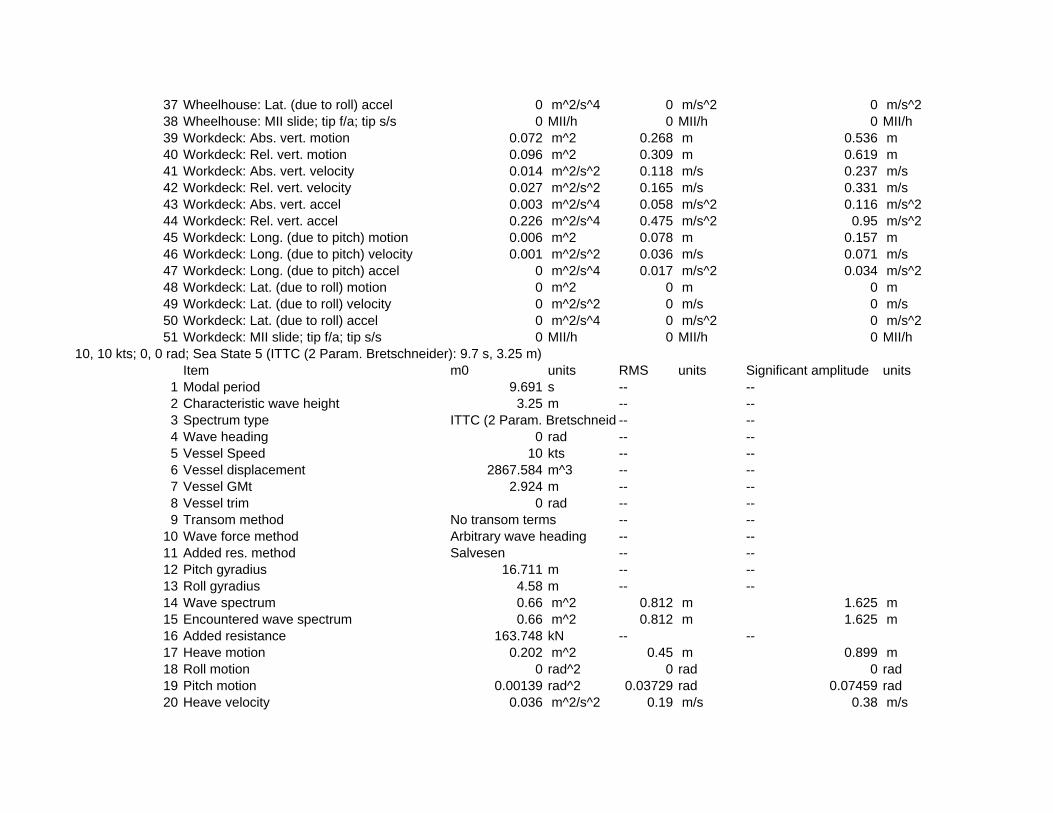
37 Wheelhouse: Lat. (due to roll) accel 0 m^2/s^4 0 m/s^2 0 m/s^238 Wheelhouse: MII slide; tip f/a; tip s/s 0 MII/h 0 MII/h 0 MII/h39 Workdeck: Abs. vert. motion 0.072 m^2 0.268 m 0.536 m40 Workdeck: Rel. vert. motion 0.096 m^2 0.309 m 0.619 m41 Workdeck: Abs. vert. velocity 0.014 m^2/s^2 0.118 m/s 0.237 m/s42 Workdeck: Rel. vert. velocity 0.027 m^2/s^2 0.165 m/s 0.331 m/s43 Workdeck: Abs. vert. accel 0.003 m^2/s^4 0.058 m/s^2 0.116 m/s^244 Workdeck: Rel. vert. accel 0.226 m^2/s^4 0.475 m/s^2 0.95 m/s^245 Workdeck: Long. (due to pitch) motion 0.006 m^2 0.078 m 0.157 m46 Workdeck: Long. (due to pitch) velocity 0.001 m^2/s^2 0.036 m/s 0.071 m/s47 Workdeck: Long. (due to pitch) accel 0 m^2/s^4 0.017 m/s^2 0.034 m/s^248 Workdeck: Lat. (due to roll) motion 0 m^2 0 m 0 m49 Workdeck: Lat. (due to roll) velocity 0 m^2/s^2 0 m/s 0 m/s50 Workdeck: Lat. (due to roll) accel 0 m^2/s^4 0 m/s^2 0 m/s^251 Workdeck: MII slide; tip f/a; tip s/s 0 MII/h 0 MII/h 0 MII/h
10, 10 kts; 0, 0 rad; Sea State 5 (ITTC (2 Param. Bretschneider): 9.7 s, 3.25 m)Item m0 units RMS units Significant amplitude units
1 Modal period 9.691 s -- --2 Characteristic wave height 3.25 m -- --3 Spectrum type ITTC (2 Param. Bretschneid -- --4 Wave heading 0 rad -- --5 Vessel Speed 10 kts -- --6 Vessel displacement 2867.584 m^3 -- --7 Vessel GMt 2.924 m -- --8 Vessel trim 0 rad -- --9 Transom method No transom terms -- --
10 Wave force method Arbitrary wave heading -- --11 Added res. method Salvesen -- --12 Pitch gyradius 16.711 m -- --13 Roll gyradius 4.58 m -- --14 Wave spectrum 0.66 m^2 0.812 m 1.625 m15 Encountered wave spectrum 0.66 m^2 0.812 m 1.625 m16 Added resistance 163.748 kN -- --17 Heave motion 0.202 m^2 0.45 m 0.899 m18 Roll motion 0 rad^2 0 rad 0 rad19 Pitch motion 0.00139 rad^2 0.03729 rad 0.07459 rad20 Heave velocity 0.036 m^2/s^2 0.19 m/s 0.38 m/s

21 Roll velocity 0 (rad/s)^2 0 rad/s 0 rad/s22 Pitch velocity 0.00028 (rad/s)^2 0.01673 rad/s 0.03347 rad/s23 Heave acceleration 0.007 m^2/s^4 0.085 m/s^2 0.17 m/s^224 Roll acceleration 0 (rad/s/s)^2 0 rad/s/s 0 rad/s/s)25 Pitch acceleration 0.00006 (rad/s/s)^2 0.00782 rad/s/s 0.01565 rad/s/s)26 Wheelhouse: Abs. vert. motion 0.365 m^2 0.604 m 1.209 m27 Wheelhouse: Rel. vert. motion 0.185 m^2 0.43 m 0.86 m28 Wheelhouse: Abs. vert. velocity 0.07 m^2/s^2 0.264 m/s 0.528 m/s29 Wheelhouse: Rel. vert. velocity 0.045 m^2/s^2 0.211 m/s 0.423 m/s30 Wheelhouse: Abs. vert. accel 0.014 m^2/s^4 0.119 m/s^2 0.238 m/s^231 Wheelhouse: Rel. vert. accel 0.237 m^2/s^4 0.487 m/s^2 0.974 m/s^232 Wheelhouse: Long. (due to pitch) motion 0.156 m^2 0.395 m 0.789 m33 Wheelhouse: Long. (due to pitch) velocity 0.031 m^2/s^2 0.176 m/s 0.353 m/s34 Wheelhouse: Long. (due to pitch) accel 0.007 m^2/s^4 0.082 m/s^2 0.165 m/s^235 Wheelhouse: Lat. (due to roll) motion 0 m^2 0 m 0 m36 Wheelhouse: Lat. (due to roll) velocity 0 m^2/s^2 0 m/s 0 m/s37 Wheelhouse: Lat. (due to roll) accel 0 m^2/s^4 0 m/s^2 0 m/s^238 Wheelhouse: MII slide; tip f/a; tip s/s 0 MII/h 0 MII/h 0 MII/h39 Workdeck: Abs. vert. motion 0.279 m^2 0.529 m 1.057 m40 Workdeck: Rel. vert. motion 0.215 m^2 0.463 m 0.927 m41 Workdeck: Abs. vert. velocity 0.051 m^2/s^2 0.226 m/s 0.451 m/s42 Workdeck: Rel. vert. velocity 0.06 m^2/s^2 0.244 m/s 0.489 m/s43 Workdeck: Abs. vert. accel 0.011 m^2/s^4 0.103 m/s^2 0.207 m/s^244 Workdeck: Rel. vert. accel 0.461 m^2/s^4 0.679 m/s^2 1.358 m/s^245 Workdeck: Long. (due to pitch) motion 0.019 m^2 0.138 m 0.276 m46 Workdeck: Long. (due to pitch) velocity 0.004 m^2/s^2 0.062 m/s 0.123 m/s47 Workdeck: Long. (due to pitch) accel 0.001 m^2/s^4 0.029 m/s^2 0.058 m/s^248 Workdeck: Lat. (due to roll) motion 0 m^2 0 m 0 m49 Workdeck: Lat. (due to roll) velocity 0 m^2/s^2 0 m/s 0 m/s50 Workdeck: Lat. (due to roll) accel 0 m^2/s^4 0 m/s^2 0 m/s^251 Workdeck: MII slide; tip f/a; tip s/s 0 MII/h 0 MII/h 0 MII/h
10, 10 kts; 0, 0 rad; Sea State 6 (ITTC (2 Param. Bretschneider): 12.4 s, 5 m)Item m0 units RMS units Significant amplitude units
1 Modal period 12.388 s -- --2 Characteristic wave height 5 m -- --3 Spectrum type ITTC (2 Param. Bretschneid -- --4 Wave heading 0 rad -- --

5 Vessel Speed 10 kts -- --6 Vessel displacement 2867.584 m^3 -- --7 Vessel GMt 2.924 m -- --8 Vessel trim 0 rad -- --9 Transom method No transom terms -- --
10 Wave force method Arbitrary wave heading -- --11 Added res. method Salvesen -- --12 Pitch gyradius 16.711 m -- --13 Roll gyradius 4.58 m -- --14 Wave spectrum 1.563 m^2 1.25 m 2.5 m15 Encountered wave spectrum 1.562 m^2 1.25 m 2.5 m16 Added resistance 300.968 kN -- --17 Heave motion 0.827 m^2 0.909 m 1.819 m18 Roll motion 0 rad^2 0 rad 0 rad19 Pitch motion 0.00265 rad^2 0.0515 rad 0.103 rad20 Heave velocity 0.121 m^2/s^2 0.348 m/s 0.696 m/s21 Roll velocity 0 (rad/s)^2 0 rad/s 0 rad/s22 Pitch velocity 0.00048 (rad/s)^2 0.02202 rad/s 0.04404 rad/s23 Heave acceleration 0.019 m^2/s^4 0.139 m/s^2 0.277 m/s^224 Roll acceleration 0 (rad/s/s)^2 0 rad/s/s 0 rad/s/s)25 Pitch acceleration 0.0001 (rad/s/s)^2 0.00976 rad/s/s 0.01952 rad/s/s)26 Wheelhouse: Abs. vert. motion 1.067 m^2 1.033 m 2.066 m27 Wheelhouse: Rel. vert. motion 0.25 m^2 0.5 m 1 m28 Wheelhouse: Abs. vert. velocity 0.169 m^2/s^2 0.411 m/s 0.823 m/s29 Wheelhouse: Rel. vert. velocity 0.055 m^2/s^2 0.234 m/s 0.467 m/s30 Wheelhouse: Abs. vert. accel 0.029 m^2/s^4 0.17 m/s^2 0.34 m/s^231 Wheelhouse: Rel. vert. accel 0.207 m^2/s^4 0.455 m/s^2 0.909 m/s^232 Wheelhouse: Long. (due to pitch) motion 0.309 m^2 0.556 m 1.111 m33 Wheelhouse: Long. (due to pitch) velocity 0.056 m^2/s^2 0.236 m/s 0.472 m/s34 Wheelhouse: Long. (due to pitch) accel 0.011 m^2/s^4 0.104 m/s^2 0.208 m/s^235 Wheelhouse: Lat. (due to roll) motion 0 m^2 0 m 0 m36 Wheelhouse: Lat. (due to roll) velocity 0 m^2/s^2 0 m/s 0 m/s37 Wheelhouse: Lat. (due to roll) accel 0 m^2/s^4 0 m/s^2 0 m/s^238 Wheelhouse: MII slide; tip f/a; tip s/s 0 MII/h 0 MII/h 0 MII/h39 Workdeck: Abs. vert. motion 1.022 m^2 1.011 m 2.022 m40 Workdeck: Rel. vert. motion 0.224 m^2 0.474 m 0.947 m41 Workdeck: Abs. vert. velocity 0.154 m^2/s^2 0.392 m/s 0.785 m/s

42 Workdeck: Rel. vert. velocity 0.06 m^2/s^2 0.244 m/s 0.489 m/s43 Workdeck: Abs. vert. accel 0.025 m^2/s^4 0.16 m/s^2 0.319 m/s^244 Workdeck: Rel. vert. accel 0.403 m^2/s^4 0.635 m/s^2 1.27 m/s^245 Workdeck: Long. (due to pitch) motion 0.038 m^2 0.194 m 0.389 m46 Workdeck: Long. (due to pitch) velocity 0.007 m^2/s^2 0.083 m/s 0.165 m/s47 Workdeck: Long. (due to pitch) accel 0.001 m^2/s^4 0.036 m/s^2 0.073 m/s^248 Workdeck: Lat. (due to roll) motion 0 m^2 0 m 0 m49 Workdeck: Lat. (due to roll) velocity 0 m^2/s^2 0 m/s 0 m/s50 Workdeck: Lat. (due to roll) accel 0 m^2/s^4 0 m/s^2 0 m/s^251 Workdeck: MII slide; tip f/a; tip s/s 0 MII/h 0 MII/h 0 MII/h
10, 10 kts; 30, 0.52 rad; Sea State 4 (ITTC (2 Param. Bretschneider): 8.8 s, 1.88 m)Item m0 units RMS units Significant amplitude units
1 Modal period 8.792 s -- --2 Characteristic wave height 1.88 m -- --3 Spectrum type ITTC (2 Param. Bretschneid -- --4 Wave heading 0.52 rad -- --5 Vessel Speed 10 kts -- --6 Vessel displacement 2867.584 m^3 -- --7 Vessel GMt 2.924 m -- --8 Vessel trim 0 rad -- --9 Transom method No transom terms -- --
10 Wave force method Arbitrary wave heading -- --11 Added res. method Salvesen -- --12 Pitch gyradius 16.711 m -- --13 Roll gyradius 4.58 m -- --14 Wave spectrum 0.221 m^2 0.47 m 0.94 m15 Encountered wave spectrum 0.221 m^2 0.47 m 0.94 m16 Added resistance 59.918 kN -- --17 Heave motion 0.061 m^2 0.247 m 0.493 m18 Roll motion 0.00165 rad^2 0.04057 rad 0.08114 rad19 Pitch motion 0.00047 rad^2 0.02164 rad 0.04329 rad20 Heave velocity 0.014 m^2/s^2 0.117 m/s 0.233 m/s21 Roll velocity 0.0007 (rad/s)^2 0.02642 rad/s 0.05285 rad/s22 Pitch velocity 0.00012 (rad/s)^2 0.0109 rad/s 0.02179 rad/s23 Heave acceleration 0.003 m^2/s^4 0.058 m/s^2 0.115 m/s^224 Roll acceleration 0.001 (rad/s/s)^2 0.03157 rad/s/s 0.06314 rad/s/s)25 Pitch acceleration 0.00003 (rad/s/s)^2 0.00567 rad/s/s 0.01133 rad/s/s)

26 Wheelhouse: Abs. vert. motion 0.107 m^2 0.327 m 0.654 m27 Wheelhouse: Rel. vert. motion 0.071 m^2 0.267 m 0.533 m28 Wheelhouse: Abs. vert. velocity 0.026 m^2/s^2 0.161 m/s 0.322 m/s29 Wheelhouse: Rel. vert. velocity 0.02 m^2/s^2 0.142 m/s 0.284 m/s30 Wheelhouse: Abs. vert. accel 0.007 m^2/s^4 0.081 m/s^2 0.162 m/s^231 Wheelhouse: Rel. vert. accel 0.047 m^2/s^4 0.218 m/s^2 0.436 m/s^232 Wheelhouse: Long. (due to pitch) motion 0.052 m^2 0.228 m 0.457 m33 Wheelhouse: Long. (due to pitch) velocity 0.013 m^2/s^2 0.114 m/s 0.229 m/s34 Wheelhouse: Long. (due to pitch) accel 0.004 m^2/s^4 0.059 m/s^2 0.119 m/s^235 Wheelhouse: Lat. (due to roll) motion 0.2 m^2 0.447 m 0.894 m36 Wheelhouse: Lat. (due to roll) velocity 0.083 m^2/s^2 0.289 m/s 0.578 m/s37 Wheelhouse: Lat. (due to roll) accel 0.117 m^2/s^4 0.342 m/s^2 0.685 m/s^238 Wheelhouse: MII slide; tip f/a; tip s/s 0 MII/h 0.001 MII/h 0 MII/h39 Workdeck: Abs. vert. motion 0.117 m^2 0.342 m 0.684 m40 Workdeck: Rel. vert. motion 0.055 m^2 0.235 m 0.47 m41 Workdeck: Abs. vert. velocity 0.03 m^2/s^2 0.172 m/s 0.345 m/s42 Workdeck: Rel. vert. velocity 0.022 m^2/s^2 0.147 m/s 0.293 m/s43 Workdeck: Abs. vert. accel 0.014 m^2/s^4 0.119 m/s^2 0.239 m/s^244 Workdeck: Rel. vert. accel 0.105 m^2/s^4 0.324 m/s^2 0.647 m/s^245 Workdeck: Long. (due to pitch) motion 0.006 m^2 0.08 m 0.16 m46 Workdeck: Long. (due to pitch) velocity 0.002 m^2/s^2 0.04 m/s 0.08 m/s47 Workdeck: Long. (due to pitch) accel 0 m^2/s^4 0.021 m/s^2 0.042 m/s^248 Workdeck: Lat. (due to roll) motion 0.024 m^2 0.156 m 0.313 m49 Workdeck: Lat. (due to roll) velocity 0.01 m^2/s^2 0.101 m/s 0.202 m/s50 Workdeck: Lat. (due to roll) accel 0.014 m^2/s^4 0.12 m/s^2 0.239 m/s^251 Workdeck: MII slide; tip f/a; tip s/s 0 MII/h 0 MII/h 0 MII/h
10, 10 kts; 30, 0.52 rad; Sea State 5 (ITTC (2 Param. Bretschneider): 9.7 s, 3.25 m)Item m0 units RMS units Significant amplitude units
1 Modal period 9.691 s -- --2 Characteristic wave height 3.25 m -- --3 Spectrum type ITTC (2 Param. Bretschneid -- --4 Wave heading 0.52 rad -- --5 Vessel Speed 10 kts -- --6 Vessel displacement 2867.584 m^3 -- --7 Vessel GMt 2.924 m -- --8 Vessel trim 0 rad -- --9 Transom method No transom terms -- --

10 Wave force method Arbitrary wave heading -- --11 Added res. method Salvesen -- --12 Pitch gyradius 16.711 m -- --13 Roll gyradius 4.58 m -- --14 Wave spectrum 0.66 m^2 0.812 m 1.625 m15 Encountered wave spectrum 0.66 m^2 0.813 m 1.625 m16 Added resistance 163.612 kN -- --17 Heave motion 0.239 m^2 0.489 m 0.978 m18 Roll motion 0.00357 rad^2 0.05971 rad 0.11942 rad19 Pitch motion 0.00138 rad^2 0.03718 rad 0.07436 rad20 Heave velocity 0.05 m^2/s^2 0.223 m/s 0.445 m/s21 Roll velocity 0.00147 (rad/s)^2 0.03836 rad/s 0.07673 rad/s22 Pitch velocity 0.00034 (rad/s)^2 0.01834 rad/s 0.03667 rad/s23 Heave acceleration 0.011 m^2/s^4 0.105 m/s^2 0.21 m/s^224 Roll acceleration 0.00204 (rad/s/s)^2 0.04511 rad/s/s 0.09023 rad/s/s)25 Pitch acceleration 0.00009 (rad/s/s)^2 0.00932 rad/s/s 0.01864 rad/s/s)26 Wheelhouse: Abs. vert. motion 0.356 m^2 0.596 m 1.193 m27 Wheelhouse: Rel. vert. motion 0.176 m^2 0.42 m 0.839 m28 Wheelhouse: Abs. vert. velocity 0.081 m^2/s^2 0.284 m/s 0.568 m/s29 Wheelhouse: Rel. vert. velocity 0.048 m^2/s^2 0.22 m/s 0.44 m/s30 Wheelhouse: Abs. vert. accel 0.019 m^2/s^4 0.138 m/s^2 0.277 m/s^231 Wheelhouse: Rel. vert. accel 0.099 m^2/s^4 0.315 m/s^2 0.63 m/s^232 Wheelhouse: Long. (due to pitch) motion 0.157 m^2 0.396 m 0.792 m33 Wheelhouse: Long. (due to pitch) velocity 0.038 m^2/s^2 0.194 m/s 0.388 m/s34 Wheelhouse: Long. (due to pitch) accel 0.01 m^2/s^4 0.098 m/s^2 0.196 m/s^235 Wheelhouse: Lat. (due to roll) motion 0.434 m^2 0.659 m 1.318 m36 Wheelhouse: Lat. (due to roll) velocity 0.176 m^2/s^2 0.42 m/s 0.84 m/s37 Wheelhouse: Lat. (due to roll) accel 0.239 m^2/s^4 0.489 m/s^2 0.979 m/s^238 Wheelhouse: MII slide; tip f/a; tip s/s 0 MII/h 0.283 MII/h 0.001 MII/h39 Workdeck: Abs. vert. motion 0.408 m^2 0.639 m 1.277 m40 Workdeck: Rel. vert. motion 0.125 m^2 0.354 m 0.708 m41 Workdeck: Abs. vert. velocity 0.094 m^2/s^2 0.306 m/s 0.612 m/s42 Workdeck: Rel. vert. velocity 0.047 m^2/s^2 0.217 m/s 0.434 m/s43 Workdeck: Abs. vert. accel 0.036 m^2/s^4 0.189 m/s^2 0.378 m/s^244 Workdeck: Rel. vert. accel 0.214 m^2/s^4 0.463 m/s^2 0.925 m/s^245 Workdeck: Long. (due to pitch) motion 0.019 m^2 0.138 m 0.277 m46 Workdeck: Long. (due to pitch) velocity 0.005 m^2/s^2 0.068 m/s 0.136 m/s

47 Workdeck: Long. (due to pitch) accel 0.001 m^2/s^4 0.034 m/s^2 0.069 m/s^248 Workdeck: Lat. (due to roll) motion 0.053 m^2 0.23 m 0.461 m49 Workdeck: Lat. (due to roll) velocity 0.022 m^2/s^2 0.147 m/s 0.294 m/s50 Workdeck: Lat. (due to roll) accel 0.029 m^2/s^4 0.171 m/s^2 0.342 m/s^251 Workdeck: MII slide; tip f/a; tip s/s 0 MII/h 0.189 MII/h 0.001 MII/h
10, 10 kts; 30, 0.52 rad; Sea State 6 (ITTC (2 Param. Bretschneider): 12.4 s, 5 m)Item m0 units RMS units Significant amplitude units
1 Modal period 12.388 s -- --2 Characteristic wave height 5 m -- --3 Spectrum type ITTC (2 Param. Bretschneid -- --4 Wave heading 0.52 rad -- --5 Vessel Speed 10 kts -- --6 Vessel displacement 2867.584 m^3 -- --7 Vessel GMt 2.924 m -- --8 Vessel trim 0 rad -- --9 Transom method No transom terms -- --
10 Wave force method Arbitrary wave heading -- --11 Added res. method Salvesen -- --12 Pitch gyradius 16.711 m -- --13 Roll gyradius 4.58 m -- --14 Wave spectrum 1.563 m^2 1.25 m 2.5 m15 Encountered wave spectrum 1.562 m^2 1.25 m 2.5 m16 Added resistance 303.586 kN -- --17 Heave motion 0.91 m^2 0.954 m 1.908 m18 Roll motion 0.00365 rad^2 0.06044 rad 0.12088 rad19 Pitch motion 0.0025 rad^2 0.04996 rad 0.09992 rad20 Heave velocity 0.152 m^2/s^2 0.389 m/s 0.779 m/s21 Roll velocity 0.00141 (rad/s)^2 0.03759 rad/s 0.07518 rad/s22 Pitch velocity 0.00054 (rad/s)^2 0.02333 rad/s 0.04666 rad/s23 Heave acceleration 0.027 m^2/s^4 0.165 m/s^2 0.331 m/s^224 Roll acceleration 0.00183 (rad/s/s)^2 0.04275 rad/s/s 0.0855 rad/s/s)25 Pitch acceleration 0.00013 (rad/s/s)^2 0.01128 rad/s/s 0.02256 rad/s/s)26 Wheelhouse: Abs. vert. motion 1.032 m^2 1.016 m 2.032 m27 Wheelhouse: Rel. vert. motion 0.234 m^2 0.483 m 0.967 m28 Wheelhouse: Abs. vert. velocity 0.186 m^2/s^2 0.432 m/s 0.864 m/s29 Wheelhouse: Rel. vert. velocity 0.059 m^2/s^2 0.243 m/s 0.486 m/s30 Wheelhouse: Abs. vert. accel 0.037 m^2/s^4 0.192 m/s^2 0.384 m/s^2
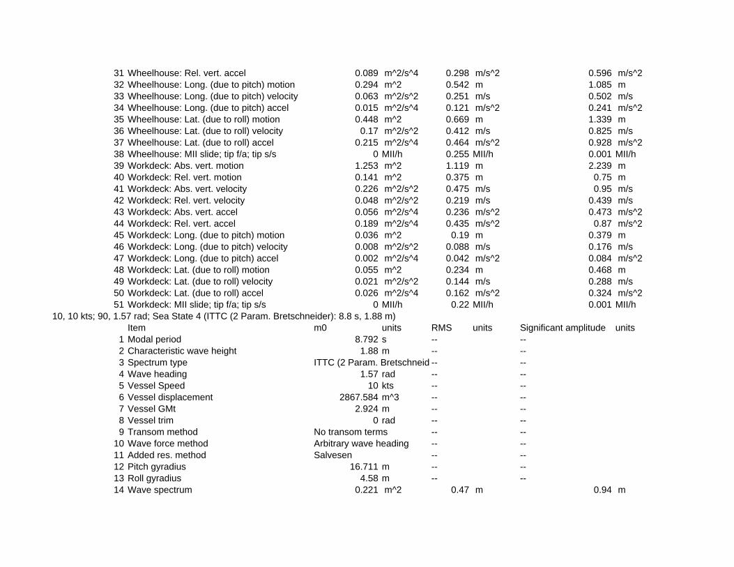
31 Wheelhouse: Rel. vert. accel 0.089 m^2/s^4 0.298 m/s^2 0.596 m/s^232 Wheelhouse: Long. (due to pitch) motion 0.294 m^2 0.542 m 1.085 m33 Wheelhouse: Long. (due to pitch) velocity 0.063 m^2/s^2 0.251 m/s 0.502 m/s34 Wheelhouse: Long. (due to pitch) accel 0.015 m^2/s^4 0.121 m/s^2 0.241 m/s^235 Wheelhouse: Lat. (due to roll) motion 0.448 m^2 0.669 m 1.339 m36 Wheelhouse: Lat. (due to roll) velocity 0.17 m^2/s^2 0.412 m/s 0.825 m/s37 Wheelhouse: Lat. (due to roll) accel 0.215 m^2/s^4 0.464 m/s^2 0.928 m/s^238 Wheelhouse: MII slide; tip f/a; tip s/s 0 MII/h 0.255 MII/h 0.001 MII/h39 Workdeck: Abs. vert. motion 1.253 m^2 1.119 m 2.239 m40 Workdeck: Rel. vert. motion 0.141 m^2 0.375 m 0.75 m41 Workdeck: Abs. vert. velocity 0.226 m^2/s^2 0.475 m/s 0.95 m/s42 Workdeck: Rel. vert. velocity 0.048 m^2/s^2 0.219 m/s 0.439 m/s43 Workdeck: Abs. vert. accel 0.056 m^2/s^4 0.236 m/s^2 0.473 m/s^244 Workdeck: Rel. vert. accel 0.189 m^2/s^4 0.435 m/s^2 0.87 m/s^245 Workdeck: Long. (due to pitch) motion 0.036 m^2 0.19 m 0.379 m46 Workdeck: Long. (due to pitch) velocity 0.008 m^2/s^2 0.088 m/s 0.176 m/s47 Workdeck: Long. (due to pitch) accel 0.002 m^2/s^4 0.042 m/s^2 0.084 m/s^248 Workdeck: Lat. (due to roll) motion 0.055 m^2 0.234 m 0.468 m49 Workdeck: Lat. (due to roll) velocity 0.021 m^2/s^2 0.144 m/s 0.288 m/s50 Workdeck: Lat. (due to roll) accel 0.026 m^2/s^4 0.162 m/s^2 0.324 m/s^251 Workdeck: MII slide; tip f/a; tip s/s 0 MII/h 0.22 MII/h 0.001 MII/h
10, 10 kts; 90, 1.57 rad; Sea State 4 (ITTC (2 Param. Bretschneider): 8.8 s, 1.88 m)Item m0 units RMS units Significant amplitude units
1 Modal period 8.792 s -- --2 Characteristic wave height 1.88 m -- --3 Spectrum type ITTC (2 Param. Bretschneid -- --4 Wave heading 1.57 rad -- --5 Vessel Speed 10 kts -- --6 Vessel displacement 2867.584 m^3 -- --7 Vessel GMt 2.924 m -- --8 Vessel trim 0 rad -- --9 Transom method No transom terms -- --
10 Wave force method Arbitrary wave heading -- --11 Added res. method Salvesen -- --12 Pitch gyradius 16.711 m -- --13 Roll gyradius 4.58 m -- --14 Wave spectrum 0.221 m^2 0.47 m 0.94 m
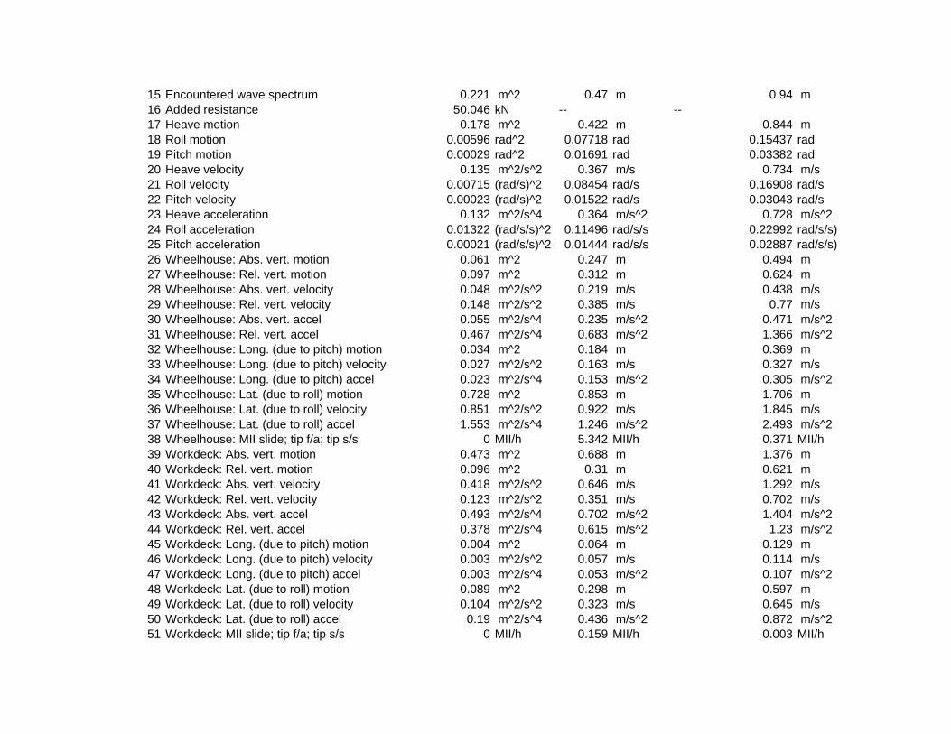
15 Encountered wave spectrum 0.221 m^2 0.47 m 0.94 m16 Added resistance 50.046 kN -- --17 Heave motion 0.178 m^2 0.422 m 0.844 m18 Roll motion 0.00596 rad^2 0.07718 rad 0.15437 rad19 Pitch motion 0.00029 rad^2 0.01691 rad 0.03382 rad20 Heave velocity 0.135 m^2/s^2 0.367 m/s 0.734 m/s21 Roll velocity 0.00715 (rad/s)^2 0.08454 rad/s 0.16908 rad/s22 Pitch velocity 0.00023 (rad/s)^2 0.01522 rad/s 0.03043 rad/s23 Heave acceleration 0.132 m^2/s^4 0.364 m/s^2 0.728 m/s^224 Roll acceleration 0.01322 (rad/s/s)^2 0.11496 rad/s/s 0.22992 rad/s/s)25 Pitch acceleration 0.00021 (rad/s/s)^2 0.01444 rad/s/s 0.02887 rad/s/s)26 Wheelhouse: Abs. vert. motion 0.061 m^2 0.247 m 0.494 m27 Wheelhouse: Rel. vert. motion 0.097 m^2 0.312 m 0.624 m28 Wheelhouse: Abs. vert. velocity 0.048 m^2/s^2 0.219 m/s 0.438 m/s29 Wheelhouse: Rel. vert. velocity 0.148 m^2/s^2 0.385 m/s 0.77 m/s30 Wheelhouse: Abs. vert. accel 0.055 m^2/s^4 0.235 m/s^2 0.471 m/s^231 Wheelhouse: Rel. vert. accel 0.467 m^2/s^4 0.683 m/s^2 1.366 m/s^232 Wheelhouse: Long. (due to pitch) motion 0.034 m^2 0.184 m 0.369 m33 Wheelhouse: Long. (due to pitch) velocity 0.027 m^2/s^2 0.163 m/s 0.327 m/s34 Wheelhouse: Long. (due to pitch) accel 0.023 m^2/s^4 0.153 m/s^2 0.305 m/s^235 Wheelhouse: Lat. (due to roll) motion 0.728 m^2 0.853 m 1.706 m36 Wheelhouse: Lat. (due to roll) velocity 0.851 m^2/s^2 0.922 m/s 1.845 m/s37 Wheelhouse: Lat. (due to roll) accel 1.553 m^2/s^4 1.246 m/s^2 2.493 m/s^238 Wheelhouse: MII slide; tip f/a; tip s/s 0 MII/h 5.342 MII/h 0.371 MII/h39 Workdeck: Abs. vert. motion 0.473 m^2 0.688 m 1.376 m40 Workdeck: Rel. vert. motion 0.096 m^2 0.31 m 0.621 m41 Workdeck: Abs. vert. velocity 0.418 m^2/s^2 0.646 m/s 1.292 m/s42 Workdeck: Rel. vert. velocity 0.123 m^2/s^2 0.351 m/s 0.702 m/s43 Workdeck: Abs. vert. accel 0.493 m^2/s^4 0.702 m/s^2 1.404 m/s^244 Workdeck: Rel. vert. accel 0.378 m^2/s^4 0.615 m/s^2 1.23 m/s^245 Workdeck: Long. (due to pitch) motion 0.004 m^2 0.064 m 0.129 m46 Workdeck: Long. (due to pitch) velocity 0.003 m^2/s^2 0.057 m/s 0.114 m/s47 Workdeck: Long. (due to pitch) accel 0.003 m^2/s^4 0.053 m/s^2 0.107 m/s^248 Workdeck: Lat. (due to roll) motion 0.089 m^2 0.298 m 0.597 m49 Workdeck: Lat. (due to roll) velocity 0.104 m^2/s^2 0.323 m/s 0.645 m/s50 Workdeck: Lat. (due to roll) accel 0.19 m^2/s^4 0.436 m/s^2 0.872 m/s^251 Workdeck: MII slide; tip f/a; tip s/s 0 MII/h 0.159 MII/h 0.003 MII/h

10, 10 kts; 90, 1.57 rad; Sea State 5 (ITTC (2 Param. Bretschneider): 9.7 s, 3.25 m)Item m0 units RMS units Significant amplitude units
1 Modal period 9.691 s -- --2 Characteristic wave height 3.25 m -- --3 Spectrum type ITTC (2 Param. Bretschneid -- --4 Wave heading 1.57 rad -- --5 Vessel Speed 10 kts -- --6 Vessel displacement 2867.584 m^3 -- --7 Vessel GMt 2.924 m -- --8 Vessel trim 0 rad -- --9 Transom method No transom terms -- --
10 Wave force method Arbitrary wave heading -- --11 Added res. method Salvesen -- --12 Pitch gyradius 16.711 m -- --13 Roll gyradius 4.58 m -- --14 Wave spectrum 0.66 m^2 0.812 m 1.625 m15 Encountered wave spectrum 0.66 m^2 0.812 m 1.625 m16 Added resistance 143.89 kN -- --17 Heave motion 0.557 m^2 0.746 m 1.493 m18 Roll motion 0.01403 rad^2 0.11847 rad 0.23693 rad19 Pitch motion 0.00074 rad^2 0.02714 rad 0.05427 rad20 Heave velocity 0.359 m^2/s^2 0.599 m/s 1.199 m/s21 Roll velocity 0.01595 (rad/s)^2 0.12631 rad/s 0.25262 rad/s22 Pitch velocity 0.00057 (rad/s)^2 0.0238 rad/s 0.04759 rad/s23 Heave acceleration 0.315 m^2/s^4 0.561 m/s^2 1.122 m/s^224 Roll acceleration 0.02812 (rad/s/s)^2 0.1677 rad/s/s 0.3354 rad/s/s)25 Pitch acceleration 0.00049 (rad/s/s)^2 0.02214 rad/s/s 0.04428 rad/s/s)26 Wheelhouse: Abs. vert. motion 0.217 m^2 0.466 m 0.933 m27 Wheelhouse: Rel. vert. motion 0.233 m^2 0.483 m 0.966 m28 Wheelhouse: Abs. vert. velocity 0.133 m^2/s^2 0.364 m/s 0.729 m/s29 Wheelhouse: Rel. vert. velocity 0.325 m^2/s^2 0.57 m/s 1.14 m/s30 Wheelhouse: Abs. vert. accel 0.129 m^2/s^4 0.359 m/s^2 0.719 m/s^231 Wheelhouse: Rel. vert. accel 0.968 m^2/s^4 0.984 m/s^2 1.967 m/s^232 Wheelhouse: Long. (due to pitch) motion 0.089 m^2 0.299 m 0.597 m33 Wheelhouse: Long. (due to pitch) velocity 0.066 m^2/s^2 0.257 m/s 0.514 m/s34 Wheelhouse: Long. (due to pitch) accel 0.055 m^2/s^4 0.235 m/s^2 0.471 m/s^235 Wheelhouse: Lat. (due to roll) motion 1.732 m^2 1.316 m 2.632 m

36 Wheelhouse: Lat. (due to roll) velocity 1.911 m^2/s^2 1.382 m/s 2.765 m/s37 Wheelhouse: Lat. (due to roll) accel 3.313 m^2/s^4 1.82 m/s^2 3.64 m/s^238 Wheelhouse: MII slide; tip f/a; tip s/s 0 MII/h 17.628 MII/h 4.833 MII/h39 Workdeck: Abs. vert. motion 1.312 m^2 1.146 m 2.291 m40 Workdeck: Rel. vert. motion 0.239 m^2 0.489 m 0.978 m41 Workdeck: Abs. vert. velocity 1.027 m^2/s^2 1.013 m/s 2.027 m/s42 Workdeck: Rel. vert. velocity 0.277 m^2/s^2 0.526 m/s 1.053 m/s43 Workdeck: Abs. vert. accel 1.115 m^2/s^4 1.056 m/s^2 2.112 m/s^244 Workdeck: Rel. vert. accel 0.789 m^2/s^4 0.888 m/s^2 1.776 m/s^245 Workdeck: Long. (due to pitch) motion 0.011 m^2 0.104 m 0.209 m46 Workdeck: Long. (due to pitch) velocity 0.008 m^2/s^2 0.09 m/s 0.18 m/s47 Workdeck: Long. (due to pitch) accel 0.007 m^2/s^4 0.082 m/s^2 0.165 m/s^248 Workdeck: Lat. (due to roll) motion 0.212 m^2 0.46 m 0.921 m49 Workdeck: Lat. (due to roll) velocity 0.234 m^2/s^2 0.483 m/s 0.967 m/s50 Workdeck: Lat. (due to roll) accel 0.405 m^2/s^4 0.637 m/s^2 1.273 m/s^251 Workdeck: MII slide; tip f/a; tip s/s 0 MII/h 2.472 MII/h 0.39 MII/h
10, 10 kts; 90, 1.57 rad; Sea State 6 (ITTC (2 Param. Bretschneider): 12.4 s, 5 m)Item m0 units RMS units Significant amplitude units
1 Modal period 12.388 s -- --2 Characteristic wave height 5 m -- --3 Spectrum type ITTC (2 Param. Bretschneid -- --4 Wave heading 1.57 rad -- --5 Vessel Speed 10 kts -- --6 Vessel displacement 2867.584 m^3 -- --7 Vessel GMt 2.924 m -- --8 Vessel trim 0 rad -- --9 Transom method No transom terms -- --
10 Wave force method Arbitrary wave heading -- --11 Added res. method Salvesen -- --12 Pitch gyradius 16.711 m -- --13 Roll gyradius 4.58 m -- --14 Wave spectrum 1.563 m^2 1.25 m 2.5 m15 Encountered wave spectrum 1.563 m^2 1.25 m 2.5 m16 Added resistance 294.033 kN -- --17 Heave motion 1.437 m^2 1.199 m 2.398 m18 Roll motion 0.01621 rad^2 0.12732 rad 0.25464 rad19 Pitch motion 0.00097 rad^2 0.03122 rad 0.06244 rad

20 Heave velocity 0.608 m^2/s^2 0.78 m/s 1.56 m/s21 Roll velocity 0.01652 (rad/s)^2 0.12851 rad/s 0.25703 rad/s22 Pitch velocity 0.00068 (rad/s)^2 0.02598 rad/s 0.05196 rad/s23 Heave acceleration 0.391 m^2/s^4 0.625 m/s^2 1.25 m/s^224 Roll acceleration 0.02686 (rad/s/s)^2 0.16388 rad/s/s 0.32775 rad/s/s)25 Pitch acceleration 0.00054 (rad/s/s)^2 0.02332 rad/s/s 0.04664 rad/s/s)26 Wheelhouse: Abs. vert. motion 0.812 m^2 0.901 m 1.802 m27 Wheelhouse: Rel. vert. motion 0.282 m^2 0.531 m 1.063 m28 Wheelhouse: Abs. vert. velocity 0.283 m^2/s^2 0.532 m/s 1.063 m/s29 Wheelhouse: Rel. vert. velocity 0.33 m^2/s^2 0.575 m/s 1.15 m/s30 Wheelhouse: Abs. vert. accel 0.168 m^2/s^4 0.409 m/s^2 0.819 m/s^231 Wheelhouse: Rel. vert. accel 0.89 m^2/s^4 0.943 m/s^2 1.886 m/s^232 Wheelhouse: Long. (due to pitch) motion 0.123 m^2 0.351 m 0.702 m33 Wheelhouse: Long. (due to pitch) velocity 0.081 m^2/s^2 0.285 m/s 0.57 m/s34 Wheelhouse: Long. (due to pitch) accel 0.063 m^2/s^4 0.25 m/s^2 0.5 m/s^235 Wheelhouse: Lat. (due to roll) motion 2.039 m^2 1.428 m 2.856 m36 Wheelhouse: Lat. (due to roll) velocity 2.001 m^2/s^2 1.414 m/s 2.829 m/s37 Wheelhouse: Lat. (due to roll) accel 3.176 m^2/s^4 1.782 m/s^2 3.564 m/s^238 Wheelhouse: MII slide; tip f/a; tip s/s 0 MII/h 16.053 MII/h 4.104 MII/h39 Workdeck: Abs. vert. motion 2.505 m^2 1.583 m 3.166 m40 Workdeck: Rel. vert. motion 0.328 m^2 0.573 m 1.146 m41 Workdeck: Abs. vert. velocity 1.388 m^2/s^2 1.178 m/s 2.356 m/s42 Workdeck: Rel. vert. velocity 0.3 m^2/s^2 0.547 m/s 1.095 m/s43 Workdeck: Abs. vert. accel 1.215 m^2/s^4 1.102 m/s^2 2.204 m/s^244 Workdeck: Rel. vert. accel 0.734 m^2/s^4 0.857 m/s^2 1.714 m/s^245 Workdeck: Long. (due to pitch) motion 0.015 m^2 0.123 m 0.246 m46 Workdeck: Long. (due to pitch) velocity 0.01 m^2/s^2 0.1 m/s 0.199 m/s47 Workdeck: Long. (due to pitch) accel 0.008 m^2/s^4 0.087 m/s^2 0.175 m/s^248 Workdeck: Lat. (due to roll) motion 0.249 m^2 0.499 m 0.999 m49 Workdeck: Lat. (due to roll) velocity 0.245 m^2/s^2 0.495 m/s 0.989 m/s50 Workdeck: Lat. (due to roll) accel 0.389 m^2/s^4 0.623 m/s^2 1.247 m/s^251 Workdeck: MII slide; tip f/a; tip s/s 0 MII/h 3.388 MII/h 0.688 MII/h
10, 10 kts; 140, 2.44 rad; Sea State 4 (ITTC (2 Param. Bretschneider): 8.8 s, 1.88 m)Item m0 units RMS units Significant amplitude units
1 Modal period 8.792 s -- --2 Characteristic wave height 1.88 m -- --3 Spectrum type ITTC (2 Param. Bretschneid -- --

4 Wave heading 2.44 rad -- --5 Vessel Speed 10 kts -- --6 Vessel displacement 2867.584 m^3 -- --7 Vessel GMt 2.924 m -- --8 Vessel trim 0 rad -- --9 Transom method No transom terms -- --
10 Wave force method Arbitrary wave heading -- --11 Added res. method Salvesen -- --12 Pitch gyradius 16.711 m -- --13 Roll gyradius 4.58 m -- --14 Wave spectrum 0.221 m^2 0.47 m 0.94 m15 Encountered wave spectrum 0.221 m^2 0.47 m 0.94 m16 Added resistance 51.238 kN -- --17 Heave motion 0.197 m^2 0.444 m 0.889 m18 Roll motion 0.0012 rad^2 0.03464 rad 0.06929 rad19 Pitch motion 0.00048 rad^2 0.02193 rad 0.04386 rad20 Heave velocity 0.203 m^2/s^2 0.45 m/s 0.9 m/s21 Roll velocity 0.00162 (rad/s)^2 0.04025 rad/s 0.08049 rad/s22 Pitch velocity 0.0006 (rad/s)^2 0.02447 rad/s 0.04894 rad/s23 Heave acceleration 0.237 m^2/s^4 0.487 m/s^2 0.974 m/s^224 Roll acceleration 0.00338 (rad/s/s)^2 0.05813 rad/s/s 0.11626 rad/s/s)25 Pitch acceleration 0.00085 (rad/s/s)^2 0.02908 rad/s/s 0.05815 rad/s/s)26 Wheelhouse: Abs. vert. motion 0.326 m^2 0.571 m 1.143 m27 Wheelhouse: Rel. vert. motion 0.201 m^2 0.449 m 0.898 m28 Wheelhouse: Abs. vert. velocity 0.354 m^2/s^2 0.595 m/s 1.191 m/s29 Wheelhouse: Rel. vert. velocity 0.479 m^2/s^2 0.692 m/s 1.384 m/s30 Wheelhouse: Abs. vert. accel 0.433 m^2/s^4 0.658 m/s^2 1.316 m/s^231 Wheelhouse: Rel. vert. accel 2.204 m^2/s^4 1.485 m/s^2 2.969 m/s^232 Wheelhouse: Long. (due to pitch) motion 0.058 m^2 0.24 m 0.48 m33 Wheelhouse: Long. (due to pitch) velocity 0.072 m^2/s^2 0.267 m/s 0.535 m/s34 Wheelhouse: Long. (due to pitch) accel 0.101 m^2/s^4 0.317 m/s^2 0.634 m/s^235 Wheelhouse: Lat. (due to roll) motion 0.144 m^2 0.379 m 0.759 m36 Wheelhouse: Lat. (due to roll) velocity 0.193 m^2/s^2 0.439 m/s 0.879 m/s37 Wheelhouse: Lat. (due to roll) accel 0.399 m^2/s^4 0.632 m/s^2 1.264 m/s^238 Wheelhouse: MII slide; tip f/a; tip s/s 0 MII/h 0.022 MII/h 0 MII/h39 Workdeck: Abs. vert. motion 0.264 m^2 0.514 m 1.028 m40 Workdeck: Rel. vert. motion 0.105 m^2 0.324 m 0.647 m

41 Workdeck: Abs. vert. velocity 0.282 m^2/s^2 0.531 m/s 1.062 m/s42 Workdeck: Rel. vert. velocity 0.323 m^2/s^2 0.569 m/s 1.137 m/s43 Workdeck: Abs. vert. accel 0.35 m^2/s^4 0.591 m/s^2 1.183 m/s^244 Workdeck: Rel. vert. accel 2.04 m^2/s^4 1.428 m/s^2 2.856 m/s^245 Workdeck: Long. (due to pitch) motion 0.007 m^2 0.084 m 0.168 m46 Workdeck: Long. (due to pitch) velocity 0.009 m^2/s^2 0.094 m/s 0.187 m/s47 Workdeck: Long. (due to pitch) accel 0.012 m^2/s^4 0.111 m/s^2 0.222 m/s^248 Workdeck: Lat. (due to roll) motion 0.018 m^2 0.133 m 0.265 m49 Workdeck: Lat. (due to roll) velocity 0.024 m^2/s^2 0.154 m/s 0.307 m/s50 Workdeck: Lat. (due to roll) accel 0.049 m^2/s^4 0.221 m/s^2 0.442 m/s^251 Workdeck: MII slide; tip f/a; tip s/s 0 MII/h 0 MII/h 0 MII/h
10, 10 kts; 140, 2.44 rad; Sea State 5 (ITTC (2 Param. Bretschneider): 9.7 s, 3.25 m)Item m0 units RMS units Significant amplitude units
1 Modal period 9.691 s -- --2 Characteristic wave height 3.25 m -- --3 Spectrum type ITTC (2 Param. Bretschneid -- --4 Wave heading 2.44 rad -- --5 Vessel Speed 10 kts -- --6 Vessel displacement 2867.584 m^3 -- --7 Vessel GMt 2.924 m -- --8 Vessel trim 0 rad -- --9 Transom method No transom terms -- --
10 Wave force method Arbitrary wave heading -- --11 Added res. method Salvesen -- --12 Pitch gyradius 16.711 m -- --13 Roll gyradius 4.58 m -- --14 Wave spectrum 0.66 m^2 0.812 m 1.625 m15 Encountered wave spectrum 0.66 m^2 0.812 m 1.625 m16 Added resistance 154.64 kN -- --17 Heave motion 0.641 m^2 0.8 m 1.601 m18 Roll motion 0.00329 rad^2 0.05735 rad 0.11469 rad19 Pitch motion 0.00133 rad^2 0.03649 rad 0.07297 rad20 Heave velocity 0.584 m^2/s^2 0.764 m/s 1.528 m/s21 Roll velocity 0.00411 (rad/s)^2 0.06407 rad/s 0.12814 rad/s22 Pitch velocity 0.00155 (rad/s)^2 0.03935 rad/s 0.0787 rad/s23 Heave acceleration 0.631 m^2/s^4 0.795 m/s^2 1.589 m/s^224 Roll acceleration 0.00777 (rad/s/s)^2 0.08816 rad/s/s 0.17631 rad/s/s)

25 Pitch acceleration 0.00208 (rad/s/s)^2 0.04563 rad/s/s 0.09126 rad/s/s)26 Wheelhouse: Abs. vert. motion 0.998 m^2 0.999 m 1.998 m27 Wheelhouse: Rel. vert. motion 0.471 m^2 0.687 m 1.373 m28 Wheelhouse: Abs. vert. velocity 0.983 m^2/s^2 0.991 m/s 1.983 m/s29 Wheelhouse: Rel. vert. velocity 1.065 m^2/s^2 1.032 m/s 2.064 m/s30 Wheelhouse: Abs. vert. accel 1.126 m^2/s^4 1.061 m/s^2 2.122 m/s^231 Wheelhouse: Rel. vert. accel 4.616 m^2/s^4 2.149 m/s^2 4.297 m/s^232 Wheelhouse: Long. (due to pitch) motion 0.16 m^2 0.4 m 0.8 m33 Wheelhouse: Long. (due to pitch) velocity 0.185 m^2/s^2 0.43 m/s 0.861 m/s34 Wheelhouse: Long. (due to pitch) accel 0.248 m^2/s^4 0.498 m/s^2 0.996 m/s^235 Wheelhouse: Lat. (due to roll) motion 0.396 m^2 0.629 m 1.258 m36 Wheelhouse: Lat. (due to roll) velocity 0.491 m^2/s^2 0.7 m/s 1.401 m/s37 Wheelhouse: Lat. (due to roll) accel 0.92 m^2/s^4 0.959 m/s^2 1.918 m/s^238 Wheelhouse: MII slide; tip f/a; tip s/s 0 MII/h 0.889 MII/h 0.049 MII/h39 Workdeck: Abs. vert. motion 0.826 m^2 0.909 m 1.818 m40 Workdeck: Rel. vert. motion 0.244 m^2 0.494 m 0.987 m41 Workdeck: Abs. vert. velocity 0.792 m^2/s^2 0.89 m/s 1.78 m/s42 Workdeck: Rel. vert. velocity 0.7 m^2/s^2 0.837 m/s 1.673 m/s43 Workdeck: Abs. vert. accel 0.91 m^2/s^4 0.954 m/s^2 1.908 m/s^244 Workdeck: Rel. vert. accel 4.202 m^2/s^4 2.05 m/s^2 4.1 m/s^245 Workdeck: Long. (due to pitch) motion 0.02 m^2 0.14 m 0.28 m46 Workdeck: Long. (due to pitch) velocity 0.023 m^2/s^2 0.151 m/s 0.301 m/s47 Workdeck: Long. (due to pitch) accel 0.03 m^2/s^4 0.174 m/s^2 0.348 m/s^248 Workdeck: Lat. (due to roll) motion 0.048 m^2 0.22 m 0.44 m49 Workdeck: Lat. (due to roll) velocity 0.06 m^2/s^2 0.245 m/s 0.49 m/s50 Workdeck: Lat. (due to roll) accel 0.113 m^2/s^4 0.335 m/s^2 0.671 m/s^251 Workdeck: MII slide; tip f/a; tip s/s 0 MII/h 0.02 MII/h 0 MII/h
10, 10 kts; 140, 2.44 rad; Sea State 6 (ITTC (2 Param. Bretschneider): 12.4 s, 5 m)Item m0 units RMS units Significant amplitude units
1 Modal period 12.388 s -- --2 Characteristic wave height 5 m -- --3 Spectrum type ITTC (2 Param. Bretschneid -- --4 Wave heading 2.44 rad -- --5 Vessel Speed 10 kts -- --6 Vessel displacement 2867.584 m^3 -- --7 Vessel GMt 2.924 m -- --8 Vessel trim 0 rad -- --

9 Transom method No transom terms -- --10 Wave force method Arbitrary wave heading -- --11 Added res. method Salvesen -- --12 Pitch gyradius 16.711 m -- --13 Roll gyradius 4.58 m -- --14 Wave spectrum 1.563 m^2 1.25 m 2.5 m15 Encountered wave spectrum 1.563 m^2 1.25 m 2.5 m16 Added resistance 327.847 kN -- --17 Heave motion 1.627 m^2 1.276 m 2.551 m18 Roll motion 0.00479 rad^2 0.06923 rad 0.13846 rad19 Pitch motion 0.00205 rad^2 0.04533 rad 0.09066 rad20 Heave velocity 1.037 m^2/s^2 1.018 m/s 2.037 m/s21 Roll velocity 0.00518 (rad/s)^2 0.07199 rad/s 0.14397 rad/s22 Pitch velocity 0.00203 (rad/s)^2 0.0451 rad/s 0.0902 rad/s23 Heave acceleration 0.895 m^2/s^4 0.946 m/s^2 1.892 m/s^224 Roll acceleration 0.00845 (rad/s/s)^2 0.09191 rad/s/s 0.18382 rad/s/s)25 Pitch acceleration 0.00248 (rad/s/s)^2 0.04975 rad/s/s 0.09951 rad/s/s)26 Wheelhouse: Abs. vert. motion 2.165 m^2 1.472 m 2.943 m27 Wheelhouse: Rel. vert. motion 0.518 m^2 0.719 m 1.439 m28 Wheelhouse: Abs. vert. velocity 1.565 m^2/s^2 1.251 m/s 2.502 m/s29 Wheelhouse: Rel. vert. velocity 1.084 m^2/s^2 1.041 m/s 2.082 m/s30 Wheelhouse: Abs. vert. accel 1.5 m^2/s^4 1.225 m/s^2 2.449 m/s^231 Wheelhouse: Rel. vert. accel 4.351 m^2/s^4 2.086 m/s^2 4.172 m/s^232 Wheelhouse: Long. (due to pitch) motion 0.248 m^2 0.498 m 0.996 m33 Wheelhouse: Long. (due to pitch) velocity 0.244 m^2/s^2 0.494 m/s 0.988 m/s34 Wheelhouse: Long. (due to pitch) accel 0.296 m^2/s^4 0.544 m/s^2 1.087 m/s^235 Wheelhouse: Lat. (due to roll) motion 0.58 m^2 0.762 m 1.524 m36 Wheelhouse: Lat. (due to roll) velocity 0.622 m^2/s^2 0.789 m/s 1.577 m/s37 Wheelhouse: Lat. (due to roll) accel 1.003 m^2/s^4 1.002 m/s^2 2.003 m/s^238 Wheelhouse: MII slide; tip f/a; tip s/s 0 MII/h 0.865 MII/h 0.049 MII/h39 Workdeck: Abs. vert. motion 1.913 m^2 1.383 m 2.766 m40 Workdeck: Rel. vert. motion 0.281 m^2 0.53 m 1.06 m41 Workdeck: Abs. vert. velocity 1.315 m^2/s^2 1.147 m/s 2.293 m/s42 Workdeck: Rel. vert. velocity 0.694 m^2/s^2 0.833 m/s 1.666 m/s43 Workdeck: Abs. vert. accel 1.228 m^2/s^4 1.108 m/s^2 2.217 m/s^244 Workdeck: Rel. vert. accel 3.877 m^2/s^4 1.969 m/s^2 3.938 m/s^245 Workdeck: Long. (due to pitch) motion 0.03 m^2 0.174 m 0.348 m

46 Workdeck: Long. (due to pitch) velocity 0.03 m^2/s^2 0.173 m/s 0.346 m/s47 Workdeck: Long. (due to pitch) accel 0.036 m^2/s^4 0.19 m/s^2 0.38 m/s^248 Workdeck: Lat. (due to roll) motion 0.071 m^2 0.266 m 0.533 m49 Workdeck: Lat. (due to roll) velocity 0.076 m^2/s^2 0.276 m/s 0.552 m/s50 Workdeck: Lat. (due to roll) accel 0.123 m^2/s^4 0.35 m/s^2 0.701 m/s^251 Workdeck: MII slide; tip f/a; tip s/s 0 MII/h 0.161 MII/h 0.012 MII/h
10, 10 kts; 180, 3.142 rad; Sea State 4 (ITTC (2 Param. Bretschneider): 8.8 s, 1.88 m)Item m0 units RMS units Significant amplitude units
1 Modal period 8.792 s -- --2 Characteristic wave height 1.88 m -- --3 Spectrum type ITTC (2 Param. Bretschneid -- --4 Wave heading 3.142 rad -- --5 Vessel Speed 10 kts -- --6 Vessel displacement 2867.584 m^3 -- --7 Vessel GMt 2.924 m -- --8 Vessel trim 0 rad -- --9 Transom method No transom terms -- --
10 Wave force method Arbitrary wave heading -- --11 Added res. method Salvesen -- --12 Pitch gyradius 16.711 m -- --13 Roll gyradius 4.58 m -- --14 Wave spectrum 0.221 m^2 0.47 m 0.94 m15 Encountered wave spectrum 0.221 m^2 0.47 m 0.94 m16 Added resistance 43.148 kN -- --17 Heave motion 0.154 m^2 0.392 m 0.784 m18 Roll motion 0 rad^2 0 rad 0 rad19 Pitch motion 0.00039 rad^2 0.01984 rad 0.03968 rad20 Heave velocity 0.158 m^2/s^2 0.397 m/s 0.794 m/s21 Roll velocity 0 (rad/s)^2 0 rad/s 0 rad/s22 Pitch velocity 0.00046 (rad/s)^2 0.02155 rad/s 0.04311 rad/s23 Heave acceleration 0.18 m^2/s^4 0.425 m/s^2 0.85 m/s^224 Roll acceleration 0 (rad/s/s)^2 0 rad/s/s 0 rad/s/s)25 Pitch acceleration 0.00061 (rad/s/s)^2 0.02471 rad/s/s 0.04942 rad/s/s)26 Wheelhouse: Abs. vert. motion 0.305 m^2 0.552 m 1.104 m27 Wheelhouse: Rel. vert. motion 0.259 m^2 0.509 m 1.019 m28 Wheelhouse: Abs. vert. velocity 0.33 m^2/s^2 0.574 m/s 1.148 m/s29 Wheelhouse: Rel. vert. velocity 0.587 m^2/s^2 0.766 m/s 1.532 m/s

30 Wheelhouse: Abs. vert. accel 0.396 m^2/s^4 0.629 m/s^2 1.258 m/s^231 Wheelhouse: Rel. vert. accel 2.746 m^2/s^4 1.657 m/s^2 3.314 m/s^232 Wheelhouse: Long. (due to pitch) motion 0.047 m^2 0.217 m 0.434 m33 Wheelhouse: Long. (due to pitch) velocity 0.055 m^2/s^2 0.235 m/s 0.47 m/s34 Wheelhouse: Long. (due to pitch) accel 0.072 m^2/s^4 0.269 m/s^2 0.538 m/s^235 Wheelhouse: Lat. (due to roll) motion 0 m^2 0 m 0 m36 Wheelhouse: Lat. (due to roll) velocity 0 m^2/s^2 0 m/s 0 m/s37 Wheelhouse: Lat. (due to roll) accel 0 m^2/s^4 0 m/s^2 0 m/s^238 Wheelhouse: MII slide; tip f/a; tip s/s 0 MII/h 0 MII/h 0 MII/h39 Workdeck: Abs. vert. motion 0.127 m^2 0.356 m 0.711 m40 Workdeck: Rel. vert. motion 0.116 m^2 0.341 m 0.682 m41 Workdeck: Abs. vert. velocity 0.129 m^2/s^2 0.359 m/s 0.717 m/s42 Workdeck: Rel. vert. velocity 0.414 m^2/s^2 0.644 m/s 1.287 m/s43 Workdeck: Abs. vert. accel 0.147 m^2/s^4 0.384 m/s^2 0.768 m/s^244 Workdeck: Rel. vert. accel 2.808 m^2/s^4 1.676 m/s^2 3.351 m/s^245 Workdeck: Long. (due to pitch) motion 0.006 m^2 0.076 m 0.152 m46 Workdeck: Long. (due to pitch) velocity 0.007 m^2/s^2 0.082 m/s 0.165 m/s47 Workdeck: Long. (due to pitch) accel 0.009 m^2/s^4 0.094 m/s^2 0.188 m/s^248 Workdeck: Lat. (due to roll) motion 0 m^2 0 m 0 m49 Workdeck: Lat. (due to roll) velocity 0 m^2/s^2 0 m/s 0 m/s50 Workdeck: Lat. (due to roll) accel 0 m^2/s^4 0 m/s^2 0 m/s^251 Workdeck: MII slide; tip f/a; tip s/s 0 MII/h 0 MII/h 0 MII/h
10, 10 kts; 180, 3.142 rad; Sea State 5 (ITTC (2 Param. Bretschneider): 9.7 s, 3.25 m)Item m0 units RMS units Significant amplitude units
1 Modal period 9.691 s -- --2 Characteristic wave height 3.25 m -- --3 Spectrum type ITTC (2 Param. Bretschneid -- --4 Wave heading 3.142 rad -- --5 Vessel Speed 10 kts -- --6 Vessel displacement 2867.584 m^3 -- --7 Vessel GMt 2.924 m -- --8 Vessel trim 0 rad -- --9 Transom method No transom terms -- --
10 Wave force method Arbitrary wave heading -- --11 Added res. method Salvesen -- --12 Pitch gyradius 16.711 m -- --13 Roll gyradius 4.58 m -- --
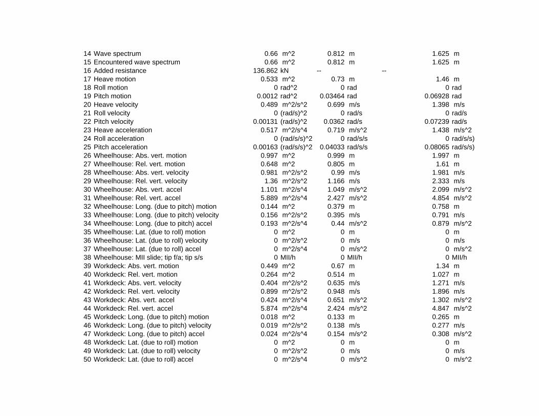
14 Wave spectrum 0.66 m^2 0.812 m 1.625 m15 Encountered wave spectrum 0.66 m^2 0.812 m 1.625 m16 Added resistance 136.862 kN -- --17 Heave motion 0.533 m^2 0.73 m 1.46 m18 Roll motion 0 rad^2 0 rad 0 rad19 Pitch motion 0.0012 rad^2 0.03464 rad 0.06928 rad20 Heave velocity 0.489 m^2/s^2 0.699 m/s 1.398 m/s21 Roll velocity 0 (rad/s)^2 0 rad/s 0 rad/s22 Pitch velocity 0.00131 (rad/s)^2 0.0362 rad/s 0.07239 rad/s23 Heave acceleration 0.517 m^2/s^4 0.719 m/s^2 1.438 m/s^224 Roll acceleration 0 (rad/s/s)^2 0 rad/s/s 0 rad/s/s)25 Pitch acceleration 0.00163 (rad/s/s)^2 0.04033 rad/s/s 0.08065 rad/s/s)26 Wheelhouse: Abs. vert. motion 0.997 m^2 0.999 m 1.997 m27 Wheelhouse: Rel. vert. motion 0.648 m^2 0.805 m 1.61 m28 Wheelhouse: Abs. vert. velocity 0.981 m^2/s^2 0.99 m/s 1.981 m/s29 Wheelhouse: Rel. vert. velocity 1.36 m^2/s^2 1.166 m/s 2.333 m/s30 Wheelhouse: Abs. vert. accel 1.101 m^2/s^4 1.049 m/s^2 2.099 m/s^231 Wheelhouse: Rel. vert. accel 5.889 m^2/s^4 2.427 m/s^2 4.854 m/s^232 Wheelhouse: Long. (due to pitch) motion 0.144 m^2 0.379 m 0.758 m33 Wheelhouse: Long. (due to pitch) velocity 0.156 m^2/s^2 0.395 m/s 0.791 m/s34 Wheelhouse: Long. (due to pitch) accel 0.193 m^2/s^4 0.44 m/s^2 0.879 m/s^235 Wheelhouse: Lat. (due to roll) motion 0 m^2 0 m 0 m36 Wheelhouse: Lat. (due to roll) velocity 0 m^2/s^2 0 m/s 0 m/s37 Wheelhouse: Lat. (due to roll) accel 0 m^2/s^4 0 m/s^2 0 m/s^238 Wheelhouse: MII slide; tip f/a; tip s/s 0 MII/h 0 MII/h 0 MII/h39 Workdeck: Abs. vert. motion 0.449 m^2 0.67 m 1.34 m40 Workdeck: Rel. vert. motion 0.264 m^2 0.514 m 1.027 m41 Workdeck: Abs. vert. velocity 0.404 m^2/s^2 0.635 m/s 1.271 m/s42 Workdeck: Rel. vert. velocity 0.899 m^2/s^2 0.948 m/s 1.896 m/s43 Workdeck: Abs. vert. accel 0.424 m^2/s^4 0.651 m/s^2 1.302 m/s^244 Workdeck: Rel. vert. accel 5.874 m^2/s^4 2.424 m/s^2 4.847 m/s^245 Workdeck: Long. (due to pitch) motion 0.018 m^2 0.133 m 0.265 m46 Workdeck: Long. (due to pitch) velocity 0.019 m^2/s^2 0.138 m/s 0.277 m/s47 Workdeck: Long. (due to pitch) accel 0.024 m^2/s^4 0.154 m/s^2 0.308 m/s^248 Workdeck: Lat. (due to roll) motion 0 m^2 0 m 0 m49 Workdeck: Lat. (due to roll) velocity 0 m^2/s^2 0 m/s 0 m/s50 Workdeck: Lat. (due to roll) accel 0 m^2/s^4 0 m/s^2 0 m/s^2

51 Workdeck: MII slide; tip f/a; tip s/s 0 MII/h 0 MII/h 0 MII/h10, 10 kts; 180, 3.142 rad; Sea State 6 (ITTC (2 Param. Bretschneider): 12.4 s, 5 m)
Item m0 units RMS units Significant amplitude units1 Modal period 12.388 s -- --2 Characteristic wave height 5 m -- --3 Spectrum type ITTC (2 Param. Bretschneid -- --4 Wave heading 3.142 rad -- --5 Vessel Speed 10 kts -- --6 Vessel displacement 2867.584 m^3 -- --7 Vessel GMt 2.924 m -- --8 Vessel trim 0 rad -- --9 Transom method No transom terms -- --
10 Wave force method Arbitrary wave heading -- --11 Added res. method Salvesen -- --12 Pitch gyradius 16.711 m -- --13 Roll gyradius 4.58 m -- --14 Wave spectrum 1.563 m^2 1.25 m 2.5 m15 Encountered wave spectrum 1.563 m^2 1.25 m 2.5 m16 Added resistance 310.662 kN -- --17 Heave motion 1.492 m^2 1.221 m 2.443 m18 Roll motion 0 rad^2 0 rad 0 rad19 Pitch motion 0.00222 rad^2 0.04707 rad 0.09414 rad20 Heave velocity 0.972 m^2/s^2 0.986 m/s 1.971 m/s21 Roll velocity 0 (rad/s)^2 0 rad/s 0 rad/s22 Pitch velocity 0.002 (rad/s)^2 0.04472 rad/s 0.08943 rad/s23 Heave acceleration 0.822 m^2/s^4 0.907 m/s^2 1.813 m/s^224 Roll acceleration 0 (rad/s/s)^2 0 rad/s/s 0 rad/s/s)25 Pitch acceleration 0.00219 (rad/s/s)^2 0.04682 rad/s/s 0.09365 rad/s/s)26 Wheelhouse: Abs. vert. motion 2.346 m^2 1.532 m 3.063 m27 Wheelhouse: Rel. vert. motion 0.792 m^2 0.89 m 1.78 m28 Wheelhouse: Abs. vert. velocity 1.733 m^2/s^2 1.317 m/s 2.633 m/s29 Wheelhouse: Rel. vert. velocity 1.479 m^2/s^2 1.216 m/s 2.433 m/s30 Wheelhouse: Abs. vert. accel 1.629 m^2/s^4 1.276 m/s^2 2.552 m/s^231 Wheelhouse: Rel. vert. accel 5.681 m^2/s^4 2.383 m/s^2 4.767 m/s^232 Wheelhouse: Long. (due to pitch) motion 0.267 m^2 0.517 m 1.033 m33 Wheelhouse: Long. (due to pitch) velocity 0.24 m^2/s^2 0.489 m/s 0.979 m/s34 Wheelhouse: Long. (due to pitch) accel 0.261 m^2/s^4 0.511 m/s^2 1.023 m/s^2

35 Wheelhouse: Lat. (due to roll) motion 0 m^2 0 m 0 m36 Wheelhouse: Lat. (due to roll) velocity 0 m^2/s^2 0 m/s 0 m/s37 Wheelhouse: Lat. (due to roll) accel 0 m^2/s^4 0 m/s^2 0 m/s^238 Wheelhouse: MII slide; tip f/a; tip s/s 0 MII/h 0 MII/h 0 MII/h39 Workdeck: Abs. vert. motion 1.34 m^2 1.158 m 2.315 m40 Workdeck: Rel. vert. motion 0.276 m^2 0.525 m 1.05 m41 Workdeck: Abs. vert. velocity 0.838 m^2/s^2 0.915 m/s 1.831 m/s42 Workdeck: Rel. vert. velocity 0.878 m^2/s^2 0.937 m/s 1.875 m/s43 Workdeck: Abs. vert. accel 0.688 m^2/s^4 0.83 m/s^2 1.659 m/s^244 Workdeck: Rel. vert. accel 5.439 m^2/s^4 2.332 m/s^2 4.664 m/s^245 Workdeck: Long. (due to pitch) motion 0.033 m^2 0.181 m 0.361 m46 Workdeck: Long. (due to pitch) velocity 0.029 m^2/s^2 0.171 m/s 0.342 m/s47 Workdeck: Long. (due to pitch) accel 0.032 m^2/s^4 0.179 m/s^2 0.358 m/s^248 Workdeck: Lat. (due to roll) motion 0 m^2 0 m 0 m49 Workdeck: Lat. (due to roll) velocity 0 m^2/s^2 0 m/s 0 m/s50 Workdeck: Lat. (due to roll) accel 0 m^2/s^4 0 m/s^2 0 m/s^251 Workdeck: MII slide; tip f/a; tip s/s 0 MII/h 0 MII/h 0 MII/h
16, 16 kts; 0, 0 rad; Sea State 4 (ITTC (2 Param. Bretschneider): 8.8 s, 1.88 m)Item m0 units RMS units Significant amplitude units
1 Modal period 8.792 s -- --2 Characteristic wave height 1.88 m -- --3 Spectrum type ITTC (2 Param. Bretschneid -- --4 Wave heading 0 rad -- --5 Vessel Speed 16 kts -- --6 Vessel displacement 2867.584 m^3 -- --7 Vessel GMt 2.924 m -- --8 Vessel trim 0 rad -- --9 Transom method No transom terms -- --
10 Wave force method Arbitrary wave heading -- --11 Added res. method Salvesen -- --12 Pitch gyradius 16.711 m -- --13 Roll gyradius 4.58 m -- --14 Wave spectrum 0.221 m^2 0.47 m 0.94 m15 Encountered wave spectrum 0.221 m^2 0.47 m 0.94 m16 Added resistance 48.544 kN -- --17 Heave motion 0.047 m^2 0.217 m 0.433 m18 Roll motion 0 rad^2 0 rad 0 rad

19 Pitch motion 0.00051 rad^2 0.02247 rad 0.04495 rad20 Heave velocity 0.004 m^2/s^2 0.061 m/s 0.122 m/s21 Roll velocity 0 (rad/s)^2 0 rad/s 0 rad/s22 Pitch velocity 0.00003 (rad/s)^2 0.00568 rad/s 0.01137 rad/s23 Heave acceleration 0 m^2/s^4 0.02 m/s^2 0.039 m/s^224 Roll acceleration 0 (rad/s/s)^2 0 rad/s/s 0 rad/s/s)25 Pitch acceleration 0 (rad/s/s)^2 0.00189 rad/s/s 0.00377 rad/s/s)26 Wheelhouse: Abs. vert. motion 0.13 m^2 0.36 m 0.72 m27 Wheelhouse: Rel. vert. motion 0.051 m^2 0.226 m 0.451 m28 Wheelhouse: Abs. vert. velocity 0.009 m^2/s^2 0.093 m/s 0.185 m/s29 Wheelhouse: Rel. vert. velocity 0.042 m^2/s^2 0.204 m/s 0.408 m/s30 Wheelhouse: Abs. vert. accel 0.001 m^2/s^4 0.028 m/s^2 0.056 m/s^231 Wheelhouse: Rel. vert. accel 2.184 m^2/s^4 1.478 m/s^2 2.956 m/s^232 Wheelhouse: Long. (due to pitch) motion 0.056 m^2 0.237 m 0.474 m33 Wheelhouse: Long. (due to pitch) velocity 0.004 m^2/s^2 0.06 m/s 0.121 m/s34 Wheelhouse: Long. (due to pitch) accel 0 m^2/s^4 0.02 m/s^2 0.04 m/s^235 Wheelhouse: Lat. (due to roll) motion 0 m^2 0 m 0 m36 Wheelhouse: Lat. (due to roll) velocity 0 m^2/s^2 0 m/s 0 m/s37 Wheelhouse: Lat. (due to roll) accel 0 m^2/s^4 0 m/s^2 0 m/s^238 Wheelhouse: MII slide; tip f/a; tip s/s 0 MII/h 0 MII/h 0 MII/h39 Workdeck: Abs. vert. motion 0.063 m^2 0.251 m 0.502 m40 Workdeck: Rel. vert. motion 0.088 m^2 0.296 m 0.592 m41 Workdeck: Abs. vert. velocity 0.005 m^2/s^2 0.071 m/s 0.142 m/s42 Workdeck: Rel. vert. velocity 0.067 m^2/s^2 0.258 m/s 0.516 m/s43 Workdeck: Abs. vert. accel 0.001 m^2/s^4 0.024 m/s^2 0.049 m/s^244 Workdeck: Rel. vert. accel 4.24 m^2/s^4 2.059 m/s^2 4.118 m/s^245 Workdeck: Long. (due to pitch) motion 0.007 m^2 0.083 m 0.166 m46 Workdeck: Long. (due to pitch) velocity 0 m^2/s^2 0.021 m/s 0.042 m/s47 Workdeck: Long. (due to pitch) accel 0 m^2/s^4 0.007 m/s^2 0.014 m/s^248 Workdeck: Lat. (due to roll) motion 0 m^2 0 m 0 m49 Workdeck: Lat. (due to roll) velocity 0 m^2/s^2 0 m/s 0 m/s50 Workdeck: Lat. (due to roll) accel 0 m^2/s^4 0 m/s^2 0 m/s^251 Workdeck: MII slide; tip f/a; tip s/s 0 MII/h 0 MII/h 0 MII/h
16, 16 kts; 0, 0 rad; Sea State 5 (ITTC (2 Param. Bretschneider): 9.7 s, 3.25 m)Item m0 units RMS units Significant amplitude units
1 Modal period 9.691 s -- --2 Characteristic wave height 3.25 m -- --

3 Spectrum type ITTC (2 Param. Bretschneid -- --4 Wave heading 0 rad -- --5 Vessel Speed 16 kts -- --6 Vessel displacement 2867.584 m^3 -- --7 Vessel GMt 2.924 m -- --8 Vessel trim 0 rad -- --9 Transom method No transom terms -- --
10 Wave force method Arbitrary wave heading -- --11 Added res. method Salvesen -- --12 Pitch gyradius 16.711 m -- --13 Roll gyradius 4.58 m -- --14 Wave spectrum 0.66 m^2 0.812 m 1.625 m15 Encountered wave spectrum 0.66 m^2 0.812 m 1.625 m16 Added resistance 138.599 kN -- --17 Heave motion 0.19 m^2 0.436 m 0.873 m18 Roll motion 0 rad^2 0 rad 0 rad19 Pitch motion 0.00149 rad^2 0.03855 rad 0.07709 rad20 Heave velocity 0.016 m^2/s^2 0.125 m/s 0.25 m/s21 Roll velocity 0 (rad/s)^2 0 rad/s 0 rad/s22 Pitch velocity 0.0001 (rad/s)^2 0.01008 rad/s 0.02016 rad/s23 Heave acceleration 0.001 m^2/s^4 0.038 m/s^2 0.076 m/s^224 Roll acceleration 0 (rad/s/s)^2 0 rad/s/s 0 rad/s/s)25 Pitch acceleration 0.00001 (rad/s/s)^2 0.00319 rad/s/s 0.00637 rad/s/s)26 Wheelhouse: Abs. vert. motion 0.416 m^2 0.645 m 1.291 m27 Wheelhouse: Rel. vert. motion 0.133 m^2 0.365 m 0.73 m28 Wheelhouse: Abs. vert. velocity 0.03 m^2/s^2 0.173 m/s 0.345 m/s29 Wheelhouse: Rel. vert. velocity 0.087 m^2/s^2 0.295 m/s 0.59 m/s30 Wheelhouse: Abs. vert. accel 0.003 m^2/s^4 0.051 m/s^2 0.102 m/s^231 Wheelhouse: Rel. vert. accel 4.471 m^2/s^4 2.115 m/s^2 4.229 m/s^232 Wheelhouse: Long. (due to pitch) motion 0.168 m^2 0.41 m 0.819 m33 Wheelhouse: Long. (due to pitch) velocity 0.012 m^2/s^2 0.108 m/s 0.216 m/s34 Wheelhouse: Long. (due to pitch) accel 0.001 m^2/s^4 0.034 m/s^2 0.069 m/s^235 Wheelhouse: Lat. (due to roll) motion 0 m^2 0 m 0 m36 Wheelhouse: Lat. (due to roll) velocity 0 m^2/s^2 0 m/s 0 m/s37 Wheelhouse: Lat. (due to roll) accel 0 m^2/s^4 0 m/s^2 0 m/s^238 Wheelhouse: MII slide; tip f/a; tip s/s 0 MII/h 0 MII/h 0 MII/h39 Workdeck: Abs. vert. motion 0.249 m^2 0.499 m 0.998 m

40 Workdeck: Rel. vert. motion 0.201 m^2 0.448 m 0.896 m41 Workdeck: Abs. vert. velocity 0.02 m^2/s^2 0.143 m/s 0.286 m/s42 Workdeck: Rel. vert. velocity 0.137 m^2/s^2 0.37 m/s 0.739 m/s43 Workdeck: Abs. vert. accel 0.002 m^2/s^4 0.046 m/s^2 0.091 m/s^244 Workdeck: Rel. vert. accel 8.633 m^2/s^4 2.938 m/s^2 5.877 m/s^245 Workdeck: Long. (due to pitch) motion 0.021 m^2 0.143 m 0.287 m46 Workdeck: Long. (due to pitch) velocity 0.001 m^2/s^2 0.038 m/s 0.076 m/s47 Workdeck: Long. (due to pitch) accel 0 m^2/s^4 0.012 m/s^2 0.024 m/s^248 Workdeck: Lat. (due to roll) motion 0 m^2 0 m 0 m49 Workdeck: Lat. (due to roll) velocity 0 m^2/s^2 0 m/s 0 m/s50 Workdeck: Lat. (due to roll) accel 0 m^2/s^4 0 m/s^2 0 m/s^251 Workdeck: MII slide; tip f/a; tip s/s 0 MII/h 0 MII/h 0 MII/h
16, 16 kts; 0, 0 rad; Sea State 6 (ITTC (2 Param. Bretschneider): 12.4 s, 5 m)Item m0 units RMS units Significant amplitude units
1 Modal period 12.388 s -- --2 Characteristic wave height 5 m -- --3 Spectrum type ITTC (2 Param. Bretschneid -- --4 Wave heading 0 rad -- --5 Vessel Speed 16 kts -- --6 Vessel displacement 2867.584 m^3 -- --7 Vessel GMt 2.924 m -- --8 Vessel trim 0 rad -- --9 Transom method No transom terms -- --
10 Wave force method Arbitrary wave heading -- --11 Added res. method Salvesen -- --12 Pitch gyradius 16.711 m -- --13 Roll gyradius 4.58 m -- --14 Wave spectrum 1.563 m^2 1.25 m 2.5 m15 Encountered wave spectrum 1.563 m^2 1.25 m 2.5 m16 Added resistance 274.465 kN -- --17 Heave motion 0.78 m^2 0.883 m 1.766 m18 Roll motion 0 rad^2 0 rad 0 rad19 Pitch motion 0.00272 rad^2 0.0522 rad 0.1044 rad20 Heave velocity 0.063 m^2/s^2 0.252 m/s 0.504 m/s21 Roll velocity 0 (rad/s)^2 0 rad/s 0 rad/s22 Pitch velocity 0.0002 (rad/s)^2 0.0143 rad/s 0.0286 rad/s23 Heave acceleration 0.005 m^2/s^4 0.073 m/s^2 0.146 m/s^2

24 Roll acceleration 0 (rad/s/s)^2 0 rad/s/s 0 rad/s/s)25 Pitch acceleration 0.00002 (rad/s/s)^2 0.0043 rad/s/s 0.0086 rad/s/s)26 Wheelhouse: Abs. vert. motion 1.106 m^2 1.052 m 2.103 m27 Wheelhouse: Rel. vert. motion 0.206 m^2 0.454 m 0.908 m28 Wheelhouse: Abs. vert. velocity 0.086 m^2/s^2 0.293 m/s 0.586 m/s29 Wheelhouse: Rel. vert. velocity 0.084 m^2/s^2 0.29 m/s 0.58 m/s30 Wheelhouse: Abs. vert. accel 0.007 m^2/s^4 0.085 m/s^2 0.17 m/s^231 Wheelhouse: Rel. vert. accel 3.869 m^2/s^4 1.967 m/s^2 3.934 m/s^232 Wheelhouse: Long. (due to pitch) motion 0.318 m^2 0.564 m 1.127 m33 Wheelhouse: Long. (due to pitch) velocity 0.024 m^2/s^2 0.155 m/s 0.311 m/s34 Wheelhouse: Long. (due to pitch) accel 0.002 m^2/s^4 0.047 m/s^2 0.093 m/s^235 Wheelhouse: Lat. (due to roll) motion 0 m^2 0 m 0 m36 Wheelhouse: Lat. (due to roll) velocity 0 m^2/s^2 0 m/s 0 m/s37 Wheelhouse: Lat. (due to roll) accel 0 m^2/s^4 0 m/s^2 0 m/s^238 Wheelhouse: MII slide; tip f/a; tip s/s 0 MII/h 0 MII/h 0 MII/h39 Workdeck: Abs. vert. motion 0.94 m^2 0.97 m 1.939 m40 Workdeck: Rel. vert. motion 0.219 m^2 0.468 m 0.937 m41 Workdeck: Abs. vert. velocity 0.077 m^2/s^2 0.277 m/s 0.554 m/s42 Workdeck: Rel. vert. velocity 0.124 m^2/s^2 0.352 m/s 0.703 m/s43 Workdeck: Abs. vert. accel 0.007 m^2/s^4 0.082 m/s^2 0.163 m/s^244 Workdeck: Rel. vert. accel 7.557 m^2/s^4 2.749 m/s^2 5.498 m/s^245 Workdeck: Long. (due to pitch) motion 0.039 m^2 0.197 m 0.394 m46 Workdeck: Long. (due to pitch) velocity 0.003 m^2/s^2 0.054 m/s 0.109 m/s47 Workdeck: Long. (due to pitch) accel 0 m^2/s^4 0.016 m/s^2 0.033 m/s^248 Workdeck: Lat. (due to roll) motion 0 m^2 0 m 0 m49 Workdeck: Lat. (due to roll) velocity 0 m^2/s^2 0 m/s 0 m/s50 Workdeck: Lat. (due to roll) accel 0 m^2/s^4 0 m/s^2 0 m/s^251 Workdeck: MII slide; tip f/a; tip s/s 0 MII/h 0 MII/h 0 MII/h
16, 16 kts; 30, 0.52 rad; Sea State 4 (ITTC (2 Param. Bretschneider): 8.8 s, 1.88 m)Item m0 units RMS units Significant amplitude units
1 Modal period 8.792 s -- --2 Characteristic wave height 1.88 m -- --3 Spectrum type ITTC (2 Param. Bretschneid -- --4 Wave heading 0.52 rad -- --5 Vessel Speed 16 kts -- --6 Vessel displacement 2867.584 m^3 -- --7 Vessel GMt 2.924 m -- --

8 Vessel trim 0 rad -- --9 Transom method No transom terms -- --
10 Wave force method Arbitrary wave heading -- --11 Added res. method Salvesen -- --12 Pitch gyradius 16.711 m -- --13 Roll gyradius 4.58 m -- --14 Wave spectrum 0.221 m^2 0.47 m 0.94 m15 Encountered wave spectrum 0.221 m^2 0.47 m 0.94 m16 Added resistance 57.902 kN -- --17 Heave motion 0.055 m^2 0.234 m 0.468 m18 Roll motion 0.00102 rad^2 0.03198 rad 0.06396 rad19 Pitch motion 0.00048 rad^2 0.02182 rad 0.04363 rad20 Heave velocity 0.006 m^2/s^2 0.078 m/s 0.156 m/s21 Roll velocity 0.00051 (rad/s)^2 0.02265 rad/s 0.04529 rad/s22 Pitch velocity 0.00005 (rad/s)^2 0.00699 rad/s 0.01397 rad/s23 Heave acceleration 0.001 m^2/s^4 0.028 m/s^2 0.055 m/s^224 Roll acceleration 0.00134 (rad/s/s)^2 0.0366 rad/s/s 0.07321 rad/s/s)25 Pitch acceleration 0.00001 (rad/s/s)^2 0.00235 rad/s/s 0.00471 rad/s/s)26 Wheelhouse: Abs. vert. motion 0.116 m^2 0.341 m 0.682 m27 Wheelhouse: Rel. vert. motion 0.069 m^2 0.264 m 0.527 m28 Wheelhouse: Abs. vert. velocity 0.012 m^2/s^2 0.11 m/s 0.219 m/s29 Wheelhouse: Rel. vert. velocity 0.031 m^2/s^2 0.177 m/s 0.354 m/s30 Wheelhouse: Abs. vert. accel 0.001 m^2/s^4 0.038 m/s^2 0.075 m/s^231 Wheelhouse: Rel. vert. accel 1.094 m^2/s^4 1.046 m/s^2 2.092 m/s^232 Wheelhouse: Long. (due to pitch) motion 0.053 m^2 0.231 m 0.462 m33 Wheelhouse: Long. (due to pitch) velocity 0.006 m^2/s^2 0.074 m/s 0.148 m/s34 Wheelhouse: Long. (due to pitch) accel 0.001 m^2/s^4 0.025 m/s^2 0.05 m/s^235 Wheelhouse: Lat. (due to roll) motion 0.124 m^2 0.353 m 0.705 m36 Wheelhouse: Lat. (due to roll) velocity 0.06 m^2/s^2 0.246 m/s 0.491 m/s37 Wheelhouse: Lat. (due to roll) accel 0.156 m^2/s^4 0.395 m/s^2 0.789 m/s^238 Wheelhouse: MII slide; tip f/a; tip s/s 0 MII/h 0.003 MII/h 0 MII/h39 Workdeck: Abs. vert. motion 0.095 m^2 0.309 m 0.617 m40 Workdeck: Rel. vert. motion 0.065 m^2 0.256 m 0.512 m41 Workdeck: Abs. vert. velocity 0.015 m^2/s^2 0.12 m/s 0.241 m/s42 Workdeck: Rel. vert. velocity 0.05 m^2/s^2 0.224 m/s 0.448 m/s43 Workdeck: Abs. vert. accel 0.013 m^2/s^4 0.115 m/s^2 0.229 m/s^244 Workdeck: Rel. vert. accel 2.256 m^2/s^4 1.502 m/s^2 3.004 m/s^2

45 Workdeck: Long. (due to pitch) motion 0.007 m^2 0.081 m 0.161 m46 Workdeck: Long. (due to pitch) velocity 0.001 m^2/s^2 0.026 m/s 0.052 m/s47 Workdeck: Long. (due to pitch) accel 0 m^2/s^4 0.009 m/s^2 0.018 m/s^248 Workdeck: Lat. (due to roll) motion 0.015 m^2 0.123 m 0.247 m49 Workdeck: Lat. (due to roll) velocity 0.007 m^2/s^2 0.086 m/s 0.172 m/s50 Workdeck: Lat. (due to roll) accel 0.019 m^2/s^4 0.138 m/s^2 0.276 m/s^251 Workdeck: MII slide; tip f/a; tip s/s 0 MII/h 0 MII/h 0 MII/h
16, 16 kts; 30, 0.52 rad; Sea State 5 (ITTC (2 Param. Bretschneider): 9.7 s, 3.25 m)Item m0 units RMS units Significant amplitude units
1 Modal period 9.691 s -- --2 Characteristic wave height 3.25 m -- --3 Spectrum type ITTC (2 Param. Bretschneid -- --4 Wave heading 0.52 rad -- --5 Vessel Speed 16 kts -- --6 Vessel displacement 2867.584 m^3 -- --7 Vessel GMt 2.924 m -- --8 Vessel trim 0 rad -- --9 Transom method No transom terms -- --
10 Wave force method Arbitrary wave heading -- --11 Added res. method Salvesen -- --12 Pitch gyradius 16.711 m -- --13 Roll gyradius 4.58 m -- --14 Wave spectrum 0.66 m^2 0.812 m 1.625 m15 Encountered wave spectrum 0.66 m^2 0.812 m 1.625 m16 Added resistance 159.834 kN -- --17 Heave motion 0.217 m^2 0.465 m 0.931 m18 Roll motion 0.00224 rad^2 0.04737 rad 0.09475 rad19 Pitch motion 0.00139 rad^2 0.03726 rad 0.07452 rad20 Heave velocity 0.024 m^2/s^2 0.155 m/s 0.31 m/s21 Roll velocity 0.00106 (rad/s)^2 0.03254 rad/s 0.06509 rad/s22 Pitch velocity 0.00015 (rad/s)^2 0.01207 rad/s 0.02415 rad/s23 Heave acceleration 0.003 m^2/s^4 0.053 m/s^2 0.106 m/s^224 Roll acceleration 0.00272 (rad/s/s)^2 0.05218 rad/s/s 0.10436 rad/s/s)25 Pitch acceleration 0.00002 (rad/s/s)^2 0.00406 rad/s/s 0.00812 rad/s/s)26 Wheelhouse: Abs. vert. motion 0.376 m^2 0.613 m 1.226 m27 Wheelhouse: Rel. vert. motion 0.175 m^2 0.418 m 0.836 m28 Wheelhouse: Abs. vert. velocity 0.04 m^2/s^2 0.199 m/s 0.398 m/s

29 Wheelhouse: Rel. vert. velocity 0.067 m^2/s^2 0.259 m/s 0.519 m/s30 Wheelhouse: Abs. vert. accel 0.005 m^2/s^4 0.068 m/s^2 0.135 m/s^231 Wheelhouse: Rel. vert. accel 2.238 m^2/s^4 1.496 m/s^2 2.992 m/s^232 Wheelhouse: Long. (due to pitch) motion 0.158 m^2 0.397 m 0.795 m33 Wheelhouse: Long. (due to pitch) velocity 0.017 m^2/s^2 0.129 m/s 0.258 m/s34 Wheelhouse: Long. (due to pitch) accel 0.002 m^2/s^4 0.044 m/s^2 0.087 m/s^235 Wheelhouse: Lat. (due to roll) motion 0.273 m^2 0.523 m 1.046 m36 Wheelhouse: Lat. (due to roll) velocity 0.125 m^2/s^2 0.353 m/s 0.706 m/s37 Wheelhouse: Lat. (due to roll) accel 0.317 m^2/s^4 0.563 m/s^2 1.125 m/s^238 Wheelhouse: MII slide; tip f/a; tip s/s 0 MII/h 0.543 MII/h 0.003 MII/h39 Workdeck: Abs. vert. motion 0.342 m^2 0.585 m 1.17 m40 Workdeck: Rel. vert. motion 0.149 m^2 0.386 m 0.772 m41 Workdeck: Abs. vert. velocity 0.046 m^2/s^2 0.214 m/s 0.429 m/s42 Workdeck: Rel. vert. velocity 0.103 m^2/s^2 0.321 m/s 0.643 m/s43 Workdeck: Abs. vert. accel 0.028 m^2/s^4 0.169 m/s^2 0.337 m/s^244 Workdeck: Rel. vert. accel 4.59 m^2/s^4 2.143 m/s^2 4.285 m/s^245 Workdeck: Long. (due to pitch) motion 0.019 m^2 0.139 m 0.278 m46 Workdeck: Long. (due to pitch) velocity 0.002 m^2/s^2 0.045 m/s 0.09 m/s47 Workdeck: Long. (due to pitch) accel 0 m^2/s^4 0.015 m/s^2 0.03 m/s^248 Workdeck: Lat. (due to roll) motion 0.033 m^2 0.183 m 0.366 m49 Workdeck: Lat. (due to roll) velocity 0.015 m^2/s^2 0.123 m/s 0.247 m/s50 Workdeck: Lat. (due to roll) accel 0.039 m^2/s^4 0.197 m/s^2 0.394 m/s^251 Workdeck: MII slide; tip f/a; tip s/s 0 MII/h 0.013 MII/h 0 MII/h
16, 16 kts; 30, 0.52 rad; Sea State 6 (ITTC (2 Param. Bretschneider): 12.4 s, 5 m)Item m0 units RMS units Significant amplitude units
1 Modal period 12.388 s -- --2 Characteristic wave height 5 m -- --3 Spectrum type ITTC (2 Param. Bretschneid -- --4 Wave heading 0.52 rad -- --5 Vessel Speed 16 kts -- --6 Vessel displacement 2867.584 m^3 -- --7 Vessel GMt 2.924 m -- --8 Vessel trim 0 rad -- --9 Transom method No transom terms -- --
10 Wave force method Arbitrary wave heading -- --11 Added res. method Salvesen -- --12 Pitch gyradius 16.711 m -- --

13 Roll gyradius 4.58 m -- --14 Wave spectrum 1.563 m^2 1.25 m 2.5 m15 Encountered wave spectrum 1.563 m^2 1.25 m 2.5 m16 Added resistance 299.27 kN -- --17 Heave motion 0.843 m^2 0.918 m 1.837 m18 Roll motion 0.00238 rad^2 0.04878 rad 0.09757 rad19 Pitch motion 0.00248 rad^2 0.04977 rad 0.09954 rad20 Heave velocity 0.086 m^2/s^2 0.293 m/s 0.587 m/s21 Roll velocity 0.00098 (rad/s)^2 0.03136 rad/s 0.06272 rad/s22 Pitch velocity 0.00026 (rad/s)^2 0.01623 rad/s 0.03247 rad/s23 Heave acceleration 0.009 m^2/s^4 0.095 m/s^2 0.19 m/s^224 Roll acceleration 0.00242 (rad/s/s)^2 0.04923 rad/s/s 0.09846 rad/s/s)25 Pitch acceleration 0.00003 (rad/s/s)^2 0.00541 rad/s/s 0.01081 rad/s/s)26 Wheelhouse: Abs. vert. motion 1.032 m^2 1.016 m 2.032 m27 Wheelhouse: Rel. vert. motion 0.244 m^2 0.494 m 0.988 m28 Wheelhouse: Abs. vert. velocity 0.106 m^2/s^2 0.325 m/s 0.65 m/s29 Wheelhouse: Rel. vert. velocity 0.069 m^2/s^2 0.263 m/s 0.525 m/s30 Wheelhouse: Abs. vert. accel 0.011 m^2/s^4 0.106 m/s^2 0.212 m/s^231 Wheelhouse: Rel. vert. accel 1.94 m^2/s^4 1.393 m/s^2 2.786 m/s^232 Wheelhouse: Long. (due to pitch) motion 0.292 m^2 0.54 m 1.08 m33 Wheelhouse: Long. (due to pitch) velocity 0.031 m^2/s^2 0.176 m/s 0.353 m/s34 Wheelhouse: Long. (due to pitch) accel 0.003 m^2/s^4 0.059 m/s^2 0.118 m/s^235 Wheelhouse: Lat. (due to roll) motion 0.292 m^2 0.54 m 1.08 m36 Wheelhouse: Lat. (due to roll) velocity 0.116 m^2/s^2 0.341 m/s 0.681 m/s37 Wheelhouse: Lat. (due to roll) accel 0.282 m^2/s^4 0.531 m/s^2 1.062 m/s^238 Wheelhouse: MII slide; tip f/a; tip s/s 0 MII/h 0.478 MII/h 0.002 MII/h39 Workdeck: Abs. vert. motion 1.118 m^2 1.057 m 2.115 m40 Workdeck: Rel. vert. motion 0.166 m^2 0.408 m 0.816 m41 Workdeck: Abs. vert. velocity 0.123 m^2/s^2 0.35 m/s 0.701 m/s42 Workdeck: Rel. vert. velocity 0.095 m^2/s^2 0.308 m/s 0.616 m/s43 Workdeck: Abs. vert. accel 0.034 m^2/s^4 0.184 m/s^2 0.367 m/s^244 Workdeck: Rel. vert. accel 4.026 m^2/s^4 2.006 m/s^2 4.013 m/s^245 Workdeck: Long. (due to pitch) motion 0.036 m^2 0.189 m 0.378 m46 Workdeck: Long. (due to pitch) velocity 0.004 m^2/s^2 0.062 m/s 0.123 m/s47 Workdeck: Long. (due to pitch) accel 0 m^2/s^4 0.021 m/s^2 0.041 m/s^248 Workdeck: Lat. (due to roll) motion 0.036 m^2 0.189 m 0.378 m49 Workdeck: Lat. (due to roll) velocity 0.014 m^2/s^2 0.119 m/s 0.238 m/s
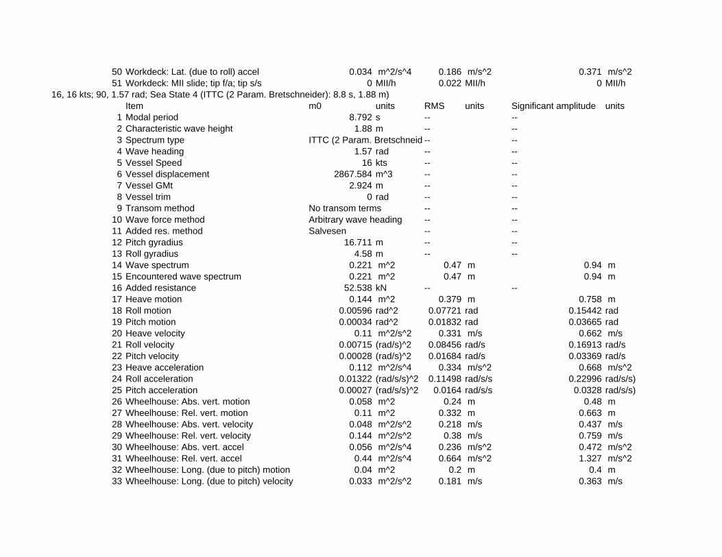
50 Workdeck: Lat. (due to roll) accel 0.034 m^2/s^4 0.186 m/s^2 0.371 m/s^251 Workdeck: MII slide; tip f/a; tip s/s 0 MII/h 0.022 MII/h 0 MII/h
16, 16 kts; 90, 1.57 rad; Sea State 4 (ITTC (2 Param. Bretschneider): 8.8 s, 1.88 m)Item m0 units RMS units Significant amplitude units
1 Modal period 8.792 s -- --2 Characteristic wave height 1.88 m -- --3 Spectrum type ITTC (2 Param. Bretschneid -- --4 Wave heading 1.57 rad -- --5 Vessel Speed 16 kts -- --6 Vessel displacement 2867.584 m^3 -- --7 Vessel GMt 2.924 m -- --8 Vessel trim 0 rad -- --9 Transom method No transom terms -- --
10 Wave force method Arbitrary wave heading -- --11 Added res. method Salvesen -- --12 Pitch gyradius 16.711 m -- --13 Roll gyradius 4.58 m -- --14 Wave spectrum 0.221 m^2 0.47 m 0.94 m15 Encountered wave spectrum 0.221 m^2 0.47 m 0.94 m16 Added resistance 52.538 kN -- --17 Heave motion 0.144 m^2 0.379 m 0.758 m18 Roll motion 0.00596 rad^2 0.07721 rad 0.15442 rad19 Pitch motion 0.00034 rad^2 0.01832 rad 0.03665 rad20 Heave velocity 0.11 m^2/s^2 0.331 m/s 0.662 m/s21 Roll velocity 0.00715 (rad/s)^2 0.08456 rad/s 0.16913 rad/s22 Pitch velocity 0.00028 (rad/s)^2 0.01684 rad/s 0.03369 rad/s23 Heave acceleration 0.112 m^2/s^4 0.334 m/s^2 0.668 m/s^224 Roll acceleration 0.01322 (rad/s/s)^2 0.11498 rad/s/s 0.22996 rad/s/s)25 Pitch acceleration 0.00027 (rad/s/s)^2 0.0164 rad/s/s 0.0328 rad/s/s)26 Wheelhouse: Abs. vert. motion 0.058 m^2 0.24 m 0.48 m27 Wheelhouse: Rel. vert. motion 0.11 m^2 0.332 m 0.663 m28 Wheelhouse: Abs. vert. velocity 0.048 m^2/s^2 0.218 m/s 0.437 m/s29 Wheelhouse: Rel. vert. velocity 0.144 m^2/s^2 0.38 m/s 0.759 m/s30 Wheelhouse: Abs. vert. accel 0.056 m^2/s^4 0.236 m/s^2 0.472 m/s^231 Wheelhouse: Rel. vert. accel 0.44 m^2/s^4 0.664 m/s^2 1.327 m/s^232 Wheelhouse: Long. (due to pitch) motion 0.04 m^2 0.2 m 0.4 m33 Wheelhouse: Long. (due to pitch) velocity 0.033 m^2/s^2 0.181 m/s 0.363 m/s

34 Wheelhouse: Long. (due to pitch) accel 0.03 m^2/s^4 0.174 m/s^2 0.348 m/s^235 Wheelhouse: Lat. (due to roll) motion 0.728 m^2 0.853 m 1.707 m36 Wheelhouse: Lat. (due to roll) velocity 0.851 m^2/s^2 0.923 m/s 1.845 m/s37 Wheelhouse: Lat. (due to roll) accel 1.554 m^2/s^4 1.247 m/s^2 2.493 m/s^238 Wheelhouse: MII slide; tip f/a; tip s/s 0 MII/h 5.342 MII/h 0.371 MII/h39 Workdeck: Abs. vert. motion 0.428 m^2 0.654 m 1.309 m40 Workdeck: Rel. vert. motion 0.081 m^2 0.285 m 0.571 m41 Workdeck: Abs. vert. velocity 0.388 m^2/s^2 0.623 m/s 1.245 m/s42 Workdeck: Rel. vert. velocity 0.109 m^2/s^2 0.33 m/s 0.66 m/s43 Workdeck: Abs. vert. accel 0.474 m^2/s^4 0.688 m/s^2 1.376 m/s^244 Workdeck: Rel. vert. accel 0.362 m^2/s^4 0.602 m/s^2 1.203 m/s^245 Workdeck: Long. (due to pitch) motion 0.005 m^2 0.07 m 0.14 m46 Workdeck: Long. (due to pitch) velocity 0.004 m^2/s^2 0.063 m/s 0.127 m/s47 Workdeck: Long. (due to pitch) accel 0.004 m^2/s^4 0.061 m/s^2 0.122 m/s^248 Workdeck: Lat. (due to roll) motion 0.089 m^2 0.299 m 0.597 m49 Workdeck: Lat. (due to roll) velocity 0.104 m^2/s^2 0.323 m/s 0.645 m/s50 Workdeck: Lat. (due to roll) accel 0.19 m^2/s^4 0.436 m/s^2 0.872 m/s^251 Workdeck: MII slide; tip f/a; tip s/s 0 MII/h 0.151 MII/h 0.003 MII/h
16, 16 kts; 90, 1.57 rad; Sea State 5 (ITTC (2 Param. Bretschneider): 9.7 s, 3.25 m)Item m0 units RMS units Significant amplitude units
1 Modal period 9.691 s -- --2 Characteristic wave height 3.25 m -- --3 Spectrum type ITTC (2 Param. Bretschneid -- --4 Wave heading 1.57 rad -- --5 Vessel Speed 16 kts -- --6 Vessel displacement 2867.584 m^3 -- --7 Vessel GMt 2.924 m -- --8 Vessel trim 0 rad -- --9 Transom method No transom terms -- --
10 Wave force method Arbitrary wave heading -- --11 Added res. method Salvesen -- --12 Pitch gyradius 16.711 m -- --13 Roll gyradius 4.58 m -- --14 Wave spectrum 0.66 m^2 0.812 m 1.625 m15 Encountered wave spectrum 0.66 m^2 0.812 m 1.625 m16 Added resistance 149.234 kN -- --17 Heave motion 0.459 m^2 0.678 m 1.355 m

18 Roll motion 0.01404 rad^2 0.1185 rad 0.237 rad19 Pitch motion 0.00085 rad^2 0.02922 rad 0.05844 rad20 Heave velocity 0.294 m^2/s^2 0.542 m/s 1.084 m/s21 Roll velocity 0.01596 (rad/s)^2 0.12634 rad/s 0.25269 rad/s22 Pitch velocity 0.00068 (rad/s)^2 0.02616 rad/s 0.05232 rad/s23 Heave acceleration 0.264 m^2/s^4 0.514 m/s^2 1.028 m/s^224 Roll acceleration 0.02813 (rad/s/s)^2 0.16772 rad/s/s 0.33545 rad/s/s)25 Pitch acceleration 0.00062 (rad/s/s)^2 0.02498 rad/s/s 0.04996 rad/s/s)26 Wheelhouse: Abs. vert. motion 0.197 m^2 0.444 m 0.888 m27 Wheelhouse: Rel. vert. motion 0.276 m^2 0.526 m 1.051 m28 Wheelhouse: Abs. vert. velocity 0.128 m^2/s^2 0.357 m/s 0.715 m/s29 Wheelhouse: Rel. vert. velocity 0.325 m^2/s^2 0.57 m/s 1.14 m/s30 Wheelhouse: Abs. vert. accel 0.129 m^2/s^4 0.359 m/s^2 0.717 m/s^231 Wheelhouse: Rel. vert. accel 0.918 m^2/s^4 0.958 m/s^2 1.916 m/s^232 Wheelhouse: Long. (due to pitch) motion 0.104 m^2 0.322 m 0.644 m33 Wheelhouse: Long. (due to pitch) velocity 0.08 m^2/s^2 0.283 m/s 0.567 m/s34 Wheelhouse: Long. (due to pitch) accel 0.071 m^2/s^4 0.266 m/s^2 0.533 m/s^235 Wheelhouse: Lat. (due to roll) motion 1.733 m^2 1.316 m 2.633 m36 Wheelhouse: Lat. (due to roll) velocity 1.912 m^2/s^2 1.383 m/s 2.765 m/s37 Wheelhouse: Lat. (due to roll) accel 3.314 m^2/s^4 1.82 m/s^2 3.641 m/s^238 Wheelhouse: MII slide; tip f/a; tip s/s 0 MII/h 17.626 MII/h 4.831 MII/h39 Workdeck: Abs. vert. motion 1.184 m^2 1.088 m 2.177 m40 Workdeck: Rel. vert. motion 0.202 m^2 0.449 m 0.898 m41 Workdeck: Abs. vert. velocity 0.947 m^2/s^2 0.973 m/s 1.946 m/s42 Workdeck: Rel. vert. velocity 0.243 m^2/s^2 0.493 m/s 0.986 m/s43 Workdeck: Abs. vert. accel 1.065 m^2/s^4 1.032 m/s^2 2.064 m/s^244 Workdeck: Rel. vert. accel 0.752 m^2/s^4 0.867 m/s^2 1.734 m/s^245 Workdeck: Long. (due to pitch) motion 0.013 m^2 0.113 m 0.225 m46 Workdeck: Long. (due to pitch) velocity 0.01 m^2/s^2 0.099 m/s 0.198 m/s47 Workdeck: Long. (due to pitch) accel 0.009 m^2/s^4 0.093 m/s^2 0.186 m/s^248 Workdeck: Lat. (due to roll) motion 0.212 m^2 0.46 m 0.921 m49 Workdeck: Lat. (due to roll) velocity 0.234 m^2/s^2 0.484 m/s 0.967 m/s50 Workdeck: Lat. (due to roll) accel 0.405 m^2/s^4 0.637 m/s^2 1.273 m/s^251 Workdeck: MII slide; tip f/a; tip s/s 0 MII/h 2.467 MII/h 0.368 MII/h
16, 16 kts; 90, 1.57 rad; Sea State 6 (ITTC (2 Param. Bretschneider): 12.4 s, 5 m)Item m0 units RMS units Significant amplitude units
1 Modal period 12.388 s -- --

2 Characteristic wave height 5 m -- --3 Spectrum type ITTC (2 Param. Bretschneid -- --4 Wave heading 1.57 rad -- --5 Vessel Speed 16 kts -- --6 Vessel displacement 2867.584 m^3 -- --7 Vessel GMt 2.924 m -- --8 Vessel trim 0 rad -- --9 Transom method No transom terms -- --
10 Wave force method Arbitrary wave heading -- --11 Added res. method Salvesen -- --12 Pitch gyradius 16.711 m -- --13 Roll gyradius 4.58 m -- --14 Wave spectrum 1.563 m^2 1.25 m 2.5 m15 Encountered wave spectrum 1.563 m^2 1.25 m 2.5 m16 Added resistance 298.541 kN -- --17 Heave motion 1.27 m^2 1.127 m 2.254 m18 Roll motion 0.01622 rad^2 0.12734 rad 0.25468 rad19 Pitch motion 0.00111 rad^2 0.03327 rad 0.06653 rad20 Heave velocity 0.517 m^2/s^2 0.719 m/s 1.438 m/s21 Roll velocity 0.01652 (rad/s)^2 0.12854 rad/s 0.25708 rad/s22 Pitch velocity 0.0008 (rad/s)^2 0.02827 rad/s 0.05654 rad/s23 Heave acceleration 0.33 m^2/s^4 0.574 m/s^2 1.148 m/s^224 Roll acceleration 0.02686 (rad/s/s)^2 0.16389 rad/s/s 0.32778 rad/s/s)25 Pitch acceleration 0.00068 (rad/s/s)^2 0.02605 rad/s/s 0.05209 rad/s/s)26 Wheelhouse: Abs. vert. motion 0.742 m^2 0.861 m 1.723 m27 Wheelhouse: Rel. vert. motion 0.359 m^2 0.599 m 1.198 m28 Wheelhouse: Abs. vert. velocity 0.262 m^2/s^2 0.512 m/s 1.023 m/s29 Wheelhouse: Rel. vert. velocity 0.348 m^2/s^2 0.59 m/s 1.18 m/s30 Wheelhouse: Abs. vert. accel 0.162 m^2/s^4 0.402 m/s^2 0.805 m/s^231 Wheelhouse: Rel. vert. accel 0.853 m^2/s^4 0.924 m/s^2 1.847 m/s^232 Wheelhouse: Long. (due to pitch) motion 0.14 m^2 0.374 m 0.748 m33 Wheelhouse: Long. (due to pitch) velocity 0.096 m^2/s^2 0.31 m/s 0.62 m/s34 Wheelhouse: Long. (due to pitch) accel 0.078 m^2/s^4 0.28 m/s^2 0.56 m/s^235 Wheelhouse: Lat. (due to roll) motion 2.04 m^2 1.428 m 2.857 m36 Wheelhouse: Lat. (due to roll) velocity 2.001 m^2/s^2 1.415 m/s 2.829 m/s37 Wheelhouse: Lat. (due to roll) accel 3.177 m^2/s^4 1.782 m/s^2 3.565 m/s^238 Wheelhouse: MII slide; tip f/a; tip s/s 0 MII/h 16.05 MII/h 4.101 MII/h

39 Workdeck: Abs. vert. motion 2.295 m^2 1.515 m 3.03 m40 Workdeck: Rel. vert. motion 0.278 m^2 0.528 m 1.055 m41 Workdeck: Abs. vert. velocity 1.275 m^2/s^2 1.129 m/s 2.258 m/s42 Workdeck: Rel. vert. velocity 0.261 m^2/s^2 0.511 m/s 1.022 m/s43 Workdeck: Abs. vert. accel 1.149 m^2/s^4 1.072 m/s^2 2.143 m/s^244 Workdeck: Rel. vert. accel 0.696 m^2/s^4 0.834 m/s^2 1.668 m/s^245 Workdeck: Long. (due to pitch) motion 0.017 m^2 0.131 m 0.262 m46 Workdeck: Long. (due to pitch) velocity 0.012 m^2/s^2 0.108 m/s 0.217 m/s47 Workdeck: Long. (due to pitch) accel 0.01 m^2/s^4 0.098 m/s^2 0.196 m/s^248 Workdeck: Lat. (due to roll) motion 0.25 m^2 0.5 m 0.999 m49 Workdeck: Lat. (due to roll) velocity 0.245 m^2/s^2 0.495 m/s 0.99 m/s50 Workdeck: Lat. (due to roll) accel 0.389 m^2/s^4 0.623 m/s^2 1.247 m/s^251 Workdeck: MII slide; tip f/a; tip s/s 0 MII/h 3.396 MII/h 0.66 MII/h
16, 16 kts; 140, 2.44 rad; Sea State 4 (ITTC (2 Param. Bretschneider): 8.8 s, 1.88 m)Item m0 units RMS units Significant amplitude units
1 Modal period 8.792 s -- --2 Characteristic wave height 1.88 m -- --3 Spectrum type ITTC (2 Param. Bretschneid -- --4 Wave heading 2.44 rad -- --5 Vessel Speed 16 kts -- --6 Vessel displacement 2867.584 m^3 -- --7 Vessel GMt 2.924 m -- --8 Vessel trim 0 rad -- --9 Transom method No transom terms -- --
10 Wave force method Arbitrary wave heading -- --11 Added res. method Salvesen -- --12 Pitch gyradius 16.711 m -- --13 Roll gyradius 4.58 m -- --14 Wave spectrum 0.221 m^2 0.47 m 0.94 m15 Encountered wave spectrum 0.221 m^2 0.47 m 0.94 m16 Added resistance 46.935 kN -- --17 Heave motion 0.252 m^2 0.502 m 1.004 m18 Roll motion 0.00076 rad^2 0.02752 rad 0.05504 rad19 Pitch motion 0.00045 rad^2 0.02113 rad 0.04227 rad20 Heave velocity 0.315 m^2/s^2 0.561 m/s 1.123 m/s21 Roll velocity 0.00112 (rad/s)^2 0.03348 rad/s 0.06696 rad/s22 Pitch velocity 0.00065 (rad/s)^2 0.02546 rad/s 0.05092 rad/s

23 Heave acceleration 0.44 m^2/s^4 0.663 m/s^2 1.326 m/s^224 Roll acceleration 0.00266 (rad/s/s)^2 0.05156 rad/s/s 0.10312 rad/s/s)25 Pitch acceleration 0.00106 (rad/s/s)^2 0.03252 rad/s/s 0.06504 rad/s/s)26 Wheelhouse: Abs. vert. motion 0.371 m^2 0.609 m 1.219 m27 Wheelhouse: Rel. vert. motion 0.297 m^2 0.545 m 1.09 m28 Wheelhouse: Abs. vert. velocity 0.475 m^2/s^2 0.69 m/s 1.379 m/s29 Wheelhouse: Rel. vert. velocity 0.774 m^2/s^2 0.88 m/s 1.759 m/s30 Wheelhouse: Abs. vert. accel 0.675 m^2/s^4 0.821 m/s^2 1.643 m/s^231 Wheelhouse: Rel. vert. accel 3.938 m^2/s^4 1.984 m/s^2 3.969 m/s^232 Wheelhouse: Long. (due to pitch) motion 0.054 m^2 0.231 m 0.463 m33 Wheelhouse: Long. (due to pitch) velocity 0.077 m^2/s^2 0.278 m/s 0.557 m/s34 Wheelhouse: Long. (due to pitch) accel 0.126 m^2/s^4 0.355 m/s^2 0.71 m/s^235 Wheelhouse: Lat. (due to roll) motion 0.091 m^2 0.301 m 0.602 m36 Wheelhouse: Lat. (due to roll) velocity 0.133 m^2/s^2 0.365 m/s 0.731 m/s37 Wheelhouse: Lat. (due to roll) accel 0.314 m^2/s^4 0.56 m/s^2 1.12 m/s^238 Wheelhouse: MII slide; tip f/a; tip s/s 0 MII/h 0.017 MII/h 0 MII/h39 Workdeck: Abs. vert. motion 0.317 m^2 0.563 m 1.126 m40 Workdeck: Rel. vert. motion 0.181 m^2 0.425 m 0.85 m41 Workdeck: Abs. vert. velocity 0.402 m^2/s^2 0.634 m/s 1.269 m/s42 Workdeck: Rel. vert. velocity 0.561 m^2/s^2 0.749 m/s 1.498 m/s43 Workdeck: Abs. vert. accel 0.575 m^2/s^4 0.758 m/s^2 1.517 m/s^244 Workdeck: Rel. vert. accel 3.505 m^2/s^4 1.872 m/s^2 3.745 m/s^245 Workdeck: Long. (due to pitch) motion 0.007 m^2 0.081 m 0.162 m46 Workdeck: Long. (due to pitch) velocity 0.009 m^2/s^2 0.097 m/s 0.195 m/s47 Workdeck: Long. (due to pitch) accel 0.015 m^2/s^4 0.124 m/s^2 0.248 m/s^248 Workdeck: Lat. (due to roll) motion 0.011 m^2 0.105 m 0.211 m49 Workdeck: Lat. (due to roll) velocity 0.016 m^2/s^2 0.128 m/s 0.256 m/s50 Workdeck: Lat. (due to roll) accel 0.038 m^2/s^4 0.196 m/s^2 0.392 m/s^251 Workdeck: MII slide; tip f/a; tip s/s 0 MII/h 0 MII/h 0 MII/h
16, 16 kts; 140, 2.44 rad; Sea State 5 (ITTC (2 Param. Bretschneider): 9.7 s, 3.25 m)Item m0 units RMS units Significant amplitude units
1 Modal period 9.691 s -- --2 Characteristic wave height 3.25 m -- --3 Spectrum type ITTC (2 Param. Bretschneid -- --4 Wave heading 2.44 rad -- --5 Vessel Speed 16 kts -- --6 Vessel displacement 2867.584 m^3 -- --

7 Vessel GMt 2.924 m -- --8 Vessel trim 0 rad -- --9 Transom method No transom terms -- --
10 Wave force method Arbitrary wave heading -- --11 Added res. method Salvesen -- --12 Pitch gyradius 16.711 m -- --13 Roll gyradius 4.58 m -- --14 Wave spectrum 0.66 m^2 0.812 m 1.625 m15 Encountered wave spectrum 0.66 m^2 0.812 m 1.625 m16 Added resistance 147.322 kN -- --17 Heave motion 0.818 m^2 0.904 m 1.808 m18 Roll motion 0.00228 rad^2 0.0478 rad 0.0956 rad19 Pitch motion 0.00129 rad^2 0.03589 rad 0.07178 rad20 Heave velocity 0.925 m^2/s^2 0.962 m/s 1.924 m/s21 Roll velocity 0.00306 (rad/s)^2 0.05531 rad/s 0.11063 rad/s22 Pitch velocity 0.00175 (rad/s)^2 0.04183 rad/s 0.08367 rad/s23 Heave acceleration 1.207 m^2/s^4 1.099 m/s^2 2.197 m/s^224 Roll acceleration 0.00637 (rad/s/s)^2 0.07984 rad/s/s 0.15968 rad/s/s)25 Pitch acceleration 0.00272 (rad/s/s)^2 0.05212 rad/s/s 0.10425 rad/s/s)26 Wheelhouse: Abs. vert. motion 1.169 m^2 1.081 m 2.162 m27 Wheelhouse: Rel. vert. motion 0.732 m^2 0.856 m 1.711 m28 Wheelhouse: Abs. vert. velocity 1.371 m^2/s^2 1.171 m/s 2.342 m/s29 Wheelhouse: Rel. vert. velocity 1.787 m^2/s^2 1.337 m/s 2.674 m/s30 Wheelhouse: Abs. vert. accel 1.833 m^2/s^4 1.354 m/s^2 2.708 m/s^231 Wheelhouse: Rel. vert. accel 8.471 m^2/s^4 2.911 m/s^2 5.821 m/s^232 Wheelhouse: Long. (due to pitch) motion 0.155 m^2 0.393 m 0.787 m33 Wheelhouse: Long. (due to pitch) velocity 0.209 m^2/s^2 0.458 m/s 0.915 m/s34 Wheelhouse: Long. (due to pitch) accel 0.324 m^2/s^4 0.569 m/s^2 1.139 m/s^235 Wheelhouse: Lat. (due to roll) motion 0.274 m^2 0.524 m 1.047 m36 Wheelhouse: Lat. (due to roll) velocity 0.365 m^2/s^2 0.604 m/s 1.208 m/s37 Wheelhouse: Lat. (due to roll) accel 0.754 m^2/s^4 0.868 m/s^2 1.737 m/s^238 Wheelhouse: MII slide; tip f/a; tip s/s 0 MII/h 0.732 MII/h 0.071 MII/h39 Workdeck: Abs. vert. motion 1.013 m^2 1.006 m 2.012 m40 Workdeck: Rel. vert. motion 0.441 m^2 0.664 m 1.328 m41 Workdeck: Abs. vert. velocity 1.17 m^2/s^2 1.081 m/s 2.163 m/s42 Workdeck: Rel. vert. velocity 1.265 m^2/s^2 1.125 m/s 2.249 m/s43 Workdeck: Abs. vert. accel 1.563 m^2/s^4 1.25 m/s^2 2.501 m/s^2

44 Workdeck: Rel. vert. accel 7.437 m^2/s^4 2.727 m/s^2 5.454 m/s^245 Workdeck: Long. (due to pitch) motion 0.019 m^2 0.138 m 0.275 m46 Workdeck: Long. (due to pitch) velocity 0.026 m^2/s^2 0.16 m/s 0.32 m/s47 Workdeck: Long. (due to pitch) accel 0.04 m^2/s^4 0.199 m/s^2 0.398 m/s^248 Workdeck: Lat. (due to roll) motion 0.034 m^2 0.183 m 0.366 m49 Workdeck: Lat. (due to roll) velocity 0.045 m^2/s^2 0.211 m/s 0.423 m/s50 Workdeck: Lat. (due to roll) accel 0.092 m^2/s^4 0.304 m/s^2 0.607 m/s^251 Workdeck: MII slide; tip f/a; tip s/s 0 MII/h 0.009 MII/h 0 MII/h
16, 16 kts; 140, 2.44 rad; Sea State 6 (ITTC (2 Param. Bretschneider): 12.4 s, 5 m)Item m0 units RMS units Significant amplitude units
1 Modal period 12.388 s -- --2 Characteristic wave height 5 m -- --3 Spectrum type ITTC (2 Param. Bretschneid -- --4 Wave heading 2.44 rad -- --5 Vessel Speed 16 kts -- --6 Vessel displacement 2867.584 m^3 -- --7 Vessel GMt 2.924 m -- --8 Vessel trim 0 rad -- --9 Transom method No transom terms -- --
10 Wave force method Arbitrary wave heading -- --11 Added res. method Salvesen -- --12 Pitch gyradius 16.711 m -- --13 Roll gyradius 4.58 m -- --14 Wave spectrum 1.563 m^2 1.25 m 2.5 m15 Encountered wave spectrum 1.563 m^2 1.25 m 2.5 m16 Added resistance 327.986 kN -- --17 Heave motion 1.958 m^2 1.399 m 2.799 m18 Roll motion 0.00389 rad^2 0.06237 rad 0.12475 rad19 Pitch motion 0.0021 rad^2 0.04578 rad 0.09156 rad20 Heave velocity 1.614 m^2/s^2 1.271 m/s 2.541 m/s21 Roll velocity 0.00438 (rad/s)^2 0.0662 rad/s 0.1324 rad/s22 Pitch velocity 0.00244 (rad/s)^2 0.04936 rad/s 0.09873 rad/s23 Heave acceleration 1.747 m^2/s^4 1.322 m/s^2 2.644 m/s^224 Roll acceleration 0.00747 (rad/s/s)^2 0.08643 rad/s/s 0.17286 rad/s/s)25 Pitch acceleration 0.00343 (rad/s/s)^2 0.05853 rad/s/s 0.11705 rad/s/s)26 Wheelhouse: Abs. vert. motion 2.532 m^2 1.591 m 3.182 m27 Wheelhouse: Rel. vert. motion 0.869 m^2 0.932 m 1.864 m

28 Wheelhouse: Abs. vert. velocity 2.255 m^2/s^2 1.502 m/s 3.003 m/s29 Wheelhouse: Rel. vert. velocity 1.923 m^2/s^2 1.387 m/s 2.773 m/s30 Wheelhouse: Abs. vert. accel 2.574 m^2/s^4 1.604 m/s^2 3.209 m/s^231 Wheelhouse: Rel. vert. accel 8.197 m^2/s^4 2.863 m/s^2 5.726 m/s^232 Wheelhouse: Long. (due to pitch) motion 0.253 m^2 0.503 m 1.006 m33 Wheelhouse: Long. (due to pitch) velocity 0.293 m^2/s^2 0.541 m/s 1.082 m/s34 Wheelhouse: Long. (due to pitch) accel 0.409 m^2/s^4 0.64 m/s^2 1.28 m/s^235 Wheelhouse: Lat. (due to roll) motion 0.47 m^2 0.686 m 1.371 m36 Wheelhouse: Lat. (due to roll) velocity 0.525 m^2/s^2 0.725 m/s 1.45 m/s37 Wheelhouse: Lat. (due to roll) accel 0.887 m^2/s^4 0.942 m/s^2 1.883 m/s^238 Wheelhouse: MII slide; tip f/a; tip s/s 0 MII/h 0.816 MII/h 0.1 MII/h39 Workdeck: Abs. vert. motion 2.288 m^2 1.512 m 3.025 m40 Workdeck: Rel. vert. motion 0.531 m^2 0.728 m 1.457 m41 Workdeck: Abs. vert. velocity 1.972 m^2/s^2 1.404 m/s 2.809 m/s42 Workdeck: Rel. vert. velocity 1.323 m^2/s^2 1.15 m/s 2.301 m/s43 Workdeck: Abs. vert. accel 2.215 m^2/s^4 1.488 m/s^2 2.976 m/s^244 Workdeck: Rel. vert. accel 7.045 m^2/s^4 2.654 m/s^2 5.308 m/s^245 Workdeck: Long. (due to pitch) motion 0.031 m^2 0.176 m 0.352 m46 Workdeck: Long. (due to pitch) velocity 0.036 m^2/s^2 0.189 m/s 0.378 m/s47 Workdeck: Long. (due to pitch) accel 0.05 m^2/s^4 0.224 m/s^2 0.448 m/s^248 Workdeck: Lat. (due to roll) motion 0.057 m^2 0.24 m 0.48 m49 Workdeck: Lat. (due to roll) velocity 0.064 m^2/s^2 0.254 m/s 0.507 m/s50 Workdeck: Lat. (due to roll) accel 0.108 m^2/s^4 0.329 m/s^2 0.659 m/s^251 Workdeck: MII slide; tip f/a; tip s/s 0 MII/h 0.148 MII/h 0.018 MII/h
16, 16 kts; 180, 3.142 rad; Sea State 4 (ITTC (2 Param. Bretschneider): 8.8 s, 1.88 m)Item m0 units RMS units Significant amplitude units
1 Modal period 8.792 s -- --2 Characteristic wave height 1.88 m -- --3 Spectrum type ITTC (2 Param. Bretschneid -- --4 Wave heading 3.142 rad -- --5 Vessel Speed 16 kts -- --6 Vessel displacement 2867.584 m^3 -- --7 Vessel GMt 2.924 m -- --8 Vessel trim 0 rad -- --9 Transom method No transom terms -- --
10 Wave force method Arbitrary wave heading -- --11 Added res. method Salvesen -- --

12 Pitch gyradius 16.711 m -- --13 Roll gyradius 4.58 m -- --14 Wave spectrum 0.221 m^2 0.47 m 0.94 m15 Encountered wave spectrum 0.221 m^2 0.47 m 0.94 m16 Added resistance 38.416 kN -- --17 Heave motion 0.203 m^2 0.451 m 0.902 m18 Roll motion 0 rad^2 0 rad 0 rad19 Pitch motion 0.00036 rad^2 0.01907 rad 0.03814 rad20 Heave velocity 0.259 m^2/s^2 0.509 m/s 1.019 m/s21 Roll velocity 0 (rad/s)^2 0 rad/s 0 rad/s22 Pitch velocity 0.00052 (rad/s)^2 0.02287 rad/s 0.04573 rad/s23 Heave acceleration 0.361 m^2/s^4 0.601 m/s^2 1.202 m/s^224 Roll acceleration 0 (rad/s/s)^2 0 rad/s/s 0 rad/s/s)25 Pitch acceleration 0.00083 (rad/s/s)^2 0.02876 rad/s/s 0.05752 rad/s/s)26 Wheelhouse: Abs. vert. motion 0.338 m^2 0.581 m 1.163 m27 Wheelhouse: Rel. vert. motion 0.38 m^2 0.617 m 1.234 m28 Wheelhouse: Abs. vert. velocity 0.441 m^2/s^2 0.664 m/s 1.328 m/s29 Wheelhouse: Rel. vert. velocity 0.975 m^2/s^2 0.987 m/s 1.974 m/s30 Wheelhouse: Abs. vert. accel 0.629 m^2/s^4 0.793 m/s^2 1.587 m/s^231 Wheelhouse: Rel. vert. accel 5.146 m^2/s^4 2.269 m/s^2 4.537 m/s^232 Wheelhouse: Long. (due to pitch) motion 0.044 m^2 0.209 m 0.417 m33 Wheelhouse: Long. (due to pitch) velocity 0.062 m^2/s^2 0.25 m/s 0.5 m/s34 Wheelhouse: Long. (due to pitch) accel 0.098 m^2/s^4 0.314 m/s^2 0.627 m/s^235 Wheelhouse: Lat. (due to roll) motion 0 m^2 0 m 0 m36 Wheelhouse: Lat. (due to roll) velocity 0 m^2/s^2 0 m/s 0 m/s37 Wheelhouse: Lat. (due to roll) accel 0 m^2/s^4 0 m/s^2 0 m/s^238 Wheelhouse: MII slide; tip f/a; tip s/s 0 MII/h 0 MII/h 0 MII/h39 Workdeck: Abs. vert. motion 0.181 m^2 0.425 m 0.851 m40 Workdeck: Rel. vert. motion 0.201 m^2 0.448 m 0.896 m41 Workdeck: Abs. vert. velocity 0.233 m^2/s^2 0.482 m/s 0.965 m/s42 Workdeck: Rel. vert. velocity 0.713 m^2/s^2 0.844 m/s 1.688 m/s43 Workdeck: Abs. vert. accel 0.328 m^2/s^4 0.573 m/s^2 1.146 m/s^244 Workdeck: Rel. vert. accel 4.996 m^2/s^4 2.235 m/s^2 4.47 m/s^245 Workdeck: Long. (due to pitch) motion 0.005 m^2 0.073 m 0.146 m46 Workdeck: Long. (due to pitch) velocity 0.008 m^2/s^2 0.087 m/s 0.175 m/s47 Workdeck: Long. (due to pitch) accel 0.012 m^2/s^4 0.11 m/s^2 0.219 m/s^248 Workdeck: Lat. (due to roll) motion 0 m^2 0 m 0 m

49 Workdeck: Lat. (due to roll) velocity 0 m^2/s^2 0 m/s 0 m/s50 Workdeck: Lat. (due to roll) accel 0 m^2/s^4 0 m/s^2 0 m/s^251 Workdeck: MII slide; tip f/a; tip s/s 0 MII/h 0 MII/h 0 MII/h
16, 16 kts; 180, 3.142 rad; Sea State 5 (ITTC (2 Param. Bretschneider): 9.7 s, 3.25 m)Item m0 units RMS units Significant amplitude units
1 Modal period 9.691 s -- --2 Characteristic wave height 3.25 m -- --3 Spectrum type ITTC (2 Param. Bretschneid -- --4 Wave heading 3.142 rad -- --5 Vessel Speed 16 kts -- --6 Vessel displacement 2867.584 m^3 -- --7 Vessel GMt 2.924 m -- --8 Vessel trim 0 rad -- --9 Transom method No transom terms -- --
10 Wave force method Arbitrary wave heading -- --11 Added res. method Salvesen -- --12 Pitch gyradius 16.711 m -- --13 Roll gyradius 4.58 m -- --14 Wave spectrum 0.66 m^2 0.812 m 1.625 m15 Encountered wave spectrum 0.66 m^2 0.812 m 1.625 m16 Added resistance 128.861 kN -- --17 Heave motion 0.719 m^2 0.848 m 1.696 m18 Roll motion 0 rad^2 0 rad 0 rad19 Pitch motion 0.00116 rad^2 0.0341 rad 0.06821 rad20 Heave velocity 0.836 m^2/s^2 0.914 m/s 1.828 m/s21 Roll velocity 0 (rad/s)^2 0 rad/s 0 rad/s22 Pitch velocity 0.00155 (rad/s)^2 0.03943 rad/s 0.07886 rad/s23 Heave acceleration 1.089 m^2/s^4 1.044 m/s^2 2.087 m/s^224 Roll acceleration 0 (rad/s/s)^2 0 rad/s/s 0 rad/s/s)25 Pitch acceleration 0.00233 (rad/s/s)^2 0.04824 rad/s/s 0.09649 rad/s/s)26 Wheelhouse: Abs. vert. motion 1.163 m^2 1.078 m 2.157 m27 Wheelhouse: Rel. vert. motion 1.021 m^2 1.01 m 2.021 m28 Wheelhouse: Abs. vert. velocity 1.395 m^2/s^2 1.181 m/s 2.362 m/s29 Wheelhouse: Rel. vert. velocity 2.378 m^2/s^2 1.542 m/s 3.084 m/s30 Wheelhouse: Abs. vert. accel 1.87 m^2/s^4 1.367 m/s^2 2.735 m/s^231 Wheelhouse: Rel. vert. accel 11.306 m^2/s^4 3.362 m/s^2 6.725 m/s^232 Wheelhouse: Long. (due to pitch) motion 0.139 m^2 0.373 m 0.747 m
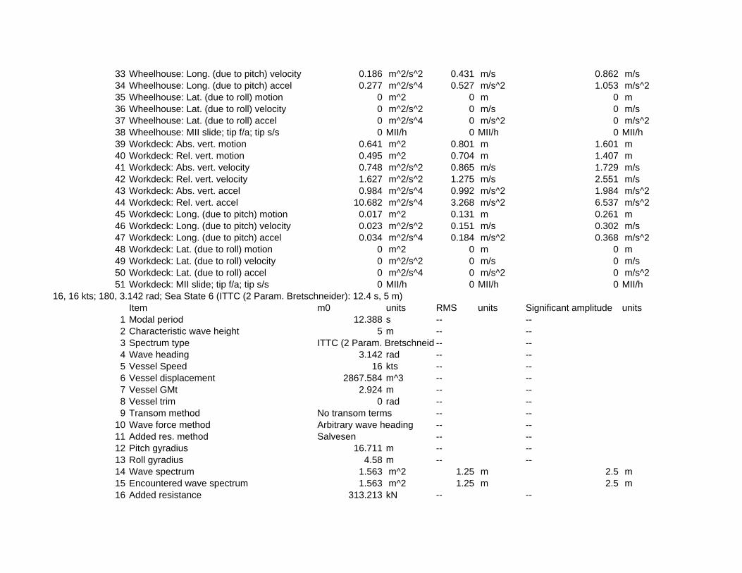
33 Wheelhouse: Long. (due to pitch) velocity 0.186 m^2/s^2 0.431 m/s 0.862 m/s34 Wheelhouse: Long. (due to pitch) accel 0.277 m^2/s^4 0.527 m/s^2 1.053 m/s^235 Wheelhouse: Lat. (due to roll) motion 0 m^2 0 m 0 m36 Wheelhouse: Lat. (due to roll) velocity 0 m^2/s^2 0 m/s 0 m/s37 Wheelhouse: Lat. (due to roll) accel 0 m^2/s^4 0 m/s^2 0 m/s^238 Wheelhouse: MII slide; tip f/a; tip s/s 0 MII/h 0 MII/h 0 MII/h39 Workdeck: Abs. vert. motion 0.641 m^2 0.801 m 1.601 m40 Workdeck: Rel. vert. motion 0.495 m^2 0.704 m 1.407 m41 Workdeck: Abs. vert. velocity 0.748 m^2/s^2 0.865 m/s 1.729 m/s42 Workdeck: Rel. vert. velocity 1.627 m^2/s^2 1.275 m/s 2.551 m/s43 Workdeck: Abs. vert. accel 0.984 m^2/s^4 0.992 m/s^2 1.984 m/s^244 Workdeck: Rel. vert. accel 10.682 m^2/s^4 3.268 m/s^2 6.537 m/s^245 Workdeck: Long. (due to pitch) motion 0.017 m^2 0.131 m 0.261 m46 Workdeck: Long. (due to pitch) velocity 0.023 m^2/s^2 0.151 m/s 0.302 m/s47 Workdeck: Long. (due to pitch) accel 0.034 m^2/s^4 0.184 m/s^2 0.368 m/s^248 Workdeck: Lat. (due to roll) motion 0 m^2 0 m 0 m49 Workdeck: Lat. (due to roll) velocity 0 m^2/s^2 0 m/s 0 m/s50 Workdeck: Lat. (due to roll) accel 0 m^2/s^4 0 m/s^2 0 m/s^251 Workdeck: MII slide; tip f/a; tip s/s 0 MII/h 0 MII/h 0 MII/h
16, 16 kts; 180, 3.142 rad; Sea State 6 (ITTC (2 Param. Bretschneider): 12.4 s, 5 m)Item m0 units RMS units Significant amplitude units
1 Modal period 12.388 s -- --2 Characteristic wave height 5 m -- --3 Spectrum type ITTC (2 Param. Bretschneid -- --4 Wave heading 3.142 rad -- --5 Vessel Speed 16 kts -- --6 Vessel displacement 2867.584 m^3 -- --7 Vessel GMt 2.924 m -- --8 Vessel trim 0 rad -- --9 Transom method No transom terms -- --
10 Wave force method Arbitrary wave heading -- --11 Added res. method Salvesen -- --12 Pitch gyradius 16.711 m -- --13 Roll gyradius 4.58 m -- --14 Wave spectrum 1.563 m^2 1.25 m 2.5 m15 Encountered wave spectrum 1.563 m^2 1.25 m 2.5 m16 Added resistance 313.213 kN -- --

17 Heave motion 1.918 m^2 1.385 m 2.77 m18 Roll motion 0 rad^2 0 rad 0 rad19 Pitch motion 0.00227 rad^2 0.04768 rad 0.09536 rad20 Heave velocity 1.666 m^2/s^2 1.291 m/s 2.581 m/s21 Roll velocity 0 (rad/s)^2 0 rad/s 0 rad/s22 Pitch velocity 0.00254 (rad/s)^2 0.05038 rad/s 0.10075 rad/s23 Heave acceleration 1.812 m^2/s^4 1.346 m/s^2 2.692 m/s^224 Roll acceleration 0 (rad/s/s)^2 0 rad/s/s 0 rad/s/s)25 Pitch acceleration 0.00338 (rad/s/s)^2 0.05812 rad/s/s 0.11623 rad/s/s)26 Wheelhouse: Abs. vert. motion 2.815 m^2 1.678 m 3.355 m27 Wheelhouse: Rel. vert. motion 1.388 m^2 1.178 m 2.356 m28 Wheelhouse: Abs. vert. velocity 2.621 m^2/s^2 1.619 m/s 3.238 m/s29 Wheelhouse: Rel. vert. velocity 2.809 m^2/s^2 1.676 m/s 3.352 m/s30 Wheelhouse: Abs. vert. accel 3.002 m^2/s^4 1.733 m/s^2 3.465 m/s^231 Wheelhouse: Rel. vert. accel 11.357 m^2/s^4 3.37 m/s^2 6.74 m/s^232 Wheelhouse: Long. (due to pitch) motion 0.274 m^2 0.523 m 1.046 m33 Wheelhouse: Long. (due to pitch) velocity 0.304 m^2/s^2 0.552 m/s 1.103 m/s34 Wheelhouse: Long. (due to pitch) accel 0.403 m^2/s^4 0.635 m/s^2 1.27 m/s^235 Wheelhouse: Lat. (due to roll) motion 0 m^2 0 m 0 m36 Wheelhouse: Lat. (due to roll) velocity 0 m^2/s^2 0 m/s 0 m/s37 Wheelhouse: Lat. (due to roll) accel 0 m^2/s^4 0 m/s^2 0 m/s^238 Wheelhouse: MII slide; tip f/a; tip s/s 0 MII/h 0 MII/h 0 MII/h39 Workdeck: Abs. vert. motion 1.752 m^2 1.324 m 2.647 m40 Workdeck: Rel. vert. motion 0.587 m^2 0.766 m 1.533 m41 Workdeck: Abs. vert. velocity 1.502 m^2/s^2 1.225 m/s 2.451 m/s42 Workdeck: Rel. vert. velocity 1.723 m^2/s^2 1.313 m/s 2.626 m/s43 Workdeck: Abs. vert. accel 1.633 m^2/s^4 1.278 m/s^2 2.556 m/s^244 Workdeck: Rel. vert. accel 10.23 m^2/s^4 3.198 m/s^2 6.397 m/s^245 Workdeck: Long. (due to pitch) motion 0.033 m^2 0.183 m 0.366 m46 Workdeck: Long. (due to pitch) velocity 0.037 m^2/s^2 0.193 m/s 0.386 m/s47 Workdeck: Long. (due to pitch) accel 0.049 m^2/s^4 0.222 m/s^2 0.444 m/s^248 Workdeck: Lat. (due to roll) motion 0 m^2 0 m 0 m49 Workdeck: Lat. (due to roll) velocity 0 m^2/s^2 0 m/s 0 m/s50 Workdeck: Lat. (due to roll) accel 0 m^2/s^4 0 m/s^2 0 m/s^251 Workdeck: MII slide; tip f/a; tip s/s 0 MII/h 0 MII/h 0 MII/h

69
Appendix M – Structural Calculations
Contents: Weights and Centers ..............................................................................................................M-1 Excel Calculations Spreadsheet .............................................................................................M-2 Net Load, Shear and Moment Diagram Full Load ................................................................M-3 Net Load, Shear and Moment Diagram 50% Fuel .................................................................M-4 Net Load, Shear and Moment Diagram 10% Fuel .................................................................M-5


N-1: Parameters
Figure N.1: Parameters used for structural Calculations
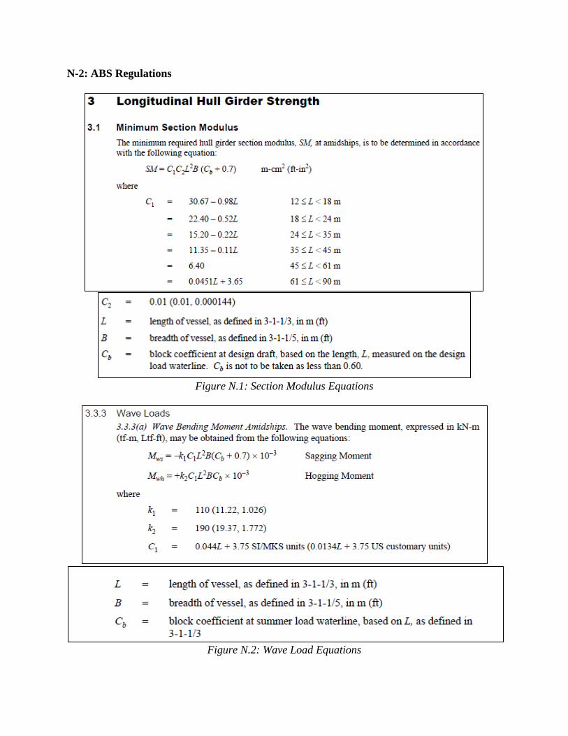
N-2: ABS Regulations
Figure N.1: Section Modulus Equations
Figure N.2: Wave Load Equations

Figure N.3: Required Section Modulus and Wave Load Calculations

Figure N.4: Required Section Modulus Calculations and Equations

Figure N.5: Side Shell Plating Equations
Figure N.6: Bottom Shell Plating Equations

Figure N.7: Side Shell and Bottom Shell Plating Calculations

Figure N.8: Side Shell End Plating Equations
Figure N.9: Forecastle and Poop Side Plating Equations
Figure N.10: Bow and Stern Thruster Tunnel Plating Equations

Figure N.11: Side Shell Plating at Ends, Forecastle/Poop Side Plating, and Tunnel Plating

Figure N.12 & N.13: Deck Plating Equations

Figure N.15 & N.16: Strength Deck Plating Equations
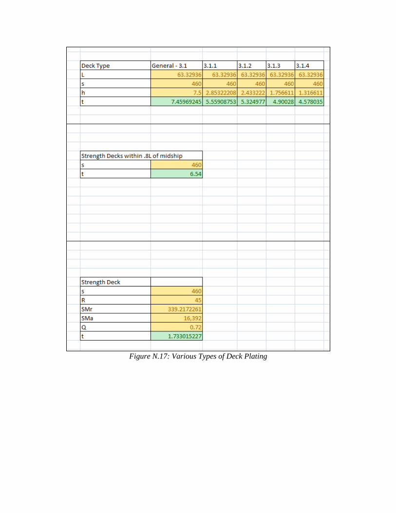
Figure N.17: Various Types of Deck Plating
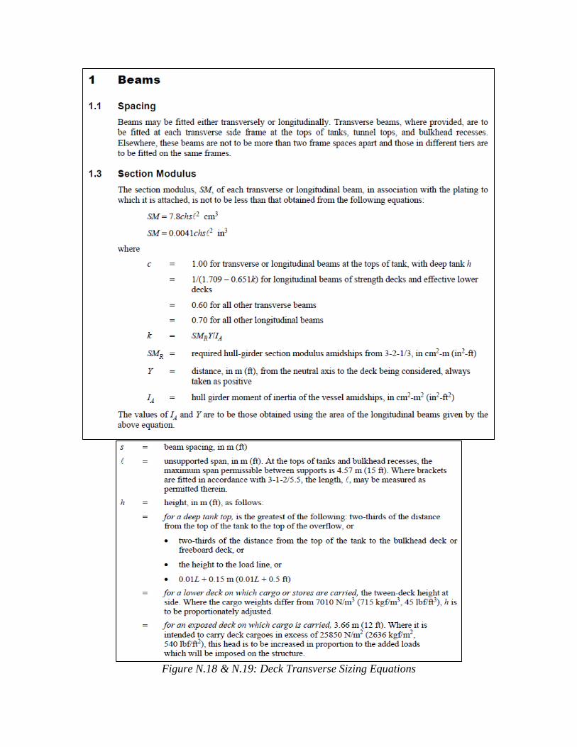
Figure N.18 & N.19: Deck Transverse Sizing Equations

Figure N.20 & N.21: Deck Transverse Sizing Equations
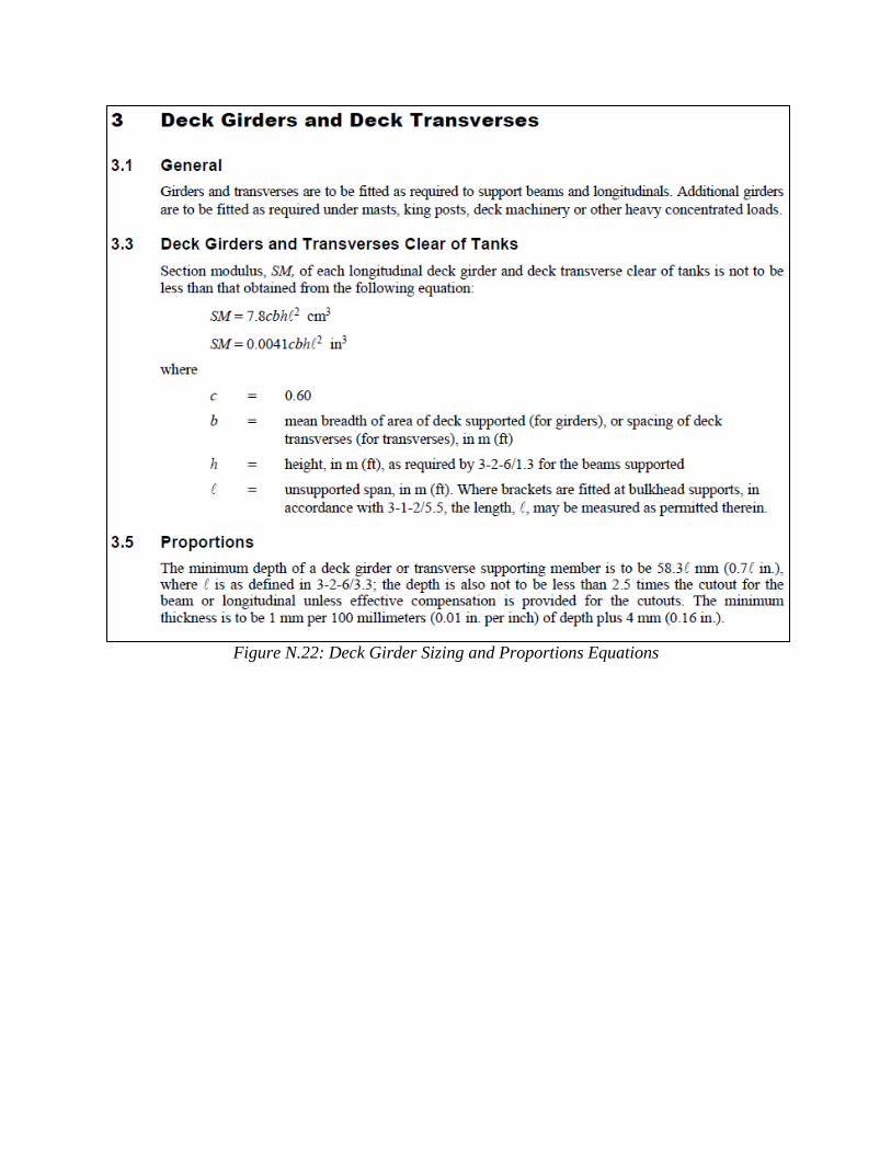
Figure N.22: Deck Girder Sizing and Proportions Equations

Figure N.23: Deck Frame and Girder Sizing Calculations

Figure N.24: Visual Definition of Proportions
Figure N.24: Bottom Transverse Equations and Calculations

Figure N.25: Collision Bulkhead Location Equations and Definitions

Figure N.25: Bulkhead Plating Equations

Figure N.26: Bulkhead Stiffener Sizing Equations
Figure N.27: Bulkhead Girder Sizing Equations

Figure N.28: Bulkhead Calculations

Figure N.29: Side Frame Equations

Figure N.30: Side Frame Calculations and Visual Definitions

Figure N.31: Deckhouse Stiffener Equations

Figure N.32 & N.33: Tween Deck Frame Equations and Visual Definitions
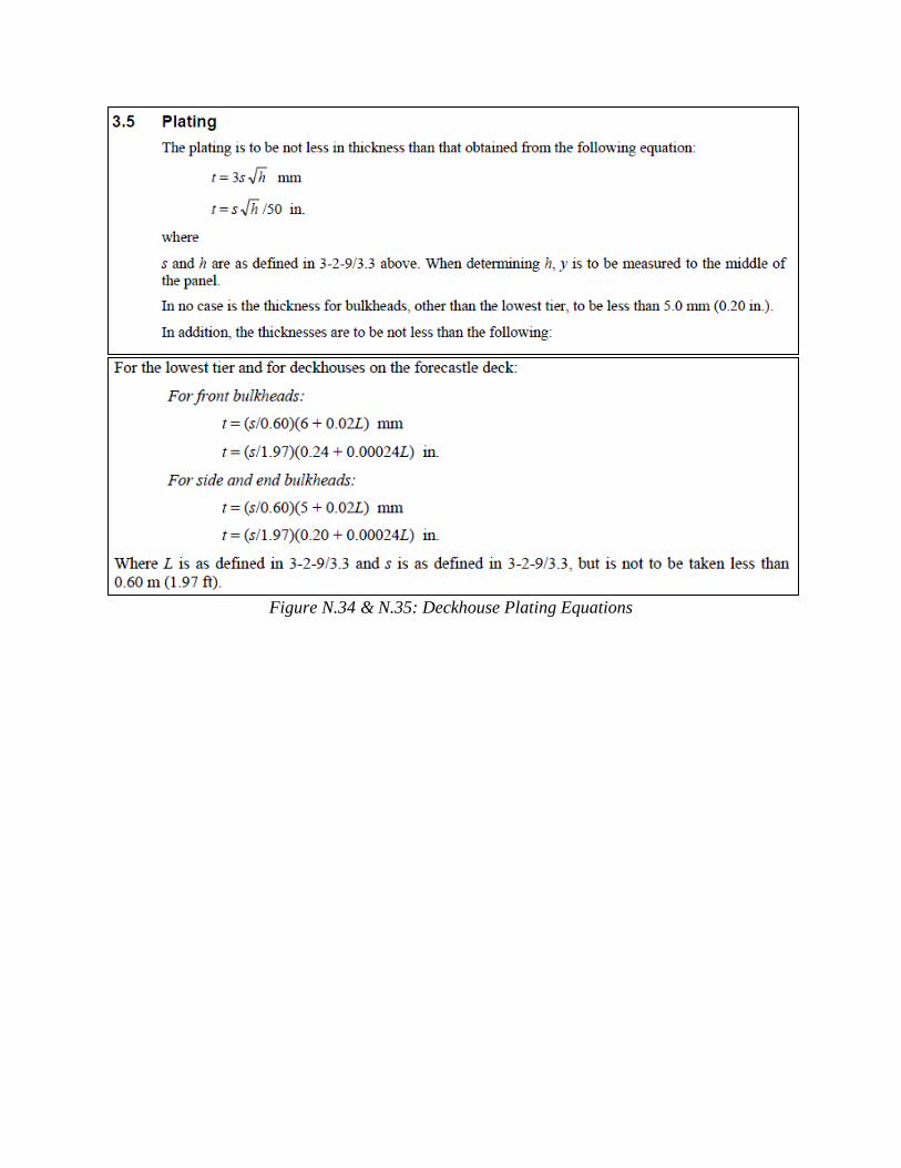
Figure N.34 & N.35: Deckhouse Plating Equations

Figure N.36: Tween Deck Frame and Deckhouse Plating Calculations

Figure N.37 & N.38: Deckhouse Plating Equations

Figure N.39 & N.40: Deckhouse Deck Beam Equations

Figure N.41: Deckhouse Deck Beam Calculations
Figure N.42: Deckhouse Deck Girder Equations

Figure N.43: Deckhouse Deck Girder Calculations

Figure N.44 & N.45: Deep Tank Plating Equations

Figure N.46: Deep Tank Stiffener Equations

Figure N.47: Deep Tank Stiffener Equations

N-3: Finnish Swedish Ice Class Regulations
Figure N.48: Height of Load Area
Figure N.49: Ice Pressure Equations

Figure N.49: Ice Pressure Parameters

Figure N.49: Ice Pressure Calculations
Figure N.50: Ice Belt Plate Thickness Equations
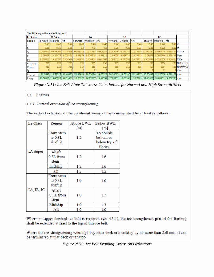
Figure N.51: Ice Belt Plate Thickness Calculations for Normal and High Strength Steel
Figure N.52: Ice Belt Framing Extension Definitions

Figure N.53: Ice Belt Framing Equations

Figure N.54: Ice Belt Framing Calculations

N-4: Midship Section Analysis
Figure N.55: Midship Section Analysis
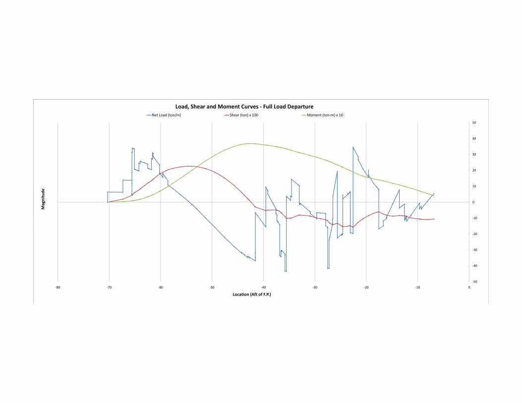
‐10
0
10
20
30
40
50
Magnitude
Load, Shear and Moment Curves ‐ Full Load Departure
Net Load (ton/m) Shear (ton) x 100 Moment (ton‐m) x 10
‐50
‐40
‐30
‐20
‐10
0
10
20
30
40
50
‐80 ‐70 ‐60 ‐50 ‐40 ‐30 ‐20 ‐10 0
Magnitude
Location (Aft of F.P.)
Load, Shear and Moment Curves ‐ Full Load Departure
Net Load (ton/m) Shear (ton) x 100 Moment (ton‐m) x 10

‐10
0
10
20
30
40
50
60
Magnitude
Load, Shear and Moment Curves ‐ 50% Fuel UsedNet Load (ton/m) Shear (ton) x 100 Moment (ton‐m) x 10
‐50
‐40
‐30
‐20
‐10
0
10
20
30
40
50
60
‐70 ‐60 ‐50 ‐40 ‐30 ‐20 ‐10 0
Magnitude
Location (Aft of F.P.)
Load, Shear and Moment Curves ‐ 50% Fuel UsedNet Load (ton/m) Shear (ton) x 100 Moment (ton‐m) x 10

‐10
0
10
20
30
40
50
60
Magnitude
Load, Shear and Moment Curves ‐ 90% Fuel used
Net Load (ton/m) Shear (ton) x 100 Moment (ton‐m) x 10
‐50
‐40
‐30
‐20
‐10
0
10
20
30
40
50
60
‐70 ‐60 ‐50 ‐40 ‐30 ‐20 ‐10 0
Magnitude
Location (Aft of F.P.)
Load, Shear and Moment Curves ‐ 90% Fuel used
Net Load (ton/m) Shear (ton) x 100 Moment (ton‐m) x 10


