Embed Size (px)
Citation preview
1
Seminar Report
“WIRELESS POWER SYSTEM TRANSMISSION FOR SOLAR POWERED
SATELLITE”
Submitted in Partial Fulfillment of the requirements
For the degree of
Bachelor of Technology
in
Instrumentation &Control Engineering
Department of Instrumentation and Control Engineering
Amity School of Engineering and Technology
GGS Indraprastha University, New Delhi
Guide: Submitted By:
Mr. Vineet Dahiya Akanksha Trikha
ECE/ICE Department 0410403010
ICE – 4th
Year
2
CERTIFICATE
This is to certify that Mr. Akanksha Trikha student of B.Tech. (Instrumentation & Control), has
successfully completed his report entitled “WIRELESS POWER SYSTEM
TRANSMISSION FOR SOLAR POWERED SAELLITE” comprehends the authentic
work of his individual.
This report fulfills his Bachelor of Technology course requirement at 7th
semester at the Amity
School of Engineering and Technology, an institution affiliated to Guru Gobind Singh Indraprastha
University, New Delhi.
Date: Mr Vineet Dahiya
Place: New Delhi ECE/ICE Department
3
ACKNOWLEDGEMENT
First and foremost, I would like to thank Professor(Dr.) Rekha Agarwal, Director for the education.
Under her guidance that has provided strong fundamentals, positive competition and unmatched
learning experience.
I express my gratitude to our esteemed Ms. Pinki Nayak, (Head, Department of ECE & ICE) and
my guide Ms. Rachana Nagal. Their inspiration, motivation, suggestion and invaluable guidance
enabled me to study. Their careful observations and precise ideas were an immense help in refining
our content.
Akanksha Trikha
[04010403010]
4
ABSTRACT
Wireless Power transmission (WPT) is a useful and convenient technology that can be employed to
collect solar energy and concentrate on earth surface without the need for a wire connection called as
solar power satellites (SPS). Solar Power Satellite is an energy system which collects solar energy in
space and transmits it to the ground. It has been believed as a promising infrastructure to resolve
global environmental and energy problems for human beings. One of the most important
technologies for the SPS is the wireless power transmission from the geostationary orbit to the
ground. Microwave power transmission has been investigated and demonstrated for more than 40
years, but still requires further research regarding high-efficiency power conversion and high-
accuracy beam control for SPS application. The SPS is a gigantic satellite designed as an electric
power plant orbiting in the Geostationary Earth Orbit (GEO). It consists of mainly three segments;
solar energy collector to convert the solar energy into DC (direct current) electricity, DC-to-
microwave converter, and large antenna array to beam down the microwave power to the ground.
The first solar collector can be either photovoltaic cells or solar thermal turbine. The second DC-to-
microwave converter of the SPS can be either microwave tube system and/or semiconductor system.
It may be their combination. The third segment is a gigantic antenna array.

5
Table of Contents
Certificate 2
Acknowledgement 3
Abstract 4
1. Introduction 7
1.1 wireless power transmission 8
1.2 solar power satellites 9
1.2.1 Background 9
1.2.2 Basic concept 10
1.2.3 Importance 10
1.2.4 Advantages 10
1.3 Transmission
1.3.1 Microwave transmission 11
1.3.2 Laser transmission 11
2. system design-basic components 14
3. wireless powering of solar power satellite 16
6
4. Recent Technologies and trends of Wireless Power 19
Transmission Antennas and Transmitters
4.1 Antennas for Microwave Power Transmission 19
4.2 Recent Technologies for Transmitters 19
4.3 magnetron 20
5. Environmental issues 21
6. Advantages 24
Conclusion 25
Bibliography 26
7
LIST OF FIGURES
1. Chapter 1
Fig1: wireless power transmission block diagram
Fig2: solar power satellite-basic concept
2. chapter 2
Fig3: functioning of a rectenna
8
Chapter 1
INTRODUCTION
A Major problem Planet Earth is facing is provision of an adequate supply of clean energy. We face
three simultaneous challenges -- population growth, resource consumption, and environmental
degradation -- all converging particularly in the matter of sustainable energy supply. It is widely
agreed that our current energy practices will not provide for all the world's peoples in an adequate
way and still leave our Earth with a livable environment. Hence, a major task for the new century
will be to develop sustainable and environmentally friendly sources of energy. An approach to
exploiting solar power is to capture it in space and convey it to the Earth by wireless means. As with
terrestrial capture, Space Solar Power (SSP) provides a source that is virtually carbon-free and
sustainable. As will be described later, the power-collecting platforms would most likely operate in
geosynchronous orbit where they would be illuminated 24 hours a day (except for short eclipse
periods around the equinoxes). Thus, unlike systems for the terrestrial capture of solar, a space-based
system would not be limited by the vagaries of the day-night cycle. Furthermore, if the transmission
frequency is properly chosen, delivery of power can be carried out essentially independent of
weather conditions. Thus Space Solar Power could provide base load electricity.
9
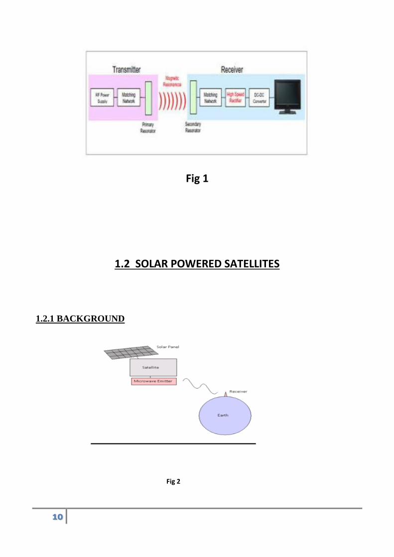
1.1 WIRELESS POWER TRANSMISSION (WPT)
BACKGROUND
The vision of achieving WPT on a global scale was proposed over 100 years ago when Nikola Tesla
first started experiments with WPT, culminating with the construction of a tower for WPT Tesla's
objective was to develop the technology for transmitting electricity to anywhere in the world without
wires. Wireless communication is the transmission of the energy over a distance without, the usage
wires or cables, where in distances involved may be short or long. Wireless operations permits
services, such as long-range communications, that are merely unfeasible using wires. Wireless
energy transfer or wireless power transmission is the transmittance of electrical energy from a power
source to an electrical load without interconnecting wires. Wireless transmission is useful in cases
where interconnecting wires are inconvenient, hazardous, or impossible. The problem of wireless
power transmission differs from that of wireless telecommunications, such as radio. In the latter, the
proportion of energy received becomes critical only if it is too low for the signal to be distinguished
from the background noise. With wireless power, efficiency is the more significant parameter. A
large part of the energy sent out by the generating plant must arrive at the receiver or receivers to
make the system economical. The most common form of wireless power transmission is carried out
using direct induction followed by resonant magnetic induction. Other methods under consideration
include electromagnetic radiation in the form of microwaves or laser beam technology.
Two types of WPT:
1) Ground based power transmission
2) Space based power transmission
10
Fig 1
1.2 SOLAR POWERED SATELLITES
1.2.1 BACKGROUND
Fig 2
11
Since 1967, Solar Power Satellites (SPS) have proposed to collect solar energy in space and
beam it down to the Earth. With the energy crisis of the early 1970's, SPS was seriously
considered as an alternative to producing electric power from fossil fuels.
1.2.2 SOLAR POWER SATELLITE: BASIC CONCEPT
Basic idea of SPS is to collect the solar energy in orbit and send it to ground by microwave, laser
beam or some other way. The concept of the Solar Power Satellite energy system is to place giant
satellites, covered with vast arrays of solar cells, in geosynchronous orbit 22,300 miles above the
Earth's equator. Each satellite will be illuminated by sunlight 24 hours a day for most of the year.
Because of the 23" tilt of the Earth’s axis, the satellites pass either above or below the Earth’s
shadow. It is only during the equinox period in the spring and fall that they will pass through the
shadow. They will be shadowed for less than 1% of the time during the year.The solar cells will
convert sunlight to electricity, which will then be changed to radio-frequency energy by a
transmitting antenna on the satellite and beamed to a receiver site on Earth. It will be reconverted to
electricity by the receiving antenna, and the power would then be routed into our normal electric
distribution network for use here on the Earth. Figure 1 illustrates the concept. The great advantage
of placing the solar cells in space instead of on the ground is that the energy is available 24 hours a
day, and the total solar energy available to the satellite is between four and five times more than is
available anywhere on Earth and 15 times more than the average location. Testing has demonstrated
that wireless energy transmission to the Earth can be accomplished at very high efficiencies. Tests
have also shown that the energy density in the radio-frequency beam can be limited to safe levels for
all life forms. The concept is simple; the technology exists.
1.2.3 Importance:
Realization of external supplying power to satellite moving on its orbit can lead to weight reduction
and miniaturization of power
system. It can also reduce difficulties in launching satellite like launching cost. Standardization of
wireless power transmission module has the effects of being on market faster and improvement of
usability’s effects. Thus, building of the Flexibility Power Supply Network which uses wireless
power transmission technology expands potential of nano-satellites in space
1.2.4 Advantages
12
There are several advantages to SPS. Solar radiation can be more efficiently collected in space,
where it is roughly three times stronger than on the surface of the Earth and it can be collected 24
hours per day (since there are no clouds or night in high Earth orbit). SPS does not use up valuable
surface area on the Earth and can be beamed to areas with the highest demand at any particular time.
Most of these systems would utilize photovoltaic (PV) cells similar to those on Earth-based systems
Others would utilize reflectors and mechanical collectors similar to those used in special large-scale
solar facilities in France and the California desert (Barstow). Some PV systems would also use
reflective concentrators. Most of these systems collect solar energy in space and transmit it via a
microwave energy beam to an Earth-based rectenna which converts the beam into electricity for use
on Earth. Microwave beams have a fairly low wavelength (lower than visible light) and do not
appear to pose any danger to the Earth's atmosphere.
energy in space and transmit it via a microwave energy beam to an Earth-based rectenna which
converts the beam into electricity for use on Earth.
1.3 TRANSMISSION
Various methods of wireless energy transfer are being studied that may allow us to
transmit large amounts of power over long distances without the need for a
conducting connection. Additionally, wireless transmission presents the possibility of
sending and receiving power from space, which can have useful applications.
Microwave Power Transmission
One of the earliest demonstrations of wireless energy transfer was the use of microwave radiation to
power a small helicopter in 1964. This experiment contained the basic elements of microwave power
transmission: a source of electromagnetic radiation, and a microwave receiver with a DC rectifier to
transform the microwave energy into DC electrical power. Since then, efforts have been made to
increase the efficiency, power, and range of microwave transmission. The highest microwave-to-DC
electrical energy conversion achieved was 84% in an experiment in 1975. However, more practical
systems with higher power output have had lower efficiencies. A team in Japan built a system
consisting of a set of solar panels attached to a microwave transmitter, and a receiver which converts
13
microwaves to a DC voltage. The transmitter was designed to track the receiver and automatically
direct its microwave output toward the receiver. This system was able to achieve a conversion
efficiency of over 75% with an output of 300 watts. A next desired goal would be to achieve high
efficiency energy transfer over long distances.
Laser Transmission
The laser method of energy transfer involves shining a laser beam onto a photovoltaic receiver. This
requires the ability to precisely track the position of the receiver relative to the laser transmitter. The
advantage of a laser is that its monochromaticity allows better control of the beam over long ranges,
as well as a possibility to tune the photovoltaic receiver to the laser beam. Recent experiments using
commercially obtainable laser sources have generated over 7.2 watts of photovoltaic output from a
70 watt laser beam (from which only 25 watts reached the receiver). This corresponds to a power
density of 13.6 watts per square centimeter of receiver area, as well as a 28% optical-to-electrical
conversion efficiency, which is promising for real applications if the experimental result can be
scaled to larger systems.
14
CHAPTER 2
SYSTEM DESIGN -BASIC COMPONENTS
SPACETENNA: (THE ANTENNA ON SATELLITE)
Spacetenna is a triangular prism with a length of 800 m and sides of 100 m. The main axis lies in the
north-south direction, perpendicular to the direction of orbital motion. The transmitting antenna on
the horizontal under-surface faces the Earth, and the other two sides of the prism carry solar arrays. The faces of the prism are embedded with photovoltaic cells. These Photovoltaic cells would convert
sunlight into electrical current, which would, in turn, power an onboard microwave generator. The
Microwave thus produced Travels through Atmosphere & is collected by RECTENNAS on Earth.
The Spacetenna has a square shape whose dimension is 132 meters by 132 meters and which is
regularly filled with 1936 segments of sub array. The sub array is considered to be a unit of phase
control and also a square shape whose edges are 3 meters. It contains 1320 units of cavity-backed
slot antenna element and DC-RF circuit. Therefore, there will be about 2.6 million antenna elements
in the spacetenna. The spacetenna is composed of pilot signal receiving antennas followed by
detectors finding out the location of the rectenna on the earth, power transmission antenna elements
and phase control systems. Moreover, the pilot signal frequency and a frequency for the energy
transmission are different from each other. Using two kinds of frequency for the power transmission
and the pilot signal prevents each other from interfering and makes it possible to find out the
accurate direction of a specified rectenna.
RECTENNNA :(RECTIFYING ANTENNA)
A Rectenna can be considered as a base station for a geo-stationary satellite. Microwaves of 2.45
GHz frequency are used to transmit power from the satellite to the rectenna. It consists of a mesh of
an array of dipole antennas connected to diodes to convert the radio frequency energy to DC voltage,
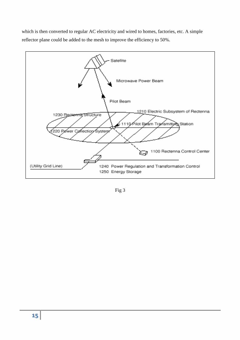
15
which is then converted to regular AC electricity and wired to homes, factories, etc. A simple
reflector plane could be added to the mesh to improve the efficiency to 50%.
Fig 3
16
Chapter 3
Wireless powering of solar power satellite
Solar power from the satellite is sent to Earth using a microwave transmitter. This transmission is
transmitted to the relevant position via an antenna. The transmission is transmitted through space
and atmosphere and received on earth by an antenna called the rectenna. Recent developments
suggest using laser by using recently developed solid state lasers allow efficient transfer of
power. A range of 10% to 20% efficiency within a few years can be attained, but further
experimentation still required taking into consideration the possible hazards that it could cause to
the eyes. In comparison to laser transmission microwave transmission is more developed, has
high efficiency up to 85%, beams is far below the lethal levels of concentration even for a
prolonged exposure. The microwave transmission designed has the power level well below the
international safety standard (Frequency 2.45 GHz microwave beam). The electric current
generated from the photovoltaic cells is passed through a magnetron which converts the electric
current to electromagnetic waves. This electromagnetic wave is passed through a waveguide
which shapes the characteristics of the electromagnetic wave.
Effectiveness of Wireless Power Transmission (WPT) depends on many parameters. Only a part
of WPT system is discussed below, which includes radiating and receiving antennas and the
environment between them. The wave beam is expanded proportionately to the propagation
distance and a flow power density is increased inversely proportional to the square of this
distance. However the WPT has some peculiarities, which will be mentioned here. WPT systems
require transmitting almost whole power that is radiated by the transmitting side. So, the useful
result is the power quantity at the receiving antenna, but not the value of field amplitude as it is
usually required. Efficiency of WPT systems is the ratio of energy flow, which is intercepted by
receiving antenna to the whole radiating energy.
Field distribution on the receiving antenna usually is uniform because its size is small
comparatively to the width of the beam. For WPT systems this distribution IS NOT uniform. It
has a taper form and it depends on the field distribution on the transmitting antenna.
17
For increasing of the energy concentration on the receiving antenna the phase distribution on the
radiating antenna has usually a spherical form with the center in the point on crossing of the
receiving plate and the radiating axis. Radiating antenna of the WPT systems usually has a taper
distribution of the field. This distribution allows to increase the efficiency and to decrease the
field out of the receiving antenna.
The efficiency of energy transmission is expressed by the functional 2. To increase the field
distribution on radiating aperture is made as a tapered distribution. High value of is supposed to
be in the majority of known projects of the WPT systems.
However, the effectiveness of the WPT system is defined not only by the value of . It is also
determined by the rectangularity of the field distribution on the radiating aperture, the rectangular
distribution factor in the theory of antennas is usually called the surface utilization factor. The
meaning of these two parameters and is discrepant because to increase 2 it is necessary to have
the field falling down to edges, but to increase it is necessary to have a uniform field.
To increase the effectiveness of WPT system it is necessary to increase the product 2, though the
requirements for each of both multipliers are opposite. This product is named a generalize
criterion! It is possible to find the way out of this contradiction if the antenna is discontinuous
(discrete) one. Let us produce the field distribution in the radiating discrete antenna falling to its
edges not by means of creation of non-uniform distribution of the field but with the help of
irregular situation of identical sub apertures, each of them having the uniform field distribution. It
is supposed that the number of these apertures is sufficiently high in order to admit the
approximation of the integral optimum monotonous Gauss distribution by means of step
function. The places of sub aperture disposition can be found by the differentiation of this step
function. Discrete distribution of sub apertures presents non-equadistant antennaarray consisting
of the similar elements. Such optimization is optimal in Chebyshevâ„¢s sense since the
maximum error tends to zero while the number of sub apertures is tended to infinity. So the field
in the place of observerâ„¢s disposition would be similar to step and the monotonous signal
source. The falling to the edge field distribution is typical for the WPT problems. For the
discrete-step distributions that means the concentration of sub apertures in the center and their
gradual discharge on the edges. Thus all sub apertures are similar and have the uniform
distribution of the field with the equal amplitude, which may reach the maximum admissible
value.
The dismemberment of continuous apertures and slight moving of them apart in the space when
all of apertures are equal and uniformly feed increases their effectiveness (the generalized
18
criterion is increased). The generalized criterion determines the quality of the WPT Systems
better than usual criterion. The optimal distribution form may be reached for the large radiating
apertures where dismemberment at many parts is easily realized by disposition of sub aperture
clots in places, which correspond to high field intensity (first of all it concerns the center of the
radiator) and relieving sub aperture density at edges of antenna. This construction allows to
approach to unit the value both of coefficients 2 and As a result the effectiveness of the WPT
system will be essentially increased. For receiving these transmitted waves rectennas are set up at
the Earth. An antenna comprising a mesh of dipoles and diodes for absorbing microwave energy
from a transmitter and converting it into electric power. Microwaves are received with about
85% efficiency and 95% of the beam will fall on the rectenna but the rectenna is around 5km
across (3.1 miles). Currently there are two different design types being looked at- Wire mesh
reflector and Magic carpet. Wire mesh reflector type rectennas are built on a rigid frame above
the ground and are visually transparent so that it would not interfere with plant life whereas in the
magic carpet type material pegged to the ground.
19
Chapter 4
Recent Technologies and trends of Wireless Power Transmission
Antennas and Transmitters:
Antennas for Microwave Power Transmission
All antennas can be applied for both the MPT system and communication system, for example, Yagi-
Uda antenna, horn antenna, parabolic antenna, microstrip antenna, phased array antenna or any other
type of antenna. To fixed target of the MPT system, we usually select a large parabolic antenna, for
example, in MPT demonstration in 1975 at the Venus Site of JPL Goldstone Facility and in ground-
to-ground MPT experiment in 1994-95 in Japan (See Fig.2.2 and Fig.2.6). In the fuel-free airship
light experiment with MPT in 1995 in Japan, they changed a direction of the parabolic antenna to
chase the moving airship.
Recent Technologies for Transmitters
However, we have to use a phased array antenna for the MPT from/to moving transmitter/receiver
which include the SPS because we hav The technology employed for the generation of microwave
radiation is an extremely important Phased Array Used in Japanese Field MPT Experiment ( for
MILAX in 1992, for SPRITZ in 2000) e to control a microwave beam direction accurately and
speedy. The phased array is a directive antenna which generate a beam form whose shape
anddirection by the relative phases and amplitudes of the waves at the individual antenna elements. It
is possible to steer the direction of the microwave beam. The antenna elements might be dipoles, slot
antennas, or any other type of antenna, even parabolic antennas.In some MPT experiments in Japan,
20
the phased array antenna was adopted to steer a direction of the microwave beam. All SPS is
designed with the phased array antenna. We consider the phased array antenna for all following MPT
system.
Magnetron
Magnetron is a crossed field tube in which E B r r × forces electrons emitted from the cathode to
take cyclonical path to the anode. The magnetron is self-oscillatory device in which the anode
contains a resonant RF structure. The magnetron has long history from invention by A. W. Hull in
1921. The practical and efficient magnetron tube gathered world interest only after K. Okabe
Average RF output power versus frequency for various electronic devices and semiconductors
proposed the divided anode-type magnetron The magnetrons main were advanced and manufactured
for the microwave ovens. As a result, the magnetron of 500 – 1,000 W is widely used in microwave
ovens in 2.45 GHz, and is a relatively inexpensive oscillator (below $5). There is a net global
capacity of 45.5GW/year for all magnetrons used in microwave ovens whose production is 50– 55
millions. A history of the magnetron is a history of a microwave oven. The first microwave oven
with a magnetron sold shortly in U. S. A. after the World War II ended for more than $2,000, the
equivalent of about $20,000 today. In 1960’s, Japan played a important role to reduce the cost of the
microwave oven. Compared that American tube’s cost was $300 and they planned to sell for $500 in
1960’s, Japanese tube cost was less than $25. In 1970, U.S. manufacturers sold 40,000 ovens at $300
to $400 apiece, but by 1971 the Japanese had begun exporting low-cost models priced $100 to $200
less. Sales increased rapidly over the next 15 years, rising to a million by 1975 and 10 million by
1985, nearly all of them Japanese[5]. But history repeats itself. Instead of Japanese microwave oven,
Korean and Chinese more reduce the cost of the microwave oven now. Therefore, the magnetron is
suitable device for the MPT because of high efficiency and low cost unsuitable device because of its
unstable frequency and uncontrollable phase. If we do not make a phased array to control beam
direction electrically, the magnetron can be applied for the MPT system. However, the cooker-type
magnetron itself cannot be applied for the phased array-type MPT because it is only a generator and
we cannot control/stabilize the phase and the amplitude. The cooker-type magnetron was considered
as noisy device. It is however confirmed that spurious emissions from the cooker-type magnetron
with a stable DC power supply is low enough and this can be applied to the MPT system[6]. Peak

21
levels of higher harmonics are below -60 dBc and other spurious is below -100 dBc..
22
Chapter 5
ENVIRONMENTAL ISSUES
Interferences to Existent Wireless System
There is no allowed frequency band for the MPT ,therefore, we used the ISM band. The bandwidth
of the microwave for the MPT do not need wideband and it is enough quite narrow since an
essentially monochromatic wave is used without modulation because we use only carrier of the
microwave as energy. Power density for the MPT is a few orders higher than that for the wireless
communication. We have to consider and dissolve interferences between the MPT to the wireless
communication systems. One calculation of the interferences between the MPT of the SPS, mainly
2.45 GHz, to the wireless communication systems was done in Japan[20]. If the harmonics of the
MPT frequencies are, however regulated by the ITU (International Telecommunication Union)
power flux density (PFD) limits, some modulation might be necessary. Carrier noises, harmonics,
and spurious emissions of the MPT signal should be quite small to avoid interference to other radio
services in operation around the world. Grating lobes and sidelobes of the MPT beam should be low
enough in order to make the affect region as small as possible. Also, grating lobes should be
mitigated because they are a direct loss of transmitter power. The other interference assessment on
2.45 GHz and 5.8 GHz MPT of the SPS was published inJapan.
Safety on Ground
One of the characteristics of the MPT is to use more intense microwave than that in wireless
communication systems. Therefore, we have to consider MPT safety for human. In recent years there
24have been considerable discussions and concerns about the possible effect for human health by RF
and MW radiation. Especially, there have been many research and discussions about effects at 50/60
Hz and over GHz (microwave). These two effects are different. There is long history concerning the
safety of the microwave[24]. Contemporary RF/microwave standards are based on the results of
critical evaluations and interpretations of the relevant scientific literature. The SAR (specific
23
absorption rate) threshold for the most sensitive effect considered potentially harmful to humans,
regardless of the nature of the interaction mechanism, is used as the basis of the standard. The SAR
is only heating problem. The scientific research results have indicated that the microwave effect to
human health is only heating problem. This is different from the EMF research. Famous guideline,
the ICNIRP (International Commission on Non-Ionizing Radiation Protection) guidelines, are 50 or
10 W/m2 for occupationally exposed vs. the general public, at either frequency[25]. The
corresponding limits for IEEE standards for maximum permissible human exposure to microwave
radiation, at 2.45 or 5.8 GHz, are 81.6 or 100 W/mas averaged over six min, and 16.3 or 38.7 W/m2
as averaged over 30 min, respectively, for controlled and uncontrolled environments[26]. The
controlled and uncontrolled situations are distinguished by whether the exposure takes place with or
without knowledge of the exposed individual, and is normally interpreted to mean individuals who
are occupationally exposed to the microwave radiation, as contrasted with the general public. In
future MPT system, we have to keep the safety guideline outside of a rectenna site. Inside the
rectenna site, there remains discussion concerning the keep out area, controlled or uncontrolled area.
Interaction with Atmosphere
In general, effect of atmosphere to microwave is quite small. There are absorption and scatter by air,
rain, and irregularity of air refraction ratio. In 2.45 GHz and 5.8 GHz, the absorption by water vapor
and oxygen dominate the effect in the air. Especially, it is enough to consider only absorption by the
oxygen in the microwave frequency. It is approximately 0.007 dB/km[27]. In the SPS case, the
amount of total absorption through the air from space is approximately 0.035 dB[28]. When
elevation is 47 degree in the middle latitude, for example, in Japan, the total absorption is
approximately 0.05 dB.
24
Chapter 6
Advantages
It is Unaffected by day-night cycle, weather or seasons. Optimized advances may enable 21 hour
power supply per day .This is an eco-friendly, renewable and maintenance free energy resource
unlike the conventional fuels .As the equipment is positioned in space, it is occupies no land area
and remains unaffected by harsh weather conditions. Rectennas can share land with farms. The
spacetenna could direct energy to any rectenna on earth within the range of its steering angle,
which could satisfy the energy requirements of all the equatorial countries. Waste heat is re-
radiated back into space, instead of warming the biosphere.
25
CONCLUSION
Electrical energy can be economically transmitted without wires to any terrestrial distance. The
economic transmission of power without wires is of crucial importance to man. It will enable him to
dispense with innumerable causes of sinful waste. This technology opened up the possibility of
constructing power stations on the moon. These power stations will be capable of transmitting power
to earth using microwave energy. Such microwave energy would then be converted into electricity
using a vast array of rectenna receivers on the earth. Nevertheless with all the challenges that face
wide-scale deployment of this new technology wireless power transmission for solar power satellite
is still considered as a next-generation power transmission system.
26
BIBLIOGRAPHY
• “Wireless Power Transmission Technologies for Solar Power Satellite” Susumu Sasaki, Koji
Tanaka. International communication conference IEEE 2011.
• S.Sasaki, K.Tanaka and Advanced Mission Research Group, “SSPS Technologies
Demonstration in Space” , IAC-10.C3.4.1, 61st International Astronautical Congress, Prague,
Sep.-Oct. 2010.
• “Wireless Power Transmission – A Next Generation Power Transmission System”. S. Sheik
Mohammed, K. Ramasamy, T. Shanmuganantham. IEEE 2010 International Journal of
Computer Applications.
• P.E.Glaser, “Power from the Sun: Its Future”, Science, vol.162,pp.867-886, 1968.
• Yamamoto, S., N. Shinohara, and H. Matsumoto, “Study of Phase Array with Phase
Controlled Magnetrons (in Japanese)”, Proc. of IEICE, 2003, p.C-2-105