Embed Size (px)
Citation preview

1
SEMI-ACTIVE CONTROL OF SMART BASE ISOLATION SYSTEM
WITH MAGNETORHOLOGICAL DAMPER
Nikoo KHANMOHAMMADI HAZAVEH1, Stefano2 PAMPANIN
2, J Geoffrey CHASE
3
Geoffrey W RODGERS4.
ABSTRACT
One of the most widely implemented and accepted seismic protection systems is base isolation.
However, because optimal design of base isolation depends on the intensity of the design level
earthquake that is considered, the reduction of the seismic response is not optimal for a wide range of
input ground motion intensities. In this paper, a smart base isolation system is proposed by combining
traditional base isolation systems with magnetorheological (MR) dampers to achieve specified control
target performance. This study employs four algorithms: discrete wavelet transform (DWT), particle
swarm optimization (PSO), linear quadratic regulator LQR, and clipped-optimal control algorithm.
DWT is used to obtain the local energy distribution of the motivation over the frequency bands. PSO
is used to determine the gain matrices through the online update of the weighting matrices used in the
LQR controller while eliminating the trial and error. A clipped-optimal control algorithm is used in
order for the MR damper control force to approach the desired optimal force that is obtained from the
modified LQR. Moreover, Bouc-Wen phenomenological model is utilized to investigate the nonlinear
behaviour of the MR dampers. The advantage of the proposed control algorithm is the improvement of
the performance of a conventional base isolation system via a semi-active MR damper that can change
damping coefficient continuously. The design and control method is applied to a base-isolated two-
degrees-of-freedom system implementing magnetorheological dampers subject to several historical
near-fault ground motions. The results indicate that the proposed method is more effective at reducing
the displacement response of the base isolation in real time when compared to a traditional base
isolation systems or a base isolation system with an MR damper that employed a classical LQR
control method.
INTRODUCTION
Base isolation is arguably one of the most effective solutions to protect structures subject to
earthquake excitations.(Skinner et al.1993; Naeim and Kelly 1999). In base isolation systems,
nonlinear devices such as lead-rubber, friction pendulum bearings, or high damping rubber bearings
are often used to restore force and obtaining adequate damping capacity. However, the vibration
reduction is not optimal for a wide range of external excitations as a result of the nonlinear behaviour
of these devices. The effectiveness of many passive base isolation systems has been questioned when
dealing with high-velocity, long period pulse or near-fault earthquakes, and when resonance occurred
1 Phd Candidate, University of Canterbury, Christchurch, New Zealand, [email protected]
2 Professor, University of Canterbury, Christchurch, New Zealand, [email protected]
3 Distinguish Professor, University of Canterbury, Christchurch, New Zealand, [email protected]
4 Lecturer, University of Canterbury, Christchurch, New Zealand, [email protected]

2
as per other passive systems. To address the shortcomings of passive control systems, semi active
control systems have been introduced in the past decades (Spencer and Sain., 1997). Semi-active
control has two main benefits over active and passive systems. First, it does not require much
energy/power to tune the characteristics of the damping devised and significantly reduce the seismic
response. Second, these systems can provide abroad range of control that a passive system, by nature,
cannot. Moreover, semi-active devices cannot in principle destabilize the structure because they do not
input additional energy to the system but simply absorb or store vibratory energy (Chase et al., 2006).
Because of this low dependence on external power sources and the removal of instability concerns,
semi–active systems may become an attractive solution for the improvement of reliability of low-
damage (e.g. rocking dissipative) and base isolation systems, regardless of the uncertainties of the
input ground motions. Among many other semi-active supplemental damping devices that could be
used within a structural system, magnetorheological (MR) dampers can achieve high-level adaptive
performance (Spencer et al 1997)(Figure 1). Mechanical simplicity, high dynamic range, low power
requirements, large force capacity, high stability, robustness, and reliability are among the desirable
features of MR dampers. MR dampers are capable of generating controllable damping forces by using
MR fluids. MR fluids are composed of magnetized tiny particles that are scattered in a mineral liquid
such as silicon oil. When a magnetic field is applied to this liquid, particle chains form in just a few
milliseconds, and the fluid becomes a semi-solid which exhibits plastic behaviour.
Figure 1: Large-scale semi-active damper schematic (Yang et al., 2002).
Because of the advantages of semi-active systems and the need for development of base
isolation systems that can be effective for a wide range of earthquakes, smart base isolation systems
that combine passive isolation systems with semi-active systems have been investigated by a number
of researchers, based on the implementation of electrorheological (ER) or magnetorheological (MR)
dampers (Yang et al. 1995, 1996; Makris 1997; Johnson et al. 1999; Symans and Kelly 1999; Yoshida
et al. 2002; Ramallo et al. 2000a,b ; Yang and Agrawal 2001). The effectiveness of semi-active base
isolation for a single span bridge model using MR dampers was experimentally shown by Nagarajaiah
et al. (2000). The MR damper requires lower voltage than the ER damper which is very attractive for
safety and practical reasons (Carlos et al 1996). This justifies why most practical applications use MR
fluids.
There are two types of dynamic models for the MR dampers: non-parametric models and
parametric models. Many non-parametric models have been used to control the dynamic behaviour of
MR dampers such as neural network-based models (Wang and Liao, 2005) and fuzzy logic-based
models (Kim et al., 2008). The Bingham model (Lee and Wereley, 2002), non-linear hysteretic bi-
viscous model (Kamath and Wereley, 1997), hyperbolic tangent model (Christenson et al., 2008) and
Bouc-Wen hysteresis model (Jansen and Dyke, 2000) are some of the parametric models that have
been used to model the behaviour of MR dampers.
To characterize the behaviour of MR fluid dampers, Spencer et al. (1997) introduced the simple
Bouc-Wen model. This model can predict the force-displacement and force-velocity behaviour well,
and the results obtained from this model are similar to the experimental data. However, the simple
Bouc-Wen model cannot capture the force roll-off when the acceleration and velocity have opposite

N.Khanmohammadi Hazaveh , S. Pampanin , J G. Chase, and G.W Rodgers 3
signs and the magnitude of the velocities is small. Therefore, to overcome this drawback, Spencer et
al. (1997) proposed a modified version of the Bouc-Wen model with higher level of accuracy.
Using an appropriate control algorithm is very important in order to achieve the desirable
control performance via modifying the magnitude of the applied magnetic field according to a defined
algorithm. Comprehensive studies have been done to determine the optimal actuator force for active-
control systems. The most widespread methods are LQR, LQG, H2, and H∞ (Chin, 2013). The LQR is
used widely by many researchers to determine the appropriate control force. However, classical
control algorithms such as LQR suffer from some inherent shortcomings for structural applications.
For instance, one of the major shortcomings of the LQR algorithm for application to forced vibration
control of structures is its inability to explicitly account for the excitation. To simulate realistic
circumstances, the excitation must be known prior to determining the optimal control force to achieve
more reliable solutions. The effect of the specific earthquakes has been accounted for in a few studies
(Wu et al., 1998, Wu et al., 1994). For example Panarillo et al. (1997) introduced a method based on
updating weighting matrices from a database of earthquakes. Nonetheless, in these studies, offline
databases were still required. Basu et al. (2008) and Amini et al. (2013) proposed a wavelet-based
adaptive LQR and wavelet PSO-based-LQR (WPSOB-LQR) control to design the controller by
updating the weighting matrices, respectively. These methods determine the time-varying gain
matrices by updating the weighting matrices online, through the Ricatti equation (Basu et al 2008).
Therefore, these methods do not need prior information on the external excitation, hence eliminating
the need for an offline database.
In this article the feasibility and efficiency of a smart base isolation with MR dampers modelled
using a modified Bouc-Wen model is discussed. Moreover, a Clipped-optimal control algorithm based
on WPSOB-LQR is employed to find the optimal control force of MR dampers. The application of
proposed approach to a number of pulse-like near ground motions is presented, and the efficiency of
adding MR dampers in base isolation is evaluated.
MODIFIED BOUC-WEN MODEL
The schematic of the MR damper mechanical model for the modified Bouc-Wen model is
shown in Figure 2b.In this case, the nonlinear force of MR damper is calculated by (Yang et al., 2002):
(1)
Where α is Bouc-Wen model parameter related to the MR material yield stress and z is
hysteretic displacement of model given by:
(2)
is defined as:
(3)
Where c0 is the viscous damping parameter at high velocities; c1 is the viscous damping
parameter for the force roll-off at low velocities; k0 controls the stiffness at large velocities; k1
represents the accumulator stiffness; x0 is the initial displacement of the spring stiffness k0; ɣ, β and A
are adjustable shape parameters of the hysteresis loops, i.e., the linearity in the unloading and the

4
transition between pre-yielding and post-yielding regions.
Figure 2: Mechanical model for MR damper: (a) Simple Bouc-Wen model, (b) modified Bouc-Wen model.
Optimal performance for MR damper control systems is gained by varying the applied voltage
to the current driver according to the measured feedback at any moment. Thus, to determine a
comprehensive model that is valid for fluctuating magnetic fields, the parameters α, c0, c1 and k0 in
Equations 1-3 are defined as a linear function of the efficient voltage u as given in Equation 4 to
Equation 7.
(4)
(5)
(6)
(7)
To accommodate the dynamics involved in the MR fluid reaching rheological equilibrium, the
following first order filter is employed to calculate efficient voltage, u.
(8)
Where, v and u are input and output voltages of a first-order filter, respectively; and ɳ is the
time constant of the first-order filter. Figure 3 illustrates the comparison between the response of this
model and the experimental results for a 3kN MR damper in a real control condition that a damper
would face during the control time. It is obvious that this model is capable of predicting MR damper
nonlinear behaviour very well.
Figure 3: Predicted response by the Bouc-Wen phenomenological model in comparison with the
experimental data for a 3kN MR damper in a control simulation test (Spencer et al., 1997).
N.Khanmohammadi Hazaveh , S. Pampanin , J G. Chase, and G.W Rodgers 5
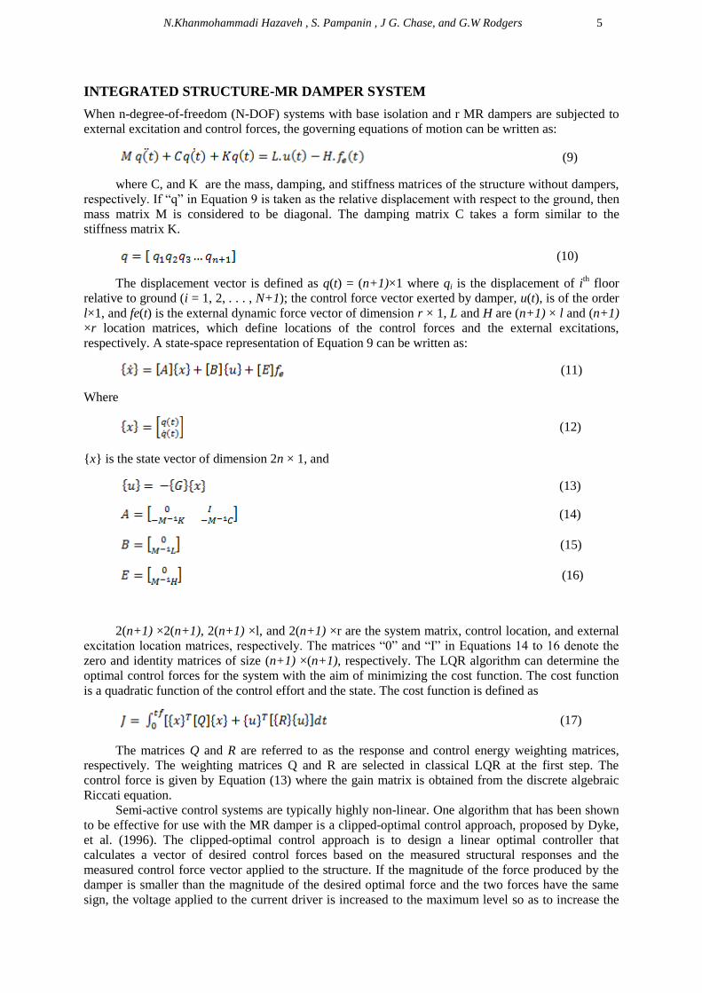
INTEGRATED STRUCTURE-MR DAMPER SYSTEM
When n-degree-of-freedom (N-DOF) systems with base isolation and r MR dampers are subjected to
external excitation and control forces, the governing equations of motion can be written as:
(9)
where C, and K are the mass, damping, and stiffness matrices of the structure without dampers,
respectively. If “q” in Equation 9 is taken as the relative displacement with respect to the ground, then
mass matrix M is considered to be diagonal. The damping matrix C takes a form similar to the
stiffness matrix K.
(10)
The displacement vector is defined as q(t) = (n+1)×1 where qi is the displacement of ith floor
relative to ground (i = 1, 2, . . . , N+1); the control force vector exerted by damper, u(t), is of the order
l×1, and fe(t) is the external dynamic force vector of dimension r × 1, L and H are (n+1) × l and (n+1)
×r location matrices, which define locations of the control forces and the external excitations,
respectively. A state-space representation of Equation 9 can be written as:
(11)
Where
(12)
{x} is the state vector of dimension 2n × 1, and
(13)
(14)
(15)
(16)
2(n+1) ×2(n+1), 2(n+1) ×l, and 2(n+1) ×r are the system matrix, control location, and external
excitation location matrices, respectively. The matrices “0” and “I” in Equations 14 to 16 denote the
zero and identity matrices of size (n+1) ×(n+1), respectively. The LQR algorithm can determine the
optimal control forces for the system with the aim of minimizing the cost function. The cost function
is a quadratic function of the control effort and the state. The cost function is defined as
(17)
The matrices Q and R are referred to as the response and control energy weighting matrices,
respectively. The weighting matrices Q and R are selected in classical LQR at the first step. The
control force is given by Equation (13) where the gain matrix is obtained from the discrete algebraic
Riccati equation.
Semi-active control systems are typically highly non-linear. One algorithm that has been shown
to be effective for use with the MR damper is a clipped-optimal control approach, proposed by Dyke,
et al. (1996). The clipped-optimal control approach is to design a linear optimal controller that
calculates a vector of desired control forces based on the measured structural responses and the
measured control force vector applied to the structure. If the magnitude of the force produced by the
damper is smaller than the magnitude of the desired optimal force and the two forces have the same
sign, the voltage applied to the current driver is increased to the maximum level so as to increase the

6
force produced by the damper to match the desired control force. Otherwise, the commanded voltage
is set to zero. The algorithm for selecting the command signal for the MR damper is stated as
(18)
Although a variety of approaches may be used to design the optimal controller, LQR methods
are advocated because of their successful application in previous studies. The approach to optimal
control design is discussed in detail in (Mohajer Rahbari 2013).
Figure.4.Block diagram of semi-active control system
MODIFIED LQR METHOD
In this study, the real time discrete wavelet transform (DWT) controller is updated at regular time
steps from the initial time (t0) until the current time (tc) to achieve the local energy distribution of the
motivation over frequency bands. The time interval under consideration [t0, tc] is sub-divided into time
window bands. The time of ith window is [ti-1, ti] of which the signal can be decomposed into time
frequency bands by wavelet. Through a DWT with multi-resolution analysis (MRA) algorithm the
exact decomposition of signals over a time window bands are obtained in real time. The local energy
content at different frequency bands over the considered time window are given by the MRA.
Obviously, the frequency containing maximum energy is the domain frequency within that window.
When the domain frequency of each window is close to the natural frequency of the system, resonance
can occurred in the structure. This could lead to much higher than expected displacement response
(thus potential damage) in system. To mitigate the displacement response of the structural systems, a
high control force is needed that can be obtained with decreasing the value of the control energy
weighting matrix [R]. The advantage of this local optimal solution is that it has the ability to change
the value of the matrix R on specific frequencies in contrast to the classical LQR which is a global
optimal solution. To achieve this, the control energy weighting matrices are updated for every time
window by a scalar multiplier and can be defined as:
(19)
where δi is a scalar parameter used to scale the weighting matrix and is obtained via PSO
algorithm based on the time-frequency analysis of a response state. Hence, the scalar parameter of
gain matrix can be written as:

N.Khanmohammadi Hazaveh , S. Pampanin , J G. Chase, and G.W Rodgers 7
if the frequency of the excitation is close to the natural frequency of system,
otherwise.
The value of has been proposed as less than one when resonance occurs. This allows changing the
weighting matrices for different frequency bands.
PSO algorithm starts with a random population (swarm) of individuals (particles) in the search
space and works on the social behavior in the swarm. The position and the velocity of the ith particle in
the dimensional search space can be represented as Xi = [xi,1, xi,2, . . . , xi,d ] and Vi = [vi,1, vi,2, . . . , vi,d
], respectively. Each particle has its own best position (pbest) Pi = [pi,1, pi,2, . . . , pi,d ] corresponding to
the personal best objective value obtained so far at time t. The global best particle (gbest) is denoted by
Pg, which represents the best particle found so far at time t in the entire swarm. The new velocity of
each particle is calculated as follows:
(20)
where j = 1, 2, . . . , d; c1 and c2 are acceleration coefficients; w is the inertia factor; and r1 and r2 are
two independent random numbers uniformly distributed in the range of [0, 1]. Thus, the position of
each particle is updated in each generation according to the following:
(21)
The optimal control effort is obtained for each window with updated weighting matrix of the
control effort [R] via the algebraic Riccatti equation. The updated weighting matrix and optimal
control gains are obtained for each window, independent of the neighboring windows. In other words,
the solution to the modified optimal control problem does not need to consider the transition
conditions between two windows. In the proposed method, the total duration of the external excitation
is subdivided into a number of time windows. For each of these windows, the cost function is
minimized subject to the constraint given by Equation (9), by updating the weight matrices in real
time. Figure 5 shows the flowchart of the PSO algorithm and proposed method for determining control
energy weighting matrices and optimal control force. The fitness or objective function for the PSO
algorithm for each ground motion is as follows:
(22)
where Xbp and Xbc are the controlled responses of base isolation calculated using WPSOB-LQR,
and classic LQR, respectively. In addition, Xp and Xc are the controlled responses of base isolation
calculated using WPSOB-LQR, and classic LQR, respectively. The control energy weighting matrices
are reduced when the structure has a significant high value of displacement response. This reduction of
weighting matrices sets off the lesser displacement without penalty. Therefore, the positive aspect of
the proposed method is that the gain matrices are calculated adaptively by using the time-varying
weighting matrices depending on the online response characteristics instead of a priori (offline) choice
of the weights as in the classical case (Amini et al., 2013).

8
Figure 5. (a) Flowchart of the classical LQR method (b) flowchart of the PSO algorithm (Amini et al.
,2013) (c) Flowchart of the Wavelet PSO-LQR method.
NUMERICAL EXAMPLS
In this section, in order to investigate the potential application of the proposed PSO-based modified
LQR control in smart base isolation, the results of linear dynamic analyses on base-isolated two-
degrees-of-freedom systems excited by a number of near-fault pulse-like earthquake ground motions
are discussed. The system parameters are shown in table1and Figure 6.

N.Khanmohammadi Hazaveh , S. Pampanin , J G. Chase, and G.W Rodgers 9
Table 1.System Parameters
Figure.6. Smart Base Isolation Model
Moreover a MR damper with the capacity of 1000 kN is installed to control the seismic responses of
the system. Optimal values for the Bouc-Wen phenomenological model parameters for this damper are
given in Table 2 and the maximum input voltage for this damper is equal to 10 V. The parameter δ
used for scaling the weighting matrices is determined via PSO algorithm when the central frequency
of each window band is close to the natural frequency of the MDOF system, whilst for others
frequencies δ is assumed to be 1. Hence, the weighting matrix component [R], equals to δ [I] for
resonance frequency bands and is kept as [I] for the rest of the frequency bands. In addition, the matrix
Q is chosen as identity for each band. Daubechies wavelet of 4th order (db4), is used as a mother
wavelet to decompose the time history of acceleration for different window bands, to determine the
frequency distribution of each band. The Daubechies wavelets have reasonably good localization in
time and frequency to capture the effects of local frequency content in a time signal, and allow for fast
decomposition by using MRA. The ground motion signals recorded in real time are decomposed for
each interval window, which is considered as 1 second for updating. The gain matrices are updated for
each window by solving the Riccatti equation. Therefore, the optimal control forces are calculated.
MATLAB software has been implemented to compute the response. As a numerical example, the
response of a structure with a typical (passive) base isolation system is compared with the response of
a smart base isolation implementing a classical LQR to find optimal control force of the MR damper
when subject to the Imperial Valley-06 (El Centro Array-06, 1979), Northridge-01 (Sylmar-
Converters Station, 1994), and Kobe, Japan ( Takatori site, 1995) ground motion records. Also, to
illustrate the potential application of the proposed method, the response of the structure and the base
isolation system are compared with congenital LQR in Table 3. The time history of the base
displacement (isolator) response, by using different control methods are shown in Figures 7-9. Figures
7-9 show that the response of the base isolation system is significantly reduced using WPSOB-LQR
method with almost same drift of structure.
Table 2. Parameters for MR damper model.
Parameter value Parameter value
C0a 110.0 KN s m-1 αa 46.2 KN m-1
C0b 14.3 KN s m-1 V
-1 αb 41.2 KN m-1
V-1
K0 0.002 KN m-1 γ 164 m-2
C1a 8359.2 KN s m-1 β 164 m-2
C1b 7482.9 KN s m-1 V
-1 A 1107.2
K1 0.0097 KN m-1 n 2 X0 0.143 m
η 100 s-1
Parameter Mass Stiffness Damping
Base Isolation 10 [ ton] 173.71 [KN/m] 13823 [N s /m]
First floor 100 [ton] 15791[KN/m] 25133 [N s /m]

10
Figure 7. Acceleration time history of Northridge-01at Sylmar-Converters Station, and time history of base
displacement using different control methods
Figure 8. Acceleration time history of Kobe, Japan at Takarazuka site, and time history of base displacement
using different control methods
Figure 9. Acceleration time history of Imperial Valley-06 at El Centro Array-06, and time history of base
displacement using different control methods

N.Khanmohammadi Hazaveh , S. Pampanin , J G. Chase, and G.W Rodgers 11
Table 3. Comparison of Effectiveness of Using Typical Base Isolation, Smart Base Isolation-1 (Using Classical
LQR Control Algorithm), and Smart Base Isolation-2 (Using WPSOB-LQR Control Algorithm)
Typical Base Isolation Smart Base Isolation-1 (LQR) Smart BaseIsolation-2 (WPSO-LQR)
Earthquake
Base
Displacement
(cm)
Superstructure
Drift (cm)
Base
Displacement
(cm)
Superstructure
Drift (cm)
Base
Displacement
(cm)
Superstructure
Drift (cm)
Northridge
Converter Station
72.03 0.73 44.26 1.43 15.7 2.9
Imperial Valley
Array#6 136.21 1.37 39.27 1.07 22.81 1.17
Kobe, Takatori site 59 0.62 46.7 1.75 11.9 4.43
Interestingly, it can be noted that under the Kobe earthquake the base isolation system-1 which
uses a MR damper that employed conventional LQR algorithm control method does not decrease the
base response (around 0.5 meter). On the other hand, the proposed method decreases the base
displacement significantly, while maintaining same level of maximum drift at the first floor
(representing the extent of the structural damage). Therefore with the proposed method, an optimal
response of both the superstructure and of the base isolation systems is achieved under the considered
ground motion records.
CONCLUSIONS
The performance of a smart base isolation system using PSO and DWT methods to find control force
of MR damper has been investigated. DWT has been used as a powerful time-frequency tool to
provide time-varying energy in different frequency bands. Also, the optimal active control force has
been derived using PSO algorithm based on minimization of the gain matrices in LQR controller. This
method determines the time-varying gain matrices by online updating the weighting matrices, through
PSO algorithm in each frequency band. Therefore, this method does not need prior information about
external excitation, thus, eliminating the need for an offline database. The efficacy of this smart base
isolation system in reducing the base displacement for several near field ground motions has been
demonstrated. The results are compared with traditional passive base isolation systems and with base
isolation systems in combination with MR damper employing LQR algorithm to find optimal control
force. Based on the limited numerical analyses, the proposed method to derive the optimal control
force appears to perform better than the conventional method in reducing base displacements and can
be a promising solution for improving the seismic response control of building structures Moreover,
this method can be efficiently used to reduce the residual displacements of non-re-entering base
isolation systems. The results show that this method is practicable and worthwhile for vibration
control of building structures.
REFERENCES
Amini, F., Khanmohammadi Hazaveh, N.& Abdolahirad, A. (2013). “Wavelet PSO-Based LQR Algorithm for
Optimal Structural Control Using Active Tuned Mass Dampers”. Copmuter-Aided Civil and
Infrastructure Engineering, 28: 542-557.
Basu, B. & Nagarajaiah, S. 2008. A wavelet-based time-varying adaptive LQR algorithm for structural control,
Engineering structures, 30, 2470-2477.
Chase, J.G., Mulligana, K,J., Guea, A., Alnot, T ., Rodgers, G., Mander, J.B., Elliott, R., Deam, B., CLeeve, L.
& Heaton, D. (2006). Re-shaping Hysteretic Behaviour Using Semi-active Resettable Device Damper,
Journal of Engineering structures, 28:1418-1429.

12
Christenson, R., Lin, Y. Z., Emmons, A. & Bass, B. (2008). Large-scale experimental verification of semiactive
control through real-time hybrid simulation, ASCE Journal of Structural Engineering, 134(4), 522–34.
Chin. CH.S. (2013). Computer-Aided Control Systems Design. CRC Press.
Dyke, S. J. & Spencer, B. F. 1996. Seismic response control using multiple MR dampers. Proceedings of the 2nd
International Workshop on Structure Control, Hong Kong University of Science and Technology
Research Center, Hong Kong.
Jansen, L. M. & Dyke, S. J. (2000). Semiactive control strategies for MR dampers: comparative study, ASCE
Journal of Engineering Mechanics, 126(8), 795–803.
Johnson, E. A., Ramallo, J. C., Spencer, B. F., Jr., and Sain, M. K. (1999). ‘‘Intelligent base isolation systems.’’
Proceeding., 2nd World Conf. on Structural Control, Kyoto, Japan, 367–376.
Kamath, G. M. & Wereley, N. (1997). Nonlinear viscoelasticplastic mechanism-based model of an
electroheolocal damper, Journal of Guidance, Control Dynamics, 20, 1125– 32.
Kim, Y., Langari, R. & Hurlebaus, S. (2008). Semiactive nonlinear control of a building with a
magnetorheological damper system, Mechanical Systems and Signal Processing 23(2), 300–15.
Lee, D. Y. & Wereley, N. M. 2002. Analysis of electro- and magneto-rheological flow mode dampers using
Herschel- Bulkley model. Proceeding of the SPIE Smart Structure and Materials Conference, Newport
Beach, CA.
Makris, N. (1997). ‘‘Rigidity-plasticity-viscosity: Can electrorheological dampers protect base-isolated
structures from near-source ground motions’’. Earthquake Eng. Struct. Dyn., 26, 571–591.
Mohajer Rahbari, N., Farahmand Azar, B,. Talatahari, S. & Safari, H. (2012). Semi-active direct control method
for seismic alleviation of structures using MR damper.Structural Control and Health Monitoring,
20:1021-1042.
Naeim, F., and Kelly, J. M. (1999). Design of seismic isolated structures: From theory to practice, Wiley,
Chichester, England.
Nagarajaiah, S., Sahasrabudhe, S., and Iyer, R. (2000). ‘‘Seismic response of sliding isolated bridges with smart
dampers subjected to near source ground motions.’’ 14th Analysis & Computational Specialty Conf.
Proc., 2000 Structures Congress & Exposition, Philadelphia.
Panariello GF, Betti R, Longman RW. (1997). Optimal structural control via training on ensemble of
earthquakes. Journal of Engineering Mechanics, 123(11):1170-9.
Ramallo, J. C., Johnson, E. A., Spencer, B. F., Jr., & Sain, M. K. (2000a). ‘‘ ‘Smart’ base isolation systems.’’
Proceeding Advanced Technology in Structural Engineering, Structures Congress, Philadelphia.
Ramallo, J. C., Johnson, E. A., and Spencer, B. F., Jr. (2000b). ‘‘ ‘Smart’ base isolation systems.’’ 14th Analysis
and Computational Specialty Conf. Proc., 2000 Structures Congress & Exposition, Philadelphia.
Skinner, R. I., Robinson, W. H., and McVerry, G. H. (1993). An introduction to seismic isolation, Wiley,
Chichester, England.
Spencer, B. F., Dyke, S. J., Sain,M. K. & Carlson, J. D. (1997). Phenomenological model of a
magnetorheological damper, ASCE Journal of Engineering Mechanics 123(3), 230– 8.
Spencer, B.J. and M. Sain (1997). “Controlling Buildings: A New Frontier in Feedback”. Control Systems, IEEE
17(8), 18-35.
Symans, M. D., and Kelly, S. W. (1999). ‘‘Fuzzy logic control of bridgestructures using intelligent semi-active
seismic isolation systems.’’ Earthquake Eng. Struct. Dyn., 28(1), 37–60.
Wang, D. H. & Liao, W. H. (2005), Modeling and control of magnetorheological fluid dampers using neural
networks, Smart Materials and Structures, 14, 111–26.
Wu W & Nagarajaiah, S. 1996. Application of partitioned predictor corrector approach in nonlinear dynamic
structural analysis and optimal control. Report 974. Missouri (Columbia, MO): Dept of Civil
Engineering.
Wu, W-H., Chase, JG., & Smith, HA. 1994. Inclusion of forcing function effects in optimal structural control.
Proceedings of the first world conf. on struct. control. IASC, TP2-22-TP2-31.
Yang, J. N., et al. (1995). ‘‘Hybrid control of seismically excited bridge structures.’’ Earthquake Eng. Struct.
Dyn., 24(11), 1437–1451.
Yang, J. N., et al. (1996). ‘‘Control of sliding-isolated buildings using sliding-mode control.’’ J. Struct. Eng.,
122(2), 179–186.
Yang, J. N., and Agrawal, A. K. (2001). ‘‘Semi-active hybrid control systems for nonlinear buildings against
near-field earthquakes.’’ Eng. Struct., in press
Yang, G., Spencer, BF Jr., Carlson, JD. & Sain, MK. 2002. Large-scale MR Fluid Dampers: Modelling and
Dynamic Performance Considerations. Engineering Structures, 24(3):309–323.
Yoshioka, H.,.Ramallo, J,C., & Spencer, B, Jr. (2002). “Smart Base Isolation Strategies Employing
Magnetorheological Dampers”, ASCE Journal of Engineering Mechanics, 128(5). 540-551.


![ACATacat.or.th/download/acat_or_th/journal-4/04 - 04.pdf · APmin APmax Appendix G [1] AP APmax Overpressure Relief Damper Damper 12 Relief Damper Relief Damper (Vent) Fire Damper](https://img.pdfslide.us/doc/110x75/5f7cb481641db55595223717/-04pdf-apmin-apmax-appendix-g-1-ap-apmax-overpressure-relief-damper-damper.jpg)