Embed Size (px)
Citation preview
Service Training
Self-Study Program 873603
Vehicle Batteries
Volkswagen of America, Inc.Volkswagen AcademyPrinted in U.S.A.Printed 01/2007Course Number 892603
©2006 Volkswagen of America, Inc.
All rights reserved. All information contained in this manual is based on the latest information available at the time of printing and is subject to the copyright and other intellectual property rights of Volkswagen of America, Inc., its affi liated companies and its licensors. All rights are reserved to make changes at any time without notice. No part of this document may be reproduced, stored in a retrieval system, or transmitted in any form or by any means, electronic, mechanical, photocopying, recording or otherwise, nor may these materials be modifi ed or reposted to other sites without the prior expressed written permission of the publisher.
All requests for permission to copy and redistribute information should be referred to Volkswagen of America, Inc.
Always check Technical Bulletins and the latest electronic repair information for information that may supersede any information included in this booklet.
Trademarks: All brand names and product names used in this manual are trade names, service marks, trademarks, or registered trademarks; and are the property of their respective owners.
i
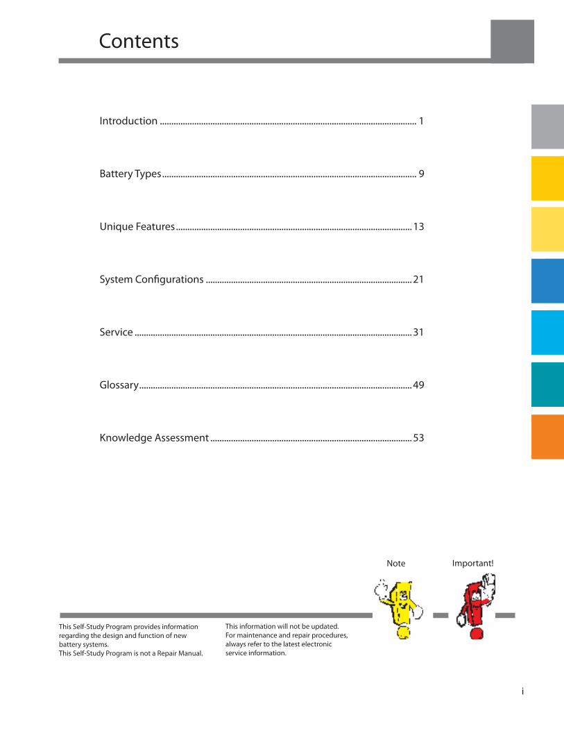
Contents
Note Important!
This Self-Study Program provides information regarding the design and function of new battery systems.This Self-Study Program is not a Repair Manual.
This information will not be updated.For maintenance and repair procedures, always refer to the latest electronic service information.
Introduction ................................................................................................................ 1
Battery Types ............................................................................................................... 9
Unique Features .......................................................................................................13
System Confi gurations ..........................................................................................21
Service .........................................................................................................................31
Glossary .......................................................................................................................49
Knowledge Assessment ........................................................................................53

Page intentionally left blank
ii
Introduction
1
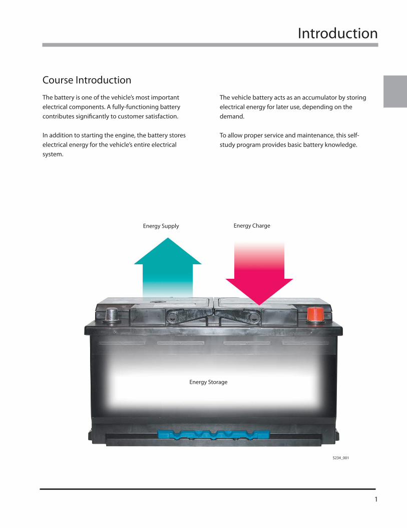
Course Introduction
The battery is one of the vehicle’s most important electrical components. A fully-functioning battery contributes signifi cantly to customer satisfaction.
In addition to starting the engine, the battery stores electrical energy for the vehicle’s entire electrical system.
The vehicle battery acts as an accumulator by storing electrical energy for later use, depending on the demand.
To allow proper service and maintenance, this self-study program provides basic battery knowledge.
Energy Supply Energy Charge
Energy Storage
S234_001
Introduction
2
Introduction
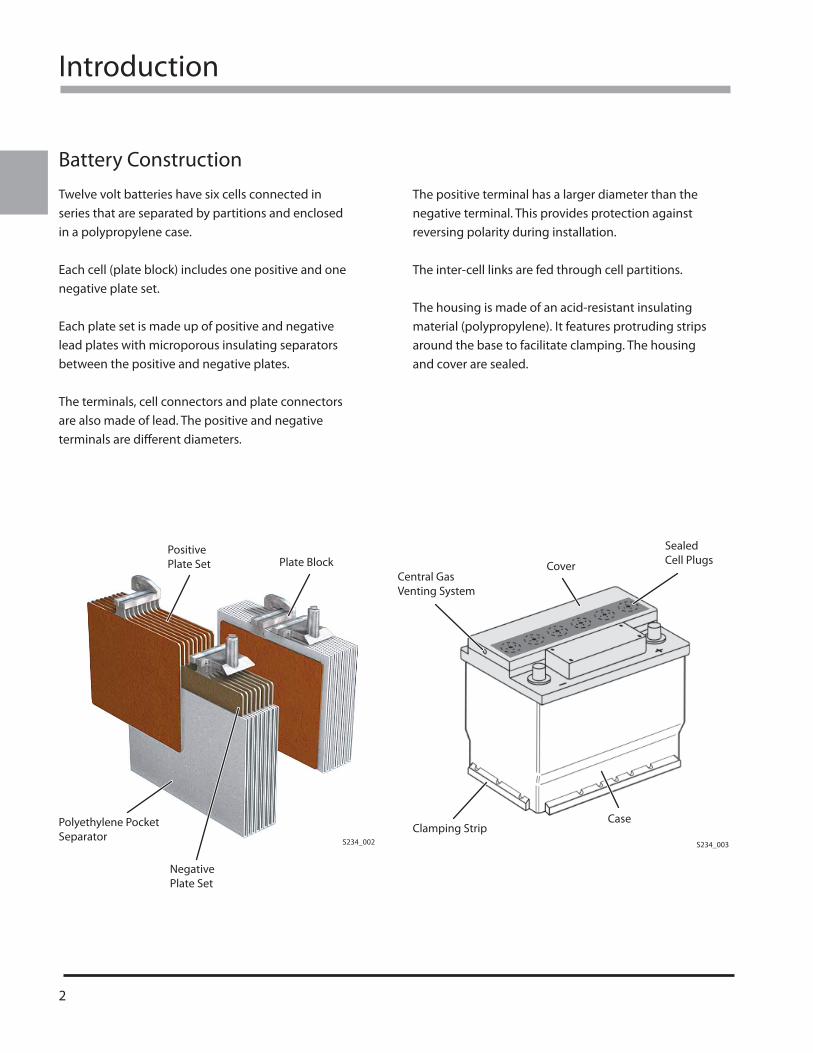
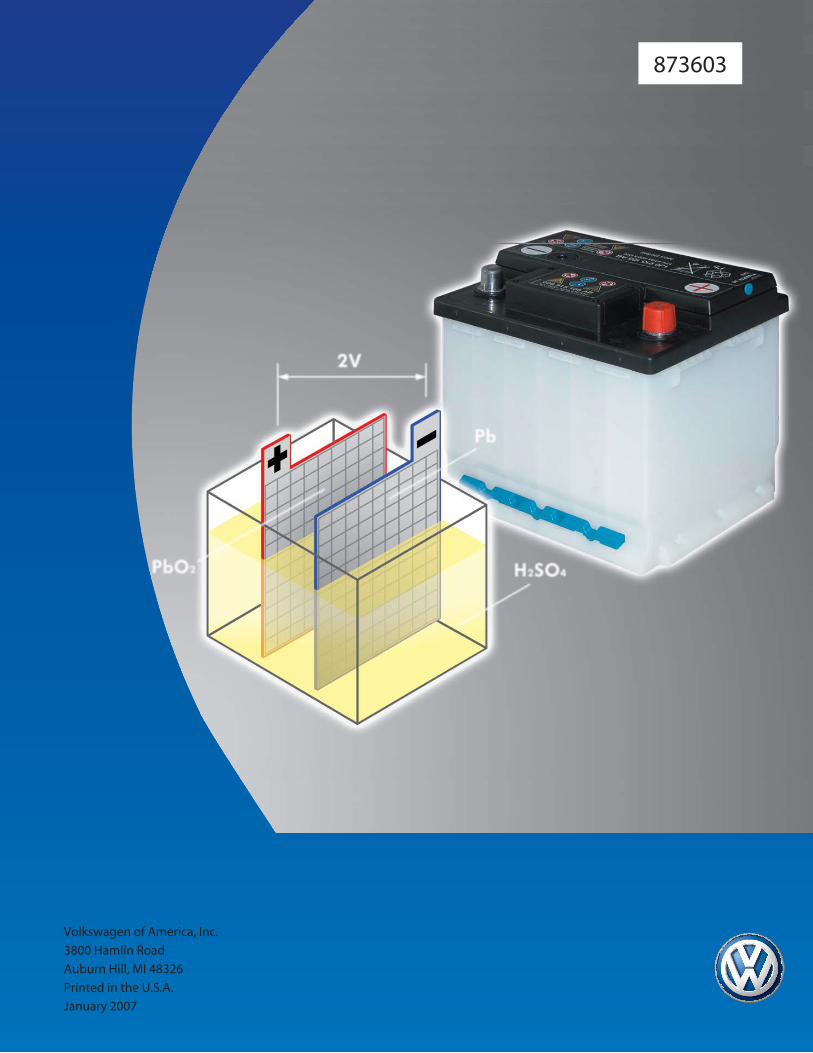
Battery Construction
Twelve volt batteries have six cells connected in series that are separated by partitions and enclosed in a polypropylene case.
Each cell (plate block) includes one positive and one negative plate set.
Each plate set is made up of positive and negative lead plates with microporous insulating separators between the positive and negative plates.
The terminals, cell connectors and plate connectors are also made of lead. The positive and negative terminals are diff erent diameters.
The positive terminal has a larger diameter than the negative terminal. This provides protection against reversing polarity during installation.
The inter-cell links are fed through cell partitions.
The housing is made of an acid-resistant insulating material (polypropylene). It features protruding strips around the base to facilitate clamping. The housing and cover are sealed.
Positive Plate Set Plate Block
Polyethylene Pocket Separator
Negative Plate Set
Central Gas Venting System
Cover
Sealed Cell Plugs
Clamping StripCase
S234_002 S234_003
Introduction
3
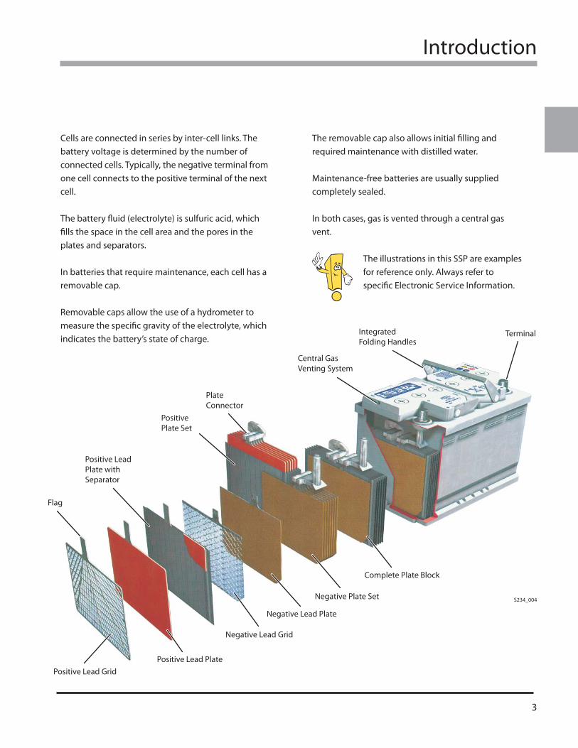
Cells are connected in series by inter-cell links. The battery voltage is determined by the number of connected cells. Typically, the negative terminal from one cell connects to the positive terminal of the next cell.
The battery fl uid (electrolyte) is sulfuric acid, which fi lls the space in the cell area and the pores in the plates and separators.
In batteries that require maintenance, each cell has a removable cap.
Removable caps allow the use of a hydrometer to measure the specifi c gravity of the electrolyte, which indicates the battery’s state of charge.
The removable cap also allows initial fi lling and required maintenance with distilled water.
Maintenance-free batteries are usually supplied completely sealed.
In both cases, gas is vented through a central gas vent.
The illustrations in this SSP are examples for reference only. Always refer to specifi c Electronic Service Information.
Positive LeadPlate with Separator
PositivePlate Set
PlateConnector
Central GasVenting System
IntegratedFolding Handles
Terminal
Complete Plate Block
Negative Plate Set
Negative Lead Plate
Negative Lead Grid
Positive Lead PlatePositive Lead Grid
Flag
S234_004
4
Introduction
Electrolyte
Fluid Electrolyte
Battery fl uid is generally referred to as electrolyte. In a lead-acid battery, electrolyte consists of diluted sulfuric acid.
In a fully-charged battery, the percentage of sulfuric acid is approximately 38%. The percentage of distilled water is approximately 62%. Since electrolyte is ionized, it is capable of conducting an electrical current between the electrodes.
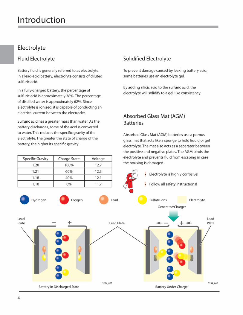
Sulfuric acid has a greater mass than water. As the battery discharges, some of the acid is converted to water. This reduces the specifi c gravity of the electrolyte. The greater the state of charge of the battery, the higher its specifi c gravity.
Specifi c Gravity Charge State Voltage
1.28 100% 12.7
1.21 60% 12.3
1.18 40% 12.1
1.10 0% 11.7
Solidifi ed Electrolyte
To prevent damage caused by leaking battery acid, some batteries use an electrolyte gel.
By adding silicic acid to the sulfuric acid, the electrolyte will solidify to a gel-like consistency.
Absorbed Glass Mat (AGM) Batteries
Absorbed Glass Mat (AGM) batteries use a porous glass mat that acts like a sponge to hold liquid or gel electrolyte. The mat also acts as a separator between the positive and negative plates. The AGM binds the electrolyte and prevents fl uid from escaping in case the housing is damaged.
Electrolyte is highly corrosive!
Follow all safety instructions!
•
•
Lead Plate
Lead PlateLead Plate
Generator/Charger
S234_006S234_005
Battery In Discharged State Battery Under Charge
Hydrogen Oxygen Lead Sulfate Ions Electrolyte
Introduction
5
Charging and Discharging
Charging
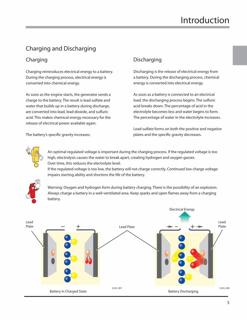
Charging reintroduces electrical energy to a battery. During the charging process, electrical energy is converted into chemical energy.
As soon as the engine starts, the generator sends a charge to the battery. The result is lead sulfate and water that builds up in a battery during discharge, are converted into lead, lead dioxide, and sulfuric acid. This makes chemical energy necessary for the release of electrical power available again.
The battery’s specifi c gravity increases.
Discharging
Discharging is the release of electrical energy from a battery. During the discharging process, chemical energy is converted into electrical energy.
As soon as a battery is connected to an electrical load, the discharging process begins. The sulfuric acid breaks down. The percentage of acid in the electrolyte becomes less and water begins to form. The percentage of water in the electrolyte increases.
Lead sulfate forms on both the positive and negative plates and the specifi c gravity decreases.
An optimal regulated voltage is important during the charging process. If the regulated voltage is too high, electrolysis causes the water to break apart, creating hydrogen and oxygen gasses.Over time, this reduces the electrolyte level. If the regulated voltage is too low, the battery will not charge correctly. Continued low charge voltage impairs starting ability and shortens the life of the battery.
Warning: Oxygen and hydrogen form during battery charging. There is the possibility of an explosion. Always charge a battery in a well-ventilated area. Keep sparks and open fl ames away from a charging battery.
S234_008S234_007Battery In Charged State Battery Discharging
Lead Plate
Lead PlateLead Plate
Electrical Energy
6
Introduction
Battery Terms
Current Charging Factor
The current charging factor is the energy that is introduced in a battery during charging and is more than the energy taken from a battery. This excess compensates for electrochemical losses from charging.
To charge a battery to its maximum of 100%, 105% to 110% of the energy taken from the battery must be reintroduced. This excess energy is the current charging factor.
Capacity
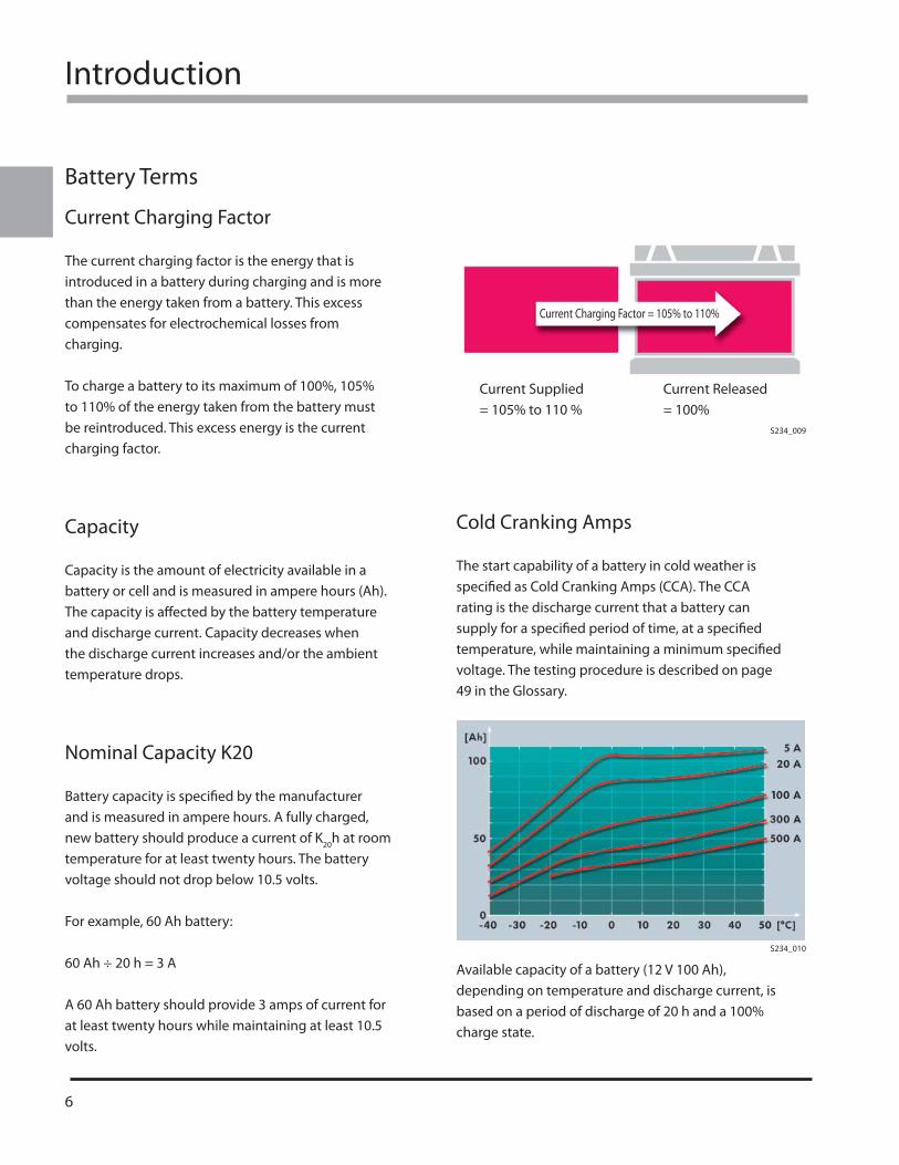
Capacity is the amount of electricity available in a battery or cell and is measured in ampere hours (Ah). The capacity is aff ected by the battery temperature and discharge current. Capacity decreases when the discharge current increases and/or the ambient temperature drops.
Nominal Capacity K20
Battery capacity is specifi ed by the manufacturer and is measured in ampere hours. A fully charged, new battery should produce a current of K20h at room temperature for at least twenty hours. The battery voltage should not drop below 10.5 volts.
For example, 60 Ah battery:
60 Ah ÷ 20 h = 3 A
A 60 Ah battery should provide 3 amps of current for at least twenty hours while maintaining at least 10.5 volts.
Current Charging Factor = 105% to 110%
Current Supplied = 105% to 110 %
Current Released = 100%
Cold Cranking Amps
The start capability of a battery in cold weather is specifi ed as Cold Cranking Amps (CCA). The CCA rating is the discharge current that a battery can supply for a specifi ed period of time, at a specifi ed temperature, while maintaining a minimum specifi ed voltage. The testing procedure is described on page 49 in the Glossary.
S234_009
S234_010
Available capacity of a battery (12 V 100 Ah), depending on temperature and discharge current, is based on a period of discharge of 20 h and a 100% charge state.
Introduction
7
Nominal Voltage
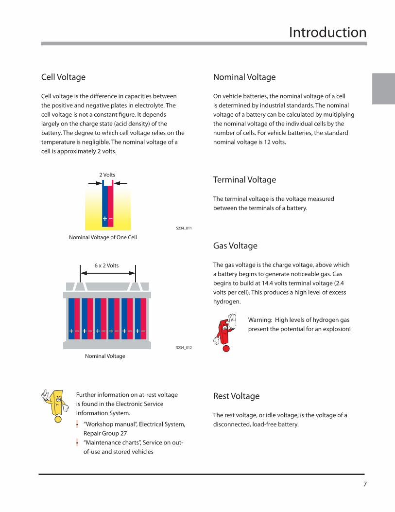
On vehicle batteries, the nominal voltage of a cell is determined by industrial standards. The nominal voltage of a battery can be calculated by multiplying the nominal voltage of the individual cells by the number of cells. For vehicle batteries, the standard nominal voltage is 12 volts.
Terminal Voltage
The terminal voltage is the voltage measured between the terminals of a battery.
Gas Voltage
The gas voltage is the charge voltage, above which a battery begins to generate noticeable gas. Gas begins to build at 14.4 volts terminal voltage (2.4 volts per cell). This produces a high level of excess hydrogen.
Warning: High levels of hydrogen gas present the potential for an explosion!
Rest Voltage
The rest voltage, or idle voltage, is the voltage of a disconnected, load-free battery.
Further information on at-rest voltage is found in the Electronic Service Information System.
“Workshop manual”, Electrical System, Repair Group 27“Maintenance charts”, Service on out-of-use and stored vehicles
•
•
2 Volts
Nominal Voltage of One Cell
S234_011
S234_012
6 x 2 Volts
Nominal Voltage
Cell Voltage
Cell voltage is the diff erence in capacities between the positive and negative plates in electrolyte. The cell voltage is not a constant fi gure. It depends largely on the charge state (acid density) of the battery. The degree to which cell voltage relies on the temperature is negligible. The nominal voltage of a cell is approximately 2 volts.

8
Notes
Battery Types
9
Battery Types
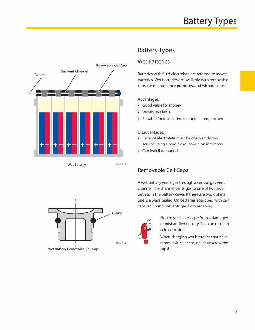
Wet Batteries
Batteries with fl uid electrolyte are referred to as wet batteries. Wet batteries are available with removable caps, for maintenance purposes, and without caps.
Advantages:Good value for money
Widely available
Suitable for installation in engine compartment
Disadvantages:Level of electrolyte must be checked during service using a magic eye (condition indicator)
Can leak if damaged
Removable Cell Caps
A wet battery vents gas through a central gas vent channel. The channel vents gas to one of two side outlets in the battery cover. If there are two outlets, one is always sealed. On batteries equipped with cell caps, an O-ring prevents gas from escaping.
Electrolyte can escape from a damaged or mishandled battery. This can result in acid corrosion!
When charging wet batteries that have removable cell caps, never unscrew the caps!
•
•
•
•
•
OutletGas Vent Channel
Removable Cell Cap
Wet Battery
Wet Battery Removable Cell Cap
O-ring
S234_013
S234_014
10
Battery Types
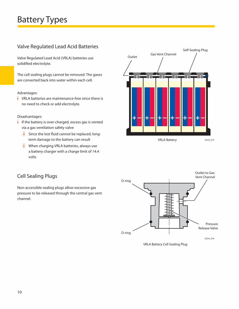
VRLA Battery Cell Sealing Plug
Valve Regulated Lead Acid Batteries
Valve Regulated Lead Acid (VRLA) batteries use solidifi ed electrolyte.
The cell sealing plugs cannot be removed. The gases are converted back into water within each cell.
Advantages:VRLA batteries are maintenance-free since there is no need to check or add electrolyte.
Disadvantages:If the battery is over-charged, excess gas is vented via a gas ventilation safety valve
Since the lost fl uid cannot be replaced, long-term damage to the battery can result
When charging VRLA batteries, always use a battery charger with a charge limit of 14.4 volts
Cell Sealing Plugs
Non-accessible sealing plugs allow excessive gas pressure to be released through the central gas vent channel.
•
•
–
–
OutletGas Vent Channel
Self-Sealing Plug
VRLA Battery
S234_016
O-ring
Outlet to Gas Vent Channel
Pressure Release Valve
O-ring
S234_015
Battery Types
11
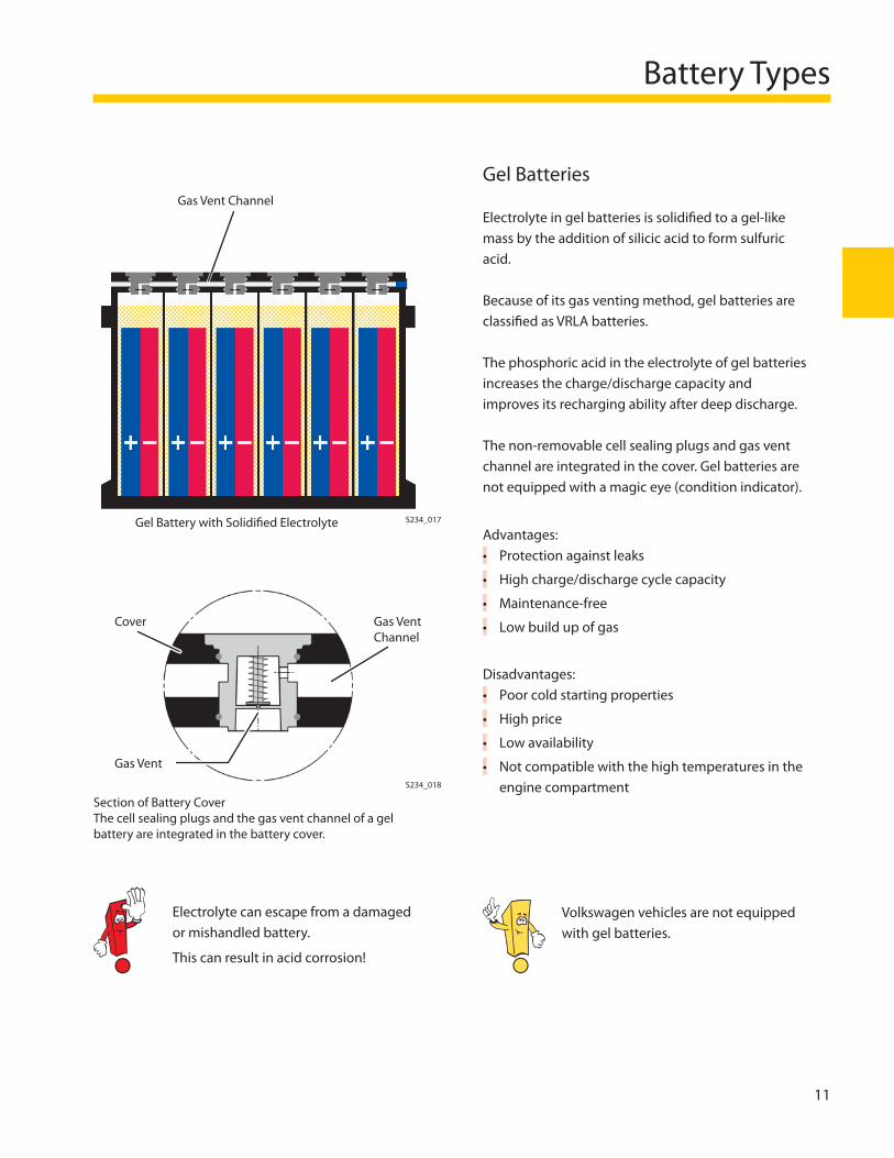
Gel Batteries
Electrolyte in gel batteries is solidifi ed to a gel-like mass by the addition of silicic acid to form sulfuric acid.
Because of its gas venting method, gel batteries are classifi ed as VRLA batteries.
The phosphoric acid in the electrolyte of gel batteries increases the charge/discharge capacity and improves its recharging ability after deep discharge.
The non-removable cell sealing plugs and gas vent channel are integrated in the cover. Gel batteries are not equipped with a magic eye (condition indicator).
Advantages:Protection against leaks
High charge/discharge cycle capacity
Maintenance-free
Low build up of gas
Disadvantages:Poor cold starting properties
High price
Low availability
Not compatible with the high temperatures in the engine compartment
•
•
•
•
•
•
•
•
Gas Vent Channel
Gel Battery with Solidifi ed Electrolyte S234_017
Cover
Gas Vent
Gas Vent Channel
Section of Battery CoverThe cell sealing plugs and the gas vent channel of a gel battery are integrated in the battery cover.
Electrolyte can escape from a damaged or mishandled battery.
This can result in acid corrosion!
S234_018
Volkswagen vehicles are not equipped with gel batteries.
12
Battery Types
Absorbent Glass Mat Batteries
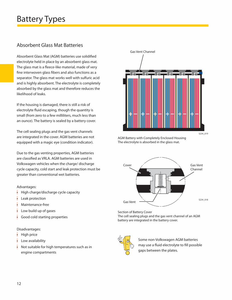
Absorbent Glass Mat (AGM) batteries use solidifi ed electrolyte held in place by an absorbent glass mat. The glass mat is a fl eece-like material, made of very fi ne interwoven glass fi bers and also functions as a separator. The glass mat works well with sulfuric acid and is highly absorbent. The electrolyte is completely absorbed by the glass mat and therefore reduces the likelihood of leaks.
If the housing is damaged, there is still a risk of electrolyte fl uid escaping, though the quantity is small (from zero to a few milliliters, much less than an ounce). The battery is sealed by a battery cover.
The cell sealing plugs and the gas vent channels are integrated in the cover. AGM batteries are not equipped with a magic eye (condition indicator).
Due to the gas venting properties, AGM batteries are classifi ed as VRLA. AGM batteries are used in Volkswagen vehicles when the charge/ discharge cycle capacity, cold start and leak protection must be greater than conventional wet batteries.
Advantages:High charge/discharge cycle capacity
Leak protection
Maintenance-free
Low build up of gases
Good cold starting properties
Disadvantages:High price
Low availability
Not suitable for high temperatures such as in engine compartments
•
•
•
•
•
•
•
•
Cover
Gas Vent
Gas Vent Channel
Section of Battery CoverThe cell sealing plugs and the gas vent channel of an AGM battery are integrated in the battery cover.
AGM Battery with Completely Enclosed HousingThe electrolyte is absorbed in the glass mat.
Gas Vent Channel
S234_019
S234_018
Some non-Volkswagen AGM batteries may use a fl uid electrolyte to fi ll possible gaps between the plates.
Unique Features
13
Properties and Special Features
Central Gas Venting System
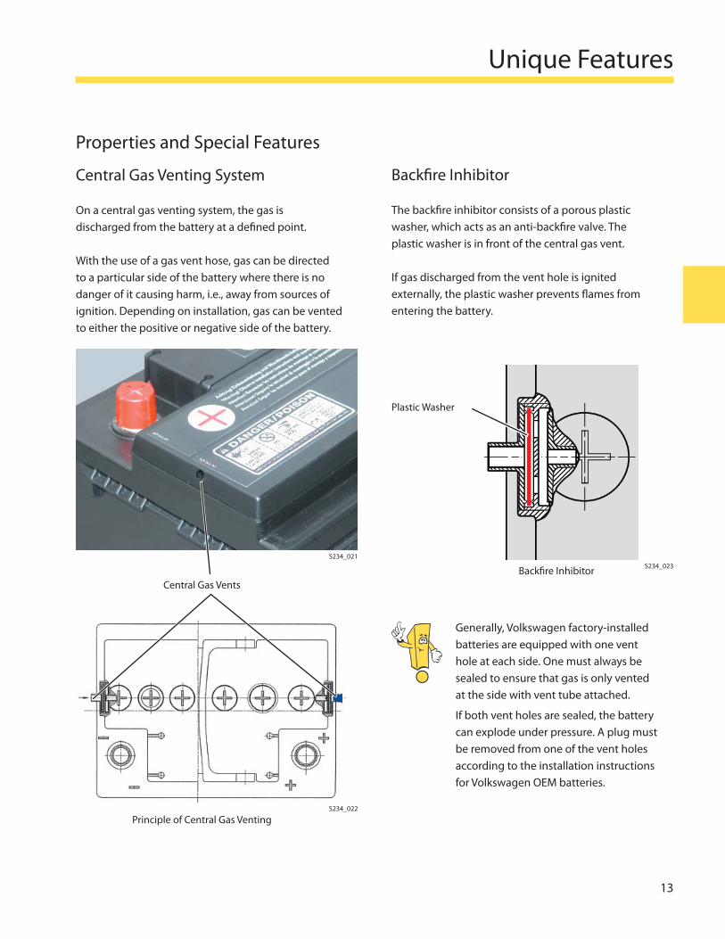
On a central gas venting system, the gas is discharged from the battery at a defi ned point.
With the use of a gas vent hose, gas can be directed to a particular side of the battery where there is no danger of it causing harm, i.e., away from sources of ignition. Depending on installation, gas can be vented to either the positive or negative side of the battery.
Backfi re Inhibitor
The backfi re inhibitor consists of a porous plastic washer, which acts as an anti-backfi re valve. The plastic washer is in front of the central gas vent.
If gas discharged from the vent hole is ignited externally, the plastic washer prevents fl ames from entering the battery.
Generally, Volkswagen factory-installed batteries are equipped with one vent hole at each side. One must always be sealed to ensure that gas is only vented at the side with vent tube attached.
If both vent holes are sealed, the battery can explode under pressure. A plug must be removed from one of the vent holes according to the installation instructions for Volkswagen OEM batteries.
S234_021
Central Gas Vents
Principle of Central Gas VentingS234_022
Plastic Washer
Backfi re Inhibitor S234_023
Unique Features
14
Unique Features
Removable Cell Caps with O-ring
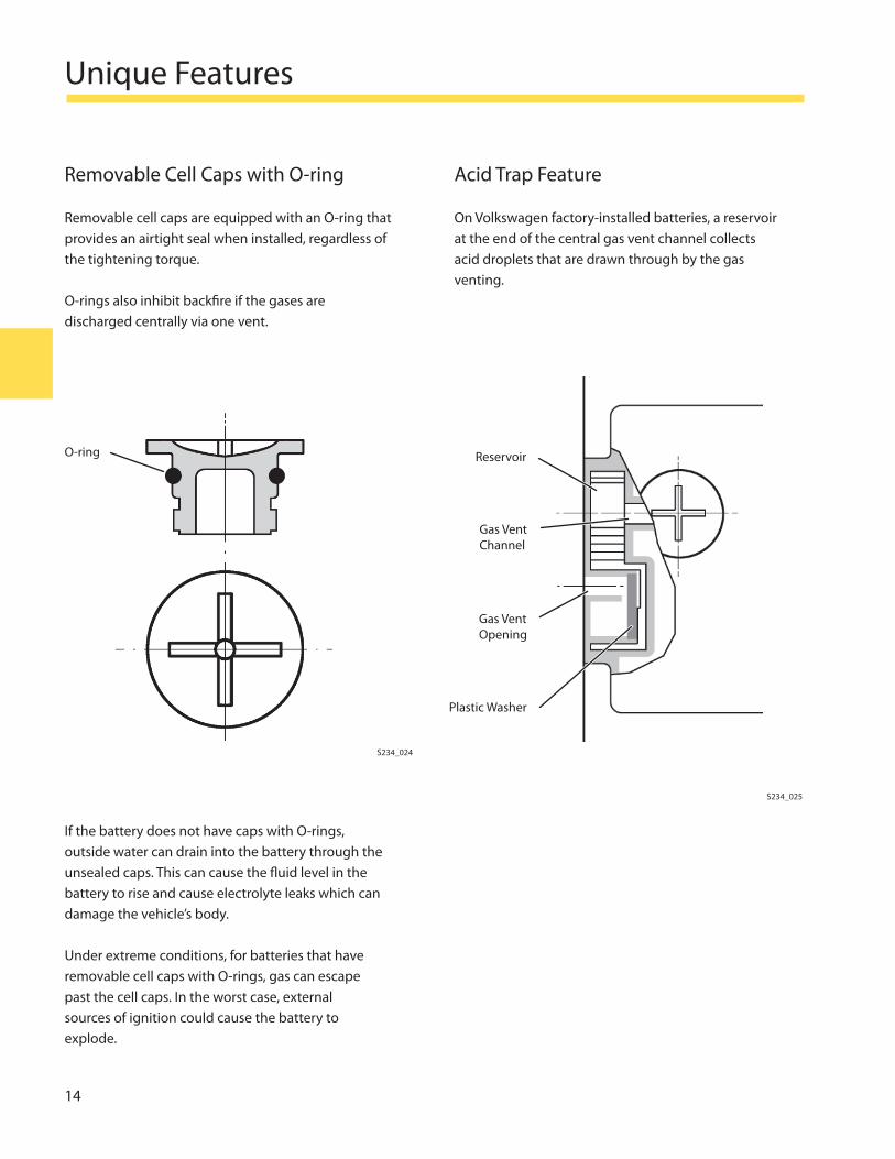
Removable cell caps are equipped with an O-ring that provides an airtight seal when installed, regardless of the tightening torque.
O-rings also inhibit backfi re if the gases are discharged centrally via one vent.
Acid Trap Feature
On Volkswagen factory-installed batteries, a reservoir at the end of the central gas vent channel collects acid droplets that are drawn through by the gas venting.
If the battery does not have caps with O-rings, outside water can drain into the battery through the unsealed caps. This can cause the fl uid level in the battery to rise and cause electrolyte leaks which can damage the vehicle’s body.
Under extreme conditions, for batteries that have removable cell caps with O-rings, gas can escape past the cell caps. In the worst case, external sources of ignition could cause the battery to explode.
S234_024
S234_025
O-ring Reservoir
Gas Vent Channel
Gas Vent Opening
Plastic Washer
Unique Features
15
Magic Eye
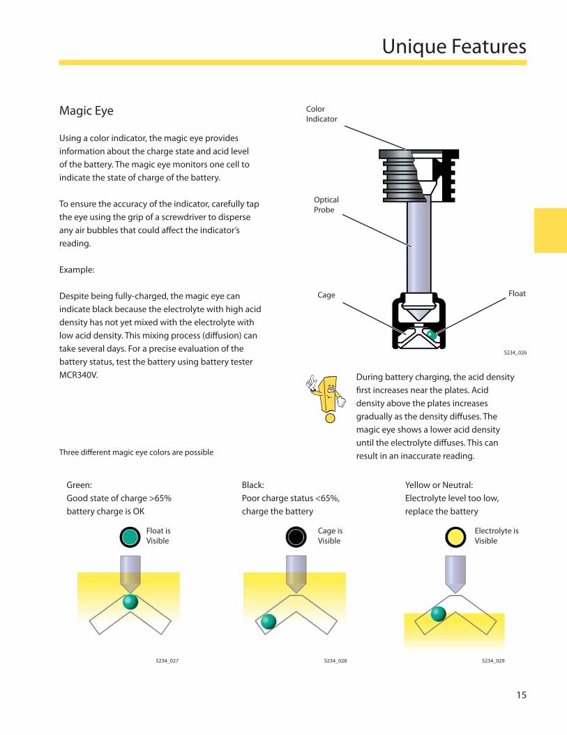
Using a color indicator, the magic eye provides information about the charge state and acid level of the battery. The magic eye monitors one cell to indicate the state of charge of the battery.
To ensure the accuracy of the indicator, carefully tap the eye using the grip of a screwdriver to disperse any air bubbles that could aff ect the indicator’s reading.
Example:
Despite being fully-charged, the magic eye can indicate black because the electrolyte with high acid density has not yet mixed with the electrolyte with low acid density. This mixing process (diff usion) can take several days. For a precise evaluation of the battery status, test the battery using battery tester MCR340V.
Green:Good state of charge >65% battery charge is OK
Black:Poor charge status <65%, charge the battery
Yellow or Neutral:Electrolyte level too low, replace the battery
Float is Visible
Cage is Visible
Electrolyte is Visible
During battery charging, the acid density fi rst increases near the plates. Acid density above the plates increases gradually as the density diff uses. The magic eye shows a lower acid density until the electrolyte diff uses. This can result in an inaccurate reading.
S234_027
S234_026
S234_028 S234_029
Color Indicator
Optical Probe
Cage Float
Three diff erent magic eye colors are possible
16
Unique Features
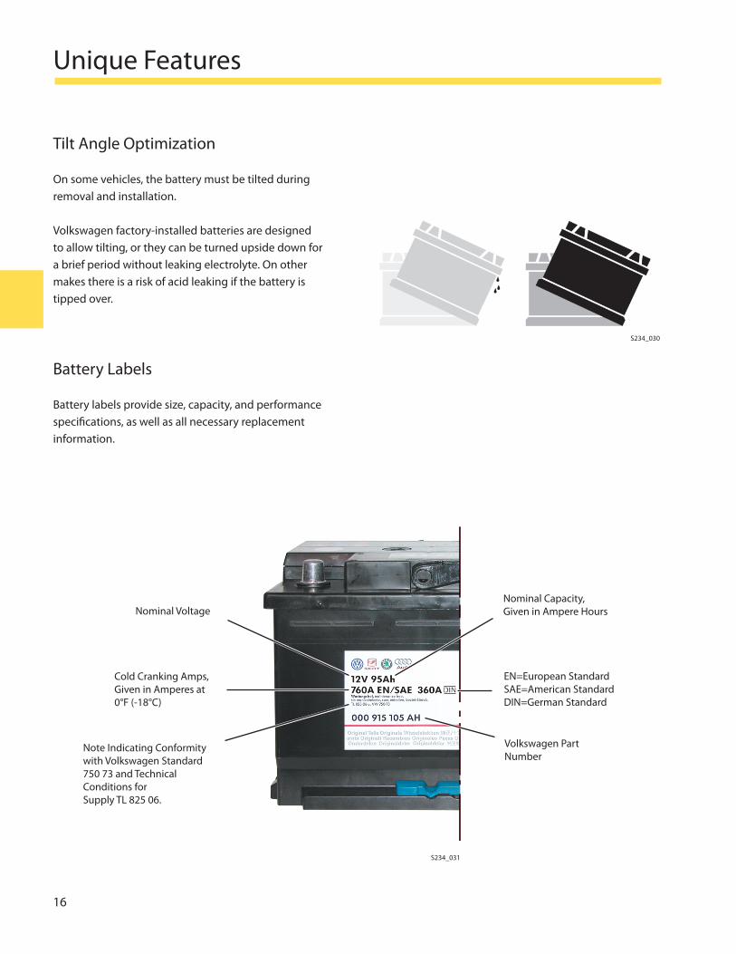
Tilt Angle Optimization
On some vehicles, the battery must be tilted during removal and installation.
Volkswagen factory-installed batteries are designed to allow tilting, or they can be turned upside down for a brief period without leaking electrolyte. On other makes there is a risk of acid leaking if the battery is tipped over.
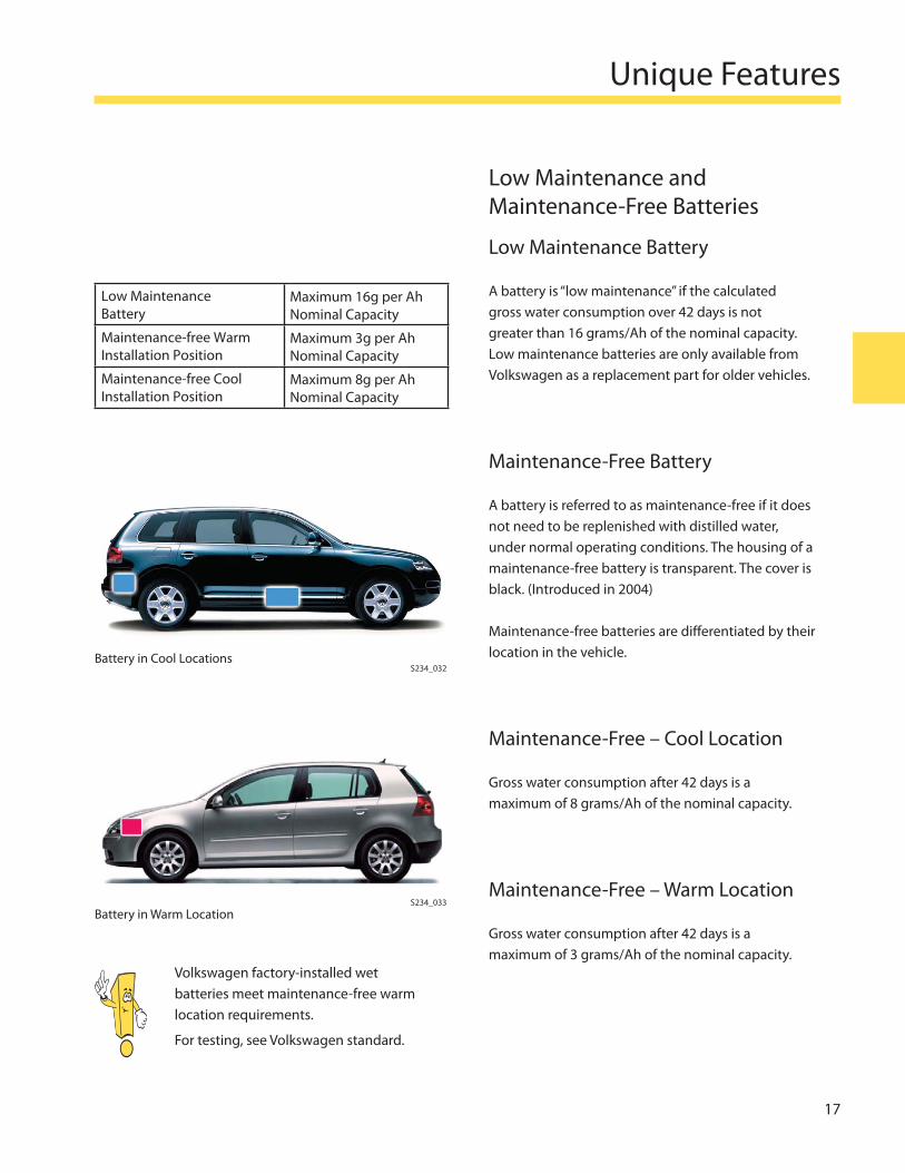
Battery Labels
Battery labels provide size, capacity, and performance specifi cations, as well as all necessary replacement information.
S234_030
S234_031
Note Indicating Conformity with Volkswagen Standard 750 73 and Technical Conditions for Supply TL 825 06.
Nominal Voltage
Cold Cranking Amps, Given in Amperes at 0°F (-18°C)
Nominal Capacity,Given in Ampere Hours
Volkswagen Part Number
EN=European Standard SAE=American Standard DIN=German Standard
Unique Features
17
Low Maintenance and Maintenance-Free Batteries
Low Maintenance Battery
A battery is “low maintenance” if the calculated gross water consumption over 42 days is not greater than 16 grams/Ah of the nominal capacity. Low maintenance batteries are only available from Volkswagen as a replacement part for older vehicles.
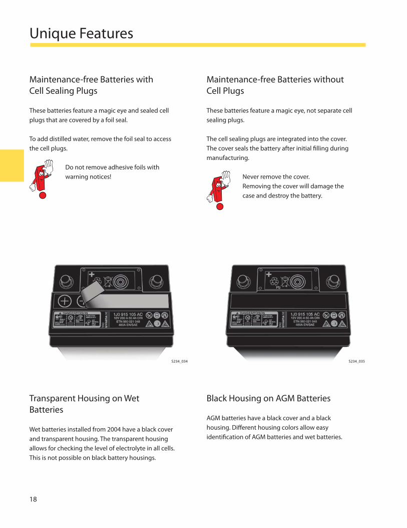
Maintenance-Free Battery
A battery is referred to as maintenance-free if it does not need to be replenished with distilled water, under normal operating conditions. The housing of a maintenance-free battery is transparent. The cover is black. (Introduced in 2004)
Maintenance-free batteries are diff erentiated by their location in the vehicle.
Maintenance-Free – Cool Location
Gross water consumption after 42 days is a maximum of 8 grams/Ah of the nominal capacity.
Maintenance-Free – Warm Location
Gross water consumption after 42 days is a maximum of 3 grams/Ah of the nominal capacity.
S234_032
Low Maintenance Battery
Maximum 16g per Ah Nominal Capacity
Maintenance-free Warm Installation Position
Maximum 3g per Ah Nominal Capacity
Maintenance-free Cool Installation Position
Maximum 8g per Ah Nominal Capacity
S234_033
Battery in Cool Locations
Battery in Warm Location
Volkswagen factory-installed wet batteries meet maintenance-free warm location requirements.
For testing, see Volkswagen standard.
18
Unique Features
Maintenance-free Batteries with Cell Sealing Plugs
These batteries feature a magic eye and sealed cell plugs that are covered by a foil seal.
To add distilled water, remove the foil seal to access the cell plugs.
Do not remove adhesive foils with warning notices!
Maintenance-free Batteries without Cell Plugs
These batteries feature a magic eye, not separate cell sealing plugs.
The cell sealing plugs are integrated into the cover. The cover seals the battery after initial fi lling during manufacturing.
Never remove the cover. Removing the cover will damage the case and destroy the battery.
Transparent Housing on Wet Batteries
Wet batteries installed from 2004 have a black cover and transparent housing. The transparent housing allows for checking the level of electrolyte in all cells. This is not possible on black battery housings.
Black Housing on AGM Batteries
AGM batteries have a black cover and a black housing. Diff erent housing colors allow easy identifi cation of AGM batteries and wet batteries.
S234_034 S234_035
Unique Features
19
Battery Locations
The installation position or where the battery is located in the vehicle has a signifi cant aff ect on the battery’s performance.
The installation position of a vehicle’s battery must meet many criteria:
Good accessibility for service and repair
Protection from excessive heat and air cooling when the vehicle is in motion
Protection from dampness, oil and fuels, also any form of mechanical shock
Protection from escaping gases and leaking battery acid for the vehicle’s occupants in the event of a crash
•
•
•
•
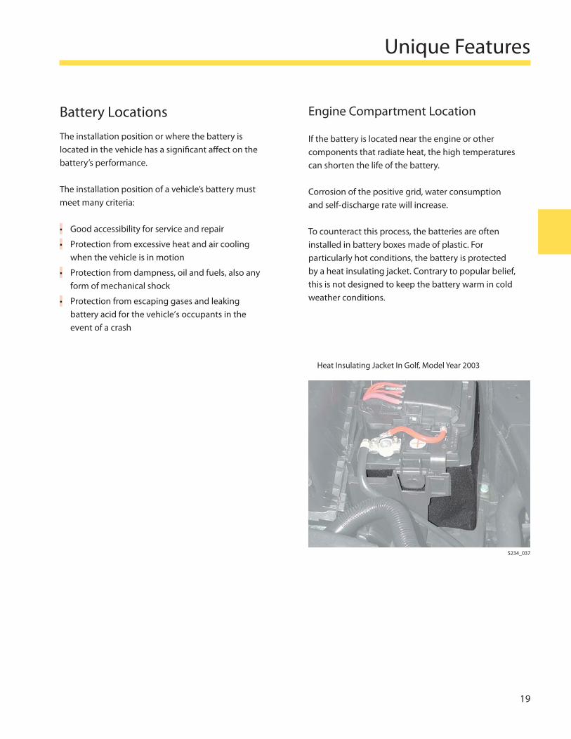
Engine Compartment Location
If the battery is located near the engine or other components that radiate heat, the high temperatures can shorten the life of the battery.
Corrosion of the positive grid, water consumption and self-discharge rate will increase.
To counteract this process, the batteries are often installed in battery boxes made of plastic. For particularly hot conditions, the battery is protected by a heat insulating jacket. Contrary to popular belief, this is not designed to keep the battery warm in cold weather conditions.
Heat Insulating Jacket In Golf, Model Year 2003
S234_037
20
Unique Features
Interior or Luggage Compartment Location
If the battery is located inside the vehicle, a wet battery with optimized tilt angle properties, or an AGM battery with anti-leak protection is used. Batteries installed on the inside of the vehicle are also equipped with a gas vent hose to prevent injury from leaking battery acid in the event of a rollover accident with the vehicle coming to rest on its roof. Tilt angle optimized or anti-leak batteries minimizes the risk of acid burns.
When replacing a battery choose one with Volkswagen factory-installed battery features
Ensure the gas vent hose is inserted into the central gas vent opening of the battery
•
•
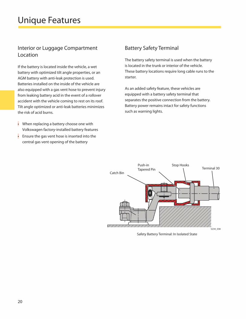
Battery Safety Terminal
The battery safety terminal is used when the battery is located in the trunk or interior of the vehicle. These battery locations require long cable runs to the starter.
As an added safety feature, these vehicles are equipped with a battery safety terminal that separates the positive connection from the battery. Battery power remains intact for safety functions such as warning lights.
Safety Battery Terminal: In Isolated State
S234_038
Terminal 30Catch Bin
Push-in Tapered Pin
Stop Hooks
System Confi gurations
21
System Confi guration Factors
Factors aff ecting vehicle electrical system include: battery capacity, electrical loads, generator output, generator ratio, idle speed of the engine and driving conditions.
A balance between energy input (charge) and energy output (discharge) provides an ideal electrical system
Additional electrical loads installed in the vehicle or demanding operating conditions can aff ect overall performance of the electrical system
The vehicle’s battery provides a power source for various electrical loads such as lights and sound systems. The battery must be continually charged by the generator. If the energy demand on the battery is greater than the energy supplied by the generator, the battery discharges.
•
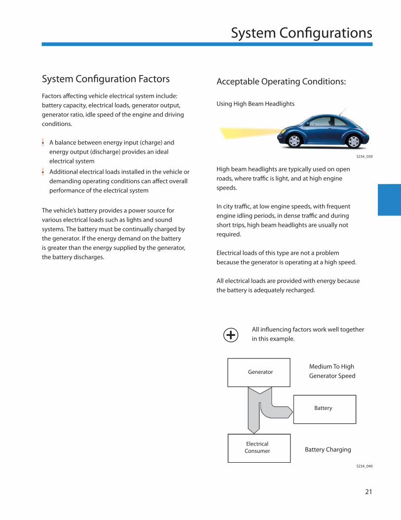
• High beam headlights are typically used on open roads, where traffi c is light, and at high engine speeds.
In city traffi c, at low engine speeds, with frequent engine idling periods, in dense traffi c and during short trips, high beam headlights are usually not required.
Electrical loads of this type are not a problem because the generator is operating at a high speed.
All electrical loads are provided with energy because the battery is adequately recharged.
All infl uencing factors work well together in this example.
Medium To High Generator Speed
Generator
Battery
Electrical Consumer Battery Charging
S234_040
S234_039
System Confi gurations
Acceptable Operating Conditions:
Using High Beam Headlights
22
System Confi gurations
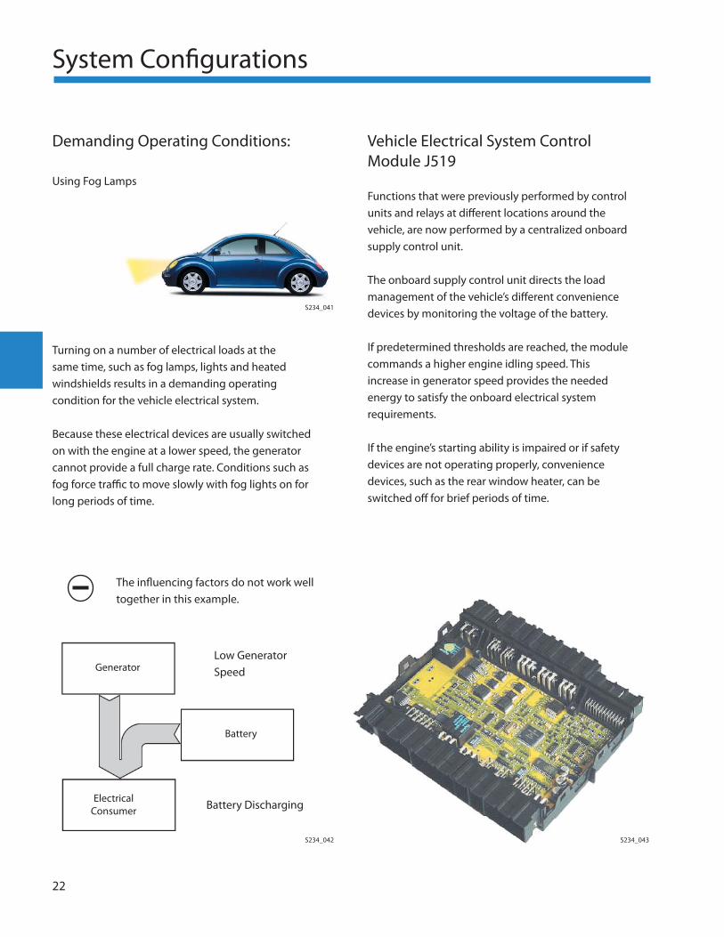
Demanding Operating Conditions:
Using Fog Lamps
Turning on a number of electrical loads at the same time, such as fog lamps, lights and heated windshields results in a demanding operating condition for the vehicle electrical system.
Because these electrical devices are usually switched on with the engine at a lower speed, the generator cannot provide a full charge rate. Conditions such as fog force traffi c to move slowly with fog lights on for long periods of time.
Vehicle Electrical System Control Module J519
Functions that were previously performed by control units and relays at diff erent locations around the vehicle, are now performed by a centralized onboard supply control unit.
The onboard supply control unit directs the load management of the vehicle’s diff erent convenience devices by monitoring the voltage of the battery.
If predetermined thresholds are reached, the module commands a higher engine idling speed. This increase in generator speed provides the needed energy to satisfy the onboard electrical system requirements.
If the engine’s starting ability is impaired or if safety devices are not operating properly, convenience devices, such as the rear window heater, can be switched off for brief periods of time.
S234_041
S234_042 S234_043
Low Generator SpeedGenerator
Battery
Electrical Consumer Battery Discharging
The infl uencing factors do not work well together in this example.
System Confi gurations
23
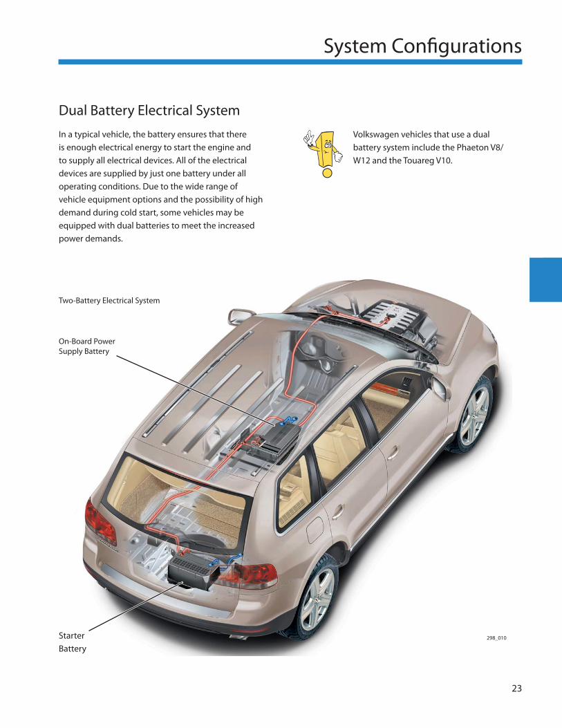
Volkswagen vehicles that use a dual battery system include the Phaeton V8/W12 and the Touareg V10.
Dual Battery Electrical System
In a typical vehicle, the battery ensures that there is enough electrical energy to start the engine and to supply all electrical devices. All of the electrical devices are supplied by just one battery under all operating conditions. Due to the wide range of vehicle equipment options and the possibility of high demand during cold start, some vehicles may be equipped with dual batteries to meet the increased power demands.
298_010
Two-Battery Electrical System
On-Board Power Supply Battery
Starter Battery
24
System Confi gurations
Dual Battery System
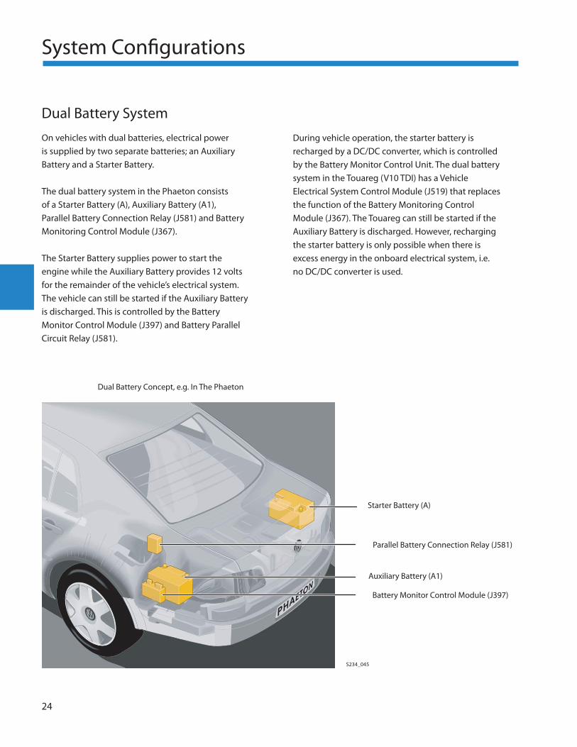
On vehicles with dual batteries, electrical power is supplied by two separate batteries; an Auxiliary Battery and a Starter Battery.
The dual battery system in the Phaeton consists of a Starter Battery (A), Auxiliary Battery (A1), Parallel Battery Connection Relay (J581) and Battery Monitoring Control Module (J367).
The Starter Battery supplies power to start the engine while the Auxiliary Battery provides 12 volts for the remainder of the vehicle’s electrical system. The vehicle can still be started if the Auxiliary Battery is discharged. This is controlled by the Battery Monitor Control Module (J397) and Battery Parallel Circuit Relay (J581).
During vehicle operation, the starter battery is recharged by a DC/DC converter, which is controlled by the Battery Monitor Control Unit. The dual battery system in the Touareg (V10 TDI) has a Vehicle Electrical System Control Module (J519) that replaces the function of the Battery Monitoring Control Module (J367). The Touareg can still be started if the Auxiliary Battery is discharged. However, recharging the starter battery is only possible when there is excess energy in the onboard electrical system, i.e. no DC/DC converter is used.
Dual Battery Concept, e.g. In The Phaeton
Starter Battery (A)
Parallel Battery Connection Relay (J581)
Auxiliary Battery (A1)
Battery Monitor Control Module (J397)
S234_045
System Confi gurations
25
Battery and Generator Balance
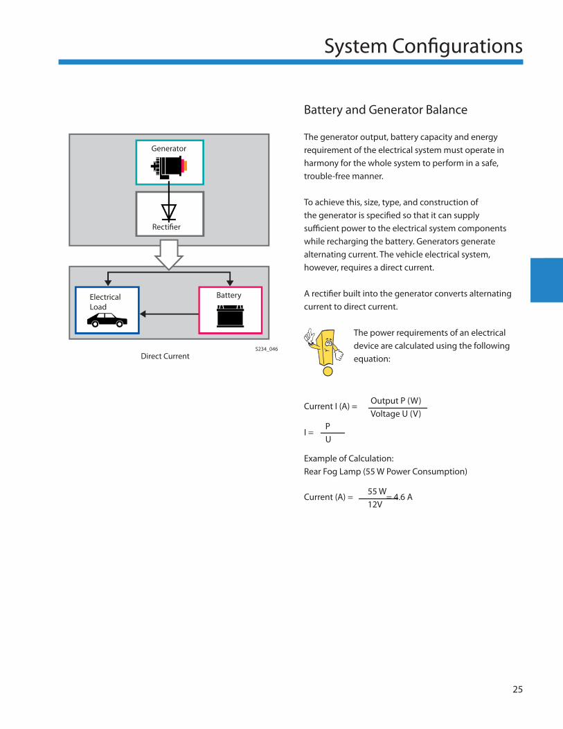
The generator output, battery capacity and energy requirement of the electrical system must operate in harmony for the whole system to perform in a safe, trouble-free manner.
To achieve this, size, type, and construction of the generator is specifi ed so that it can supply suffi cient power to the electrical system components while recharging the battery. Generators generate alternating current. The vehicle electrical system, however, requires a direct current.
A rectifi er built into the generator converts alternating current to direct current.
The power requirements of an electrical device are calculated using the following equation:
Current I (A) =
I =
Example of Calculation:Rear Fog Lamp (55 W Power Consumption)
Current (A) = = 4.6 A
Output P (W) Voltage U (V)
P U
55 W 12V
Generator
Rectifi er
ElectricalLoad
Battery
S234_046Direct Current
26
System Confi gurations
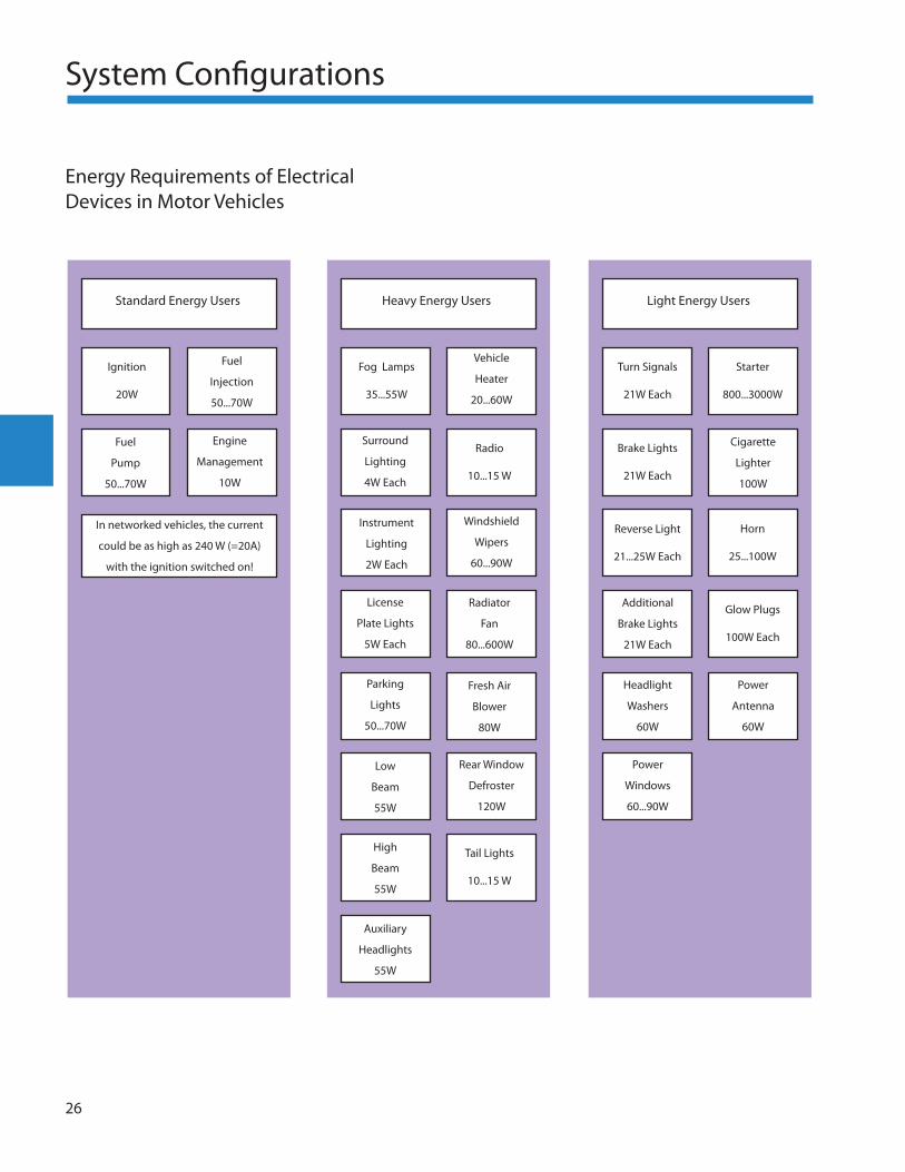
Energy Requirements of Electrical Devices in Motor Vehicles
Standard Energy Users Heavy Energy Users Light Energy Users
Ignition
20W
Fuel
Injection
50...70W
Fuel
Pump
50...70W
Engine
Management
10W
In networked vehicles, the current
could be as high as 240 W (=20A)
with the ignition switched on!
Fog Lamps
35...55W
Vehicle
Heater
20...60W
Surround
Lighting
4W Each
Radio
10...15 W
Instrument
Lighting
2W Each
Windshield
Wipers
60...90W
License
Plate Lights
5W Each
Radiator
Fan
80...600W
Parking
Lights
50...70W
Fresh Air
Blower
80W
Rear Window
Defroster
120W
High
Beam
55W
Low
Beam
55W
Tail Lights
10...15 W
Auxiliary
Headlights
55W
Turn Signals
21W Each
Starter
800...3000W
Brake Lights
21W Each
Reverse Light
21...25W Each
Horn
25...100W
Glow Plugs
100W Each
Cigarette
Lighter
100W
Power
Antenna
60W
Headlight
Washers
60W
Additional
Brake Lights
21W Each
Power
Windows
60...90W
System Confi gurations
27
Battery Storage and Self-discharge
Chemically Induced Self-discharge
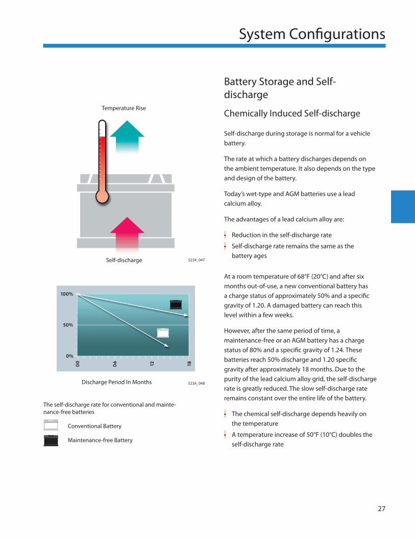
Self-discharge during storage is normal for a vehicle battery.
The rate at which a battery discharges depends on the ambient temperature. It also depends on the type and design of the battery.
Today’s wet-type and AGM batteries use a lead calcium alloy.
The advantages of a lead calcium alloy are:
Reduction in the self-discharge rate
Self-discharge rate remains the same as the battery ages
At a room temperature of 68°F (20°C) and after six months out-of-use, a new conventional battery has a charge status of approximately 50% and a specifi c gravity of 1.20. A damaged battery can reach this level within a few weeks.
However, after the same period of time, a maintenance-free or an AGM battery has a charge status of 80% and a specifi c gravity of 1.24. These batteries reach 50% discharge and 1.20 specifi c gravity after approximately 18 months. Due to the purity of the lead calcium alloy grid, the self-discharge rate is greatly reduced. The slow self-discharge rate remains constant over the entire life of the battery.
The chemical self-discharge depends heavily on the temperature
A temperature increase of 50°F (10°C) doubles the self-discharge rate
•
•
•
•
S234_047Self-discharge
S234_048Discharge Period In Months
Temperature Rise
The self-discharge rate for conventional and mainte-nance-free batteries
Conventional Battery
Maintenance-free Battery
28
System Confi gurations
Parasitic Drain
Another reason for the discharge of vehicle batteries is idle current draw or parasitic drain.
A constant load is placed on the battery, depending on the vehicle equipment options, by electrical devices that are always active.
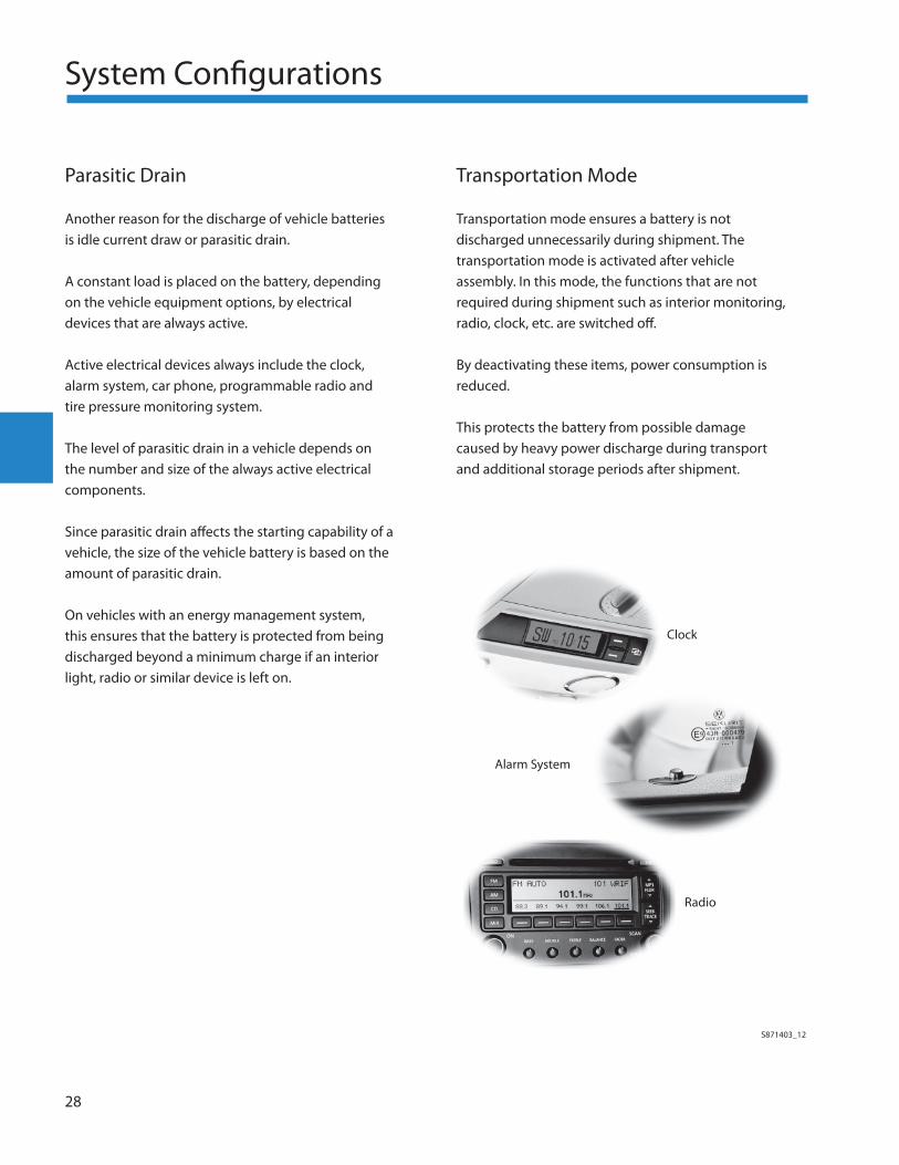
Active electrical devices always include the clock, alarm system, car phone, programmable radio and tire pressure monitoring system.
The level of parasitic drain in a vehicle depends on the number and size of the always active electrical components.
Since parasitic drain aff ects the starting capability of a vehicle, the size of the vehicle battery is based on the amount of parasitic drain.
On vehicles with an energy management system, this ensures that the battery is protected from being discharged beyond a minimum charge if an interior light, radio or similar device is left on.
Transportation Mode
Transportation mode ensures a battery is not discharged unnecessarily during shipment. The transportation mode is activated after vehicle assembly. In this mode, the functions that are not required during shipment such as interior monitoring, radio, clock, etc. are switched off .
By deactivating these items, power consumption is reduced.
This protects the battery from possible damage caused by heavy power discharge during transport and additional storage periods after shipment.
Clock
S871403_12
Alarm System
Radio
System Confi gurations
29
High Temperatures
High temperatures accelerate chemical reactions in the battery.
The performance of a battery increases as a result of the lower viscosity of the electrolyte
The battery’s capacity increases slightly
However, higher temperatures increase corrosion of the plates and grids
At high temperatures, the rate of chemical self-discharge also increases
•
–
•
•
Low Temperatures
As temperatures fall, the battery’s capacity decreases. Chemical processes are not as eff ective at low temperatures due to the increase in viscosity of the electrolyte.
The battery capacity should be matched to its intended operating environment. At extremely low temperatures, an under capacity battery may not crank the starter at the speed necessary to start the engine.
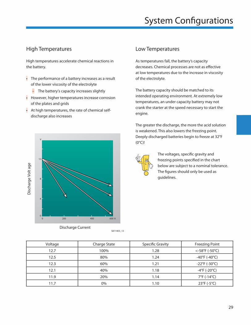
The greater the discharge, the more the acid solution is weakened. This also lowers the freezing point. Deeply discharged batteries begin to freeze at 32°F (0°C)!
The voltages, specifi c gravity and freezing points specifi ed in the chart below are subject to a nominal tolerance. The fi gures should only be used as guidelines.
Discharge Current
Voltage Charge State Specifi c Gravity Freezing Point
12.7 100% 1.28 <-58°F (-50°C)
12.5 80% 1.24 -40°F (-40°C)
12.3 60% 1.21 -22°F (-30°C)
12.1 40% 1.18 -4°F (-20°C)
11.9 20% 1.14 7°F (-14°C)
11.7 0% 1.10 23°F (-5°C)
S871403_13
Dis
char
ge V
olt a
ge
00
4
8
12
200 400 600 A
V
30
System Confi gurations
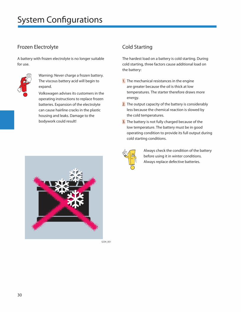
Frozen Electrolyte
A battery with frozen electrolyte is no longer suitable for use.
Warning: Never charge a frozen battery. The viscous battery acid will begin to expand.
Volkswagen advises its customers in the operating instructions to replace frozen batteries. Expansion of the electrolyte can cause hairline cracks in the plastic housing and leaks. Damage to the bodywork could result!
Cold Starting
The hardest load on a battery is cold starting. During cold starting, three factors cause additional load on the battery:
The mechanical resistances in the engine are greater because the oil is thick at low temperatures. The starter therefore draws more energy.
The output capacity of the battery is considerably less because the chemical reaction is slowed by the cold temperatures.
The battery is not fully charged because of the low temperature. The battery must be in good operating condition to provide its full output during cold starting conditions.
Always check the condition of the battery before using it in winter conditions. Always replace defective batteries.
1.
2.
3.
S234_051
Service
31
Battery Testing
Battery Installation
Check the battery for proper and secure installation in the vehicle. Vibrations from an improperly secured battery can damage grid plates and signifi cantly shorten the life of the battery.
A poorly secured battery could be damaged and explode during a crash.
Periodically check the battery clamp plate to ensure that the plate is positioned correctly on the base strip. Use an adapter if necessary.
Ensure the battery clamp plate bolt is tightened to the specifi ed torque.
A groove in the side of the battery base allows the battery to be clamped on one side or two, depending on the vehicle design.
To ensure proper installation, always check the battery’s mounting before placing the vehicle in service.
S234_052
Service
Visual Inspection
Before performing any battery tests such as parasitic drain test, specifi c gravity test, or a load test, inspect the battery visually for damage, loose connections, and improper installation. Inspect the outside of the battery as follows.
Battery Housing
Check for acid leaks. Acid is corrosive and can cause damage to the vehicle body parts and components. Immediately clean any parts aff ected by acid leaks with a soap and water solution or replace the parts.
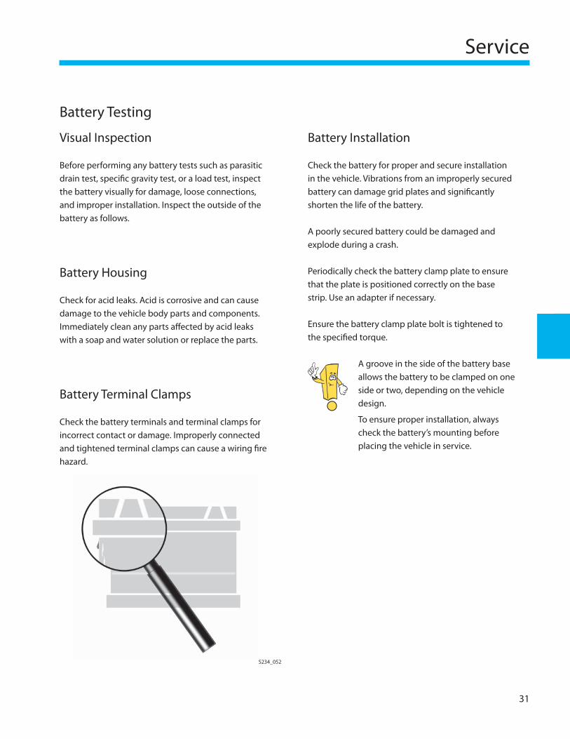
Battery Terminal Clamps
Check the battery terminals and terminal clamps for incorrect contact or damage. Improperly connected and tightened terminal clamps can cause a wiring fi re hazard.
32
Service
Battery Testing
Display/Print-out Action
Good Battery None
Good–Recharge Charge Battery if Necessary*
Use InCharge Charge Battery*
Replace Battery Replace Battery
Bad Cell–Replace Replace Battery
*Repeat Load Test After Recharging Battery
S234_056
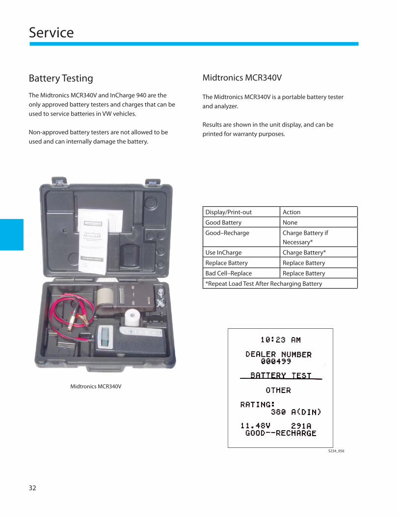
Midtronics MCR340V
The Midtronics MCR340V and InCharge 940 are the only approved battery testers and charges that can be used to service batteries in VW vehicles.
Non-approved battery testers are not allowed to be used and can internally damage the battery.
Midtronics MCR340V
The Midtronics MCR340V is a portable battery tester and analyzer.
Results are shown in the unit display, and can be printed for warranty purposes.
Service
33
Read battery tester operating instructions. Follow all instructions given in the Electronic Service Information System.
The battery can only accommodate a single load test. Before repeating the test, recharge the battery.
Load Testing
Load capability is the amount of current draw (amperes) that a fully-charged battery can provide for a set period of time, at a defi ned temperature, without falling below a prescribed voltage.
To perform the battery load test, the Midtromics INC-940 Battery Charger is required.
When performing a load test using the INC-940, it is not necessary to remove or disconnect the battery
Test readings may be required to process warranty claims
•
•
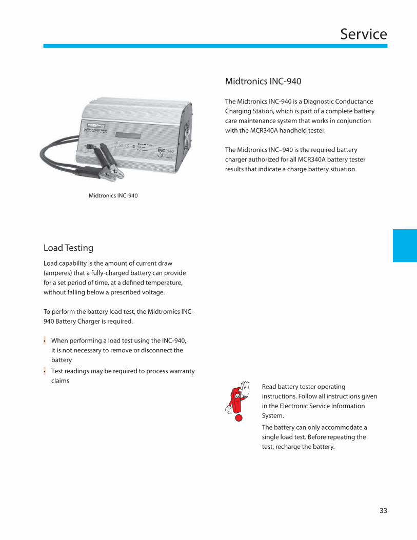
Midtronics INC-940
Midtronics INC-940
The Midtronics INC-940 is a Diagnostic Conductance Charging Station, which is part of a complete battery care maintenance system that works in conjunction with the MCR340A handheld tester.
The Midtronics INC–940 is the required battery charger authorized for all MCR340A battery tester results that indicate a charge battery situation.
34
Service
Test Results Not Shown
If after connecting the MCR340V tester to a battery, the tester displays no results, perform the following:
Ensure the clamps are connected properly
Ensure the battery is not completely discharged (less than 1 volt)
This prevents the internal circuitry of the tester and charger from identifying that a battery is connected
Connect the battery to the Midtronics InCharge-940 Battery Charging Station (INC-940) and charge manually for 10 to 15 minutes to increase the voltage
When charging, always use the DIN value listed on the battery label
When charging a battery from remote terminals, refer to Vehicle Service Information, or Bulletins, for the appropriate reduced DIN value
Restart in Automatic mode on the INC-940. In the automatic mode, the charger will indicate either a good or bad battery
A test code is generated only in the automatic mode.
•
•
–
•
–
–
–
Test Good But No Start
If the battery tests GOOD, but the vehicle does not start, perform the following:
If the tester or charger shows good battery, but the vehicle fails to start, inspect the connections to the battery, starter, and generator for wear and corrosion
If the MCR340V shows a “good battery”, “good recharge” the latter indicates that the battery is good, but charging is necessary
This means that the battery may still be good, but is too discharged to start the vehicle
Diagnose the vehicle to determine cause of the discharged battery and place the battery on the INC-940 for charging
•
•
–
•
When charging any battery, always use the Midtronics INC-940 Battery Charging Station.
A battery under warranty cannot be replaced without a test result that says REPLACE and the 14-digit encrypted test code.
There are other non-electrical defects (swelling of the case, loose terminals, cracks) that also require replacement but cannot be documented by the MCR340V or the INC-940.
Service
35
Battery Charging
Charging Deeply Discharged Batteries
If a battery is not used for a long period of time, it will begin to self-discharge. A battery can also be discharged by parasitic drain if it is not disconnected. A battery that is in a state of deep discharge has a specifi c gravity below 1.14
Deeply discharged batteries can freeze in the winter due to the high percentage of water in the electrolyte. Replace frozen batteries. Hairline cracks in the case may exist that are not visible.
Deeply discharged batteries begin to sulfate, the plate surface of the battery hardens. If deeply discharged batteries are recharged immediately following deep discharge, sulfate reforms. If not charged, the plates will continue to harden and the battery will lose its ability to take a charge.
Charge the battery for 30 minutes and repeat the test using the MCR340V
If a deeply discharged battery is charged too quickly it will not accept the charge current, or it will show a false “full” reading because of a “surface charge”
The battery will only appear to be charged
Deeply discharged batteries often accept only a low charge rate at the beginning of a recharge
A deeply discharged battery from a stored vehicle should be replaced
•
•
•
•
•
Charging
The following procedures for battery maintenance are for refernce only. Always check the current Electronic Service Information to assure that you are using the correct procedures.
If the battery load test indicates that recharging is required, observe the following procedures.
Follow all accident prevention instructionsEnsure the space is well ventilatedEnsure the battery temperature is at least 50°F (10°C) Stop all charging activity if the battery electrolyte reaches 131°F (55°C) or higher Never fast charge a battery! Fast charging damages the battery
The following special tools are approved by Volkswagen for battery recharging:
Midtronics CXC-2115 Battery Maintainer (sales fl oor use only)
Midtronics InCharge-940 Battery Charging Station
Midtronics PSC 550 Battery Maintainer
Read battery charger operating instructions before use.
Follow the instructions provided in the Electronic Service Information System.
•
••
•
•
•
•
•
36
Service
Battery Recharging
Maintaining a Charge
On vehicles that are stored for long periods of time, the battery charge is lowered because of parasitic drain and temperature changes.
As a result, the ability of the battery to charge is permanently reduced.
To counteract this discharge process on storage vehicles, a system is introduced to help maintain the charge
The battery is kept fully-charged by a constant voltage charger unit, which provides a low current charge to the battery
The following special tools are approved by Volkswagen for battery maintenance:
CS5Q-5D Solar Battery Charger
Midtronics CXC-2115 Battery Maintainer
Midtronics InCharge-940 Battery Charging Station
Midtronics PSC 550 Battery Maintainer
•
•
•
•
•
•
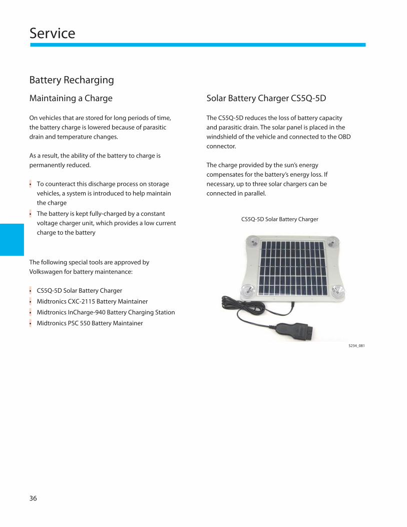
Solar Battery Charger CS5Q-5D
The CS5Q-5D reduces the loss of battery capacity and parasitic drain. The solar panel is placed in the windshield of the vehicle and connected to the OBD connector.
The charge provided by the sun’s energy compensates for the battery’s energy loss. If necessary, up to three solar chargers can be connected in parallel.
CS5Q-5D Solar Battery Charger
S234_081
Service
37
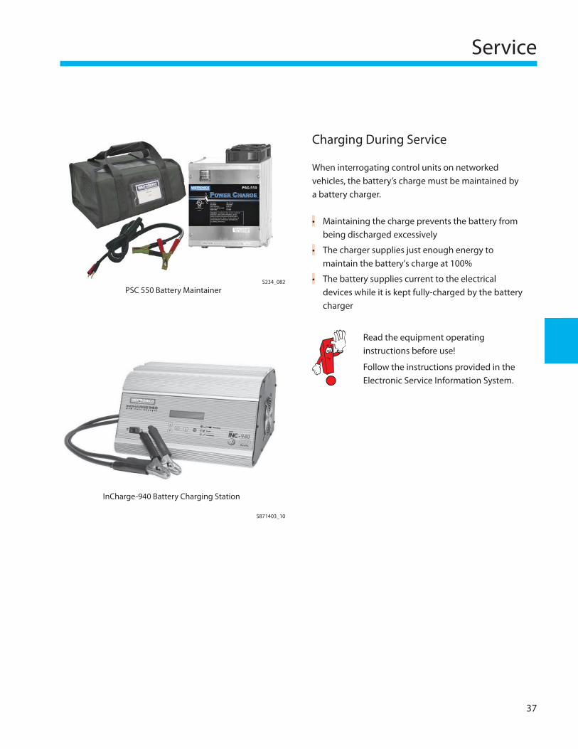
Charging During Service
When interrogating control units on networked vehicles, the battery’s charge must be maintained by a battery charger.
Maintaining the charge prevents the battery from being discharged excessively
The charger supplies just enough energy to maintain the battery’s charge at 100%
The battery supplies current to the electrical devices while it is kept fully-charged by the battery charger
Read the equipment operating instructions before use!
Follow the instructions provided in the Electronic Service Information System.
•
•
•PSC 550 Battery Maintainer
InCharge-940 Battery Charging Station
S871403_10
S234_082
38
Service
Discharge During Repair
A battery can discharge during repair with the ignition on.
This can occur due to the high current draw of headlights and other vehicle systems when the engine is not running.
Discharge can also occur with the ignition off and hood open.
Repair or diagnostic activity must be performed with a charged battery. For diagnostic checks and software updates, connect the PSC 550 battery maintainer to the battery posts in the engine compartment. If necessary, remove the headlight fuses to reduce battery discharge (this will cause systems faults that must be erased after the repair).
For extensive system checks that use more power, connect the INC-940 and select the MANUAL mode to maintain the battery charge.
Service
39
Jump Starting
Never jump start a frozen battery. There is a risk of an explosion!
A frozen battery MUST be replaced.
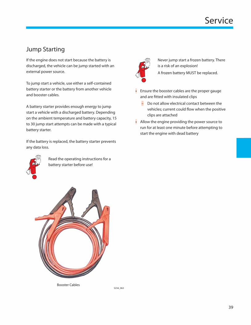
S234_063Booster Cables
If the engine does not start because the battery is discharged, the vehicle can be jump started with an external power source.
To jump start a vehicle, use either a self-contained battery starter or the battery from another vehicle and booster cables.
A battery starter provides enough energy to jump start a vehicle with a discharged battery. Depending on the ambient temperature and battery capacity, 15 to 30 jump start attempts can be made with a typical battery starter.
If the battery is replaced, the battery starter prevents any data loss.
Read the operating instructions for a battery starter before use!
Ensure the booster cables are the proper gauge and are fi tted with insulated clips
Do not allow electrical contact between the vehicles; current could fl ow when the positive clips are attached
Allow the engine providing the power source to run for at least one minute before attempting to start the engine with dead battery
•
–
•
40
Service
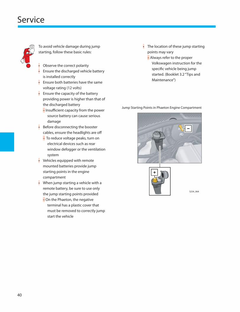
To avoid vehicle damage during jump starting, follow these basic rules:
Observe the correct polarityEnsure the discharged vehicle battery is installed correctlyEnsure both batteries have the same voltage rating (12 volts)Ensure the capacity of the battery providing power is higher than that of the discharged battery
Insuffi cient capacity from the power source battery can cause serious damage
Before disconnecting the booster cables, ensure the headlights are off
To reduce voltage peaks, turn on electrical devices such as rear window defogger or the ventilation system
Vehicles equipped with remote mounted batteries provide jump starting points in the engine compartmentWhen jump starting a vehicle with a remote battery, be sure to use only the jump starting points provided
On the Phaeton, the negative terminal has a plastic cover that must be removed to correctly jump start the vehicle
••
•
•
–
•
–
•
•
–
Jump Starting Points in Phaeton Engine Compartment
The location of these jump starting points may vary
Always refer to the proper Volkswagen instruction for the specifi c vehicle being jump started. (Booklet 3.2 “Tips and Maintenance”)
•
–
S234_064
Service
41
Battery Handling
Battery Replacement
The procedure for replacing a battery may diff er depending on the vehicle, however a number of important basic rules apply to any battery replacement.
Battery Removal
If the vehicle is equipped with an anti-theft coded radio, get the code before disconnecting the battery
Turn off the ignition
Open the heat insulating jacket (if equipped)
Remove the negative terminal
Remove the positive terminal
•
•
•
•
•
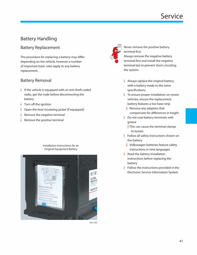
Installation Instructions for an Original Equipment Battery
Never remove the positive battery terminal fi rst. Always remove the negative battery terminal fi rst and install the negative terminal last to prevent short-circuiting the system.
Always replace the original battery with a battery made to the same specifi cationsTo ensure proper installation on newer vehicles, ensure the replacement battery features a low base strip
Remove any adapters that compensate for diff erences in height
Do not coat battery terminals with grease
This can cause the terminal clamps to loosen
Follow all safety instructions shown on the battery
Volkswagen batteries feature safety instructions in nine languages
Read the battery installation instructions before replacing the batteryFollow the instructions provided in the Electronic Service Information System
•
•
–
•
–
•
–
•
•
S234_065
42
Service
Battery Installation
To avoid damage to the battery housing, install the battery terminals by hand without using force
Tighten the battery positive terminal to the specifi ed torque provided in the Electronic Service Information System
After the positive terminal clamp has been tightened, install the negative terminal
On batteries equipped with a hose for central gas venting, ensure that the hose is not pinched or blocked in any way
On batteries not equipped with a hose for central gas venting, ensure that the vent opening at the top of the battery cover is not blocked
Check that the position of the battery is correct and, if necessary, check the groove in the base strip at the front or rear of the battery
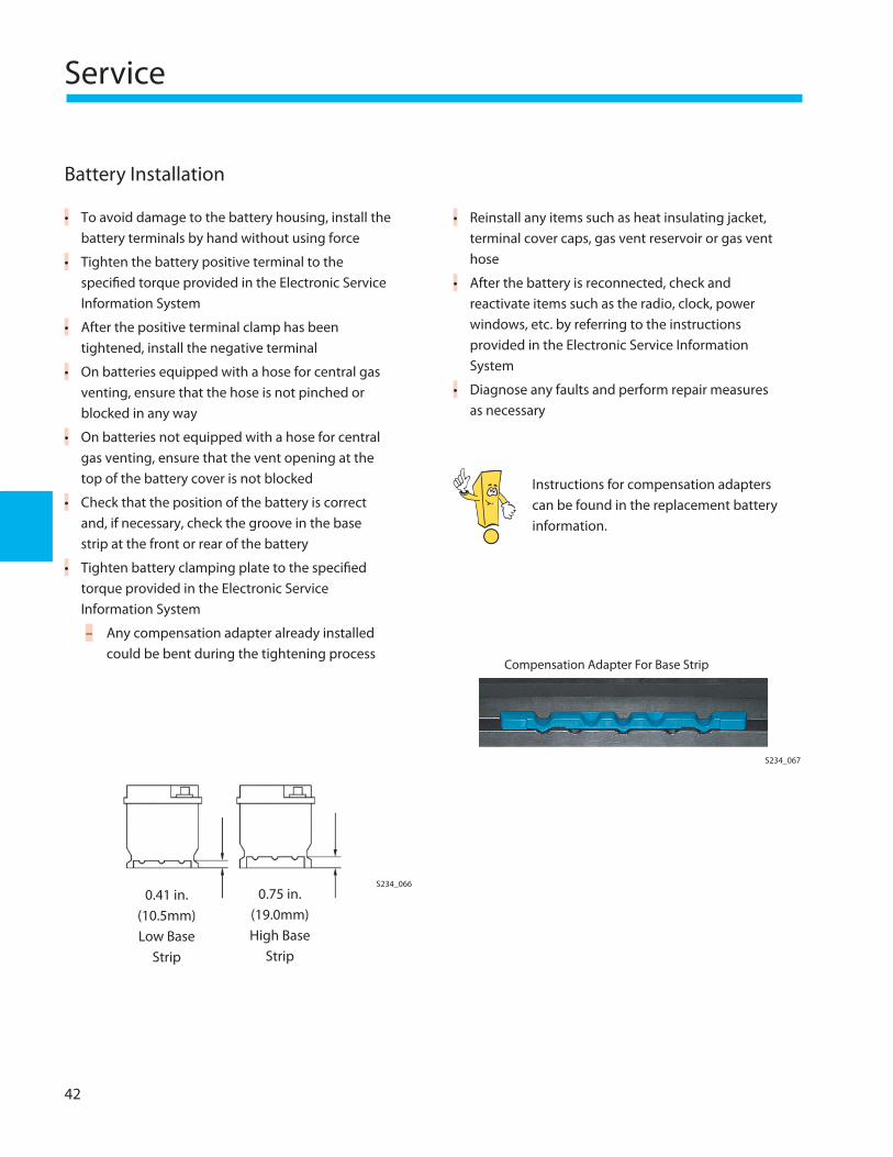
Tighten battery clamping plate to the specifi ed torque provided in the Electronic Service Information System
Any compensation adapter already installed could be bent during the tightening process
•
•
•
•
•
•
•
–
Reinstall any items such as heat insulating jacket, terminal cover caps, gas vent reservoir or gas vent hose
After the battery is reconnected, check and reactivate items such as the radio, clock, power windows, etc. by referring to the instructions provided in the Electronic Service Information System
Diagnose any faults and perform repair measures as necessary
Instructions for compensation adapters can be found in the replacement battery information.
•
•
•
Compensation Adapter For Base Strip
S234_067
S234_0660.41 in.
(10.5mm) Low Base
Strip
0.75 in. (19.0mm) High Base
Strip
Service
43
Storage and Transportation
Storage
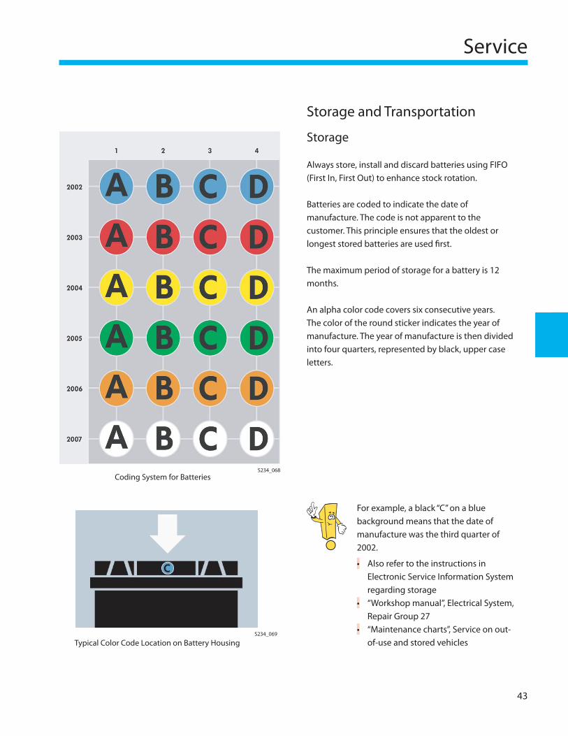
Always store, install and discard batteries using FIFO (First In, First Out) to enhance stock rotation.
Batteries are coded to indicate the date of manufacture. The code is not apparent to the customer. This principle ensures that the oldest or longest stored batteries are used fi rst.
The maximum period of storage for a battery is 12 months.
An alpha color code covers six consecutive years. The color of the round sticker indicates the year of manufacture. The year of manufacture is then divided into four quarters, represented by black, upper case letters.
Coding System for BatteriesS234_068
Typical Color Code Location on Battery HousingS234_069
For example, a black “C” on a blue background means that the date of manufacture was the third quarter of 2002.
Also refer to the instructions in Electronic Service Information System regarding storage“Workshop manual”, Electrical System, Repair Group 27“Maintenance charts”, Service on out-of-use and stored vehicles
•
•
•
44
Service
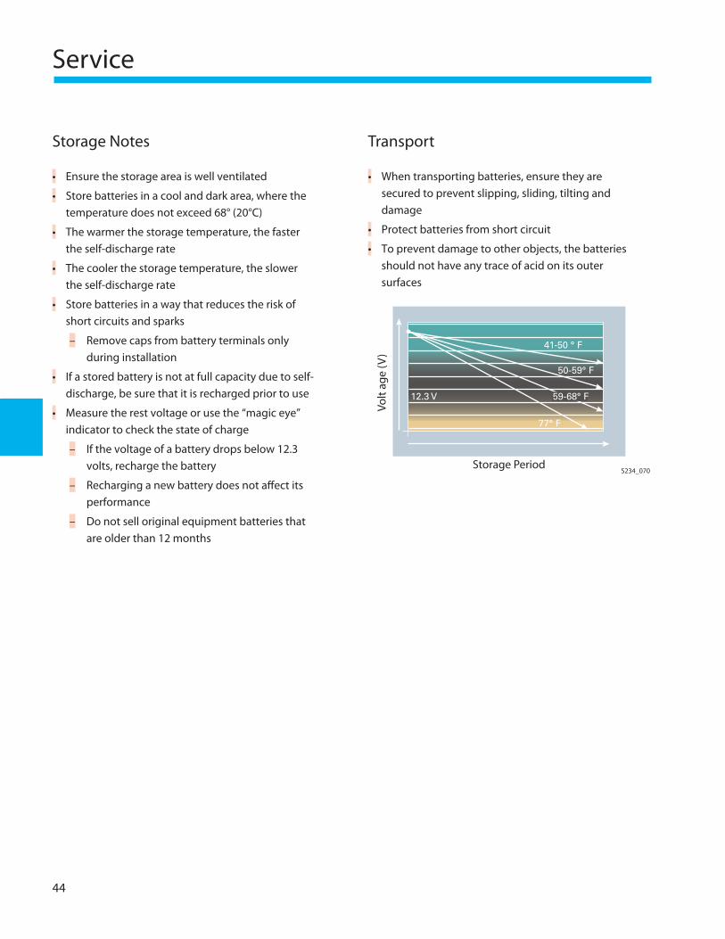
Storage Notes
Ensure the storage area is well ventilated
Store batteries in a cool and dark area, where the temperature does not exceed 68° (20°C)
The warmer the storage temperature, the faster the self-discharge rate
The cooler the storage temperature, the slower the self-discharge rate
Store batteries in a way that reduces the risk of short circuits and sparks
Remove caps from battery terminals only during installation
If a stored battery is not at full capacity due to self-discharge, be sure that it is recharged prior to use
Measure the rest voltage or use the “magic eye” indicator to check the state of charge
If the voltage of a battery drops below 12.3 volts, recharge the battery
Recharging a new battery does not aff ect its performance
Do not sell original equipment batteries that are older than 12 months
•
•
•
•
•
–
•
•
–
–
–
Transport
When transporting batteries, ensure they are secured to prevent slipping, sliding, tilting and damage
Protect batteries from short circuit
To prevent damage to other objects, the batteries should not have any trace of acid on its outer surfaces
•
•
•
S234_070Storage Period
Volt
age
(V)
41-50 ° F
50-59° F
77° F
59-68° F 12.3 V
Service
45
Battery Handling Cautions
General Cautions
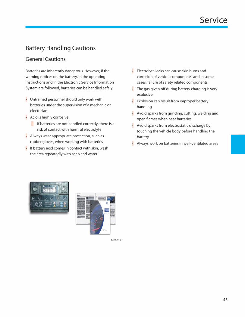
Batteries are inherently dangerous. However, if the warning notices on the battery, in the operating instructions and in the Electronic Service Information System are followed, batteries can be handled safely.
Untrained personnel should only work with batteries under the supervision of a mechanic or electrician
Acid is highly corrosive
If batteries are not handled correctly, there is a risk of contact with harmful electrolyte
Always wear appropriate protection, such as rubber gloves, when working with batteries
If battery acid comes in contact with skin, wash the area repeatedly with soap and water
•
•
–
•
•
S234_072
Electrolyte leaks can cause skin burns and corrosion of vehicle components, and in some cases, failure of safety related components
The gas given off during battery charging is very explosive
Explosion can result from improper battery handling
Avoid sparks from grinding, cutting, welding and open fl ames when near batteries
Avoid sparks from electrostatic discharge by touching the vehicle body before handling the battery
Always work on batteries in well-ventilated areas
•
•
•
•
•
•
46
Service
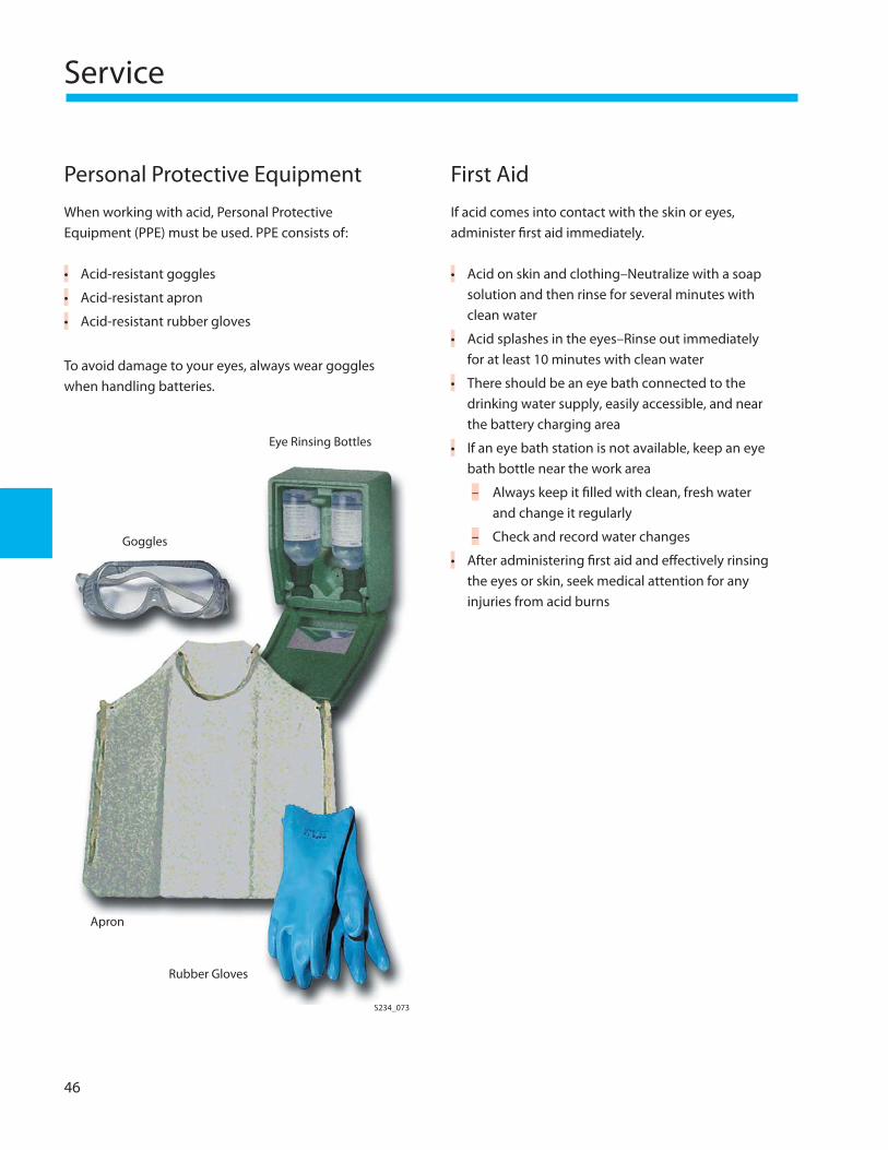
Personal Protective Equipment
When working with acid, Personal Protective Equipment (PPE) must be used. PPE consists of:
Acid-resistant goggles
Acid-resistant apron
Acid-resistant rubber gloves
To avoid damage to your eyes, always wear goggles when handling batteries.
•
•
•
S234_073
Eye Rinsing Bottles
First Aid
If acid comes into contact with the skin or eyes, administer fi rst aid immediately.
Acid on skin and clothing–Neutralize with a soap solution and then rinse for several minutes with clean water
Acid splashes in the eyes–Rinse out immediately for at least 10 minutes with clean water
There should be an eye bath connected to the drinking water supply, easily accessible, and near the battery charging area
If an eye bath station is not available, keep an eye bath bottle near the work area
Always keep it fi lled with clean, fresh water and change it regularly
Check and record water changes
After administering fi rst aid and eff ectively rinsing the eyes or skin, seek medical attention for any injuries from acid burns
•
•
•
•
–
–
•Goggles
Apron
Rubber Gloves
Service
47
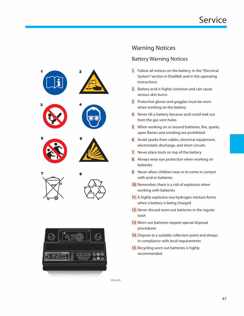
Warning Notices
Battery Warning Notices
Follow all notices on the battery, in the “Electrical System” section in ElsaWeb and in the operating instructions
Battery acid is highly corrosive and can cause serious skin burns
Protective gloves and goggles must be worn when working on the battery
Never tilt a battery because acid could leak out from the gas vent holes
When working on or around batteries, fi re, sparks, open fl ames and smoking are prohibited
Avoid sparks from cables, electrical equipment, electrostatic discharge, and short circuits
Never place tools on top of the battery
Always wear eye protection when working on batteries
Never allow children near or to come in contact with acid or batteries
Remember, there is a risk of explosion when working with batteries
A highly explosive oxy-hydrogen mixture forms when a battery is being charged
Never discard worn out batteries in the regular trash
Worn out batteries require special disposal procedures
Dispose at a suitable collection point and always in compliance with local requirements
Recycling worn out batteries is highly recommended
1.
2.
3.
4.
5.
6.
7.
8.
9.
10.
11.
12.
13.
14.
15.
S234_074

48
Notes
Glossary
49
Accumulator:Stores or collects energy for use at a later time.
Acid Level:Level of electrolyte in wet-type batteries, same as electrolyte level.
Generator:A unit driven by the vehicle engine which generates energy for the electrical system and charges the battery.
Ampere (A):Unit of measurement for amount of current fl owing in a circuit.
Ampere Hour (Ah):Product of current multiplied by time.
Battery:Stores energy in the same way as accumulator.
Battery Terminals:Positive and negative connection points on a battery that connect it to the generator and the vehicle electrical system.
Battery Terminal Clamps:Clamps that connect wires to battery terminals.
Capacity:Amount of current that can be drawn from a battery, measured in ampere hours (Ah).
Cell Sealing Plug:The cell sealing plug seals the cell openings in the cover.
Charge Current:Current that charges the battery.
Charge State:The degree to which the battery is charged.
Charge Voltage:Voltage during charging.
Charging:Conversion of electrical energy to chemical energy by means of a current fl owing from an generator.
Cold Cranking Amps (CCA, EN, DIN):Measures the discharge load, in amps, that a battery can supply for a specifi ed period of time at a specifi ed temperature while maintaining a minimum specifi ed voltage.
Two cold testing currents are shown on a battery. For example on a 60 Ah battery: 480 A EN and 280 A DIN.
The battery should be able to deliver each one of these currents for a diff erent duration at 0°F (-18°C), without the battery voltage falling below a given value.
Example for 60 Ah battery: At a load of 480 A at 0°F (-18°C) following the EN standard, the battery voltage should not drop below 7.5 volts after 10 seconds. After 10 seconds, the battery is placed under a load of 280 A at 0°F (-18°C). After 133 seconds under load with the DIN current, the battery voltage should not drop below 6 volts.
CoverThe cover is permanently attached to the housing by a plastic weld.
50
Glossary
Current Charge FactorRatio of current required to fully charge a battery to current draw.
Deep Discharge:Complete discharge of a battery. A battery is deeply discharged if the acid density is below 1.14 g/cm3 and the rest voltage is below 11.9 volts.
DIN:(Deutsches Institut fur Normung) DIN is a non-governmental organization established to promote the development of standardization and related activities in Germany and related markets.Over 12,000 DIN standards cover a wide range of topics including: physical quantities and units, fasteners, water analysis, building and civil engineering, materials testing, steel pipes, machine tools, twist drills, roller and ball bearings, and process engineering.
Discharging:Conversion of chemical energy to electrical energy (current fl ows in the opposite direction of charging).
Distilled Water:Used to replenish electrolyte that diminishes from gas generation and evaporation. Purity regulations must be followed (see VDE 0510). Use only distilled water! Never use tap water.
Electrolyte:Liquid conductor consisting of a sulfuric acid and water solution that connects battery plates.
Electrolyte Level or Acid Level:Fluid level of electrolyte in wet-type batteries.
EN:Abbreviation for “European Standard”.
End Discharge Voltage:Voltage level below which voltage should not drop from current draw. When end discharge voltage is reached, discharge stops.
Full Charge:Charge with complete chemical conversion. Lead-acid batteries are fully charged when acid density and voltage come to rest at the end of the charge process.
Gas Formation Voltage:Charge voltage above which a battery begins to generate large quantities of gas.
Gas Generation:Oxy-hydrogen gas formed during charging from the breakdown of water in the electrolyte.
Gas Venting/Gas Discharge:The oxy-hydrogen gas that is formed during charging is vented through a hose to a non-hazardous location.
Grid:The carrier of the active material in a battery.
Housing:Holds the multiple cells of a battery and is separated by partitions.
Hydrometer:A device that measures the specifi c gravity of the electrolyte.
Lead-Acid Battery:Consists of lead dioxide (positive), lead (negative) in a charged state, and electrolyte (weakened sulfuric acid).
Glossary
51
Mass, Active:Plates (electrodes) that are subjected to chemical reactions from current fl ow.
Negative Plate:Consists of lead (Pb) on a charged battery.
Nominal Figures:Fixed voltage, capacity, density, temperature values, etc. as specifi ed in DIN 40729 and DIN 72311 standards.
Example: The nominal voltage of lead-acid battery is the product of the number of cells connected in series (6 cells in 12 volt battery) and the nominal voltage of the lead-acid cell (2.0 volts).
Nominal capacity is the capacity of a battery to return nominal current after 20 hours of discharge at a nominal temperature and a nominal density with a nominal level of electrolyte, without falling below a specifi ed minimum voltage.
Oxy-Hydrogen Gas:Explosive mixture of hydrogen and oxygen.
Plate Block:Combination of positive and negative plate sets within one cell, including separators.
Plate Connector:Connection between plates of the same polarity in one cell.
Positive Plate:Consists of lead dioxide (PbO2) on a charged battery.
Rapid Charge:Fast charging of the battery using a high charge current. Rapid charging only partially charges the battery. Batteries should not be charged in this manner. Rapid charging can damage a battery.
Rectifi er:Changes alternating current into direct current (AC to DC).
Rest Voltage:Voltage at the terminals of a battery when no charging or discharging is taking place.
SAE:Society of Automotive Engineers
Sealing Plug:Used to seal the central gas venting system in the battery cover. The sealing plug must be placed on only one side of wet-type replacement batteries. (Do not confuse with cell sealing plugs!)
Self-Discharge:Discharge from chemical reactions in the battery without an electrical load being placed on the battery.
Separator:Separating material between battery plates of diff erent polarity. Polyethylene for wet batteries, glass mat for AGM batteries.
Series Connection:Cells connected one after another, positive to negative, such as six lead-acid cells to form a 12 volt battery.
52
Glossary
Specifi c Gravity:The weight of battery electrolyte (sulfuric acid) solution in reference to distilled water when water has a value of 1.0. Also referred to as acid density and density. Specifi c gravity is measured using a hydrometer.
Starter Battery:Serves mainly as power source for engine starting and for ignition.
Start Output:Power required by the starter to turn over the engine.
Sulfating:Conversion of lead in battery to crystalline lead sulfate.
Terminal Voltage:Voltage between the two terminals of a battery.
Useful Lifespan:Period of time from new until the battery is no longer usable.
Volt (V):Unit of measurement for voltage.
Water:Used in this SSP to refer to distilled water.

Knowledge Assessment
53
An on-line Knowledge Assessment (exam) is available for this Self-Study Program.
The Knowledge Assessment may or may not be required for Certifi cation.
You can fi nd this Knowledge Assessment at:
www.vwwebsource.com
For Assistance, please call:
Volkswagen Academy
Certifi cation Program Headquarters
1 – 877 – VW – CERT – 5
(1 – 877 – 892 – 3785)
(8:00 a.m. to 8:00 p.m. EST)
Or, E-Mail:
Volkswagen of America, Inc.3800 Hamlin RoadAuburn Hill, MI 48326Printed in the U.S.A.January 2007
873603