Embed Size (px)
Citation preview
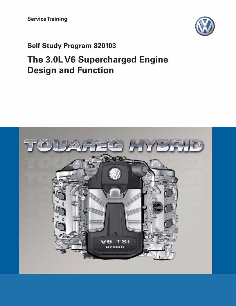
Service Training
Self Study Program 820103
The 3.0L V6 Supercharged Engine Design and Function
Volkswagen Group of America, Inc.Volkswagen AcademyPrinted in U.S.A.Printed 10/2010
Course Number 820103
©2010 Volkswagen Group of America, Inc.
All rights reserved. All information contained in this manual is based on the latest information available at the time of printing and is subject to the copyright and other intellectual property rights of Volkswagen Group of America, Inc., its affi liated companies and its licensors. All rights are reserved to make changes at any time without notice. No part of this document may be reproduced, stored in a retrieval system, or transmitted in any form or by any means, electronic, mechanical, photocopying, recording or otherwise, nor may these materials be modifi ed or reposted to other sites without the prior expressed written permission of the publisher.
All requests for permission to copy and redistribute information should be referred to Volkswagen Group of America, Inc.
Always check Technical Bulletins and the latest electronic repair information for information that may supersede any information included in this booklet.
Trademarks: All brand names and product names used in this manual are trade names, service marks, trademarks, or registered trademarks; and are the property of their respective owners.
iii
Contents
This Self-Study Program provides information regarding the design and function of new models.This Self-Study Program is not a Repair Manual.
This information will not be updated.For maintenance and repair procedures, always refer to the latest electronic service information.
Note Important!
Introduction . . . . . . . . . . . . . . . . . . . . . . . . . . . . . . . . . . . . . . . . . . . . . . . . 1
Engine Components . . . . . . . . . . . . . . . . . . . . . . . . . . . . . . . . . . . . . . . . . 5
Air Supply . . . . . . . . . . . . . . . . . . . . . . . . . . . . . . . . . . . . . . . . . . . . . . . . . 11
Cooling System . . . . . . . . . . . . . . . . . . . . . . . . . . . . . . . . . . . . . . . . . . . . 28
Exhaust Gas Treatment . . . . . . . . . . . . . . . . . . . . . . . . . . . . . . . . . . . . . . 32
Oil Supply . . . . . . . . . . . . . . . . . . . . . . . . . . . . . . . . . . . . . . . . . . . . . . . . . 34
Fuel System . . . . . . . . . . . . . . . . . . . . . . . . . . . . . . . . . . . . . . . . . . . . . . . 42
Engine Management . . . . . . . . . . . . . . . . . . . . . . . . . . . . . . . . . . . . . . . . 45
Service . . . . . . . . . . . . . . . . . . . . . . . . . . . . . . . . . . . . . . . . . . . . . . . . . . . 46
Glossary . . . . . . . . . . . . . . . . . . . . . . . . . . . . . . . . . . . . . . . . . . . . . . . . . . 48
Knowledge Assessment . . . . . . . . . . . . . . . . . . . . . . . . . . . . . . . . . . . . . 50
Page intentionally left blank
1
Introduction
S452_002
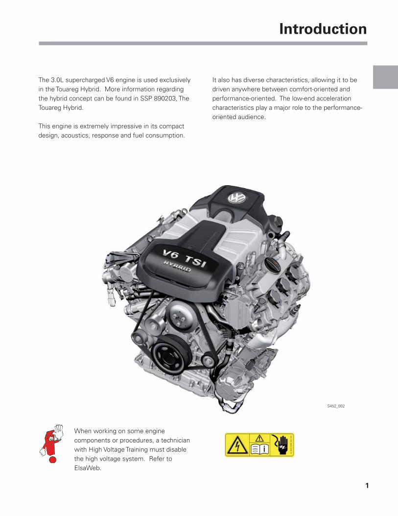
The 3.0L supercharged V6 engine is used exclusively in the Touareg Hybrid. More information regarding the hybrid concept can be found in SSP 890203, The Touareg Hybrid.
This engine is extremely impressive in its compact design, acoustics, response and fuel consumption.
It also has diverse characteristics, allowing it to be driven anywhere between comfort-oriented and performance-oriented. The low-end acceleration characteristics play a major role to the performance-oriented audience.
When working on some engine components or procedures, a technician with High Voltage Training must disable the high voltage system. Refer to ElsaWeb.
2
Introduction
S452_010
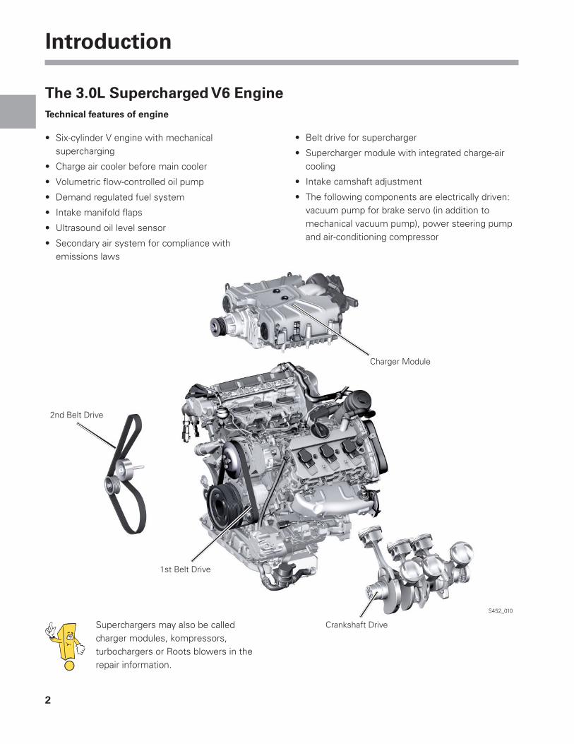
Superchargers may also be called charger modules, kompressors, turbochargers or Roots blowers in the repair information.
The 3.0L Supercharged V6 EngineTechnical features of engine
• Six-cylinder V engine with mechanical supercharging
• Charge air cooler before main cooler
• Volumetric fl ow-controlled oil pump
• Demand regulated fuel system
• Intake manifold fl aps
• Ultrasound oil level sensor
• Secondary air system for compliance with emissions laws
• Belt drive for supercharger
• Supercharger module with integrated charge-air cooling
• Intake camshaft adjustment
• The following components are electrically driven: vacuum pump for brake servo (in addition to mechanical vacuum pump), power steering pump and air-conditioning compressor
Charger Module
Crankshaft Drive
1st Belt Drive
2nd Belt Drive
3
Introduction
1000 2000 3000 4000 5000 6000 rpm75
150
225
300
375
450
lb/ft hp
400
335
270
200
135
70
0
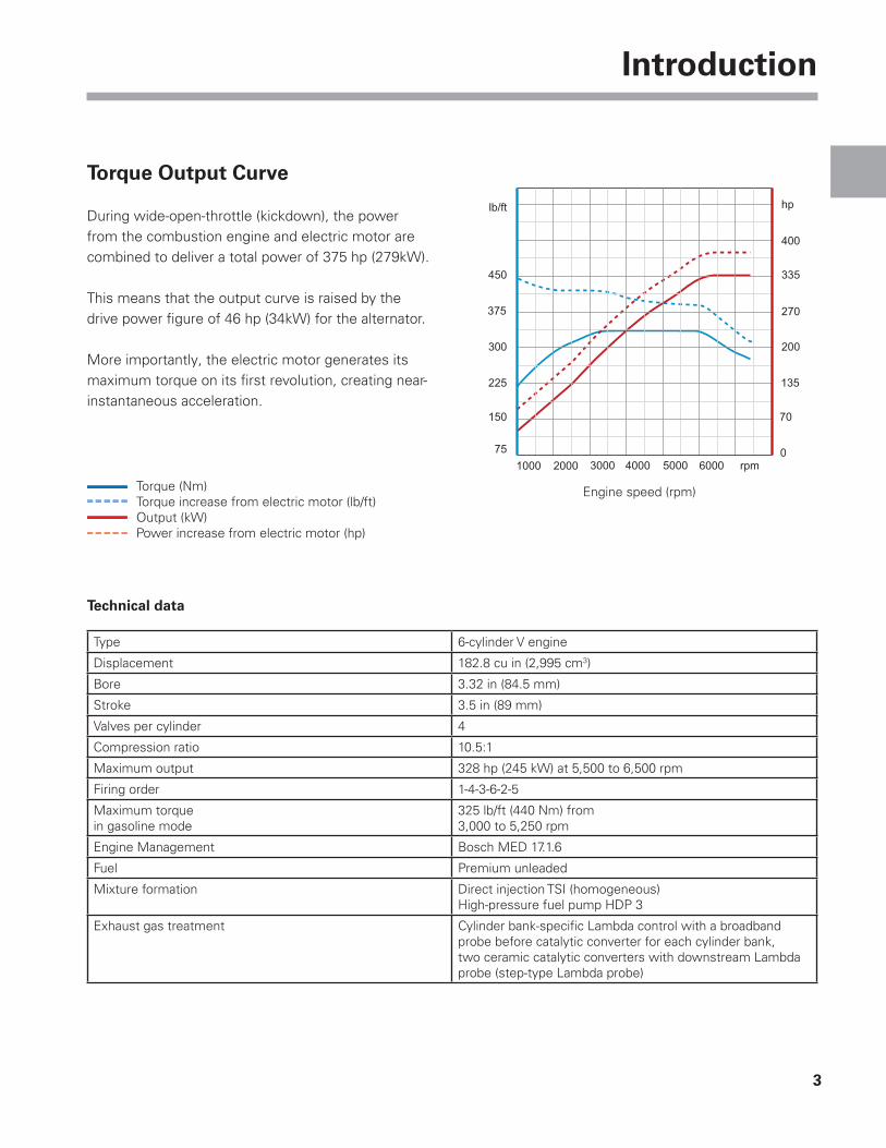
Torque Output Curve
During wide-open-throttle (kickdown), the power from the combustion engine and electric motor are combined to deliver a total power of 375 hp (279kW).
This means that the output curve is raised by the drive power fi gure of 46 hp (34kW) for the alternator.
More importantly, the electric motor generates its maximum torque on its fi rst revolution, creating near-instantaneous acceleration.
Technical data
Type 6-cylinder V engine
Displacement 182.8 cu in (2,995 cm3)
Bore 3.32 in (84.5 mm)
Stroke 3.5 in (89 mm)
Valves per cylinder 4
Compression ratio 10.5:1
Maximum output 328 hp (245 kW) at 5,500 to 6,500 rpm
Firing order 1-4-3-6-2-5
Maximum torquein gasoline mode
325 lb/ft (440 Nm) from 3,000 to 5,250 rpm
Engine Management Bosch MED 17.1.6
Fuel Premium unleaded
Mixture formation Direct injection TSI (homogeneous)High-pressure fuel pump HDP 3
Exhaust gas treatment Cylinder bank-specifi c Lambda control with a broadband probe before catalytic converter for each cylinder bank, two ceramic catalytic converters with downstream Lambda probe (step-type Lambda probe)
Engine speed (rpm)Torque (Nm)Torque increase from electric motor (lb/ft)Output (kW)Power increase from electric motor (hp)
4
Introduction
S452_004
S452_005
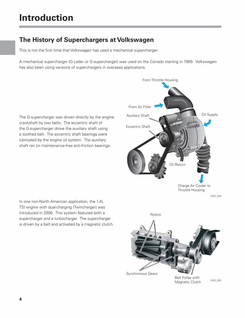
The History of Superchargers at Volkswagen
This is not the fi rst time that Volkswagen has used a mechanical supercharger.
A mechanical supercharger (G-Lader or G-supercharger) was used on the Corrado starting in 1989. Volkswagen has also been using versions of superchargers in overseas applications.
The G-supercharger was driven directly by the engine crankshaft by two belts. The eccentric shaft of the G-supercharger drove the auxiliary shaft using a toothed belt. The eccentric shaft bearings were lubricated by the engine oil system. The auxiliary shaft ran on maintenance-free anti-friction bearings.
In one non-North American application, the 1.4L TSI engine with dual-charging (Twincharger) was introduced in 2006. This system featured both a supercharger and a turbocharger. The supercharger is driven by a belt and activated by a magnetic clutch.
Charge Air Cooler toThrottle Housing
Oil Return
Eccentric Shaft
Auxiliary Shaft
From Air Filter
From Throttle Housing
Belt Pulley withMagnetic Clutch
Synchronous Gears
Rotors
Oil Supply
5
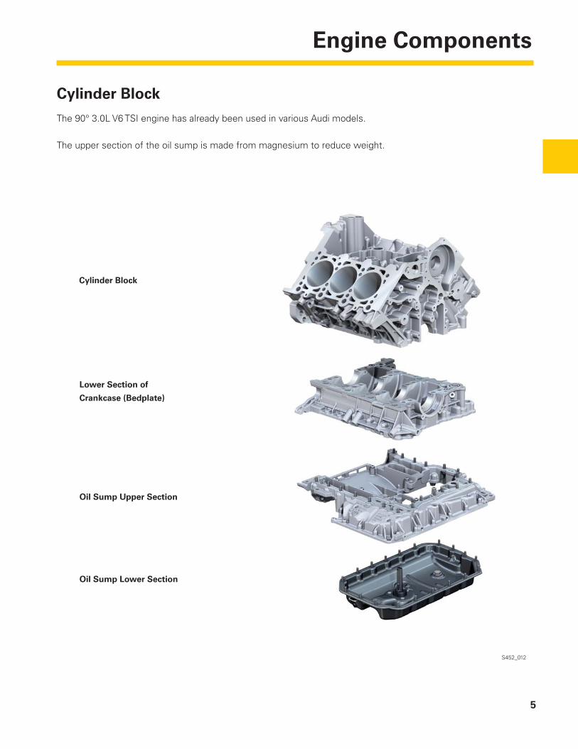
Engine Components
S452_012
Cylinder Block
The 90° 3.0L V6 TSI engine has already been used in various Audi models.
The upper section of the oil sump is made from magnesium to reduce weight.
Oil Sump Lower Section
Oil Sump Upper Section
Lower Section of
Crankcase (Bedplate)
Cylinder Block
6
Engine Components
S452_014
S452_013
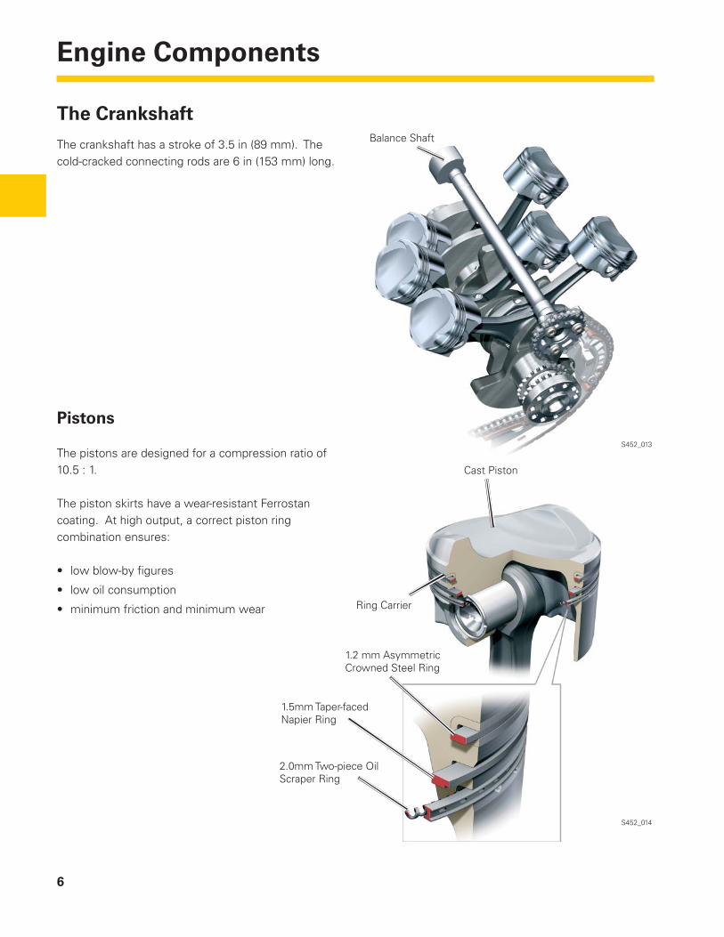
The Crankshaft
The crankshaft has a stroke of 3.5 in (89 mm). The cold-cracked connecting rods are 6 in (153 mm) long.
Balance Shaft
Pistons
The pistons are designed for a compression ratio of 10.5 : 1.
The piston skirts have a wear-resistant Ferrostan coating. At high output, a correct piston ring combination ensures:
• low blow-by fi gures
• low oil consumption
• minimum friction and minimum wear
2.0mm Two-piece OilScraper Ring
1.5mm Taper-facedNapier Ring
1.2 mm AsymmetricCrowned Steel Ring
Ring Carrier
Cast Piston
7
Engine Components
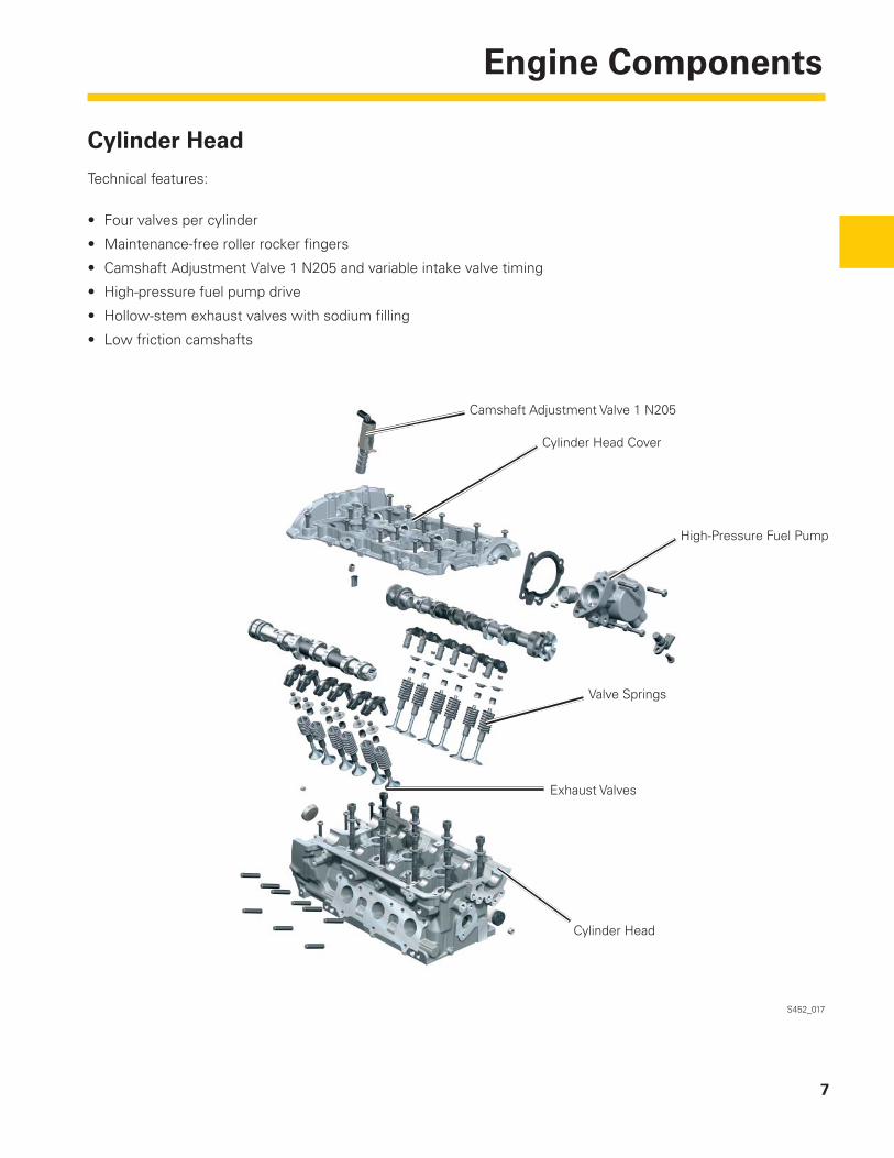
Cylinder Head
Technical features:
• Four valves per cylinder
• Maintenance-free roller rocker fi ngers
• Camshaft Adjustment Valve 1 N205 and variable intake valve timing
• High-pressure fuel pump drive
• Hollow-stem exhaust valves with sodium fi lling
• Low friction camshafts
S452_017
Camshaft Adjustment Valve 1 N205
Cylinder Head Cover
High-Pressure Fuel Pump
Valve Springs
Exhaust Valves
Cylinder Head
8
Engine Components
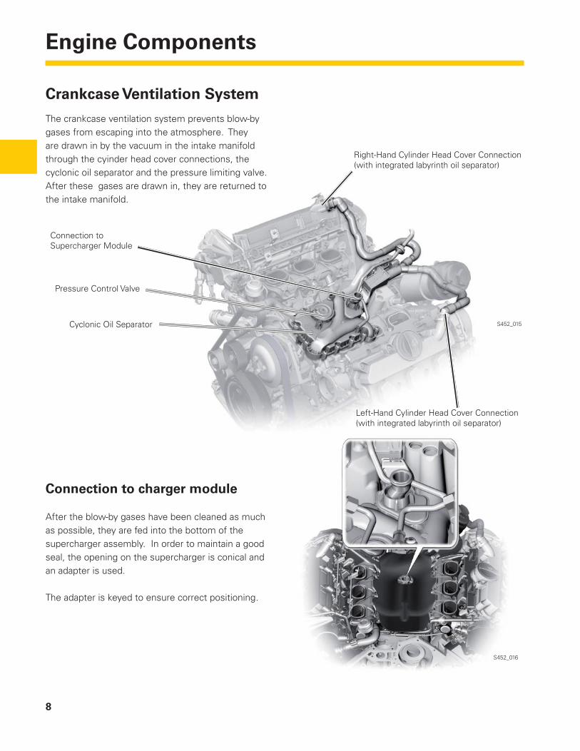
Crankcase Ventilation System
The crankcase ventilation system prevents blow-by gases from escaping into the atmosphere. They are drawn in by the vacuum in the intake manifold through the cyinder head cover connections, the cyclonic oil separator and the pressure limiting valve. After these gases are drawn in, they are returned to the intake manifold.
S452_015
S452_016
Connection to charger module
After the blow-by gases have been cleaned as much as possible, they are fed into the bottom of the supercharger assembly. In order to maintain a good seal, the opening on the supercharger is conical and an adapter is used.
The adapter is keyed to ensure correct positioning.
Left-Hand Cylinder Head Cover Connection(with integrated labyrinth oil separator)
Cyclonic Oil Separator
Pressure Control Valve
Connection to Supercharger Module
Right-Hand Cylinder Head Cover Connection(with integrated labyrinth oil separator)
9
Engine Components
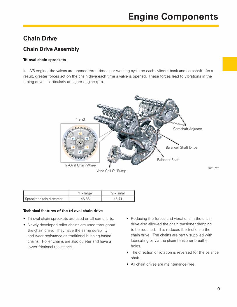
Chain Drive
Chain Drive Assembly
Tri-oval chain sprockets
In a V6 engine, the valves are opened three times per working cycle on each cylinder bank and camshaft. As a result, greater forces act on the chain drive each time a valve is opened. These forces lead to vibrations in the timing drive – particularly at higher engine rpm.
S452_077
Technical features of the tri-oval chain drive
• Tri-oval chain sprockets are used on all camshafts.
• Newly developed roller chains are used throughout the chain drive. They have the same durability and wear resistance as traditional bushing-based chains. Roller chains are also quieter and have a lower frictional resistance.
• Reducing the forces and vibrations in the chain drive also allowed the chain tensioner damping to be reduced. This reduces the friction in the chain drive. The chains are partly supplied with lubricating oil via the chain tensioner breather holes.
• The direction of rotation is reversed for the balance shaft.
• All chain drives are maintenance-free.
Vane Cell Oil Pump
Balancer Shaft
Balancer Shaft Drive
Camshaft Adjuster
r1 – large r2 – small
Sprocket circle diameter 46.86 45.71
r1 > r2
Tri-Oval Chain Wheel
10
Engine Components
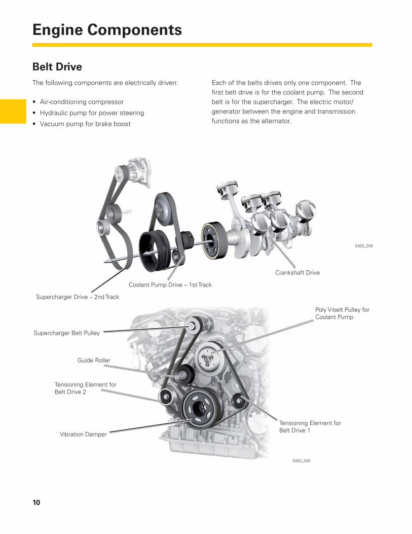
Belt DriveThe following components are electrically driven:
• Air-conditioning compressor
• Hydraulic pump for power steering
• Vacuum pump for brake boost
Each of the belts drives only one component. The fi rst belt drive is for the coolant pump. The second belt is for the supercharger. The electric motor/generator between the engine and transmission functions as the alternator.
S452_020
S452_019
Coolant Pump Drive – 1st Track
Supercharger Drive – 2nd Track
Crankshaft Drive
Supercharger Belt Pulley
Vibration Damper
Tensioning Element forBelt Drive 2
Guide Roller
Poly V-belt Pulley forCoolant Pump
Tensioning Element forBelt Drive 1
11
Air Supply
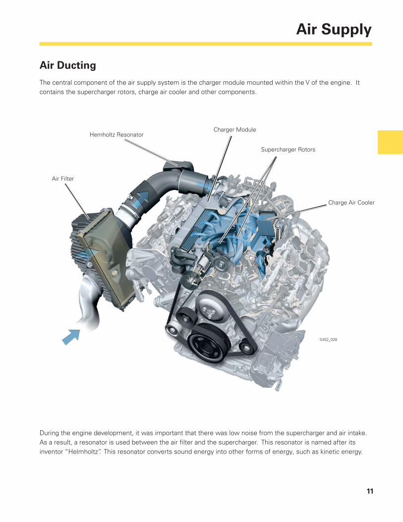
Air Ducting
The central component of the air supply system is the charger module mounted within the V of the engine. It contains the supercharger rotors, charge air cooler and other components.
S452_028
During the engine development, it was important that there was low noise from the supercharger and air intake. As a result, a resonator is used between the air fi lter and the supercharger. This resonator is named after its inventor “Helmholtz”. This resonator converts sound energy into other forms of energy, such as kinetic energy.
Charge Air Cooler
Supercharger Rotors
Charger ModuleHemholtz Resonator
Air Filter
12
Air Supply
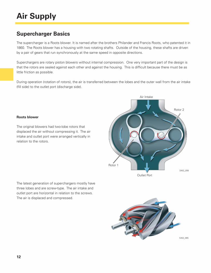
Supercharger Basics
The supercharger is a Roots blower. It is named after the brothers Philander and Francis Roots, who patented it in 1860. The Roots blower has a housing with two rotating shafts. Outside of the housing, these shafts are driven by a pair of gears that run synchronously at the same speed in opposite directions.
Superchargers are rotary piston blowers without internal compression. One very important part of the design is that the rotors are sealed against each other and against the housing. This is diffi cult because there must be as little friction as possible.
During operation (rotation of rotors), the air is transferred between the lobes and the outer wall from the air intake (fi ll side) to the outlet port (discharge side).
Roots blower
The original blowers had two-lobe rotors that displaced the air without compressing it. The air intake and outlet port were arranged vertically in relation to the rotors.
The latest generation of superchargers mostly have three lobes and are screw-type. The air intake and outlet port are horizontal in relation to the screws. The air is displaced and compressed.
S452_008
S452_065
Outlet Port
Rotor 1
Air Intake
Rotor 2
13
Air Supply
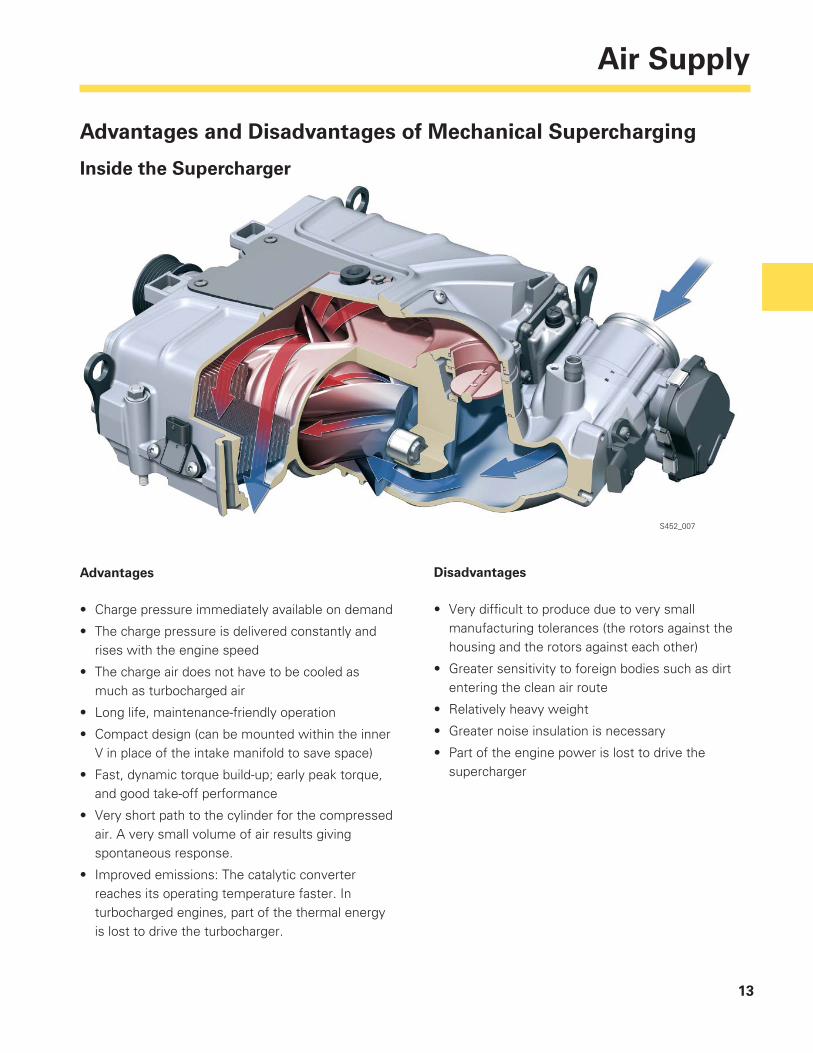
Advantages and Disadvantages of Mechanical Supercharging
Inside the Supercharger
S452_007
Advantages
• Charge pressure immediately available on demand
• The charge pressure is delivered constantly and rises with the engine speed
• The charge air does not have to be cooled as much as turbocharged air
• Long life, maintenance-friendly operation
• Compact design (can be mounted within the inner V in place of the intake manifold to save space)
• Fast, dynamic torque build-up; early peak torque, and good take-off performance
• Very short path to the cylinder for the compressed air. A very small volume of air results giving spontaneous response.
• Improved emissions: The catalytic converter reaches its operating temperature faster. In turbocharged engines, part of the thermal energy is lost to drive the turbocharger.
Disadvantages
• Very diffi cult to produce due to very small manufacturing tolerances (the rotors against the housing and the rotors against each other)
• Greater sensitivity to foreign bodies such as dirt entering the clean air route
• Relatively heavy weight
• Greater noise insulation is necessary
• Part of the engine power is lost to drive the supercharger
14
Air Supply
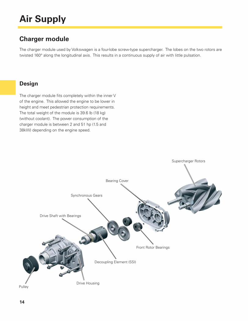
Charger module
The charger module used by Volkswagen is a four-lobe screw-type supercharger. The lobes on the two rotors are twisted 160° along the longitudinal axis. This results in a continuous supply of air with little pulsation.
Design
The charger module fi ts completely within the inner V of the engine. This allowed the engine to be lower in height and meet pedestrian protection requirements. The total weight of the module is 39.6 lb (18 kg) (without coolant). The power consumption of the charger module is between 2 and 51 hp (1.5 and 38kW) depending on the engine speed.
PulleyDrive Housing
Decoupling Element (SSI)
Drive Shaft with Bearings
Bearing Cover
Front Rotor Bearings
Synchronous Gears
Supercharger Rotors
15
Air Supply
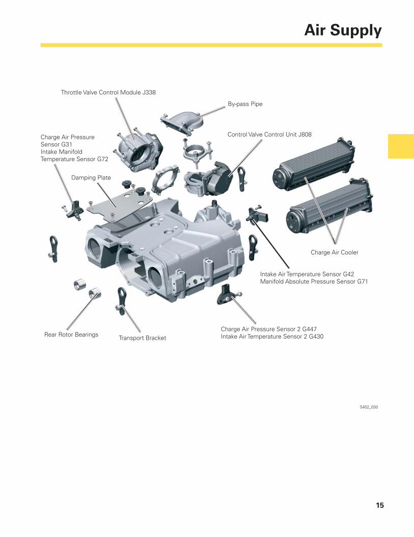
S452_030
Charge Air Pressure Sensor G31Intake Manifold Temperature Sensor G72
Damping Plate
Rear Rotor Bearings Transport BracketCharge Air Pressure Sensor 2 G447Intake Air Temperature Sensor 2 G430
Intake Air Temperature Sensor G42Manifold Absolute Pressure Sensor G71
Charge Air Cooler
Control Valve Control Unit J808
By-pass Pipe
Throttle Valve Control Module J338
16
Air Supply
S452_031
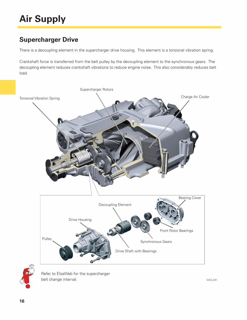
Supercharger Drive
There is a decoupling element in the supercharger drive housing. This element is a torsional vibration spring.
Crankshaft force is transferred from the belt pulley by the decoupling element to the synchronous gears. The decoupling element reduces crankshaft vibrations to reduce engine noise. This also considerably reduces belt load.
Supercharger Rotors
Charge Air CoolerTorsional Vibration Spring
Refer to ElsaWeb for the supercharger belt change interval.
Decoupling Element
Bearing Cover
Front Rotor Bearings
Synchronous Gears
Drive Housing
Drive Shaft with Bearings
Pulley
17
Air Supply
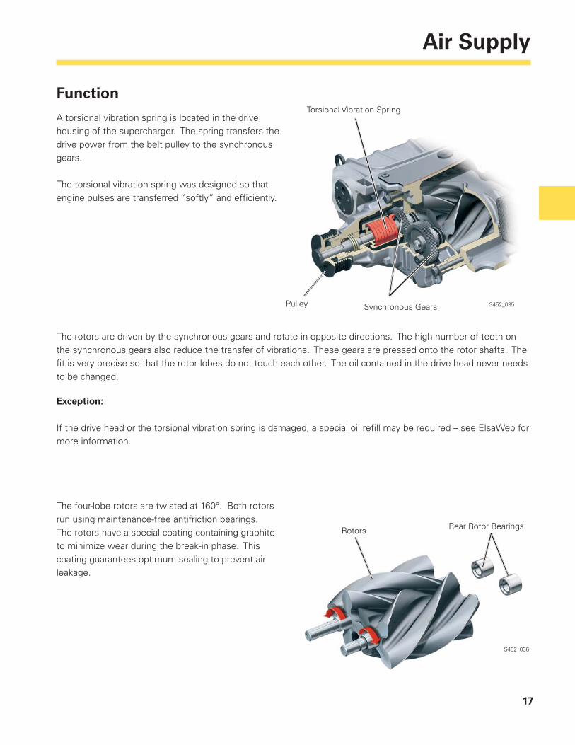
Function
A torsional vibration spring is located in the drive housing of the supercharger. The spring transfers the drive power from the belt pulley to the synchronous gears.
The torsional vibration spring was designed so that engine pulses are transferred “softly” and effi ciently.
The rotors are driven by the synchronous gears and rotate in opposite directions. The high number of teeth on the synchronous gears also reduce the transfer of vibrations. These gears are pressed onto the rotor shafts. The fi t is very precise so that the rotor lobes do not touch each other. The oil contained in the drive head never needs to be changed.
Exception:
If the drive head or the torsional vibration spring is damaged, a special oil refi ll may be required – see ElsaWeb for more information.
The four-lobe rotors are twisted at 160°. Both rotors run using maintenance-free antifriction bearings. The rotors have a special coating containing graphite to minimize wear during the break-in phase. This coating guarantees optimum sealing to prevent air leakage.
S452_035
S452_036
Rotors Rear Rotor Bearings
Torsional Vibration Spring
Pulley Synchronous Gears
18
Air Supply
S452_037
S452_038
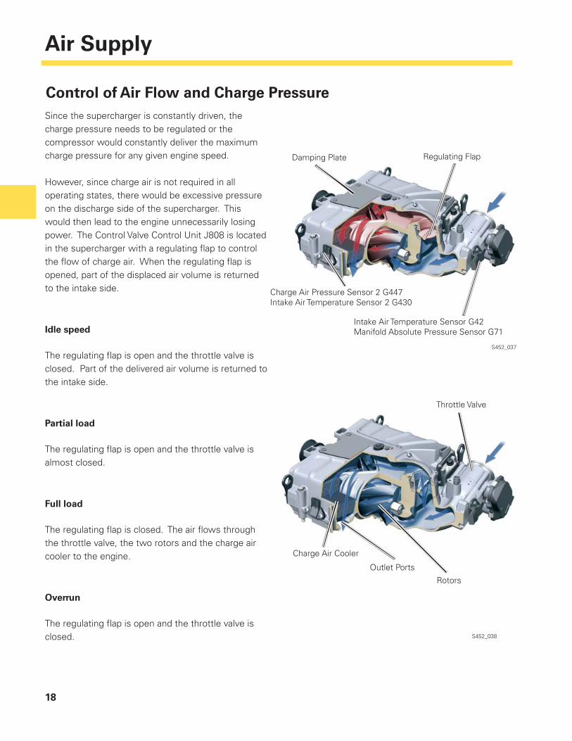
Since the supercharger is constantly driven, the charge pressure needs to be regulated or the compressor would constantly deliver the maximum charge pressure for any given engine speed.
However, since charge air is not required in all operating states, there would be excessive pressure on the discharge side of the supercharger. This would then lead to the engine unnecessarily losing power. The Control Valve Control Unit J808 is located in the supercharger with a regulating fl ap to control the fl ow of charge air. When the regulating fl ap is opened, part of the displaced air volume is returned to the intake side.
Idle speed
The regulating fl ap is open and the throttle valve is closed. Part of the delivered air volume is returned to the intake side.
Partial load
The regulating fl ap is open and the throttle valve is almost closed.
Full load
The regulating fl ap is closed. The air fl ows through the throttle valve, the two rotors and the charge air cooler to the engine.
Overrun
The regulating fl ap is open and the throttle valve is closed.
Control of Air Flow and Charge Pressure
Damping Plate Regulating Flap
Charge Air Pressure Sensor 2 G447Intake Air Temperature Sensor 2 G430
Intake Air Temperature Sensor G42Manifold Absolute Pressure Sensor G71
Charge Air Cooler
Rotors
Outlet Ports
Throttle Valve
19
Air Supply
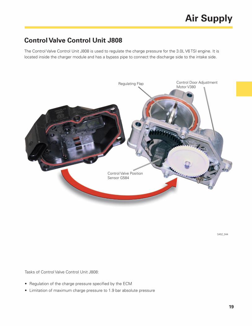
Control Valve Control Unit J808
The Control Valve Control Unit J808 is used to regulate the charge pressure for the 3.0L V6 TSI engine. It is located inside the charger module and has a bypass pipe to connect the discharge side to the intake side.
Tasks of Control Valve Control Unit J808:
• Regulation of the charge pressure specifi ed by the ECM
• Limitation of maximum charge pressure to 1.9 bar absolute pressure
Regulating Flap Control Door Adjustment Motor V380
Control Valve Position Sensor G584
S452_044
20
Air Supply
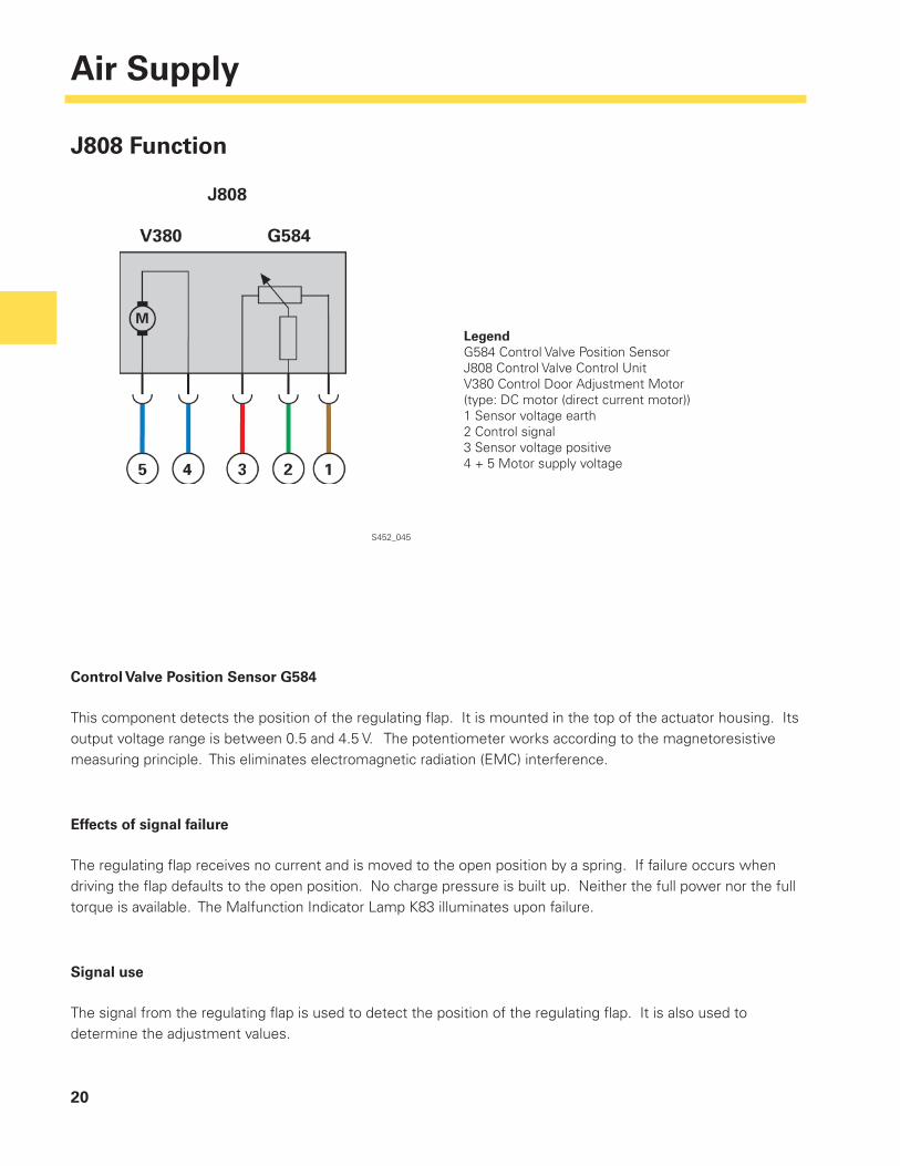
LegendG584 Control Valve Position SensorJ808 Control Valve Control UnitV380 Control Door Adjustment Motor(type: DC motor (direct current motor))1 Sensor voltage earth2 Control signal3 Sensor voltage positive4 + 5 Motor supply voltage
J808 Function
Control Valve Position Sensor G584
This component detects the position of the regulating fl ap. It is mounted in the top of the actuator housing. Its output voltage range is between 0.5 and 4.5 V. The potentiometer works according to the magnetoresistive measuring principle. This eliminates electromagnetic radiation (EMC) interference.
Effects of signal failure
The regulating fl ap receives no current and is moved to the open position by a spring. If failure occurs when driving the fl ap defaults to the open position. No charge pressure is built up. Neither the full power nor the full torque is available. The Malfunction Indicator Lamp K83 illuminates upon failure.
Signal use
The signal from the regulating fl ap is used to detect the position of the regulating fl ap. It is also used to determine the adjustment values.
S452_045
21
Air Supply
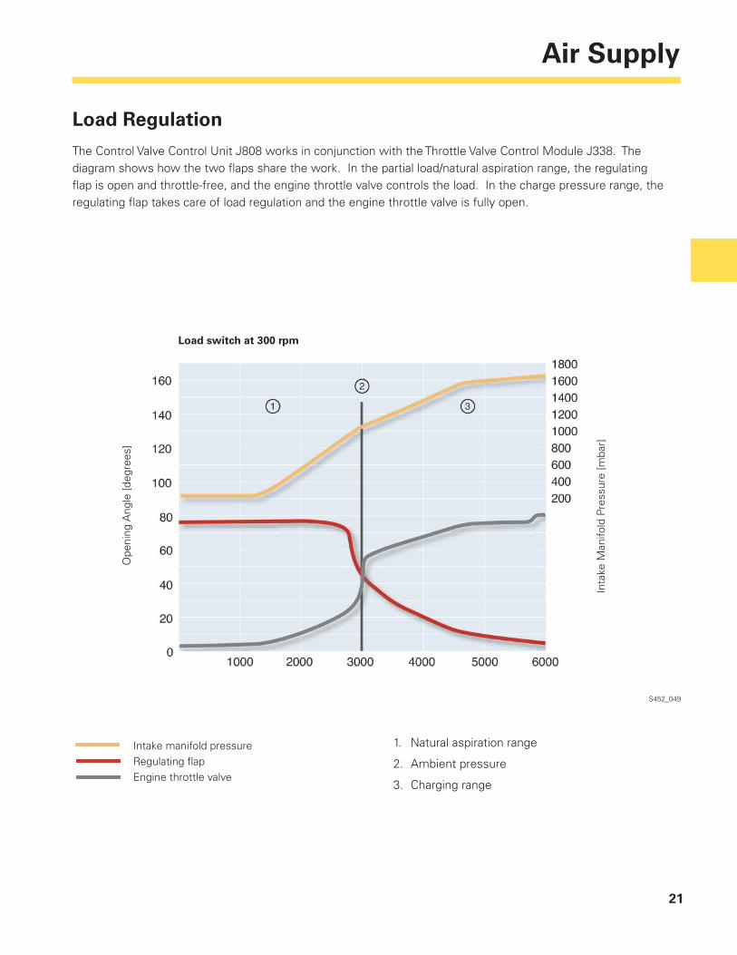
Load Regulation
The Control Valve Control Unit J808 works in conjunction with the Throttle Valve Control Module J338. The diagram shows how the two fl aps share the work. In the partial load/natural aspiration range, the regulating fl ap is open and throttle-free, and the engine throttle valve controls the load. In the charge pressure range, the regulating fl ap takes care of load regulation and the engine throttle valve is fully open.
S452_049
Load switch at 300 rpm
Ope
ning
Ang
le [d
egre
es]
Inta
ke M
anifo
ld P
ress
ure
[mba
r]
Intake manifold pressureRegulating fl apEngine throttle valve
1. Natural aspiration range
2. Ambient pressure
3. Charging range
22
Air Supply
S452_039
Particular care should be taken when removing and installing the charge air cooler.Please note the information in ElsaWeb.
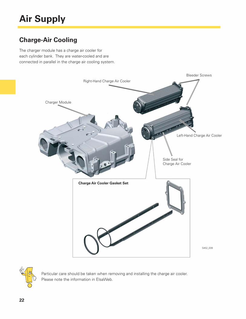
Charge-Air Cooling
The charger module has a charge air cooler for each cylinder bank. They are water-cooled and are connected in parallel in the charge air cooling system.
Charger Module
Right-Hand Charge Air Cooler
Bleeder Screws
Side Seal forCharge Air Cooler
Left-Hand Charge Air Cooler
Charge Air Cooler Gasket Set
23
Air Supply
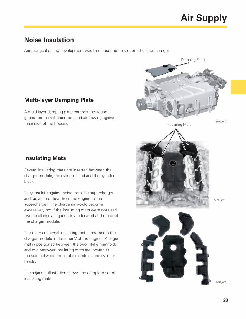
Noise Insulation
Another goal during development was to reduce the noise from the supercharger.
Multi-layer Damping Plate
A multi-layer damping plate controls the sound generated from the compressed air fl owing against the inside of the housing.
Insulating Mats
Several insulating mats are inserted between the charger module, the cylinder head and the cylinder block.
They insulate against noise from the supercharger and radiation of heat from the engine to the supercharger. The charge air would become excessively hot if the insulating mats were not used. Two small insulating inserts are located at the rear of the charger module.
There are additional insulating mats underneath the charger module in the inner V of the engine. A larger mat is positioned between the two intake manifolds and two narrower insulating mats are located at the side between the intake manifolds and cylinder heads.
The adjacent illustration shows the complete set of insulating mats
S452_040
S452_042
S452_043
Insulating Mats
Damping Plate
24
Air Supply
S452_046
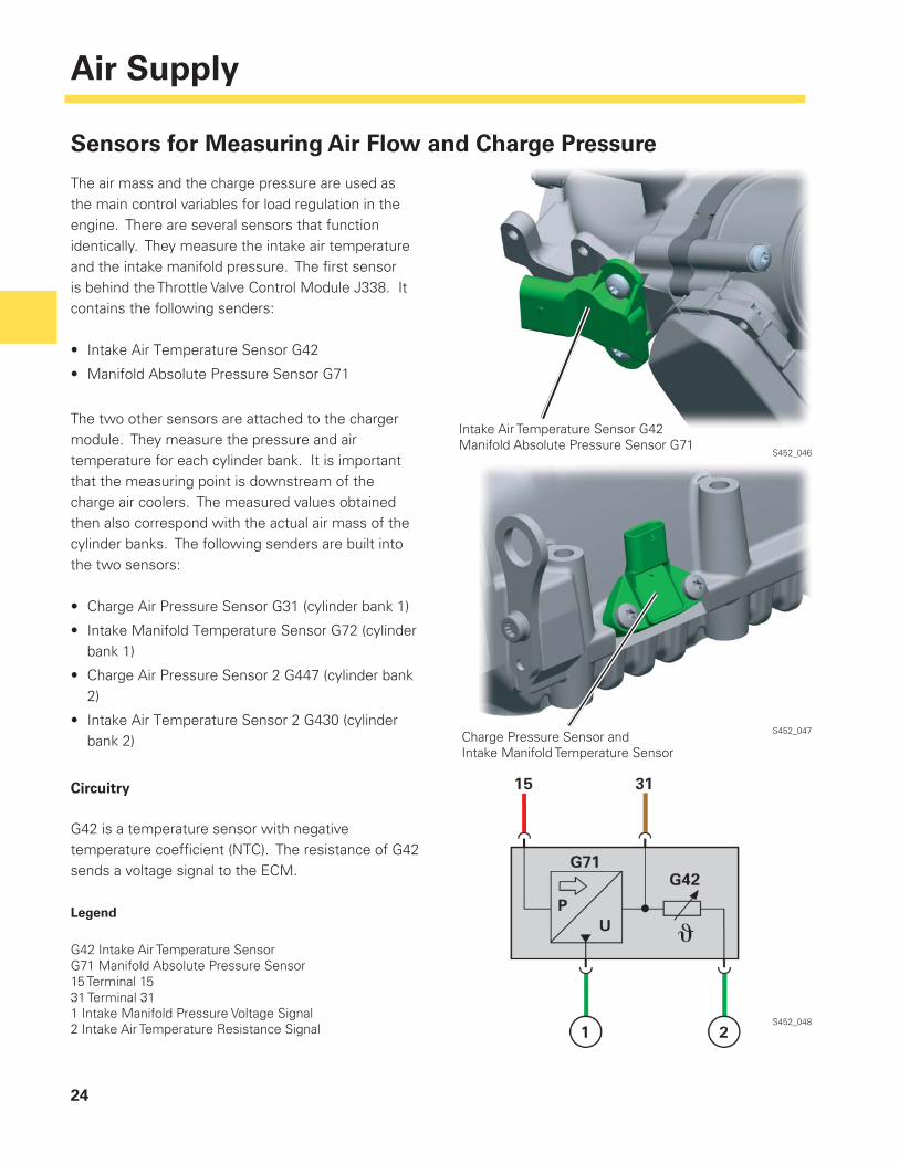
Sensors for Measuring Air Flow and Charge Pressure
The air mass and the charge pressure are used as the main control variables for load regulation in the engine. There are several sensors that function identically. They measure the intake air temperature and the intake manifold pressure. The fi rst sensor is behind the Throttle Valve Control Module J338. It contains the following senders:
• Intake Air Temperature Sensor G42
• Manifold Absolute Pressure Sensor G71
The two other sensors are attached to the charger module. They measure the pressure and air temperature for each cylinder bank. It is important that the measuring point is downstream of the charge air coolers. The measured values obtained then also correspond with the actual air mass of the cylinder banks. The following senders are built into the two sensors:
• Charge Air Pressure Sensor G31 (cylinder bank 1)
• Intake Manifold Temperature Sensor G72 (cylinder bank 1)
• Charge Air Pressure Sensor 2 G447 (cylinder bank 2)
• Intake Air Temperature Sensor 2 G430 (cylinder bank 2)
Circuitry
G42 is a temperature sensor with negative temperature coeffi cient (NTC). The resistance of G42 sends a voltage signal to the ECM.
Legend
G42 Intake Air Temperature SensorG71 Manifold Absolute Pressure Sensor15 Terminal 1531 Terminal 311 Intake Manifold Pressure Voltage Signal2 Intake Air Temperature Resistance Signal
S452_048
S452_047Charge Pressure Sensor andIntake Manifold Temperature Sensor
Intake Air Temperature Sensor G42Manifold Absolute Pressure Sensor G71
25
Air Supply
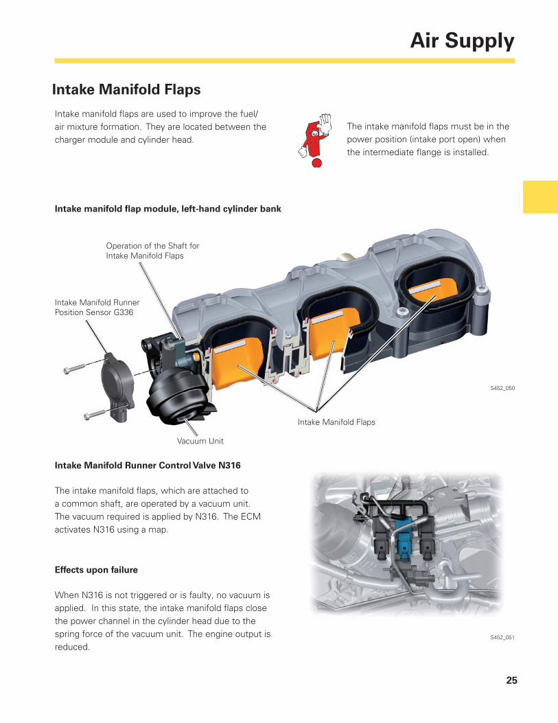
Intake Manifold Flaps
Intake manifold fl aps are used to improve the fuel/air mixture formation. They are located between the charger module and cylinder head.
The intake manifold fl aps must be in the power position (intake port open) when the intermediate fl ange is installed.
S452_050
Intake manifold fl ap module, left-hand cylinder bank
Operation of the Shaft forIntake Manifold Flaps
Intake Manifold Runner Position Sensor G336
Vacuum Unit
Intake Manifold Flaps
Intake Manifold Runner Control Valve N316
The intake manifold fl aps, which are attached to a common shaft, are operated by a vacuum unit. The vacuum required is applied by N316. The ECM activates N316 using a map.
Effects upon failure
When N316 is not triggered or is faulty, no vacuum is applied. In this state, the intake manifold fl aps close the power channel in the cylinder head due to the spring force of the vacuum unit. The engine output is reduced.
S452_051
26
Air Supply
S452_075
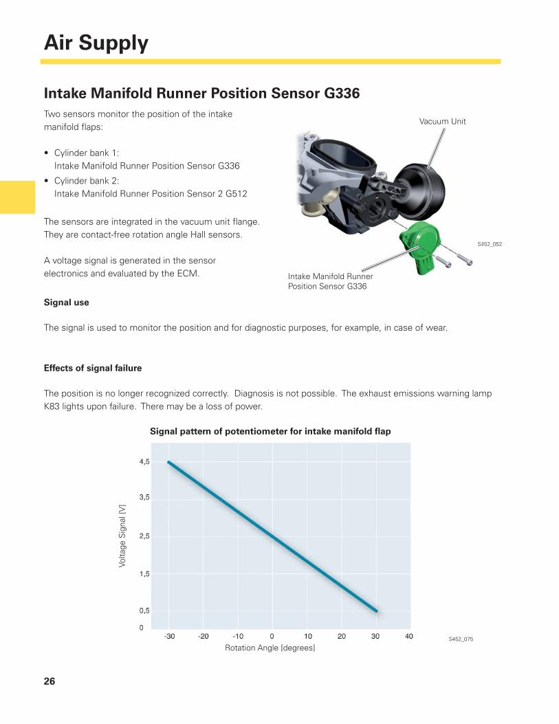
Two sensors monitor the position of the intake manifold fl aps:
• Cylinder bank 1: Intake Manifold Runner Position Sensor G336
• Cylinder bank 2: Intake Manifold Runner Position Sensor 2 G512
The sensors are integrated in the vacuum unit fl ange. They are contact-free rotation angle Hall sensors.
A voltage signal is generated in the sensor electronics and evaluated by the ECM.
Intake Manifold Runner Position Sensor G336
Signal use
The signal is used to monitor the position and for diagnostic purposes, for example, in case of wear.
Effects of signal failure
The position is no longer recognized correctly. Diagnosis is not possible. The exhaust emissions warning lamp K83 lights upon failure. There may be a loss of power.
Intake Manifold Runner Position Sensor G336
Vacuum Unit
S452_052
Signal pattern of potentiometer for intake manifold fl ap
Volta
ge S
igna
l [V
]
Rotation Angle [degrees]

Page intentionally left blank
28
Cooling System
S452_073
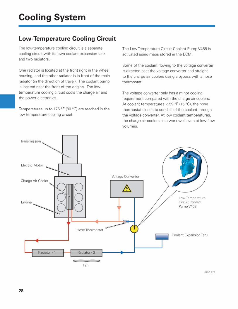
The low-temperature cooling circuit is a separate cooling circuit with its own coolant expansion tank and two radiators.
One radiator is located at the front right in the wheel housing, and the other radiator is in front of the main radiator (in the direction of travel). The coolant pump is located near the front of the engine. The low-temperature cooling circuit cools the charge air and the power electronics.
Temperatures up to 176 °F (80 °C) are reached in the low temperature cooling circuit.
The Low Temperature Circuit Coolant Pump V468 is activated using maps stored in the ECM.
Some of the coolant fl owing to the voltage converter is directed past the voltage converter and straight to the charge air coolers using a bypass with a hose thermostat.
The voltage converter only has a minor cooling requirement compared with the charge air coolers. At coolant temperatures < 59 °F (15 °C), the hose thermostat closes to send all of the coolant through the voltage converter. At low coolant temperatures, the charge air coolers also work well even at low fl ow volumes.
Transmission
Electric Motor
Charge Air Cooler
Engine
Radiator - 1 Radiator - 2
Fan
Hose ThermostatCoolant Expansion Tank
Low Temperature Circuit Coolant Pump V468
Voltage Converter
Low-Temperature Cooling Circuit
29
Cooling System
S452_026
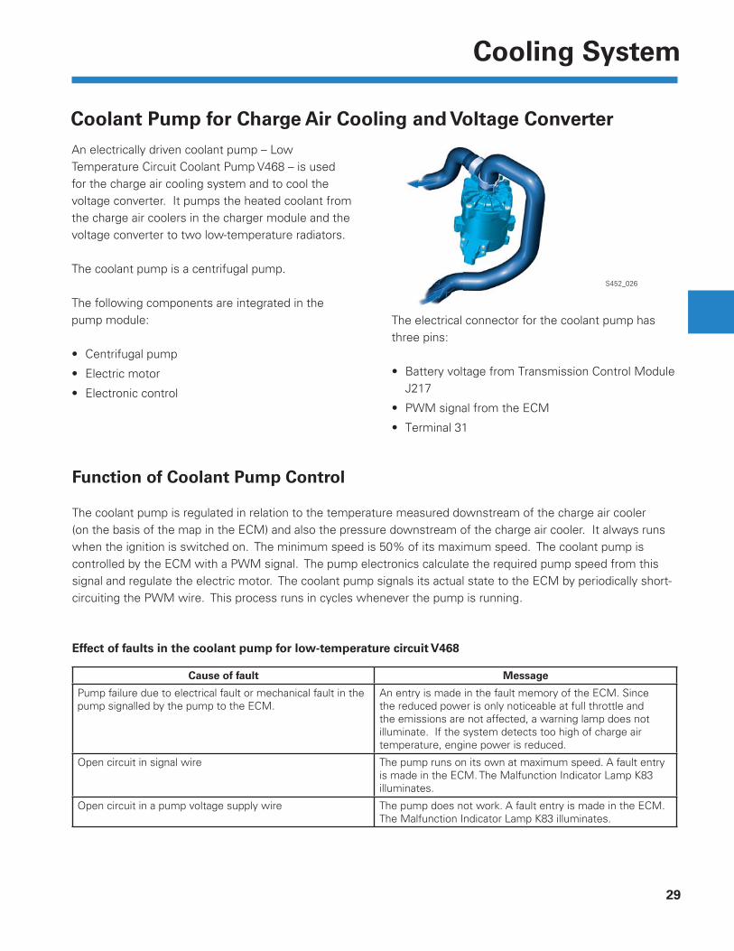
Coolant Pump for Charge Air Cooling and Voltage ConverterAn electrically driven coolant pump – Low Temperature Circuit Coolant Pump V468 – is used for the charge air cooling system and to cool the voltage converter. It pumps the heated coolant from the charge air coolers in the charger module and the voltage converter to two low-temperature radiators.
The coolant pump is a centrifugal pump.
The following components are integrated in the pump module:
• Centrifugal pump
• Electric motor
• Electronic control
The electrical connector for the coolant pump has three pins:
• Battery voltage from Transmission Control Module J217
• PWM signal from the ECM
• Terminal 31
Function of Coolant Pump Control
The coolant pump is regulated in relation to the temperature measured downstream of the charge air cooler (on the basis of the map in the ECM) and also the pressure downstream of the charge air cooler. It always runs when the ignition is switched on. The minimum speed is 50% of its maximum speed. The coolant pump is controlled by the ECM with a PWM signal. The pump electronics calculate the required pump speed from this signal and regulate the electric motor. The coolant pump signals its actual state to the ECM by periodically short-circuiting the PWM wire. This process runs in cycles whenever the pump is running.
Effect of faults in the coolant pump for low-temperature circuit V468
Cause of fault Message
Pump failure due to electrical fault or mechanical fault in the pump signalled by the pump to the ECM.
An entry is made in the fault memory of the ECM. Since the reduced power is only noticeable at full throttle and the emissions are not affected, a warning lamp does not illuminate. If the system detects too high of charge air temperature, engine power is reduced.
Open circuit in signal wire The pump runs on its own at maximum speed. A fault entry is made in the ECM. The Malfunction Indicator Lamp K83 illuminates.
Open circuit in a pump voltage supply wire The pump does not work. A fault entry is made in the ECM. The Malfunction Indicator Lamp K83 illuminates.
30
Cooling System
S452_067
High-Temperature Cooling CircuitAn innovative thermal management system is used on the 3.0L V6 engine. This increases the effi ciency of thermal distribution between the combustion engine, transmission, interior heating and electric motor.
The thermal management system allows the engine to heat up before allowing the coolant to circulate to the other components. This results in lower CO2 emissions, a corresponding reduction in fuel consumption and an increase in heating comfort.
The cooling system is regulated partly by temperature sensors and partly by ECM maps. The belt-driven coolant pump can be activated and deactivated using vacuum control.
The High Temperature Circuit Coolant Pump V467 ensures that the heat exchanger, ATF preheater and the e-machine have a suffi cient supply of coolant.
V467 delivers approximately 20 liters/min at maximum speed. It is tested in the same way as Low Temperature Circuit Coolant Pump V468.
Example diagram
Engine Coolant Temperature Sensor G62
Engine Temperature Control Temperature Sensor G694
Radiator
Coolant Pump
Thermostat
Engine Block
Cylinder Head
High Temperature Circuit Coolant Pump V467
Shut-Off Valve
Heating System Heat Exchanger
ATF Preheater
3/2-Way Valve
Electric Motor/Generator
31
Cooling System
On-Demand Coolant Pump
The coolant pump is belt driven and can be activated and deactivated as needed.
When deactivated, the coolant pump allows the engine to reach operating temperature as quickly as possible.
After a cold engine start, the coolant pump remains switched off for up to 2 minutes and then it is activated to protect the engine.
The delivery volume of the coolant pump is approximately 2 liters/min while the engine is idling.
S452_088
Coolant pump delivering Coolant pump not delivering
ShutterVacuum Connection
Coolant Pump
Please note the fi lling guidelines in ElsaWeb.
32
Exhaust Gas Treatment
Secondary Air System
The secondary air system ensures that the catalytic converters heat up quickly and that the exhaust gas emissions are reduced. The system blows air into the exhaust system downstream of the exhaust valves for a defi ned period after a cold start.
The unburned hydrocarbons and carbon monoxide contained in the exhaust gas or stored in the catalytic converter then react with oxygen in the combustion gases. The heat released allows the light-off temperature of the catalytic converter to be reached faster.
Combination Valve 2
Secondary Air Inlet Valves 1 + 2
Combination Valve 1
S452_053
Difference from previously used systems:
• Two secondary air inlet valves are used.
• The previous version had a single Secondary Air Injection Solenoid Valve N112.
Secondary Air Injection Motor
33
Exhaust Gas Treatment
S452_054
Checking the System
The secondary air mass is calculated by the ECM using the changing oxygen content. The diagnosis is not made during the normal secondary air operating time because the oxygen sensors reach their operating temperature too late. The system is controlled separately for diagnosis. The check is performed in several phases.
Measuring phase:
The secondary air pump and the secondary air inlet valves are activated by the ECM and the combination valves are opened. The ECM evaluates the signals from the oxygen sensors and compares them with the threshold values. If the threshold values are not reached, a fault is recorded.
Offset phase:
After switching off the secondary air pump, the quality of the mixture pre-control is evaluated. If the calculated value deviates too greatly, the result of the secondary air diagnosis is discarded. It is presumed that there is a fault in the mixture formation.
Secondary Air Inlet ValvesThe two secondary air inlet valves for controlling the two combination valves are located on the rear of the engine. They control the vacuum and are electrically activated by the ECM. If there is a fault in the system, the exhaust gas limit values may be exceeded very quickly.
Failure to assemble the connectors and hoses for the secondary air inlet valves correctly will result in diagnostic faults.
Combination Valves forSecondary Air
Secondary Air Injection Solenoid Valve N112
Secondary Air Injection Solenoid Valve 2 N320
34
Oil Supply
S452_021
Oil System
The lubrication system was designed to reduce the friction inside of the engine as well as the power consumption of the oil pump while retaining the ability to deliver oil as necessary.
As a result, a vane cell oil pump is being used in a gasoline engine for the fi rst time. This style of pump has been used previously in the 3.0L TDI diesel engine as a fuel supply pump or as a power steering pump.
Unfi ltered Oil Intake
Oil Filter
Oil Pressure Regulation Valve N428
Oil Pump
Oil Cooler
Coolant Connections
Unfi ltered oil channel
Filtered oil channel
35
Oil Supply
Volumetric Flow-Controlled Oil PumpLow delivery volume
Volumetric fl ow is used to reduce the power required to drive the oil pump. The pump is a vane cell oil pump with an adjustment ring that rotates on bearings. This rotation allows for variable oil delivery. Oil pressure can be applied to this adjustment ring at control surfaces 1 and 2 to move it against the force of the control springs.
At engine speeds up to 4,500 rpm or torque up to 221 lb/ft (300 Nm), the Oil Pressure Regulation Valve N428 is grounded by the ECM, opening the oil channel on the second control surface of the adjustment ring.
This allows oil pressure to act equally on both control surfaces.
The resulting forces are greater than those from the control springs and turn the adjustment ring counter-clockwise. The adjustment ring rotates into the center of the vane cell pump and reduces the size of the delivery chamber between the vane cells.
The lower pressure level (1.5+/–0.2 bar) is controlled in relation to the engine load, engine speed and oil temperature, which reduces the power required to drive the oil pump.
The Reduced Oil Pressure Switch F378 is located in the “V” of the engine and measures the low pressure level. Its measuring range is between 0.75 - 1.05 bar (relative pressure). If there is a system fault, the red oil warning lamp in the instrument panel will illuminate.
S452_081
S452_082
Oil Pressure Regulation Valve N428Activated
Crankshaft Oil Channel
Low delivery volume
Oil Pressure Appliedfrom Crankshaft OilChannel
DeliveryChamber
Vane Cells
Control Surface 2
Control Spring
Control Surface 1Adjustment Ring
Counter Bearing
36
Oil Supply
From a speed of 4,500 rpm or a torque of 221 lb/ft (300 Nm), the ground to the Oil Pressure Regulation Valve N428 is opened by the ECM, closing the oil delivery to control surface 2.
The oil pressure (3.6+/–0.4 bar) applied now only acts on control surface 1 and applies a lower force against the force of the control spring.
Large delivery volumeThe control spring rotates the adjustment ring clockwise around the counter bearing. The adjustment ring is now rotated away from the center position and enlarges the delivery chamber between the individual vane cells.
More oil is delivered due to the larger chambers between the vane cells.
If the N428 fails, the pump will only run at a high pressure level.
S452_083
S452_084
S452_085
The Oil Pressure Switch F22 is located on the oil fi lter module and measures the high-pressure level. Its measuring range is between 2.4 - 3.1 bar (relative pressure). If there is a system fault, the yellow oil warning lamp in the instrument panel will illuminate.
Solenoid Valve Closed When Not Energized
Oil pressures at 212 °F (100 °C) oil temperature
Oil
pres
sure
(bar
)
Engine speed (rpm)
Solenoid valve not energizedSolenoid valve activated
Large delivery volume
DeliveryChamber
Control Surface 2
Control Surface 2Adjustment Ring Set toMaximum Delivery
Counter Bearing
37
Oil Supply
Oil Level Sensor
Oil Level Thermal Sensor G266 Using the hot-wire principle
This is the design of the previous oil level sensor and works using a heated wire. The measuring element is briefl y heated to a temperature above the current oil temperature.
After the heating voltage is switched off, the measuring element cools to the temperature level of the oil. The oil level is calculated from the time required for cooling.
Oil Level Thermal Sensor G266 Using ultrasonic technology
This is the new oil level sensor design and operates using ultrasonic impulses emitted from the base that are refl ected by the surface of the oil. The oil level is calculated from the time difference between the transmitted and returned pulse on the basis of the speed of sound.
Both sensors process their measured signals in an electronic system that is integrated in the sensor housing. A PWM signal is the output. (PWM = pulse width modulation).
Advantages of the ultrasound sensor:
• The sensor signal is available very quickly (after approximately 100 ms)
• Low power consumption < 0.5 A (oil temperature and oil level sender up to 5 A)
S452_080
S452_086
38
Oil Supply
Display of Oil Level on Infotainment System
A traditional oil dipstick has been eliminated and the oil can now be checked using the infotainment system. The car menu in the RNS850 display is used to check the oil level. Any warnings regarding the oil level are displayed in the instrument cluster.
Dynamic measurement
• Engine speed
• Longitudinal and lateral acceleration from the ESC control module
• Hood switch (hood must be closed)
• Engine temperature (engine should be at operating temperature)
• Driving cycle after last hood contact > 31 miles (50 km) and
• There must be a certain number of measured values within the driving cycle.
The dynamic measurement is made while the vehicle is driving.
The measurement is interrupted if:
• there are high acceleration values,
• oil temperature > 284 ° F (140 °C) or
• hood switch F266 has been operated.
Two measuring methods are used to check the oil level – dynamic and static measurement.
Important factors for each measurement are:
Static measurement
• Ignition “On” (the measuring process is started as soon as the driver’s door is opened to obtain a measuring result as quickly as possible)
• Engine oil temperature > 104 °F (40°C)
• Engine speed < 100 rpm
• Engine is stationary > 60 sec.
The acceleration values from the ESC control module are used to check if the vehicle is on an incline.
The parking brake signal is used to ensure that the vehicle is stationary.
39
Oil Supply
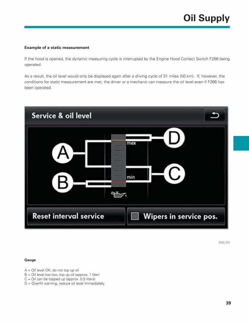
Example of a static measurement
If the hood is opened, the dynamic measuring cycle is interrupted by the Engine Hood Contact Switch F266 being operated.
As a result, the oil level would only be displayed again after a driving cycle of 31 miles (50 km). If, however, the conditions for static measurement are met, the driver or a mechanic can measure the oil level even if F266 has been operated.
S452_072
Gauge
A = Oil level OK, do not top up oilB = Oil level too low, top up oil (approx. 1 liter)C = Oil can be topped up (approx. 0.5 liters)D = Overfi ll warning, reduce oil level immediately
40
Oil Supply
Oil Level Measurement
• The vehicle must be on level ground.
• The oil temperature must be between 140 and 248 °F (60 and 120 °C).
• Wait briefl y after stopping the engine to allow the oil to fl ow back into the oil sump.
• Turn the ignition on, press the “CAR” infotainment button and then the “Service” function button.
Possible cause Remedy
Lights up
Lights up
Flashes
Flashes
Engine oil level too low
Problem with the engine oil pressure
Engine oil pressure too low
Engine oil system malfunction
Turn off engine. Check oil level.
Drive to a dealership below the maximum engine speed indicated in the instrument cluster and have the system checked.STOP! Do not continue driving! Turn off engine. Check oil level. Do not continue driving if the warning lamp fl ashes, even if the oil level is OK. Seek professional help.
Visit a dealership. Have the engine oil sensor checked.
The display of the oil pressure/oil level in the dash panel insert is displayed as follows:
The oil tester dipstick T40178 can be used to check the oil level during service.

Page intentionally left blank
42
Fuel System
S452_055
High pressure
Low pressure
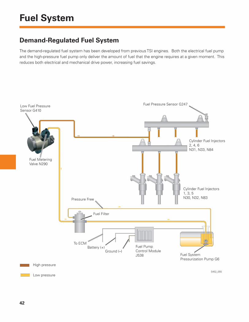
Demand-Regulated Fuel System
The demand-regulated fuel system has been developed from previous TSI engines. Both the electrical fuel pump and the high-pressure fuel pump only deliver the amount of fuel that the engine requires at a given moment. This reduces both electrical and mechanical drive power, increasing fuel savings.
Low Fuel Pressure Sensor G410
Fuel MeteringValve N290
Pressure Free
Fuel Filter
To ECMBattery (+)
Ground (–)Fuel PumpControl Module J538 Fuel System
Pressurization Pump G6
Cylinder Fuel Injectors1, 3, 5N30, N32, N83
Cylinder Fuel Injectors2, 4, 6N31, N33, N84
Fuel Pressure Sensor G247
43
Fuel System
S452_057
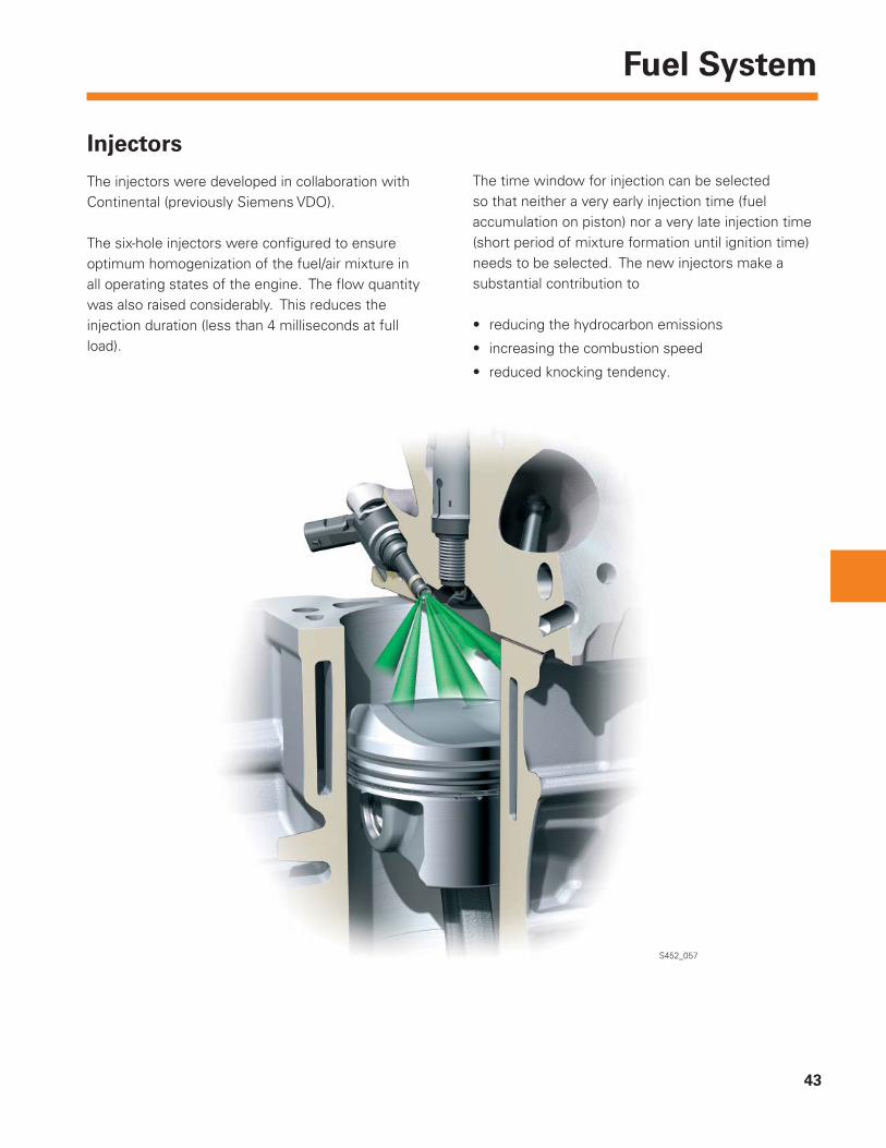
Injectors
The injectors were developed in collaboration with Continental (previously Siemens VDO).
The six-hole injectors were confi gured to ensure optimum homogenization of the fuel/air mixture in all operating states of the engine. The fl ow quantity was also raised considerably. This reduces the injection duration (less than 4 milliseconds at full load).
The time window for injection can be selected so that neither a very early injection time (fuel accumulation on piston) nor a very late injection time (short period of mixture formation until ignition time) needs to be selected. The new injectors make a substantial contribution to
• reducing the hydrocarbon emissions
• increasing the combustion speed
• reduced knocking tendency.
44
Fuel System
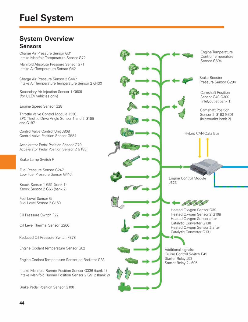
System Overview
Charge Air Pressure Sensor G31Intake Manifold Temperature Sensor G72
Manifold Absolute Pressure Sensor G71Intake Air Temperature Sensor G42
Charge Air Pressure Sensor 2 G447Intake Air Temperature Temperature Sensor 2 G430
Secondary Air Injection Sensor 1 G609(for ULEV vehicles only)
Engine Speed Sensor G28
Throttle Valve Control Module J338EPC Throttle Drive Angle Sensor 1 and 2 G188 and G187
Control Valve Control Unit J808Control Valve Position Sensor G584
Accelerator Pedal Position Sensor G79Accelerator Pedal Position Sensor 2 G185
Brake Lamp Switch F
Fuel Pressure Sensor G247Low Fuel Pressure Sensor G410
Knock Sensor 1 G61 (bank 1)Knock Sensor 2 G66 (bank 2)
Fuel Level Sensor GFuel Level Sensor 2 G169
Oil Pressure Switch F22
Oil Level Thermal Sensor G266
Reduced Oil Pressure Switch F378
Engine Coolant Temperature Sensor G62
Engine Coolant Temperature Sensor on Radiator G83
Intake Manifold Runner Position Sensor G336 (bank 1)Intake Manifold Runner Position Sensor 2 G512 (bank 2)
Brake Pedal Position Sensor G100
Additional signals:Cruise Control Switch E45Starter Relay J53Starter Relay 2 J695
Heated Oxygen Sensor G39 Heated Oxygen Sensor 2 G108 Heated Oxygen Sensor afterCatalytic Converter G130Heated Oxygen Sensor 2 afterCatalytic Converter G131
Engine Control Module J623
Engine Temperature Control Temperature Sensor G694
Brake Booster Pressure Sensor G294
Camshaft Position Sensor G40 G300 (inlet/outlet bank 1)
Camshaft Position Sensor 2 G163 G301(inlet/outlet bank 2)
Hybrid CAN-Data Bus
Sensors
45
Fuel System
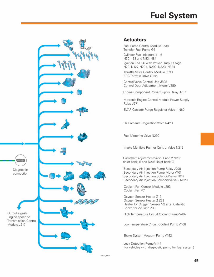
Actuators
Oxygen Sensor Heater Z19Oxygen Sensor Heater 2 Z28Heater for Oxygen Sensor 1-2 after Catalytic Converter Z29 and Z30
High Temperature Circuit Coolant Pump V467
Low Temperature Circuit Coolant Pump V468
Brake System Vacuum Pump V192
Leak Detection Pump V144(for vehicles with diagnostic pump for fuel system)
Secondary Air Injection Pump Relay J299Secondary Air Injection Pump Motor V101Secondary Air Injection Solenoid Valve N112Secondary Air Injection Solenoid Valve 2 N320
Coolant Fan Control Module J293Coolant Fan V7
Fuel Pump Control Module J538Transfer Fuel Pump G6
Cylinder Fuel Injectors 1 – 6N30 – 33 and N83, N84
Throttle Valve Control Module J338EPC Throttle Drive G186
Ignition Coil 1-6 with Power Output Stage N70, N127, N291, N292, N323, N324
Control Valve Control Unit J808Control Door Adjustment Motor V380
Engine Component Power Supply Relay J757
Motronic Engine Control Module Power Supply Relay J271
EVAP Canister Purge Regulator Valve 1 N80
Oil Pressure Regulation Valve N428
Fuel Metering Valve N290
Intake Manifold Runner Control Valve N316
Camshaft Adjustment Valve 1 and 2 N205(inlet bank 1) and N208 (inlet bank 2)
Output signals:Engine speed toTransmission Control Module J217
Diagnosticconnection
S452_060
46
Engine Management
Engine Control Module
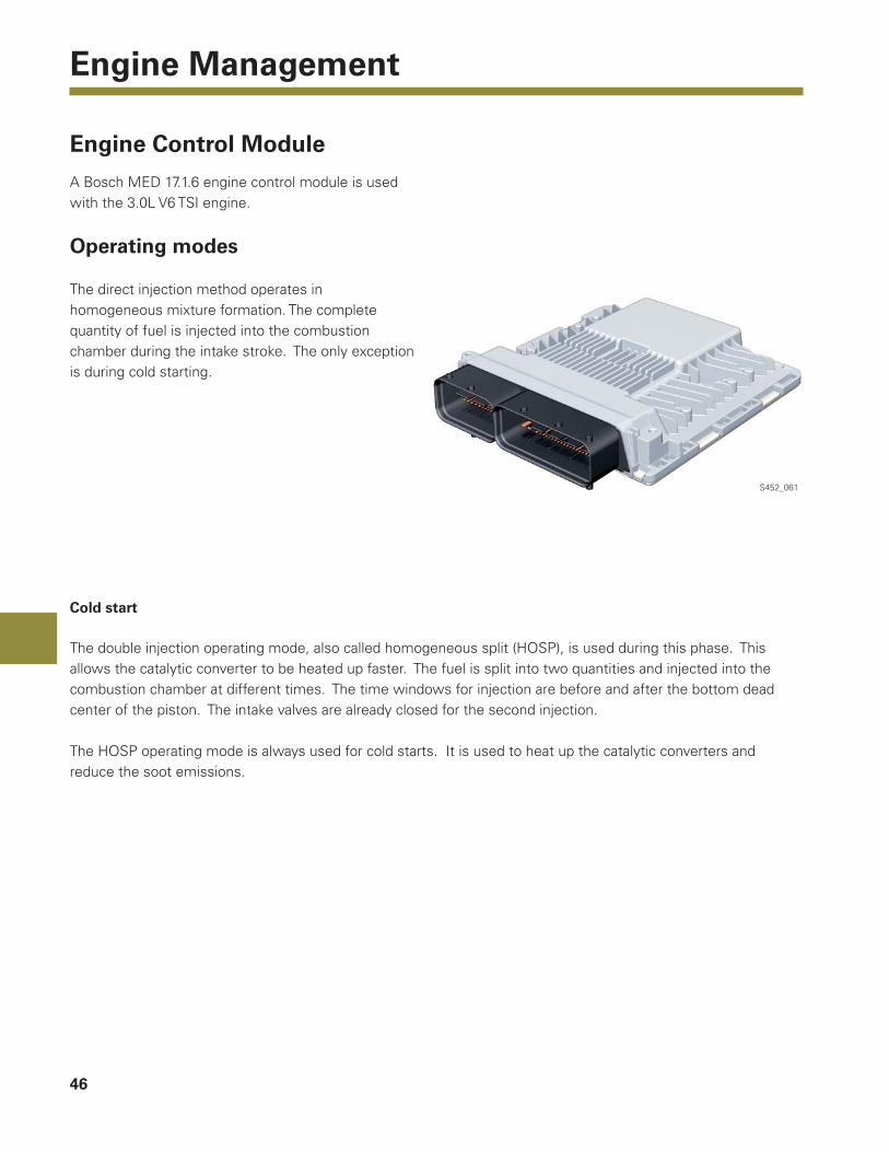
A Bosch MED 17.1.6 engine control module is used with the 3.0L V6 TSI engine.
Operating modes
The direct injection method operates in homogeneous mixture formation. The complete quantity of fuel is injected into the combustion chamber during the intake stroke. The only exception is during cold starting.
Cold start
The double injection operating mode, also called homogeneous split (HOSP), is used during this phase. This allows the catalytic converter to be heated up faster. The fuel is split into two quantities and injected into the combustion chamber at different times. The time windows for injection are before and after the bottom dead center of the piston. The intake valves are already closed for the second injection.
The HOSP operating mode is always used for cold starts. It is used to heat up the catalytic converters and reduce the soot emissions.
S452_061
47
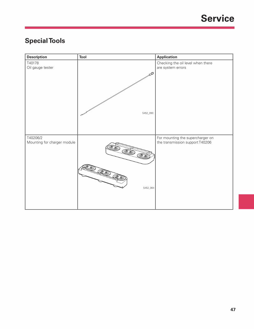
Service
Description Tool Application
T40178Oil gauge tester
Checking the oil level when thereare system errors
T40206/2Mounting for charger module
For mounting the supercharger onthe transmission support T40206
S452_090
S452_064
Special Tools
48
Glossary
Blow-by gases
These are gases that escape past the pistons from the combustion chamber and into the crankcase while the engine is running. This is caused by both the high pressures in the combustion chamber and normal leaks past the piston rings.
The blow-by gases are extracted from the crankcase through a crankcase ventilation system and returned to the combustion process.
Hall sender
Also known as Hall sensor or Hall generator, this component uses the Hall effect to measure magnetic fi elds and currents or for position sensing. If a current fl ows through a Hall sender and it is moved into a vertical magnetic fi eld, it supplies an output voltage that is proportional to the magnetic fi eld strength and current.
Cracked connecting rod
This term for connecting rods refers to their manufacturing process. The connecting rod shank and connecting rod cap are separated from each other by deliberate fracturing (cracking). The advantage of this method is that the two pieces fi t together precisely.
Light-off temperature
The temperature at which the conversion rate of the catalytic converter amounts to 50%. This is very important for future emissions standards, as they require correspondingly low pollutant emissions even when the engine is cold.
EMC
This abbreviation stands for electromagnetic compatibility. It ensures that technical devices do not interfere with each other due to unwanted electrical or electromagnetic effects.
PWM signal
The abbreviation PWM stands for pulse width modulated signal. This is a digital signal that switches a variable (for example, an electric current) between two values.
The intervals of these changes are varied depending on the control. Digital signals can be transferred by this method.
ESC
This abbreviation stands for Electronic Stability Control. It was previously known as ESP (Electronic Stability Program).

Page intentionally left blank

50
Knowledge Assessment
An on-line Knowledge Assessment (exam) is available for this Self-Study Program.
The Knowledge Assessment may or may not be required for Certifi cation.
You can fi nd this Knowledge Assessment at:
www.vwwebsource.com
For Assistance, please call:
Volkswagen Academy
Certifi cation Program Headquarters
1-877-791-4838
(8:00 a.m. to 8:00 p.m. EST)
Or, E-mail:

51
Notes
Volkswagen Group of America2200 Ferdinand Porsche DriveHerndon, VA 20171October 2010