Embed Size (px)
Citation preview

SELECTION OF PNEUMATIC CYLINDERS
• Single or Double acting• Dimensional standards like ISO, VDMA, CETOP, AFNOR.• Constructional details like – Piston rod, tie rod, square tube, Mickey
mouse tube, rodless etc.• Force to be exerted (Bore dia)• Distance to be moved (stroke)• Surrounding medium (special material of construction / type of seals)• Air pressure available.• Cushioned / Non cushioned.• Ambient temperature for selection of seal material.• Speed of actuation• Position detection (Reed switch type)• Mountings• Stop tube length for long stroke cylinders.

SPECIFICATION OF PNEUMATIC CYLINDERS
• Cylinder thrust.• Air consumption.• Piston velocity.• Type of mounting.• Couplings
Following points need to be considered while selecting a pneumatic cylinder.
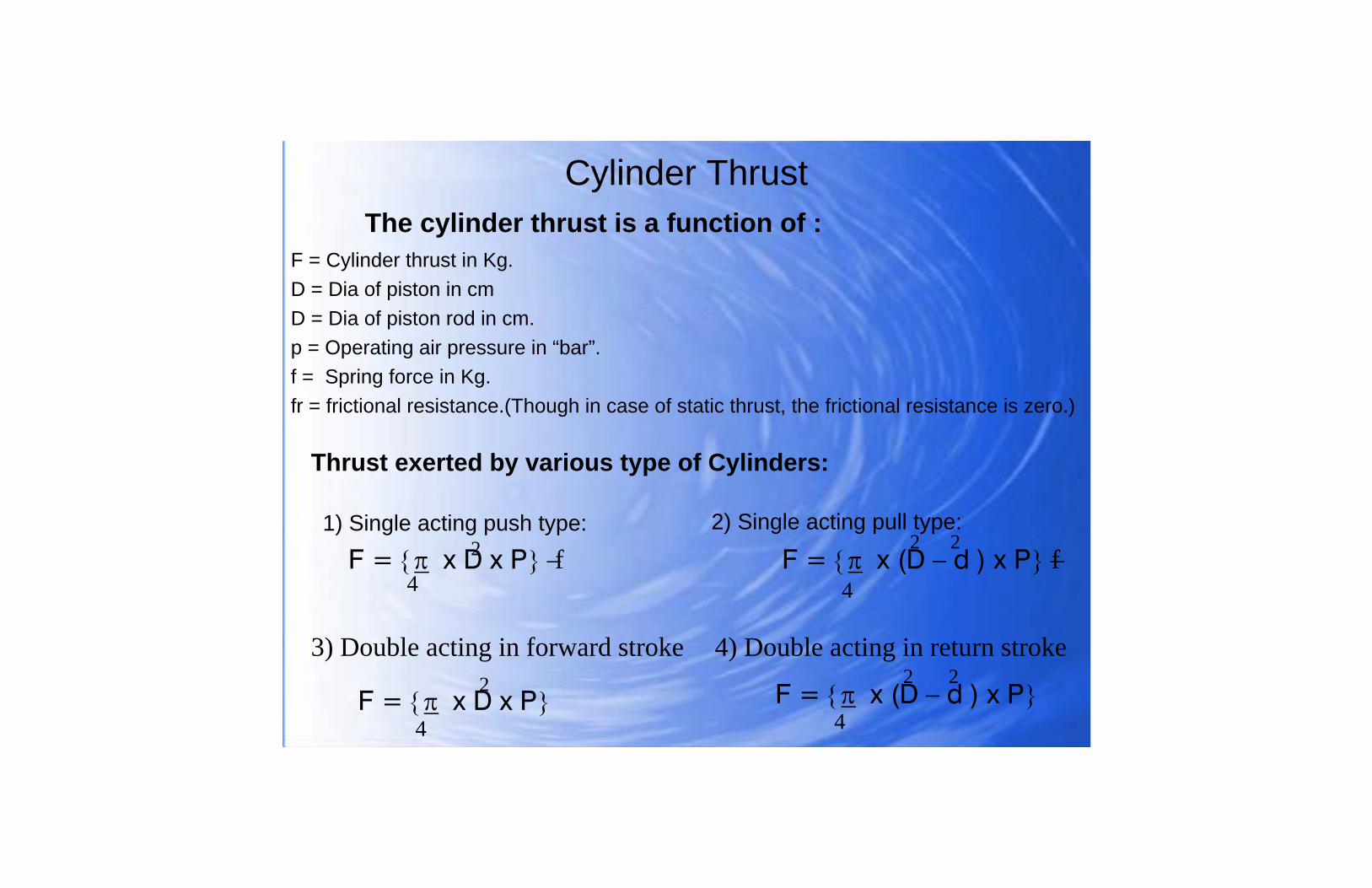
Cylinder ThrustThe cylinder thrust is a function of :
F = Cylinder thrust in Kg.D = Dia of piston in cmD = Dia of piston rod in cm.p = Operating air pressure in “bar”.f = Spring force in Kg.fr = frictional resistance.(Though in case of static thrust, the frictional resistance is zero.)
Thrust exerted by various type of Cylinders:
1) Single acting push type:
F = {π x D x P} − F = {π x (D – d ) x P} −4
f2 22f
4
2) Single acting pull type:
3) Double acting in forward stroke 4) Double acting in return stroke
F = {π x D x P} 4
2 F = {π x (D – d ) x P} 22
4

Examples 1
To calculate the thrust generated by an 80mm (8cm) push type single acting cylinder ( forward stroke ) at working pressure of 5 bar and with return spring of 50 kgs force.
F = {π x D x P}− f4
= {3.14 x 8 x 5}− 50
= 251.2 - 50
= 201.2 Kgs.
2
24

Examples 2
To calculate the thrust generated by an 80mm (8cm) pull type single acting cylinder ( forward stroke ) at working pressure of 5 bar and with return spring of 50 kgs force. (with piston rod dia of 25mm or 2.5cm.)
F = {π x (D-d ) x P}−f4
= {3.14 x (8-2.5 ) x 5}− 50
= 226.7 - 50
= 176.7 Kgs.
2
2
4
2
2

Examples 3
To calculate the thrust generated by an 80mm (8cm) double acting cylinder at working pressure of 5 bar. (with piston rod dia of 25mm or 2.5cm.) in return stroke
F = {π x (D-d ) x P}4
= {3.14 x (8-2.5 ) x 5}
= 226.7
2
2
4
2
2

Examples 4
To calculate the thrust generated by an 80mm (8cm) double acting cylinder ( forward stroke ) at working pressure of 5 bar.
F = {π x D x P}4
= {3.14 x 8 x 5}
= 251.2
2
2
4

AIR CONSUMPTIONThe air consumption data for a cylinder is required to estimate the compressor capacity. The calculations include air consumption during forward as well as return stroke.
The free air consumption for forward stroke is calculated as follows:
Free air consumption = piston area x (operating pressure + 1.013) x stroke
The free air consumption for return stroke is also calculated similarly and added to arrive at total free air consumption of cylinder during one complete cycle.

Theoretical air consumption calculations:
LetD = Dia of piston in cm.d = piston rod dia.L = stroke in cm.P = Air pressure in bar
C = {π x D x (P+1) x L} / 1000
Free air consumption in litres for forward stroke
Free air consumption in litres for return stroke
C = {π x (D – d ) x (P+1) x L} / 10004
4
22
2

Piston Velocity
Factors governing the piston velocity are: the operating pressure, opposing forces, inside diameter and length of the air line between the control valve and cylinder and the size of the control valve. The piston velocity may be increased or decreased with the help of a quick exhaust valve or flow control valve respectively. The average piston speed at no – load is between 100 – 500mm/ sec. Depending on the frequency of operation and the speed required, proper type and size of valve needs to be selected.

Example:
To calculate the air consumption in litres for 80mm dia bore cylinder with 300mm stroke having a piston rod dia of 25mm and working at 5 bar air pressure
Free air consumption for forward stroke:
C = {π x D x (P+1) x L} / 1000
C = {3.14 x 8 x 6 x 30} / 1000
C = 9.043 ltrs.
Free air consumption for return stroke:
C = {π x (D – d ) x (P+1) x L} / 1000
C = {3.14 x (8 – 2.5 ) x 6 x 30} / 1000
C = 8.16 ltrs.
4
4
2
2
4
2
4
2
Contd….

Hence for one complete cycle of operation for this cylinder, the free air consumption will be (9.043 + 8.16 = 17.203) litres
Number of strokes per minute required from this cylinder to perform certain work will give us free compressed air consumption per minute for this cylinder.
Free air consumption =
Free air consumption per cycle x strokes per minute

Mounting types• Front plate mounting.• Rear plate mounting.• Double trunion mounting.• Centre trunion mounting.• Neck mounting.• Leg mounting.• Hinge mounting.
Couplings
• Fork
• Rod eye end.
• Universal coupling

Graph A
Piston speed with ¼” spool / exel valve
Graph B
Piston speed with ¼” high flow valve
Graph C
Piston speed with 3/8” poppet valve
Graph D
Piston speed with ¾” Poppet valve.
Cylinder valve performance predictor graph
Piston speed (inch / sec)
Note: The chart shows piston speed at no load

Examples:
1) To determine the piston speed of 4” cylinder working at ½ load capacity, when operated from ¼” spool valve
On graph A, the piston speed corresponding to 4” cylinder is 9”/sec. Hence for half cylinder loading, the piston speed will be = 9 x 0.671
= 6.04 inch/sec
2) To determine the piston speed of 4” cylinder working at ½ load capacity, when operated from 3/8” poppet valve.
On graph C, the piston speed corresponding to 4” cylinder is 15”/sec. Hence for half cylinder loading, the piston speed will be = 15 x 0.671
= 10.06 inch/sec

Selection of valves
The following parameters need to be considered for selection:
• Internal construction and other features
• Valve capacity

Internal construction and other features of valves
• Flow requirement depending on size of actuator & speed of movement.• Response time of the valve.• Air pressure available.• Type of actuation required – solenoid, air pilot or mechanical• Type of connection – sub base, side ported.• No. of positions – two or three position.• Return mechanism such as spring, air pilot.• Lubricated or non lubricated.• Functions like 2/2, 3/2, 5/2, 5/3, normally open or close etc.

Internal construction details of valves
Direct acting
2/2 Valves
• Plunger opens/ closes the valve either directly or thro’ attached diaphragm• Quick response to actuation.• Operates at zero pressure as well in vacuum
Diaphragm operated• Differential pressure on diaphragm operates the valve.• Quick response to actuation.• Longer life since there are no sliding members
Piston operated
• Differential pressure on piston to operate the valve
• Robust in construction
• Ideal for heavy duty application.

Internal construction details of valves 5/2 directional control valves
Spool design• Valve operation thro’ longitudinal spool movement.
• Compact in construction with med. Flow capacities.
• Possibility of different flow path configurations.
• Control of flow thro’ face sealing by disc or plug.
• High flow capacities and faster response.
• Self cleaning property makes it ideal under adverse conditions.
• Manually operated rotary disc interconnect ports.
• Compact design, ideal for 5/3 operations.
• Movement of slide control air flow.
• Compact design with long life expectancy
Poppet Design
Rotary Disc design
Plane slide design

Flow Measurement
The selection of valve for any automation, needs to be evaluated in terms of its flow rate to determine its capability to meet the final application.
Flow rate is defined as the volume of air passing thro’ a given cross section in a unit time.
Typical unit for measuring flow rate is Nl/m (i.e.. Nominal litres per minute) or SCFM (standard cubic feet per minute) expressed at standard conditions of pressure and temperature.

Flow coefficient (Cv)
Cv is a measure of flow capacity. It is measured as the flow of water thro’ the cross section of the valve in US gallons (3.785 litres) per minute when the pressure differential is 1 psi.
Flow rate in litres/sec thro’ a valve can be calculated to a limited accuracy by the formula:
Air flow rate (litres/sec) = 6.694 Cv(outlet pressure + 1.013) x P

Pneumatic valve selection
To select a valve, following details need to be taken onto account:
• Cylinder bore (D cm)• Stroke of cylinder (L cm)• Required stroke time ( T sec)• Pneumatic pressure available ( P)
Referring to tables shown in next slide, constant “M” compression factor can be substituted in the formula below:
Cv = Cyl. Area x stroke x M x compression factor475 x stroke time in sec.

Table
0.03611.2100.03810.390.0399.280.0428.070.0457.160.0496.050.0545.140.0624.030.0723.020.0922.01
“M” constant
Compression factor
Inlet Pressure

Example
• Cylinder bore = 63 mm
• Stroke = 300 mm
• Required time = 1 sec
• Inlet pressure = 7 bar
From table, compression factor = 8.0
“M” = 0.042
Area = 31.17
Cv = 31.17 x 30 x 0.042 x 8.0475 x 1
Cv = 0.66
G1/4 – 5/2 Exel valve has a Cv of 0.7 and hence appropriate for the purpose

Effect of weight of fork on cylinder components
Fork as per Customer design
Schrader Std. Fork

Effect of weight of fork on cylinder components (angular mounting)
Schrader Std. Fork
Fork as per Customer design


Comparison of Schrader standard fork attachment & Customer design fork attachment
• Smaller / standard fork can give same functionality with considerably ( one third load) less cantilever load on piston rod bearings and piston seal. This will help in getting longer life of piston seals.
• Higher fork weight for non standard fork results in additional wear and tear of bearing wear ring and piston seals.
• Being non standard, it can not be tooled up for smaller quantities.
• Higher lead time and cost.