Embed Size (px)
Citation preview
Data sheet
Valve Station in stainless steel ICF SS 20 and ICF SS 25
DKRCI.PD.FT0.B5.02 | 520H10451 | 1© Danfoss | DCS (mwa) | 2017.09
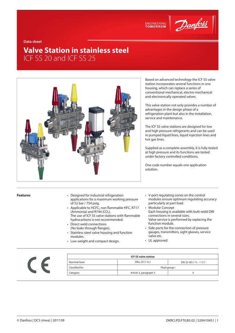
Based on advanced technology the ICF SS valve station incorporates several functions in one housing, which can replace a series of conventional mechanical, electro-mechanical and electronically operated valves.
This valve station not only provides a number of advantages in the design phase of a refrigeration plant but also in the installation, service and maintenance.
The ICF SS valve stations are designed for low and high pressure refrigerants and can be used in pumped liquid lines, liquid injection lines and hot gas lines.
Supplied as a complete assembly, it is fully tested at high pressure and its functions are tested under factory controlled conditions.
One code number equals one application solution.
Features • Designed for industrial refrigeration applications for a maximum working pressure of 52 bar / 754 psig.
• Applicable to HCFC, non flammable HFC, R717 (Ammonia) and R744 (CO2). The use of ICF SS valve stations with flammable hydrocarbons is not recommended.
• Direct weld connections (No leaks through flanges).
• Stainless steel valve housing and function modules.
• Low weight and compact design.
• V-port regulating cones on the control modules ensure optimum regulating accuracy particularly at part load.
• Modular Concept Each housing is available with butt-weld DIN connections in several sizes. Valve service is performed by replacing the function module.
• Side ports for the connection of pressure gauges, transmitters, sight glasses, service valve etc.
• UL approved
ICF SS valve station
Nominal bore DN≤ 25 (1 in.) DN 32-40 (1 ¼ - 1 ½”)
Classified for Fluid group I
Category Article 3, paragraph 3 II
Data sheet | Valve Station in stainless steel, types ICF SS 20 and ICF SS 25
DKRCI.PD.FT0.B5.02 | 520H10451 | 2© Danfoss | DCS (mwa) | 2017.09
Contents Page
Features . . . . . . . . . . . . . . . . . . . . . . . . . . . . . . . . . . . . . . . . . . . . . . . . . . . . . . . . . . . . . . . . . . . . . . . . . . . . . . . . . . . . . . . . . . . .1
Technical data . . . . . . . . . . . . . . . . . . . . . . . . . . . . . . . . . . . . . . . . . . . . . . . . . . . . . . . . . . . . . . . . . . . . . . . . . . . . . . . . . . . . . .3
Design . . . . . . . . . . . . . . . . . . . . . . . . . . . . . . . . . . . . . . . . . . . . . . . . . . . . . . . . . . . . . . . . . . . . . . . . . . . . . . . . . . . . . . . . . . . . .3
Description of the function modules . . . . . . . . . . . . . . . . . . . . . . . . . . . . . . . . . . . . . . . . . . . . . . . . . . . . . . . . . . . . . . . .5
Material specification . . . . . . . . . . . . . . . . . . . . . . . . . . . . . . . . . . . . . . . . . . . . . . . . . . . . . . . . . . . . . . . . . . . . . . . . . . . . . . .7
Code number selection . . . . . . . . . . . . . . . . . . . . . . . . . . . . . . . . . . . . . . . . . . . . . . . . . . . . . . . . . . . . . . . . . . . . . . . . . . . 13
Applications . . . . . . . . . . . . . . . . . . . . . . . . . . . . . . . . . . . . . . . . . . . . . . . . . . . . . . . . . . . . . . . . . . . . . . . . . . . . . . . . . . . . . . 14
Example of application: Liquid feed line . . . . . . . . . . . . . . . . . . . . . . . . . . . . . . . . . . . . . . . . . . . . . . . . . . . . . . . 14
Example of application: Liquid feed line/ Hot gas defrost line . . . . . . . . . . . . . . . . . . . . . . . . . . . . . . . . . . . 15
Example of application: Liquid injection line . . . . . . . . . . . . . . . . . . . . . . . . . . . . . . . . . . . . . . . . . . . . . . . . . . . 15
Example of application: Liquid injection line . . . . . . . . . . . . . . . . . . . . . . . . . . . . . . . . . . . . . . . . . . . . . . . . . . . 16
Connections. . . . . . . . . . . . . . . . . . . . . . . . . . . . . . . . . . . . . . . . . . . . . . . . . . . . . . . . . . . . . . . . . . . . . . . . . . . . . . . . . . . . . . 17
Ordering ICF SS valve station. . . . . . . . . . . . . . . . . . . . . . . . . . . . . . . . . . . . . . . . . . . . . . . . . . . . . . . . . . . . . . . . . . . . . . 17
Ordering accessories . . . . . . . . . . . . . . . . . . . . . . . . . . . . . . . . . . . . . . . . . . . . . . . . . . . . . . . . . . . . . . . . . . . . . . . . . . 21
Dimensions . . . . . . . . . . . . . . . . . . . . . . . . . . . . . . . . . . . . . . . . . . . . . . . . . . . . . . . . . . . . . . . . . . . . . . . . . . . . . . . . . . . . . . 23
DKRCI.PD.FT0.B5.02 | 520H10451 | 3© Danfoss | DCS (mwa) | 2017.09
Data sheet | Valve Station in stainless steel, types ICF SS 20 and ICF SS 25
Technical data • Refrigerants Applicable to HCFC, non flammable HFC, R717 (Ammonia) and R744 (CO2). The use of ICF SS valve stations with flammable hydrocarbons is not recommended. For further information please contact the local Danfoss sales company.
• Temperature range -60 – 120 °C / -76 – 248 °F. If the ICM module is going to be used in liquid refrigerant with a temperature above 75 °C / 167 °F, please contact Danfoss.
• Ambient temperature for ICF SS with ICAD: -30 – 50 °C / -22 – 122 °F
• Pressure The ICF SS is designed for: Max. working pressure: 52 bar g / 754 psig Opening differential pressure: Please refer to the individual function module data.
Design
The design allows maximum capacity and minimum pressure drop, using advanced technology and double seats – offering higher capacity than conventional systems using individual valves and components.
The ICF SS valve station is multifunctional.
ICF SS valve station offers compact dimensions and shortened installation time due to the reduced number of direct welded connections.
Supplied as a complete assembly, it is leak tested at high pressure and its functions are tested under factory controlled conditions.
Connections• D: Butt weld, DIN (EN 10220)
ApprovalsThe ICF SS concept is designed to fulfil globalrefrigeration requirements.For specific approval information, please contactDanfoss.
Housing and function module materialStainless steel
When using TIG/MIG/SMAW welding technology, it is possible to install the ICF SS valve station without prior removal of the function modules from the housing. If using other welding methods the modules must be removed during welding.
Please consult the product instruction for more details.
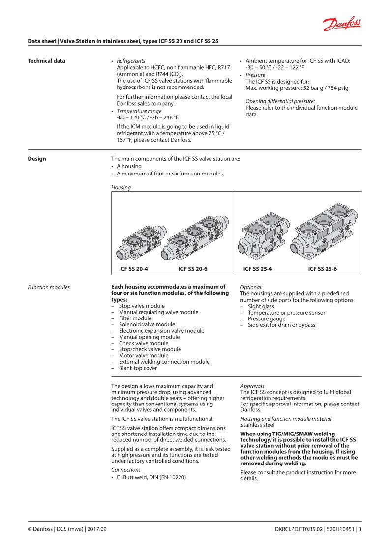
The main components of the ICF SS valve station are:
Each housing accommodates a maximum of four or six function modules, of the following types:– Stop valve module– Manual regulating valve module– Filter module– Solenoid valve module– Electronic expansion valve module– Manual opening module– Check valve module– Stop/check valve module– Motor valve module – External welding connection module– Blank top cover
Optional:The housings are supplied with a predefined number of side ports for the following options:– Sight glass – Temperature or pressure sensor – Pressure gauge – Side exit for drain or bypass.
Housing
Function modules
• A housing • A maximum of four or six function modules
ICF SS 20-4 ICF SS 20-6 ICF SS 25-4 ICF SS 25-6
Data sheet | Valve Station in stainless steel, types ICF SS 20 and ICF SS 25
DKRCI.PD.FT0.B5.02 | 520H10451 | 4© Danfoss | DCS (mwa) | 2017.09
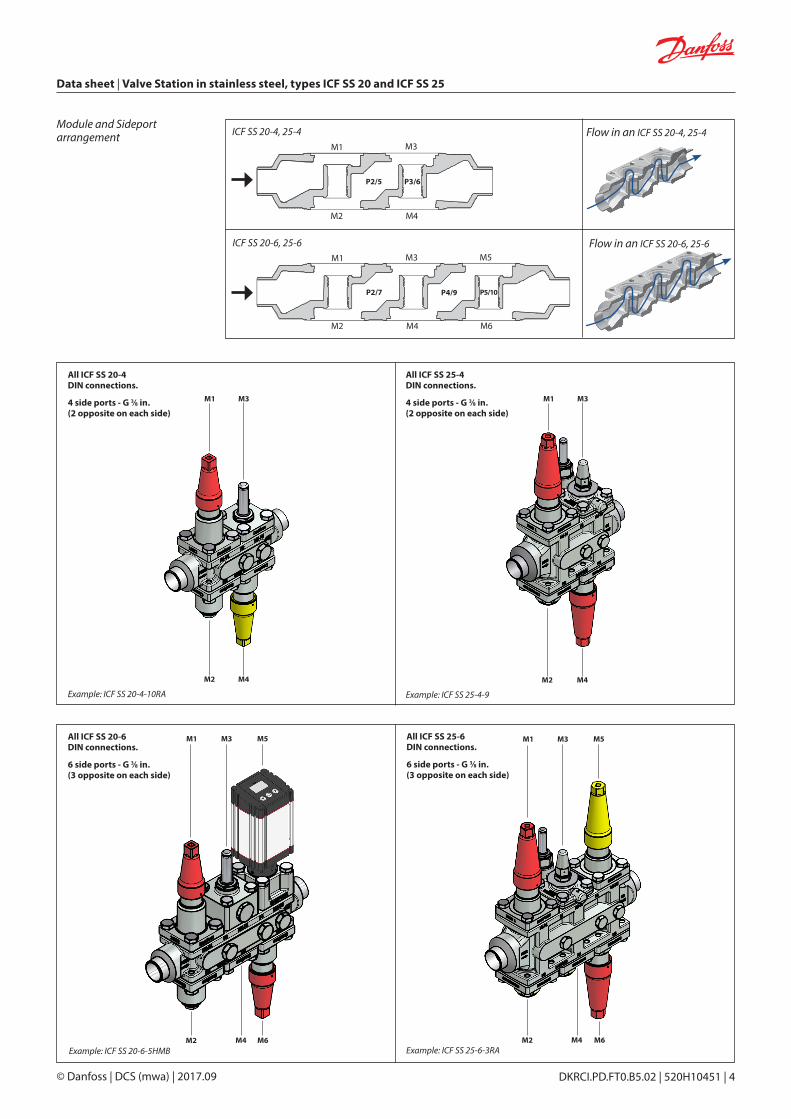
Module and Sideport arrangement
ICF SS 20-6, 25-6
P2/5 P3/6
P2/7 P4/9 P5/10
M1
M2
M3
M4
M5
M6
ICF SS 20-4, 25-4M1
M2
M3
M4
Flow in an ICF SS 20-4, 25-4
Flow in an ICF SS 20-6, 25-6
Example: ICF SS 25-6-3RAExample: ICF SS 20-6-5HMB
All ICF SS 20-6 DIN connections.
6 side ports - G 3⁄8 in. (3 opposite on each side)
All ICF SS 25-6 DIN connections.
6 side ports - G 3⁄8 in.(3 opposite on each side)
Example: ICF SS 20-4-10RA
All ICF SS 20-4 DIN connections.
4 side ports - G 3⁄8 in.(2 opposite on each side)
Example: ICF SS 25-4-9
All ICF SS 25-4 DIN connections.
4 side ports - G 3⁄8 in. (2 opposite on each side)
DKRCI.PD.FT0.B5.02 | 520H10451 | 5© Danfoss | DCS (mwa) | 2017.09
Data sheet | Valve Station in stainless steel, types ICF SS 20 and ICF SS 25
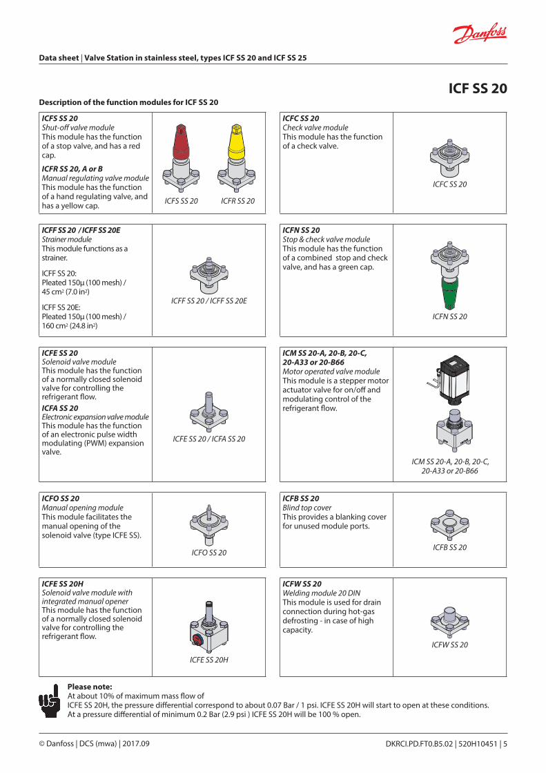
ICFS SS 20Shut-off valve moduleThis module has the function of a stop valve, and has a red cap.
ICFR SS 20, A or BManual regulating valve module This module has the function of a hand regulating valve, and has a yellow cap.
ICFC SS 20Check valve module This module has the function of a check valve.
ICFC SS 20
ICFF SS 20 / ICFF SS 20EStrainer module This module functions as a strainer.
ICFF SS 20:Pleated 150µ (100 mesh) / 45 cm2 (7.0 in2)
ICFF SS 20E:Pleated 150μ (100 mesh) / 160 cm2 (24.8 in2)
ICFF SS 20 / ICFF SS 20E
ICFN SS 20Stop & check valve module This module has the function of a combined stop and check valve, and has a green cap.
ICFN SS 20
ICFE SS 20Solenoid valve module This module has the function of a normally closed solenoid valve for controlling the refrigerant flow. ICFA SS 20Electronic expansion valve module This module has the function of an electronic pulse width modulating (PWM) expansion valve.
ICFE SS 20 / ICFA SS 20
ICM SS 20-A, 20-B, 20-C, 20-A33 or 20-B66Motor operated valve module This module is a stepper motor actuator valve for on/off and modulating control of the refrigerant flow.
ICM SS 20-A, 20-B, 20-C, 20-A33 or 20-B66
ICFO SS 20Manual opening module This module facilitates the manual opening of the solenoid valve (type ICFE SS).
ICFO SS 20
ICFB SS 20Blind top cover This provides a blanking cover for unused module ports.
ICFB SS 20
ICFE SS 20HSolenoid valve module with integrated manual opener This module has the function of a normally closed solenoid valve for controlling the refrigerant flow.
ICFE SS 20H
ICFW SS 20Welding module 20 DIN This module is used for drain connection during hot-gas defrosting - in case of high capacity.
ICFW SS 20
Description of the function modules for ICF SS 20ICF SS 20
Please note:At about 10% of maximum mass flow of ICFE SS 20H, the pressure differential correspond to about 0.07 Bar / 1 psi. ICFE SS 20H will start to open at these conditions.At a pressure differential of minimum 0.2 Bar (2.9 psi ) ICFE SS 20H will be 100 % open.
ICFS SS 20 ICFR SS 20
Data sheet | Valve Station in stainless steel, types ICF SS 20 and ICF SS 25
DKRCI.PD.FT0.B5.02 | 520H10451 | 6© Danfoss | DCS (mwa) | 2017.09
ICFS SS 25Shut-off valve module This module has the function of a stop valve, and has a red cap.
ICFS SS 25
ICFN SS 25Stop & check valve module This module has the function of a combined stop and check valve, and has a green cap.
ICFN SS 25
ICFR SS 25, A or BManual regulating valve module This module has the function of a hand regulating valve, and has a yellow cap.
ICFR SS 25
ICM SS 25-A or BMotor operated valve module This module is a stepper motor actuator valve for on/off and modulating control of the refrigerant flow.
ICM SS 25-A or B
ICFF SS 25 Strainer module This module functions as a strainer.
ICFF SS 25:Pleated 150µ (100 mesh) / 160 cm2 (24.8 in2)
ICFF SS 25E:Pleated 150μ (100 mesh) / 330 cm2 (51.2 in2)
ICFF SS 25 / ICFF SS 25E
ICFB SS 25Blind top cover This provides a blanking cover for unused module ports.
ICFB SS 25
ICFE SS 25Solenoid valve module This module has the function of a normally closed solenoid valve for controlling the refrigerant flow.
It has a built-in manual opening function.
ICFE SS 25
ICFC SS 25Check valve module This module has the function of a check valve.
ICFC SS 25
ICFW SS 25Welding module, 25 DIN This module is used for drain connection during hot-gas defrosting - in case of high capacity.
ICFW SS 25
Description of the function modules for ICF SS 25ICF SS 25
Please note:At about 10% of maximum mass flow of ICFE SS 25, the pressure differential correspond to about 0.07 Bar / 1 psi. ICFE SS 25 will start to open at these conditions.
At a pressure differential of minimum 0.2 Bar (2.9 psi ) ICFE SS 25 will be 100 % open.
DKRCI.PD.FT0.B5.02 | 520H10451 | 7© Danfoss | DCS (mwa) | 2017.09
Data sheet | Valve Station in stainless steel, types ICF SS 20 and ICF SS 25
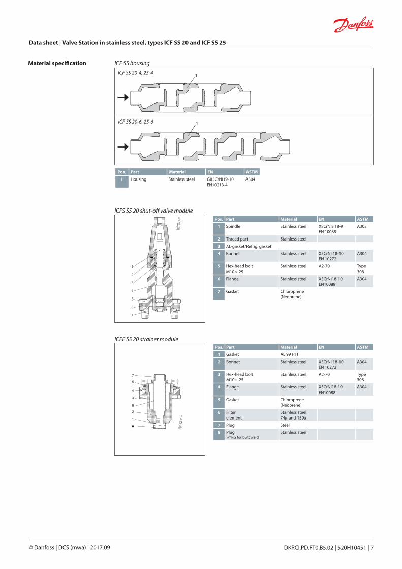
Material specification
Pos. Part Material EN ASTM
1 Housing Stainless steel GX5CrNi19-10 EN10213-4
A304
ICFS SS 20 shut-off valve modulePos. Part Material EN ASTM
1 Spindle Stainless steel X8CrNiS 18-9EN 10088
A303
2 Thread part Stainless steel
3 AL-gasket/Refrig. gasket
4 Bonnet Stainless steel X5CrNi 18-10 EN 10272
A304
5 Hex-head bolt M10 × 25
Stainless steel A2-70 Type 308
6 Flange Stainless steel X5CrNi18-10EN10088
A304
7 Gasket Chloroprene (Neoprene)
ICF SS 20-6, 25-6
ICF SS 20-4, 25-4 1
1
ICF SS housing
ICFF SS 20 strainer modulePos. Part Material EN ASTM
1 Gasket AL 99 F11
2 Bonnet Stainless steel X5CrNi 18-10 EN 10272
A304
3 Hex-head boltM10 × 25
Stainless steel A2-70 Type 308
4 Flange Stainless steel X5CrNi18-10EN10088
A304
5 Gasket Chloroprene (Neoprene)
6 Filter element
Stainless steel74μ and 150μ
7 Plug Steel
8 Plug ¼” RG for butt-weld
Stainless steel
Data sheet | Valve Station in stainless steel, types ICF SS 20 and ICF SS 25
DKRCI.PD.FT0.B5.02 | 520H10451 | 8© Danfoss | DCS (mwa) | 2017.09
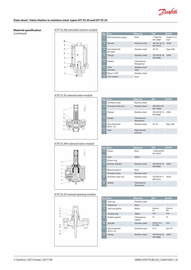
Material specification(continued)
ICFE SS 20 solenoid valve modulePos. Part Material EN ASTM
1 Armature tube Stainless steel
2 Armature tube nut Stainless steel X8CrNiS18-9EN 10088
3 Flange Stainless steel X5CrNi18-10EN10088
A304
4 Gasket Chloroprene (Neoprene)
5 Hex-Head boltM10 × 25
Stainless steel A2-70 Type 308
6 Seat High density polymer
ICFF SS 20E extended strainer modulePos. Part Material EN ASTM
1 Dirt protection plug Steel 11SMn30 EN 10087
Grade 1213 A29
2 Bonnet Stainless steel X5CrNi 18-10 EN 10272
A304
3 Hex-head boltM12x80
Stainless steel A2-70 Type 308
4 Flange Stainless steel X5CrNi18-10EN10088
A304
5 Gasket Chloroprene (Neoprene)
6 Filter element
Stainless steel250μ
7 Plug 3/8” NPT Stainless steel
8 Filter adaptor Steel
ICFE SS 20H solenoid valve modulePos. Part Material EN ASTM
1 Piston Steel 11SMn30 ENEN 10025
2 Seat Teflon
3 Piston ring
4 Bonnet cylinder Stainless steel X5CrNi18-10EN10088
A304
5 Manual opener Steel
6 Armature tube Stainless steel
7 Armature tube nut Stainless steel X2CrNi19-11EN10216
A320
8 Gasket Chloroprene (Neoprene)
ICFO SS 20 manual opening modulePos. Part Material EN ASTM
1 Seal cap Stainless steel
2 Gland nut Steel
3 Seal cap gasket Nylon Polyamid A6
Polyamid PA6
4 Sealing ring Teflon PTFE PTFE
5 Rubber gasket Chloroprene rubber
CR CR
6 Spindle Stainless steel X8CrNiS 18-9 EN 10088
A303
7 Hex-head bolt M10 × 25
Stainless steel A2-70 Type 308
8 Flange Stainless steel X5CrNi18-10EN10088
A304
DKRCI.PD.FT0.B5.02 | 520H10451 | 9© Danfoss | DCS (mwa) | 2017.09
Data sheet | Valve Station in stainless steel, types ICF SS 20 and ICF SS 25
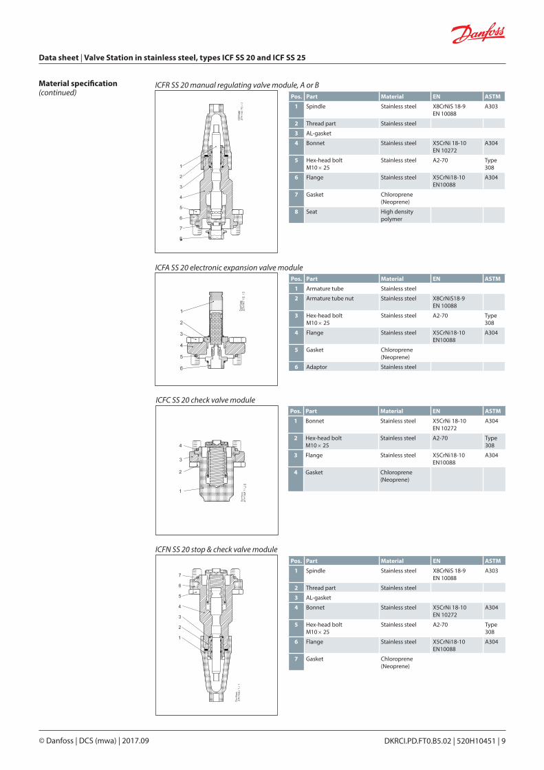
Material specification(continued)
ICFR SS 20 manual regulating valve module, A or BPos. Part Material EN ASTM
1 Spindle Stainless steel X8CrNiS 18-9EN 10088
A303
2 Thread part Stainless steel
3 AL-gasket
4 Bonnet Stainless steel X5CrNi 18-10 EN 10272
A304
5 Hex-head boltM10 × 25
Stainless steel A2-70 Type 308
6 Flange Stainless steel X5CrNi18-10EN10088
A304
7 Gasket Chloroprene (Neoprene)
8 Seat High density polymer
ICFA SS 20 electronic expansion valve modulePos. Part Material EN ASTM
1 Armature tube Stainless steel
2 Armature tube nut Stainless steel X8CrNiS18-9EN 10088
3 Hex-head bolt M10 × 25
Stainless steel A2-70 Type 308
4 Flange Stainless steel X5CrNi18-10EN10088
A304
5 Gasket Chloroprene (Neoprene)
6 Adaptor Stainless steel
ICFC SS 20 check valve modulePos. Part Material EN ASTM
1 Bonnet Stainless steel X5CrNi 18-10 EN 10272
A304
2 Hex-head boltM10 × 25
Stainless steel A2-70 Type 308
3 Flange Stainless steel X5CrNi18-10EN10088
A304
4 Gasket Chloroprene (Neoprene)
ICFN SS 20 stop & check valve modulePos. Part Material EN ASTM
1 Spindle Stainless steel X8CrNiS 18-9EN 10088
A303
2 Thread part Stainless steel
3 AL-gasket
4 Bonnet Stainless steel X5CrNi 18-10 EN 10272
A304
5 Hex-head boltM10 × 25
Stainless steel A2-70 Type 308
6 Flange Stainless steel X5CrNi18-10EN10088
A304
7 Gasket Chloroprene (Neoprene)
Data sheet | Valve Station in stainless steel, types ICF SS 20 and ICF SS 25
DKRCI.PD.FT0.B5.02 | 520H10451 | 10© Danfoss | DCS (mwa) | 2017.09
Material specification(continued)
ICM SS 20-A, 20-B, 20-C, 20-A33 or 20-B66 motor valve modulePos. Part Material EN ASTM
1 Adapter Stainless steel X5CrNi18-10EN 10088
A240
2 Hex-head boltM10 × 55
Stainless steel A2-70 Type 308
3 O-ring Chloroprene
4 Bonnet Stainless steel X5CrNi 18-10 EN 10088
A304
5 Gasket Chloroprene (Neoprene)
6 Seat High density polymer
Pos. Part Material EN ASTM
1 Hex-head boltM10 × 25
Stainless Steel A2-70 Type 308
2 Flange Stainless steel X5CrNi18-10EN10088
A304
3 Gasket Chloroprene (Neoprene)
ICFB SS 20 blank top cover
Pos. Part Material EN ASTM
1 Hex-head boltM10 × 25
Stainless Steel A2-70 Type 308
2 Flange Stainless steel X5CrNi18-10EN10088
A304
3 Gasket Chloroprene (Neoprene)
4 Weld connection Stainless Steel
ICFW SS 20D welding module, 20 DIN
ICFF SS 25 strainer modulePos. Part Material EN ASTM
1 Al. Gasket AL 99 F11
2 Bonnet Stainless steel X5CrNi 18-10 EN 10272
A304
3 Hex-head boltM12 × 30
Stainless steel A2-70 Type 308
4 Flange Stainless steel X5CrNi18-10EN10088
A304
5 Gasket Fiber non asbestos
6 Filter element
Stainless steel150μ
7 Plug ¼” RG for butt-weld
Stainless steel
ICFS SS 25 shut-off valve modulePos. Part Material EN ASTM
1 Spindle Stainless steel X8CrNiS 18-9EN 10088
A303
2 Thread part Stainless steel
3 O-ring Chloroprene
4 Bonnet Stainless steel X5CrNi 18-10 EN 10272
A304
5 Hex-head boltM12 × 30
Stainless steel A2-70 Type 308
6 Flange Stainless steel X5CrNi18-10EN10088
A304
7 Gasket Fiber non asbestos
DKRCI.PD.FT0.B5.02 | 520H10451 | 11© Danfoss | DCS (mwa) | 2017.09
Data sheet | Valve Station in stainless steel, types ICF SS 20 and ICF SS 25
Material specification(continued)
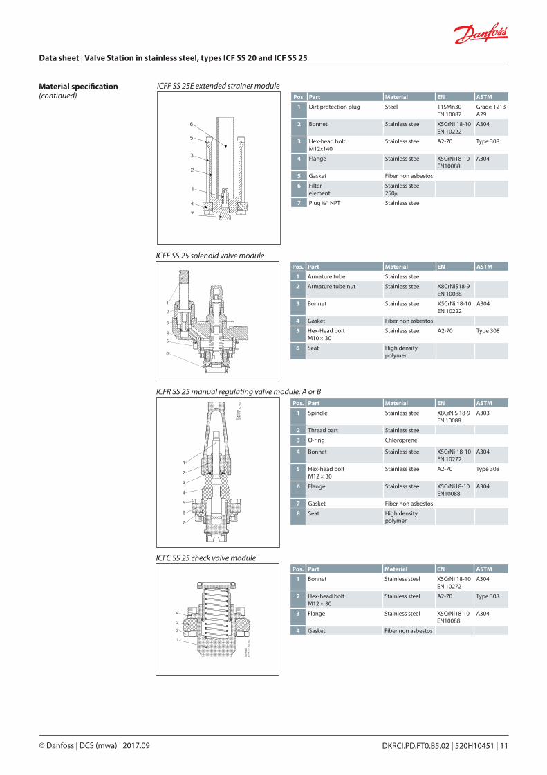
ICFE SS 25 solenoid valve modulePos. Part Material EN ASTM
1 Armature tube Stainless steel
2 Armature tube nut Stainless steel X8CrNiS18-9EN 10088
3 Bonnet Stainless steel X5CrNi 18-10 EN 10222
A304
4 Gasket Fiber non asbestos
5 Hex-Head boltM10 × 30
Stainless steel A2-70 Type 308
6 Seat High density polymer
ICFC SS 25 check valve modulePos. Part Material EN ASTM
1 Bonnet Stainless steel X5CrNi 18-10 EN 10272
A304
2 Hex-head boltM12 × 30
Stainless steel A2-70 Type 308
3 Flange Stainless steel X5CrNi18-10EN10088
A304
4 Gasket Fiber non asbestos
ICFR SS 25 manual regulating valve module, A or BPos. Part Material EN ASTM
1 Spindle Stainless steel X8CrNiS 18-9EN 10088
A303
2 Thread part Stainless steel
3 O-ring Chloroprene
4 Bonnet Stainless steel X5CrNi 18-10 EN 10272
A304
5 Hex-head boltM12 × 30
Stainless steel A2-70 Type 308
6 Flange Stainless steel X5CrNi18-10EN10088
A304
7 Gasket Fiber non asbestos
8 Seat High density polymer
ICFF SS 25E extended strainer modulePos. Part Material EN ASTM
1 Dirt protection plug Steel 11SMn30 EN 10087
Grade 1213 A29
2 Bonnet Stainless steel X5CrNi 18-10 EN 10222
A304
3 Hex-head boltM12x140
Stainless steel A2-70 Type 308
4 Flange Stainless steel X5CrNi18-10EN10088
A304
5 Gasket Fiber non asbestos
6 Filter element
Stainless steel250μ
7 Plug 3/8” NPT Stainless steel
Data sheet | Valve Station in stainless steel, types ICF SS 20 and ICF SS 25
DKRCI.PD.FT0.B5.02 | 520H10451 | 12© Danfoss | DCS (mwa) | 2017.09
Material specification(continued)
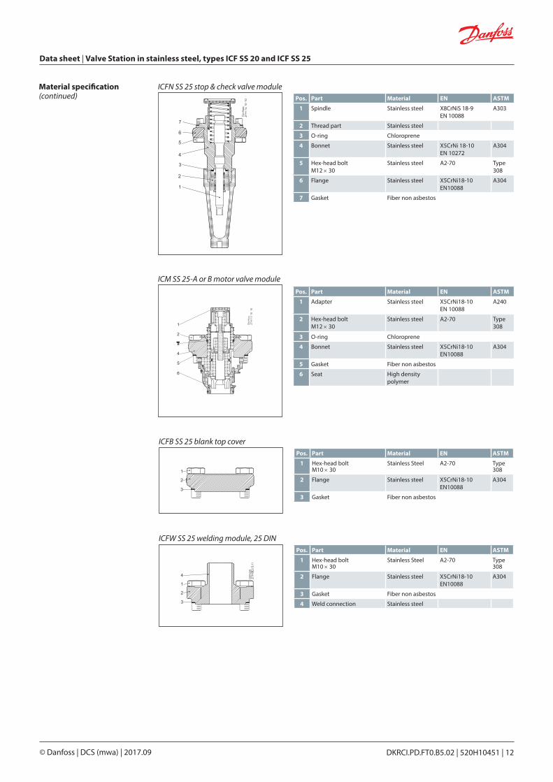
Pos. Part Material EN ASTM
1 Hex-head boltM10 × 30
Stainless Steel A2-70 Type 308
2 Flange Stainless steel X5CrNi18-10EN10088
A304
3 Gasket Fiber non asbestos
ICFB SS 25 blank top cover
Pos. Part Material EN ASTM
1 Hex-head boltM10 × 30
Stainless Steel A2-70 Type 308
2 Flange Stainless steel X5CrNi18-10EN10088
A304
3 Gasket Fiber non asbestos
4 Weld connection Stainless steel
ICFW SS 25 welding module, 25 DIN
ICM SS 25-A or B motor valve modulePos. Part Material EN ASTM
1 Adapter Stainless steel X5CrNi18-10EN 10088
A240
2 Hex-head boltM12 × 30
Stainless steel A2-70 Type 308
3 O-ring Chloroprene
4 Bonnet Stainless steel X5CrNi18-10 EN10088
A304
5 Gasket Fiber non asbestos
6 Seat High density polymer
ICFN SS 25 stop & check valve modulePos. Part Material EN ASTM
1 Spindle Stainless steel X8CrNiS 18-9EN 10088
A303
2 Thread part Stainless steel
3 O-ring Chloroprene
4 Bonnet Stainless steel X5CrNi 18-10 EN 10272
A304
5 Hex-head boltM12 × 30
Stainless steel A2-70 Type 308
6 Flange Stainless steel X5CrNi18-10EN10088
A304
7 Gasket Fiber non asbestos
DKRCI.PD.FT0.B5.02 | 520H10451 | 13© Danfoss | DCS (mwa) | 2017.09
Data sheet | Valve Station in stainless steel, types ICF SS 20 and ICF SS 25
Code number selection To determine the correct ICF SS valve station follow steps 1 through 5.
Step 1 Determine application and function requirements: – Line: Pumped liquid, Liquid Injection, Hot gas defrost, Liquid DX etc. – Control: On/off solenoid valve, motorised valve – Defrost: Electric or hot gas
From the above determine the application reference number (see pages 14 and 17):
Step 2 Selection criteria - (Please use ICF SS calculation software) Download the software from: http://www.danfoss.com/BusinessAreas/RefrigerationAndAirConditioning/ IR+Software+Overview/IRSoftware.htm – Refrigerant – Capacity – Temperature – Circulation rate
From the above determine the valve station required, e.g.: ICF SS 20 complete with ICM SS 20-C
Step 3 Establish connection sizes and type – DIN butt-weld – 20 (¾ in.), 25 (1 in.), 32 (1 ¼ in.) or 40 (1 ½ in.)
Step 4 Establish code number (see pages 18 to 20)
Data sheet | Valve Station in stainless steel, types ICF SS 20 and ICF SS 25
DKRCI.PD.FT0.B5.02 | 520H10451 | 14© Danfoss | DCS (mwa) | 2017.09
ICFS SS ICFE SS ICFR SS
ICFF SSICFB SS
ICFS SS
To liquid separator
AKS 12
SVA
EKC 202
Evaporator
From liquid separator
Not all valves are shown. Not to be used for construction purposes.
Applications
Example of application: Liquid feed line
A valve combination for a flooded evaporatoroperating on/off from a thermostat and withelectric defrost is required. Manual override ofthe solenoid valve is requested. Common ICF SS configurations for this kind of application is shown here:
To facilitate selection of the right ICF SS valve station Danfoss has predefined and grouped a large number of code numbers matching common applications:
For specific identification of the different codes and flow capacity (Kv) please refer to ordering section.
Application # Sequence of functions
Liquid feed1 Liquid feed (No hotgas defrost) Stop Filter Solenoid Man Open Regul. Stop
2 Liquid feed Stop Filter Solenoid Man Open Regul. Stop/Check
3 Liquid feed Stop Filter Solenoid Check Regul. Stop
10 Liquid feed (No hotgas defrost) Stop Filter Solenoid Regul.
15 Liquid feed with external connection Stop Filter Solenoid Check Welding Regul.
Liquid injection5 Liquid injection (expansion) Stop Filter Solenoid Man Open Motor Stop
14 Liquid injection (expansion) Stop Filter Motor Stop
Hot gas defrost9 Hot gas defrost Stop Filter Solenoid Stop
Miscellaneous90 Multipurpose configurations
DKRCI.PD.FT0.B5.02 | 520H10451 | 15© Danfoss | DCS (mwa) | 2017.09
Data sheet | Valve Station in stainless steel, types ICF SS 20 and ICF SS 25
ICFS SS ICFE SS ICM
ICFF SS
ICFB SS
ICFS SS
To compressor suction line
SVA
SFV SFV
DSV
SVA AKS 4100
SNV
AKS 38
EKE 347
From receiver
From evaporator
SVA
SVASVASVA
To evaporator
SNV
LLG Liquid separator
Not all valves are shown. Not to be used for construction purposes.
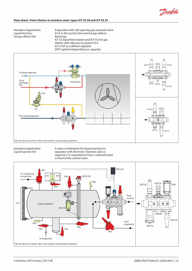
Example of application: Liquid feed line/ Hot gas defrost line
Evaporator with soft opening gas powered valveICLX in the suction line and hot gas defrost featuring:ICF SS liquid feed station and ICF SS Hot gasstation with side port to power ICLX. ICS+CVP as a defrost regulator(OFV optional depending on capacity).
ICFS SSICFE SS
ICFR SS
ICFF SS ICFO SSICFN SS
ICFS SS ICFE SS
ICFF SSICFF SS
ICLX/GPLX
ICS
CVP
To liquid separator
From discharge line
From liquid separator
Not all valves are shown. Not to be used for construction purposes.
Example of application: Liquid injection line
A valve combination for liquid injection toseparator with electronic injection valve isrequired. It is requested to have a solenoid valvein front of the control valve.
Data sheet | Valve Station in stainless steel, types ICF SS 20 and ICF SS 25
DKRCI.PD.FT0.B5.02 | 520H10451 | 16© Danfoss | DCS (mwa) | 2017.09
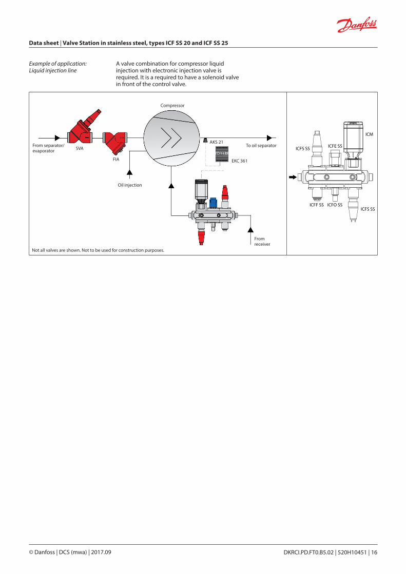
Example of application: Liquid injection line
A valve combination for compressor liquidinjection with electronic injection valve isrequired. It is a required to have a solenoid valvein front of the control valve.
ICFS SS ICFE SS
ICM
ICFF SS ICFO SSICFS SS
Compressor
From separator/evaporator SVA
FIA
AKS 21
EKC 361
To oil separator
From receiver
Oil injection
Not all valves are shown. Not to be used for construction purposes.
DKRCI.PD.FT0.B5.02 | 520H10451 | 17© Danfoss | DCS (mwa) | 2017.09
Data sheet | Valve Station in stainless steel, types ICF SS 20 and ICF SS 25
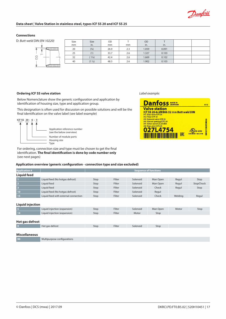
Below Nomenclature show the generic configuration and application by identification of housing size, type and application group.
This designation is often used for discussion on possible solutions and will be the final identification on the valve label (see label example)
ICF SS 20 - 6 - 3
Type
Number of module ports
Application reference number (see the below overview)
Housing size
Application overview (generic configuration - connection type and size excluded)
Ordering ICF SS valve station
For ordering, connection size and type must be chosen to get the final identification. The final identification is done by code number only (see next pages)
Application # Sequence of functions
Liquid feed1 Liquid feed (No hotgas defrost) Stop Filter Solenoid Man Open Regul. Stop
2 Liquid feed Stop Filter Solenoid Man Open Regul. Stop/Check
3 Liquid feed Stop Filter Solenoid Check Regul. Stop
10 Liquid feed (No hotgas defrost) Stop Filter Solenoid Regul.
15 Liquid feed with external connection Stop Filter Solenoid Check Welding Regul.
Liquid injection5 Liquid injection (expansion) Stop Filter Solenoid Man Open Motor Stop
14 Liquid injection (expansion) Stop Filter Motor Stop
Hot gas defrost9 Hot gas defrost Stop Filter Solenoid Stop
Miscellaneous90 Multipurpose configurations
Label example:
Connections
D: Butt-weld DIN (EN 10220) Sizemm
Sizein.
ODmm
Tmm
ODin.
Tin.
20 (¾) 26.9 2.3 1.059 0.091
25 (1) 33.7 2.6 1.327 0.103
32 ( 1¼) 42.4 2.6 1.669 0.102
40 (1 ½) 48.3 2.6 1.902 0.103
Data sheet | Valve Station in stainless steel, types ICF SS 20 and ICF SS 25
DKRCI.PD.FT0.B5.02 | 520H10451 | 18© Danfoss | DCS (mwa) | 2017.09
ICAD and coils are not included and must be ordered separately.Please Note:When used in systems with CO2, the o-rings on the ICM module can swell (grow). At service, it is therefore recommended to install new o-rings, before the ICM function module is re-installed in the ICF SS valve body. ICAD and coils are not included and must be ordered separately.
Application 1: Liquid feed (no hot gas defrost)Type # of
modulesAppl.
#Connection size Connection type Module location Kv
totalWeight Code
number[in.] [mm] M1 M2 M3 M4 M5 M6 kg lbs
ICF SS 20 6 1RA 3/4 20 Butt-weld DIN-EN 10220 D ICFS 20 ICFF 20 ICFE 20 ICFO 20 ICFR 20A ICFS 20 2.1 9.5 20.9 027L4700
ICF SS 20 6 1RA 1 25 Butt-weld DIN-EN 10220 D ICFS 20 ICFF 20 ICFE 20 ICFO 20 ICFR 20A ICFS 20 2.1 9.7 21.3 027L4701
Liquid feed
Application 2: Liquid feedType # of
ModulesAppl.
#Connection size Connection type Module location Kv
totalWeight Code
number[in.] [mm] M1 M2 M3 M4 M5 M6 kg lbs
ICF SS 20 6 2RA 3/4 20 Butt-weld DIN-EN 10220 D ICFS 20 ICFF 20 ICFE 20 ICFO 20 ICFR 20A ICFN 20 2.4 10.0 22.1 027L3428
ICF SS 20 6 2RA 1 25 Butt-weld DIN-EN 10220 D ICFS 20 ICFF 20E ICFE 20 ICFO 20 ICFR 20A ICFN 20 2.4 10.0 22.1 027L3445
ICF SS 20 6 2RA 1 25 Butt-weld DIN-EN 10220 D ICFS 20 ICFF 20 ICFE 20 ICFO 20 ICFR 20A ICFN 20 2.1 9.7 21.3 027L4758
ICF SS 20 6 2HRB 11/4 32 Butt-weld DIN-EN 10220 D ICFS 20 ICFF 20 ICFE 20H ICFB 20 ICFR 20B ICFN 20 2.6 9.2 20.2 027L4759
ICF SS 25 6 2RB 11/4 32 Butt-weld DIN-EN 10220 D ICFS 25 ICFF 25 ICFE 25 ICFB 25 ICFR 25B ICFN 25 8.5 23.9 52.6 027L4766
Application 3: Liquid feedType # of
ModulesAppl.
#Connection size Connection type Module location Kv
totalWeight Code
number[in.] [mm] M1 M2 M3 M4 M5 M6 kg lbs
ICF SS 20 6 3RA 3/4 20 Butt-weld DIN-EN 10220 D ICFS 20 ICFF 20 ICFE 20 ICFC 20 ICFR 20A ICFS 20 2.1 9.6 21.1 027L4702
ICF SS 20 6 3RA 1 25 Butt-weld DIN-EN 10220 D ICFS 20 ICFF 20 ICFE 20 ICFC 20 ICFR 20A ICFS 20 2.1 9.7 21.3 027L4703
ICF SS 20 6 3HRA 1 25 Butt-weld DIN-EN 10220 D ICFS 20 ICFF 20 ICFE 20H ICFC 20 ICFR 20A ICFS 20 2.3 10.6 23.3 027L4717
ICF SS 25 6 3RA 1 25 Butt-weld DIN-EN 10220 D ICFS 25 ICFF 25 ICFE 25 ICFC 25 ICFR 25A ICFS 25 5.3 23.4 51.5 027L4724
ICF SS 25 6 3RA 11/4 32 Butt-weld DIN-EN 10220 D ICFS 25 ICFF 25 ICFE 25 ICFC 25 ICFR 25A ICFS 25 5.3 23.2 51.0 027L4760
ICF SS 25 6 3RB 11/4 32 Butt-weld DIN-EN 10220 D ICFS 25 ICFF 25 ICFE 25 ICFC 25 ICFR 25B ICFS 25 7.2 23.8 52.4 027L4725
ICF SS 25 6 3RB 11/2 40 Butt-weld DIN-EN 10220 D ICFS 25 ICFF 25 ICFE 25 ICFC 25 ICFR 25B ICFS 25 7.2 24.0 52.8 027L4761
ICF SS 25 6 3RB 11/2 40 Butt-weld DIN-EN 10220 D ICFS 25 ICFF 25E ICFE 25 ICFC 25 ICFR 25B ICFS 25 8.5 24.7 54.3 027L4191
Application 10: Liquid feed (no hot gas defrost)Type # of
ModulesAppl.
#Connection size Connection type Module location Kv
totalWeight Code
number[in.] [mm] M1 M2 M3 M4 kg lbs
ICF SS 20 4 10RA 3/4 20 Butt-weld DIN-EN 10220 D ICFS 20 ICFF 20 ICFE 20 ICFR 20B 2.6 7.4 16.2 027L3440
ICF SS 20 4 10RA 1 25 Butt-weld DIN-EN 10220 D ICFS 20 ICFF 20 ICFE 20 ICFR 20A 2.3 7.2 15.8 027L4709
ICF SS 25 4 10RA 1 25 Butt-weld DIN-EN 10220 D ICFS 25 ICFF 25 ICFE 25 ICFR 25A 5.5 15.9 35.0 027L4731
ICF SS 25 4 10RB 11/4 32 Butt-weld DIN-EN 10220 D ICFS 25 ICFF 25 ICFE 25 ICFR 25B 7.9 15.4 33.9 027L4732
ICF SS 25 4 10RA 1 25 Butt-weld DIN-EN 10220 D ICFS 25 ICFF 25E ICFE 25 ICFR 25A 5.5 16.2 35.7 027L4590
Application 15: Liquid feed with external connectionType # of
ModulesAppl.
#Connection size Connection type Module location Kv
totalWeight Code
number[in.] [mm] M1 M2 M3 M4 M5 M6 kg lbs
ICF SS 25 6 15RA 1 25 Butt-weld DIN-EN 10220 D ICFS 25 ICFF 25 ICFE 25 ICFC 25 ICFW 25D ICFR 25A 5.3 21.8 48.0 027L4733
ICF SS 25 6 15RB 11/4 32 Butt-weld DIN-EN 10220 D ICFS 25 ICFF 25 ICFE 25 ICFC 25 ICFW 25D ICFR 25B 7.3 22.7 49.9 027L4734
DKRCI.PD.FT0.B5.02 | 520H10451 | 19© Danfoss | DCS (mwa) | 2017.09
Data sheet | Valve Station in stainless steel, types ICF SS 20 and ICF SS 25
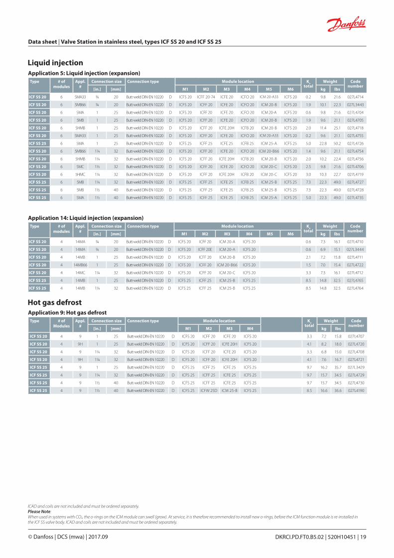
Liquid injectionApplication 5: Liquid injection (expansion)
Type # of modules
Appl.#
Connection size Connection type Module location Kvtotal
Weight Code number
[in.] [mm] M1 M2 M3 M4 M5 M6 kg lbs
ICF SS 20 6 5MA33 3/4 20 Butt-weld DIN-EN 10220 D ICFS 20 ICFF 20-74 ICFE 20 ICFO 20 ICM 20-A33 ICFS 20 0.2 9.8 21.6 027L4714
ICF SS 20 6 5MB66 3/4 20 Butt-weld DIN-EN 10220 D ICFS 20 ICFF 20 ICFE 20 ICFO 20 ICM 20-B ICFS 20 1.9 10.1 22.3 027L3443
ICF SS 20 6 5MA 1 25 Butt-weld DIN-EN 10220 D ICFS 20 ICFF 20 ICFE 20 ICFO 20 ICM 20-A ICFS 20 0.6 9.8 21.6 027L4704
ICF SS 20 6 5MB 1 25 Butt-weld DIN-EN 10220 D ICFS 20 ICFF 20 ICFE 20 ICFO 20 ICM 20-B ICFS 20 1.9 9.6 21.1 027L4705
ICF SS 20 6 5HMB 1 25 Butt-weld DIN-EN 10220 D ICFS 20 ICFF 20 ICFE 20H ICFB 20 ICM 20-B ICFS 20 2.0 11.4 25.1 027L4718
ICF SS 20 6 5MA33 1 25 Butt-weld DIN-EN 10220 D ICFS 20 ICFF 20 ICFE 20 ICFO 20 ICM 20-A33 ICFS 20 0.2 9.6 21.1 027L4755
ICF SS 25 6 5MA 1 25 Butt-weld DIN-EN 10220 D ICFS 25 ICFF 25 ICFE 25 ICFB 25 ICM 25-A ICFS 25 5.0 22.8 50.2 027L4726
ICF SS 20 6 5MB66 11/4 32 Butt-weld DIN-EN 10220 D ICFS 20 ICFF 20 ICFE 20 ICFO 20 ICM 20-B66 ICFS 20 1.4 9.6 21.1 027L4754
ICF SS 20 6 5HMB 11/4 32 Butt-weld DIN-EN 10220 D ICFS 20 ICFF 20 ICFE 20H ICFB 20 ICM 20-B ICFS 20 2.0 10.2 22.4 027L4756
ICF SS 20 6 5MC 11/2 32 Butt-weld DIN-EN 10220 D ICFS 20 ICFF 20 ICFE 20 ICFO 20 ICM 20-C ICFS 20 2.5 9.8 21.6 027L4706
ICF SS 20 6 5HMC 11/4 32 Butt-weld DIN-EN 10220 D ICFS 20 ICFF 20 ICFE 20H ICFB 20 ICM 20-C ICFS 20 3.0 10.3 22.7 027L4719
ICF SS 25 6 5MB 11/4 32 Butt-weld DIN-EN 10220 D ICFS 25 ICFF 25 ICFE 25 ICFB 25 ICM 25-B ICFS 25 7.3 22.3 49.0 027L4727
ICF SS 25 6 5MB 11/2 40 Butt-weld DIN-EN 10220 D ICFS 25 ICFF 25 ICFE 25 ICFB 25 ICM 25-B ICFS 25 7.3 22.3 49.0 027L4728
ICF SS 25 6 5MA 11/2 40 Butt-weld DIN-EN 10220 D ICFS 25 ICFF 25 ICFE 25 ICFB 25 ICM 25-A ICFS 25 5.0 22.3 49.0 027L4735
Application 14: Liquid injection (expansion)Type # of
modulesAppl.
#Connection size Connection type Module location Kv
totalWeight Code
number[in.] [mm] M1 M2 M3 M4 M5 M6 kg lbs
ICF SS 20 4 14MA 3/4 20 Butt-weld DIN-EN 10220 D ICFS 20 ICFF 20 ICM 20-A ICFS 20 0.6 7.3 16.1 027L4710
ICF SS 20 4 14MA 3/4 20 Butt-weld DIN-EN 10220 D ICFS 20 ICFF 20E ICM 20-A ICFS 20 0.6 6.9 15.1 027L3444
ICF SS 20 4 14MB 1 25 Butt-weld DIN-EN 10220 D ICFS 20 ICFF 20 ICM 20-B ICFS 20 2.1 7.2 15.8 027L4711
ICF SS 20 4 14MB66 1 25 Butt-weld DIN-EN 10220 D ICFS 20 ICFF 20 ICM 20-B66 ICFS 20 1.5 7.0 15.4 027L4722
ICF SS 20 4 14MC 11/4 32 Butt-weld DIN-EN 10220 D ICFS 20 ICFF 20 ICM 20-C ICFS 20 3.3 7.3 16.1 027L4712
ICF SS 25 4 14MB 1 25 Butt-weld DIN-EN 10220 D ICFS 25 ICFF 25 ICM 25-B ICFS 25 8.5 14.8 32.5 027L4765
ICF SS 25 4 14MB 11/4 32 Butt-weld DIN-EN 10220 D ICFS 25 ICFF 25 ICM 25-B ICFS 25 8.5 14.8 32.5 027L4764
Application 9: Hot gas defrostType # of
ModulesAppl.
#Connection size Connection type Module location Kv
totalWeight Code
number[in.] [mm] M1 M2 M3 M4 kg lbs
ICF SS 20 4 9 1 25 Butt-weld DIN-EN 10220 D ICFS 20 ICFF 20 ICFE 20 ICFS 20 3.3 7.2 15.8 027L4707
ICF SS 20 4 9H 1 25 Butt-weld DIN-EN 10220 D ICFS 20 ICFF 20 ICFE 20H ICFS 20 4.1 8.2 18.0 027L4720
ICF SS 20 4 9 11/4 32 Butt-weld DIN-EN 10220 D ICFS 20 ICFF 20 ICFE 20 ICFS 20 3.3 6.8 15.0 027L4708
ICF SS 20 4 9H 11/4 32 Butt-weld DIN-EN 10220 D ICFS 20 ICFF 20 ICFE 20H ICFS 20 4.1 7.6 16.7 027L4721
ICF SS 25 4 9 1 25 Butt-weld DIN-EN 10220 D ICFS 25 ICFF 25 ICFE 25 ICFS 25 9.7 16.2 35.7 027L3429
ICF SS 25 4 9 11/4 32 Butt-weld DIN-EN 10220 D ICFS 25 ICFF 25 ICFE 25 ICFS 25 9.7 15.7 34.5 027L4729
ICF SS 25 4 9 11/2 40 Butt-weld DIN-EN 10220 D ICFS 25 ICFF 25 ICFE 25 ICFS 25 9.7 15.7 34.5 027L4730
ICF SS 25 4 9 11/2 40 Butt-weld DIN-EN 10220 D ICFS 25 ICFW 25D ICM 25-B ICFS 25 8.5 16.6 36.6 027L4190
Hot gas defrost
ICAD and coils are not included and must be ordered separately.Please Note:When used in systems with CO2, the o-rings on the ICM module can swell (grow). At service, it is therefore recommended to install new o-rings, before the ICM function module is re-installed in the ICF SS valve body. ICAD and coils are not included and must be ordered separately.
Data sheet | Valve Station in stainless steel, types ICF SS 20 and ICF SS 25
DKRCI.PD.FT0.B5.02 | 520H10451 | 20© Danfoss | DCS (mwa) | 2017.09
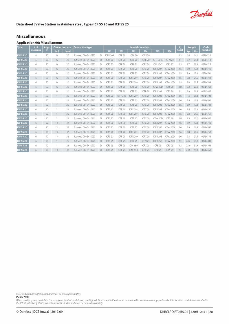
MiscellaneousApplication 90: MiscellaneousType # of
modulesAppl.
#Connection size Connection type Module location Kv
totalWeight Code
number[in.] [mm] M1 M2 M3 M4 M5 M6 kg lbs
ICF SS 20 4 90 3/4 20 Butt-weld DIN-EN 10220 D ICFR 20A ICFF 20 ICFA 20 ICFN 20 0.3 6.4 14.1 027L4716
ICF SS 20 6 90 3/4 20 Butt-weld DIN-EN 10220 D ICFS 20 ICFF 20 ICFE 20 ICFB 20 ICFR 20-A ICFN 20 2.1 9.7 21.3 027L4713
ICF SS 20 6 90 3/4 20 Butt-weld DIN-EN 10220 D ICFS 20 ICFF 20 ICFE 20 ICFC 20 ICM 20-C ICFS 20 2.5 9.7 21.3 027L4715
ICF SS 20 6 90 3/4 20 Butt-weld DIN-EN 10220 D ICFS 20 ICFF 20 ICFE 20 ICFC 20 ICFR 20A ICFW 20D 2.5 8.9 17.8 027L4740
ICF SS 20 6 90 3/4 20 Butt-weld DIN-EN 10220 D ICFS 20 ICFF 20 ICFE 20 ICFC 20 ICFR 20B ICFW 20D 2.5 8.9 17.8 027L4741
ICF SS 20 6 90 3/4 20 Butt-weld DIN-EN 10220 D ICFS 20 ICFF 20 ICFE 20H ICFC 20 ICFR 20A ICFW 20D 2.5 9.8 21.5 027L4748
ICF SS 20 6 90 3/4 20 Butt-weld DIN-EN 10220 D ICFS 20 ICFF 20 ICFE 20H ICFC 20 ICFR 20B ICFW 20D 2.5 9.8 21.5 027L4749
ICF SS 20 6 90 3/4 20 Butt-weld DIN-EN 10220 D ICFS 20 ICFF 20 ICFE 20 ICFC 20 ICFW 20D ICFS 20 2.8 9.3 20.6 027L4768
ICF SS 20 6 90 3/4 20 Butt-weld DIN-EN 10220 D ICFS 20 ICFF 20 ICFE 20 ICFB 20 ICFR 20A ICFS 20 2.1 9.9 21.8 027L3427
ICF SS 20 6 90 1 25 Butt-weld DIN-EN 10220 D ICFS 20 ICFF 20E ICFE 20H ICFC 20 ICFR 20B ICFW 20D 2.6 11.5 25.3 027L4723
ICF SS 20 6 90 1 25 Butt-weld DIN-EN 10220 D ICFS 20 ICFF 20 ICFE 20 ICFC 20 ICFR 20A ICFW 20D 2.6 8.9 17.8 027L4742
ICF SS 20 6 90 1 25 Butt-weld DIN-EN 10220 D ICFS 20 ICFF 20 ICFE 20 ICFC 20 ICFR 20B ICFW 20D 2.6 8.9 17.8 027L4743
ICF SS 20 6 90 1 25 Butt-weld DIN-EN 10220 D ICFS 20 ICFF 20 ICFE 20H ICFC 20 ICFR 20A ICFW 20D 2.6 9.8 21.5 027L4750
ICF SS 20 6 90 1 25 Butt-weld DIN-EN 10220 D ICFS 20 ICFF 20 ICFE 20H ICFC 20 ICFR 20B ICFW 20D 2.6 9.8 21.5 027L4751
ICF SS 20 6 90 1 25 Butt-weld DIN-EN 10220 D ICFS 20 ICFF 20 ICFE 20 ICFC 20 ICFW 20D ICFS 20 2.8 9.3 20.6 027L4767
ICF SS 20 6 90 11/4 32 Butt-weld DIN-EN 10220 D ICFS 20 ICFF 20 ICFE 20 ICFC 20 ICFR 20A ICFW 20D 2.6 8.9 17.8 027L4746
ICF SS 20 6 90 11/4 32 Butt-weld DIN-EN 10220 D ICFS 20 ICFF 20 ICFE 20 ICFC 20 ICFR 20B ICFW 20D 2.6 8.9 17.8 027L4747
ICF SS 20 6 90 11/4 32 Butt-weld DIN-EN 10220 D ICFS 20 ICFF 20 ICFE 20H ICFC 20 ICFR 20A ICFW 20D 2.6 9.8 21.5 027L4752
ICF SS 20 6 90 11/4 32 Butt-weld DIN-EN 10220 D ICFS 20 ICFF 20 ICFE 20H ICFC 20 ICFR 20B ICFW 20D 2.6 9.8 21.5 027L4753
ICF SS 25 6 90 1 25 Butt-weld DIN-EN 10220 D ICFS 25 ICFF 25 ICFE 25 ICFN 25 ICFR 25B ICFW 25D 7.3 24.2 53.2 027L4189
ICF SS 25 6 90 1 25 Butt-weld DIN-EN 10220 D ICFS 25 ICFF 25 ICM 25-A ICFC 25 ICFB 25 ICFS 25 5.2 23.6 51.9 027L4763
ICF SS 25 6 90 11/4 32 Butt-weld DIN-EN 10220 D ICFS 25 ICFF 25 ICM 25-B ICFC 25 ICFB 25 ICFS 25 7.7 23.6 51.9 027L4762
ICAD and coils are not included and must be ordered separately.Please Note:When used in systems with CO2, the o-rings on the ICM module can swell (grow). At service, it is therefore recommended to install new o-rings, before the ICM function module is re-installed in the ICF SS valve body. ICAD and coils are not included and must be ordered separately.
DKRCI.PD.FT0.B5.02 | 520H10451 | 21© Danfoss | DCS (mwa) | 2017.09
Data sheet | Valve Station in stainless steel, types ICF SS 20 and ICF SS 25
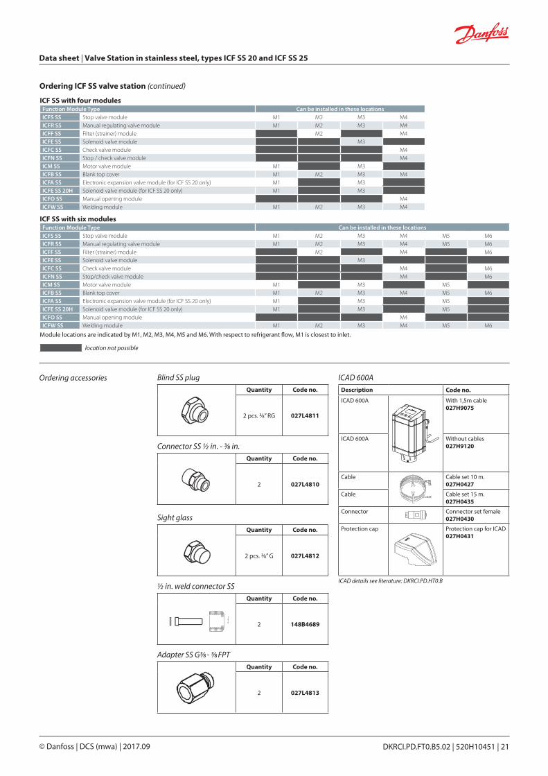
Ordering accessoriesQuantity Code no.
2 pcs. 3/8” RG 027L4811
Blind SS plug
Quantity Code no.
2 027L4810
Connector SS 1/2 in. - 3/8 in.
Quantity Code no.
2 pcs. 3/8” G 027L4812
Sight glass
ICAD 600A
Quantity Code no.
2 148B4689
1/2 in. weld connector SS
Description Code no.
ICAD 600A With 1,5m cable 027H9075
ICAD 600A Without cables 027H9120
Cable Cable set 10 m. 027H0427
Cable Cable set 15 m. 027H0435
Connector Connector set female027H0430
Protection cap Protection cap for ICAD027H0431
ICAD details see literature: DKRCI.PD.HT0.B
Ordering ICF SS valve station (continued)
location not possible
ICF SS with six modulesFunction Module Type Can be installed in these locationsICFS SS Stop valve module M1 M2 M3 M4 M5 M6ICFR SS Manual regulating valve module M1 M2 M3 M4 M5 M6ICFF SS Filter (strainer) module M2 M4 M6ICFE SS Solenoid valve module M3ICFC SS Check valve module M4 M6ICFN SS Stop/check valve module M4 M6ICM SS Motor valve module M1 M3 M5ICFB SS Blank top cover M1 M2 M3 M4 M5 M6ICFA SS Electronic expansion valve module (for ICF SS 20 only) M1 M3 M5ICFE SS 20H Solenoid valve module (for ICF SS 20 only) M1 M3 M5ICFO SS Manual opening module M4ICFW SS Welding module M1 M2 M3 M4 M5 M6
Module locations are indicated by M1, M2, M3, M4, M5 and M6. With respect to refrigerant flow, M1 is closest to inlet.
ICF SS with four modulesFunction Module Type Can be installed in these locationsICFS SS Stop valve module M1 M2 M3 M4ICFR SS Manual regulating valve module M1 M2 M3 M4ICFF SS Filter (strainer) module M2 M4ICFE SS Solenoid valve module M3ICFC SS Check valve module M4ICFN SS Stop / check valve module M4ICM SS Motor valve module M1 M3ICFB SS Blank top cover M1 M2 M3 M4ICFA SS Electronic expansion valve module (for ICF SS 20 only) M1 M3ICFE SS 20H Solenoid valve module (for ICF SS 20 only) M1 M3ICFO SS Manual opening module M4ICFW SS Welding module M1 M2 M3 M4
Quantity Code no.
2 027L4813
Adapter SS G3/8 - 3/8 FPT
Data sheet | Valve Station in stainless steel, types ICF SS 20 and ICF SS 25
DKRCI.PD.FT0.B5.02 | 520H10451 | 22© Danfoss | DCS (mwa) | 2017.09
Coils
Valve type
Voltage
V
Frequency
Hz
Code no.
Appen-dix
no.*)
Power con-
sumption
With 1 m3-core cable
IP 67
With terminal
box
IP 67
WithDIN
plugs**)
Direct current DC (can not be used for ICF SS 20 configurations with ICM module) Coil type I
Alternating current AC ICFE
12 50 018F6706 15 Holding:10 W21 VA
Inrush:44 VA
24 50 018F6257 018F6707 018F7358 16
220 – 230 50 018F6251 018F6701 018F7351 31
115 60 018F6260 018F6710 20
ICFE/ICFA
12 018F6856 01
20 W
24 018F6857 02
Alternating current AC
Valve typeVoltage
V
Frequency
Hz
Code no.
Appendix no.Indicates
voltage and frequency
Power consumption
With terminal box
IP 67
ICFE24 50 018F6807 16 Holding:
12 W26 VA
Inrush:55 VA
110 50 018F6811 22
220 – 230 50 018F6801 31
Special coils for ICFE (can not be used for ICF SS 20 configurations with ICM module)
For other coil types please refer to the technical leaflets for EVRA or AKVA valves.
Ordering accessories(continued) Description Code no.
SNV-SS for ICF SS 20/SS 25 DIN butt weld connection.
Side connection: G ½ in.Bottom connection: G ½ in.
Included:Adapter SS (G ½ in. - G 3/8 in.)
148B6545
SNV SS for ICF SS 20/SS 25DIN butt weld connection.
Side connection: 3/8 in. FPTBottom connection: 3/8 in. MPT
Included:Adapter SS (3/8 FPT - G 3/8 in.)
148B3750
SNV-SS
DKRCI.PD.FT0.B5.02 | 520H10451 | 23© Danfoss | DCS (mwa) | 2017.09
Data sheet | Valve Station in stainless steel, types ICF SS 20 and ICF SS 25
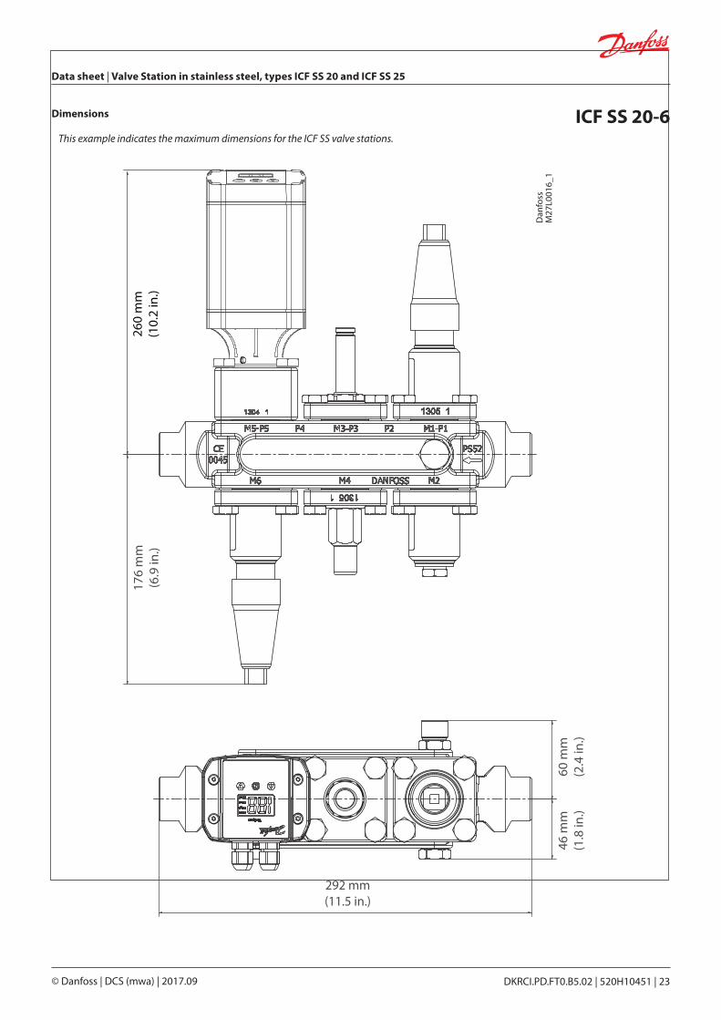
Dimensions ICF SS 20-6This example indicates the maximum dimensions for the ICF SS valve stations.
Dan
foss
M27
L001
6_1
260
mm
(10.
2 in
.)
Data sheet | Valve Station in stainless steel, types ICF SS 20 and ICF SS 25
DKRCI.PD.FT0.B5.02 | 520H10451 | 24© Danfoss | DCS (mwa) | 2017.09
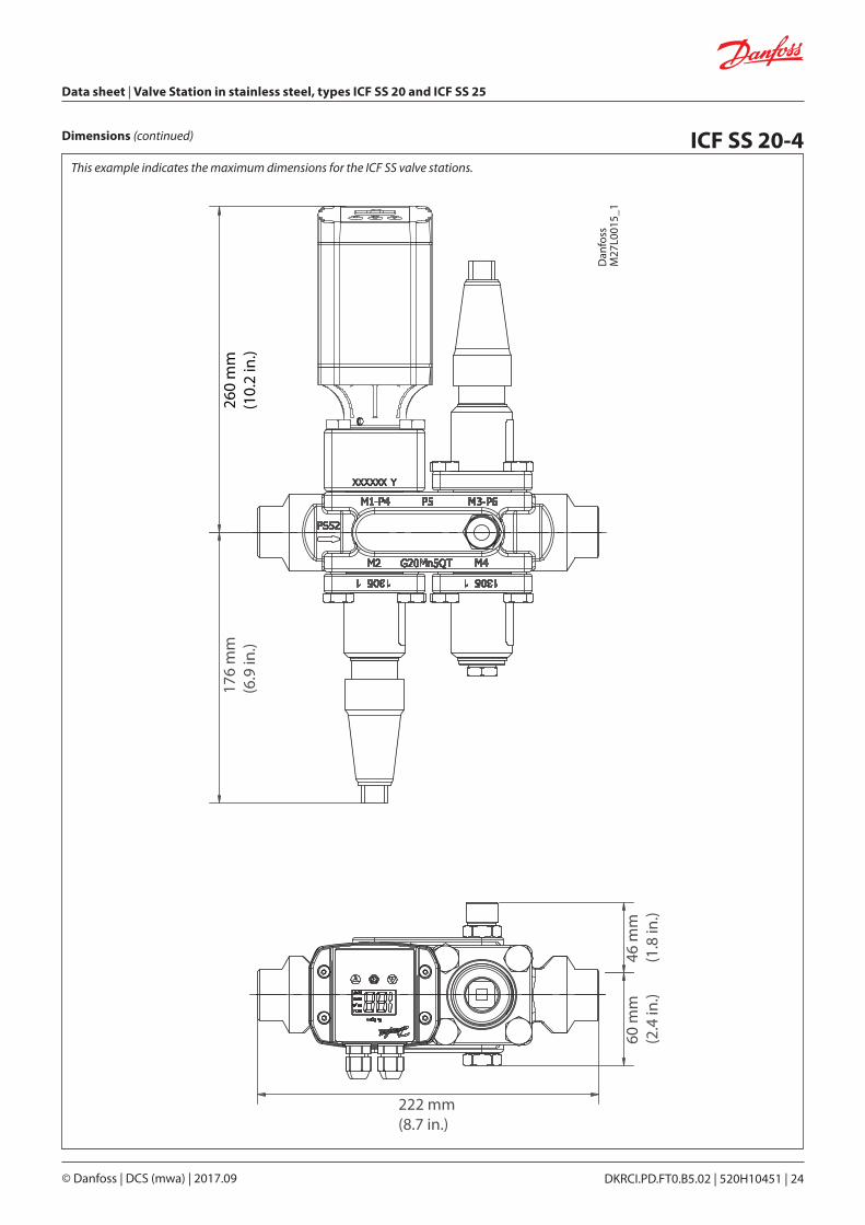
Dimensions (continued) ICF SS 20-4 This example indicates the maximum dimensions for the ICF SS valve stations.
Dan
foss
M27
L001
5_1
DKRCI.PD.FT0.B5.02 | 520H10451 | 25© Danfoss | DCS (mwa) | 2017.09
Data sheet | Valve Station in stainless steel, types ICF SS 20 and ICF SS 25
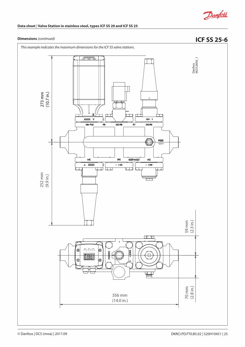
Dimensions (continued) ICF SS 25-625
2 m
m(9
.9 in
.)
59 m
m(2
.3 in
.)70
mm
(2.8
in.)
356 mm(14.0 in.)
Dan
foss
M27
L005
0_1
273
mm
(10.
7 in
.)This example indicates the maximum dimensions for the ICF SS valve stations.
Data sheet | Valve Station in stainless steel, types ICF SS 20 and ICF SS 25
DKRCI.PD.FT0.B5.02 | 520H10451 | 26© Danfoss | DCS (mwa) | 2017.09
Dimensions (continued) ICF SS 25-4
Dan
foss
M27
L005
1_1
252
mm
(9.9
in.)
58 m
m(2
.3 in
.)70
mm
(2.8
in.)
266 mm(10.5 in.)
273
mm
(10.
7 in
.)
This example indicates the maximum dimensions for the ICF SS valve stations.
DKRCI.PD.FT0.B5.02 | 520H10451 | 27© Danfoss | DCS (mwa) | 2017.09
Data sheet | Valve Station in stainless steel, types ICF SS 20 and ICF SS 25
DKRCI.PD.FT0.B5.02 | 520H10451 | 28© Danfoss | DCS (mwa) | 2017.09


![Section 18 Butterfly Valves - AAP Industries · BUTTERFLY VALVES [18] Wafer Butterfly Valve with Gear-Op Stainless Steel Wafer Butterfly Valve Wafer Butterfly Valve with Stainless](https://img.pdfslide.us/doc/110x75/60a1925cd0b68c353a5fc104/section-18-butterfly-valves-aap-industries-butterfly-valves-18-wafer-butterfly.jpg)