Embed Size (px)
Citation preview

G O R M A N - R U P P P U M P S
OF SELF-PRIMING CENTRIFUGAL PUMPS
SELECTION & APPLICATION
GRpumps.com
G O R M A N - R U P P P U M P S
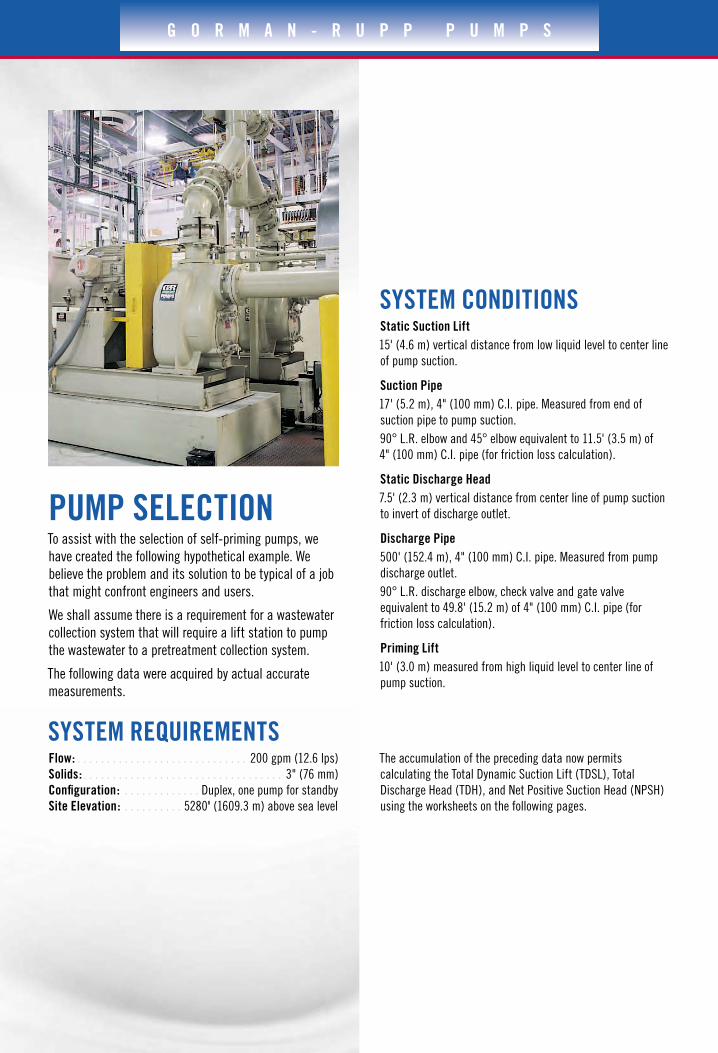
PUMP SELECTION To assist with the selection of self-priming pumps, we
have created the following hypothetical example. We
believe the problem and its solution to be typical of a job
that might confront engineers and users.
We shall assume there is a requirement for a wastewater
collection system that will require a lift station to pump
the wastewater to a pretreatment collection system.
The following data were acquired by actual accurate
measurements.
SYSTEM REQUIREMENTSFlow: . . . . . . . . . . . . . . . . . . . . . . . . . . . . . 200 gpm (12.6 lps)
Solids: . . . . . . . . . . . . . . . . . . . . . . . . . . . . . . . . . . 3" (76 mm)
Configuration: . . . . . . . . . . . . . Duplex, one pump for standby
Site Elevation: . . . . . . . . . . 5280' (1609.3 m) above sea level
SYSTEM CONDITIONSStatic Suction Lift
15' (4.6 m) vertical distance from low liquid level to center line
of pump suction.
Suction Pipe
17' (5.2 m), 4" (100 mm) C.I. pipe. Measured from end of
suction pipe to pump suction.
90° L.R. elbow and 45° elbow equivalent to 11.5' (3.5 m) of
4" (100 mm) C.I. pipe (for friction loss calculation).
Static Discharge Head
7.5' (2.3 m) vertical distance from center line of pump suction
to invert of discharge outlet.
Discharge Pipe
500' (152.4 m), 4" (100 mm) C.I. pipe. Measured from pump
discharge outlet.
90° L.R. discharge elbow, check valve and gate valve
equivalent to 49.8' (15.2 m) of 4" (100 mm) C.I. pipe (for
friction loss calculation).
Priming Lift
10' (3.0 m) measured from high liquid level to center line of
pump suction.
The accumulation of the preceding data now permits
calculating the Total Dynamic Suction Lift (TDSL), Total
Discharge Head (TDH), and Net Positive Suction Head (NPSH)
using the worksheets on the following pages.
S E L F - P R I M I N G P E R F O R M A N C E
CHOOSE FROM A FULL LINE OF SELF-PRIMING CENTRIFUGAL PUMPS
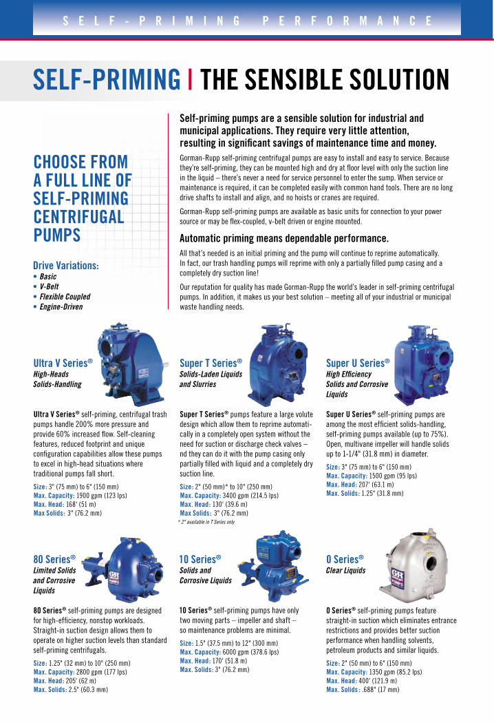
SELF-PRIMING | THE SENSIBLE SOLUTIONSelf-priming pumps are a sensible solution for industrial and municipal applications. They require very little attention, resulting in significant savings of maintenance time and money.
Gorman-Rupp self-priming centrifugal pumps are easy to install and easy to service. Because
they’re self-priming, they can be mounted high and dry at floor level with only the suction line
in the liquid – there’s never a need for service personnel to enter the sump. When service or
maintenance is required, it can be completed easily with common hand tools. There are no long
drive shafts to install and align, and no hoists or cranes are required.
Gorman-Rupp self-priming pumps are available as basic units for connection to your power
source or may be flex-coupled, v-belt driven or engine mounted.
Automatic priming means dependable performance.
All that’s needed is an initial priming and the pump will continue to reprime automatically.
In fact, our trash handling pumps will reprime with only a partially filled pump casing and a
completely dry suction line!
Our reputation for quality has made Gorman-Rupp the world’s leader in self-priming centrifugal
pumps. In addition, it makes us your best solution – meeting all of your industrial or municipal
waste handling needs.
Drive Variations: • Basic
• V-Belt
• Flexible Coupled
• Engine-Driven
80 Series®
Limited Solids
and Corrosive
Liquids
80 Series® self-priming pumps are designed
for high-efficiency, nonstop workloads.
Straight-in suction design allows them to
operate on higher suction levels than standard
self-priming centrifugals.
Size: 1.25" (32 mm) to 10" (250 mm)
Max. Capacity: 2800 gpm (177 lps)
Max. Head: 205' (62 m)
Max. Solids: 2.5" (60.3 mm)
10 Series®
Solids and
Corrosive Liquids
10 Series® self-priming pumps have only
two moving parts – impeller and shaft –
so maintenance problems are minimal.
Size: 1.5" (37.5 mm) to 12" (300 mm)
Max. Capacity: 6000 gpm (378.6 lps)
Max. Head: 170' (51.8 m)
Max. Solids: 3" (76.2 mm)
0 Series®
Clear Liquids
0 Series® self-priming pumps feature
straight-in suction which eliminates entrance
restrictions and provides better suction
performance when handling solvents,
petroleum products and similar liquids.
Size: 2" (50 mm) to 6" (150 mm)
Max. Capacity: 1350 gpm (85.2 lps)
Max. Head: 400' (121.9 m)
Max. Solids : .688" (17 mm)
Super U Series®
High Efficiency
Solids and Corrosive
Liquids
Super U Series® self-priming pumps are
among the most efficient solids-handling,
self-priming pumps available (up to 75%).
Open, multivane impeller will handle solids
up to 1-1/4" (31.8 mm) in diameter.
Size: 3" (75 mm) to 6" (150 mm)
Max. Capacity: 1500 gpm (95 lps)
Max. Head: 207' (63.1 m)
Max. Solids: 1.25" (31.8 mm)
Super T Series®
Solids-Laden Liquids
and Slurries
Super T Series® pumps feature a large volute
design which allow them to reprime automati-
cally in a completely open system without the
need for suction or discharge check valves –
nd they can do it with the pump casing only
partially filled with liquid and a completely dry
suction line.
Size: 2" (50 mm)* to 10" (250 mm)
Max. Capacity: 3400 gpm (214.5 lps)
Max. Head: 130' (39.6 m)
Max Solids: 3" (76.2 mm)* 2" available in T Series only
Ultra V Series®
High-Heads
Solids-Handling
Ultra V Series® self-priming, centrifugal trash
pumps handle 200% more pressure and
provide 60% increased flow. Self-cleaning
features, reduced footprint and unique
configuration capabilities allow these pumps
to excel in high-head situations where
traditional pumps fall short.
Size: 3" (75 mm) to 6" (150 mm)
Max. Capacity: 1900 gpm (123 lps)
Max. Head: 168' (51 m)
Max Solids: 3" (76.2 mm)

G O R M A N - R U P P P U M P S
HOW TO COMPUTE THETOTAL DYNAMIC HEAD (TDH)1
17.00'
2. Fittings in Equivalent Length of Pipe
a. One 90° L.R. Elbow, 4"–6.8' (100 mm–2.1 m) 11.50'
b. One 45° Elbow, 4"–4.7' (100 mm–1.4 m) (3.5 m)
3. Total Pipe (Actual & Equivalent) 28.50'
(8.7 m)
4. Total Friction Loss (.285' × 4.43' × .71') .90'
(.09 m × 1.4 m × .22 m) (.27 m) (based on friction coefficient C =100, 4.43/100' and correction factor
to C =120 = .71)
C. Total Dynamic Suction Lift 15.90'
(4.8 m)
TOTAL DISCHARGE HEAD: D + E = F
D. Static Discharge Head 7.50'
(2.3 m)
E. Friction, Discharge or Force Main Line
(Consult Hydraulic Handbook)
1. 500.00'
(152.4 m)
2. Fittings in Equivalent Length of Pipe
a. One 90° L.R. Elbow, 4"– 6.8' (100 mm–2.1 m)
b. One Check Valve, 4"–26' (100 mm–7.9 m)
c. One Plug Valve, 4"– 17' (100 mm–5.2 m) 49.80'
(15.2 m)
3. Total Pipe (Actual & Equivalent) 549.80'
(167.6 m)
4. Total Friction Loss (5.5' × 4.43' × .71') 17.30'
(1.7 m × 1.4 m × .22 m) (5.3 m) (based on friction coefficient C =100, 4.43/100' and correction factor to C =120 = .71)
F. Total Dynamic Discharge Head 24.80'
(7.5 m)
TOTAL DYNAMIC HEAD: C + F = TDH
C. Total Dynamic Suction Lift 15.90'
(4.8 m)
F. Total Dynamic Discharge Head +24.80'
(7.5 m)
Total Dynamic Head 40.70'
(12.4 m)
F
D
A CB1
E1
E2
B2
500' (152.4 m)
4" (100 mm) C.I. PIPE
6.8' (2.1 m) 26' (7.9 m) 17' (5.2 m)
49.8' (15.2 m)
10' (3.0 m)
5' (1.5 m)
2' (.6 m)
PUMP STARTS
PUMP STOPS
6.8' (2.1 m) 4.7' (1.4 m)
11.5' (3.5 m)
P
NOTE: Suction pipe must be
properly supported.
S E L E C T I N G T H E R I G H T P U M P
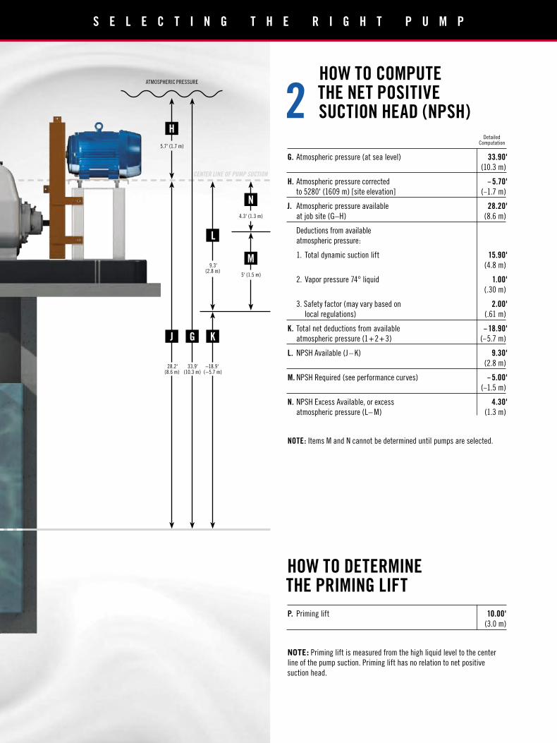
HOW TO COMPUTETHE NET POSITIVESUCTION HEAD (NPSH)2
HOW TO DETERMINETHE PRIMING LIFT
P. Priming lift 10.00'
(3.0 m)
NOTE: Priming lift is measured from the high liquid level to the center
line of the pump suction. Priming lift has no relation to net positive
suction head.
G. Atmospheric pressure (at sea level) 33.90'
(10.3 m)
H. Atmospheric pressure corrected – 5.70'
to 5280' (1609 m) [site elevation] (–1.7 m)
J. Atmospheric pressure available 28.20'
at job site (G–H) (8.6 m)
Deductions from available
atmospheric pressure:
1. Total dynamic suction lift 15.90'
(4.8 m)
2. Vapor pressure 74° liquid 1.00'
(.30 m)
3. Safety factor (may vary based on 2.00'
local regulations) (.61 m)
K. Total net deductions from available – 18.90'
atmospheric pressure (1+2+ 3) (–5.7 m)
L. NPSH Available (J – K) 9.30'
(2.8 m)
M. NPSH Required (see performance curves) – 5.00'
(–1.5 m)
N. NPSH Excess Available, or excess 4.30'
atmospheric pressure (L– M) (1.3 m)
NOTE: Items M and N cannot be determined until pumps are selected.
Detailed Computation
H
J G K
L
28.2'(8.6 m)
33.9'(10.3 m)
−18.9'(−5.7 m)
9.3'(2.8 m)
4.3' (1.3 m)
5.7' (1.7 m)
5' (1.5 m)
N
M
ATMOSPHERIC PRESSURE
CENTER LINE OF PUMP SUCTION
G O R M A N - R U P P P U M P S
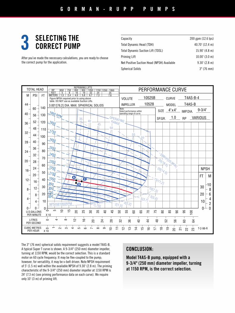
SELECTING THECORRECT PUMP3
After you’ve made the necessary calculations, you are ready to choose
the correct pump for the application.
The 3" (76 mm) spherical solids requirement suggests a model T4AS-B.
A typical Super T curve is shown. A 9-3/4" (250 mm) diameter impeller,
turning at 1150 RPM, would be the correct selection. This is a standard
motor on 60 cycle frequency. It may be flex-coupled to the pump;
however, for versatility, it may be v-belt driven. Note NPSH requirement
of 5' (1.5 m) well within the available NPSH of 9.30' (2.8 m). The priming
characteristic of the 9-3/4" (250 mm) diameter impeller at 1150 RPM is
24' (7.3 m) (see priming performance data on each curve). We require
only 10' (3 m) of priming lift.
CONCLUSION:
Model T4AS-B pump, equipped with a
9-3/4" (250 mm) diameter impeller, turning
at 1150 RPM, is the correct selection.
10528
T4AS-B-4
T4AS-B
4"x4" 9-3/4"
VARIOUS
REPRIMING LIFTSRP
FEETMETERS
6505
1,5
850164,9
7508
2,4
95019
5,8
1050226,7
1150247,3
Note:Select performance withinoperating range of curve.
1250 - 1950257,6
10525BFigure NPSH required prior to using abovetable. DO NOT use as available Suction Lifts.
3.00"/[76,2] DIA. MAX. SPHERICAL SOLIDS
T-2-98-R
1.0
140
130
120
110
100
90
80
70
60
50
40
30
20
10
0
60
56
52
48
44
40
36
32
28
24
20
16
12
8
4
0
44
40
36
32
28
24
20
16
12
8
4
0
0 4 8
12
16
20
24
28
32
36
40
44
48
52
56
60
64
0 5
10
15
20
25
30
35
40
45
50
55
60
65
70
75
80
85
90
95
100
X 10
0 1 2 3 4 5 6 7 8 9
10 11
12
13
14
15
16 17
18
19
20 21
22
23
X 10
NPSH
FT M
10
8
6
4
2
0
30
20
10
RP
LITRES
VOLUTE
IMPELLER
SIZE IMP.DIA.
PERFORMANCE CURVE
MODEL
CURVE
U.S.GALLONSPER MINUTE
SP.GR.
TOTAL HEAD
M PSI FT
PER SECOND
CUBIC METRESPER HOUR
1950 RPM
1850
1750
1650
1550
1450
1350
1250
1150
1050
950850750650
55
5045
4035
55
25[18,6]20[14,9]
15[11,2]
10[7,5]
7.5[5,6]5[3,7]2[1,5]1[,75]
28BHP[20,9KW]
3[2,2]
OPERATINGRANGE
NPSH@1950RPM
A
B
C
0
Capacity 200 gpm (12.6 lps)
Total Dynamic Head (TDH) 40.70' (12.4 m)
Total Dynamic Suction Lift (TDSL) 15.90' (4.8 m)
Priming Lift 10.00' (3.0 m)
Net Positive Suction Head (NPSH) Available 9.30' (2.8 m)
Spherical Solids 3" (76 mm)

SELECTING THE
CORRECT MOTOR4Calculating the correct motor size for a pump involves the use of a
complicated formula. To make this process easier, many manufacturers
add horsepower (or kilowatt) lines to their performance curves. Referring
to point on the curve, the closest non-overloading horsepower line
represents 5 brake horsepower (BHP) or 3.7kW.
A good rule of thumb to use when selecting motors is to apply a motor
which will provide sufficient power to cover the entire length of the
selected pump curve (a practice which results in a “non-overloading”
motor selection). Using our example, the selected operating speed of the
pump is 1150 RPM. The performance of a pump will follow along this
speed curve but will vary due to normal pump wear and changes in sump
level. The calculation below accounts for the sump level change between
the pump on and off levels.
TDH AT THIS LEVEL 35.70' (10.9 m)
40.70' (12.4 m)
–5.00' (–1.5 m)
35.70' (10.9 m)
or: 36' (11.0 m) TDH at point on curve.
TDH AT THIS LEVEL 40.70' (12.4 m)
See on curve.
The change shown above is basically a change in static head. The actual
performance of the pump is illustrated on the curve where the 1150 RPM
curve and hydraulic system curve intersects (this is noted on the curve as
point ). The difference in flow rate between points and is the
band our selected pump will operate within from the beginning to the end
of the pumping cycle.
Taking all this information into consideration, the best course of action
is to select a 7½ HP (5.6kW) motor to ensure non-overloading operation
throughout the pump’s operating range.
2'
5'
PUMP STARTS
PUMP STOPS
S E L E C T I N G T H E R I G H T P U M P
NOTE: Suction pipe must be
properly supported.
Printed in the USA
Gorman-Rupp InternationalP.O. Box 1217Mansfield, Ohio 44901-1217, USATel: 419-755-1011Fax: 419-755-1266E-mail: [email protected]
The Gorman-Rupp CompanyMansfield DivisionP.O. Box 1217Mansfield, Ohio 44901-1217, USATel: 419-755-1011Fax: 419-755-1251E-mail: [email protected]
GRpumps.com©2009-2012 The Gorman-Rupp Company. All rights reserved.
Gorman-Rupp of Canada, Ltd.70 Burwell RoadSt. Thomas, Ontario N5P 3R7, CanadaTel: 519-631-2870Fax: 519-631-4624E-mail: [email protected]
Product information is subject to change; consult factory for details.
ISO 14001
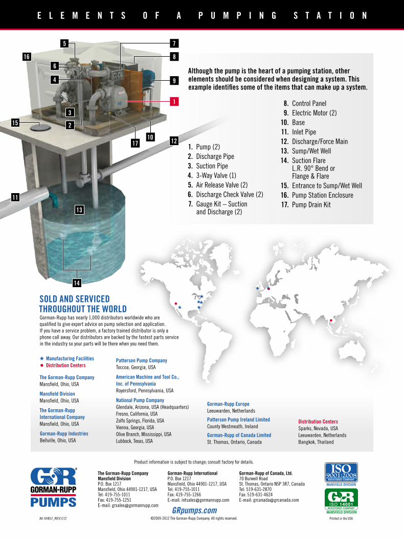
E L E M E N T S O F A P U M P I N G S T A T I O N
1. Pump (2)
2. Discharge Pipe
3. Suction Pipe
4. 3-Way Valve (1)
5. Air Release Valve (2)
6. Discharge Check Valve (2)
7. Gauge Kit – Suction and Discharge (2)
Although the pump is the heart of a pumping station, other elements should be considered when designing a system. This example identifies some of the items that can make up a system.
8. Control Panel
9. Electric Motor (2)
10. Base
11. Inlet Pipe
12. Discharge/Force Main
13. Sump/Wet Well
14. Suction Flare L.R. 90° Bend or Flange & Flare
15. Entrance to Sump/Wet Well
16. Pump Station Enclosure
17. Pump Drain Kit
16
13
11
121710
14
8
9
75
6
4
3
2
1
15
AV-04857_REV1112
SOLD AND SERVICED THROUGHOUT THE WORLDGorman-Rupp has nearly 1,000 distributors worldwide who are
qualified to give expert advice on pump selection and application.
If you have a service problem, a factory trained distributor is only a
phone call away. Our distributors are backed by the fastest parts service
in the industry so your parts will be there when you need them.
Manufacturing Facilities
Distribution Centers
The Gorman-Rupp Company
Mansfield, Ohio, USA
Mansfield Division
Mansfield, Ohio, USA
The Gorman-Rupp
International Company
Mansfield, Ohio, USA
Gorman-Rupp Industries
Bellville, Ohio, USA
Patterson Pump Company
Toccoa, Georgia, USA
National Pump Company
Glendale, Arizona, USA (Headquarters)
Fresno, California, USA
Zolfo Springs, Florida, USA
Vienna, Georgia, USA
Olive Branch, Mississippi, USA
Lubbock, Texas, USA
American Machine and Tool Co.,
Inc. of Pennsylvania
Royersford, Pennsylvania, USA
Distribution Centers
Sparks, Nevada, USA
Leeuwarden, Netherlands
Bangkok, Thailand
Patterson Pump Ireland Limited
County Westmeath, Ireland
Gorman-Rupp Europe
Leeuwarden, Netherlands
Gorman-Rupp of Canada Limited
St. Thomas, Ontario, Canada