Embed Size (px)
Citation preview

PFR STUDIES OF SELA URTHING HE PROJECT
SELA URTHING
H.E. PROJECT (230 MW)
CONTENTS
CHAPTERS
NAME
Page No.
Salient Features i-iii
I Executive Summary 1-1 to 1-5
II Background Information 2-1 to 2-5
III The Project Area 3-1 to 3-5
IV Topography and Geotechnical Aspects 4-1 to 4-5
V Hydrology 5-1 to 5-17
VI Conceptual Layout and Planning 6-1 to 6-14
VII Power Potential Studies 7-1 to 7-8
VIII Power Evacuation 8-1 to 8-2
IX Initial Environment Examination Studies 9-1 to 9-24
X Infrastructure Facilities 10-1 to 10-4
XI Construction Planning & Schedule 11-1 to 11-7
XII Cost Estimate 12-1 to 12-3
XIII Economic Evaluation
13-1 to 13-3
APPENDICES
1.1 Observation of CWC on Hydrological
studies
1.2 Replies to observations of hydrological
studies
2.0 Drawings

PFR STUDIES OF SELA URTHING HE PROJECT

PFR STUDIES OF SELA URTHING HE PROJECT
ii
LIST OF DRAWINGS
SELA URTHING H.E. PROJECT
S. NO. DESCRIPTION DRAWING NO.
1. Vicinity Map
-
2. General Layout Plan of Sela Urthing WAP/PFR/SELA URTHING/1001
3. L-Section Profile along Water Conductor System
WAP/PFR/ SELA URTHING /1002
4. Upstream Elevation and Top Plan of Dam WAP/PFR/ SELA URTHING / 1003
5. Sections of non-overflow and overflow blocks of dam
WAP/PFR/ SELA URTHING /1004
6. Power Intake Plan & Section WAP/PFR/ SELA URTHING /1005
7. Head Race Tunnel Typical Sectional Detail
WAP/PFR/ SELA URTHING /1006
8. Power House Plan
WAP/PFR/ SELA URTHING /1007
9. Power House Cross Section
WAP/PFR/ SELA URTHING /1008
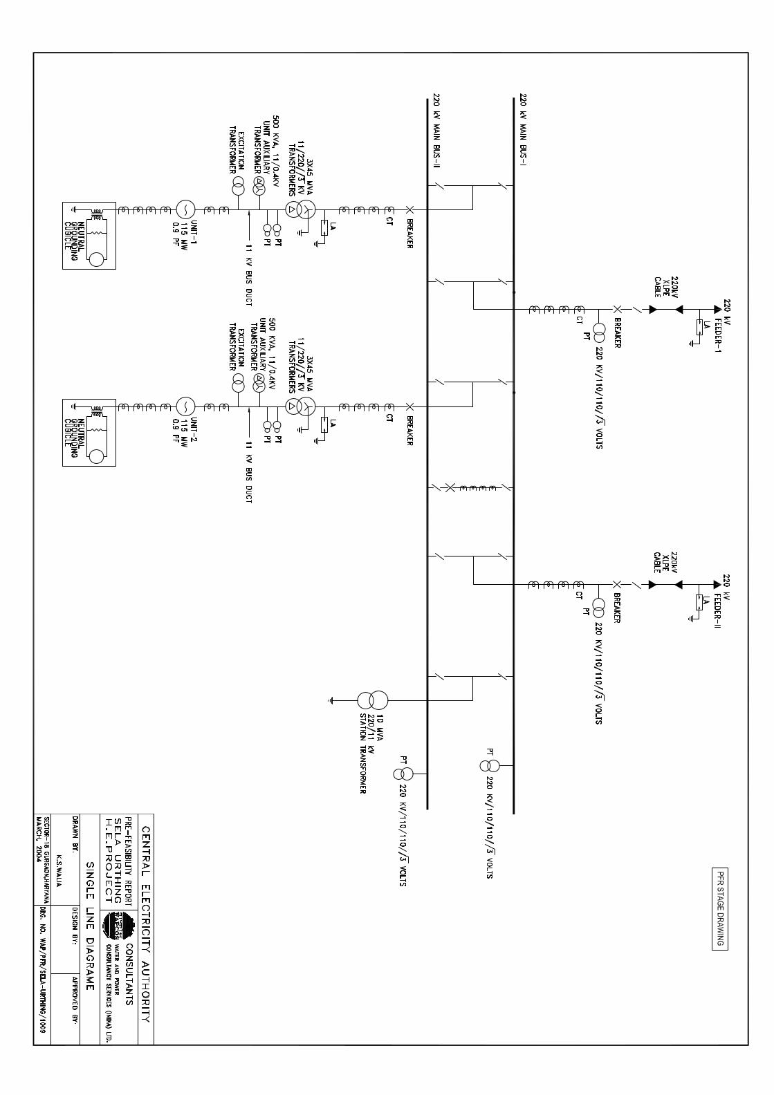
10 Single Line Diagram WAP/PFR/ SELA URTHING/1009

PFR STUDIES OF SELA URTHING HE PROJECT
FOREWORD
The economic growth is solely dependent on the level of Infrastructural Development and
electrical energy forms a very important input to the development process. Hydro power
development is inexhaustible and most eco friendly development of energy resources. Hydro
power development in last 100 years could be achieved to about 25% of the total power
generation which is about 32% only of the total hydro potential of the country. Looking to the
future demand of energy matching with the economic growth, it is imperative to harness the
balance hydro power potential in planned manner. Hon’ble Prime Minister of India
Sh. A.B. Vajpayee has taken a gigantic step by launching 50,000 MW Hydro Power Initiative
during May, 2003 to accomplish the target by the XI th five year plan onwards.
WAPCOS feels honoured to be associated with this Hydro Power Initiative and the follow up
under taken by the Minister of Power and CEA, Govt. of India and have entrusted with the
responsibility of preparation of 71 Nos. of Prefeasibility stage reports. The entire work is
being carried out by our in-house expertise. The studies have been carried out in close
association with CEA, CWC, GSI, SOI, IMD and State Departments incorporating their
suggestions / comments in finalizing the respective PFR studies. WAPCOS presents the
PFR stage report of Sela Urthing H.E. Project which has an installed capacity of
230(2X115 MW).
WAPCOS is grateful to Central Electricity Authority and Ministry of Power, GOI for providing
this opportunity and to be associated with the Hydro Power Initiative and we assure for our
best efforts and acknowledge with thanks the various departments for extending co-
operation to WAPCOS in completing the task in a scheduled manner.
New Delhi (D. DATTA) March, 2004 Chairman & Managing Director

PFR STUDIES OF SELA URTHING HE PROJECT
i
SELA URTHING H.E. PROJECT
SALIENT FEATURES
LOCATION
State Uttaranchal District Pithoragarh River Dhauliganga (Sarda basin)
Dam site 450 m D/s of confluence of Sela Yankti with Dhauliganga River
Nearest Airport Delhi Nearest rail head Tanakpur Location of Dam Site Latitude 30o 08’ 29” N Longitude 80o 36’ 23” E
HYDROLOGY
Catchment area at dam site 921 sq km Maximum average Discharge at dam site 64.84 cumec Minimum average Discharge at dam site 42.77 cumec RESERVOIR
Full reservoir level (FRL) 2470
Minimum drawdown level (MDDL) 2455 Gross storage at FRL 3.06 M cum Live storage 1.705 M cum
Area under Submergence at FRL 15.723 ha
DIVERSION TUNNEL
Number 1 Size 7.5 m D-shaped Length 300 m Diversion discharge 255.32 cumec
DAM Type Concrete Gravity Dam
Top elevation of dam 2473 m Height of dam above 73 m
PFR STUDIES OF SELA URTHING HE PROJECT
ii
deepest foundation level Length of dam at top 185 m River bed level 2415 m SPILLWAY Design flood 4603.03 cumec Type Sluice spillway Crest elevation 2440 m Number 4 Length of spillway 56 m Energy dissipation type Stilling basin INTAKE Invert level 2440.9 Number 2 Size of gate opening 4m x 4m Trash rack 5m x 14.1m x 8 no.
DESILTING CHAMBER
Number 2 Size 12.50m (W) x 18m(H) Length 220 m Design discharge 62.59 Particle size to be removed 0.2 mm and above HEAD RACE TUNNEL
Number 1 Size 5.5 m dia Shape Horse shoe Length 2.01 km SURGE SHAFT
Number 1 Size 10 m dia Height 70.4 m PENSTOCK
Numbers 1 bifurcating to 2 nos. Size 4.8 m dia bifurcated & reduced to 3.4 m Length 410 m

PFR STUDIES OF SELA URTHING HE PROJECT
iii
POWER HOUSE
Type Surface Installed capacity 230 MW Number of units 2 Power house size 20 m x 69 m Type of turbine Vertical Francis C.L. of turbine 2194 m Rated Head 255.5 m TAIL RACE Size 12.75 m – bed width Type Open channel Length 30 m Design Discharge 100.14cumec River Bed Level 2198.0 Normal TWL 2203 m SWITCHYARD Size 200 m x 150 m
POWER GENERATION
Installed capacity 230 MW Annual energy generation i) 90% dependable year 816.73 GWh ii) Energy in 90% year on 95% availability 803.42 GWh COST ESTIMATES & FINANCIAL ASPECT (Rs. Crores) Civil Works 356.80 Electro Mechanical Works 213.72 Sub Total 570.60 Interest during construction 92.38 Total (Generation) 662.98 Transmission works 33.75 Grand Total 696.73 Tariff for first year Rs. 1.40/KWh Levellised Tariff Rs. 1.22/KWh CONSTRUCTION PERIOD 5 years and 6 months

PFR STUDIES OF SELA URTHING HE PROJECT
13-1
CHAPTER – I
EXECUTIVE SUMMARY
1.1 INTRODUCTION
The Sela Urthing Hydroelectric Project located in Pithoragarh district of
Uttaranchal envisages utilization of the waters of the river Dhauliganga, a
tributary of Kali (Sarda), for power generation on a run of river type
development, harnessing a head of about 270 m.
The project with a proposed installation of 230 MW (2x115 MW) would afford
an annual energy generation of 826.08 GWh in a 90% dependable year. The
tariff from the project at present day cost would be Rs. 1.36/KWh (levellised).
The diversion site is located at Latitude 30o 08’ 29” N; Longitude 80o 36’
23” E. The dam site is approachable from Tanakpur by road at a distance of
263 km upto Khela and 20 kms from Khela by Kuchha Road . The nearest rail
head is located at Tanakpur and nearest airport is located at Delhi.
1.2 SCOPE OF WORKS
The Sela Urthing HE project envisages construction of:
• a 73 m high Concrete Gravity diversion dam across river Dhauliganga
to provide a live storage of 1.71 M cum with FRL at 2470 m and MDDL
at 2455 m;
• two nos. desilting chambers of length 284 m (L) and size 13m (W)x 16
m (H) to remove silt particles of size 0.2 mm and above;
PFR STUDIES OF SELA URTHING HE PROJECT
13-2
• a 2.01 km long and 6.0 m dia head race tunnel terminating in a surge
shaft
• a 70.4 m high 10 m dia surge shaft
• 410 m long, 4.6 m dia penstock
• a surface power house having an installation of 2 Francis driven
generating units of 115 MW each operating under a rated head of
259.55 m; and
• 30 m long open tail race channel to carry the power house releases
back to the river
The power generated from the project would be evacuated through 400 kV
DC lines to a pooling station near Bareilly to feed power to the power grid.
The Salient features of the project are given at Annex-I and a layout map at
Plate-I.
1.3 HYDROLOGY
The river Dhauliganga drains a catchment area of about 921 sq. km at the
proposed dam site. The water availability for the project has been considered
on the basis of 10 daily discharge series at Pancheswar dam site for the
period 1962-92. The flow series for Sela Urthing HE Project were derived by
carrying out runoff-runoff correlation between concurrent flows at Chirkila &
Pancheswar and subsequent reduction in proportion to the catchment area.
The computed inflow series worked out has been utilized for Power Potential
Studies. The design flood has been assessed as 4603.03 cumec.

PFR STUDIES OF SELA URTHING HE PROJECT
13-3
1.4 POWER POTENTIAL STUDIES
The computed inflow series for 30 years viz 1962-63 to 1991-92 has been
considered in the assessment of power benefits from the project. As per GOI
notification for tariff the year 1976-77 corresponds to 90% dependable year.
An installation of 230 MW comprising of 2 generating units of 115 MW has
been proposed. The energy availability from the project in a 90% dependable
year has been summarized below:
Particulars 90% 90% Dependable Year Dependable Year
Annual Energy Generation
Annual Energy Generation (GWh): 826.08
Annual Load Factor (%) : 41.0
Generation during Lean Flow Season (Dec.-Feb.)
Energy Output (MWc) 38.31
Load Factor (%) 16.66
The design energy for tariff at 95% availability in a 90% dependable year has
been worked out at 811.0 GWh.
A live storage of 1.71 M cum has been provided in the diversion dam which
would enable the station to operate as peaking station. The pondage is
equivalent to 1104.26 MWh which is sufficient to operate the station for 4.80
hours.

PFR STUDIES OF SELA URTHING HE PROJECT
13-4
1.5 POWER EVACUATION ASPECTS
The power of this project is intended to be evacuated by proposed 400 kV
D/C lines to newly proposed 400 kV substation by PGCIL at Bareilly which is
a load centre. The line is originating from Bokang Baling HEP with LILO at
Sela Urthing HEP.
1.6 ENVIRONMENTAL ASPECTS
The project is located in the remote area of Dhauliganga valley. The total land
requirement for the construction of various components is 65 ha. Private land
is 4.0 ha. Most of the land falls under the category of forest land. Based on
assessment of environmental impacts, management plans have to be
formulated for Catchment Area Treatment, compensatory afforestation and
other environmental issues. These issues would be addressed during the
investigation for DPR.
1.7 ESTIMATES OF THE COST
The project is estimated to cost Rs. 745.82 Crores including IDC at June,
2003 price levels. The preliminary cost estimate of the project has been
prepared as per guidelines of CEA / CWC. The break down of the cost
estimates is given below:
Civil Works : Rs. --Crores
Electro Mechanical Works : Rs. 241.95 Crores
Sub total : Rs. 643.99 Crores
Interest During construction : Rs. 101.83 Crores
Total (Generation) : Rs. 745.82 Crores
Transmission works : Rs. 27.50 Crores
Grand Total : Rs. 773.32 Crores

PFR STUDIES OF SELA URTHING HE PROJECT
13-5
1.8 FINANCIAL ASPECTS
As indicated above, the Sela Urthing HE project, with an estimated cost
(Generation only) of Rs. 745.82 Crores (including IDC of Rs. 101.83 Crores)
and design energy of 811.0 GWh in a 90% dependable year is proposed to
be completed in a period of 5 years and 6 months. The tariff has been
worked out considering a debt-equity ratio of 70:30, 16% return on equity,
annual interest rate on loan at 10%. The tariff for first year and levellised tariff
(at power house bus bar) have been worked out as Rs. 1.56/ kWh &
Rs. 1.36/kWh respectively.
1.9 CONCLUSIONS
Sela Urthing HE project involves simple civil works and could be completed in
5 years and 6 months. The project would afford a design energy of 811.0
GWh in a 90% dependable year. The cost per MW installed works out as Rs.
2.8 Crores. The Preliminary Feasibility Report indicates that the scheme
merits consideration for taking up for Survey & Investigation and preparation
of DPR.

PFR STUDIES OF SELA URTHING HE PROJECT
2-1
CHAPTER - II
BACKGROUND INFORMATION
2.1 GENERAL In Nov.2000, Uttaranchal State was carved out of thirteen hill districts of
Northern U.P. The state borders with Nepal and Tibet on the east, Central
Himalayas on the north, Haryana and Himachal Pradesh on the west and
northwest respectively.
Geophysically the state has four Mountain Zones namely Foot hills, Lesser
Himalayas, Greater Himalayas and Trans-Himalayas. The mountains are
covered with perpetual snow and glaciers and has gifted the north India a
perennial river system of the Ganga and its tributaries. The tributaries of
Ganga, namely Alaknanda, Bhagirathi, Yamuna and Sarda originate from
the foothills of snow capped peaks and glaciers in the Central Himalayas and
incise their respective courses through the rugged terrain, splash and surge
the steep gradients and most of the streams offer excellent potential for
Hydro power development.
The region is blessed with magnificent glaciers, majestic rivers, gigantic snow
capped peaks, Valley of flowers natural beauty and rich flora and fauna.
Many holy shrines have blessed the state spiritually and given the name of
Dev Bhoomi or Land of Gods. The seasonal influx of tourists, the seekers of
peace for visit to the holy shrines and lovers of nature contribute to the state
income.
The state is divided into Kumaon and Garhwal Divisions with 13 districts,
42 tehsils, 95 blocks, and 15689 inhabited villages and 73 towns. The
State has a geographical area of 53, 119 sq. km which is 1.62% of the total
area of the country and supports 84.8 lakh population which is 0.83% of

PFR STUDIES OF SELA URTHING HE PROJECT
2-2
the total population of India. The percentage of villages having population
more than 500 is about 11.4% (1991 Census). The existing majority of
smaller settlements of Uttaranchal pose a serious challenge for economic
infrastructure and lack of services to the far flung places in the hilly terrain
makes Uttaranchal as one of the extremely backward states of India.
It has 76.1% electrified villages as compared to 75.3% of villages of U.P.
The average per capita consumption of electricity is 245.57 kWh whereas
Dehradun and Nainital consume 480.81 and 447.33 kWh respectively
with a minimum consumption of 43.7 kwh in Uttarkashi.
2.2 POWER SCENARIO IN NORTHERN REGION
2.2.1 Present Status
Most of the states in the Northern Region have been experiencing energy
shortage as well as shortage of Peak Power of varying degree. Actual Power
supply position in the Northern Region during the year 2001-2002 has been
as under:
Energy (in MU), year 2001-2002
State Require-ment
Availability Shortage(-)/ Surplus (+)
%age
Chandigarh 1110 1108 (-) 2 0.2
Delhi 19350 18741 (-)609 3.1
Haryana 18138 17839 (-)299 1.6
Himachal Pradesh 3293 3206 (+) 87 2.6
Jammu & Kashmir 6635 5899 (-) 736 11.1
Punjab 28780 27577 (-)1203 4.2
Rajasthan 24745 24495 (-)250 1.0
Uttaranchal-U.P 48332 43545 (-)4787 9.9
Northern Region 150383 142410 (-)7973 5.3

PFR STUDIES OF SELA URTHING HE PROJECT
2-3
2.2.2 Peak Power (in MW), year 2001-2002
State Peak Demand
Peak Met Shortage(-)/ Surplus (+)
%age
Chandigarh 180 180 0 0.0
Delhi 3118 2879 (-)239 7.7
Haryana 3000 2900 (-)100 1.6
Himachal Pradesh 562 562 0 0.0
Jammu & Kashmir 1209 999 (-) 210 17.4
Punjab 5420 4936 (-)484 8.9
Rajasthan 3700 3657 (-)43 1.2
Uttaranchal-U.P 7584 6887 (-)607 9.2
Northern Region 24773 23000 (-)1773 7.2
2.3 NECESSITY OF HYDRO POWER DEVELOPMENT IN UTTARANCHAL 2.3.1 Hydro and Thermal Power Mix
The main resources for generating electricity are by utilising the hydro
potential available along the river drops besides the use of fossil fuel.
Presently the ratio of thermal generation and Hydro-electric generation in
Uttaranchal Power grid, is quite disproportionate. With the diminishing coal
resources and difficult oil position all over the world, it is necessary that
electric generation be aimed to achieve the economic balance of 40:60
between the hydro and thermal generation of power, as against the existing
25:75 ratio.
2.4 BRIDGING THE GAP OF HYDRO POWER GENERATION
The requirement of power in Uttranchal is very fluctuating because of many
seasonal and other similar demands of industries. To improve the share of

PFR STUDIES OF SELA URTHING HE PROJECT
2-4
hydro-power generation it is essential to develop the hydroelectric power
potential of state which is about 15110 MW, of which so far only 8% has been
developed.
The existing installed generating capacity in the State is about 1286
MW ( 2003 fig) and the entire capacity is from hydro generation. There is no
thermal power generation in the state . The major hydro power stations
under construction in the state are (i) Maneri Bhali, Stage-II (304 MW), (ii)
Lakhawar Vyasi, Stage-I (300 MW), (iii) Lakhwari Vyasi, Stage-II (120
MW), (iv) Srinagar H.E. Project (330 MW), (v) Vishnuprayag Scheme (400
MW), (vi) Tehri Dam Project, Stage-I (1000 MW), (vii) Tehri Dam Project,
Stage-II (1000 MW), (viii) Koteshwar Dam Project (400 MW), and (ix)
Dhauliganga H.E. Project, Stage-I (280 MW).
With the rising hydro power generation and improving efficiencies in
distribution of electricity, Uttaranchal hopes to offer energy at stable prices
for eco-friendly industrial development. Though the state is more or less
sufficient in its energy generation to meet its own requirement, there is an
urgent need to develop its huge untapped hydro power potential in an early
and efficient manner, manage efficiently the hydro generation capacity of
existing power stations and to develop and promote new Hydro projects
with the purpose of harnessing hydropower resources in the state for
economic well being and growth of the people in the whole region.
In order to meet the load demand satisfactorily, it is considered essential to
maintain a minimum gross margin of about 30 per cent over the projected
peak demand while planning for expansion of power supply facilities.
To bridge the gap between the demand for power and the availability of
power, some of the major hydro-electric schemes identified in Ganga Valley
for development are indicated below :
PFR STUDIES OF SELA URTHING HE PROJECT
2-5
i Tapovan Vishnugad (360
MW)
viii Karanprayag Dam (252 MW)
ii Bowala Nandprayag (132
MW)
ix Lata Tapovan (108 MW)
iii Kishau Dam (600 MW) x Vishnugad Pipalkoti (340 MW)
iv Pala Maneri (416 MW) xi Pancheshwar Dam
v Loharinag Pala (520 MW) xii Chamgad Dam (400 MW)
vi Koth Bhel (1000 MW) xiii Dhauliganga, Stage-II
vii Utyasu Dam (1000 MW)
2.5 PRESENT STUDIES 2.5.1 With a view to prioritize the large number of identified schemes to harness
vast untapped hydro resources in the order of their attractiveness for
implementation, “Ranking studies” were carried out by CEA. Subsequently,
after consultation process initiated by Ministry of Power with various state
agencies, CPSUs etc., it was considered appropriate that Preliminary
Feasibility Report (PFRs) of selected hydroelectric projects be taken up so
that feasibility of the schemes considered in ranking studies could be
established.
2.5.2 In order to achieve the above objective the present preliminary feasibility
stage report presents the Sela Urthing H.E. Project located in Pithoragarh
District, as detailed in the subsequent Chapters.
2.5.3 In view of the power scenario described above, the envisaged Sela Urthing
H.E. Project with an installed capacity of 230 MW will help in a long way in
meeting the projected power demand.

PFR STUDIES OF SELA URTHING HE PROJECT
3-1
CHAPTER-III
PROJECT AREA
3.0 DHAULIGANGA RIVER BASIN 3.1 Dhauliganga river is the northernmost right bank tributary of river Kali and lies
entirely in the Pithoragarh district of Uttranchal state of India. The
Dhauliganga basin is bounded between latitude 290 55' - 30 0 35' N and
longitude 800 15' - 80 0 45' E. This is a glacial and snowfed river and
originates in the Lesser Himalayas from snow peaks at an elevation of 5,160
m and flows down as a small stream in a narrow valley, generally in
NE –SE direction over a length of 85 km before joining the Kali river at an
elevation of approximate 1100.0 m. The average bed slope of the
Dhauliganga river is approximately 1 in 20 and can be termed as a fast
flowing ferocious river. The river valley is located in high mountain ranges on
both banks over most of its stretch. The river brings down a considerable
amount of sediment load particularly during snow-melt and flood season.
3.2 PROPOSED BASIN DEVELOPMENT 3.2.1 Currently under Execution
The available drop of about 2000 m from Bokang to the confluence of
Dhauliganga with Kali river was noticed and was under study by the UP
Irrigation Department since 1970 for utilsiation of its hydroelectric potential. A
proposal utilizing the combined flows of Dhauliganga and Goriganga was
considered to generate 900 MW through an underground power stations and
later shelved on geotechnical considerations. Subsequently the development
of 2000 m drop in Dhauliganga was instead envisaged in a cascade
development comprising 6 stages and some preliminary studies were done by
UP Government for Dhauliganga Relagad scheme, now called Dhauliganga

PFR STUDIES OF SELA URTHING HE PROJECT
3-2
Stage I by NHPC. This scheme is under execution by NHPC with a diversion
dam near Chirkila village having an FRL at EL 1345.0 m. The following are
the main details of this project:
1 Reservoir level EL 1345.0 m
2 TWL EL 1034.1 m
3 Gross storage 6.2 M Cum
4 Dam height 56.0 m
5 Type of dam Rock fill
6 River bed level EL 1301.0 m
Installed capacity 4 x 65 MW
Energy Generation
(a) in 90% dependable year
(b) in 50% dependable year
1,187 Gwh
1, 354 Gwh
3.2.2 Future Development
The toposheets prepared by survey of India reveal that there is tremendous
scope of harnessing the hydro power potential available in upstream of
Dhauliganga Stage I HE project, under execution by NHPC, Central
Electricity Authority on their preliminary assessment in the Ranking studies
have identified the following projects with the FRLs & TWLs proposed by them
and as per WAPCOS investigation and studies:

PFR STUDIES OF SELA URTHING HE PROJECT
3-3
S. No.
Name of Scheme As per CEA As per WAPCOS investigation
FRL (m)
TWL (m)
FRL (m)
TWL (m)
1 Bokang Bailing 3200 2840 3280 2780
2 Chhunger Chal 2800 2480 2780 2470
3 Sela Urthing 2480 2200 2470 2200
4 Urthing – Sobala 2200 1620 N.A. N.A.
5 Sobala-Jhumrigaon 1620 1480 Dropped because of
Dhauliganga Stage II.
6 Dhauliganga Stage-
II
1597.0 1330.0
CEA has awarded the preparation of pre-feasibility Reports for schemes at Sl.
No. 1 to 5. Sobala – Jhumrigaon (Sl. No. 5) has been dropped in
consultation with CEA because of the proposed Dhauliganga Stage II
downstream.
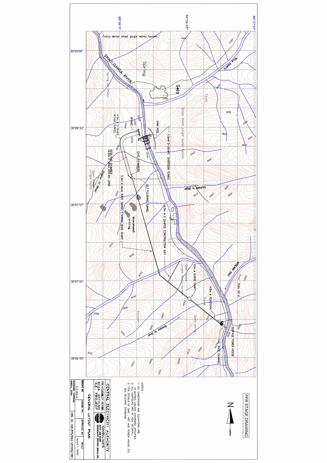
3.3 DESCRIPTION OF SELA URTHING H.E. PROJECT
Sela Urthing H.E. Project upstream of the proposed Urthing Sobala H.E.
Project will harness the hydro-power potential of the river between EL 2470 m
and EL 2200 m.
The project envisages the construction of a concrete gravity dam with
overflow spillway just downstream of Sela village with FRL at +2470.0 m.
This spillway is designed to pass a maximum flood of 4603.03 cumecs. Two
intakes having total capacity of 125.181 m3/s, are proposed on the right bank
of river. The trash rack of the intake after 50% clogging is designed to restrict
the inflow at a maximum velocity of 0.75 m/s. The inflow through the intake is
controlled by an intake gate of size 4 m x 4 m. The inflow into each intake

PFR STUDIES OF SELA URTHING HE PROJECT
3-4
is collected by individual intake tunnel of 4.0 m dia and is led to respective
desilting chamber which is designed to flush out all silt particles of 0.20 mm
size and above. A control gate shaft is proposed at the end of the desilting
chamber for purposes of desilting the chamber, when required. The desilting
chamber is provided with silt flushing gate, so that silt laden water can be
flushed out to a silt flushing tunnel (steel lined to withstand erosion) which
brings the silt laden waters back to the river downstream of diversion
structure.
The silt-free waters from the desilting chamber is led to a 2.01 km long 5.5 m
dia horse-shoe shaped Head Race tunnel. Since the length of water
conductor is more than 5 times the head, a surge shaft is proposed in this
scheme and the flow is then fed into a penstock of 4.8 m dia (steel lined)
which bifurcates into 3.4m each near the surface power house to feed 2 x
115 MW Francis turbines.
The surface power house will have two vertical francis turbines of 115 MW
capacity which will generate 816.73 Gwh m a 90% dependable year.
The draft tubes will lead the discharge back to river through a tailpool and a
small tailrace channel with minimum tail water level of 2200.0 m. The
detailed description of the project features are given in Chapter-VI.
3.4 SOCIO ECONOMIC PROFILE
The entire region has undulating topography with lofty mountains jutting out
that create a rugged terrain with steep valleys. The geology, soil texture and
climate are highly variable including the habitation pattern. It has sparse and
scanty population, small sized villages, scattered on the hilly landscape. Out
migration of able bodied persons is common. Subsistence level agriculture
based economy mostly prevails with marginal holdings. The infrastructural
development becomes very costly in such terrain.

PFR STUDIES OF SELA URTHING HE PROJECT
3-5
Pithoragarh District has an area of 17.3% and supports 9.55% population as
compared to the state. The density of population is about 64 persons per
sq.km as against 116 persons per sq.km of the state. The literacy rate both
among males and females is lowest in the district standing at 59.0% and
38.37% as against the state average of 59.6% and 42.9% respectively. The
population of schedule castes is about 20.45% against state average of
16.7%.
The main work force, about 75%, is engaged in primary and secondary
sectors and the balance in allied sectors. As regards land use pattern about
70% of land is under forest and barren lands.
About 64% of the inhabited villages are connected with road and the
remaining villages suffer because of remoteness and higher altitudes. As
regard rural electrification, Uttaranchal has 76.1% electrified villages and the
per capita consumption of electricity of the state is about 245.6 kwh per
annum. However, Almora and Nainital have much higher consumption.
PFR STUDIES OF SELA URTHING HE PROJECT
4-1
CHAPTER-IV
TOPOGRAPHIC AND GEOTECHNICAL ASPECTS
4.1 Introduction
The proposed Sela Urthing hydro-electric project on Dhauliganga river
( Lat. 300 08’ 29” N ; Long. 800 36’ 23” E) envisages construction of a 73 m high
concrete gravity dam downstream of Sela village. A surface power house with
an installed capacity of 230 MW(2 x 115 MW) is located on the right bank
downstream of confluence of Misling Gad & Syanar Ki Dhar with the river. The
other main components of the project include a 2.01 Km long HRT, a Surge
Shaft and a penstock etc.
4.2 Physiography
The area around the project is located in the inner part of lesser Himnalayas
and outer part of Great Central Himalayas. It represents an extremely rugged
topography with very high relief. The area is drained by a number of
streams (gads / Yanktis) which are tributaries of south-southeasterly flowing
river Dhauliganga which itself is a tributary of Kali river.
4.3 Rainfall and Climate
NHPC has established three raingauge sites at Chirkila, at Nyu and at Dugtu
which are functioning since early eighties. Apart from this, IMD has also
established rainauge stations at Tijjam (Almora), Askote (Pithoragarh), Dharchula
and Munsyari.

PFR STUDIES OF SELA URTHING HE PROJECT
4-2
Munsyari is the nearest IMD rainage station to the project area. The rainfall
data at Munsyari (El 2100.0 m) indicates that main months of rainy season
are July, August and September. The total monthly precipitation/rainfall
data of the years 19867-1988 for Munsyari raingauge station is given below:-
Total Monthly Rainfall/Precipitation in mm
Year Jan Feb March
April May June July August Sept. Oct. Nov. Dec.
1986 NA NA NA NA NA 153.0 566.0
618.0 239.4 110.3 16.1 10.2
1987 52.6 35.0 5.3 70.8 173.8
87.2 751.6
858.8 278.8 65.0 0.0 55.2
1988 35.6 164.8 307.0 51.6 NA 384.2 NA 807.6 268.0 NA 32.4 148.0
The area witnesses cold temperate climate during summer and the winters are
cold with occasional snow falls in the project area.
4.4 Regional Geological Setup
The project area is located on the inner part of lesser Himalayas and outer part of
the great central Himalayas. The rocks present in the area can be divided into
five distinct stratigraphic units viz Dar Formation, Nyu, Chiplakot Formation and
Garhwal group and Tethyan sedimentary sequence.
The Dar Formation can be further sub divided into three members i.e. upper,
middle and lower. The lower Member comprises porphyroblastic augen gneiss
calc gneiss, schists, quartzites and amphibolites, the middle member consists of
white quatzites, garnetiferous schist, quartize mica schist, para gnisses and
amphibolites. The upper Member constitutes migmatitc gneisses marble,
garnetiferous, sillimanite, kyamte schists, quartizite pegmatite and granite.

PFR STUDIES OF SELA URTHING HE PROJECT
4-3
4.5 Geo-Technical Appraisal 4.5.1 General The geological map of project area indicates that Sela granite and the rocks
belonging to Middle Dar Formation are exposed are separated by a fault.
4.5.2 Geology at Dam Site The site of the proposed diversion structure across the river Dhauliganga
exposes feebly foliated Sela Granite. The map also indicates the intersection of
fault aligned along the river and that separating Sela Granite from the rocks of
Upper Dar Formation just upstream of the site of the proposed diversion
structures. It is suggested that the possibility of extension of fault into the area of
diversion structure be explored during detailed investigation of DPR stage. As
experienced in the projects under development in the Dhauliganga valley, the
overburden in the river bed is likely to be thick.
4.5.3 Geology along Water Conductor System
The 2.01 km long head race tunnel and other components of water conductor
system also pass through Middle Dar Formation and comprises rock like quartize
and garnetiferous schist with paragneiss.
4.5.4 Geology at Underground Power House Site
The power house of the scheme, which has installed capacity of 230 MW, is
proposed to be located on the right bank of Dhauliganga near Urthing. The area
PFR STUDIES OF SELA URTHING HE PROJECT
4-4
exposes quartzite, garnetiferous schist and paragneiss belonging to Middle Dar
Formation. It is suggested that the site where adequate space is available and
bedrock is available at reasonable depth be selected for locating the power
house.
Geological map of the project area is shown in Plate-1.
4.6 Seismicity of the Area
The area encompassed by the project falls in Zone V of the Seismic
Zoning Map of India (IS : 1893 – 1984 ). Clusters of epicentres of medium
to shallow earthquakes with magnitudes ranging between 5 and 6.5 are
shown on the map of India (Appendix A of the Indian Standard mentioned
above) in and around the proposed project area. This fact points towards
a high incidence of the seismic activity in the area.
The Bajang (Nepal)- Dharchula earthquake (M = 6.1), which occurred on 29th
July 1980 had its epicentral tract in Dharchula area. A maximum intensity of
VIII was assigned to the earthquake. Therefore, a suitable seismic factor
would have to be adopted for designing the structures in the area.
4.7 Construction Material
The river bed material may be sorted, crushed and utilised for construction
purposes. In addition, the excavated rocks from underground works may be
tested and used for construction. No clay or impervious materials are
available for a rock fill type dam having impervious core.

PFR STUDIES OF SELA URTHING HE PROJECT
4-5
4.8 Conclusions and Recommendations
i) The rocks exposed at the proposed dam site are porphyroblastic augen
gneisses and chlorite schist belonging to Central Himalayan Crystalline
group.
ii) The overburden in the river section at site will have to be ascertained
with the help of geophysical surveys and further confirmed by drilling
during DPR stage.
iii) Large scale control plans shall have to be prepared for taking up the
detailed geological mapping of the proposed sites and for suggesting
sub-surface explorations at the detailed project report stage.
iv) The project area falls in Zone V of the seismic zoning map of India, hence
suitable seismic factor will have to be provided in the design.
v) Preliminary geological assessment indicates that the geotechnical setup
at the various structures of the project are suitable for the project planned
and no adverse problems are expected during construction. However,
possibility of any extension of fault into the area of diversion dam be
studies during detailed investigations at DPR stage.

PFR STUDIES OF SELA URTHING HE PROJECT
5-1
CHAPTER – V
HYDROLOGY
5.1 WATER AVAILABILITY STUDIES 5.1.1 Catchment Area and River
The proposed Sela Urthing dam site is located on the river Dhauliganga
which is located in Sarda Basin. The catchment area contains several
glaciers and permanent ice caps and the seasonal snow cover area in the
catchment is about 375 sq. km. The total catchment area of the river
Mahakali upto Sela Urthing is 921 sq. km.. The catchment area map of
Sela Urthing is shown as Plate-5.1
The elevation in the catchment ranges from 6000 m in the upper
reaches to around
2500 m near the dam site.
5.1.2 Data Availability (a) Rainfall
There are no Raingauge / G & D stations established on the Mahakali river
The rainfall data in the Dhauliganga basin has been measured at three
raingauge stations by NHPC as given under in Table – 5.1 :

PFR STUDIES OF SELA URTHING HE PROJECT
5-2
Table – 5.1 Daily Rainfall data availability
Sl. No. Name of rainguage station Duration
1 Chirkila June ′83 to Dec. 2002 with gaps.
2 Nyu Jun.. ′74 to Aug ′80, Jan ′84 to
May ′89, July ′89 to Dec ′96, Jan
1999 to Dec 2002 with gaps.
3 Dugtu Jan ′77 to Dec’91 with several
gaps.
The average annual basin rainfall is estimated as 2500 mm. Due to
intermittently missing rainfall data and its non-availability for later years it has
not been possible to use the same for water availability studies in the present
studies.
(b) Gauge and Discharge Data
The discharge data observed by NHPC, CWC is available at three G & D
sites. The details are presented in Table-. 5.2 below:
Table – 5.2
Gauge and Discharge data
Sl. No. G & D Site Data availability
1 Chirkila Jan ′85 to Dec ′96, May.. ′97 to Aug 2000, Oct
2000 to Jan 2001
2 Nyu Dec 1998 to Dec. 2002
3 Tawaghat Jan 1977 to Dec. 1996

PFR STUDIES OF SELA URTHING HE PROJECT
5-3
(c) Sediment Data
The sediment data at Chirkila G & D site is available for the period Jan 1985
to Dec. 1996, Jan 1997 to Apr. ’98 & Nov’98 to Dec. 2002
5.1.3 Methodology
The Mean Monthly flows of river Mahakali at Pancheswar (CA 12100 sq. km.)
are available for the period 1962 – 1992 (31 years). The G&D data observed
by CWC at Tawaghat (C. A : 1372 Km) -which is 5.5 Km downstream of
Chirkila ( C.A: 1360 Km ) is available from 1977 to 1984. This series is
transposed to Chirkila site (located on Dhauliganga river, which is adjacent to
Maha Kali) in proportion to catchment area.
In the absence of receipt of site specific flow data this 10-daily series at
Chirkila has been used as base data for extension of data series on
catchment area proportion basis. Hence using Pancheswar runoff data as
base, the flows series for Chirkila is extended by trying both linear and non
linear runoff – runoff correlation on monthly basis. The regression equations
are developed between Pancheswar runoff series and Chirkila runoff series
for concurrent 8 years flow data for the period 1977-84. Three different
correlations between the monthly flows have been established for three
distinct periods of the year as shown below keeping view of the predominant
factor generating the runoff. Finally these generated series are transposed to
Sela Urthing (C.A 921 Km2) on area proportion basis. The Pancheswar and
Chirkila monthly flow series are detailed in the Hydrology report Vol -III.
(a) Monsoon period (June to September)
(Rain fall being causative factor for generation of runoff).
(b) Non monsoon period (October to February)
(Normal post monsoon depletion of runoff).
(c) Snowmelt period (March to May)

PFR STUDIES OF SELA URTHING HE PROJECT
5-4
(Snow melt phenomenon being causative factor of generation of
runoff).
The correlation equations for the above mentioned periods for Sela Urthing
are as follows:
(a) Monsoon Period (June to September)
(i) Non linear correlation equation
y = 5.3862 x 0.4713 (r = 0.824)
x = Monthly runoff in Cumecs for monsoon month at
Pancheswar
y = Monthly runoff in Cumecs at Chirkila
r = correlation coefficient
(b) Non monsoon period (October to February)
(i) Non linear correlation equation
y = 0.5345x 0.7476 (y = 0.84)
(c) Snowmelt Period (March to May)
(i) Linear correlation equation
y = 0.195x - 1.804 (r = 0.889)
x = Monthly runoff for snow melt period in Cumecs at
Pancheswar.
y = Monthly runoff for snowmelt period in Cumecs at Chirkila.

PFR STUDIES OF SELA URTHING HE PROJECT
5-5
The above relationships has been adopted for extension of Chirkila
runoff series for the respective periods from 1962 – 1976 & 1985 to
1992. Thus a long term flow series from 1962 – 1992 at Chirkila has
been established.
The ratios between 10-daily flows & corresponding monthly flows have
been calculated . Accordingly, the monthly flow series for the extended
periods have been converted to 10-daily flow series.(calculation details
given in Hydrology report Vol – III). The 10 daily flow series at Chirkila
has been transposed to Sela Urthing in proportion to catchment area.
The integrated 10-daily flow series along with 50% and 90%
dependable year has been presented in Table 5.3 and have been
adopted for planning purpose. The 90% and 50% dependable year
correspond to 1967 and 1991 respectively.
5.1.4 Comparison of flow data between Tawaghat & Chirkila
Central Water Commission is maintaining G & D site on Dhauliganga
river at Tawaghat very close to Chirkila. A comparative statement of
annual flows has been prepared from 1981 to 1992 between the flows
at Chirkila from NHPC data and flows at Tawaghat with CWC data (ref.
Hydrology Report Vol – III).
It is observed that the annual observed flows of Tawaghat site
downstream of Chirkila based on CWC data are generally on the
higher side. Therefore, the flow series evolved based on NHPC data is
on conservative side and appears reasonable to be adopted for
planning purpose.

PFR STUDIES OF SELA URTHING HE PROJECT
5-6

PFR STUDIES OF SELA URTHING HE PROJECT
5-7

PFR STUDIES OF SELA URTHING HE PROJECT
5-8

PFR STUDIES OF SELA URTHING HE PROJECT
5-9
5.2 DESIGN FLOOD STUDIES
5.2.1 General
The design flood and highest flood level are very much essential for fixing the
water way and foundation depths of any hydraulic structure. For a diversion
structure, 100 year design flood or standard project flood value is considered
for hydraulic design and for storage projects, probable maximum flood or
1000 year return period flood should be considered based on following
methods.
(i) Hydro-meteorological approach (unit hydrograph method).
(ii) Flood frequency analysis.
5.2.2 Derivation of Unit Hydrograph
CWC in association with IMD and MOST has prepared Flood Estimation
Reports for small and medium catchments for efficient hydro meteorological
homogenous sub-zones. The present studies are based on CWC’s “ Flood
Estimation Report for Western Himalayas – Zone 7”
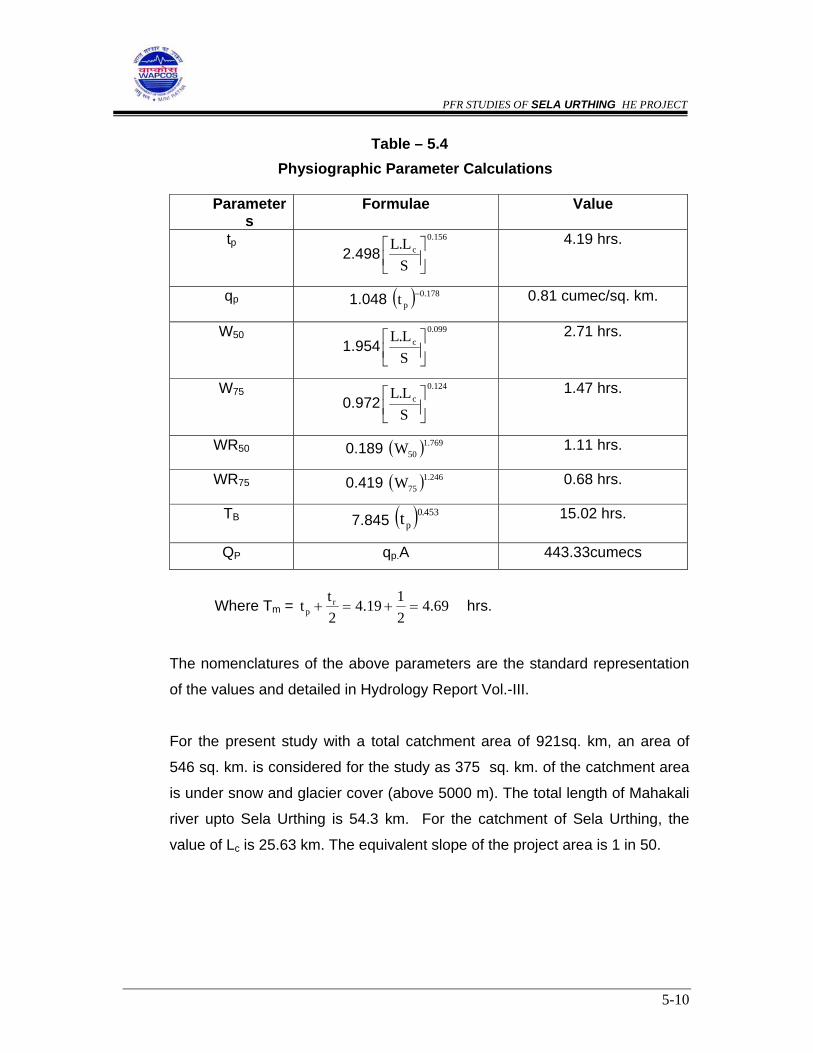
The formulae for calculation of various physiographic parameters are given in
Table 5.4.
PFR STUDIES OF SELA URTHING HE PROJECT
5-10
Table – 5.4 Physiographic Parameter Calculations
Parameter
s Formulae Value
tp
2.498156.0
c
SL.L
⎥⎦⎤
⎢⎣⎡
4.19 hrs.
qp 1.048 ( ) 178.0pt − 0.81 cumec/sq. km.
W50 1.954
099.0c
SL.L
⎥⎦⎤
⎢⎣⎡
2.71 hrs.
W75 0.972
124.0c
SL.L
⎥⎦⎤
⎢⎣⎡
1.47 hrs.
WR50 0.189 ( ) 769.150W 1.11 hrs.
WR75 0.419 ( ) 246.175W 0.68 hrs.
TB 7.845 ( ) 453.0pt 15.02 hrs.
QP qp.A 443.33cumecs
Where Tm = 69.42119.4
2tt r
p =+=+ hrs.
The nomenclatures of the above parameters are the standard representation
of the values and detailed in Hydrology Report Vol.-III.
For the present study with a total catchment area of 921sq. km, an area of
546 sq. km. is considered for the study as 375 sq. km. of the catchment area
is under snow and glacier cover (above 5000 m). The total length of Mahakali
river upto Sela Urthing is 54.3 km. For the catchment of Sela Urthing, the
value of Lc is 25.63 km. The equivalent slope of the project area is 1 in 50.

PFR STUDIES OF SELA URTHING HE PROJECT
5-11
5.2.3 Design Storm
a) Design Storm Depth The 1-day probable maximum precipitation
(PMP) value of Goriganga sub-basin is adopted as 33.41 cm. As the
Project area is situated in adjacent basin and no other relevant data is
available, the same point value has been adopted for the present
study purpose. The 25 year, 50 year and 100 return period precipitation
values (12cm, 14 cm & 16 cm respectively) are adopted from the
Isohyetal Maps.
b) Design Storm Duration The base period is of 15 hours, hence one
day design storm is considered.
c) Point to Areal Rainfall Ratios For 25 year, 50 year and 100 year
return period precipitation an areal reduction factor of 0.9098
corresponding to rainfed CA of 546 sq. km. is adopted The PMP value
of 33.41 cm considered for the study is an point value.
d) Clock Hour Correction A clock hour correction value of 1.15 is
adopted for PMF study for converting 1 day rainfall to 24 hr rainfall.
However the increase in one day value is limited to 50 mm.
e) Time Distribution Coefficients The Time Distribution Coefficients for
24 hours is given below:

PFR STUDIES OF SELA URTHING HE PROJECT
5-12
Table – 5.5 Distribution Coefficients
Time in hours
Distribution coefficient
Time in hours Distribution coefficient
1 0.17 13 0.79
2 0.27 14 0.82
3 0.36 15 0.84
4 0.43 16 0.86
5 0.48 17 0.88
6 0.53 18 0.90
7 0.58 19 0.92
8 0.63 20 0.94
9 0.67 21 0.96
10 0.70 22 0.98
11 0.73 23 0.99
12 0.76 24 1.00
f) Design Loss Rate A design loss rate of 0.5 cm/hr. has been adopted .
g) Design Base Flow and Glacial Melt A base flow rate of 0.05 cumecs
/ sq. km. has been adopted. In addition a glacier melt runoff value of 50
cumecs has also been considered tentatively, keeping view of existing
number of glaciers at the upper catchment boundary.
h) Critical Sequence of Rainfall Excess The critical sequence of rainfall
excesses are based on rainfall increments into design hyetograph
arranged in the form of two bell (12 hours each per day).

PFR STUDIES OF SELA URTHING HE PROJECT
5-13
5.2.4 Computation of Unit Hydrograph
Using the basic physiographic parameters, the unit hydrograph is plotted and
volume adjusted to 1 cm. With out changing the QP, Tm and TB . The surface
flow total flood hydrograph has been computed after the rainfall excess
increment arranged in a critical sequence along with additional component of
base flow and glacier melt.
The detailed calculations showing computation of equivalent slope,
physiographic parameters, rainfall excess, convolution and the flood
ordinates for PMP, 100 year, 50 year and 25 year return period for Sela
Urthing are given in the Hydrology Report Volume-III.
A PMF value of 4603.03 cumec has been adopted for purpose of preliminary
project planning. The hydrograph showing peak flood for PMF, 100 year, 50
year and 25 year floods is given in Table 5.6 and also presented in Plate 5.2.
Table – 5.6
Sela Urthing - Flood Ordinates
Return period Design flood peak in cumecs
Remarks
25 year 988.99
50 year 1257.01
100 year 1527.87
1000 year 4500.00 Projected from 25 year, 50 year &
100 year flood peaks using
Gumbel probability papers.
PMF 4603.03

PFR STUDIES OF SELA URTHING HE PROJECT
5-14
5.3 FLOOD FREQUENCY ANALYSIS
Flood frequency analysis provides a quick estimate of the design flood and is
also useful for checking the design flood values computed by other methods.
It is carried out in two methods viz – The Annual Maximum method and the
Peak over Threshold (POT) method (also known as partial duration method).
The long term annual instantaneous peak flow series at project site is not
available. As such the 32-year annual peak discharge series of Pancheswar
dam site has been used for frequency analysis. The results obtained will be
transposed to Sela Urthing site with due correlation for the variation of
catchment size. The available data will be subjected to randomness clock
stationary test, outlier test. Extreme value distribution also known as Gumbel
distribution and Log Peason Type III distribution are used for the present
study. Chi square test for LPT-III distribution and Gumbel distribution is used
to test the goodness of fit.
The calculations and conclusions are in the Hydrology Report Vol.-II. As
shown in the calculations, the Gumbel’s distribution is found to be better fit for
the flow series. The final results of various return period floods estimated at
Pancheswar are transposed to Garjia dam site using Dicken’s formula Q =
CA 3/4. The 10,000 year flood value for Pancheswar is 15041.36. Using this
relation, the 10000 year flood at Sela Urthing is found to be 2179.68 cumecs.
5.4 RESERVOIR SEDIMENTATION STUDIES
5.4.1 General
The suspended sediment inflow data is available at Chirkila G&D site near
project site from January '1985 to 15 December '1996 observed by M/s
NHPC. The observations have been taken by Punjab Type Bottle Sampler

PFR STUDIES OF SELA URTHING HE PROJECT
5-15
with grain size classification of coarse (greater than 0.2 mm), medium (0.025
mm to 0.2 mm) and fine (less than 0.075 mm).
The bed gradient of river (Maha kali) Dhauli ganga is steep ( 1in 50 –upto
project site) and the river is also fed from mountaineous catchment with a
number of glaciers which bring down considerable sediment load during snow
melt and flood season.
There is no Sediment data available for river Mahakali. Hence the Sediment
Data of adjacent Dhauliganga and Goriganga basins have been taken into
account for computing sediment inflow rate. The sediment inflow estimate for
Dhauliganga catchment (which is based on 10 years of data ) 0.14 ha – m /
100 sq. km. / year including 15% bed load which was agreed upon by CWC
while clearing Dhauliganga reservoir sedimentation studies. This estimate is
comparable with adjacent Goriganga basin sediment inflow of 0.15 ha-m/100
sq.km/year. The sediment rate considered for Pancheswar Multipurpose
Project (CA 12100 sq. km.) is 2.36 mm/hr which is based on six years of
Indian observation & 4 years of Nepalese observation. The rate included
20% bed load. The observations by Indian & Nepalese team show marked
difference. The silt rate recommended by Department of Science &
Technology is 1.65 mm/year for Himalayan rivers. As such the silt rate of
Pancheswar appears higher and more emphasis should be given towards
project specific observation data.
Since the above average annual rates are based on comparative shorter time
horizon an additional load of 15% is added for the adopted silt rate as to
make the silt rate representing a long time average. Hence a silt rate of
0.1725 ha-m / 100 sq. km./year (0.15 x 1.15) has been adopted for
sedimentation studies of Sela Urthing dam.
PFR STUDIES OF SELA URTHING HE PROJECT
5-16
5.4.2 Sedimentation aspects
It is observed from the topo sheets that both Dhauliganga and Kali the
catchments contain number of glaciers in the upper reaches at higher
elevation in beyond the proposed scheme Sela Urthing. There are few
reserved forests, dense mixed jungles of tansen , banj, deodar etc. open
scrubs, rockfall sites and moraine deposits carried by glaciers at relatively
lower stages near its confluence with the Kali. Major catchment area contains
bare rocks with little or no soil cover. The average annual sediment rate for
Sela Urthing has been estimated to be 1.725 mm based on observed
sediment data of Goriganga at Tham for 5 years and of Dhauliganga at
Chirkila for 10 years. The break up of suspended sediment particles for the
month of August 1988 (severe monsoon month) based on observed data at
Chirkila on the Dhauliganga is coarse 24.76%, medium 17.37% and fine
57.89%.
It is important to note that many Himalayan streams carry heavy sediment
loads. As such, planning of the project with a long feasible service time of say
70 years may become difficult. For Hydro electric project it is possible to
repay the development cost in a few years and the projects can be planned
effectively for relatively shorter period. For diversion structures across the
rivers, the nominal storage available between the dam crest level and the river
bed level is expected to be fully encroached by the rolling bed load of
pebbles, boulders etc. within one or two years and the entire rolling bed load
would pass over the crest. This warrants proper protection measures against
the damage of downstream glacis.
5.5 CONCLUSION & RECOMMENDATION
(1) The 10-daily flow series of 31 years developed and extended tentatively on
the basis of runoff-runoff correlation with Pancheswar flows may be adopted
for preliminary project planning. However, the flow series need to be reviewed

PFR STUDIES OF SELA URTHING HE PROJECT
5-17
when site specific observed flow series of longer periods would become
available from the observation agencies. Continuation of all hydro-
meteorological observation in the existing stations may be assured and
identification of new station may be under taken at DPR stage. A gauge,
discharge and silt observation site at/near Sela Urthing dam site should be
immediately installed on scientific basis.
(2) It is suggested that short interval rainfall-runoff observation should be initiated
at the project site to enable derivation of reliable unit hydrograph from
observed data. Similarly detailed storm studies are needed to be carried out
preferably by IMD in order to obtain reliable estimate of PMS at highly
orographic catchment with snow & glacier covers.
(3) The sediment rate adopted is based on observed suspended sediment data at
Dhauliganga and neighbouring Goriganga rivers for about 10 years only. The
bed load assumed to be 15% of suspended load is quite tentative. Therefore,
the sediment rate needs to be revised with updated observed data of longer
period. The contribution of bed load may be more precisely assessed
according to concentration of suspended load, type of materials forming
channel of the stream, texture of suspended material etc.
5.7 OBSERVATIONS OF CWC
The draft report of this project was submitted to CEA for perusal during
November 03. The observations received from CWC on the Hydrological
studies of this project and the replies for above observations, submitted by
WAPCOS are enclosed as Appendices 1.1 and 1.2 respectively.

Annexure - 5.2 ( d)
Time SPF 100 50 25Year Year Year
(hr) (m3/sec) (m3/sec) (m3/sec) (m3/sec)0 77.30 77.30 77.30 77.301 91.57 77.30 77.30 77.302 126.68 77.30 77.30 77.303 200.46 79.44 77.55 77.304 375.12 88.49 81.47 78.495 682.32 107.51 90.74 81.436 951.02 153.71 114.85 92.527 1335.33 254.43 175.24 124.148 1815.24 420.01 306.66 206.949 2351.33 620.92 473.92 335.57
10 3074.37 906.66 718.29 535.6511 3932.38 1253.89 1018.38 786.6612 4603.03 1527.87 1257.10 989.0013 3791.66 1196.00 968.99 743.7314 2882.61 835.07 659.38 484.8715 2271.97 618.31 485.41 353.1416 1603.26 417.48 337.14 257.1017 1108.62 304.93 252.10 199.2718 872.32 227.53 192.91 158.3019 698.55 174.25 151.95 129.6420 580.37 134.37 120.79 107.2221 515.41 106.87 99.37 91.8622 487.97 88.48 84.99 81.5123 528.50 80.65 79.31 77.9724 625.68 78.42 77.97 77.5225 591.85 77.30 77.30 77.3026 460.18 77.30 77.30 77.3027 365.56 77.30 77.30 77.3028 250.34 77.30 77.30 77.3029 190.65 77.30 77.30 77.3030 152.12 77.30 77.30 77.3031 125.91 77.30 77.30 77.3032 107.79 77.30 77.30 77.3033 94.56 77.30 77.30 77.3034 85.66 77.30 77.30 77.3035 80.23 77.30 77.30 77.3036 78.28 77.30 77.30 77.3037 77.30 77.30 77.30 77.3038 77.30 77.30 77.30 77.30
Sela Urthing - Design Flood OrdinatesTABLE - 8
5 -

Catchment Area = 840 Sq. Km Unit : Cumecs
Year Jan Feb Mar Apr May Jun Jul Aug Sep Oct Nov DecAnnual Average
20.56 16.92 24.58 23.33 34.60 65.57 87.08 157.67 138.45 50.07 28.19 20.261962 19.02 16.79 26.26 28.52 41.04 69.11 94.86 137.10 108.49 43.98 23.18 18.76 52.55
17.02 21.24 28.03 35.86 40.45 91.63 104.93 101.33 86.56 30.92 20.63 15.5616.19 12.14 17.50 18.62 33.84 62.19 95.59 156.25 129.10 40.68 26.33 19.75
1963 14.98 12.05 18.70 22.76 40.15 65.54 104.13 135.87 101.16 35.73 21.65 18.30 49.5513.40 15.24 19.96 28.62 39.57 86.90 115.19 100.42 80.72 25.12 19.26 15.1716.11 12.44 13.01 16.03 21.69 50.66 94.25 132.80 129.27 43.78 26.12 19.90
1964 14.91 12.34 13.89 19.59 25.73 53.39 102.68 115.47 101.29 38.46 21.47 18.43 44.9713.34 13.88 14.83 24.63 25.36 70.79 113.57 85.34 80.82 27.04 19.11 15.2816.49 13.39 17.28 19.97 26.42 53.33 73.59 107.46 92.35 29.93 21.49 16.80
1965 15.25 13.29 18.46 24.40 31.35 56.20 80.17 93.44 72.36 26.29 17.67 15.56 39.0113.65 16.80 19.70 30.69 30.89 74.52 88.67 69.06 57.74 18.48 15.73 12.9013.65 11.40 12.33 11.99 24.49 52.65 79.72 139.58 99.76 30.62 21.12 16.41
1966 12.63 11.31 13.17 14.65 29.05 55.49 86.84 121.37 78.17 26.90 17.37 15.20 40.4311.30 14.31 14.06 18.43 28.63 73.57 96.06 89.70 62.37 18.91 15.45 12.6113.57 10.36 10.98 11.70 17.93 46.70 83.83 141.77 113.40 36.98 23.84 18.59
1967 12.56 10.28 11.73 14.30 21.27 49.22 91.32 123.27 88.86 32.48 19.61 17.22 41.2411.24 13.00 12.53 17.99 20.96 65.26 101.02 91.11 70.90 22.84 17.45 14.2816.64 13.67 17.73 16.61 30.62 63.18 94.73 138.45 103.21 39.55 24.85 18.59
1968 15.39 13.56 18.94 20.29 36.32 66.59 103.20 120.39 80.88 34.73 20.43 17.22 45.8713.77 15.25 20.21 25.52 35.80 88.29 114.15 88.97 64.53 24.42 18.18 14.2816.49 12.74 15.59 16.70 36.85 58.35 84.41 135.77 132.67 47.41 27.78 20.04
1969 15.25 12.64 16.66 20.41 43.72 61.49 91.95 118.05 103.96 41.64 22.84 18.56 47.5113.65 15.99 17.78 25.67 43.09 81.53 101.71 87.25 82.95 29.28 20.33 15.3916.93 13.13 15.25 17.37 26.64 59.87 99.12 135.08 107.41 44.64 27.30 20.40
1970 15.66 13.03 16.29 21.23 31.60 63.10 107.98 117.45 84.16 39.21 22.45 18.89 46.2514.02 16.48 17.39 26.70 31.15 83.66 119.44 86.81 67.15 27.57 19.98 15.6717.08 13.65 18.51 22.28 28.36 81.96 102.32 149.54 130.90 48.42 31.66 22.91
1971 15.80 13.54 19.78 27.22 33.64 86.37 111.47 130.03 102.57 42.53 26.04 21.22 52.9914.14 17.13 21.11 34.24 33.16 114.52 123.30 96.10 81.84 29.90 23.17 17.6018.74 16.34 19.97 18.14 38.25 52.23 85.12 116.32 118.70 38.33 26.19 19.39
1972 17.33 16.21 21.34 22.17 45.38 55.04 92.73 101.15 93.01 33.67 21.53 17.96 44.9415.51 18.23 22.78 27.88 44.72 72.98 102.57 74.76 74.21 23.67 19.16 14.90
Mean Ten Daily Flow Series at Chhanger Chal (site no. 14) on Dhauliganga
Table - 5.3
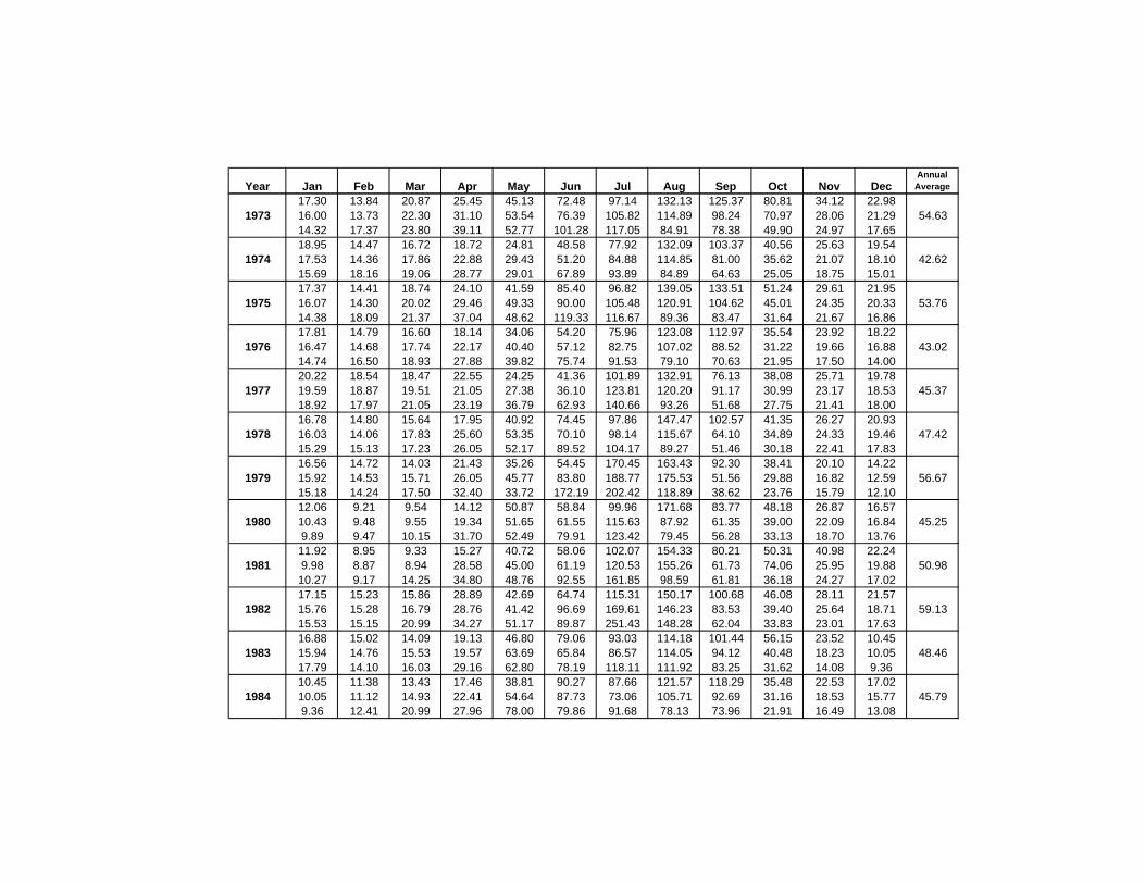
Year Jan Feb Mar Apr May Jun Jul Aug Sep Oct Nov DecAnnual Average
17.30 13.84 20.87 25.45 45.13 72.48 97.14 132.13 125.37 80.81 34.12 22.981973 16.00 13.73 22.30 31.10 53.54 76.39 105.82 114.89 98.24 70.97 28.06 21.29 54.63
14.32 17.37 23.80 39.11 52.77 101.28 117.05 84.91 78.38 49.90 24.97 17.6518.95 14.47 16.72 18.72 24.81 48.58 77.92 132.09 103.37 40.56 25.63 19.54
1974 17.53 14.36 17.86 22.88 29.43 51.20 84.88 114.85 81.00 35.62 21.07 18.10 42.6215.69 18.16 19.06 28.77 29.01 67.89 93.89 84.89 64.63 25.05 18.75 15.0117.37 14.41 18.74 24.10 41.59 85.40 96.82 139.05 133.51 51.24 29.61 21.95
1975 16.07 14.30 20.02 29.46 49.33 90.00 105.48 120.91 104.62 45.01 24.35 20.33 53.7614.38 18.09 21.37 37.04 48.62 119.33 116.67 89.36 83.47 31.64 21.67 16.8617.81 14.79 16.60 18.14 34.06 54.20 75.96 123.08 112.97 35.54 23.92 18.22
1976 16.47 14.68 17.74 22.17 40.40 57.12 82.75 107.02 88.52 31.22 19.66 16.88 43.0214.74 16.50 18.93 27.88 39.82 75.74 91.53 79.10 70.63 21.95 17.50 14.0020.22 18.54 18.47 22.55 24.25 41.36 101.89 132.91 76.13 38.08 25.71 19.78
1977 19.59 18.87 19.51 21.05 27.38 36.10 123.81 120.20 91.17 30.99 23.17 18.53 45.3718.92 17.97 21.05 23.19 36.79 62.93 140.66 93.26 51.68 27.75 21.41 18.0016.78 14.80 15.64 17.95 40.92 74.45 97.86 147.47 102.57 41.35 26.27 20.93
1978 16.03 14.06 17.83 25.60 53.35 70.10 98.14 115.67 64.10 34.89 24.33 19.46 47.4215.29 15.13 17.23 26.05 52.17 89.52 104.17 89.27 51.46 30.18 22.41 17.8316.56 14.72 14.03 21.43 35.26 54.45 170.45 163.43 92.30 38.41 20.10 14.22
1979 15.92 14.53 15.71 26.05 45.77 83.80 188.77 175.53 51.56 29.88 16.82 12.59 56.6715.18 14.24 17.50 32.40 33.72 172.19 202.42 118.89 38.62 23.76 15.79 12.1012.06 9.21 9.54 14.12 50.87 58.84 99.96 171.68 83.77 48.18 26.87 16.57
1980 10.43 9.48 9.55 19.34 51.65 61.55 115.63 87.92 61.35 39.00 22.09 16.84 45.259.89 9.47 10.15 31.70 52.49 79.91 123.42 79.45 56.28 33.13 18.70 13.7611.92 8.95 9.33 15.27 40.72 58.06 102.07 154.33 80.21 50.31 40.98 22.24
1981 9.98 8.87 8.94 28.58 45.00 61.19 120.53 155.26 61.73 74.06 25.95 19.88 50.9810.27 9.17 14.25 34.80 48.76 92.55 161.85 98.59 61.81 36.18 24.27 17.0217.15 15.23 15.86 28.89 42.69 64.74 115.31 150.17 100.68 46.08 28.11 21.57
1982 15.76 15.28 16.79 28.76 41.42 96.69 169.61 146.23 83.53 39.40 25.64 18.71 59.1315.53 15.15 20.99 34.27 51.17 89.87 251.43 148.28 62.04 33.83 23.01 17.6316.88 15.02 14.09 19.13 46.80 79.06 93.03 114.18 101.44 56.15 23.52 10.45
1983 15.94 14.76 15.53 19.57 63.69 65.84 86.57 114.05 94.12 40.48 18.23 10.05 48.4617.79 14.10 16.03 29.16 62.80 78.19 118.11 111.92 83.25 31.62 14.08 9.3610.45 11.38 13.43 17.46 38.81 90.27 87.66 121.57 118.29 35.48 22.53 17.02
1984 10.05 11.12 14.93 22.41 54.64 87.73 73.06 105.71 92.69 31.16 18.53 15.77 45.799.36 12.41 20.99 27.96 78.00 79.86 91.68 78.13 73.96 21.91 16.49 13.08
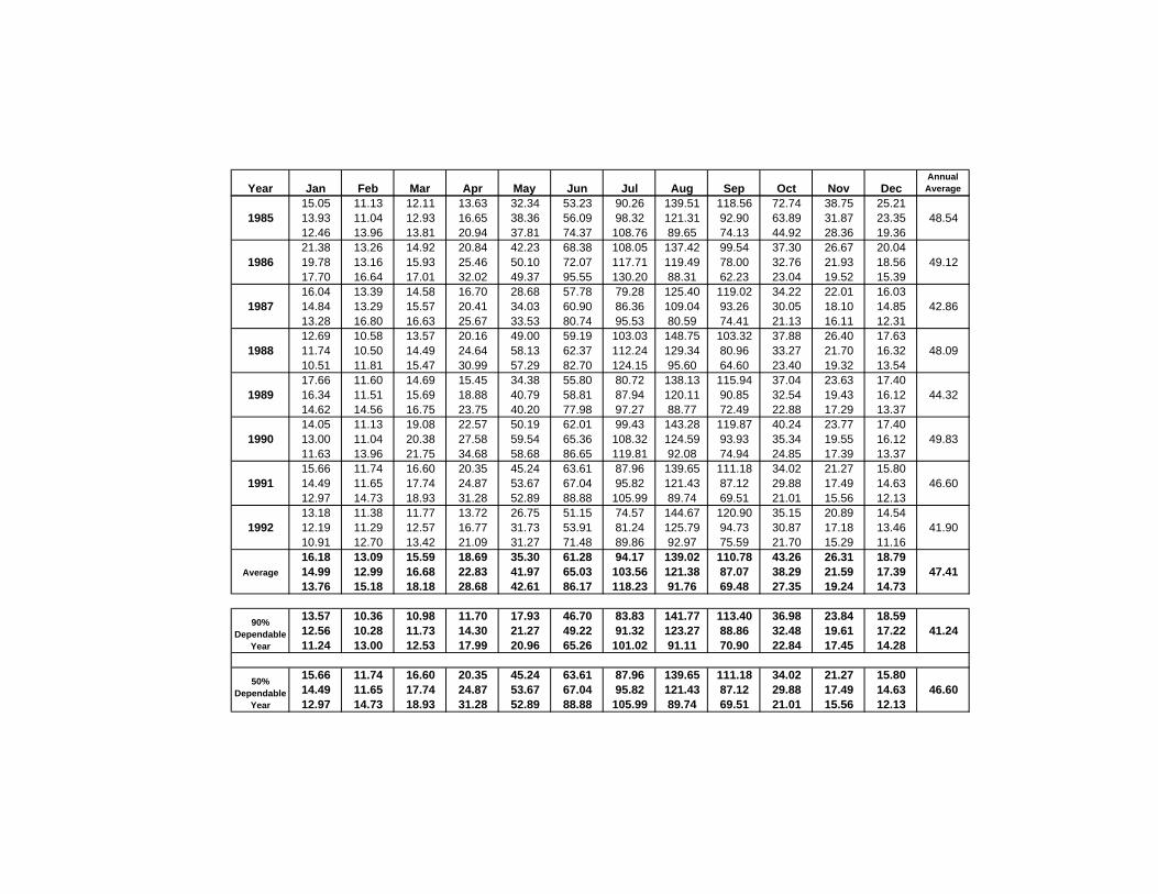
Year Jan Feb Mar Apr May Jun Jul Aug Sep Oct Nov DecAnnual Average
15.05 11.13 12.11 13.63 32.34 53.23 90.26 139.51 118.56 72.74 38.75 25.211985 13.93 11.04 12.93 16.65 38.36 56.09 98.32 121.31 92.90 63.89 31.87 23.35 48.54
12.46 13.96 13.81 20.94 37.81 74.37 108.76 89.65 74.13 44.92 28.36 19.3621.38 13.26 14.92 20.84 42.23 68.38 108.05 137.42 99.54 37.30 26.67 20.04
1986 19.78 13.16 15.93 25.46 50.10 72.07 117.71 119.49 78.00 32.76 21.93 18.56 49.1217.70 16.64 17.01 32.02 49.37 95.55 130.20 88.31 62.23 23.04 19.52 15.3916.04 13.39 14.58 16.70 28.68 57.78 79.28 125.40 119.02 34.22 22.01 16.03
1987 14.84 13.29 15.57 20.41 34.03 60.90 86.36 109.04 93.26 30.05 18.10 14.85 42.8613.28 16.80 16.63 25.67 33.53 80.74 95.53 80.59 74.41 21.13 16.11 12.3112.69 10.58 13.57 20.16 49.00 59.19 103.03 148.75 103.32 37.88 26.40 17.63
1988 11.74 10.50 14.49 24.64 58.13 62.37 112.24 129.34 80.96 33.27 21.70 16.32 48.0910.51 11.81 15.47 30.99 57.29 82.70 124.15 95.60 64.60 23.40 19.32 13.5417.66 11.60 14.69 15.45 34.38 55.80 80.72 138.13 115.94 37.04 23.63 17.40
1989 16.34 11.51 15.69 18.88 40.79 58.81 87.94 120.11 90.85 32.54 19.43 16.12 44.3214.62 14.56 16.75 23.75 40.20 77.98 97.27 88.77 72.49 22.88 17.29 13.3714.05 11.13 19.08 22.57 50.19 62.01 99.43 143.28 119.87 40.24 23.77 17.40
1990 13.00 11.04 20.38 27.58 59.54 65.36 108.32 124.59 93.93 35.34 19.55 16.12 49.8311.63 13.96 21.75 34.68 58.68 86.65 119.81 92.08 74.94 24.85 17.39 13.3715.66 11.74 16.60 20.35 45.24 63.61 87.96 139.65 111.18 34.02 21.27 15.80
1991 14.49 11.65 17.74 24.87 53.67 67.04 95.82 121.43 87.12 29.88 17.49 14.63 46.6012.97 14.73 18.93 31.28 52.89 88.88 105.99 89.74 69.51 21.01 15.56 12.1313.18 11.38 11.77 13.72 26.75 51.15 74.57 144.67 120.90 35.15 20.89 14.54
1992 12.19 11.29 12.57 16.77 31.73 53.91 81.24 125.79 94.73 30.87 17.18 13.46 41.9010.91 12.70 13.42 21.09 31.27 71.48 89.86 92.97 75.59 21.70 15.29 11.1616.18 13.09 15.59 18.69 35.30 61.28 94.17 139.02 110.78 43.26 26.31 18.79
Average 14.99 12.99 16.68 22.83 41.97 65.03 103.56 121.38 87.07 38.29 21.59 17.39 47.4113.76 15.18 18.18 28.68 42.61 86.17 118.23 91.76 69.48 27.35 19.24 14.73
13.57 10.36 10.98 11.70 17.93 46.70 83.83 141.77 113.40 36.98 23.84 18.5912.56 10.28 11.73 14.30 21.27 49.22 91.32 123.27 88.86 32.48 19.61 17.22 41.2411.24 13.00 12.53 17.99 20.96 65.26 101.02 91.11 70.90 22.84 17.45 14.28
15.66 11.74 16.60 20.35 45.24 63.61 87.96 139.65 111.18 34.02 21.27 15.8014.49 11.65 17.74 24.87 53.67 67.04 95.82 121.43 87.12 29.88 17.49 14.63 46.6012.97 14.73 18.93 31.28 52.89 88.88 105.99 89.74 69.51 21.01 15.56 12.13
90% Dependable
Year
50% Dependable
Year
PFR STUDIES OF SELA URTHING HE PROJECT
6-1
CHAPTER-VI
CONCEPTUAL LAYOUT AND PLANNING
6.1 INTRODUCTION
The Sela Urthing hydro-electric project as planned envisages construction of
a 73 m high concrete gravity dam above the deepest foundation level across
the river Dhauliganga about 450 m downstream of Sela Village. The dam is
located upstream of the confluence of Sela Yankti with Dhauliganga river. The
water from the diversion dam will be led to a surface power house located
downstream of the confluence of Mislilng Gad and Syanyar Ki Dhar with
Dhauliganga river and about 1 km downstream of Urthing village on the right
bank of the river through a 2.01km long head race tunnel, a surge shaft and
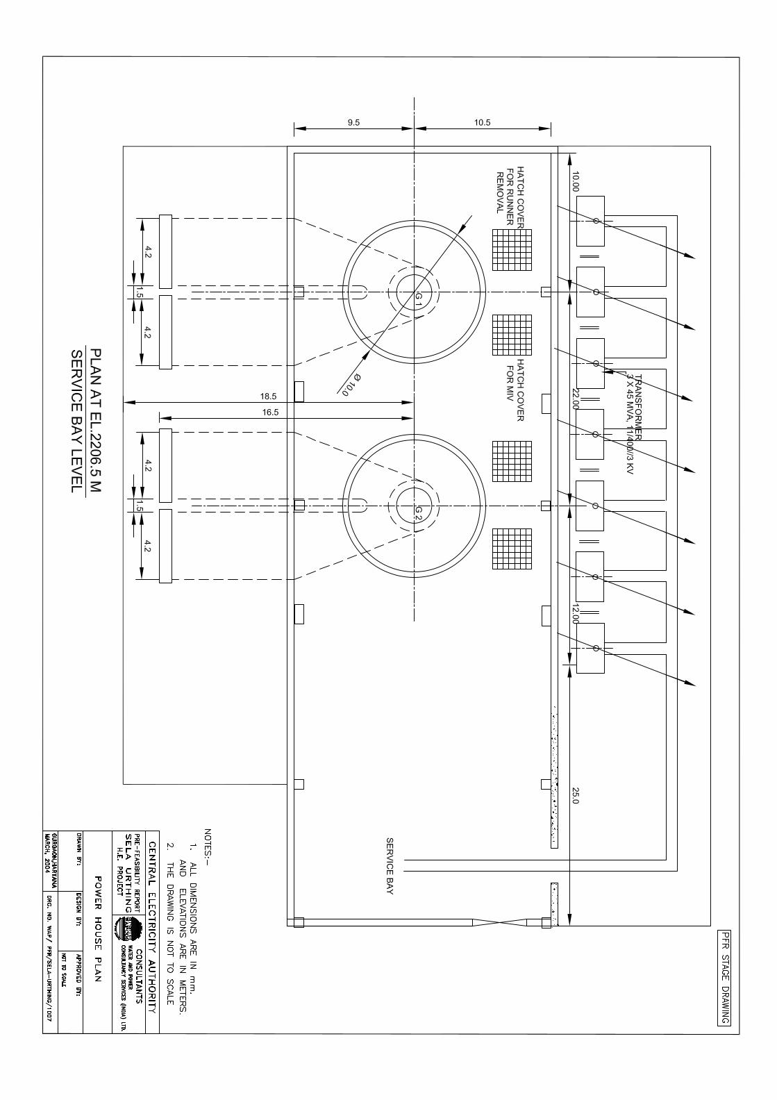
penstocks. The power house as planned with an installed capacity of 230 MW
(2x115MW) utilises a rated head of 255.5 m.
Central Electricity Authority in its planning had envisaged the diversion
structure near Sela, with FRL 2480 m and the power house near Urthing at
TWL 2200 m. CEA had anticipated a 4.5 km long channel aligned on the right
bank of the river. As per CEA, the scheme envisaged utilization of a head of
280m with an optimum generating capacity of 165 MW. After detailed studies,
the dam site has been selected downstream of village Sela where the river
bed level is at about EL 2415 m with FRL 2470 m and the river flows in a
narrow gorge of 80 to 90 m width. The site is ideally suited for a dam
considering the rock both for the dam and abutment foundations. The intake
and a 2.01 km HRT are planned on the right flank of the river and the power
house on the existing river terrace downstream of the confluence of Misling
Gad and Syanyar Ki Dhar with Dhauliganga river. The minimum T.W.L at the
power house is 2200 m and this corresponds to the FRL of Urthing Sobala
H.E. scheme as planned by CEA. The scheme as planned envisages
PFR STUDIES OF SELA URTHING HE PROJECT
6-2
utilization of gross head of 270 m with optimum generating capacity of
230 MW..
The location of the dam and its height have been finalised considering
optimum power generation, topographical and geotechnical features, already
planned projects on the upstream and downstream, economy, submergence
and other relevant factors. The site is ideally suited for the construction of a
concrete dam. Embankment type of dam was not considered in view of non-
availability of impervious materials in the near vicinity and spillway
considerations.
The dam which will be 185 m long at the top is provided with spillway and
non-over flow blocks. The spillway blocks are designed as sluice control
structures with a crest level of 2440 m and 8x12 m size sluice. The FRL and
MWL of the dam are at EL 2470 m and the top of dam is kept at EL 2473 m
after allowing for necessary freeboard. The MDDL is kept at EL 2455 m which
will provide the required peaking storage against the gates during the lean
months and also meets the requirement of power intake.
The intake, desliting chambers, HRT, surge shaft and penstocks are located
in competent rocks, which is not likely to pose any construction problems. The
surface power house located on the river bank will also have adequate
foundation conditions at a reasonable depth.
The salient features of the project are included in the report. The details of the
major components of the project alongwith the design considerations are
given in the subsequent paragraphs.
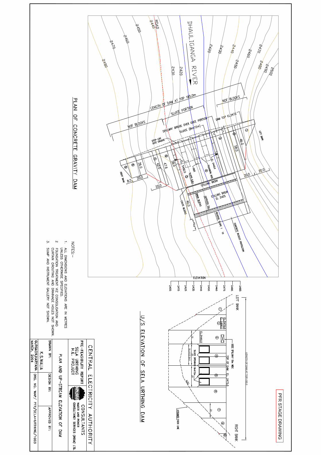
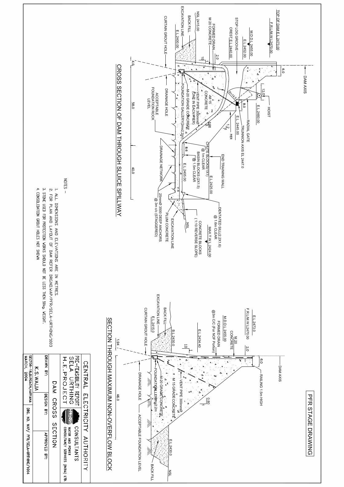
6.2 DIVERSION STRUCTURE
A 73 m high (above deepest foundation level) concrete gravity dam is
proposed on Dhauliganga river about 450m downstream of Sela village. The

PFR STUDIES OF SELA URTHING HE PROJECT
6-3
dam is proposed at latitude 30o 08’29” N and longitude 80o 36’23” E. The
concrete dam will have a FRL of 2470 m and MDDL of 2455 m. The MWL of
the dam is 2470 m and the top of the dam is kept at EL 2473 after taking into
account the required free board.
The proposed dam will have a submergence area of 1,57,226 sq. m at FRL
and all this area will be within the river gorge. The reservoir storage for
peaking purposes in the lean season between MDDL and FRL is 1.705 M.
Cum.
Two number of sluice spillway blocks with 2 number sluices of size 8x12 m
per bay have been planned to pass the design flood discharge of 4603.03
cumecs. The sluice invert has been planned at EL 2440m. For the spillway,
stilling basin has been planned as terminal structure for energy dissipation
with concrete apron protection downstream. The dam will have six number
NOF blocks, two number sluice spillway blocks of 28 m length each. The
pier width for the spillway has been kept as 6 m. each. In addition, one block
with ogee spillway of 18 m length has also been provided. The choice of
stilling basin energy dissipation works for this dam has been adopted based
on the tail water conditions. The sluice openings are provided with 8x12 m
high radial gates.
The foundation rocks both at the river bed and abutments are found to be
quite competent and no major geological discontinuities exist. As a foundation
treatment measure consolidation grouting throughout the entire base of the
dam to a depth of 10 m and one row of curtain grouting to a depth of h/2
where “h” is the height between FRL and deepest foundation level subject to a
minimum depth of 10 m have been provided. A grouting cum drainage gallery
has been provided at the bottom of the dam, through which the curtain
grouting as well as drainage hole works will be done.

PFR STUDIES OF SELA URTHING HE PROJECT
6-4
All the hydraulic and structural designs for the dam, spillway and other
components of the dam have been done as per relevant BIS codes /
standards and the State of the art practices. The dam sections will also be
zoned with different grades of concrete in order to economise the cost without
sacrificing the stability and safety requirements.
The dam will also be provided with measuring devices as per BIS codes to
observe and monitor the behaviour of the dam structures.
The layout plan of the dam and other components of the project is in drawing
no. WAP/PFR/SELA-URTHING/1001. The dam plan and elevation in drawing
no WAP/PFR/SELA-URTHING/1003. The sectional details of NOF and over
flow blocks are in drawing no. WAP/PFR/SELA-URTHING/1004. .
6.3 POWER INTAKE
The intake structure for diverting the design discharge of 125.181 cumec
(including silt flushing requirement) is proposed on the right bank of river
Dhauliganga about 70 m upstream of the proposed diversion dam. The intake
invert is proposed at EL 2441.40 m keeping in view the requirements of power
intakes like sufficient cushion of water, reservoir siltation etc. Suitable
desilting arrangement has been provided to remove particles of size 0.2 mm
and above by providing a desilting chamber.
The required flows for power generation are proposed to be diverted through
2 no. independent identical intake structures of capacity 62.59 cumec each
and 26.5 m apart c/c with crest at EL.2444.5 m. Each of the two intakes will
have 5 spans of 5 m each trashracks separated by 4 no. piers of 1.5 m
width each at center to center distance of 6.5 m. The total width of the intake
will, therefore, be 54 m. The trashracks will be in panels of size 5 m x 1.5 m
which can be easily lowered in inclined trash rack grooves. The racks will
be made out of steel flats of size 10 mm x 50 mm rounded at inlet ends

PFR STUDIES OF SELA URTHING HE PROJECT
6-5
and shall be fixed vertically on each of these panels at a spacing of 50 mm
c/c. Assuming 50% clogging, the velocity through trashracks will be restricted
to 0.75 m/s.
The flows through each intake will be led to an intake tunnel with a bell mouth
entry. The vertical lift gates of size 4 m x 4 m will control the flow into the
intake tunnels. Provision for Stop Log grooves have also been made for the
intakes but no provision for slop longs has been made in the estimate
because it is felt that the intake gates itself function as stop logs. For
operation of gates, a gate hoisting structure will be provided at EL 2473 m.
A vent pipe of 200 mm diameter would also be provided just downstream of
the intake gates. Alongwith structure for gate hoists, a deck has also been
proposed at EL 2456 m to install / clear the trashracks when reservoir level
reaches MDDL. The details of intake structure are shown in Drawing No.
WAP/PFR/SELA URTHING/1005. The hill slope near each intake will be
stabilized with adequate slope protection measures like rock bolts, shotcrete,
benching, drainages etc. as necessary.
6.4 INTAKE TUNNELS
Two number intake tunnels have been proposed, one each for the two
independent intake structures. Each of these tunnels is designed to carry
62.59 cumec discharges. The tunnels will be D - shaped with a finished
diameter of 4.0 m and will meet independent desilting chambers. At the end of
each desilting chamber a gate control shaft would be provided which will
control flow into tunnels of same size leading to HRT. These tunnels will
merge into a single headrace tunnel which will carry the total flow further upto
a surge shaft. The length of each intake tunnel will vary to suit the merger
point with the headrace tunnel. To excavate these tunnels, rock support
system shall be provided to suit the geological conditions of the strata through
which these are excavated. The intake tunnels will be provided with 250 mm
thick PCC lining.

PFR STUDIES OF SELA URTHING HE PROJECT
6-6
6.5 DESILTING CHAMBERS
It is proposed to provide desilting chambers to flush out all silt particles of
0.2 mm size and above.
Two no. trough type underground desilting chambers operating under
pressure flow conditions are proposed. These are fed by independent intake
tunnels. Each desilting chamber will be 12.5 m wide, 18.0 m deep and 220 m
long and will have smooth transitions at inlet and outlet ends to avoid eddy
formations.
The desilting chamber troughs will have 2 m x 2 m longitudinal drains at bed
level. These drains will be covered with removable slabs having 250 mm to 25
mm dia holes at 4.0 m c/c through which the silt particles that settle will pass
to the silt collecting drains. At the end of desilting chambers, gates are
provided in an underground hoist chamber to flush out silt laden waters in the
drains to a common silt flushing tunnel that takes the silt-laden waters back to
the river. These silt flushing gates of size 2.0 x 2.0 m can be radial gates. An
opening of about 20 cm height of these gates will induce sufficient silt flushing
velocity to flush out the accumulated silt in the drains. The silt flushing
discharge passing through each gate opening would be about 12.52 m3/s.
6.6 HEAD RACE TUNNEL
A single horseshoe shaped headrace tunnel of 5.5 m finished diameter and
about 2.01 km length has been designed to carry the required flows further
upto the surge shaft. This tunnel is designed to carry a discharge of 100.14
cumec. This tunnel will cross three deep nallahs on its route and therefore its
alignment has been so fixed that it crosses the nallahs well below it with
adequate rock cover. The other smaller nallahs are not likely to affect its
alignment. The tunnel will be provided with suitable rock support system
depending upon the geological strata / formations enroute. Apart from the

PFR STUDIES OF SELA URTHING HE PROJECT
6-7
rock support system, the headrace tunnel will be provided with 300 mm thick
plain cement concrete lining to reduce the head loss due to friction.
The details of typical rock support system and the concrete lining of headrace
tunnel are shown in Drawing No. WAP/PFR/SELA-URTHING/1006.
6.7 SURGE SHAFT
To take care of pressure rise in case of sudden load rejection and to meet the
sudden demand of water in case of sudden load acceptance, a simple surge
shaft of 10 m diameter and maximum surge elevation of 2502.0 m has been
provided at the end of headrace tunnel. This proposed surge shaft will serve
the following functions:-
(i) To provide a free water surface close to the flow regulating
mechanism.
(ii) To limit the length of pressurised water conduit liable to water
hammer.
(iii) To store water during load rejection until the conduit velocity has been
decelerated to the new steady state velocity, and
(vi) To supply the additional flows required by the turbine during the load
acceptance until the headrace tunnel is accelerated to new steady
state value.
The bottom of surge shaft will be at EL 2433.6 m and the normal minimum
water level and maximum surge levels will be 2448 m & 2502 m respectively.
The top of surge shaft will be located at EL. 2504 m. In case during detail
design, it is found that minimum surge level comes lower than crown of HRT,
expansion chambers of suitable capacity can be considered. Alternately, the
type of surge shaft can be changed to restricted orfice type.

PFR STUDIES OF SELA URTHING HE PROJECT
6-8
The surge shaft is provided with adequate rock support system and a
reinforced concrete lining of 500 mm thickness upto maximum surge level.
Thereafter, upto the top level, only rock support system and 150 mm
shotcreting will be sufficient.
6.8 PENSTOCKS
One no. surface penstock of 4.8 m diameter bifurcating into 3.4 m each two
near the power house is proposed to provide independent supply of water to
the individual units of turbines. Flow into the penstock shall be controlled by
a gate provided in the surge shaft. Flow of each of the feeder penstock to
turbines shall be controlled by a butterfly valve (MIV) in the power house.
The thickness of the penstock shall vary from 14mm in the beginning to 20
mm near the power house. Suitable anchor blocks shall be provided along
the length of the penstocks at bend locations and saddle supports shall be
provided in between the anchor blocks. Expansion joints shall be provided
immediately downstream of each anchor block.
6.9 POWER HOUSE
A surface power house is proposed on the right bank of river Dhauliganga
downstream of confluence of Misling Gad on the left bank and Syanyar Ki
Dhar on the right bank with Dhauliganga river. This power house will have 2
units of 115 MW each operating under a maximum gross head of 270 m.
The rated head of turbines is, however, proposed as 259.55 m. It is proposed
to install 2 no. vertical axis Francis turbines in this power house. The center
lines of these turbines will be at EL 2194 m.
The power house building will be 20.0 m wide and 69 m long including service
bay of 25 m length. An EOT crane with a span of 19.0 m is proposed to run
along two crane beams supported on columns along B and D lines. The
main power house building is covered by precast concrete slabs over a roof

PFR STUDIES OF SELA URTHING HE PROJECT
6-9
comprising 10 nos N type roof trusses and purlins. The roof slab will be
covered with suitable water proofing arrangement. The roof shall have
adequate roof drainage arrangements.
An auxiliary bay is proposed on the down side of main building and a draft
tube deck is provided at EL 2206.5 m with gate groove openings for the draft
tube gates. The hoisting mechanism for these gates would be a moving
gantry provided with lifting beam. A suitable rail track will be provided for
movement of the gantry. A storage arrangement for the draft tube gates,
when not in use, will be provided in the form of grooves below the deck
approach. These grooves will be located in the line of rail track for movable
gantry. The gates will be hung in these grooves and covered with chequered
steel plates.
The transformer deck will be provided upstream of main powerhouse building
for installation of transformers. The plan and x-section of power house is
shown in drawing nos. WAP/PFR/SELA-URTHING/1007 & 1008.
The service bay will be approached by an approach road connected to the
existing right bank road/path.
6.10 TAIL RACE
The tail waters from the draft tubes will be led to a tail pool. The bottom
elevation of tail pool near the draft tubes shall be at 2188.5 m and the tail pool
floor will be given a reverse slope of 1 in 5 till it reaches an elevation of 2199.8
m. The bottom of the tail pool will be designed for uplift pressure when empty.
Depending upon the site conditions either the base slab will be anchored to
the foundation rock (if available) or suitable under drainage by pressure
release valves along with inverted filter will be provided.

PFR STUDIES OF SELA URTHING HE PROJECT
6-10
The tail pool will have vertical walls on both sides of pool and 2 m wide weir
has been proposed at the downstream end of tail pool with a crest level of
2199.8 m. This weir can pass a discharge of 5.0 m3/s over it at minimum TWL
of 2200.0 m. The normal tail water level is estimated at 2203.0 m.
After the tail pool a tail race channel shall be provided upto the river. This
TRC will have a bed slope of 1:1000 and a full supply depth of 3.0 m. The
tail race shall be a trapezoidal lined section with a bed width of 12.75 m and a
side slope of 1 in 1.5.
6.11 ELECTROMECHANICAL WORKS
The proposed 230 MW Sela Urthing Hydro-Electric Project would be Run of
the river development. The installed capacity would be provided by 2 nos. of
Francis, Vertical axis turbine driven generating units of 115 MW each housed
in a surface powerhouse. It is proposed to provide Inlet Valve of spherical
type for each turbine, which would be accommodated in the powerhouse
cavern.
The generation voltage of 11 kV would be stepped up to 220 kV through three
45 MVA, 11/220/√3 kV single-phase step up transformers for each unit
located adjacent to upstream wall of the powerhouse. The 11 kV isolated
phase busducts would connect the 11 kV generator terminals with 11 kV
bushings of step up transformers. The 220 kV bushings of the transformers
would be connected with 220 kV outdoor switchyard located near the
powerhouse.
The arrangement of generating equipments, unit step up transformers, etc. is
indicated in the following drawings.
1. Plan of the Power House at service bay level - WAP/PFR/SELA URTHING/1007
2. Cross-section of the Power House - WAP/PFR/SELA URTHING/1008

PFR STUDIES OF SELA URTHING HE PROJECT
6-11
The power generated would be evacuated through one double circuit 220 kV
transmission line. The single line diagram is enclosed given in Drawing NO.
WAP/PFR/SELA URTHING/1009.
6.1 2 BRIEF PARTICULARS OF EQUIPMENTS
Turbine and Governor The upstream levels, tailrace level and head available for power generation
are indicated below:
i) Upstream Levels
• FRL EL 2470.0 M
• MDDL EL 2455.0 M
ii) Tailrace Levels
• Maximum EL 2203.0 M
• Minimum EL 2200.0 M
iii) Heads
• Maximum net head 262.0 M
• Minimum net head 244.0 M
• Rated head 255.5 M
The specific speed of the turbine determined as 120 RPM leads to the choice
of Francis turbine for this station. The turbine would be suitably rated to
provide 115 MW at generator terminals at rated head of 255.5 M. The speed
of turbine has been determined as 300 RPM. The centre of turbine runner has
been set at EL 2194 M, 6 m below the minimum TWL which is at EL 2200.0
M. The governor would be electro-hydraulic digital PID type suitable for fully
automatic control. The closing time of wicket gates would be so adjusted so
PFR STUDIES OF SELA URTHING HE PROJECT
6-12
as not to increase the speed rise and pressure rise more than 45% and 30%
respectively under full load throw off condition.
6.13 MAIN INLET VALVE
It is proposed to provide Inlet Valve of the Spherical type for each turbine as
second line of defence in stopping the water flow to the turbine when due to
governor malfunctioning, the generating units may tend to go to runaway
speed. During the time when the generating unit is under stand still condition,
it would help in minimizing the water leakage through the wicket gates of the
turbine. The opening of the valve would be achieved through pressurized oil
servomotor and closing through counter weight.
6.14 GENERATOR AND EXCITATION SYSTEM
The generator shaft would be directly coupled with the turbine shaft. The
bearing arrangement would be semi-umbrella type with combined thrust and
guide bearings below the rotor and one guide bearing above the rotor. The
generator would be of the closed air circuit water cooled type. The main
parameters of the generator would be as indicated below:
i) Rated out put - 115 MW
ii) Power factor - 0.9 lag
iii) Speed - 300 RPM
iv) Class of Insulation of
stator and rotor winding - Class 'F'
v) Generation Voltage - 11 kV
The generators would be provided with static excitation equipment and
voltage regulator. Necessary power for excitation would be provided by
tapping the generator terminals. Necessary fire/temp. detectors and two

PFR STUDIES OF SELA URTHING HE PROJECT
6-13
banks of CO2 cylinder would be provided for fire protection of the generator.
Optimisation of generation voltage would need to be carried at DPR stage.
6.15 UNIT STEP-UP TRANSFORMER
Three 45 MVA, 11/220/√3 kV single-phase transformers, would be provided
for each generating unit with one spare transformer of same rating common
for all the units. The likely transport limitations have dictated the choice for
Single-phase transformers. The transformers would be located outside near
upstream wall of power house. The 11 kV bushing of the transformers would
be connected with 11 kV terminals of generator through 11 kV busducts. The
220 kV bushings would be connected with 220 kV outdoor switchyard located
near the upstream wall of power house through link lines.
6.16 EOT CRANE
The heaviest equipment which the powerhouse cranes are required to handle
during erection and subsequently during maintenance is the generator rotor.
The weight of the generator rotor has been estimated to be about 360 tonnes.
It is proposed to provide the two EOT cranes of 200/20 tonnes capacity each.
6.17 AUXILIARY EQUIPMENT AND SYSTEMS FOR THE POWER HOUSE
Following equipments for the auxiliary systems of the power house would be
provided:
i) Cooling water system for turbines, generators, unit step up
transformers etc.
ii) Drainage System
iii) Dewatering system
iv) High pressure compressed air equipment for governor and MIV etc.
v) Low pressure compressed air equipment for station services
PFR STUDIES OF SELA URTHING HE PROJECT
6-14
vi) 415 V LTAC supply system comprising station service transformers,
unit auxiliary transformer, station service board, unit auxiliary boards
etc.
vii) D.C. supply system comprising 220 V DC battery, chargers, DC
distribution boards etc.
viii) Ventilation system for the power house
ix) Air conditioning system for control room, conference room etc.
x) Illumination system
xi) Earthing system
xii) Oil handling system
xiii) Power and control cables
xiv) Fire protection system
6.18 220 kV SWITCHYARD
It is proposed to provide 220 kV Outdoor Switchyard on the upstream side
near the power house having 6 bays. 2 bays for generator incomings, 2 bays
for 220 kV transmission lines, 1 bay for step down transformer and 1 bay for
bus coupler. The double bus bar arrangement has been proposed which
would provide flexibility and reliability in the operation of the plant.
6.19 OBSERVATIONS OF CEA & CWC
The Draft Report of this project was submitted to CEA for perusal during
November 03. The observations received from the various directorates of
CWC and CEA on the civil and electrical aspects of the projects have been
considered and taken care in this report. The detailing has been kept to the
possible extent as the report pertains to the preliminary feasibility stage
studies.
PFR STUDIES OF SELA URTHING HE PROJECT
7-1
CHAPTER-VII
POWER POTENTIAL STUDIES
7.1 GENERAL
The power potential studies have been carried out for Sela Urthing Hydel
Scheme, which is located in Uttranchal State. The projected power supply
position for 11th Plan indicate that there would be shortage of peak power
in Uttranchal State as well as in Northern region. The execution of this
project would help in reducing the gap between supply and demand of
power.
This is a Run off the river development with diurnal storage for peaking
purpose. The power house would be of surface type.
The scheme is located down stream of Bokang Bailing H.E Project which
has been planned as storage based scheme. Therefore, this scheme has
been planned considering regulated discharges from Bokang Bailing H.E
Project. The flows are also passing through Chhungur Chal H.E Project
(runoff the river scheme) located at its downstream. Benefits have also
been determined for an alternative scheme with unregulated inflows
received.
7.2 FIXATION OF FRL/MDDL
The FRL of the pondage has been fixed at EL 2470.0 M so as to get
adequate storage capacity for peaking operation of the plant during lean
flow period (January, February and March). The FRL has also been
coordinated with Minimum TWL of upstream Chhungur Chal HE project
which is at EL 2470 M. The MDDL of EL 2455 M has been fixed keeping
the requirement of minimum cushion of water above the head race tunnel

PFR STUDIES OF SELA URTHING HE PROJECT
7-2
(HRT) to rule out the air entrainment into the HRT. The storage at FRL is
computed as 3.060 million cubic metres whereas the storage at MDDL is
estimated as 1.355 million cubic metres, thus making available live storage
of 1.705 million cubic metres. The levels v/s capacity characteristics of the
pondage are indicated in Annex 7.1.
7.3 FIXATION OF TAIL RACE WATER LEVEL (TWL)
The minimum tail water level which corresponds to discharge of one
generating unit at 10% load has been considered as EL 2200 M. The
Maximum TWL at EL 2203 M corresponds to all the units running at full
load.
These levels however would need to be verified when it would be possible
to prepare tail rating curve.
7.4 WATER AVAILABILITY
The available data of water flows on 10 daily basis has been analysed in
Chapter No. 5 on “hydrology”. Water flows series for 30 years (1962-63 to
1991-92) has been utilized for power potential studies and is indicated in
Annex-7.2.
7.5 TYPE OF TURBINE
Based on rated head of 255.50 M and capacity of generating units, Franci’s
turbine is considered optimum choice for this station. Following efficiensies
pertaining to Franci’s turbine driven generating unit have been utilised for
power potential studies.

PFR STUDIES OF SELA URTHING HE PROJECT
7-3
- Efficiency of Turbine : 93.5%
- Efficiency of Generator : 98.0%
- Combined efficiency of
turbine and generator : 91.63%
7.6 90% AND 50% DEPENDABLE YEARS
For determining 90% and 50% dependable years, Annual energy
generation for all the 30 years (1962-63 to 1991-92) has been computed
with unlimited installed capacity. The year wise power potential and energy
generation is indicated in Annex-7.3 & 7.4 respectively. Annual energy
generation is tabulated in descending order and indicated in Annex-7.5.
The 90% and 50% dependable years have been determined in the
following basis, where N is the no. of years for which inflow series is
available.
90% year (N+1) x 0.9 31x0.9 28th year
50% year (N+1) x 0.5 31x0.5 16th year
Based on above, 1976-77 and 1969-70 work out to be 90% and 50%
dependable years respectively.
Analysis of flow in lean period indicated in Annex 7.2, however, reveals
that lean period flow is maximum in 1976-77. The installation determined
on this basis would be very optimistic figure. It would thus be more
appropriate in this case to determine 90% dependable year based on lean
flow discharge. The energy generation in lean flow period has been
computed and tabulated in descending order in Annex 7.5. Based on
energy generation in lean period, 90% dependable year comes out to be
1966-67. 50% dependable year however remains the same i.e. 1969-70.
PFR STUDIES OF SELA URTHING HE PROJECT
7-4
As this project is located in down stream of 330 MW Bokang Beiling project
which is a storage based scheme, the inflows utilized for energy
computations in 90% and 50% dependable years the sum of regulated
discharges released from Bokang Beiling plus the discharge from inter-
mediate catchment. The computations of total inflows are indicated in
Annex 7.6 for 90% year and in Annex 7.9 (A) for 50% dependable year.
The energy computations for various Installed capacities (190 MW to 300
MW) are indicated in Annex 7.7 and Annex 7.9 (B) for 90% and 50%
dependable years respectively.
7.7 INSTALLED CAPACITY 7.7.1 The power supply demand scenario projected for 11th five-year plan
indicated that there would be shortage of power during peak hours in
Uttranchal as well as in Northern Region. The peak period is about four
hours.
7.7.2 The power potential in a 90% dependable year with different installed
capacities (190 MW to 300 MW) is indicated in Annex-7.7. The studies
have been carried out with rated head of 255.5 m and friction loss in water
conductor system as 8.0 m. The study indicates that the firm power is
37.71 MW continuous. Considering four hours peaking, the installed
capacity required would be about 230 MW.
7.7.3 For optimization of Installed Capacity, annual energy generation (KWh),
Incremental Energy generation d(KWh) and ratio of Incremental energy to
Incremental Installed Capacity d(KWh)/d(KW) have been computed for
90% dependable year for installed capacity up to 300 MW varying in steps
of 10 MW. The results are indicated in Annex-7.8. It would be seen there
from that d(KWh)/d(KW) has steep drop for increase in installed capacity
from 230 MW to 240 MW and thus justifies installed capacity of 230 MW.

PFR STUDIES OF SELA URTHING HE PROJECT
7-5
7.7.4 Keeping in view the system requirements and analysis of Incremental
energy and Incremental installed capacity, the installed capacity of 230 MW
is considered optimum. With the installation of 230 MW the load factor of
operation during lean flow period would be 16.40% corresponding to about
4 hours of peaking.
7.7.5 Regarding number of generating units to be installed, there are three
options:
1 x 230 MW
2 x 115 MW
3 x 76.67 MW
Installation of one unit of 230 MW would be most cost effective. However,
the width of underground powerhouse cavern required for this size of unit
would not be feasible from geological considerations. Further there may be
difficulties in transportation of equipment in hilly terrain. Installations of two
units would provide increased reliability of power supply from the station
and more flexibility for peak load operation. Installation of 3 units would
have all the advantages applicable with the installation of 2 units.
However, it would result in increased capital cost of the project.
Considering the above it has been decided to install 2 units of 115 MW
each. The Francis turbine would be suitably rated to provide 115 MW at
generator terminals at rated head of 255.5 meters. The speed of the
generating unit has been determined as 300 rpm.
7.8 RESULTS OF STUDIES
Annual energy generation in 90% dependable year and in 50% dependable
year have been computed for installed capacity of 230 MW (2 x 115 MW) and
are indicated in Annexures 7.7 and 7.9 (B) respectively. The results are also
briefly indicated below.

PFR STUDIES OF SELA URTHING HE PROJECT
7-6
Parameters 90% dependable year 50% dependable year
Annual Energy Generation
(Gwh)
816.73 945.74
MW continuous 37.71 47.28
Average annual load factor 40.54% 46.94%
Load factor in lean flow
months
16.40% 20.56 %
The design energy computations have been carried out and indicated in
Annex-7.10. The design energy of 803.42 GWh would be considered for
financial evaluation.
The live storage capacity of the pondage at FRL of EL 2470 M and MDDL at
EL 2455 M has been computed as 1087.73 MWh (1.705 million cubic meters).
The storage capacity required for peaking operation works out to 905.04 MWh
(1.419 million cubic meters). Thus, storage available is sufficient for peaking
operation.
7.9 ALTERNATIVE SCHEME UTILIZING UNREGULATED INFLOWS Power Potential Studies have also been carried out considering un-
regulated inflow. The energy benefits determined in 90% and 50% years
are indicated in Annex. 7.11 & 7.14 respectively. The installed capacity
has been determined to be 180 MW as indicated in Annex. 7.12. Design
Energy has been computed as 716.33 GWh indicated in Annex. 7.13. The
Summary of Power Potential Studies is indicated in Annex. 7.15.
The benefits from the scheme with regulated and un-regulated inflows are
compared as below :
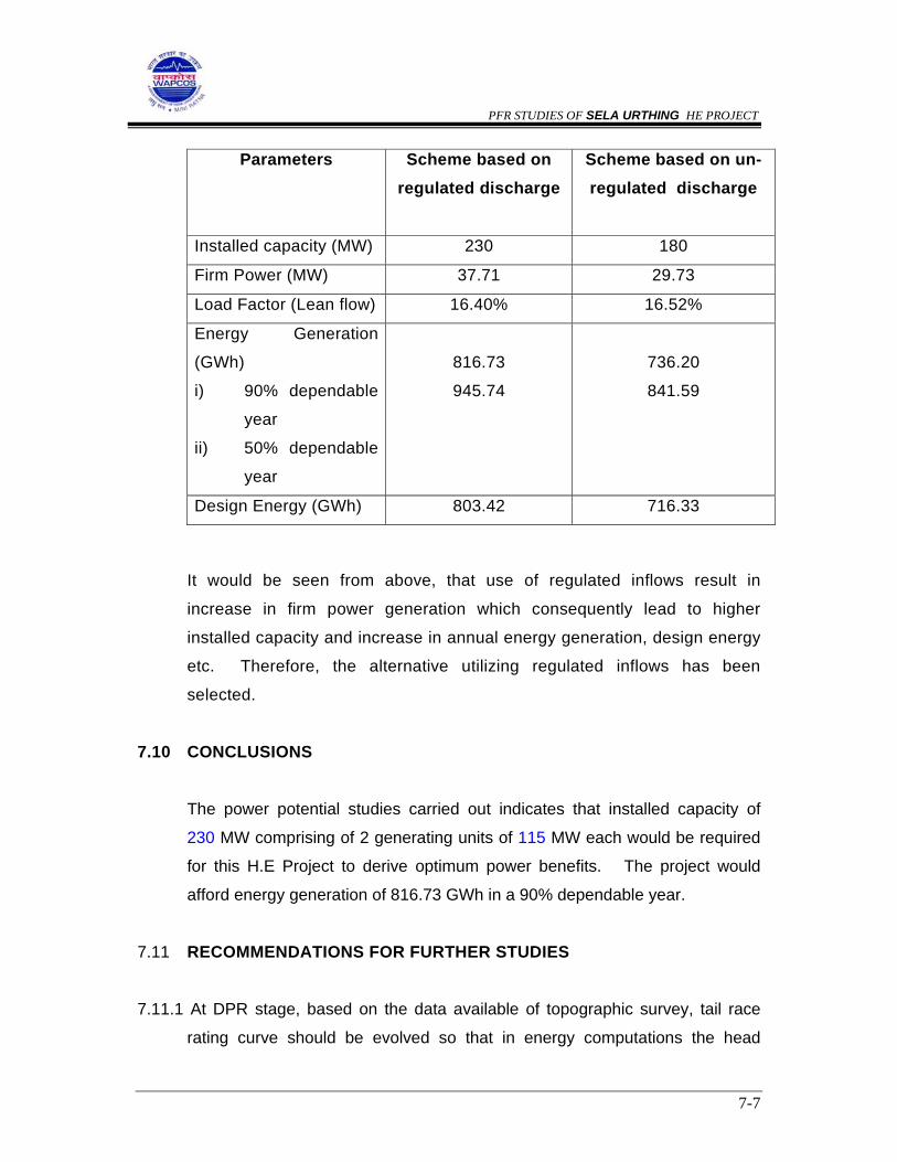
PFR STUDIES OF SELA URTHING HE PROJECT
7-7
Parameters Scheme based on regulated discharge
Scheme based on un-regulated discharge
Installed capacity (MW) 230 180
Firm Power (MW) 37.71 29.73
Load Factor (Lean flow) 16.40% 16.52%
Energy Generation
(GWh)
i) 90% dependable
year
ii) 50% dependable
year
816.73
945.74
736.20
841.59
Design Energy (GWh) 803.42 716.33
It would be seen from above, that use of regulated inflows result in
increase in firm power generation which consequently lead to higher
installed capacity and increase in annual energy generation, design energy
etc. Therefore, the alternative utilizing regulated inflows has been
selected.
7.10 CONCLUSIONS
The power potential studies carried out indicates that installed capacity of
230 MW comprising of 2 generating units of 115 MW each would be required
for this H.E Project to derive optimum power benefits. The project would
afford energy generation of 816.73 GWh in a 90% dependable year.
7.11 RECOMMENDATIONS FOR FURTHER STUDIES
7.11.1 At DPR stage, based on the data available of topographic survey, tail race
rating curve should be evolved so that in energy computations the head
PFR STUDIES OF SELA URTHING HE PROJECT
7-8
utilized for power generation is corrected with the change in tail race level
corresponding to discharge. In the present study, tailrace level was
considered constant.
7.11.2 The storage at FRL and MDDL should be computed with more accuracy
based on the data of topographic survey.
7.11.3 As the benefits from the project gets increased by utilising regulated inflows, it
is recommended that construction of this project should be planned after
implementation of Bokang Bailing H.E Project.
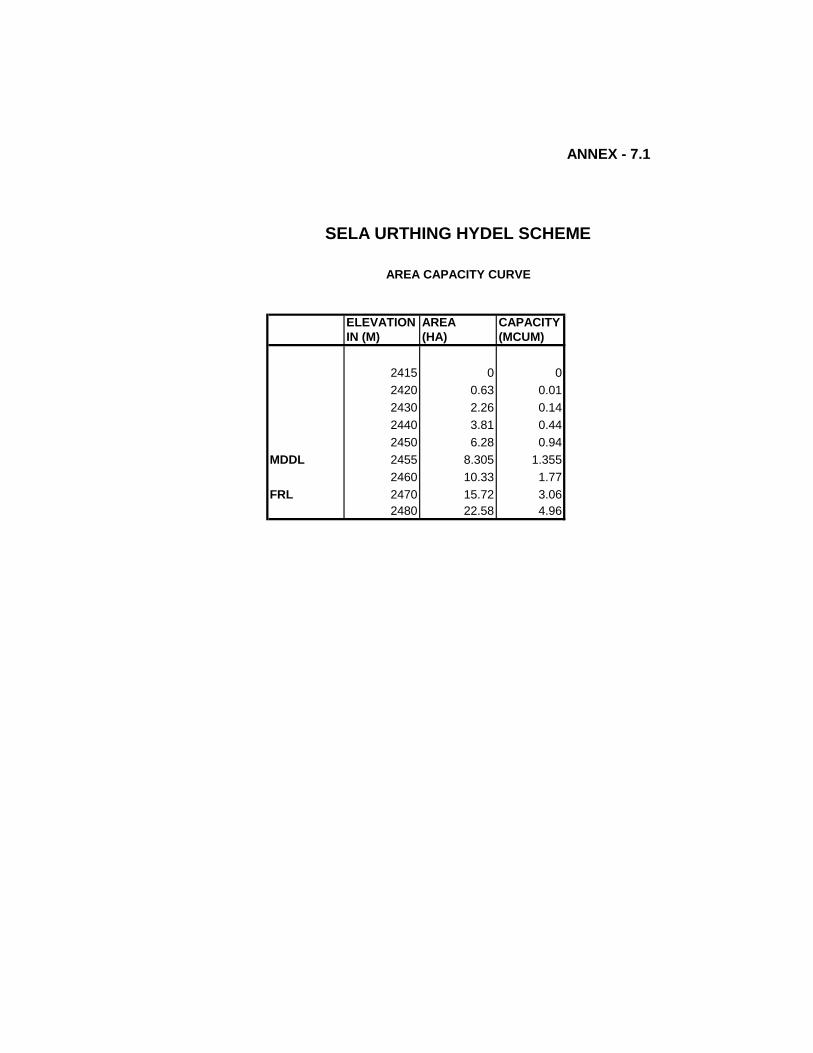
ANNEX - 7.1
AREA CAPACITY CURVE
ELEVATION AREA CAPACITYIN (M) (HA) (MCUM)
2415 0 02420 0.63 0.012430 2.26 0.142440 3.81 0.442450 6.28 0.94
MDDL 2455 8.305 1.3552460 10.33 1.77
FRL 2470 15.72 3.062480 22.58 4.96
SELA URTHING HYDEL SCHEME
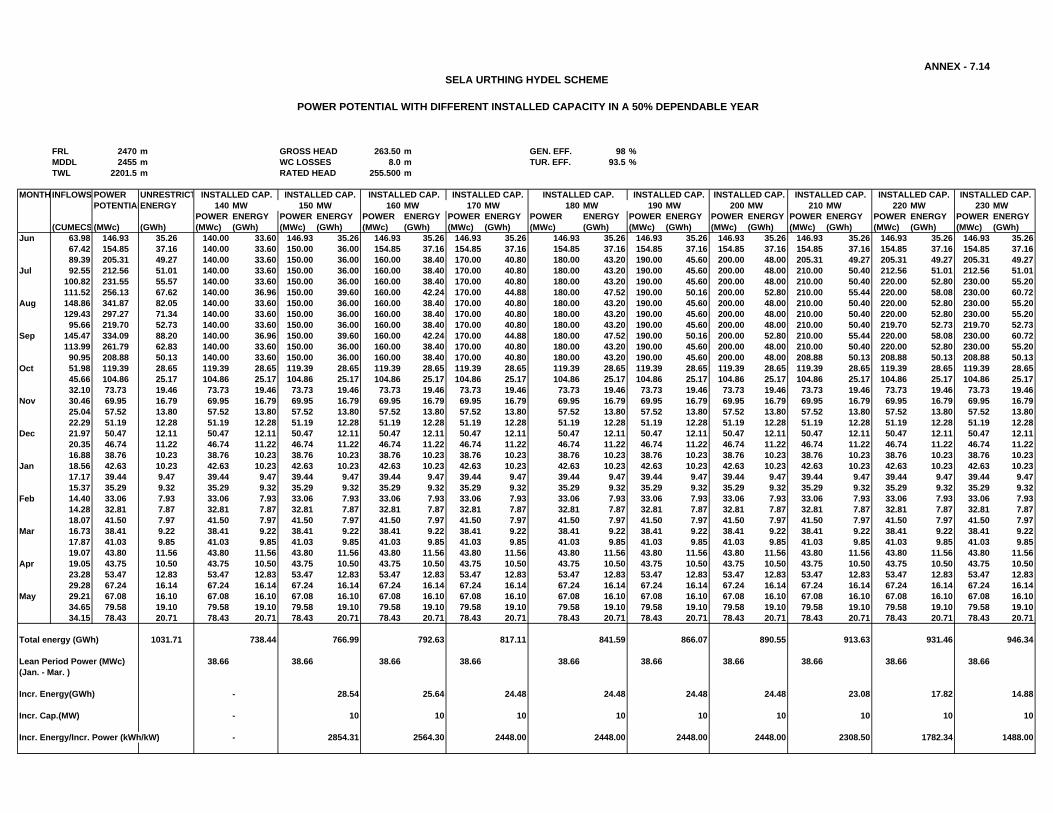
FRL 2470 m GROSS HEAD 263.50 m GEN. EFF. 98 %MDDL 2455 m WC LOSSES 8.0 m TUR. EFF. 93.5 %TWL 2201.5 m RATED HEAD 255.500 m
MONTH INFLOWS POWER UNRESTRICTPOTENTIALENERGY 140 MW 150 MW 160 MW 170 MW 180 MW 190 MW 200 MW 210 MW 220 MW 230 MW
POWER ENERGY POWER ENERGY POWER ENERGY POWER ENERGY POWER ENERGY POWER ENERGY POWER ENERGY POWER ENERGY POWER ENERGY POWER ENERGY(CUMECS (MWc) (GWh) (MWc) (GWh) (MWc) (GWh) (MWc) (GWh) (MWc) (GWh) (MWc) (GWh) (MWc) (GWh) (MWc) (GWh) (MWc) (GWh) (MWc) (GWh) (MWc) (GWh)
Jun 63.98 146.93 35.26 140.00 33.60 146.93 35.26 146.93 35.26 146.93 35.26 146.93 35.26 146.93 35.26 146.93 35.26 146.93 35.26 146.93 35.26 146.93 35.2667.42 154.85 37.16 140.00 33.60 150.00 36.00 154.85 37.16 154.85 37.16 154.85 37.16 154.85 37.16 154.85 37.16 154.85 37.16 154.85 37.16 154.85 37.1689.39 205.31 49.27 140.00 33.60 150.00 36.00 160.00 38.40 170.00 40.80 180.00 43.20 190.00 45.60 200.00 48.00 205.31 49.27 205.31 49.27 205.31 49.27
Jul 92.55 212.56 51.01 140.00 33.60 150.00 36.00 160.00 38.40 170.00 40.80 180.00 43.20 190.00 45.60 200.00 48.00 210.00 50.40 212.56 51.01 212.56 51.01100.82 231.55 55.57 140.00 33.60 150.00 36.00 160.00 38.40 170.00 40.80 180.00 43.20 190.00 45.60 200.00 48.00 210.00 50.40 220.00 52.80 230.00 55.20111.52 256.13 67.62 140.00 36.96 150.00 39.60 160.00 42.24 170.00 44.88 180.00 47.52 190.00 50.16 200.00 52.80 210.00 55.44 220.00 58.08 230.00 60.72
Aug 148.86 341.87 82.05 140.00 33.60 150.00 36.00 160.00 38.40 170.00 40.80 180.00 43.20 190.00 45.60 200.00 48.00 210.00 50.40 220.00 52.80 230.00 55.20129.43 297.27 71.34 140.00 33.60 150.00 36.00 160.00 38.40 170.00 40.80 180.00 43.20 190.00 45.60 200.00 48.00 210.00 50.40 220.00 52.80 230.00 55.2095.66 219.70 52.73 140.00 33.60 150.00 36.00 160.00 38.40 170.00 40.80 180.00 43.20 190.00 45.60 200.00 48.00 210.00 50.40 219.70 52.73 219.70 52.73
Sep 145.47 334.09 88.20 140.00 36.96 150.00 39.60 160.00 42.24 170.00 44.88 180.00 47.52 190.00 50.16 200.00 52.80 210.00 55.44 220.00 58.08 230.00 60.72113.99 261.79 62.83 140.00 33.60 150.00 36.00 160.00 38.40 170.00 40.80 180.00 43.20 190.00 45.60 200.00 48.00 210.00 50.40 220.00 52.80 230.00 55.2090.95 208.88 50.13 140.00 33.60 150.00 36.00 160.00 38.40 170.00 40.80 180.00 43.20 190.00 45.60 200.00 48.00 208.88 50.13 208.88 50.13 208.88 50.13
Oct 51.98 119.39 28.65 119.39 28.65 119.39 28.65 119.39 28.65 119.39 28.65 119.39 28.65 119.39 28.65 119.39 28.65 119.39 28.65 119.39 28.65 119.39 28.6545.66 104.86 25.17 104.86 25.17 104.86 25.17 104.86 25.17 104.86 25.17 104.86 25.17 104.86 25.17 104.86 25.17 104.86 25.17 104.86 25.17 104.86 25.1732.10 73.73 19.46 73.73 19.46 73.73 19.46 73.73 19.46 73.73 19.46 73.73 19.46 73.73 19.46 73.73 19.46 73.73 19.46 73.73 19.46 73.73 19.46
Nov 30.46 69.95 16.79 69.95 16.79 69.95 16.79 69.95 16.79 69.95 16.79 69.95 16.79 69.95 16.79 69.95 16.79 69.95 16.79 69.95 16.79 69.95 16.7925.04 57.52 13.80 57.52 13.80 57.52 13.80 57.52 13.80 57.52 13.80 57.52 13.80 57.52 13.80 57.52 13.80 57.52 13.80 57.52 13.80 57.52 13.8022.29 51.19 12.28 51.19 12.28 51.19 12.28 51.19 12.28 51.19 12.28 51.19 12.28 51.19 12.28 51.19 12.28 51.19 12.28 51.19 12.28 51.19 12.28
Dec 21.97 50.47 12.11 50.47 12.11 50.47 12.11 50.47 12.11 50.47 12.11 50.47 12.11 50.47 12.11 50.47 12.11 50.47 12.11 50.47 12.11 50.47 12.1120.35 46.74 11.22 46.74 11.22 46.74 11.22 46.74 11.22 46.74 11.22 46.74 11.22 46.74 11.22 46.74 11.22 46.74 11.22 46.74 11.22 46.74 11.2216.88 38.76 10.23 38.76 10.23 38.76 10.23 38.76 10.23 38.76 10.23 38.76 10.23 38.76 10.23 38.76 10.23 38.76 10.23 38.76 10.23 38.76 10.23
Jan 18.56 42.63 10.23 42.63 10.23 42.63 10.23 42.63 10.23 42.63 10.23 42.63 10.23 42.63 10.23 42.63 10.23 42.63 10.23 42.63 10.23 42.63 10.2317.17 39.44 9.47 39.44 9.47 39.44 9.47 39.44 9.47 39.44 9.47 39.44 9.47 39.44 9.47 39.44 9.47 39.44 9.47 39.44 9.47 39.44 9.4715.37 35.29 9.32 35.29 9.32 35.29 9.32 35.29 9.32 35.29 9.32 35.29 9.32 35.29 9.32 35.29 9.32 35.29 9.32 35.29 9.32 35.29 9.32
Feb 14.40 33.06 7.93 33.06 7.93 33.06 7.93 33.06 7.93 33.06 7.93 33.06 7.93 33.06 7.93 33.06 7.93 33.06 7.93 33.06 7.93 33.06 7.9314.28 32.81 7.87 32.81 7.87 32.81 7.87 32.81 7.87 32.81 7.87 32.81 7.87 32.81 7.87 32.81 7.87 32.81 7.87 32.81 7.87 32.81 7.8718.07 41.50 7.97 41.50 7.97 41.50 7.97 41.50 7.97 41.50 7.97 41.50 7.97 41.50 7.97 41.50 7.97 41.50 7.97 41.50 7.97 41.50 7.97
Mar 16.73 38.41 9.22 38.41 9.22 38.41 9.22 38.41 9.22 38.41 9.22 38.41 9.22 38.41 9.22 38.41 9.22 38.41 9.22 38.41 9.22 38.41 9.2217.87 41.03 9.85 41.03 9.85 41.03 9.85 41.03 9.85 41.03 9.85 41.03 9.85 41.03 9.85 41.03 9.85 41.03 9.85 41.03 9.85 41.03 9.8519.07 43.80 11.56 43.80 11.56 43.80 11.56 43.80 11.56 43.80 11.56 43.80 11.56 43.80 11.56 43.80 11.56 43.80 11.56 43.80 11.56 43.80 11.56
Apr 19.05 43.75 10.50 43.75 10.50 43.75 10.50 43.75 10.50 43.75 10.50 43.75 10.50 43.75 10.50 43.75 10.50 43.75 10.50 43.75 10.50 43.75 10.5023.28 53.47 12.83 53.47 12.83 53.47 12.83 53.47 12.83 53.47 12.83 53.47 12.83 53.47 12.83 53.47 12.83 53.47 12.83 53.47 12.83 53.47 12.8329.28 67.24 16.14 67.24 16.14 67.24 16.14 67.24 16.14 67.24 16.14 67.24 16.14 67.24 16.14 67.24 16.14 67.24 16.14 67.24 16.14 67.24 16.14
May 29.21 67.08 16.10 67.08 16.10 67.08 16.10 67.08 16.10 67.08 16.10 67.08 16.10 67.08 16.10 67.08 16.10 67.08 16.10 67.08 16.10 67.08 16.1034.65 79.58 19.10 79.58 19.10 79.58 19.10 79.58 19.10 79.58 19.10 79.58 19.10 79.58 19.10 79.58 19.10 79.58 19.10 79.58 19.10 79.58 19.1034.15 78.43 20.71 78.43 20.71 78.43 20.71 78.43 20.71 78.43 20.71 78.43 20.71 78.43 20.71 78.43 20.71 78.43 20.71 78.43 20.71 78.43 20.71
Total energy (GWh) 1031.71 738.44 766.99 792.63 817.11 841.59 866.07 890.55 913.63 931.46 946.34
Lean Period Power (MWc) 38.66 38.66 38.66 38.66 38.66 38.66 38.66 38.66 38.66 38.66(Jan. - Mar. )
Incr. Energy(GWh) - 28.54 25.64 24.48 24.48 24.48 24.48 23.08 17.82 14.88
Incr. Cap.(MW) - 10 10 10 10 10 10 10 10 10
Incr. Energy/Incr. Power (kWh/kW) - 2854.31 2564.30 2448.00 2448.00 2448.00 2448.00 2308.50 1782.34 1488.00
ANNEX - 7.14
INSTALLED CAP. INSTALLED CAP. INSTALLED CAP. INSTALLED CAP. INSTALLED CAP. INSTALLED CAP. INSTALLED CAP.
POWER POTENTIAL WITH DIFFERENT INSTALLED CAPACITY IN A 50% DEPENDABLE YEAR
SELA URTHING HYDEL SCHEME
INSTALLED CAP. INSTALLED CAP. INSTALLED CAP.

PFR STUDIES OF SELA URTHING HE PROJECT
8-1
CHAPTER-VIII
POWER EVACUATION
8.1 APPRAISAL OF EXISTING POWER EVACUATION FACILITIES
The Project is located between latitude 29-30-00 (D-M-S) East to latitude
31-30-00 (D-M-S) East and longitude 78.5o N to 81o N. The installed capacity
of Uttaranchal State is 1286.15 MW as on March 2003. Its peak demand has
been estimated as 771 MW whereas the met peak is 705 MW in the present
scenario. This amounts to deficit of 66 MW (8.56%). Accordingly, energy
requirement is 3774 MU against the available energy of about 3670 MU. This
depicts deficit of 104 MU (2.8%). For the purpose of evacuation of power
pooling has been proposed for various Hydro Electric Power Projects. As per
the geographical locations the following proposed Hydel Projects lie between
the longitude 78.5o N to 79.5o N namely Harsil, Bhaironghati, Gangotri,
Jadhganga, Karmoli Hydro Power Projects. The next group of Hydro Electric
Projects which lie between longitude 79.3o N to 80o N are Badrinath, Gohana
Tal, Rishiganga II, Rishiganga I, Jelum Tamak, Deodi, Devasari Dam and
Malari Jelam. Whereas in the next series the Hydro Electric Projects which lie
between longitude 80o N to 81o N are Mapang Bogudiyar, Sirkari Bhyol
Bogudiyar, Sirkari Bhytol Rus Bagar, Khasiya Bada, Khartoli Lumti Talli,
Kalika Dantu, Garba Tawaghat, Sobala Jhimrigaon, Sela Urthing, Chhanger
Chal, Bokang Beiling. The power map of Uttranchal as on 1/1/2002 is shown
at Annex-8.1.
8.2 PROPOSED EVACUATION SYSTEM TO NEAREST FACILITY
A map has been prepared indicating various proposed Hydro Electric Projects
for the purpose of preparation of prefeasibility report (PFR) indicating their
locations which may be seen at Annex-8.2.

PFR STUDIES OF SELA URTHING HE PROJECT
8-2
8.3 ARRANGEMENT FOR EVACUATION OF POWER FROM SELA URTHING H.E.P
The 230 MW power generated at 11 kV at Sela Urthing H.E.P will be stepped
upto 220 kV by unit step-up-transformers. The power will be taken to newly
proposed 400/220 kV Substation at Didi hat. Proposed line from Sela Urthing
to Didi hat S/S for evacuation of power is shown at Annexure-8.3.
8.4 ROUTE LENGTH AND COSTING OF 220 KV D/C TRANSMISSION LINE
FOR EVACUATION OF POWER FROM SELA URTHING H.E.P
The power of this project is intended to be evacuated by proposed 220 kV
D/C line to newly proposed 400/220 kV substation at Didi hat. The total
length of this line would be around 45 km upto Didi hat. The cost of this
portion of line is estimated as Rs.33.75 crores.

PFR STUDIES OF SELA URTHING HE PROJECT
9-1
CHAPTER – IX
INITIAL ENVIRONMENTAL EXAMINATION STUDIES
9.1 INTRODUCTION
The Initial Environmental Examination of Sela Urthing hydroelectric project
has following objectives which are proposed to be covered through various
phases of development:
• provide information on baseline environmental setting;
• preliminary assessment of impacts likely to accrue during construction
and operation phases;
• identify key issues which need to be studied in detail during
subsequent environmental studies
It is essential to ascertain the baseline status of relevant environmental
parameters that could undergo significant changes as a result of construction
and operation of the project. In an Initial Environmental Examination (IEE)
study, baseline status is ascertained through review of secondary data,
reconnaissance survey and interaction with the locals.
The Preliminary Impact Assessment conducted as a part of IEE study, is
essentially a process to forecast the future environmental scenario of the
project area that might be expected to occur as a result of construction and
operation of the proposed project. The key environmental impacts which are
likely to accrue as a result of the proposed developmental activity are
identified. Various impacts, which can endanger the environmental
sustainability of a project, are highlighted for comprehensive assessment as a
part of next level of environmental study during detailed studies.

PFR STUDIES OF SELA URTHING HE PROJECT
9-2
9.2 ENVIRONMENTAL BASELINE SETTING
The study area covered includes the area within 7 km radius of various project
appurtenances. The data was collected through review of existing documents
and various engineering reports and reconnaissance surveys.
The various parameters for which baseline setting has been described have
been classified into physio-chemical, ecological and socio-economic aspects.
9.2.1 Physio-Chemical Aspects
a) Water Quality
The proposed project is located in an area, with low population density.
There are no major sources of water pollution in the area and therefore
water quality of diver Dhauliganga in this area is excellent. The present
population in the catchment area intercepted at the dam site is of the
order of 4,000. The major source of water in the project area rivers or
nallahs which flow adjacent to the habitations, which are conveyed to
the consumers under gravity. The sewage so generated, too outfalls
into various streams or nallahs flowing adjacent to the settlements. The
total BOD load from domestic sources in the catchment area
intercepted at the dam site is of the order of 180 kg/day. The effluent
ultimately reaches river Dhauli Ganga through various
streams/channels outfalling into the river. River Dhauli Ganga is a
perennial river, with significant flows throughout the year. Likewise, use
of agro-chemicals is negligible in the catchment area. Thus, pollution
from various sources is virtually absent in the catchment intercepted at
the diversion structure site. Thus, in absence of pollution sources, river
water quality is quite good in the area, with high DO and low BOD
levels. The TDS level is well within the permissible limit. As a result, the
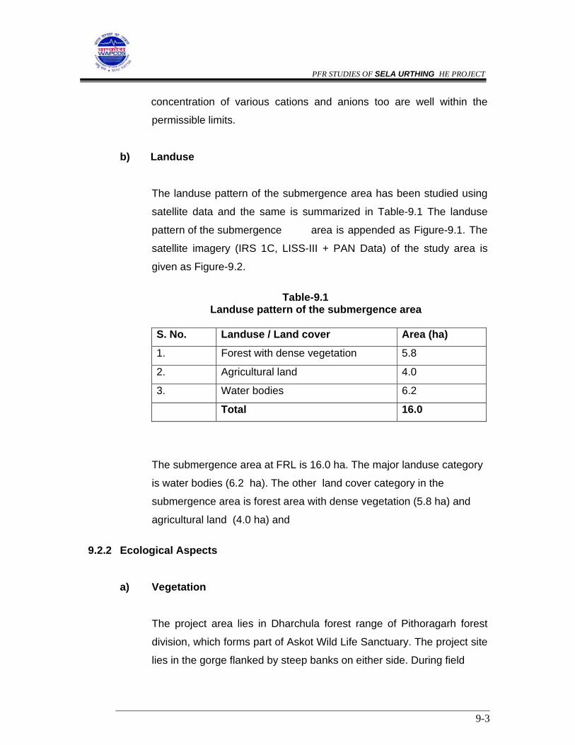
PFR STUDIES OF SELA URTHING HE PROJECT
9-3
concentration of various cations and anions too are well within the
permissible limits.
b) Landuse
The landuse pattern of the submergence area has been studied using
satellite data and the same is summarized in Table-9.1 The landuse
pattern of the submergence area is appended as Figure-9.1. The
satellite imagery (IRS 1C, LISS-III + PAN Data) of the study area is
given as Figure-9.2.
Table-9.1
Landuse pattern of the submergence area
S. No. Landuse / Land cover Area (ha)
1. Forest with dense vegetation 5.8
2. Agricultural land 4.0
3. Water bodies 6.2
Total 16.0
The submergence area at FRL is 16.0 ha. The major landuse category
is water bodies (6.2 ha). The other land cover category in the
submergence area is forest area with dense vegetation (5.8 ha) and
agricultural land (4.0 ha) and
9.2.2 Ecological Aspects
a) Vegetation
The project area lies in Dharchula forest range of Pithoragarh forest
division, which forms part of Askot Wild Life Sanctuary. The project site
lies in the gorge flanked by steep banks on either side. During field

PFR STUDIES OF SELA URTHING HE PROJECT
9-4
investigations, mixed vegetation consisting mainly of Ringal
(Arundinaria sp.), Tansen (Tsuga demosa), Tuner (Taxus bacata) was
observed in the project area. Due to the high altitude and cold climate
agriculture is not being practised in this area.
Catchment area of the proposed project extends upto the snowline
therefore floral species are mainly restricted up to the hill slopes. Top
of the hills is generally barren and most part of the hills is under snow.
The hill slopes in the area generally represent open forests except few
patches of dense forest.
Vegetation on hills in the upper reaches in the area comprises mainly
of Bhojpatra (Betula utilis), Thuner (Taxus bacata), Tansen (Tsuga
demosa) and Chir (Pinus roxburghii) tree species. In addition, various
shrubs species were also observed in the project area and its
surroundings. The dominant species of shrubs observed in
the area are Ghingaru (Pysectantha crenulatu), Hinsalu (Rubus
ellipticus), Kilmora (Berberis asiatica), etc. The power house is
proposed to be located about 3 km downstream of Sela, near village
Urthing. On the left bank near power house, slopes covered with grass
interspersed with patches of open forests are observed. Right bank of
Dhauli Ganga near power house site has reasonably good forest on
the slopes. Major tree species observed in this area includes Pangar,
Utees, Ringal and Kharsu etc. The hill top in area as observed around
the diversion structure site. Small patches of terrace agriculture were
also noticed near power house.
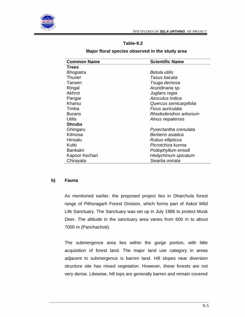
PFR STUDIES OF SELA URTHING HE PROJECT
9-5
Table-9.2 Major floral species observed in the study area
Common Name Scientific Name Trees Bhojpatra Betula utilis Thuner Taxus bacata Tansen Tsuga demosa Ringal Arundinaria sp. Akhrot Juglans regia Pangar Aesculus indica Kharsu Quercus semicarpifolia Timba Ficus auriculata Burans Rhododendron arborium Utilis Alnus nepalensis Shrubs Ghingaru Pysectantha crenulata Kilmosa Berberis asiatica Hinsalu Rubus ellipticus Kutki Picrotchiza kurroa Bankakri Podophyllum emodi Kapoor Kechari Hedychinum spicatum Chirayata Swartia onirata
b) Fauna
As mentioned earlier, the proposed project lies in Dharchula forest
range of Pithoragarh Forest Division, which forms part of Askot Wild
Life Sanctuary. The Sanctuary was set up in July 1986 to protect Musk
Deer. The altitude in the sanctuary area varies from 600 m to about
7000 m (Panchachoti).
The submergence area lies within the gorge portion, with little
acquisition of forest land. The major land use category in areas
adjacent to submergence is barren land. Hill slopes near diversion
structure site has mixed vegetation. However, these forests are not
very dense. Likewise, hill tops are generally barren and remain covered

PFR STUDIES OF SELA URTHING HE PROJECT
9-6
with snow for most part of the year. Thus, no major faunal species are
reported in the submergence area and its surroundings.
Based on the review of secondary data and interaction with the Forest
Department, major faunal species observed in the study area include
Langur, Goral, Bagh, Wild goat, Black bear, etc. Amongst the reptiles,
lizard was the dominant species observed in the project area. Amongst
the avi-fauna, the commonly reported species were Jungle Crow, Kala
Titar, etc.
The faunal species observed in the study area including project area is
outlined in Table-9.3.
Table-9.3 List of faunal species observed in the study area including project area
___________________________________________________________________ Local Name Scientific Name Schedule as per Wildlife Act ____________________________________________________________________ Mammals Goral Nemarhaedus goral Barking deer Muntiacus muntjak Schedule-I Black Bear Selenactos thibetanus Langur Presbytis entellus Schedule-I Snow Leopard Panthera Schedule-I Reptiles Lizard Hemidactyles brooki Monitor lizard Varanus bengalensis Avi-fauna Hill patridge Arbosophila torquota Koklas Puerassia macrolophus Pigeon Columba livia Crow Corvus macrorhnchas Chakor Alectoria gracia Kala Titar Francolinus francolinus ___________________________________________________________________
PFR STUDIES OF SELA URTHING HE PROJECT
9-7
It is observed that few species were categorised as Schedule-I as per
Wildlife Protection Act (1972). Such species are akin to rare and
endangered species. As a part of EIA study data collection needs to be
done to ascertain the impacts on such species in detail to ascertain
impacts on them as a result of the proposed project.
c) Fisheries
The proposed project lies on river Dhauliganga which is a tributary of
river Kali. During interaction with the locals and Fisheries Department,
it was confirmed that no major data on fisheries is available of
Dhauliganga. The river Dhauliganga is glacial origin, as a result water
temperature is quite low. The substrata in the river in upper reaches
contain either boulder stone mixed with pebbles, gravel and sand while
at lower reaches it is mixed with sand. The low water temperature
leads to low biological productivity. As a result, small size fishes are
available in this river and its tributary. The main fish species observed
Mahseer (Tor tor and Tor putitora) and Snow trout (Schizothorax
plageostomas) Both snow trout and Mahaseer are migratory species.
Snow trout is endemic to Himalayas and is known to occur in almost all
streams and rivers of Pithoragarh upto an elevation of 2000 m. River
Dhauli and its tributaries have poor catch in the upper reaches. In
winter months when the water temperature touches almost 0oC, snow
trout migrates in the downstream area .
Mahseer are one of the finest group of sport fishes which during spring
and summer months are reporter to migrate upstream. During winter
month when temperature goes down these migrate in the downstream
and reported only near its confluence with river Kali.

PFR STUDIES OF SELA URTHING HE PROJECT
9-8
It is recommended that a detailed fisheries fishery survey be
conducted in river Dhauli as a part of EIA study to ascertain the spatio-
temporal occurrence of Mahaseer and snow trout.
9.2.3 Socio-economic aspects
It is imperative to study socio-economic characteristics including demographic
profile of the project area and the study area. The proposed project lies in
tehsil Dharchula of district Pitoragarh. A total of 9 villages are observed total 9
villages in the study area of the proposed project.
The demographic profile of the study area villages is given in Table-9.4.
Table-9.4 Demographic profile of study area villages
S. No
Village No. of households
Population SC ST Literates
Male Female Total Male Female
1. Umachiya 60 157 158 315 3 11 93 44
2 Tejam 36 99 54 153 30 62 49 7
3. New 62 178 118 296 33 108 87 21
4. Dar 102 244 244 488 34 216 111 30
5. Bauling 29 58 71 129 25 103 25 8
6. Nagling 40 101 78 179 53 105 50 17
7. Sela 26 54 50 104 18 86 21 7
8. Chal 28 63 42 105 13 91 30 2
9. Baling 34 70 64 134 6 127 46 12
Total 417 1024 875 1903 215 909 512 148
Source : Census data 1991
The average family size in the study area is about 4.5, with a total population
of 1903. The sex ratio i.e. number of females per 1000 males is 854. The SC

PFR STUDIES OF SELA URTHING HE PROJECT
9-9
and ST population accounts for 11% is 48% of the total population. The
literacy rate in the study area is low, i.e. of the order of 35%. The male and
female literacy rates are 50% and 16.9% respectively.
9.3 PREDICTION OF IMPACTS
Based on the project details and the baseline environmental status, potential
impacts as a result of the construction and operation of the proposed project
have been identified.
As a part of IEE study, impacts on various aspects listed as below have been
assessed:
- Land environment - Water resources - Water quality - Terrestrial flora - Terrestrial fauna - Aquatic ecology - Noise environment - Ambient air quality - Socio-economic environment
9.3.1 Impacts on Land Environment a) Construction phase
Quarrying operations
A hydroelectric project requires significant amount of construction material,
which needs to be extracted from various quarry sites in and around the
project area. Normally quarrying is done along the hill face, and generally left
untreated after extraction of the required construction material. These sites

PFR STUDIES OF SELA URTHING HE PROJECT
9-10
can become permanent scar on the hill face and can become potential source
of landslides.
This aspect needs to be covered as a part of the EIA study and suitable
measures for stabilization of quarry sites need to be recommended. It is
recommended that existing operational quarries be utilised for extraction of
construction material. However, if new quarries have to be opened,
then the same be located in non forest land and preferably away from human
settlements, so that adverse impact minimized to the extent possible.
Operation of construction equipment
During construction phase, various equipment will be brought to the site.
These include crushers, batching plant, drillers, earth movers, rock bolters,
etc. The siting of these construction equipment would require significant
amount of space. Similarly, space will be required for workshop, storing of
other construction equipment and materials, etc. In addition, land will also be
temporarily acquired, for storage of the quarried material before crushing,
rubble, sand crushed material, cement, spare parts yard, fuel storage, guard
room, parking of light and heav vehicles, petrol & diesel pumps, temporary
& permanent residential colonies for government and contractor’s labour,
water supply and switch yard for onstruction purposes, etc. Various storage
sites need to be earmarked for this purpose. It is recommended that to the
extent possible, such sites be located over non-forest land outside the
sanctuary area. Village Mangti is located quite close to the dam site, likewise
village Tawaghat is located close to the power house site. It is suggested that
project layout is planned in a way that there is minimal disturbance to human
population in the above referred nearby villages.
PFR STUDIES OF SELA URTHING HE PROJECT
9-11
Problems of muck disposal
A large quantity of muck is expected to be generated as a result of tunneling
operations, construction of access roads, etc. The muck so generated needs
to be properly disposed otherwise it can lead to significant adverse impacts on
environment. Normally muck is disposed along the river bank which ultimately
finds it way into the water body, leading to adverse impacts on riverine
ecology and also disrupts hydraulic regime.
It is proposed that muck be disposed over low lying areas, with minimum
vegetal cover and preferably over non-forest land outside the sanctuary area.
Muck has low nutrients, hence, natural vegetal growth is unlikely at
muck disposal sites, as a result of which specific bio-engineering measures
need to be implemented.
Specific site-specific management measures can be suggested as a part of
EIA study.
Construction of roads
The topography of the project area has steep to precipitous slopes which
descends rapidly into narrow valleys. Significant vehicular movement for
transportation of large construction material, heavy construction equipment is
anticipated during construction phase. Many new roads shall be constructed
as a part of project. Construction of new roads may lead to removal of trees
on slopes and re-working of the slopes in the immediate vicinity of road, which
may lead to landslides, soil erosion, gully formation, etc. Adequate
management measures need to be implemented to ameliorate such impacts.

PFR STUDIES OF SELA URTHING HE PROJECT
9-12
b) Operation Phase
The area coming under reservoir submergence is 16 ha About 5.8 ha
of forest land is to be acquired. About 4.0 ha of agriculture land under
terrace cultivation would come under reservoir submergence. In
addition to above, an area of 50-55 ha will be required for siting of
various project appurtenances, infrastructure, etc. It is recommended
that to the extent possible, such sites be located over non-forest land
outside the periphery of Askot Wildlife sanctuary. The ownership
category of land required for various project appurtenances can be
ascertained, once project layout is finalized as a part of DPR
preparation.
9.3.2 Impacts on Water Resources
The construction of dam as a part of the proposed project diversion of
discharge for hydropower generation would lead to reduction in flow for a river
stretch downstream of the dam site up to the confluence point of tail race
discharge. Within the affected river stretch, there are few settlements, which
do not use water from river Dhauli Ganga for meeting their water
requirements. Thus, reduction in flow during lean season is unlikely to lead to
any significant impact.
However, reduction in flow is likely to have a minor impact on riverine ecology,
though the discharge during lean flow is significantly less, but the intervening
nallahs and streams do supplement the minimum flow in the stretch under
study.

PFR STUDIES OF SELA URTHING HE PROJECT
9-13
9.3.3 Impacts on Water Quality
a) Construction phase
The project construction is likely to last for a period of 5 years apart
from investigation stage. About 2000 workers and 500 technical staff
are likely to work during project construction phase. The construction
phase, also leads to mushrooming of various allied activities to meet
the demands of the immigrant labour population in the project area.
Thus, the total increase in labour population during construction phase
is expected to be around 5000-6000. The total quantum of sewage
generated is expected to be of the order of 0.4 mld. The BOD load
contributed by domestic sources will be about 270 kg/day. The sewage
generally shall be disposed in nearby streams or channels through
open drains, where ultimately it will find its way into river Dhauliganga.
The inadequate sewage treatment and disposal facilities could lead to
increased incidence of water-related diseases. Thus, it is
recommended to commission adequate sewage treatment facilities in
the labour camps.
Normally, during construction phase, elaborate sewage treatment
facilities including primary and secondary treatment units are not
commissioned, as they remain unutilized, once the construction phase
is over. At such sites, septic tanks or other low cost sanitation units are
developed. Similar sewage treatment measures are envisaged in the
labour camps of the proposed project as well. Since, the proposed
project lies in Askot Wildlife sanctuary, hence, it is recommended that
the labour camp be located outside the sanctuary area.
PFR STUDIES OF SELA URTHING HE PROJECT
9-14
b) Operation phase
Effluent from project colony
In the operation phase, about 150 families will be residing in the area
which would generate about 0.9 mld of sewage. The quantum of
sewage generated is not expected to cause any significant adverse
impact on riverine water quality. Adequate sewage treatment facilities
including secondary treatment facilities need to be commissioned for
this purpose to ameliorate the marginal impacts. It is recommended
that the project colony be located outside the sanctuary area.
Impacts on reservoir water quality
The flooding of forest and agricultural land in the submergence area
increases the availability of nutrients resulting from decomposition of
vegetative matter. Enrichment of impounded water with organic and
inorganic nutrients at times become a major water quality problem
immediately on commencement of the operation and is likely to
continue in the initial years of operation.
The reservoir in the proposed diversion structure site could entail
submergence of forest and agricultural lands. Thus, it is recommended
that a detailed DO modelling study be conducted as a part of the EIA
study to assess the impacts on reservoir water quality.
Eutrophication risks
The fertilizer use in the catchment area intercepted at the diversion
structure site is negligible and is unlikely to change even during project
operation phase. Since, the present proposal envisages only
hydropower generation and does not entail command area

PFR STUDIES OF SELA URTHING HE PROJECT
9-15
development, problems of eutrophication, which are primarily caused
by enrichment of nutrients in water are not anticipated.
9.3.4 Impacts on Terrestrial Flora
a) Construction phase
Increased human interferences
As mentioned earlier, about 2,500 technical staff, workers and other
group of people are likely to congregate in the area during the project
construction phase. The total increase in population is expected to be
about 5000-6000. Workers and other population groups residing in the
area may use fuel wood, if no alternate fuel is provided. On an
average, the fuel wood requirements will be of the order of 2500-2700
m3. Thus, every year, fuel wood equivalent to about 800-900 trees will
be cut, which implies that every year on an average about 1 ha of
dense forest area will be cleared for meeting fuel wood requirements, if
no alternate sources of fuel are provided. Since, the project lies in
sanctuary area, it should be made mandatory for the contractor
involved in project construction to provide alternate source of fuel to the
labour population. Alternatively, community kitchen using LPG or
kerosene as a fuel can also be run at various labour camps.
b) Operation Phase
Acquisition of forest land
The total submergence area at FRL is 16.0 ha. The forest land to be
acquired is 5.8 ha. In addition, about 50-55 ha of land will also be
required for siting of construction equipment, storage of construction
material, muck disposal, widening of existing roads, construction of

PFR STUDIES OF SELA URTHING HE PROJECT
9-16
new project roads, infrastructure development. Efforts need to be made
to ensure that there is minimal acquisition of forest land for meeting the
above land requirements. It is recommended that a
detailed ecological survey be conducted as a part of EIA study to
assess the density and diversity of flora in the area to be acquired for
various project appurtenances. Species requiring conservation
need to be identified and if required the conservation plan for the same
be prepared.
9.3.5 Impacts on Terrestrial Fauna
a) Construction phase
The forest area, in the study area provides habitat to various faunal
species, quite a few which are classified under Schedule-I category as
per the Wildlife Protection Act (1972). As a part of the EIA study,
detailed data collection from various secondary sources needs to be
done to assess the severity of impacts due to various activities in the
construction and operation phases on Schedule-I and other faunal
species.
b) Operation phase
Impacts due to increased human interferences
During project operation phase, accessibility to the area will improve
due to construction of roads, which in turn may increase human
interference leading to marginal adverse impacts on the terrestrial
ecosystem. Since, the increase in human population is not expected to
be large, hence significant adverse impacts on this account are not
anticipated.
PFR STUDIES OF SELA URTHING HE PROJECT
9-17
Impacts on wildlife movement
Perusal of various faunal species observed in the project area,
indicates that there are no migratory faunal species observed in the
area. River Dhauli Ganga in the project area, even in the pre-project
phase, acts as a barrier to wildlife movement. Thus, construction of a
small reservoir as a part of the proposed project is not expected to
cause any additional barrier to wildlife movement in the project area.
9.3.6 Impacts on Aquatic Ecology
a) Construction phase
During construction of a river valley project, huge quantity of muck is
generated at various construction sites, which if not properly disposed,
invariably would flow down the river during heavy precipitation. Such
condition can lead to adverse impacts on the development of aquatic
life, which needs to be avoided.
The increased labour population during construction phase, could lead
to increased pressure on fish fauna, as a result of indiscriminate fishing
by them. Adequate protection measures at sensitive locations,
identified on the basis of fisheries survey in the EIA study need to be
implemented.
b) Operation phase
Amongst the aquatic fauna, it is the fish life which would be most
affected. The migratory fish species, e.g. snow trout and Mahaseer are
likely to be adversely affected due to obstruction to their migratory
route created by the proposed diversion structure. The dispersal and
migration pattern of various fish species needs to be ascertained to
PFR STUDIES OF SELA URTHING HE PROJECT
9-18
assess the degree of severity of impacts, which needs to be done as a
part of EIA study.
9.3.7 Impacts on Noise Environment
Increased noise levels are anticipated only during construction phase due to
operation of various equipment, increased vehicular traffic and blasting, etc.
Village Chal is located at about 3 km from the diversion structure site. The
increased noise level will not have any impacts on the residents of village
Sela. However, increased noise level, especially blasting could scare away
wildlife from forest of the area. It has been observed during construction
phase of similar projects, that wildlife migrates from such areas and returns
after the cessation of construction activities. Similar phenomenon is expected
in the proposed project site as well. Since, the propsed project lies in
Askot Wildlife Sanctuary, it is recommended to conduct detailed noise
modelling studies as a part of EIA study.
Based on the increased noise levels, as estimated through modelling studies,
impacts on human and wildlife in areas adjacent to the project site can be
assessed.
9.3.8 Air Pollution
Pollution due to fuel combustion in various equipment
Normally, diesel is used in construction equipment. The major pollutant which
gets emitted as a result of diesel combustion is SO2. The SPM emissions are
minimal due to low ash content in diesel. Model studies conducted for various
projects with similar level of fuel consumption indicate that the short-term
increase in SO2, even assuming that all the equipment are operating at a
common point, is quite low, i.e. of the order of less than 1μg/m3. Hence, no
major impact is anticipated on this account.

PFR STUDIES OF SELA URTHING HE PROJECT
9-19
Emissions from various crushers
The operation of the crusher during the construction phase is likely to
generate fugitive emissions, which can move even up to 1 km along the
predominant wind direction. During construction phase, one crusher each is
likely to be commissioned at the diversion structure site and the power house
site. During crushing operations, fugitive emissions comprising of the
suspended particulate will be generated. Since, village Sela is located about 3
km from the diversion structure site, no impact on ambient air quality is
anticipated. It is recommended that a detailed ambient air quality modelling
study be conducted to assess the increase in SPM level at village Sela due to
operation of various crushers. It is also recommended that the labour camp be
situated at least 1 km away from the construction sites and that too on the
leeward side of the pre-dominant wind direction in the area.
9.3.9 Impacts on Socio-Economic Environment
a) Construction phase
The construction phase will last for about 5 years. Those who would
migrate to this area are likely to come from various parts of the country
mainly having different cultural, ethnic and social backgrounds. Due to
longer residence of this population in one place, a new culture, having
a distinct socio-economic
similarity would develop which will have its own entity. It is
recommended that labour camps/colonies be located over non-forest
area outside the sanctuary area. Normaly during construction phase of
a project, there is significant impact on the employment potential of the
area.

PFR STUDIES OF SELA URTHING HE PROJECT
9-20
b) Project operation phase
The commissioning of a hydro-electric project provides significant
impetus to economic development in the area being supplied with
power. Likewise, in the project area, commissioning of a hydro-electric
project would lead to mushrooming of various allied activities, providing
employment to locals in the area. About 4.0 ha of agriculture land
under terrace cultivation in village Mangti would come under reservoir
submergence. In addition about 50-55 ha of land also needs to be
acquired for various project appurtenances. As a part of EIA study,
data on ownership status of land to be acquired for various project
appurtenances, needs to be collected to ascertain loss of private land
and homestead, if any. If required, a suitable Resettlement &
Rehabilitation Plan can be prepared.
9.4 SUMMARY OF IMPACTS AND EMP
A summary of impacts and recommended management measures are
summarized in Table-9.5.
Table-9.4
Summary of Impacts and suggested management measures
S. No
Parameters Impact Management Measures
1. Land Environment
Construction phase
• Soil erosion due to the
extraction of
construction material
from various quarry
sites.
• Temporary acquisition
• Proper treatment of
quarry site, and such
sites be located over
non-forest land, outside
the periphery of Askot
Wildlife sanctuary.
• Such sites be located
PFR STUDIES OF SELA URTHING HE PROJECT
9-21
Operation phase
of land for siting of
construction equipment
& material, waste
material, etc.
• Generation of muck due
to tunnelling operations
& roads.
• Acquisition of various
categories of land.
over non-forest land,
outside the periphery of
Askot Wildlife
sanctuary.
• Disposal at designated
sites and provision of
suitable management
measures including bio-
engineering treatment
measures and location
of such sites over non-
forest land outside the
periphery of Askot
Wildlife sanctuary.
• Compensatory
measures to be
formulated based on
the type of land to
acquired.
2. Water resources
Operation phase
• River stretch from
diversion structure site
to tail race outfall will
have reduced flow
especially during lean
season.
• In case downstream
nallahs do not
contribute lean flows
minimum flow will be
released to maintain the
riverine ecology.
3. Water quality

PFR STUDIES OF SELA URTHING HE PROJECT
9-22
Construction phase Operation phase
• Water pollution due to
disposal of sewage
from labour colonies.
• Disposal of sewage
from project colony.
• Provision of community
toilets and septic tanks
• Provision of adequate
sewage treatment
facilities
4. Terrestrial flora
Construction phase Operation phase
• Cutting of trees for
meeting fuel wood
requirements by labour.
• Acquisition of 5.8 ha of
area in wildlife
sanctuary.
• Provision of community
kitchen by the
contractors engaged in
project construction.
• Compensatory
afforestation and other
measures as per the
Indian Forest
Conservation Act
(1980)
5. Terrestrial fauna
Construction phase Operation phase
• Disturbance to wildlife
due to operation of
various construction
equipment.
• Disturbance to wildlife
due to increased
accessibility in the area.
• Increased surveillance,
in the form of check
posts at major
construction sites and
labour camps.
• Specific management
measures are not
required
6. Aquatic Ecology
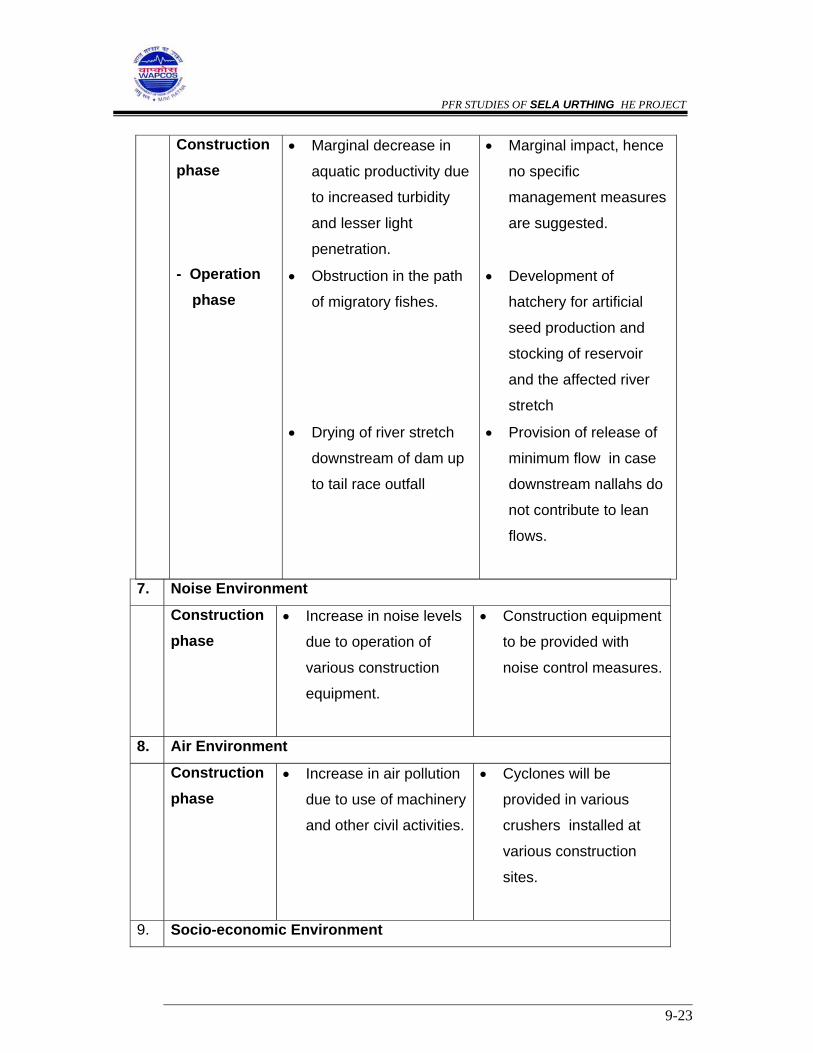
PFR STUDIES OF SELA URTHING HE PROJECT
9-23
Construction phase - Operation
phase
• Marginal decrease in
aquatic productivity due
to increased turbidity
and lesser light
penetration.
• Obstruction in the path
of migratory fishes.
• Drying of river stretch
downstream of dam up
to tail race outfall
• Marginal impact, hence
no specific
management measures
are suggested.
• Development of
hatchery for artificial
seed production and
stocking of reservoir
and the affected river
stretch
• Provision of release of
minimum flow in case
downstream nallahs do
not contribute to lean
flows.
7. Noise Environment
Construction phase
• Increase in noise levels
due to operation of
various construction
equipment.
• Construction equipment
to be provided with
noise control measures.
8. Air Environment
Construction phase
• Increase in air pollution
due to use of machinery
and other civil activities.
• Cyclones will be
provided in various
crushers installed at
various construction
sites.
9. Socio-economic Environment

PFR STUDIES OF SELA URTHING HE PROJECT
9-24
Construction phase -Operation phase
• Increase in employment
potential.
• Increased power
generation
• Greater employment
opportunities.
• Acquisition of 4.0 ha of
agricultural land.
-
-
• Implementation of R&R
plan and Area
Development Activities
9.5 CONCLUSIONS AND RECOMMENDATIONS
The proposed project lies in Dharchula forest range of Pithoragarh Forest
Division, which forms part of Askot Wild Life Sanctuary. The environmental
clearance would require approval from Wildlife Board as well. Therefore, it is
proposed that a detailed ecological survey be conducted as a part of EIA
study for this project to ascertain the ecological status of this area. The
following aspects need to be studied in detail as a part of next phase of
environmental studies:
- Impacts due to acquisition of land in Askot Wildlife Sanctuary.
- Impacts on wildlife, especially species categorized as Schedule-I
species as per Wildlife Protection Act (1972).
- Impediment to migratory fish species as a result of construction of dam.
- Proper stabilization of quarry and muck disposal sites
- Management of pollution from various sources from labour camps

PFR STUDIES OF SELA URTHING HE PROJECT
10-1
CHAPTER - X
INFRASTRUCTURE FACILITIES
10.1 GENERAL
The Sela Urthing hydroelectric project across the river Dhauliganga envisages
construction of a dam about 73 m high from the deepest foundation, a 2.01
m long HRT, an underground desilting basin, penstocks and a surface power
house with an installed capacity of 230 M.W. (2 x 115 MW) and a tail race
channel. The dam site is located at about 450 m downstream of Sela village.
The power house is on the right bank of Dhauliganga downstream of
confluence of Misling Gad and Syanar Ki Dhar on left and right bank
respectively with Dhauliganga river. The major infrastructure facilities needed
are described in the following paragraphs.
10.2 COMMUNICATIONS
10.2.1 The nearest rail head available to the project is Tanakpur (M.G.) which is
about 283 km from the dam site.
From Tanakpur up to Khela via Champawat, Pithoragarh and Dharchula, a
wide black topped road exists after which the approach to the proposed
project site is through kuchha road/trekking paths. The total distance from
Khela to dam site is about 20 km.
10.2.2 Roads in the Project Area
For project construction, the road from Dharchula to Khela needs
improvement at places. Fresh roads needs to be built, by improving the
existing kuchha road / tracks from Khela to dam site. Existing bridges/culverts

PFR STUDIES OF SELA URTHING HE PROJECT
10-2
across various nallahs along the route to Dam & PH site need to be
strengthened / widened for use during and after construction.
Construction roads are also required from dam / power house site to quarry
sites, and plant and machinery workshops etc.
Considering the existing road facilities, lengths of new roads to be
constructed for this project will be about 20 km.
10.2.3 Railways
The nearest railway stations are Tanakpur (Metre Gauge) and Kathgodam on
the Broad Gauge line. Railway siding for unloading heavy machineries and
equipment is to be provided at the station selected.
10.3 CONSTRUCTION POWER
The power demand for the construction activities is estimated to be about 4
M.W. taking into consideration capacity of lighting and electric driven
equipment which are to work within the target time.
The power requirement can be met with by procuring the supply from
Uttaranchal state electricity authorities. For making the power available at
project site 33/11 K.V. substation alongwith new power lines will be required.
In addition to tapping grid supply, it is also proposed to provide supplemental
power aggregating to 2 M.W. from diesel generating sets, as a stand by in
cases of interruptions in grid supply.

PFR STUDIES OF SELA URTHING HE PROJECT
10-3
10.4 TELECOMMUNICATION
To ensure efficient execution at various sites, adequate and reliable
telecommunication network is necessary. An electronic automatic exchange
with a capacity of about 50 lines is proposed.
A VHF system is also proposed to link project Head Quarters with clients
head-quarters.
Suitable number of mobile phones / walky talkies are also proposed.
10.5 PROJECT COLONIES / BUILDINGS
Two project colonies are proposed, one near dam site and another near
Power House site. Facilities such as post office, police station, market,
primary health centre, fire fighting arrangement, canteen and recreation
facility are also needed. Administrative building, guest house, family quarters
and a field hostel will be needed.
10.6 CONTRACTOR’S COLONY AND LABOUR COLONY
Contractor’s colonies and two labour colonies with all amenities are to be
located at sites near both the dam and power house.
10.7 WORKSHOPS, STORES, FABRICATION YARDS AND MAGAZINES
Workshops for maintaining plant and equipment used for construction, stores
for construction materials, hydro-mechanical and electro-mechanical
equipments etc. will be built and maintained by the contractor. However, a
small workshop is planned for repair and maintenance facilities of project
transport vehicles and minimum essential equipment which are bought by the
client.

PFR STUDIES OF SELA URTHING HE PROJECT
10-4
Areas for fabrication yards for the hydro – mechanical equipment, viz the
various gates and hoists, penstocks etc. will have to be located near the work
sites.
Two explosive magazines for the underground works and rock quarries works
are also to be built.
10.8 WATER SUPPLY AND SANITATION
For drinking purposes in the colony areas, suitable water treatment plants for
treating water drawn from the river Dhauliganga will be used. For construction
purposes, water directly pumped from the river and stored will be used.
Suitable sanitation and sewerage treatment facilities will have to be made at all
the project and labour colony areas.
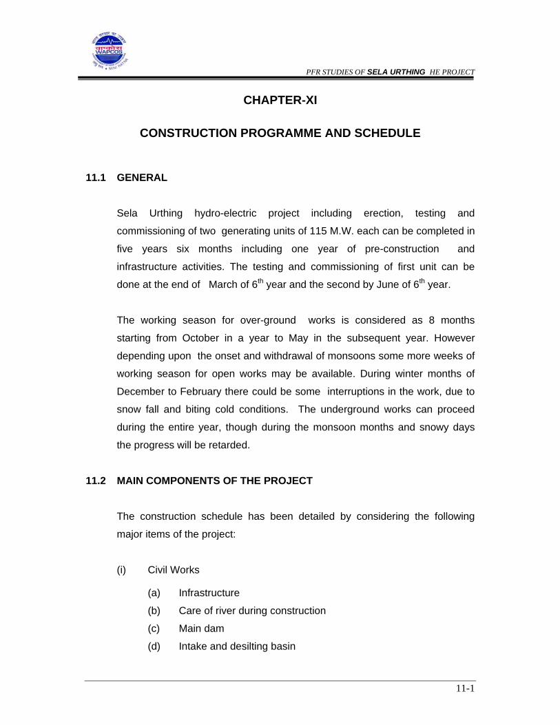
PFR STUDIES OF SELA URTHING HE PROJECT
11-1
CHAPTER-XI
CONSTRUCTION PROGRAMME AND SCHEDULE
11.1 GENERAL
Sela Urthing hydro-electric project including erection, testing and
commissioning of two generating units of 115 M.W. each can be completed in
five years six months including one year of pre-construction and
infrastructure activities. The testing and commissioning of first unit can be
done at the end of March of 6th year and the second by June of 6th year.
The working season for over-ground works is considered as 8 months
starting from October in a year to May in the subsequent year. However
depending upon the onset and withdrawal of monsoons some more weeks of
working season for open works may be available. During winter months of
December to February there could be some interruptions in the work, due to
snow fall and biting cold conditions. The underground works can proceed
during the entire year, though during the monsoon months and snowy days
the progress will be retarded.
11.2 MAIN COMPONENTS OF THE PROJECT
The construction schedule has been detailed by considering the following
major items of the project:
(i) Civil Works
(a) Infrastructure
(b) Care of river during construction
(c) Main dam
(d) Intake and desilting basin
PFR STUDIES OF SELA URTHING HE PROJECT
11-2
(e) Head race tunnel
(f) Penstocks
(g) Surface power house including switch yard etc.
(h) Tail race works
(2) Electrical Works
(a) E.O.T. crane
(b) Supply and erection of T.G. sets
(c) Switch yard and transformers
(d) Other auxiliary equipment
(3) Hydro mechanical works
(a) Main dam gates and stoplogs
(b) Intake gates
(c) Gates for desilting basin
(d) Surge shaft gate
(e) Draft tube gates
The details of the works are given in the salient features of the project
11.3 CONSTRUCTION SCHEDULE
The total construction period can be scheduled as follows:
Total construction period including one year of
infrastructure and pre-construction activities
5 years 6 months
Commissioning of Unit one --- March of 6th year
Commissioning of Unit two --- June of 6th year
The programme in the form of a bar chart is attached.
PFR STUDIES OF SELA URTHING HE PROJECT
11-3
11.4 INFRASTRUCTURE FACILITIES
The creation of infrastructure facilities can be taken up in the beginning of
first year. Construction of project roads, construction roads to quarry sites,
tunnel portals etc can be completed during the year.
The construction of office, residential buildings and other buildings can also
be started in the first year and phased over to second year as per
requirement. The facilities like workshops, fabrication yards, stores, magazine
etc. which will also be started in the first year and will be completed as per the
needs of actual works.
11.5 MAIN DAM
For care of river during construction, a diversion tunnel on the left bank of
river and semi permanent coffer dams of small heights are considered. The
excavation of the diversion tunnel will be started in the first year and with
working from both the upstream and downstream ends, the diversion tunnel
can completed in nine months. The upstream and downstream (if needed)
coffer dams, which will be of semi permanent type with colcrete / plum
concrete will be completed in the last quarter of the first year to facilitate
diversion by the beginning of 2nd year. During the second and subsequent
diversions the coffer dams may require only minor repairs / restoration.
The excavation for the dam at the abutments will be taken up in the first year
itself after the rainy season and all the excavation including river bed portion
after river diversion can be completed before the end of second year.
The work of foundation treatment will start as the excavation of foundation
progresses and the all the consolidation work can be completed before June
of third year. The curtain grouting and drainage holes work will be done
through the foundation grouting provided in the dam after the dam blocks

PFR STUDIES OF SELA URTHING HE PROJECT
11-4
have reached about 8-10 m above the gallery and completed before reservoir
filling.
The concreting for the main dam NOF and spillway blocks including Stilling
basin will be started in the last quarter of 2nd year and completed in all
respects by the end of 5th year. The erection of spillway gates and stop log
will also be competed by this time.
11.6 INTAKE AND DESILTING BASIN
The work of intake will be taken up from the beginning of second year and
completed in all respects by the June of third year.
The works of desilting basin can be started from the beginning of third year
and completed by June of fourth year.
11.7 HEAD RACE TUNNEL, SURGE SHAFT, PENSTOCK AND TAIL RACE
The length of the H.R.T. is only about 2.01 m and the work can be started
from dam side after creating an approach from October of second year and
can also excavated from surge shaft end after this face is available. All the
works of HRT including adit, tunnel excavation, concreting and grouting will
be completed by the end fourth year as shown in the bar chart.
The penstock will be taken up by March of second year and the entire work
can be completed by the end of fourth year as shown in the construction
schedule bar chart. The works of tail race can be easily done in 9 months and
completed by the middle of 4th year.

PFR STUDIES OF SELA URTHING HE PROJECT
11-5
11.8 POWER HOUSE
The power house is planned as a surface power house on the right bank
terrace of the river. The excavation for the power house can be started from
October of first year and all the works including sub-structure and super
structure can be completed along with the installation of electro-mechanical
equipment of the three units by the end of fifth year as shown in the bar chart.
11.9 TESTING AND COMMISSIONING
The first unit can be commissioned after testing by the end of March of sixth
year and the second unit by June of sixth year.

PFR STUDIES OF SELA URTHING HE PROJECT
12-1
CHAPTER-XII
COST ESTIMATE 12.1 Introduction
The Sela Urthing hydroelectric project envisages construction of a 73 m high
concrete gravity dam above the deepest foundation level about 450 m
downstream of Sela village on Dhauliganga river. The surface power house is
located on the right bank of Dhauliganga river on the downstream of
confluence of Misling Gad and Syanyar Ki Dhar on either bank with
Dhauliganga river. The major works of the project, include dam, intakes, an
underground desilting basin, a 2.01 km long HRT, penstock, surface power
house and tail race works. The salient features of the project are given in the
report. The power house will have an installed capacity 230 MW (2x115 MW).
12.2 The Project is estimated to cost Rs. 570.60 crores million at June 2003 price
level. The break down of cost is given below :
Item Estimated Cost ( Rs. Crores )
Civil Works 356.88
Electrical Works 213.72
Sub Total (Generation) 570.60
Say 571/-
The project estimate has been prepared on the basis of “ Guidelines for
preparation of cost estimates for River Valley projects” published by Central
Water Commission, New Delhi. The abstract of cost is enclosed as
Annexure 12.1. The above cost does not include the cost of transmission.
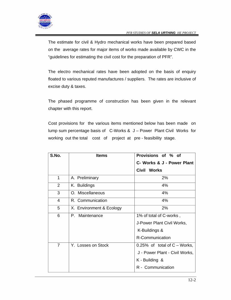
PFR STUDIES OF SELA URTHING HE PROJECT
12-2
The estimate for civil & Hydro mechanical works have been prepared based
on the average rates for major items of works made available by CWC in the
“guidelines for estimating the civil cost for the preparation of PFR”.
The electro mechanical rates have been adopted on the basis of enquiry
floated to various reputed manufactures / suppliers. The rates are inclusive of
excise duty & taxes.
The phased programme of construction has been given in the relevant
chapter with this report.
Cost provisions for the various items mentioned below has been made on
lump sum percentage basis of C-Works & J – Power Plant Civil Works for
working out the total cost of project at pre - feasibility stage.
S.No. Items Provisions of % of C- Works & J - Power Plant Civil Works
1 A. Preliminary 2%
2 K. Buildings 4%
3 O. Miscellaneous 4%
4 R. Communication 4%
5 X. Environment & Ecology 2%
6 P. Maintenance 1% of total of C-works ,
J-Power Plant Civil Works,
K-Buildings &
R-Communication
7 Y. Losses on Stock 0.25% of total of C – Works,
J - Power Plant - Civil Works,
K - Building &
R - Communication

PFR STUDIES OF SELA URTHING HE PROJECT
12-3
12.3 Electro-Mechanical Works 12.3.1 The details of the estimates for Electro-Mechanical works has been estimated
as Rs. 213.72 crores. Various details of different components are given in
Annex. 12.2.
12.3.2 The cost of power evacuation for this project has been arrived at Rs.33.75
crores.

1 Surface Excavation
1.1 Common excavtion M3 700 125 0.88
1.2 Rock excavation M3 700 300 2.10
2 Underground Excavation M3 20000 1000 200.00
3 Support System
3.1 Rockbolts RM 10000 400 40.00
3.2 Shotcreting M3 500 4000 20.00
4 Concrete
4.1 Lining M-20 M3 1500 4000 60
4.2 M-20 M3 50 3390 1.695
Sub-Total (A) 324.67
5 Miscellaneous and Ancillary Works
5.1 Various miscellaneous works like drilling &
grouting, wiremesh reinforcement, slope protection
works, othr steel works etc. 2% 6.49
Sub-Total (B) 331.16
6 Dewatering 3% of subtotal B 1% 9.93
7 Contingencies 3% of subtotal B 1% 9.93
8 Workcharged establishment 2% of subtotal B 6.62
Total 357.66
Say 358.00
C-Works-1
SELA URTHING HYDRO ELECTRIC PROJECT
COST ESTIMATE - DIVERSION TUNNEL
Amount (Rs. in Lakh)
Sl.No. Item of Work Unit Qty Rate (Rs.)
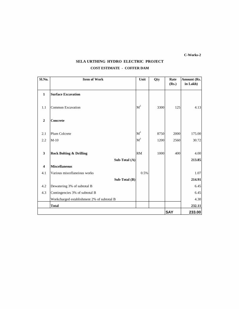
1 Surface Excavation
1.1 Common Excavation M3 3300 125 4.13
2 Concrete
2.1 Plum Colcrete M3 8750 2000 175.00
2.2 M-10 M3 1200 2560 30.72
3 Rock Bolting & Drilling RM 1000 400 4.00
Sub-Total (A) 213.85
4 Miscellaneous
4.1 Various miscellaneious works 0.5% 1.07
Sub-Total (B) 214.91
4.2 Dewatering 3% of subtotal B 6.45
4.3 Contingencies 3% of subtotal B 6.45
Workcharged establishment 2% of subtotal B 4.30
Total 232.11
SAY 233.00
Unit Qty Rate (Rs.)
Amount (Rs. in Lakh)
Item of Work Sl.No.
C-Works-2
SELA URTHING HYDRO ELECTRIC PROJECT
COST ESTIMATE - COFFER DAM

1 Surface Excavation
1.1 Common Excavation M3 91000 125 113.75
1.2 Rock Excavation M3 39000 300 54.00
2 Support System
2.1 Rockbolts / rock anchors RM 1500 400 6.00
2.2 Shotcreting M3 500 4000 20.00
3 Concrete
3.1 M 15 M3 170000 2930 4981.00
3.2 M 20 M3 55000 3390 1864.50
4 Reinforcing Steel MT 2500 27000 675.00
Sub-Total (A) 7714.25
5 Miscellaneous
5.1 Various miscellaneious works like wiremesh/steel fibre
reinforcement,drilling & grouting PVC pipes, other
steel works, slope protection works, elevator, road
works, archktectural works for dam etc. 3% 231.43
Sub-Total (B) 7945.68
6 Instrumentation 1% of subtotal B 79.46
7 Dewatering 2% of subtotal B 158.91
8 Contingencies 3% of subtotal B 238.37
9 Workcharged establishment 2% of subtotal B 158.91
Total 8581.33
Say 8582.00
Rate (Rs.)
Amount (Rs. in Lakh)
Sl.No. Item of Work Unit Qty
C-Works-3
SELA URTHING HYDRO ELECTRIC PROJECT
COST ESTIMATE - CONCRETE DAM

1 Surface Excavation
1.1 Common excavation M3 18000 125 22.50
1.2 Rock excavation M3 18000 300 54.00
2 Underground Excavation M3 20000 1000 200.00
3 Support System
3.1 Rockbolts RM 2200 400 8.80
3.2 Shotcreting M3 500 4000 20.00
4 Concrete
4.1 M-20 M3 3500 3390 118.65
4.2 Cement Lining M-20 M3 3000 4000 120.00
4.3 M-15 M3 3500 2930 102.55
5 Reinforcing Steel T 350 27000 94.50
Sub-Total (A) 741.00
6 Miscellaneous
6.1 Various miscellaneious works like wiremesh/steel fibre
reinforcement,drilling & grouting PVC pipes
for drainage, slope protection works etc. 8% 59.28
Sub-Total (B) 800.28
7 Instrumentation 1% of subtotal B 8.00
8 Dewatering 2% of subtotal B 16.01
9 Contingencies 3% of subtotal B 24.01
10 Workcharged establishment 2% of subtotal B 16.01
Total 864.30
Say 865.00
SELA URTHING HYDRO ELECTRIC PROJECT
COST ESTIMATE - INTAKE STRUCTURE + INTAKE TUNNELS
Sl.No. Item of Work Unit Qty Rate (Rs.)
Amount (Rs. in Lakh)
J-Power Plant Civil Works-1

1 Underground Excavation M3 120000 1000 1200.00
2 Support System
2.1 Rockbolts RM 18000 400 72.00
2.2 Shotcreting M3 1500 4000 60.00
3 Concrete Lining
3.1 Cement Lining M-20 M3 15000 4000 600.00
4 Reinforcing Steel MT 900 27000 243.00
Sub-Total (A) 2175.00
5 Miscellaneous and Ancillary Works
5.1 Various Miscellaneous works like wiremesh/steel
fibre reinforcement, drilling & grouting etc. 4% 87.00
Sub-Total (B) 2262.00
6 Dewatering 2% of subtotal B 45.24
7 Contingencies 3% of subtotal B 45.24
8 Workcharged establishment 2% of subtotal B 45.24
Total 2397.72
Say 2198.00
Amount (Rs. in Lakh)
SELA URTHING HYDRO ELECTRIC PROJECT
Item of Work Unit
J-Power Plant Civil Works-2
COST ESTIMATE DESILTING CHAMBER & SILT FLUSHING TUNNEL
Rate (Rs.)
QtySl.No.
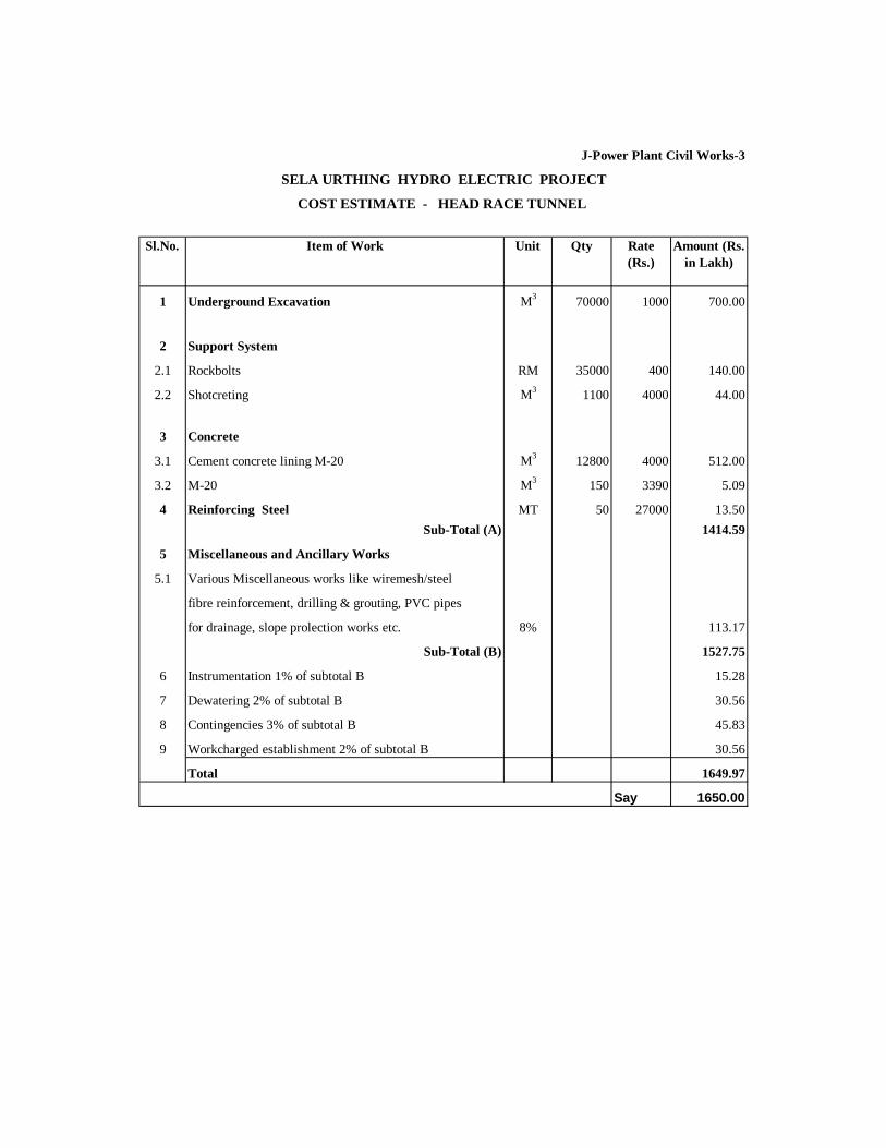
1 Underground Excavation M3 70000 1000 700.00
2 Support System
2.1 Rockbolts RM 35000 400 140.00
2.2 Shotcreting M3 1100 4000 44.00
3 Concrete
3.1 Cement concrete lining M-20 M3 12800 4000 512.00
3.2 M-20 M3 150 3390 5.09
4 Reinforcing Steel MT 50 27000 13.50Sub-Total (A) 1414.59
5 Miscellaneous and Ancillary Works
5.1 Various Miscellaneous works like wiremesh/steel
fibre reinforcement, drilling & grouting, PVC pipes
for drainage, slope prolection works etc. 8% 113.17
Sub-Total (B) 1527.75
6 Instrumentation 1% of subtotal B 15.28
7 Dewatering 2% of subtotal B 30.56
8 Contingencies 3% of subtotal B 45.83
9 Workcharged establishment 2% of subtotal B 30.56
Total 1649.97
Say 1650.00
Unit QtyItem of Work Sl.No. Rate (Rs.)
Amount (Rs. in Lakh)
J-Power Plant Civil Works-3
COST ESTIMATE - HEAD RACE TUNNEL
SELA URTHING HYDRO ELECTRIC PROJECT

1 Surface Excavation M3 100000 300 300.00
2 Concrete
2.1 M-20 M3 7000 3390 237.30
2.2 M-15 backfill concrete M3 13500 2930 395.55
3 Penstock Steel Liners MT 1000 70000 700.00
4 Reinforcement MT 1000 27000 270.00
Sub-Total (A) 1902.85
5 Miscellaneous and Ancillary Works
5.1 Various Miscellaneous works like drilling &
& grouting, wiremesh/steel fibre reinforcement,
swellex anchor, etc. 3% 57.09
Sub-Total (B) 1959.94
5.2 Instrumentation 1% of subtotal B 19.60
5.3 Dewatering 1% of subtotal B 19.60
5.4 Contingencies 3% of subtotal B 58.80
Workcharged establishment 2% of subtotal B 39.20
Total 4057.07
Say 4057.00
SELA URTHING HYDRO ELECTRIC PROJECT
Unit QtySl.No.
J-Power Plant Civil Works-4
Item of Work
COST ESTIMATE - PENSTOCKS
Rate (Rs.)
Amount (Rs. in Lakh)

1 Common Excavation M3 5000 125 6.25
2 Underground Excavation
2.1 Surge shaft excavation M3 9000 1200 108.00
2.2 Surge shaft excavation with raise climber M3 1000 1500 15.00
3 Support System
3.1 Rockbolts RM 1800 400 7.20
3.2 Shotcreting M3 100 4000 4.00
4 Concrete
4.1 Concrete Lining M3 800 4000 32.00
Sub-Total (A) 166.20
5 Miscellaneous and Ancillary Works
5.1 Various miscellaneious works like site clearance,
drilling & grouting, wire mesh reinforcement,
Airvent pipes, lift arrangement, other steel works etc. 2% 3.32
Sub-Total (B) 169.52
6 Instrumentation 1% of subtotal B 1.70
7 Dewatering 1% of subtotal B 1.70
8 Contingencies 3% of subtotal B 5.09
9 Workcharged establishment 2% of subtotal B 3.39
Total 181.39
Say 182.00
Item of Work Unit Qty Amount (Rs. in Lakh)
COST ESTIMATE - SURGE SHAFT
J-Power Plant Civil Works-5
SELA URTHING HYDRO ELECTRIC PROJECT
Sl.No. Rate (Rs.)

1 Surface Excavation 1.1 Common excavation M3 50000 125 62.501.2 Excavation in hard rock M3 500000 300 1500.00
2 Concrete 2.1 M-15 M3 9000 2560 230.402.2 M-20 M3 2000 3390 67.80
3 Reinforcing Steel MT 500 27000 135.00
4 Structural Steel for roof trusses T 50 42000 21.00
5 Stone/Brick Masonry LS 15.00Sub-Total (A) 2031.70
6 Miscellaneous6.1 Various miscellaneous works like site clearance,
drilling & grouting, wiremesh/steel fibre, reinforcement, flooring, water proofing systemswellex anchor, doors & windows,painting, liftarrangement, architectural works, other metalworksetc. 5% 101.59
Sub-Total (B) 2133.297 Instrumentation 1% of subtotal B 21.338 Dewatering 2% of subtotal B 42.679 Contingencies 3% of subtotal B 64.00
10 Workcharged establishment 2% of subtotal B 42.67Total 4437.23
Say 4438.00
Amount (Rs. in Lakh)
Sl.No.
COST ESTIMATE - POWER HOUSE COMPLEX
SELA URTHING HYDRO ELECTRIC PROJECT
J-Power Plant Civil Works-6
Rate (Rs.)
Unit QtyItem of Work
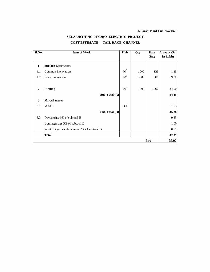
1 Surface Excavation
1.1 Common Excavation M3 1000 125 1.25
1.2 Rock Excavation M3 3000 300 9.00
2 Linning M3 600 4000 24.00
Sub-Total (A) 34.25
3 Miscellaneous
3.1 MISC. 3% 1.03
Sub-Total (B) 35.28
3.3 Dewatering 1% of subtotal B 0.35
Contingencies 3% of subtotal B 1.06
Workcharged establishment 2% of subtotal B 0.71
Total 37.39
Say 38.00
COST ESTIMATE - TAIL RACE CHANNEL
Sl.No. Amount (Rs. in Lakh)
Item of Work Rate (Rs.)
Unit
J-Power Plant Civil Works-7
SELA URTHING HYDRO ELECTRIC PROJECT
Qty

S.No. Item Unit Oty Rate Amount
1 DIVERSION TUNNEL WORK
Gate MT 35 100000 35.00
Embedded Parts MT 12 50,000 6.00
Rope Drum Hoist (as per capacity) Set 1 6000000 60.00
2 SPILLWAY STRUCTURE
a Radial Gates MT 400 100000 400.00
Embedded Parts (Including anchorages) MT 130 50,000 65.00
Hydraulic hoist Set 4 20000000 800.00
b Bulkhead Gates (Sizes) MT 120 100000 120.00
Embedded Parts MT 120 50,000 60.00
Gantry Crane Set 1 3000000 30.00
3 INTAKE STRUCTURE
a Intake Gate MT 50 100000 50.00
Embedded Parts for Intake Gate MT 20 50,000 10.00
Rope drum hoist (as per capacity) Set 2 3500000 70.00
b Bulkhead Gates (Sizes) MT 20 50,000 10.00
Embedded Parts for Bulkhead Gates MT 10 50,000 5.00
Gantry Crane (as per capacity) Set 1 1500000 15.00
4 TRASH RACKS/TRASH RACK CLEANNING MACHINE
Trash Racks and Embedded Parts MT 125 50000 62.50
5 SURGE SHAFT
a Gate MT 40 100000 40.00
b Embedded Parts MT 15 50,000 7.50
c Hoist Set 1 4500000 45.00
6 DESILTING CHANNEL/SILT FLUSING/D.T.
Gate MT 60 110000 66.00
Embadded Parts MT 20 50000 10.00
Hoist/Hydrolic Set 2 3000000 60.00
J - Power Plant Civil Work - 8
SELA URTHING HYDRO ELECTRIC PROJECT
COST ESTIMATE - HYDRO - MECHANICAL WORKS

2027.00
Say 2027.00

1 Surface Excavation
1.1 Common excavtion M3 150000 125 187.50
1.2 Rock excavation M3 50000 300 150.00
2 Concrete
2.1 M15 M3
2.2 M20 M3 2000 3390 67.80
2.3 M25 M3
3 Deformed Reinforcing Bars T 300 27000 81.00
4 Stone / Brick Masonry LS 50.00
Sub-Total (A) 536.30
5 Miscellaneous
5.1 Various miscellaneous works like site clearance,
PVC pipes, control block building works like
flloring, doors, windows, etc inc, water supply and
sewarage, boulder pitching, Metalworks etc. 5% 26.82
Sub-Total (B) 563.12
6 Dewatering 2% of subtotal B 0.54
7 Contingencies 3% of subtotal B 0.80
8 Workcharged establishment 2% of subtotal B 0.54
Total 1259.11
Say 1260.00
Unit Amount (Rs. in Lakh)
Qty Rate (Rs.)
J - POWER PLANT CIVIL WORKS - 9
SELA URTHING HYDRO ELECTRIC PROJECT
COST ESTIMATE - SWITCHYARD
Sl. No.
Item of work
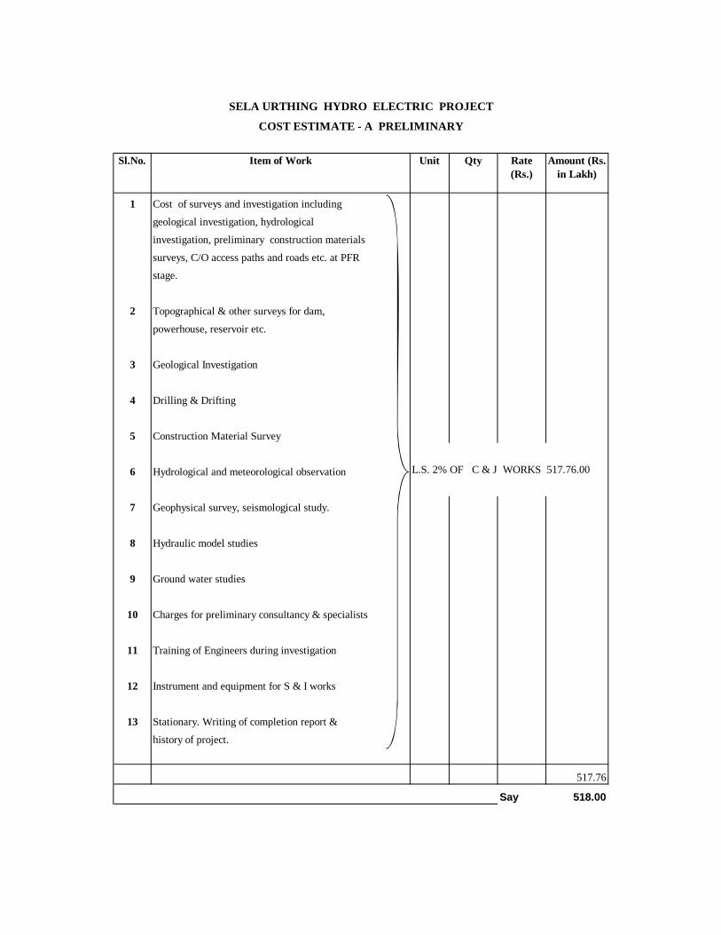
1 Cost of surveys and investigation including
geological investigation, hydrological
investigation, preliminary construction materials
surveys, C/O access paths and roads etc. at PFR
stage.
2 Topographical & other surveys for dam,
powerhouse, reservoir etc.
3 Geological Investigation
4 Drilling & Drifting
5 Construction Material Survey
6 Hydrological and meteorological observation
7 Geophysical survey, seismological study.
8 Hydraulic model studies
9 Ground water studies
10 Charges for preliminary consultancy & specialists
11 Training of Engineers during investigation
12 Instrument and equipment for S & I works
13 Stationary. Writing of completion report &
history of project.
517.76
Say 518.00
SELA URTHING HYDRO ELECTRIC PROJECT
COST ESTIMATE - A PRELIMINARY
Rate (Rs.)
Item of Work Unit Sl.No.
L.S. 2% OF C & J WORKS 517.76.00
Amount (Rs. in Lakh)
Qty
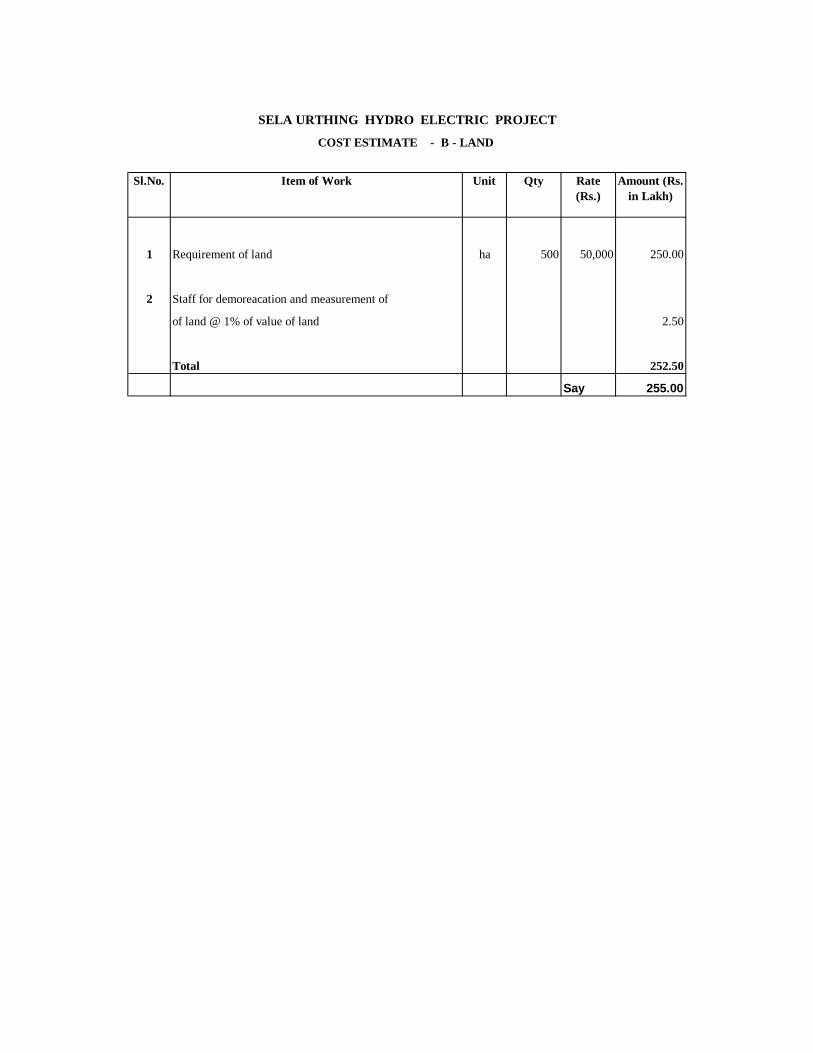
1 Requirement of land ha 500 50,000 250.00
2 Staff for demoreacation and measurement of
of land @ 1% of value of land 2.50
Total 252.50
Say 255.00
Qty
SELA URTHING HYDRO ELECTRIC PROJECT
Sl.No. Item of Work Amount (Rs. in Lakh)
COST ESTIMATE - B - LAND
Rate (Rs.)
Unit

1 Residential Buildings
1.1 Permanent residential buildings
Services Charges @
1.2 Temorary Buildings
Servoces Charges @
Total Residential Buildings
Non Residential Buildings
2.1 Permanent non-residential buildings
Services Charges @
2.2.
Services Charges @
Total Non-residential Buildings
Grant Total ( Residential + Non-Residential) 1035.52
Say 1036.00
L.S. 4 % OF C & J Work 1035.52
Item of Work Sl.No. Unit Qty Amount (Rs. in Lakh)
Rate (Rs.)
COST ESTIMATE - K - BUILDINGS
SELA URTHING HYDRO ELECTRIC PROJECT

1 Inspection and Transport Vehicles
Staff Car no 8 3.75 30.00Gypsy / Jeep no 24 3.75 90.00Amulance no 4 8 32.00School / Staff Bus no 4 6.5 26.00Mini Truck no 8 5 40.00Truck 10 ton no 10 8 80.00
2 Miscellaneous Equipments
Crane 50 ton no 4 155 620.00Carane 18 ton no 4 75 300.00Carane 10 ton no 4 45 180.00DG sets 500 KVA no 8 25 200.00Welding set no 8 2.25 18.00Tractor Trailor no 4 18 72.00Weight Bridge-20 ton no 4 8 32.00Explosive Van 10 ton no 4 6 24.00Pump 5 HP no 40 0.2 8.00Pump 10 HP no 20 0.3 6.00Pump 50 HP no 20 1 20.00
3 Workshop Equipments
Lathe machine no 4 4 16.00Shaper machine no 4 1 4.00Bench Drilling machine no 4 0.7 2.80Grinder no 8 0.15 1.20Drill Steel Grinder no 4 0.75 3.00Power hacksw no 12 0.25 3.00Hydrulic jack no 4 0.5 2.00Engine repair shop no 4 0.15 0.60Auto-electrical repair shop no 4 1.25 5.00Battery charger no 4 1.00Compressor for tyre inflation no 4 0.30Gas cutting set no 12 7.50Unforeseen item no 15.00Total cost of special tools and plants 1839.40
Say 2000.00
Amount (Rs. in Lakh)
NOTE : The project has been planned for construction through private agencies. The contractor shall arrange heavy equipments for works for which no provision has been kept under Q - Special T&P.
SELA URTHING HYDRO ELECTRIC PROJECT
Unit Qty Rate (Rs.)
COST ESTIMATE - Q - SPECIAL T&P
Item of work Sl.No.

Sl.NO. ITEM Qty. Unit Rate Unit Amount (In Rs. Lakhs)
Total Amount (In Rs. Lakhs)
Rate Amount (In Rs. Lakhs)
1 2 3 4 5 6 7 8 9 10
1 Generating Unit and Bus Duct 115 MW, 300 RPM, 259.55 M Head
2 Nos. 0.045 Rs(lakhs)/kW 10350 16% 1656 12006.00
2 Step up transformer 11/220/ 3 kV,45 MVA, Single Phase 7 Nos. 240 Rs./kVA 756 16% 120.96 876.963 Auxiliaries Electrical Equipment for power Stations (
5% of item 1)517.5 16% 82.8 600.30
4 Auxiliary Equipment and services for power stations (5% of item 1)
517.5 16% 82.8 600.30
5 Switchyard-GIS -220 kV 6 bays 300 Rs. Lakhs/bay 1800 16% 288 2088.006 Spares( 5% of 1 and 3% of 2-5) 625.23 625.237 Sub- total(1) 14566.23 2230.56 16796.798 Central Sales Tax @ 4% of item 7 671.879 Transportation & Insurance @ 6% of item 7 1007.81
10 Erection and Commissioning @ 8% of item 7 Except Spares
1293.72
11 Sub- total(2) 19770.1912 Establishment, Contingency, other Charges @ 11% of item
7 excluding duties1602.29
GRAND TOTAL 21372.48
Excise Duty
SCHEME NAME -SELA URTHINGCOST ESTIMATE OF ELECTRO-MECHANICAL WORKS FOR PRE - FEASIBILTY REPORT
Annexure-12.2

PFR STUDIES OF SELA URTHING HE PROJECT
13-1
CHAPTER – XIII
ECONOMIC EVALUATION
13.1 GENERAL
The economic and financial evaluation of the Sela Urthing H.E project has
been considered as per the standard guidelines issued by Central Electricity
Authority and the norms laid down by the Central Electricity Regulatory
Commission (CERC) for Hydro projects have been kept in view in this regard.
13.2 PROJECT BENEFITS 13.2.1 The scheme would afford on annual energy generation of 816.73 GWh in a
90% dependable year. For assessing the tariff, design energy generation of
803.42 GWh , calculated with 95% capacity availability in a 90% dependable
year, has been adopted. The project would provide 230 MW of peaking
capacity benefits.
13.3 CAPITAL COST
The project cost has been estimated at Rs. 570.60 crores without IDC based
on the criteria for “Adoption of Rates and Cost for preparation of PFRs of
hydro-electric projects” issued by CEA and is as given below:
1. Cost of civil works = Rs. 356.88 Crores
2. Cost of Electrical/Mechanical works = Rs. 213.72 Crores
Total = Rs.570.60 Crores
PFR STUDIES OF SELA URTHING HE PROJECT
13-2
13.4 MODE OF FINANCING
The project is proposed to be financed with a debt equity ratio of 70:30. An
interest rate of 10% on the loan component has been considered for the
financial analysis of the project. The interest on the working capital is taken
as 9.75%.
13.5 PHASING OF EXPENDITURE
The project is proposed to be completed in 5.5 years period in all respect with
full benefit available after 5.5 years. The detailed year wise phasing of
expenditure based upon the above construction programme for Civil &
Electrical works is given in Annexure 13.1.
13.6 FINANCIAL ANALYSIS 13.6.1 Basic and Normative Parameters
The following basic parameters have been adopted for working out the
financial analysis of the project.
i) Estimated capital cost of Rs. 662.98Crores considering the Interest
during construction.
ii) Annual energy generation of 816.73 GWh in 90% dependable year and
Design energy of 803.42 GWh.
iii) Operation & maintenance expenses (including insurance) @ 1.5% of
the project cost in the first year with 5% escalation every year.
iv) Depreciation @ 3.5 % has been considered on an average basis.
v) Auxiliary consumption @ 0.7 % of the energy generated.
vi) Transformation loss @ 0.5% of the energy generated.
vii) Interest on working capital @ 9.75%.
PFR STUDIES OF SELA URTHING HE PROJECT
13-3
viii) Interest during construction has been worked out based upon the
interest rates as mentioned above. The computations are given in
Annexure 13.2 for present day capital cost.
ix) Corporate tax @ 30%.
x) Return on equity @ 16%.
13.6.2 ASSESSMENT OF TARIFF
Based upon the parameters given above, the sale rate of energy at bus bar
has been computed in Annexure 13.3. The sale rate applicable in the first
year and levellised tariff is indicated below.
Table – 13.2
Tariff Period
Tariff (Rs./KWh)
First Year
Levellised Tariff
1.40
1.22
13.7 CONCLUSION
The sale rate of energy indicated above shows that the energy generated
from the project is financially viable and economically attractive.

Annexure 13.2
Debt : Equity 70 : 30Interest rate @ 10 %
(INR crores)
Year Project Equity Loancost component component Cummulative IDC Equity for Loan for TOTAL Capitalised
(30%) (70%) loan 10.0% IDC IDC IDC IDC cost(6) x 0.30 (6) x 0.70 10.0%
1 2 3 4 5 6 7 8 9 10 11
1 57.06 57.06 0.00 0.00 0.00 0.00 0.00 0.00 0.00 57.062 142.65 114.12 28.53 28.53 1.43 0.43 1.00 0.05 1.48 144.133 142.65 0.00 142.65 171.18 9.99 3.00 6.99 0.45 10.43 153.084 114.12 0.00 114.12 285.30 22.82 6.85 15.98 1.60 24.42 138.545 57.06 0.00 57.06 342.36 31.38 9.41 21.97 3.49 34.88 91.94
6th (half year) 57.06 0.00 57.06 399.42 18.54 5.56 12.98 2.62 21.17 78.23
Total 570.60 171.18 399.42 84.16 25.25 58.91 8.21 92.38 662.98
SELA URTHING HYDEL SCHEME ( Surface Power House )
Calculation of Interest During Construction
ITERATION - I GRAND TOTAL
(Civil & E&M)
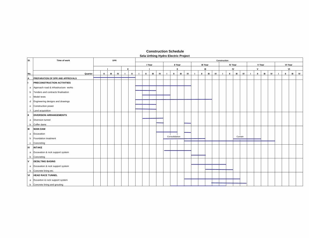
Sl. Time of work
V
No. Quarter II III IV I II I II III IV I II III IV I II III IV I II III IV I II III IV I II III IV
A PREPARATION OF DPR AND APPROVALS
I PRECONSTRUCTION ACTIVITIES
a Approach road & infrastructure works
b Tenders and contracts finalisation
c Model tests
d Engineering designs and drawings
e Construction power
f Land acquisition
II DIVERSION ARRANGEMENTS
a Diversion tunnel
b Coffer dams
III MAIN DAM
a Excavation
b Foundation treatment
c Concreting
IV INTAKE
a Excavation & rock support system
b Concreting
V DESILTING BASINS
a Excavation & rock support system
b Concrete lining etc.
VI HEAD RACE TUNNEL
a Excavtion & rock support system
b Concrete lining and grouting
Construction ScheduleSela Urthing Hydro Electric Project
II Year
II
I Year
DPR
VI
III Year
I II III IVI
Construction
Consolidation Curtain
V Year VI Year IV Year

Sl. Time of work
V
No. Quarter II III IV I II I II III IV I II III IV I II III IV I II III IV I II III IV I II III IV
Construction ScheduleSela Urthing Hydro Electric Project
II Year
II
I Year
DPR
VI
III Year
I II III IVI
Construction
V Year VI Year IV Year
VII PENSTOCKS
a Excavation
b Concrete
c Fabrication and erection
VIII POWER HOUSE
a CIVIL WORKS
- Excavation
- Substructure concrete
- Superstructure concrete
b ELECTRICAL WORKS
- Procurement of Electro-mechanical equipment
- Erection of E.O.T. crane
- Erection of turbines, generators etc.
IX TAIL RACE WORKS
a Excavation
b Concrete
X HYDRO MECHANICAL WORKS
a Spillway gates
b Spillway stoplog
c Intake gates
d Gates for desilting basin
e Surge shaft/tail race gates
XI TESTING AND COMMISIONING 1 Unit
Unit I 2 Unit
Unit II
NOTES : 1. The year is taken as calendar year and the quarters I-January to March, II-April to June, III-July to September and IV-October to December
2. The quarter July to September is of rainy season and the open works shall mostly stop. (for HM & E&M works) Erection
Legend
Fabrication