Embed Size (px)
Citation preview
Georgios Tsionis, Roberta Apostolska, Fabio Taucer
Seismic strengthening of RC buildings
2014
Report EUR 26945 EN
European Commission
Joint Research Centre Institute for the Protection and Security of the Citizen
Contact information
Georgios Tsionis Address: Joint Research Centre, Via Enrico Fermi 2749, TP 480, 21027 Ispra (VA), Italy E-mail: [email protected] Tel.: +39 0332 78 9484
JRC Science Hub https://ec.europa.eu/jrc
Legal Notice
This publication is a Science and Policy Report by the Joint Research Centre, the European Commission’s in-house science service. It aims to provide evidence-based scientific support to the European policy-making process. The scientific output expressed does not imply a policy position of the European Commission. Neither the European Commission nor any person acting on behalf of the Commission is responsible for the use which might be made of this publication.
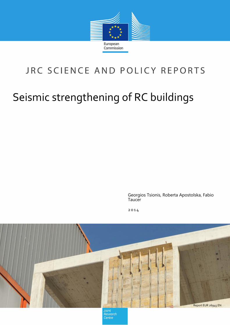
Cover image © European Union 2014
JRC91949
EUR 26945 EN
ISBN 978-92-79-44350-3
ISSN 1831-9424
doi:10.2788/138156
Luxembourg: Publications Office of the European Union, 2014
© European Union, 2014
Reproduction is authorised provided the source is acknowledged.
Abstract
A literature review on the seismic strengthening of reinforced concrete buildings, using steel bracings, infills and shear walls, is presented. Extensive experimental testing and numerical analyses of elements and structures have demonstrated the feasibility and effectiveness of all three measures for the increase of global strength and stiffness. In certain cases, they provide additional energy dissipation and help reducing irregularities. The selection of the most appropriate technique is based on desired performance levels and on economic and, possibly, other non-technical criteria. The results of previous studies clearly show that infilling an existing bay with reinforced concrete provides the highest increase in strength and stiffness. These studies also indicate that precast panels, steel bracings and masonry infills strengthened with fibre-reinforced polymers or textile-reinforced mortars are able to offer the same degree of improvement. The results available in literature, complemented by parametric numerical analyses, may provide the basis for the development of design guidelines with emphasis on strength and stiffness characteristics and on detailing of the connection between new and existing elements. Indeed, the development of models and their implementation in analysis software is a necessary step towards the wider application of these strengthening techniques.
i
Abstract
A literature review on the seismic strengthening of reinforced concrete buildings, using steel bracings, infills and shear walls, is presented. Extensive experimental testing and numerical analyses of elements and structures have demonstrated the feasibility and effectiveness of all three measures for the increase of global strength and stiffness. In certain cases, they provide additional energy dissipation and help reducing irregularities.
The selection of the most appropriate technique is based on desired performance levels and on economic and, possibly, other non-technical criteria. The results of previous studies clearly show that infilling an existing bay with reinforced concrete provides the highest increase in strength and stiffness. These studies also indicate that precast panels, steel bracings and masonry infills strengthened with fibre-reinforced polymers or textile-reinforced mortars are able to offer the same degree of improvement.
The results available in literature, complemented by parametric numerical analyses, may provide the basis for the development of design guidelines with emphasis on strength and stiffness characteristics and on detailing of the connection between new and existing elements. Indeed, the development of models and their implementation in analysis software is a necessary step towards the wider application of these strengthening techniques.

iii
Table of Contents
List of Figures ......................................................................................................................... v
List of Tables ........................................................................................................................ vii
1 Introduction .................................................................................................................... 1
1.1 GENERAL ............................................................................................................... 1
1.2 RETROFIT MEASURES AND CRITERIA ............................................................... 1
1.3 NON-TECHNICAL CRITERIA ................................................................................. 2
1.4 COST-EFFECTIVENESS CASE STUDY ................................................................ 3
1.5 INCREMENTAL SEISMIC REHABILITATION ........................................................ 4
1.6 SELECTIVE WEAKENING ...................................................................................... 5
2 Strengthening with steel bracings ............................................................................... 7
2.1 OVERVIEW ............................................................................................................. 7
2.2 CONCENTRIC STEEL BRACING ........................................................................... 8
2.3 ECCENTRIC STEEL BRACING ............................................................................ 12
2.4 BUCKLING-RESTRAINED BRACES .................................................................... 14
2.5 METAL SHEAR PANELS ...................................................................................... 18
2.6 RETROFITTING WITH POST-TENSIONED CABLES.......................................... 19
2.7 SUMMARY ............................................................................................................ 19
3 Strengthening with infills ............................................................................................ 23
3.1 OVERVIEW ........................................................................................................... 23
3.2 STRENGTHENING BY MASONRY INFILLS ........................................................ 24
3.3 FRP STRENGTHENING OF MASONRY INFILLS ................................................ 26
3.4 STRENGTHENING BY PRECAST CONCRETE PANELS ................................... 30
3.5 SUMMARY ............................................................................................................ 33
4 Strengthening with RC shear walls ............................................................................ 37
4.1 NEW RC WALLS ................................................................................................... 37
4.2 ROCKING WALLS ................................................................................................ 38
4.3 RC INFILLING ....................................................................................................... 42
4.3.1 Experimental study of squat walls ............................................................. 42
4.3.2 Experimental study of slender walls .......................................................... 43
4.3.3 Summary of experimental studies ............................................................. 45
4.3.4 Numerical studies ...................................................................................... 48
iv
4.4 SUMMARY ............................................................................................................ 48
5 Conclusions .................................................................................................................. 51
References ............................................................................................................................ 53
v
List of Figures
Fig. 1.1 Effectiveness of full and incremental rehabilitation (FEMA 2009) .............................. 4
Fig. 2.1 Different types of bracing systems ............................................................................. 8
Fig. 2.2 Schematic view of X (left) and knee (right) bracing system ....................................... 9
Fig. 2.3 Buttress-type steel shear wall (Kaplan and Yilmaz 2012) ........................................ 10
Fig. 2.4 Strengthening of existing RC frame with indirect bracing (Ishimura et al. 2012) ...... 11
Fig. 2.5 Joints between steel brace and RC frame (Ishimura et al. 2012) ............................ 11
Fig. 2.6 RC frame retrofitted with steel braces and their failure mode (Liu et al. 2012) ........ 12
Fig. 2.7 Flexural (left) and shear failure (right) of the connections of inverted-Y braces (Mazzolani et al. 2007)........................................................................................ 13
Fig. 2.8 Retrofit of RC frames with eccentric braces: a) test assembly, b) storey shear versus displacement and force-displacement of the shear link, c) energy dissipated by the frame and the shear link (Pinto et al. 2002) ........................................................ 14
Fig. 2.9 Experimental setup and response of the buckling-restrained brace with silicone rubber sheets (Tsai et al. 2004) ..................................................................................... 15
Fig. 2.10 Experimental setup and failure mode of buckling-restrained braces (Wada and Nakashima 2004) ................................................................................................ 15
Fig. 2.11 Geometry of existing RC frame and buckling-restrained braces (Mazzolani et al. 2007) ................................................................................................................... 16
Fig. 2.12 General view of frame structure retrofitted with metal shear panels and details of the connections (De Matteis et al. 2007) .................................................................. 18
Fig. 3.1 Flat-slab structure strengthened with masonry infill walls (Pujol et al. 2008) ........... 25
Fig. 3.2 Frame retrofitted by RC infilling (left) and force-displacement envelopes of as-built and retrofitted frames (right) tested by Erdem et al. (2004) ................................ 26
Fig. 3.3 Base shear versus displacement envelopes for bare and infilled frames and damage of infills strengthened with FRP (Yuksel et al. 2005) .......................................... 27
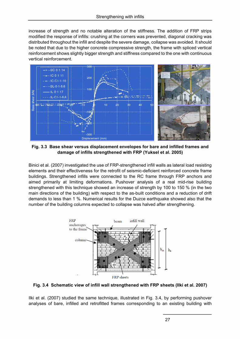
Fig. 3.4 Schematic view of infill wall strengthened with FRP sheets (Ilki et al. 2007) ........... 27
Fig. 3.5 Base shear versus storey displacement of the as-built (1st test) and strengthened (2nd test) buildings (Mazzolani et al. 2007) ................................................................ 28
Fig. 3.6 Alternative CFRP retrofitting schemes used in infilled RC frames ........................... 30
Fig. 3.7 Force-displacement response and damage of three-storey (top) and one-storey (bottom) frames strengthened with precast panels (Higashi et al. 1984) ............ 31
Fig. 3.8 Force-displacement response of a panel and frame connection (Frosch et al. 1996) ............................................................................................................................ 31
Fig. 4.1 View and cross-section above the foundation of RC frames strengthened with new RC walls placed around a column (a), external to the frame (b), or as buttress (c) ............................................................................................................................ 37
Fig. 4.2 Components of rocking wall (Ireland et al. 2007) ..................................................... 39
vi
Fig. 4.3 Force-displacement response of as-built shear wall (left) and rocking wall with dissipators (right) tested by Ireland et al. (2007) ................................................. 40
Fig. 4.4 Damage of specimen with free uplift of wall (left) and fixed wall (right) tested by Mori et al. (2008) ......................................................................................................... 40
Fig. 4.5 Detail of the base and cross-section of pinned wall added to an 11-storey existing frame building (Wada et al. 2009) ....................................................................... 41
Fig. 4.6 Construction of shotcrete wall and damage after testing (Teymur et al. 2008) ........ 43
Fig. 4.7 Force-displacement response of four-storey frame structures strengthened with RC infills (Chrysostomou et al. 2012) ........................................................................ 44
Fig. 4.8 Moment-drift response (left) and crack pattern (right) of four-storey frames strengthened with RC infills (Strepelias 2012) .................................................... 44
vii
List of Tables
Table 1.1 Effect of local and global retrofit measures on building properties .......................... 2
Table 1.2 Initial cost, expected annual loss and benefit-to-cost ratio of different retrofit solutions for a six-storey residential building (Calvi 2012) .................................... 4
Table 2.1 Response parameters of the frames tested by Maheri et al. (2003) ....................... 9
Table 2.2 Performance parameters (average value of nine ground motions) of as-built and braced frames (El-Sokkary and Galal 2009) ....................................................... 10
Table 2.3 Experimental and calculated values of ultimate strength for the specimens tested by Ishimura et al. (2012) ..................................................................................... 11
Table 2.4 Response of as-built and retrofitted frames tested by Liu et al. (2012) ................. 12
Table 2.5 Top displacements for as-built and braced frames (Varum et al. 2013) ................ 14
Table 2.6 Experimental base shear and top displacement of frames strengthened with buckling-restrained braces (Mazzolani et al. 2007) ............................................ 16
Table 2.7 Maximum storey drift (%) of as-built and retrofitted buildings, mean values for seven earthquake records (Di Sarno and Manfredi 2010) ............................................. 17
Table 2.8 Results of pushover analysis of braced building (Di Sarno and Manfredi 2010) ... 17
Table 2.9 Effects of steel bracing retrofit and design considerations (Thermou and Elnashai 2006) ................................................................................................................... 19
Table 2.10 Summary of experiments on frames strengthened with steel braces .................. 20
Table 3.1 Experimental values of drift for infilled frames, adapted from Griffith (2008) ........ 23
Table 3.2 Experimental results for bare and infilled frames (Lee and Woo 2002) ................ 24
Table 3.3 Results of pushover analysis of bare and partially-infilled frames (Lee and Woo 2002) ................................................................................................................... 25
Table 3.4 Results of pushover analysis of existing and retrofitted buildings (Ilki et al. 2007) 28
Table 3.5 Results of non-linear dynamic analysis of frame buildings with FRP-strengthened infills (El-Sokkary and Galal 2009) ...................................................................... 29
Table 3.6 Experimental results of frames strengthened with infills and different configurations of FRP sheets (Yuksel et al. 2010) ..................................................................... 29
Table 3.7 Test results on infilled frames with precast panels (Baran et al. 2011) ................. 32
Table 3.8 Test results for precast panels with various connection details (Darama and Shiohara 2009) ................................................................................................... 33
Table 3.9 Test results of frame structure retrofitted with precast panels (Kurt 2010) ............ 33
Table 3.10 Summary of experiments on frames strengthened with masonry infills and precast concrete panels .................................................................................................. 34
Table 4.1 Summary of experiments on frames strengthened with new RC walls ................. 38
Table 4.2 Summary of experiments on frames strengthened with RC infilling ...................... 46

viii
Introduction
1
1 Introduction
1.1 GENERAL
The majority of existing buildings have been designed and constructed without provisions for seismic resistance and, as demonstrated by research and field observations, they are likely to suffer significant damage even for moderate earthquakes. In addition to the economic loss, seismic-deficient buildings may cause injuries and casualties. The seismic engineering research community has dedicated significant efforts in developing retrofit measures to address these issues.
This report presents a literature review of experimental and numerical investigations on the seismic strengthening of reinforced concrete (RC) buildings, focusing on the use of steel bracings, infills and shear walls. Strengthening is a promising strategy, as nowadays reduced drifts and non-structural damage are becoming important performance requirements. Chapter 1 introduces the available retrofit measures and their possible effects on the local and global response of a building. In addition to the technical aspects, socio-economic requirements affect the choice of the measures to implement, as illustrated in a cost-benefit case study of a real RC building. Two techniques, namely incremental retrofit and selective weakening, that have not been extensively applied and verified are also presented. The various types of steel braces – eccentric, concentric, buckling-restrained and post-tensioned – used for the seismic upgrading of frame buildings are examined in Chapter 2, while Chapter 3 deals with the retrofit of RC buildings using masonry infills, possibly strengthened with fibre-reinforced polymer (FRP) sheets and precast concrete panels. Chapter 0 presents numerical and experimental investigations on the use of RC shear walls for the seismic strengthening of existing RC frame buildings. Practical applications range from new walls constructed externally to the frame, to infilling of bays with reinforced concrete, and the most technologically advanced hybrid walls, i.e. rocking walls with energy-dissipating devices. Finally, the main findings of the reviewed works are summarised in Chapter 5 and issues that require further clarification in view of the development of design guidelines are highlighted.
1.2 RETROFIT MEASURES AND CRITERIA
Assessment of an existing building will reveal the deficiencies at local and global level; the designer will use his/her experience and engineering judgement to select the most appropriate measure or combination of measures to improve the performance of the building. Guidance documents such as the fib Bulletin on Seismic Assessment and Retrofit of Reinforced Concrete Buildings (fib 2003) and the FEMA Techniques for the Seismic Rehabilitation of Existing Buildings (FEMA 2009) provide advice on the cases where each measure is most effective. In general terms, local measures are more appropriate when some elements possess insufficient capacity, whereas global measures are suitable in case of large deformation demands, including the possibility of pounding and irregularities.
The retrofit measures will be selected based primarily on technical criteria. There are two main objectives in seismic retrofit, i.e. to reduce demand or to increase capacity, and three main properties to examine: strength, stiffness and deformation capacity. The most common retrofit
Introduction
2
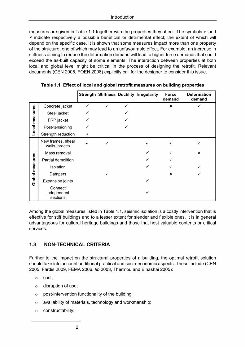
measures are given in Table 1.1 together with the properties they affect. The symbols and indicate respectively a possible beneficial or detrimental effect; the extent of which will depend on the specific case. It is shown that some measures impact more than one property of the structure, one of which may lead to an unfavourable effect. For example, an increase in stiffness aiming to reduce the deformation demand will lead to higher force demands that could exceed the as-built capacity of some elements. The interaction between properties at both local and global level might be critical in the process of designing the retrofit. Relevant documents (CEN 2005, FOEN 2008) explicitly call for the designer to consider this issue.
Table 1.1 Effect of local and global retrofit measures on building properties
Strength Stiffness Ductility Irregularity Force demand
Deformation demand
Lo
cal m
easu
res Concrete jacket
Steel jacket
FRP jacket
Post-tensioning
Strength reduction
Glo
bal
mea
sure
s
New frames, shear walls, braces
Mass removal
Partial demolition
Isolation
Dampers
Expansion joints
Connect independent
sections
Among the global measures listed in Table 1.1, seismic isolation is a costly intervention that is effective for stiff buildings and to a lesser extent for slender and flexible ones. It is in general advantageous for cultural heritage buildings and those that host valuable contents or critical services.
1.3 NON-TECHNICAL CRITERIA
Further to the impact on the structural properties of a building, the optimal retrofit solution should take into account additional practical and socio-economic aspects. These include (CEN 2005, Fardis 2009, FEMA 2006, fib 2003, Thermou and Elnashai 2005):
o cost;
o disruption of use;
o post-intervention functionality of the building;
o availability of materials, technology and workmanship;
o constructability;
Introduction
3
o aesthetics;
o reversibility;
o interaction with building services.
Construction cost is a fundamental parameter. In most cases, it should be examined together with the cost of non-structural interventions (e.g. removal and reconstruction of finishings, temporary measures during construction), the value of the contents of the building and the cost related to the disruption of use of the building (e.g. temporary housing of occupants, business interruption and relocation of services). On the other hand, a building with upgraded seismic safety will lead to higher rental prices and lower insurance premium, which will (at least partially) compensate the rehabilitation cost. The construction cost might not govern, though, in cases of buildings that house expensive equipment and high-revenue business activities. Phipps et al. (1992) report on a building in the Silicon Valley for which, following the 1989 Loma Prieta earthquake, the cost of personnel relocation and business disruption was 200 times higher than the cost of structural and non-structural interventions.
The selection of materials, technologies and workmanship that are not easily available in the region where the building is located will significantly increase construction costs and might render certain measures unfeasible. Practical issues comprise also the ease of access and the available space around the building or element to retrofit (constructability). In this respect, strategies that involve interventions on the foundation are discouraged.
Aesthetics and the architectural value are of concern mainly in historic buildings and they are normally disregarded in other structures. For listed buildings, reversibility is often an additional requirement prescribed in specific codes.
The impact of the selected intervention on the mechanical, electrical and plumbing systems is to be considered. For instance, all piping passing through the level where isolation devices are placed must be designed to accommodate the large displacements there.
Lastly, public perception of safety might drive towards specific retrofit measures. By way of example, among the several interventions that were implemented after the 1985 earthquake in Mexico City, the ones which were visible on the exterior of buildings, such as new walls or braces, offered occupants a better perception of safety (Jirsa 1994).
1.4 COST-EFFECTIVENESS CASE STUDY
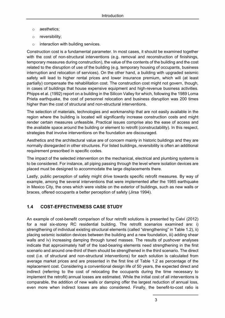
An example of cost-benefit comparison of four retrofit solutions is presented by Calvi (2012) for a real six-storey RC residential building. The retrofit scenarios examined are: i) strengthening of individual existing structural elements (called “strengthening” in Table 1.2), ii) placing seismic isolation devices between the building and a new foundation, iii) adding shear walls and iv) increasing damping through tuned masses. The results of pushover analyses indicate that approximately half of the load-bearing elements need strengthening in the first scenario and around one-third of them should be strengthened in the third scenario. The direct cost (i.e. of structural and non-structural interventions) for each solution is calculated from average market prices and are presented in the first line of Table 1.2 as percentage of the replacement cost. Considering a conventional design life of 50 years, the expected direct and indirect (referring to the cost of relocating the occupants during the time necessary to implement the retrofit) annual losses are estimated. While the initial cost of all interventions is comparable, the addition of new walls or damping offer the largest reduction of annual loss, even more when indirect losses are also considered. Finally, the benefit-to-cost ratio is
Introduction
4
calculated by dividing the reduction in near present value of expected annual loss over the 50 years of service life by the initial cost of the retrofit. It is noted that while seismic isolation and increase of damping have practically the same initial cost, the values reported in the two last rows of Table 1.2 show that the second solution is much more cost-efficient, as it results in a higher reduction of loss. This example illustrates the procedure to follow for cost-benefit analysis and needs to be adapted to the specific building and local conditions. For instance, in many countries the cost of adding new walls will probably be significantly lower than the introduction of isolation devices between new foundation elements and the original structure.
Table 1.2 Initial cost, expected annual loss and benefit-to-cost ratio of different retrofit solutions for a six-storey residential building (Calvi 2012)
Type of intervention
None (existing) Strengthening Isolation Shear walls Damping
Initial cost - 16.0 22.0 24.0 22.2
Annual loss* 1.70 / 2.66 1.37 / 1.81 1.20 / 1.41 0.79 / 1.06 0.84 / 1.07
Benefit/cost* - 1.04 / 2.66 1.16 / 2.85 1.91 / 3.34 1.96 / 3.58
* direct loss / total (direct and indirect) loss
1.5 INCREMENTAL SEISMIC REHABILITATION
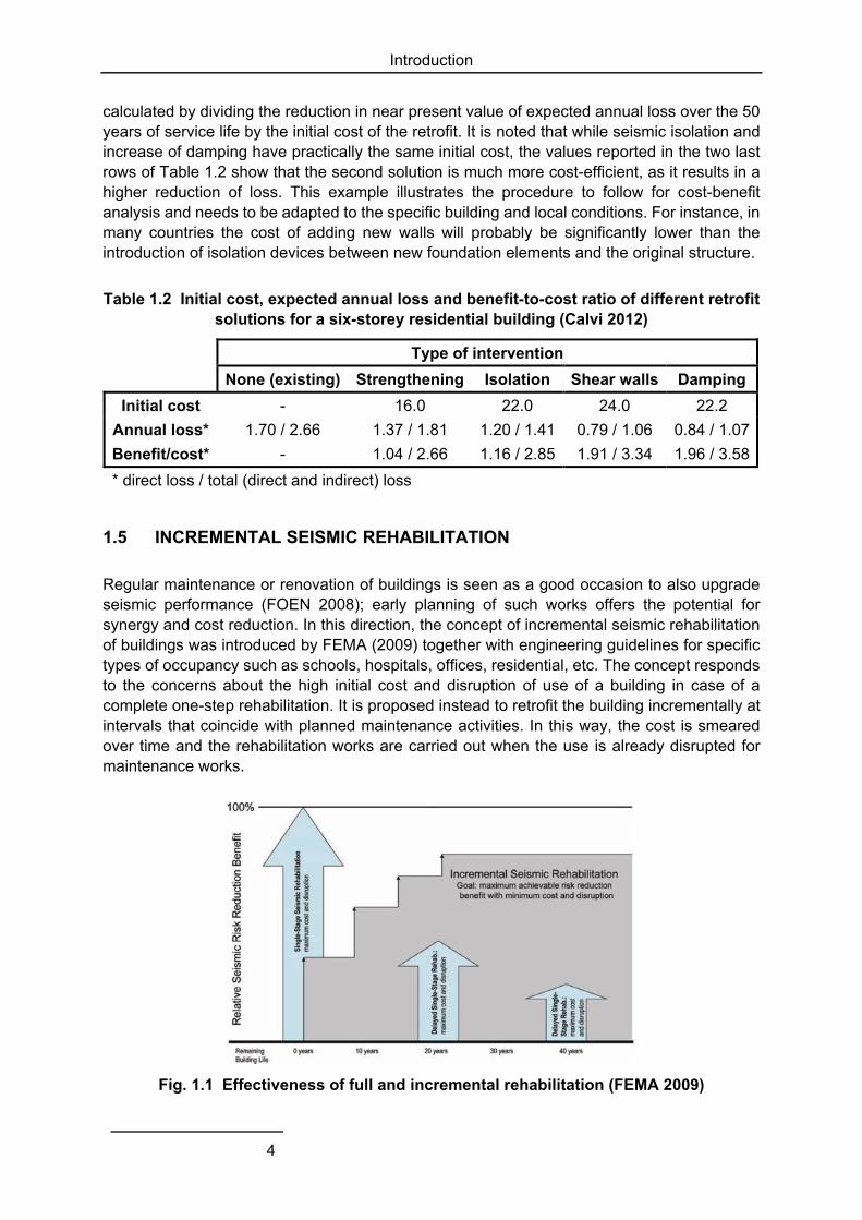
Regular maintenance or renovation of buildings is seen as a good occasion to also upgrade seismic performance (FOEN 2008); early planning of such works offers the potential for synergy and cost reduction. In this direction, the concept of incremental seismic rehabilitation of buildings was introduced by FEMA (2009) together with engineering guidelines for specific types of occupancy such as schools, hospitals, offices, residential, etc. The concept responds to the concerns about the high initial cost and disruption of use of a building in case of a complete one-step rehabilitation. It is proposed instead to retrofit the building incrementally at intervals that coincide with planned maintenance activities. In this way, the cost is smeared over time and the rehabilitation works are carried out when the use is already disrupted for maintenance works.
Fig. 1.1 Effectiveness of full and incremental rehabilitation (FEMA 2009)
Introduction
5
The concept is illustrated in Fig. 1.1, where full rehabilitation at t = 0 is taken as the benchmark for seismic risk reduction. In a cost-benefit framework of analysis, the expected annual loss for the remaining service life of the building is calculated and its reduction due to rehabilitation at different times in the future is discounted to a net present value. The benefit of a full rehabilitation is obviously reduced as the retrofit is implemented later in time, as indicated in Fig. 1.1 by the arrows at 0, 20 and 40 years. On the other hand, incremental seismic rehabilitation (e.g. in four steps during 20 years, as shown in Fig. 1.1) will produce a higher benefit than full rehabilitation executed at the end of the same period. The benefit will be nearly as much as that of one-step rehabilitation at t = 0. Fig. 1.1 serves to compare the alternative solutions; absolute values of risk reduction will depend on the specific building and rehabilitation strategies.
1.6 SELECTIVE WEAKENING
An alternative method for reducing the demand on a structure is to reduce the strength of certain elements or to modify the hierarchy of failure modes through selective removal of material (FEMA 2000, fib 2003). The selective weakening method proposed by Ireland et al. (2006) consists in reducing the strength and/or stiffness of selected elements, aiming to avoid undesired failure modes and to change the global inelastic mechanism to one that complies with capacity design, i.e. a strong column – weak beam system. Full selective weakening refers i) to the case where it is necessary to retrofit some elements with insufficient strength and/or deformation capacity for the new mechanism, or ii) to improvement of the performance of the weakened members in terms of energy dissipation and re-centring capacity. Reduction of stiffness will entail lengthening of the period of vibration of the structure with the favourable effect of reduced forces and the unfavourable one of increased displacement demand, compared to the as-built structure. Displacement demand may be somehow contained by the higher levels of damping associated with the improved energy dissipation capacity of the retrofitted structure. An additional advantage is that the strength of members can be tailored to the capacity of the foundation, thus overcoming the cumbersome interventions there.
Further to the conceptual development, the method has been experimentally assessed for single shear walls (see details in Section 4.2) and for frame structures. Full selective weakening was implemented in a scaled specimen of a four-storey 3×1-bay frame structure by cutting the slab reinforcement within the beam width and in its neighbourhood so as to reduce the beam’s negative moment resistance in conjunction with strengthening of shear-deficient joints by means of FRP wraps (Quintana Gallo et al. 2012). Shake-table tests demonstrated that this intervention was successful in relocating damage from shear failure of the joints in the as-built frame to flexural failure of the beams in the retrofitted one, but did not succeed in substantially reducing the storey drift.
Selective weakening is an intrusive method that may require upgrading some elements – possibly also the weakened ones – or implementing additional measures to improve the global deformation and energy dissipation capacity. This demands detailed analysis and workmanship beyond the current state of practice. Considering the above, it probably lags behind other more conventional methods in terms of cost-effectiveness.

Strengthening with steel bracings
7
2 Strengthening with steel bracings
2.1 OVERVIEW
A brief review of the state-of-practice and research on the topic of upgrading RC frame buildings by steel braces is presented in this Chapter. The addition of braces has been a popular method for the seismic strengthening of RC frames and it has been the subject of several investigations over the past decades. Steel bracings can be designed to provide stiffness, strength, ductility, energy dissipation, or any combination of these. Performance objectives ranging from drift control to collapse prevention can be achieved. Advantages and disadvantages of this retrofitting scheme are listed below (Badoux 1987, fib 2003, Thermou and Elnashai 2006).
Advantages:
o considerable increase of the lateral resistance;
o the level of strength and stiffness increase can be tuned relatively easily by the choice of the number and size of the braces;
o if adequately detailed (provided that early brittle failure of braces and their connections is prevented), satisfactory ductility and hysteretic behaviour can be obtained;
o the new system can be designed to carry the entire lateral loads, which is particularly advantageous if the frame has an unfavourable failure mechanism;
o adequate control over the flow of force (load path to effectively transfer forces from the elements to the foundations) and minimum local force concentration;
o minimal added weight to the structure;
o ability to accommodate openings;
o minimal disruption to the function of the buildings and its occupants (in the case of external bracing);
o ease of construction;
o minimum loss of living spaces and alteration of the architectural function of the building.
Disadvantages:
o difficult to control the interaction between new steel and existing concrete systems;
o not efficient for stiff concrete structures;
o sensitive to detailing of braces and connections against local buckling and post-buckling fracture;
o difficulty in achieving high-quality full-penetration welds on the construction site and installing epoxy-grouted fasteners.
The braces are directly fitted to the concrete frame (direct bracing) or attached to it through a steel frame (internal bracing), e.g. Kumar et al. (2009). The different types of bracing systems that have been proposed for the upgrading of existing concrete frames include:
Strengthening with steel bracings
8
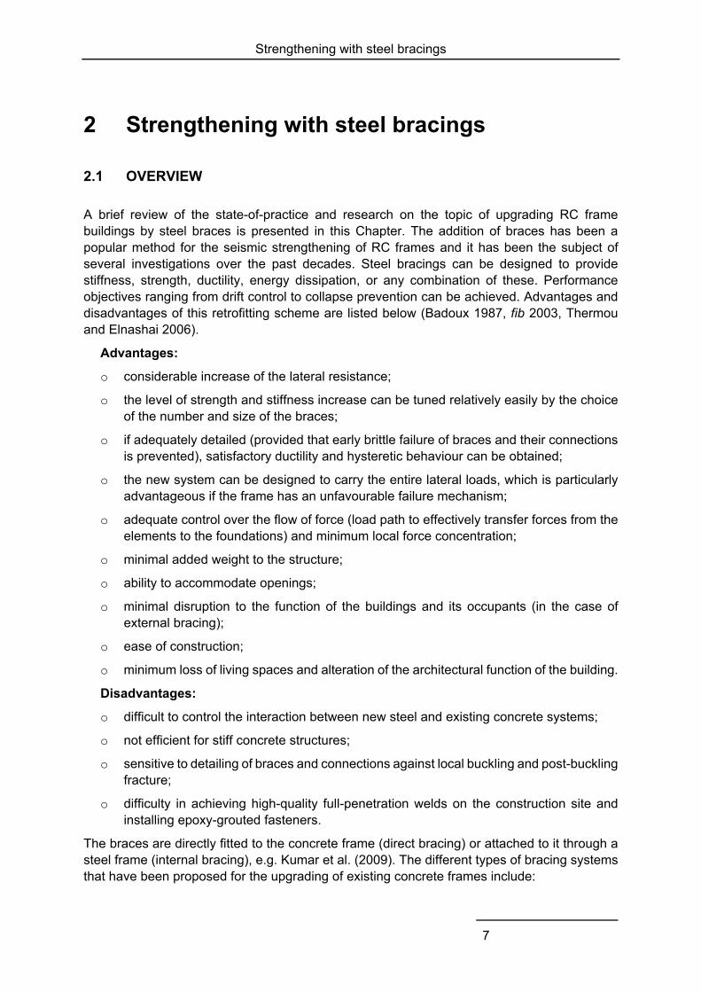
o concentric bracing (diagonal, X and V bracing), where the horizontal forces are mainly resisted by members subjected to axial loads (Fig. 2.1a);
o eccentric bracing, where the horizontal forces are mainly resisted by axially loaded members, but the eccentricity of the layout is such that energy can be dissipated in seismic links by means of either cyclic bending or cyclic shear (Fig. 2.1b);
o buckling-restrained bracing, in which global buckling is inhibited by an appropriate system (Fig. 2.1c);
o post-tensioned bracing.
a) concentric bracing b) eccentric bracing
c) buckling restrained bracing (Tsai et al. 2004)
Fig. 2.1 Different types of bracing systems
2.2 CONCENTRIC STEEL BRACING
Concentric bracing systems are the most widely used for retrofitting concrete frames. They contribute to the lateral-load resistance of the structure through the horizontal projection of the axial force (mainly axial tension) developing in their inclined members. Appropriate concentric bracing systems (Fig. 2.1a) are those with:
o diagonal bracings, in which there is a single diagonal per braced bay of the frame;
o X (or cross-diagonal) bracings, with braces along both diagonals of a braced bay;
o V or inverted V bracings (termed chevron bracings in the USA), in which a pair of inclined braces is connected to a point near or at the mid-span of a horizontal member (beam or slab) of a bay of the frame.
K bracings, in which the inclined braces are connected to a point within the clear height of a column should not be used, because the column may fail in shear when the high axial force of the brace is transferred as a horizontal force to a column with reduced height.
Strengthening with steel bracings
9
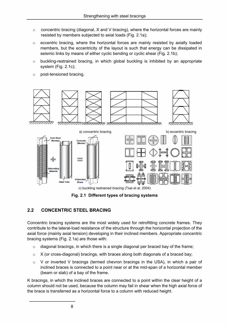
Maheri et al. (2003) proposed a direct connection between the bracing and the RC frame and performed pushover tests on 1/3-scaled models of a frame with direct X and knee braces (Fig. 2.2). In total, six specimens were constructed: two unbraced (F1 and F2), two X-braced (FB1 and FB2) and two knee-braced (FK1 and FK2) frames. The results shown in Table 2.1 and based on an elastic-perfectly plastic approximation of the experimental force-displacement curve, indicated that when a ductile frame was braced, in return for the increase in strength (up to 3.5 times) and stiffness (up to 2.5 times), ductility and Fe/Fy (i.e. the ratio of the elastic force at ultimate displacement to the yield strength, taken here as a measure of the reserve strength of the structure) were reduced up to twice, particularly for the X-braced frames. The knee-braced frames exhibited larger displacement ductility than the X-braced frames. Compared to the X-braced frames, knee-braced specimens offered a higher improvement of the overall seismic performance, regarding load capacity, stiffness and ductility. The ratio of yield strength of the bilinear curve, Fy, to the actual yield strength, Fs, is used as a measure of dissipated energy and shows that X braces provide a higher increase of energy dissipation capacity than the knee braces.
Fig. 2.2 Schematic view of X (left) and knee (right) bracing system
Table 2.1 Response parameters of the frames tested by Maheri et al. (2003)
Specimen F (kN) K (kN/m) uy (mm) uu (mm) µu Fe/Fy Fy/Fs
F1 34.0 2340 3.47 14.53 4.19 4.18 2.89
F2 35.0 2201 3.34 15.90 4.76 4.76 2.65
FB1 124.0 5585 8.18 22.20 2.71 2.71 1.57
FB2 119.0 5650 8.00 21.06 2.63 2.63 1.56
FK1 88.0 4821 6.49 18.25 2.81 2.81 2.53
FK2 77.0 4277 5.35 18.00 3.36 3.36 2.18
F: ultimate load capacity K: secant stiffness uy: yield displacement uu: ultimate displacement µu: displacement ductility
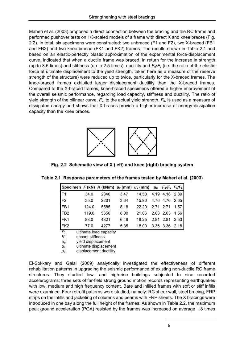
El-Sokkary and Galal (2009) analytically investigated the effectiveness of different rehabilitation patterns in upgrading the seismic performance of existing non-ductile RC frame structures. They studied low- and high-rise buildings subjected to nine recorded accelerograms: three sets of far-field strong ground motion records representing earthquakes with low, medium and high frequency content. Bare and infilled frames with soft or stiff infills were examined. Four retrofit patterns were studied, namely: RC shear wall, steel bracing, FRP strips on the infills and jacketing of columns and beams with FRP sheets. The X bracings were introduced in one bay along the full height of the frames. As shown in Table 2.2, the maximum peak ground acceleration (PGA) resisted by the frames was increased on average 1.8 times
Strengthening with steel bracings
10
for the five-storey frame and 1.2 times for the 15-storey frame. Retrofitting resulted in increased stiffness and higher shear resistance (on average 2.5 times). A reduction of maximum storey drifts of about 20 % was observed for the 15-storey braced building, compared to the as-built one. The dissipated energy was also increased, for both low- and high-rise buildings, particularly for the frames with soft masonry infills. The numerical analyses confirmed also that strengthening all frames of a building will provide higher increase (not proportional) of the shear resistance and energy-dissipation capacity, compared to strengthening half of the frames, and similar decrease in deformation demand.
Table 2.2 Performance parameters (average value of nine ground motions) of as-built and braced frames (El-Sokkary and Galal 2009)
No. of
storeys Bare frame Soft infill Stiff infill
As-built Braced As-built Braced As-built Braced
Maximum PGA (g) 5 15
0.40 0.79
0.74 0.73
0.58 0.94
1.02 1.14
0.47 0.73
0.81 0.89
Maximum storey drift (%) 5 15
0.96 1.16
1.00 0.83
1.09 1.16
1.03 1.04
0.67 1.00
0.75 0.86
Maximum storey shear / total structure weight
5 15
0.09 0.07
0.45 0.17
0.21 0.11
0.56 0.29
0.18 0.09
0.50 0.24
Dissipated energy (kNm) 5 15
82 518
499 824
285 1177
1053 2650
608 747
805 1618
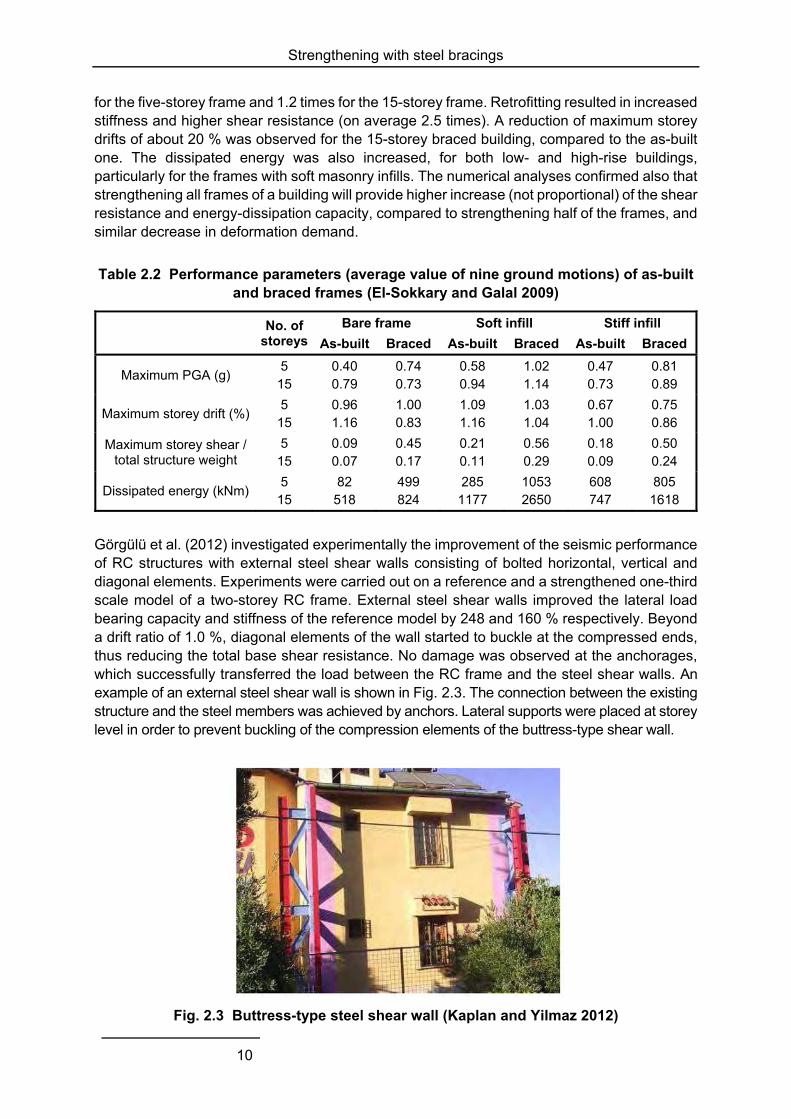
Görgülü et al. (2012) investigated experimentally the improvement of the seismic performance of RC structures with external steel shear walls consisting of bolted horizontal, vertical and diagonal elements. Experiments were carried out on a reference and a strengthened one-third scale model of a two-storey RC frame. External steel shear walls improved the lateral load bearing capacity and stiffness of the reference model by 248 and 160 % respectively. Beyond a drift ratio of 1.0 %, diagonal elements of the wall started to buckle at the compressed ends, thus reducing the total base shear resistance. No damage was observed at the anchorages, which successfully transferred the load between the RC frame and the steel shear walls. An example of an external steel shear wall is shown in Fig. 2.3. The connection between the existing structure and the steel members was achieved by anchors. Lateral supports were placed at storey level in order to prevent buckling of the compression elements of the buttress-type shear wall.
Fig. 2.3 Buttress-type steel shear wall (Kaplan and Yilmaz 2012)
Strengthening with steel bracings
11
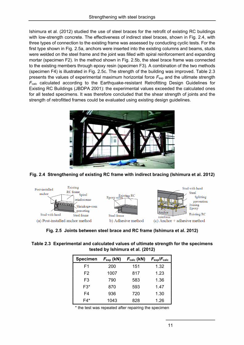
Ishimura et al. (2012) studied the use of steel braces for the retrofit of existing RC buildings with low-strength concrete. The effectiveness of indirect steel braces, shown in Fig. 2.4, with three types of connection to the existing frame was assessed by conducting cyclic tests. For the first type shown in Fig. 2.5a, anchors were inserted into the existing columns and beams, studs were welded on the steel frame and the joint was filled with spiral reinforcement and expanding mortar (specimen F2). In the method shown in Fig. 2.5b, the steel brace frame was connected to the existing members through epoxy resin (specimen F3). A combination of the two methods (specimen F4) is illustrated in Fig. 2.5c. The strength of the building was improved. Table 2.3 presents the values of experimental maximum horizontal force Fexp and the ultimate strength Fcalc calculated according to the Earthquake-resistant Retrofitting Design Guidelines for Existing RC Buildings (JBDPA 2001): the experimental values exceeded the calculated ones for all tested specimens. It was therefore concluded that the shear strength of joints and the strength of retrofitted frames could be evaluated using existing design guidelines.
Fig. 2.4 Strengthening of existing RC frame with indirect bracing (Ishimura et al. 2012)
Fig. 2.5 Joints between steel brace and RC frame (Ishimura et al. 2012)
Table 2.3 Experimental and calculated values of ultimate strength for the specimens tested by Ishimura et al. (2012)
Specimen Fexp (kN) Fcalc (kN) Fexp/Fcalc
F1 200 151 1.32
F2 1007 817 1.23
F3 790 583 1.36
F3* 870 593 1.47
F4 936 720 1.30
F4* 1043 828 1.26
* the test was repeated after repairing the specimen
Strengthening with steel bracings
12
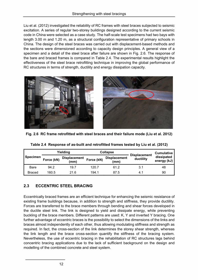
Liu et al. (2012) investigated the reliability of RC frames with steel braces subjected to seismic excitation. A series of regular two-storey buildings designed according to the current seismic code in China were selected as a case study. The half-scale test specimens had two bays with length 3.00 m and 1.20 m, as a structural configuration representative of primary schools in China. The design of the steel braces was carried out with displacement-based methods and the sections were dimensioned according to capacity design principles. A general view of a specimen and a detail of the steel brace after failure are shown in Fig. 2.6. The response of the bare and braced frames is compared in Table 2.4. The experimental results highlight the effectiveness of the steel brace retrofitting technique in improving the global performance of RC structures in terms of strength, ductility and energy dissipation capacity.
Fig. 2.6 RC frame retrofitted with steel braces and their failure mode (Liu et al. 2012)
Table 2.4 Response of as-built and retrofitted frames tested by Liu et al. (2012)
Specimen
Yielding Collapse Displacement
ductility
Cumulative dissipated energy (kJ)Force (kN)
Displacement(mm)
Force (kN)Displacement
(mm)
Bare 94.2 19.7 120.7 61.2 3.1 48
Braced 160.5 21.6 194.1 87.5 4.1 90
2.3 ECCENTRIC STEEL BRACING
Eccentrically braced frames are an efficient technique for enhancing the seismic resistance of existing frame buildings because, in addition to strength and stiffness, they provide ductility. Forces are transferred to the brace members through bending and shear forces developed in the ductile steel link. The link is designed to yield and dissipate energy, while preventing buckling of the brace members. Different patterns are used: K, Y and inverted Y bracing. One further advantage of eccentric braces is the possibility to select the dimensions of the links and braces almost independently of each other, thus allowing modulating stiffness and strength as required. In fact, the cross-section of the link determines the storey shear strength, whereas the link length and the brace cross-section quantify the stiffness of the bracing system. Nevertheless, the use of eccentric bracing in the rehabilitation of RC structures lags behind concentric bracing applications due to the lack of sufficient background on the design and modelling of the combined concrete and steel system.
Strengthening with steel bracings
13
Ghobarah and Abou Elfath (2001) performed time-history and pushover analyses to evaluate the effectiveness of rehabilitating a three-storey five-bay RC building with concentric V bracing (specimen V1) and eccentric inverted Y bracing (specimens E1 and E2). The same braces and shear links were used in specimens E1 and E2, but with a different distribution in height. The lateral load capacity of the rehabilitated building was 1.7, 1.6 and 1.9 times the load-carrying capacity of the existing one, respectively for the three cases. The ratio between the stiffness of buildings V1, E1 and E2 with respect to that of the existing building were 4.6, 2.8 and 3.0, respectively. The mean values (among the 12 earthquake records) of deformation and damage indices in the buildings with eccentric bracings were significantly lower than in the building with concentric bracing. For example, at PGA = 0.50g, the ratios of storey drift and the damage index of case V1 to those of case E1 were 1.23 and 1.20, respectively. The distribution of braces over the height was found to have a significant effect on the plastic mechanism and it was suggested that their strength should provide a uniform distribution of storey drift.
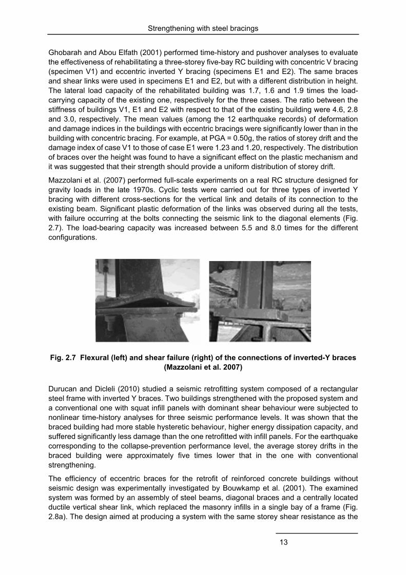
Mazzolani et al. (2007) performed full-scale experiments on a real RC structure designed for gravity loads in the late 1970s. Cyclic tests were carried out for three types of inverted Y bracing with different cross-sections for the vertical link and details of its connection to the existing beam. Significant plastic deformation of the links was observed during all the tests, with failure occurring at the bolts connecting the seismic link to the diagonal elements (Fig. 2.7). The load-bearing capacity was increased between 5.5 and 8.0 times for the different configurations.
Fig. 2.7 Flexural (left) and shear failure (right) of the connections of inverted-Y braces (Mazzolani et al. 2007)
Durucan and Dicleli (2010) studied a seismic retrofitting system composed of a rectangular steel frame with inverted Y braces. Two buildings strengthened with the proposed system and a conventional one with squat infill panels with dominant shear behaviour were subjected to nonlinear time-history analyses for three seismic performance levels. It was shown that the braced building had more stable hysteretic behaviour, higher energy dissipation capacity, and suffered significantly less damage than the one retrofitted with infill panels. For the earthquake corresponding to the collapse-prevention performance level, the average storey drifts in the braced building were approximately five times lower that in the one with conventional strengthening.
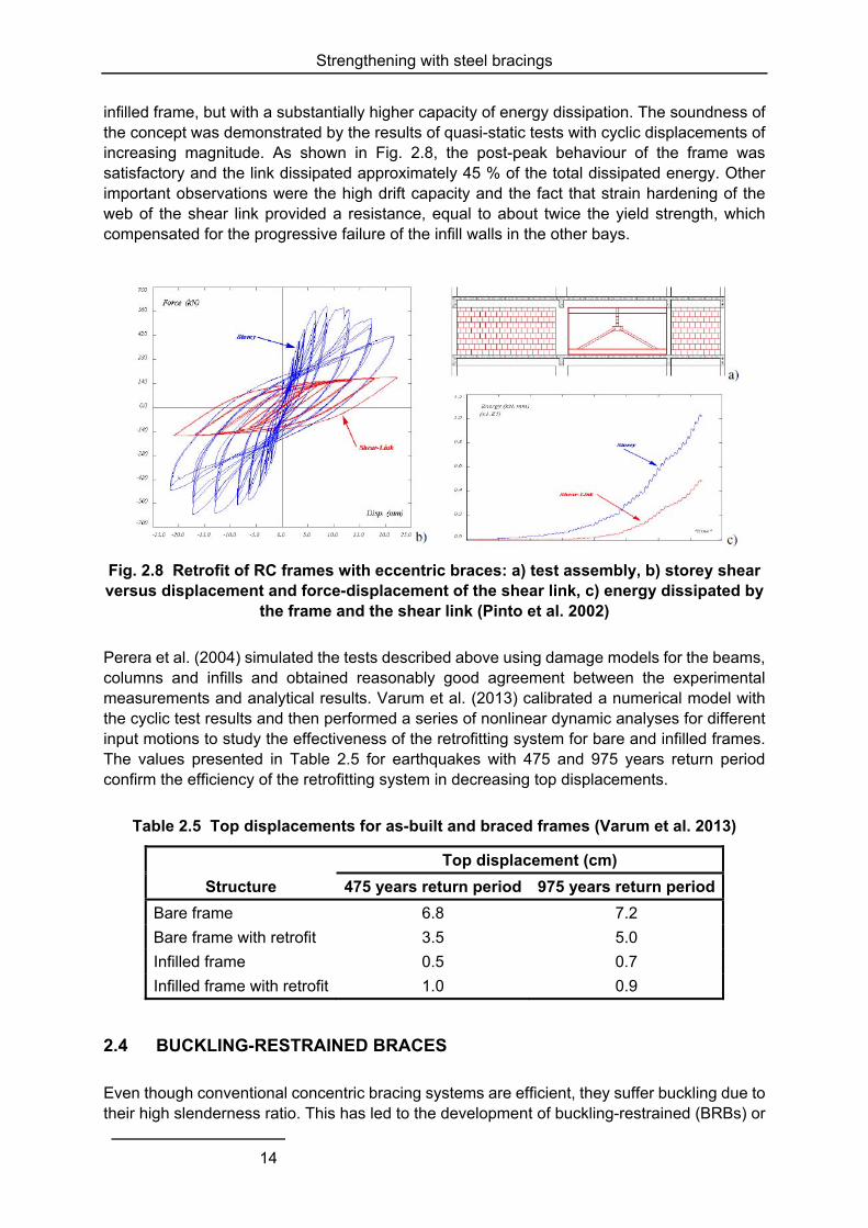
The efficiency of eccentric braces for the retrofit of reinforced concrete buildings without seismic design was experimentally investigated by Bouwkamp et al. (2001). The examined system was formed by an assembly of steel beams, diagonal braces and a centrally located ductile vertical shear link, which replaced the masonry infills in a single bay of a frame (Fig. 2.8a). The design aimed at producing a system with the same storey shear resistance as the
Strengthening with steel bracings
14
infilled frame, but with a substantially higher capacity of energy dissipation. The soundness of the concept was demonstrated by the results of quasi-static tests with cyclic displacements of increasing magnitude. As shown in Fig. 2.8, the post-peak behaviour of the frame was satisfactory and the link dissipated approximately 45 % of the total dissipated energy. Other important observations were the high drift capacity and the fact that strain hardening of the web of the shear link provided a resistance, equal to about twice the yield strength, which compensated for the progressive failure of the infill walls in the other bays.
Fig. 2.8 Retrofit of RC frames with eccentric braces: a) test assembly, b) storey shear versus displacement and force-displacement of the shear link, c) energy dissipated by
the frame and the shear link (Pinto et al. 2002)
Perera et al. (2004) simulated the tests described above using damage models for the beams, columns and infills and obtained reasonably good agreement between the experimental measurements and analytical results. Varum et al. (2013) calibrated a numerical model with the cyclic test results and then performed a series of nonlinear dynamic analyses for different input motions to study the effectiveness of the retrofitting system for bare and infilled frames. The values presented in Table 2.5 for earthquakes with 475 and 975 years return period confirm the efficiency of the retrofitting system in decreasing top displacements.
Table 2.5 Top displacements for as-built and braced frames (Varum et al. 2013)
Structure
Top displacement (cm)
475 years return period 975 years return period
Bare frame 6.8 7.2
Bare frame with retrofit 3.5 5.0
Infilled frame 0.5 0.7
Infilled frame with retrofit 1.0 0.9
2.4 BUCKLING-RESTRAINED BRACES
Even though conventional concentric bracing systems are efficient, they suffer buckling due to their high slenderness ratio. This has led to the development of buckling-restrained (BRBs) or
Strengthening with steel bracings
15
unbonded braces, in which a steel core element (cross-shape or flat bar) is encased into a steel tube (called also the buckling-restraining element) and is confined by an unbonding material like concrete mortar, rubber, silicon, vinyl, etc. The core element is designed to resist the axial tension or compression force without local or global flexural buckling.
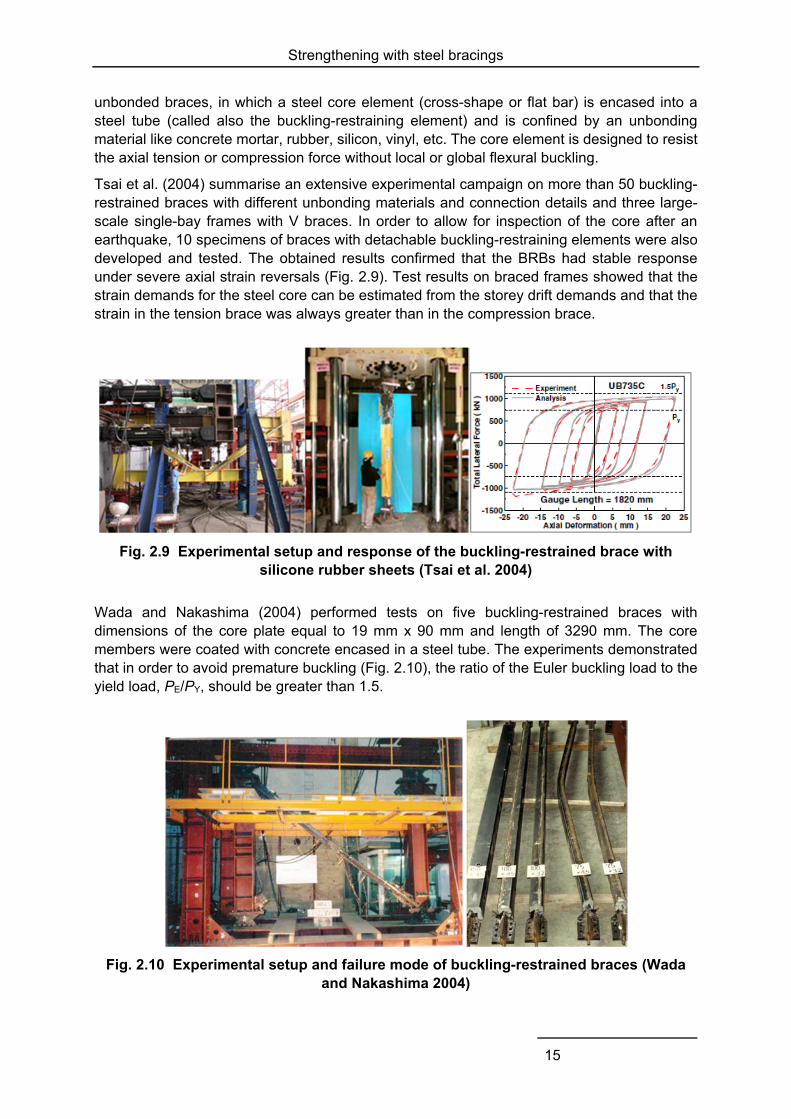
Tsai et al. (2004) summarise an extensive experimental campaign on more than 50 buckling-restrained braces with different unbonding materials and connection details and three large-scale single-bay frames with V braces. In order to allow for inspection of the core after an earthquake, 10 specimens of braces with detachable buckling-restraining elements were also developed and tested. The obtained results confirmed that the BRBs had stable response under severe axial strain reversals (Fig. 2.9). Test results on braced frames showed that the strain demands for the steel core can be estimated from the storey drift demands and that the strain in the tension brace was always greater than in the compression brace.
Fig. 2.9 Experimental setup and response of the buckling-restrained brace with silicone rubber sheets (Tsai et al. 2004)
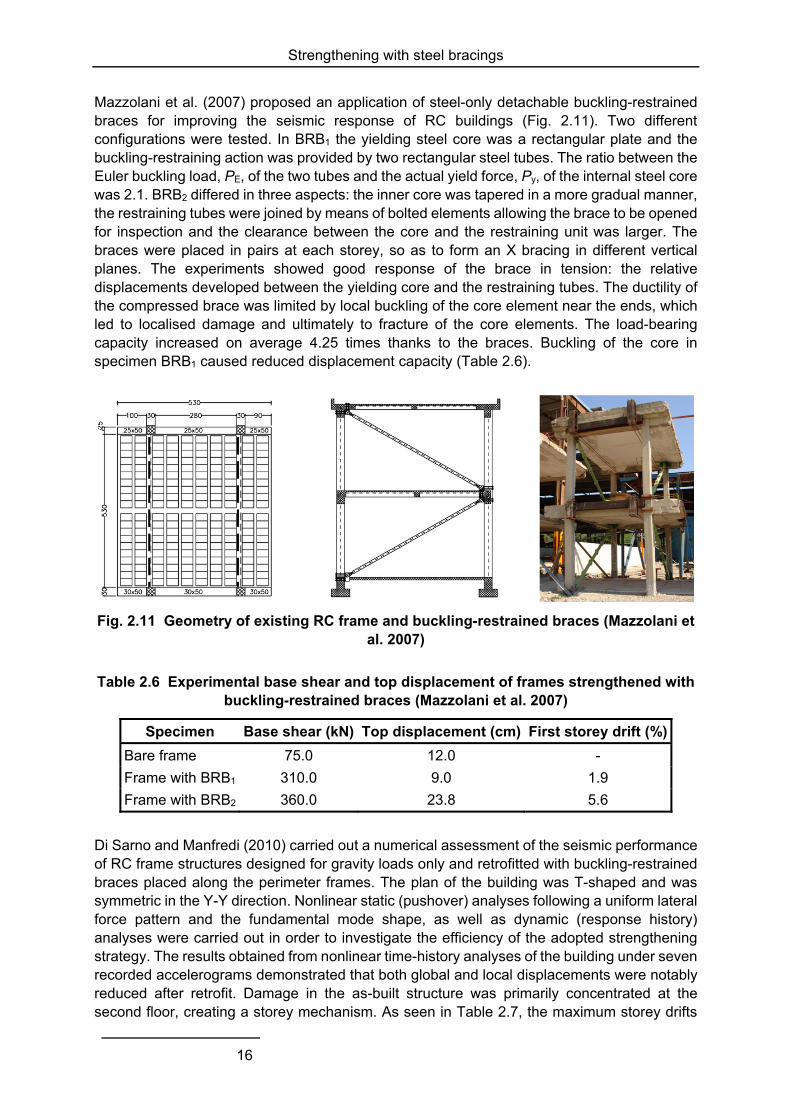
Wada and Nakashima (2004) performed tests on five buckling-restrained braces with dimensions of the core plate equal to 19 mm x 90 mm and length of 3290 mm. The core members were coated with concrete encased in a steel tube. The experiments demonstrated that in order to avoid premature buckling (Fig. 2.10), the ratio of the Euler buckling load to the yield load, PE/PY, should be greater than 1.5.
Fig. 2.10 Experimental setup and failure mode of buckling-restrained braces (Wada and Nakashima 2004)
Strengthening with steel bracings
16
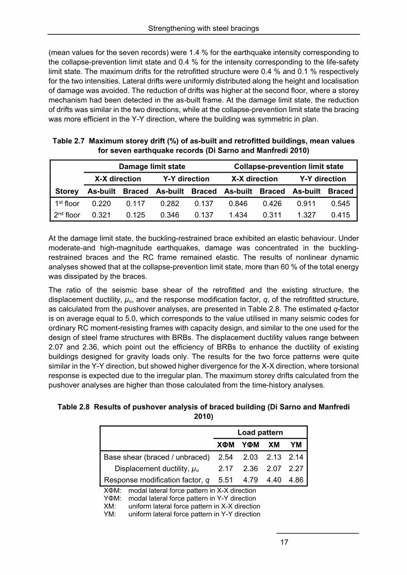
Mazzolani et al. (2007) proposed an application of steel-only detachable buckling-restrained braces for improving the seismic response of RC buildings (Fig. 2.11). Two different configurations were tested. In BRB1 the yielding steel core was a rectangular plate and the buckling-restraining action was provided by two rectangular steel tubes. The ratio between the Euler buckling load, PE, of the two tubes and the actual yield force, Py, of the internal steel core was 2.1. BRB2 differed in three aspects: the inner core was tapered in a more gradual manner, the restraining tubes were joined by means of bolted elements allowing the brace to be opened for inspection and the clearance between the core and the restraining unit was larger. The braces were placed in pairs at each storey, so as to form an X bracing in different vertical planes. The experiments showed good response of the brace in tension: the relative displacements developed between the yielding core and the restraining tubes. The ductility of the compressed brace was limited by local buckling of the core element near the ends, which led to localised damage and ultimately to fracture of the core elements. The load-bearing capacity increased on average 4.25 times thanks to the braces. Buckling of the core in specimen BRB1 caused reduced displacement capacity (Table 2.6).
Fig. 2.11 Geometry of existing RC frame and buckling-restrained braces (Mazzolani et al. 2007)
Table 2.6 Experimental base shear and top displacement of frames strengthened with buckling-restrained braces (Mazzolani et al. 2007)
Specimen Base shear (kN) Top displacement (cm) First storey drift (%)
Bare frame 75.0 12.0 -
Frame with BRB1 310.0 9.0 1.9
Frame with BRB2 360.0 23.8 5.6
Di Sarno and Manfredi (2010) carried out a numerical assessment of the seismic performance of RC frame structures designed for gravity loads only and retrofitted with buckling-restrained braces placed along the perimeter frames. The plan of the building was T-shaped and was symmetric in the Y-Y direction. Nonlinear static (pushover) analyses following a uniform lateral force pattern and the fundamental mode shape, as well as dynamic (response history) analyses were carried out in order to investigate the efficiency of the adopted strengthening strategy. The results obtained from nonlinear time-history analyses of the building under seven recorded accelerograms demonstrated that both global and local displacements were notably reduced after retrofit. Damage in the as-built structure was primarily concentrated at the second floor, creating a storey mechanism. As seen in Table 2.7, the maximum storey drifts
Strengthening with steel bracings
17
(mean values for the seven records) were 1.4 % for the earthquake intensity corresponding to the collapse-prevention limit state and 0.4 % for the intensity corresponding to the life-safety limit state. The maximum drifts for the retrofitted structure were 0.4 % and 0.1 % respectively for the two intensities. Lateral drifts were uniformly distributed along the height and localisation of damage was avoided. The reduction of drifts was higher at the second floor, where a storey mechanism had been detected in the as-built frame. At the damage limit state, the reduction of drifts was similar in the two directions, while at the collapse-prevention limit state the bracing was more efficient in the Y-Y direction, where the building was symmetric in plan.
Table 2.7 Maximum storey drift (%) of as-built and retrofitted buildings, mean values for seven earthquake records (Di Sarno and Manfredi 2010)
Damage limit state Collapse-prevention limit state
X-X direction Y-Y direction X-X direction Y-Y direction
Storey As-built Braced As-built Braced As-built Braced As-built Braced
1st floor 0.220 0.117 0.282 0.137 0.846 0.426 0.911 0.545
2nd floor 0.321 0.125 0.346 0.137 1.434 0.311 1.327 0.415
At the damage limit state, the buckling-restrained brace exhibited an elastic behaviour. Under moderate-and high-magnitude earthquakes, damage was concentrated in the buckling-restrained braces and the RC frame remained elastic. The results of nonlinear dynamic analyses showed that at the collapse-prevention limit state, more than 60 % of the total energy was dissipated by the braces.
The ratio of the seismic base shear of the retrofitted and the existing structure, the displacement ductility, µu, and the response modification factor, q, of the retrofitted structure, as calculated from the pushover analyses, are presented in Table 2.8. The estimated q-factor is on average equal to 5.0, which corresponds to the value utilised in many seismic codes for ordinary RC moment-resisting frames with capacity design, and similar to the one used for the design of steel frame structures with BRBs. The displacement ductility values range between 2.07 and 2.36, which point out the efficiency of BRBs to enhance the ductility of existing buildings designed for gravity loads only. The results for the two force patterns were quite similar in the Y-Y direction, but showed higher divergence for the X-X direction, where torsional response is expected due to the irregular plan. The maximum storey drifts calculated from the pushover analyses are higher than those calculated from the time-history analyses.
Table 2.8 Results of pushover analysis of braced building (Di Sarno and Manfredi 2010)
Load pattern
XΦM YΦM XM YM
Base shear (braced / unbraced) 2.54 2.03 2.13 2.14
Displacement ductility, µu 2.17 2.36 2.07 2.27
Response modification factor, q 5.51 4.79 4.40 4.86 XΦM: modal lateral force pattern in X-X direction YΦM: modal lateral force pattern in Y-Y direction XM: uniform lateral force pattern in X-X direction YM: uniform lateral force pattern in Y-Y direction
Strengthening with steel bracings
18
Mahrenholtz et al. (2014) performed cyclic tests to investigate the seismic performance of reinforced concrete frames retrofitted with buckling-restrained braces directly connected to the RC structure through anchors. The tests demonstrated the feasibility of the proposed retrofit method and showed that it increased strength and ductility to an adequate seismic performance level. Compared to the concrete frame alone, the dissipated energy was about five times higher and the lateral load capacity was about four times higher. Further investigations were recommended on different configurations, design assumptions and local buckling of the anchoring elements.
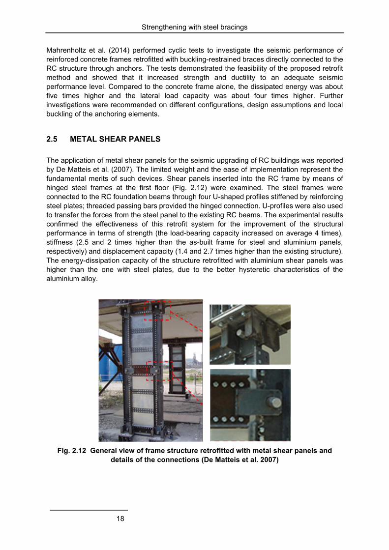
2.5 METAL SHEAR PANELS
The application of metal shear panels for the seismic upgrading of RC buildings was reported by De Matteis et al. (2007). The limited weight and the ease of implementation represent the fundamental merits of such devices. Shear panels inserted into the RC frame by means of hinged steel frames at the first floor (Fig. 2.12) were examined. The steel frames were connected to the RC foundation beams through four U-shaped profiles stiffened by reinforcing steel plates; threaded passing bars provided the hinged connection. U-profiles were also used to transfer the forces from the steel panel to the existing RC beams. The experimental results confirmed the effectiveness of this retrofit system for the improvement of the structural performance in terms of strength (the load-bearing capacity increased on average 4 times), stiffness (2.5 and 2 times higher than the as-built frame for steel and aluminium panels, respectively) and displacement capacity (1.4 and 2.7 times higher than the existing structure). The energy-dissipation capacity of the structure retrofitted with aluminium shear panels was higher than the one with steel plates, due to the better hysteretic characteristics of the aluminium alloy.
Fig. 2.12 General view of frame structure retrofitted with metal shear panels and details of the connections (De Matteis et al. 2007)
Strengthening with steel bracings
19
2.6 RETROFITTING WITH POST-TENSIONED CABLES
The use of post-tensioned steel cables in seismic rehabilitation is a relatively new technique that can be applied to low- and mid-rise frame buildings (fib 2003). Post-tensioned cables are used to eliminate the problems associated with buckling of conventional bracing systems and require minimal modifications of the original structure. They can be used in combination with other techniques, such as new shear walls and column jackets. Prestressed cables may be easily placed on the façades of buildings, extending over several storeys. They are made of strands enclosed in steel or PVC ducts with appropriate corrosion protection. Cables prestressed at high levels may yield and accumulate inelastic tensile strains that may reduce their effectiveness during a seismic event. Furthermore, they need to be re-tensioned as large time-dependent losses are expected after prestressing at high forces. Previous practical applications and research have proposed prestressing the cables at 20 to 75 % of their yield force. Pretensioning of the cables induces axial compression in the columns which may reduce their flexural ductility, particularly in mid- and high-rise buildings where axial forces due to permanent loads are already high.
2.7 SUMMARY
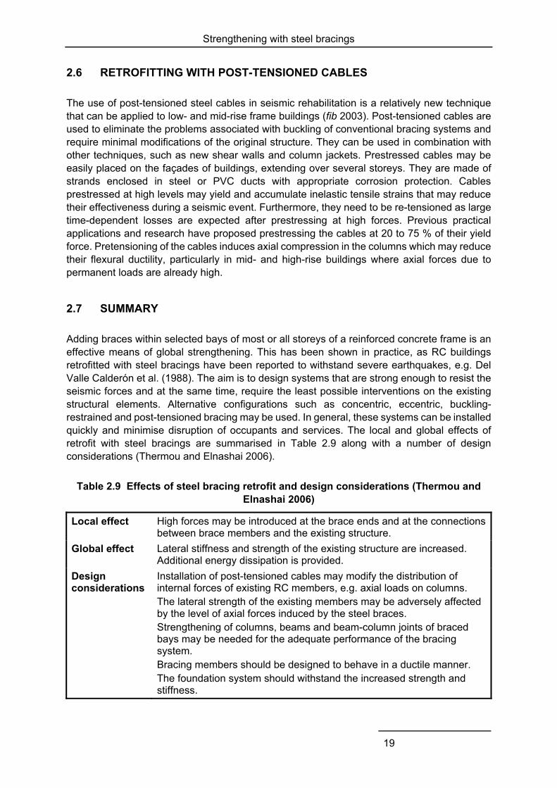
Adding braces within selected bays of most or all storeys of a reinforced concrete frame is an effective means of global strengthening. This has been shown in practice, as RC buildings retrofitted with steel bracings have been reported to withstand severe earthquakes, e.g. Del Valle Calderón et al. (1988). The aim is to design systems that are strong enough to resist the seismic forces and at the same time, require the least possible interventions on the existing structural elements. Alternative configurations such as concentric, eccentric, buckling-restrained and post-tensioned bracing may be used. In general, these systems can be installed quickly and minimise disruption of occupants and services. The local and global effects of retrofit with steel bracings are summarised in Table 2.9 along with a number of design considerations (Thermou and Elnashai 2006).
Table 2.9 Effects of steel bracing retrofit and design considerations (Thermou and Elnashai 2006)
Local effect High forces may be introduced at the brace ends and at the connections between brace members and the existing structure.
Global effect Lateral stiffness and strength of the existing structure are increased. Additional energy dissipation is provided.
Design considerations
Installation of post-tensioned cables may modify the distribution of internal forces of existing RC members, e.g. axial loads on columns. The lateral strength of the existing members may be adversely affected by the level of axial forces induced by the steel braces. Strengthening of columns, beams and beam-column joints of braced bays may be needed for the adequate performance of the bracing system. Bracing members should be designed to behave in a ductile manner. The foundation system should withstand the increased strength and stiffness.
Strengthening with steel bracings
20
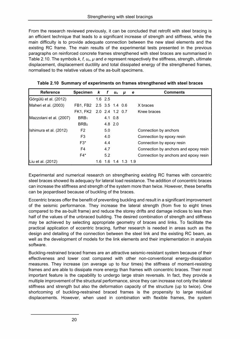
From the research reviewed previously, it can be concluded that retrofit with steel bracing is an efficient technique that leads to a significant increase of strength and stiffness, while the main difficulty is to provide adequate connection between the new steel elements and the existing RC frame. The main results of the experimental tests presented in the previous paragraphs on reinforced concrete frames strengthened with steel braces are summarised in Table 2.10. The symbols k, f, uu, µ and e represent respectively the stiffness, strength, ultimate displacement, displacement ductility and total dissipated energy of the strengthened frames, normalised to the relative values of the as-built specimens.
Table 2.10 Summary of experiments on frames strengthened with steel braces
Reference Specimen k f uu µ e Comments
Görgülü et al. (2012) 1.6 2.5
Maheri et al. (2003) FB1, FB2 2.5 3.5 1.4 0.6 X braces
FK1, FK2 2.0 2.4 1.2 0.7 Knee braces
Mazzolani et al. (2007) BRB1 4.1 0.8
BRB2 4.8 2.0
Ishimura et al. (2012) F2 5.0 Connection by anchors
F3 4.0 Connection by epoxy resin
F3* 4.4 Connection by epoxy resin
F4 4.7 Connection by anchors and epoxy resin
F4* 5.2 Connection by anchors and epoxy resin
Liu et al. (2012) 1.6 1.6 1.4 1.3 1.9
Experimental and numerical research on strengthening existing RC frames with concentric steel braces showed its adequacy for lateral load resistance. The addition of concentric braces can increase the stiffness and strength of the system more than twice. However, these benefits can be jeopardised because of buckling of the braces.
Eccentric braces offer the benefit of preventing buckling and result in a significant improvement of the seismic performance. They increase the lateral strength (from five to eight times compared to the as-built frame) and reduce the storey drifts and damage indices to less than half of the values of the unbraced building. The desired combination of strength and stiffness may be achieved by selecting appropriate geometry of braces and links. To facilitate the practical application of eccentric bracing, further research is needed in areas such as the design and detailing of the connection between the steel link and the existing RC beam, as well as the development of models for the link elements and their implementation in analysis software.
Buckling-restrained braced frames are an attractive seismic-resistant system because of their effectiveness and lower cost compared with other non-conventional energy-dissipation measures. They increase (on average up to four times) the stiffness of moment-resisting frames and are able to dissipate more energy than frames with concentric braces. Their most important feature is the capability to undergo large strain reversals. In fact, they provide a multiple improvement of the structural performance, since they can increase not only the lateral stiffness and strength but also the deformation capacity of the structure (up to twice). One shortcoming of buckling-restrained braced frames is the propensity to large residual displacements. However, when used in combination with flexible frames, the system
Strengthening with steel bracings
21
possesses significant post-yield stiffness and re-centring capacity (if the flexible frames are in the elastic range, the structure will return to its initial position after the braces are removed).
The use of metal shear panels is an innovative system, which deserves attention. Previous research is limited, but the obtained results point out their contribution in terms of strength and stiffness. Aluminium panels in particular, have been shown to increase significantly the energy dissipation capacity of existing RC frames. Further investigations are necessary in order to develop numerical models and design procedures.

Strengthening with infills
23
3 Strengthening with infills
3.1 OVERVIEW
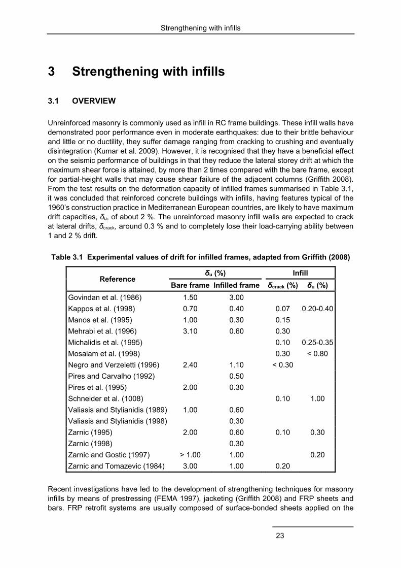
Unreinforced masonry is commonly used as infill in RC frame buildings. These infill walls have demonstrated poor performance even in moderate earthquakes: due to their brittle behaviour and little or no ductility, they suffer damage ranging from cracking to crushing and eventually disintegration (Kumar et al. 2009). However, it is recognised that they have a beneficial effect on the seismic performance of buildings in that they reduce the lateral storey drift at which the maximum shear force is attained, by more than 2 times compared with the bare frame, except for partial-height walls that may cause shear failure of the adjacent columns (Griffith 2008). From the test results on the deformation capacity of infilled frames summarised in Table 3.1, it was concluded that reinforced concrete buildings with infills, having features typical of the 1960’s construction practice in Mediterranean European countries, are likely to have maximum drift capacities, δu, of about 2 %. The unreinforced masonry infill walls are expected to crack at lateral drifts, δcrack, around 0.3 % and to completely lose their load-carrying ability between 1 and 2 % drift.
Table 3.1 Experimental values of drift for infilled frames, adapted from Griffith (2008)
Reference δu (%) Infill
Bare frame Infilled frame δcrack (%) δu (%)
Govindan et al. (1986) 1.50 3.00
Kappos et al. (1998) 0.70 0.40 0.07 0.20-0.40
Manos et al. (1995) 1.00 0.30 0.15
Mehrabi et al. (1996) 3.10 0.60 0.30
Michalidis et al. (1995) 0.10 0.25-0.35
Mosalam et al. (1998) 0.30 < 0.80
Negro and Verzeletti (1996) 2.40 1.10 < 0.30
Pires and Carvalho (1992) 0.50
Pires et al. (1995) 2.00 0.30
Schneider et al. (1008) 0.10 1.00
Valiasis and Stylianidis (1989) 1.00 0.60
Valiasis and Stylianidis (1998) 0.30
Zarnic (1995) 2.00 0.60 0.10 0.30
Zarnic (1998) 0.30
Zarnic and Gostic (1997) > 1.00 1.00 0.20
Zarnic and Tomazevic (1984) 3.00 1.00 0.20
Recent investigations have led to the development of strengthening techniques for masonry infills by means of prestressing (FEMA 1997), jacketing (Griffith 2008) and FRP sheets and bars. FRP retrofit systems are usually composed of surface-bonded sheets applied on the
Strengthening with infills
24
masonry walls and anchored on the reinforced concrete frame with an epoxy resin. Several studies have shown that this measure can increase the infill strength and delay cracking (Cunha et al. 2011). However, further research is needed regarding its efficiency in improving the global seismic behaviour of buildings (Kumar et al. 2009).
Another possibility is strengthening with infills composed of precast panels. These elements can be constructed rapidly and with high quality control. More important, they help to avoid the practical implications of cast-in-place walls, such as interference with occupants and functions of the building, long construction time and man power (Frosch et al. 1996).
3.2 STRENGTHENING BY MASONRY INFILLS
Lee and Woo (2002) investigated the effect of masonry infills on the seismic performance of low-rise RC frames without seismic detailing. For this purpose, a two-bay three-storey masonry-infilled RC frame was selected and a 1:5-scale model was constructed according to South Korean practice of non-seismic detailing. A series of earthquake simulation tests and a pushover test were performed on the models. Global response quantities measured during the earthquake simulation tests on the bare frame (BF), fully infilled frame (FIF) and partially infilled frame (PIF - same as the FIF specimen, except that masonry infills in the longer span were removed in all storeys) are summarised in Table 3.2. It can be seen that the drifts of the PIF were greater than those of the FIF under the same level of input ground motion. However, the maximum interstorey drift ratios of neither FIF nor PIF exceeded the value of 1.5 % allowed in the South Korean seismic code, even under TFT 04. The maximum base shear of FIF, PIF, and BF under TFT 012 were 32.0, 37.3, and 17.6 kN, respectively. These are 2.5 – 5.3 times the design base shear of the bare frame, which is equal to 7.03 kN according to the South Korean seismic code.
Table 3.2 Experimental results for bare and infilled frames (Lee and Woo 2002)
Test Maximum interstorey drift ratio (%) Base shear (kN)
BF FIF PIF BF FIF PIF
TFT_012 0.26 0.04 0.24 17.6 32.0 37.3
TFT_02 0.78 0.11 0.28 30.8 54.7 49.0
TFT_03 1.08 0.11 0.30 35.1 91.4 68.8
TFT_04 1.68 0.19 0.51 37.1 94.3 72.8
Test: Taft N21E component scaled accordingly to 0.12g (design earthquake in South Korea – 475 years return period), 0.2g (1000 years return period), 0.3g (2000 years return period) and 0.4g (severe earthquake in a high-seismicity region in the world)
Global response measures from the pushover static experimental tests on the bare and partially infilled frames are compared in Table 3.3. From this table, it can be seen that the actual (yielding) strength of PIF is 13.9 times the design base shear, 7.03 kN, with that of BF being 5.7 times. Generally, it can be observed that the masonry infills contribute to the increase in the global stiffness and strength of the structure, whereas they also result in the increase of earthquake inertia forces. The experimental results showed that the failure mode of the masonry-infilled frame was that of shear failure of the masonry infills due to the bed-joint sliding, while that of the bare frame appeared to be the soft-storey plastic mechanism at the
Strengthening with infills
25
first storey. The deformation capacity of the global structure remained almost the same regardless of the presence of the masonry infills.
Table 3.3 Results of pushover analysis of bare and partially-infilled frames (Lee and Woo 2002)
Bare frame (1) Partially-infilled frame (2) (2)/(1)
Ultimate strength 53.0kN 106.4 kN 2.00
Yielding strength 40.0 kN 98.0 kN 2.45
Yield drift at roof 20.0 mm (0.9 %)* 10.2 mm (0.5 %)* 0.51
Initial stiffness 2.0 kN/mm 9.6 kN/mm 4.80
Drift capacity 47.2 mm (2.13 %)* 43.1 mm (1.94 %)* 0.91
Displacement ductility 2.36 4.23 1.79
* The number in parentheses is the drift ratio expressed as percentage of the building height
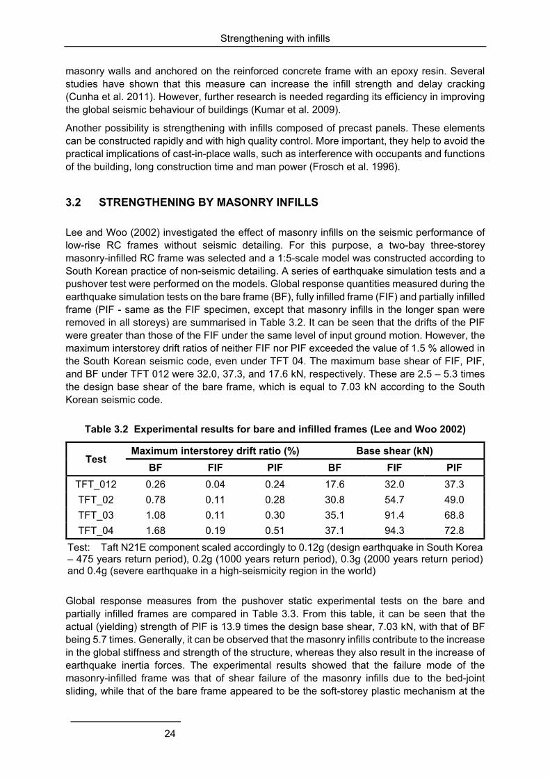
Pujol et al. (2008) carried out tests on a full-scale three-storey flat-slab structure under displacement reversals. A bare frame and a specimen with infill walls (Fig. 3.1) were tested. The walls increased the strength and stiffness of the bare frame by 100 and 500 % respectively. The strengthened specimen maintained its stiffness up to a global drift of 1.5 %. The results of numerical simulations were, overall, in good agreement with the experimental response, except for the ultimate displacement.
Fig. 3.1 Flat-slab structure strengthened with masonry infill walls (Pujol et al. 2008)
Alam et al. (2009) examined ferrocement overlays as a cost-effective method for strengthening existing infilled RC frames. Numerical results showed that the strength and stiffness of the as-built frame increased respectively 1.7 and 2.1 times. The authors developed a simple equation for estimating the lateral strength of masonry-infilled RC frames which gave reasonably accurate values, compared to the experimental ones.
Chung et al. (2011) proposed the retrofitting of existing buildings by adding sandwich columns on the masonry infill walls. The sandwich column is made up of two reinforced concrete parts
Strengthening with infills
26
that are constructed on the two sides of the partition wall and are connected through U-shaped stirrups crossing the infill. The feasibility of the technique was verified by tests performed on five full-scale specimens under cyclic loading in the out-of-plane direction. Strengthened specimens had more than twice the strength of their as-built counterparts and significant post-peak capacity. Compared to bare frames, infilled ones showed less degradation of strength. The analytical results for the lateral strength of the sandwich columns were conservative with respect to the experimental values.
3.3 FRP STRENGTHENING OF MASONRY INFILLS
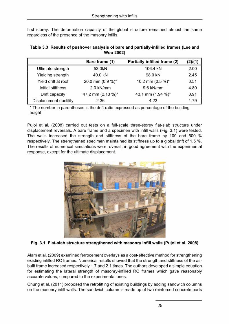
Erdem et al. (2004, 2006) examined the effectiveness of RC infills and masonry infills strengthened with FRP sheets for the enhancement of the strength and stiffness of two-storey three-bay frames. As seen in Fig. 3.2, the two techniques resulted in similar response until the peak force, but the specimen with masonry infills (S2 in Fig. 3.2) suffered a much more rapid degradation of strength than the one with RC infills (S1). The results of numerical simulation were sensitive to the chosen parameters, particularly for the specimen with FRP sheets applied on the masonry infill.
Fig. 3.2 Frame retrofitted by RC infilling (left) and force-displacement envelopes of as-built and retrofitted frames (right) tested by Erdem et al. (2004)
The structure studied by Erdem et al. (2006) was later tested using the pseudo-dynamic method and an accelerogram recorded during the 1999 Duzce earthquake (Kurt 2010). The frame was tested in as-built conditions and retrofitted by converting the central bay to a shear wall composed of masonry infills strengthened with FRP strips, precast concrete panels or RC infills. Among all specimens, the one with RC infills showed the highest enhancement of strength and stiffness and suffered the least damage. However, it experienced a rapid post-peak loss of resistance, whereas the other specimens managed to maintain the maximum strength for higher deformation demands.
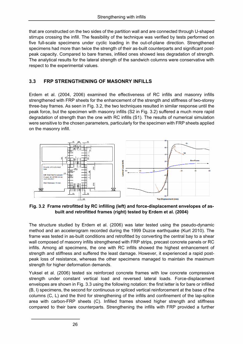
Yuksel et al. (2006) tested six reinforced concrete frames with low concrete compressive strength under constant vertical load and reversed lateral loads. Force-displacement envelopes are shown in Fig. 3.3 using the following notation: the first letter is for bare or infilled (B, I) specimens, the second for continuous or spliced vertical reinforcement at the base of the columns (C, L) and the third for strengthening of the infills and confinement of the lap-splice area with carbon-FRP sheets (C). Infilled frames showed higher strength and stiffness compared to their bare counterparts. Strengthening the infills with FRP provided a further
Strengthening with infills
27
increase of strength and no notable alteration of the stiffness. The addition of FRP strips modified the response of infills: crushing at the corners was prevented, diagonal cracking was distributed throughout the infill and despite the severe damage, collapse was avoided. It should be noted that due to the higher concrete compressive strength, the frame with spliced vertical reinforcement shows slightly bigger strength and stiffness compared to the one with continuous vertical reinforcement.
Fig. 3.3 Base shear versus displacement envelopes for bare and infilled frames and damage of infills strengthened with FRP (Yuksel et al. 2005)
Binici et al. (2007) investigated the use of FRP-strengthened infill walls as lateral load resisting elements and their effectiveness for the retrofit of seismic-deficient reinforced concrete frame buildings. Strengthened infills were connected to the RC frame through FRP anchors and aimed primarily at limiting deformations. Pushover analysis of a real mid-rise building strengthened with this technique showed an increase of strength by 100 to 150 % (in the two main directions of the building) with respect to the as-built conditions and a reduction of drift demands to less than 1 %. Numerical results for the Duzce earthquake showed also that the number of the building columns expected to collapse was halved after strengthening.
Fig. 3.4 Schematic view of infill wall strengthened with FRP sheets (Ilki et al. 2007)
Ilki et al. (2007) studied the same technique, illustrated in Fig. 3.4, by performing pushover analyses of bare, infilled and retrofitted frames corresponding to an existing building with
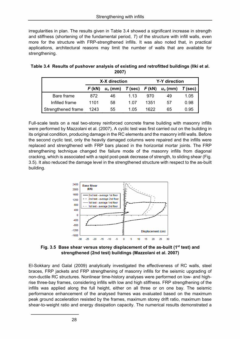
Strengthening with infills
28
irregularities in plan. The results given in Table 3.4 showed a significant increase in strength and stiffness (shortening of the fundamental period, T) of the structure with infill walls, even more for the structure with FRP-strengthened infills. It was also noted that, in practical applications, architectural reasons may limit the number of walls that are available for strengthening.
Table 3.4 Results of pushover analysis of existing and retrofitted buildings (Ilki et al. 2007)
X-X direction Y-Y direction
F (kN) uu (mm) T (sec) F (kN) uu (mm) T (sec)
Bare frame 872 46 1.13 970 49 1.05
Infilled frame 1101 58 1.07 1351 57 0.98
Strengthened frame 1243 55 1.05 1622 65 0.95
Full-scale tests on a real two-storey reinforced concrete frame building with masonry infills were performed by Mazzolani et al. (2007). A cyclic test was first carried out on the building in its original condition, producing damage in the RC elements and the masonry infill walls. Before the second cyclic test, only the heavily damaged columns were repaired and the infills were replaced and strengthened with FRP bars placed in the horizontal mortar joints. The FRP strengthening technique changed the failure mode of the masonry infills from diagonal cracking, which is associated with a rapid post-peak decrease of strength, to sliding shear (Fig. 3.5). It also reduced the damage level in the strengthened structure with respect to the as-built building.
Fig. 3.5 Base shear versus storey displacement of the as-built (1st test) and strengthened (2nd test) buildings (Mazzolani et al. 2007)
El-Sokkary and Galal (2009) analytically investigated the effectiveness of RC walls, steel braces, FRP jackets and FRP strengthening of masonry infills for the seismic upgrading of non-ductile RC structures. Nonlinear time-history analyses were performed on low- and high-rise three-bay frames, considering infills with low and high stiffness. FRP strengthening of the infills was applied along the full height, either on all three or on one bay. The seismic performance enhancement of the analysed frames was evaluated based on the maximum peak ground acceleration resisted by the frames, maximum storey drift ratio, maximum base shear-to-weight ratio and energy dissipation capacity. The numerical results demonstrated a
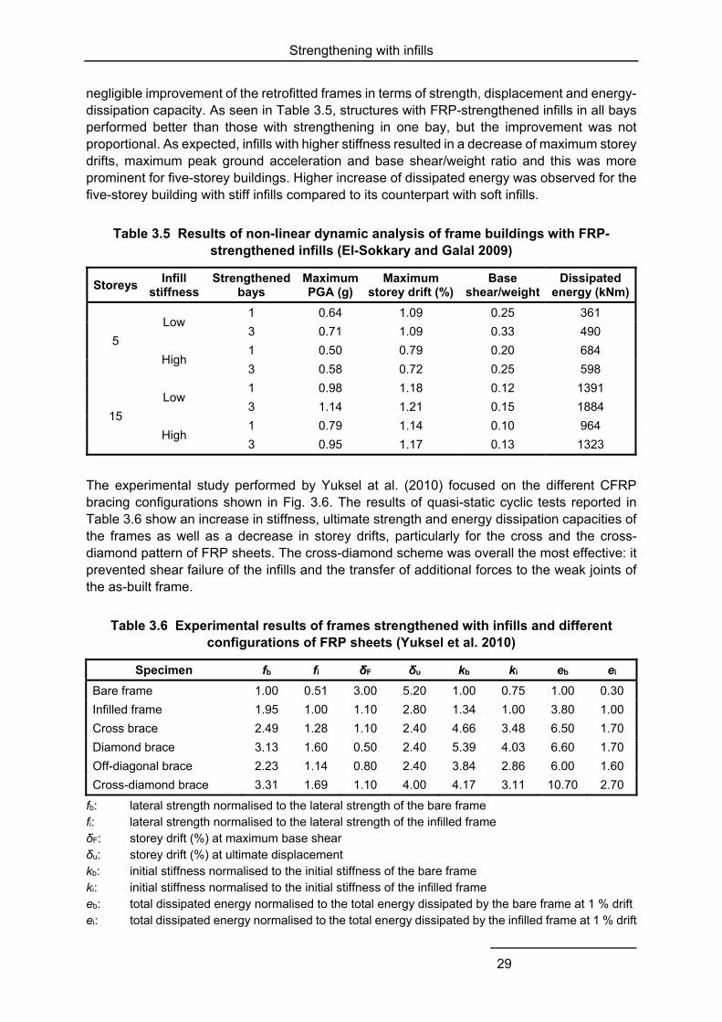
Strengthening with infills
29
negligible improvement of the retrofitted frames in terms of strength, displacement and energy-dissipation capacity. As seen in Table 3.5, structures with FRP-strengthened infills in all bays performed better than those with strengthening in one bay, but the improvement was not proportional. As expected, infills with higher stiffness resulted in a decrease of maximum storey drifts, maximum peak ground acceleration and base shear/weight ratio and this was more prominent for five-storey buildings. Higher increase of dissipated energy was observed for the five-storey building with stiff infills compared to its counterpart with soft infills.
Table 3.5 Results of non-linear dynamic analysis of frame buildings with FRP-strengthened infills (El-Sokkary and Galal 2009)
Storeys Infill
stiffness Strengthened
bays Maximum PGA (g)
Maximum storey drift (%)
Base shear/weight
Dissipated energy (kNm)
5
Low 1 0.64 1.09 0.25 361
3 0.71 1.09 0.33 490
High 1 0.50 0.79 0.20 684
3 0.58 0.72 0.25 598
15
Low 1 0.98 1.18 0.12 1391
3 1.14 1.21 0.15 1884
High 1 0.79 1.14 0.10 964
3 0.95 1.17 0.13 1323
The experimental study performed by Yuksel at al. (2010) focused on the different CFRP bracing configurations shown in Fig. 3.6. The results of quasi-static cyclic tests reported in Table 3.6 show an increase in stiffness, ultimate strength and energy dissipation capacities of the frames as well as a decrease in storey drifts, particularly for the cross and the cross-diamond pattern of FRP sheets. The cross-diamond scheme was overall the most effective: it prevented shear failure of the infills and the transfer of additional forces to the weak joints of the as-built frame.
Table 3.6 Experimental results of frames strengthened with infills and different configurations of FRP sheets (Yuksel et al. 2010)
Specimen fb fi δF δu kb ki eb ei
Bare frame 1.00 0.51 3.00 5.20 1.00 0.75 1.00 0.30
Infilled frame 1.95 1.00 1.10 2.80 1.34 1.00 3.80 1.00
Cross brace 2.49 1.28 1.10 2.40 4.66 3.48 6.50 1.70
Diamond brace 3.13 1.60 0.50 2.40 5.39 4.03 6.60 1.70
Off-diagonal brace 2.23 1.14 0.80 2.40 3.84 2.86 6.00 1.60
Cross-diamond brace 3.31 1.69 1.10 4.00 4.17 3.11 10.70 2.70
fb: lateral strength normalised to the lateral strength of the bare frame fi: lateral strength normalised to the lateral strength of the infilled frame δF: storey drift (%) at maximum base shear δu: storey drift (%) at ultimate displacement kb: initial stiffness normalised to the initial stiffness of the bare frame ki: initial stiffness normalised to the initial stiffness of the infilled frame eb: total dissipated energy normalised to the total energy dissipated by the bare frame at 1 % drift ei: total dissipated energy normalised to the total energy dissipated by the infilled frame at 1 % drift
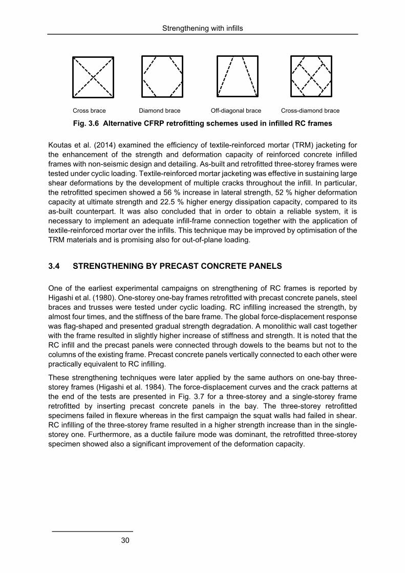
Strengthening with infills
30
Cross brace Diamond brace Off-diagonal brace Cross-diamond brace
Fig. 3.6 Alternative CFRP retrofitting schemes used in infilled RC frames
Koutas et al. (2014) examined the efficiency of textile-reinforced mortar (TRM) jacketing for the enhancement of the strength and deformation capacity of reinforced concrete infilled frames with non-seismic design and detailing. As-built and retrofitted three-storey frames were tested under cyclic loading. Textile-reinforced mortar jacketing was effective in sustaining large shear deformations by the development of multiple cracks throughout the infill. In particular, the retrofitted specimen showed a 56 % increase in lateral strength, 52 % higher deformation capacity at ultimate strength and 22.5 % higher energy dissipation capacity, compared to its as-built counterpart. It was also concluded that in order to obtain a reliable system, it is necessary to implement an adequate infill-frame connection together with the application of textile-reinforced mortar over the infills. This technique may be improved by optimisation of the TRM materials and is promising also for out-of-plane loading.
3.4 STRENGTHENING BY PRECAST CONCRETE PANELS
One of the earliest experimental campaigns on strengthening of RC frames is reported by Higashi et al. (1980). One-storey one-bay frames retrofitted with precast concrete panels, steel braces and trusses were tested under cyclic loading. RC infilling increased the strength, by almost four times, and the stiffness of the bare frame. The global force-displacement response was flag-shaped and presented gradual strength degradation. A monolithic wall cast together with the frame resulted in slightly higher increase of stiffness and strength. It is noted that the RC infill and the precast panels were connected through dowels to the beams but not to the columns of the existing frame. Precast concrete panels vertically connected to each other were practically equivalent to RC infilling.
These strengthening techniques were later applied by the same authors on one-bay three-storey frames (Higashi et al. 1984). The force-displacement curves and the crack patterns at the end of the tests are presented in Fig. 3.7 for a three-storey and a single-storey frame retrofitted by inserting precast concrete panels in the bay. The three-storey retrofitted specimens failed in flexure whereas in the first campaign the squat walls had failed in shear. RC infilling of the three-storey frame resulted in a higher strength increase than in the single-storey one. Furthermore, as a ductile failure mode was dominant, the retrofitted three-storey specimen showed also a significant improvement of the deformation capacity.
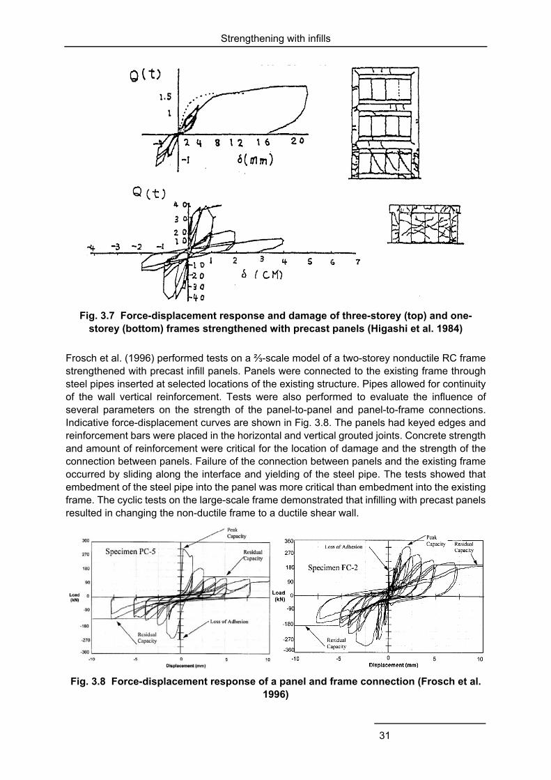
Strengthening with infills
31
Fig. 3.7 Force-displacement response and damage of three-storey (top) and one-storey (bottom) frames strengthened with precast panels (Higashi et al. 1984)
Frosch et al. (1996) performed tests on a ⅔-scale model of a two-storey nonductile RC frame strengthened with precast infill panels. Panels were connected to the existing frame through steel pipes inserted at selected locations of the existing structure. Pipes allowed for continuity of the wall vertical reinforcement. Tests were also performed to evaluate the influence of several parameters on the strength of the panel-to-panel and panel-to-frame connections. Indicative force-displacement curves are shown in Fig. 3.8. The panels had keyed edges and reinforcement bars were placed in the horizontal and vertical grouted joints. Concrete strength and amount of reinforcement were critical for the location of damage and the strength of the connection between panels. Failure of the connection between panels and the existing frame occurred by sliding along the interface and yielding of the steel pipe. The tests showed that embedment of the steel pipe into the panel was more critical than embedment into the existing frame. The cyclic tests on the large-scale frame demonstrated that infilling with precast panels resulted in changing the non-ductile frame to a ductile shear wall.
Fig. 3.8 Force-displacement response of a panel and frame connection (Frosch et al. 1996)
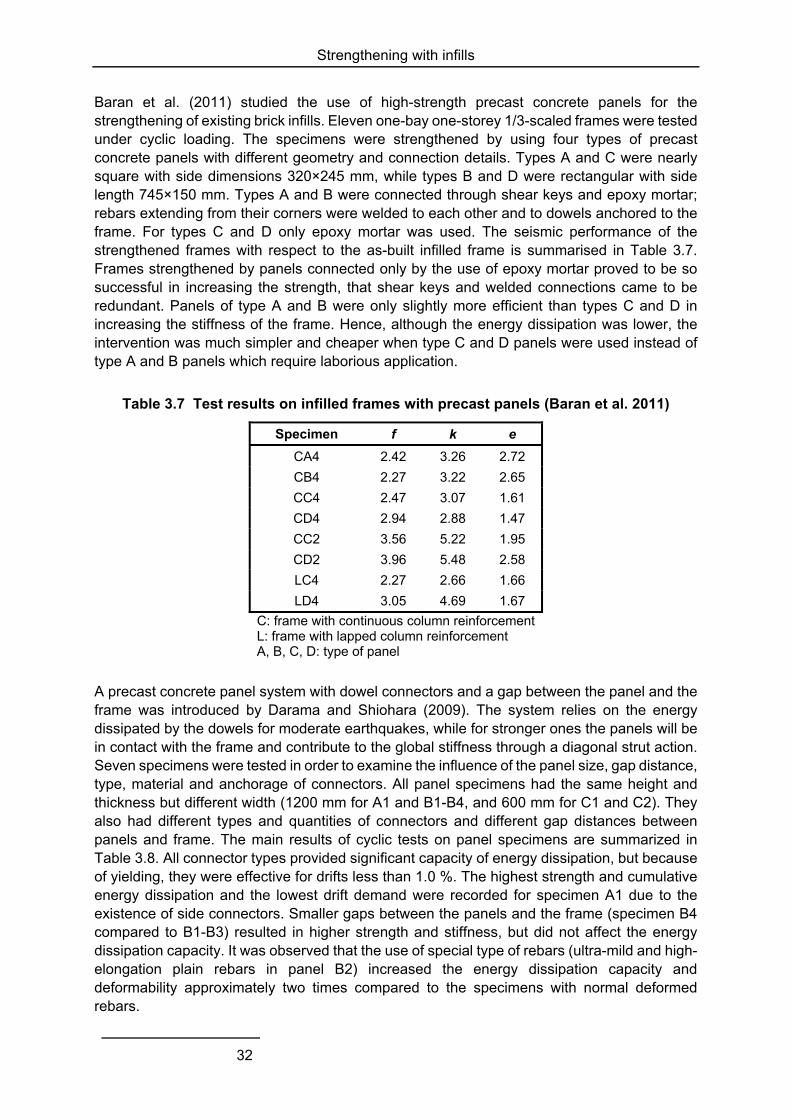
Strengthening with infills
32
Baran et al. (2011) studied the use of high-strength precast concrete panels for the strengthening of existing brick infills. Eleven one-bay one-storey 1/3-scaled frames were tested under cyclic loading. The specimens were strengthened by using four types of precast concrete panels with different geometry and connection details. Types A and C were nearly square with side dimensions 320×245 mm, while types B and D were rectangular with side length 745×150 mm. Types A and B were connected through shear keys and epoxy mortar; rebars extending from their corners were welded to each other and to dowels anchored to the frame. For types C and D only epoxy mortar was used. The seismic performance of the strengthened frames with respect to the as-built infilled frame is summarised in Table 3.7. Frames strengthened by panels connected only by the use of epoxy mortar proved to be so successful in increasing the strength, that shear keys and welded connections came to be redundant. Panels of type A and B were only slightly more efficient than types C and D in increasing the stiffness of the frame. Hence, although the energy dissipation was lower, the intervention was much simpler and cheaper when type C and D panels were used instead of type A and B panels which require laborious application.
Table 3.7 Test results on infilled frames with precast panels (Baran et al. 2011)
Specimen f k e
CA4 2.42 3.26 2.72
CB4 2.27 3.22 2.65
CC4 2.47 3.07 1.61
CD4 2.94 2.88 1.47
CC2 3.56 5.22 1.95
CD2 3.96 5.48 2.58
LC4 2.27 2.66 1.66
LD4 3.05 4.69 1.67
C: frame with continuous column reinforcement L: frame with lapped column reinforcement A, B, C, D: type of panel
A precast concrete panel system with dowel connectors and a gap between the panel and the frame was introduced by Darama and Shiohara (2009). The system relies on the energy dissipated by the dowels for moderate earthquakes, while for stronger ones the panels will be in contact with the frame and contribute to the global stiffness through a diagonal strut action. Seven specimens were tested in order to examine the influence of the panel size, gap distance, type, material and anchorage of connectors. All panel specimens had the same height and thickness but different width (1200 mm for A1 and B1-B4, and 600 mm for C1 and C2). They also had different types and quantities of connectors and different gap distances between panels and frame. The main results of cyclic tests on panel specimens are summarized in Table 3.8. All connector types provided significant capacity of energy dissipation, but because of yielding, they were effective for drifts less than 1.0 %. The highest strength and cumulative energy dissipation and the lowest drift demand were recorded for specimen A1 due to the existence of side connectors. Smaller gaps between the panels and the frame (specimen B4 compared to B1-B3) resulted in higher strength and stiffness, but did not affect the energy dissipation capacity. It was observed that the use of special type of rebars (ultra-mild and high-elongation plain rebars in panel B2) increased the energy dissipation capacity and deformability approximately two times compared to the specimens with normal deformed rebars.
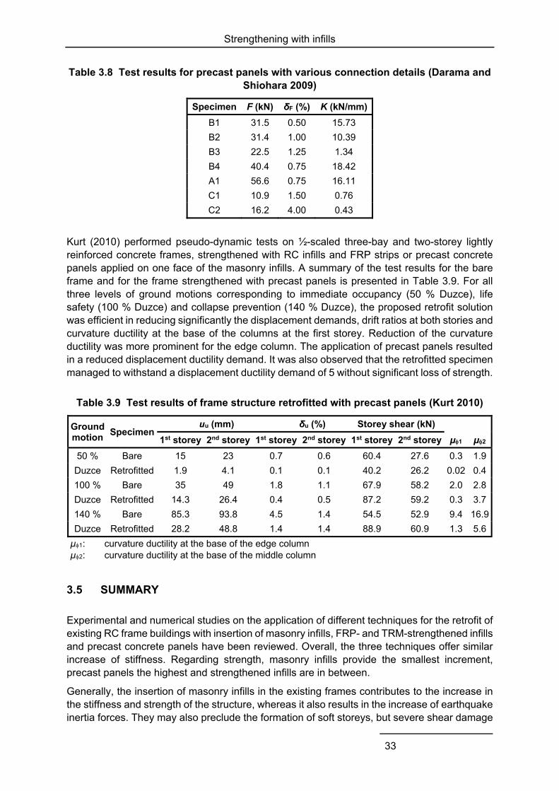
Strengthening with infills
33
Table 3.8 Test results for precast panels with various connection details (Darama and Shiohara 2009)
Specimen F (kN) δF (%) K (kN/mm)
B1 31.5 0.50 15.73
B2 31.4 1.00 10.39
B3 22.5 1.25 1.34
B4 40.4 0.75 18.42
A1 56.6 0.75 16.11
C1 10.9 1.50 0.76
C2 16.2 4.00 0.43
Kurt (2010) performed pseudo-dynamic tests on ½-scaled three-bay and two-storey lightly reinforced concrete frames, strengthened with RC infills and FRP strips or precast concrete panels applied on one face of the masonry infills. A summary of the test results for the bare frame and for the frame strengthened with precast panels is presented in Table 3.9. For all three levels of ground motions corresponding to immediate occupancy (50 % Duzce), life safety (100 % Duzce) and collapse prevention (140 % Duzce), the proposed retrofit solution was efficient in reducing significantly the displacement demands, drift ratios at both stories and curvature ductility at the base of the columns at the first storey. Reduction of the curvature ductility was more prominent for the edge column. The application of precast panels resulted in a reduced displacement ductility demand. It was also observed that the retrofitted specimen managed to withstand a displacement ductility demand of 5 without significant loss of strength.
Table 3.9 Test results of frame structure retrofitted with precast panels (Kurt 2010)
Ground motion
Specimen uu (mm) δu (%) Storey shear (kN)
µ1 µ21st storey 2nd storey 1st storey 2nd storey 1st storey 2nd storey
50 % Bare 15 23 0.7 0.6 60.4 27.6 0.3 1.9
Duzce Retrofitted 1.9 4.1 0.1 0.1 40.2 26.2 0.02 0.4
100 % Bare 35 49 1.8 1.1 67.9 58.2 2.0 2.8
Duzce Retrofitted 14.3 26.4 0.4 0.5 87.2 59.2 0.3 3.7
140 % Bare 85.3 93.8 4.5 1.4 54.5 52.9 9.4 16.9
Duzce Retrofitted 28.2 48.8 1.4 1.4 88.9 60.9 1.3 5.6
µ1: curvature ductility at the base of the edge column µ2: curvature ductility at the base of the middle column
3.5 SUMMARY
Experimental and numerical studies on the application of different techniques for the retrofit of existing RC frame buildings with insertion of masonry infills, FRP- and TRM-strengthened infills and precast concrete panels have been reviewed. Overall, the three techniques offer similar increase of stiffness. Regarding strength, masonry infills provide the smallest increment, precast panels the highest and strengthened infills are in between.
Generally, the insertion of masonry infills in the existing frames contributes to the increase in the stiffness and strength of the structure, whereas it also results in the increase of earthquake inertia forces. They may also preclude the formation of soft storeys, but severe shear damage
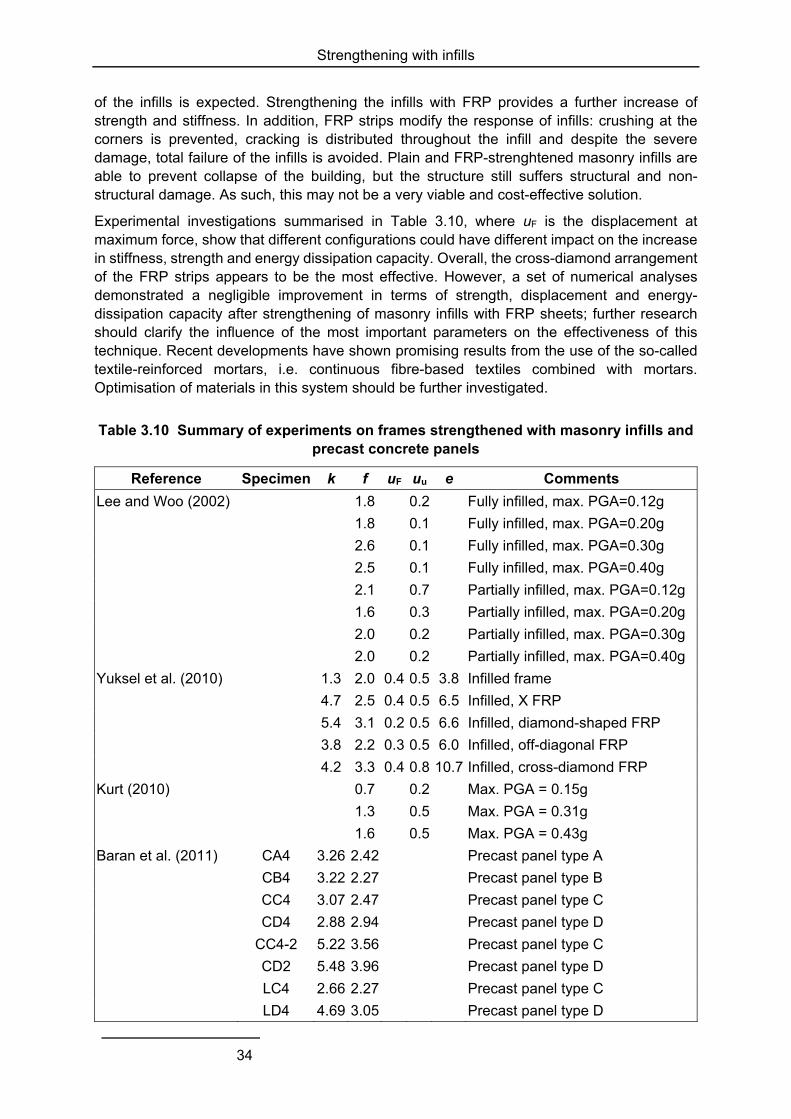
Strengthening with infills
34
of the infills is expected. Strengthening the infills with FRP provides a further increase of strength and stiffness. In addition, FRP strips modify the response of infills: crushing at the corners is prevented, cracking is distributed throughout the infill and despite the severe damage, total failure of the infills is avoided. Plain and FRP-strenghtened masonry infills are able to prevent collapse of the building, but the structure still suffers structural and non-structural damage. As such, this may not be a very viable and cost-effective solution.
Experimental investigations summarised in Table 3.10, where uF is the displacement at maximum force, show that different configurations could have different impact on the increase in stiffness, strength and energy dissipation capacity. Overall, the cross-diamond arrangement of the FRP strips appears to be the most effective. However, a set of numerical analyses demonstrated a negligible improvement in terms of strength, displacement and energy-dissipation capacity after strengthening of masonry infills with FRP sheets; further research should clarify the influence of the most important parameters on the effectiveness of this technique. Recent developments have shown promising results from the use of the so-called textile-reinforced mortars, i.e. continuous fibre-based textiles combined with mortars. Optimisation of materials in this system should be further investigated.
Table 3.10 Summary of experiments on frames strengthened with masonry infills and precast concrete panels
Reference Specimen k f uF uu e Comments
Lee and Woo (2002) 1.8 0.2 Fully infilled, max. PGA=0.12g
1.8 0.1 Fully infilled, max. PGA=0.20g
2.6 0.1 Fully infilled, max. PGA=0.30g
2.5 0.1 Fully infilled, max. PGA=0.40g
2.1 0.7 Partially infilled, max. PGA=0.12g
1.6 0.3 Partially infilled, max. PGA=0.20g
2.0 0.2 Partially infilled, max. PGA=0.30g
2.0 0.2 Partially infilled, max. PGA=0.40g
Yuksel et al. (2010) 1.3 2.0 0.4 0.5 3.8 Infilled frame
4.7 2.5 0.4 0.5 6.5 Infilled, X FRP
5.4 3.1 0.2 0.5 6.6 Infilled, diamond-shaped FRP
3.8 2.2 0.3 0.5 6.0 Infilled, off-diagonal FRP
4.2 3.3 0.4 0.8 10.7 Infilled, cross-diamond FRP
Kurt (2010) 0.7 0.2 Max. PGA = 0.15g
1.3 0.5 Max. PGA = 0.31g
1.6 0.5 Max. PGA = 0.43g
Baran et al. (2011) CA4 3.26 2.42 Precast panel type A
CB4 3.22 2.27 Precast panel type B
CC4 3.07 2.47 Precast panel type C
CD4 2.88 2.94 Precast panel type D
CC4-2 5.22 3.56 Precast panel type C
CD2 5.48 3.96 Precast panel type D
LC4 2.66 2.27 Precast panel type C
LD4 4.69 3.05 Precast panel type D

Strengthening with infills
35
Frames strengthened by precast panels showed improved seismic performance which is evident through the increase in lateral load-carrying capacity, stiffness and energy dissipation capacity (Table 3.10). Panel-frame connections through epoxy mortar proved to be as successful as shear keys and welded connections, although they lead to less ductile behaviour.

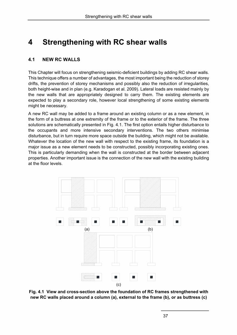
Strengthening with RC shear walls
37
4 Strengthening with RC shear walls
4.1 NEW RC WALLS
This Chapter will focus on strengthening seismic-deficient buildings by adding RC shear walls. This technique offers a number of advantages, the most important being the reduction of storey drifts, the prevention of storey mechanisms and possibly also the reduction of irregularities, both height-wise and in plan (e.g. Karadogan et al. 2009). Lateral loads are resisted mainly by the new walls that are appropriately designed to carry them. The existing elements are expected to play a secondary role, however local strengthening of some existing elements might be necessary.
A new RC wall may be added to a frame around an existing column or as a new element, in the form of a buttress at one extremity of the frame or to the exterior of the frame. The three solutions are schematically presented in Fig. 4.1. The first option entails higher disturbance to the occupants and more intensive secondary interventions. The two others minimise disturbance, but in turn require more space outside the building, which might not be available. Whatever the location of the new wall with respect to the existing frame, its foundation is a major issue as a new element needs to be constructed, possibly incorporating existing ones. This is particularly demanding when the wall is constructed at the border between adjacent properties. Another important issue is the connection of the new wall with the existing building at the floor levels.
(a) (b)
(c)
Fig. 4.1 View and cross-section above the foundation of RC frames strengthened with new RC walls placed around a column (a), external to the frame (b), or as buttress (c)
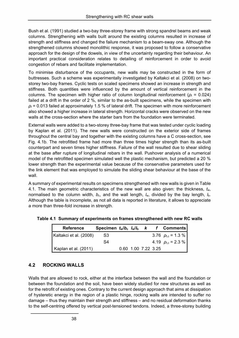
Strengthening with RC shear walls
38
Bush et al. (1991) studied a two-bay three-storey frame with strong spandrel beams and weak columns. Strengthening with walls built around the existing columns resulted in increase of strength and stiffness and changed the failure mechanism to a beam-sway one. Although the strengthened columns showed monolithic response, it was proposed to follow a conservative approach for the design of the dowels, in view of the uncertainty regarding their behaviour. An important practical consideration relates to detailing of reinforcement in order to avoid congestion of rebars and facilitate implementation.
To minimise disturbance of the occupants, new walls may be constructed in the form of buttresses. Such a scheme was experimentally investigated by Kaltakci et al. (2008) on two-storey two-bay frames. Cyclic tests on scaled specimens showed an increase in strength and stiffness. Both quantities were influenced by the amount of vertical reinforcement in the columns. The specimen with higher ratio of column longitudinal reinforcement (ρl = 0.024) failed at a drift in the order of 2 %, similar to the as-built specimens, while the specimen with ρl = 0.013 failed at approximately 1.5 % of lateral drift. The specimen with more reinforcement also showed a higher increase in lateral strength. Horizontal cracks were observed on the new walls at the cross-section where the starter bars from the foundation were terminated.
External walls were added to a two-storey three-bay frame that was tested under cyclic loading by Kaplan et al. (2011). The new walls were constructed on the exterior side of frames throughout the central bay and together with the existing columns have a C cross-section, see Fig. 4.1b. The retrofitted frame had more than three times higher strength than its as-built counterpart and seven times higher stiffness. Failure of the wall resulted due to shear sliding at the base after rupture of longitudinal rebars in the wall. Pushover analysis of a numerical model of the retrofitted specimen simulated well the plastic mechanism, but predicted a 20 % lower strength than the experimental value because of the conservative parameters used for the link element that was employed to simulate the sliding shear behaviour at the base of the wall.
A summary of experimental results on specimens strengthened with new walls is given in Table 4.1. The main geometric characteristics of the new wall are also given: the thickness, tw, normalised to the column width, bc, and the wall length, lw, divided by the bay length, lb. Although the table is incomplete, as not all data is reported in literature, it allows to appreciate a more than three-fold increase in strength.
Table 4.1 Summary of experiments on frames strengthened with new RC walls
Reference Specimen tw/bc lw/lb k f Comments
Kaltakci et al. (2008) S3 3.76 ρl,c = 1.3 %
S4 4.19 ρl,c = 2.3 %
Kaplan et al. (2011) 0.60 1.00 7.22 3.25
4.2 ROCKING WALLS
Walls that are allowed to rock, either at the interface between the wall and the foundation or between the foundation and the soil, have been widely studied for new structures as well as for the retrofit of existing ones. Contrary to the current design approach that aims at dissipation of hysteretic energy in the region of a plastic hinge, rocking walls are intended to suffer no damage – thus they maintain their strength and stiffness – and no residual deformation thanks to the self-centring offered by vertical post-tensioned tendons. Indeed, a three-storey building
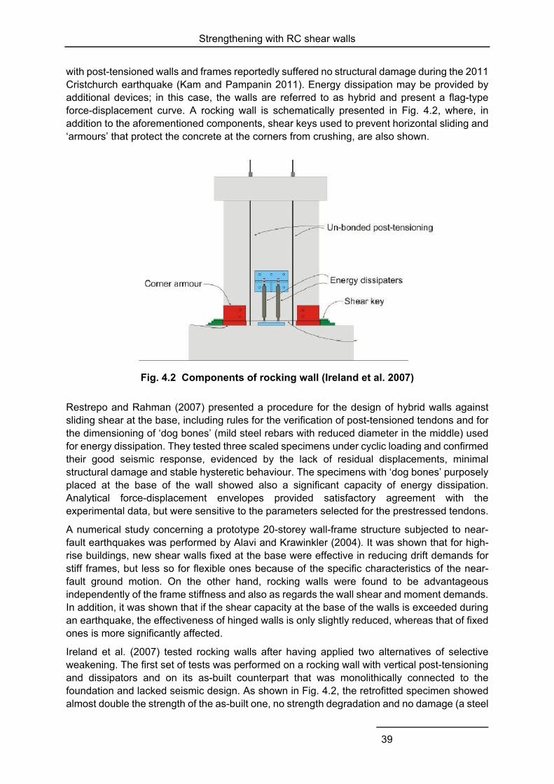
Strengthening with RC shear walls
39
with post-tensioned walls and frames reportedly suffered no structural damage during the 2011 Cristchurch earthquake (Kam and Pampanin 2011). Energy dissipation may be provided by additional devices; in this case, the walls are referred to as hybrid and present a flag-type force-displacement curve. A rocking wall is schematically presented in Fig. 4.2, where, in addition to the aforementioned components, shear keys used to prevent horizontal sliding and ‘armours’ that protect the concrete at the corners from crushing, are also shown.
Fig. 4.2 Components of rocking wall (Ireland et al. 2007)
Restrepo and Rahman (2007) presented a procedure for the design of hybrid walls against sliding shear at the base, including rules for the verification of post-tensioned tendons and for the dimensioning of ‘dog bones’ (mild steel rebars with reduced diameter in the middle) used for energy dissipation. They tested three scaled specimens under cyclic loading and confirmed their good seismic response, evidenced by the lack of residual displacements, minimal structural damage and stable hysteretic behaviour. The specimens with ‘dog bones’ purposely placed at the base of the wall showed also a significant capacity of energy dissipation. Analytical force-displacement envelopes provided satisfactory agreement with the experimental data, but were sensitive to the parameters selected for the prestressed tendons.
A numerical study concerning a prototype 20-storey wall-frame structure subjected to near-fault earthquakes was performed by Alavi and Krawinkler (2004). It was shown that for high-rise buildings, new shear walls fixed at the base were effective in reducing drift demands for stiff frames, but less so for flexible ones because of the specific characteristics of the near-fault ground motion. On the other hand, rocking walls were found to be advantageous independently of the frame stiffness and also as regards the wall shear and moment demands. In addition, it was shown that if the shear capacity at the base of the walls is exceeded during an earthquake, the effectiveness of hinged walls is only slightly reduced, whereas that of fixed ones is more significantly affected.
Ireland et al. (2007) tested rocking walls after having applied two alternatives of selective weakening. The first set of tests was performed on a rocking wall with vertical post-tensioning and dissipators and on its as-built counterpart that was monolithically connected to the foundation and lacked seismic design. As shown in Fig. 4.2, the retrofitted specimen showed almost double the strength of the as-built one, no strength degradation and no damage (a steel
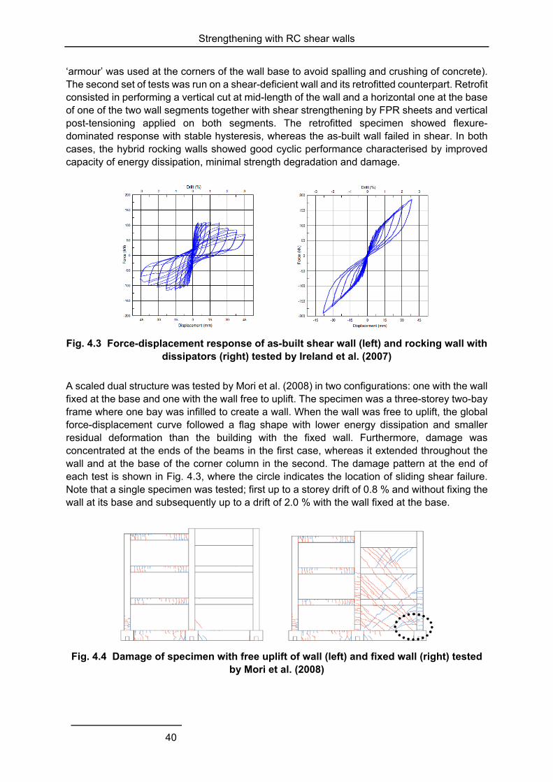
Strengthening with RC shear walls
40
‘armour’ was used at the corners of the wall base to avoid spalling and crushing of concrete). The second set of tests was run on a shear-deficient wall and its retrofitted counterpart. Retrofit consisted in performing a vertical cut at mid-length of the wall and a horizontal one at the base of one of the two wall segments together with shear strengthening by FPR sheets and vertical post-tensioning applied on both segments. The retrofitted specimen showed flexure-dominated response with stable hysteresis, whereas the as-built wall failed in shear. In both cases, the hybrid rocking walls showed good cyclic performance characterised by improved capacity of energy dissipation, minimal strength degradation and damage.
Fig. 4.3 Force-displacement response of as-built shear wall (left) and rocking wall with dissipators (right) tested by Ireland et al. (2007)
A scaled dual structure was tested by Mori et al. (2008) in two configurations: one with the wall fixed at the base and one with the wall free to uplift. The specimen was a three-storey two-bay frame where one bay was infilled to create a wall. When the wall was free to uplift, the global force-displacement curve followed a flag shape with lower energy dissipation and smaller residual deformation than the building with the fixed wall. Furthermore, damage was concentrated at the ends of the beams in the first case, whereas it extended throughout the wall and at the base of the corner column in the second. The damage pattern at the end of each test is shown in Fig. 4.3, where the circle indicates the location of sliding shear failure. Note that a single specimen was tested; first up to a storey drift of 0.8 % and without fixing the wall at its base and subsequently up to a drift of 2.0 % with the wall fixed at the base.
Fig. 4.4 Damage of specimen with free uplift of wall (left) and fixed wall (right) tested by Mori et al. (2008)
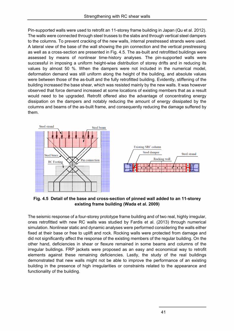
Strengthening with RC shear walls
41
Pin-supported walls were used to retrofit an 11-storey frame building in Japan (Qu et al. 2012). The walls were connected through steel trusses to the slabs and through vertical steel dampers to the columns. To prevent cracking of the new walls, internal prestressed strands were used. A lateral view of the base of the wall showing the pin connection and the vertical prestressing as well as a cross-section are presented in Fig. 4.5. The as-built and retrofitted buildings were assessed by means of nonlinear time-history analyses. The pin-supported walls were successful in imposing a uniform height-wise distribution of storey drifts and in reducing its values by almost 50 %. When the dampers were not included in the numerical model, deformation demand was still uniform along the height of the building, and absolute values were between those of the as-built and the fully retrofitted building. Evidently, stiffening of the building increased the base shear, which was resisted mainly by the new walls. It was however observed that force demand increased at some locations of existing members that as a result would need to be upgraded. Retrofit offered also the advantage of concentrating energy dissipation on the dampers and notably reducing the amount of energy dissipated by the columns and beams of the as-built frame, and consequently reducing the damage suffered by them.
Fig. 4.5 Detail of the base and cross-section of pinned wall added to an 11-storey existing frame building (Wada et al. 2009)
The seismic response of a four-storey prototype frame building and of two real, highly irregular, ones retrofitted with new RC walls was studied by Fardis et al. (2013) through numerical simulation. Nonlinear static and dynamic analyses were performed considering the walls either fixed at their base or free to uplift and rock. Rocking walls were protected from damage and did not significantly affect the response of the existing members of the regular building. On the other hand, deficiencies in shear or flexure remained in some beams and columns of the irregular buildings. FRP jackets were proposed as an easy and economical way to retrofit elements against these remaining deficiencies. Lastly, the study of the real buildings demonstrated that new walls might not be able to improve the performance of an existing building in the presence of high irregularities or constraints related to the appearance and functionality of the building.
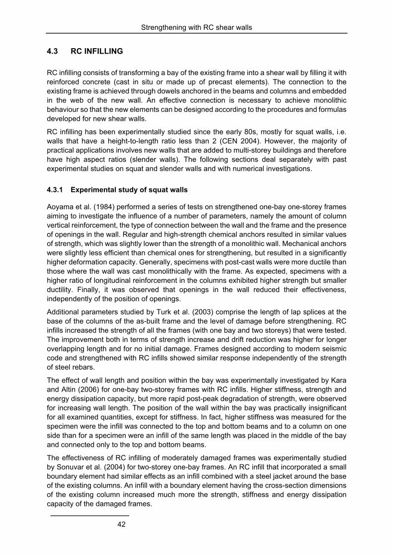
Strengthening with RC shear walls
42
4.3 RC INFILLING
RC infilling consists of transforming a bay of the existing frame into a shear wall by filling it with reinforced concrete (cast in situ or made up of precast elements). The connection to the existing frame is achieved through dowels anchored in the beams and columns and embedded in the web of the new wall. An effective connection is necessary to achieve monolithic behaviour so that the new elements can be designed according to the procedures and formulas developed for new shear walls.
RC infilling has been experimentally studied since the early 80s, mostly for squat walls, i.e. walls that have a height-to-length ratio less than 2 (CEN 2004). However, the majority of practical applications involves new walls that are added to multi-storey buildings and therefore have high aspect ratios (slender walls). The following sections deal separately with past experimental studies on squat and slender walls and with numerical investigations.
4.3.1 Experimental study of squat walls
Aoyama et al. (1984) performed a series of tests on strengthened one-bay one-storey frames aiming to investigate the influence of a number of parameters, namely the amount of column vertical reinforcement, the type of connection between the wall and the frame and the presence of openings in the wall. Regular and high-strength chemical anchors resulted in similar values of strength, which was slightly lower than the strength of a monolithic wall. Mechanical anchors were slightly less efficient than chemical ones for strengthening, but resulted in a significantly higher deformation capacity. Generally, specimens with post-cast walls were more ductile than those where the wall was cast monolithically with the frame. As expected, specimens with a higher ratio of longitudinal reinforcement in the columns exhibited higher strength but smaller ductility. Finally, it was observed that openings in the wall reduced their effectiveness, independently of the position of openings.
Additional parameters studied by Turk et al. (2003) comprise the length of lap splices at the base of the columns of the as-built frame and the level of damage before strengthening. RC infills increased the strength of all the frames (with one bay and two storeys) that were tested. The improvement both in terms of strength increase and drift reduction was higher for longer overlapping length and for no initial damage. Frames designed according to modern seismic code and strengthened with RC infills showed similar response independently of the strength of steel rebars.
The effect of wall length and position within the bay was experimentally investigated by Kara and Altin (2006) for one-bay two-storey frames with RC infills. Higher stiffness, strength and energy dissipation capacity, but more rapid post-peak degradation of strength, were observed for increasing wall length. The position of the wall within the bay was practically insignificant for all examined quantities, except for stiffness. In fact, higher stiffness was measured for the specimen were the infill was connected to the top and bottom beams and to a column on one side than for a specimen were an infill of the same length was placed in the middle of the bay and connected only to the top and bottom beams.
The effectiveness of RC infilling of moderately damaged frames was experimentally studied by Sonuvar et al. (2004) for two-storey one-bay frames. An RC infill that incorporated a small boundary element had similar effects as an infill combined with a steel jacket around the base of the existing columns. An infill with a boundary element having the cross-section dimensions of the existing column increased much more the strength, stiffness and energy dissipation capacity of the damaged frames.
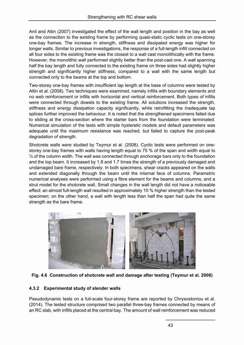
Strengthening with RC shear walls
43
Anil and Altin (2007) investigated the effect of the wall length and position in the bay as well as the connection to the existing frame by performing quasi-static cyclic tests on one-storey one-bay frames. The increase in strength, stiffness and dissipated energy was higher for longer walls. Similar to previous investigations, the response of a full-length infill connected on all four sides to the existing frame was the closest to a wall cast monolithically with the frame. However, the monolithic wall performed slightly better than the post-cast one. A wall spanning half the bay length and fully connected to the existing frame on three sides had slightly higher strength and significantly higher stiffness, compared to a wall with the same length but connected only to the beams at the top and bottom.
Two-storey one-bay frames with insufficient lap length at the base of columns were tested by Altin et al. (2008). Two techniques were examined, namely infills with boundary elements and no web reinforcement or infills with horizontal and vertical reinforcement. Both types of infills were connected through dowels to the existing frame. All solutions increased the strength, stiffness and energy dissipation capacity significantly, while retrofitting the inadequate lap splices further improved the behaviour. It is noted that the strengthened specimens failed due to sliding at the cross-section where the starter bars from the foundation were terminated. Numerical simulation of the tests with simple hysteretic models and default parameters was adequate until the maximum resistance was reached, but failed to capture the post-peak degradation of strength.
Shotcrete walls were studied by Teymur et al. (2008). Cyclic tests were performed on one-storey one-bay frames with walls having length equal to 75 % of the span and width equal to ¼ of the column width. The wall was connected through anchorage bars only to the foundation and the top beam. It increased by 1.8 and 1.7 times the strength of a previously damaged and undamaged bare frame, respectively. In both specimens, shear cracks appeared on the walls and extended diagonally through the beam until the internal face of columns. Parametric numerical analyses were performed using a fibre element for the beams and columns, and a strut model for the shotcrete wall. Small changes in the wall length did not have a noticeable effect: an almost full-length wall resulted in approximately 10 % higher strength than the tested specimen; on the other hand, a wall with length less than half the span had quite the same strength as the bare frame.
Fig. 4.6 Construction of shotcrete wall and damage after testing (Teymur et al. 2008)
4.3.2 Experimental study of slender walls
Pseudodynamic tests on a full-scale four-storey frame are reported by Chrysostomou et al. (2014). The tested structure comprised two parallel three-bay frames connected by means of an RC slab, with infills placed at the central bay. The amount of wall reinforcement was reduced
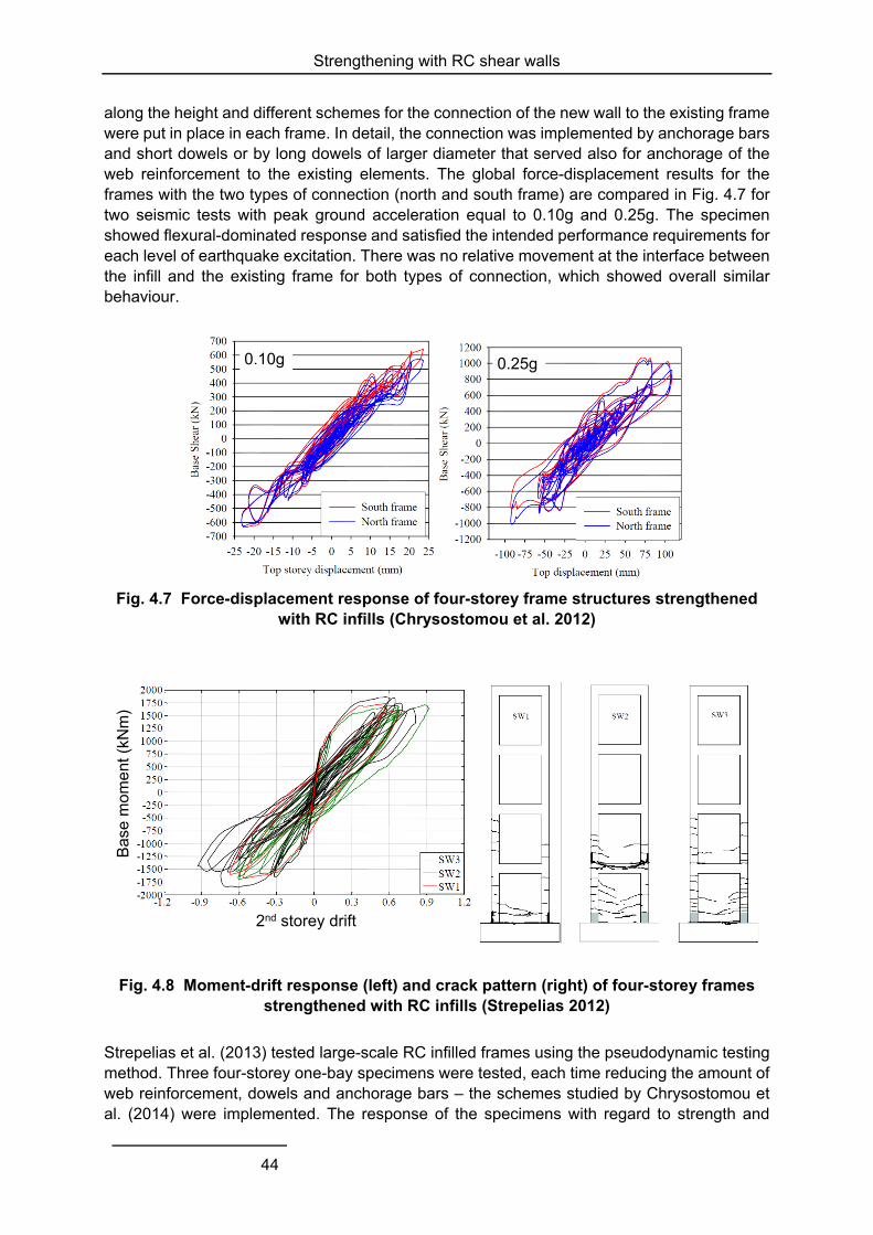
Strengthening with RC shear walls
44
along the height and different schemes for the connection of the new wall to the existing frame were put in place in each frame. In detail, the connection was implemented by anchorage bars and short dowels or by long dowels of larger diameter that served also for anchorage of the web reinforcement to the existing elements. The global force-displacement results for the frames with the two types of connection (north and south frame) are compared in Fig. 4.7 for two seismic tests with peak ground acceleration equal to 0.10g and 0.25g. The specimen showed flexural-dominated response and satisfied the intended performance requirements for each level of earthquake excitation. There was no relative movement at the interface between the infill and the existing frame for both types of connection, which showed overall similar behaviour.
Fig. 4.7 Force-displacement response of four-storey frame structures strengthened with RC infills (Chrysostomou et al. 2012)
Bas
e m
ome
nt (
kNm
)
2nd storey drift
Fig. 4.8 Moment-drift response (left) and crack pattern (right) of four-storey frames strengthened with RC infills (Strepelias 2012)
Strepelias et al. (2013) tested large-scale RC infilled frames using the pseudodynamic testing method. Three four-storey one-bay specimens were tested, each time reducing the amount of web reinforcement, dowels and anchorage bars – the schemes studied by Chrysostomou et al. (2014) were implemented. The response of the specimens with regard to strength and
0.10g 0.25g
Strengthening with RC shear walls
45
distribution of damage was practically independent of the connection scheme, as seen in Fig. 4.8. There were larger relative displacement at the interface with less reinforcement, but still below the design strength of dowels. Only hairline cracks were observed at the interface at the upper storeys of two specimens where a nominal amount of dowels was placed. All specimens failed in a flexure-dominated mode, but the location of the critical cross-section was influenced by the presence of lapped splices and the amount of web reinforcement. The crack pattern for the three specimens SW1, SW2 and SW3, with decreasing amount of web reinforcement, is shown in Fig. 4.8(right). The critical cross-section of SW1 was at the termination of the starter bars at the base of the columns and for this reason, SW2 and SW3 were strengthened with U-shaped FRP jackets. Specimen SW2 failed at the cross-section right above the spliced rebars at the base of the second storey, while SW3 failed at the base because of the reduced moment resistance due to the smaller amount of web reinforcement. The experimental values of stiffness and deformation were very close to those calculated according to Eurocode 8 (CEN 2005) and the fib Model Code (fib 2013), therefore the RC infills and existing frame may be considered as monolithic walls. Strepelias (2012) performed numerical simulations of the tests and obtained better agreement between experimental and numerical response when using a fibre model or a beam model with a trilinear skeleton curve instead of a bilinear one.
4.3.3 Summary of experimental studies
The results of the experimental investigations presented above are summarised in Table 4.2. Further to the symbols used before, hw/lw is the wall aspect ratio, ρs,d is the dowel reinforcement ratio, i.e. the area of dowels along the perimeter of the new element divided by the area of the interface between the new wall and the existing frame.
The experimental results show a very large scatter of all the measures used to quantify the effectiveness of retrofit. Overall, it is confirmed that walls with larger dimensions (thickness and/or length) offer higher increase in strength and stiffness and larger reduction of drifts, both at peak strength and at failure.
RC infills that span the whole bay and are connected on all four sides to the existing beams and columns behave almost as well as walls cast monolithic to the frame. Infills that are connected only to the beams or are made of precast panels without connection through their vertical interface evidently provide smaller enhancement of strength and stiffness. As a matter of fact, the normalised strength, f, and the dowel reinforcement ratio, ρs,d, have the highest correlation among all couples of response and geometry parameters. It is recalled that most of the tested specimens were squat and therefore failed in shear, for which continuity and proper anchorage of horizontal reinforcement is critical.
Finally, it is shown that the presence of spliced bars with insufficient lap length reduces the effectiveness of this strengthening technique. In most of these specimens, failure occurred at the cross-section above the starter bars at the base. However, steel or FRP jackets around the base of columns with short lap length were able to prevent this failure mode.
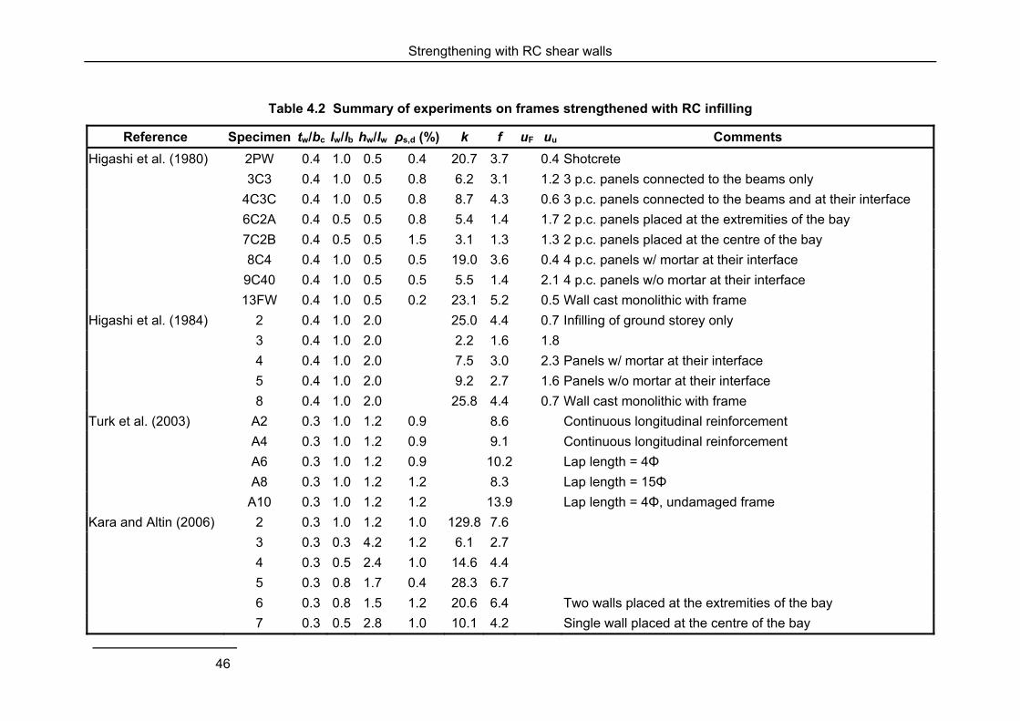
Strengthening with RC shear walls
46
Table 4.2 Summary of experiments on frames strengthened with RC infilling
Reference Specimen tw/bc lw/lb hw/lw ρs,d (%) k f uF uu Comments
Higashi et al. (1980) 2PW 0.4 1.0 0.5 0.4 20.7 3.7 0.4 Shotcrete
3C3 0.4 1.0 0.5 0.8 6.2 3.1 1.2 3 p.c. panels connected to the beams only
4C3C 0.4 1.0 0.5 0.8 8.7 4.3 0.6 3 p.c. panels connected to the beams and at their interface
6C2A 0.4 0.5 0.5 0.8 5.4 1.4 1.7 2 p.c. panels placed at the extremities of the bay
7C2B 0.4 0.5 0.5 1.5 3.1 1.3 1.3 2 p.c. panels placed at the centre of the bay
8C4 0.4 1.0 0.5 0.5 19.0 3.6 0.4 4 p.c. panels w/ mortar at their interface
9C40 0.4 1.0 0.5 0.5 5.5 1.4 2.1 4 p.c. panels w/o mortar at their interface
13FW 0.4 1.0 0.5 0.2 23.1 5.2 0.5 Wall cast monolithic with frame
Higashi et al. (1984) 2 0.4 1.0 2.0 25.0 4.4 0.7 Infilling of ground storey only
3 0.4 1.0 2.0 2.2 1.6 1.8
4 0.4 1.0 2.0 7.5 3.0 2.3 Panels w/ mortar at their interface
5 0.4 1.0 2.0 9.2 2.7 1.6 Panels w/o mortar at their interface
8 0.4 1.0 2.0 25.8 4.4 0.7 Wall cast monolithic with frame
Turk et al. (2003) A2 0.3 1.0 1.2 0.9 8.6 Continuous longitudinal reinforcement
A4 0.3 1.0 1.2 0.9 9.1 Continuous longitudinal reinforcement
A6 0.3 1.0 1.2 0.9 10.2 Lap length = 4Φ
A8 0.3 1.0 1.2 1.2 8.3 Lap length = 15Φ
A10 0.3 1.0 1.2 1.2 13.9 Lap length = 4Φ, undamaged frame
Kara and Altin (2006) 2 0.3 1.0 1.2 1.0 129.8 7.6
3 0.3 0.3 4.2 1.2 6.1 2.7
4 0.3 0.5 2.4 1.0 14.6 4.4
5 0.3 0.8 1.7 0.4 28.3 6.7
6 0.3 0.8 1.5 1.2 20.6 6.4 Two walls placed at the extremities of the bay
7 0.3 0.5 2.8 1.0 10.1 4.2 Single wall placed at the centre of the bay
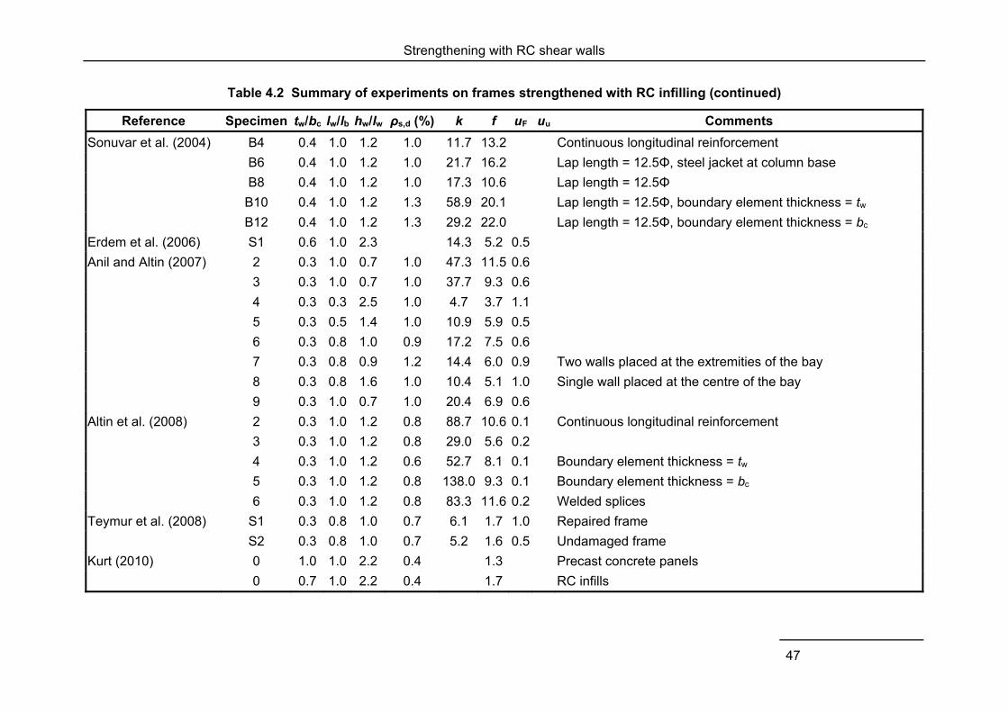
Strengthening with RC shear walls
47
Table 4.2 Summary of experiments on frames strengthened with RC infilling (continued)
Reference Specimen tw/bc lw/lb hw/lw ρs,d (%) k f uF uu Comments
Sonuvar et al. (2004) B4 0.4 1.0 1.2 1.0 11.7 13.2 Continuous longitudinal reinforcement
B6 0.4 1.0 1.2 1.0 21.7 16.2 Lap length = 12.5Φ, steel jacket at column base
B8 0.4 1.0 1.2 1.0 17.3 10.6 Lap length = 12.5Φ
B10 0.4 1.0 1.2 1.3 58.9 20.1 Lap length = 12.5Φ, boundary element thickness = tw
B12 0.4 1.0 1.2 1.3 29.2 22.0 Lap length = 12.5Φ, boundary element thickness = bc
Erdem et al. (2006) S1 0.6 1.0 2.3 14.3 5.2 0.5
Anil and Altin (2007) 2 0.3 1.0 0.7 1.0 47.3 11.5 0.6
3 0.3 1.0 0.7 1.0 37.7 9.3 0.6
4 0.3 0.3 2.5 1.0 4.7 3.7 1.1
5 0.3 0.5 1.4 1.0 10.9 5.9 0.5
6 0.3 0.8 1.0 0.9 17.2 7.5 0.6
7 0.3 0.8 0.9 1.2 14.4 6.0 0.9 Two walls placed at the extremities of the bay
8 0.3 0.8 1.6 1.0 10.4 5.1 1.0 Single wall placed at the centre of the bay
9 0.3 1.0 0.7 1.0 20.4 6.9 0.6
Altin et al. (2008) 2 0.3 1.0 1.2 0.8 88.7 10.6 0.1 Continuous longitudinal reinforcement
3 0.3 1.0 1.2 0.8 29.0 5.6 0.2
4 0.3 1.0 1.2 0.6 52.7 8.1 0.1 Boundary element thickness = tw
5 0.3 1.0 1.2 0.8 138.0 9.3 0.1 Boundary element thickness = bc
6 0.3 1.0 1.2 0.8 83.3 11.6 0.2 Welded splices
Teymur et al. (2008) S1 0.3 0.8 1.0 0.7 6.1 1.7 1.0 Repaired frame
S2 0.3 0.8 1.0 0.7 5.2 1.6 0.5 Undamaged frame
Kurt (2010) 0 1.0 1.0 2.2 0.4 1.3 Precast concrete panels
0 0.7 1.0 2.2 0.4 1.7 RC infills
Strengthening with RC shear walls
48
4.3.4 Numerical studies
Pincheira and Jirsa (1995) performed static and dynamic numerical analysis of low-, mid- and high-rise RC frames retrofitted with post-tensioned braces, steel braces and RC infills. All retrofit strategies increased the strength and stiffness of the frame buildings, but their effectiveness varied with the structural properties of the buildings and the retrofit pattern. New RC walls performed satisfactorily in all the examined cases. However, it was noted that all schemes modified the response mechanism of the building and in certain cases increased the demand on existing elements.
Phan and Lew (1996) performed numerical analyses to investigate the effect of wall thickness, reinforcement ratio and area of anchors on the shear strength and drift demand of frames strengthened with RC infills. Based on experimental data from 55 specimens, a relationship was established between the parameters of the hysteretic model and the materials, geometry and reinforcement of specimens. These relationships were used to numerically simulate one-storey one-bay frames for a range of variable parameters. Higher wall thickness was verified to increase the strength and decrease the deformation demand; the obtained curves may be used to design the intervention for the desired balance between strength and stiffness. The amount of wall reinforcement did not appear to have influence neither on the strength nor on the drift of the strengthened walls. Finally, increase of the area of anchors resulted in slightly higher strength and a rapid reduction of drift demand. However, drift demand appears practically unaffected for dowel reinforcement ratios ρs,d > 0.9.
Yang et al. (2012) numerically investigated the effect of new walls, braces and dampers added to a regular five-storey frame structure. Shear walls were more effective than other solutions in reducing the maximum drift demand. Longer walls produced a higher decrease of deformation demand for the earthquake corresponding to the operational limit state. However, wall length did not have a marked effect at the immediate occupancy and life-safety limit states.
4.4 SUMMARY
Experimental and numerical studies on the use of new shear walls for the strengthening of existing RC frame buildings have been reviewed. Walls may be constructed as new elements around an existing column, placed to the exterior of the frame, or by infilling (totally or partially) a bay of the existing frame. Walls may be designed and constructed to rock at their base above the foundation, or to allow uplifting of the foundation from the soil. Rocking/uplifting walls are expected to suffer minimum damage and can be combined with energy dissipating devices.
New shear walls improve the global response of the building in terms of stiffness, strength and displacement demand. Depending on the layout of the existing building, they may also reduce irregularity. Retrofit by new walls causes little disturbance to occupants and minimises structural interventions on other existing elements: as the structure becomes stiffer, it attracts higher forces, which are mainly resisted by the new walls. However, these benefits are realised if the walls are adequately connected to the existing beams, columns and slabs and have appropriate foundations; these requirements are difficult to put into practice.
Previous research works that are available in literature have examined the influence of a number of parameters on the response of the strengthened frame. These parameters include the geometry (height, length and width) of the new shear wall, the amount of longitudinal and transverse reinforcement of the existing and new elements, the amount of dowels at the
Strengthening with RC shear walls
49
interface between new and existing elements, the dimensions and reinforcement of wall boundary elements, and the location and area of openings in the wall. Overall, it is shown that walls with large dimensions result in a higher increase in strength and stiffness and larger reduction of drifts. Previous damage on the frame or deficiencies, such as short overlap length, reduce the effectiveness of strengthening.
RC infills that are connected on all four sides to the existing beams and columns behave almost as well as walls cast monolithic with the frame. Infills that are connected only to the beams or are made of precast panels without connection through their vertical interface evidently provide smaller enhancement of strength and stiffness. Dowels and anchorage bars designed according to current rules will probably result in reinforcement congestion, while there is experimental evidence that design rules may be relaxed without affecting the response.
Provided that the connection to the existing elements is (almost) monolithic, existing design expressions for strength and stiffness can be used. As for other elements, more elaborated numerical models are more accurate, particularly until attainment of the maximum resistance, but are not always successful in simulating the post-peak response.
Lastly, it is noted that the majority of past experimental tests has been performed on single-storey walls, while practical applications involve mostly mid- or high-rise buildings. Relevant research has demonstrated the different failure modes of squat and slender walls: the behaviour of walls with high aspect ratio is mainly flexural and therefore associated to stable hysteretic response and improved capacity of energy dissipation.

Conclusions
51
5 Conclusions
Extensive experimental testing and numerical analyses of elements and structures have demonstrated the feasibility and effectiveness of steel bracing, infilling and addition of shear walls for the enhancement of the seismic behaviour of existing RC frame buildings. All three retrofit methods increase global strength and stiffness. In certain cases, they provide additional energy dissipation and help reducing irregularities. However, architectural and functional constraints in real buildings may impose limits on the location and geometry of braces, infills and shear walls and therefore on the improvement of the global behaviour.
Bracings are reported to increase the strength and stiffness of existing structures twice to three times. Eccentric braces are more efficient than concentric braces and when equipped with appropriate devices, they increase the capacity of energy dissipation. Still, compressed bracing elements are susceptible to buckling, which can be avoided by the use of special buckling-restrained braces.
The reviewed experimental and numerical studies on strengthening of bare frames with masonry infills show a twofold increase of strength and a slightly higher one of stiffness. This technique seems appropriate for cases of low seismicity, as significant damage and rapid loss of strength of the infills occurs at relatively low levels of horizontal displacement. Additional strength and deformation capacity is provided by the use of textile-reinforced mortars and externally bonded FRP sheets or rods, without affecting the stiffness. Design equations are available for plain and FRP-reinforced masonry infills and there are no particular concerns regarding their connection to the existing members.
Shear walls, constructed as new elements or by converting an existing bay by RC infilling or using precast panels, can increase the strength and stiffness of existing buildings more than ten times. Similar to steel bracings added on all storeys of a building, they impose a uniform height-wise distribution of deformation, thus preventing storey mechanisms. Experiments on multi-storey specimens demonstrated that different failure modes and locations need to be considered, depending on the deficiencies of the as-built structure and the distribution of strength along the height of the new wall. Rocking walls have the extra advantage of suffering minimum damage and may be combined with energy-dissipating devices.
The selection of the most appropriate technique will be based on the desired performance level and on economic and possibly other non-technical criteria. Experimental and numerical results on the effectiveness of different solutions applied on the same seismic-deficient structure clearly show that RC infilling provides the highest increase in strength and stiffness. They also indicate that precast panels, masonry infills strengthened with FRP sheets and steel bracings are able to offer the same degree of improvement. The effectiveness of each of the three measures in absolute terms depends on the configuration and dimensions of the new elements.
The impact of the selected retrofit measure on the existing structural elements requires consideration in the design phase. Numerical studies of real buildings strengthened with RC walls have shown that some columns and beams will need to be strengthened even after the addition of the wall. However, their number is much smaller in comparison to the case of strengthening only; the force and deformation demands on the existing elements are also reduced. This topic has not been examined for buildings strengthened with steel bracings. As
Conclusions
52
steel braces and RC shear walls have similar effects on the global response of the building, it is sensible to expect a similar impact also on the individual members.
Several researchers highlight the development of models and their implementation in analysis software as a necessary step towards the wider application of the examined strengthening measures. As a matter of fact, existing design formulas provide conservative estimates of resistance but are unable to accurately reproduce the experimental post-peak behaviour. The codified design tools for new shear walls may be used for RC infilling and shear walls made up of precast concrete panels, provided that a monolithic connection with the existing frame is achieved.
The design and detailing of the connection between new and existing elements is indeed an important issue. A number of solutions, mostly designed without following an established or documented procedure, have been tested for steel bracing systems, RC infilling and precast concrete panels. They provide adequate strength, but are labour-intensive and often result in reinforcement congestion. On the other hand, experimental evidence exists for the satisfactory behaviour of lighter connections.
The experimental and numerical results available in literature, complemented by parametric numerical analyses, may provide the basis for the development of design guidelines with emphasis on the strength and stiffness characteristics and the detailing of the connection between new and existing elements.
The application of innovative measures, such as selective weakening and hybrid walls, and materials, like aluminium panels, has not reached the same level of maturity. They nevertheless appear promising and require attention.
References
53
References
Alam M.S., M. Nehdi and K.M. Amanat. 2009. Modelling and analysis of retrofitted and un-retrofitted masonry-infilled RC frames under in-plane lateral loading. Structure and Infrastructure Engineering 5(2) 71-90
Alavi B. and H. Krawinkler. 2004. Strengthening of moment-resisting frame structures against near-fault ground motion effects. Earthquake Engineering and Structural Dynamics 33(6): 707-722
Altin S., Ö. Anil and M. E. Kara. 2008. Strengthening of RC nonductile frames with RC infills: An experimental study. Cement and Concrete Composites 30: 612-621
Anil Ö. and S. Altin. 2007. An experimental study on reinforced concrete partially infilled frames. Engineering Structures 29: 449-460
Aoyama H., D. Kato, H. Katsumata and Y. Hosokawa. 1984. Strength and behaviour of postcast shear walls for strengthening of existing R/C buildings. 8th World Conference on Earthquake Engineering, San Francisco, USA
Badoux M.E. 1987. Seismic retrofitting of reinforced concrete structures with steel bracing system. Doctoral Dissertation, University of Texas, Austin
Baran M., D. Okuyucu, M. Susoy and T. Tankut. 2011. Seismic strengthening of reinforced concrete frames by precast concrete panels. Magazine of Concrete Research 63(5): 321-332
Binici B., G. Ozcebe and R. Ozcelik. 2007. Analysis and design of FRP composites for seismic retrofit of infill walls in reinforced concrete frames. Composites Part B: Engineering 38(5-6): 575-583
Bouwkamp J., S. Gomez, A. V. Pinto, H. Varum and J. Molina. 2001. Cyclic tests on RC frame retrofitted with K-bracing and shear-link dissipater. EUR Report 20136 EN, ELSA, Joint Research Centre, Ispra, Italy
Bush T. D., L. A. Wyllie and J. O. Jirsa. 1991. Observations on two seismic strengthening schemes for concrete frames. Earthquake Spectra 7(4): 511-527
Calvi G. M. 2012. Alternative choices and criteria for seismic strengthening. 15th World Conference on Earthquake Engineering, Lisbon, Portugal
CEN. 2004. EN 1998-1 Eurocode 8: design of structures for earthquake resistance – Part 1: General rules, seismic actions and rules for buildings. European Committee of Standardization, Brussels
CEN. 2005. EN 1998-3 Eurocode 8: design of structures for earthquake resistance – Part 3: Assessment and retrofitting of buildings. European Committee of Standardization, Brussels
Chrysostomou C. Z., N. Kyriakides, P. Kotronis, M. Poljanšek, F. Taucer, P. Roussis and A. Kosmopoulos. 2012. Seismic retrofitting of RC frames with RC infilling. 15th World Conference on Earthquake Engineering, Lisbon Chrysostomou C. Z., N. Kyriakides, M. Poljanšek, F. Taucer and F. J. Molina. 2014. RC infilling
of existing RC structures for seismic retrofitting. In: A. Ilki, M. N. Fardis (eds) Seismic evaluation and rehabilitation of structures, Springer
Chung L. L., L.Y. Wu and K. H. Lien. 2011. Experimental study on retrofit of school buildings by adding sandwich columns to partition brick walls. Earthquake Engineering and Structural Dynamics 40(13): 1417-1434
Cunha F., G. Vasconcelos, R. Fangueiro and S. Abreu. 2011. A brief overview on the retrofitting possibilities of masonry infill walls. International Conference on Engineering ICEUBI2011, Portugal
References
54
Darama H. and H. Shiohara. 2009. Development of a new precast concrete panel wall system incorporated with energy dissipative dowel connectors. In: A. Ilki, F. Karadogan, S. Pala and E. Yuksel (eds) Seismic risk assessment and retrofitting, Springer
De Matteis G., G. Brando, F. M. Mazzolani, S. Panico and A. Formissano. 2007. Metal shear panels for seismic protection of framed structures, Materiali ed Approcci Innovativi per il Progetto in Zona Sismica e la Mitigazione della Vulnerabilità delle Strutture Università degli Studi di Salerno – Consorzio ReLUIS, 12-13 Febbraio 2007 http://www.reluis.it/doc/pdf/Workshop_UNISA/B1-42_Panico.pdf
Del Valle Calderón E., D. A. Foutch, K. D. Hjelmstad, E. Figueroa-Gutierrez and A. Tena-Colunga. 1988. Seismic retrofit of a RC building: A case study. 9th World Conference on Earthquake Engineering, Tokyo-Kyoto, Japan
Di Sarno L. and G. Manfredi, 2010. Seismic retrofitting with buckling restrained braces: Application to an existing non-ductile RC framed building. Soil Dynamics and Earthquake Engineering 30(11): 1279-1297
Durucan C. and M. Dicleli. 2010. Analytical study on seismic retrofitting of reinforced concrete buildings using steel braces with shear-link. Engineering Structures 32(10): 2995–3010
El-Sokkary H. and K. Galal. 2009. Analytical investigation of the seismic performance of RC frames rehabilitated using different rehabilitation techniques. Engineering Structures 31(9): 1955-1966
Erdem I., U. Akyuz, U. Ersoy and G. Ozcebe. 2004. Experimental and analytical studies on the strengthening of RC frames. 13th World Conference on Earthquake Engineering, Vancouver, Canada
Erdem I., U. Akyuz, U. Ersoy and G. Ozcebe. 2006. An experimental study on two different strengthening techniques for RC frames. Engineering Structures 28: 1843-1851
Fardis M. N. 2009. Seismic design, assessment and retrofitting of concrete buildings based on EN-Eurocode 8. Springer
M. N. Fardis, A. Schetakis and E. Strepelias. 2013. RC buildings retrofitted by converting frame bays into RC wall. Bulletin of Earthquake Engineering 11(5): 1541-1561
FEMA. 1997. NEHRP Guidelines for the seismic rehabilitation of buildings. FEMA 273, Federal Emergency Management Agency, Washington D.C., USA
FEMA. 2000. Prestandard and commentary for the seismic rehabilitation of buildings. FEMA 356, Federal Emergency Management Agency, Washington D.C., USA
FEMA. 2006. Techniques for the seismic rehabilitation of existing buildings. FEMA 547, Federal Emergency Management Agency, Washington D.C., USA
FEMA. 2009. Engineering guideline for incremental seismic rehabilitation. FEMA P-420, Federal Emergency Management Agency, Washington D.C., USA
fib. 2003. Seismic assessment and retrofit of reinforced concrete buildings. Fédération Internationale du Béton, Lausanne
fib. 2013. Model Code for concrete structures 2010. Ernst & Sohn FOEN. 2008. Seismic retrofitting of structures – Strategies and collection of examples in
Switzerland. Federal Office for the Environment, Bern Frosch R.J., W. Li, M. E. Kreger and J.O. Jirsa. 1996. Seismic strengthening of nonductile RC
frame using precast infill panels. 11th World Conference of Earthquake Engineering, Acapulco, Mexico
Ghobarah A. and H. Abou Elfath. 2001. Rehabilitation of a RC frame using eccentric steel bracing. Engineering Structures 23(7): 745-755
Görgülü, T., Y. S. Tama, S. Yilmaz, H. Kaplan and Z. Ay. 2012. Strengthening of reinforced concrete structures with external steel shear walls. Journal of Constructional Steel Research 70: 226–235
References
55
Griffith M. 2008. Seismic retrofit of RC frame buildings with masonry infill walls: literature review and preliminary case study. EUR 23289 EN, Office for Official Publications of the European Communities
Hashemi A. and K.M. Mosalam. 2006. Shake-table experiment on reinforced concrete structure containing masonry infill wall. Earthquake Engineering and Structural Dynamics 35(14): 1827-1852
Higashi Y., T. Endo, M. Ohkubo and Y. Shimizu. 1980. Experimental study on strengthening reinforced concrete structure by adding shear wall. 7th World Conference on Earthquake Engineering, Istanbul, Turkey
Higashi Y., T. Endo and Y. Shimizu. 1984. Experimental studies on retrofitting of reinforced concrete building frames. 8th World Conference on Earthquake Engineering, San Francisco, USA
Ilki A., C. Goksu, C. Demir and N. Kumbasar. 2007. Seismic analysis of a RC frame building with FRP-retrofitted infill walls. 6th International Conference on Fracture Mechanics of Concrete and Concrete Structures, Catania, Italy
Ireland M. G., S. Pampanin and D. K. Bull. 2006. Concept and implementation of a selective weakening approach for the seismic retrofit of R.C. buildings. New Zealand Society for Earthquake Engineering Conference, Napier, New Zealand
Ireland M. G., S. Pampanin and D. K. Bull. 2007. Experimental investigations of a selective weakening approach for the seismic retrofit of R.C. walls. New Zealand Society for Earthquake Engineering Conference, Palmerston North, New Zealand
Ishimura M., K. Sadasue, Y. Miyauchi, T. Yokoyama, T. Fujii and K. Minami. 2012. Seismic performance evaluation for retrofitting steel brace of existing RC buildings with low-strength concrete. 15th World Conference of Earthquake Engineering, Lisbon, Portugal
JBDPA. 2001. Earthquake-resistant retrofitting design guidelines for existing RC buildings, Japan Building Disaster Prevention Association
Jirsa J. O. 1994. Divergent issues in rehabilitation of existing buildings, Earthquake Spectra 10(1): 95-112
Kaltakci M. Y., M. H. Arslan, U. S. Yilmaz and H. D. Arslan. 2008. A new approach on the strengthening of primary school buildings in Turkey: An application of external shear wall. Building and Environment 43(6): 983-990
Kam W. Y. and S. Pampanin. 2011. The seismic performance of RC buildings in the 22 February 2011 Christchurch earthquake. Structural Concrete 12(4): 223-233
Kaplan H. and S. Yılmaz. 2012. Seismic strengthening of reinforced concrete buildings. In: A. Moustafa (ed.) Earthquake-resistant structures - Design, assessment and rehabilitation. InTech
Kaplan H., S. Yilmaz, N. Cetinkaya and E. Atimtay. 2011. Seismic strengthening of RC structures with exterior shear walls. Sadhana 36(1): 17-34
Kara M. E. and S. Altin. 2006. Behavior of reinforced concrete frames with reinforced concrete partial infills. ACI Structural Journal 103(5): 701-709
Karadogan F., S. Pala, A. Ilki, E. Yuksel, W. Mowrtage, P. Teymur, G. Erol, K. Taskin and R. Comlek. 2009. Improved infill walls and rehabilitation of existing low-rise buildings. In A. Ilki, F. Karadogan, S. Pala and E. Yuksel (eds) Seismic risk assessment and retrofitting with special emphasis on existing low rise structures, Springer
Koutas L., S. N. Bousias and T. C. Triantafillou. 2014. Seismic strengthening of masonry-infilled RC frames with TRM: experimental study. ASCE Journal of Composites for Construction DOI: 10.1061/(ASCE)CC.1943-5614.0000507
Kumar R., Y. Sing and R. Deoliya. 2009. Review of retrofitting techniques for masonry infilled RC frame buildings. Trends and challenges in structural and construction technologies, Roorkee, India
References
56
Kurt E. G. 2010. Investigation of strengthening techniques using pseudo-dynamic testing. MSc thesis, Middle East Technical University, Ankara, Turkey
Lee H. S. and S. W. Woo. 2002. Effect of masonry infills on seismic performance of a 3-storey R/C frame with non-seismic detailing. Earthquake Engineering and Structural Dynamics 31(2): 353-378
Liu F., L. Wang and X. Lu. 2012. Experimental investigations of seismic performance of un-retrofitted and retrofitted RC frames. 15th World Conference of Earthquake Engineering, Lisbon, Portugal
Maheri M.R., R. Kousari and M. Razazan. 2003. Pushover tests on steel X-braced and knee-braced RC frames. Engineering Structures 25(13):1697–1705
Mahrenholtz C., P. C. Lin, A. C. Wu, K. C. Tsai, S. J. Hwang, R. Y. Lin and Y. M. Bhayusukma. 2014. Retrofit of reinforced concrete frames with buckling-restrained braces. Earthquake Engineering & Structural Dynamics DOI: 10.1002/eqe 2458
Mazzolani F., G. Della Corte, E. Barecchia and M. D’Aniello. 2007. Experimental tests on seismic upgrading techniques for RC buildings. Workshop: Urban habitat under catastrophic events, Prague, Czech Republic
Mori K., K. Murakami, M. Sakashita, S. Kono and H. Tanaka. 2008. Seismic performance of multi-storey shearwall with an adjacent frame considering uplift of foundation. 14th World Conference on Earthquake Engineering, Beijing, China
Perera R., S. Gómez and E. Alarcón. 2004 Experimental and analytical study of masonry infill reinforced concrete frames retrofitted with steel braces, ASCE Journal of Structural Engineering 130(12): 2032-2039
Phan L. T. and, H. S. Lew. 1996. Strengthening methodology for lightly reinforced concrete frames. 11th World Conference on Earthquake Engineering, Acapulco, Mexico
Phipps M. T., J. O. Jirsa, M. Picado and R. Karp. 1992. Performance of high technology industries in the Loma Prieta earthquake. 10th World Conference on Earthquake Engineering, Madrid, Spain
Pincheira J. and J. O. Jirsa. 1995. Seismic response of RC frames retrofitted with steel braces or walls. ASCE Journal of Structural Engineering 121(8): 1225-35
Pinto A., H. Varum and J. Molina. 2002. Experimental assessment and retrofit of full-scale models of existing RC frames. 12th European Conference of Earthquake Engineering, London, UK
Pujol S., A. Benavent-Climent A., M. E. Rodriguez and J. P. Smith-Pardo. 2008. Masonry infill walls: an effective alternative for seismic strengthening of low-rise reinforced concrete building structures. 14th World Conference of Earthquake Engineering, Beijing, China
Qu Z., A. Wada, S. Motoyui, H. Sakata and S. Kishiki. 2012. Pin-supported walls for enhancing the seismic performance of building structures. Earthquake Engineering and Structural Dynamics 41(14): 2075-2091
Quintana Gallo P., U. Akguzel, S. Pampanin, A. J. Carr and P. Bonelli. 2012. Shake table tests of non-ductile RC frames retrofitted with GFRP laminates in beam column joints and selective weakening in floor slabs. New Zealand Society for Earthquake Engineering Conference, Christchurch, New Zealand
Restrepo J. L. and A. Rahman. 2007. Seismic performance of self-centering structural walls incorporating energy dissipators. ASCE Journal of Structural Engineering 133(11): 1560-1570
Sonuvar M. O., G. Ozcebe and U. Ersoy. 2004. Rehabilitation of reinforced concrete frames with reinforced concrete infills. ACI Structural Journal 101(4): 494-500
Strepelias E. 2012. Strengthening of existing frame structures by infilling into RC walls - experimental and analytical investigation. PhD Thesis, University of Patras (in Greek)
References
57
Strepelias E., X. Palios, S. N. Bousias and M.N. Fardis. 2013. Experimental investigation of concrete frames infilled with RC for seismic rehabilitation. ASCE Journal of Structural Engineering 140(1)
Teran-Gilmore, A., Bertero V. V. and N. F. G. Youssef. 1996. Seismic rehabilitation of infilled non-ductile frame buildings using post-tensioned steel braces. Earthquake Spectra 12(4): 863-882
Teymur P., E. Yuksel and S. Pala. 2008. Wet-mixed shotcrete walls to retrofit low ductile RC frames. 14th World Conference on Earthquake Engineering, Beijing, China
Thermou G. E. and A. S. Elnashai. 2006. Seismic retrofit schemes for RC structures and local-global consequences. Progress in Structural Engineering and Materials 8(1): 1-15
Tsai K. C., J. W. Lai, Y. C. Hwang, S. L. Lin and C. H. Weng. 2004. Research and application of double-core buckling restrained braces in Taiwan. 13th World Conference of Earthquake Engineering, Vancouver, Canada
Turk M., U. Ersoy and G. Ozcebe. 2003. Retrofitting of reinforced concrete frames with reinforced concrete infills walls. fib Symposium on Concrete Structures in Seismic Regions, Athens, Greece
Varum H., F. Teixeira-Dias, P. Marques, A. V. Pinto and A.Q. Bhatti. 2013. Performance evaluation of retrofitting strategies for non-seismically designed RC buildings using steel braces. Bulletin of Earthquake Engineering 11(4): 1129-1156
Wada A. and M. Nakashima. 2004. From infancy to maturity of buckling restrained bracing research. 13th World Conference of Earthquake Engineering, Vancouver, Canada
Wada A., Z. Qu, H. Ito, S. Motoyui, H. Sakata and K. Kasai. 2009. Seismic retrofit using rocking walls and steel dampers. ATC/SEI Conference on Improving the Seismic Performance of Existing Buildings and Other Structures, San Francisco, U.S.A
Yang P., C. He, Y. Wu, X. Liu, S. Ji, P. Yang, Y. Wu and S. Ji. 2012. A comparative study on seismic behavior of existing single-span RC frames strengthened by different methods. 15th World Conference on Earthquake Engineering, Lisbon, Portugal
Yuksel E., A. Ilki, G. Erol, C. Demir and H. F. Karadogan. 2005. Seismic retrofit of infilled reinforced concrete frames with CFRP composites. Slide presentation available at https://www.academia.edu/2381849/Seismic_retrofit_of_infilled_reinforced_concrete_frames_with_CFRP_composites
Yuksel E., A. Ilki, E. Gulseren, C. Demir and F. Karadogan. 2006. Seismic retrofit of infilled reinforced concrete frames with CFRP composites. In: S. T. Wasti and G. Ozcebe (eds) Advances in earthquake engineering for urban risk reduction, Springer
Yuksel E., H. Ozkaynak, C. Buyukozturk, A. A. Yalcin, M. Dindar, D. Surmeli and B. Tastan. 2010. Performance of alternative CFRP retrofitting schemes used in infill RC frames. Construction and Building Materials 24(4): 596-609

Europe Direct is a service to help you find answers to your questions about the European Union Freephone number (*): 00 800 6 7 8 9 10 11 (*) Certain mobile telephone operators do not allow access to 00 800 numbers or these calls may be billed.
A great deal of additional information on the European Union is available on the Internet. It can be accessed through the Europa server http://europa.eu.
How to obtain EU publications
Our publications are available from EU Bookshop (http://bookshop.europa.eu), where you can place an order with the sales agent of your choice.
The Publications Office has a worldwide network of sales agents. You can obtain their contact details by sending a fax to (352) 29 29-42758.
European Commission
EUR 26945 EN – Joint Research Centre – Institute for the Protection and Security of the Citizen
Title: Seismic strengthening of RC buildings
Authors: Georgios Tsionis, Roberta Apostolska, Fabio Taucer
Luxembourg: Publications Office of the European Union
2014 – 70 pp. – 21.0 x 29.7 cm
EUR – Scientific and Technical Research series – ISSN 1831-9424
ISBN 978-92-79-44350-3
doi:10.2788/138156

ISBN 978-92-79-44350-3
doi:10.2788/138156
JRC Mission
As the Commission’s in-house science service, the Joint Research Centre’s mission is to provide EU policies with independent, evidence-based scientific and technical support throughout the whole policy cycle.
Working in close cooperation with policy Directorates-General, the JRC addresses key societal challenges while stimulating innovation through developing new methods, tools and standards, and sharing its know-how with the Member States, the scientific community and international partners.
Serving society Stimulating innovation Supporting legislation
LB
-NA
-26
94
5-E
N-N