Embed Size (px)
Citation preview
Seismic Response of Infill Frame Structures with Shear Wall for Lift using Pushover
Analysis by Sap2000 Software
Dinesh M. Pandit * Student of ME Structure, Civil Engineering Department, PES College of Engineering,
BAMU University Aurangabad, India [email protected]
Rahul D. Pandit Assistant Professor,
Civil Engineering Department, PES College of Engineering,
BAMU University Aurangabad, India
Dr. Abhijeet P. Wadekar Professor,
Civil Engg Dept & Principal, PES College of Engineering,
BAMU University Aurangabad, India
Abstract: This paper presents an analysis on performance-based seismic evaluation of G+14 RC frame building with masonry infill (MI) and shear wall (SW) for lift using Non-linear Static
Pushover analysis with SAP2000v14 software for three different models i.e., Model -1: RC bare frame, Model-2: RC frame with MI wall (Soft storey) and Model-3: RC frame with MI wall and SW for lift (Soft storey). Result indicates, maximum displacement for Model-1 i.e., 0.3346m, Model-
2 & 3 gave displacement of 0.0904m and 0.0718m respectively. These results clearly show, the stiffening in Model-2 is increased to 72.98% and for Model-3 is 78.54% compared to bare frame
Keywords: Masonry Infill, Shear Wall, Pushover Analysis, Displacement, Drift, Stiffness, Hinge Formations.
1.0 INTRODUCTION
ecently, there has been a considerable
increase in the tall buildings for both residential and commercial and the modern trend is towards more tall and slender structures.
Thus the effects of lateral loads like wind loads, earthquake load and blast force are attaining increasing importance.
Reinforced concrete (RC) frame buildings
with masonry infill walls and shear wall for lift have been widely constructed for commercial, industrial and multi-storeyed residential
apartments appears to be in seismic regions worldwide. Masonry infill (MI) walls and shear walls for lift plays a vital role in resisting the
lateral seismic loads on building. Thus introduction of MI and shear walls for lift in RC frames changes the lateral-load transfer
mechanism, which is responsible for reduction in bending moments and increase in axial forces. The Non-linear static pushover analysis is
becoming a popular tool for seismic performance evaluation of existing and new structures. The purpose of pushover analysis is to evaluate the
expected performance of structural systems, by estimating its strength and deformation demands in design earthquakes by means of static
inelastic analysis. Comparing these demands to
available capacities at the performance levels of
interest, the design can be carried out. The evaluation is based on an assessment of important performance parameters including
inter-storey drift, base shear, hinge formation and inelastic element deformation.
2.0 LITERATURE REVIEW
Venkata Sairam Kumar.N, Surendra
Babu.R and Usha Kranti.J [1]; presented that shear walls are structural systems which provide stability to structures from lateral loads like wind,
seismic loads etc. These are constructed by reinforced concrete. Shear walls resist major portions of lateral loads in the lower portion of
the buildings and the frame supports the lateral loads in the upper portions of building which is suited for soft storey high rise building. In India
base floors are used for parking and garages or offices and upper floors are used for residential purposes.
Konuralp Girgin and Kutlu Darilmaz [2];
have suggested that, Structural frames are often infilled with infilled walls serving as partitions. Although the infills usually are not considered in
the structural analysis and design, their influence on the seismic behaviour of the infilled frame structures is considerable. In the above
R
* Corresponding Author
mentioned study, a parametric study of certain infilled frames, using the strut model to capture
the global effects of the infills was carried out. Three concrete planar frames of five-stories and
three-bays are considered which have been designed in accordance with Turkish Codes. They have done Pushover analysis for the
evaluation of the seismic response of the frames. Each frame is subjected to four different
loading cases. The results of the cases are briefly presented and compared. The effect of
infill walls on seismic behaviour of two sample frames with different infill arrangements was
investigated. The results yield that it is essential to consider the effect of masonry infills for the seismic evaluation of moment-resisting RC
frames.
A. Shuraim and A. Charif [11]; summarized the nonlinear static analytical procedure
(Pushover) as introduced by ATC-40 has been utilized for the evaluation of existing design of a new reinforced concrete frame, in order to
examine its applicability. Potential structural deficiencies in RC frame, when subjected to a moderate seismic loading, were estimated by
the code seismic-resistant design and pushover approaches. In the first method the design was evaluated by redesigning under one selected
seismic combination in order to show which members would require additional reinforcement. It was shown that most columns
requires significant additional reinforcement, indicating their vulnerability if subjected to seismic forces. On the other hand, the nonlinear
pushover procedure shows that the frame is capable of withstanding the presumed seismic force with some significant yielding at all beams
and columns. In new building design, the code always maintains certain factor of safety that comes from load factors, materials reduction
factors, and ignoring some post yielding characteristics (hardening). In the modelling assumptions of ATC-40, reduction factor is
assumed to be one, and hardening is to be taken into consideration. Hence, the paper suggests that engineering judgment should be
exercised prudently (cautions) when using the pushover analysis and that engineer should follow the code limits when designing new
buildings and impose certain reductions and limits in case of existing buildings depending on their conditions.
Diptesh Das and C.V.R. Murty [15], discussed that, infills are found to increase the strength and stiffness of the structure, and
reduce the drift and structural damage. Building designed by them, with the equivalent braced frame method showed better overall
performance. A method based on the equivalent
diagonal strut approach for analysis and design of infilled frames subjected to in-plane forces
was proposed in their literature. They concluded that it provides a rational basis for estimating the lateral strength and stiffness of the infilled
frames as well as the infill diagonal cracking load. Displacement-controlled pushover analysis is carried out by him for three-dimensional
symmetric buildings using computer program SAP2000. At each floor level, the pushover force is applied as given in IS 1893. The rigid
diaphragm action of the floor slabs is considered. The proportion of floor lateral loads is taken to be the first lateral mode shape (for
shaking in the direction of pushover), which is obtained for the free vibration analysis of the building models. Lastly author concluded that
brick infill walls present in RC frame buildings reduce the structural drift and increase the strength and stiffness.
Subramanian and Jayaguru [16]; discussed that, one of the observed common reinforced concrete (RC) structural failures during recent
earthquakes is column shear failure. The types of columns that are susceptible to shear failure are columns with low span/depth ratio. Authors
realize that some columns may have been originally designed as long columns but made short with partial masonry infills for the purpose
of leaving space for windows and ventilators. These columns are unable to flex under the lateral loads during an earthquake due to in-
plane stiffness of the infills. They are made captive by the infill and can be seriously damaged due to excessive shear forces. This
behaviour is called „captive-column effect‟. The severity of the damage caused by earthquakes to RC buildings due to the captive-column effect
requires a better understanding of the failure mechanism of columns under lateral loading. Author evaluate the performance of partially
infilled reinforced concrete frames under in-plane cyclic loading, an experimental investigation is conducted by them, on a one-
third scale two-bay two-storey RC frame designed for gravity loads. Partial masonry infill is provided in the bottom storey and the top
storey is completely filled with masonry wall. The height of the partial infill is identified by considering the potential crack angle between
the column hinges. Results obtained by them concluded, upon in-plane cyclic loading, the structural behaviour and stress distributions of
the frame show that the failure is highly influenced by the damage of columns in the bottom storey. They found that the partially filled
masonry wall induces a captive-column effect and leads to a brittle shear failure of the column in the regions without infill.

3.0 NEED OF PRESENT WORK
The brick masonry infilled (MI) walls and Shear walls are considered as a non-structural
elements in analysis and design. Though they are considered to be a non-structural element, they have their own strength and stiffness.
Hence if the effect of brick masonry and shear wall are considered in analysis and design procedure, considerable increase in strength
and stiffness of overall structure may be observed. This attracts part of the lateral seismic shear forces on buildings, thereby reducing the loads on the RC members.
From the effect of previous significant earthquakes, it is concluded that the seismic risk in urban areas are increasing. Hence there is a
need to revise this situation and it is believed that one of the most effective ways of doing this is through, the improvement of current seismic standards.
4.0 OBJECTIVES OF ANALYSIS
The present study aims at following objectives,
4.1 To carry out Non-Linear Static Pushover Analysis of frames with following Models,
i) RC Bare frame.
ii) RC frame with masonry infill.
iii) RC frame with masonry infill and shear wall for lift.
4.2 To compare the following results between the above mentioned frames,
i) Base shear verses Displacement i.e. Pushover Curve,
ii) Storey Displacements,
iii) Maximum plastic rotations (hinge formation)
iv) Performance Point
v) Storey Drift and their checks according IS1893 (Part1):2002.
The analysis of frames is carried out using SAP2000v14 Software.
5.0 MODELLING
Earthquake response analysis is an art to simulate the behaviour of a structure subjected to an earthquake ground motion based on a
mathematical model of the structure. The correct analysis will depend upon the proper modelling
of the behaviour of materials, elements and connections of structure. For the proposed work,
three-dimensional G+14 storey RC building is modelled in SAP2000v14 software as shown in Fig.1.The plan of building is shown in fig.2. This
model is analysed for three different models as mentioned in objectives by providing brick walls and shear walls.
Fig.1: Three-dimensional model of frame
Fig.2: Plan of frame

6.0 PERFORMANCE ANALYSIS
The results obtained from the Non-linear Static Pushover Analysis regarding base shear
and displacement in case of Model 1 to Model 3 are presented by graphs in Figure 3 to 5.
Table.1: Maximum displacement values.
Model No. Displacement (m)
1 0.3346
2 0.0904
3 0.0718
Fig.3: Base Shear verses Displacement for Model 1 (Pushover Curve)
Fig.4: Base Shear verses Displacement for
Model 2 (Pushover Curve)
Fig.5: Base Shear verses Displacement for Model 3 (Pushover Curve)
The maximum values of displacement for Model 1 to 3 are shown in Table 1.
The above results state that the displacement for model-1 is more than the other models. The value for Model-3 gives less
displacement which tells that it is having higher strength and stiffness compared to other. This indicates the influence of masonry infill and shear wall for lift on the structure.
Table.2: Stiffening Factor
Displacement
at top floor (m) ∆ max
MODEL No.
1 2 3
0.3346 0.0904 0.0718
Stiffening Factor w.r.t ∆
max of Model1
- 72.98% 78.54%
These results clearly show, the stiffening in
Model-2 is increased to 72.98% and for Model-3 is 78.54% compared to bare frame.
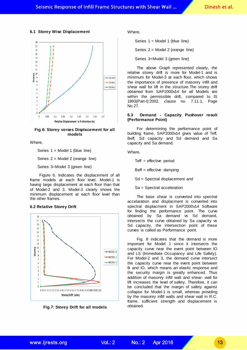
6.1 Storey Wise Displacement
Fig 6: Storey verses Displacement for all models
Where,
Series 1 = Model 1 (blue line)
Series 2 = Model 2 (orange line)
Series 3=Model 3 (green line)
Figure 6. Indicates the displacement of all frame models at each floor level. Model-1 is having large displacement at each floor than that
of Model-2 and 3. Model-3 clearly shows the minimum displacement at each floor level than the other frames.
6.2 Relative Storey Drift
Fig.7: Storey Drift for all models
Where,
Series 1 = Model 1 (blue line)
Series 2 = Model 2 (orange line)
Series 3=Model 3 (green line)
The above Graph represented clearly, the relative storey drift is more for Model-1 and is minimum for Model-3 at each floor, which shows
the importance of presence of masonry infill and shear wall for lift in the structure.The storey drift obtained from SAP2000v14 for all Models are
within the permissible drift, compared to IS 1893(Part-I):2002, clause no. 7.11.1, Page No.27.
6.3 Demand - Capacity Pushover result (Performance Point)
For determining the performance point of building frame, SAP2000v14 gives value of Teff,
Beff, Sd capacity and Sd demand and Sa capacity and Sa demand.
Where,
Teff = effective period
Beff = effective damping
Sd = Spectral displacement and
Sa = Spectral acceleration
The base shear is converted into spectral accelaration and displacment is converted into
spectral displacment in SAP2000v14 Software for finding the performance point. The curve obtained by Sa demand vs Sd demand,
intersects the curve obtained by Sa capacity vs Sd capacity, the intersection point of these curves is called as Performance point.
Fig. 8 indicates that the demand is more important for Model 1 since it intersects the
capacity curve near the event point between IO and LS (Immediate Occupancy and Life Safety). For Model-2 and 3, the demand curve intersect
the capacity curve near the event point between B and IO, which means an elastic response and the security margin is greatly enhanced. Thus
addition of masonry infill wall and shear- wall for lift increases the level of safety. Therefore, it can be concluded that the margin of safety against
collapse for Model-1 is small, whereas providing by the masonry infill walls and shear wall in R.C. frame, sufficient strength and displacement is obtained.
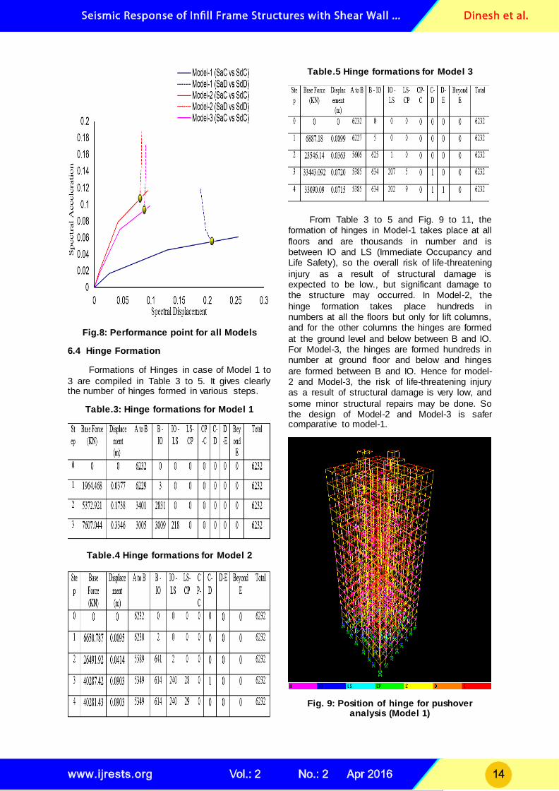
Fig.8: Performance point for all Models
6.4 Hinge Formation
Formations of Hinges in case of Model 1 to
3 are compiled in Table 3 to 5. It gives clearly the number of hinges formed in various steps.
Table.3: Hinge formations for Model 1
Table.4 Hinge formations for Model 2
Table.5 Hinge formations for Model 3
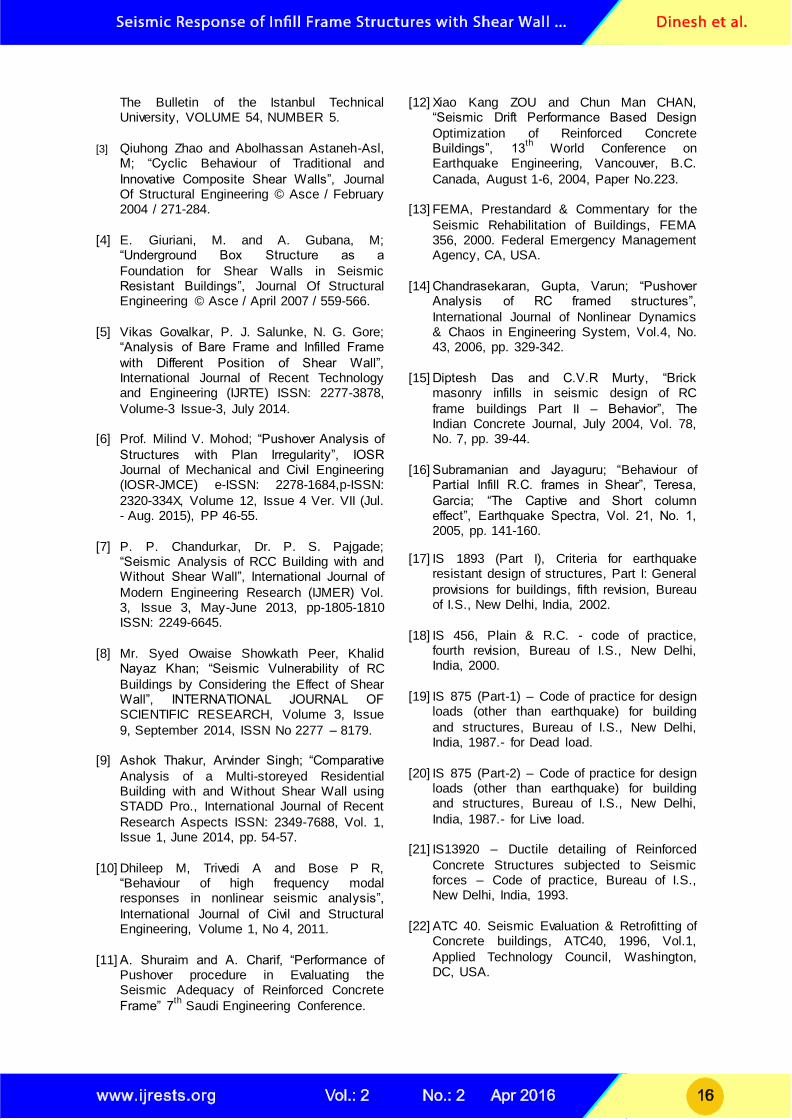
From Table 3 to 5 and Fig. 9 to 11, the formation of hinges in Model-1 takes place at all
floors and are thousands in number and is between IO and LS (Immediate Occupancy and Life Safety), so the overall risk of life-threatening
injury as a result of structural damage is expected to be low., but significant damage to the structure may occurred. In Model-2, the
hinge formation takes place hundreds in numbers at all the floors but only for lift columns, and for the other columns the hinges are formed
at the ground level and below between B and IO. For Model-3, the hinges are formed hundreds in number at ground floor and below and hinges
are formed between B and IO. Hence for model-2 and Model-3, the risk of life-threatening injury as a result of structural damage is very low, and
some minor structural repairs may be done. So the design of Model-2 and Model-3 is safer comparative to model-1.
Fig. 9: Position of hinge for pushover analysis (Model 1)
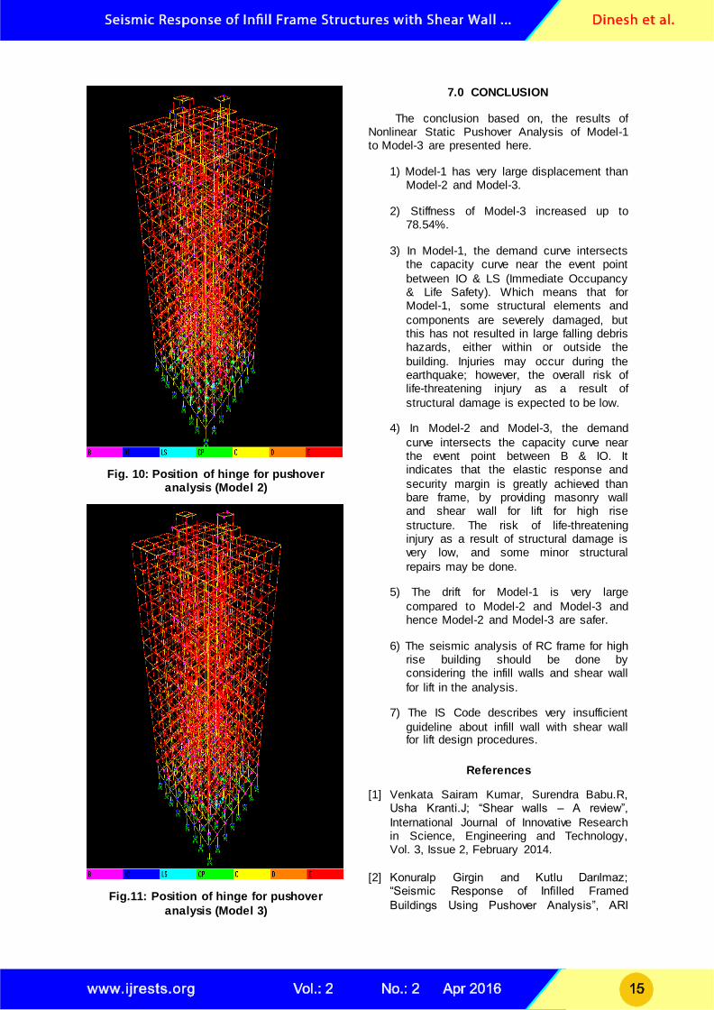
Fig. 10: Position of hinge for pushover analysis (Model 2)
Fig.11: Position of hinge for pushover
analysis (Model 3)
7.0 CONCLUSION
The conclusion based on, the results of Nonlinear Static Pushover Analysis of Model-1 to Model-3 are presented here.
1) Model-1 has very large displacement than Model-2 and Model-3.
2) Stiffness of Model-3 increased up to 78.54%.
3) In Model-1, the demand curve intersects the capacity curve near the event point
between IO & LS (Immediate Occupancy & Life Safety). Which means that for Model-1, some structural elements and
components are severely damaged, but this has not resulted in large falling debris hazards, either within or outside the
building. Injuries may occur during the earthquake; however, the overall risk of life-threatening injury as a result of
structural damage is expected to be low.
4) In Model-2 and Model-3, the demand
curve intersects the capacity curve near the event point between B & IO. It indicates that the elastic response and
security margin is greatly achieved than bare frame, by providing masonry wall and shear wall for lift for high rise
structure. The risk of life-threatening injury as a result of structural damage is very low, and some minor structural
repairs may be done.
5) The drift for Model-1 is very large
compared to Model-2 and Model-3 and hence Model-2 and Model-3 are safer.
6) The seismic analysis of RC frame for high rise building should be done by considering the infill walls and shear wall
for lift in the analysis.
7) The IS Code describes very insufficient
guideline about infill wall with shear wall for lift design procedures.
References
[1] Venkata Sairam Kumar, Surendra Babu.R, Usha Kranti.J; “Shear walls – A review”,
International Journal of Innovative Research in Science, Engineering and Technology, Vol. 3, Issue 2, February 2014.
[2] Konuralp Girgin and Kutlu Darılmaz;
“Seismic Response of Infilled Framed
Buildings Using Pushover Analysis”, ARI
The Bulletin of the Istanbul Technical University, VOLUME 54, NUMBER 5.
[3] Qiuhong Zhao and Abolhassan Astaneh-Asl,
M; “Cyclic Behaviour of Traditional and
Innovative Composite Shear Walls”, Journal Of Structural Engineering © Asce / February 2004 / 271-284.
[4] E. Giuriani, M. and A. Gubana, M;
“Underground Box Structure as a
Foundation for Shear Walls in Seismic Resistant Buildings”, Journal Of Structural Engineering © Asce / April 2007 / 559-566.
[5] Vikas Govalkar, P. J. Salunke, N. G. Gore;
“Analysis of Bare Frame and Infilled Frame
with Different Position of Shear Wall”, International Journal of Recent Technology and Engineering (IJRTE) ISSN: 2277-3878,
Volume-3 Issue-3, July 2014.
[6] Prof. Milind V. Mohod; “Pushover Analysis of
Structures with Plan Irregularity”, IOSR Journal of Mechanical and Civil Engineering (IOSR-JMCE) e-ISSN: 2278-1684,p-ISSN:
2320-334X, Volume 12, Issue 4 Ver. VII (Jul. - Aug. 2015), PP 46-55.
[7] P. P. Chandurkar, Dr. P. S. Pajgade; “Seismic Analysis of RCC Building with and Without Shear Wall”, International Journal of
Modern Engineering Research (IJMER) Vol. 3, Issue 3, May-June 2013, pp-1805-1810 ISSN: 2249-6645.
[8] Mr. Syed Owaise Showkath Peer, Khalid
Nayaz Khan; “Seismic Vulnerability of RC
Buildings by Considering the Effect of Shear Wall”, INTERNATIONAL JOURNAL OF SCIENTIFIC RESEARCH, Volume 3, Issue
9, September 2014, ISSN No 2277 – 8179.
[9] Ashok Thakur, Arvinder Singh; “Comparative
Analysis of a Multi-storeyed Residential Building with and Without Shear Wall using STADD Pro., International Journal of Recent
Research Aspects ISSN: 2349-7688, Vol. 1, Issue 1, June 2014, pp. 54-57.
[10] Dhileep M, Trivedi A and Bose P R, “Behaviour of high frequency modal responses in nonlinear seismic analysis”,
International Journal of Civil and Structural Engineering, Volume 1, No 4, 2011.
[11] A. Shuraim and A. Charif, “Performance of Pushover procedure in Evaluating the Seismic Adequacy of Reinforced Concrete
Frame” 7th
Saudi Engineering Conference.
[12] Xiao Kang ZOU and Chun Man CHAN, “Seismic Drift Performance Based Design
Optimization of Reinforced Concrete Buildings”, 13
th World Conference on
Earthquake Engineering, Vancouver, B.C.
Canada, August 1-6, 2004, Paper No.223.
[13] FEMA, Prestandard & Commentary for the
Seismic Rehabilitation of Buildings, FEMA 356, 2000. Federal Emergency Management Agency, CA, USA.
[14] Chandrasekaran, Gupta, Varun; “Pushover
Analysis of RC framed structures”,
International Journal of Nonlinear Dynamics & Chaos in Engineering System, Vol.4, No. 43, 2006, pp. 329-342.
[15] Diptesh Das and C.V.R Murty, “Brick
masonry infills in seismic design of RC
frame buildings Part II – Behavior”, The Indian Concrete Journal, July 2004, Vol. 78, No. 7, pp. 39-44.
[16] Subramanian and Jayaguru; “Behaviour of
Partial Infill R.C. frames in Shear”, Teresa,
Garcia; “The Captive and Short column effect”, Earthquake Spectra, Vol. 21, No. 1, 2005, pp. 141-160.
[17] IS 1893 (Part I), Criteria for earthquake resistant design of structures, Part I: General
provisions for buildings, fifth revision, Bureau of I.S., New Delhi, India, 2002.
[18] IS 456, Plain & R.C. - code of practice, fourth revision, Bureau of I.S., New Delhi, India, 2000.
[19] IS 875 (Part-1) – Code of practice for design
loads (other than earthquake) for building
and structures, Bureau of I.S., New Delhi, India, 1987.- for Dead load.
[20] IS 875 (Part-2) – Code of practice for design loads (other than earthquake) for building and structures, Bureau of I.S., New Delhi,
India, 1987.- for Live load.
[21] IS13920 – Ductile detailing of Reinforced
Concrete Structures subjected to Seismic forces – Code of practice, Bureau of I.S., New Delhi, India, 1993.
[22] ATC 40. Seismic Evaluation & Retrofitting of
Concrete buildings, ATC40, 1996, Vol.1,
Applied Technology Council, Washington, DC, USA.
Authors Biography
Mr. D.M. Pandit pursuing ME
in structural engineering in PES college of engineering
BAMU, University Aurangabad India.
Mr. Rahul D. Pandit obtained PG in BAMU Aurangabad
University. His area of specialization is Structural Engineering. He has Published
8 research papers in International Journals & 1
papers in international conferences. Is a assistant professor in PES college of
engineering Aurangabad. Is a guide for PG students.
Dr. Abhijeet P. Wadekar is a principal of PES college of Engineering Aurangabad. He
has Published 8 research papers in International Journals &1 papers in international
conferences. Is a paper reviewer for BAMU university Aurangabad. His specialization is structural engineering. Is a
guide for PhD scholars.