Embed Size (px)
Citation preview

INTERNATIONAL JOURNAL OF CIVIL AND STRUCTURAL ENGINEERING
Volume 1, No 4, 2010
© Copyright 2010 All rights reserved Integrated Publishing services
Research article ISSN 0976 – 4399
749
Seismic performance of hybrid fibre reinforced Beam - Column joint Perumal.P
1, Thanukumari.B
2
1- Professor and Head, Department of Civil Engineering, Government College of
Engineering, Salem, TamilNadu, India
2- Research Scholar, Assistant Professor and Head, Department of Civil Engineering,
Cape Institute of Technology, Levengipuram, Tirunelveli District,amil Nadu, India.
doi:10.6088/ijcser.00202010063
ABSTRACT
High Strength Concrete has become a very popular construction material which is
directly related to recent development in concrete technology. The brittle nature of this
High Strength Concrete results in sudden unpredictable failure. By using special hybrid
fibre combinations of steel and polypropylene fibres, the explosive failure behaviour of
High Strength Concrete (HSC) may be avoided. The main objective of this study is to
investigate the effect of different proportions of hybrid fibre combinations (1.5% of steel
fibre and 0 to 0.4% of polypropylene fibre) at the joint of exterior beam-column
connections subjected to earthquake loading using M60 concrete. The hybrid fibre
combinations of 1.5% of steel fibre and 0.2% of polypropylene fibre have best
performance considering the strength, energy dissipation capacity and ductility factor. An
attempt has been made to develop a new model by slightly modifying the previous
models available in the literature for the joint shear strength. The proposed model was
found to compare satisfactorily with the test results.
Keywords: High strength concrete, hysteresis, hybrid, energy absorption and beam
column joint.
1. Introduction
The recent earthquakes revealed the importance of the design of reinforced concrete (RC)
structures with ductile behaviour. Ductility can be described as the ability of reinforced
concrete cross sections, elements and structures to absorb the large energy released
during earthquakes without losing their strength under large amplitude and reversible
deformations. Generally, the beam-column joints of a RC frame structure subjected to
cyclic loads such as earthquakes experience large internal forces. Conventional concrete
looses its tensile resistance after formation of cracks. However, fibre concrete can sustain
a portion of its resistance following cracking to resist more cycles of loading.
Development of HSC is directly related to a number of recent technological
developments. HSC is developed by using superplasticizer, micro fillers like silica fume
and flyash and fibres of different types. The specific use of these micro fillers leads to a
strengthening of the cement matrix as well as an improvement of density and surface
abrasion resistance. Unfortunately the behaviour of the HSC is very brittle. The
improvement of compressive strength is followed by a very strong bond in the interaction
INTERNATIONAL JOURNAL OF CIVIL AND STRUCTURAL ENGINEERING
Volume 1, No 4, 2010
© Copyright 2010 All rights reserved Integrated Publishing services
Research article ISSN 0976 – 4399
750
zone of aggregate and cement matrix. The weakest components in the high strength
concrete structure are the aggregate, while these are the interaction zones in the normal
strength concrete. The HSC structures fall suddenly without an announcement by cracks
and the fracture zone is very smooth. This leads to a well-known steep descending branch
of the stress-strain curve. In practice only few methods are known to improve the
ductility of HSC structural members under compressive forces. The closely spaced ties
are one of the examples. Instead of using this method the main aim of the present
research programme is to strengthen the material itself to avoid disadvantageous
concerning costs and workability. In this article, the experimental study is made by using
the fibres to increase the ductility in the beam-column joint, which is the most critical
region during earthquake.
2. Research Objectives
This paper reports experimental study carried out to investigate the behaviour of exterior
beam column joint made of hybrid fibre (combinations of steel and polypropylene fibres)
reinforced concrete. In the previous investigations the amount of steel fibres, type and
aspect ratio, amount of synthetic fibers have been separately taken into consideration as
experimental parameters. In the present study five sets of high strength concrete
specimens representing an exterior beam column joint subjected to reversed cyclic
loading were tested under displacement controlled loading. The specimens were
designated as per the Table 1. The first specimen was cast without seismic detailing
(designed as per IS 456-2000).
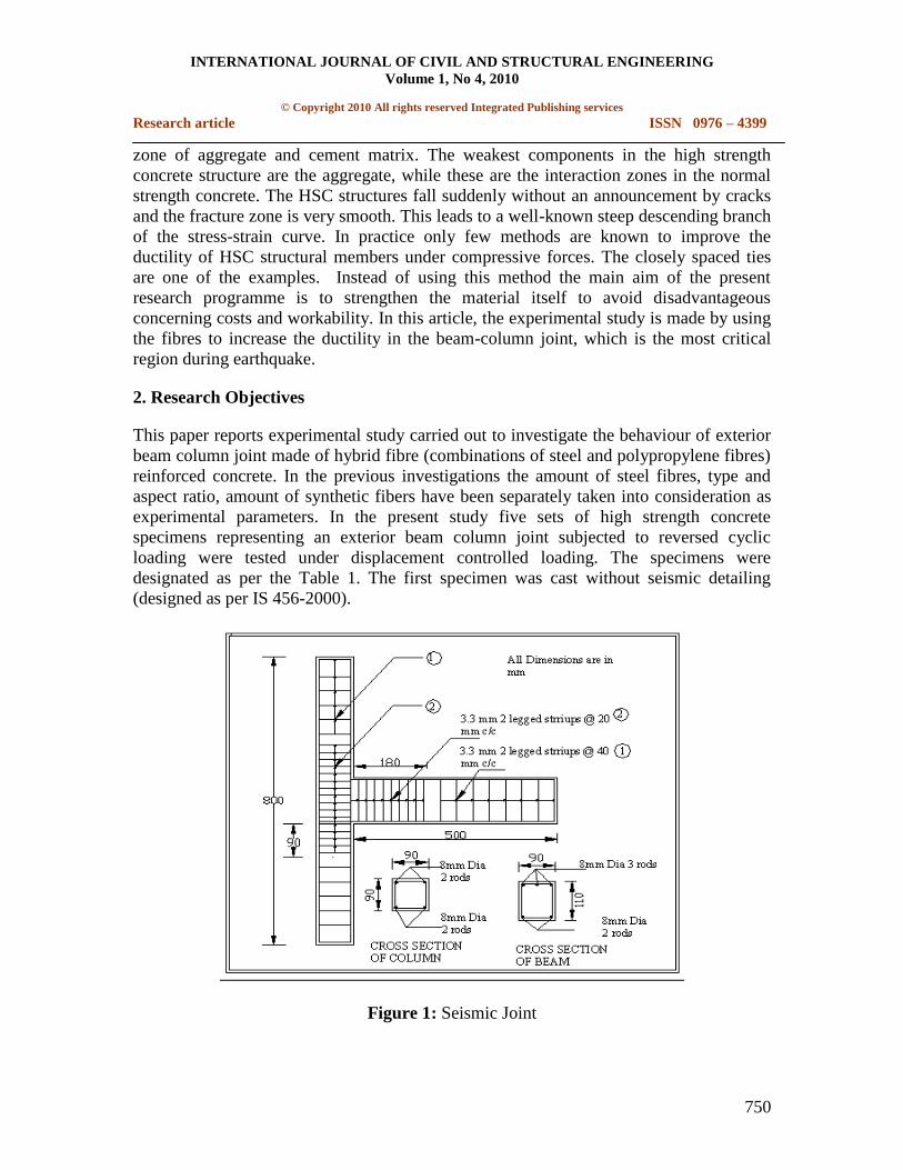
Figure 1: Seismic Joint

INTERNATIONAL JOURNAL OF CIVIL AND STRUCTURAL ENGINEERING
Volume 1, No 4, 2010
© Copyright 2010 All rights reserved Integrated Publishing services
Research article ISSN 0976 – 4399
751
The second specimen was cast as per seismic detailing as per the requirements of IS Code
13920:1993. Figure 1 shows the beam-column joint with seismic detailing. The
remaining three specimens were designed as like the first one but incorporating hybrid
fibre in the joint region. Figure 2 shows the beam-column joint without seismic detailing
with hybrid fibre reinforced concrete in the joint region. Hybrid fibre combination was
mixed in the range of 1.5% of steel fibre and 0 to 0.4% of polypropylene fibre with an
increment of 0.2 %.
Figure 2: Fibre Joint
Table 1: Details of the Test specimens
Specimen
Idetification
III O2
III S2
III F12
III F 22
III F32
Detailing of
Lateral
Reinforcement
Without
Seismic
Detailing
With
Seismic
Detailing
Without
Seismic
Detailing
Without
Seismic
Detailing
Without
Seismic
Detailing
% of Steel fibre -- -- 1.5 1.5 1.5
% of
Polypropylene
Fibre
--
--
0
0.2
0.4

INTERNATIONAL JOURNAL OF CIVIL AND STRUCTURAL ENGINEERING
Volume 1, No 4, 2010
© Copyright 2010 All rights reserved Integrated Publishing services
Research article ISSN 0976 – 4399
752
2.1 Material Properties and Concrete Mixes
Two different concrete mixes were used and they were given in Table 2. HPC mix
proportion for M 60 concrete was obtained based on the guidelines given in modified ACI
211 method. Table 2 presents the proportions of the two different concrete mixes used to
cast the test specimens. OPC 53 grade cement, river sand passing through 4.75mm IS
sieve and coarse aggregate less than 10 mm size were used for the investigation.
Corrugated steel fibres of diameter 0.5mm, length 30mm and aspect ratio 60 were used.
The polypropylene fibre used has a diameter of 0.008mm, length 20mm and of aspect
ratio 2500. Part of the cement was replaced by micro fillers such as silica fume (10 %)
and flyash (15%). In this study the cement was replaced by 10% of silica fume and 15%
of flyash. Superplasticizer was added to increase the workability of the concrete.
Table 2: Mix Proportions of High Strength Concrete (kg/m3
)
Mix Cement Fly
Ash
Silica
fume
Sand Coarse
Aggre
Gate
Water Super
Plasti
siser
Steel
Fibre
Polypropylene
fibre
HPC 463 88 36 656 962 209 10 lit - -
HPFRC 463 88 36 608 891 207 11.75 lit 117.5 0,1.82&3.64
3. Experimental Setup and Procedure
Each specimen was tested under reversed cyclic loading in the loading frame. The
general arrangement of the experimental setup is shown in Figure 3. The reversed cyclic
load was applied by using one screw jack for giving downward displacement and one
hydraulic jack for giving upward displacement at the end of the beam at a distance of
50mm from the beam end.
INTERNATIONAL JOURNAL OF CIVIL AND STRUCTURAL ENGINEERING
Volume 1, No 4, 2010
© Copyright 2010 All rights reserved Integrated Publishing services
Research article ISSN 0976 – 4399
753
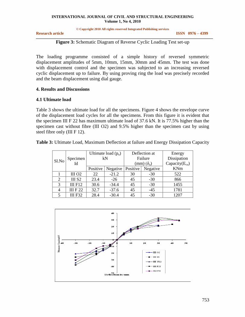
Figure 3: Schematic Diagram of Reverse Cyclic Loading Test set-up
The loading programme consisted of a simple history of reversed symmetric
displacement amplitudes of 5mm, 10mm, 15mm, 30mm and 45mm. The test was done
with displacement control and the specimen was subjected to an increasing reversed
cyclic displacement up to failure. By using proving ring the load was precisely recorded
and the beam displacement using dial gauge.
4. Results and Discussions
4.1 Ultimate load
Table 3 shows the ultimate load for all the specimens. Figure 4 shows the envelope curve
of the displacement load cycles for all the specimens. From this figure it is evident that
the specimen III F 22 has maximum ultimate load of 37.6 kN. It is 77.5% higher than the
specimen cast without fibre (III O2) and 9.5% higher than the specimen cast by using
steel fibre only (III F 12).
Table 3: Ultimate Load, Maximum Deflection at failure and Energy Dissipation Capacity
Sl.No Specimen
Id
Ultimate load (pu)
kN
Deflection at
Failure
(mm) (δu)
Energy
Dissipation
Capacity(Ecu)
KNm Positive Negative Positive Negative
1 III O2 22 -21.2 30 -30 522
2 III S2 23.4 -26 45 -30 866
3 III F12 30.6 -34.4 45 -30 1455
4 III F 22 32.7 -37.6 45 -45 1781
5 III F32 28.4 -30.4 45 -30 1207

INTERNATIONAL JOURNAL OF CIVIL AND STRUCTURAL ENGINEERING
Volume 1, No 4, 2010
© Copyright 2010 All rights reserved Integrated Publishing services
Research article ISSN 0976 – 4399
754
Figure 4: Overall Load Displacement curve for all test specimens
4.2 Energy Dissipation Capacity
Table 3 shows the energy dissipation capacity of all the specimens. Figure 5 shows the
hysteresis loop for the specimen III F22. Figure 6 shows the energy dissipation capacity
of all the specimens. From this figure it is noted that the specimen III F22 has the
maximum energy dissipating capacity. It is 241% higher than the specimen without fibre
(III O2) and 22.5% higher than the specimen with steel fibre only (III F12).
Figure 5: Load Displacement Plot For III F 22
Figure 6: Energy Dissipation Capacity
4.3 Experimental Joint Shear stress
For the exterior beam-column joint the horizontal and vertical joint shear stresses (τjh, τjv)
can be calculated using the following formula (Murty et al. 2003)

INTERNATIONAL JOURNAL OF CIVIL AND STRUCTURAL ENGINEERING
Volume 1, No 4, 2010
© Copyright 2010 All rights reserved Integrated Publishing services
Research article ISSN 0976 – 4399
755
τjh = hA core
H b b b
b c
L L 0.5D
d L
and (1)
τjv = b c b
v
c c
L 0.5D L D1
A core L d
cH
(2)
ACI 318 specifies the limit of joint shear stress as k√ 'cf Mpa, where 'cf is the cylinder
compressive strength, in Mpa. The factor k depends on the confinement provided by the
members framing into the joint; k is taken as 1.67, 1.25 and 1.0 for interior, exterior and
corner joints respectively.
Table 4: Ultimate Shear capacity of the Joint using M60 Concrete
Sl.
No
Specimen
Id
'cf
N/mm2
Ultimate
Load
kN
Horizontal
Shear stress
τjh, in
kN/mm2
Vertical
Shear stress
τjv in kN/mm2
Limiting Shear
stress as per
ACI= 1.0 'cf
kN/mm2
τjh, / τACI
1 III O2 61.2 22 13.2 11.70 7.82 1.69
2 III S2 61.2 26 15.6 13.83 7.82 1.99
3 III F12 66.9 34.4 20.64 18.29 8.18 2.52
4 III F 22 69.3 37.6 22.56 20.00 8.32 2.71
5 III F32 62.8 30.4 18.24 16.17 7.92 2.30
Table 4 shows the horizontal and vertical shear stresses induced in the joint region, and
code prescribed limiting shear stress. From this table it is observed that the specimen III
F22 has maximum horizontal and vertical shear stresses compared to all the other
specimens. The value of factor k is 1.69 and 1.99 for ordinary and seismic specimen
respectively and ranges from 2.3 to 2.71 for specimen cast by using fibre in the joint
region.
This value is greater than the code prescribed value. The code prescribed value is only for
normal concrete without fibre. Murthy et al., (2003) have reported that the improvements
in the joint reinforcement details and longitudinal bar anchorages caused the joints to
sustain larger shear stress values (1.25√fc to 1.79√fc) than the code specified limiting
values. In another study Kurose et al. (1988) reported that even without joint
reinforcement shear stress between 1.16√fc and 1.83√fc Mpa were developed prior to
beam hinging. Hence in the present study the increase in limiting shear stress may be due
to the addition of fibre in the joint region.
4.4 Theoretical Shear Strength of the Joint

INTERNATIONAL JOURNAL OF CIVIL AND STRUCTURAL ENGINEERING
Volume 1, No 4, 2010
© Copyright 2010 All rights reserved Integrated Publishing services
Research article ISSN 0976 – 4399
756
The joint shear strength can be calculated theoretically. It comprises the four
components: shear strength of plain concrete, shear strength resisted by longitudinal steel,
shear strength of lateral reinforcement and shear strength of fibre reinforced concrete.
(th) can be calculated by using the following equation
c fib s l(th)
(V +V +V +V )=
jA (3)
VC = τc bb db (4)
'0.07(1 10 )c w cf (Liu, Cong, 2006) (5)
stw
b b
A
b d
(6)
sh yt
S
A f dV
S
(7)
fibV =
2f
f P j
f
lV V A
d
(8)
This equation was arrived based on the experimental results
l yV =0.87*f *Ast (9)
4.5 Prediction of Joint Shear Strength by developing a Model
An attempt has been made to predict shear strength of joints using the models available in
the literature proposed by Tsonos et al., 1992, Jiuru et al., 1992, and Ganesan et al., 2007.
4.5.1 Modification proposed
In order to account for the effect of hybrid fibre in the model, a regression analysis was
carried out. A parameter Fc was introduced to account for the combined effect of hybrid
fibres compressive strength of concrete, and modulus of rupture of concrete is given by
'
f f p 1+ V *A V cc
cr
fF
f
(10)
(exp) = (th.)τ * ( 0.04 Fc + 1.466) (11)
Where (th.)τ is given by Equation (3)
INTERNATIONAL JOURNAL OF CIVIL AND STRUCTURAL ENGINEERING
Volume 1, No 4, 2010
© Copyright 2010 All rights reserved Integrated Publishing services
Research article ISSN 0976 – 4399
757
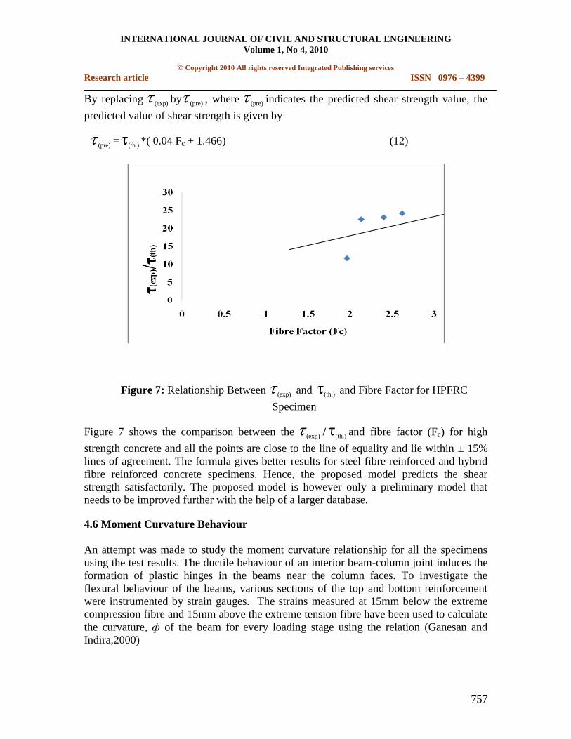
By replacing (exp) by (pre) , where (pre) indicates the predicted shear strength value, the
predicted value of shear strength is given by
(pre) = (th.)τ *( 0.04 Fc + 1.466) (12)
Figure 7: Relationship Between (exp) and (th.)τ and Fibre Factor for HPFRC
Specimen
Figure 7 shows the comparison between the (exp) / (th.)τ and fibre factor (Fc) for high
strength concrete and all the points are close to the line of equality and lie within ± 15%
lines of agreement. The formula gives better results for steel fibre reinforced and hybrid
fibre reinforced concrete specimens. Hence, the proposed model predicts the shear
strength satisfactorily. The proposed model is however only a preliminary model that
needs to be improved further with the help of a larger database.
4.6 Moment Curvature Behaviour
An attempt was made to study the moment curvature relationship for all the specimens
using the test results. The ductile behaviour of an interior beam-column joint induces the
formation of plastic hinges in the beams near the column faces. To investigate the
flexural behaviour of the beams, various sections of the top and bottom reinforcement
were instrumented by strain gauges. The strains measured at 15mm below the extreme
compression fibre and 15mm above the extreme tension fibre have been used to calculate
the curvature, ф of the beam for every loading stage using the relation (Ganesan and
Indira,2000)

INTERNATIONAL JOURNAL OF CIVIL AND STRUCTURAL ENGINEERING
Volume 1, No 4, 2010
© Copyright 2010 All rights reserved Integrated Publishing services
Research article ISSN 0976 – 4399
758
Ф =
t b
b
e e
d a
(13)
The values of moment M were calculated using the experimental values of load and lever
arm. Table 5 shows the moment, curvature ductility at peak load and yield load. These
values of M and Ф were used to obtain moment-curvature plots for the joint.
Table 5: Moment and Curvature Ductility Factor
Sl.No Specimen
Id
(Curvature at
peak load)
210X 1
m
(Curvature at yield
load)
210X 1
m
Curvature
Ductility
Factor
Moment at
Peak Load
kNmm
1 III O2 4.0927 3.0772 1.33 9900
2 III S2 5.4159 3.0772 1.76 11700
3 III F12 9.4373 3.0443 3.1 15480
4 III F22 10.828 3.0416 3.56 16920
5 III F32 11.472 3.0510 3.76 13680
4.7 Curvature Ductility Factor
The capacity of the member to deform beyond its initial yield deformations with
minimum loss of strength and stiffness depends upon the ductility factor which is
defined as the ratio of the ultimate deformation to its yield deformation at first yield.
Ductility may be defined easily in the case of elastoplastic behaviour. Ductility factors in
beam-column joint have been defined in terms curvature at critical section and is
(Ganesan and Indira,2000)
Curvature ductility factor = u
y
Ф
Ф (14)
yФ =curvature at yield =
y
s b
f
E d x (15)
The curvature at peak load and curvature ductility factor thus calculated for all M60
concrete specimens are given in Table 5. From the table it may be noted that the hybrid
fibre reinforced specimens have better values of ductility factor than the other specimens.
5. Conclusions
1. The hybrid fibre reinforced concrete joints undergo large displacements without
developing wider cracks when compared to SFRHPC and HPC joints.
uФyФ

INTERNATIONAL JOURNAL OF CIVIL AND STRUCTURAL ENGINEERING
Volume 1, No 4, 2010
© Copyright 2010 All rights reserved Integrated Publishing services
Research article ISSN 0976 – 4399
759
2. The fibres are effective in resisting deformation at all stages of loading from first
crack to failure.
3. The specimen III F22 which was formed by using hybrid fibre reinforced concrete
in the joint region, consisting of 1.5% of steel fibre and 0.2% of polypropylene
fibre exhibited excellent strength, deformation capacity, energy dissipation
capacity and damage tolerance. It also has minor joint damage.
4. The addition of polypropylene fibre increases the energy dissipation capacity,
ultimate load, when the dosage of polypropylene fibre is 0.2 %.
5. The specimen III F32 (1.5% of steel fibre +0.4% of polypropylene fibre) has the
maximum curvature ductility factor. The excess polypropylene fibre increases the
ductility but at this % the ultimate load and energy dissipation capacity is also
reduced.
6. It is possible to reduce the congestion of steel reinforcement in beam-column joint
by replacing part of ties in columns by steel and synthetic fibres and thereby
reducing the cost of construction.
7. For analysing and predicting the joint shear strength, the joint shear strength
formula has been developed by considering volume of steel and polypropylene
fibre in the previously developed models.
Notations
Lb - Length of beam
Lc - Length of column
Db - Total depth of beam
Dc - Total depth of column
db - Effective depth of beam
dc - Effective depth of column
Ahcore - horizontal cross sectional area of the joint core resisting the
horizontal joint shear
Avcore - vertical cross sectional area of the joint core resisting the vertical
shear
Ast - Area of beam longitudinal reinforcement

INTERNATIONAL JOURNAL OF CIVIL AND STRUCTURAL ENGINEERING
Volume 1, No 4, 2010
© Copyright 2010 All rights reserved Integrated Publishing services
Research article ISSN 0976 – 4399
760
Ash - Area of shear reinforcement
S - Spacing of shear reinforcement
fyt - Characteristics strength of lateral reinforcement
fl - length of the steel fibre
fd - diameter of the steel fibre
fA - Aspect Ratio of the steel fibre
Vf - percentage of volume of steel fibre
Vp - percentage of volume of polypropylene fibre
jA - area of joint core
τc - Shear stress in concrete
VC - Shear resisted by concrete
VS - Shear resisted by strriups
fibV - Shear resisted by fibre
Vl - Shear resisted by longitudinal reinforcement
'cf - Cylindrical compressive strength of concrete
fcr - modulus of rupture of concrete
(exp) - Experimental value of ultimate shear stress
(pre) - Predicted value of ultimate shear stress
(th.)τ - Theoretical value of ultimate shear stress
te
- Strain in the top reinforcement
be
- Strain in the bottom reinforcement
a - Compressive reinforcement cover

INTERNATIONAL JOURNAL OF CIVIL AND STRUCTURAL ENGINEERING
Volume 1, No 4, 2010
© Copyright 2010 All rights reserved Integrated Publishing services
Research article ISSN 0976 – 4399
761
uФ
- Curvature at peak load
yФ
- Curvature at yield
yf
- yield strength of main reinforcement
sE - Modulus of elasticity of steel
x - depth of neutral axis
6. References
1. Alexandors and Tsonos.G., 2007, Cyclic Load Behavior of Reinforced Concrete
Beam-Column Sub Assemblages of Modern Structures. ACI Structural Journal,
104(4), pp 468-478.
2. Amir A. Mirsayah and Nemkumar Banthia. 2002. Shear Strength of Steel Fibre-
Reinforced Concrete. ACI Materials Journal, 99(5), pp 473-479.
3. Andre Filatrault, Karim Ladicani, and Bruno Massicotte. 1994. Seismic
Performance of Code Designed Fibre Reinforced Concrete Joints. ACI Structural
Journal, 91(5), pp 564-571.
4. Andre Filiatrault, Sylvain Pineau, and Jules Houde. 1995. Seismic Behaviour of
Steel Fibre Reinforced Concrete Interior Beam-Column Joints. ACI Structural
Journal, 92(5), 543-551.
5. Asha, P. and Sundararajan, R. 2006. Evaluation of seismic resistance of exterior
beam-column joints with detailing as per IS 13920:1993. The Indian concrete
Journal, 80(2), pp 29-34.
6. Au, F.T.K., Huang, K. and Pam, H.J., 2005. Diagonally- Reinforced Beam-
Column Joints Reinforced Under Cyclic loading. Structures and Buildings, 158,
pp 21-40.
7. Ganesan, N. and Indira, P.V., 2000. Latex modified SFRC beam-column joints
subjected to cyclic loading. The Indian Concrete Journal, 74(7), pp 416-420.
8. Ganesan, N., Indira, P.V and Ruby Abraham., 2007. Fibre Reinforced High
Performance Concrete Beam-Column Joints Subjected to Cyclic Loading.ISTE
Journal of Earthquake Technology, 44(4), pp 445-456.
9. Gustavo J. Parra- Montesinos. 2005. High-Performance Fibre Reinforced Cement
Composites an Alternative for Seismic Design of Structures. ACI Structural
Journal, 102(5), pp 668-673.

INTERNATIONAL JOURNAL OF CIVIL AND STRUCTURAL ENGINEERING
Volume 1, No 4, 2010
© Copyright 2010 All rights reserved Integrated Publishing services
Research article ISSN 0976 – 4399
762
10. Indian Standard Plain and Reinforced Concrete Code of Practice IS 456:2000
Bureau of Indian Standards, New Delhi.
11. Indian Standard Ductile Detailing of reinforced Concrete Structures subjected to
Seismic Forces. Code of Practice: IS 13920-1993 (Part 1):2002. Bureau of Indian
Standards, New Delhi.
12. Indian Standard Criteria for Earthquake resistant Design of Structures, Part I
Genaral Provisions and Buildings, IS 1893 (Part I) 2002 Bureau of Indian
Standards, New Delhi.
13. Jamal Shannag M, Nabeela Abu- Dyya and Ghazi Abu- Farsakh. 2006. Lateral
load Response of HighPerformence Fibre Reinforced Concrete Beam-Column
Joints. ELSEVIER Journal of Construction and Building Materials 19, 500-508.
14. Lars Kutzing. 1997. Use of Fibre Hybrid to Incerase the ductility of High
Performance Concrete (HPC). Institute for Massivbau and Baustoffechnologie i
Gr.Universitat Leipzig,LACER No. 2, pp 125-134.
15. Liu and Cong. 2006. Seismic Behaviour of Beam-Column Joint Subassemblies
Reinforced with Steel fibres. A report submitted in partial fulfilment of the
requirements for the degree of Master of Engineering in the University of
Canterbury.
16. Murty, C.V.R., Durgesh C. Rai, Bajpai, K.K and. Jain, K. 2003. Effectiveness of
Reinforcement Details in Exterior Reinforced Concrete Beam-Column Joints for
Earthquake Resistance. ACI Structural Journal, 100(2), pp 149-156.
17. Shetty, M. S. ―Concrete Technology Theory and Practice‖. S.Chand &Company
Ltd, New Delhi, 1996.
18. Parviz Soroushian and Ziad Bayasi. 1991. Fibre Type Effects on the Performance
of Steel Fibre Reinforced Concrete. ACI Material Journal, 88(2),pp 129-134..
19. Paul, R.Gefken and Melvin, R.Ramey. 1989. Increased Joint Hoop Spacing in
Type 2 Seismic Joints Using Fibre Reinforced Concrete. ACI Structural Journal,
86(2),pp 168-172.
20. Tang Jiuru et al., 1992. Seismic behavior and shear strength of framed joint using
steel-fiber reinforced concrete. Journal of Structural Engineering, 118(2),pp 341-
358.
21. Thanukumari, B. and Perumal, P. 2009. An Experimental Study on the Behaviour
of M20 Concrete with Hybrid Fibre in Exterior Beam-Column Joints Subjected to
Reversed Cyclic Loading. IETECH Journal of Civil and Structures, 2(2), 065-070.

INTERNATIONAL JOURNAL OF CIVIL AND STRUCTURAL ENGINEERING
Volume 1, No 4, 2010
© Copyright 2010 All rights reserved Integrated Publishing services
Research article ISSN 0976 – 4399
763
22. Thanukumari, B. and Perumal, P. 2010. Behaviour of M60 Concrete Using Fibre
Hybrid in Exterior Beam-Column Joint Under Reversed Cyclic Loading. Asian
journal of civil engineering (building and housing), 11(2), pp 265-275.
23. Tsonos, A.G., Tegos, I.A. and Penelis, G.G. (1992). Seismic Resistance of Type 2
Exterior Beam-Column Joints Reinforced with Inclined Bars. ACI Structural
Journal, 89(1),pp 3–12.
********************
In this paper, it is envisaged to create a new composite material which can be derived
from the already existing non-degradable and hazardous waste materials. The new
composite material is a combination of Ordinary Portland cement and Dyeing Industry
Effluent Treatment plant Sludge (DIETP-S). It replaces the non availability of natural

INTERNATIONAL JOURNAL OF CIVIL AND STRUCTURAL ENGINEERING
Volume 1, No 4, 2010
© Copyright 2010 All rights reserved Integrated Publishing services
Research article ISSN 0976 – 4399
764
building materials such as sand and related aggregates. It is the method of extracting
wealth from the waste. Various compositions of mixtures are made in Phase I of the
research. The test results of different mixtures are analyzed. The economical composite,
1:1.7 having sufficient strength as per IS codes for Bricks was selected. The composite
mixture having high quality with low cost is selected for future use as a non-conventional
building material named as Synthetic Sludge Aggregate (SSA). This SSA is used to
manufacture synthetic fine aggregates. The fine aggregates are then used as replacement
of sand in various percentages is M20, M30 and M40 concrete and compressive strength
and split tensile strength characteristics are studied as per BIS standards. It is envisaged
that this composite material reduces the environmental hazards caused by dyeing
industries. There is an abundant scope for the use of this SSA in various construction and
development activities.
Keywords: Composite, Cement, Dyeing Industry Effluent Treatment Plant Sludge,
Synthetic Sludge Aggregate, Sand & Concrete
1. Introduction
DIETP-S is classified as hazardous waste, generated during the primary treatment of
textile effluents. Thousands of tonnes of sludge generated in the last ten years are piled
up at common and individual effluent treatment plants. The effluents generated are
treated at effluent treatment plants. 8.8-crore litres of effluents, after primary treatment in
effluent treatment plants, are being let out into the Noyyal River every day in Thiruppur
alone. One tonne of dewatered sludge is produced for every 500-1000 m3 of wastewater
treated. They all generate dried sludge amounting to an estimated 88 tonnes a day in
Thiruppur alone. The sludge, a highly hazardous chemical waste, is stored in open yards.
The industry also struggles to find a place for a landfill of this sludge. ―Landfill is not a
solution to pollution‖ as during rains the DIETP-S dissolves in rain water and leaches in
to the ground and storm runoff from these yards pollutes streams and rivers. DIETP-S
consists of dye waste, lime, ferrous sulphate, coagulant aids and polyelectrolyte, etc1.
DIETP-S used in the research contains chlorides of 36.85% and sulphate of 20.63%.
Cement is a widely used binding material in construction industry. It is used in mortar,
concrete, precast elements and even for manufacturing bricks. Compared to other binding
materials, cement is the cheapest one.
In this paper it is envisaged to create a new composite using ordinary Portland cement
and DIETP-S. The non dissolving mix having sufficient strength is obtained in phase-I of
the research and in phase-II, The composite is used as a replacement for sand in M20,
M30& M40 concrete. Concrete mix design is done by using the ACI Committee method.
Concrete5 is a most widely used material today. The versatility and mouldability of this
material, its high compressive strength has largely contributed to its widespread use.
Concrete has been in use throughout the civilized history of our mankind. As the

INTERNATIONAL JOURNAL OF CIVIL AND STRUCTURAL ENGINEERING
Volume 1, No 4, 2010
© Copyright 2010 All rights reserved Integrated Publishing services
Research article ISSN 0976 – 4399
765
technology advances, new ingredients are added to study the alteration in properties of
concrete with each ingredient. As each recipe created in kitchen has different tastes,
concrete also shows different extraordinary changes in properties with change in
ingredients.
The compressive strength of concrete is one of the most important and useful properties
of concrete. It is used as a qualitative measure for other properties of hardened concrete.
Compressive strength of concrete is generally determined by testing cubes made in Lab
or field. When concrete fails under compressive load, the failure is essentially a mixture
of crushing and shear failure. The compressive strength of concrete mainly depends on
water-cement ratio, aggregate strength, etc.
2. Review of literature/Theoretical Background of study
Ramesh Kumar, et al, has done extensive study on dye effluents in Perundurai. He says
that, Textile dyeing industries in Erode and Tirupur district of Tamilnadu (India)
discharge effluents ranging between 100 and 200m³/t of production. Dyeing is performed
by Jigger or advanced Soft Flow reactor process. Coloring of hosiery fabric takes place in
the presence of high concentration of sodium sulphate or sodium chloride (30 – 75 kg/m³)
in dye solutions.
Hilary Nath has produced block bricks from the primary sludge generated in the garment
washing process. The developed sludge brick was tested for the common parameter for a
building block. Comparing the test results with normal block brick, a higher compressive
strength was recorded in the sludge block brick.
Balasubramanian et al, has studied the potential reuse of textile effluent treatment plant
(ETP) sludge in building materials. The physio-chemical and engineering properties of a
composite textile sludge sample from the southern part of India have been studied.
Jewaratnam, Jegalakshimi did a detailed work on sludge from a waste water treatment
plant, the sludge in this work was dried and powdered and added to clay in various
proportions. A 8‖x31/2‖x1/2‖ size of samples were produced by using manual press
operated at 180 psi. The samples were dried in an oven at 105°C for 24 hours before
firing in a kiln at 1050°C using specific temperature program to optimize vitrification
process. The fired samples were evaluated for the thermal conductivity and sound barrier
characteristics were evaluated. The project is under progress.
Reddy Babu G, conducted the feasibility study of usage of sludge from sand beneficiation
treatment plant in the production of bricks. At 5% to 10% of replacement, the quality of
bricks is superior to the brick made from brick earth alone and can be used for superior
work of permanent nature.
Seshadri Sekhar, et al, studied the properties like Compressive Strength, Split Tensile
Strength and Flexural Strength of Self compacting concrete mix proportions ranging from
INTERNATIONAL JOURNAL OF CIVIL AND STRUCTURAL ENGINEERING
Volume 1, No 4, 2010
© Copyright 2010 All rights reserved Integrated Publishing services
Research article ISSN 0976 – 4399
766
M30 to M65 Grades of Concrete. An attempt also has been made to obtain a relationship
between the splitting tensile strength, Flexural Strength and Compressive strength by the
test results.
3. Research Objectives
In Phase I, a non-dissolving and economical composite is to be obtained.
The composite will be cast in bricks blocks and strength will be
ascertained as per BIS3&4
.
In Phase II, composite will be crushed to obtain SSA . The SSA would be
used as a replacement for sand in various ratios viz. 5%, 10%, 15% and
20% in M20, M30 and M40 concretes. Mix design will be as per ACI
Committee method. Compressive strength and split tensile strengths will
be evaluated as per BIS.
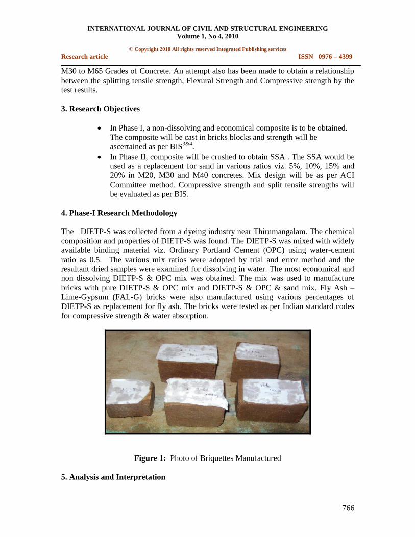
4. Phase-I Research Methodology
The DIETP-S was collected from a dyeing industry near Thirumangalam. The chemical
composition and properties of DIETP-S was found. The DIETP-S was mixed with widely
available binding material viz. Ordinary Portland Cement (OPC) using water-cement
ratio as 0.5. The various mix ratios were adopted by trial and error method and the
resultant dried samples were examined for dissolving in water. The most economical and
non dissolving DIETP-S & OPC mix was obtained. The mix was used to manufacture
bricks with pure DIETP-S & OPC mix and DIETP-S & OPC & sand mix. Fly Ash –
Lime-Gypsum (FAL-G) bricks were also manufactured using various percentages of
DIETP-S as replacement for fly ash. The bricks were tested as per Indian standard codes
for compressive strength & water absorption.
Figure 1: Photo of Briquettes Manufactured
5. Analysis and Interpretation

INTERNATIONAL JOURNAL OF CIVIL AND STRUCTURAL ENGINEERING
Volume 1, No 4, 2010
© Copyright 2010 All rights reserved Integrated Publishing services
Research article ISSN 0976 – 4399
767
Figure 2: Chart of Percentage Loss of Mass
Table 1: Percentage loss of mass in briquettes
Briquette Mix Percentage Loss of Mass
1:05 17.2
1:04 15.5
1:03 10.3
1:02 7.8
01:01.9 3.1
01:01.8 1.4
01:01.7 0
01:01.6 0
01:01.5 0
a) Inference from dissolution test: Various mixes of OPC & DIETP-S were tried viz.
1:5, 1:4, 1:3, 1:2, 1:1.9, 1:1.8, 1:1.7, 1:1.6 & 1:1.5. Out of these 1:1.7, 1:1.6 & 1:1.5
mix briquette samples did not dissolve in water and shape of sample did not
disintegrate. The mix 1:1.7 is taken for casting bricks as it is economical.
b) Manufacture of bricks: Bricks were moulded in 9‖x 4‖x3‖ moulds. Using various trial
mixes with water-cement ratio as 0.5. After 28 days curing, the bricks were tested as
per BIS. The results are shown in table I

INTERNATIONAL JOURNAL OF CIVIL AND STRUCTURAL ENGINEERING
Volume 1, No 4, 2010
© Copyright 2010 All rights reserved Integrated Publishing services
Research article ISSN 0976 – 4399
768
Figure 3: Photo of Bricks Manufactured
Table 2: Compressive Strength of Bricks and Cost Comparison
Mix details
Cost per
Brick
(Rs.)
Water
absorption
In %
Crushing
strength in
N/mm2
(7- days)
Crushing
strength in
N/mm2
(28- days)
OPC and DIETP-S ratio 1:1.5 7.0 2.97 9.067 13.24
OPC and DIETP-S ratio 1:1.7 6.84 2.96 7.463 10.37
OPC ,DIETP-S and sand ratio
1:1.7:2.1 4.22 3.22 8.576 11.07
OPC ,DIETP-S and sand ratio
1:1.7:3 4.04 3.59 5.487 7.41
OPC ,DIETP-S and sand ratio
1:1.7:3.5 3.73 3.41 5.373 7.15
FAL-G Based bricks 10%
DIETP- S 4.15 8.81 2.524 3.4
FAL-G Based bricks 15%
DIETP-S 4.31 11.50 2.216 2.79
FAL-G based bricks 20% ETP
sludge 4.38 14.80 3.770 5.95

INTERNATIONAL JOURNAL OF CIVIL AND STRUCTURAL ENGINEERING
Volume 1, No 4, 2010
© Copyright 2010 All rights reserved Integrated Publishing services
Research article ISSN 0976 – 4399
769
Figure 4: Comparison Chart of Bricks
c) Phase I – Results: The compressive strength of the bricks with only OPC – DIETP-S
mixes gave high strength but cost per brick is quite high and not marketable. The OPC
– DIETP-S – sand 1:1.7:3 mix showed appreciable reduction in strength when
compared to OPC – DIETP-S mixes, but the cost per brick is comparable to the cost of
other country bricks. It shows 28 days crushing strength as 7.41 N/mm2, which is
equivalent to second class brick as per IS-3495 (part – I)-1976.
6. Phase – II Research Methodology
The 1:1.7 mix bricks were broken down to obtain SSA. The SSA is used as replacement
for sand in various percentages 5%, 10%, 15% and 20% in concrete mixes M20, M30 and
M40. Mix design was done as per ACI Committee method. M20 is 1:2.88:3.16 with w/c
ratio 0.60. M30 Mix is 1:2.03:2.48 with w/c ratio 0.47. M40 Mix is 1:1.46:2.0 with w/c
ratio 0.38. Concrete cubes were created to study compressive strength for 3 days and 28
days. Cylinders were cast to study split tensile strength of concrete at 28 days. Tests were
conducted as per BIS.

INTERNATIONAL JOURNAL OF CIVIL AND STRUCTURAL ENGINEERING
Volume 1, No 4, 2010
© Copyright 2010 All rights reserved Integrated Publishing services
Research article ISSN 0976 – 4399
770
7. Phase-II Analysis and Interpretation
Table 3: Compressive Strength at 3days in N/mm2.
Mix / Mix ratios M20 M30 M40
Plain concrete(PL) 13.52 21.86 29.13
Concrete with 5% sand replacement by SSA (5%) 14.38 19.87 31.73
Concrete with 10% sand replacement by SSA (10%) 12.86 17.52 29.07
Concrete with 15% sand replacement by SSA (15%) 13.82 16.9 28.74
Concrete with 20% sand replacement by SSA (20%) 11.2 16.42 24.85
Table 4: Compressive strength at 28 days in N/mm2
Mix/ Mix ratios M20 M30 M40
Plain concrete(PL) 20.375 29.37 42.616
Concrete with 5% sand replacement by SSA (5%) 21.544 29.8 38.51
Concrete with 10% sand replacement by SSA (10%) 18.455 27.836 37.305
Concrete with 15% sand replacement by SSA (15%) 13.58 24.862 33.228
Concrete with 20% sand replacement by SSA (20%) 12.36 20.944 32.268
Figure 5: Comparison of 3 days compressive strength

INTERNATIONAL JOURNAL OF CIVIL AND STRUCTURAL ENGINEERING
Volume 1, No 4, 2010
© Copyright 2010 All rights reserved Integrated Publishing services
Research article ISSN 0976 – 4399
771
Figure 6: Comparison of 28 days compressive strength in N/mm2
Table 5: Split Tensile Strength at 28 Days in N/mm2
Mix/ Mix Ratios M20 M30 M40
Plain concrete (PL) 2.270 3.1975 3.2376
Concrete with 5% sand replacement by SSA (5%) 2.085 2.7889 3.68
Concrete with 10% sand replacement by SSA (10%) 2.3473 2.511 3.7702
Concrete with 15% sand replacement by SSA (15%) 2.2982 2.4572 3.5579
Concrete with 20% sand replacement by SSA (20%) 2.0821 2.3345 3.2663

INTERNATIONAL JOURNAL OF CIVIL AND STRUCTURAL ENGINEERING
Volume 1, No 4, 2010
© Copyright 2010 All rights reserved Integrated Publishing services
Research article ISSN 0976 – 4399
772
Figure 7: Comparison of 28 days split tensile strength in N/mm2
From the tables and charts it is evident that the compressive strength of the concrete
cubes decreases with increase in percentage of SSA. This may be due to the presence of
chlorides of 36.85% and sulphate of 20.63% in DIETP-S. Both chloride and sulphate are
deleterious to concrete. Hence SSA of 5% may be used in concrete as there is only very
mild variation in strength. From the charts we can clearly observe that the strength
actually increased at 5% of SSA.
8. Recommendations and findings
A composite is successfully obtained from the OPC and DIETP-S.
Bricks can be manufactured from the composite with strength of second class
bricks and their cost is comparable with bricks available in market.
New composite aggregate SSA is projected as replacement of already scantly
available sand.
SSA can be used only up to 5% as replacement of sand without affecting the
strength of concrete.
9. Limitation of the study
Only strength characteristics of the composite and concrete is studied.
Durability aspects of the composite will be considered in further research.
Environmental and economical impact of using this composite can be evaluated in
further research.

INTERNATIONAL JOURNAL OF CIVIL AND STRUCTURAL ENGINEERING
Volume 1, No 4, 2010
© Copyright 2010 All rights reserved Integrated Publishing services
Research article ISSN 0976 – 4399
773
10. Conclusions
A non Dissolving composite of mix 1:1.7 was manufactured successfully. The composite
was used for manufacturing bricks in first phase of the research. The bricks were found to
be economical and the compressive strength of bricks was similar to second class bricks
as per BIS. In phase II of the research, bricks were broken down to obtain SSA and the
SSA was used as replacement for sand in concrete mixes M20, M30 and M40.
Compressive strength of all the concrete mixes showed decline in strength with increase
in percentage of SSA. This may be due to the chloride and sulphates present in SSA.
Hence it is advisable to use only 5% of SSA as replacement of sand in concrete.
Commercial manufacture of bricks from the composite may also be undertaken after
doing durability study on the composite.
References
1 Balasubramaniana J., et al., (2005), ―Reuse of textile effluent treatment plant
sludge in building materials‖, Elsevier Ltd., online paper, 11 January 2005, pp. 1.
2 Hilary Nath (2006), ―Sludge-Bricks Development‖, Reach Journal, brandix
inspired solutions, Issue 3, pp. 6.
3 IS-3495 (part – I)-1976 –―Determination of compressive strength, Methods of test
of burnt clay bricks‖, Bureau of Indian Standards, New Delhi.
4 IS-3495 (part – II)-1976 -―Determination of water absorption, Methods of test of
burnt clay bricks‖, Bureau of Indian Standards, New Delhi.
5 IS-456-2000 – Plain and Reinforced concrete - Code of practice, Bureau of Indian
Standards, New Delhi.
6 Jewaratnam, et al., (2006) ―Waste Recovery from Industrial Sludge‖. University
of Malaya. Engineering e-Transaction, 1 (2). ISSN 1823-6379, pp. 5-8.
7 Ramesh Kumar M. and K. Saravanan, (2009) ―Recycling of Woven Fabric
Dyeing Wastewater Practiced in Perundurai Common Effluent Treatment Plant‖.
CCSE Journal, April 2009, Volume - 3, No – 4, pp 146
8 Ranganathan K., et al., (2006)―Recycling of wastewaters of textile dyeing
industries using advanced treatment technology and cost analysis‖—Case studies‖.
Conservation and recycling, Volume 50, Issue 3, May 2007, pp 306-318
9 Reddy Babu G, Mallikarjuna Rao K, Ramana Reddy IV (2005), ―Value addition
for sludge generated from sand beneficiation treatment plant‖. Dept Civil Engg.,
SVU Coll Engg, Tirupati. Nature Env. Polln. Techno, , pp 203-206

INTERNATIONAL JOURNAL OF CIVIL AND STRUCTURAL ENGINEERING
Volume 1, No 4, 2010
© Copyright 2010 All rights reserved Integrated Publishing services
Research article ISSN 0976 – 4399
774
10 Renganathan L (2009), ―Safe disposal of sludge, a problem‖, Online edition of
India's National Newspaper, The Hindu.
11 Seshadri Sekhar T. and Srinivasa Rao P., (2008) ―Relationship between
Compressive, Split Tensile, Flexural Strength of Self Compacted Concrete‖
International Journal of Mechanics and Solids, © Research India Publications,
ISSN 0973-1881 Vol.- 3 No.- 2, (2008) pp. 157–168.
12 Shetty M.S. (2005) ―Concrete technology theory and practice‖ S. Chand
publications, ISBN 81-219-0348-3, pp 257.