Embed Size (px)
Citation preview
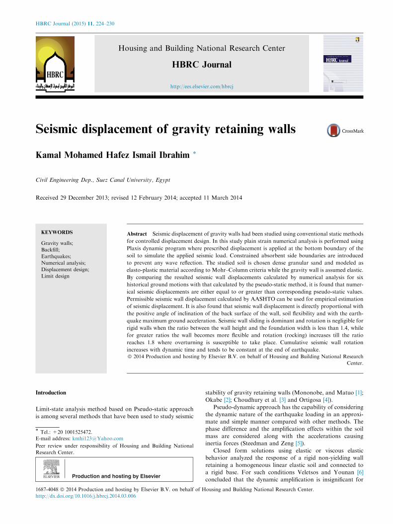
HBRC Journal (2015) 11, 224–230
Housing and Building National Research Center
HBRC Journal
http://ees.elsevier.com/hbrcj
Seismic displacement of gravity retaining walls
* Tel.: +20 1001525472.E-mail address: [email protected]
Peer review under responsibility of Housing and Building National
Research Center.
Production and hosting by Elsevier
1687-4048 ª 2014 Production and hosting by Elsevier B.V. on behalf of Housing and Building National Research Center.
http://dx.doi.org/10.1016/j.hbrcj.2014.03.006
Kamal Mohamed Hafez Ismail Ibrahim *
Civil Engineering Dep., Suez Canal University, Egypt
Received 29 December 2013; revised 12 February 2014; accepted 11 March 2014
KEYWORDS
Gravity walls;
Backfill;
Earthquakes;
Numerical analysis;
Displacement design;
Limit design
Abstract Seismic displacement of gravity walls had been studied using conventional static methods
for controlled displacement design. In this study plain strain numerical analysis is performed using
Plaxis dynamic program where prescribed displacement is applied at the bottom boundary of the
soil to simulate the applied seismic load. Constrained absorbent side boundaries are introduced
to prevent any wave reflection. The studied soil is chosen dense granular sand and modeled as
elasto-plastic material according to Mohr–Column criteria while the gravity wall is assumed elastic.
By comparing the resulted seismic wall displacements calculated by numerical analysis for six
historical ground motions with that calculated by the pseudo-static method, it is found that numer-
ical seismic displacements are either equal to or greater than corresponding pseudo-static values.
Permissible seismic wall displacement calculated by AASHTO can be used for empirical estimation
of seismic displacement. It is also found that seismic wall displacement is directly proportional with
the positive angle of inclination of the back surface of the wall, soil flexibility and with the earth-
quake maximum ground acceleration. Seismic wall sliding is dominant and rotation is negligible for
rigid walls when the ratio between the wall height and the foundation width is less than 1.4, while
for greater ratios the wall becomes more flexible and rotation (rocking) increases till the ratio
reaches 1.8 where overturning is susceptible to take place. Cumulative seismic wall rotation
increases with dynamic time and tends to be constant at the end of earthquake.ª 2014 Production and hosting by Elsevier B.V. on behalf of Housing and Building National Research
Center.
Introduction
Limit-state analysis method based on Pseudo-static approachis among several methods that have been used to study seismic
stability of gravity retaining walls (Mononobe, and Matuo [1];Okabe [2]; Choudhury et al. [3] and Ortigosa [4]).
Pseudo-dynamic approach has the capability of consideringthe dynamic nature of the earthquake loading in an approxi-mate and simple manner compared with other methods. The
phase difference and the amplification effects within the soilmass are considered along with the accelerations causinginertia forces (Steedman and Zeng [5]).
Closed form solutions using elastic or viscous elasticbehavior analyzed the response of a rigid non-yielding wallretaining a homogeneous linear elastic soil and connected toa rigid base. For such conditions Veletsos and Younan [6]
concluded that the dynamic amplification is insignificant for
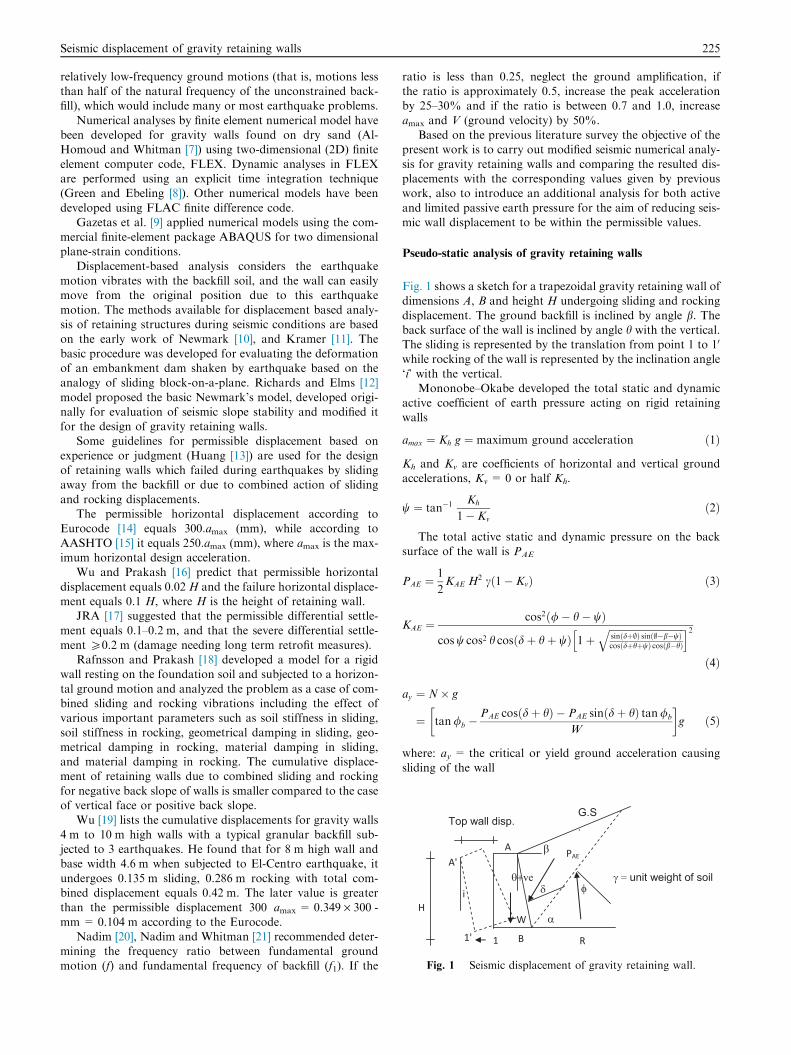
Fig. 1 Seismic displacement of gravity retaining wall.
Seismic displacement of gravity retaining walls 225
relatively low-frequency ground motions (that is, motions lessthan half of the natural frequency of the unconstrained back-fill), which would include many or most earthquake problems.
Numerical analyses by finite element numerical model havebeen developed for gravity walls found on dry sand (Al-Homoud and Whitman [7]) using two-dimensional (2D) finite
element computer code, FLEX. Dynamic analyses in FLEXare performed using an explicit time integration technique(Green and Ebeling [8]). Other numerical models have been
developed using FLAC finite difference code.Gazetas et al. [9] applied numerical models using the com-
mercial finite-element package ABAQUS for two dimensionalplane-strain conditions.
Displacement-based analysis considers the earthquakemotion vibrates with the backfill soil, and the wall can easilymove from the original position due to this earthquake
motion. The methods available for displacement based analy-sis of retaining structures during seismic conditions are basedon the early work of Newmark [10], and Kramer [11]. The
basic procedure was developed for evaluating the deformationof an embankment dam shaken by earthquake based on theanalogy of sliding block-on-a-plane. Richards and Elms [12]
model proposed the basic Newmark’s model, developed origi-nally for evaluation of seismic slope stability and modified itfor the design of gravity retaining walls.
Some guidelines for permissible displacement based on
experience or judgment (Huang [13]) are used for the designof retaining walls which failed during earthquakes by slidingaway from the backfill or due to combined action of sliding
and rocking displacements.The permissible horizontal displacement according to
Eurocode [14] equals 300.amax (mm), while according to
AASHTO [15] it equals 250.amax (mm), where amax is the max-imum horizontal design acceleration.
Wu and Prakash [16] predict that permissible horizontal
displacement equals 0.02 H and the failure horizontal displace-ment equals 0.1 H, where H is the height of retaining wall.
JRA [17] suggested that the permissible differential settle-ment equals 0.1–0.2 m, and that the severe differential settle-
ment P0.2 m (damage needing long term retrofit measures).Rafnsson and Prakash [18] developed a model for a rigid
wall resting on the foundation soil and subjected to a horizon-
tal ground motion and analyzed the problem as a case of com-bined sliding and rocking vibrations including the effect ofvarious important parameters such as soil stiffness in sliding,
soil stiffness in rocking, geometrical damping in sliding, geo-metrical damping in rocking, material damping in sliding,and material damping in rocking. The cumulative displace-ment of retaining walls due to combined sliding and rocking
for negative back slope of walls is smaller compared to the caseof vertical face or positive back slope.
Wu [19] lists the cumulative displacements for gravity walls
4 m to 10 m high walls with a typical granular backfill sub-jected to 3 earthquakes. He found that for 8 m high wall andbase width 4.6 m when subjected to El-Centro earthquake, it
undergoes 0.135 m sliding, 0.286 m rocking with total com-bined displacement equals 0.42 m. The later value is greaterthan the permissible displacement 300 amax = 0.349 · 300 -
mm = 0.104 m according to the Eurocode.Nadim [20], Nadim and Whitman [21] recommended deter-
mining the frequency ratio between fundamental groundmotion (f) and fundamental frequency of backfill (f1). If the
ratio is less than 0.25, neglect the ground amplification, ifthe ratio is approximately 0.5, increase the peak accelerationby 25–30% and if the ratio is between 0.7 and 1.0, increase
amax and V (ground velocity) by 50%.Based on the previous literature survey the objective of the
present work is to carry out modified seismic numerical analy-
sis for gravity retaining walls and comparing the resulted dis-placements with the corresponding values given by previouswork, also to introduce an additional analysis for both active
and limited passive earth pressure for the aim of reducing seis-mic wall displacement to be within the permissible values.
Pseudo-static analysis of gravity retaining walls
Fig. 1 shows a sketch for a trapezoidal gravity retaining wall ofdimensions A, B and height H undergoing sliding and rocking
displacement. The ground backfill is inclined by angle b. Theback surface of the wall is inclined by angle h with the vertical.The sliding is represented by the translation from point 1 to 10
while rocking of the wall is represented by the inclination angle
‘i’ with the vertical.Mononobe–Okabe developed the total static and dynamic
active coefficient of earth pressure acting on rigid retaining
walls
amax ¼ Kh g ¼ maximum ground acceleration ð1Þ
Kh and Kv are coefficients of horizontal and vertical groundaccelerations, Kv = 0 or half Kh.
w ¼ tan�1Kh
1� Kv
ð2Þ
The total active static and dynamic pressure on the backsurface of the wall is PAE
PAE ¼1
2KAE H2 cð1� KvÞ ð3Þ
KAE ¼cos2ð/� h� wÞ
cosw cos2 h cosðdþ hþ wÞ 1þffiffiffiffiffiffiffiffiffiffiffiffiffiffiffiffiffiffiffiffiffiffiffiffiffiffiffiffiffiffisinðdþ;Þ sinð;�b�wÞcosðdþhþwÞ cosðb�hÞ
qh i2ð4Þ
ay ¼ N� g
¼ tan/b �PAE cosðdþ hÞ � PAE sinðdþ hÞ tan/b
W
� �g ð5Þ
where: ay = the critical or yield ground acceleration causingsliding of the wall
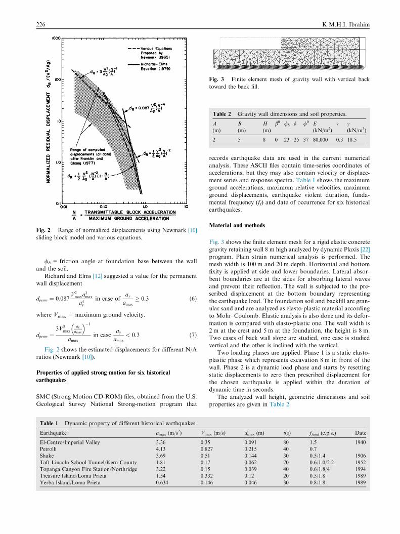
Fig. 2 Range of normalized displacements using Newmark [10]
sliding block model and various equations.
Fig. 3 Finite element mesh of gravity wall with vertical back
toward the back fill.
Table 2 Gravity wall dimensions and soil properties.
A
(m)
B
(m)
H
(m)
b0 /b d /0 E
(kN/m2)
m c(kN/m3)
2 5 8 0 23 25 37 80,000 0.3 18.5
226 K.M.H.I. Ibrahim
/b = friction angle at foundation base between the wall
and the soil.Richard and Elms [12] suggested a value for the permanent
wall displacement
dperm ¼ 0:087V2
maxa3max
a4yin case of
ayamax
� 0:3 ð6Þ
where Vmax = maximum ground velocity.
dperm ¼3V2
maxay
amax
� ��1amax
in caseayamax
< 0:3 ð7Þ
Fig. 2 shows the estimated displacements for different N/A
ratios (Newmark [10]).
Properties of applied strong motion for six historical
earthquakes
SMC (Strong Motion CD-ROM) files, obtained from the U.S.Geological Survey National Strong-motion program that
Table 1 Dynamic property of different historical earthquakes.
Earthquake amax (m/s2) Vm
El-Centro/Imperial Valley 3.36 0.3
Petrolli 4.13 0.8
Shake 3.69 0.5
Taft Lincoln School Tunnel/Kern County 1.81 0.1
Topanga Canyon Fire Station/Northridge 3.22 0.1
Treasure Island/Loma Prieta 1.54 0.3
Yerba Island/Loma Prieta 0.634 0.1
records earthquake data are used in the current numericalanalysis. These ASCII files contain time-series coordinates of
accelerations, but they may also contain velocity or displace-ment series and response spectra. Table 1 shows the maximumground accelerations, maximum relative velocities, maximum
ground displacements, earthquake violent duration, funda-mental frequency (ff) and date of occurrence for six historicalearthquakes.
Material and methods
Fig. 3 shows the finite element mesh for a rigid elastic concrete
gravity retaining wall 8 m high analyzed by dynamic Plaxis [22]program. Plain strain numerical analysis is performed. Themesh width is 100 m and 20 m depth. Horizontal and bottomfixity is applied at side and lower boundaries. Lateral absor-
bent boundaries are at the sides for absorbing lateral wavesand prevent their reflection. The wall is subjected to the pre-scribed displacement at the bottom boundary representing
the earthquake load. The foundation soil and backfill are gran-ular sand and are analyzed as elasto-plastic material accordingto Mohr–Coulomb. Elastic analysis is also done and its defor-
mation is compared with elasto-plastic one. The wall width is2 m at the crest and 5 m at the foundation, the height is 8 m.Two cases of back wall slope are studied, one case is studied
vertical and the other is inclined with the vertical.Two loading phases are applied. Phase 1 is a static elasto-
plastic phase which represents excavation 8 m in front of thewall. Phase 2 is a dynamic load phase and starts by resetting
static displacements to zero then prescribed displacement forthe chosen earthquake is applied within the duration ofdynamic time in seconds.
The analyzed wall height, geometric dimensions and soilproperties are given in Table 2.
ax (m/s) dmax (m) t(s) ffund (c.p.s.) Date
5 0.091 80 1.5 1940
27 0.215 40 0.7
1 0.144 30 0.5/1.4 1906
7 0.062 70 0.6/1.0/2.2 1952
5 0.039 40 0.6/1.8/4 1994
32 0.12 20 0.5/1.8 1989
46 0.046 30 0.8/1.8 1989
0
0.04
0.08
0.12
0.16
0.2
0.24
0.28
0.32
El-centro Petrolli Shake Taft Topanga Trasure Yerba
Numerical wall sliding
Richard and Elms 12
permissible disp. AASHTO 15
Seis
mic
wal
l dis
plac
emen
t (m
)
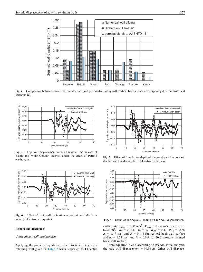
Fig. 4 Comparison between numerical, pseudo-static and permissible sliding with vertical back surface acted upon by different historical
earthquakes.
-0.40
-0.30
-0.20
-0.10
0.00
0.10
0.20
0.30
0 10 20 30 40 50
Mohr-Column analysisElastic analysis
Top
wal
l sei
smic
dis
plac
emen
t (m
)
Dynamic time (s)
Fig. 5 Top wall displacement versus dynamic time in case of
elastic and Mohr–Column analysis under the effect of Petrolli
earthquake.
-0.15
-0.10
-0.05
0.00
0.05
0.10
0.15
0 10 20 30 40 50 60 70
Inclined back wallVertical back wall
Sei
smic
top
wal
l dis
plac
emen
t (m
)
Dynamic time (s)
Fig. 6 Effect of back wall inclination on seismic wall displace-
ment (El-Centro earthquake).
-0.15
-0.10
-0.05
0.00
0.05
0.10
0.15
0 10 20 30 40 50 60 70
Zero foundation depth2 m foundation depth
Dynamic time (s)
Top
seis
mic
wal
l dis
plac
emen
t (m
)
Fig. 7 Effect of foundation depth of the gravity wall on seismic
displacement under applied El-Centro earthquake.
-0.35
-0.30
-0.25
-0.20
-0.15
-0.10-0.05
0.00
0.05
0.10
0.15
0 10 20 30 40 50 60 70
Taft EQ.Petrolia EQ.
Top
wal
l dis
plac
emen
t (m
)
Dynamic time (s)
Fig. 8 Effect of earthquake loading on top wall displacement.
Seismic displacement of gravity retaining walls 227
Results and discussions
Conventional wall displacement
Applying the previous equations from 1 to 6 on the gravityretaining wall given in Table 2 when subjected to El-centro
earthquake amax = 3.36 m/s2, Vmax = 0.352 m/s, then W =
67.2 t/m1, Kh = 0.144, Kv = 0, KAE = 0.4, PAE = 25.9,ay = 1.47 m/s2 and N = 0.144 for vertical back wall surfaceand ay = 1.68 m/s2 and N= 0.168 for 20.6� positive inclinedback wall surface.
From equation 6 and according to pseudo-static analysis,the base wall displacement = 10.13 cm. Other wall displace-
-0.15
-0.10
-0.05
0.00
0.05
0.10
0.15
0 10 20 30 40 50 60 70
Top wall disp.
Foundation wall disp.
Wal
l sei
smic
dis
plac
emen
t (m
)
Dynamic time (s)
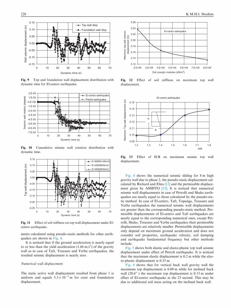
Fig. 9 Top and foundation wall displacement distribution with
dynamic time for El-centro earthquake.
0.12
0.14
0.16
0.18
0.20
0.22
0.24
0.26
2.E+04 3.E+04 4.E+04 5.E+04 6.E+04 7.E+04 8.E+04
Max
imum
top
wal
l sei
smic
di
spla
cem
ent (
m)
Soil young's modulus (kN/m2)
El-centro eathquake
Fig. 12 Effect of soil stiffness on maximum top wall
displacement.
-7.E-03-6.E-03
-5.E-03-4.E-03
-3.E-03-2.E-03
-1.E-030.E+00
1.E-032.E-03
0 10 20 30 40 50 60 70
El-centro earthquakePetroli earthquake
Sei
smic
wal
l rot
atio
n (d
egre
e)
Dynamic time (s)
Fig. 10 Cumulative seismic wall rotation distribution with
dynamic time.
-0.25
-0.20
-0.15
-0.10
-0.05
0.00
0.05
0.10
0.15
0 10 20 30 40 50 60 70
E=80000 kN/m2E=20000kN/m2E=40000kN/m2
Top
wal
l dis
plac
emen
t (m
)
Dynamic time (s)
Fig. 11 Effect of soil stiffness on top wall displacement under El-
centro earthquake.
El-centro earthquake
0.09
0.10
0.11
0.12
0.13
0.14
0.15
1.2 1.3 1.4 1.5 1.6 1.7 1.8H/B
Max
imum
Top
wal
l dis
plac
emen
t (m
)
B
H
Fig. 13 Effect of H/B on maximum seismic top wall
displacement.
228 K.M.H.I. Ibrahim
ments calculated using pseudo-static methods for other earth-quakes are shown in Fig. 4.
It is noticed that if the ground acceleration is nearly equalto or less than the yield acceleration (1.68 m/s2) of the gravitywall as in case of Taft, Treasure and Yerba earthquakes, the
resulted seismic displacement is nearly zero.
Numerical wall displacement
The static active wall displacement resulted from phase 1 isuniform and equals 5.3 · 10�3 m for crest and foundationdisplacement.
Fig. 4 shows the numerical seismic sliding for 8 m highgravity wall due to phase 2, the pseudo-static displacement cal-culated by Richard and Elms [12] and the permissible displace-
ment given by ASSHTO [15]. It is noticed that numericalseismic wall displacements in case of Petrolli and Shake earth-quakes are nearly equal to those calculated by the pseudo-sta-
tic method. In case of El-centro, Taft, Topanga, Treasure andYerba earthquakes the numerical seismic wall displacementsare greater than the corresponding pseudo-static method. Per-
missible displacements of El-centro and Taft earthquakes arenearly equal to the corresponding numerical ones, except Pet-rolli, Shake, Treasure and Yerba earthquakes their permissibledisplacements are relatively smaller. Permissible displacements
only depend on maximum ground acceleration and does notconsider soil properties, earthquake velocity, soil dampingand earthquake fundamental frequency but other methods
include.Fig. 5 shows both elastic and elasto-plastic top wall seismic
displacement under effect of Petroli earthquake. It is noticed
that the maximum elastic displacement is 0.2 m while the elas-to-plastic displacement is 0.33 m.
Fig. 6 shows that for vertical back wall gravity wall the
maximum top displacement is 0.09 m while for inclined backwall (20.6o ) the maximum top displacement is 0.13 m undereffect of El-centro earthquake at the 23 second. This may bedue to additional soil mass acting on the inclined back wall.
Seismic displacement of gravity retaining walls 229
Fig. 7 show that 2 m foundation depth reduces the maxi-mum top displacement from 0.133 m to 0.09 m under effectof El-Centro earthquake. Passive resistance reduces the seismic
wall displacement.Fig. 8 shows the top wall displacement distribution under
effect of Taft and Petrolia earthquake for inclined positive
back slope gravity wall. The maximum ground accelerationsare 1.81 and 4.13 m/s2 while the corresponding maximumtop wall displacements are -0.076 and 0.33 m at 55.6 s and
26.7 s respectively. It is noticed that Taft earthquake totalduration is 66 s and causes residual plastic top wall displace-ment about -0.03 m while in case of Petroli earthquake theresidual plastic end displacement is about -0.19 m. The final
permanent seismic wall displacement is directly proportionalto the maximum ground acceleration.
Fig. 9 shows the top and foundation wall displacement dis-
tribution with dynamic time for El-centro earthquake. Themaximum top wall displacement is 0.133 m occurs at 23.75 sec-onds while the corresponding foundation displacement is
0.095 m. The difference between both displacements dividedby the wall height represents the wall seismic rotation angleas shown in Fig. 10.
Fig. 10 shows the cumulative seismic wall rotation for bothEl-centro and Petroli earthquakes. The seismic wall rotationincreases gradually with dynamic time and reaches its peakvalue at end of the earthquake.
Fig. 11 shows the seismic top wall displacement withdynamic time for three granular soils with young’s modulus20000, 40000 and 80000 kN/m2. It is noticed that the seismic
wall displacement decreases as soil young’s modulus increase.Fig. 12, shows that the maximum corresponding seismic
top wall displacements are 0.236, 0.166 and 0.133 m
respectively.Fig. 13 shows the effect of increasing wall height with
respect to footing breadth. The maximum top wall displace-
ment increases with increasing the wall height. For H/b lessthan 1.4 the wall behaves as a rigid body and sliding is domi-nant while rotation is nearly zero. For H/B greater than 1.4and less than 1.6 the wall becomes more flexible and wall rota-
tion increases. For H/B equals 1.8 represents the maximumwall seismic displacement and beyond that it is noticed thatoverturning failure takes place.
Conclusion
- Some numerical seismic displacements for studied historicalground motions are nearly equal to those calculated by the
pseudo-static method and others are relatively greater.- Permissible seismic wall displacement calculated byAASHTO [15] can be used for empirical displacement esti-
mation as it depends only on maximum ground accelera-tion and does not consider the effect of soil stiffness,earthquake fundamental frequency and dynamic time.
- Gravity retaining walls with inclined positive back slopesurface undergoes greater total sliding and rocking dis-placements than vertical back walls due to increase in massand inertia horizontal force of backfill.
- The cumulative seismic wall rotation increases graduallywith dynamic time and reaches maximum at the end ofearthquake.
- Increase in soil flexibility increases too much the seismicwall displacement.
- In the study, for rigid gravity walls having H/B less than 1.4
seismic sliding is dominant while wall rotation is nearlyzero. For greater ratios, the wall becomes more flexibleand its rotation increases till overturning and failure takes
place.
Conflict of interest
None declared.
References
[1] N. Mononobe, H. Matuo, On the determination of earth
pressures during earthquakes, Proc. World Engrg. Congr.,
Tokyo, Japan 1929, 9, paper (388).
[2] S. Okabe, General theory of earth pressure and seismic stability
of retaining wall and dam, J. Japan Soc. Civ. Engrs., Tokyo,
Japan 1924, 12(1).
[3] D. Choudhury, K.S. Subba Rao, S. Ghosh, Passive earth pressure
distribution under seismic condition, 15th Eng. Mechanics
Conference of ASCE, Columbia University, New York, 2002.
[4] P. Ortigosa, Seismic earth pressure including soil cohesion, the
16th International Conference on Soil Mechanics and
Geotechnical Engineering, Osaka, 2005.
[5] R.S. Steedman, X. Zeng, The influence of phase on the
calculation of pseudo-static earth pressure on a retaining wall,
Geotechnique 40 (1) (1990) 103–112.
[6] A.S. Veletsos, A.H. Younan, Dynamic modelling and response
of soil-wall systems, J. Geotech. Engrg. ASCE 120 (12) (1994B)
2155–2179.
[7] A.S. Al-Homoud, R.V. Whitman, Seismic analysis and design of
rigidbridge abutment considering rotationand sliding incorporating
non-linear soil behaviour, Soil Dynam. Eng. (1999) 247–277.
[8] R.A. Green, R.M. Ebeling, Modelling the dynamic response of
cantilever earth-retaining walls using FLAC, Numeric. Model.
Geomech. (2003).
[9] G. Gazetas, P. Psarropoulos, I. Anastasopoulos, N. Gerolymos,
Seismic behaviour of flexible retaining systems subjected to short
duration moderately-strong excitation, Soil Dynam. Earthqu.
Eng. 25 (2005) 537–550.
[10] N.N. Newmark, Effect of earthquakes on dams and
embankments, Geotechnique 15 (2) (1965) 139–160.
[11] S.L. Kramer, Geotechnical Earthquake Engineering, Prentice-
Hall, New Jersey, 1996, pp. 466–505.
[12] R. Richard, D.G. Elms, Seismic behaviour of gravity retaining
walls, J. Geotec. Engrg. ASCE (1979) 105 (GT4).
[13] Chin-Chan Huang, Seismic displacement of soil retaining walls
situated on slope, J. Geotechn. Geo-Environ. Eng. ASCE 31 (9)
(2005) 1108–1117.
[14] EUROCODE 8 (European pre-standard), Design Provisions for
Earthquake Resistance of Structures-Part 5: Foundations
Retaining Structures and Geotechnical Aspects, The
Commission of the European Communities, 1994.
[15] American Association of State Highway and Transportation
Officials, Standard Specifications for Highway Bridges,
(AASHTO) Sections 3 and 7, 2002.
[16] Y.Wu, S. Prakash, Effect of submergence on seismic displacement
of rigid walls, Earthquake Geotechnical Engineering, 1999
Balkema, Rotterdam, ISBN 90 5809 1163, 1999.
[17] JRA, Seismic Design Specifications and Construction of
highway Bridges, Japan Road Association, 1996.
[18] E.A. Rafnsson, S. Prakash, Stiffness and damping parameters
for dynamic analysis of retaining walls, in: Proc. Of 2nd
International Conference on Recent Advances in Geotechnical
Earthquake Eng. and Soil Dynamics, St. Louis MO, 1991, vol.
3, pp. 1943–2952.

230 K.M.H.I. Ibrahim
[19] Y. Wu, Displacement-based analysis and design of rigid
retaining walls to real earthquakes, PhD. Dissertation, Uni of
Missouri-Rolla, 1999.
[20] F. Nadim, A numerical model for evaluation of seismic
behaviour of gravity retaining walls, ScD Thesis, Department
of Civil Eng., M.I.T., Cambridge, MA, 1982.
[21] F. Nadim, R.V. Whitman, Coupled sliding and tilting of gravity
retaining walls, J. Geot. Eng. Divis. ASDCE 109 (7) (1983) 915–
931.
[22] Plaxis 2D – Version 8, R.B.J. Brinkgreve (Ed.), Delft University
of Technology & Plaxis b.v., Netherland, P.O. Box 572, 2600
AN DELFT, Netherlands.