Embed Size (px)
Citation preview
Yucca Mountain Site Characterization Project
TOPICAL REPORT YMPITR-003-NP
SEISMIC DESIGN METHODOLOGY FOR A
GEOLOGIC REPOSITORY AT YUCCA MOUNTAIN
October 1995
U.S. Department of Energy Office of Civilian Radioactive Waste Management
Las Vegas, NV 89109
9511030318 951031 PDR WASTE WM-11 PDR
Topical Report YMP/TR-003-NP Seismic Design Methodology fora Geologic Repository at Yucca Mountain
Approved by:Date
Yuca ountain Site Charact rization Project
kchard E. Spence irector Yucca Mountain Quality Assurance Division
Topical Report YMP/TR-003-NP Seismic Design Methodology for a Geologic Repository at Yucca Mountain
ABSTRACT
This topical report describes the design methodology and criteria that the U.S. Department of Energy (DOE) proposes to use to accommodate vibratory ground motion and fault displacement hazards during preclosure at a geologic repository at Yucca Mountain. This is the second of three topical reports that together describe the seismic design process for Yucca Mountain. A previous topical report, YMP/TR-002-NP, Methodology to Assess Fault Displacement and Vibratory Ground Motion Hazards at Yucca Mountain, described the probabilisLic seismic hazard assessment methodology that the DOE proposes to use for Yucca Mountain. A third topical report will describe the results of probabilistic seismic hazard assessments, and how those results will be used, together with other information, to determine design basis ground motions and fault displacements that are consistent with the design methodology described in this topical report.
The seismic design methodology and criteria are based on the DOE's safety performance goal-based seismic design methodology. Safety performance categories have been specifically established for Yucca Mountain structures, systems, and components based on functional performance requirements and public safety consequences of failure. This graded approach establishes safety performance goals for each of the four performance categories. For the highest safety performance category, the numerical performance goal is consistent with the safety performance of nuclear power reactors, as determined from probabilistic risk assessments. For structures, systems, and components with no radiological safety significance, the numerical safety performance goals are consistent with established building codes for non-critical facilities.
This report describes the seismic design methodology that will be applied for underground openings and ground support systems. No precedents are available for the design of extensive underground facilities in accordance with Nuclear Regulatory Commission (NRC) regulatory requirements. The DOE performance goal-based seismic design methodology was developed mainly for design of surface facilities. Its application to underground facilities, as developed in this report, represents an extension of previous applications of the methodology. This report provides an approach that will achieve the required level of seismic design conservatism for each underground facility performance category. The approach is consistent with applicable regulatory requirements and is implementable at an underground facility of this type.
The report describes the DOE design approach for expected fault displacements. Consistent with the NRC Staff Technical Position on Consideration of Fault Displacement Hazards in Geologic Repository Design, NUREG-1494, the requirement will be fault avoidance to the extent achievable. Required fault set-back distance will be addressed on a case-by-case basis. Where fault avoidance is not practical or reasonable, engineering criteria or repair and rehabilitation actions will be taken to ensure that preclosure safety performance objectives are met.
October 1995Uli

Topical Report YMP/TR-003-NP Seismic Design Methodology for a Geologic Repository at Yucca Mountain
INTENTIONALLY LEFT BLANK
October 1995 iv.
Topical Report YMPITR-003-NP
Seismic Design Methodology for a Geologic Repository at Yucca Mountain
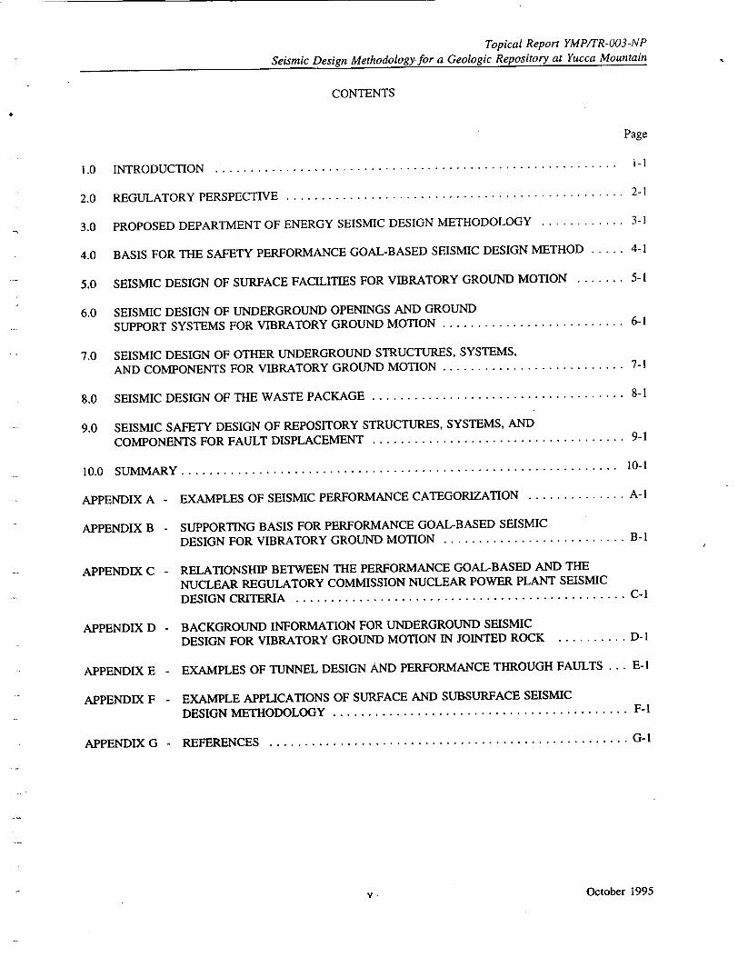
CONTENTS
Page
1.0 INTRODUCTION .. ......................................................... i-1
2.0 REGULATORY PERSPECTIVE ................................................ 2-1
3.0 PROPOSED DEPARTMENT OF ENERGY SEISMIC DESIGN METHODOLOGY ............ 3-1
4.0 BASIS FOR THE SAFETY PERFORMANCE GOAL-BASED SEISMIC DESIGN METHOD ..... 4-1
5.0 SEISMIC DESIGN OF SURFACE FACILITIES FOR VIBRATORY GROUND MOTION ....... 5-1
6.0 SEISMIC DESIGN OF UNDERGROUND OPENINGS AND GROUND
SUPPORT SYSTEMS FOR VIBRATORY GROUND MOTION .......................... 6-1
7.0 SEISMIC DESIGN OF OTHER UNDERGROUND STRUCTURES, SYSTEMS,
AND COMPONENTS FOR VIBRATORY GROUND MOTION .......................... 7-1
8.0 SEISMIC DESIGN OF THE WASTE PACKAGE .................................... 8-1
9.0 SEISMIC SAFETY DESIGN OF REPOSITORY STRUCTURES, SYSTEMS, AND
COMPONENTS FOR FAULT DISPLACEMENT .................................... 9-1
10.0 SUM M ARY ............................................................... 10-1
APPENDIX A - EXAMPLES OF SEISMIC PERFORMANCE CATEGORIZATION .............. A-I
APPENDIX B - SUPPORTING BASIS FOR PERFORMANCE GOAL-BASED SEISMIC
DESIGN FOR VIBRATORY GROUND MOTION .......................... B-1
APPENDIX C - RELATIONSHIP BETWEEN THE PERFORMANCE GOAL-BASED AND THE
NUCLEAR REGULATORY COMMISSION NUCLEAR POWER PLANT SEISMIC DESIGN CRITERIA ............................................... C-I
APPENDIX D - BACKGROUND INFORMATION FOR UNDERGROUND SEISMIC
DESIGN FOR VIBRATORY GROUND MOTION IN JOINTED ROCK .......... D-1
APPENDIX E - EXAMPLES OF TUNNEL DESIGN AND PERFORMANCE THROUGH FAULTS ... E-I
"APPENDIX F - EXAMPLE APPLICATIONS OF SURFACE AND SUBSURFACE SEISMIC
DESIGN METHODOLOGY .......................................... F-I
APPENDIX G - REFERENCES ................................................... G-I
v- October 1995
Topical Report YMP/TR-003-NP Seismic Design Methodology for a Geologic Repository at Yucca Mountain
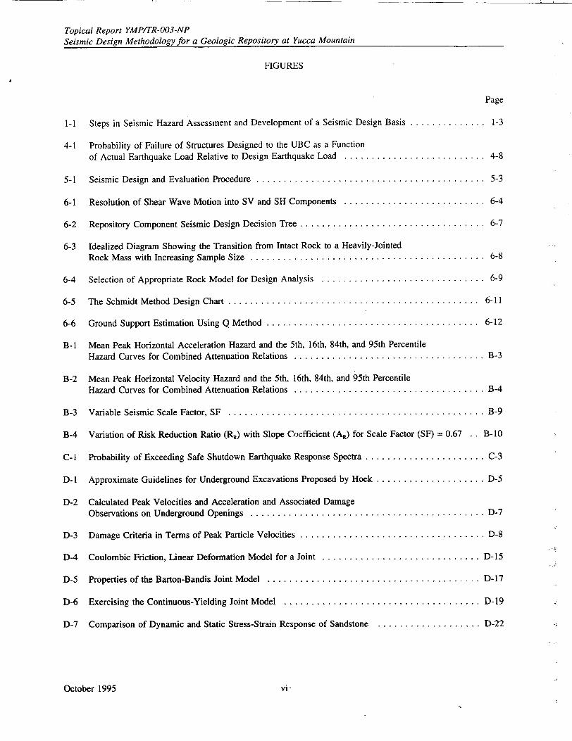
FIGURES
Page
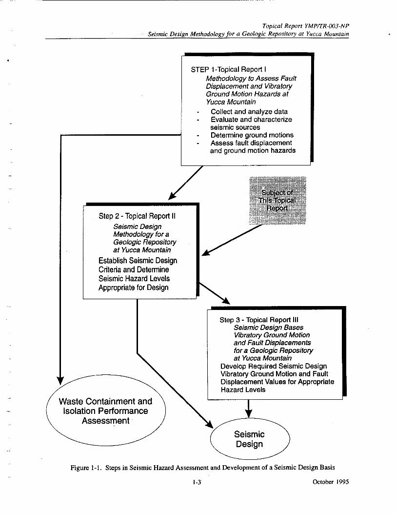
1-1 Steps in Seismic Hazard Assessment and Development of a Seismic Design Basis .............. 1-3
4-1 Probability of Failure of Structures Designed to the UBC as a Function of Actual Earthquake Load Relative to Design Earthquake Load .......................... 4-8
5-1 Seismic Design and Evaluation Procedure ........................................... 5-3
6-1 Resolution of Shear Wave Motion into SV and SH Components .......................... 6-4
6-2 Repository Component Seismic Design Decision Tree .................................. 6-7
6-3 Idealized Diagram Showing the Transition from Intact Rock to a Heavily-Jointed Rock Mass with Increasing Sample Size ............................................ 6-8
6-4 Selection of Appropriate Rock Model for Design Analysis .............................. 6-9
6-5 The Schmidt Method Design Chart ............................................... 6-11
6-6 Ground Support Estimation Using Q Method ........................................ 6-12
B-1 Mean Peak Horizontal Acceleration Hazard and the 5th, 16th, 84th, and 95th Percentile Hazard Curves for Combined Attenuation Relations ................................... B-3
B-2 Mean Peak Horizontal Velocity Hazard and the 5th, 16th, 84th, and 95th Percentile Hazard Curves for Combined Attenuation Relations ................................... B-4
B-3 Variable Seismic Scale Factor, SF ............................................... B-9
B-4 Variation of Risk Reduction Ratio (RR) with Slope Coefficient (AR) for Scale Factor (SF) = 0.67 . . B-10
C-1 Probability of Exceeding Safe Shutdown Earthquake Response Spectra ...................... C-3
D-I Approximate Guidelines for Underground Excavations Proposed by Hoek .................... D-5
D-2 Calculated Peak Velocities and Acceleration and Associated Damage Observations on Underground Openings ........................................... D-7
D-3 Damage Criteria in Terms of Peak Particle Velocities .................................. D-8
D-4 Coulombic Friction, Linear Deformation Model for a Joint ............................. D- 15
D-5 Properties of the Barton-Bandis Joint Model ....................................... D-17
D-6 Exercising the Continuous-Yielding Joint Model .................................... D- 19
D-7 Comparison of Dynamic and Static Stress-Strain Response of Sandstone ................... D-22
October 1995 vi
Topical Report YMPITR-003-NP Seismic Design Methodology for a Geologic Repository at Yucca Mountain
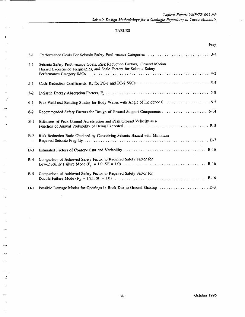
TABLES
Page
3-1 Performance Goals For Seismic Safety Performance Categories .......................... 3-4
4-1 Seismic Safety Performance Goals, Risk Reduction Factors, Ground Motion Hazard Exceedance Frequencies, and Scale Factors for Seismic Safety Performance Category SSCs .................................................... 4-2
5-1 Code Reduction Coefficients, R, for PC-I and PC-2 SSCs .............................. 5-5
5-2 Inelastic Energy Absorption Factors, F,.............................................. 5-8
6-1 Free-Field and Bending Strains for Body Waves with Angle of Incidence 0 .................. 6-5
6-2 Recommended Safety Factors for Design of Ground Support Components ................... 6-14
B-1 Estimates of Peak Ground Acceleration and Peak Ground Velocity as a Function of Annual Probability of Being Exceeded .................................... B-5
B-2 Risk Reduction Ratio Obtained by Convolving Seismic Hazard with Minimum Required Seismic Fragility ...................................................... B-7
B-3 Estimated Factors of Conservatism and Variability ................................... B-16
B-4 Comparison of Achieved Safety Factor to Required Safety Factor for Low-Ductility Failure Mode (F. = 1.0; SF = 1.0) ................................... B-16
B-5 Comparison of Achieved Safety Factor to Required Safety Factor for Ductile Failure Mode (F. = 1.75; SF = 1.0) ....................................... B-16
D-1 Possible Damage Modes for Openings in Rock Due to Ground Shaking ..................... D-3
October 1995vii.
Topical Report YMP/TR-003-NP Seismic Design Methodology for a Geologic Repository at Yucca Mountain
ACRONYMS
ACI American Concrete Institute
AISC American Institute of Steel Construction
ASCE American Society of Civil Engineers
ASLB Atomic Safety and Licensing Board
ATC Applied Technology Council
BNL Brookhaven National Laboratory
CFR Code of Federal Regulations
DBE Design basis earthquake
DBH Design basis seismic hazard
DOE U.S. Department of Energy
EPRI Electric Power Research Institute
FR Federal Register
GETR General Electric Company Test Reactor
GROA Geologic Repository Operations Area
HLW High-level waste
IEEE Institute of Electrical and Electronic Engineers
IMPF Intermediate moment (resisting/resting) frame
IRS In-structure response spectrum
NRC U.S. Nuclear Regulatory Commission
PC Performance Category
PGA Peak ground acceleration
PGV Peak ground velocity
PGSD Performance goal-based seismic design
PRA Probabilistic risk assessment
RQD Rock Quality Designation
RRS Required response spectrum
SDBH Scaled design basis hazard
SF Scale factor
SH Shear horizontal
SMRF Special moment resisting frame
SPGV SDBH peak ground velocity
SSC Systems, structures, and components
STP (NRC) Staff Technical Position
SV Shear vertical
UBC Uniform Building Code
UCRL University of California Research Laboratory
UOGSS Underground Openings and Ground Support Systems
October 1995 viii
Topical Report YMPITR-003-NP
Seismic Design Methodology for a Geologic Repository at Yucca Mountain
1.0 INTRODUCTION
This topical report describes the methodology and criteria that the U.S. Department of Energy (DOE)
proposes to use for preclosure seismic design of the proposed Geologic Repository Operations Area
(GROA) structures, systems, and components (SSCs) for vibratory ground motion and fault
displacement. As discussed in Section 2.0 of this report, Title 10 of the Code of Federal Regulations,
Part 60 (10 CFR Part 60), specifically Section 60.41(c), states that for a license to be issued for the
proposed Yucca Mountain high-level waste repository, the Nuclear Regulatory Commission (NRC) must
find that the facility will not constitute an unreasonable risk to the health and safety of the public. The
regulation requires that such a decision be based on the standard of reasonable assurance, recognizing
that uncertainties exist in technology and knowledge of the natural environment and taking account of
these uncertainties in the decision process. The standard of reasonable assurance for safety decision
making is particularly emphasized in Section 60.101(a), which describes the purpose and nature of the
safety findings. Section 60.131(b)(1) requires that SSCs important to safety shall be designed so that
natural phenomena and environmental conditions anticipated at the GROA will not interfere with
necessary safety functions.
Among the natural phenomena specifically identified in the regulation as requiring safety consideration
are the hazards of ground shaking and fault displacement due to earthquakes. Sections 60.21(c)(2) and
(-3) describe the required content of the license application. These sections of the regulation require that
the DOE describe 1) the principal design criteria and their relation to the performance objectives set
forth in Section 60.111, 2) the codes and standards that the DOE proposes to use to demonstrate
compliance with the design criteria, and 3) the analysis and performance requirements for SSCs that are
important to safety. In preparing this topical report and submitting it to the NRC for early review, the
DOE intends to respond to the license application requirements of Sections 60.21(c)(2) and (3) with
respect to preclosure seismic safety and to describe the seismic safety performance goals that it proposes
to meet for the facility SSCs to provide reasonable assurance of complying with the preclosure radiation
health and safety performance objectives contained in Section 60.111.
As discussed in Section 2.0 of this report, 10 CFR Part 60 does not provide specific guidance on how to
determine the design basis vibratory ground motion and fault displacement values appropriate for design
of the facility. Also, the regulation does not provide guidance for the appropriate design methodology
that should be implemented or the technical criteria that should be satisfied to meet regulatory
requirements. Thus, this topical report describes the technical approaches that the DOE intends to use to
meet the preclosure radiation safety requirements of the regulation with respect to vibratory ground motion and fault displacement.
1.1 BACKGROUND
The DOE presented an approach for assessing seismic hazards' and accomplishing seismic design of the
proposed Yucca Mountain GROA in its Site Characterization Plan (DOE 1988, Section 8). In its review
of that proposed approach, the NRC staff identified a number of items that they felt required additional
development and clarification (NRC, 1989b). Subsequent to the publication of the Site Characterization
Plan several important developments relevant to the seismic hazard evaluation and seismic design of the
proposed Yucca Mountain GROA have occurred. Consequently, the DOE has revised its seismic design
process as described in the first of three topical reports (DOE, 1994a) to incorporate these developments.
The phrase "seismic hazard" in its broadest definition is any physical phenomenon (e.g., ground shaking,
ground failure) associated with an earthquake that may produce adverse effects on human activities. This report uses the phrase to mean either vibratory ground motion or fault displacement.
October 19951-1-
Topical Report YMP/TR-003-NP Seismic Design Methodology for a Geologic Repository at Yucca Mountain
In two other important developments, the NRC staff issued guidance on investigations to identify and evaluate faults that are significant for assessing seismic hazards (NRC, 1992a) and, recently, on consideration of fault displacements for seismic design of a geologic repository (NRC, 1994a).
In addition to this guidance, there have been significant technical and regulatory developments with respect to determining the seismic design basis for nuclear power plants. During the past 10 years, the nuclear utility industry and the NRC have developed comprehensive probabilistic seismic hazard assessment methodologies specifically for evaluating the seismic design bases for nuclear power plants. The industry methodology, which is the basis for the computational code EQHAZARD, was submitted to the NRC in a topical report by the Electric Power Research Institute (EPRI, 1989). The EPRI report was extensively reviewed by the NRC staff and its advisor, the U.S. Geological Survey, and accepted for evaluating the seismic design bases for nuclear power plants. 2 Recently the NRC has initiated revision of its seismic and geologic siting regulation governing power reactor licensing. In the draft revision published for review (59 FR 52255, 60 FR 10880) the NRC has incorporated probabilistic techniques for seismic hazard assessment in an effort to achieve stable design bases for future nuclear power plants. Finally, in parallel with the above, the DOE developed a robust seismic design methodology and procedures for application to a wlde range of non-power generating nuclear facilities. The DOE methodology has come to be called the "performance goal-based" seismic design methodology. The major significance of this methodology is that it provides for explicit design of facility SSCs, according to their importance to safety, and permits the design requirements to be linked to probabilistic seismic hazard results to achieve approximately uniform risk of seismic consequences throughout the facility. These improved methods and procedures have gained broad professional acceptance.
Because of these important developments, the DOE has re-evaluated and revised its approach, presented earlier in the Site Characterization Plan, for seismic design of the proposed Yucca Mountain GROA. The revised approach builds upon the new technological and regulatory developments related to seismic design of nuclear facilities. The three elements of the DOE's seismic design process are summarized in Section 1.2.
1.2 OVERVIEW OF THE GROA PRECLOSURE SEISMIC DESIGN PROCESS
For timely resolution of issues related to seismic design, the DOE developed an integrated seismic design basis evaluation and seismic design process. The process is divided into three closely linked elements which can be separately developed and submitted for NRC review: probabilistic methodology to assess seismic hazards, seismic design methodology and criteria, and determination of vibratory ground motion and fault displacement values appropriate for seismic design of the facility SSCs. The DOE is documenting its proposed seismic design process in three topical reports. Each report describes one of the elements, shown together in their sequential relationship in Figure 1-1. Topical Report I, Methodology to Assess Fault Displacement and Vibratory Ground Motion Hazards at Yucca Mountain (DOE, 1994a), was submitted to the NRC for review in June 1994. Topical Report II (this report) describes DOE's seismic design methodology and criteria for the Yucca Mountain GROA to meet the NRC's preclosure radiological safety requirements. Topical Report III, to be submitted in 1997, will describe DOE's assessment of the seismic hazards for the Yucca Mountain GROA and its determination of vibratory ground motion and fault displacement values appropriate for design of the GROA SSCs.
2 The NRC staff prepared a Safety Evaluation Report accepting the industry's probabilistic seismic hazard
methodology for application (EPRI, 1989).
October 1995 1-2
Topical Report YMP/TR-003-NP
Seismic Design Methodology for a Geologic Repository at Yucca Mountain
Figure 1-1. Steps in Seismic Hazard Assessment and Development of a Seismic Design Basis
October 1995
STEP 1-Topical Report I Methodology to Assess Fault Displacement and Vibratory Ground Motion Hazards at Yucca Mountain
- Collect and analyze data - Evaluate and characterize
seismic sources - Determine ground motions - Assess fault displacement
and ground motion hazards
Step 2 - Topical Report II Seismic Design Methodology for a Geologic Repository at Yucca Mountain
Establish Seismic Design Criteria and Determine Seismic Hazard Levels Appropriate for Design
Step 3 - Topical Report III Seismic Design Bases Vibratory Ground Motion and Fault Displacements for a Geologic Repository at Yucca Mountain
Develop Required Seismic Design Vibratory Ground Motion and Fault
or Appropriatuisplacement values i{ Hazard Levels
!
11111
'k
Waste Containment and Isolation Performance
Assessment
1-3'
Topical Report YMP/TR-003-NP
Seismic Design Methodology for a Geologic Repository at Yucca Mountain
By separately submitting the elements of its proposed seismic design process, the DOE is seeking to
make efficient use of its resources by obtaining the NRC's early feedback and guidance on the
application of its proposed probabilistic seismic hazard assessment methodology (Topical Report I), and
its proposed seismic design criteria and methodology (this report) before proceeding with the hazards
assessment and determination of vibratory ground motion and fault displacement values appropriate for
seismic design of the GROA SSCs. More details of the reports are given in the following paragraphs.
Topical Report I Topical Report I describes the DOE's methodology for probabilistic assessment of
vibratory ground motion and fault displacement hazards. The methodology involves a series of
workshops structured so that multiple experts can interact to evaluate hypotheses and models using the
Yucca Mountain site and area geological, geophysical, and seismological data sets. The data sets will
be made available to all participant experts uniformly and at common scales. Importantly, the
methodology requires that the experts specifically evaluate all hypotheses and models that have credible
support in the data. The product of the methodology is multiple interpretations by the experts of
seismic sources, source properties, and evaluations of ground motion, all of which include specific
expressions of uncertainty. The methodology does not involve expert opinion, which implies judgments
unconstrained by data or normal scientific rigor, but instead employs normal earth science procedures
and practice, and carries the usual past practice one step further by requiring uncertainty in the interpretations to be specifically expressed. Moreover, it forces a consistent level of scientific rigor, a
comprehensive and consistent consideration of data, and documentation of interpretations beyond normal
past practice. Additional information on the methodology is contained in Probabilistic Analyses of
Ground Motion and Fault Displacement at Yucca Mountain, Yucca Mountain study plan 8.3.1.17.3.6 (DOE, 1995).
Topical Report I does not provide the values of vibratory ground motion and fault displacement hazards
for design c, the facility SSCs; it describes only the methodology for hazard assessment. The application of this methodology at the Yucca Mountain site will yield hazard results that will, together with deterministic evaluations to be performed as part of the Topical Report III effort, comprise the
information base considered in determining design basis vibratory ground motion and fault displacement
values. The methodology also can be used to develop seismic hazard inputs to the waste containment
and isolation performance assessment.
Topical Report II Topical Report I1 describes the seismic design methodology and criteria that DOE
intends to follow to provide reasonable assurance that vibratory ground motions or fault displacement
will not unduly compromise the safety functions of the Yucca Mountain GROA SSCs. The seismic
design methodology and criteria proposed in this topical report use the DOE's safety performance
goals 3-based seismic design methodology described in Natural Phenomena Hazards Design and
Evaluation Criteria for Department of Energy Facilities (DOE, 1994b). Safety performance categories
have been specifically established for the Yucca Mountain GROA SSCs based on their functional
performance requirements and safety consequences of failure (i.e., safety of workers, the general public,
and the environment), and they take account of mission as well as cost impact.
For the GROA SSCs in the highest safety performance category, the proposed seismic design criteria
and requirements for vibratory ground motion are essentially those used for nuclear plant seismic design
of Category I SSCs (see Section 3 and Appendix C). For SSCs with no radiological safety significance, the seismic design criteria and requirements are founded in established codes and practice contained in
the Uniform Building Code governing the seismic design of non-critical facilities.
The term "safety performance goal" as used in this topical report, refers to the target annual probability
of unacceptable SSC performance that should not be exceeded for a seismic design category. The
seismic design process based on this concept is referred to as "performance goal-based" seismic design
(see Section 3).
October 1995 1-4
Topical Report YMPITR-003-NP
Seismic Design Methodology for a Geologic Repository at Yucca Mountain
Topical Report H also describes the methodology and criteria for design of the Yucca Mountain GROA
SSCs for fault displacement. The methodology and criteria incorporate the NRC Staff Technical
Position on Consideration of Fault Displacement Hazards in Geologic Repository Design, NUREG-1494
(NRC, 1994a). The report describes the criteria for avoiding faults, as well as criteria for fault
displacement design of SSCs when design is the appropriate mitigation action.
Topical Report HI Topical Report III will describe the DOE's determination of vibratory ground motion
and fault displacement inputs appropriate for seismic design of the Yucca Mountain GROA SSCs. The
DOE expects to determine the appropriate inputs using an information base that includes both
probabilistic hazard and deterministic evaluations. The methodology described in Topical Report I will
be implemented to assess the probability of vibratory ground motion and fault displacement for the
Yucca Mountain site. The safety performance requirements for seismic design of the facility SSCs,
described in Topical Report II, will form the basis for determining the seismic hazard levels appropriate
for design. Thus, it is intended that Topical Report III will apply both the methodology described in
Topical Report I and the methodology and criteria described in Topical Report II. In addition, as part
of the preparation of Topical Report III, the DOE intends to perform deterministic evaluations of Type I
faults and candidate Type I faults that lie within 5 km of the Yucca Mountain site, including estimations
of maximum earthquake magnitudes for the faults.
-It is anticipated that seismic design inputs will be determined from controlling earthquakes identified
from a de-aggregation of the probabilistic seismic hazard results and from a consideration of
deterministic hazard assessments. De-aggregation of the hazard results will be carried out for hazard
exceedance probability levels determined by the performance goals established for SSCs in Topical
Report II and for ground motion frequencies of interest. Different earthquakes may be controlling
depending on the SSC performance category and the ground motion frequency of interest. Since the
probabilistic hazard results integrate all input interpretations (earthquake sources, maximum magnitudes,
earthquake recurrence rates, and associated uncertainties), the controlling earthquakes are derived from
the full range of interpretations, including uncertainty, and properly reflect the relative contributions of
each seismic source to the total seismic hazard at the site.
For seismic sources that control the vibratory ground motion, it is anticipated that deterministic
evaluations of ground motions at the site will be made. These evaluations will use dominant seismic
source magnitudes and distances obtained from the seismic hazard de-aggregation. Similarly, it is
anticipated that identification of Type I faults will be facilitated by de-aggregating the seismic hazard
results. The DOE intends to apply the guidelines contained in NUREG-1451 (NRC, 1992a) to confirm
that Type I faults have been properly identified and appropriately evaluated.
Approaches to combine probabilistic seismic hazard assessments with deterministic evaluations to
develop seismic design bases are described in the American Society of Civil Engineers (ASCE)
guideline, Seismic and Dynamic Analysis and Design Considerations for High Level Nuclear Waste
Repositories, (ASCE, 1993, draft) and in NRC Regulatory Guide DG-1032 (60 FR 10880). The DOE
intends to use approaches similar to those described in these documents to determine fault displacement
and vibratory ground motion values appropriate for the seismic design of the Yucca Mountain facility
SSCs. However, one difference in the DOE's proposed approach is the consideration of independent
deterministic evaluations of Type I or candidate Type I faults within 5 km of the site. The DOE intends
to evaluate where the hazards from these deterministic evaluations fall within the probabilistic results. It
is expected that such an evaluation will allow development of a logical and appropriate approach to
combine the results of the deterministic and probabilistic evaluations.
October 19951-5
Topical Report YMPITR-003-NP Seismic Design Methodology for a Geologic Repository at Yucca Mountain
1.3 OBJECTIVES
This topical report has three equally important objectives: to describe the DOE's preclosure seismic
design criteria and methodology for the proposed high-level nuclear waste repository at Yucca Mountain; to provide the basis for timely, early resolution of issues related to the DOE's seismic design
methodology; and to obtain NRC's early review and approval of the DOE's methodology for application to the seismic design of the Yucca Mountain GROA SSCs. These objectives are consistent with NRC guidance in NUREG-1494 to seek early resolution of fault-related design issues.
The seismic design must provide reasonable assurance that no unacceptable risk to society will result from any adverse consequences caused by seismic hazards at the Yucca Mountain site. Adverse consequences caused by SSC failure could include adverse impacts on the public health and safety, the environment, or fulfillment of the facility's mission, or unacceptable property loss. Thus, the purpose of the seismic design is to provide reasonable assurance that the likelihood of such failures or consequences due to vibratory ground motion or faulting is acceptably low.
1.4 SCOPE
This topical report describes the seismic design criteria and analysis methodology that DOE proposes to use for preclosure design of the Yucca Mountain GROA SSCs for vibratory ground motion and fault displacement hazards. The criteria and methodology address seismic design of both waste handling and processing facilities located on the ground surface and the underground waste disposal facilities. Surface facility SSCs include structures, piping, and electrical and mechanical equipment. Underground SSCs include drifts, rooms, shafts, underground supports, piping, and equipment.
This topical report addresses the seismic safety performance of the Yucca Mountain GROA through the preclosure period only, when waste is being received, processed, and emplaced underground. Postclosure requirements, including accommodation of seismic hazards, are captured in the appropriate project requirements documents-the Repository Design Requirements Document (DOE, 1994c) and the Engineered Barrier Design Requirements Document (DOE, 1994d).
The preclosure period at Yucca Mountain is anticipated to be approximately 100 years. Issues of concern during this time period include radiological safety to workers and the public, r-trievability of waste, nuclear criticality, impact on waste isolation, and personnel safety. Seismic safety will be a design consideration for a large number of GROA SSCs.
The design considerations and time period for postclosure differ significantly from those of preclosure. Postclosure design issues related to seismic hazards are much more limited; they are associated with the impact of a limited number of engineered components (e.g., waste packages, seals) on the substantially complete containment requirement of 10 CFR 60.113(a)(1)(ii)(A) and the overall system performance requirement of 10 CFR 60.112. The substantially complete containment performance period is 300 to 1,000 years. The overall repository performance period is 10,000 years, based on the remanded 1985 version of 40 CFR Part 191.
The scope of this topical report-preclosure seismic design only-is focused primarily on radiological protection and personnel safety, while postclosure seismic design is concerned with repository waste isolation performance. Repository design, a joint activity involving systems engineering, waste package development, repository surface design, repository subsurface design, and site investigations, addresses the overall set of design requirements. Currently, the design process is in the conceptual design phase, in which a number of repository and waste package alternatives are being considered. It is recognized that postclosure seismic considerations may ultimately impose more stringent limits on some of the SSCs than preclosure seismic considerations alone. Where that is the case, the more stringent seismic design requirements will be implemented in the final design.
October 1995 1-6
Topical Report YMP/TR-003-NP
Seismic Design Methodology for a Geologic Repository at Yucca Mountain
Although long-term waste containment and isolation are not specifically addressed in this topical report,
design criteria for the waste packages are given to provide assurance that fault rupture or vibratory
ground motion would not result in waste package failure in the preclosure period. The seismic design
requirements cover waste retrievability by providing specific performance requirements for those SSCs
that could adversely impact retrievability if damaged by earthquake ground motion or fault displacement
during the operational period of the repository.
The seismic design criteria provided in this report establish the basis for determining the probabilistic
vibratory ground motion and fault displacement hazards that, in turn, determine the required seismic
design loads. These criteria, combined with the seismic design loads to be developed in Topical Report
III, provide the basis for seismic design of the repository SSCs.
1.5 ORGANIZATION OF THE REPORT
The seismic design criteria and methodology are described in the main body of the report. Section 2
reviews the regulatory requirements for seismic design of a geologic repository for high-level waste,
including the relevant NRC guidance documents. Section 3 provides an overview of the seismic design
methodology, including the determination of the seismic safety performance categories for SSCs.
Section 4 discusses the basis for the proposed seismic design method. Section 5 describes the seismic
design criteria and requirements that are applicable to specific safety performance categories for the
surface facilities. Section 6 describes the seismic design criteria and requirements and analysis methods
for underground openings and ground support systems. Section 7 describes seismic design requirements
and criteria applicable to other underground SSCs. Section 8 describes seismic design of the waste
package. Section 9 describes the seismic design criteria and requirements for fault displacements. The
report's key conclusions are summarized in Section 10. Appendix A provides examples of seismic
performance categorization of the facility SSCs. Appendix B provides details of the supporting basis for
the performance goal-based seismic design methodology. Appendix C discusses the relationship
between the proposed design criteria and the NRC design criteria for nuclear power plants. Appendix D
provides background information for the seismic design of underground facilities in jointed rock,
including alternative analysis methods and design approaches. Appendix E summarizes case histories of
tunnel design and the performance of tunnels subjected to fault displacement. Appendix F provides
example applications of the seismic design methodology to surface SSCs and subsurface ground
supports. Appendix G lists references cited in the report.
October 19951-7-

Topical Report YMP/TR-003-NP Seismic Design Methodology for a Geologic Repository at Yucca Mountain
INTENTIONALLY LEFT BLANK
October 1995
L .
1-8
Topical Report YMPITR-003-NP Seismic Design Methodology for a Geologic Repository at Yucca Mountain
2.0 REGULATORY PERSPECTIVE
This section provides the regulatory context for the methodology that is discussed in this report. It includes a discussion of applicable Nuclear Regulatory Commission (NRC) requirements for geologic repositories, applicable NRC guidance documents for geologic repositories, and other NRC regulations and guidance documents that pertain to seismic design. A potential rule change to 10 CFR Part 60 is also discussed. Non-NRC requirements and guidance are not addressed in this report, but are incorporated, as appropriate, in the requirements documents for the repository and the engineered barrier system.
2.1 NRC REQUIREMENTS FOR GEOLOGIC REPOSITORIES
NRC regulations for geologic repositories are found in 10 CFR Part 60, Disposal of High-Level Radioactive Wastes in Geologic Repositories. The methodology described in this report is specifically directed to demonstrating compliance with requirement 60.13 1(b) as it pertains to vibratory ground motion and fault displacement hazards. Other 10 CFR Part 60 definitions, statements, and requirements are related to the topic of designing to accommodate preclosure seismic hazards. Pertinent 10 CFR Part 60 requirements are listed and discussed below.
2.1.1 Subpart A - General Provisions
Key definitions from Section 60.2 that relate to seismic design are provided below.
"Anticipated processes and events" mean those natural processes and events that are reasonably likely to occur during the period the intended performance objective must be achieved. To the extent reasonable in light of the geologic record, it shall be assumed that those processes operating in the geologic setting during the Quaternary Period continue to operate but with the perturbations caused by the presence of emplaced radioactive waste superimposed thereon.
"Geologic repository operations area" means a high-level radioactive waste facility that is part of a geologic repository, including both surface and subsurface areas, where waste handling activities are conducted.
"Important to safety," with reference to structures, systems, and components, means those engineered structures, systems, and components essential to the prevention or mitigation of an accident that could result in a radiation dose to the whole body, or any organ, of 0.5 rem or greater at or beyond the nearest boundary of the unrestricted area at any time until the completion of permanent closure. Note: A potential rule change to 10 CFR Part 60 may affect this definition (see Section 2.1.4).
"Retrieval" means the act of intentionally removing radioactive waste from the underground location at which the waste had been previously emplaced for disposal.
"Unanticipated processes and events" means those processes and events affecting the geologic setting that are judged not to be reasonably likely to occur during the period the intended performance objective must be achieved, but which are nevertheless sufficiently credible to warrant consideration. Unanticipated processes and events may be either natural processes or events or processes and events initiated by human activities other than those activities licensed under this part.
October 19952-1-
Topical Report YMPITR-003-NP Seismic Design Methodology for a Geologic Repository at Yucca Mountain
2.1.2 Subpart B - Licenses
Subpart B to Part 60 addresses the regulatory requirements for construction authorization, license application, and license amendments.
[Section 60.21(c)(2)] The Safety Analysis Report shall include ... a description and discussion of the design, both surface and subsurface, of the geologic repository operations area including (i) the principal design criteria and their relationship to any general performance objectives promulgated by the Commission, (ii) the design bases and the relation of the design bases to the principal design criteria, (iii) information relative to materials of construction (including geologic media, general arrangement, and approximate dimensions), and (iv) codes and standards that DOE proposes to apply to the design and construction of the geologic repository operations area.
[Section 60.21(c)(3)] A description and analysis of the design and performance requirements for structures, systems, and components of the geologic repository which are important to safety. This analysis shall consider (i) the margins of safety under normal conditions and under conditions that may result from anticipated operational occurrences, including those of natural origin; and (ii) the adequacy of structures, systems, and components provided for the prevention of accidents and mitigation of the consequences of accidents, including those caused by natural phenomena.
[Section 60.31] Upon review and consideration of an application and environmental impact statement submitted under this part, the Commission may authorize construction if it determines
a. Safety. That there is reasonable assurance that the types and amounts of radioactive materials described in the application can be received, possessed, and disposed of in a geologic repository operations area of the design proposed without unreasonable risk to the health and safety of the public. In arriving at this determination, the Commission shall consider whether
(1) DOE has described the proposed geologic repository including but not limited to ... (iii) the principal architectural and engineering criteria for the design of the geologic repository operations area ...
The DOE will be required to document its desig: criteria, design bases, and applicable codes and standards relating to seismic design. The DOE must analyze and document the design and performance requirements for structures, systems, and components (SSCs) that are important to safety. Normal operations, anticipated operational occurrences, and accidents must be considered, including those caused by natural phenomena such as seismic events. The DOE will be required to demonstrate with reasonable assurance that the repository can be operated without unreasonable risk to the public health and safety.
October 1995 2-2
Topical Report YMPITR-003-NP
Seismic Design Methodology for a Geologic Repository at Yucca Mountain
2.1.3 Subpart E - Technical Criteria
Subpart E to Part 60 contains the technical criteria that a license application must address.
[Section 60.101(a)(2)] While these performance objectives and criteria are generally stated in unqualified terms, it is not expected that complete assurance that they will be met can be
. presented. A reasonable assurance, on the basis of the record before the Commission, that the objectives and criteria will be met is the general standard that is required.
[Section 60.101(b)] Subpart B of this part also lists findings that must be made in support of an authorization to construct a geologic repository operations area. In particular, Section 60.31(a) requires a finding that there is reasonable assurance that the types and amounts of radioactive materials described in the application can be received, possessed, and disposed of in a geologic repository operations area of the design proposed without unreasonable risk to the health and safety of the public. As stated in that paragraph, in arriving at this determination, the
Commission will consider whether the site and design comply with the criteria contained in this subpart. Once again, while the crite-ia may be written in unqualified terms, the demonstration of compliance may take uncertainties and gaps in knowledge into account, provided that the Commission can make the specified finding of reasonable assurance as specified in paragraph (a) of this section.
This section of the regulation invokes the "reasonable assurance" doctrine for the findings that the NRC must make on a license application. The regulation clearly states that absolute proof or complete assurance is not required or expected, and that the demonstration of compliance is expected to involve uncertainties and gaps in knowledge. The key criterion for acceptability is no "unreasonable risk to the health and safety of the public." This is consistent with a design approach that links performance requirements for SSCs to the consequences of failure of those SSCs.
2.1.3.1 Performance Objectives
"This section of the regulation provides performance objectives for the repository both prior to and after permanent closure. The scope of this report includes only preclosure design considerations.
[Section 60.111(a)] Protection against radiation exposures and releases of radioactive material. The geologic repository operations area shall be designed so that until permanent closure has been completed, radiation exposures and radiation levels, and releases of radioactive materials to unrestricted areas, will at all times be maintained within the limits specified in Part 20 of this chapter and such generally applicable environmental standards for radioactivity as may have been established by the Environmental Protection Agency.
Geologic Repository Operations Area (GROA) SSCs must be designed to limit radiation exposure of workers and the public to within 10 CFR Part 20 limits. In addition, the SSCs must also be designed to maintain radionuclide releases within Part 20 limits. Part 20 limits are applied to normal operations, not accident conditions. Therefore, it can be inferred that the SSCs needed to comply with Part 20 limits should be designed to perform their safety function under more probable, less severe seismic loadings, as opposed to limiting events of greater magnitude but lower probability.
[Section 60.111 (b)] Retrievability of waste. (1) The geologic repository operations area shall be designed to preserve the option of waste retrieval throughout the period during which wastes are being emplaced and, thereafter, until the completion of a performance confirmation program and Commission review of the information obtained from such a program. To satisfy this objective, the geologic repository operations area shall be designed so that any or all of the emplaced waste could be retrieved on a reasonable schedule starting at any time up to 50 years after waste emplacement operations are initiated, unless a different time period is approved or specified by
October 19952-3,
Topical Report YMP/TR-003-NP Seismic Design Methodology for a Geologic Repository at Yucca Mountain
[Section 60.21(c)(3)] [The license application must contain a] description and analysis of the design and performance requirements for structures, systems, and components of the geologic repository that are important to safety. The analysis must include a demonstration that - (i) the requirements of Section 60.111 (a) will be met, assuming occurrence of Category 1 design basis events; and (ii) the requirements of Section 60.136 will be met, assuming occurrence of Category 2 design basis events. The dose limits associated with the preclosure controlled area are specified.
[Section 60.136] Preclosure controlled area. (a) A preclosure controlled area must be established for the geologic repository operations area. (b) The geologic repository operations area shall be designed so that, for Category 2 design basis events, no individual located on or beyond the nearest boundary of the preclosure controlled area will receive the more limiting of a total effective dose equivalent of 0.05 Sv (5 rem), or the sum of the deep-dose equivalent and the committed dose equivalent to any individual organ or tissue (other than the lens of the eye) of 0.5 Sv (50 rem). The eye dose equivalent may not exceed 0.15 Sv (15 rem), and the shallow dose equivalent to skin may not exceed 0.5 Sv (50 rem). The minimum distance from the surface facilities in the geologic repository operations area to the boundary of the preclosure controlled area must be at least 100 m.
Section 60.111 (a) invokes 10 CFR Part 20 limits for exposure of workers and members of the public to radiation. Those limits are currently 0.1 rem total effective dose equivalent for the public, and 5 rem total effective dose equivalent for workers. Therefore, 10 CFR Part 20 limits would be applied to exposures of workers or the public for Category 1 design basis events. A 5 rem total effective dose equivalent limit would be applied for the public at the controlled area boundary for Category 2 design basis events.
The proposed seismic design methodology for Yucca Mountain uses the radiological acceptance criteria for Category 1 and Category 2 design basis events in performance categorization of SSCs, as described in Sections 3 and 4.
In the supplementary information associated with the proposed rule change, the NRC notes that
... in comparison with a nuclear power plant, an operating repository is a relatively simple facility in which the primary activities are in relation to waste receipt, handling, storage, and emplacement. A repository does not require the variety and complexity of systems necessary to support an operating nuclear power plant. Further, the conditions are not present at a repository to generate a radioactive source term of a magnitude that, however unlikely, is potentially capable at a nuclear power plant (e.g., from a postulated loss of coolant event). As such, the estimated consequences resulting from limited source term generation at a repository would be correspondingly limited.
The NRC acknowledges that the hazards posed by a repository are not as severe as those of a nuclear power reactor. Therefore, it can be inferred that using design criteria for key repository SSCs that are similar to nuclear power plant criteria should provide a comparable or greater margin of safety in the repository design.
October 1995 2-6
Topical Report YMPITR-003-NP Seismic Design Methodology for a Geologic Repository at Yucca Mountain
2.1.6 Summary of NRC Requirements for Geologic Repositories
10 CFR Part 60 provides general requirements related to the seismic design methodology for the repository. Important to safety SSCs must be designed to accommodate seismic events, and designs and analyses must be described in the license application for a repository. The NRC recognizes that there will be uncertainties and gaps in knowledge; reasonable assurance, not absolute proof, is the standard that must be met by the license application. Repository SSCs are required to meet a number of requirements, including limiting operational radiation exposure, providing for retrievability, and protecting against natural phenomena. Waste packages shall be designed to accommodate interactions with the emplacement environment.
A proposed rulemaking may modify the current definition of important to safety. The potential changes should not adversely impact the suitability of the DOE seismic design methodology that is described in this report. The seismic performance categories are chosen to be consistent with the design basis event criteria in the proposed rule.
2.2 NRC GUIDANCE DOCUMENTS FOR GEOLOGIC REPOSITORIES
This section discusses guidance documents (staff technical positions) that have been issued by the NRC .specifically for use with 10 CFR Part 60. While staff technical positions are not regulations, and compliance with them is not required, they do provide methods that are acceptable to the NRC staff for implementing specific parts of the NRC's regulations.
2.2.1 NUREG-1451
NUREG- 1451, NRC Staff Technical Position on Investigations to Identify Fault Displacement Hazards and Seismic Hazards at a Geologic Repository (NRC, 1992), was published by the NRC in July 1992. The document primarily pertains to seismic hazard assessment, not seismic design; however, information related to seismic design is described and discussed below.
Appendix A of NUREG-1451 discusses the relationship between the NRC's requirements for a geologic repository, as provided in 10 CFR Part 60, and the NRC siting and design policy related to geological and seismological hazards for nuclear power stations, as contained in Appendix A to 10 CFR Part 100. NUREG-1451, Appendix A, makes the following statements.
The staff has not adopted Appendix A [to 10 CFR Part 100] for guidance on geologic and seismologic criteria for application to geologic repositories.
Because of site- and design-specific considerations, the language in 10 CFR Part 60 is intentionally non-prescriptive. It leaves to the U.S. Department of Energy responsibility, in the first instance, to determine, among other things, how to site and design the repository. The staff does consider that the Commission's intent, under 10 CFR Part 60, for DOE to select a site with favorable geologic conditions, is consistent with the approach used in siting other nuclear facilities. Moreover, the staff considers that current NRC design policy, as derived from Appendix A to 10 CFR Part 100 (see NRC, 1977)ý, is not applicable to the geologic repository program, considering the character of a geologic repository.
4 The reference to "NRC, 1977" is part of Appendix A of NUREG- 1451. It is not a citation in this document, but refers to 10 CFR Part 100, listed in this document's reference section under Standards and Regulations.
October 19952-7-
Topical Report YMPITR-003-NP Seismic Design Methodology for a Geologic Repository at Yucca Mountain
2.3.2 Policy Statement on Use of Probabilistic Risk Assessment Methods in Nuclear Regulatory Activities
On August 16, 1995, the NRC issued its final policy statement regarding the use of probabilistic risk
assessment (PRA) in nuclear regulatory matters (60 FR 42622). The first of the four parts of the policy is stated below.
1) The use of PRA technology should be increased in all regulatory matters to the extent supported by the state-of-the-art in PRA methods and data and in a manner that complements the NRC's deterministic approach and supports the NRC's defense-in-depth philosophy.
Probabilistic seismic hazard assessment is the state-of-the-practice approach to seismic hazard assessment, as indicated by the proposed rule change to 10 CFR Part 100 (see Section 2.3.1). The proposed DOE methodology would use the probabilistic seismic hazard assessment as the primary basis for determining the vibratory ground motion and fault displacement inputs for the seismic design of SSCs. Once those design inputs are determined, the methodology prescribes a traditional deterministic design approach, incorporating established regulatory guidance, codes, and practices, when available. Thus, probabilistic hazard assessment techniques are used to complement the traditional deterministic design approach in a manner that is consistent with the Commission policy statement.
October 1995 2-10
Topical Report YMP/TR-003-NP Seismic Design Methodology for a Geologic Repository at Yucca Mountain
3.0 PROPOSED DOE SEISMIC DESIGN METHODOLOGY
A key element of the seismic design process for Yucca Mountain, and the subject of this topical report, is the performance goal-based seismic design (PGSD)5 method. This method has been formalized within the Department of Energy (DOE) program to address natural phenomena hazards, in which the focus has been seismic design of surface facilities for vibratory ground motion hazard. The philosophical underpinnings of the method, however, do not limit its application. Hence, the DOE has prepared this topical report to describe the application of PGSD for a potential geologic repository at Yucca Mountain, including design for fault displacement hazards and design of underground facilities. This section of the topical report provides an overview of the PGSD method, its evolution, and a discussion of its appropriateness for the design of Yucca Mountain repository facilities.
3.1 EVOLUTION OF SAFETY PERFORMANCE GOAL-BASED SEISMIC DESIGN METHOD
The PGSD method of seismic design is solidly based in the conventional seismic design method; it formalizes and rationally and coherently links various seismic provisions that are currently accepted and in use. Two distinguishing features of the P.GSD method over several current methods are
The explicit requirement that the facility owner or the designer must set, as targets, numerical seismic performance goals for various structures, systems, and components (SSCs) based on the facility mission, SSC safety functions, and cost considerations so that a graded design approach can be used in which design stringency is a function of facility and SSC failure consequences.
* The relation between performance goals, design criteria, and the seismic hazard level that is appropriate for design is explicit and logical.
These advantages address the need of engineers to be able to design rationally SSCs with widely different safety functions. Consistent with the graded approach to a uniform risk design, seismic hazard must be characterized probabilistically to provide information on the frequency of occurrence of seismic load inputs. As described in DOE's first seismic topical report, probabilistic seismic hazard assessment also incorporates uncertainties in interpretations and integrates hazard for all seismic sources. The evolutionary process that has resulted in the PGSD method is briefly discussed below.
A typical nuclear facility consists of a variety of SSCs, whose mission, cost, and safety significance vary widely: The relative safety significance of their design is factored in by classifying them into several safety classes in accordance with American National Standards Institute, American Society of Mechanical Engineers, and Institute of Electrical and Electronic Engineers codes and standards, and Nuclear Regulatory Commission (NRC) regulations. However, except for NRC's seismic categorization regulations, safety classification provisions in these codes and standards address the relative safety significance associated with the adverse consequences of plant transients and internal accidents, but not seismic events. For seismic events, NRC's Regulatory Guide 1.29 (NRC, 1978c) groups nuclear power plant SSCs into two categories: Seismic Category I and non-seismic category. Seismic Category I includes only SSCs that are required for safe shutdown. This essentially limits its application to light
The terms "performance goal" and "seismic safety performance goal," as used in this topical report, refer to the approximate annual probability of unacceptable performance of structures, systems, and components that is used as a target for a given seismic performance category. The design process incorporating this concept is referred to as "performance goal-based seismic design." These terms, which are commonly used within the DOE engineering community in the context of design for natural phenomena hazards, are differently defined from and should not be confused with similar terms such as the "performance objectives" of 10 CFR Part 60, the "performance allocation" or "performance goals" discussed in the Yucca Mountain Site Characterization Plan (DOE, 1988), or the "performance assessment" process used to evaluate postclosure waste containment and isolation.
October 1995341
Topical Report YMP/TR-003-NP Seismic Design Methodology for a Geologic Reposior w Y&co .•iuaniv
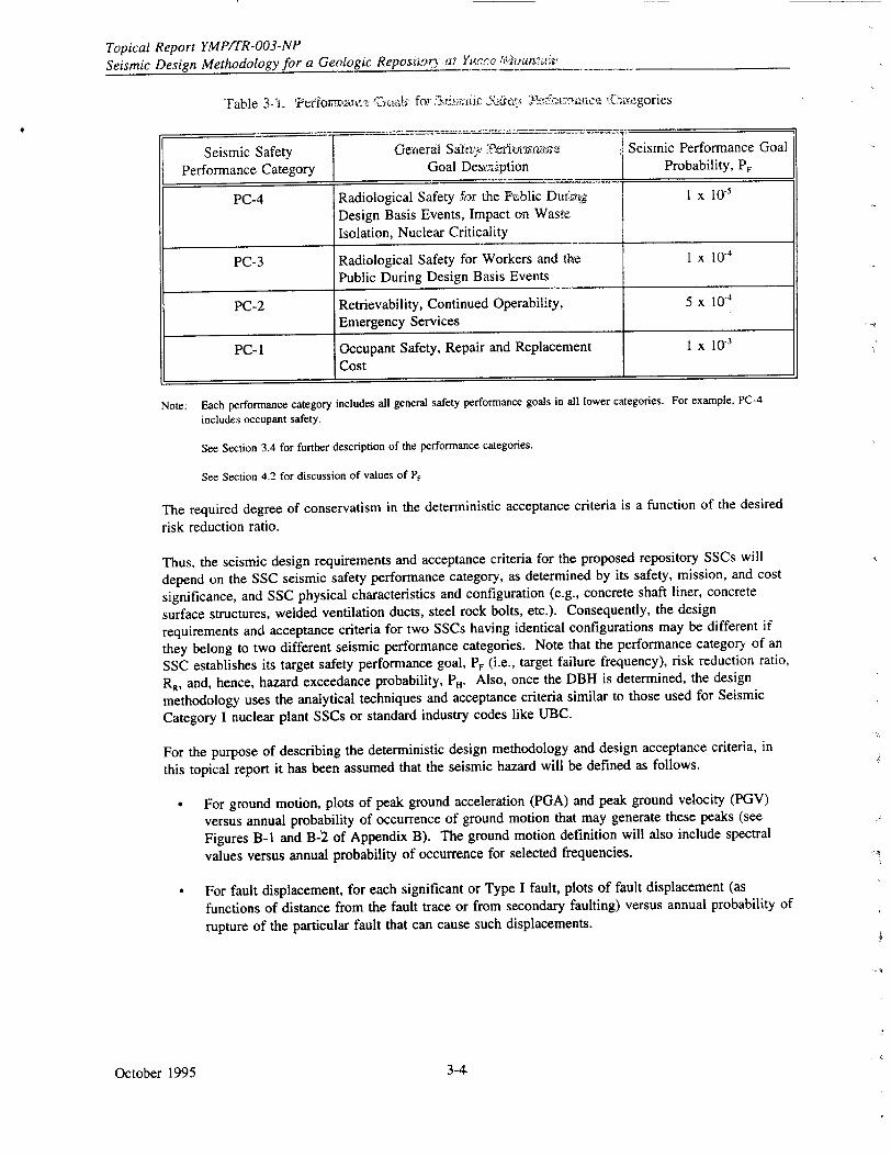
rable 3-i. .Pertorti-c • for ., .ic }Ž 'h; . -egories
Seismic Safety General Saht, • Seismic Performance Goal
Performance Category Goal Desxaiiption Probability, P,
Note: Each performance category includes all general safety performance goals in all lower categories. For example, PC-4
includes occupant safety.
See Section 3.4 for further description of the performance categories.
See Section 4.2 for discussion of values of PF
The required degree of conservatism in the deterministic acceptance criteria is a function of the desired
risk reduction ratio.
Thus, the seismic design requirements and acceptance criteria for the proposed repository SSCs will
depend on the SSC seismic safety performance category, as determined by its safety, mission, and cost
significance, and SSC physical characteristics and configuration (e.g., concrete shaft liner, concrete
surface structures, welded ventilation ducts, steel rock bolts, etc.). Consequently, the design
requirements and acceptance criteria for two SSCs having identical configurations may be different if
they belong to two different seismic performance categories. Note that the performance category of an
SSC establishes its target safety performance goal, P, (i.e., target failure frequency), risk reduction ratio,
RR, and, hence, hazard exceedance probability, P,. Also, once the DBH is determined, the design
methodology uses the analytical techniques and acceptance criteria similar to those used for Seismic
Category I nuclear plant SSCs or standard industry codes like UBC.
For the purpose of describing the deterministic design methodology and design acceptance criteria, in
this topical report it has been assumed that the seismic hazard will be defined as follows.
" For ground motion, plots of peak ground acceleration (PGA) and peak ground velocity (PGV)
versus annual probability of occurrence of ground motion that may generate these peaks (see
Figures B-1 and B-'2 of Appendix B). The ground motion definition will also include spectral
values versus annual probability of occurrence for selected frequencies.
"* For fault displacement, for each significant or Type I fault, plots of fault displacement (as
functions of distance from the fault trace or from secondary faulting) versus annual probability of
rupture of the particular fault that can cause such displacements.
October 1995
PC-4 Radiological Safety -far the F-ablic Duf.ii I x l1Design Basis Events, Impact on Waste
Isolation, Nuclear Criticality
PC-3 Radiological Safety for Workers and the 1 x 10⁻⁴
Public During Design Basis Events
PC-2 Retrievability, Continued Operability, 5 x 10⁻⁴
Emergency Services
PC- 1 Occupant Safety, Repair and Replacement 1 X 10⁻³
Cost
3-4
Topical Report YMP/IR-003-NP Seismic Design Methodology for a Geologic Repository at Yucca Mountain
The term "probabilistically determined seismic hazard" has been used often in this report to identify these plots. How these curves will be developed from site-specific data is outside the scope of this report, as this will be described in Seismic Topical Report III (see Section 1.3). The assumption here is that, once these hazard curves are developed, the design basis hazard will be deterministically treated for the purpose of engineering design, with the basic intent that the resulting design achieves at least a factor of safety of 1.5 against 10 percent failure probability when the SSC is subjected to a ground motion corresponding to PH.
3.3 ADVANTAGES OF USING THE SAFETY PGSD METHODOLOGY FOR THE YUCCA MOUNTAIN GROA
The potential repository facility at Yucca Mountain has some special design requirements and site geologic features for which the use of the PGSD method discussed above has special advantages. These advantages are discussed in the following paragraphs.
Although this topical report specifically addresses only preclosure seismic safety requirements, the repository facility must meet postclosure waste containment and isolation performance requirements that are related to protection of the public health and safety. The postclosure performance evaluation will be risk-based and will involve probabilistic considerations of potentially disruptive natural phenomena such
-as earthquakes. Since seismic risk will be a component of this facility performance evaluation, it is advantageous, if not essential, to be able to express the preclosure seismic safety performance of the facility SSCs in probabilistic terms. By expressing the preclosure seismic safety performance goals in terms of annual probability, they can be easily linked to the waste containment and isolation performance assessment.
Another advantage of using the PGSD method is related to the unique configuration of the repository facility and the existence of active faults at the Yucca Mountain site. The repository facility will encompass a large area and volume that will include long ramps, shafts, tunnels, and drifts. The site has known seismic faults that may cross some of these facilities even though, whenever feasible, the facilities will be laid out to avoid active faults. Thus, the design method must include consideration of the loads due to displacements associated with faults.
It is generally prudent to relocate a facility to avoid faults when the potential fault displacement is large, the probability of fault movement is high, and the consequence of fault displacement-related SSC failure is unacceptable. But, if the magnitude of fault displacement expected from fault movements within the frequency limit of the established safety performance goal is small enough to be accommodated in the design, or if the consequences of fault displacement-related SSC failure are within acceptable performance limits, a site that is otherwise desirable (based on other geological and climatological safety considerations) should not be abandoned because of the presence of such non-controlling seismic faults. The proposed method will permit rational design of SSCs that may be subjected to such low probability fault displacement hazards.
3.4 SEISMIC SAFETY PERFORMANCE CATEGORIES
Categorization or grouping of SSCs by their seismic safety performance requirement is a key step in the proposed performance goal-based seismic design method. Once the seismic safety performance category of an SSC is determined, its broad design objective in terms of a target safety performance goal (PF) is also established. In the method proposed here, SSCs are grouped into four seismic safety performance categories: PC-4, PC-3, PC-2, and PC-1. PC-4 SSCs have the most stringent seismic safety performance goalf (i.e., smallest failure probability, PF).
October 19953-5
Topical Report YMPITR-003-NP Seismic Design Methodology for a Geologic Repository at Yucca Mountain
The purpose of seismic safety performance categorization is to provide a gradation of various SSCs according to their safety importance such that more important SSCs are designed more stringently and their probable failure rates are lower. For the repository facilities at the Yucca Mountain site, SSC importance will be based on the following considerations.
* Radiological safety * Nuclear criticality • Waste isolation * Retrievability of stored fuel * General life and fire safety (nonradiological) * SSC repair and replacement cost and operability.
Radiological safety considerations include doses to the public and to workers, as well as releases of radioactive materials during normal operations. Dose considerations include doses to workers and the public during design basis events (see proposed rule change to 10 CFR Part 60 in Section 2.1.5).
Nuclear criticality safety refers to the need to ersure that the spent nuclear fuel and high-level waste are maintained in a subcritical configuration during storage, handling, transportation, and emplacement.
Waste isolation considerations reflect the need to prevent incidents during construction and preclosure operations that would significantly impact the postclosure waste isolation capability of the site in an adverse manner. As previously noted, these considerations do not include design features that might prevent or retard radionuclide releases during the postclosure time period. Those postclosure design considerations are included in repository and engineered barrier requirements but are not addressed in this report.
Retrievability of emplaced spent fuel and high-level waste is mandated by the Nuclear Waste Policy Act, as amended, and in 10 CFR Part 60. Retrieval may be necessary for any of the following three purposes.
* Performance confirmation during the caretaker period (about 100 years following onset of operations and initial receipt of waste). This may require selective retrieval of a small number of waste packages.
• Retrieval for waste isolation considerations. This may require retrieval of a small to a large number of waste packages, depending upon the degree and extent of undesirable circumstances, if any.
Retrieval for recovering economically valuable contents of the spent fuel. This may also require retrieval of a small to a large number of waste packages, depending on the circumstances. Note that retrieval for economic considerations is not a safety or performance issue and is therefore not addressed in 10 CFR Part 60. There are no plans at this time for retrieval for economic reasons.
General life and fire safety considerations reflect the desire to provide an enhanced level of protection for those design features that are related to the nonradiological health and safety of facility workers.
Finally, independent of safety considerations, cost and operability considerations may make it desirable to provide an enhanced level of protection for some SSCs.
In Sections 3.4.1 through 3.4.4, criteria are given for classifying Yucca Mountain repository SSCs into the four seismic performance categories.
October 1995 3-6
Topical Report YMP/TR-003-NP Seismic Design Methodology for a Geologic Repository at Yucca Mountain
3.4.1 Performance Category 4
The following criteria are based on radiological safety, waste isolation, and nuclear criticality
considerations. The criteria address doses during design basis events including consideration of system
interactions and monitoring and instrumentation.
SSCs whose proper functioning is required for the prevention or mitigation of an earthquake-induced accident that may result in a radiation dose to a member of the public in
excess of 5 rem (whole body or any organ) at or beyond the nearest boundary of the preclosure controlled area at any time until the completion of the permanent closure (see proposed rule
change to 10 CFR Part 60 in Section 2.1.5)
0 SSCs whose proper functioning is required for the prevention, detection, or mitigation of an
earthquake-induced accident that may compromise postclosure waste isolation.
• SSCs that are required to ensure against nuclear criticality in accordance with 10 CFR 60.131(b).
* SSCs whose proper functioning is essential to detect, monitor, and provide warning against the seismic failure of SSCs described by the items above.
A PC-3, PC-2, or PC-I SSC (hereafter called "source" SSC) whose failure during or following an earthquake may impair the functionality of a PC-4 SSC (hereafter called the "impacted" SSC). The source SSC will either be placed into the PC-4 category or designed such that any of the safety-related functions of the impacted PC-4 SSC are not impaired (see also Section 5.6).
To achieve the above-listed performance goals, the deformations in PC-4 SSCs due to the design basis
seismic event must be such that these SSCs continue to perform their safety function.
"3.4.2 Performance Category 3
"The following criteria are based on radiological safety considerations. They address doses during design basis events and radioactive effluents during normal operation.
0 SSCs whose proper functioning is required for the prevention or mitigation of an earthquake-induced accident that may result in a radiation dose to a member of the public and workers in excess of those limits specified in 10 CFR Part 20 at any time until permanent closure (see proposed rule change to 10 CFR Part 60 in Section 2.1.5).
- SSCs whose proper functioning is required for the prevention or mitigation of an earthquake-induced accident that may result in the release of radioactive materials to unrestricted "areas in excess of the limits specified in 10 CFR Part 20 at any time until permanent closure.
* A PC-2 or PC-1 source SSC whose failure during or following an earthquake may impair the functionality of a PC-3 SSC. The source SSC will either be placed into the PC-3 category or designed such that any of the safety-related functions of the impacted PC-3 SSC are not impaired "(see also Section 5.6).
To achieve the above-listed performance goals, the deformations in PC-3 SSCs due to the design basis seismic event must be such that the SSCs continue to perform their safety function.
October 19953-7
Topical Report YMPITR-OO3-NP Seismic Design Methodology for a Geologic Repository at Yucca Mountain
3.4.3 Performance Category 2
The following criteria are based on retrievability of spent fuel and high-level waste, emergency systems associated with general life safety, repair and replacement costs, and operability.
SSCs whose proper functioning during and after an earthquake are essential for retrievability, safe transportation, and safe on-site storage and handling of waste packages. Examples of such SSCs are ground support systems for drifts and ramps that will be used for retrieval and transportation, associated drift inverts and rails, and shielding doors.
" SSCs whose seismic failure may result in loss of function of any emergency handling, hazard recovery, fire suppression, fire monitoring, fire protection, emergency preparedness, communication, or emergency power system needed to protect the health and safety of the facility workers.
"• SSCs whose seismic failure could prevent rapid egress of facility workers from underground drifts and ramps.
* SSCs with high repair and replacement costs associated with seismic failure. Note that this consideration is subjective and the grading is qualitative; discretion is provided to the designer for invoking this criterion.
To achieve the above-listed performance goals, the deformations in PC-2 SSCs due to the design basis seismic event must be such that the SSC function can be restored with little or no repair effort.
3.4.4 PerformanLe Category 1
The following criteria are based on general life safety and repair and replacement costs.
* SSCs whose seismic failure may endanger general life safety of the occupant, including the facility worker.
* SSCs with substantial repair and replacement costs associated with seismic failure. Note that this consideration is subjective and the grading is qualitative; discretion is provided to the designer for invoking this criterion.
To achieve the general life safety goal, PC-1 SSCs must not collapse when subjected to the design basis seismic event.
3.5 DETERMINATION OF SEISMIC SAFETY PERFORMANCE CATEGORY
The seismic safety performance category of an SSC is determined based on the considerations discussed in Section 3.4. Each SSC is placed in the highest applicable category. For example, if an SSC has general life safety functions (that would place it in PC-i), and radiological safety functions (that would place it in PC-3), then that SSC will be placed in the PC-3 category.
For illustration, the seismic safety performance categorization process for a few of the major SSCs in the repository facilities is described in Appendix A. This categorization is preliminary, pending a systematic accident evaluation study for the facility.
October 1995 3-8
Topical Report YMP/TR-003-NP Seismic Design Methodology for a Geologic Repository at Yucca Mountain
4.0 BASIS FOR THE SAFETY PERFORMANCE GOAL-BASED SEISMIC DESIGN METHOD
After the design basis seismic hazard (DBH) is established (see Section 3.0), the performance
goal-based seismic design (PGSD) method uses a deterministic design, analysis, and evaluation
procedure. The basic concepts on which this deterministic design method is based are briefly presented
in Section 4.1 (details are presented in Appendix B). The determination of numerical target
performance goal (PF) values, risk reduction ratios (RR) and the design basis seismic hazard
exceedance probability (PH) are discussed in Section 4.2. How the seismic design criteria described
here compare with the Nuclear Regulatory Commission's (NRC) current criteria for nuclear power
plant facilities is discussed in Section 4.3 and in Appendix C.
The basic concepts described in Section 4.1 below have been developed based on nuclear and general
industry experience in designing structures, systems, and components (SSCs) that are subjected to
seismic vibratory ground motion. Even though these concepts are philosophically applicable for
seismic design of SSCs that are subject to fault displacements, the numerical values cited or used in
Sections 4.1 and 4.2, especially those related to SSC fragility and seismic hazard uncertainties, may not be applicable to fault displacement design of SSCs. As such, Sections 4.1, 4.2, and 4.3, as well
as Sections 5, 6, 7, and 8 are applicable to SSC design for vibratory seismic motions only; SSC design for fault displacements is addressed in Section 9.
4.1 BASIC CONCEPTS
The basic objective of the PGSD method is to limit the failure probability of an SSC to a specified
low value that is consistent with its failure consequences. Specifically, the objective is to approximately meet the target performance goals for the four SSC categories listed in Table 3-1. However, to formally demonstrate that an SSC meets a performance goal (or failure rate), a
probabilistic risk assessment (PRA)-type study would be needed which, as was noted in Section 3.1,
is not practical in an iterative design process of a new facility. To circumvent this difficulty and also
to meet the basic objective, the PGSD method uses
"* Seismic design inputs (ground motion values and fault displacements) that are based on probabilistically determined seismic hazard (see Topical Report I, DOE 1994a), and
"* a deterministic design evaluation methodology and design acceptance criteria that are primarily based on applicable industry codes and standards, augmented by necessary modifications such that the target performance goals are approximately met.
From Equation 3-1 (see Section 3.2) it is observed that the seismic performance goal PF for a given performance category can be achieved by a combination of P, (which defines the design basis seismic hazard, DBH) and R1, provided that the RR value is consistent with the degree of conservatism in the design evaluation methodology and the acceptance criteria used. Table 4-1 shows the RR values for the four seismic performance categories. Section 4.2 describes how these values were established. The method of establishing compatibility of these RR values with the degree
of conservatism in the design methodology and design acceptance criteria (described in Sections 5 through 9) is briefly described below; details are provided in Appendix B.
To achieve the Rk values shown in Table 4-1, sufficient conservatism must be included in the seismic
design acceptance criteria for each performance category. To determine the level of conservatism in the
criteria necessary to achieve a given R., it is necessary to define a mean seismic fragility curve for the SSC that is designed by using these criteria. This mean seismic fragility curve describes the probability
of unacceptable performance (or failure) versus the seismic load (ground motion or fault displacement) level.
October 19954-1-
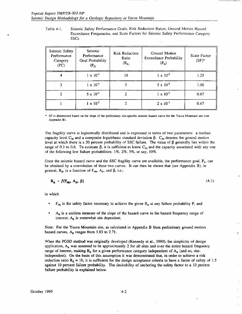
Topical Report YMPITR-003-NP Seismic Design Methodology for a Geologic Repository at Yucca Mountain
Table 4-1. Seismic Safety Performance Goals, Risk Reduction Ratios, Ground Motion Hazard Exceedance Frequencies, and Scale Factors for Seismic Safety Performance Category SSCs
* SF is determined based on the slope of the preliminary site-specific seismic hazard curve for the Yucca Mountain site (see Appendix B).
The fragility curve is lognormally distributed and is expressed in terms of two parameters: a median capacity level C, and a composite logarithmic standard deviation P3. C, denotes the ground motion level at which there is a 50 percent probability of SSC failure. The value of 13 generally lies within the range of 0.3 to 0.6. To estimate P3, it is sufficient to know C, and the capacity associated with any one of the following low failure probabilities: 1%, 2%, 5%, or say, 10%.
Once the seismic hazard curve and the SSC fragility curve are available, the performance goal, PF, can be obtained by a convolution of these two curves. It can then be shown that (see Appendix B), in general, RR, is a function of FPR, AR, and P3, i.e.;
RR = f(Fpt, AR, P3) (4-1)
in which
"• FPR is the safety factor necessary to achieve the given RR at any failure probability P, and
"* AR is a unitless measure of the slope of the hazard curve in the hazard frequency range of interest; AR is somewhat site dependent.
Note: For the Yucca Mountain site, as calculated in Appendix B from preliminary ground motion hazard curves, AR ranges from 1.83 to 2.71.
When the PGSD method was originally developed (Kennedy et al., 1990), for simplicity of design application, AR was assumed to be approximately 2 for all sites and over the entire hazard frequency range of interest, making RR for a given performance category independent of AR (and so, siteindependent). On the basis of this assumption it was demonstrated that, in order to achieve a risk reduction ratio RR = 10, it is sufficient for the design acceptance criteria to have a factor of safety of 1.5 against 10 percent failure probability. The desirability of anchoring the safety factor to a 10 percent failure probability is explained below.
October 1995 4-2
Topical Report YMPITR-003-NP Seismic Design Methodology for a Geologic Repository at Yucca Mountain
Subsequent studies (LLNL and BNL, 1994) showed that the above assumption of AR = 2, may not be appropriate for all sites and for all hazard frequencies of interest. A compensating scale factor SF was introduced such that
* The dependence of RR on AR can be explicitly accounted for by using Equation 4-1 and actual slopes of site-specific hazard curves
* The original goal of having a factor of safety 1.5 against 10 percent failure probability can be met for target RR values differem than 10.
SF is used to scale the design basis hazard level.
As is demonstrated in Appendix B, the SF values in Table 4-1 appear to be slightly conservative when applied to the Yucca Mountain site.
The dependence of RR on P in Equation 4-1 is accounted for somewhat differently because actual fragility curves for most SSCs are generally not available. As P3 is known to lie in the range of 0.3 to 0.6, it is considered desirable to minimize the variation of RR with P3 over this range. It has been shown (see LLNL and BNL, 1994) that if FPR is defined at the failure probability of 10 percent, i.e., at CIO (instead of at a high value, such as C5o, or at a very low value, such as C,), the variation in R, with 13 is minimum for AR values between 2 and 4. Hence, the values of RR and SF are established on the basis of 10 percent failure capacity.
This seismic demand factor is defined as
FD = 1.5 SF (4-2)
The above discussion on the basic concepts of the PGSD method leads to the conclusion that, if the repository facility SSCs are designed with the basic intention of achieving a less than 10 percent probability of unacceptable performance when subjected to a scaled design basis hazard (SDBH), defined by
SDBH = FD (DB-) (4-3)
then the target R, and PF values listed in Table 4-1 will be achieved.
The SF values listed in Table 4-1 meet the above basic intent. However, the design engineer does not need to use these SF and FD values explicitly in the design calculation for all SSC performance categories. The actual application of these two factors in the design evaluation methodology and acceptance criteria for SSCs other than underground openings and ground support systems is explained below.
"• For PC-I and PC-2 SSCs, it can be shown that SF is 0.67 (see Figure B-4), and therefore FD = 1.0. Hence, seismic loads corresponding to PH are the design basis seismic loads and no scaling of these loads is needed to satisfy the basic intent.
" For PC-3 SSCs, SF is 1.0 (see Table 4-1), and FD = 1.5. This factor has been built into the design methodology for PC-3 and PC-4 SSCs. Hence, when these criteria are used to design PC-3 SSCs, seismic loads corresponding to PH are the design basis seismic loads, and no scaling of these loads is needed to meet the basic intent.
October 19954-3,
Topical Report YMP/TR-003-NP Seismic Design Methodology for a Geologic Repository at Yu7rra Mountain_
For PC-4 SS•C, SF is 1.2.5 'i1, '-itTte 4-1. . nJ f,.z fi U i"J. -= LI, Of this, the basic safety
factor of 1.5 is alread3y inciuded ir. nd.ýt &jsign n-t~bodolQ•.l•y ••i. ý':2 t, PC-4 SSCs. The
remaining factor SF = 1.25 Ji usei • ;multiply t-1, : 'p.txt ;cvrr ,.tionding to PH to obtain
design basis seismic loads.
For designing underground openings and gmenird suppr(t SSCs, to ,•,rahstan1 ibratory ground motion the
design methodology and acceptance criteria described in Section 6 &. ihiis .report use the same PF, R,
(and, hence, the same P,) and SF values as given in Table 4-1, 't~ h ,be acceptance criteria are different
(equally or more conservative) than those for surface facilities (de:rfibed in Section 5). In addition, in
all cases, underground openings and ground support SSCs will have their design basis seismic loads
increased by multiplying the seismic inputs corresponding to P, wffh a seismic demand factor of F, =
1.5 SF. Since the acceptance criteria for these SSCs are equally or more conservative than those for
surface SSCs, and, in addition, the basic safety factor 1.5 is explicitly used, the basic intent of achieving
a factor of safety of 1.5 against 10 percent failure probability will be satisfied by a wide margin.
For this report it has been assumed that, in Appendix B, the range of A, values considered in
establishing the SF and R, combinations of Table 4-1 is broad enough to account for SSC period
dependence of these combinations. This assumption will be verified after a site-specific ground motion
response spectrum is developed in Seismic Topical Report III, and, if necessary, the Table 4-1 SF
values will be updated.
4.2 SAFETY PERFORMANCE GOALS, RISK REDUCTION FACTORS, AND DESIGN BASIS
HAZARD LEVELS
The performance goal (PF) for an SSC is numerically expressed as its target annual probability of
unacceptabL behavior, or simply its target annual failure probability. All SSCs belonging to a particular
seismic performance category should have the same target seismic performance goal (i.e., their probable
annual failure rate due to seismic hazard should be of the same order). This failure rate will depend on
design and evaluation methodology, design acceptance criteria, return period for the design basis hazard,
and the uncertainties associated with SSC material properties and construction processes. Empirical
evaluation of SSC performance and failure provides a practical method for assessing failure rates.
Accordingly, the overall safety performance of nuclear power plants, as determined from PRAs, is used
to establish P, for PC-4 SSCs, and the safety performance of buildings designed in accordance with the
Uniform Building Code (UBC) is used to establish P. for PC-1 SSCs. P, values for PC-3 and PC-2
SSCs are interpolated from PC-1 and PC-4, based on a graded approach.
Numerical performance goals (PF), risk reduction factors (RR), seismic hazard frequencies (P,) and scale
factors (SF) for the four seismic performance categories are listed in Table 4-1. Methods used in
determining these values are described in the following subsections.
4.2.1 Seismic Performance Category 4 (PC-4)
A repository SSC that must retain functionality to provide reasonable assurance of compliance with
preclosure radiological safety objectives will be classified as seismic performance category 4 (PC-4). A
comparison of the pressure and temperature loads imposed by the radioactive waste inventory, to those
that nuclear power plant Seismic Category I SSCs must withstand, clearly shows that the repository
facility SSCs have significantly less radiological safety importance. Thus, the requirement to design
repository facility PC-4 SSCs such that their mean annual failure rate (i.e., performance goal) is
approximately equal to that of nuclear power plant Seismic Category I SSCs assures conservative
performance with respect to the facility preclosure seismic safety performance objectives (see Section
2.1.5). For this reason, and in order to adopt established, familiar nuclear design procedures and
criteria, the preclosure seismic safety performance goal for SSCs in PC-4 is established to be
approximately equal to that of nuclear power plant Seismic Category I SSCs.
October 1995 4-4
Topical Report YMP/TR-003-NP Seismic Design Methodology for a Geologic Repository at Yucca Mountain
The mean annual failure rate of Seismic Category I SSCs in nuclear power plants has been obtained from approximately 30 PRAs of nuclear plant units. These PRA results show that the mean annual frequency of earthquake-induced core damage (i.e., failure) lies within the range 2 x 10.6 and 5 x 10'. The median value of these mean annual failure rates is about I x 10-5 (Kennedy, 1993). On the basis of these PRA results, the numerical performance goal (P,) for the repository SSCs classified as PC-4 is established at the mean annual rate of 1 x 10'- per year.
The design and evaluation methodology and design acceptance criteria for PC-4 SSCs in the repository facilities are similar to those currently used for Seismic Category I SSCs in nuclear power plants. Thus, the degree of conservatism, as measured by the risk reduction factor RR (see Section 3.2) for Seismic Category I SSCs can be considered to be equivalent to PC-4 SSCs of the repository. To estimate RR for existing Seismic Category I SSCs, the results of seismic PRA studies of over 30 existing nuclear power plants were used. From these studies it was determined that RR ranges from 10 to 240 (Short et al., 1990) with a median value of about 22. Hence, it is reasonable to conclude that if the design and evaluation methodology and acceptance criteria for PC-4 SSCs of the repository are made comparable to those of Seismic Category I SSCs (of nuclear power plants), and a low R, value (lower than 22) is used, then the design seismic hazard exceedance probability, PH = RR x PF, (see Section 3.2) and the resulting PC-4 SSC design basis will have conservatism comparable to that of existing nuclear power plant Seismic Category I SSCs. For PC-4 repository SSCs, an RR value of 10 is assumed which results in a design PH value of 10 x Pr, or 1 x I0g4.
Modern seismic hazard curves show that the variation of the hazard curve slope from site to site in various regions of the United States, and between various frequency ranges, can be significant. Consequently, the use of site-specific hazard curve slopes can improve the design accuracy (LLNL and BNL, 1994). For repository facilities, therefore, site specific hazard curve slope values (at appropriate frequency ranges) will be used to calculate the scale factors such that the assumed risk reduction factors (10 for PC-4) are achieved (see also Section 4.1). The method of calculating this scale factor is described in Appendix B of this report. The scale factor is used to multiply postulated seismic demand before the demand is compared with the SSC capacity. For PC-4 SSCs a preliminary scale factor has been determined as 1.25 using the Exploratory Studies Facility seismic hazard curve.
4.2.2 Seismic Performance Category 3 (PC-3)
In Sections 3.4 and 3.5 it is noted that PC-3 SSCs may have significant radiological safety importance but the failure consequences of a PC-3 SSC are far less significant than for a PC-4 SSC. PC-3 SSC failure can result only in a public radiation exposure that is very low. Fatality risk at such a low level of radiation is insignificant (NCRP, 1971; Glasstone, 1962). The risk difference between 5 rem and 10 CFR Part 20 limits is about an order of magnitude. Based on this rationale, the safety performance goal of PC-3 SSCs has been established one order of magnitude less than that for PC-4 SSCs, at the mean annual rate of 1 x 10-. This target seismic safety performance goal can be achieved by several combinations of RR, PH, and scale factor (SF). SF will account for the actual slope of the site-specific hazard curve. Considering the various options, it is shown in Appendix B that for PC-3 SSCs an R, value of 5 should be used to satisfy conservatively the basic design intent. Thus, the hazard level appropriate for design of PC-3 SSCs has a mean annual exceedance probability of 5 x 10-'. Even though this PC-3 RR value is different from the PC-4 RR value of 10, the design and analysis methods and acceptance criteria for PC-3 SSCs will be identical to those for PC-4 SSCs, except that the scale factor will be different. The scale factor will be based on a site-specific mean hazard curve slope in the hazard exceedance frequency range of 1 x 10⁴ (i.e., P.) and 5 x 10⁻⁴ (i.e., PH), to achieve RR of 5. As shown in Appendix B, the scale factor for PC-3 SSCs is 1.0 based on the Exploratory Studies Facility mean hazard curve (see Table 4-1).
October 1995
Topical Report YMPITR-003-NP
Seismic Design Methodology for a Geologic Repository at Yucca Mountain
4.2.3 Seismic Performance Categories 1 (PC-i) and 2 (PC-2)
From Section 3.4.4, it is noted that a general use SSC that does not perform any radiological safety
function, spent fuel retrieval function, or any other special function will be assigned seismic
performance category PC-1. Thus, the importance or significance of PC-1 SSCs in repository facilities
is identical to that of UBC general use facilities with importance factor equal to unity. Accordingly,
PC-I SSCs of the repository will be designed such that their performance goal (i.e., probable annual
seismic failure rate) is the same as that of UJBC general use facilities.
From Section 3.4.2, it is noted that the overall importance of a PC-2 SSC is more than that of a PC-1
SSC but less than that of a PC-3 SSC. Thus, the target annual performance goal (PF) for PC-2 SSCs
has been established as 5 x 10"', which is between the PF value for PC-i and PC-3 (i.e., between
10 x 10.' and 1 x 10"'). Also, for simplicity, RR for PC-2 is kept the same as that for PC-I (i.e., RR
2), since both PC-I and PC-2 SSCs will be designed following UBC (or equivalent) design rules. For
RR = 2 and P, in the range 1 x 10"4 to 5 x 10⁴, from Appendix B, the scale factor SF is 0.67 and thus
from Equations 4-2 and 4-3
SDBH = DBH (4-4)
Achieving a risk reduction ratio of 2 is consistent with a 10 percent probability of unacceptable
performance when an SSC is subjected to the DBH. Based on experience from past earthquakes, the
use of national building codes such as the UBC results in less than a 10 percent probability of
unacceptable performance when an SSC is subjected to ground motion which corresponds to the design
ZC (Scaled Base Shear) for the UBC. The Applied Technology Council in ATC-3 (ATC, 1978) has
suggested the relationship shown in Figure 4-1 between probability of failure and the ratio of the actual
earthquake ground motion to the code design ground motion. This ATC-3 estimate suggests only a one
to two percent conditional probability of life threatening damage-when the actual earthquake ground
motion is equal to the design ground motion. However, this estimate is uncertain. Therefore, in the
proposed method for Yucca Mountain it has been conservatively assumed that the probability of
unacceptable performance could be as high as 10 percent when an SSC that is designed to the UBC is
subjected to ground motion equal to the DBH. Thus, UBC seismic design provisions provide at least a
risk reduction ratio RR of 2.
Therefore, for seismic design of the repository, the UBC provisions for general use and essential
facilities will be used for the seismic evaluation and design of PC-i and PC-2 SSCs, respectively,
except that seismic design inputs will be based on the hazard for the target (mean annual) exceedance
probabilities (2 x 10r3 and 1 x 10"3, respectively) rather than on values taken from UBC seismic zonation
maps. The PC-1 hazard exceedance probability is consistent with the UBC target of 10 percent
probability of exceedance in 50 years, whereas the PC-2 hazard exceedance probability is more
conservative than the UBC value.
In summary, the PC-1 seismic provisions are equal to the UBC general-use seismic provisions, whereas
the PC-2 seismic provisions are slightly more conservative than the UBC essential facility provisions.
October 1995 4-6
Topical Report YMP/TR-003-NP Seismic Design Methodology for a Geologic Repository at Yucca Mountain
4.3 COMPARISON OF CURRENT NRC SEISMIC DESIGN CRITERIA FOR NUCLEAR PLANTS AND THE PROPOSED REPOSITORY SEISMIC DESIGN CRITERIA
The seismic design method proposed in this document is basically similar to the current method of
designing nuclear power plant SSCs. In both methods, given the DBH, the method of predicting the
earthquake-induced loads (forces, moments, or stresses) and the method of determining the strengths and capacities are deterministic. Thus, neither method accounts for the associated design uncertainties in an
explicit or a probabilistic way. Moreover, both methods use the same basic industry-accepted codes and standards for design. However, somne differences exist in the detail of the method of determining design
loads (demands) and in establishing acceptance criteria. These are discussed in detail in Appendix C.
October 19954-7.
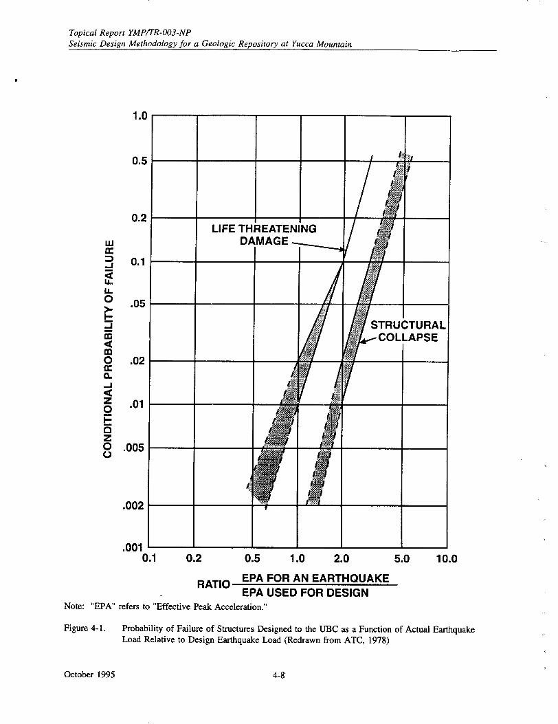
Topical Report YMP/TR-003-NP Seismic Design Methodology for a Geologic Repository at Yucca Mountain
1.0
0.5
0.2
w
-j
-I 0
0 Cr
n
z 0
z 0 0
C.)
0.1
.05
.02
.01
.005
.002
.0010.1 0.2 0.5 1.0 2.0 5.0 10.0
RATIO EPA FOR AN EARTHQUAKE EPA USED FOR DESIGN
Note: "EPA" refers to "Effective Peak Acceleration."
Figure 4-1. Probability of Failure of Structures Designed to the UBC as a Function of Actual Earthquake Load Relative to Design Earthquake Load (Redrawn from ATC, 1978)
October 1995 4-&
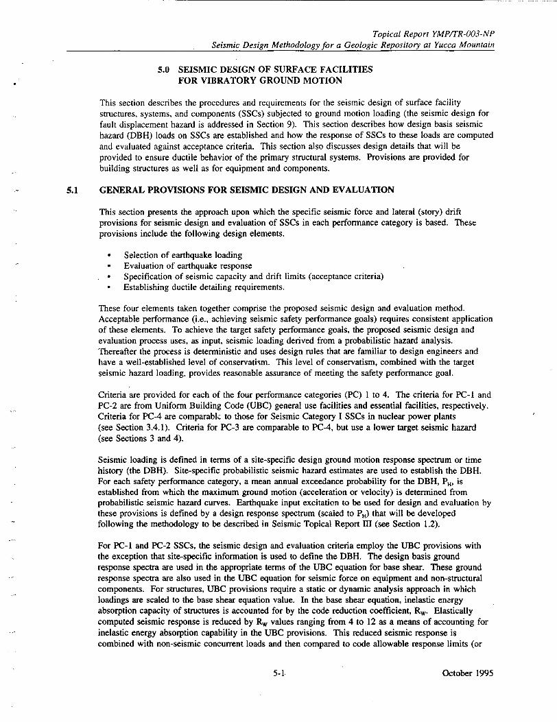
Topical Report YMPITR-003-NP Seismic Design Methodology for a Geologic Repository at Yucca Mountain
5.0 SEISMIC DESIGN OF SURFACE FACILITIES FOR VIBRATORY GROUND MOTION
This section describes the procedures and requirements for the seismic design of surface facility structures, systems, and components (SSCs) subjected to ground motion loading (the seismic design for fault displacement hazard is addressed in Section 9). This section describes how design basis seismic hazard (DBH) loads on SSCs are established and how the response of SSCs to these loads are computed and evaluated against acceptance criteria. This section also discusses design details that will be provided to ensure ductile behavior of the primary structural systems. Provisions are provided for building structures as well as for equipment and components.
5.1 GENERAL PROVISIONS FOR SEISMIC DESIGN AND EVALUATION
This section presents the approach upon which the specific seismic force and lateral (story) drift provisions for seismic design and evaluation of SSCs in each performance category is based. These provisions include the following design elements.
* Selection of earthquake loading * Evaluation of earthquake response 0 Specification of seismic capacity and drift limits (acceptance criteria) 9 Establishing ductile detailing requirements.
These four elements taken together comprise the proposed seismic design and evaluation method. Acceptable performance (i.e., achieving seismic safety performance goals) requires consistent application of these elements. To achieve the target safety performance goals, the proposed seismic design and evaluation process uses, as input, seismic loading derived from a probabilistic hazard analysis. Thereafter the process is deterministic and uses design rules that are familiar to design engineers and have a well-established level of conservatism. This level of conservatism, combined with the target seismic hazard loading, provides reasonable assurance of meeting the safety performance goal.
Criteria are provided for each of the four performance categories (PC) I to 4. The criteria for PC-1 and PC-2 are from Uniform Building Code (UBC) general use facilities and essential facilities, respectively. Criteria for PC-4 are comparablc to those for Seismic Category I SSCs in nuclear power plants (see Section 3.4.1). Criteria for PC-3 are comparable to PC-4, but use a lower target seismic hazard (see Sections 3 and 4).
Seismic loading is defined in terms of a site-specific design ground motion response spectrum or time history (the DBH). Site-specific probabilistic seismic hazard estimates are used to establish the DBH. For each safety performance category, a mean annual exceedance probability for the DBH, PH, is established from which the maximum ground motion (acceleration or velocity) is determined from probabilistic seismic hazard curves. Earthquake input excitation to be used for design and evaluation by these provisions is defined by a design response spectrum (scaled to PH) that will be developed following the methodology to be described in Seismic Topical Report III (see Section 1.2).
For PC-1 and PC-2 SSCs, the seismic design and evaluation criteria employ the UBC provisions with the exception that site-specific information is used to define the DBH. The design basis ground response spectra are used in the appropriate terms of the UBC equation for base shear. These ground response spectra are also used in the UBC equation for seismic force on equipment and non-structural components. For structures, UBC provisions require a static or dynamic analysis approach in which loadings are scaled to the base shear equation value. In the base shear equation, inelastic energy absorption capacity of structures is accounted for by the code reduction coefficient, Rw. Elastically computed seismic response is reduced by R, values ranging from 4 to 12 as a means of accounting for inelastic energy absorption capability in the UBC provisions. This reduced seismic response is combined with non-seismic concurrent loads and then compared to code allowable response limits (or
October 19955-1.
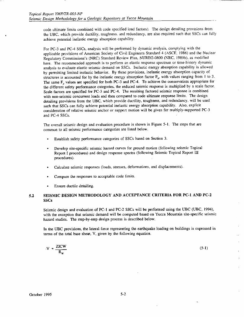
Topical Report YMP/TR-003-NP Seismic Design Methodology for a Geologic Repository at Yucca Mountain
code ultimate limits combined with code specified load factors). The design detailing provisions from the UBC, which provide ductility, toughness, and redundancy, are also required such that SSCs can fully
achieve potential inelastic energy absorption capability.
For PC-3 and PC-4 SSCs, analysis will be performed by dynamic analysis, complying with the
applicable provisions of American Society of Civil Engineers Standard 4 (ASCE, 1986) and the Nuclear
Regulatory Commissions's (NRC) Standard Review Plan, NUREG-0800 (NRC, 1989b), as modified
here. The recommended approach is to perform an elastic response spectrum or time-history dynamic
analysis to evaluate elastic seismic demand on SSCs. Inelastic energy absorption capability is allowed
by permitting limited inelastic behavior. By these provisions, inelastic energy absorption capacity of
structures is accounted for by the inelastic energy absorption factor F,, with values ranging from 1 to 3.
The same F. values are specified for both PC-3 and PC-4. To achieve the conservatism appropriate for
the different safety performance categories, the reduced seismic response is multiplied by a scale factor.
Scale factors are specified for PC-3 and PC-4. The resulting factored seismic response is combined with non-seismic concurrent loads and then compared to code ultimate response limits. The design
detailing provisions from the UBC, which provide ductility, toughness, and redundancy, will be used
such that SSCs can fully achieve potential inelastic energy absorption capability. Also, explicit consideration of relative seismic anchor or suppoAt motion will be given for multiply-supported PC-3 and PC-4 SSCs.
The overall seismic design and evaluation procedure is shown in Figure 5-1. The steps that are common to all seismic performance categories are listed below.
* Establish safety performance categories of SSCs based on Section 3.
Develop site-specific seismic hazard curves for ground motion (following seismic Topical
Report I procedures) and design response spectra (following Seismic Topical Report IIn procedures).
Calculate seismic responses (loads, stresses, deformations, and displacements).
* Compare the responses to acceptable code limits.
* Ensure ductile detailing.
5.2 SEISMIC DESIGN METHODOLOGY AND ACCEPTANCE CRITERIA FOR PC-1 AND PC-2 SSCs
Seismic design and evaluation of PC-I and PC-2 SSCs will be performed using the UBC (UBC, 1994), with the exception that seismic demand will be computed based on Yucca Mountain site-specific seismic hazard studies. The step-by-step design process is described below.
In the UBC provisions, the lateral force representing the earthquake loading on buildings is expressed in terms of the total base shear, V, given by the following equation.
•- ZICW (5-1) Rw
October 1995 5-Z
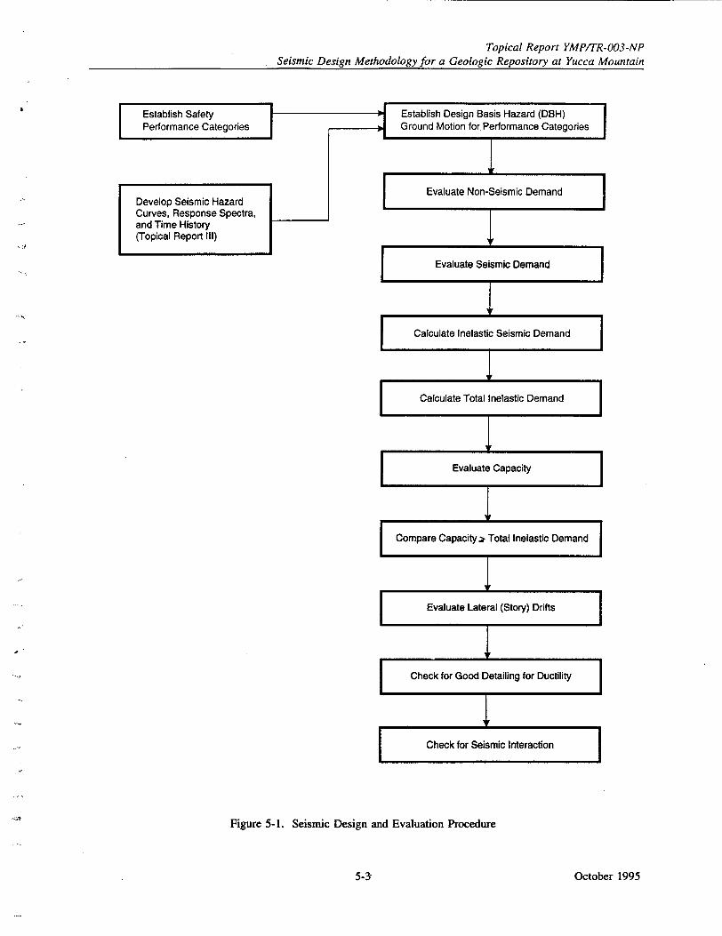
Topical Report YMP/TR-003-NP Seismic Design Methodology for a Geologic Repository at Yucca Mountain
Figure 5-1. Seismic Design and Evaluation Procedure
October 19955-3-
Topical Report YMP/TR-003-NP Seismic Design Methodology for a Geologic Repository at Yucca Mountain
in which
Z = a seismic zone factor equivalent ýo peak ground acceleration I = a factor accounting for the importance of the facility C = a spectral amplification factor W = the total weight of the facility Rw = code reduction coefficient, a reduction factor to account for energy absorption capability
of the SSC, which results in element forces that represent inelastic seismic demand, D,1
The steps in the procedure for PC-1 and PC-2 SSCs are as follows.
"* Evaluate element forces for non-seismic loads, DNs, expected to be acting concurrently with an earthquake.
" Evaluate element forces, Ds5 , for earthquake loads.
- Static force method, where V is applied as a load distributed over the height of the structure for regular facilities, or dynamic force method, for irregular facilities as described in the UBC.
- In either case, the total base shear is given by Equation 5-I, where the parameters are evaluated as follows.
0 Z is the peak ground acceleration from site-specific seismic hazard at the following exceedance probabilities from Table 4-1.
PC-1: 2 x 10⁻³
PC-2: I x 10-3
"* C is the spectral amplification at the fundamental period of the facility from the five percent damped median site response spectrum. For fundamental periods lower than the
period at which the maximum spectral acceleration occurs, ZC will be taken as the maximum spectral acceleration.
For systems and components, spectral amplification is accounted for by Cp in the UBC equipment force equation, as discussed in Section 5.4.
"* If ZC, determined from a site-specific assessment, is less than that given by UBC provisions, the latter will be used in the design.
"• The importance factor, I, will be taken as
PC-l, I = 1.0
PC-2, I = 1.25
"* For structures, reduction factors, Rw, are shown in Table 5-1 (from UBC). For systems and components, the reduction factor is implicitly included in C,.
Combine responses from various loadings (DNs and Ds5 ) to evaluate total, inelastic-factored demand, D-,, by code-specified load combination rules (e.g., load factors for ultimate strength design or unit load factors for allowable stress design).
October 1995 5-4
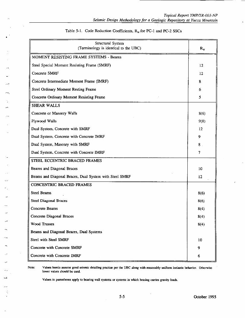
Topical Report YMPITR-003-NP Seismic Design Methodology for a Geologic Repository at Yucca Mountain
Table 5-1. Code Reduction Coefficients, Rw for PC-i and PC-2 SSCs
Structural System
(Terminology is identical to the UBC) R,
MOMENT RESISTING FRAME SYSTEMS - Beams
Steel Special Moment Resisting Frame (SMRF) 12
Concrete SMRF 12
Concrete Intermediate Moment Frame (IMRF) 8
Steel Ordinary Moment Resting Frame 6
Concrete Ordinary Moment Resisting Frame 5
SHEAR WALLS
Concrete or Masonry Walls 8(6)
Plywood Walls 9(8)
Dual System, Concrete with SMRF 12
Dual System, Concrete with Concrete IMRF 9
Dual System, Masonry with SMRF 8
Dual System, Concrete with Concrete IMRF 7
STEEL ECCENTRIC BRACED FRAMES
Beams and Diagonal Braces 10
Beams and Diagonal Braces, Dual System with Steel SMRF 12
CONCENTRIC BRACED FRAMES
Steel Beams 8(6)
Steel Diagonal Braces 8(6)
Concrete Beams 8(4)
Concrete Diagonal Braces 8(4)
Wood Trusses 8(4)
Beams and Diagonal Braces, Dual Systems
Steel with Steel SMRF 10
Concrete with Concrete SMRF 9
Concrete with Concrete IMRF 6
Note: Values herein assume good seismic detailing practice per the UBC along with reasonably uniform inelastic behavior. Otherwise
lower values should be used.
Values in parentheses apply to bearing wall systems or systems in which bracing carries gravity loads.
October 19955-5
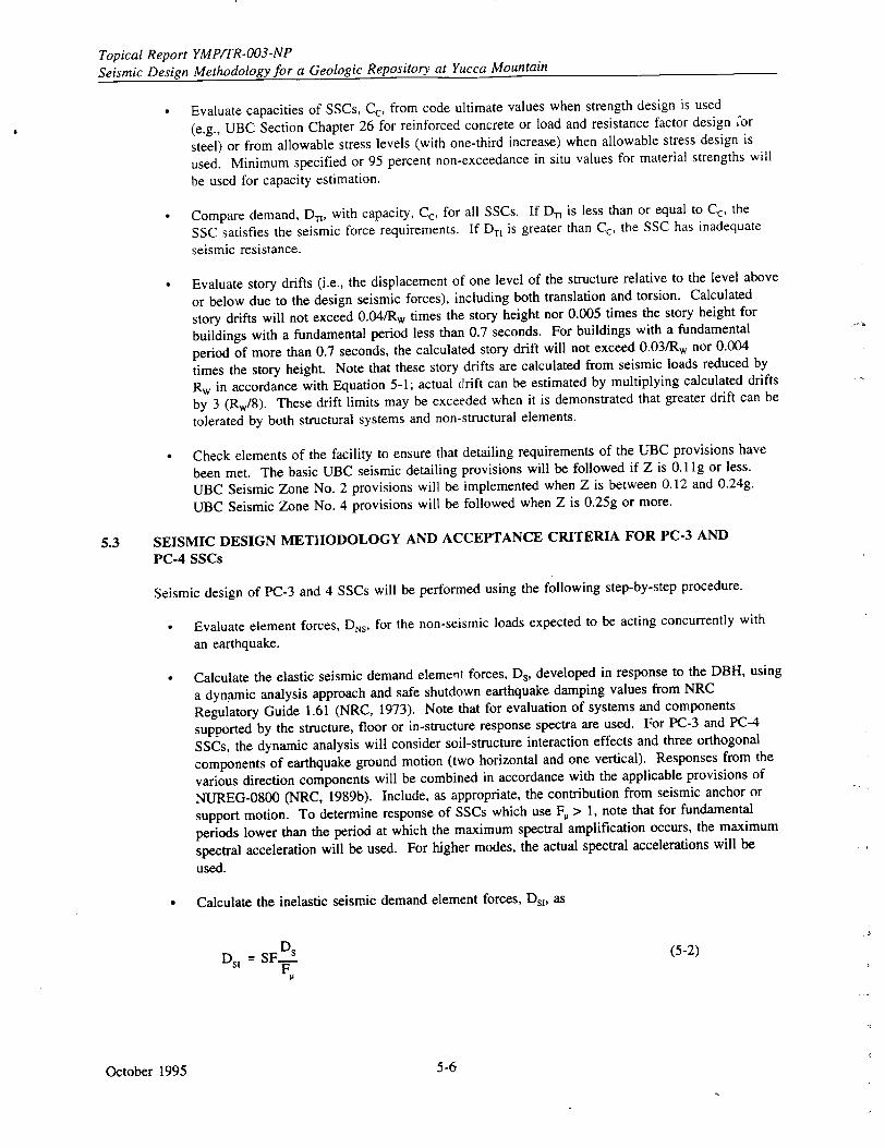
Topical Report YMP/TR-003-NP Seismic Design Methodology for a Geologic Repository at Yucca Mountain
Evaluate capacities of SSCs, Cc, from code ultimate values when strength design is used
(e.g., UBC Section Chapter 26 for reinforced concrete or load and resistance factor design for
steel) or from allowable stress levels (with one-third increase) when allowable stress design is
used. Minimum specified or 95 percent non-exceedance in situ values for material strengths will
be used for capacity estimation.
" Compare demand, D,, with capacity, Cc, for all SSCs. If D, is less than or equal to Cc, the
SSC satisfies the seismic force requirements. If Dt is greater than Cc, the SSC has inadequate
seismic resistance.
" Evaluate story drifts (i.e., the displacement of one level of the structure relative to the level above
or below due to the design seismic forces), including both translation and torsion. Calculated
story drifts will not exceed 0.04/R, times the story height nor 0.005 times the story height for
buildings with a fundamental period less than 0.7 seconds. For buildings with a fundamental
period of more than 0.7 seconds, the calculated story drift will not exceed 0.03/R, nor 0.004
times the story height. Note that these story drifts are calculated from seismic loads reduced by
R, in accordance with Equation 5-1; actual drift can be estimated by multiplying calculated drifts
by 3 (Rw/8). These drift limits may be exceeded when it is demonstrated that greater drift can be
tolerated by both structural systems and non-structural elements.
Check elements of the facility to ensure that detailing requirements of the UBC provisions have
been met. The basic UBC seismic detailing provisions will be followed if Z is 0.1 Ig or less.
UBC Seismic Zone No. 2 provisions will be implemented when Z is between 0.12 and 0.24g.
UBC Seismic Zone No. 4 provisions will be followed when Z is 0.25g or more.
5.3 SEISMIC DESIGN METHODOLOGY AND ACCEPTANCE CRITERIA FOR PC-3 AND
PC-4 SSCs
Seismic design of PC-3 and 4 SSCs will be performed using the following step-by-step procedure.
* Evaluate element forces, DNS, for the non-seismic loads expected to be acting concurrently with
an earthquake.
" Calculate the elastic seismic demand element forces, Ds, developed in response to the DBH, using
a dynamic analysis approach and safe shutdown earthquake damping values from NRC
Regulatory Guide 1.61 (NRC, 1973). Note that for evaluation of systems and components
supported by the structure, floor or in-structure response spectra are used. For PC-3 and PC-4
SSCs, the dynamic analysis will consider soil-structure interaction effects and three orthogonal
components of earthquake ground motion (two horizontal and one vertical). Responses from the
various direction components will be combined in accordance with the applicable provisions of
NUREG-0800 (NRC, 1989b). Include, as appropriate, the contribution from seismic anchor or
support motion. To determine response of SSCs which use F. > 1, note that for fundamental
periods lower than the period at which the maximum spectral amplification occurs, the maximum
spectral acceleration will be used. For higher modes, the actual spectral accelerations will be
used.
"* Calculate the inelastic seismic demand element forces, D,,, as
D5 1 =SF D s (5-2) _F.
October 1995 5-6
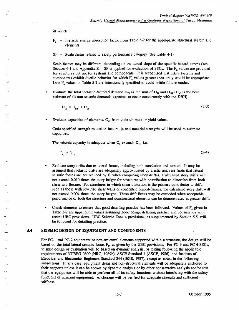
Topical Report YMPITR-003-NP Seismic Design Methodology for a Geologic Repository at Yucca Mountain
in which
FP = Inelastic energy absorption factor from Table 5-2 for the appropriate structural system and elements
SF = Scale factor related to safety performance category (See Table 4-1)
Scale factors may be different, depending on the actual slope of site-specific hazard curvf- (see Section 4-1 and Appendix B). SF is applied for evaluation of SSCs. The F. values are provided for structures but not for systems and components. It is recognized that many systems and components exhibit ductile behavior for which F, values greater than unity would be appropriate. Low F, values in Table 5-2 are intentionally specified to avoid brittle failure modes.
" Evaluate the total inelastic-factored demand D, as the sum of Ds, and DNs (Drs is the best estimate of all non-seismic demands expected to occur concurrently with the DBH).
DTI = DNS + Ds1 (5-3)
" Evaluate capacities of elements, Cc, from code ultimate or yield values.
Code-specified strength reduction factors, 4), and material strengths will be used to estimate capacities.
The seismic capacity is adequate when Cc exceeds Dn,, i.e.,
Cc >! D, (5-4)
Evaluate story drifts due to lateral forces, including both translation and torsion. It may be assumed that inelastic drifts are adequately approximated by elastic analyses (note that lateral seismic forces are not reduced by F. when computing story drifts). Calculated story drifts will not exceed 0.010 times the story height for structures with contribution to distortion from both shear and flexure. For structures in which shear distortion is the primary contributor to drift, such as those with low rise shear walls or concentric braced-frames, the calculated story drift will not exceed 0.004 times the story height. These drift limits may be exceeded when acceptable performance of both the structure and nonstructural elements can be demonstrated at greater drift.
Check elements to ensure that good detailing practice has been followed. Values of F, given in Table 5-2 are upper limit values assuming good design detailing practice and consistency with recent UBC provisions. UBC Seismic Zone 4 provisions, as supplemented by Section 5.5, will be followed for detailing practice.
5.4 SEISMIC DESIGN OF EQUIPMENT AND COMPONENTS
For PC-I and PC-2 equipment or non-structural elements supported within a structure, the design will be based on the total lateral seismic force, Fp, as given by the UBC provisions. For PC-3 and PC-4 SSCs, seismic design or evaluation will be based on dynamic analysis, or testing following the applicable requirements of NUREG-0800 (NRC, 1989b), ASCE Standard 4 (ASCE, 1986), and Institute of Electrical and Electronics Engineers Standard 344 (IEEE, 1987), except as noted in the following subsections. In any case, equipment items and non-structural elements will be adequately anchored to their supports unless it can be shown by dynamic analysis or by other conservative analysis and/or test that the equipment will be able to perform all of its safety functions without interfering with the safety functions of adjacent equipment. Anchorage will be verified for adequate strength and sufficient stiffness.
October 19955-7
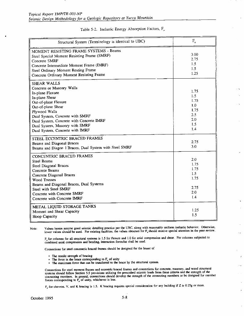
Topical Report YMP/TR-003-NP Seismic Design Methodology for a Geologic Repository at Yucca Mountain
Table 5-2. Inelastic Energy Absorption Factors, F,
Structural System (Terminology is identical to UBC) F
MOMENT RESISTING FRAME SYSTEMS - Beams
Steel Special Moment Resisting Frame (SMRF) 3.00
Concrete SMRF 2.75
Concrete Intermediate Moment Frame (IMRF) 1.5
Steel Ordinary Moment Resting Frame 1.5
Concrete Ordinary Moment Resisting Frame 1.25
SHEAR WALLS Concrete or Masonry Walls
In-plane Flexure 1.75
In-plane Shear 1.5
Out-of-plane Flexure 1.75
Out-of-plane Shear 1.0
Plywood Walls 1.75
Dual System, Concrete with SMRF 2.5
Dual System, Concrete with Concrete IMRF 2.0
Dual System, Masonry with SMRF 1.5
Dual System, Concrete with IMRF 1.4
STEEL ECCENTRIC BRACED FRAMES Beams and Diagonal Braces 2.75
Beams and Diagor 1 Braces, Dual System with Steel SMRF 3.0
CONCENTRIC BRACED FRAMES
Steel Beams 2.0
Steel Diagonal Braces 1.75
Concrete Beams 1.75
Concrete Diagonal Braces 1.5
Wood Trusses 1.75
Beams and Diagonal Braces, Dual Systems
Steel with Steel SMRF 2.75
Concrete with Concrete SMRF 2.0
Concrete with Concrete IMRF 1.4
METAL LIQUID STORAGE TANKS
Moment and Shear Capacity 1.25
Hoop Capacity 1.5
Note: Values herein assume good seismic detailing practice per the UBC, along with reasonably uniform inelastic behavior. Otherwise,
lower values should be used. For existing facilities, the values obtained for F. should receive special attention in the peer review.
F, for columns for all structural systems is 1.5 for flexure and 1.0 for axial compression and shear. For columns subjected to
combined axial compression and bending, interaction formulas shall be used.
Connections for steel concentric braced frames should be designed for the lesser of
"* The tensile strength of bracing "* The force in the brace corresponding to F. of unity "* The maximum force that can be transferred to the brace by the structural system.
Connections for steel moment frames and eccentric braced frames and connections for concrete, masonry, and wood structural
systems should follow Section 5.5 provisions utilizing the prescribed seismic loads from these criteria and the strength of the
connecting members. In general, connections should develop the strength of the connecting members or be designed for member
forces corresponding to F, of unity, whichever is less.
F. for chevron. V, and K bracing is 1.5. K bracing requires special consideration for any building if Z is 0.25g or more.
October 1995 5-8
Topical Report YMP/TR-003-NP Seismic Design Methodology for a Geologic Repository at Yucca Mountain
5.4.1 Evaluation by Analysis
Following the UBC provisions for PC-i and PC-2, parts of the structures, permanent non-structural components, and equipment supported by a structure and their anchorages and required bracing will be designed to resist seismic forces. Such elements will be designed to resist a total lateral seismic force, Fp, of
FP -- ZICP WP (5-5)
in which
Wp, = the weight of element or component Cp = a horizontal force factor as given by Table 23-P of the UBC for rigid elements, or determined
from the dynamic properties of the element and supporting structure for nonrigid elements (in the absence of detailed analysis, the value of C, for a nonrigid element will be taken as twice the value listed in UJBC Table 23-P, but need not exceed 2.0).
The lateral force determined using Equation 5-5 will be distributed in proportion to the mass distribution .of the element or component. Forces determined from Equation 5-5 will be used for the design or evaluation of elements or components and their connections and anchorage to the structure, and for members and connections that transfer the forces to the seismic-resisting systems. Forces will be applied in the horizontal direction that results in the most critical loadings for design and evaluation.
Note that the method proposed here takes one exception to the UBC provisions. For equipment located above grade, according to UBC, the value C, for non-rigid or flexibly supported items is twice the value for rigid and rigidly supported equipment. However, for equipment located at or below grade, the value C, for non-rigid or flexibly supported items is the same as the value for rigid and rigidly supported equipment. But in the method proposed here, for equipment located at or below grade, the value C, for non-rigid or flexibly supported items (except for piping, ducting or conduit systems made of ductile materials and connections) is specified to be twice the value for rigid and rigidly supported equipment.
For PC-3 and PC-4 subsystems and components, support excitation will be represented by means of floor response spectra (also commonly called in-structure response spectra). Floor response spectra will be developed accounting for the expected response level of the supporting structure even though limited inelastic behavior is permitted in the design of the structure. It is important to account for uncertainty in the properties of the equipment, supporting structure, and supporting media when using in-structure spectra that have narrow peaks. For this purpose, the peak broadening or peak shifting techniques outlined in NRC regulatory guides and standard review plans should be used (supplemented by ASCE Standard 4, 1986).
Equipment or distribution systems that are supported at multiple locations throughout a structure could have different floor spectra for each support point. In such a case, it is considered acceptable to use a single envelope spectrum of all locations as the input to all supports to obtain the inertial loads. Alternatively, available analytical techniques for using different spectra at each support location or for using different input time histories at each different support will be used.
For multiply-supported components with different seismic inputs, support displacements will be obtained either from the structural response calculations of the supporting structure or from spectral displacement determined from the floor response spectra. The effect of relative seismic anchor displacements will be obtained by using the worst combination of peak displacements or by proper representation of the relative phasing characteristics associated with different support inputs.
October 19955-9
Topical Report YMP/TR-003-NP Seismic Design Methodology for a Geologic Repository at Yucca Mountain
In performing an analysis of systems with multiple supports, the response from the inertial loads will be
combined with the responses obtained from the seismic anchor displacement analysis of the system by
the square root of the sum of the square rule, (RI,,i,)2 + (RsAM)2J
where R = response parameter of interest, Rita = inertial component of the response, and
RsAM = response due to seismic anchor or support movement.
5.4.2 Evaluation by Testing
Seismic evaluations of PC-3 and PC-4 equipment and components by testing will be performed in
accordance with the applicable provisions of NUREG-0800 (NRC, 1989b), as supplemented by IEEE
344 (IEEE, 1987), ASCE Standard 4 (ASCE, 1986), and the requirements of this section. Input or
demand excitation for the tested equipment will be based on the seismic hazard curves at the specified
annual probability (PH) for the safety performance category of the equipment (operating basis earthquake
provisions do not apply). When equipment is qualified by shake table testing, the DBH input to the
equipment is defined by an elastic computed required response spectrum that is obtained by enveloping
and smoothing (filling in valleys) the in-structure spectra computed at the equipment supports by linear elastic analyses.
To meet the target safety performance goals established for the equipment, the required response
spectrum (RRS) must exceed 1.4 SF times the in-structure spectra (see Appendix B, Section B.3). For PC-1 and PC-2 SSCs this leads to a minimum RRS of 0.93 times the in-structure spectra. However, to
introduce additional conservatism, PC-1 and PC-2 SSCs in the repository, when qualified by testing, will
use an RRS equal to 1.1 times the in-structure spectra (as required by the NRC for Seismic Category I
equipment). For PC-3 and PC-4 SSCs the factors are 1.4 and 1.75, respectively; these factors are
significantly more conservative than the NRC's present requirements (see also Appendix C).
The test response spectrum of test table motions will envelop the required response spectrum.
5.4.3 Seismic Evaluation of Anchorage and Supports
Adequate strength of equipment anchorage requires consideration of tension, shear, and shear-tension interaction load conditions. The strength of cast-iri-place anchor bolts and undercut type expansion
anchors will be based on UBC provisions for PC-I and PC-2 SSCs and on American Concrete Institute
349 (ACI, 1985) provisions for PC-3 and PC-4 SSCs. For design by ACI 349 provisions, it is required
that the concrete pullout failure capacity be greater than the steel cast-in-place bolt tensile strength to ensure ductile behavior.
The strength of expansion anchor bolts will generally be based on design allowable strength values available from standard manufacturers' recommendations or other published test results. Design-allowable strength values will include a factor of safety of 4 on the mean ultimate capacity of the anchorage. For strength considerations of welded anchorage, American Institute of Steel Construction (AISC) allowable values multiplied by 1.7 will be used. Where shear in the member governs the connection strength, capacity will be determined by multiplying the AISC allowable shear stress by 1.4.
Stiffness of equipment anchorage will also be considered. Flexibility of base anchorage can be caused
by the bending of anchorage components or equipment sheet metal. Excessive eccentricity in the load
path between the equipment item and the anchor is a major cause of base anchorage flexibility. Equipment base flexibility can allow excessive equipment movement and reduce its natural frequency, possibly increasing dynamic response. In addition, flexibility can lead to high stresses in anchorage components and failure of the anchorage or equipment sheet metal. These factors will be considered in designing the anchors.
October 1995 5-10
Topical Report YMP/TR-003-NP
Seismic Design Methodology for a .Geologic Repository at Yucca Mountain
5.5 SEISMIC DESIGN AND DETAILING FOR DUCTILITY AND RUGGEDNESS
This section describes general design considerations and recommended seismic design practices that will be followed for achieving a well-designed earthquake-resistant repository facility. Considerations for good earthquake resistance of structures, equipment, and distribution systems include configuration symmetry, continuous and redundant load paths, detailing for ductile behavior, tieing systems together, and influence of nonstructural components. Each is briefly discussed below. While the following discussion is concerned primarily with buildings, the principles are applicable to enhancing the earthquake resistance of equipment, distribution systems, or other components.
5.5.1 Configuration Symmetry
Structure configuration is very important to earthquake response. Irregular structures have experienced greater damage during past earthquakes than uniform, symmetrical structures. This has been the case even with good design and construction; therefore structures with regular configurations will be encouraged. Irregularities such as large re-entrant corners create stress concentrations which produce high local forces. Other plan irregularities can result in substantial torsional response during an earthquake. These include irregular distribution of mass or vertical seismic resisting elements or differences in stiffness between portions of a diaphragm. These also include imbalance in strength and failure mechanisms even if elastic stiffnesses and masses are balanced in plan. Vertical irregularities can produce large local forces during an earthquake. These include large differences or eccentricities in stiffness or mass in adjacent levels or significant horizontal off-sets at one or more levels. These undesirable characteristics will be avoided in the design whenever possible. In addition, adjacent structures will be separated sufficiently so that they do not hammer one another during seismic response.
5.5.2 Continuous and Redundaat Load Paths
Earthquake excitation induces forces at all points within structures or equipment of significant mass. These forces may act in any direction. Structures are most vulnerable to damage from lateral seismic-induced forces, and prevention of damage requires a continuous load path (or paths) from regions of significant mass to the foundation or location of support. In implementing the performance goal-based seismic design method, it will be required that the designer follow seismic-induced forces through the structure (or equipment or distribution systems) into the ground, and ensure that every element and connection along the load path is adequate in strength and stiffness to maintain the integrity of the system. Redundancy of load paths is a highly desirable characteristic for earthquake-resistant design. When the primary element or system yields or fails, the lateral forces can be redistributed to a secondary system to prevent progressive failure. In a structural system without redundant components, every component must remain operative to preserve the integrity of the structure. As a good practice, redundancy will be incorporated into the seismic-resisting system, rather than relying on any system in which distress in any member or element may cause progressive or catastrophic collapse.
In some structures, the system carrying earthquake-induced loads may be separate from the system that carries gravity loads. Although the gravity load carrying systems are not needed for lateral resistance, they will deform with the rest of the structure as it deforms under lateral seismic loads. To ensure that it is adequately designed, the vertical load carrying system will be evaluated for compatibility with the deformations resulting from an earthquake. Similarly, gravity loads will be combined with earthquake lctads in the evaluation of the lateral force resisting system.
5.5.3 Detailing For Ductile Behavior
In general, in areas with very low probability of earthquake occurrence, it is uneconomical or impractical to design structures to remain within the elastic range of stress. Furthermore, it is highly desirable to design structures or equipment in a manner that avoids low ductility response and premature unexpected failure by assuring that the structure or equipment is able to dissipate the energy of the
October 19955-11
Topical Report YMPITR-003-NP Seismic Design Methodology for a Geologic Repository at Yucca Mountain
earthquake excitation without unacceptable damage. As a result, good seismic design practice requires
selection of an appropriate structural system with detailing to develop sufficient energy absorption
capacity to limit damage to permissible levels.
Structural steel is an inherently ductile material. Energy absorption capacity is achieved by designing
connections to avoid tearing or fracture and to ensure an adequate path for a load to travel across the
connection. Detailing for adequate stiffness and restraint of compression braces, outstanding legs of
members, compression flanges, etc., will be provided to avoid instability by buckling for relatively
slender steel members acting in compression. Furthermore, deflections will be limited to prevent overall
frame instability due to P-delta effects.
Less ductile materials, such as concrete and masonry, require steel reinforcement to provide the ductility
characteristics necessary to resist seismic forces. Concrete structures will, in general, be designed to
prevent concrete compressive failure, concrete shearing and diagonal tension failure, or loss of
reinforcing bond or anchorage. Compression failures in flexural members will be controlled by limiting
the amount of tensile reinforcement or by providing compression reinforcement and requiring
confinement by closely spaced transverse reinforcing of longitudinal reinforcing bars (e.g., spirals,
stirrup ties, or hoops and supplementary cross ties). Confinement increases the strain capacity and
compressive, shear, and bond strengths of concrete. Maximum confinement will-be provided near joints
and in column members. Failures of concrete in shear or diagonal tension will be controlled by
providing sufficient shear reinforcement, such as stirrups and inclined bars.
Anchorage failures are controlled by sufficient lapping of splices, mechanical connections, welded
connections, etc. Added reinforcement will be provided around openings and at corners where stress
concentrations might occur during earthquake motions. Masonry walls will be adequately reinforced
and anchor-, to floors and roofs.
In general, as part of good seismic detailing practice, steel and reinforced concrete members will be
proportioned such that they can behave in a ductile manner and provide sufficient strength so that low
ductility failure modes do not govern the overall seismic response. In this manner, sufficient energy
absorption capacity will be achieved so that earthquake motion does not produce excessive or
unacceptable damage.
5.5.4 Tieing Elements Together
One of the most important attributes of an earthquake-resistant structural system is that its load-carrying
elements are tied together to act as a unit. This attribute aids earthquake resistance and helps to resist
high winds, floods, explosions, progressive failure, and foundation settlement. The primary structural
systems will be interconnected. Beams and girders will be adequately tied to columns, and columns will
be adequately tied to footings. Concrete and masonry walls will be anchored to all floors and roofs for
out-of-plane lateral support. Diaphragms that distribute lateral loads to vertical resisting elements will
be adequately tied to these elements. Collector or drag bars will be provided to collect shear forces and
transmit them to the shear-resisting elements, such as shear walls or other bracing elements, that may
not be uniformly spaced around the diaphragm. Shear walls will be adequately tied to floor and roof
slabs and to footings, and individual footings will be adequately tied together when the foundation
media is capable of significant differential motion.
5.5.5 Influence of Nonstructural Components
For both evaluation of seismic response and for seismic detailing, the effects of nonstructural elements
of buildings or equipment will be considered. Elements such as partitions, filler walls, stairs, large bore
piping, and architectural facings can have a substantial influence on the magnitude and distribution of
earthquake-induced forces. Even though these elements are not part of the lateral force-resisting system,
they can stiffen that system and carry some lateral force. In addition, nonstructural elements attached to
October 1995 5-12
Topical Report YMPITR-003-NP Seismic Design Methodology for a Geologic Repository at Yucca Mountain
the structure will, in general, be designed in a manner that allows for seismic deformations of the structure without excessive damage. Damage to such items as distribution systems, equipment, glass, plaster, veneer, and partitions may constitute a hazard to personnel within or outside the facility and a major financial loss; such damage may also impair the function of the facility to the extent that hazardous operations cannot be shut down or confined. To minimize this type of damage, special care in detailing will be given either to isolate these elements or to accommodate structural movements.
5.6 SEISMIC INTERACTION CONSIDERATIONS
During an earthquake, it is possible for the seismic response of one SSC to affect the performance of other SSCs. This sequence of events is called seismic interaction. Seismic interactions that may have an adverse effect on PC-3 and PC-4 SSCs will be considered in seismic design and evaluation of repository facilities. Cases of seismic interaction that will be considered include
* Structural failing and falling * Proximity * Flexibility of attached lines and cables * Flooding or exposure to fluids from ruptured vessels and piping systems • Effects of seismically induced fires.
Structural failing and falling is generally prevented by single-failure seismic design criteria. An interaction problem arises where a higher category (such as PC-4) SSC (target) is in danger of being damaged due to the failure of overhead or adjacent lower category (sueh as PC-l, PC- 2, or PC-3) SSCs (sources) which have been designed for lesser seismic loads than the higher category SSC (target). Lower category items interacting with higher category items or barriers protecting the target items will be designed to prevent adverse seismic interaction. If there is potential interaction, the source (or any barrier that would prevent adverse interaction) will be designed to maintain structural integrity when subjected to the earthquake ground motion associated with the P, of the target SSC performance category, even though the source SSC may belong to a lower performance category and will continue to remain in its own category. For example, say a PC-2 building (the source) may potentially collapse onto a PC-3 system (the target) it houses-and cause unacceptable leakage to the PC-3 system during an earthquake. The seismic interaction requirement is that the PC-2 building must not "collapse" more frequently than PC-3 performanze goal (i.e., O1y4 per year, see Table 4-1). Noting that PC-1 acceptance criteria are sufficient to prevent "collapse" (PC-2 criteria ensure operability, PC-3 and PC-4 criteria ensures very small crack size), the additional interaction-related design requirement for the PC-2 building will be that it must satisfy PC-1 acceptance criteria when subjected to an earthquake ground motion associated with the PH of the PC-3 system (i.e., 5 x 10⁻⁴ per year, see Table 4-1).
Impact between SSCs in close proximity because of relative motion during earthquake response is another form of interaction that will be considered for design and evaluation of PC-3 and PC-4 SSCs. If such impact could cause damage or failure, the design approach will combine sufficient separation distance to prevent impact, with adequate anchorage, bracing, or other means to prevent large deflections. Note that even if there is impact between adjacent structures or equipment, there may not be potential for any significant damage, in which case the seismic interaction would not result in design measures being implemented. For example, a 1-inch diameter pipe cannot damage a 12-inch diameter pipe regardless of the separation distance. The designer will justify and document these cases.
Design measures for preventing adverse performance from structural failing and falling and proximity seismic interaction modes include strength and stiffness, separation distance, and barriers. Sources may be designed to be strong enough to prevent falling or stiff enough to prevent large displacements such that adverse interaction does not occur. Maintaining function of the source item under this increased seismic design requirement is not necessary. Source and targets can be physically separated sufficient distance such that, under seismic response displacements expected for target design criteria earthquake
October 19955-13
Topical Report YMP/TR-003-NP Seismic Design Methodology for a Geologic Repository at Yucca Mountain
excitation, adverse interaction will not occur. Barriers can be designed to protect the target from source
falling or source motions.
Another form of seismic interaction occurs where distribution lines such as piping, tubing, conduit, or
cables that are connected to an item that is important to safety or waste isolation have insufficient
flexibility to accommodate relative movement between the important item and adjacent structures or
equipment to which the distribution line is anchored. Sufficient flexibility of such lines will be provided
from the important item to the first support on nearby structures or equipment.
Other forms of seismic interaction result if vessels or piping systems rupture due to earthquake
excitation and cause fires or flooding which could adversely affect performance of nearby important or
critical SSCs. In this case, such vessels or piping systems must continue to perform their function of
containing fluids or combustibles.
October 1995 5-14
Topical Report YMPITR-003-NP Seismic Design Methodology for a Geologic Repository at Yucca Mountain
6.0 SEISMIC DESIGN OF UNDERGROUND OPENINGS AND GROUND SUPPORT SYSTEMS FOR VIBRATORY GROUND MOTION
The underground openings in the waste repository consist of three major categories: shafts; ramps; and drifts, rooms, and alcoves. Their primary difference is in orientation: shafts are vertical; drifts, rooms, and alcoves are horizontal; and ramps are inclined. Shafts, ramps, and main drifts provide access to and egress from the repository storage areas. Emplacement drifts are intended for waste storage. Rooms
and alcoves are for conducting the site characterization testing activities or provide space for specific "facilities or functions. Intersectioh~s of any of these components are areas of concern for design because wider openings can result in higher rock loads to the ground support system.
The ground support system installed in an underground structure generally includes rockbolts, shotcrete, wire mesh, steel sets, and cast-in-place concrete liners. These can be used individually or in
- -. combination. For discussion purposes, these ground support components are grouped into two categories, concrete support and steel support, although other materials may be specified for corrosion protection or specific functions. When both underground openings and ground support systems (UOGSS) together are mentioned in the following subsection, they are combined and termed as underground structures.
Design criteria and procedures in UOGSS are governed by recognized practices. In general, underground openings are much safer than surface structures for a given level of shaking (Dowding and Rozen, 1978), and this safety increases exponentially down to a depth of 500 m (Wang, 1985). Sharma and Judd (1991) observed that only 94 cases of underground damage have been reported "while literally thousands of surface structures have been damaged during earthquakes." Section 2.1.3.2 describes the regulatory requirement for the performance of underground facilities with implicit consideration of seismic events. In this sec-ion, a rational seismic design methodology is presented for UOGSS that is intended to satisfy this requirement and to be consistent with the Department of Energy's (DOE's) safety performance goal-based seismic design methodology (described in Sections 1, 3, and 4 of this report).
6.1 SAFETY PERFORMANCE REQUIREMENTS
The underground facilities in the waste repository must meet the safety requirements set by the technical directives issued by the Nuclear Regulatory Commission (NRC) and other government agencies concerned with worker health and safety and environmental protection, such as the Mine Safety and Health Administration and the Occupational Safety and Health Administration.
The safety performance requirements for the UOGSS under seismic loading are related to stability and material performance. The NRC's regulations in 10 CFR Part 60 address rock stability requirements for the repository (See Section 2). Requirements for non-radiological worker safety are given in Paragraphs 60.131 and 60.133. Requirements for maintaining the option for retrievability of the waste are described in Paragraph 60.111 (b).
For accommodating possible damage from repetitive seismic loading, a program of inspection, maintenance, and rehabilitation of underground structures is planned for all underground structures and will be maintained during the preclosure period. This program of inspection and remedial action (maintenance or rehabilitation) would be both routine and triggered after a modest to significant earthquake. The criteria for triggering inspections have not yet been established; they will be established as part of the detailed seismic design and included in the operational plan for the repository. The inspection, maintenance, and rehabilitation program will ensure the performance of underground openings to mitigate low-probability/low-consequence events, such as repetitive seismic loading and unexpected rock deformation.
October 19956-1.
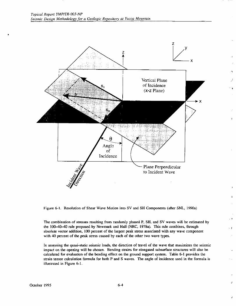
Topical Report YMP/TR-003-NP
Seismic Design Methodology for a Geologic Repository at Yucca Mountain
Figure 6-1. Resolution of Shear Wave Motion into SV and SH Components (after SNL, 1990a)
The combination of stresses resulting from randomly phased P, SH, and SV waves will be estimated by the 100-40-40 rule proposed by Newmark and Hall (NRC, 1978a). This rule combines, through absolute vector addition, 100 percent of the largest peak stress associated with any wave component with 40 percent of the peak stress caused by each of the other two wave types.
In assessing the quasi-static seismic loads, the direction of travel of the wave that maximizes the seismic impact on the opening will be chosen. Bending strains for elongated subsurface structures will also be calculated for evaluation of the bending effect on the ground support system. Table 6-1 provides the strain tensor calculation formula for both P and S waves. The angle of incidence used in the formula is illustrated in Figure 6-1.
October 1995 6-4
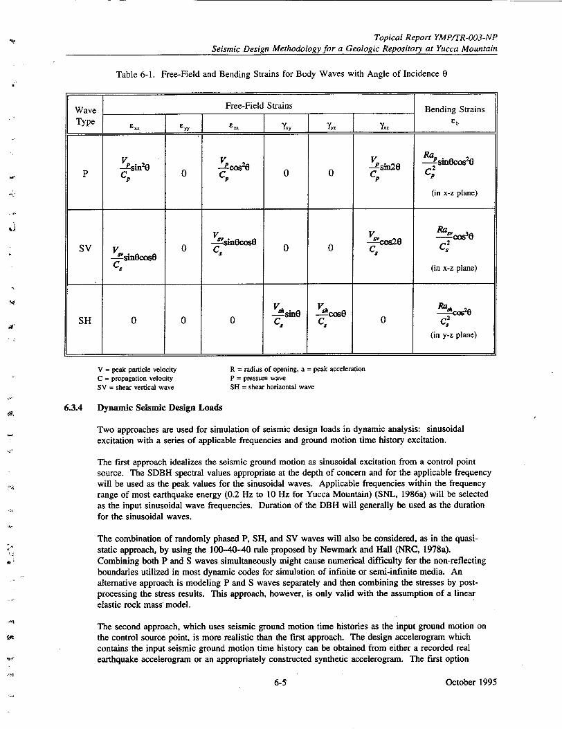
Topical Report YMPITR-003-NP
Seismic Design Methodology for a Geologic Repository at Yucca Mountain
Table 6-1. Free-Field and Bending Strains for Body Waves with Angle of Incidence 0
V = peak particle velocity C = propagation velocity SV = shear vertical wave
R = radiis of opening, a = peak acceleration P = pressure wave SH = shear horizontal wave
6.3.4 Dynamic Seismic Design Loads
Two approaches are used for simulation of seismic design loads in dynamic analysis: sinusoidal excitation with a series of applicable frequencies and ground motion time history excitation.
The first approach idealizes the seismic ground motion as sinusoidal excitation from a control point source. The SDBH spectral values appropriate at the depth of concern and for the applicable frequency will be used as the peak values for the sinusoidal waves. Applicable frequencies within the frequency range of most earthquake energy (0.2 Hz to 10 Hz for Yucca Mountain) (SNL, 1986a) will be selected
as the input sinusoidal wave frequencies. Duration of the DBH will generally be used as the duration for the sinusoidal waves.
The combination of randomly phased P, SH, and SV waves will also be considered, as in the quasistatic approach, by using the 100-40-40 rule proposed by Newmark and Hall (NRC, 1978a). Combining both P and S waves simultaneously might cause numerical difficulty for the non-reflecting boundaries utilized in most dynamic codes for simulation of infinite or semi-infinite media. An alternative approach is modeling P and S waves separately and then combining the stresses by postprocessing the stress results. This approach, however, is only valid with the assumption of a linear elastic rock mass model.
The second approach, which uses seismic ground motion time histories as the input ground motion on the control source point, is more realistic than the first approach. The design accelerogram which contains the input seismic ground motion time history can be obtained from either a recorded real earthquake accelerogram or an appropriately constructed synthetic accelerogram. The first option
October 1995
Wave Free-Field Strains Bending Strains Type XX •yy •=Y~y 7yy 7.• Eb
VP nn20) Vr2• Ra sin0cos2o
P CP 0 Cv 0 C C;
(in x-z plane)
V v R sv V 0,si Oeo 0 Co 0 0 C e C'2
"-sin0cosO 00 C C. (in x-z plane)
VA sine !ý!Cos0 R!ac2 e SH 0 00 C, C, 0 C
(in y-z plane)
6-5
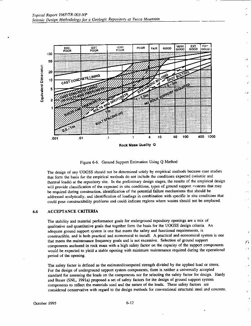
Topical Report YMP/TR-003-NP Seismic Design Methodology for a Geologic Repository at Yucca Mountain
100
50
20
10
5
2
1
I.
.001
Rock Mass Quality 0
Figure 6-6. Ground Support Estimation Using Q Method
The design of any UOGSS should not be determined solely by empirical methods because case studies
that form the basis for the empirical methods do not include the conditions expected (seismic and
thermal loads) at the repository site. In the preliminary design stages, the results of the empirical design
will provide classification of the expected in situ conditions, types of ground support systems that may
be required during construction, identification of the potential failure mechanisms that should be
addressed analytically, and identification of loadings in combination with specific in situ conditions that
could pose constructibility problems and could indicate regions where wastes should not be emplaced.
6.6 ACCEPTANCE CRITERIA
The stability and material performance goals for underground repository openings are a mix of
qualitative and quantitative goals that together form the basis for the UOGSS design criteria. An
adequate ground support system is one that meets the safety and functional requirements, is
constructible, and is both practical and economical to install. A practical and economical system is one
that meets the maintenance frequency goals and is not excessive. Selection of ground support
components anchored in rock mass with a high safety factor on the capacity of the support components
would be expected to yield a stable opening with minimum maintenance required during the operational period of the opening.
The safety factor is defined as the estimated/computed strength divided by the applied load or stress.
For the design of underground support system components, there is neither a universally accepted
standard for assessing the loads on the components nor for selecting the safety factor for design. Hardy
and Bauer (SNL, 1991a) proposed a set of safety factors for the design of ground support system
components to reflect the materials used and the nature of the loads. These safety factors are
considered conservative with regard to the design methods for conventional structural steel and concrete.
October 1995
0" u,I
6- 12
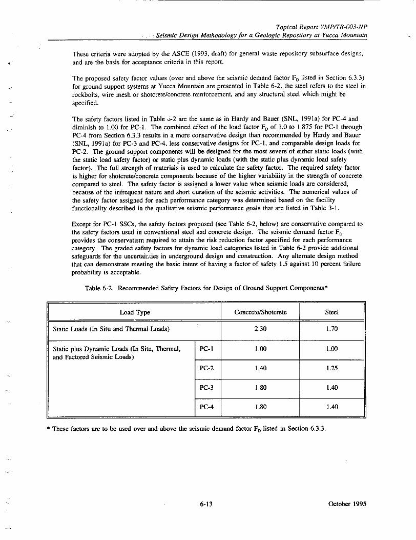
Topical Report YMP/TR-003-NP Seismic Design Methodology for a Geologic Repository at Yucca Mountain
These criteria were adopted by the ASCE (1993, draft) for general waste repository subsurface designs, and are the basis for acceptance criteria in this report.
The proposed safety factor values (over and above the seismic demand factor F, listed in Section 6.3.3) for ground support systems at Yucca Mountain are presented in Table 6-2; the steel refers to the steel in rockbolts, wire mesh or shotcrete/concrete reinforcement, and any structural steel which might be specified.
The safety factors listed in Table 0-2 are the same as in Hardy and Bauer (SNL, 1991 a) for PC-4 and diminish to 1.00 for PC-i. The combined effect of the load factor FD of 1.0 to 1.875 for PC-1 through PC-4 from Section 6.3.3 results in a more conservative design than recommended by Hardy and Bauer (SNL, 1991a) for PC-3 and PC-4, less conservative designs for PC-I, and comparable design loads for PC-2. The ground support components will be designed for the most severe of either static loads (with the static load safety factor) or static plus dynamic loads (with the static plus dynamic load safety factor). The full strength of materials is used to calculate the safety factor. The required safety factor is higher for shotcrete/concrete components because of the higher variability in the strength of concrete compared to steel. The safety factor is assigned a lower value when seismic loads are considered, because of the infrequent nature and short curation of the seismic activities. The numerical values of the safety factor assigned for each performance category was determined based on the facility functionality described in the qualitative seismic performance goals that are listed in Table 3-1.
Except for PC-1 SSCs, the safety factors proposed (see Table 6-2, below) are conservative compared to the safety factors used in conventional steel and concrete design. The seismic demand factor FD provides the conservatism required to attain the risk reduction factor specified for each performance category. The graded safety factors for dynamic load categories listed in Table 6-2 provide additional safeguards for the uncertair.ties in underground design and construction. Any alternate design method that can demonstrate meeting the basic intent of having a factor of safety 1.5 against 10 percent failure probability is acceptable.
Table 6-2. Recommended Safety Factors for Design of Ground Support Components*
Load Type Concrete/Shotcrete Steel
Static Loads (In Situ and Thermal Loads) 2.30 1.70
Static plus Dynamic Loads (In Situ, Thermal, PC-1 1.00 1.00 and Factored Seismic Loads)
PC-2 1.40 1.25
PC-3 1.80 1.40
PC-4 1.80 1.40
* These factors are to be used over and above the seismic demand factor FD listed in Section 6.3.3.
October 19956-13

Topical Report YMP/TR-003-NP Seismic Design Methodology for a Geologic Repository at Yucca Mountain
INTENTIONALLY LEFT BLANK
October 1995 6-14
Topical Report YMP/TR-003-NP Seismic Design Methodology for a Geologic Repository at Yucca Mountain
7.0 SEISMIC DESIGN OF OTHER UNDERGROUND STRUCTURES, SYSTEMS, AND COMPONENTS FOR VIBRATORY GROUND MOTION
In addition to underground openings and ground support systems, the subsurface repository areas will have other structures, systems, and components (SSCs) that will need to be designed to withstand seismic ground motion. Such SSCs are those associated with ventilation systems; waste package transportation systems; electrical cable tray and conduit systems; instrumentation, monitoring, and alarm systems; shielding doors; and waste packages. With the exception of the waste package and transportation systems, these SSCs will be located in the underground openings and will either be anchored directly to the rock or supported from frame-type structures anchored to the rock. The waste package is not included in this section, but is discussed separately in Section 8.
7.1 PERFORMANCE REQUIREMENTS
The systems associated with underground items discussed in this section are, in general, similar to the systems in the repository surface facilities and some of them are extensions of the surface systems. Examples are the cask handling and transportation system, ventilation system, cable tray system, and radiation monitoring system. The performance requirements defined in Section 5.4 for the equipment in the repository surface facilities are therefore applicable to the underground SSCs discussed in this section.
7.2 DESIGN CRITERIA AND ANALYSIS CONSIDERATIONS
The seismic adequacy of these SSCs, like the equipment and components in the surface facilities, will be ensured either by analytical evaluation or by shake table testing. The design criteria and analysis considerations are, in general, similar to those for the surface systems. Sources for the non-seismic demands may be different for the surface and subsurface subsystems (e.g., thermal effects of the emplaced waste on the SSCs in the emplacement drifts).
7.3 DESIGN LOADS AND RESPONSES DUE TO SEISMIC GROUND MOTION
7.3.1 Performance Category 3 and 4 SSCs
Determination of design loads and response for PC-3 and PC-4 SSCs due to seismic ground motion are presented separately for two categories: SSCs anchored directly to the rock and SSCs supported from structures anchored to the rock.
For SSCs anchored to the rock, design loads and responses will be determined using the approach for the surface subsystems described in Section 5.4.3 and based on the ground motion spectra applicable to the anchor location (see Section 6.3).
For SSCs that are supported from the structures, the design loads and responses will be determined in accordance with Section 5.4.
October 19957-1-
Topical Report YMP/TR-003-NP Seismic Design Methodology for a Geologic Repository at Yucca Mountain
7.3.2 Performance Category 1 and 2 SSCs
For PC-I and PC-2 SSCs, the design loads shall be based on the total lateral force, Fp, as given by the Uniform Building Code (UBC) provisions. The peak ground acceleration required in the equation for calculating Fp will correspond to the ground motion applicable at the anchor location or at the base location of the supporting structure (see Section 6.3.1). The lateral force, Fp, shall be distributed in proportion to the mass distribution of the element or component and shall be used for the design or evaluation of its connections and anchorage to rock. Forces shall be applied in the horizontal direction that results in the most critical loadings for design and evaluation. Following the UBC procedures, the vertical component of the seismic load is accommodated in the load factor for the design loads.
7.4 OTHER LOAD CONSIDERATIONS
In addition to the seismic load described above, thermal effects, excavation-induced loads, effects of material creep (if any), and the effects of humidity changes shall be considered. In underground openings, the thermally induced stresses are considered static in the analytical evaluation.
7.5 ACCEPTANCE CRITERIA
The acceptance criteria applicable to the equipment and components in the repository surface facilities (see Section 5.4) are also applicable for the underground SSCs.
October 1995 7-2
Topical Report YMPITR-003-NP Seismic Design Methodology for a Geologic Repository at Yucca Mountain
8.0 SEISMIC DESIGN OF THE WASTE PACKAGE
The waste package is discussed separately because of its unique nature. The waste package is unique among repository SSCs because of its critical safety functions, postclosure performance requirements, and the requirement to perform safety functions both at the repository surface and subsurface. The waste package performs a key role in substantially complete containment, waste isolation, criticality control, and waste retrievability. Following is a description of the waste package as currently planned, its performance requirements, and seismic design considerations. Although the objective of this topical report is to address preclosure seismnic design, a discussion of the postclosure performance objectives of the waste package is also provided. Development of the waste package is in the preliminary design phase, but the design has not yet been finalized; therefore, the information discussed here is preliminary.
The waste package consists of the waste form, containers, shielding, packing, and absorbent materials, if any, surrounding an individual waste container. There are three waste package design configurations currently under consideration. These configurations accommodate the three varieties of waste forms that will be placed inside the waste packages and emplaced in the repository. The three proposed waste package configurations are
"* Spent fuel contained in a multi-purpose canister, placed inside outer containment barriers "* Uncanistered spent fuel supported by basket members, placed inside outer containment barriers * Vitrified high-level defense waste, placed inside outer containment barriers.
The majority of waste to be emplaced in the repository will be spent fuel placed in the multi-purposecanister. Vitrified high-level defense waste is expected to constitute approximately 10 percent of the waste. The remaining waste will be uncanistered spent fuel from utility sites that are unable to use the multi-purpose canister.
The current waste package conceptual design configurations are not self-shielding. Worker radiological protection during emplacement will be accomplished by a shielded transporter and remote handling. Radiological protection during the caretaker phase will be accomplished by restricting access to the emplacement drifts. During the postclosure phase, worker radiological protection will not be an issue because of the absence of workers in the repository.
Horizontal, in-drift emplacement is the current design assumption for waste package emplacement. This assumption follows the adoption of the multi-purpose canister-based waste package configuration as the primary waste package under consideration. The large, high thermal output multi-purpose canister is not well suited to borehole emplacement.
The preferred system for supporting the waste package in the repository has not been determined. Unlike most underground SSCs, the waste package may not be anchored directly to the rock or supported from frame-type structures anchored to the rock. Two alternative methods are being considered:
"* Support the waste package by cradling it on a pedestal. "* Support the waste package by a placing it on a waste emplacement cart mounted on rails.
October 19958-1.
Topical Report YMP/TR-003-NP Seismic Design Methodology for a Geologic Repository at Yucca Mountain
8.1 Waste Package Performance Requirements
The waste package is unique because of the multiple safety functions it serves. These safety functions are performed during emplacement, during the caretaker phase, and during postclosure. The key performance requirements for the waste package are
• Substantially complete containment (postclosure) * Criticality control (preclosure and postclosure) * Waste isolation (postclosure) • Retrievability (preclosure).
The waste package is required to provide substantially complete containment of the waste for 300 to 1,000 years after permanent closure. The current performance goal is to achieve mean waste package lifetimes well in excess of 1,000 years. The waste package configurations under consideration utilize robust, multiple containment barriers to achieve the waste containment performance objective.
Criticality control must be provided throughout the emplacement, containment, and waste isolation periods, beginning with loading of the waste into the waste package at the repository surface. The waste package will be required to provide this safety function for the spent nuclear fuel and defense high-level waste. The waste package will be designed to meet this performance requirement using the following methods.
• The multi-purpose canister internals will maintain waste in a geometry that is not favorable to criticality.
* The u :anistered spent fuel supporting structure will maintain the waste in a geometry that is not favorable to criticality.
• The vitrified waste form will maintain high-level defense waste in a geometry that is not favorable to criticality.
* Neutron absorbing materials will be incorporated into the spent fuel waste package internals.
"* Multiple containment barriers will prevent the presence of a moderator.
"* Credit will be taken for a portion of the reduced reactivity of the fuel due to burnup.
The current strategy for criticality control emphasizes the role of burnup credit for long-term (postclosure) criticality control.
The waste package is required to contribute to the performance of the engineered barrier system and repository such that the long-term waste isolation performance requirement is accomplished. Each of the waste package concepts under consideration are robust waste package designs which use multiple containment barriers. The use of multiple containment barriers is consistent with the well-accepted defense-in-depth approach. The multiple containment barriers will also serve to distribute waste package breaches over time, thereby enhancing compliance with the waste isolation phase's performance requirement for the gradual release of radionuclides. The waste package will contribute to the performance of the engineered barrier system such that following the 1,000-year substantially complete containment period, the radionuclide release rate will be less than or equal to 1 part in 100,000 per year of inventory at 1,000 years.
The repository will be designed to allow the waste to be retrieved for a period of up to 100 years after initial emplacement. The waste package will provide waste containment during the caretaker phase to meet this performance requirement.
October 1995 8-2-
Topical Report YMP/TR-003-NP Seismic Design Methodology for a Geologic Repository at Yucca Mountain
8.2 Seismic Design Considerations
The seismic design methodology presented in Section 3 is applicable to the waste package. However, seismic design of the waste package is discussed separately because of the key functions it plays and because it will perform safety functions both in the surface facility and underground. While at the surface, the waste package will be subject to the above ground seismic loading conditions and will meet the seismic design criteria described in Section 5. While in the subsurface facility, the waste package will be subject to the underground seismic loading conditions and will meet the seismic design criteria
described in Section 7. The waste package will likely be classified as a PC-4 component because of its key role in containing waste, isolating waste, retrieving waste, controlling criticality, and other design requirements. The waste package will be designed to maintain waste containment during on-site transportation, emplacement, and retrieval. Seismic design loading considerations contemplated for the waste package include the following surface and subsurface situations and conditions.
"* Rock fall onto the waste package during or after emplacement in the repository
"* Overturning of the waste package from the emplacement support in the repository or while being handled in the surface facilities
0 Integrity of the waste package internals (vitrified waste form, multi-purpose canister, or uncanistered fuel basket) to maintain waste geometry.
Seismically induced drop scenarios for waste package handling situations in the surface and subsurface facilities.
* Seismically induced shaking while in the surface and subsurface facilities.
Current conceptual design configurations call for a robust waste package using multiple containment barriers. The waste package will be designed for appropriate combinations of seismic and non-seismic (accident and normal) loads. Non-seismic loading conditions contemplated for the waste package include
* Emplaced loads
- Spent nuclear fuel and high-level waste loads - Differential thermal stresses - Residual thermal stresses - Internal structural loads - Imposed loads such as rock fall and backfill loads - Repository operational loads.
" Transportation loads
- Spent nuclear fuel and high-level waste loads - Differential thermal stresses - Internal structural loads - Handling accidents (slap down) - Transporter induced loads.
" Hot cell loads
- Handling - Waste package loading.
October 19958-3r
Topical Report YMP/TR-003-NP
Seismic Design Methodology for a Geologic Repository at Yucca Mountain
The waste package internals play a key safety role because they are required to maintain waste geometry
for criticality control. For the three waste package configurations under consideration, the waste
package internals are the multi-purpose canister with its basket structure for supporting spent fuel, the
uncanistered spent fuel supporting basket structure, and the vitrified high-level defense waste form. Of
the three waste package configurations under consideration, the multi-purpose canister-based concept is
in the most advanced state of development.
Information on the structural design criteria for the multi-purpose canister is presented here because this
provides an indication of the robust nature of the waste package internals. In particular, the
transportation loading requirements from 10 CFR Part 71 dictate that the multi-purpose canister will be
quite robust. The multi-purpose canister structural design criteria include the following requirements.
* The multi-purpose canister shall maintain the required geometric spacing of the spent nuclear fuel
assemblies to maintain a subcritical array configuration for all conditions as specified in 10 CFR
Part 71 (transportation) and 10 CFR Part 72 (storage).
• The multi-purpose canister shall be designed for the loading combinations, stress limits, and other
structural criteria contained in Nuclear RegLlatory Commission Regulatory Guides 7.6 and 7.8
(NRC, 1978b and NRC, 1989a).
• The multi-purpose canister spent nuclear fuel basket shall not yield or buckle under the loading
conditions specified in 10 CFR Parts 71 and 72.
• The multi-purpose canister minimum service life shall be 100 years.
October 1995 8-4
Topical Report YMPITR-003-NP Seismic Design Methodology for a Geologic Repository at Yucca Mountain
9.0 SEISMIC SAFETY DESIGN OF REPOSITORY STRUCTURES, SYSTEMS, AND COMPONENTS FOR FAULT DISPLACEMENT
9.1 INTRODUCTION
This section describes the methods, procedures and criteria that the Department of Energy (DOE) intends to use to provide reasonable assurance that structures, systems, and components (SSCs) important to safety will meet the pertinent 10 CFR Part 60 preclosure safety performance objectives with respect to fault displacements. Three approaches are available: fault avoidance, geotechnical engineering isolation techniques, and structural engineering design to increase structural ductility or to provide for structural modularization. The choice of approaches to be implemented for a particular SSC depends on the intended function of the SSC, its characteristics, and the geotechnical characteristics of the materials on which it is positioned.
In establishing the seismic safety design criteria for the Yucca Mountain Geologic Repository Operations Area (GROA) described in this section, the DOE intends to follow and implement the guidance provided in the Nuclear Regulator, Commission (NRC) Staff Technical Position on Consideration of Fault Displacement Hazards in Geologic Repository Design, NUREG-1494 (NRC, 1994a). The Staff Technical Position recommends that Type I faults within the GROA be avoided when reasonably achievable, but recognizes that fault avoidance may not be possible for all SSCs, especially those that are spatially extended. Thus, the primary seismic safety design criterion for fault displacement will be fault avoidance to the extent achievable by facility layout and placement of SSCs important to safety (i.e., PC-3 and PC-4 SSCs, see Section 3.). When the fault avoidance criterion cannot reasonably be achieved, geotechnical engineering and/or structural engineering design criteria or repair and rehabilitation actions will be provided to reasonably assure that preclosure seismic safety performance goals are met.
9.2 BACKGROUND
9.2.1 Experience in Design of Surface SSCs to Accommodate Fault Displacement
The specific issue of whether a nuclear facility can safely accommodate fault offset has been extensively evaluated by the NRC staff and the Atomic Safety and Licensing Board (ASLB) in the review of the General Electric Company Test Reactor (GETR) (Reed et al., 1979; EDA, 1980a; EDA, 1980b; ASLB, 1982). The GETR, at Vallecitos, California, is located on the surface trace of a thrust fault called the Verona fault. Investigations conducted by the General Electric Company and reviewed by the NRC staff concluded that the Verona fault, which is apparently structurally related to the Calaveras fault, could have one meter of surface displacement co-seismically with vibratory ground motion from a magnitude 6.5 earthquake. Thus, the GETR facility was analyzed for vibratory ground motion defined by an NRC Regulatory Guide 1.60 response spectrum anchored at 0.6g and combined with a 1.0-meter fault displacement beneath the reactor building on a plane dipping at an angle of 15 degrees to the horizontal. The stress loads induced by the combined vibratory ground motion and fault displacement were found to be below the conservative cracking threshold capacity of the concrete reactor building. The analysis further showed that, for the geotechnical properties of the GETR facility foundation, the fault displacement would be deflected around the heavy, embedded containment structure. Based on these analyses, the NRC staff concluded that the GETR SSCs important to safety would perform their intended functions under the combined fault displacement and vibratory ground motion loading. These conclusions and evaluations were reviewed in a public hearing before the Atomic Safety and Licensing Board and 'found to be in compliance with the NRC's seismic safety regulations (ASLB, 1982).
October 19959-11
Topical Report YMP/TR-003-NP
Seismic Design Methodology for a Geologic Repository at Yucca Mountain
Other analytic studies of the effects of fault displacement on structures have been reported by Duncan
and Lefebvre (1973) Berrill (1983), and Subramaiian et al., (1989). These studies concluded that
structures can be designed to withstand earth pressure loads that result from fault displacements by
providing assurance of the proper level of ductile performance. For heavy, embedded structures the
studies performed by Duncan and Lefebvre and Berrill indicate that fault displacement will deflect
around the structure. Subramanian et al. performed a simplified analysis of the main waste handling
building proposed for the Yucca Mountain facility for combined vibratory ground motion and fault
displacement loads. They concluded that for a 0.4g vibratory ground motion design, the conditional
probability of the waste handling building exceeding a moderate damage state is 2x 1O.3 and 5x 10² for
fault vertical displacement of 1 cm and 10 cm respectively. These results show that well-designed SSCs
can conservatively withstand small fault displacements without loss of function.
Experience of a building response to vibratory ground motion and a co-seismic fault displacement has
been studied by Niccum (1976), Selna and Cho (1973), and Wyllie (1973), who reported investigations
of fault displacement through the Banco Central de Nicaragua building during the December 23, 1972
Managua, Nicaragua earthquake. These investigations revealed that a fault displacement of 10 to 17 cm,
measured at the ground surface, deflected around the bank's heavy substructure vault. This observation
is consistent with the analytical results reported by Duncan and Lefebvre (1973), Berrill (1976), and the
GETR analysis (ASLB, 1982).
Simplified analyses performed by Kennedy et al., (1977) show that well-designed shallow buried piping
placed in loose to moderately dense cohesionless soil can withstand fault displacements as large as 6 m.
9.2.2 Experience in Design of Tunnels to Accommodate Fault Displacement
Rather than irovide a tunnel support structure that has the strength and stiffness to resist fault
movement, the approach in a number of cases has been to first evaluate the necessity for
accommodating fault displacement and second, if determined to be necessary, to provide a flexible
structure that allows deformation without undue disruption of the drift function. An enlarged tunnel
cross-section may also be indicated as part of the design solution. In addition to flexibility, the support
structure must maintain stability, since rock quality in the vicinity of a fault often is low enough to
require stabilization. Either rockbolts and mesh or lining systems will be used.
9.2.2.1 Rockbolts and Mesh
Rockbolts, wire mesh, and straps form an inherently flexible ground support system that provides
reasonable assurance of achieving the established safety performance and that is relatively easy to
maintain and repair. An example of the flexibility in a bolt and mesh system subjected to large ground
displacement is the rock reinforcement used in a deep gold mine in Zambia (Russell, 1993). In that
case, mined openings in rock, highly fractured as a result of rockbursts, have been maintained with a
system of fully grouted steel dowels (rockbolts), wire mesh, and steel cable lacing stretched across the
tunnel walls in a diamond pattern between the dowels. During large ground displacements this
structural system provides sufficient supporting pressure to confine the rock mass, thereby maintaining
its self-supporting capacity.
October 1995 9-2
Topical Report YMPITR-003-NP Seismic Design Methodology for a Geologic Repository at Yucca Mountain
9.2.2.2 Lining Systems
Lining systems, especially in civil tunnels, usually are designed to fulfill another function, such as water conveyance or transportation, in addition to the function of providing long-term ground support. These linings are often reinforced cast-in-place concrete, which is considered too stiff and unyielding to accommodate movement at the specific location of the fault. In this regard, for design of the Bay Area Rapid Transit tunnel through the Berkeley Hills, where displacement on the Hayward fault was a consideration, a flexible lining design was implemented by keeping the tunnel lining as thin as practicable (Brown et al., 1981).
A more elaborate flexible lining design has been proposed by Desai et al., (1989). Their design uses a conduit or pipe, placed within the drift and surrounded with a low modulus backpacking. The design uses segmented precast pipe with joints configured to accommodate extensional and compressional strains. The pipe maintains the function of the opening and is protected from significant damage because discrete fault displacements are not transmitted by the surrounding backpacking. Instead, lateral and longitudinal forces resulting from the faulting are distributed along the enclosed pipe and absorbed by deformation of the segmented pipe.
As in the case of the segmented pipe-in-tunnel design, a drift lining can be designed with flexible joints to accommodate fault displacement and avoid undue damage to the lining. Frame (1995) has described a lining design for the tunnel outlet at the Coyote Dam, which is constructed across the Calaveras fault zone. A section of lining 56.5 m long was designed to withstand expected displacement on a fault interpreted to be subordinate to the Calaveras fault. The lining was designed for an estimated 0.2-meter single event displacement using articulated joints placed at 3-meter centers, each designed to withstand a 0.3-meter displacement in any direction without failure.
9.3 IMPLEMENTATION OF THE NRC STAFF TECHNICAL POSITION ON SEISMIC DESIGN FOR TYPE I FAULTING AT YUCCA MOUNTAIN
NUREG-1451, the NRC Staff Technical Position on an acceptable process and criteria to identify Type I faults (NRC, 1992) is discussed in Section 2.2.1. A two-step process is described: 1) identification of faults that are subject to displacement, and 2) assessment of whether such faults may affect repository design and/or performance. Specific criteria and guidance are given in NUREG-1451 for implementing the first step of the process: movement during the Quaternary Period. To implement the second step, it is stated that fault length should be used as a measure to assess the possible effects of fault displacement on repository design or performance. It is further recommended that the DOE should develop technically defensible criteria based on fault length for identifying faults or fault zones that may affect repository design and/or performance, assuming displacement will occur. As stated in Section 1, criteria provided in this Topical Report apply to seismic safety design during the preclosure period only.
Site characterization studies performed to date have shown that individual displacements on faults in the Yucca Mountain GROA during the Quaternary Period have been small, and cumulative displacements typically have been less than 200 cm during the past 100,000 to 200,000 years (Menges et al., 1994). Rates of movement are very low, in the range of 10.2 mm per year to 10' mm per year, and average earthquake recurrence intervals are 20,000 to more than 100,000 years. In addition, consistent with the results reported by Wells and Coppersmith (1994) based on analysis of the worldwide data set on fault displacement versus fault length, the displacement per event for the faults at Yucca Mountain is strongly a function of fault length. While characterization of the faults in the Yucca Mountain GROA has not been completed at this time, it is believed that the data relating fault displacement to length of faulting will provide a basis for implementation of Step 2 of the two-step process given in NUREG-1451, for identifying Type I faults. This step will be implemented in the Seismic Topical Report III.
October 19959-3
Topical Report YMPITR-003-NP
Seismic Design Methodology for a Geologic Repository at Yucca Mountain
9.4 CRITERIA FOR IMPLEMENTATION OF FAULT DISPLACEMENT DESIGN
DOE's design considerations to accommodate fault displacements follow the intent of NUREG-1494
(NRC, 1994). As discussed in Section 2.2.2 of this report, NUREG-1494 specifically recognizes that
the presence of Type I faults inside the GROA does not, by itself, disqualify a candidate site for a
geologic repository. However, strong guidance is given to avoid Type I faults where avoidance can
reasonably be achieved. Thus, consistent with NUREG-1494, for PC-3 and PC-4 SSCs the principal
fault displacement design action will be fault avoidance. This will be accomplished to the extent
reasonably achievable through the design layout of the facility. However, also consistent with NUREG
1494, the DOE recognizes that it likely will not be reasonably feasible to avoid all Type I faults. This
is particularly the case for spatially extended SSCs. For such cases, reasonable assurance of safe
performance will be demonstrated by design of these SSCs to withstand the fault displacement hazard
corresponding to the facility's seismic performance goal (PF), as discussed more fully in Section 9.5.
9.4.1 Criteria for Fault Avoidance
For the purpose of developing specific design reGu7rements to meet the design criteria discussed in
Section 9.5, the facility SSCs will be divided into two groups: those that are spatially compact or
clustered and those that are spatially extended. For clustered SSCs, the design requirement will be fault
avoidance, except a) when a compelling reason exists (e.g., fault avoidance reduces overall system
safety) and it can be conservatively demonstrated that the SSC can withstand the fault displacement
loads corresponding to P, or b) when it can be demonstrated that the consequences of SSC failure (due
to fault displacement loads) are well within acceptance criteria. For spatially extended SSCs, to the
extent reasonably feasible, the design requirement will be fault avoidance. When fault avoidance is not
reasonably achievable, design criteria and procedures will be implemented to reasonably assure that the
SSC will perform its safety function, if subjected to the design fault displacement.
In addition to the above criteria, the following conservative layout guidelines will be implemented:
" PC-4 and PC-3 SSCs that are spatially extended in a long and narrow configuration (drifts,
ramps, utility lines, conduits, ventilation ducts, buried pipes) will not be placed coincident with
the trace of a Type I fault within its set-back distance. When this criterion is not reasonably
achievable because of practical layout requirements, the affected SSC will be designed for the
fault displacement hazard that corresponds to the established seismic safety performance goal
(P,). In other words, no credit is taken for a risk reduction factor in the design.
"• When practical layout requirements make it necessary to place spatially extended SSCs across a
Type I fault, the layout will be configured such that the SSC crosses the fault trace at a steep
angle.
Because of the significant variation in fault behavior that governs the width of a fault and the
importance of specific characteristics of an SSC, the required set-back distance from a fault will be
highly fault specific, when fault avoidance is the appropriate fault displacement hazard design action.
For this reason no generally applicable generic criteria are given. It will be necessary, therefore, to
determine specific set-back distances during the final design of the facility following completion of
appropriately detailed evaluations of faults within the GROA.
6 The set-back distance of a fault as used in this topical report, means the zone about a main fault that would
be subjected to unacceptable displacement due to a fault displacement event on the main fault. The set-back
distance of a fault will be determined by fault-specific investigations.
October 1995 9-4
Topical Report YMP/TR-003-NP Seismic Design Methodology for a Geologic Repository at Yucca Mountain
Some guidance for determining fault set-back can be obtained from engineering evaluations of expected responses of SSCs to fault displacement. Analyses performed by Kennedy and Kincaid (1985) have shown that total strain induced in a pipeline by fault displacement decreases by about 60 percent at a distance of 20 feet from the locus of displacement and by about 80 percent at a distance of 100 feet.
9.4.2 Criteria for Fault Displacement Design
As stated at the beginning of this section, approaches to providing assurance of safe performance of facility SSCs with respect to fault displacement fall into three categories: fault avoidance, geotechnical engineering isolation techniques, and structural engineering design to increase structural ductility or to provide for structural modularization. The appropriate approach or combination of approaches will- be SSC specific. As a general requirement, SSCs will be designed for loads determined by a design basis fault displacement, d, corresponding to the SSC-specific performance goal PF, The design criteria are discussed in Section 9.5.
For SSCs in PC-3 or PC-4, the general fault displacement design actions described in the following subsections will be implemented.
9.4.2.1 Near-Surface Buried Piping
Piping is highly ductile; consequently, piping systems are able to withstand significant displacements causing large strains, without loss of function (ASCE, 1984; Kennedy and Kincaid, 1985). Generally, piping performance when subjected to fault displacement will depend on whether tensile or compressive distortion is imposed on it. Analyses and observed performance show that piping is able to withstand significantly larger tensile strains than compressive strains. Whether the piping deforms in tension or compression in a fault displ icement depends on the angle of the piping with respect to the faulting direction at the fault crossing. Therefore, whenever possible, pipeline alignment at a fault crossing will be such that the piping will be subjected to tension. Alignments which would place the piping in compression will be avoided whenever reasonably possible.
Acceptable analysis procedures for the design of piping systems for fault displacement are given in Guidelines for the Seismic Design of Oil and Gas Pipeline Systems (ASCE, 1984). These analysis procedures and the design acceptance criteria described in Section 9.5 will be followed for the fault displacement design of the Yucca Mountain piping system.
9.4.2.2 Ventilation Shafts and Ducts
The ventilation shafts and ducts, as well as the underground openings, will control the movement of air through the facility, its distribution, amount and quality. The NRC requires in 10 CFR 60.133(g)(3) that the underground facility ventilation system separate the ventilation of the excavation and waste emplacement areas. A final ventilation design concept has not been adopted at this time. However, a concept of two fully independent ventilation systems that have no operational impacts on each other is favored because of safety considerations. According to the current conceptual design given in the Advanced Conceptual Design Initial Summary Report (CRWMS M&O, 1994), this will require two exhaust shafts with inside diameters on the order of 6.0 m.
For ventilation ducts crossing Type I faults, the design action will be installation of flexible connections on the duct on each side of the fault to accommodate the design basis displacement, d, corresponding to PF, The flexible connection will be conservatively designed to provide reasonable assurance that the ventilation duct will retain its function following the design basis fault displacement according to the design acceptance criteria given in Section 9.5.
October 19959-5
Topical Report YMPITR-003-NP Seismic Design Methodology for a Geologic Repository at Yucca Mountain
When practical repository layout considerations require that a ventilation shaft be placed across a Type I
fault, the design basis fault displacement will be accommodated by adding a flexible metal liner along
the sector crossing the fault. The flexible metal lner will span a distance on either side of the fault
such that reasonable assurance is provided that the shaft will maintain its function if subjected to the
design basis fault displacement.
9.4.2.3 Surface Facilities
As discussed in Section 9.2, analyses and observations have shown that well-designed embedded
structures can withstand vibratory ground motion and co-seismic fault displacement without loss of
safety function. Nevertheless, because of economic and regulatory considerations, the primary design
action for the Yucca Mountain GROA surface facility will be fault avoidance. If practical facility
layout considerations make it necessary to place a surface facility primary structure across a Type I
fault, the following design guidelines will be used together with the acceptance criteria given in
Section 9.5.
"Surface facility primary structures containing PC-4 or PC-3 SSCs that are located within the
control width of a Type I fault will be designed such that when the structure is subjected to the
design basis fault displacement, there is reasonable assurance that it will continue to perform its
safety function (i.e., confinement function). Appropriate analysis procedures are given by Duncan
and Lefebvre (1973). The analysis will take due account of the structure's design and layout,
including embedment and subsystems. In addition, the analysis will assume shipping cask drops from a crane or rail inside the surface structure.
" For vibratory ground motion the seismic design guidelines and criteria given in Section 5 will be
used Under the combination of vibratory ground motion loads and fault displacement loads,
sufficiently conservative strain limits vill be set to assure safe performance.
9.4.2.4 Ground Supports
Experience has shown that damage caused by even relatively large fault displacements through drifts can
be repaired and rehabilitated when necessary (Section 6 and Appendixes D and E). Investigations of
faulting in the vicinity of the GROA to date show that fault displacements are small and intervals
between displacements range from about 20,000 years to 100,000 years (Menges et al., 1995). Although
tunnels are generally designed for higher recurrence rate events than these, the general practices of the
tunneling industry are adopted for analysis and design for fault displacement. Actions that will be taken
to assure safe performance of drifts at crossings of Type I faults consist of
* Excavation of an oversize section through the fault zone and use of flexible support systems, or
* Incorporation of a flexible coupling, when the drift is lined.
For underground openings, PC-4 or PC-3 SSC ground support systems will be designed to accommodate
design basis fault displacements without loss of intended safety function. PC-2 and PC-I underground
openings are considered to require no specific additional ground support design to accommodate fault
displacement. For these SSCs, inspection and rehabilitation will be sufficient to reasonably assure
maintenance of intended function.
In addition to implementing the above design provisions, instrumentation will be installed at locations
where PC-4 or PC-3 SSCs cross faults to monitor any movement that may occur during the preclosure period.
October 1995 9-6
Topical Report YMPITR-003-NP Seismic Design Methodology for a Geologic Repository at Yucca Mountain
9.5 DESIGN ACCEPTANCE CRITERIA FOR SSCs SUBJECTED TO FAULT DISPLACEMENT LOADS
When displacements occur at a fault, an SSC straddling the fault line tends to resist the fault movement. As a result, the SSC is subjected to fault displacement loads. These loads depend on the magnitude and direction of the fault movement, as well as on the ease with which the two segments of the SSC on two sides of the fault line can move relative to each other. The latter depends on
• The stiffness (or flexibility) of the SSC, especially in the vicinity of the fault line
* The stiffness (or flexibility) of the ground around the buried segment or foundation of the SSC, especially in the vicinity of the fault line
* The configuration of the SSC.
Once the design basis fault displacements are determined, the resulting loads (or stresses) and deformations (or strains) in the SSC will be calculated using analytical models that will consider the above three parameters. When similar loads/stresses and deformations/strains are calculated for vibratory ground motion, as described in Sections 5 through 8, it is customary to use stress-based .acceptance criteria to establish design adequacy assuming essentially linear elastic behavior, which is the basis for industry codes and standards. Unlike vibratory ground motion loads, however, fault displacement loads are generally localized, and often cause inelastic response of SSCs, unless the SSC and the ground medium are very flexible, in which case the SSC can undergo large deformation and stay within elastic limits. For this reason, it is appropriate to use strain-based acceptance criteria to establish the design adequacy of SSCs subjected to fault displacement loads.
In establishing such strain-based acceptance criteria for the Yucca Mountain repository facilities, nuclear power plant and other industry experiences with the use of similar strain-based criteria will be used. Examples are the strain criteria used for designing pipe rupture restraint systems and for designing SSCs subject to accidental impact and impulse loads such as those resulting from tornado missiles, turbine missiles, aircraft crash, cask drop, reactor vessel head drop, and others that may be applicable. Some similarities also exist between localized inelastic response of SSCs when subject to fault displacement loads and localized stresses welH beyond linear elastic limit of materials permitted by the ASME Boiler and Pressure Vessel Code (ASME, 1991).
As has been stated in Section 9.3 above, when fault avoidance cannot be reasonably achieved, PC-3 and PC-4 SSCs will be designed for fault displacement loads corresponding to a hazard exceedance probability equal to the seismic safety performance goal PF established for the SSC (see Table 3-1). Thus, the seismic safety design acceptance criteria for fault displacement assumes RR = 1. In other words, if there were no uncertainty in the fragility of the SSC, it could be designed to incipient failure (at PF-based loads) and it would still achieve its seismic safety performance goal. Because of uncertainties in the fragilities of SSCs, however, the design acceptance criteria for fault displacement loads will not permit strain levels up to the ultimate or failure strain limit of the material. Instead, the limiting strain will be determined by considering the parameters that can influence uncertainties in the SSC fragility. Explicitly, these are
* the configuration of the SSC * the SSC failure mode * the SSC material characteristics (brittle versus ductile) * the stiffness of the SSC, and * the stiffness of the ground material in the vicinity of the fault.
Considering these parameters, strain limits will be established on a case-by-case basis to provide reasonable assurance that the seismic safety goal established for the SSC will be achieved.
October 19959-7

Topical Report YMPITR-003-NP Seismic Design Methodology for a Geologic Repository at Yucca Mountain
INTENTIONALLY LEFT BLANK
October 1995 9-8
Topical Report YMPITR-003-NP Seismic Design Methodology for a Geologic Repository at Yucca Mountain
10.0 SUMMARY
This topical report describes the methodology and criteria that the U.S. Department of Energy (DOE) intends to use for seismic design of the proposed Yucca Mountain Geologic Repository Operations Area (GROA) structures, systems, and components (SSCs). The report addresses the seismic safety performance of the Yucca Mountain GROA through the preclosure period. Specifically, the seismic design requirements and criteria are not intended to address the waste containment and isolation performance objectives after permanent closure. Postclosure performance and design issues arp currently being addressed in the design of the repository and waste package. Should these evaluations result in more stringent seismic design requirements for any SSC than are contained in this topical report, the more stringent design requirements will be implemented.
The DOE's Yucca Mountain GROA seismic program has three closely linked elements that are being developed separately as topical reports for Nuclear Regulatory Commission (NRC) review: probabilistic methodology to assess seismic hazards, seismic design methodology and criteria, and determination of fault displacement and vibratory ground motion values appropriate for seismic design of the facility SSCs. Topical Report I, which was submitted to the NRC for review in June 1994 (DOE, 1994a) described the first element. Topical Report II (this report) describes the second element. Topical Report III, to be developed and submitted, will describe the third element. As part of the third topical report it is expected that deterministic evaluations of Type I and candidate Type I faults within 5 km of the GROA will be described.
The seismic design methodology and criteria described in this topical report respond to the requirement of 10 CFR Part 60 to provide reasonable assurance that either fault displacements or vibratory ground motions will not unduly compromise the safety functions of the Yucca Mountain GROA SSCs. The methodology makes use of two general design and evaluation documents: Design and Evaluation Guidelines for Department of Energy Facilities Subjected to Natural Phenomena Hazards, UCRL- 15910 (Kennedy et al., 1990) and Natural Phenomena Hazards Design and Evaluation Criteria for Department of Energy Facilities, DOE-STD-1020-94 (DOE, 1994b), which describe the performance goal-based seismic design methodology. The power of the performance goal-based seismic design methodology is its achievement of an integrated, consistent safety design of facility SSCs based on their safety significance. In this sense, it expands the NRC's seismic design requirements for nuclear power plants, which are based on two safety categories of SSCs, to a larger number of safety categories, recognizing that there is a need for a finer gradation based on safety functional requirements of SSCs in non-power generating nuclear facilities. Safety performance categories are established specifically for the Yucca Mountain GROA SSCs based on their functional performance requirements and public safety consequences of failure (i.e., safety of workers, the general public, and the environment), and taking appropriate account of mission as well as cost impact.
This report describes criteria and procedures for grouping SSCs into safety performance categories using a graded approach such that the numerical performance goal of an SSC category is commensurate with the safety consequences associated with its failure. For the highest safety performance category, PC-4, the numerical performance goal has been established consistent with the safety performance of nuclear power reactors as determined from probabilistic risk assessments. For SSCs that do not have radiological safety significance, the numerical safety performance goals have been established consistent with safety performance achieved by general building codes for non-nuclear facilities, which protect the public health and safety in earthquakes.
October 199510-1
Topical Report YMP/TR-003-NP Seismic Design Methodology for a Geologic Repository at Yucca Mountain
Performance categories are established from a determination of the SSC importance based on
considerations of
• Radiological safety * Nuclear criticality * Waste isolation * Retrievability of stored fuel * General life and fire safety (nonradiological) * SSC repair and replacement cost and operability.
The seismic safety performance goals established for the Yucca Mountain performance categories will be achieved through a combination of design basis seismic hazard and deterministic engineering design requirements. Safety performance goal target risks and seismic hazard therefore are linked by a risk reduction factor, which is a conservative measure of the safety margin embodied in the deterministic engineering design requirements. The risk reduction factors embodied in the code design requirements have been established from probabilistic risk assessments for nuclear plants and experience with performance in past earthquakes for structures designed and built to the Uniform Building Code (UBC). For example, probabilistic risk assessments of about 30 nuclear plants have established that nuclear plant seismic design requirements achieve risk reduction ratios ranging from 10 to 240. Thus, the risk reduction ratio for PC-4 SSCs has been conservatively established as 10.
Specific seismic design of the Yucca Mountain GROA surface facilities will be accomplished by implementing the following steps
* Establish the appropriate seismic design basis hazard * Evalu-te the earthquake response at the appropriate location • Establish the seismic capacity and story drift limits (acceptance criteria) * Determine ductile detailing requirements.
These steps will be executed in an integrated and consistent manner. The appropriate level of design basis hazard will be determined based on the target seismic hazard probability level. The remaining steps in the design use UBC anad NRC deterministic seismic design codes and procedures with which engineers have extensive experience and which have well-established consensus levels of conservatism.
For PC-l and PC-2 SSCs, site-specific motions consistent with the target seismic hazard level for the performance category will be developed and used. For PC-3 and PC-4 SSCs, full dynamic analysis methods will be used that utilize damping values contained in NRC Regulatory Guide 1.61 and that combine responses of three orthogonal components of earthquake motion following applicable provisions of NUREG-0800 (NRC, 1989) and American Society of Civil Engineers Standard 4 (ASCE, 1986). The analysis will assume applicable non-seismic loads to occur concurrently with the seismic loads. Evaluation of the seismic capacities of SSCs will consider code ultimate or yield values, code strength reduction factors, and material strengths.
The seismic evaluation and design method for underground openings and ground support systems follow well-developed practices in the mining and tunneling industry. The ground support system in an underground structure may include any combination of rockbolts, shotcrete, wire mesh, steel sets, and cast-in-place concrete liners. The underground openings and support systems must meet the radiological, worker safety, and waste retrievability requirements of 10 CFR Part 60 as well as the applicable non-radiological safety requirements of the Mine Safety and Health Administration and the Occupational Safety and Health Administration. Specific designs will include consideration of thermal, hydrologic, and in situ rock stress loads and the coupling between these and seismic loads. An inspection, maintenance, and rehabilitation program will ensure the performance of underground openings to mitigate low-probability/low-consequence events, such as repetitive seismic loading and unexpected rock deformation.
October 1995 10-2
Topical Report YMPIFR-003-NP Seismic Design Methodology for a Geologic Repository at Yucca Mountain
Either quasi-static or dynamic design methods will be used. For the quasi-static method, the analysis will consider the type of seismic wave. The free-field strain tensor will be calculated for each wave type and location and the quasi-static stresses will be calculated from the strain tensor using the material constitutive model appropriate for the site. The stresses from seismic body waves will be combined using the 100-40-40 rule, which combines 100 percent of the highest peak stress from any wave type with 40 percent of the peak stresses from each of the other two orthogonal wave components. The design loads will be determined by the direction of wave travel that maximizes the load. Bending strains will be determined and used for the design of elongated ground support systems. For dynamic design methods, the loads will be determined as described above, but time histories of the loading will be required. The time history may be either an appropriate sinusoidal excitation or an actual or simulated ground motion seismogram.
The subsurface repository areas will have other SSCs including ventilation systems; waste package transportation systems; electrical cable tray and conduit systems; instrumentation, monitoring and alarm systems; shielding doors; and the waste package. With the exception of the waste package and transportation system, these SSCs will either be anchored to rock or supported by frame-type structures that are anchored to rock. Safety performance requirements for the underground SSCs are similar to the requirements for similar SSCs on the surface.
,The waste package is unique among repository SSCs because of its critical safety functions, postclosure performance requirements, and the requirement to perform safety functions both at the repository surface and subsurface. Seismic design considerations for the waste package include rock fall, handling (dropping and overturning), and maintaining internal geometry. The waste package will likely be classified as a PC-4 component because of its key role in containing waste and controlling criticality.
The DOE intends lo design the Yucca Mountain GROA SSCs for fault displacement either by fault avoidance through system layout or, when fault avoidance is not reasonably feasible, by providing conservative design criteria and procedures. The DOE intends to use acceptable investigative approaches described in the NRC Staff Technical Position on Investigations to Identify Fault Displacement Hazards and Seismic Hazards at a Geologic Repository, NUREG-1451 (NRC, 1992) to identify Type I faults. In addition, in establishing design criteria the DOE intends to follow the guidance provided in the NRC Staff Technical Position on Consideration of Fault Displacement Hazards in Geologic Repository Design, NUREG-1494 (NRC, 1994). Thus, Type I faults will be avoided when reasonably achievable. When the fault avoidance criterion is not achievable, engineering design criteria or repair and rehabilitation actions will provide reasonable assurance that preclosure safety performance objectives will be met. In such cases, PC-3 and PC-4 SSCs will be designed for fault displacement loads corresponding to a hazard exceedance probability equal to the seismic safety performance goal PF established for the SSC. Thus, the seismic safety design acceptance criteria for fault displacement assumes that the design provides a risk reduction ratio, RR, of 1.
Fault displacement loads are generally localized and often cause inelastic response of SSCs. For this reason, it is appropriate to use strain-based acceptance criteria to establish the design adequacy of SSCs subjected to fault displacement loads. In establishing the strain-based acceptance criteria for the Yucca Mountain repository facilities, the DOE will use nuclear power plant and other industry experiences with the use of similar strain-based criteria.
This report describes the methodology and criteria that the DOE will use to design GROA SSCs to accommodate vibratory ground motion and fault displacement hazards during the preclosure time period. The seismic design methodology and criteria are an extension of the DOE's safety performance goalbased methodology. The methodology satisfies the applicable NRC requirements in 10 CFR Part 60.
October 199510-3

Topical Report YMP/TR-003-NP Seismic Design Methodology for a Geologic Repository at Yucca Mountain
INTENTIONALLY LEFT BLANK
October 1995 10-4
Topical Report YMPITR-003-NP Seismic Design Methodology for a Geologic Repository at Yucca Mountain
APPENDIX A
EXAMPLES OF SEISMIC PERFORMANCE CATEGORIZATION
October 1995A-1
Topical Report YMP/TR-003-NP Seismic Design Methodology for a Geologic Repository at Yucca Mountain
APPENDIX A
EXAMPLES OF SEISMIC PERFORMANCE CATEGORIZATION
A.1 INTRODUCTION
Determination of the seismic performance category of structures, systems, and components (SSCs) is an
important step in the overall seismic design process proposed for the Yucca Mountain repository. Once
the seismic performance category is selected, the following seismic design parameters/constraints will be
established:
The target numerical seismic performance goal (P,) in terms of its approximate annual
permissible rate of failure to perform its intended function.
Seismic hazard level in terms of annual hazard exceedance probability, PH (from the probabilistic
seismic hazard curve).
The risk reduction ratio, RR, that is a function of the design conservatism inherent in the design
rules and acceptance criteria and the slope of the seismic hazard curve. (Thus, the seismic
performance category also determines the level of design conservatism that must be inherent in the design process.)
* The seismic scale factor, SF (see Section 4.1).
Thus, the seismic performance category of an SSC not only dictates the overall design philosophy but
also establishes specific design parameters.
The seismic performance category depends on SSC importance from six considerations (listed in Section
3.4), of which radiological safety is the most critical. To assign an SSC to a particular category, it is
necessary to identify the credible seismic failure scenarios for the SSC, and to evaluate the adverse
consequences from any such failures. Both of these steps require a functional layout of the facility and
an understanding/definition of the functional interrelationship among the various SSCs in the facility. In
other words, substantial design data and system analysis information are necessary to determine the
category. For the potential repository at the Yucca Mountain site, not all such data and information are
available now. However, some layout and SSC functional data are available from the advanced
conceptual design activities, and the examples of seismic performance categorization presented in this
appendix are based on these data.
Because these data are preliminary, the categorization examples presented here are also preliminary and
should be used only as an illustration of the process. A final list of safety-related SSCs showing their
seismic performance category will be prepared only after the facility layout and configuration have been
finalized and a systematic analysis of postulated accident scenarios has been performed.
The categorization process for four SSCs presented in the following subsections assumes that their
credible seismic failure scenarios have been identified and the potential adverse consequences of their
failures are known from previously performed system analysis.
A.2 WASTE PACKAGES
Waste packages will contain radioactive spent fuel in canistered, uncanistered, or in vitrified glass form
(see Section 8). As such, radiological safety considerations will dominate the selection of the waste
package seismic performance category over other considerations (e.g., retrievability, non-radiological life
October 1995 A-2
Topical Report YMP/TR-003-NP Seismic Design Methodology for a Geologic Repository at Yucca Mountain
and fire safety, etc., see Section 3.4). The waste packages will be assigned a seismic performance category depending on the radiological consequences of their failure (see Sections 3.4 and 3.5).
To assess the potential radiological consequences of waste package failure, credible failure scenarios of the packages will need to be identified. For the purpose of illustrating the categorization process, the following seismic failure scenario is assumed to be credible, and its consequences are evaluated to determine the seismic performance categories of the waste packages.
The waste package is subjected to ground motion while emplaced in a drift. Assume that a bounding radionuclide release analysis indicates that the potential dose from a failed waste package at the preclosure controlled area boundary would be in excess of 10 CFR Part 20 limits but less than 5 rem. If this was the only failure consequence, associated with seismic motion, then the waste package could be assigned to PC-3. Also assume that the waste package is relied upon to maintain subcriticality and there is a credible failure mode associated with vibratory ground motion, such as failure to maintain appropriate internal geometry. Therefore, the waste package would be placed into PC-4 and designed accordingly.
There are additional potentially credible scenarios that are not listed in the illustration above (e.g., rock fall onto the waste package, surface handling accident, etc.). Ultimately the waste package, and other SSCs, will be categorized by taking the most limiting of the credible scenarios. While seismic performance categorization rules (as outlined in Sections 3.4 and 3.5) are conceptually simple, their application requires a thorough understanding of functional requirements, failure consequences, and design criteria.
A.3 WASTE PACKAGE SUPPORTS
This example is chosen to demonstrate the importance of seismic interaction considerations (see Section 5.6). If the failure of waste package supports (cradles) and anchors do not have a direct impact on radiological safety, retrievability, or non-radioiogical life and fire safety, then the supports could be placed into PC-1. However, if waste package support failure would impair the radiological safety of waste packages ( assume PC-4, see Section A.2 above), it is appropriate to place these supports into PC4, even though support failure may not always result in waste package failure.
A.4 GROUND SUPPORT SYSTEMS IN EMPLACEMENT DRIFTS
The ground support systems in emplacement drifts are other examples in which seismic interaction considerations may dominate the determination of the seismic performance category. These systems have three general functions (retrievability, non-radiological life and fire safety, and operability) for which they may be placed either in PC-1 or PC-2. They may also be important from radiological safety considerations. For example, if during a seismic event, it is unacceptable for a rock to fall onto waste packages or onto other radiological safety-related SSCs (e.g., heating, ventilation, air conditioning, piping, or control systems) because it is either difficult or uneconomical to design these SSCs for rockfall loads, it may be necessary to seismically design ground support systems to preclude rock fall. In such cases, ground support systems may be upgraded to PC-3 or PC-4 depending upon the performance category of the safety-related systems they would protect. Then the design of these safetyrelated systems could take credit for the upgraded ground support system seismic design, and assume that no rock fall will result from the design level earthquake.
October 1995A-3
Topical Report YMP/TR-003-NP
Seismic Design Methodology for a Geologic Repository at Yucca Mountain
A.5 WASTE HANDLING BUILDING
The Waste Handling Building is a radiologically important surface facility structure. According to the
current plan, the Waste Handling Building will be designed to receive and handle waste primarily in
three forms: intact spent fuel assemblies within multi-purpose canisters, bare (uncanistered) spent fuel
assemblies in baskets, and defense high-level waste in vitrified form. Handling operations will vary
depending on the waste form. The building will consist of several functional areas:
* Receiving area where waste shipments will be received through an air lock
* Cask preparation area
* Transfer cell where waste forms are transferred from transport casks to waste packages
* Vault area * Hot cells * Miscellaneous equipment and office rooms.
A substantial portion of this large multi-purpose building will have radiological safety functions. Some
of the areas (e.g., office rooms) may have only non-radiological life and fire safety significance.
However, because the entire building is likely to be built on a common foundation mat, and because the
radiologically unimportant areas will be contiguous with the radiologically important areas, the entire
building will probably be designated as seismic PC-3 or PC-4, depending on its failure consequence
study. If it is possible to demonstrate by detailed analysis that certain structural components of the
building may fail during a seismic event without adversely affecting the overall radiological safety
function of the building, then it would be possible to place some of the structural components of the
building to a lower seismic performance category (i.e., PC-1 or PC-2). But, such structural component
by-structural-component or area-by-area seismic performance categorization will not be performed
unless it is enormously advantageous from economic considerations.
To determine if the building should be PC-3 or PC-4, it will be necessary to evaluate a number of
credible seismic failure scenarios and the radiological consequences of such failures. Alternatively, as a
bounding case, it can be conservatively assumed that the collapse of the building during a seismic event
will damage the waste containers, exposing the waste to further dispersion by wind or storm causing the
dose limits at the site boundary to exceed 5 rem. In this case, the building will be placed into PC-4;
however, no such simplified assumption has been made. After the design details have advanced
sufficiently, the Department of Energy will either undertake evaluation of the radiological consequences
of Waste Handling Building collapse to justify it as PC-3, or will conservatively place it into PC-4.
October 1995 A-4
Topical Report YMPITR-003-NP Seismic Design Methodology for a Geologic Repository at Yucca Mountain
APPENDIX B
SUPPORTING BASIS FOR PERFORMANCE GOAL-BASED SEISMIC DESIGN
FOR VIBRATORY GROUND MOTION
October 1995B-1
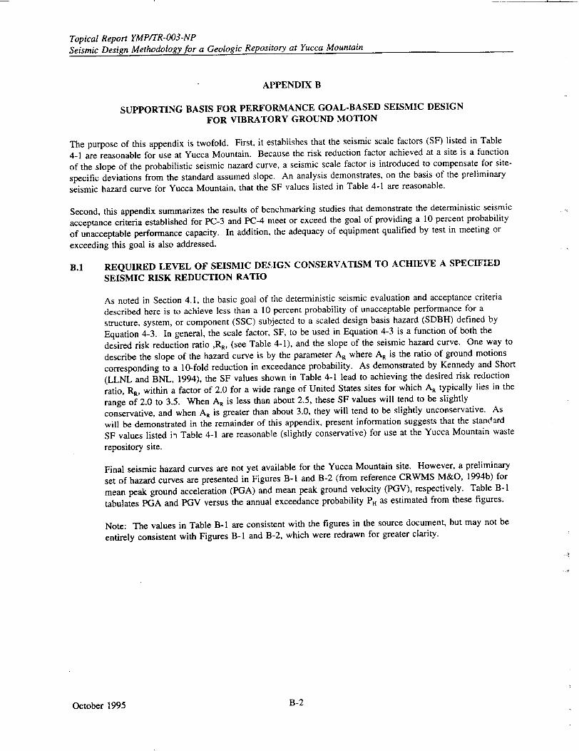
Topical Report YMP/TR-003-NP Seismic Design Methodology for a Geologic Repository at Yucca Mountain
APPENDIX B
SUPPORTING BASIS FOR PERFORMANCE GOAL-BASED SEISMIC DESIGN
FOR VIBRATORY GROUND MOTION
The purpose of this appendix is twofold. First, it establishes that the seismic scale factors (SF) listed in Table
4-1 are reasonable for use at Yucca Mountain. Because the risk reduction factor achieved at a site is a function
of the slope of the probabilistic seismic nazard curve, a seismic scale factor is introduced to compensate for site
specific deviations from the standard assumed slope. An analysis demonstrates, on the basis of the preliminary
seismic hazard curve for Yucca Mountain, that the SF values listed in Table 4-1 are reasonable.
Second, this appendix summarizes the results of benchmarking studies that demonstrate the deterministic seismic
acceptance criteria established for PC-3 and PC-4 meet or exceed the goal of providing a 10 percent probability
of unacceptable performance capacity. In addition, the adequacy of equipment qualified by test in meeting or
exceeding this goal is also addressed.
B.1 REQUIRED LEVEL OF SEISMIC DEH.GN CONSERVATISM TO ACHIEVE A SPECIFIED
SEISMIC RISK REDUCTION RATIO
As noted in Section 4.1, the basic goal of the deterministic seismic evaluation and acceptance criteria
described here is to achieve less than a 10 percent probability of unacceptable performance for a
structure, system, or component (SSC) subjected to a scaled design basis hazard (SDBH) defined by
Equation 4-3. In general, the scale factor, SF, to be used in Equation 4-3 is a function of both the
desired risk reduction ratio ,RR, (see Table 4-1), and the slope of the seismic hazard curve. One way to
describe the slope of the hazard curve is by the parameter A, where AR is the ratio of ground motions
corresponding to a 10-fold reduction in exceedance probability. As demonstrated by Kennedy and Short
(LLNL and BNL, 1994), the SF values shown in Table 4-1 lead to achieving the desired risk reduction
ratio, RR, within a factor of 2.0 for a wide range of United States sites for which AR typically lies in the
range of 2.0 to 3.5. When AR is less than about 2.5, these SF values will tend to be slightly
conservative, and when AR is greater than about 3.0, they will tend to be slightly unconservative. As
will be demonstrated in the remainder of this appendix, present information suggests that the standard
SF values listed ii Table 4-1 are reasonable (slightly conservative) for use at the Yucca Mountain waste
repository site.
Final seismic hazard curves are not yet available for the Yucca Mountain site. However, a preliminary
set of hazard curves are presented in Figures B-I and B-2 (from reference CRWMS M&O, 1994b) for
mean peak ground acceleration (PGA) and mean peak ground velocity (PGV), respectively. Table B-1
tabulates PGA and PGV versus the annual exceedance probability PH as estimated from these figures.
Note: The values in Table B-1 are consistent with the figures in the source document, but may not be
entirely consistent with Figures B-1 and B-2, which were redrawn for greater clarity.
October 1995 B-2
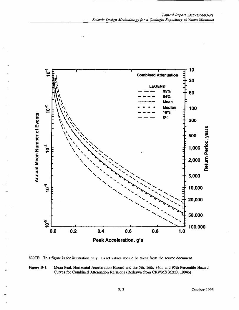
Topical Report YMPITR-003-NP
Seismic Design Methodology for a Geologic Repository at Yucca Mountain
0.0 0.2 0.4 0.6
Peak Acceleration, g's
0.8 1.0
10
20
50
100
200
500 )
1,000 0.
2,000
5,000
10,000
20,000
50,000
100,000
NOTE: This figure is for illustration only. Exact values should be taken from the source document.
Figure B-1. Mean Peak Horizontal Acceleration Hazard and the 5th, 16th, 84th, and 95th Percentile Hazard Curves for Combined Attenuation Relations (Redrawn from CRWMS M&O, 1994b)
October 1995
"6 0
4) Ct
0 w
m
B-3
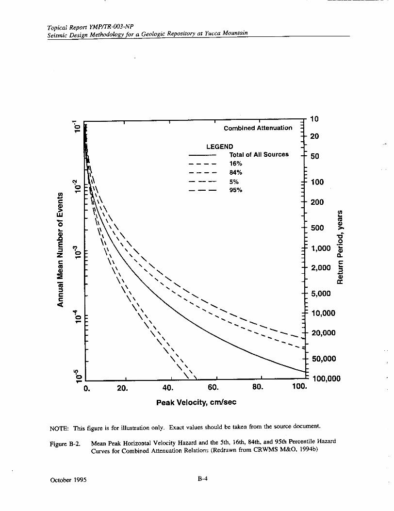
Topical Report YMP/TR-003-NP Seismic Design Methodology for a Geologic Repository at Yucca Mountain
Q~
0"
U,,
0
E z
tC Co 0.
<C
C" I
0 7l
0
1V
0.
10
20
50
100
200
Co 500
1,000 "
0~ 2,000 "
5,000
10,000
20,000
50,000
100,000
20. 40. 60. 80. 100.
Peak Velocity, cm/sec
NOTE: This figure is for illustration only. Exact values should be taken from the source document.
Figure B-2. Mean Peak Horizontal Velocity Hazard and the 5th, 16th, 84th, and 95th Percentile Hazard
Curves for Combined Attenuation Relations (Redrawn from CRWMS M&O, 1994b)
October 1995 B-4
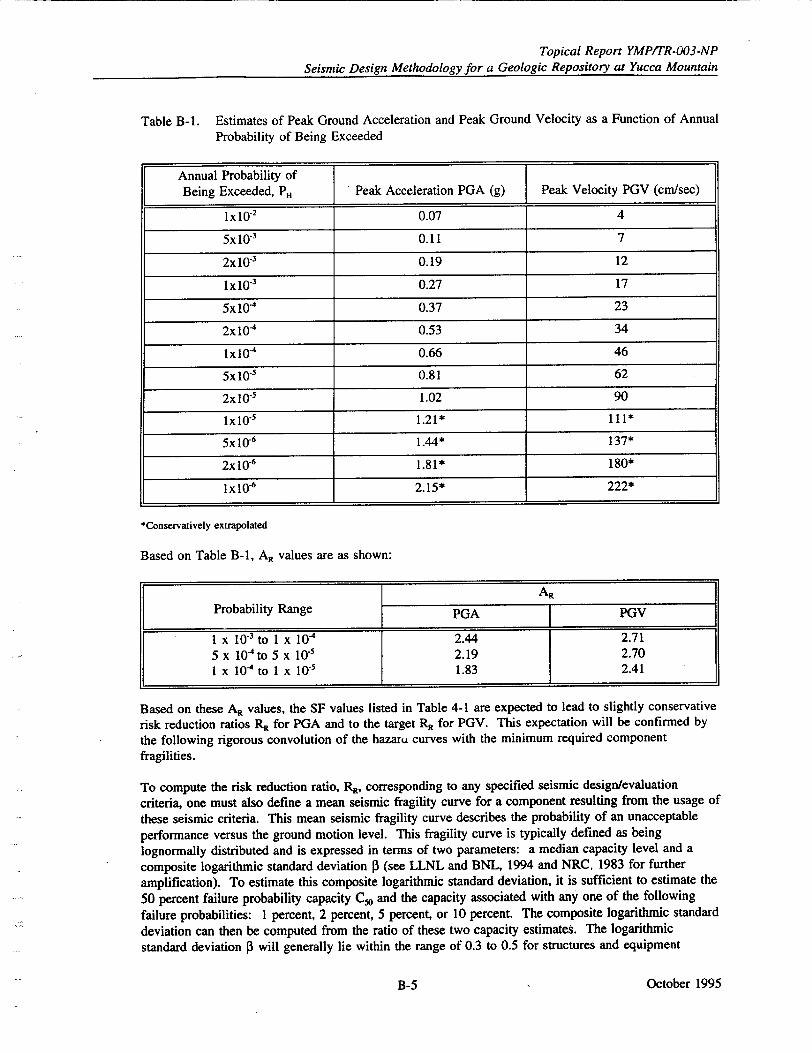
Topical Report YMPITR-003-NP
Seismic Design Methodology for a Geologic Repository at Yucca Mountain
Table B-I. Estimates of Peak Ground Acceleration and Peak Ground Velocity as a Function of Annual Probability of Being Exceeded
Annual Probability of Being Exceeded, PH Peak Acceleration PGA (g) Peak Velocity PGV (cm/sec)
Ix10-2 0.07 4
5xl10 3 0.11 7
2x10 3 0.19 12
1x10⁻³ 0.27 17
5x10⁻⁴ 0.37 23
2x10⁻⁴ 0.53 34
Ix104 0.66 46
5x10 5 0.81 62
2x 10s 1.02 90
lx10"s 1.21* 111*
5x 10r6 1.44* 137*
2xl0r6 1.81* 180*
lxlO6 2.15* 222*
*Conservatively extrapolated
Based on Table B-I, A, values are as shown:
AR
Probability Range PGA PGV
1 x I0-3 to I X 10-4 2.44 2.71 5 x 10⁻⁴to 5 x 10.' 2.19 2.70 1 x 10⁴ to I X 10-5 1.83 2.41
Based on these AR values, the SF values listed in Table 4-1 are expected to lead to slightly conservative risk reduction ratios R, for PGA and to the target RR for PGV. This expectation will be confirmed by
the following rigorous convolution of the hazaru curves with the minimum required component fragilities.
To compute the risk reduction ratio, RR, corresponding to any specified seismic design/evaluation
criteria, one must also define a mean seismic fragility curve for a component resulting from the usage of
these seismic criteria. This mean seismic fragility curve describes the probability of an unacceptable
performance versus the ground motion level. This fragility curve is typically defined as being lognormally distributed and is expressed in terms of two parameters: a median capacity level and a
composite logarithmic standard deviation 13 (see LLNL and BNL, 1994 and NRC, 1983 for further amplification). To estimate this composite logarithmic standard deviation, it is sufficient to estimate the
50 percent failure probability capacity C50 and the capacity associated with any one of the following failure probabilities: 1 percent, 2 percent, 5 percent, or 10 percent. The composite logarithmic standard
deviation can then be computed from the ratio of these two capacity estimates. The logarithmic
standard deviation 0 will generally lie within the range of 0.3 to 0.5 for structures and equipment
October 1995B-5
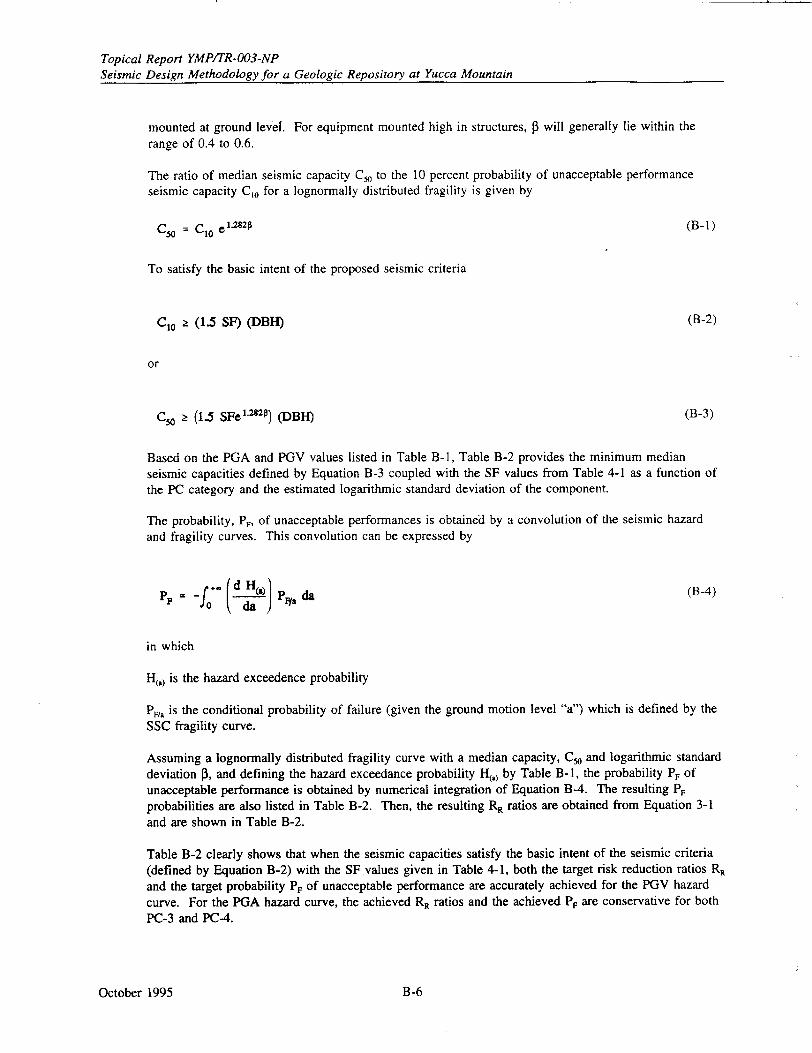
Topical Report YMP/TR-003-NP Seismic Design Methodology for a Geologic Repository at Yucca Mountain
mounted at ground level. For equipment mounted high in structures, P will generally lie within the range of 0.4 to 0.6.
The ratio of median seismic capacity C, to the 10 percent probability of unacceptable performance seismic capacity Co for a lognormally distributed fragility is given by
C50 = CI0 e1 .•2 1 (B-i)
To satisfy the basic intent of the proposed seismic criteria
C10 I (1.5 SF) (DBI-) (B-2)
or
C50 (1.5 SFe' 1 ) (DBI) (B-3)
Based on the PGA and PGV values listed in Table B-1, Table B-2 provides the minimum median seismic capacities defined by Equation B-3 coupled with the SF values from Table 4-1 as a function of the PC category and the estimated logarithmic standard deviation of the component.
The probability, PF, of unacceptable performances is obtained by a convolution of the seismic hazard and fragility curves. This convolution can be expressed by
P F~ (dH., Ply. da (B-4)
in which
H(a) is the hazard exceedence probability
PF/, is the conditional probability of failure (given the ground motion level "a") which is defined by the SSC fragility curve.
Assuming a lognormally distributed fragility curve with a median capacity, C5o and logarithmic standard deviation P, and defining the hazard exceedance probability H(.) by Table B-i, the probability P, of unacceptable performance is obtained by numerical integration of Equation B-4. The resulting PF probabilities are also listed in Table B-2. Then, the resulting RR ratios are obtained from Equation 3-1 and are shown in Table B-2.
Table B-2 clearly shows that when the seismic capacities satisfy the basic intent of the seismic criteria (defined by Equation B-2) with the SF values given in Table 4-1, both the target risk reduction ratios RR
and the target probability PF of unacceptable performance are accurately achieved for the PGV hazard curve. For the PGA hazard curve, the achieved RR ratios and the achieved PF are conservative for both PC-3 and PC-4.
October 1995 B-6
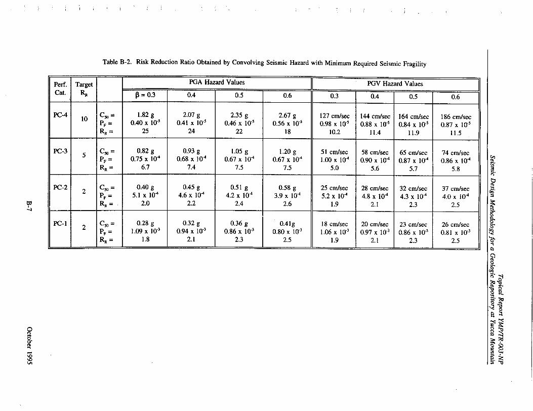
Table B-2. Risk Reduction Ratio Obtained by Convolving Seismic Hazard with Minimum Required Seismic Fragility
LA
Perf. Target PGA Hazard Values PGV Hazard Values Cat. RR = 0.3 0.4 0.5 0.6 0.3 0.4 0.5 0.6
PC-4 10 C5 = 1.82 g 2.07 g 2.35 g 2.67 g 127 cm/sec 144 cm/sec 164 cm/sec 186 cm/sec PF = 0.40 x 10⁻⁵ 0.41 x 10.5 0.46 x 10"' 0.56 x 10.5 0.98 x I0V 0.88 x 10. 0.84 x 10s 0.87 x 10⁵ RR 25 24 22 18 10.2 11.4 11.9 11.5
PC-3 C5 = 0.82 g 0.93 g 1.05 g 1.20 g 51 cm/sec 58 cm/sec 65 cm/sec 74 cm/sec 5 PF= 0.75 x 10"4 0.68 x 10⁻⁴ 0.67 x 10"4 0.67 x 10⁻⁴ 1.00 x 10⁴ 0.90 x 10⁻⁴ 0.87 x 10⁻⁴ 0.86 x 10⁻⁴ RR = 6.7 7.4 7.5 7.5 5.0 5.6 5.7 5.8
PC-2 C° = 0.40 g 0.45 g 0.51 g 0.58 g 25 cm/sec 28 cm/sec 32 cm/sec 37 cm/sec 2 PF = 5.1 x 10"' 4.6 x 10"' 4.2 x 10⁻⁴ 3.9 x 10"4 5.2 x 10"4 4.8 x 10⁻⁴ 4.3 x 10⁻⁴ 4.0 x 10"4
R = 2.0 2.2 2.4 2.6 1.9 2.1 2.3 2.5
PC-1 C5 = 0.28 g 0.32 g 0.36 g 0.41g 18 cm/sec 20 cm/sec 23 cm/sec 26 cm/sec
2 PF = 1.09 x 10³ 0.94 x 10"3 0.86 x 10⁻³ 0.80 x 10"3 1.06 X 10"3 0.97 x I03 0.86 x 10"' 0.81 x 10⁻³
RR = 1.8 2.1 2.3 2.5 1.9 2.1 2.3 2.5
2Z
q5.
•t.
Topical Report YMP/TR-003-NP Seismic Design Methodology for a Geologic Repository at Yucca Mountain
At target RR ratios of 5 and 10, the required SF to achieve the target RR is a function of the slope
coefficient AR as shown in Figure B-3 (LLNL and BNL, 1994).
Using Figure B-3, the required scale factor to accurately achieve the target RR for some example AR
ratios are
Target R, AR SF
1.8 1.0 10
2.4 1.2
2.3 0.9 5
2.7 1.0
The lower AR values in the above table are consistent with the PGA hazard curve while the larger AR
values are consistent with the PGV hazard curve. This comparison also confirms that the values in
Table 4-1 are appropriate for the PGV hazard curve and slightly conservative for the PGA hazard curve
defined in Table B-1.
Since the final and approved seismic hazard curves have not yet been developed for the Yucca
Mountain repository site, the final selection for SF values for PC-3 and PC-4 cannot be made at this
time. The final selected scale factors SF for PC-3 and PC-4 will be the larger of the SF values from
Table 4-1 or from Figure B-3 rounded to the closest 0.05. Since it is expected that the final hazard
curves will have slopes (AR coefficients) similar to those in Figures B-I and B-2, it is expected that the
final selected SF values will be those in Table 4-1. The scale factors associated with PC-I and PC-2
(RR = 2) are not sensitive to the hazard curve slope and will be the Table 4-1 value of 0.67, as can be
observed from a plot of RR versus AR for SF = 0.67 (see Figure B-4).
October 1995 B-8
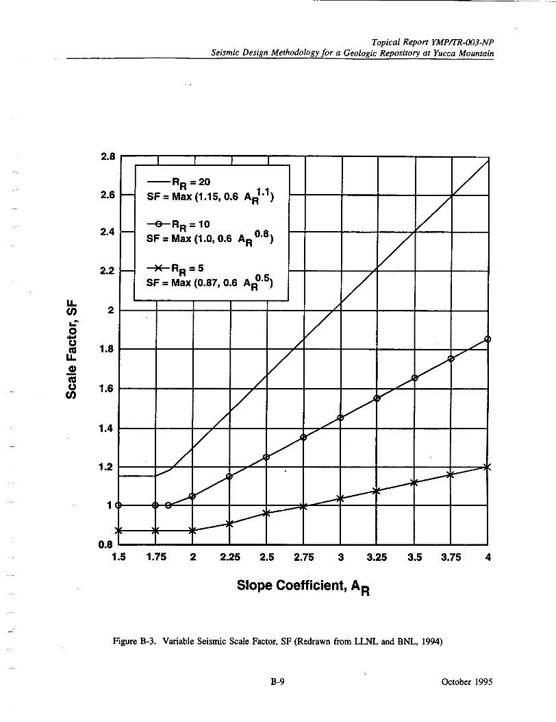
Topical Report YMP/TR-003-NP Seismic Design Methodology for a Geologic Repository at Yucca Mountain
1.75 2 2.25 2.5 2.75 3 3.25 3.5 3.75 4
Slope Coefficient, AR
Figure B-3. Variable Seismic Scale Factor, SF (Redrawn from LLNL and BNL, 1994)
October 1995
2.8
2.6
2.4
2.2
2
1.8
1.6
IL
0 cc. 0L
1.4
1.2
1
0.8 L1.5
B-9
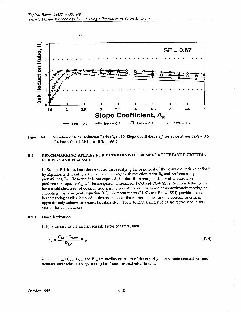
Topical Report YMPITR-003-NP Seismic Design Methodology for a Geologic Repository at Yucca Mountain
4
3t
cc
0
G) 01
1.5 2 2.5 3 3.5 4 4.5
Slope Coefficient, AR
- beta = 0.3 --- beta = 0.4 -4- beta = 0.5 -4- beta= 0.6
Figure B-4. Variation of Risk Reduction Ratio (RR) with Slope Coefficient (AR) for Scale Factor (SF) = 0.67 (Redrawn from LLNL and BNL, 1994)
B.2 BENCHMARKING STUDIES FOR DETERMINISTIC SEISMIC ACCEPTANCE CRITERIA FOR PC-3 AND PC-4 SSCs
In Section B. 1 it has been demonstrated that satisfying the basic goal of the seismic criteria as defined
by Equation B-2 is sufficient to achieve the target risk reduction ratios RR and performance goal probabilities, P, However, it is not expected that the 10 percent probability of unacceptable performance capacity C,0 will be computed. Instead, for PC-3 and PC-4 SSCs, Sections 4 through 8
have established a set of deterministic seismic acceptance criteria aimed at approximately meeting or
exceeding this basic goal (Equation B-2). A recent report (LLNL and BNL, 1994) provides some benchmarking studies intended to demonstrate that these deterministic seismic acceptance criteria approximately achieve or exceed Equation B-2. These benchmarking studies are reproduced in this section for completeness.
B.2.1 Basic Derivation
If F. is defined as the median seismic factor of safety, then
F, = C50 - DNs0 F• (B-5)
in which C50, DNs,,, Ds5 , and F. are median estimates of the capacity, non-seismic demand, seismic demand, and inelastic energy absorption factor, respectively. In turn,
October 1995
2
1
0'
SF = 0.67 . . . . . ........................
0 Q eA A ............C1 ....... ...... .... ..
5 5.5
B-10
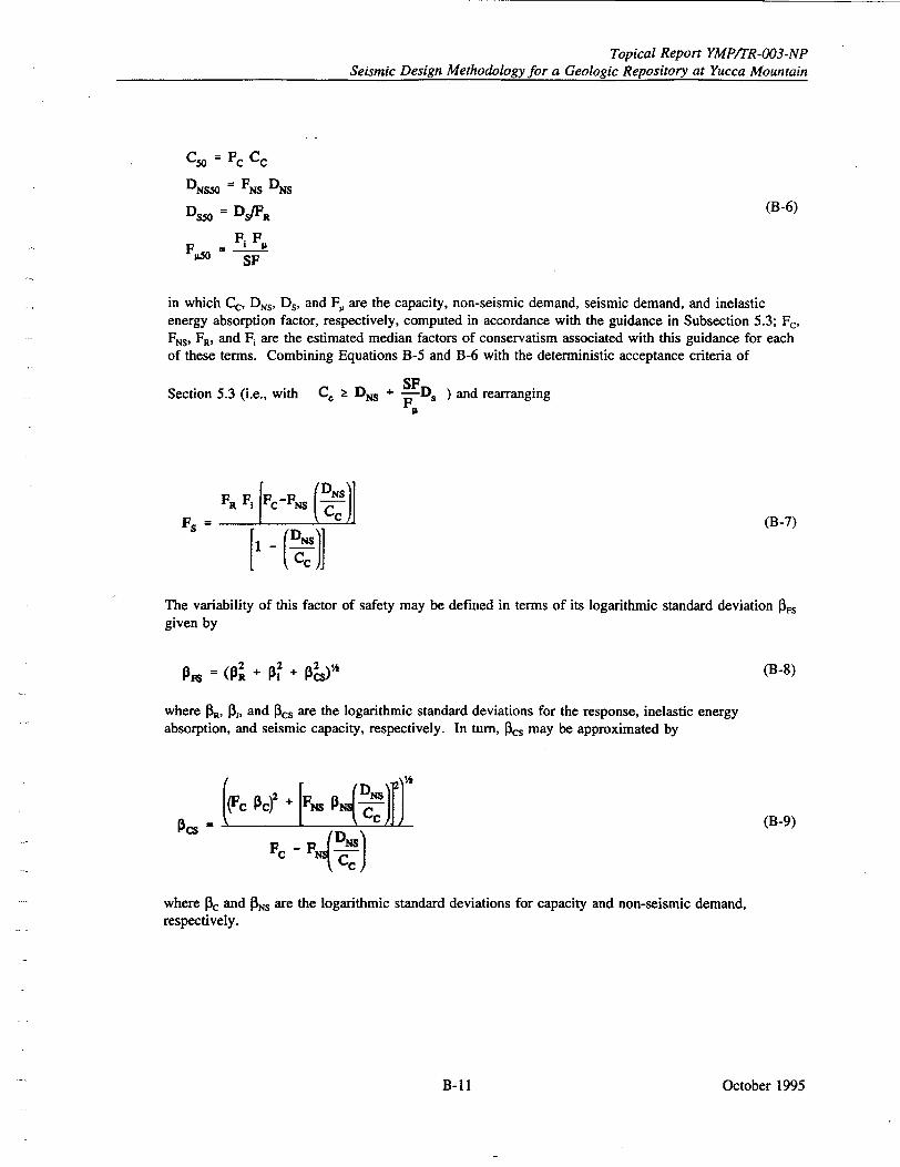
Topical Report YMP/TR-003-NP Seismic Design Methodology for a Geologic Repository at Yucca Mountain
C50 = C
DNS5 = FNS DNS
D = Ds/FR (B-6)
FPM 0= FFp SF
in which Cc, DNs, Ds, and F, are the capacity, non-seismic demand, seismic demand, and inelastic energy absorption factor, respectively, computed in accordance with the guidance in Subsection 5.3; F, FNs, FR, and Fi are the estimated median factors of conservatism associated with this guidance for each of these terms. Combining Equations B-5 and B-6 with the deterministic acceptance criteria of
Section 5.3 (i.e., with C. D + SFD ) and rearranging FIL
FR F, FC -NS (DNsl FS ( J cc (B-7)
The variability of this factor of safety may be defined in terms of its logarithmic standard deviation P3s given by
(p +~ p2 2 ihP& (B-8)
where 1•R, P3i, and 13cs are the logarithmic standard deviations for the response, inelastic energy absorption, and seismic capacity, respectively. In turn, Pcs may be approximated by
Pc)s = (I N CcJJ (B-9) PC F4P)
where oc and Ps are the logarithmic standard deviations for capacity and non-seismic demand, respectively.
October 1995B-11
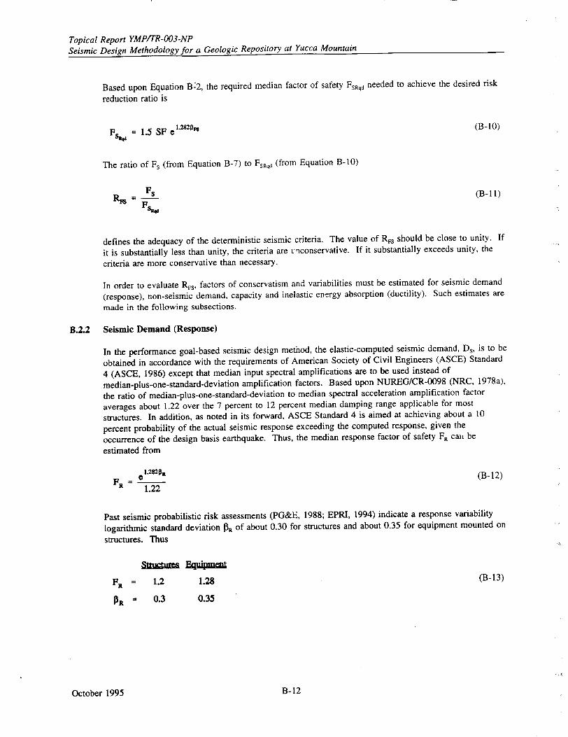
Topical Report YMP/TR-003-NP Seismic Design Methodology for a Geologic Repository at Yucca Mountain
Based upon Equation B-2, the required median factor of safety FsRqd needed to achieve the desired risk
reduction ratio is
FSEW= 1.5 SF e"'820, (B-10)
The ratio of Fs (from Equation B-7) to FsRqd (from Equation B-10)
Fs• RN F- (B-il1)
defines the adequacy of the deterministic seismic criteria. The value of RFs should be close to unity. If
it is substantially less than unity, the criteria are unconservative. If it substantially exceeds unity, the
criteria are more conservative than necessary.
In order to evaluate RFs, factors of conservatism and variabilities must be estimated for seismic demand
(response), non-seismic demand, capacity and inelastic energy absorption (ductility). Such estimates are
made in the following subsections.
B.2.2 Seismic Demand (Response)
In the performance goal-based seismic design method, the elastic-computed seismic demand, Ds, is to be
obtained in accordance with the requirements of American Society of Civil Engineers (ASCE) Standard
4 (ASCE, 1986) except that median input spectral amplifications are to be used instead of
median-plus-one-standard-deviation amplification factors. Based upon NUREG/CR-0098 (NRC, 1978a),
the ratio of median-plus-one-standard-deviation to median spectral acceleration amplification factor
averages about 1.22 over the 7 percent to 12 percent median damping range applicable for most
structures. In addition, as noted in its forward, ASCE Standard 4 is aimed at achieving about a 10
percent probability of the actual seismic response exceeding the computed response, given the
occurrence of the design basis earthquake. Thus, the median response factor of safety FR call be
estimated from
FR .• (B-12)
1.22
Past seismic probabilistic risk assessments (PG&E, 1988; EPRI, 1994) indicate a response variability
logarithmic standard deviation N3 of about 0.30 for structures and about 0.35 for equipment mounted on
structures. Thus
str ts EW1q90mu
FR = 1.2 1.28 (B-13)
piR = 0.3 0.35
October 1995 B- 12
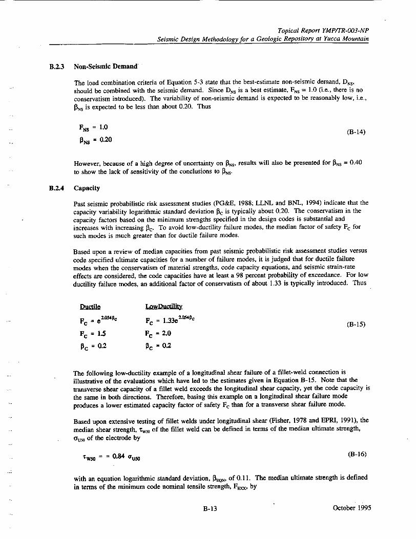
Topical Report YMPITR-003-NP
Seismic Design Methodology for a Geologic Repository at Yucca Mountain
B.2.3 Non-Seismic Demand
The load combination criteria of Equation 5-3 state that the best-estimate non-seismic demand, DNs, should be combined with the seismic demand. Since Drs is a best estimate, FNs = 1.0 (i.e., there is no conservatism introduced). The variability of non-seismic demand is expected to be reasonably low, i.e.,
[3 Ns is expected to be less than about 0.20. Thus
FNS =1.0 (B-14)
PNS = 0.20
However, because of a high degree of uncertainty on Ns, results will also be presented for Ns = 0.40
to show the lack of sensitivity of the conclusions to PNS.
B.2.4 Capacity
Past seismic probabilistic risk assessment studies (PG&E, 1988; LLNL and BNL, 1994) indicate that the
capacity variability logarithmic standard deviation 03c is typically about 0.20. The conservatism in the
capacity factors based on the minimum strengths specified in the design codes is substantial and increases with increasing 0c. To avoid low-ductility failure modes, the median factor of safety Fc for such modes is much greater than for ductile failure modes.
Based upon a review of median capacities from past seismic probabilistic risk assessment studies versus
code specified ultimate capacities for a number of failure modes, it is judged that for ductile failure
modes when the conservatism of material strengths, code capacity equations, and seismic strain-rate effects are considered, the code capacities have at least a 98 percent probability of exceedance. For low
ductility failure modes, an additional factor of conservatism of about 1.33 is typically introduced. Thus
Vu e LowDueftt_
Fc = e "054C FC = 1.33e2" • (B-15)
Fc = 1..5 Fc = 2.0 P3C = 0.2 P3C = 0.2
The following low-ductility example of a longitudinal shear failure of a fillet-weld connection is
illustrative of the evaluations which have led to the estimates given in Equation B-15. Note that the transverse shear capacity of a fillet weld exceeds the longitudinal shear capacity, yet the code capacity is
the same in both directions. Therefore, basing this example on a longitudinal shear failure mode
produces a lower estimated capacity factor of safety Fc than for a transverse shear failure mode.
Based upon extensive testing of fillet welds under longitudinal shear (Fisher, 1978 and EPRI, 1991), the
median shear strength, rw, of the fillet weld can be defined in terms of the median ultimate strength,
cou, of the electrode by
w0 - 0.84 ous0 (B-16)
with an equation logarithmic standard deviation, PtQN, of 0. 11. The median ultimate strength is defined
in terms of the minimum code nominal tensile strength, F~xx, by
October 1995B-13
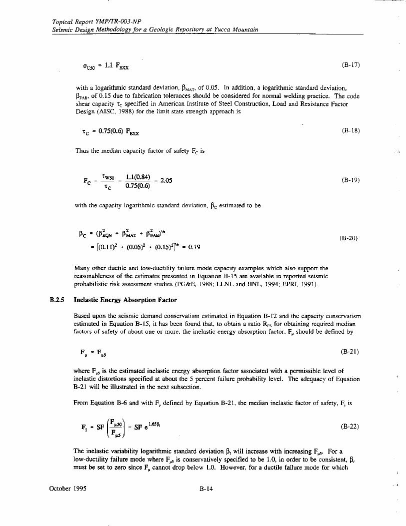
Topical Report YMP/TR-003-NP Seismic Design Methodology for a Geologic Repository at Yucca Mountain
ou50 = 1.1 F= (B-17)
with a logarithmic standard deviation, P3 MAT, of 0.05. In addition, a logarithmic standard deviation, 3FAB, of 0.15 due to fabrication tolerances should be considered for normal welding practice. The code shear capacity rc specified in American Institute of Steel Construction, Load and Resistance Factor Design (AISC, 1988) for the limit state strength approach is
Tc = 0.75(0.6) Fm~x (B-18)
Thus the median capacity factor of safety Fc is
Fcrw wo 1.1(0.84) _ 2.05 (B-19)
"tc 0.75(0.6)
with the capacity logarithmic standard deviation, Pc estimated to be
=e (13 + MAT + AB) (B-20)
= [(0.11)2 + (0.05)2 + (0.15)21'%" = 0.19
Many other ductile and low-ductility failure mode capacity examples which also support the reasonableness of the estimates presented in Equation B-15 are available in reported seismic probabilistic risk assessment studies (PG&E, 1988; LLNL and BNL, 1994; EPRI, 1991).
B.2.5 Inelastic Energy Absorption Factor
Based upon the seismic demand conservatism estimated in Equation B-12 and the capacity conservatism estimated in Equation B-15, it has been found that, to obtain a ratio RFs for obtaining required median factors of safety of about one or more, the inelastic energy absorption factor, F, should be defined by
F• = F 0 (B-2 1)
where F. is the estimated inelastic energy absorption factor associated with a permissible level of inelastic distortions specified at about the 5 percent failure probability level. The adequacy of Equation B-21 will be illustrated in the next subsection.
From Equation B-6 and with FP defined by Equation B-21, the median inelastic factor of safety, Fi is
F, = SF (.5°t= SF •1"•j (B-22)
The inelastic variability logarithmic standard deviation Pi will increase with increasing F•. For a low-ductility failure mode where F. is conservatively specified to be 1.0, in order to be consistent, • must be set to zero since F, cannot drop below 1.0. However, for a ductile failure mode for which
October 1995 B- 14
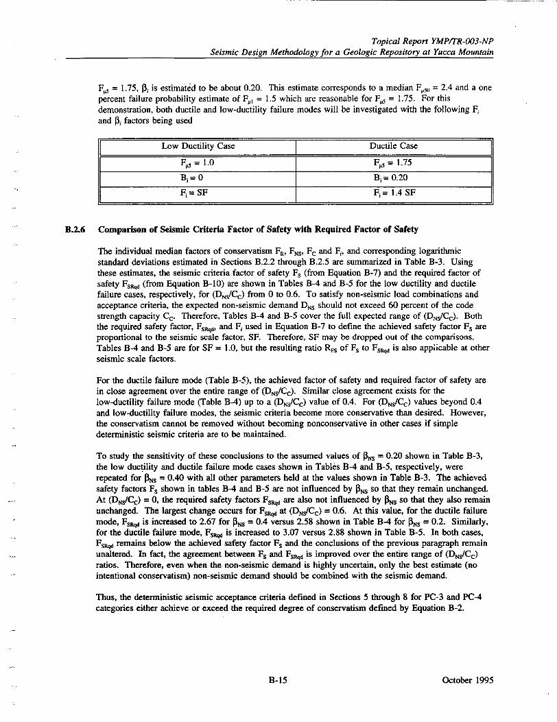
Topical Report YMP/TR-003-NP Seismic Design Methodology for a Geologic Repository at Yucca Mountain
F0 = 1.75, 03, is estimated to be about 0.20. This estimate corresponds to a median F•) = 2.4 and a one percent failure probability estimate of F., = 1.5 which are reasonable for F.5 = 1.75. For this demonstration, both ductile and low-ductility failure modes will be investigated with the following F1 and P3i factors being used
Low Ductility Case Ductile Case
5= 1.0 F= 1.75
B-= 0 Bi = 0.20
F = SF Fj = 1.4 SF
B.2.6 Comparison of Seismic Criteria Factor of Safety with Required Factor of Safety
The individual median factors of conservatism FR, FNs, Fc and F,, and corresponding logarithmic standard deviations estimated in Sections B.2.2 through B.2.5 are summarized in Table B-3. Using these estimates, the seismic criteria factor of safety Fs (from Equation B-7) and the required factor of safety FsRq (from Equation B-10) are shown in Tables B-4 and B-5 for the low ductility and ductile failure cases, respectively, for (DNs/Cc) from 0 to 0.6. To satisfy non-seismic load combinations and acceptance criteria, the expected non-seismic demand DNs should not exceed 60 percent of the code strength capacity Cc. Therefore, Tables B-4 and B-5 cover the full expected range of (DNs/CC). Both the required safety factor, FspRI, and F1 used in Equation B-7 to define the achieved safety factor Fs are proportional to the seismic scale factor, SF. Therefore, SF may be dropped out of the comparisons. Tables B-4 and B-5 are for SF = 1.0, but the resulting ratio RFs of Fs to FsRqd is also applicable at other seismic scale factors.
For the ductile failure mode (Table B-5), the achieved factor of safety and required factor of safety are in close agreement over the entire range of (DNS/Cc). Similar close agreement exists for the low-ductility failure mode (Table B4) up to a (DNS/CC) value of 0.4. For (DNS/Cc) values beyond 0.4 and low-ductility failure modes, the seismic criteria become more conservative than desired. However, the conservatism cannot be removed without becoming nonconservative in other cases if simple deterministic seismic criteria are to be maintained.
To study the sensitivity of these conclusions to the assumed values of P3 s = 0.20 shown in Table B-3, the low ductility and ductile failure mode cases shown in Tables B-4 and B-5, respectively, were repeated for INs = 0.40 with all other parameters held at the values shown in Table B-3. The achieved safety factors Fs shown in tables B4 and B-5 are not influenced by fINS so that they remain unchanged. At (DNs/Cc) = 0, the required safety factors Fs5 are also not influenced by PNs so that they also remain unchanged. The largest change occurs for FsRqd at (DNs/Cc) = 0.6. At this value, for the ductile failure mode, Fs5 , is increased to 2.67 for PNs = 0.4 versus 2.58 shown in Table B4 for JONS = 0.2. Similarly, for the ductile failure mode, FsW is increased to 3.07 versus 2.88 shown in Table B-5. In both cases, Fs. remains below the achieved safety factor Fs and the conclusions of the previous paragraph remain unaltered. In fact, the agreement between Fs and FsRqd is improved over the entire range of (DNs/Cc) ratios. Therefore, even when the non-seismic demand is highly uncertain, only the best estimate (no intentional conservatism) non-seismic demand should be combined with the seismic demand.
Thus, the deterministic seismic acceptance criteria defined in Sections 5 through 8 for PC-3 and PC4 categories either achieve or exceed the required degree of conservatism defined by Equation B-2.
October 1995B- 15
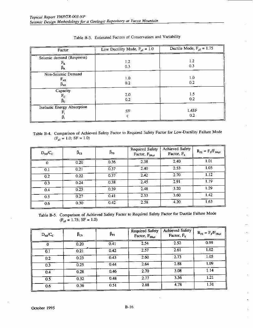
Topical Report YMPITR-003-NP
Seismic Design Methodology for a Geologic Repository at Yucca Mountain
Table B-3. Estimated Factors of Conservatism and Variability
Factor Low Ductility Mode, F5 = 1.0 Ductile Mode, F5 = 1.75
Seismic demand (Response) F, 1.2 1.2 PR 0.3 0.3
Non-Seismic Demand FNS 1.0 1.0
PS 0.2 0.2
Capacity Fc 2.0 1.5
PC 0.2 0.2
Inelastic Energy Absorption F, SF 1.4SF
i 0.2
Table B-4. Comparison of Achieved Safety Factor to Required Safety Factor for Low-Ductility Failure Mode
(F5 = 1.0; SF = 1.0)
DNS/CC Required Safety Achieved Safety RFs Fs/FsRqd Factor, FSRqd Factor, F,
0 0.20 0.36 2.38 2.40 1.01
0.1 0.21 0.37 2.40 2.53 1.05
0.2 0.22 0.37 2.42 2.70 1.12
0.3 0.24 0.38 2.45 2.91 1.19
0.4 0.25 0.39 2.48 3.20 1.29
0.5 0.27 0.41 2.53 3.60 1.42
0.6 0.30 0.42 2.58 4.20 1.63
Table B-5. Comparison of Achieved Safety Factor to Required Safety Factor for Ductile Failure Mode
(FP - 1.75; SF = 1.0)
Required Safety Achieved Safety Rs = Fs/Fs~d D[s/Cc PCs _ Fs Factor, Fsvo Factor, Fs 1
0 0.20 0.41 2.54 2.52 0.99
0.1 0.21 0.42 2.57 2.61 1.02
0.2 0.23 0.43 2.60 2.73 1.05
0.3 0.25 0.44 2.64 2.88 1.09
0.4 0.28 0.46 2.70 3.08 1.14
0.5 0.32 0.48 2.77 3.36 1.21
0.6 0.36 0.51 2.88 4.78 1.31
October 1995 B-16
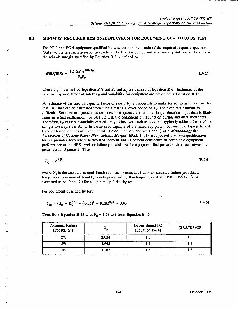
Topical Report YMP/TR-003-NP Seismic Design Methodology for a Geologic Repository at Yucca Mountain
B.3 MINIMUM REQUIRED RESPONSE SPECTRUM FOR EQUIPMENT QUALIFIED BY TEST
For PC-3 and PC-4 equipment qualified by test, the minimum ratio of the required response spectrum (RRS) to the in-structure response spectrum (IRS) at the component attachment point needed to achieve the seismic margin specified by Equation B-2 is defined by
1.5 SF e "'on (B-23) FRFC
where Ns is defined by Equation B-8 and FR and Fc are defined in Equation B-6. Estimates of the median response factor of safety FR and variability for equipment are presented in Equation B-13.
An estimate of the median capacity factor of safety Fc is impossible to make for equipment qualified by test. All that can be estimated from such a test is a lower bound on Fo and even this estimate is difficult. Standard test procedures use broader frequency content and longer duration input than is likely from an actual earthquake. To pass the test, the equipment must function during and after such input. Therefore, Fc must substantially exceed unity. However, such tests do not typically address the possible sample-to-sample variability in the seismic capacity of the tested equipment, because it is typical to test three or fewer samples of a component. Based upon Appendixes J and Q of A Methodology for Assessment of Nuclear Power Plant Seismic Margin (EPRI, 1991), it is judged that such qualification testing provides somewhere between 90 percent and 98 percent confidence of acceptable equipment performance at the RRS level, or failure probabilities for equipment that passed such a test between 2
percent and 10 percent. Thus
Fc 2 V, (B-24)
where XP is the standard normal distribution factor associated with an assumed failure probability. Based upon a review of fragility results presented by Bandyopadhyay et al., (NRC, 1991a), Pc is estimated to be about .20 for equipment qualified by test.
For equipment qualified by test
R= ( a[ + = ((0.35)V + (0.20)2)"' = 0.40 (B-25)
Thus, from Equation B-23 with F, = 1.28 and from Equation B-13
Probabil (Equation B-24)
2% 2.054 1.5 1.3
5% 1.645 1.4 1.4
10% 1.282 1.3 1.5
October 1995B-17
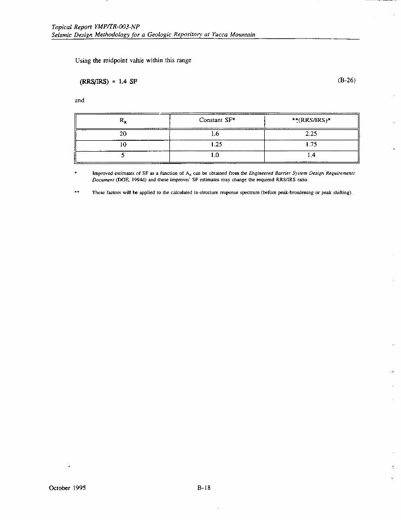
Topical Report YMP/TR-003-NP Seismic Design Methodology for a Geologic Repository at Yucca Mountain
Using the midpoint value within this range
(B-26)(RRS/IRS) = 1.4 SF
and
RR Constant SF* **(RRS/IRS)*
20 1.6 2.25
10 1.25 1.75
5 1.0 1.4
Improved estimates of SF as a function of A. can be obtained from the Engineered Barrier System Design Requirements
Document (DOE, 1994d) and these improvec" SF estimates may change the required RRS/IRS ratio.
These factors will be applied to the calculated in-structure response spectrum (before peak-broadening or peak shifting),
October 1995 B-18
Topical Report YMP/TR-003-NP Seismic Design Methodology for a Geologic Repository at Yucca Mountain
APPENDIX C
RELATIONSHIP BETWEEN THE PERFORMANCE GOAL-BASED AND THE NUCLEAR REGULATORY COMMISSION NUCLEAR POWER
PLANT SEISMIC DESIGN CRITERIA
October 1995C-1
Topical Report YMPITR-003-NP Seismic Design Methodology for a Geologic Repository at Yucca Mountain
APPENDIX C
RELATIONSHIP BETWEEN THE PERFORMANCE GOAL-BASED AND THE NUCLEAR REGULATORY COMMISSION NUCLEAR POWER
PLANT SEISMIC DESIGN CRITERIA
The performance goal-based seismic design (PGSD) criteria described in this report are very similar to those currently used by the Nuclear Regulatory Commission (NRC) for reviewing nuclear power plant designs. The PGSD method, however, incorporates certain changes that are based on about two decades of experience in using NRC's nuclear power plant seismic design provisions. These changes reflect the latest developments in the state-of-the-art in the field of seismic and structural engineering, and attempt to make the overall seismic design process more consistent and rational. The relation of these changes to current NRC practice is discussed below for two broad categories: seismic hazard determination and seismic design method.
In general, the discussion below, especially the numerical values of various design related factors cited here (e.g., SF, F,, F,, see Section C.2.B below) is applicable to surface facility SSC design for ground motion.
C.A SEISMIC HAZARD DETERMINATION
As discussed in Section 4 of this document and shown below, the seismic hazard levels of comparable categories of structures, systems, and components (SSCs) determined by the PGSD method, are either identical to or approximately the same as those used in the existing nuclear plant designs (for PC-4) or in Uniform Building Code (UBC)-type designs (for PC-I and PC-2). The primary difference between the two methods lies in the way the design seismic level is determined: the method proposed in Seismic Topical Report I (DOE, 1994a) is basically probabilistic, while the current NRC-approved method for nuclear power plants is purely deterministic.
In the PGSD method, the ground motion level is determined from seismic hazard curves at annual probabilities of exceedance (PH) values applicable for the SSC performance category (see Table 4-1). Accordingly, for repository SSCs having the highest performance goal (i.e., for PC-4 SSCs), design seismic loads are determined for seismic motions associated with a P. value of I x 10-4 per year (see Table 4-1). On the other hand, although in the process of revision, present NRC regulations pertaining to seismic hazard assessment for nuclear power plants use a deterministic approach, and these plants are designed so that safety systems do not fail if subjected to a safe shutdown earthquake. The safe shutdown earthquake generally represents the expected ground motion at the site, either from the largest historic earthquake within the tectonic province within which the site is located, or from an assessment of the maximum earthquake potential of the appropriate tectonic structure or capable fault closest to the site.
This approach is used to establish seismic design levels at existing nuclear power plants. While this deterministic approach may appear to provide absolute assurance that future seismic events will be within the seismic design basis, recent probabilistic seismic hazard analyses for nuclear power plant sites in the eastern and central United States show that this is not the case. The annual probability that for these plants the safe shutdown earthquake response spectra will be exceeded ranges from about I x 10'- to 1 x IV. (Figure C-I). In determining safe shutdown earthquakes within the regulatory environment to guide design of Seismic Category I SSCs, weighing of the data, interpretations, and uncertainties implicitly resulted in this degree of conservatism. The Department of Energy (DOE) approach for seismic hazard assessment at Yucca Mountain accepts this level of conservatism (for PC-4 SSCs) and determines the appropriate level of seismic hazard for design through an explicit incorporation of data, interpretations, and their uncertainties. The method for this explicit incorporation of uncertainties is the probabilistic seismic hazard assessment described in the DOE's first seismic topical report (DOE, 1994a).
October 1995 C-2
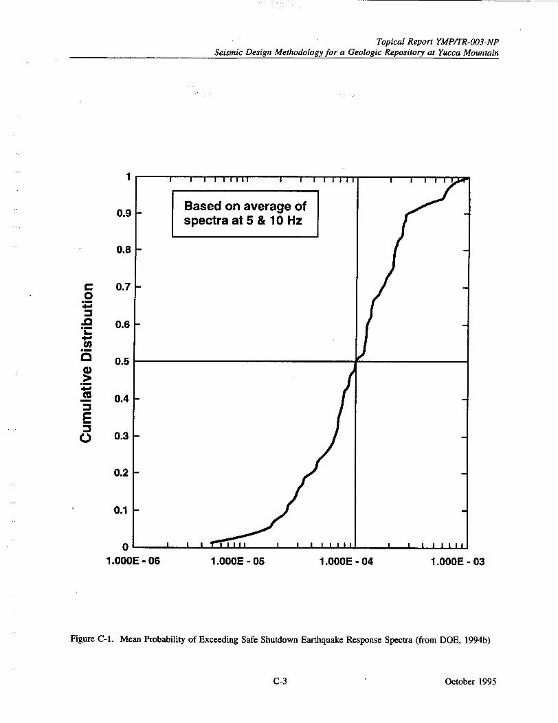
Topical Report YMP/TR-003-NP Seismic Design Methodology for a Geologic Repository at Yucca Mountain
1
0.9
0.8
0.7
0.6
0.5
0.4
0.3
0.2
0.1
0 1.OOOE - 06 1.OOOE - 05 1.OOOE - 04 1.000E - 03
Figure C-I. Mean Probability of Exceeding Safe Shutdown Earthquake Response Spectra (from DOE, 1994b)
October 1995
0 0
0m
Co .E 0m
C-3
Topical Report YMPITR-003-NP Seismic Design Methodology for a Geologic Repository at Yucca Mountain
Figure C-I also demonstrates that, for two-thirds of these plants, the safe shutdown earthquake spectra
correspond to probabilities between about 0.4 x 10⁴ and 2.5 x 10⁴ . Hence, the specified mean hazard
probability level of I x 10' in the proposed method for PC-4 is consistent with commercial nuclear power plant safe shutdown earthquake levels.
For non-safety related SSCs, the DOE goal is again to achieve the same level of conservatism as for the
non-safety related SSCs at a nuclear power plant. The level of seismic hazard appropriate for design of
PC-1 SSCs (annual exceedance probability of 2 x 10³) is the same level associated with the UBC. The only difference between application of UBC (or an equivalent national or local code) and the approach presented here, is that for the DOE approach at Yucca Mountain, the seismic design, inputs will be
developed from a site-specific seismic hazard analysis, not a national seismic zonation map. The site
specific analysis takes into account the large amount of information gathered for the Yucca Mountain site
that is not incorporated in the UBC zonation map. The goal again is to provide a level of conservatism in
design that is consistent with past NRC practice.
In summary, as discussed above and in Section 4, even though the proposed seismic design method would
use a probabilistically-derived seismic hazard curve, the seismic hazard levels for the two bounding categories of SSCs in the repository facilitie,,; (i.e., for non-safety PC-1 SSCs and safety-related PC-4
SSCs, see Section 4) are identical or very similar to those for UBC-designed SSCs and existing nuclear power plant Category I SSCs, respectively.
C.2 SEISMIC DESIGN METHOD
Once the seismic hazard level is selected, for non-safety-related SSCs (i.e., PC-i and PC-2 SSCs, see
Section 4), the proposed seismic design method is identical to that of UBC or slightly more conservative. However, for SSCs that have radiological safety significance (i.e., PC-3 and PC-4 SSCs, see Section 4), there are some differences between the proposed design method and that for seismic Category I SSCs in
existing nuclear power plants. These differences are briefly discussed here.
A. Number of Design Level Earthquakes
Seismic Category I SSCs in existing nuclear power plants were designed for two design level earthquakes: operating basis earthquake and safe shutdown earthquake. Basic code allowable stress/deformation limits were used for operating basis earthquake load combinations and code ultimate limits were used for safe shutdown earthquake load combinations.
In the PGSD method, only one design basis earthquake applicable for the seismic performance category is used, i.e., no dual earthquake criteria exist for any single SSC. This method includes
separate criteria for different items depending on their function, mission, or hazard.
NRC's current thinking is that the operating basis earthquake should not logically control the design of
safety systems, and the requirement for designing to an operating basis earthquake level is likely to be eliminated.
B. Ductile Design Detailing, Inelastic Behavior, and Scale Factors
The PGSD method permits limited inelastic behavior in the SSC. This is accomplished by the use of an inelastic energy absorption factor, F.. To be consistent, the proposed method also specifies
ductile detailing requirements as given in the UBC. Such detailing is required for all SSCs (PC-1 through PC-4) that are to be seismically designed. Current nuclear power design practice does not
require such ductile detailing explicitly since the seismic demand is designed to be held to elastic or
pseudo-elastic limits. However, for as-built structures, the NRC staff has accepted the concept of limited inelastic/nonlinear behavior when appropriate (NRC, 1989, Section 3.7.2).
October 1995 C-4
Topical Report YMP/TR-003-NP Seismic Design Methodology for a Geologic Repository at Yucca Mountain
The seismic performance of structures with ductile design detailing that accommodate limited inelastic behavior, as has been described here, is considered superior to elastically-designed structures that do not have any explicit ductile detailing requirements.
The capacity Cc specified in Equation 5-4 is identical to the capacities used for nuclear power plant criteria for load combinations which include the safe shutdown earthquake (equivalent to DBE).
Therefore, for SSCs qualified by analysis, the only non-trivial difference between NRC Standard Review Plan (NRC, 1989) criteria and the waste repository facility criteria for PC-4 is that the elastic-computed seismic demand, Ds, is adjusted by a factor F, given by
prior to being combined with non-seismic demands for comparison with code capacities. For PC-4 the scale factor SF is 1.25. Therefore, for brittle failure mode (for which F, = 1.0), the factor F, is 1.25, which indicates that the waste repository facility seismic criteria for PC-4 are more conservative than NRC Standard Review Plan criteria for commercial nuclear power plants by a factor of 1.25. Conversely, for ductile failure modes for which F. exceeds 1.25, F, is less than unity and indicates the factor by which PC-4 criteria is less conservative than the plan criteria. For example, for concrete shear wall structures which satisfy the ductility requirements, F. can be as high as 1.75, which leads to F, = 0.7. However, note that the plan does not contain ductility requirements as stringent as those proposed here.
In summary, for SSCs qualified by analysis, the proposed .method, in comparison with the NRC Standard Review Plan, penalizes SSCs whose fahiare is controlled by brittle failure modes and liberalizes the capacity requirements for SSCs which can distort nonlinearly in ductile modes of behavior. To ensure ductile behavior, however, the proposed method requires detailed ductile designing.
C. Damping
The proposed method would use damping values that are specified in NRC Regulatory Guide 1.61 (NRC, 1973).
D. Equipment Qualification by Testing
The PGSD method requires that equipment qualification by testing is performed using 1.4 (for PC-3) or 1.75 (for PC-4) times the required in-structure spectrum as input. This requirement is significantly more conservative than NRC and Institute of Electrical and Electronics Engineers requirements (IEEE, 1987).
The purpose of requiring the increased factor in the proposed method is to achieve similar degree of conservatism for equipment qualified by test as for equipment qualified by analyses. Additional discussion of the basis for use of increased factors is presented in Appendix B.
E. Use of Graded Approach
Another apparent difference is that the proposed seismic design method uses a graded approach that requires four seismic performance categories (see Section 3) compared to two categories typically used in nuclear power plant designs (Seismic Category I and Non-Seismic Category). However, the four seismic categories in the proposed method formally address the differences among the safety
October 1995C-5
Topical Report YMP/TR-003-NP Seismic Design Methodology for a Geologic Repository at Yucca Mountain
significances of various SSC ! ypes, the neea )>r -whfich, in ' , h,.'e already been recognized in the
industry, even though it has -not been addressed in a 'rationakl •,Znfnstent, Mad structured way. For
example, in the design of non-nuclear facilities, the UBC ,recognizes the differences in the importance
or life safety significance of an SSC by way of assigning different importance factors in the design
process (instead of explicitly assigning different target failure probabilities). In the PGSD method,
two seismic categories (PC-1 and PC-2, see Section 3) have been created to approximately cover the
range of these types of UBC-designed SSCs (that are often used in nuclear facilities).
For the design of nuclear safety-related SSCs, applicable regulations have different provisions or
requirements for different types of nuclear facilities. 10 CFR Part 50 provides the general design and
seismic criteria (along with other siting criteria) for nuclear reactor facilities; 10 CFR Part 60 provides
criteria for repository facilities; 10 CFR Part 72 provides criteria for spent fuel storage facilities.
Even though differences exist between the seismic safety significances of these facilities, these
regulations do not provide any explicit, uniform, or coherent guidance for gradation and for selecting
design seismic levels. In the PGSD method, two seismic categories (PC-4 and PC-3, see Section 3)
have been created to cover the same range of safety-related SSCs as are covered in these facilities.
However, seismic design requirements described here for PC-3 SSCs are considered significantly
more conservative than what are typically being used for NRC-licensed nuclear fuel processing
facilities. For example, NUREG-1491 (NRC, 1994a) shows that an enrichment center has been
designed for an earthquake with a return period of 500 years and using the Southern Standard
Building Code. The method proposed here would have probably grouped the safety-related SSCs of
this facility with PC-3, which would have required the design to be much more stringent from code
compliance (see Section 4) and from design earthquake return period considerations. In fact, the
required seismic capacity for PC-3 is typically 2.8 to 3 times greater than that required for PC-i
(conventional seismic design requirements).
October 1995 C-6
Topical Report YMP/TR-003-NP
Seismic Design Methodology for a Geologic Repository at Yucca Mountain
APPENDIX D
BACKGROUND INFORMATION FOR UNDERGROUND SEISMIC DESIGN FOR VIBRATORY GROUND MOTION IN JOINTED ROCK
October 1995D-1
Topical Report YMP/TR-003-NP Seismic Design Methodology for a Geologic Repository at Yucca Mountain
APPENDIX D
BACKGROUND INFORMATION FOR UNDERGROUND SEISMIC DESIGN FOR VIBRATORY GROUND MOTION IN JOINTED ROCK
This appendix provides the supplemental materials for the underground seismic design presented in Section 6. The following sections present detailed descriptions of the methods, procedures, and related parameters for the underground seismic design. Section D.2 discusses the empirical method. Section D.3 discusses the effectiveness of the quasi-static approach, Section D.4 presents detailed dynamic analysis, and Section D.5 summarizes the material parameters for design.
D.1 UNDERGROUND SEISMIC DESIGN BACKGROUND
The seismic design methodology for underground openings and ground support systems is based on the background knowledge of earthquake engineering, rock mechanics (especially jointed hard rock), numerical modeling, and empirical correlations drawn from case histories of the performance of underground structures in earthquakes. This section provides a summary of the background knowledge that is required for formulating the undergi ound seismic design methodology.
Significant effort has been expended on designing underground-hardened structures to withstand strong ground motion from explosives or underground nuclear events. Experience anm data gained from such design efforts are useful in the design of underground openings to withstand dynamic loads from earthquakes. Subsurface openings usually have not experienced significant damage, even when surface structures have been severely affected by an earthquake. Consequently, little detailed design has been documented that is specifically directed towards underground openings that are subject to seismic loads.
Damage to underground structures resulting from earthquakes can be attributed to three factors: fault slip, ground failure, and ground shaking (Federal Highway Administration, 1981). Fault slip can cause excavation damage if the excavation passes through an active fault zone. Design considerations for a repository opening crossing potentially active faults are presented in Section 9. Damage attributed to ground failure (ibid.) is associated with rock or soil slides, soil subsidence, or other phenomena that may be triggered by ground motion. This type of ground failure could be a consideration in the design of portals for the ramps, but is not significant in the design of deep repository openings. The damage caused by ground shaking or vibratory motions may be evident from cracking of the excavation lining, yield of ground support components, excessive deformation, fallout or collapse of the rock, excessive joint shear displacement, or local spalling of the rock or liner. Table D-1 shows possible damage modes and consequences for openings in rock caused by ground shaking.
Usual practice for design to accommodate seismic loads includes empirical and analytical methods. Empirical methods relate site excavation and seismic load parameters to observed damage and thereby develop a set of criteria that can be used to design excavation support systems to withstand seismic loading. A comprehensive empirical study of the effect of seismic events on underground openings has been completed by Dowding and Rozen (1978). The empirical evidence presented by Dowding and Rozen shows only minor damage in tunnels where peak ground acceleration measured at the surface was less than 0.5 g, or where the peak particle velocity was less than 95 cm/sec.
At higher ground shaking levels, damage defined as severe cracking, major roof falls, and closure could occur. The Dowding and Rozen study recently has been updated by Sharma and Judd (1991) who could find only 94 cases of reported damage underground, and only five at depths greater than 300 m.
For the analytical methods, two approaches are identified: quasi-static and dynamic. The quasi-static approach assesses the maximum impact of the seismic wave on the host medium without concern for dynamic interactions.
October 1995 D-2
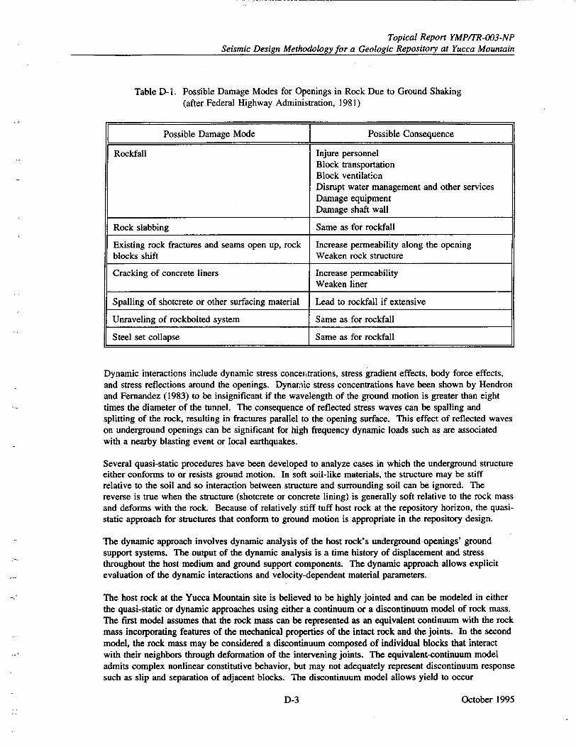
Topical Report YMP/TR-003-NP Seismic Design Methodology for a Geologic Repository at Yucca Mountain
Table D-1. Possible Damage Modes for Openings in Rock Due to Ground Shaking (after Federal Highway Administration, 1981)
Possible Damage Mode J Possible Consequence
Rockfall Injure personnel Block transportation Block ventilation Disrupt water management and other services Damage equipment Damage shaft wall
Rock slabbing Same as for rockfall
Existing rock fractures and seams open up, rock Increase permeability along the opening blocks shift Weaken rock structure
Cracking of concrete liners Increase permeability Weaken liner
Spalling of shotcrete or other surfacing material Lead to rockfall if extensive
Unraveling of rockbolted system Same as for rockfall
Steel set collapse Same as for rockfall
Dynamic interactions include dynamic stress conceittrations, stress gradient effects, body force effects, and stress reflections around the openings. Dynamic stress concentrations have been shown by Hendron and Fernandez (1983) to be insignificant if the wavelength of the ground motion is greater than eight times the diameter of the tunnel. The consequence of reflected stress waves can be spalling and splitting of the rock, resulting in fractures parallel to the opening surface. This effect of reflected waves on underground openings can be significant for high frequency dynamic loads such as are associated with a nearby blasting event or local earthquakes.
Several quasi-static procedures have been developed to analyze cases in which the underground structure either conforms to or resists ground motion. In soft soil-like materials, the structure may be stiff relative to the soil and so interaction between structure and surrounding soil can be ignored. The reverse is true when the structure (shotcrete or concrete lining) is generally soft relative to the rock mass and deforms with the rock. Because of relatively stiff tuff host rock at the repository horizon, the quasistatic approach for structures that conform to ground motion is appropriate in the repository design.
The dynamic approach involves dynamic analysis of the host rock's underground openings' ground support systems. The output of the dynamic analysis is a time history of displacement and stress throughout the host medium and ground support components. The dynamic approach allows explicit evaluation of the dynamic interactions and velocity-dependent material parameters.
The host rock at the Yucca Mountain site is believed to be highly jointed and can be modeled in either the quasi-static or dynamic approaches using either a continuum or a discontinuum model of rock mass. The first model assumes that the rock mass can be represented as an equivalent continuum with the rock mass incorporating features of the mechanical properties of the intact rock and the joints. In the second model, the rock mass may be considered a discontinuum composed of individual blocks that interact with their neighbors through deformation of the intervening joints. The equivalent-continuum model admits complex nonlinear constitutive behavior, but may not adequately represent discontinuum response such as slip and separation of adjacent blocks. The discontinuum model allows yield to occur
October 1995D-3
Topical Report YMP/TR-003-NP Seismic Design Methodology for a Geologic Repository at Yucca Mountain
anisotropically or along specified structters -within .the' ,Ak. taxs. 1B0toi riasses of models permit
inclusion of various levels of complexity, -For example.h, tteqi•val.t-•onti••,ium models range from a
simple elastic model to a more complex compliant jeint ,model (SNL, i)9_7z Chen, 1990).
D.2 EMPIRICAL METHODS
Empirical methods are used to evaluate the impact of the ranges of expected natural conditions on drift
stability and ground support requirements. General purpose methods can be augmented by specific case
studies of excavations either in tuff or similar rock subjected to loads within the range expected for the
repository. Together, these provide a basis for engineering judgment and development of rules of thumb
(heuristic rules) that might apply to repository design.
Generally, empirical methods are developed by relating key parameters that affect stability to the
support used in existing tunnels and caverns. Empirical techniques are useful in repository design to
accomplish the following:
"* Quantify rock quality by an index* that combines different characteristics of a rock mass
"* Assess stability of a given opening span either by indicating the estimated stand-up time or by
indicating for what span ground support is required
* Conduct preliminary assessment of ground support requirements for a given size opening
* Estimate rock mass mechanical properties such as rock mass modulus and strength.
Empirical methods for ground support/rock reinforcement design are presented by Terzaghi (1946);
Deere et al., (1966); Wickham et al., (1972); Barton et al., (1974); and Bieniawski (1973, 1976, 1979).
Einstein et al., (1979) provide a useful discussion of the development of empirical methods and compare
the predictive capability of the above five methods with actual experience in a number of well
documented tunnels, and conclude that none of the methods completely represent all the influencing
factors.
The Barton rock mass quality (Q) method (Barton et al., 1974) and the rock mass rating method
(Bieniawski, 1973, 1976, 1979) both contain six rock parameters related to joint frequency: number of
joint sets, water conditions, joint roughness, joint alteration, intact rock strength, and stress. The main
difference between the two methods is that the stress state is not explicitly considered in the rock mass
rating method, whereas the discontinuity attitude is. In the Q method, the stress reduction factor
accounts for the ratio of the in situ stress field to the rock strength. This parameter can be used to
account for additional thermal and seismic loads in drift design (Barton, 1984).
Using the Q system requires an estimate of Q, the opening span, and the excavation support ratio. The
equivalent dimension is defined as the span divided by the excavation support ratio. By plotting the Q
versus the equivalent dimension on the design chart shown in Figure 6-6, the type of support, if any,
can be determined. Barton et al., (1974) provide specific details on the recommended support for 38
regions on their design chart (not shown here) and also provide methods to estimate the roof and wall
support pressures.
Several modifications of the rock mass rating system have been proposed to account for factors that
were not included in the original formulation (such as induced stress and construction methods). The
modified basic rock mass rating, proposed by Cummings et al., (1982, p. 195) and Kendorski et al.,
(1983), was developed specifically for block caving mines and introduces factors specific to that
application; it indicates a method of incorporating stress change, construction method (in the format of a
factor related to blast damage), and fracture orientation into this empirical method.
October 1995 D-4

Topical Report YMP/TR-003-NP Seismic Design Methodology for a Geologic Repository at Yucca Mountain
Hoek (1981) and Laubscher (1984) have both related ground support selection and mechanisms of failure to the relationship between the rock mass strength and the local state of stress around the drift. Where the design rock mass strength is high relative to the local stress, no failure is predicted; hence, no ground support is required. Alternatively, where the local stress is high relative to the design rock mass strength, stress-induced failures can occur requiring ground support. Figure D-1 (from Hoek, 1981) indicates where stress-induced failure or structurally controlled failures would be predicted and general ground support required for ranges of rock quality and stress/strength ratio. The design rock mass strength of Laubscher (1984) is estimated from the laboratory rock strength modified by a factor developed from the rock mass rating, and further reduced by factors representing weathering, blasting damage, and joint orientation. These methods are a little more appealing than the Q and rock mass rating methods because they correlate support needs with the stress-to-strength relationships around the opening. An approach specifically tailored for tunnel boring machine excavation was proposed by Lauffer (1988). This approach requires the inputs of rock mass rating and supported span to determine the adequate ground support components for installation.
The approaches of Hock (1981) and Laubscher (1984) form the basis of an empirical scheme proposed by Schmidt (1987) to identify the modes of failure around a drift. This method is based on the stress-to-strength relationship and a rock-quality index (a modified rock quality designation). Figure 6-5 shows the regions on the plot of stress/strength ratio versus modified rock quality designation where particular modes of failure are projected. With the mode of failure established, analytical techniques that specifically address that mode of failure can be selected and a ground support system designed to effectively control the rock failure.
TUNNEUNG QUALITY INDEX Q 0.001 0.01 0.1 1.0 4 10 40 100 400 1000 0 111 1 1a I1 0
STRUCTURALLY 01- CONTROLLED
FAILURE GENERALLY 0.1
0.2 - NO SUPPORT 0.2 UIGHT
0.3 -RT 0.3
0.4 -MEDIUMA 04SUPPORT 0.4
-0 HEAVY -0.5
0.6 -Pt PWSOFSUPPORT
06 MAXIMM 0.6
-1 07 I f M NOT0. 0.7 - •/PRACTICAL - 0.7 I kp TO MAINTAIN 0.8
00 8STABLE OPENINGS SRESS 0.
0.9 - INDUCED 09 J FAILURE 0.9
1.0 fI 1.0 0 10 20 30 40 50 60 70 80 90 100 ""IIII I
VERYOOR P OOR I FAIR I GOOD VERYG'i'
ROCK MASS RATINGS RMR
Figure D-1. Approximate Guidelines for Underground Excavations Proposed by Hock (1981)
October 1995D-5
Topical Report YMP/TR-003-NP Seismic Design Methodology for a Geologic Repository at Yucca Mountain
A criticism of empirical techniques in applying them to repository design is that case studies upon which they are based do not include the conditions expected at the repository site, nor do they incorporate some of the important thermal and seismic loads expected during the life of the repository. In the Q system (Barton, 1984), the thermal or seismic loads can be incorporated by combining the induced loads and treating this value as an in situ load. A similar approach could be used with the modified basic rock mass rating system where the thermal and seismic loads are equated to the stress change induced by mining. The former procedures are recommended for assessing preliminary ground support requirements under the thermal and seismic loads.
A first indication of the potential impact of seismic loads can be obtained from empirical evidence of damage in underground openings following a seismic event. Case studies compiled by Dowding and Rozen (1978) (see Figure D-2) suggest that no damage should be expected if the peak surface accelerations are less than 0.2 g, and only minor damage should be experienced between 0.2 and 0.4 g. The "minor damage" described by Dowding and Rozen (1978) included "fall of stones and formation of new cracks." Such occurrences would not disrupt waste-transport operations nor performance of emplacement drifts, and may be tolerable if inspections and maintenance of underground openings are planned. Various criteria for the onset of damage in terms of peak particle velocities for earthquake and explosion from a number of studies were collected by Owen and Scholl (Federal Highway Administration, 1981) and are presented in Figure D-3. A limiting factor in applying this empirical evidence to other situations is that neither the stability conditions of the underground opening before the seismic event nor the design basis of the ground support systems is shown for the cases included in the study.
In summary, all empirical systems inadequately account for the combined effects of in situ, thernial, and seismic loadings, thus necessitating the need for more detailed analyses of the drift stability and the interaction of the support/reinforcement components. In the preliminary design stages, the results of the empirical design should provide classification of the expected in situ conditions into groups for analysis; identification of the potential failure mechanisms that should be addressed analytically; and identification of shapes or loading that, in combination with specific in situ conditions, would pose constructibility problems and could indicate regions where wastes should not be emplaced.
D.3 QUASI-STATIC APPROACH
The quasi-static approach is based on the assumption that history and inertia effects are small and that the significant effects of a seismic event can be represented by quasi-static stress change or strain imposed on the rock structure. If an opening exists in the rock structure, the effect of the seismic event on the stability of the opening can be analyzed using appropriate linear and nonlinear rock models that incorporate either directly or indirectly the influence of jointing and rock mass characteristics. In the quasi-static approach, the seismic loads are based on the estimated ground accelerations and ground velocities of the site; these loads are combined with the in situ and thermal loads to assess opening stability. Within the repository, some drifts will be located away from the heat sources so that in situ and seismic loads will dominate the stability design. Alternatively, at the emplacement drifts where the thermal loads will be high, the in situ and seismic loads will be of relatively lesser importance. The design methods will be partially validated during prototype testing during the site characterization phase, but because the seismic and thermal loads are not easily reproduced in a short time frame, extensive field testing and extrapolation to the repository scale will be required.
October 1995 D-6
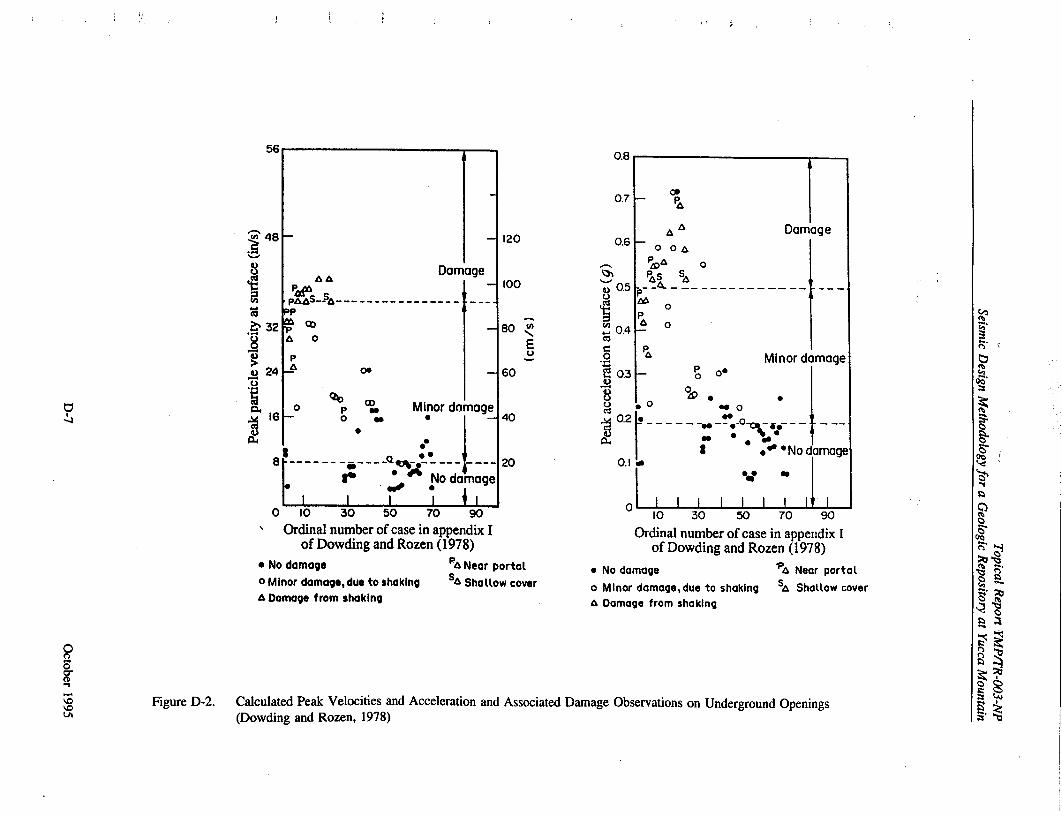
. 48
0
CA
. 32
S24
1.6
0 10 30 50 70
Ordinal number of case in ap of Dowding and Rozen (I
e No damage * Minor damage, due to shaking
A Damage from shaking
U13
0.7
120
100
-80 E
-60
damage 40
.. . .20
i damage
90 'pendix I 1978)
PA Near portal SA Shallow cover
0.6
G) 0.5
0.4
0
"E 0.3
0.2
0.1
* Nod
o Min
�J.
10 30 50 70 90
Ordinal number of case in appendix I of Dowding and Rozen (1978)
damage 'PA Near portal
or damage,due to shaking Sh Shattow covera Damage from shaking
Figure D-2. Calculated Peak Velocities and Acceleration and Associated Damage Observations on Underground Openings (Dowding and Rozen, 1978)
-,4
00
Damage 0 OA
o
0 A o I
Pa Minor damage P0 00
0 0
00
t *No damage
I I I I I I I~ I
-N
0'0
(.b..
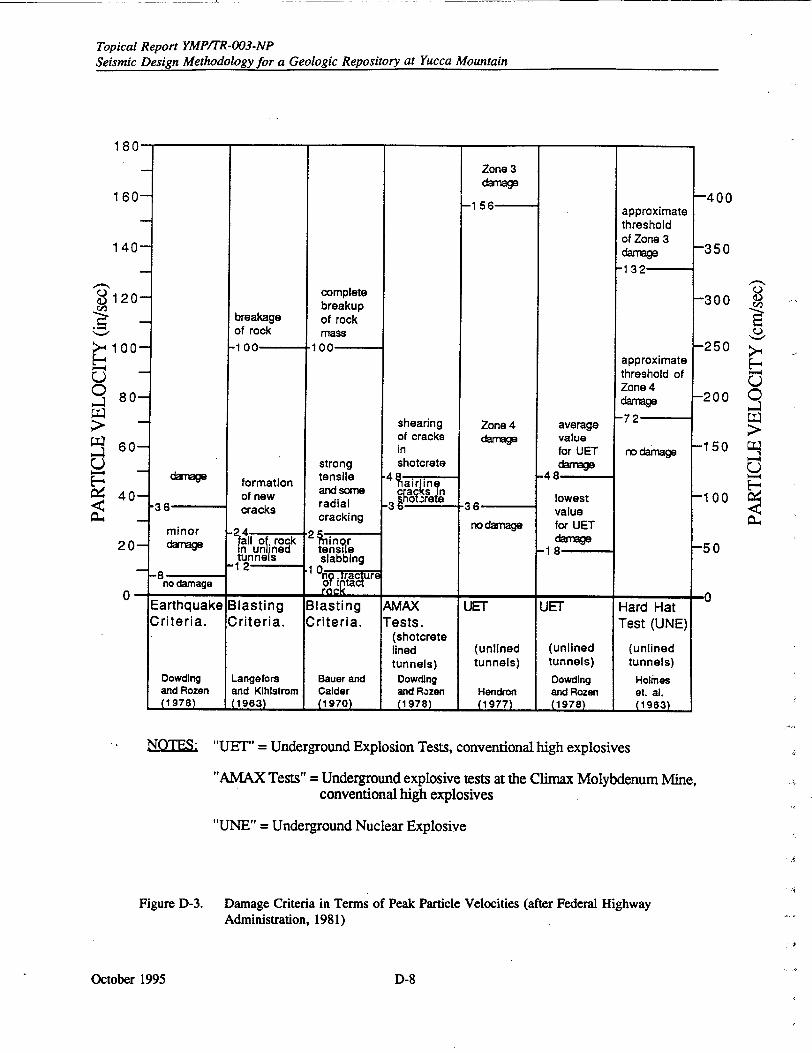
Topical Report YMPITR-003-NP Seismic Design Methodology for a Geologic Repository at Yucca Mountain
*I. I I I *I* I
breakage of rock
-1 00
formation of new cracks
jall of. rock in unlined tunnels I
-12
complete breakup of rock mass
100
strong tensile and some radial cracking
'2 ninor tensile slabbing
fno trfacture or iQltact
shearing of cracks in shotcrete
"4ir Ing c0ac sR -39 notzrelen
Zone 3 damage
-1 56
Zone 4 damage
"-36 nodamage
average value for UET damage
-48
lowest value for UET damage
-1i8
approximate threshold of Zone 3 damage
-132
approximate threshold of Zone 4 damage
-72
no damage
0120
>-• 100
U 9o ,-180
W 60U
40
20
0-Blasting Criteria.
Bauer and Calder (1970)
AMAX Tests.
(shotcrete lined tunnels)
Dowding and Rozen (1978)
UET
(unlined tunnels)
Hendron (1977)
UET
(unlined tunnels)
Dowding and Rozen (1978)
Hard Hat Test (UNE)
(unlined tunnels)
Holmes et. a]. (1983)
Earthquake JBlasting Criteria. ICriteria.
Langefors and Kihistrom (1I g3•
NOTES: "UET" = Underground Explosion Tests, conventional high explosives
"AMAX Tests" = Underground explosive tests at the Climax Molybdenum Mine, conventional high explosives
"UNE" = Underground Nuclear Explosive
Figure D-3. Damage Criteria in Terms of Peak Particle Velocities (after Federal Highway Administration, 1981)
October 1995
160
140-
9 P 4. b I
-400
-350
-300
-250
-200 0
-150 U
U
-100
-50
-A
minor damage
-8 no damage
Dowdling and Rozen (19781
D-8
I I I I I I It I • E(19 631( 1 963i
".36 -
Topical Report YMP/TR-003-NP Seismic Design Methodology for a Geologic Repository at Yucca Mountain
D.3.1 Numerical Analysis for Quasi-Static Approach
Numerical techniques have developed along with the increase in computer hardware capabilities and are now in widespread use in analysis of underground openings subject to in situ, thermal, and changing loads resulting from mining adjacent areas. These methods, traditionally used for static analysis, have been used to support design by empirical methods and to evaluate relatively unusual loading conditions or adverse geologic conditions.
Modeling of jointed rock masses generally follows two approaches, commonly known as equivalentcontinuum and discontinuum methods. The first model assumes that the rock mass can be represented as an equivalent-continuum with the constitutive model for the rock incorporating features of the mechanical properties of the intact rock (matrix) and the joints. In the second model, the rock mass may be considered a discontinuum composed of individual blocks which interact with their neighbors through elastic and plastic deformation of the intervening joints. In practical terms, the former model may admit complex nonlinear constitutive behavior, but may not adequately represent discontinuum response such as slip and separation of adjacent rock blocks. The latter model allows yield to occur anisotropically or along specified structures within the rock mass-for example, sliding of a wedge into an opening-but this method becomes unrealistic when the number of fractures becomes large and the characteristic fracture spacing becomes small relative to the size of the modeled domain. The type of approach to be used is a function of the scale of the problem (i.e., relation of spacing of discontinuities to excavation size), the intact rock and joint properties, and the field stresses.
Models range from simple, elasto-plastic continuum models wherein the elastic modulus for the rock mass incorporates a reduction factor to reflect jointing, to more complex ubiquitous-joint models. Ubiquitous-joint models are based on a continuum description of a rock mass containing joints where the joint spacings are small relative to the scale of the opening of interest. Elastic models for jointed materials are presented by Morland (1974), Singh (1973), and Gerrard (1982); and nonlinear formulations incorporating compliant joint and yielding along joint surfaces are proposed by Thomas (SNL, 1982), Chen (1990; SNL, 1987), and Blanford and Key (SNL, 1990b).
Joint properties are incorporated into the ubiquitous-joint models. Joint mechanical responses are extremely varipble depending on joint surface topography, infill materials, deformation history, and fluid conditions. Barton (Office of Nuclear Waste Isolation, 1982) provides a comprehensive review of joint behavior.
The shear and normal stiffness of discontinuities can exert a controlling influence on the distribution of stresses and displacements within a discontinuous rock mass. Conditions for slip on major pervasive features such as faults or for the sliding of individual blocks from the boundaries of excavations are governed by the shear strengths that can be developed by the discontinuities concerned.
The discontinuum method explicitly models joints as discontinuities in the intact matrix rock. Here the precise location and orientation of the joint or j,.int sets is modeled with the mechanical response characterized by the models discussed above. Discontinuum models include those models that incorporate discrete joints or discontinuities in otherwise continuum models" or block models, i.e., UDEC (Cundall, 1971 and 1980), DECIDE (Pande et al., 1990), and discontinuous deformation analysis methods of Shi (1990). The block models start from the assumption that the rock mass is composed of blocks that can interact with each other. An assemblage of blocks can then represent a jointed rock mass. Blocks can rotate and/or move relative to each other, but cannot move through another block. The motion at intersections or along interfaces between two blocks is controlled by joint stiffness and strength parameters. The discontinuous models can incorporate various nonlinear joint models to simulate slip along the interfaces. Some models incorporate deformable blocks while others assume that all deformability is localized to the joints or block interfaces. Although these models can simulate dynamic processes, they have, to date, primarily been applied to quasi-static problems for repository
October 1995D-9
Topical Report YMP/TR-003-NP Seismic Design Methodology for a Geologic Repository at Yucca Mountain
design because dynamic analysis models have not been adequately validated. The complete deformation
process leading to instability can be modeled, including block splitting and block fallout. Ground
support components can be added to stabilize the opening. Application of these models to dynamic
problems is discussed further in Section D.4, Dynamic Analysis.
Both the continuum and discontinuum models have application in the repository design at hard-rock
repository sites. The application and utility of either method depends on the nature of the rock mass
and the scale of the problem of interest. Figure 6-3 illustrates the influence of scale on the selection of
an appropriate jointed rock model. Regional studies to evaluate. the overall effect of the heating of the
rock on stresses or deformations, for example, at shaft or ramp access locations, require a regional rock
model and, generally, a continuum model can be used. For localized drift design, the decision to
discretely model joints depends on the joint spacings relative to the opening dimensions, and to some
extent, on the knowledge of the joint pattern, continuity, and mechanical characteristics. Figure 6-4
shows a logic flow diagram of how to select the appropriate jointed rock model for drift design
analyses.
Several codes incorporating equivalent-continuum models are available. These include the compliant
joint model (SNL, 1987a) which is incorporated into the finite-element JAC code (SN-L, 1984), the joint
empirical model by Blanford and Key (SNL, 1990b), and FLAC, a finite difference code (Itasca, 1993).
These models incorporate joint normal and shear stiffnesses and the joint spac',g to determine the
compliance of the rock mass and joint slip, or yield if the joint strength is exceeded.
When the joint spacings are small and the jointing orientation random, then isotropic equivalent
continuum models may be appropriate. These models incorporate isotropic, linearly elastic behavior,
and elastic perfectly-plastic response after yield. For yielding rocks, a non-associated flow rule is
appropriate to limit the dilation that accompanies yielding.
Engineering judgment is required in selecting the rock model and in simplifying the geometries to be
analyzed for design. The seismic wave incidence angle and the rock structure are not necessarily
orthogonal with the drift or shaft axis, so two-dimensional simplification is not precise. At drift
intersections, three-dimensional geometries are inevitable. Nonetheless, most drift and shaft designs are
based on two-dimensional idealization of the loads, structure, and geometries.
Ground support components include rockbolts, rockbolts with straps or wire mesh, shotcrete, steel sets,
and concrete. Combinations of rockbolts with other components are quite common in application of
poorer quality rock or where loads are high in relation to rock strength. Selection of the appropriate
ground support system most often involves empirical schemes as mentioned earlier, but for repository
design, analysis is required to assist in the support selection. As a first approach for selection of ground
support capacities in blocky rock, support loads can be assessed with and without seismic loads using
simple block weights adjusted for seismic acceleration, as discussed by Hendron and Fernandez (1983).
Under the combined seismic and thermal loads for the equivalent continuum, the support components
should be designed conservatively to support the weight of failed or yielded rock. Here again, judgment
is required in defining the terms "failed" or "yielded rock" because slip along joints in and of itself does
not imply unstable conditions, and "failed" rock is often self-supporting. Also, the compatibility of the
ground support components and the imposed loads (due to excavations, seismic events, and thermal
effects) must be assessed. For example, a stiff rockbolt may be incompatible with the deformation of a
soft rock subject to seismic and thermal loads. Such aspects may not be apparent from empirical
designs or from uncoupled analyses.
For all nonlinear quasi-static models, step loadings and cyclic loadings can be applied to evaluate
accumulation of damage or hysteresis effects associated with cyclic dynamic loads.
October 1995 D-10
Topical Report YMP/TR-003-Np Seismic Design Methodology for a Geologic Repository at Yucca Mountain
D.4 DYNAMIC ANALYSIS OF ROCK MASSES
Natural earthquakes, underground nuclear events, rockbursts, etc. are the sources of dynamic ground motion of underground excavations. Differences between the ground motion from these various sources are expressed in terms of the frequency and duration of strong ground motion. Other dynamic effects that may be significant for underground repository facilities are primarily those that may result from equipment failure and similar events. However, whatever the source of the ground motion, the same methods of analysis may be used to predict the performance of dynamically-loaded, underground excavations in jointed rock.
Dynamic analysis differs from quasi-static analysis in that mass-acceleration terms are included in the force equilibrium equation and, in some numerical methodologies, rate dependent properties can be considered. Available analytical solutions for the dynamic equilibrium equations are generally limited to problems involving infinite or semi-infinite elastic media or simple circular openings in elastic media, hence numerical methods are primarily used. Dynamic analysis can be performed using finite element, finite difference, boundary element, and distinct element methodologies.
To date, continuum modeling techniques have been the preferred design procedure for survivability predictions for tunnels subject to dynamic loading. However, in the case of a fractured and jointed rock medium where the discontinuities play a critical role in determining the deformation, the discrete element method provides an important technique for modeling the medium.
Senseny (1993) discusses the success of five dynamic analysis codes in analyzing a benchmark problem simulating an opening in jointed rock subject to a near-surface shock load. Of the five codes, two were distinct block models and three were equivalent continuum models. This discussion highlights the lack of standards in conducting dynamic analysis and difficulties, such as initial stress, absorbing, and non-reflecting boundaries, that are not fully resolved. Further difficulties in continuum representation of jointed media were uncovered in this benchmark exercise.
D.5 MATERIAL PARAMETERS FOR DESIGN
Discussed below are the estimates of rock mass and joint parameters used for design in jointed rock. These material parameters are useful for sites involving strong host rock with unfilled joints. Such conditions are expected for repositories in tuff, but would not be appropriate or complete for repositories in shales or salt where time-dependent deformations may be of concern. The estimates of rock mass properties are based on empirical evidence from the performance of openings underground. The database to support these estimates of rock mass properties is generally poor and somewhat anecdotal. They are not based on seismic loading or dynamic response of the rock mass and are used in quasistatic analysis for design. Modifications for seismic loading or dynamic properties are discussed in Section D.3.
D.5.1 Elastic Modulus
For continuum methods, an equivalent or rock mass modulus must be determined. The rock mass elastic modulus, Et, can be estimated from indices quantifying the rock mass quality. Barton et al., (1980) proposed a rock mass modulus based on the rock mass quality, Q, as follows
E, =40 log10 Q (D-l)
October 1995D-1II
Topical Report YMPITR-003-NP
Seismic Design Methodology for a Geologic Repository at Yucca Mountain
Bieniawski (1979) proposed an algorithm,
E, = 2 RMR-100 (D-2)
where rock mass rating, RMR, is the rock mass rating defined by Bieniawski (1979). Both of these
methods predict unreasonably low rock mass moduli for low quality rock and have a limited range of
applicability. Serafim and Pereira (1983) proposed an algorithm that overcomes this restriction with the
following algorithm
E, = 1 0 (&fR-10)40 (D-3)
All three methods of estimating the rock mass elastic modulus are independent of the elastic modulus of
the intact host rock and assume isotropy.
Zimmerman and Finely (SNL, 1986b) developed a mathematical relationship for representing rock mass
elastic modulus assuming rock mass as layered composite material. The relationship contains both
intact rock properties and joint deformational characteristics.
E& =+ nU.x ] Eo (D-4)
nooU, / (o,+A,)2 + I
where Edt is the tangent modulus of deformation, Eo is the intact rock elastic modulus, n is the number
of joints per unit length, U., is the unstressed joint aperture, A. is the half closure stress, and ca. is the
stress normal to the joint.
D.5.2 Rock Mass Strength
The rock mass strength can similarly be estimated based on rock quality indices and laboratory strength
values. Hoek and Brown (1980) proposed an empirical strength criterion for the rock mass strength, cr,
of the form
oC1% =Cq1o + (ma p%+s)w (D-5)
where m and s are functions of the rock type and rock quality, 0 3 is the confining stress and a1 is the
laboratory derived numerical strength of the intact rock. The expressions for m and s are based on the
rock mass rating for undisturbed or interlocking rock.
m = m• I(M-toa9 (D-6)
and
S = e("R-10ox9 (D-7)
mi is determined from laboratory-scale triaxial compression strength data by fitting laboratory data to
Equation D-5 with s equal to 1.0. Yudhbir et al., (1983) present an alternative method for estimating
rock mass strength based on similar parameters.
October 1995 D-12
Topical Report YMP/TR-003-NP Seismic Design Methodology for a Geologic Repository at Yucca Mountain
Recently, a modified Hoek-Brown failure criterion (Hoek et al., 1992) was developed to reformulate the criterion to eliminate the tensile strength predicted by the original Hoek and Brown criterion and to include a simplified qualitative rock mass classification of the estimation of the parameters. The modified criterion is expressed in the following form
al = (3 + a( b(mb3Aa (D-8)
where mb and a are constants for broken rock.
There are obvious limitations to these equivalent-continuum isotropic models when applied to regularly jointed rock masses. The accuracy of these methods is also unknown because of the lack of definitive correlation between large-scale performance of rock masses and predicted performance based on these models.
D.5.3 Joints
For discontinuum methods, a joint or discontinuity is regarded as a boundary interaction between two blocks, and is not represented as a separate element. All of the discrete element methods allow joints (contacts) to open or slide. Joint properties may be specified with very general force-displacement relationships which are possible in both the normal and shear directions. That means the deformability of the discontinuities or interfaces between blocks and the frictional characteristics are represented by spring-slider systems with prescribed force-displacement relations which allow evaluation of shear and normal forces between blocks.
The joint deformation is characterized by a shear stiffness and a normal stiffness. The shear stiffness is defined as the change of the current state of shear stress with respect to the change in the relative displacement of the joint faces tangential to the plane of the joint. The normal stiffness is defined as the change in the current state of normal stress with respect to the relative displacement of the joint faces normal to the plane of the joint. A joint is said to dilate if it thickens, that is, two intact rock faces increase their separation as shear displacement develops. The dilatancy mechanism stems mainly from surface roughness. Rough blocks, perfectly mating, can be forced to'slide past one another only if they are free to move apart, that is, to move over asperities. However, if the blocks are confined, shearing is possible only through the asperities themselves.
The various discrete element methods treat the behavior of the contact in the normal direction of motion in two different ways: soft contact approach and hard contact approach. In the soft contact approach, a finite normal stiffness is taken to represent the measurable normal stiffness that exists at a contact or on a joint. Measurements on rock joints (Sun et ai., 1985) indicate that the joint normal stiffness is comparable to that of the adjoining rock blocks, at low stress levels. In the hard contact approach, the physical assumption is that no interpenetration c. the two blocks occurs, although shear movement and opening can occur. The task of the numerical scheme is to ensure displacement compatibility in the normal direction at all contacts, while satisfying equilibrium and constitutive laws.
Discontinuum methods require the location, orientation, and geometric and mechanical properties of the discontinuities to be specified. The geometric definition of the joints and joint sets is derived from mapping of the joint traces along exposures (at surface or along drifts and shafts) and from core hole data. Geometric models of the jointing patterns can be developed for geologic units and sub-units depending on the variability of the site. Descriptive terms used to describe the jointed rock mass include joint persistence (the ratio of joint length and joint trace length), joint spacing (the distance between parallel joints), joint orientation or joint set orientations, the number of joint sets, joint lengths, and joint curvature or waviness. The joint roughness, joint infilling, and joint infill thickness and
October 1995D-13
Topical Report YMP/TR-003-NP
Seismic Design Methodology for a Geologic Repository at Yucca Mountain
aperture are descriptions of the individual joints, and influence the mechanical properties of the joint.
All the joint descriptions can be defined specific to a particular location or can be specified statistically.
Significant advances have been made in the description of joint patterns and joint characteristics. See,
for example, Long et al., (1987) and Lee et al., (1990).
The mechanical properties of discontinuities relate the normal and shear forces across the joint to the
normal and shear displacements. The joint mechanical properties are measured in a direct shear test or
triaxial cell. In a conventional shear test, a normal load is applied to a specimen, and the shear
displacement induced by a series of known applied shear stresses is determined. The complete behavior
is determined by repeating the test at different normal stress levels.
The simplest coherent model of joint deformation and strength is the linear deformation, Coulombic
friction model. It is illustrated in Figure D-4. The key features are, for normal loading (Figure D-4a),
elastic reversible closure up to a limiting value Un', and cracking when the normal stress is less than the
joint tensile strength. For shear loading (Figure D-4(b)), shear displacement is linear and reversible up
to a limiting shear stress (determined by the normal stress), and then perfectly plastic. Shear load
reversal after plastic yield is accompanied by permanent shear displacement and hysteresis. The relation
between limiting shear resistance and norrnal stress, shown in Figure D-4c, is typical of Coulombic
friction.
The linear deformation, Coulombic friction joint model may be appropriate fo. smooth discontinuities
which are non-dilatant in shear, such as faults at residual strength. The value of the model is that it is a
useful reference case for joint deformation and strength.
The relation between normal stress and shear strength in the Mohr-Coulomb model, which is a straight
line representation of the shear strength dependence on normal strength, is given by
S= c + a. tan$ (D-9)
where c = cohesion S= joint friction angle.
In a more comprehensive model-the Barton-Bandis model (Office of Nuclear Waste Isolation, 1982;
Barton et al., 19g5)-dilatancy is implicit!y related to surface roughness
S= G, tan[WRC 1o01 0 (JCS/o,) + IN (D- 10)
where JRC = joint roughness coefficient
= residual joint friction angle (Y" = normal stress
JCS = compressive strength of the joint wall rock.
October 1995 D-14
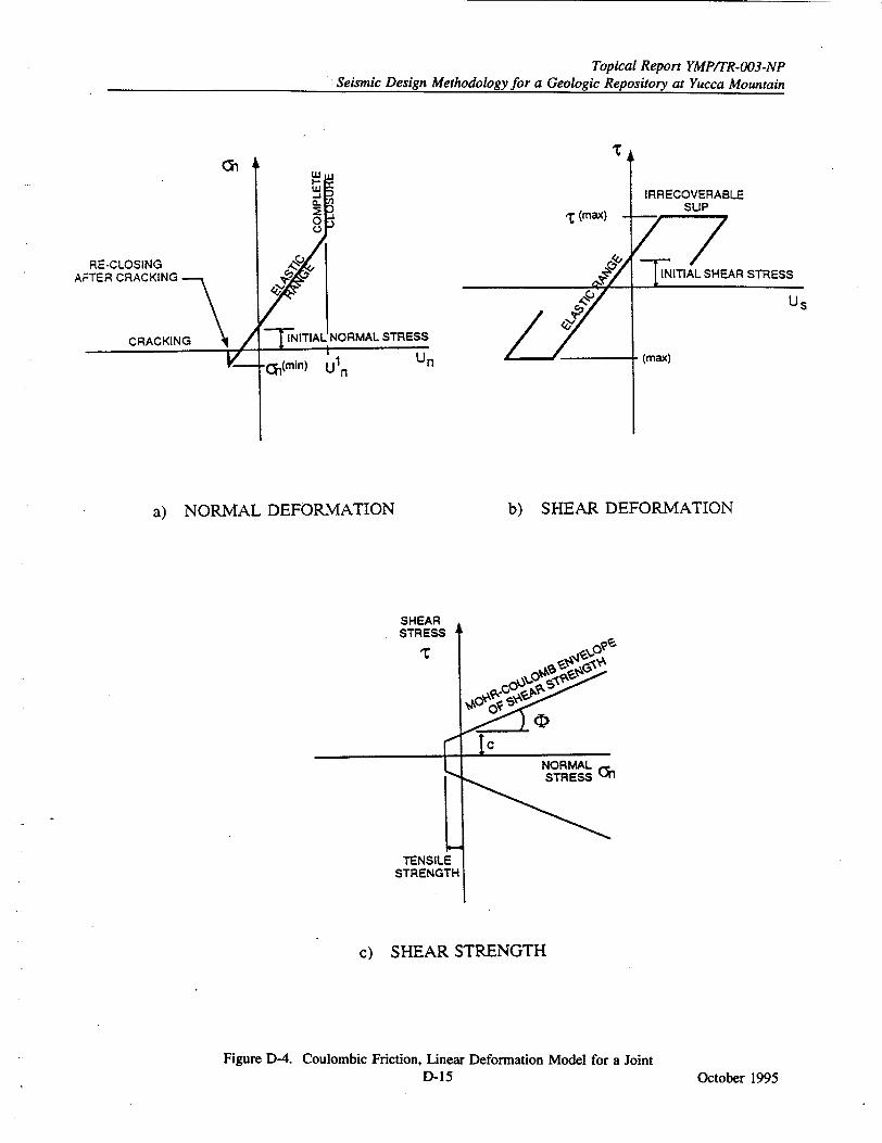
Topical Report YMP/TR-003-NP Seismic Design Methodology for a Geologic Repository at Yucca Mountain
Ch
RE-CLOSING AFTER CRACKING
(max)
STRESS
nin) Uln
IRRECOVERABLE SLIP
Us
(max)
a) NORMAL DEFORMATION
SHEAR STRESS
______________ .4 -
TENSILE STRENGTH
b) SHEAR DEFORMATION
¶olp% ý
go *0 Ic
0NORMAL
C) SHEAR STRENGTH
Figure D-4. Coulombic Friction, Linear Deformation Model for a Joint D-15 October 1995
L
,ncee Gn
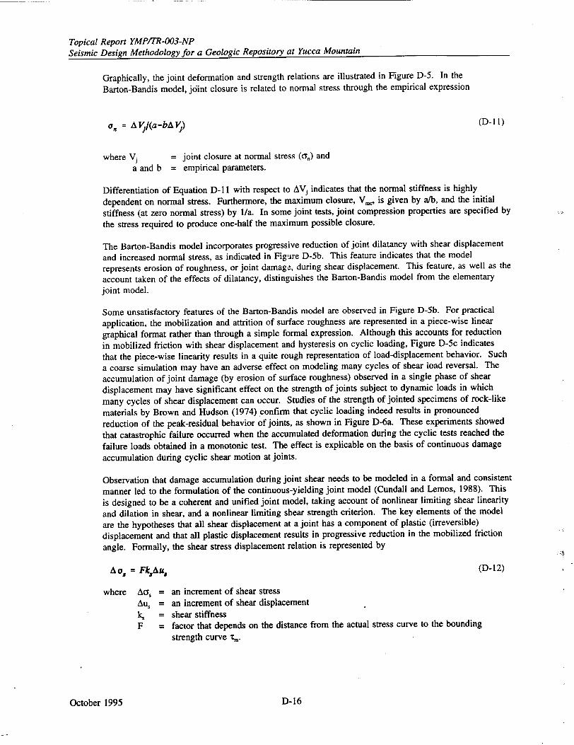
Topical Report YMP/TR-003-NP Seismic Design Methodology for a Geologic Repository at Yucca Mountain
Graphically, the joint deformation and strength relations are illustrated in Figure D-5. In the
Barton-Bandis model, joint closure is related to normal stress through the empirical expression
a', = AVj(a-bAVj,) (D- 11)
where Vj = joint closure at normal stress (can) and a and b = empirical parameters.
Differentiation of Equation D- 11 with respect to AVj indicates that the normal stiffness is highly
dependent on normal stress. Furthermore, the maximum closure, V., is given by a/b, and the initial
stiffness (at zero normal stress) by 1/a. In some joint tests, joint compression properties are specified by
the stress required to produce one-half the maximum possible closure.
The Barton-Bandis model incorporates progressive reduction of joint dilatancy with shear displacement
and increased normal stress, as indicated in Figure D-5b. This feature indicates that the model
represents erosion of roughness, or joint damage, during shear displacement. This feature, as well as the
account taken of the effects of dilatancy, distinguishes the Barton-Bandis model from the elementary joint model.
Some unsatisfactory features of the Barton-Bandis model are observed in Figure D-5b. For practical
application, the mobilization and attrition of surface roughness are represented in a piece-wise linear
graphical format rather than through a simple formal expression. Although this accounts for reduction
in mobilized friction with shear displacement and hysteresis on cyclic loading, Figure D-5c indicates
that the piece-wise linearity results in a quite rough representation of load-displacement behavior. Such
a coarse simulation may have an adverse effect on modeling many cycles of shear load reversal. The
accumulation of joint damage (by erosion of surface roughness) observed in a single phase of shear
displacement may have significant effect on the strength of joints subject to dynamic loads in which
many cycles of shear displacement can occur. Studies of the strength of jointed specimens of rock-like
materials by Brown and Hudson (1974) confirm that cyclic loading indeed results in pronounced
reduction of the peak-residual behavior of joints, as shown in Figure D-6a. These experiments showed
that catastrophic failure occurred when the accumulated deformation during the cyclic tests reached the
failure loads obtained in a monotonic test. The effect is explicable on the basis of continuous damage
accumulation during cyclic shear motion at joints.
Observation that damage accumulation during joint shear needs to be modeled in a formal and consistent
manner led to the formulation of the continuous-yielding joint model (Cundall and Lemos, 1988). This
is designed to be a coherent and unified joint model, taking account of nonlinear limiting shear linearity
and dilation in shear, and a nonlinear limiting shear strength criterion. The key elements of the model
are the hypotheses that all shear displacement at a joint has a component of plastic (irreversible)
displacement and that all plastic displacement results in progressive reduction in the mobilized friction
angle. Formally, the shear stress displacement relation is represented by
A, 5 = FkAu. (D-12)
where Aa, = an increment of shear stress Au, = an increment of shear displacement k, = shear stiffness
F = factor that depends on the distance from the actual stress curve to the bounding
strength curve ,m.
October 1995 D-16
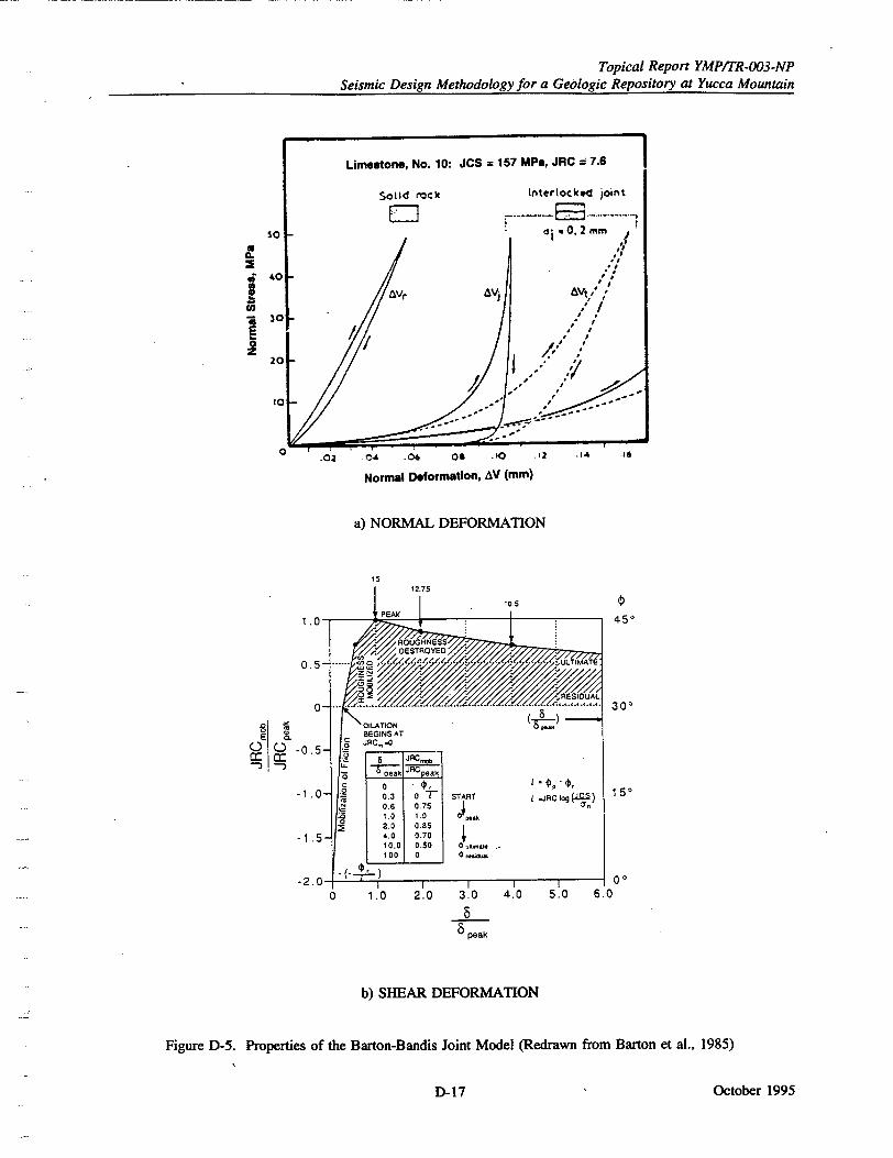
Topical Report YMPfTR-003-NP Seismic Design Methodology for a Geologic Repository at Yucca Mountain
.02 014 .06 011 .10 .'2 IA I6
Normal Deformation, AV (mm)
a) NORMAL DEFORMATION
0.5
0
() -0.5
-1.0
-1.5
-2.00
1 7
1Ei 2.7510.5
I I I I I 1.0 2.0 3.0 4.0 5.0
5 5• peak
b) SHEAR DEFORMATION
Figure D-5. Properties of the Barton-Bandis Joint Model (Redrawn from Barton et al., 1985)
October 1995
0
z
0
45*
30*
15*
0o
S BEGINS AT , JRCý.C!
- 7 e JRCo.a"
Ii I 0 Z I 0.3 0 , START i-JRClog ) 4! i0.6 0.7 4s 8!r .0 1.0 1.0 O ej•k
4.0 0.70
10.0 O.SO 1. 00 0 ,s,
60
D-17
A1
I II
Topical Report YMPITR-003-NP Seismic Design Methodology for a Geologic Repository at Yucca Mountain
JRC mob JRCb JRC peak
+1.0
b ------------- -- #t ..........
Sresidul ry• 0•1
E, 1,3 4
-0.5 - /
-1.0 I /
0=0° ,I e 0 =0°
3 - -1 + - 1 3 4
+1.5 - u-- .-. a
g peak
+0.5o _ __ _ _ 0 • residual
-•G (l) uftimate
01 .0 peak
c) HYSTERESIS ON CYCLIC SHEAR LOADING
Figure D-5. Properties of the Barton-Bandis Joint Model (Continued)
October 1995
0 peak .P
r
D-18
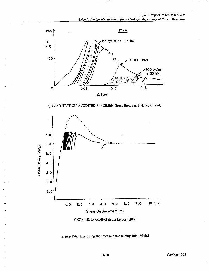
Topical Report YMP/ITR-003-NP Seismic Design Methodology for a Geologic Repository at Yucca Mountain
0 0"05 0"10 0.15
A (cm)
a) LOAD TEST ON A JOINTED SPECIMEN (from Brown and Hudson, 1974)
7.0
5.0
5.0
4.0
3.0
2.0
1.0
I /
1.0 2.0 3.0 4.0 5.0 5.0 7.0 N ,.E-4)
Shear Displacement (m)
b) CYCLIC LOADING (from Lemos, 1987)
Figure D-6. Exercising the Continuous-Yielding Joint Model
October 1995
c.
CL €
W
D-19
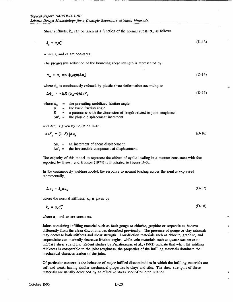
Topical Report YMP/TR-003-NP Seismic Design Methodology for a Geologic Repository at Yucca Mountain
Shear stiffness, k., can be taken as a function of the normal stress, CF., as follows
k, = aac (D-13)
where a. and es are constants.
The progressive reduction of the bounding shear strength is represented by
"T'X = C,, tan .,tsgn(Au) (D-14)
where 0,. is continuously reduced by plastic shear deformation according to
A4m = -I1R (•P-4)AuP. (D-15)
where m = the prevailing mobilized friction angle = the basic friction angle
R = a parameter with the dimension of length related to joint roughness AuP. = the plastic displacement increment.
and AuP, is given by Equation D-16
Aups = (1-F) IAUs (D-16)
Au, = an increment of shear displacement AuPs = the irreversible component of displacement.
The capacity of this model to represent the effects of cyclic loading in a manner consistent with that reported by Brown and Hudson (1974) is illustrated in Figure D-6b.
In the continuously yielding model, the response to normal loading across the joint is expressed incrementally,
AOn = k.Au. (D- 17)
where the normal stiffness, kn, is given by
k. = a~ao (D-18)
where an and en are constants.
Joints containing infilling material such as fault gouge or chlorite, graphite or serpentinite, behave differently from the clean discontinuities described previously. The presence of gouge or clay minerals may decrease both stiffness and shear strength. Low-friction materials such as chlorite, graphite, and serpentinite can markedly decrease friction angles, while vein materials such as quartz can serve to increase shear strengths. Recent studies by Papalioangas et al., (1993) indicate that when the infilling thickness is comparable to the joint roughness, the properties of the infilling materials dominate the mechanical characterization of the joint.
Of particular concern is the behavior of major infilled discontinuities in which the infilling materials are soft and weak, having similar mechanical properties to clays and silts. The shear strengths of these materials are usually described by an effective stress Mohr-Coulomb relation.
October 1995 D-20
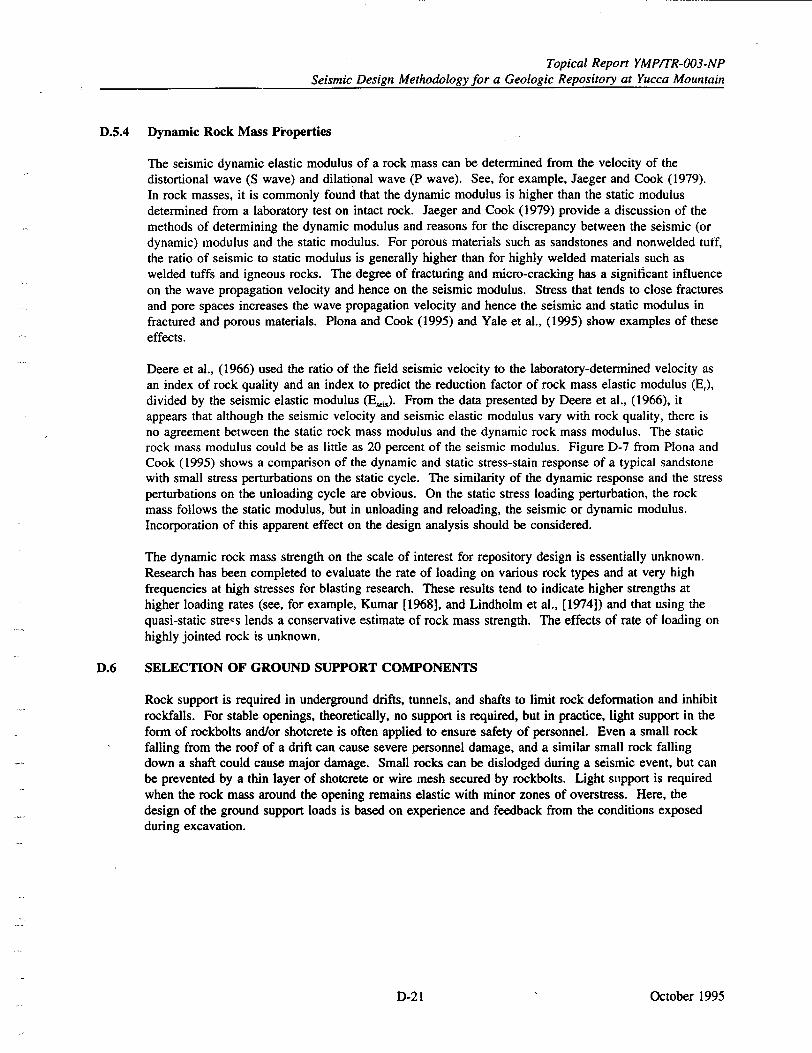
Topical Report YMP/TR-003-NP Seismic Design Methodology for a Geologic Repository at Yucca Mountain
D.5.4 Dynamic Rock Mass Pioperties
The seismic dynamic elastic modulus of a rock mass can be determined from the velocity of the distortional wave (S wave) and dilational wave (P wave). See, for example, Jaeger and Cook (1979). In rock masses, it is commonly found that the dynamic modulus is higher than the static modulus determined from a laboratory test on intact rock. Jaeger and Cook (1979) provide a discussion of the methods of determining the dynamic modulus and reasons for the discrepancy between the seismic (or dynamic) modulus and the static modulus. For porous materials such as sandstones and nonwelded tuff, the ratio of seismic to static modulus is generally higher than for highly welded materials such as welded tuffs and igneous rocks. The degree of fracturing and micro-cracking has a significant influence on the wave propagation velocity and hence on the seismic modulus. Stress that tends to close fractures and pore spaces increases the wave propagation velocity and hence the seismic and static modulus in fractured and porous materials. Plona and Cook (1995) and Yale et al., (1995) show examples of these effects.
Deere et al., (1966) used the ratio of the field seismic velocity to the laboratory-determined velocity as an index of rock quality and an index to predict the reduction factor of rock mass elastic modulus (Er), divided by the seismic elastic modulus (Ei). From the data presented by Deere et al., (1966), it appears that although the seismic velocity and seismic elastic modulus vary with rock quality, there is no agreement between the static rock mass modulus and the dynamic rock mass modulus. The static rock mass modulus could be as little as 20 percent of the seismic modulus. Figure D-7 from Plona and Cook (1995) shows a comparison of the dynamic and static stress-stain response of a typical sandstone with small stress perturbations on the static cycle. The similarity of the dynamic response and the stress perturbations on the unloading cycle are obvious. On the static stress loading perturbation, the rock mass follows the static modulus, but in unloading and reloading, the seismic or dynamic modulus. Incorporation of this apparent effect on the design analysis should be considered.
The dynamic rock mass strength on the scale of interest for repository design is essentially unknown. Research has been completed to evaluate the rate of loading on various rock types and at very high frequencies at high stresses for blasting research. These results tend to indicate higher strengths at higher loading rates (see, for example, Kumar [1968], and Lindholm et al., [1974]) and that using the quasi-static stre-s lends a conservative estimate of rock mass strength. The effects of rate of loading on highly jointed rock is unknown.
D.6 SELECTION OF GROUND SUPPORT COMPONENTS
Rock support is required in underground drifts, tunnels, and shafts to limit rock deformation and inhibit rockfalls. For stable openings, theoretically, no support is required, but in practice, light support in the form of rockbolts and/or shotcrete is often applied to ensure safety of personnel. Even a small rock falling from the roof of a drift can cause severe personnel damage, and a similar small rock falling down a shaft could cause major damage. Small rocks can be dislodged during a seismic event, but can be prevented by a thin layer of shotcrete or wire mesh secured by rockbolts. Light support is required when the rock mass around the opening remains elastic with minor zones of overstress. Here, the design of the ground support loads is based on experience and feedback from the conditions exposed during excavation.
October 1995D-21
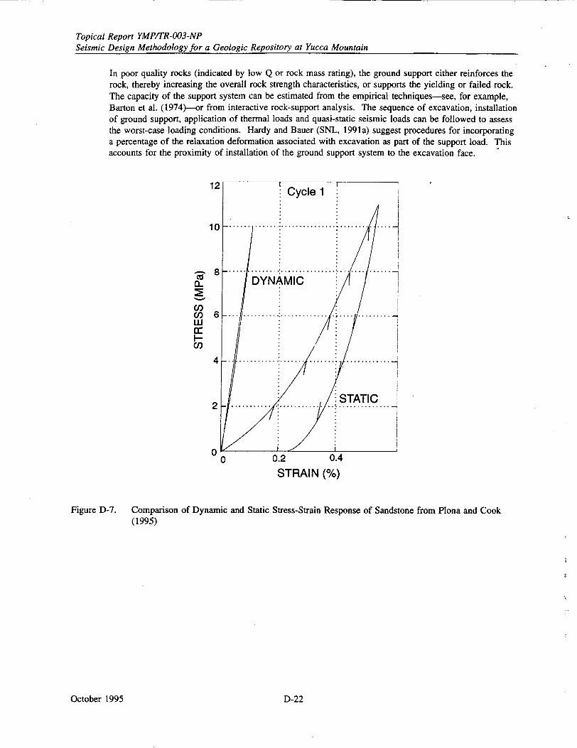
Topical Report YMP/TR-003-NP Seismic Design Methodology for a Geologic Repository at Yucca Mountain
In poor quality rocks (indicated by low Q or rock mass rating), the ground support either reinforces the rock, thereby increasing-the overall rock strength characteristics, or supports the yielding or failed rock. The capacity of the support system can be estimated from the empirical techniques-see, for example, Barton et al. (1974)--or from interactive rock-support analysis. The sequence of excavation, installation of ground support, application of thermal loads and quasi-static seismic loads can be followed to assess the worst-case loading conditions. Hardy and Bauer (SNL, 1991a) suggest procedures for incorporating a percentage of the relaxation deformation associated with excavation as part of the support load. This accounts for the proximity of installation of the ground support system to the excavation face.
12 Cycle 1
1 0 .. .... ............................:
8 . i ... ... IL DYNAMIC
Co 6 . w
Ul) .. .. . .
00 0.2 0.4
STRAIN (%)
Figure D-7. Comparison of Dynamic and Static Stress-Strain Response of Sandstone from Plona and Cook (1995)
October 1995 D-22
Topical Report YMP/TR-003-NP Seismic Design Methodology for a Geologic Repository at Yucca Mountain
APPENDIX E
EXAMPLES OF TUNNEL DESIGN AND PERFORMANCE THROUGH FAULTS
October 1995E-1
Topical Report YMP/TR-003-NP Seismic Design Methodology for a Geologic Repository at Yucca Mountain
APPENDIX E
EXAMPLES OF TUNNEL DESIGN AND PERFORMANCE THROUGH FAULTS
This appendix reviews case histories of tunnels that have been, or may potentially be, subjected to earthquake-induced fault displacement. Although the database is limited and consists mainly of transportation and water tunnels, the cases provide information for the design of proposed underground facilities at Yucca Mountain, as discussed in Section 9. Many of these cases, up to about the end of the 1970s, were reviewed and presented by Brown et al., (U.S. Department of Transportation, 1981). Most examples are of civil tunnels along the coast of California and in Japan, a geographic bias that apparently reflects the frequent coincidence of active faults and civil structures in those regions. A few examples are given of the support of deep African mine tunnels subjected to induced seismicity.
Fault displacement in most of the case histories is due to rupture during an earthquake, although a few cases are given where fault creep is the primary source of movement. Emphasis in this review is on reporting the manner of faulting and the extent of damage to the structure. In addition, design and construction methods used for dealing with potential displacement are discussed.
E.1 EXAMPLES FROM NORTHERN CALIFORNIA
E.1.1 Southern Pacific Railroad Tunnel, Santa Clara County
An 1890 m long Southern Pacific Railroad tunnel extends through the Santa Cruz Mountains and crosses the San Andreas fault near Wright Station. Damage to the tunnel by movement along the San Andreas fault during the 1906 San Francisco earthquake is discussed by Louderback (1950) and Brown et al., (U.S. Department of Transportation, 1981). The San Francisco earthquake is estimated to have had a magnitude of 8.25. Associated with the earthquake, a right-lateral displacement of 1.4 m occurred along a shear zone intersecting the tunnel about 120 m from the northeast portal. During reconstruction, a survey found that horizontal displacement of the tunnel decreased from this maximum offset near one end to zero about 1500 m further into the tunnel. Damage in the vicinity of the maximum offset included crushing of timber supports, heaving of rails, and rock fall. Some railroad ties were broken in the middle. Other shear zones of similar orientation had minor offsets and at the ground surface immediately above the tunnel, larger displacements were found along the San Andreas fault trace than were observed underground. At present the tunnel is closed, although apparently it remains functional, since a current study is considering the feasibility of using the tunnel for a commuter rail line (Looking at Reviving Line, 1994).
E.1.2 San Andreas Dam Overflow Tunnel, Santa Clara County
During the 1906 San Francisco earthquake, fault displacement occurred in ground forming the left abutment of the San Andreas dam. A 2.1 to 2.4 m diameter overflow tunnel with 432 mm thick brick and concrete walls was cut in two by the fault movement. The fault displacement at the tunnel was 1.5 m, and the tunnel was "badly crushed" for 8.5 m at its outlet end (Louderback, 1950, pp 147). No mention is made of repair or reconstruction.
E.1.3 Coyote Dam Outlet Tunnel, Santa Clara County
Frame (1995) describes a lining design for the tunnel outlet at the Coyote Dam on Coyote Creek. Coyote Dam is an earthfill dam constructed in 1935 to 1936 and operated by the Santa Clara Valley Water District. Modifications, completed in 1991, included the construction of a new water outlet tunnel approximately 215 m long and 3 m in diameter to replace an existing outlet endangered by siltation. The tunnel, excavated through sandstone, conglomerate, and shale, passes through a potentially active fault zone composed of clayey gouge which is considered to be a splay of the nearby Calaveras fault. Although the tunnel has experienced no fault rupture, the Calaveras fault has an overall slip rate
October 1995 E-2
Topical Report YMP/TR-003-Np Seismic Design Methodology for a Geologic Repository at Yucca Mountain
of about 15 mm per year and is considered the source of historic earthquakes, the maximum of which was a magnitude 6.6 event that occurred in 1911.
The outlet tunnel has a reinforced concrete lining. A 56 m long section of the lining was designed to .cope with potential movement along the fault zone by the use of articulated joints at 3 m centers. Each joint has been constructed to withstand 0.3 m of fault displacement in any direction without failure of the lining. Some features of this construction are 1) the concrete joint itself which is formed as an open joint to allow movement, 2) sealant in the joint and a PVC waterstop across the joint to prevent water penetration, and 3) reinforcing bars installed with bond breakers to permit longitudinal slip along the bars.
E.1.4 Berkeley Hills Tunnels, Alameda and Contra Costa Counties
The four tunnels discussed below are all affected by fault creep on the Hayward fault. Fault creep has been defined by Burford et al. in a 1978 U. S. Geological Survey publication (U.S. Department of Transportation, 1981) as "gradual, aseismic slip that is apparently produced by viscous yielding within a relatively weak fault gouge." The word "slippage" is considered by Brown et al., (ibid.) to be the more appropriate term since "creep" refers to the material behavior phenomenon of plastic flow under a sustained load. However, fault creep is used herein since the term is less ambiguous.
E.1.4.1 Bay Area Rapid Transit Tunnels, Alameda County
In the San Francisco Bay Area, the Bay Area Rapid Transit twin tunnels pass through the Berkeley Hills. The tunnels were constructed in 1967 and are 4950 m long, 30 m apart, and have an inside diameter of 5.3 m. They have about 70 m of cover where they cross the Hayward Fault near the west portal. The behavior of the tunnels due to fault creep on the Hayward Fault since construction in 1967 has been examined and evaluated in detail by Brown et al., (ibid.). Survey data and observations have indicated that fault creep of 6 to 8 mm a year is associated with a shear zone about 215 m wide.
During tunnel excavation in the Hayward Fault zone, squeezing ground broke support timbers and distorted steel sets, even though invert struts were used on 610 mm centers. As a consequence, a substantial supporting structure was installed at the fault zone, resulting in a relatively stiff tunnel section. Consideration of long-term rock loads led to a circular section for the final tunnel lining, although a horstLshoe-shaped tunnel was initially excavated. A drainage system was included to reduce possible long-term hydrostatic loading.
Neither the circular lining section nor the drainage system specifically pertained to a seismic design. However, in consideration of fault offset potential, Brown et al., (ibid.) state that "It was also considered desirable to have a flexible lining; consequently, the final lining was kept as thin as practicable (457 mm)." Longitudinal reinforcement steel was added, presumably for added strength. Although it is stated, "... to accommodate possible movement along the Hayward Fault during an earthquake, a tunnel section larger than that required for the operation of BART trains was constructed ... ." other reasons, having to do with rolling stock clearances, are given for actually having an inside radius larger than that used in other parts of the system. Also, sufficiently large fault displacements (design displacements of "two feet horizontal and one foot vertical") were believed to be accommodated with no change in the designed tunnel radius if fault movement were distributed over about 100 m of tunnel rather than on a single plane. For these reasons, it is doubtful the tunnel was ever constructed with an enlarged section just for the purpose of accommodating fault displacement.
October 1995E-3
Topical Report YMPITR-003-NP Seismic Design Methodology for a Geologic Repository at Yucca Mountain
Of particular interest since fault creep on the Hayward Fault is now well documented, is that fault creep
along the Hayward Fault was not considered at the time of design of the Bay Area Rapid Transit
tunnels. During construction this aspect of fault behavior was brought to the attention of the designers,
and the track was laid on wooden ties to allow future realignment. At the same time it was decided to
instrument the section of the northern tunnel where it crosses the Hayward Fault (ibid.).
E.1.4.2 Claremont Tunnel, Alameda County
The Claremont tunnel example is similar to that of the Bay Area Rapid Transit tunnels, the west portals
of which are located 245 m south of the Claremont Tunnel. The Claremont tunnel was constructed just
prior to 1929 to transport water through the Berkeley Hills to the east side of the San Francisco Bay.
The tunnel is 5507 m long and has a horseshoe-shaped cross section about 2.74 m high and 2.74 m
wide. Most of the tunnel is lined with unreinforced concrete at least 355 mm thick, where placed over
initial timber supports, and 300 mm thick where untimbered. Heavy timber and reinforced concrete
were used in some sections, especially where squeezing ground was encountered. The tunnel crosses
the Hayward Fault near the west portal. A 1964 inspection found that the concrete lining in the fault
zone was cracked and the invert was buckled. A survey determined that 168 mm of right lateral offset
had occurred since construction. In respon ;e to the fault related damage, the tunnel section in the Hayward Fault was relined.
E.1.4.3 San Pablo Tunnel, Contra Costa County
The San Pablo tunnel was constructed between 1917 and 1920 to transport water from the San Pablo
reservoir through the Berkeley Hills to the east side of the San Francisco Bay. The tunnel is 4134 m
long and in cross section is 2.29 m high and 2.44 m wide. The tunnel crosses two major active fault
zones, the Hayward and the Wildcat, as well as several unnamed faults. The Hayward Fault was
encountered during construction at a depth between 70 and 100 m. The fault zone material was
described as serpentine that was so sheared that it flowed into the tunnel under its own weight and was
difficult to control.
Repairs and inspections made between construction and the late 1970's demonstrate the continuous
nature of the deformation to which the tunnel has been subjected. In 1933 a major break occurred at a
distance between 625 and 687 m from the west portal near the Hayward Fault crossing. A heavily
reinforced concrete lining was constructed at that location to repair the tunnel. From 1952 to 1953, the
tunnel invert was replaced and a new lining constructed inside the existing lining. During inspection in
1969, a circumferential crack was noted at 981 m and longitudinal cracks were seen at 1945 m and
2015 m. Inspection in 1978 found apparent horizontal distortion between 2637 and 2652 m.
E.2 EXAMPLES FROM SOUTHERN CALIFORNIA
E.2.1 Southern Pacific Railroad Tunnels, Kern County
In 1952, the Arvin-Tehachapi earthquake of magnitude 7.7 resulted from reverse or thrust fault
movement on the White Wolf Fault (Kupfer et al., 1955). The earthquake severely damaged 18 km of
railroad of the Southern Pacific Company at Tehachapi Pass. Fault displacements, presumably
associated with an extension of the White Wolf Fault, occurred during the earthquake and affected four
tunnels along the railroad. Major damage occurred to the tunnels with portions collapsed and
alignments distorted. Descriptions and interpretations of the fault damage are taken from Kupfer et al.,
(ibid.) and from Brown et al., (U.S. Department of Transportation, 1981).
A zone of faulting and fracturing from 150 to 210 m wide intersected two of the tunnels approximately
at right angles. Bowed up tracks and ground shortening of about 3 m indicated local compression
across the zone and evidence for reverse fault movement. The most extensive damage to the tunnels
was the buckling and cracking of sidewalls. Normal faulting, which occurred after the initial reverse
October 1995 E-4
Topical Report YMP/TR-003-NP Seismic Design Methodology for a Geologic Repository at Yucca Mountain
fault movement, was minor although normal faults in two tunnels produced vertical offset up to about a meter. The tunnels were less than 60 m deep in highly weathered granitic rock. In addition, they were close to the side of a valley, which may have resulted in locally affecting tunnel damage.
The tunnels were initially timber-lined, then later relined with 300 to 600 mm of reinforced concrete placed over the original wood lining. Reinforcing steel was concentrated along the intrados. According to Kupfer et al., (1955), there was a marked contrast between observed characteristics of the surface fault zone and the zone seen in the tunnels. In the tunnels the zone was about 150 m wide and the damage was severe. On the surface, in general, fractures were few and small, and displacements were less than 300 mm.
Reconstruction involved replacing portions of the concrete linings in some tunnels where cave-ins had occurred and making extensive portal repairs. However, the solution to much of the remedial work that was required was the complete reconstruction of the damaged tunnels as open cuts.
E.2.2 Balboa Inlet Tunnel, San Fernando Valley
This example is presented essentially as reported by Brown et al., (U.S. Department of Transportation, 1981). The partially completed Balboa Inlet Tunnel of the Metropolitan Water District of Southern California was affected by the San Fernando earthquake (magnitude 6.6) of 1971. Displacement occurred along the Santa Susanna Thrust Fault, which crossed the tunnel about 300 m from a portal. The reinforced concrete liner was cracked and there was some spalling along a 90 m section at the fault crossing. In addition, longitudinal cracking occurred in the tunnel liner for about 300 m on each side of the fault. The Santa Susanna Fault had been inactive since the middle Pleistocene and was not considered related to the active faults that produced the San Fernando earthquake. Movement along the Santa Susanna Fault was thus considered a response to stress changes on the nearby active fault system.
E.2.3 North Outfall Replacement Sewer Tunnel, City of Los Angeles
This description of design features of the North Outfall Replacement Sewer is from an article by Desai, Merritt, and Chang (1989). The tunnel, as designed, is 12.6 km long with inside diameters varying from 2.9 to 3.75 m. Known faults crossing the alignrment include splays of the active (displacement within the last 11,000 years) Newport-Inglewood fault zone, and the potentially active (displacement during the last 2 million years) Overland Avenue and Charnock faults. In consideration of tunnel design to accommodate fault movements, lateral fault displacements were considered to range from 200 to 450 mm and vertical displacements were estimated at half the lateral values.
The concept used in the tunnel design is to surround a conduit, placed within the tunnel, with a low modulus backpacking. The conduit is protected because the backpacking provides a much greater potential for compliance between the conduit and the natural medium than would be the case with an ordinary lining system, and allows for discrete offset to occur in the surrounding medium without imposing a discrete displacement on the pipe and limits both lateral and longitudinal forces imposed on the enclosed conduit.
An important step in the development of such a tunnel design scheme through a fault zone is the delineation of the actual zone of fault movement. Other considerations have to do with thickness and properties of the backpacking and design of pipe joints and their location relative to the fault location. The tunnel designers used segmented precast pipes with joints having specially configured neoprene seals to accommodate relatively high rotational, extensional, and compressional strains.
October 1995E-5
Topical Report YMPITR-003-NP Seismic Design Methodology for a Geologic Repository at Yucca Mountain
E.2.4 Aqueduct Tunnels, Northern and Southern California
There are a number of water transmission tunnels between the Sierra Nevada and the San Francisco Bay
Area and between the Colorado River and the Los Angeles area that pass through active faults.
Although there were apparently no design measures to cope with potential fault displacement, additional
water storage near the pipeline terminuses and multiple water lines were believed to provide adequate
contingency and redundancy in the system (Louderback, 1950, pp. 149). Whether these measures are
adequate 45 years later is the subject of current evaluations by the affected California municipalities.
E.3 EXAMPLES FROM JAPAN
Yoshikawa and Fukuchi (1984) report on a survey by Yoshikawa of 124 cases of tunnel damage due to
five earthquakes that occurred between 1923 and 1978. The "Richter magnitudes" of these earthquakes
ranged from 7.0 to 7.9. Only in the two cases given below did significant damage occur due to fault
movement. Fault-related damage apparently occurred within 10 km of the earthquake "epicentral zone,"
so-called because the epicenter was defined along a reach of the fault rather than at a point.
E.3.1 Inatori Tunnel
Yoshikawa and Fukuchi (1984) and Brown et al., (U.S. Department of Transportation, 1981) discuss
earthquake damage to the Inatori tunnel. In 1978, the "Near-Oshima" earthquake with a surface wave
magnitude of MK 6.8 produced a I m right-lateral offset on a fault intersecting the tunnel. The zone of
surface rupture associated with this earthquake varied from 30 m to 200 m wide and was traced for 3
km. Maximum displacement was 1.83 m right lateral and 260 mm dip slip on a steeply dipping fault.
The Inatori railroad tunnel crossed the fault at a right angle and had a cover of 90 m. The tunnel was
displaced right-laterally 500 to 700 mm. The tunnel was constructed with a thick, nearly circular (4.8 m
diameter) concrete lining and invert section designed to deal with ground described as fractured, volcanic, and clayey. Although severely distorted, the tunnel did not collapse. It was determined that
the liner apparently was extended 200 mm longitudinally relative to the surrounding rock over a distance
of 120 m. Concrete buckled and fell from the crown, and sections of the sidewall were pushed into the
tunnel. The tunnel was restored by removing part of the existing lining and replacing it with a concrete
lining heavily reinforced with steel bars and steel fibers.
E.3.2 Tanna Tunnel and New Tanna Tunnel
Yoshikawa and Fukuchi (1984) and Brown et al., (U.S. Department of Transportation, 1981) discuss
earthquake damage to the Tanna tunnel. During the 1930 Kita-Izu earthquake, with an estimated
magnitude of 7.1, left-lateral displacement of 2.7 m and vertical displacement of 0.6 m occurred along a
shear zone at the working face of a drainage drift for the Tanna tunnel. Fault displacement at the
ground surface, 160 m above the invert, was somewhat less, with a left-lateral component of 1.0 m and
a vertical component of 0.5 m. Displacement in the tunnel was along the Tanna fault that happened to
coincide with the face, and as a result the drainage drift was completely closed. However, the only
damage to the main tunnel, which was about 0.5 m east of the shear zone, was cracks in the tunnel walls.
The New-Tanna tunnel, constructed "more than 20 years ago" (Yoshikawa and Fukuchi, 1984) in the
vicinity of the Tanna tunnel, also intersected the Tanna fault. Design measures included a thicker lining
and invert than the first Tanna tunnel. Based on an assessment that estimated a return period of 1,000
years for earthquakes on the Tanna fault, the Japanese National Railways decided no additional design
measures were needed.
October 1995 E-6
Topical Report YMPITR-003-NP Seismic Design Methodology for a Geologic Repository at Yucca Mountain
E.4 EXAMPLES FROM SOUTHERN AFRICA
Deep metal mines in Africa often experience mining-induced seismicity which results in rockbursts that jeopardize personnel safety and damage tunnels. Because of the potentially sudden and large displacements involved in these seismic events, flexible ground support systems have evolved. An example is the rock reinforcement used in a deep gold mine in Zambia (Russell et al., 1983). In this case, tunnels and other mined openings in rock have been maintained with a unique system of fully grouted steel dowels (rockbolts), wire mesh, and steel cable "lacing" stretched across the tunnel walls in a diamond pattern between the dowels. During large ground movement this structural system provides sufficient supporting pressure to confine the rock mass, thereby maintaining its self-supporting capacity.
An example of the performance of a bolt/mesh/lacing support system is from a gold mine in South Africa (Brady and Brown, 1985, p. 289) which describes the response of a 1540 m deep haulage tunnel to a 4.0 magnitude seismic event on a fault penetrated by the tunnel. The tunnel, perhaps 4 to 5 m in diameter, was reinforced with 2.5 m long grouted steel rope tendons and 7.5 m long prestressed rock anchors. In addition, mesh and hoist rope lacing was applied to the surface of the opening. The rock was highly fractured as a result of the seismic event, several prestressed anchors failed, and closure of as much as a meter appears to have taken place. However, the damaged rock was adequately contained and the tunnel remained open.
E.5 CONCLUSIONS
Regarding tunnel design, in most of the case histories there were no design provisions to accommodate fault displacement. In tunnels constructed prior to about the 1950s, designers ignored or were unaware of the potential for fault-related damage. When damage occurred, the common approach was to make repairs, with the usual result being a stiffer supporting structure than was in place at the time of fault displacement. Another approach, used in the case of the shallow tunnels at Tehachapi Pass in Kern County (Section E.2.1), included partial or total reconstruction of some of the damaged tunnels as open cuts.
More recent approaches to tunnel fault displacement design have evaluated the necessity for accommodating fault displacement and if necessary have provided flexibility to allow deformation without undue disruption of the tunnel function. One example of this methodology is the North Outfall Replacement Sewer tunnel (Section E.2.3), which proposes an internal conduit or carrier pipe surrounded by a low-modulus material that is intended to sustain and distribute potential fault displacement. Another example is the flexible joint used in the Coyote Dam outlet tunnel (Section E.1.3).
October 1995E-7

Topical Report YMP/TR-003-NP Seismic Design Methodology for a Geologic Repository at Yucca Mountain
INTENTIONALLY LEFT BLANK
*1
October 1995 E-8
Topical Report YMP/TR-003-NP Seismic Design Methodology for a Geologic Repository at Yucca Mountain
APPENDIX F
EXAMPLE APPLICATIONS OF SEISMIC DESIGN METHODOLOGY
October 1995F-1
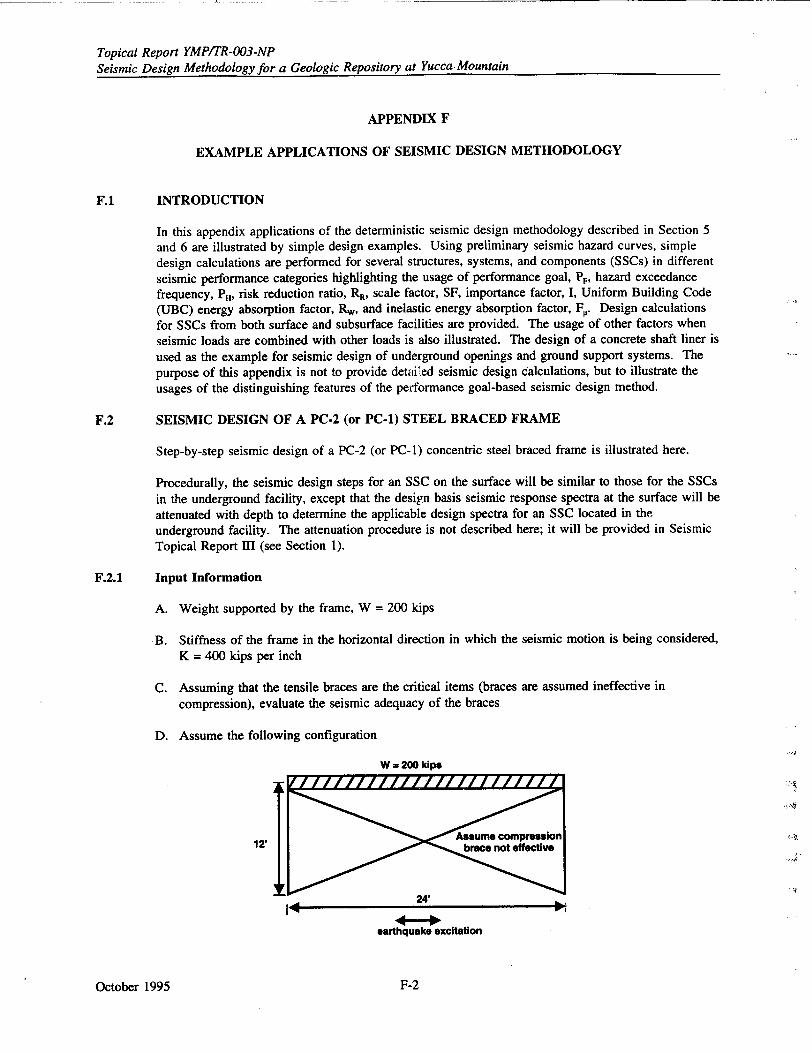
Topical Report YMP/TR-003-NP Seismic Design Methodology for a Geologic Repository at Yucca Mountain
APPENDIX F
EXAMPLE APPLICATIONS OF SEISMIC DESIGN METHODOLOGY
F.1 INTRODUCTION
In this appendix applications of the deterministic seismic design methodology described in Section 5 and 6 are illustrated by simple design examples. Using preliminary seismic hazard curves, simple design calculations are performed for several structures, systems, and components (SSCs) in different seismic performance categories highlighting the usage of performance goal, Pr, hazard exceedance frequency, P, risk reduction ratio, RR, scale factor, SF, importance factor, I, Uniform Building Code (UBC) energy absorption factor, Rw, and inelastic energy absorption factor, F,. Design calculations for SSCs from both surface and subsurface facilities are provided. The usage of other factors when seismic loads are combined with other loads is also illustrated. The design of a concrete shaft liner is used as the example for seismic design of underground openings and ground support systems. The purpose of this appendix is not to provide detaiu'ed seismic design calculations, but to illustrate the usages of the distinguishing features of the performance goal-based seismic design method.
F.2 SEISMIC DESIGN OF A PC-2 (or PC-l) STEEL BRACED FRAME
Step-by-step seismic design of a PC-2 (or PC-1) concentric steel braced frame is illustrated here.
Procedurally, the seismic design steps for an SSC on the surface will be similar to those for the SSCs
in the underground facility, except that the design basis seismic response spectra at the surface will be attenuated with depth to determine the applicable design spectra for an SSC located in the underground facility. The attenuation procedure is not described here; it will be provided in Seismic Topical Report mI (see Section 1).
F.2.1 Input Information
A. Weight supported by the frame, W = 200 kips
B. Stiffness of the frame in the horizontal direction in which the seismic motion is being considered, K = 400 kips per inch
C. Assuming that the tensile braces are the critical items (braces are assumed ineffective in compression), evaluate the seismic adequacy of the braces
D. Assume the following configuration
W = 200 kips
12' Assume compression
24'
earthquake excitation
October 1995 F-2
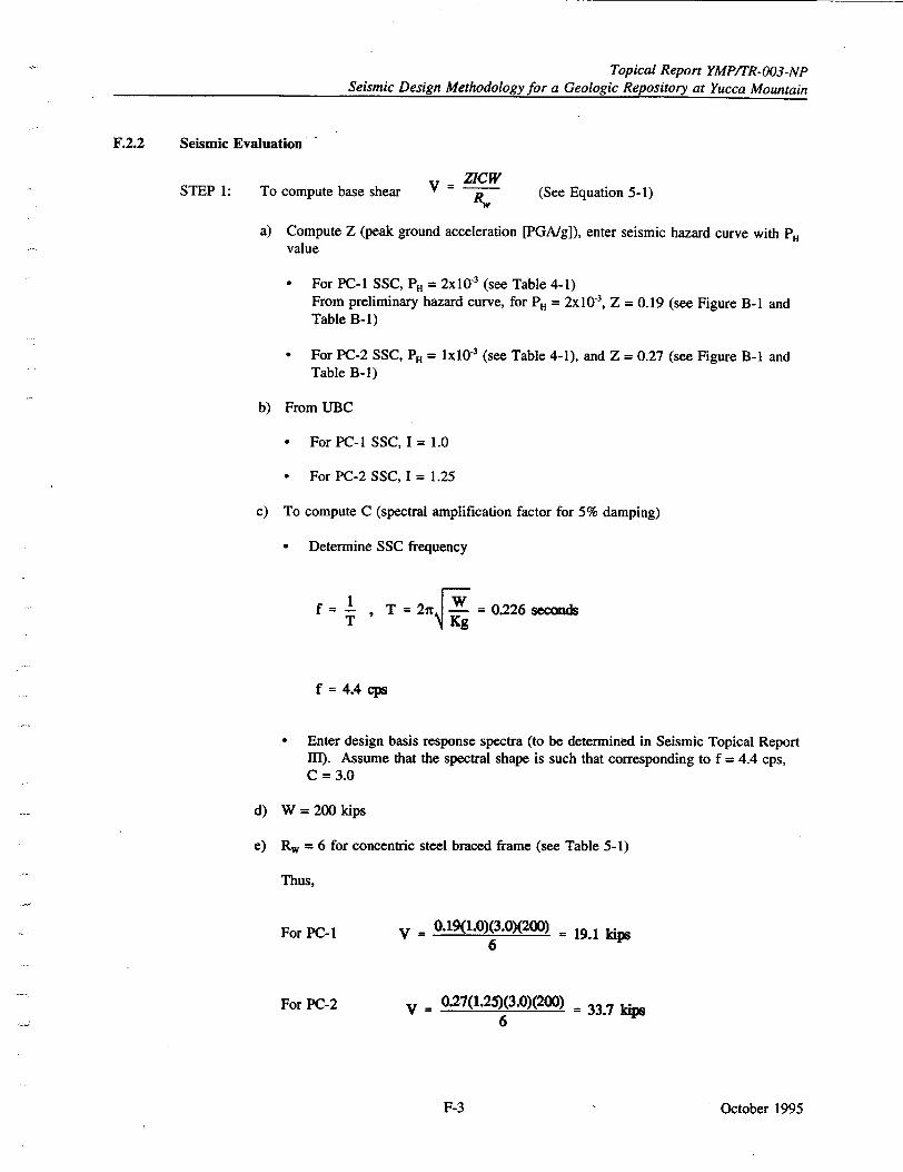
Topical Report YMP/TR-003-NP Seismic Design Methodology for a Geologic Repository at Yucca Mountain
F.2.2 Seismic Evaluation
STEP 1: To compute base shear V ZICW R. (See Equation 5-1)
a) Compute Z (peak ground acceleration [PGA/g]), enter seismic hazard curve with PH value
"* For PC-I SSC, PH = 2x10 3 (see Table 4-1) From preliminary hazard curve, for PH = 2x I03, Z = 0.19 (see Figure B-I and Table B-I)
"* For PC-2 SSC, PH = lx10"3 (see Table 4-1), and Z = 0.27 (see Figure B-1 and Table B-1)
b) From UBC
"* For PC-I SSC, I = 1.0
"* For PC-2 SSC, I = 1.25
c) To compute C (spectral amplification factor for 5% damping)
"* Determine SSC frequency
T = T = 2xZ = 0.226 seconds
f = 4.4 cps
"* Enter design basis response spectra (to be determined in Seismic Topical Report MU). Assume that the spectral shape is such that corresponding to f = 4.4 cps, C = 3.0
d) W = 200 kips
e) Rw = 6 for concentric steel braced frame (see Table 5-1)
Thus,
For PC- I
For PC-2
V = 0.19(1.0)(3.0)(200) = 19.1 kips 6
V = 0.27(1.25)(3.0)(200) = 33.7 kips 6
October 1995F-3
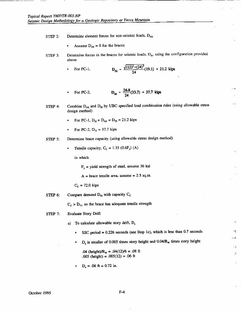
Topical Report YMPITR-003-NP Seismic Design Methodology for a Geologic Repository at Yucca Mountain
STEP 2: Determine element forces for non-seismic loads, DNs
Assume DNS = 0 for the braces
STEP 3: Determine forces in the braces for seismic loads, Ds,, using the configuration provided
above
"• For PC-I, DR= (12)2+(24)2 (19. 1) = 21.2 kips 24
"* For PC-2, Ds = 26'(33.7) = 37.7 kips
STEP 4: Combine DNs and Ds, by UBC specified load combination rules (using allowable stress
design method)
• For PC-I, Ds1+ DNs = Da = 21.2 kips
* For PC-2, D, = 37.7 kips
STEP 5: Determine brace capacity (using allowable stress design method)
• Tensile capacity, Cc = 1.33 (0.6Fy) (A)
in which
FY= yield strength of steel, assume 36 ksi
A = brace tensile area, assume = 2.5 sq.in.
Cc = 72.0 kips
STEP 6: Compare demand DT with capacity Cc
Cc > D,, so the brace has adequate tensile strength
STEP 7: Evaluate Story Drift
a) To calculate allowable story drift, D.
"* SSC period = 0.226 seconds (see Step 1c), which is less than 0.7 seconds
"* D, is smaller of 0.005 times story height and 0.04/Rw times story height
.04 (height)/Rw = .04(12)/6 = .08 ft
.005 (height) = .005(12) = .06 ft
"* D• = .06 ft = 0.72 in.
October 1995 F-4
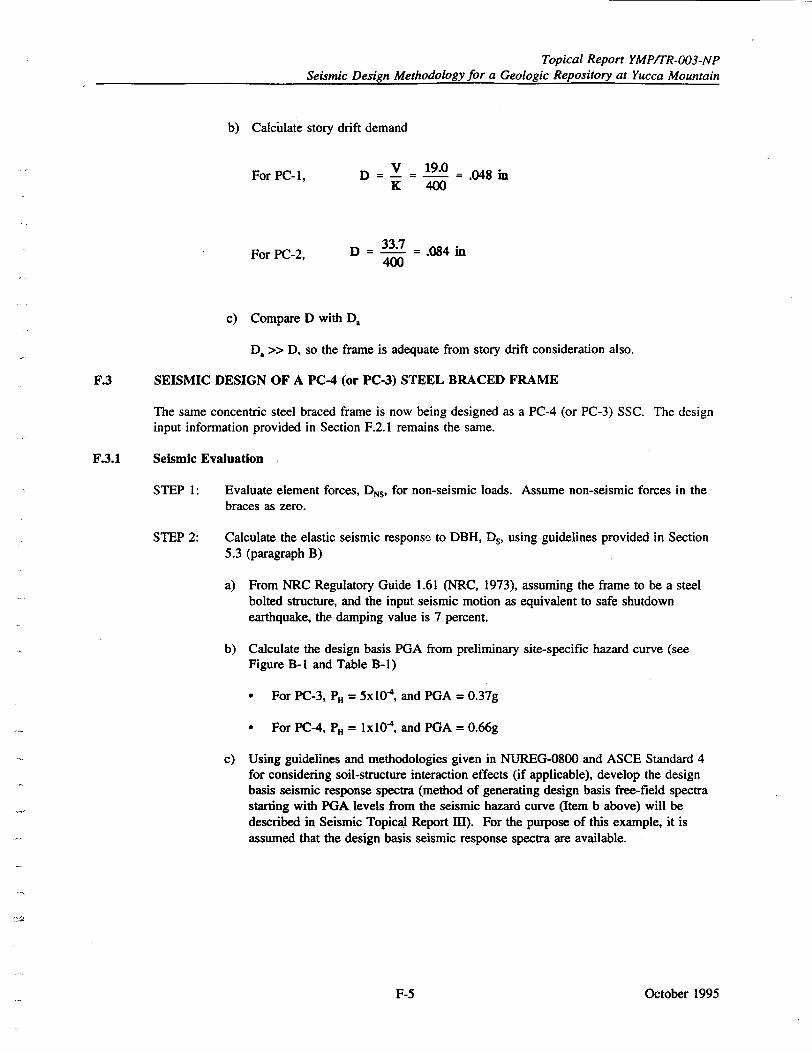
Topical Report YMP/TR-003-NP Seismic Design Methodology for a Geologic Repository at Yucca Mountain
b) Calculate story drift demand
V 19.0= 08i For PC-1, D =- I = 19.0 .048in K 400
For PC-2, D = 33.7 = .084 in 400
c) Compare D with Da
Da >> D, so the frame is adequate from story drift consideration also.
F.3 SEISMIC DESIGN OF A PC-4 (or PC-3) STEEL BRACED FRAME
The same concentric steel braced frame is now being designed as a PC-4 (or PC-3) SSC. The design input information provided in Section F.2.1 remains the same.
F.3.1 Seismic Evaluation
STEP 1: Evaluate element forces, DNs, for non-seismic loads. Assume non-seismic forces in the braces as zero.
STEP 2: Calculate the elastic seismic response to DBH, Ds, using guidelines provided in Section 5.3 (paragraph B)
a) From NRC Regulatory Guide 1.61 (NRC, 1973), assuming the frame to be a steel bolted structure, and the input seismic motion as equivalent to safe shutdown earthquake, the damping value is 7 percent.
b) Calculate the design basis PGA from preliminary site-specific hazard curve (see Figure B-1 and Table B-I)
"* For PC-3, PH = 5x10 4 , and PGA = 0.37g
"* For PC-4, PH = lx10 4 , and PGA = 0.66g
c) Using guidelines and methodologies given in NUREG-0800 and ASCE Standard 4 for considering soil-structure interaction effects (if applicable), develop the design basis seismic response spectra (method of generating design basis free-field spectra starting with PGA levels from the seismic hazard curve (Item b above) will be described in Seismic Topical Report Ill). For the purpose of this example, it is assumed that the design basis seismic response spectra are available.
October 1995F-5
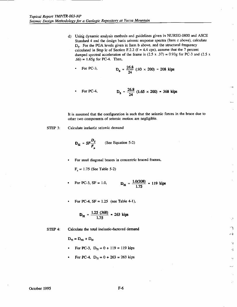
Topical Report YMP/TR-003-NP Seismic Design Methodology for a Geologic Repository at Yucca Mountain
d) Using dynamic analysis methods and guidelines given in NUREG-0800 and ASCE Standard 4 and the design basis seismic response spectra (Item c above), calculate Ds. For the PGA levels given in Item b above, and the structural frequency calculated in Step Ic of Section F.2.2 (f = 4.4 cps), assume that the 7 percent damped spectral acceleration of the frame is (2.5 x .37) = 0.93g for PC-3 and (2.5 x .66) = 1.65g for PC-4. Then,
"* For PC-3,
" For PC-4,
26.8 Ds 26.8 (.93 x 200) = 208 ldps
_ 26___8 (1.65 x 200) = 368 kips D -24
It is assumed that the configuration is such that the seismic forces in the brace due to other two components of seismic motion are negligible.
STEP 3: Calculate inelastic seismic demand
Ds1 = SF.s FT (See Equation 5-2)
* For steel diagonal braces in concentric braced frames,
F, = 1.75 (See Table 5-2)
a For PC-3, SF = 1.0, = 1.0(208) = 119 kp 1.75
* For PC-4, SF = 1.25 (see Table 4-1),
DSI = 1.25 (368) - 263 kips 1.75
STEP 4: Calculate the total inelastic-factored demand
D-n = DNs + Ds,
"* For PC-3, D, = 0 + 119 = 119 kips
"* For PC-4, D- = 0 + 263 = 263 kips
October 1995 F-6
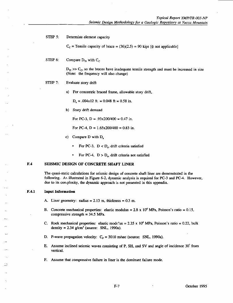
Topical Report YMPITR-003-NP Seismic Design Methodology for a Geologic Repository at Yucca Mountain
STEP 5: Determine element capacity
Cc = Tensile capacity of brace = (36)(2.5) = 90 kips [0 not applicable]
STEP 6: Compare D-, with Cc
D, >> Cc, so the braces have inadequate tensile strength and must be increased in size (Note: the frequency will also change)
STEP 7: Evaluate story drift
a) For concentric braced frame, allowable story drift,
Da = .004x12 ft. = 0.048 ft - 0.58 in.
b) Story drift demand
For PC-3, D = .93x200/400 = 0.47 in.
For PC-4, D = 1.65x200/400 = 0.83 in.
c) Compare D with D.
"* For PC-3, D < Da, drift criteria satisfied
"* For PC-4, D > Da, drift criteria not satisfied
F.4 SEISMIC DESIGN OF CONCRETE SHAFT LINER
The quasi-static calculations for seismic design of concrete shaft liner are demonstrated in the following. As illustrated in Figure 6-2, dynamic analysis is required for PC-3 and PC-4. However, due to its complexity, the dynamic approach is not presented in this appendix.
F.4.1 Input Information
A. Liner geometry: radius = 2.13 m, thickness = 0.3 m.
B. Concrete mechanical properties: elastic modulus = 2.8 x 10⁴ MPa, Poisson's ratio = 0.15, compressive strength = 34.5 MPa.
C. Rock mechanical properties: elastic modv'us = 2.35 x 10' MPa, Poisson's ratio = 0.22, bulk density = 2.34 g/crm3 (source: SNL, 1990a).
D. P-wave propagation velocity: C, = 3010 m/sec (source: SNL, 1990a).
E. Assume inclined seismic waves consisting of P, SH, and SV and angle of incidence 30* from vertical.
F. Assume that compressive failure in liner is the dominant failure mode.
October 1995F-7
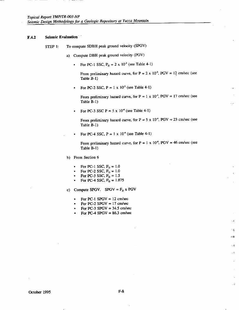
Topical Report YMPITR-003-NP Seismic Design Methodology for a Geologic Repository at Yucca Mountain
F.4.2 Seismic Evaluation
STEP 1: To compute SDBH peak ground velocity (SPGV)
a) Compute DBH peak ground velocity (PGV)
0 For PC-I SSC, PH = 2 x 10' (see Table 4-1)
From preliminary hazard curve, for P = 2 x' 10', PGV = 12 cm/sec (see Table B-1)
0 For PC-2 SSC, P = 1 x 10.3 (see Table 4-1)
From preliminary hazard curve, for P = 1 x 10 ', PGV = 17 cm/sec (see
Table B-i)
0 For PC-3 SSC P = 5 x 1 0 - (see Table 4-1)
From preliminary hazard curve, for P = 5 x 10-', PGV = 23 cm/sec (see
Table B-i)
0 For PC-4 SSC, P = 1 x 10- (see Table 4-1)
From preliminary hazard curve, for P = 1 x 10W, PGV = 46 cm/sec (see Table B-i)
b) From Section 6
"* For PC-I SSC, F, = 1.0 "* For PC-2 SSC, F, = 1.0 "* For PC-3 SSC, FD = 1.5 "* For PC-4 SSC, FD = 1.875
c) Compute SPGV. SPGV = F1 x PGV
"• For PC-I SPGV = 12 cm/sec "* For PC-2 SPGV = 17 cm/sec "* For PC-3 SPGV = 34.5 cm/sec "* For PC-4 SPGV = 86.3 cm/sec
October 1995 F-8
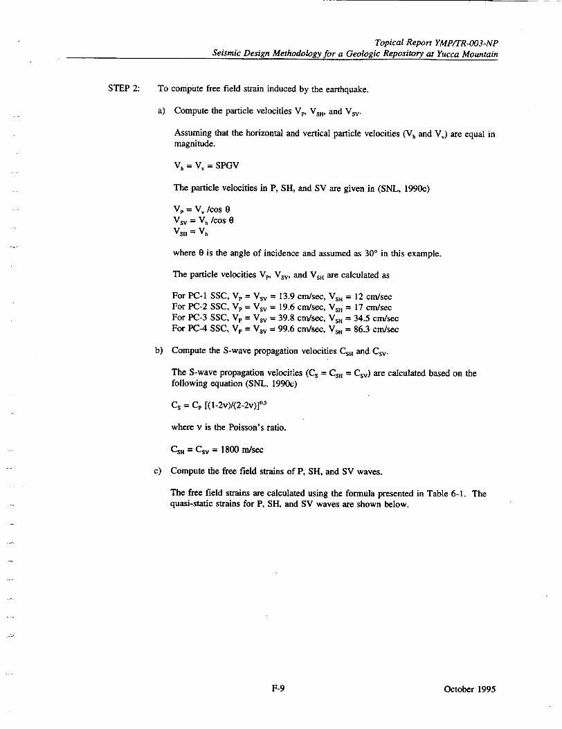
Topical Report YMP/TR-003-NP Seismic Design Methodology for a Geologic Repository at Yucca Mountain
STEP 2: To compiute free field strain induced by the earthquake.
a) Compute the particle velocities Vp, Vs,, and Vsv.
Assuming that the horizontal and vertical particle velocities (Vh and Vv) are equal in magnitude.
Vh = V, = SPGV
The particle velocities in P, SH, and SV are given in (SNL, 1990c)
Vp = V, /cos 0 Vsv = V /Cos 0 VSH Vh
where 0 is the angle of incidence and assumed as 300 in this example.
The particle velocities V,, Vsv, and VsH are calculated as
For PC-i SSC, Vp = Vsv = 13.9 cm/sec, VsH = 12 cm/sec For PC-2 SSC, Vp = Vsv = 19.6 cmn/sec, VsH = 17 cm/sec For PC-3 SSC, Vp = Vsv = 39.8 cm/sec, VsH = 34.5 cm/sec For PC-4 SSC, Vp = Vsv = 99.6 cm/sec, Vs5 = 86.3 cm/sec
b) Compute the S-wave propagation velocities Cs, and Csv.
The S-wave propagation velocities (Cs = CsH = Csv) are calculated based on the following equation (SNL, 1990c)
Cs = C. [(1-2v)/(2-2v)]°5
where v is the Poisson's ratio.
CSH = Csv = 1800 m/sec
c) Compute the free field strains of P, SH, and SV waves.
The free field strains are calculated using the formula presented in Table 6-1. The quasi-static strains for P, SH, and SV waves are shown below.
October 1995F-9
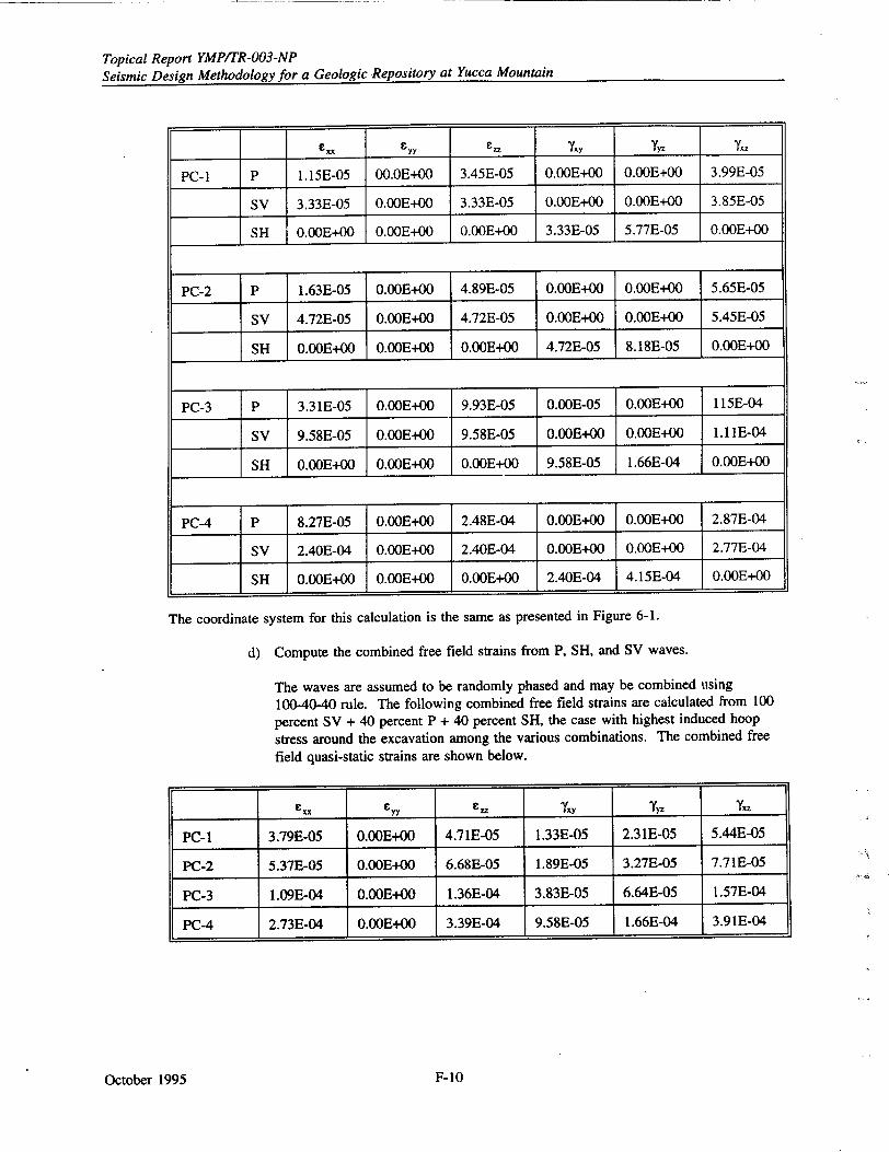
Topical Report YMPITR-003-NP Seismic Design Methodology for a Geologic Repository at Yucca Mountain
CyY Czz Y.Y yY.
PC- I P 1.15E-05 00.0E+00 3.45E-05 O.OOE+00 0.00E+00 3.99E-05
SV 3.33E-05 0.OOE+00 3.33E-05 0.00E+00 0.00E+00 3.85E-05
SH 0.00E+00 0.OOE+00 0.OOE+00 3.33E-05 5.77E-05 0.OOE+00
PC-2 P 1.63E-05 0.OOE+00 4.89E-05 0.OOE+00 0.OOE+00 5.65E-05
SV 4.72E-05 0.OOE+00 4.72E-05 0.OOE+00 0.OOE+00 5.45E-05
SH 0.00E+00 0.OOE+00 0.OOE+00 4.72E-05 8.18E-05 0.OOE+00
PC-3 P 3.3 1E-05 0.OOE+00 9.93E-05 0.OOE-05 0.OOE+00 115E-04
SV 9.58E-05 0.OOE+00 9.58E-05 0.OOE+00 0.00E+00 1.11E-04
SH 0.00E+00 O.OOE+00 0.OOE+00 9.58E-05 1.66E-04 0.00E+00
PC-4 P 8.27E-05 0.OOE+00 2.48E-04 0.OOE+00 0.OOE+00 2.87E-04
SV 2.40E-04 0.OOE+00 2.40E-04 0.OOE+00 0.OOE+00 2.77E-04
SH 0.OOE+00 0.00E+00 0.OOE+00 2.40E-04 4.15E-04 0.OOE+00
The coordinate system for this calculation is the same as presented in Figure 6-1.
d) Compute the combined free field strains from P, SH, and SV waves.
The waves are assumed to be randomly phased and may be combined using 100-40-40 rule. The following combined free field strains are calculated from 100
percent SV + 40 percent P + 40 percent SH, the case with highest induced hoop
stress around the excavation among the various combinations. The combined free field quasi-static strains are shown below.
e-rCx - C., _y, Yyz TX
PC-i 3.79E-05 0.00E+00 4.71E-05 1.33E-05 2.31E-05 5.44E-05
PC-2 5.37E-05 0.00E+00 6.68E-05 1.89E-05 3.27E-05 7.71E-05
PC-3 1.09E-04 0.OOE+00 1.36E-04 3.83E-05 6.64E-05 1.57E-04
PC-4 2.73E-04 0.OOE+00 3.39E-04 9.58E-05 1.66E-04 3.91E-04
October 1995 F-10
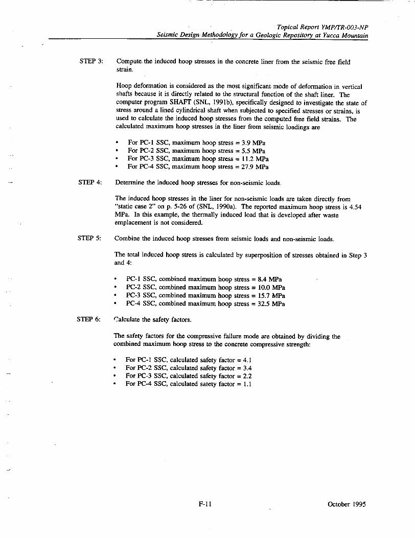
Topical Report YMPITR-003-NP Seismic Design Methodology for a Geologic Repository at Yucca Mountain
STEP 3: Compute-the induced hoop stresses in the concrete liner from the seismic free field strain.
Hoop deformation is considered as the most significant mode of deformation in vertical shafts because it is directly related to the structural function of the shaft liner. The computer program SHAFT (SNL, 1991b), specifically designed to investigate the state of stress around a lined cylindrical shaft when subjected to specified stresses or strains, is used to calculate the induced hoop stresses from the computed free field strains. The calculated maximum hoop stresses in the liner from seismic loadings are
* For PC-i SSC, maximum hoop stress = 3.9 MPa * For PC-2 SSC, maximum hoop stress = 5.5 MPa * For PC-3 SSC, maximum hoop stress = 11.2 MPa • For PC-4 SSC, maximum hoop stress = 27.9 MPa
STEP 4: Determine the induced hoop stresses for non-seismic loads.
The induced hoop stresses in the liner for non-seismic loads are taken directly from "static case 2" on p. 5-26 of (SNL, 1990a). The reported maximum hoop stress is 4.54 MPa. In this example, the thermally induced load that is developed after waste emplacement is not considered.
STEP 5: Combine the induced hoop stresses from seismic loads and non-seismic loads.
The total induced hoop stress is calculated by superposition of stresses obtained in Step 3 and 4:
* PC-1 SSC, combined maximum hoop stress = 8.4 MPa * PC-2 SSC, combined maximum hoop stress = 10.0 VPa • PC-3 SSC, combined maximum hoop stress = 15.7 MWa * PC-4 SSC, combined maximum hoop stress = 32.5 MPa
STEP 6: Calculate the safety factors.
The safety factors for the compressive failure mode are obtained by dividing the combined maximum hoop stress to the concrete compressive strength:
* For PC-I SSC, calculated safety factor = 4.1 * For PC-2 SSC, calculated safety factor = 3.4 • For PC-3 SSC, calculated safety factor = 2.2 * For PC-4 SSC, calculated satety factor = 1.1
October 1995F-11I
Topical Report YMPITR-003-NP Seismic Design Methodology for a Geologic Repository at Yucca Mountain
STEP 7: Compare the calculated safety factors with the recommended safety factors.
The recommended safety factors listed in Table 6-2 are compared with the calculated
safety factors to determine the adequacy of the design.
* For PC-1 SSC, calculated safety factor (4.1) > recommended safety factor (1.0),
O.K.
"• For PC-2 SSC, calculated safety factor (3.4) > recommended safety factor (1.4),
O.K.
"* For PC-3 SSC, calculated safety factor (2.2) > recommended safety factor (1.8),
O.K.
* For PC-4 SSC, calculated safety factor (1.1) < recommended safety factor (1.8), the
liner is not conservative for PC-4 design and higher strength concrete should be
specified.
F.4.3 Other Considerations
Axial or horizontal tension cracks may arise from alternating compression and tension caused by
seismic waves which are not considered in this sample problem. A fully bonded but partially cracked
liner will likely retain most of its thrust capacity and consequently its support function (SNL, 1990a).
However, for postclosure sealing performance, wire mesh and rebar reinforcement may be necessary
for prevention of the tensile cracks.
For maintaining the simplicity of the example application, thermal load, discussed in Section 6.4, is
not considered here. The impact of thermal load to the design can be significant (SNL, 1991a) and
must be put into consideration.
Other major components for the ground support systems include the rockbolts and the shotcrete.
Design of rockbolt and shotcrete under seismic impact are both described in drift design methodology
(SNL, 1991a).
October 1995 F-12

Topical Report YMP/TR-003-NP Seismic Design Methodology for a Geologic Repository at Yucca Mountain
APPENDIX G
REFERENCES
October 1995G-1
Topical Report YMP/TR-003-NP Seismic Design Methodology for a Geologic Repository at Yucca Mountain
APPENDIX G
REFERENCES
51 Federal Register 30028, 1986, August 21. U.S. Nuclear Regulatory Commission. Policy Statement on Safety
Goals for the Operations of Nuclear Power Plants.
55 Federal Register 28771, 1990, July 13. U. S. Nuclear Regulatory Commission. Notice of Receipt of
Department of Energy Petition for Rulemaking to 10 CFR Part 60.
59 Federal Register 52255, 1994, October 17. U.S. Nuclear Regulatory Commission. Proposed Rule Changes to
10 CFR Parts 50, 52.
59 Federal Register 63389, 1994, December 8. U.S. Nuclear Regulatory Commission. Proposed Policy
Statement on the Use of Probabilistic Risk Assessment Methods in Nuclear Regulatory Activities.
60 Federal Register 10880, 1995. Identification and Characterization of Seismic Sources and Determination of
Safe Shutdown Earthquake Ground Motions. NRC Regulatory Guide DG-1032.
60 Federal Register 15180, 1995, March 22. U.S. Nuclear Regulatory Commission. Proposed Rule Change to
10 CFR Part 60.
ACI (American Concrete Institute), 1985. Code Requirements for Nuclear Safety-Related Concrete Structures
and Commentary. ACI 349-85 and ACI 349R-85. Detroit, Michigan.
AISC (American Institute of Steel Construction), 1988. Manual of Steel Construction, Load and Resistance
Factor Design (LRFD). First Edition. Chicago, Illinois.
ASCE (American Society of Civil Engineers), 1984. Guidelines for the Seismic Design of Oil and Gas Pipeline
Systems. New York, New York.
ASCE, 1986. Seismic Analysis of Safety-Related Nuclear Structures and Commentary on Standard for Seismic
Analysis of Safety-Related Nuclear Structures. Standard 4. New York, New York.
ASCE, 1993, draft. Seismic and Dynamic Analysis and Design Considerations for High Level Nuclear Waste
Repositories. New York, New York.
ASLB (Atomic Safety and Licensing Board), 1982. Initial Decision Removing Show Cause Order and
Approving Restart: General Electric Test Reactor. Majority Opinion by Dr. George Ferguson and Dr. Harry
Foreman, USNRC, Docket No. 50-70 SC, Washington, D C.
ASME (American Society of Mechanical Engineers), 1991. Boiler and Pressure Vessel Code, Section mI, Rules
for Construction of Nuclear Power Plant Components, New York, New York.
ATC (Applied Technology Council), 1978, June. Tentative Provisions for the Development of Seismic
Regulation for Buildings. ATC 3-06. National Bureau of Standards Publication 510, Washington, D.C.:
National Bureau of Standards
Barton, N., 1984. Rock Mass Quality and Support Recommendations for Basalt at the Candidate Repository
Horizon, Based on the Q-System. SD-BWI-ER-012, Rev. 1. Salt Lake City, Utah: Terra Tek Engineering for
Rockwell Hanford Operations.
Barton, N., S. Bandis, and K. Bakhtar, 1985. "Strength, Deformation, and Conductivity Coupling of Rock
Joints." International Journal of Rock Mechanics, Mining Sciences, and Geomechanics Abstracts, 22(3):121-140.
Barton, N., R. Lien, and J. Lunde, 1974. "Engineering Classification of Rock Masses for the Design of Tunnel
Support." Rock Mechanics, 6:189-236. Wien, New York: Springer Verlag.
October 1995 G-2
Topical Report YMP/TR-003-NP Seismic Design Methodology for a Geologic Repository at Yucca Mountain
Barton, N., F. Loset, R. Lien, and J. Lunde, 1980. "Application of Q System in Design Decisions Concerning Dimensions and Appropriate Support for Underground Installations." Proceedings of the International Conference on Subsurface Space, Rockstore, 2:553-562. Great Britain: Pergamon Press, Ltd.
Berrill, J. B., 1983. "Two-Dimensional Analysis of the Effects of Fault Rupture on Buildings with Shallow Foundations." Soil Dynamics and Earthquake Engineering. Vol. 2, No. 3.
Bieniawski, Z. T., 1976. "Rock Mass Classification in Rock Engineering." Proceedings of the Symposium on Exploration for Rock Engineering, Johannesburg, South Africa; pp. 97-106. Capp Town, Rotterdam, Brookfield, Vermont: A. A. Balkema.
Bieniawski, Z. T., 1979. "The Geomechanics Classification in Rock Engineering Applications." Proceedings of the 4th International Congress on Rock Mechanics, Montreaux, Switzerland, 2:41-48. Lisbon, Portugal: International Society of Rock Mechanics.
Bieniawski, Z. T., 1973. "Engineering Classification of Jointed Rock Masses." Transactions, South African Institution of Civil Engineers, 15(12):335-344.
Brady, B. H. G. and E. T. Brown, 1985. Rock Mechanics for Underground Mining. London, England: George Allen & Unwin.
Brown, E. T. and J. A. Hudson, 1974. "Fatigue Failure Characteristics of Some Models of Jointed Rock." Earthquake Engineering and Structural Dynamics, 2, 379-386.
Brown, I. R., T. L. Brekke, and G. E. Korbin, 1981. "Behavior of the Bay Area Rapid Transit Tunnels Through the Hayward Fault," Report No. UMTA-CA-06-0120-81-1. Washington D.C.: U.S. Department of Transportation, Urban Mass Transportation Administration.
Center for Nuclear Waste Regulatory Analyses, 1992. Hsiung, S. M., A. H. Chowdhury, W. Blake, M. P. Ahola, and A. Ghosh. Field Site Investigation: Effect on Mine Seismicity on a Jointed Rock Mass. CNWRA 92-012. San Antonio, Texas.
Center for Nuclear Waste Regulatory Analyses, 1993. Hsiung, S. M., D. D. Kana, M. P. Ahola, A. H. Chowdhury, and A. Ghosh, 1993. Laboratory Characterization of Rock Joints. CNWRA 93-013. San Antonio, Texas.
Chen, E. P., 1990. "A Coastitutive Model for Jointed Rock Mass With Two Intersecting Sets of Joints," Proceedings of the International Conference on Jointed and Faulted Rock, Vienna, Austria. Rotterdam, Brookfield, Vermont: A. A. Balkema.
CRWMS M&O (Civilian Radioactive Waste Management System Management and Operating Contractor), 1994a. Initial Summary Report for Repository/Waste Package Advanced Conceptual Design. B00000000-01717-5705-00015 Rev. 00. Las Vegas, Nevada: U.S. Department of Energy, Yucca Mountain Site Characterization Project.
CRWMS M&O, 1994b. Seismic Design Inputs for the Exploratory Studies Facility of Yucca Mountain. BABOOOOOO-01717-5705-00001, Rev. 02, 1994. Las Vegas, Nevada: U.S. Department of Energy, Yucca Mountain Site Characterization Project.
Cummings, R. A., F. S. Kendorski, and Z. T. Bieniawski, 1982. Caving Mine Rock Mass Classification and Support Estimation. Engineering International, Inc., Contract No. J0100103. Washington, D.C: U.S. Bureau of Mines, Department of the Interior.
Cundall, P. A., 1980. UDEC - A Generalized Distinct Element Program for Modelling Jointed Rock, Final Technical Report to European Research Office. U.S. Army Contract DAJA37-79-C-0548, Report No. PCAR-18(0). London, England: U.S. Army, European Research Office.
October 1995G-3
Topical Report YMPITR-003-NP Seismic Design Methodology for a Geologic Repository at Yucca Mountain
Cundall, P. A. and J. V. Lemos, 1990. "Numerical Simulation of Fault Instabilities with the
Continuously-Yielding Joint Model." Proceedings of the 2nd International Symposium on Rockbursts and
Seismicity in Mines. Rotterdam, Brookfield, Vermont: A. A. Balkema.
Cundall, P. A., 1971. "A Computer Model for Simulating Progressive, Large-Scale Movement in Blocky Rock
Systems." Symposium of the International Society of Rock Mechanics, Nancy, France.
Deere, D. U., A. J. Hendron Jr., F. D. Patton, and E. J. Cording, 1966. "Design of Surface and Near Surface
Construction in Rock," Proceedings of the 8th U.S. Symposium on Rock Mechanics, Failure and Breakage of
Rock, Minneapolis, Minnesota, pp. 237-302. Baltimore, Maryland: Port City Press, Inc.
Desai, D. B., J. L. Merritt, and B. Chang, 1989. Shake and Slip to Survive - Tunnel Design."
Proceedings of the Rapid Excavation and Tunneling Conference, pp. 13-30. Littleton, Colorado: Society for
Mining, Metallurgy, and Exploration, Inc.
DOE (U.S. Department of Energy), 1988. Site Characterization Plan, Yucca Mountain Site, Nevada Research
and Development Area, Nevada. DOEIRW-0199. Washington, D.C.: Office of Civilian Radioactive Waste
Management.
DOE, 1994a. Topical Report: Methodology to Assess Fault Displacement and Vibratory Ground Motion
Hazards at Yucca Mountain. YMP/TR-002-NP. Las Vegas, Nevada: Office of Civil,.n Radioactive Waste
Management.
DOE, 1994b. Natural Phenomena Hazards Design and Evaluation Criteria for Department of Energy Facilities.
DOE-STD-1020-94. Washington, D.C.: Office of Safety Appraisals.
DOE, 1994d. Engineered Barrier System Design Requirements Document. YMP/CM-0024, Rev. 0, ICN 1.
Washington, D.C.: Office of Civilian Radioactive Waste Management.
DOE, 1995. Probabilistic Analyses of Vibratory Ground Motion and Fault Displacement of Yucca Mountain.
Study Plan for 8.3.1.17.3.6. Las Vegas, Nevada: Office of Civilian Radioactive Waste Management.
DOE, 1994c. Repository Design Requirements Document. YMP/CM-0023, Rev. 0, ICN 1. Washington, D.C.:
Office of Civilian Radioactive Waste Management.
Dowding, C. H. and A. Rozen, 1978. "Damage to Rock Tunnels from Earthquake Shaking." Journal of
Geotechnical Engineering Division, American Society of Civil Engineers, 104(GT2): 175-191.
Duncan, J. M., and G. Lefebvre, 1973. "Earth Pressures on Structures Due to Fault Movement." Proceedings of
the American Society of Civil Engineers, Vol. 99, No. SM12. New York, New York.
EDA (Engineering Decision Analysis, Inc.), 1980a. Additional Investigations to Determine the Effects of
Combined Vibratory Motions and Surface Rupture Offset Due to an Earthquake on the Postulated Verona Fault.
Report Submitted to the U.S. Nuclear Regulatory Commission. Docket No. 50-70 SC. Palo Alto, California.
EDA, 1980b. Summary Report Structural Seismic Investigations of General Electric Test Reactor. Report
Submitted to U.S. Nuclear Regulatory Commission. Docket No. 50-70 SC. Palo Alto, California.
Einstein, H. H., W. Steiner, and G. B. Baecher, 1979. "Assessment of Empirical Design Methods for Tunnels in
Rocks." Proceedings of the 1979 Rapid Excavation and Tunneling Conference, 1:683-706. Baltimore,
Maryland: Port City Press, Inc.
EPRI (Electric Power Research Institute), 1989. Seismic Hazard Methodology for the Central and Eastern
United States, Vol. 1-10. NP-4726. Palo Alto, California.
EPRI, 1991. A Methodology for Assessment of Nuclear Power Plant Seismic Margin. EPRI NP-6041-SL, Rev.
1. Palo Alto, California.
October 1995 G-4
Topical Report YMP/TR-003-NP Seismic Design Methodology for a Geologic Repository at Yucca Mountain
Federal Highway Administration, 1981. Owen, G. N., and R. E. Scholl. Earthquake Engineering of Large Underground Structures. FHWA/RD-80/195. Washington, D.C.
Fisher, J. W., P. V. Galambos, G. L. Kulak, and M. K. Ravindra, 1978, September. "Load and Resistance Factor Design Criteria for Connections." Journal of Structural Division, American Society of Civil Engineers, Vol. 104, ST9, pp. 1427-1441.
Frame, P. A., 1995. "Evaluation of Fault Offset for the Coyote Dam Outlet Work," AEG News, Vol. 38, No. 2, pp. 26-28. Association of Engineering Geologists.
Gerrard, C. M., 1982. "Elastic Models of Rock Masses Having One, Two and Three Sets of Joints." International Journal of Rock Mechanics, Mining Sciences and Geomechanics Abstracts, 19:15-23.
Glasstone, S., 1962. The Effects of Nuclear Weapons. U.S. Department of Defense and U.S. Atomic Energy Commission.
Hardy, M. P. and S. J. Bauer, 1993. "Design of Underground Repository Openings in Hard Rock to Accommodate Vibratory Ground Motions." Proceedings of the Dynamic Analysis and Design Considerations for High Level Nuclear Waste Repositories. New York, New York: American Society of Civil Engineers.
Hendron, A. and G. Fernandez, 1983. "Dynamic and Static Design Considerations for Underground Chambers." Proceedings of the Symposium on Seismic Design of Embankments and Caverns, pp. 157-197. Philadelphia, Pennsylvania: American Society of Civil Engineers.
Hoek, E., 1981. "Geotechnical Design of Large Openings at Depth." Proceedings of the Rapid Excavation and Tunnel Conference, 2:1032-1044. New York, New York: American Institute of Metallurgical, Mining, and Petroleum Engineers.
Hoek, E. and E. T. Brown, 1980. Underground Excavations in Rock, p. 132. London, England: Institution of Mining and Metallurgy.
Hoek, E., D. Wood, and S. Shah, 1992, September. "A Modified Hoek-Brown Failure Criterion for Jointed Rock Masses." Proceedings of the International Society for Rock Mechanics Symposium: Eurock '92, Chester, United Kingdonm London, England: International Society for Rock Mechanics.
IEEE (Institute of Electrical and Electronic Engineers), 1987. IEEE Recommended Practice for Seismic Qualification of Class 1E Equipment for Nuclear Power Generating Stations. ANSI/IEEE 344. New York, New York.
Itasca, 1993. UDEC: Universal Distinct Element Code, Version 1.8, Volume I: User's Manual. Minneapolis, Minnesota: Itasca Consulting Group, Inc.
Jaeger, J.C, and N.G.W. Cook, 1979. Fundamentals of Rock Mechanics, Third Edition. London, Great Britain: Fletcher, & Sons, Ltd.
Kendorski, F. S., R. A. Cummings, Z. T. Bieniawski, and E. H. Skinner, 1983. "Rock Mass Classification for Block Caving Mine Drift Support." Proceedings of the 5th International Congress on Rock Mechanics, pp. B5 163. Melbourne, Australia: International Society of Rock Mechanics.
Kennedy, R. P., 1993. "Performance Goal-Based Seismic Design Criteria for High-Level Waste Repository Facilities." Proceedings of the Symposium on Dynamic Analysis and Design Considerations for High-Level Nuclear Waste Repositories, pp. 28-52. New York, New York: American Society of Civil Engineers.
Kennedy, R. P. and R. H. Kincaid, 1985. "Fault Crossing Design for Buried Gas and Oil Pipelines." Proceedings of the Seismic Performance of Pipelines and Storage Tanks, Pressure Vessels and Piping Conference, PVP Vol. 98-4. New York, New York: American Society of Mechanical Engineers.
Kennedy, R. P., A. W. Chow, and R. A. Williamson, 1977. "Fault Movement Effects on Buried Oil Pipelines." Transportation Engineering Journal of the American Society of Civil Engineers, Vol. 103, No. TE5.
October 1995G-5
Topical Report YMP/TR-003-NP Seismic Design Methodology for a Geologic Repository at Yucca Mountain
Kennedy, R. P., S. A. Short, J. R. McDonald, M. W. McCann Jr., R. C. Murrary, J. R. Hill, V. Gopinath, 1990.
Design and Evaluation Guidelines for Department of Energy Facilities Subjected to Natural Phenomena
Hazards. UCRL-15910, Office of Safety Appraisals, U.S. Department of Energy.
Kumar, A., 1968. "The Effect of Stress Rate and Temperature on the Strength of Basalt and Granite,"
Geophysics, June, Vol. 31, No. 3, pp. 501-510.
Kupfer, D. H., S. Muessig, G. I. Smith, and G. N. White, 1955. "Arvin-Tehachapi Earthquake Damage Along
the Southern Pacific Railroad Near Bealville, California", in "Earthquakes in Kern County, California During
1952," California Division of Mines Bulletin 171, pp. 67-74.
Laubscher, D. H., 1984, April. "Design Aspects and Effectiveness of Support Systems in Different Mining
Conditions," Journal of Mining and Metallurgy, Vol. 93 (Section A), pp. 70-81.
Lauffer, H., 1988. "Zur Bebirgsklassfizierung bei Fr~svortrieben," Felsbau, Vol. 6, No. 3, pp. 137-149.
Lee, J. S., D. Veneziano, and H. H. Einstein, 1990. "Hierarchial Fracture Trace Model", Rock Mechanics
Contributions and Challenges, Proceedings of the 31st U. S. Symposium, pp. 261-268. Rotterdam, Brookfield, Vermont: A. A. Balkema.
Lemos, J. V., 1987. A Distinct Element Model for Dynamic Analysis of Jointed Rock Application to Dam
Foundation and Fault Motion. Master's thesis, University of Minnesota, Minneapolis.
Lindholm, U.S., L.M. Yealdey, and A. Nagy, 1974. "The Dynamic Strength and Fracture Properties of Dresser
Basalt," International Journal for Rock Mechanics, Mining Sciences, and Geomechanics Abstracts, Vol. 11, pp.
181-191, Great Britain: Pergamon Press.
LLNL (Lawrence Livermore National Laboratory) and BNL (Brookhaven National Laboratory), 1994. Kennedy,
R. P. and S. A. Short. Basis for Seismic Provisions of DOE Standard 1020-94. UCRL-CR- 111478 and
BNL-52418. Livermore, California
Long, J. C. S., D. Billaux, K. Hestir, and J. P. Chiles, 1987. "Some Geostatistical Tools for Incorporating
Spatial Structure in Fracture Network Modelling." Proceedings of the 6th International Congress on Rock
Mechanics, Vol. 1. Rotterdam, Boston: A. A. Balkema.
"Looking at Reviving Line," 1994, October 24. Engineering News Record, p. 20. McGraw-Hill.
Louderback, G. D., 1950, November. "Faults and Engineering Geology." Engineering Geology (Berkley)
Volume, pp. 125-150, Boulder, Colorado: Geological Society of America.
Menges, C.M., F. H. Swan, J. A. Oswald, J. R. Wesling, J. A. Coe, J. W. Whitney, and A. P. Thomas, 1995.
"Preliminary Results of Paleoseismic Investigations of Quaternary Faults on Eastern Yucca Mountain, Nye
County, Nevada." Proceedings 5th International High-Level Radioactive Waste Management Conference, pp.
2373-2390, Las Vegas, Nevada. New York, New York: American Society of Civil Engineers.
Morland, L. W., 1974. "Elastic Response of Regularly Jointed Media." The Geophysical Journal of the Royal Astronomical Society, 37:435-446.
NCRP (National Council on Radiation Protection and Measurements), 1971, Basic Radiation Protection Criteria,
NCRP Report Number 39, Bethesda, Maryland
Nelson, T. A., Q. A. Hossain, and R. C. Murray, 1993, August. "Guidelines for the Development of Natural
Phenomena Hazards Design Criteria for Surface Facilities." Proceedings of the Symposium on Dynamic Analysis
and Design Considerations for High-Level Nuclear Waste Repositories. American Society of Civil Engineers.
Niccum, M. R., L. S. Cluff, F. Chamorro, and L. Wyllie, 1976. "Banco Central de Nicaragua: A Case History
of a High-Rise Building that Survived Surface Fault Rupture." Proceedings of the Engineering Geology and Soils
Engineering Symposium No. 14. Boise, Idaho: State of Idaho, Division of Highways.
October 1995 G-6
Topical Report YMP/TR-003-NP Seismic Design Methodology for a Geologic Repository at Yucca Mountain
NRC (U.S. Nuclear Regulatory Commission), 1973. Damping Values for Seismic Design of Nuclear Power Plants, Regulatory Guide 1.61, Washington, D.C.
NRC, 1978a. Newmark, N. M. and W. J. Hall. Development of Criteria for Seismic Review of Selected Nuclear Power Plants. NUREG/CR-0098. Washington, D.C.
NRC, 1978b, March. Design Criteria for the Structural Analysis of Shipping Cask Containment Vessels. Regulatory Guide 7.6, Revision 1. Washington, D.C.
NRC, 1978c, September. Seismic Design Classification. Regulatory Guide 1.29, Revision 3. Washington, D.C.
NRC, 1983. PRA Procedures Guide. NUREG/CR-23001. Chapter 10, Vol. 2. Prepared by American Nuclear Society and Institute for Electrical and Electronic Engineers. Washington, D.C.
NRC, 1989a. Load Combinations for the Structural Analysis of Shipping Casks for Radioactive Material. Regulatory Guide 7.8, Revision 1. Washington D.C.
NRC, 1991a. Banyopadhyay, K. K., and C. H. Hoffmayer. Seismic Fragility of Nuclear Power Plant Components. Vols. 1-4. NUREG/CR-4659. Washington, D.C.
NRC, 199 1b. Kana, D. D., B. H. G. Brady, B. W. Vanzant, and P. K. Nair. Critical Assessment of Seismic and Geomechanics Literature Related to A High-Level Nuclear Waste Underground Repository. NUREG/CR-5440. Washington, D.C.
NRC, 1992. McConnell, K. I., M. E. Blackford, and A-K Ibrahim. Staff Technical Position on Investigations to Identify Fault Displacement Hazards and Seismic Hazards at a Geologic Repository. NUREG-1451. Washington, D.C.
NRC, 1994. McConnell, K. I. and M. P. Lee. Staff Technical Position on Consideration of Fault Displacement Hazards in Geologic Repository Design. NUREG-1494. Washington, D.C.
Office of Nuclear Waste Isolation, 1982. Barton, N. Modeling Rock Joint Behavior from In Situ Block Tests: Implications for Nuclear Waste Repository Design. ONWI-308. Columbus, Ohio.
Olsson, W. A., 1985. "Normal Stress History Effects on Friction in Tuff." EOS, Transactions of the Geophysical Union, 66:1101.
Olsson, W. A., 1987. "The Effects of Changes in Normal Stress on Rock Friction." Constitutive Laws for Engineering Materials-Theory and Applications, pp. 1059-1066. New York, New York: Elsevier Scientific Publishing Company.
Pacific Gas & Electric Co., 1988, September. Seismic Fragilities of Civil Structures and Equipment Components at the Diablo Canyon Power Plant. QA Report Number 34001.01-R014. San Francisco, California.
Pande, G. N., G. Beer, and J. R. Williams, 1990. Numerical Methods in Rock Mechanics. John Wiley & Sons, Limited, West Sussex, England.
Papaliangas T., S. R. Hencher, A. C. Lumsden, and S. Monolopoulou, 1993. "The Effect of Frictional Fill Thickness on the Shear Strength of Rock Discontinuities." International Journal of Rock Mechanics and Mining Sciences, Vol. 30, No. 2., pp. 81-91.
Plona, T.J., and J.M. Cook, 1995. "Effects of Stress Cycles on Static and Dynamic Young's Moduli in Castlegate Sandstone," Proceedings of the 35th U.S. Symposium on Rock Mechanics, University of Nevada at Reno, 5-7 June 1995, Daemen and Schultz (eds.), pp. 155-160, Rotterdam, Brookfield, Vermont: A.A. Balkema.
Reed, J. W., R. L. Sharpe, and S. A. Webster, 1979. "An Analysis of a Nuclear Test Reactor for Surface Rupture Offset." Boston, Massachusetts: American Society of Civil Engineers Spring Conference.
October 1995G-7
Topical Report YMPITR-003-NP Seismic Design Methodology for a Geologic Repository at Yucca Mountain
Russell, F. M., D. R. M. Armstrong, and R. Talbot, 1983. "Analysis of Stoping Sequence and Support
Requirements in a High Stress Environment - ZCCM - Mufulira Division." Rockbursts: Prediction and Control,
pp. 161-173. London, England: The Institution of Mining and Metallurgy.
Schmidt, B., 1987, March. "Learning From Nuclear Waste Repository Design: The Ground-Control Plan."
Proceedings of the VI Australian Tunnelling Conference, 1:11-19. Victoria, Australia: The Australasion Institute
of Mining and Metallurgy.
Selna, L. G., and M. D. Cho, 1973. "Banco de America, Managua, A High-Rise Shear Wall Building
Withstands a Strong Earthquake." Proceedings of the Earthquake Engineering Research Institute Conference.
San Francisco, California.
Senseny, P. E., 1993. "Stress Wave Loading of a Tunnel: A Benchmark Study," Dynamic Analysis and Design
Considerations for High Level Nuclear Waste Repositories, pp. 311-338. Edited by Q. Hossain. New York,
New York: American Society of Civil Engineers.
Serafim, J. L., and J. P. Pereira, 1983. "Consideration of the Geomechanics Classification of Bieniawski."
Proceedings of the International Symposium on Er gineering Geology and Underground Construction, Lisbon,
Portugal. Lisbon, Portugal: International Association of Engineering Geology.
Sharma, S., and W. R. Judd, 1991. "Underground Opening Damage from Earthquake, " Engineering Geology,
30:263-276.
Shi, G., 1990, June. "Forward and Backward Discontinuous Deformation Analyses of Rock Block Systems."
Proceedings of the International Symposium on Rock Joint, Loen, Norway, pp. 731-743. Rotterdam, Brookfield,
Vermont: A. A. Balkema.
Short, S.A., R.C. Murray, T.A. Nelson, and J.R. Hill, 1990, December. "Deterministic Seismic Design and
Evaluation Criteria to Meet Probabilistic Performance Goals." Proceedings of the Third Symposium on Current
Issues Related to Nuclear Power Plant Structures, Equipment and Piping. Orlando, Florida. Raleigh, North
Carolina: North Carolina State University.
Singh, B., 1973. "Continuum Characterization of Jointed Rock Masses, Part I-The Constitutive Equations."
International Journal of Rock Mechanics and Mining Sciences, 10:311-335.
SNL (Sandia National Laooratories), 1982. Thomas, R. K. A Continuum Description for Jointed Media.
SAND81-2615. Albuquerque, New Mexico.
SNL, 1984. Biffle, J. H. JAC-A Two-Dimensional Finite Element Computer Program for the Non-Linear
Quasistatic Response of Solids with the Conjugate Gradient Method. SAND81-0998. Albuquerque, New
Mexico.
SNL, 1986a. URS/John A. Blume & Associates, Engineers. Ground Motion Evaluations at Yucca Mountain,
Nevada, With Applications to Repository Conceptual Design and Siting. SAND85-7104. Albuquerque, New
Mexico.
SNL, 1986b. Zimmerman, R. M. and R. E. Finely. Summary of Geomechanical Measurements Taken In and
Around the G-Tunnel Underground Facility. SAND86-1015. Albuquerque, New Mexico.
SNL, 1987a. Chen, E. P. A Computation Model for Jointed Media with Orthogonal Sets of Joints.
SAND86-1122. Albuquerque, New Mexico.
SNL, 1990a. Richardson, A. M. Preliminary Shaft Liner Design Criteria and Methodology Guide.
SAND88-7060. Albuquerque, New Mexico.
SNL, 1990b. Blanford, M. L. and S. W. Key. The Joint Empirical Model-An Equivalent Continuum Model for
Jointed Rock Model. SAND87-7072. Albuquerque, New Mexico.
October 1995 G-8
Topical Report YMP/TR-003-NP Seismic Design Methodology for a Geologic Repository at Yucca Mountain
SNL, 1990c. Subrumanian, et al., Working Group Report, Exploratory Shaft Seismic Design Bases, Yucca Mountain Project, SAND88-1203, Albuquerque, New Mexico.
SNL, 199 Ia. Hardy, M. P. and S. J. Bauer. Drift Design Methodology and Preliminary Application for the Yucca Mountain Project. SAND89-0837. Albuquerque, New Mexico.
SNL, 1991b, December. Documentation and Verification of the Shaft Code. SAND88-7065. Albuquerque, New Mexico.
Subramanian, C. V., N. Abrahamson, A. H. Hadjian, L. J. Jardine, J. B. Kemp, 0. K. Kiciman, C. W. Ma, J. King, W. Andrews, and R. P. Kennedy, 1989. "Preliminary Seismic Design Cost-Benefit Assessment of the Tuff Repository Waste-Handling Facilities." SAND 88-1600 UC-70. Albuquerque, New Mexico: Sandia National Laboratories.
Sun, Z., C. Gerrard, and 0. Stephansson, 1985. "Rock Joint Compliance Tests for Compression and Shear Loads." International Journal of Rock Mechanics and Mining Sciences, 22(4):197-213. Great Britain.
Terzaghi, K., 1946. "Rock Defects and Loads on Tunnel Supports." Rock Tunneling with Steel Supports, pp. 15-99. Youngstown, Ohio: Commercial Shearing and Stamping Company.
U.S. Department of Transportation, 1981. Brown, I. R., G. E. Korbin, and T. L. Brekke. Behavior of the Bay Area Rapid Transit Tunnels Through the Hayward Fault. UMTA-CA-06-0120-81-1.
Uniform Building Code (UBC), 1994. Whittier, California: International Conference of Building Officials.
USGS (U.S. Geological Survey), 1986. Lockner, D. A., and J. D. Byerlee. Laboratory Measurements of Velocity-Dependent Frictional Strength. Open-File Report 86-417. Menlo, California.
Wang, Jing-Ming, 1985, August. "The Distribution of Earthquake Damage to Underground Facilities During the Tang-Shan Earthquake." Earthquake Spectra, Vol. 1, No. 4.
Wells, D. L., and K. J. Coppersmith, 1994. "New Empirical Relationships among Magnitude, Rupture Length, Rupture Width, Rupture Area, and Surface Displacement." Bulletin, Vol. 84, No. 4, pp. 974-1002. Seismological Society of America. El Cerrito, California.
Wickham, G. E., H. R. Tiedeman, and E. H. Skinner, 1972. "Support Determinations Based on Geologic Predictions." Proceedings of the Rapid Excavation and Tunneling Conference, 1:43-64.
Williams, J. R., G. Hocking, and G. G. W. Mustoe, 1985. "The Theoretical Basis of the Discrete Element Method." Proceedings of NUMETA '85, Numerical Methods in Engineering, Theory and Applications. Rotterdam, Brookfield, Vermont: A. A. Balkema.
Wyllie, L. A., Jr., 1973. "Performance of Banco Central Building." Proceedings of the Earthquake Engineering Research Institute Conference. San Francisco, California.
Yale, D.P., J.A. Nieto, and S.P. Austin, 1995. "The Effect of Cementation on the Static and Dynamic Mechanical Properties of the Rotleigendes Sandstone," Proceedings of the 35th U.S. Symposium on Rock Mechanics, Univesity of Nevada at Reno, 5-7 June 1995, pp. 169-175, Daemen and Schultz (eds.) Rotterdam, Brookfield, Vermont: A.A. Balkema.
Yoshikawa, K. and G. Fukuchi, 1984. "Earthquake Damage to Railway Tunnels in Japan." Advances in Tunnelling Technology and Subsurface Use, Proceedings of the International Tunnelling Association, Vol. 4, No. 3, pp. 75 - 83. Pergammon Press.
Yudhbir, W. Lemanza, and F. Prinzl, 1983. "An Empirical Failure Criterion for Rock Masses." Proceedings of the 5th International Congress on Rock Mechanics, pp. B1-B8. Melbourne, Australia: International Society of Rock Mechanics.
October 1995G-9
Topical Report YMPITR-003-NP Seismic Design Methodology for a Geologic Repository at Yucca Mountain
PUBLIC LAWS AND REGULATIONS
Title 10 Code of Federal Regulations, Part 60, 1995. Disposal of High-Level Radioactive Wastes in Geologic Repositories. Washington, D.C.: U.S. Nuclear Regulatory Commission.
Title 10 Code of Federal Regulations, Part 20, 1995. Standards for Protection Against Radiation. Washington, D.C.: U.S. Nuclear Regulatory Commission.
Title 10 Code of Federal Regulations, Part 100, 1995. Reactor Site Criteria. Washington, D.C.: U.S. Nuclear Regulatory Commission.
Title 10 Code of Federal Regulations, Part 71, 1992. Licensing Requirements for the Independent Storage of
Spent Nuclear Fuel and High-Level Radioactive Waste. Washington, D.C.: U.S. Nuclear Regulatory Commission.
Nuclear Waste Policy Act of 1982, as amended by the Nuclear Waste Policy Amendments Act of 1987. Public Law 97-425, 42 U.S.C. § 10101. 1983.
Title 10 Code of Federal Regulations, Part 72, 1992. Packaging and Transportation of Radioactive Material. Washington, D.C.: U.S. Nuclear Regulatory Commission.
Title 10 Code of Federal Regulations, Part 50, 1986. Safety Goals for the Operations of Nuclear Power Plants; Policy Statement. 51 Federal Register 50028. Washington, D.C.: U.S. Nuclear Regulatory Commission.
October 1995 G-10