Embed Size (px)
Citation preview
Accepted Manuscript
Seismic characteristics of fluid escape pipes in sedimentary basins: implications forpipe genesis
Joe Cartwright, Carlos Santamarina
PII: S0264-8172(15)00117-8
DOI: 10.1016/j.marpetgeo.2015.03.023
Reference: JMPG 2203
To appear in: Marine and Petroleum Geology
Received Date: 17 July 2014
Revised Date: 16 March 2015
Accepted Date: 27 March 2015
Please cite this article as: Cartwright, J., Santamarina, C., Seismic characteristics of fluid escapepipes in sedimentary basins: implications for pipe genesis, Marine and Petroleum Geology (2015), doi:10.1016/j.marpetgeo.2015.03.023.
This is a PDF file of an unedited manuscript that has been accepted for publication. As a service toour customers we are providing this early version of the manuscript. The manuscript will undergocopyediting, typesetting, and review of the resulting proof before it is published in its final form. Pleasenote that during the production process errors may be discovered which could affect the content, and alllegal disclaimers that apply to the journal pertain.
MANUSCRIP
T
ACCEPTED
ACCEPTED MANUSCRIPT
Seismic characteristics of fluid escape pipes in sedimentary basins: implications for
pipe genesis
Joe Cartwright1 and Carlos Santamarina2
1.Department of Earth Sciences, University of Oxford, South Parks Road, Oxford, UK
2.School of Civil and Environmental Engineering, Georgia Institute of Technology
Mason Building, 790 Atlantic Drive, Atlanta, GA 30332-0355
MANUSCRIP
T
ACCEPTED
ACCEPTED MANUSCRIPT
Abstract
Fluid escape pipes were first documented from 3D seismic data over a decade ago, and
have subsequently been identified in many petroliferous basins worldwide. They are
characterized on seismic data by vertical to sub-vertical zones of reduced reflection
continuity that have a columnar geometry in three-dimensions. The upper terminations of
these pipes commonly coincide with pockmarks or palaeo-pockmarks, signifying a close
connection of pipe formation with a high flux fluid expulsion process. Dimensions range
from tens to hundreds of metres in diameter, and hundreds to over a thousand metres in
height, and the slenderness ratio, defined as height/diameter (Ω), ranges from 0.8 to over
20. Pipes are frequently associated with sub-vertical clustering of amplitude anomalies
on seismic data, related either to the presence of free gas, or to cementation linked to the
passage of hydrocarbons.
Three mechanisms have been suggested to explain pipe genesis: (1) hydraulic
fracturing, (2) erosional fluidisation, and (3) capillary invasion. We suggest a further two
possible mechanisms in the form of localised collapse by volume loss and
synsedimentary flow localisation. We review all five mechanisms and conclude that it is
unlikely that a single mechanism applies but that combinations of these processes may all
occur in particular contexts. Fluid escape pipes may be far more widespread that
currently appreciated, and they may play a critical role in secondary hydrocarbon
migration and in providing leakage pathways for trapped hydrocarbons through overlying
seals.

MANUSCRIP
T
ACCEPTED
ACCEPTED MANUSCRIPT
1.Introduction
Pore fluid expulsion at various stages in the burial and lithification of sediments can be
highly localized in sedimentary basins and may occur in various forms such as sand
intrusions, mud volcanoes and fluid escape pipes (Berndt, 2005; Cartwright, 2007). Fluid
escape pipes as defined here as highly localized vertical to sub-vertical pathways of
focused fluid venting from some underlying source region and are recognizable on
seismic data as columnar zones of disrupted reflection continuity, commonly associated
with amplitude and velocity anomalies, and scattering, attenuation and transmission
artifacts (Fig. 1)(Hustoft et al., 2007; Moss and Cartwright, 2010a). The terminology
relating to these features is potentially confusing because they have also been referred to
as acoustic pipe structures, blow out pipes, seismic chimneys and gas chimneys. This
wide range in terms may in part reflect a continuum in the processes involved in their
genesis, and the large range in scale and seismic expression exhibited by these features.
One of the aims of this paper is to synthesise the key descriptive elements of fluid escape
pipes such that they can be more easily differentiated from similar features that may have
contrasting origins.
Evidence of highly localized fluid escape features has been accumulating for the
past two decades, as the quality of seismic imaging has improved. Vertical zones of
acoustic disruption or attenuation relating to fluid escape were first identified using 2D
seismic data in a number of basins in the 1990s (Baas et al. 1994; Evans et al. 1996;
Hovland and Judd, 1988). However, detailed interpretation was hindered by artifacts
inherent to 2D seismic imaging and spatial aliasing resulting from typical 2D seismic
survey grids, the vertical orientation of pipes and the abrupt lateral velocity changes due
to gas or cementation within pipes (Bouriak et al., 2000). Later developments in 3D
seismic methods helped validate the true columnar geometry of pipes (Løseth et al. 2001).
Nowadays, such features have been identified in a variety of basins worldwide (Table 1 –
Fig. 2).
Fluid escape pipes are important to document and to understand for a variety of
reasons. Due to their large vertical dimension that often exceeds hundreds of meters,
fluid escape pipes may be important pathways for vertical fluid flow and secondary
MANUSCRIP
T
ACCEPTED
ACCEPTED MANUSCRIPT
hydrocarbon migration in sedimentary basins (Berndt, 2005; Cartwright, 2007; Huuse et
al., 2010). They may represent important venting routes for overpressured source layers
at depth (Davies, 2003). They may be the pathway for supply of methane to the hydrate
stability zone or allow methane to cross the stability zone and vent at the seabed
(Gorman et al., 2002; Berndt et al., 2003; Netzeband et al., 2009; Davies and Clarke,
2010; Hustoft et al., 2010). Furthermore, fluid escape pipes could hinder carbon
sequestration if embedded into the overburden to potential storage reservoirs; in fact, it is
likely that CO2 migration has either formed or exploited a pipe structure in the Sleipner
pilot project (Arts et al. 2004).
The main aims of this paper, are to summarize characteristics of fluid escape
inferred from seismic data, integrate these observations with those derived from outcrop
studies and both review and suggest potential formation mechanisms.
2. Characteristics of Fluid Escape Pipes
Most of the available knowledge for fluid escape pipes (simplified to ‘pipes’ in the
following sections) has been inferred from high resolution marine seismic studies. This
section starts with brief comments related to inherent limitations and biases in the
seismic characterization of these seafloor features.
2.1 Seismic Expression - Limitations Inherent to Seismic Characterization
Pipes manifest in seismic data as vertical to sub-vertical zones of disrupted reflectivity
extending across an otherwise layered succession (Fig. 2). Stratal reflections of the host
succession may be offset, deformed, attenuated, or have their amplitudes enhanced
within the vertical zone. It is typical to see vertical variation from upward convex or
concave bending or offset of reflections into regions of more complex deformation, layer
thinning or thickening, reflection attenuation or amplitude enhancement. Amplitude
anomalies are also commonly distributed within the pipe, and adjacent to the pipe.
Seismic artifacts can result in poor seismic migration, distortion due to velocity
‘pull up’ or ‘push down’, scattering and attenuation, low signal to noise ratios, reflected
MANUSCRIP
T
ACCEPTED
ACCEPTED MANUSCRIPT
refractions, uncollapsed diffractions and complex multiples (Fig. 3). Near incidence
raypaths are particularly distorted, so imaging must rely on the accurate migration of
wider angle raypaths (Yilmaz, 2001; Bacon et al., 2007), which in turn are affected by
changes in velocity anisotropy in the host layers (Tsvankin et al., 2010). In general, the
imaging accuracy is less certain with increasing depth down the pipe (examples in Figs
1-5), and with decreasing pipe width (Løseth et al., 2011).
The identification of lateral margins is affected by data/imaging quality (Løseth et
al., 2011). Horizontal or layer-parallel attribute slices are used to identify margins and
define the horizontal cross-sectional geometry of pipes (Fig. 6). Coherence attribute
slices often render sharp margins (Fig. 1b), whereas use of amplitude attributes is
commonly less precise (Fig. 6).
2.2.Geometric Characteristics
2.2.1 Alignment and Geometry
Most pipes have a distinct vertical orientation with only minor lateral offsets (Løseth et
al., 2011), yet, pipes with axes approaching 60 degrees to the horizontal have been
observed recently (A. Maia, pers comm., 2014).
These generally vertical columnar structures can have parallel sided margins (e.g.
Fig. 1), varying diameter with depth (upward or downward tapering - Figs 2 5, 7), or an
irregular geometry with locally wider portions distributed at specific levels along the pipe.
Whilst single pipes are by far the most common, occasionally pipes appear to have
bifurcated upwards (‘conjoined pipes’ in Fig. 7) (Moss and Cartwright, 2010a).
The dimensions of pipes varies in a wide range (Table 1). The vast majority of
reported pipe heights are in the range 200-to-500m (e.g. Davies et al., 2013). However,
some reach ~2000m in height (Moss and Cartwright, 2010a, b), and pipe-like mud
volcano conduits can exceed >5000m (Kopf, 2002). The detection of short pipes is
limited by the vertical seismic resolution and they may be under-represented in
compilations of pipe heights.
Similarly, there is a wide range in reported pipe diameters, from a few tens of
meters (i.e. the effective lateral resolution limit for conventional petroleum industry
MANUSCRIP
T
ACCEPTED
ACCEPTED MANUSCRIPT
seismic data) to over 500m (Table 1). The slenderness ratio, Ω, between the pipe height
and diameter varies from Ω~0.8 to Ω> 10 (Table 1, Moss and Cartwright, 2010a).
Map or slice-based attributes (such as coherency, amplitude or dip) show that
pipes are circular to weakly elliptical, with a maximum reported ellipticity ratio of 3
(Table 1). The ellipticity of neighbouring pipes may be aligned to reflect underlying
structural or topographical controls (Hustoft et al., 2010 – Note: lack of ellipticity
alignment is reported in Moss and Cartwright, 2010a).
2.2.2 Root Zones
The root zones of pipes are important to interpret because they allow a link to be
made to the source region of the fluids involved in pipe formation, and hence potentially
provide clues about fluid composition (Hustoft et al., 2010; Moss et al. 2010a). For
example, shallow root zones hosted within regional aquifers might point to venting of
overpressured pore fluids or potentially biogenic gas, whereas deeper root zones might
involve thermogenic hydrocarbons, mud slurry or water expelled during chemical as well
as mechanical compaction. Identifying the root zone is unlikely to allow unique
conclusions about fluid composition without direct sampling, but it may help reduce the
uncertainty in the interpretation and provide valuable constraints to any sampling
strategy.
This significance of root zones was amply demonstrated by Løseth et al. (2001),
who showed that pipes connected directly from a deepwater (channel) sandstone
reservoir to the seabed. This allowed them to build a genetic model involving
overpressure build-up and release in the channel reservoir. Subsequently, a number of
other studies have been able to identify root zones quite precisely at deeply buried slope
channel sand bodies by exploiting sinuous patterns in pipe clustering (Davies, 2003; Gay
et al., 2007; Moss and Cartwright, 2010a), in contourite mounds with unusually low
seismic interval velocities indicative of free gas accumulation (Plaza-Faverola et al.,
2010), or in strong, layer-bound amplitude anomalies indicative of free gas
accumulations (Davies and Clarke, 2010; Plaza-Faverola et al., 2010; Weibull et al.,
2010).
MANUSCRIP
T
ACCEPTED
ACCEPTED MANUSCRIPT
Cases where the root zone can be identified unambiguously are rare. In general,
the loss of imaging accuracy with depth means that root zones are generally hard to
define. This can be seen, for example, in Figure 3, where scattering, attenuation and
poorly migrated diffraction ‘tails’ all combine to reduce signal to noise ratios in the root
zone to the point where it is impossible to identify the true base of the pipe. Where there
is a strong contextual link to a specific reservoir, as for example in the case of buried
slope channels (Gay et al. 2007), the root zones can be located at a specific horizon
containing the reservoir by correlating the spatial distribution of pipes and pockmarks to
the underlying geometry of the channel. It should also be borne in mind that not all pipes
will be ‘sourced’ or rooted from a single discrete horizon, but may draw their fluid
supply more broadly from a thicker zone that encompasses more than a single seismic
reflection.
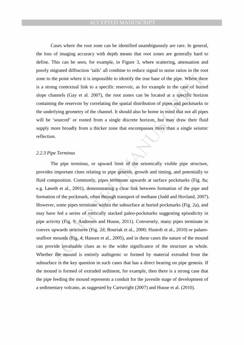
2.2.3 Pipe Terminus
The pipe terminus, or upward limit of the seismically visible pipe structure,
provides important clues relating to pipe genesis, growth and timing, and potentially to
fluid composition. Commonly, pipes terminate upwards at surface pockmarks (Fig. 8a;
e.g. Løseth et al., 2001), demonstrating a clear link between formation of the pipe and
formation of the pockmark, often through transport of methane (Judd and Hovland, 2007).
However, some pipes terminate within the subsurface at buried pockmarks (Fig. 2a), and
may have fed a series of vertically stacked paleo-pockmarks suggesting episodicity in
pipe activity (Fig. 9; Andresen and Huuse, 2011). Conversely, many pipes terminate in
convex upwards structures (Fig. 2d; Bouriak et al., 2000; Hustoft et al., 2010) or palaeo-
seafloor mounds (Fig. 4; Hansen et al., 2005), and in these cases the nature of the mound
can provide invaluable clues as to the wider significance of the structure as whole.
Whether the mound is entirely authigenic or formed by material extruded from the
subsurface is the key question in such cases that has a direct bearing on pipe genesis. If
the mound is formed of extruded sediment, for example, then there is a strong case that
the pipe feeding the mound represents a conduit for the juvenile stage of development of
a sedimentary volcano, as suggested by Cartwright (2007) and Huuse et al. (2010).
MANUSCRIP
T
ACCEPTED
ACCEPTED MANUSCRIPT
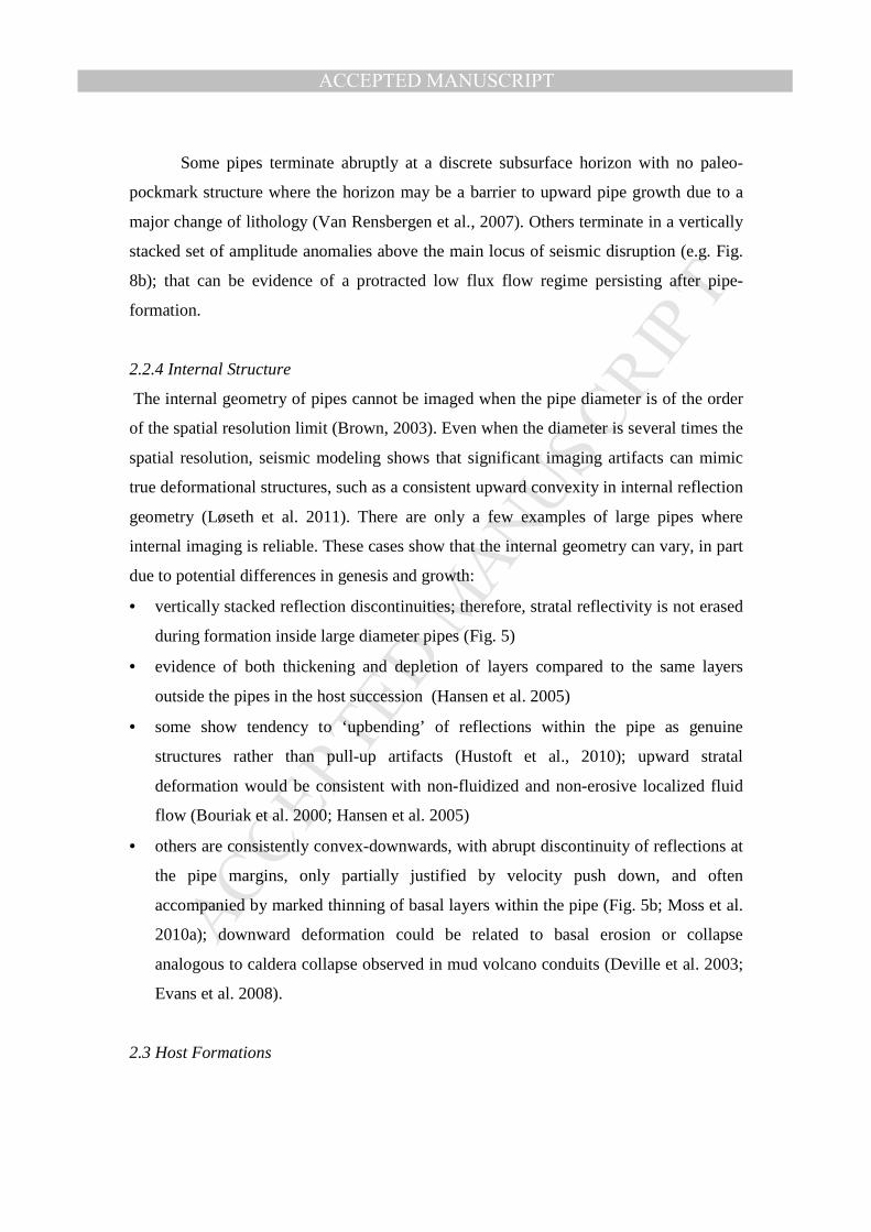
Some pipes terminate abruptly at a discrete subsurface horizon with no paleo-
pockmark structure where the horizon may be a barrier to upward pipe growth due to a
major change of lithology (Van Rensbergen et al., 2007). Others terminate in a vertically
stacked set of amplitude anomalies above the main locus of seismic disruption (e.g. Fig.
8b); that can be evidence of a protracted low flux flow regime persisting after pipe-
formation.
2.2.4 Internal Structure
The internal geometry of pipes cannot be imaged when the pipe diameter is of the order
of the spatial resolution limit (Brown, 2003). Even when the diameter is several times the
spatial resolution, seismic modeling shows that significant imaging artifacts can mimic
true deformational structures, such as a consistent upward convexity in internal reflection
geometry (Løseth et al. 2011). There are only a few examples of large pipes where
internal imaging is reliable. These cases show that the internal geometry can vary, in part
due to potential differences in genesis and growth:
• vertically stacked reflection discontinuities; therefore, stratal reflectivity is not erased
during formation inside large diameter pipes (Fig. 5)
• evidence of both thickening and depletion of layers compared to the same layers
outside the pipes in the host succession (Hansen et al. 2005)
• some show tendency to ‘upbending’ of reflections within the pipe as genuine
structures rather than pull-up artifacts (Hustoft et al., 2010); upward stratal
deformation would be consistent with non-fluidized and non-erosive localized fluid
flow (Bouriak et al. 2000; Hansen et al. 2005)
• others are consistently convex-downwards, with abrupt discontinuity of reflections at
the pipe margins, only partially justified by velocity push down, and often
accompanied by marked thinning of basal layers within the pipe (Fig. 5b; Moss et al.
2010a); downward deformation could be related to basal erosion or collapse
analogous to caldera collapse observed in mud volcano conduits (Deville et al. 2003;
Evans et al. 2008).
2.3 Host Formations
MANUSCRIP
T
ACCEPTED
ACCEPTED MANUSCRIPT
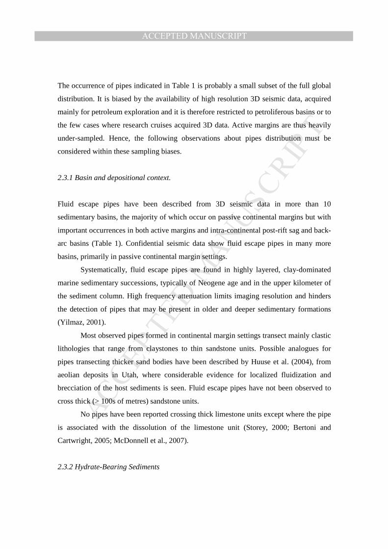
The occurrence of pipes indicated in Table 1 is probably a small subset of the full global
distribution. It is biased by the availability of high resolution 3D seismic data, acquired
mainly for petroleum exploration and it is therefore restricted to petroliferous basins or to
the few cases where research cruises acquired 3D data. Active margins are thus heavily
under-sampled. Hence, the following observations about pipes distribution must be
considered within these sampling biases.
2.3.1 Basin and depositional context.
Fluid escape pipes have been described from 3D seismic data in more than 10
sedimentary basins, the majority of which occur on passive continental margins but with
important occurrences in both active margins and intra-continental post-rift sag and back-
arc basins (Table 1). Confidential seismic data show fluid escape pipes in many more
basins, primarily in passive continental margin settings.
Systematically, fluid escape pipes are found in highly layered, clay-dominated
marine sedimentary successions, typically of Neogene age and in the upper kilometer of
the sediment column. High frequency attenuation limits imaging resolution and hinders
the detection of pipes that may be present in older and deeper sedimentary formations
(Yilmaz, 2001).
Most observed pipes formed in continental margin settings transect mainly clastic
lithologies that range from claystones to thin sandstone units. Possible analogues for
pipes transecting thicker sand bodies have been described by Huuse et al. (2004), from
aeolian deposits in Utah, where considerable evidence for localized fluidization and
brecciation of the host sediments is seen. Fluid escape pipes have not been observed to
cross thick (> 100s of metres) sandstone units.
No pipes have been reported crossing thick limestone units except where the pipe
is associated with the dissolution of the limestone unit (Storey, 2000; Bertoni and
Cartwright, 2005; McDonnell et al., 2007).
2.3.2 Hydrate-Bearing Sediments
MANUSCRIP
T
ACCEPTED
ACCEPTED MANUSCRIPT
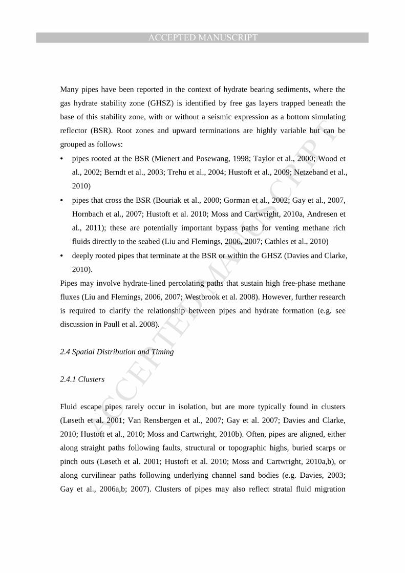
Many pipes have been reported in the context of hydrate bearing sediments, where the
gas hydrate stability zone (GHSZ) is identified by free gas layers trapped beneath the
base of this stability zone, with or without a seismic expression as a bottom simulating
reflector (BSR). Root zones and upward terminations are highly variable but can be
grouped as follows:
• pipes rooted at the BSR (Mienert and Posewang, 1998; Taylor et al., 2000; Wood et
al., 2002; Berndt et al., 2003; Trehu et al., 2004; Hustoft et al., 2009; Netzeband et al.,
2010)
• pipes that cross the BSR (Bouriak et al., 2000; Gorman et al., 2002; Gay et al., 2007,
Hornbach et al., 2007; Hustoft et al. 2010; Moss and Cartwright, 2010a, Andresen et
al., 2011); these are potentially important bypass paths for venting methane rich
fluids directly to the seabed (Liu and Flemings, 2006, 2007; Cathles et al., 2010)
• deeply rooted pipes that terminate at the BSR or within the GHSZ (Davies and Clarke,
2010).
Pipes may involve hydrate-lined percolating paths that sustain high free-phase methane
fluxes (Liu and Flemings, 2006, 2007; Westbrook et al. 2008). However, further research
is required to clarify the relationship between pipes and hydrate formation (e.g. see
discussion in Paull et al. 2008).
2.4 Spatial Distribution and Timing
2.4.1 Clusters
Fluid escape pipes rarely occur in isolation, but are more typically found in clusters
(Løseth et al. 2001; Van Rensbergen et al., 2007; Gay et al. 2007; Davies and Clarke,
2010; Hustoft et al., 2010; Moss and Cartwright, 2010b). Often, pipes are aligned, either
along straight paths following faults, structural or topographic highs, buried scarps or
pinch outs (Løseth et al. 2001; Hustoft et al. 2010; Moss and Cartwright, 2010a,b), or
along curvilinear paths following underlying channel sand bodies (e.g. Davies, 2003;
Gay et al., 2006a,b; 2007). Clusters of pipes may also reflect stratal fluid migration
MANUSCRIP
T
ACCEPTED
ACCEPTED MANUSCRIPT
pathways and the presence of traps, either due to underlying structure or to the presence
of gas hydrate seals at the base of the GHSZ (Nyegga area, offshore Norway - Weibull et
al., 2010).
2.4.2 Timing
The dating of pipe formation is poorly constrained. As image quality diminishes with
depth, many pipes may have complex growth histories concealed in poor image quality at
depth; furthermore, upward propagation may erase earlier evidence for pipe growth-
arrest at intermediate stages. Core-based isotope dating combined with high resolution
seismic data may overcome some of the present limitations in pipe dating (e.g., Plaza-
Faverola et al., 2010b). Guidelines frequently invoked in dating pipes using their seismic
expression include:
• a pipe termination at a seafloor pockmark suggests relatively recent pipe formation
(Løseth et al., 2001; Hustoft et al., 2010; Judd and Hovland, 2007).
• mound development at the upper terminus helps constrain the later stages of fluid
flow history as it contributes dateable materials at the top of the pipe (see discussion
in Mazzini et al. 2006; Hustoft et al. 2010)
• the seismic horizon that defines the stratigraphic position of upward pipe termination
does not necessarily define the time of pipe formation: it can instead be a sign of fluid
dissipation into a subsurface reservoir (Hustoft et al. 2007).
• episodic pipe growth is inferred where stacked pockmarks can be interpreted within a
single pipe structure (e.g. Fig. 9)(Andresen and Huuse, 2011); episodic formation
suggests protracted growth histories.
Of the numerous studies of pipe development presented to date, only two have
attempted systematic analysis of pipe formation times. Fluid escape pipes in the Nyegga
area, offshore Norway, were found to exhibit three formation stages (Plaza-Faverola et al.
2010a): (1) pipes that formed ~200kyrs ago and reactivated once or twice thereafter, with
a present day seafloor expression; (2) pipes that formed between 160 and 125kyrs,
without any present day seafloor expression; and (3) pipes that formed after the last
MANUSCRIP
T
ACCEPTED
ACCEPTED MANUSCRIPT
glacial maximum between 25 and 18kyrs ago. These periods of fluid escape correspond
to the last stages of glacial maxima in the region, when thick glacial debris flow deposits
led to loading-induced overpressures in the basin.
Significant diachroneity in pipe clusters was identified in the Namibe Basin offshore
Namibia over a 5-10Myr long period probably associated to cyclic excess pore pressure
generation and release (Moss and Cartwright, 2010b). A spatial statistical analysis of
pipe distributions in an area of intense pipe occurrence with a total population of nearly
400 pipes showed no preferential clustering patterns. Instead, pipe occurrence was found
to be sporadic (temporal resolution ~100-200ka), whereby pipes in one episode can form
in “virgin areas” with no previous pipes, or within the same area where clusters of pipes
had formed in previous episodes. However, newly formed pipes are not in close
proximity to pipes formed in an immediately preceding time period, suggesting the
underlying presence of an “exclusion distance” associated to fluid pressure build up.
An important consideration when attempting to date pipe formation, is the possibility
that some pipes may have formed in a syn-sedimentary mode (Fig. 10). It is possible that
some tall pipes may have grown by persistent or episodic fluid expulsion during
continued sedimentation, and the later propagation phases may then eradicate traces of
the earlier fluid expulsion (see Discussion).
3. Discussion: Pipe Genesis
Hypothetical mechanisms for pipe-genesis must be able to explain salient pipe
characteristics such as formation in layered clay-dominated sedimentary successions,
almost ubiquitous vertical orientation or geological ‘gravitropism,’ frequent association
with overpressured root zones, apparent exclusion distance between neighbouring pipes,
and varied termination conditions such as pockmarks, mounds and diffuse termination
within the sediment (Table 1). This section reviews previously suggested pipe formation
mechanisms, suggests two new potential mechanisms, and discusses their limitations.
3.1 Hydraulic Fracturing
MANUSCRIP
T
ACCEPTED
ACCEPTED MANUSCRIPT
Hydraulic fracture is frequently proposed to explain pipe formation (Løseth et al., 2001,
2011; Cartwright et al., 2007; Hustoft et al., 2007 and 2009; Moss and Cartwright 2010;
Plaza-Faverola et al., 2011; Davies et al., 2012). In this hypothesis, overpressure in the
root zone induces hydraulic fracturing in the overburden and a network of hydraulic
fractures propagates towards the surface normal to the minimum stress (Fig. 11). The
conditions necessary for hydraulic fracturing of ‘seal’ units above a source unit are
generally taken to be that the fluid pressure in the source should exceed the sum of the
minimum stress in the overburden plus the tensile strength (see Cosgrove (2001) for
review). The minimum stress may locally approach the overburden stress for poorly
consolidated, clay-rich overburden sediments with high values of K0 (the ratio between
horizontal and vertical effective stresses; Terzaghi et al. 1996). Hence, high values of
fluid overpressure in potential source units are a requirement for this mechanism to apply.
Some experimental work has been undertaken to evaluate the conditions
necessary for hydraulic fracturing of unconsolidated sediments as opposed to capillary
invasion (Fauria and Rempel, 2011), but it is more challenging to validate these
conditions in the subsurface. In this context, Seldon et al., (2003) and Reilly and
Flemings (2010) both argue in favour of fluid flow via networks of hydraulic fractures
and, importantly, document fluid pressures in shallow buried regional aquifers reaching
the minimum stress value at crestal regions where venting is observed. Trehu et al.
(2004) show that pressure in a gas column trapped beneath a vent is equal to the
overburden stress, and also argue for venting via hydraulic fracture networks.
Since fluid escape pipes are universally quasi-vertical, the development of pipes by this
mechanism would be favoured in regions where the maximum compressive stress is
vertical. A possible exception would be the case of a pipe that formed in an inclined
fracture and later migrated by gradual erosion to eventually align itself with the shortest
vertical path (see Ligtenburg, 2005). This mechanism is observed in laboratory scale
models, but migrating pipes erase the stratigraphy along their path.
The required overpressured zone can result from basinal hydrodynamics, build-up
of gas pressure due to organic matter evolution, hydrate dissociation or gas trapping at
hydrate seals beneath the gas hydrate stability zone (Flemings et al., 2003; Trehu et al.,
2004; Liu and Flemings, 2006), rapid glacial sediment loading (Hustoft et al., 2009), or
MANUSCRIP
T
ACCEPTED
ACCEPTED MANUSCRIPT
rapid loading by evaporate deposition (e.g. Bertoni et al. 2013)), amongst others.
Presence of methane as a free gas phase is commonly linked to pipe formation, and the
relatively modest gas column heights needed to fracture shallow sediments are widely
found in basins and may explain the preponderance of pipes with heights less than 200-
300m (Hornbach et al., 2004; Table 1). An interesting, and unresolved question however,
concerns the gas saturation required to (a) represent a continuous column, and (b) to
promote fracture propagation driven by the non-wetting (methane) as opposed to wetting
phase (pore water)(P. Flemings, Pers. Comm., 2014). Pipe genesis as hydraulic fractures
agrees with the spatial alignment of pipes relative to local structures such as hinges, folds
or minor faults that may affect the stress field, and transverse pipe ellipticity in some
cases (such as in Hustoft et al., 2010).
It is important to stress that there is thus far no direct evidence of hydraulic
fracturing within any in situ pipe observed on seismic data, possibly because of lack of
well calibration, so there may be lessons to be learned by analogy with outcropping pipes
or similar structures. At least one study has identified possible analogues to subsurface
fluid escape pipes on Rhodes (Greece) where circular fractures and brecciation are
observed (Løseth et al., 2011). It is also possible that exposed mud volcano conduits may
provide partial analogues for fluid escape pipes. It has been suggested, for example, that
the initial stages of formation of mud volcano conduits may be similar to the formation
of fluid escape pipes and that there may be a process continuum whereby fluid escape
pipes evolve into mud volcano conduits as the composition of the fluid evolves to include
solid componentsCartwright, 2007; Huuse et al. 2010). Outcropping mud volcano
conduits typically exhibit increased density of fracture networks towards the central
highly brecciated zone, and show evidence of mud slurry transport upwards via the
fracture network (Morley, 1997; Clari et al., 2004; Roberts et al., 2010).
It is less easy to draw analogies with vertical networks of sandstone intrusions
(formed by fluid pressure in a sand slurry mobilized from a highly overpressured
‘source’ sand body; Hurst and Cartwright, 2007). Outcrop studies of these networks
commonly show that aspect ratios of sandstone dykes are strongly elliptical in the
horizontal rather than closely grouped with vertical dimensions greater than the
horizontal (Vetel and Cartwright, 2010).
MANUSCRIP
T
ACCEPTED
ACCEPTED MANUSCRIPT
Arguments against the hydraulic fracture genesis of pipes relate to source zone
and pipe geometry. First, well imaged root zones show that many pipes do not initiate at
pressure foci such as structural crests of large anticlines or lateral pressure transfer zones
such as in updip pinchout positions (Fig. 3; Stump and Flemings 2000; Flemings et al.,
2003), but emanate from synclinal topographic lows or gently dipping layers with no
structural closure to build gas columns. Second, the hydraulic fracturing model is not
consistent with the slender columnar geometry observed for some pipes which may reach
a slenderness of Ω=20: it is mechanically unwarranted that individual fractures will
propagate from the root zone to the pipe terminus with such high aspect ratios. From this
perspective, the assumption that potential hydraulic fracture heights can be inferred from
compiled pipe height data remains highly questionable (Davies et al., 2012).
Fluid-driven erosion and flow localization along the vertical plane of hydraulic
fractures (Novikov and Slobodsky, 1978) could eventually evolve into a single pipe or
multiple aligned pipes with a proper exclusion distance between them (Ligtenburg, 2005).
Fluid-driven erosion is addressed next in the context of fluidization.
3.2 Erosive Fluidization
Fluidization is the mobilization of granular materials by seepage forces (Kunii and
Levenspiel, 1969; Lowe, 1975; Mourgues and Cobbold, 2003). Fluidization is a widely
observed phenomenon in geological systems (Woolsey, 1975; McCullum, 1985; Nichol,
1995), and has been invoked in association with the formation of pockmarks, mud
volcanoes, hydrothermal vent complexes and kimberlite pipes (Lorenz, 1975; Brown,
1990; Nermoen et al., 2010). In fact, small-scale experimental studies have shown that
the typically upwards-widening, steep, conical structure of diatremes or hydrothermal
vent complexes can be reproduced in the laboratory by fluidization of a granular medium
under a high pressure input jet of water or air (Fig. 12)(Woolsey, 1975; McCullum, 1985;
Nichol, 1995; Nermoen et al., 2010). Pressure dependent fluid expansion (e.g., gas
exsolution or steam expansion) increases the efficiency of fluidization, as observed in
multiphase magmatic eruptions, diatremal structures and kimberlites (Woolsey, 1975;
McCullum, 1985), and is considered responsible for the development of pockmarks
(Judd and Hovland, 2007). Furthermore, fluid-pressure driven pipe formation may
MANUSCRIP
T
ACCEPTED
ACCEPTED MANUSCRIPT
explain clustering patterns and exclusion distance between pipes determined by lateral
drainage efficiency within the overpressured zone (Moss et al., 2010b).
While fluidization can capture some of the final characteristics of some localized
flow structures, this model does not explain initiation conditions. In particular, the
necessary flow velocity for fluidization will not develop in layered sedimentary columns
where low permeability, fine-grained layers hinder fluid flow, even when overpressure
develops in underlying high permeability reservoirs (Fig. 12c). In fact, an initiation
mechanism such as hydraulic fracturing is needed prior to flow localization and
fluidization pipe formation to provide the critical flow velocity needed for fluidization in
the overburden. Alternative, retrogressive top-down piping can develop in a fluidized bed
when the hydraulic gradient (the difference in hydraulic head between the source layer
and the outlet divided by the length) exceeds 1.0 and flow localization nucleates at
preferential points (Note: higher gradients will be needed in partially lithified sediments).
Retrogressive erosion (from the exit to the source) is a well-known pipe formation
mechanism beneath dam failures (Terzaghi et al 1996), and only requires a high
hydraulic gradient across a permeable granular medium for flow localization to emerge.
We highlight that flow localizes at the outlet which would be the seabed in the case of
pipes from where the pipe would then propagate downwards towards the overpressured
source.
Clearly, erosive fluidization cannot explain pipes with a diffuse upper termination
within the sediment column (e.g. Fig. 8b). In addition, internal erosion would erase the
layered stratigraphy of the host medium that is seismically observed within the pipe (Fig.
12)(McCullum, 1985; Nermoen et al., 2010). Therefore, erosive fluidization cannot
explain the genesis of pipes that exhibit clear stratigraphic continuity across the full
width of pipes as observed using high resolution seismic data where the wavelength is
much smaller than the pipe diameter (e.g. Figs 1, 5 & 6). Top-down piping is also
unlikely to explain cases where there are strong orientational controls on pipe distribution
exerted by underlying source layers such as submarine channels (e.g. Davies, 2003).
3.3 Capillary invasion
MANUSCRIP
T
ACCEPTED
ACCEPTED MANUSCRIPT
Gas migrates through water-saturated sediments when the difference between the gas
pressure pg and the water pressure pw exceeds the capillary entry pressure (similar to
capillary trapping in petroleum reservoirs Schowalter, 1979; Watts, 1987; Berg, 1975).
From Laplace’s equation:
rcos2
pp wg
θγ≥−
where γ is interfacial tension, θ is contact angle and r is the effective pore throat radius.
The pressure difference is determined by the height of the continuous gas column Hg, and
differences in unit weights γw and γg,
( )gwgwg Hpp γ−γ=−
Capillary invasion has been suggested as a mechanism for pipe formation when
the root zone can generate free phase gas (e.g. Liu and Flemings, 2006, 2007). A recent
model links pipe formation (although termed gas chimneys by the authors) to pockmark
formation using the process of capillary invasion (Cathles et al., 2010). In this model, gas
trapped at a capillary seal accumulates up to a critical thickness until the buoyancy at the
top of the seal forces the gas through the pore throats at which point it forms, an upward
migrating gas column that advances as a piston and displaces pore fluiden route (Fig. 13).
Cathles et al., (2010) suggest that pipe growth will be controlled by capillary barriers in
the overburden (bedding), which give the chimney a relatively flat topped geometry and
limit its width. They argue that the diameter of the chimney will be controlled by the
sediment heterogeneity and envisage that gas will saturate the pore space in the chimney
and thus move easily through it with little viscous resistance. They argue that pockmarks
form when the pipe extends about halfway to the seafloor from the source layer (Fig.
13a-c) and final expansion of gas at the seafloor results in a final more dramatic stage of
pockmark formation (Fig. 13d).
MANUSCRIP
T
ACCEPTED
ACCEPTED MANUSCRIPT
The most positive feature of this model is that it offers a logical explanation for
the classic columnar, vertical geometry of pipes, based on the buoyancy of the free gas
phase. A pre-requisite of the model is therefore the existence of a gas column of
sufficient height to initiate capillary failure of the seal. However, for many pipes
observed on seismic, particularly those emanating from synclinal positions, or from
simple monoclinal flanks, the trap configuration does not easily equate with the
necessary column height requirements.
How realistic is a piston like capillary invasion, upwards through highly
heterogeneous sediments typical of many successions hosting observed fluid escape
pipes? Pipe growth by capillary invasion is hindered by fine-grained layers with small
pore-size. In relatively homogeneous sediments, lateral spread against finer layers will
control the effective diameter of pipes. However, vertical permeability heterogeneity can
be several orders of magnitude between alternating layers typically found in marine
hemipelagic depositional settings where pipes are observed (Yang and Aplin, 1998). In
this case, gas invasion will more likely take the form of stacked ‘pancake’ or ‘Christmas
tree’ topology (Fig. 14) of a type observed during CO2 injection in the long term
sequestration project in Norway (Arts et al. 2004), rather than the universally columnar
geometry exhibited by pipes (Figs. 1-5). Recent observations of highly irregular
vertically stacked amplitude anomalies are also good examples of what might be more
typically expected from upward gas migration by capillary invasion of a multilayered
stratigraphy (Foschi et al., 2014).
Note that the formation of a preferential gas migration pathway does not
necessarily imply any deformation of the layered stratigraphy which are observed in
high-resolution seismic images of pipes, e.g., layer distortion, pinching and sagging.
While specifically excluded in Cathles et al., (2010) analysis, gas-driven opening mode
discontinuities may emerge during gas invasion (Jain and Juanes, 2009; Shin and
Santamarina, 2010 & 2011; Fauria and Rempel, 2011).
MANUSCRIP
T
ACCEPTED
ACCEPTED MANUSCRIPT
3.4 Localized subsurface volume loss
Localized subsurface volume loss causes a pipe-shaped collapse geometry in the
overburden with slenderness ratios comparable to many pipes reviewed here (Whittaker
and Reddish, 1989). Contrary to erosive fluidization, pipes generated by local volume
loss preserve the initial stratigraphy, albeit layers appear down-shifted (Fig. 15; Qiliang
et al., 2013). Collapse of the initial void propagates upwards in a columnar zone of
fracturing that significantly enhances the vertical permeability of the overburden and
promotes fluid escape preferentially via the pipe (McDonnell et al., 2007). Mineral
deposits are frequently encountered in these structures which when mineralised are
commonly termed breccia pipes.
Subsurface volume loss can result from the dissolution of carbonate or evaporites
(Bertoni and Cartwright, 2006; Cartwright et al. 2007; McDonnell et al., 2007; Qiliang et
al., 2013), hydrate dissociation (augmented by gas expansion and migration), or even
organic matter degradation. Many pipes have been observed within the gas hydrate
stability zone (Moss et al., 2010a; Davies and Clark, 2010). An important difference
between this mechanism and that of hydraulic fracture, capillary invasion or erosive
fluidisation is that no initial overpressure condition is specifically required in the ‘source’
unit i.e. the unit undergoing volume loss, although such overpressure may exist.
In unconsolidated sediments, these pipes may be delimited by sharp shear
localization along peripheral walls, stress relaxation within the pipe, and sediment
expansion and loosening within the pipe (Cha, 2012). When sediments have experienced
some degree of lithification the upward propagation may evolve as successive roof
collapse events. This “stoping” mechanism has been suggested for the formation of mud
volcano conduits (Roberts et al., 2010).
3.5 Syn-sedimentary Formation
A compacting basin sustains upwards fluid flow. The flow field is not necessarily
uniform, and often localizes into a few drainage paths as new sediments are deposited.
Localized flow may be preserved during sedimentation. This is the case when sediments
MANUSCRIP
T
ACCEPTED
ACCEPTED MANUSCRIPT
have a broad grain size distribution or the depositional sequence consists of successive
fine-coarse grained layers: drag forces drive fine-grains away from the injection point
and form an aquitard layer concentrically away from the flow field. In the meantime,
coarser grains fill the space above the injection point. As sedimentation continues, a
highly conductive syn-sedimentary pipe made of the coarser fraction is formed (Fig. 10).
In contrast, syn-sedimentary pipe formation is not expected in homogeneous
media made of uniform grain size sediments, as the pressure field decays rapidly away
from the injection point. This fluid-dependent overpressure release genesis underlies self-
regulation between sedimentation and fluid pressure.
Many tall pipes may have started their evolution as short pipes, and grown
upwards as sedimentation occurs. Dating of syn-sedimentary pipes should rely on
detecting thickness changes or segregation attributes within the main conduit.
Syn-sedimentary pipes may end within the sedimentary column as fluids leak-off
the main conduit and lower velocities cannot drag fine grains away. Similar to
fluidization, syn-sedimentary pipes prevent the formation of fine grain layers within the
pipe; however, grains coarser than the Stokes grain size may form layers within pipes.
4. Concluding Remarks
Pipes are remarkable features that can exert a controlling role in the overall subsurface
geo-plumbing. The salient characteristics of pipes include: favoured in layered, clay-
dominated sedimentary basins, development in either in a single formation event or in
episodic formation; decisive vertical orientation; may exhibit pronounced slenderness
ratios Ω=10 or greater; often linked to high-pressure root zones (sometimes related to gas
accumulation) or collapse structures; possible regional clustering; alignment may reflect
subsurface features; termination my take place at the seafloor (pockmarks or mounds) or
within the sediment (paleo-pockmarks or in diffuse termination); and, the structure of the
host sediment may be preserved within the pipe (at least in large pipes).

MANUSCRIP
T
ACCEPTED
ACCEPTED MANUSCRIPT
Not all pipes are made equal! Furthermore, it is important to distinguish between
initiation and growth mechanisms. Indeed, field evidence suggests several genetic
processes at work. Therefore, it may be unwarranted to assume that all pipes form in a
single, catastrophic phase of fluid expulsion from a deep, highly overpressured source
region.
Hypothetical formation mechanisms must be able to explain salient
characteristics identified above. The frequently invoked hypothetical genesis by
hydraulic fracture cannot explain the most common features observed in most pipes.
However, it may be an initiator to pipe formation, but followed by flow localization and
erosive fluidization. These processes can be augmented by capillary effects related to gas
phase accumulations, gas exsolution and expansion. There is clear evidence that some
pipes form as the overburden collapses above a localized zone of volume contraction.
Other pipes may have developed by a syn-sedimentary process, growing vertically during
prolonged joint phases of fluid escape and continual sedimentation.
Observations summarized in this review are hampered by problems related to
seismic imaging of vertical structures, where lateral and vertical seismic velocity
anomalies are present. This leads to considerable uncertainty in the true structure of pipes,
with many potential artefacts contributing to the seismic appearance of pipes. Analogues
such as mud volcano conduits may provide valuable insight into these potentially
important fluid escape pathways.
This review has focused primarily on synthesising seismic observations of pipes,
and assessing potential genetic mechanisms in that context. If additional constraints are
available for the composition of the fluids transported through the pipe at the time of
formation, e.g. from direct seafloor sampling (e.g. Smith et al. 2014), associated
diagenetic phenomena at the vent (e.g. Gay et al. 2006b), or from rock physical
calibrations of associated direct hydrocarbon indicators such as acoustically soft
amplitude anomalies (Foschi et al. 2014), then it may be possible to narrow down the
range of potential mechanisms further on a case by case basis.
Finally, it seems likely that fluid escape pipes are far more common in
sedimentary basins than the current limited literature on the subject suggests. The pipe
structures represent a clear manifestation of natural flow localization phenomena at a
MANUSCRIP
T
ACCEPTED
ACCEPTED MANUSCRIPT
range of scales, and may be integral to many hydrocarbon plumbing systems in
petroliferous basins worldwide.
5. References
Andresen, K.J., Huuse, M., Schodt, N.H., Clausen, L.F., Seidler, L. 2011. Hydrocarbon
plumbing systems of salt minibasins offshore Angola revealed by three-dimensional
seismic analysis. American Association of Petroleum Geologists Bulletin, 95, 1039-
1065.
Andresen, K.J. Huuse, M. 2011. ‘Bulls-eye’ pockmarks and polygonal faulting in the
lower Congo Basin: Relative timing and implications for fluid expulsion during shallow
burial. Marine Geology, 279, 111-127.
Arts, R, Eiken, O., Chadwick, A., Zweigel, P., van der Meer, B., Kirby, J., 2004. Seismic
monitoring of the Sleipner underground CO2 storage site (North Sea): In Baines, S.J.,
Worden, R.H. (Eds), Geological Storage of Carbon Dioxide. Geological Society of
London Special Publication, 233, 181-191.
Baas, J.H., Mienert, J., Schultheiss, P., Evans, D., 1994. Evidence of gas vents and gas
hydrates in the Storegga Slide area. Abstracts, Gas in Marine Sediments, 3rd International
Conference, NIOZ, Texel, The Netherlands, September, 1994.
Bacon, M., Simm, R, Redshaw, T., 2007. 3D Seismic Interpretation. Cambridge
University Press. pp. 238.
Berg, R.R. 1975. Capillary pressures in stratigraphic traps. American Association of
Petroleum Geologists Bulletin, 59, 939-956.
MANUSCRIP
T
ACCEPTED
ACCEPTED MANUSCRIPT
Berndt, C., Bunz, S., Mienert, J., 2003. Polygonal fault systems on the mid-Norwegian
margin: a long-term source for fluid flow. In: Van Rensbergen, P., Hillis, R.R., Morley,
C.K. (Eds), Subsurface Sediment Mobilization, Geological Society of London, Special
Publication, 216, 283-290.
Berndt, C., 2005. Focused fluid flow in passive continental margins. Philosophical
Transactions of the Royal Society, A, 363, 2855-2871.
Bertoni, C., Cartwright, J.A., 2005. 3D seismic analysis of circular evaporite dissolution
structures, Eastern Mediterranean. Journal of the Geological Society, 162, 909-926.
Bertoni, C., Cartwright, J. and Hermanrud, C., 2013. Evidence for large-scale methane
venting due to rapid drawdown of sea level during the Messinian Salinity Crisis.
Geology 41 (3), 371-374.
Bouriak, S., Vanneste, M., Saoutkine, A., 2000. Inferred gas hydrates and clay diapirs
near the Storegga Slide on the southern edge of the Voring Plateau, Norway. Marine
Geology, 163, 125-148.
Brown, K.M., 1990. The nature and hydrogeological significance of mud diapirs and
diatremes for accretionary systems, Journal of Geophysical Research, 95, 8969-8982.
Brown, A. R., 2003. Interpretation of three dimensional seismic data. 6th edition,
American Association of Petroleum Geologists, Memoir 42.
Bünz, S., Mienert, J., Berndt, C., 2003. Geological controls on the Storegga gas-hydrate
system of the mid-Norwegian continental margin: Earth and Planetary Science Letters,
209, 291-307.
Cartwright, J.A. 2007. The impact of 3D seismic on modeling fluid flow in sedimentary
basins. Journal of the Geological Society of London, 164, 881-893.
MANUSCRIP
T
ACCEPTED
ACCEPTED MANUSCRIPT
Cartwright, J., Huuse, M., Aplin, A., 2007. Seal bypass systems. American Association
of Petroleum Geologists Bulletin, 91, 1141-1166.
Cathles, L.M., Su, Z., Chen, D., 2010. The physics of gas chimney and pockmark
formation, with implications for assessment of seafloor hazards and gas sequestration.
Marine and Petroleum Geology, 27, 82-91.
Cha, M, 1992. Mineral dissolution in sediments. PhD Thesis, Georgia Institute of
Technology, Atlanta, USA, pp152.
Clari, P., Cavagna, S., Martire, L., Hunziker, J., 2004. A Miocene mud volcano and its
plumbing system: a chaotic complex revisited (Monferrato, NW Italy). Journal of
Sedimentary Research, 74, 662-676.
Cosgrove, J., 2001. Hydraulic fracturing during the formation and deformation of a
basin: A factor in the dewatering of low-permeability sediments. American Association
of Petroleum Geologists Bulletin, 85, 737-748.
Davies, R. J., 2003. Kilometer-Scale fluidization structures formed during early burial of
a deepwater slope channel on the Niger Delta. Geology, 31, 949-952.
Davies, R.J., Clarke, A.L., 2010. Methane recycling between hydrate and critically
pressured stratigraphic traps, offshore Mauretania. Geology, 38, 963-966.
Davies, R.J., Mathias, S.A., Moss, J., Hustoft, S., Newport, L., 2012. Hydraulic fractures:
how far can they go? Marine and Petroleum Geology 37, 1-6.
Deville, E., Battani, A. Griboulard, R., Guerlais, S., Herbin, J.P., 2003, The origin and
processes of mud volcanism: new insights from Trinidad, In: Van Rensbergen, P, Hillis,
MANUSCRIP
T
ACCEPTED
ACCEPTED MANUSCRIPT
R., Morley, C. (Eds), Subsurface Sediment Mobilisation, Geological Society, London
Special Publication, 216, 475-490.
Dewhurst, D.N., Yang, Y., Aplin, A., 1999. Permeability and fluid flow in natural
mudstones. In: Fleet, A.J., MacQuaker, J.H.S (Eds), Muds and Mudrocks: Physical and
Fluid Flow Properties. Geological Society of London Special Publication, 23-44.
Evans, D., King, E.I., Kenyon, N.H., Brett, C., Wallis, D., 1996. Evidence for long term
instability in the Storegga Slide region off western Norway. Marine Geology, 130, 281-
292.
Evans, R.J., Stewart, S.A., Davies, R.J., 2008. The structure and formation of mud
volcano summit calderas. Journal of the Geological Society of London, 165, 769-780.
Fauria, K. E., Rempel, A. W., 2011. Gas invasion into water-saturated, unconsolidated
porous media: Implications for gas hydrate reservoirs. Earth and Planetary Science
Letters, v. 312, (1-2), 188-193.
Fisher, K., Warpinski, N., 2011. Hydraulic fracture-height growth: Real data. Society of
Petroleum Engineers, paper 145949.
Flemings, P.B., Liu, X., Winters, W.J., 2003. Critical pressure and multiphase flow in
Blake Ridge gas hydrates. Geology, 31, 1057-1060.
Foschi, M., Cartwright, J.A., Peel, F.J., 2014. Vertical anomaly clusters: Evidence for
vertical gas migration across multilayered sealing sequences. American Association of
Petroleum Geologists Buleltin, 98 (9), 1859-1884. doi: 10.1306/04051413121
Gay, A., Lopez, M., Cochonat, P., Séranne, M., Levaché, D., Sermondadaz, G., 2006a.
Isolated seafloor pockmarks linked to BSRs, fluid chimneys, polygonal faults and
MANUSCRIP
T
ACCEPTED
ACCEPTED MANUSCRIPT
stacked Oligocene-Miocene turbiditic palaeochannels in the Lower Congo Basin. Marine
Geology, 226, 25-40.
Gay, A., Lopez, M., Cochonat, P., Levaché, D., Sermondadaz, G., Seranne, M., 2006b.
Evidences of early to late fluid migration from an upper Miocene turbiditic channel
revealed by 3D seismic coupled to geochemical sampling within seafloor pockmarks,
Lower Congo Basin. Marine and Petroleum Geology, 23, 387-399.
Gay, A., Lopez, M., Berndt, C., Seranne, M., 2007. Geological controls on focused fluid
flow associated with seafloor seeps in the Lower Congo Basin. Marine Geology, 244, 68-
92.
Gorman, A. R., Holbrook, W.S., Hornbach, M.J., Hackwith, K.L., 2002. Migration of
methane gas through the hydrate stability zone in a low-flux hydrate province, Geology
30, 327-330.
Hansen, J. P. V., Cartwright, J., Huuse, M., Clausen, O. R. 2005. 3D seismic expression
of fluid migration and mud remobilization on the Gjallar Ridge, offshore mid Norway.
Basin Research, 17, 123-139.
Hornbach, M.J., Saffer, D.M., Holbrook, S.W., 2004. Critically pressured free-gas
reservoirs below gas-hydrate provinces. Nature, 427, 142-144.
Hornbach, M.J., Ruppel, C., Van Dover, C.L., 2007. Three-dimensional structure of fluid
conduits sustaining an active deep marine cold seep: Geophysical Research Letters, 34
(3), L05601.
Hovland, M, Judd, A. G. 1988. Seabed Pockmarks and Seepages - Impact on Geology,
Biology and the Marine Environment. Graham & Trotman, London.
MANUSCRIP
T
ACCEPTED
ACCEPTED MANUSCRIPT
Hurst., A., Cartwright, J.A., 2007. Relevance of sand injectites to hydrocarbon
exploration and production. American Association of Petroleum Geologists Memoir 87,
1-20.
Hustoft, S., Mienert, J., Bünz, S., Nouze, H., 2007. High-resolution 3D-seismic data
indicate focussed fluid migration pathways above polygonal fault systems of the mid-
Norwegian margin: Marine Geology, v. 245, 89-106.
Hustoft, S., Dugan, B., Mienert, J., 2009. Effects of rapid sedimentation on developing
the Nyegga pockmark field: constraints from hydrological modeling and 3-D seismic
data, offshore mid-Norway. Geochemistry, Geophysics, Geosystems, 10,
doi:10.1029/2009GC002409.
Hustoft, S., Bünz, S., Mienert, J., 2010. Three-dimensional seismic analysis of the
morphology and spatial distribution of chimneys beneath the Nyegga pockmark field,
offshore mid-Norway. Basin Research 22, 465-480.
Huuse, M., Shoulders, S., Netoff, D., Cartwright, J.A., 2005. Giant sandstone pipes
record basin scale liquefaction of dune sands in the Middle Jurassic of SE Utah. Terra
Nova, 17, 80-85. doi: 10.1111/j.1365-3121.2004.00587.x
Huuse, M., Van Rensbergen, P., Jackson, C.A.L., Flemings, P.B., Davies, R.J., Dixon,
R.J. 2010. Subsurface sediment remobilisation and fluid flow in sedimentary basins:
preface. Basin Research, 22, 341-360.
Jain, A.K., Juanes, R. 2009. Preferential mode of gas invasion in sediments: grain-scale
mechanistic model of coupled multiphase fluid flow and sediment mechanics. Journal of
Geophysical Research, 114, B08101. Doi: 10.1029/2008JB006002.
Judd, A.G., Hovland, M., 2007, Seabed fluid flow: The impact on geology, biology and
the marine environment: Cambridge, Cambridge University Press.
MANUSCRIP
T
ACCEPTED
ACCEPTED MANUSCRIPT
Kopf, A., 2002. Significance of mud volcanism: Reviews of Geophysics, 40, 1005-1034.
Kunii, D., Levenspiel, O., 1969. Fluidisation Engineering, Butterworth, London.
Ligtenberg, J.H., 2005. Detection of Fluid migration pathways in seismic data:
Implications for fault seal analysis. Basin Research, v. 17, 141-153.
Liu, X., Flemings, P.B., 2006. Passing gas through the hydrate stability zone at Hydrate
Ridge, offshore Oregon. Earth and Planetary Science Letters, 241, 211-226.
Liu, X., Flemings, P.B., 2007. Dynamic multiphase flow model of hydrate formation in
marine sediments: Journal of Geophysical Research B: Solid Earth, 112, B03101, doi:
10.1029/2005JB004227.
Lorenz, V., 1975. Formation of phreatomagmatic maar-diatreme volcanoes and its
relevance to kimberlite diatremes. Physics and Chemistry of the Earth, 9, 17-27.
Løseth, H., Wensaas, L., Arntsen, B., Hanken, N., Basire, C., Graue, K., 2001. 1000m
long gas blow out pipes: 63rd EAGE Conference and Exhibition, Extended Abstracts, p.
524.
Løseth, H., Wensaas, L., Arntsen, B., Hanken, N-M., Basire, C., Graue, K., 2011. 1000m
long gas blow out pipes. Marine and Petroleum Geology, 28, 1047-1060.
Lowe, D.R., 1975. Water escape structures in coarse grained sediments. Journal of
Sedimentary Petrology, 44, 484-501.
McCallum, M.E., 1985. Experimental evidence for fluidization processes in breccia pipe
formation. Economic Geology, 80, 1523-1543.
MANUSCRIP
T
ACCEPTED
ACCEPTED MANUSCRIPT
McDonnell, A., Loucks, R.G. Dooley, T., 2007. Quantifying the origin and geometry of
circular sag structures in northern Fort Worth Basin, Texas: Paleocave collapse, pull-
apart fault systems, or hydrothermal alteration? American Association of Petroleum
Geologists Bulletin, 91, 1295-1318.
Mandl, G., Harkness, R.M., 1987. Hydrocarbon migration by hydraulic fracturing. In:
Jones, M.E., Preston, R.M.F. (eds), Deformation of Sediments and Sedimentary Rocks,
Geological Society of London Special Publication 29, 39-53.
Mazzini, A., Svensen, H., Hovland, M., Planke, S.. 2006. Comparison and implications
from strikingly different authigenic carbonates in a Nyegga complex pockmark, G11,
Norwegian Sea. Marine Geology, 231, 89-102.
Mienert, J., Posewang, J., 1999. Evidence of shallow- and deep-water gas hydrate
destabilizations in North Atlantic polar continental margin sediments: Geo-Marine
Letters, v. 19, 143-149.
Morley, C.K., Crevello, P., Ahmad, Z.H., 1998. Shale tectonics associated with active
diapirism: The Jerudong Anticline, Brunei Darussalam. Journal of the Geological Society
of London, 155, 475-490.
Moss, J.L., Cartwright, J., 2010a, 3D seismic expression of Km-scale fluid escape pipes
from offshore Namibia. Basin Research, 22, 481-502.
Moss, J.L., Cartwright, J.A., 2010b. The spatial and temporal distribution of pipe
formation, offshore Namibia. Marine and Petroleum Geology, 27, 1216-1234.
doi:10.1016/j.marpetgeo.2009.12.013
Mourgues, R., Cobbold, P., 2003. Some tectonic consequences of fluid overpressures
and seepage forces as demonstrated by sandbox modelling. Tectonophysics, 376, 75-97.
MANUSCRIP
T
ACCEPTED
ACCEPTED MANUSCRIPT
Nermoen, A., Galland, O., Jettestuen, E., Fristad, K., Podlachikov, Y., Svensen, H.,
Malthe-Sorensen, A., 2010. Experimental and analytical modeling of piercement
structures. Journal of Geophysical Research, 115, B10202, doi:10.1029/2010JB007583.
Netzeband, G.L., Krabbenhoeft, A., Zillmer, M., Papenberg, C. Bialas, J., 2010. The
structures beneath submarine methane seeps: seismic evidence from Opouawe Bank,
Hikurangi Margin, New Zealand. Marine Geology, 272, 59-70.
Nichols, R. J., Sparks, R. S. J., Wilson, C. N. J., 1994. Experimental studies of the
fluidization of layered sediments and the formation of fluid escape structures.
Sedimentology, 41, 233-253.
Novikov, L.A., and Slobodskoy, R.M., 1978, Mechanism of formation of diatremes:
International Geology Review, 21, no.10.
Paull, C.K., Ussler Iii, W., Holbrook, W.S., Hill, T.M., Keaten, R., Mienert, J.,
Haflidason, H., Johnson, J.E., Winters, W.J., Lorenson, T.D., 2008. Origin of pockmarks
and chimney structures on the flanks of the Storegga Slide, offshore Norway. Geo-
Marine Letters, 28, 43-51.
Plaza-Faverola, A., Bünz, S., Mienert, J., 2010a. Repeated fluid expulsion through sub-
seabed chimneys offshore Norway in response to glacial cycles. Earth and Planetary
Science Letters, 305, 297-308.
Plaza-Faverola, A., Bünz, S., Mienert, J., 2010b. Fluid distributions inferred from P-
wave velocity and reflection seismic amplitude anomalies beneath the Nyegga pockmark
field on the mid-Norwegian margin. Marine and Petroleum Geology, 27, 46-60.
Qiliang, S., Cartwright, J., Wu, S. and Chen, D. 2013. 3D seismic interpretation of
dissolution pipes in the South China Sea: Genesis by subsurface, fluid induced collapse.
Marine Geology, 337, 171-181.
MANUSCRIP
T
ACCEPTED
ACCEPTED MANUSCRIPT
Reilly, M. J., and Flemings, P. B., 2010. Deep pore pressures and seafloor venting in the
Auger Basin, Gulf of Mexico. Basin Research, 22, 380-397.
Roberts, K.S., Davies, R.J., Stewart, S., 2010. Structure of exhumed mud volcano feeder
complexes, Azerbaijan. Basin Research. 22, 439-451.
Seldon, B., Flemings, P. B., and Sawyer, D., 2003, Reservoir Pressure and Sea Floor
Venting: Predicting trap integrity in a Gulf of Mexico deepwater turbidite minibasin,
Abstract, AAPG International Conference: Barcelona, Spain.
Shin, H., Santamarina, J.C., 2010. Fluid driven fractures in uncemented sediments:
Underlying particle-level processes. Earth and Planetary Science Letters, 299, 180-189.
Shin, H., Santamarina, J.C., 2011. Open-mode discontinuities in soils. Geotechnique
Letters, 1, 95-99.
Showalter, T.T., 1979. Mechanisms of secondary hydrocarbon migration and
entrapment. American Association of Petroleum Geologists Bulletin, 63, 723-760.
Smith, A. J., Flemings, P. B., and Fulton, P. M., 2014a, Hydrocarbon flux from natural
deepwater Gulf of Mexico vents. Earth and Planetary Science Letters, 395, 241-253.
Storey, C., Peng, P., Lin, J.D., 2000. Liuhua 11-1 Field, South China Sea: a shallow
carbonate reservoir developed using ultrahigh-resolution 3-D seismic, inversion, and
attribute-based reservoir modeling. In: 32nd Annual offshore technology conference
transactions, Houston, pp. 1-11.
MANUSCRIP
T
ACCEPTED
ACCEPTED MANUSCRIPT
Stump, B., Flemings, P.B., 2000. Overpressure and fluid flow in dipping structures of the
offshore Gulf of Mexico (E.I. 330 field). Journal of Geochemical Exploration, 69-70, 23-
28.
Svensen, H., Planke, S., Malthe-Sorensen, A., Jamtveit, B., Myklebust, R Eiden, T.R.
Rey, S.S., 2004. Release of methane from a volcanic basin as a mechanism for initial
Eocene global warming. Nature, 429, 542-544.
Taylor, M.H., Dillon, W.P., and Pecher, I.A., 2000. Trapping and migration of methane
associated with the gas hydrate stability zone at the Blake Ridge Diapir: New insights
from seismic data. Marine Geology, 164, 79-89.
Terzaghi, K, Peck, R, Mesri, G., 1996. Soil Mechanics in Engineering Practice, 3rd
Edition, Wiley, London, UK. p 592.
Tréhu, A.M., Flemings, P.B., Bangs, N.L., Chevallier, J., Gràcia, E., Johnson, J.E., Liu,
C.-S., Liu, X., Riedel, M., Torres, M.E., 2004. Feeding methane vents and gas hydrate
deposits at South Hydrate Ridge. Geophysical Research Letters, 31, 1-4.
Tsvankin, I., Gaiser, J., Grechka, V., v.d. Baan, M., Thomsen, L., 2010. Seismic
anisotropy in exploration and reservoir characterization: a review. Geophysics, 75,
75A15-75A29.
Van Rensbergen, P., Rabaute, A., Colpaert, A., Ghislain, T.S., Mathijs, M., and
Bruggeman, A., 2007, Fluid migration and fluid seepage in the Connemara field,
porcupine basin interpreted from industrial 3D seismic and well data combined with
high-resolution site survey data. International Journal of Earth Sciences, 96, 185-197.
Vetel, W., and Cartwright, J.A. 2010. Emplacement mechanics of sandstone intrusions:
insights from the Panoche Giant Intrusion Complex, California. Basin Research, 22, 783-
807.doi: 10.1111/j.1365-2117.2009.00439.x
MANUSCRIP
T
ACCEPTED
ACCEPTED MANUSCRIPT
Watts, N.L., 1987. Theoretical aspects of cap-rock and fault seals for single- and two-
phase hydrocarbon columns. Marine and Petroleum Geology, 4, 274-307.
Westbrook, G, Exley, R., Minshull, T., Nouze, H., Gailler, A., Jose, T., Ker, S., Plaza-
Faverola, A. 2008. High resolution 3D seismic investigations of hydrate bearing fluid-
escape chimneys in the Nyegga region of the Voring Plateau, Norway. Proceedings of
the 6th International Conference on Gas Hydrates, Vancouver, Canada.
Weibull, W., Mienert, J., Bünz, S., Hustoft, S., 2010. Fluid migration directions inferred
from gradient of time surfaces of the sub seabed. Marine and Petroleum Geology, 27,
1898-1909.
Whittaker, B. N., Reddish, D. J., 1989. Subsidence: Occurrence, Prediction and Control,
Elsevier Science Publishing Company Inc., New York. pp 324.
Woolsey, T.S., McCallum, M.E., Schumm, S.A., 1975., Modelling of diatreme
emplacement by fluidization. Physics and Chemistry of the Earth, 9, 29-42.
Yang, Y., Aplin A., 1998. Influence of lithology and compaction on the pore size
distribution and modelled permeability of some mudstones from the Norwegian margin,
Marine and Petroleum Geology, 15, 163-175.
Yilmaz, O., 2001, Seismic data analysis and processing, inversion and interpretation of seismic
data. Society of Exploration Geophysicists, Tulsa, 2027 p.
MANUSCRIP
T
ACCEPTED
ACCEPTED MANUSCRIPT
Location Height
(range in
m)
Width
(range in
m)
Top at
Surface
Buried
top
DHIs Ellipticity Reference Mechanism
Offshore Nigeria Y Y AAs,
blanking
Løseth et al. 2011 HF
Offshore Ireland <1500 200-600 N Y AAs,
blanking
Van Rensbergen et al.
2007
HF
Offshore Mauretania 140-340 <200m? N Y AAs Davies and Clark, 2010
Offshore Namibia 50-1100 30-450 Y Y AAs,
blanking
Up to 7:1 Moss and Cartwright,
2010a
HF
Offshore Norway 600-1200 200-600 N Y AAs,
blanking
Hansen et al. 2005
Hikurangi, New Zealand 250-600 100-300 Y N AAs,
blanking
Netzeband et al. 2009
Offshore Vancouver Is.
Canada
100-200 <100 Y N AAs,
blanking
Zuhlsdorff & Spiess,
2004
HF
Offshore Norway 80-700 50-915 Y Y AAs,
blanking
Mean 2:1 Hustoft et al. 2010 HF
Offshore
Angola
25-450 60-300 Y Y AAs,
blanking
Andresen et al. 2011 HF
Offshore Angola 200-700 50-300 Y Y AAs,
blanking
Gay et al. 2007
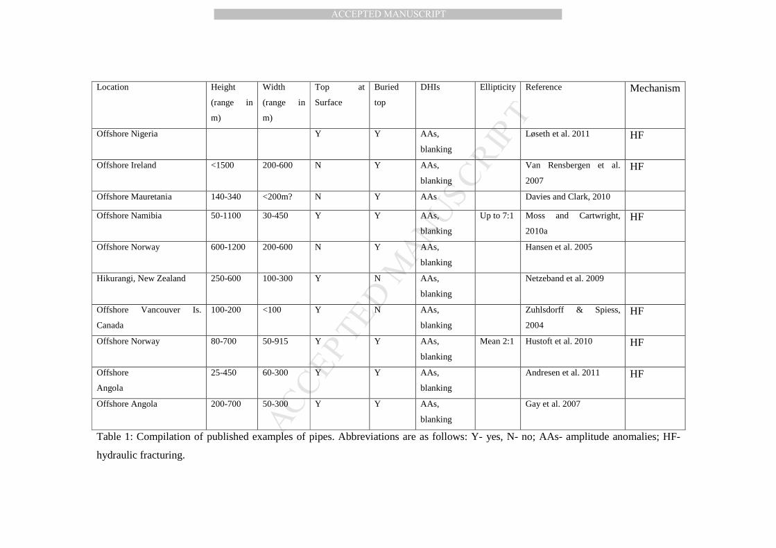
Table 1: Compilation of published examples of pipes. Abbreviations are as follows: Y- yes, N- no; AAs- amplitude anomalies; HF-
hydraulic fracturing.
MANUSCRIP
T
ACCEPTED
ACCEPTED MANUSCRIPT
1
Observed Characteristics Implications for Pipe Genesis
formation in layered, clay-dominated sedimentary basins
low vertical hydraulic conductivity
either single-time formation event or episodic formation
sustained overpressure generation and sporadic release events
decisive vertical orientation gravi-tropic guided formation mechanisms
may exhibit pronounced 10:1 slenderness length-persistent formation mechanism often linked to high-pressure root zones, sometimes related to gas accumulation
fluid driven mechanisms
apparent exclusion distance between neighboring pipes
drained root zone
some pipes form above collapse structures
not fluid driven
possible regional clustering shared formation mechanism alignment may reflect subsurface features
associated to fluid flow conduits or local strains that favor pipe nucleation
termination my take place at pockmarks or mounds on the seafloor or at similar paleo-features within the sediment
vigorous fluid flow and sediment erosion/transport
diffuse termination within the sediment
pipe genesis associated to a deep cavity collapse at the root zone, or a fluid-driven pipe formation where gradually dissipates into a highly permeable layers and can no longer sustain pipe growth
the structure of the host sediment may be preserved -at least in large pipes-
fluid driven mixing is not enough to eradicate the sedimentation structure or formation does not involve high fluid flux
intermediate layers may be missing within pipes
selective fluid-driven removal
2
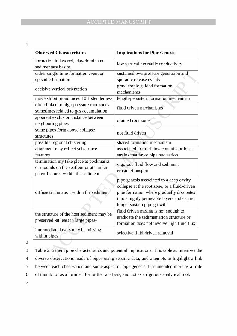
Table 2: Salient pipe characteristics and potential implications. This table summarises the 3
diverse observations made of pipes using seismic data, and attempts to highlight a link 4
between each observation and some aspect of pipe genesis. It is intended more as a ‘rule 5
of thumb’ or as a ‘primer’ for further analysis, and not as a rigorous analytical tool. 6
7
MANUSCRIP
T
ACCEPTED
ACCEPTED MANUSCRIPT
Acknowledgements 8
9
The authors are grateful to Schlumberger for donation of the Geoframe software suite for 10
the seismic interpretation, to colleagues for allowing permission to use their original 11
figures, and to Martino Foschi and David James for discussion. JAC is grateful to Shell 12
for financial support during the completion of this manuscript. 13
14
15
16
17
18
MANUSCRIP
T
ACCEPTED
ACCEPTED MANUSCRIPT
Figure Captions 19
20
Figure 1: Seismic expression of fluid escape pipes. A: Vertical seismic profile through a 21
series of fluid escape pipes from offshore Namibia (from Moss and Cartwright, 2010a). 22
Arrow depicts the base of the pipe, SB- seabed. B: Coherence attribute time slice through 23
a group of pipes showing the typical circular to sub-circular planform, with diameters of 24
100-300m, located offshore Namibia. 25
26
Figure 2: Seismic characteristics of fluid escape pipes (see text for full explanation). A: 27
Seismic profile from offshore Nigeria (from Løseth et al. 2011), showing pipes 28
emanating from a reservoir interval c.1000ms (TWT) below the seabed, terminating in 29
buried or surface pockmarks. B: pipes from offshore Norway, emanating from a gas 30
bearing layer, with convex upwards deformation of host strata and terminating at seafloor 31
pockmarks (from Plaza Faverola et al. 2010a). C: Profile showing several pipes (labelled 32
as chimneys to be consistent with the original figure) all with loss of coherence and 33
subtle convex upwards deformation, from offshore Norway (from Hustoft et al. 2010). D: 34
chair seismic display of two orthogonal seismic profiles and a coherence slice showing 35
chimneys (pipes) from offshore Norway, with variable seafloor expression, but including 36
a large mound (from Hustoft et al. 2010). E: A pipe from offshore Norway, with variable 37
relief exhibited by the convex upwards deformed strata, terminating in a seafloor 38
pockmark (from Hustoft et al. 2010). 39
40
Figure 3: Seismic interpretation of fluid escape pipes is made complicated by different 41
types of seismic artifact. A: A profile from the Faeroe-Shetland Basin, offshore Scotland, 42
showing a zone of attenuation and seismic disruption beneath the root zone of some pipes 43
in a fluid source unit (from Cartwright, 2007). B: Seismic profile from offshore Namibia 44
showing two prominent pipes. The left hand pipe clearly terminates downwards above a 45
coherent reflection (CR), whereas the root of the other pipe is harder to interpret, because 46
of scattering and distortion possibly linked to an amplitude anomaly (AA). 47
48
MANUSCRIP
T
ACCEPTED
ACCEPTED MANUSCRIPT
Figure 4: Seismic image of a large pipe from offshore Norway, showing highly variable 49
seismic expression vertically along the pipe, from a wide root zone, badly affected by 50
artifacts, to a narrower disrupted zone with migration artifacts (MA), upwards to a zone 51
with convex upwards deformation across sharp inflection points (IP) to a shallow region 52
of laterally extensive high amplitude reflections (HARs)(from Hansen et al. 2005). 53
54
Figure 5: Seismic profiles across large diameter pipes from offshore Namibia. A: profile 55
showing a pipe with concave downwards relief and discontinuity of stratal reflections at 56
pipe margins. Note the variable geometry evident at the horizons indicated with circles. 57
B: profile showing thinning of the basal layers within the pipe interior close to the root 58
zone (arrowed). 59
60
Figure 6: Amplitude display of a mapped horizon that is intersected by numerous pipes, 61
offshore Namibia. Some of the pipes are quite sharply delineated by this attribute image 62
(e.g. P), but in others (e.g. Q), the amplitude anomalies associated with the pipe extend 63
laterally outside the pipe margins, blurring the recognition of the margin. 64
65
Figure 7: Seismic profiles showing variation in geometry of pipes. A: profile from 66
offshore Namibia showing an upward tapering conical pipe geometry. B: profile from 67
offshore Mauretania showing a downward tapering conical pipe geometry (from Davies 68
and Clarke, 2010). C: profile from offshore Namibia showing an upwards bifurcating 69
pipe geometry, with pipes A and B linked at a single, high amplitude reflection (see 70
arrows). 71
72
Figure 8: Seismic profiles showing the upward terminations of pipes. A: Upward 73
termination in of a pipe at a large seafloor pockmark (from Andresen et al. 2011). B: 74
Upward termination with gradual reduction in concave relief and local stacking of 75
overlying high amplitude reflections (HARs) (from Moss and Cartwright, 2010a). Note 76
the bottom simulating reflector (BSR) crossing the pipe with no loss of continuity. 77
78
MANUSCRIP
T
ACCEPTED
ACCEPTED MANUSCRIPT
Figure 9: Seismic profile showing a pipe structure that is interpreted to feed a series of 79
near-vertically stacked pockmark craters (P)(from Andresen and Huuse, 2011). 80
81
Figure 10: Cartoon representation of a model for syn-sedimentary, episodic pipe growth. 82
A: step 1, initial formation of pipe at time t0. B: step 2, no pipe growth during deposition 83
up to layer at time t1. C: step 3: new phase of growth of the pipe at time t2 overprints the 84
earlier pipe structure. D: step 4, growth continues as new layers of sediment are 85
deposited to time t3. 86
87
Figure 11: Conceptual model of pipe growth by hydraulic fracturing. A: an initial 88
fracture nucleates and propagates upwards from the interface between the overpressured 89
layer and the overlying seal (inset shows the pressure (P) – depth (Z) plot for this intitial 90
propagation of a hydraulic fracture, at depth Zc and critical fluid pressure in the source, 91
Pr, where this pressure intersects the fracture gradient (F)(see Watts, 1987). H is the 92
hydrostatic gradient, and L the lithostatic gradient. B: As fluid escapes into the seal, a 93
network of small, distributed hydraulic fractures propagates upwards, with some 94
widening of the fractured region. C: The escape of fluid from the overpressured zone is 95
focused into the region of fractures because of enhanced permeability of the fractured 96
seal, and fractures selectively widen and propagate. D: A threshold is reached where 97
fluid flow and fracture network linkage result in increased focusing of flow, higher flow 98
velocity, and possible gas expansion to form the well established cylindrical conduit 99
(pipe) and associated surface expulsion features (see Cartwright et al. 2007for details and 100
original source references) 101
102
Figure 12: Simplified view of a fluidization model for diatreme formation. A: gross 103
geometry of a sedimentary diatreme formed by fluidization. B: Details of the reservoir-104
seal interface, where the pressure gradient drives fluid flow across the boundary and flow 105
in the seal fluidizes the overburden to form the pipe-like conduit. C: Enlargement of the 106
interface to highlight the difficulty in achieving fluidization velocity within the seal when 107
it is largely composed of clay-sized particles. 108
109
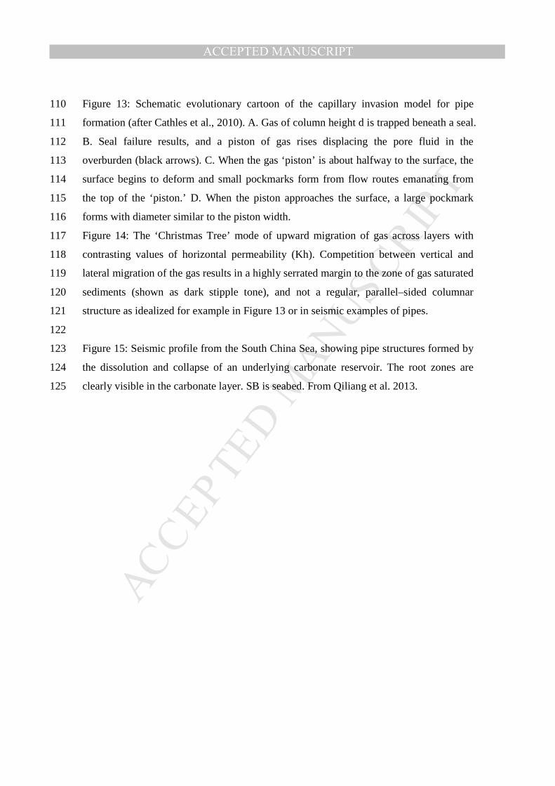
MANUSCRIP
T
ACCEPTED
ACCEPTED MANUSCRIPT
Figure 13: Schematic evolutionary cartoon of the capillary invasion model for pipe 110
formation (after Cathles et al., 2010). A. Gas of column height d is trapped beneath a seal. 111
B. Seal failure results, and a piston of gas rises displacing the pore fluid in the 112
overburden (black arrows). C. When the gas ‘piston’ is about halfway to the surface, the 113
surface begins to deform and small pockmarks form from flow routes emanating from 114
the top of the ‘piston.’ D. When the piston approaches the surface, a large pockmark 115
forms with diameter similar to the piston width. 116
Figure 14: The ‘Christmas Tree’ mode of upward migration of gas across layers with 117
contrasting values of horizontal permeability (Kh). Competition between vertical and 118
lateral migration of the gas results in a highly serrated margin to the zone of gas saturated 119
sediments (shown as dark stipple tone), and not a regular, parallel–sided columnar 120
structure as idealized for example in Figure 13 or in seismic examples of pipes. 121
122
Figure 15: Seismic profile from the South China Sea, showing pipe structures formed by 123
the dissolution and collapse of an underlying carbonate reservoir. The root zones are 124
clearly visible in the carbonate layer. SB is seabed. From Qiliang et al. 2013. 125
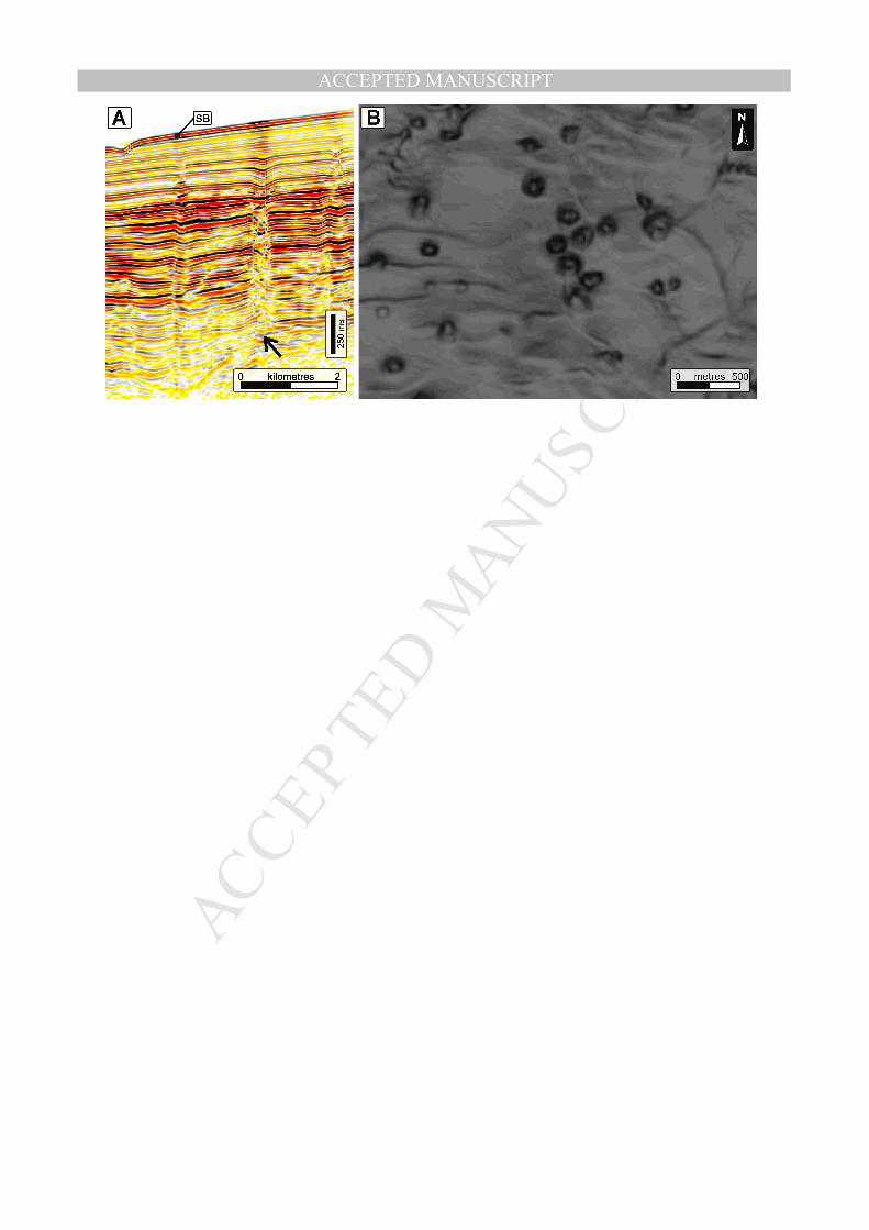
MANUSCRIP
T
ACCEPTED
ACCEPTED MANUSCRIPT
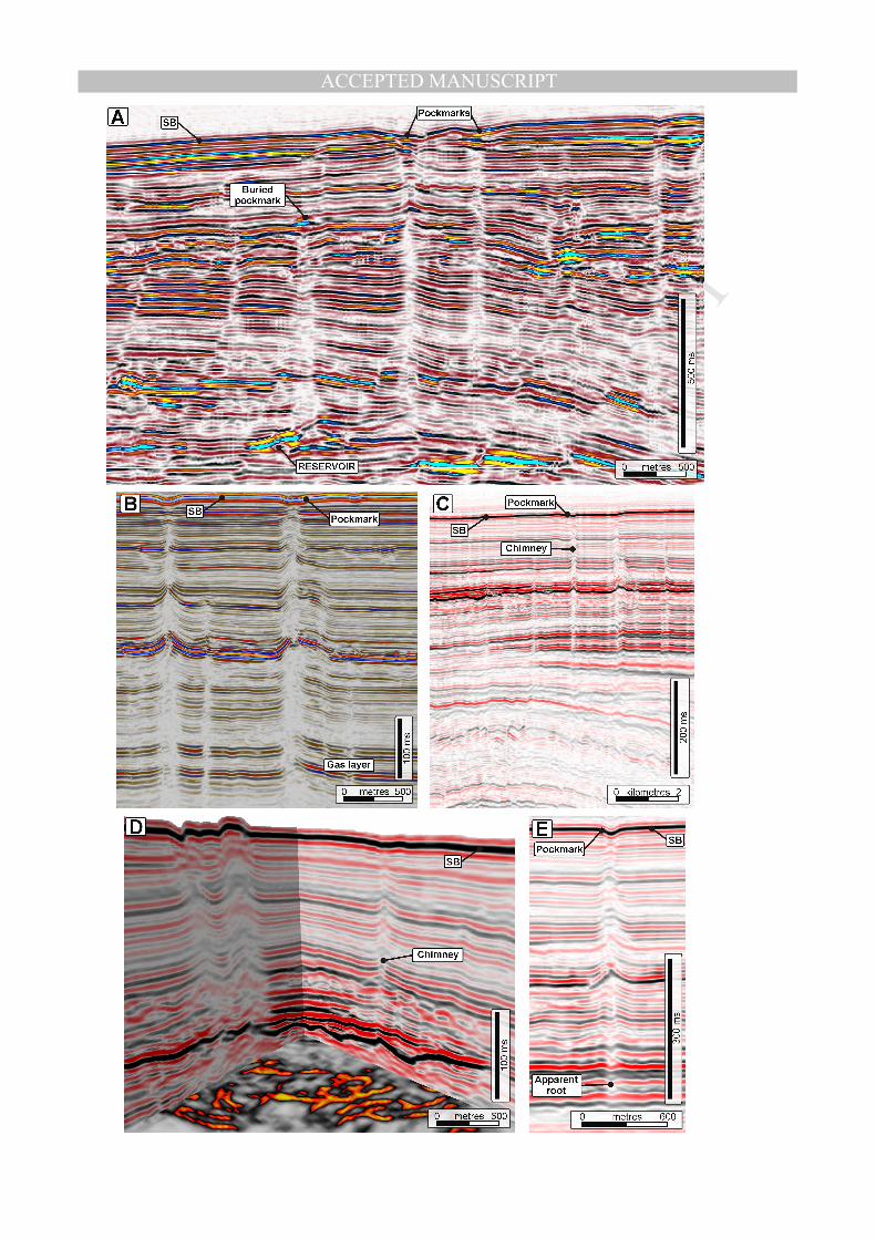
MANUSCRIP
T
ACCEPTED
ACCEPTED MANUSCRIPT
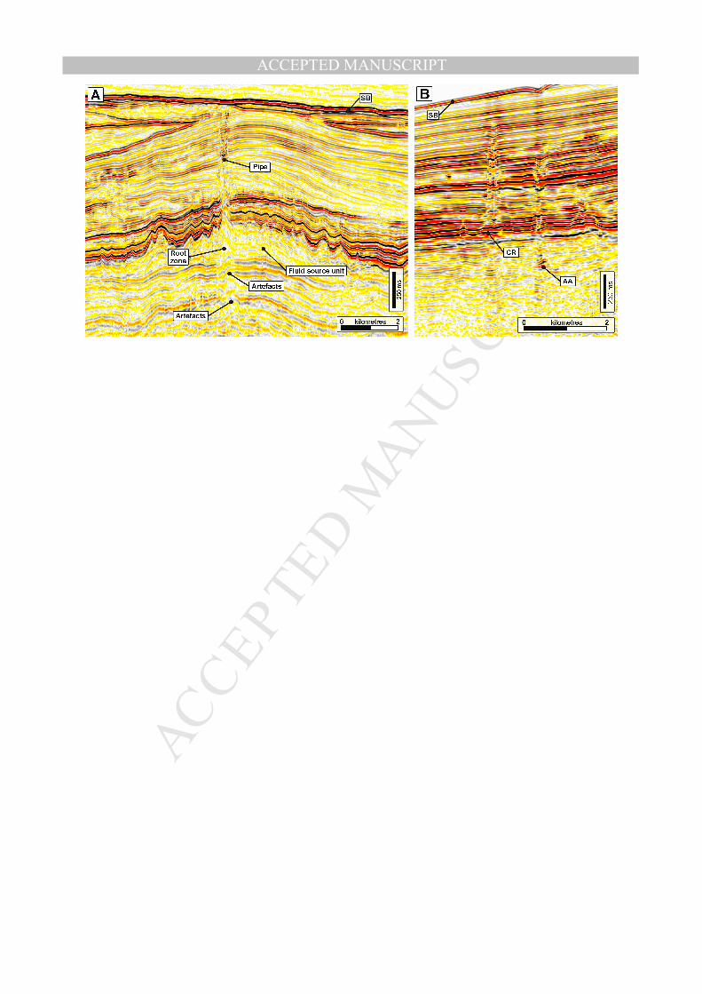
MANUSCRIP
T
ACCEPTED
ACCEPTED MANUSCRIPT
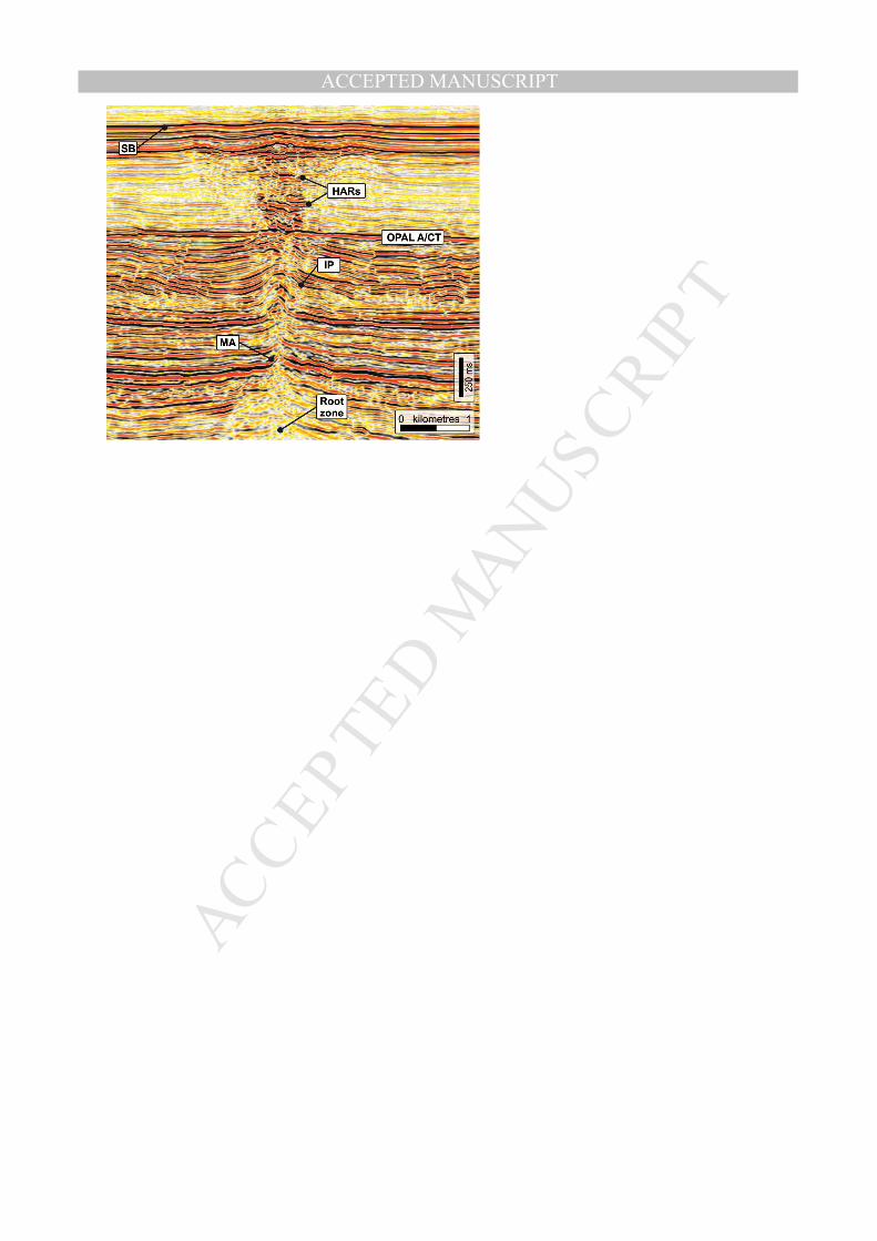
MANUSCRIP
T
ACCEPTED
ACCEPTED MANUSCRIPT
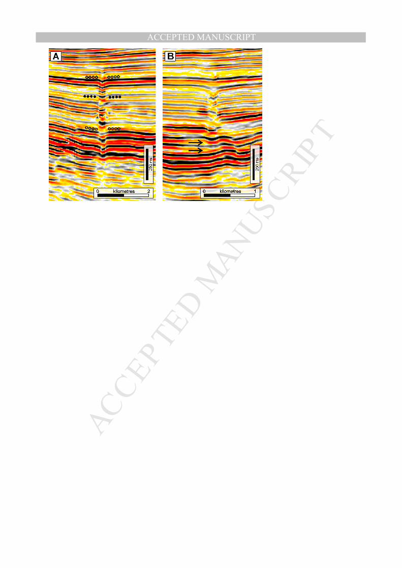
MANUSCRIP
T
ACCEPTED
ACCEPTED MANUSCRIPT

MANUSCRIP
T
ACCEPTED
ACCEPTED MANUSCRIPT
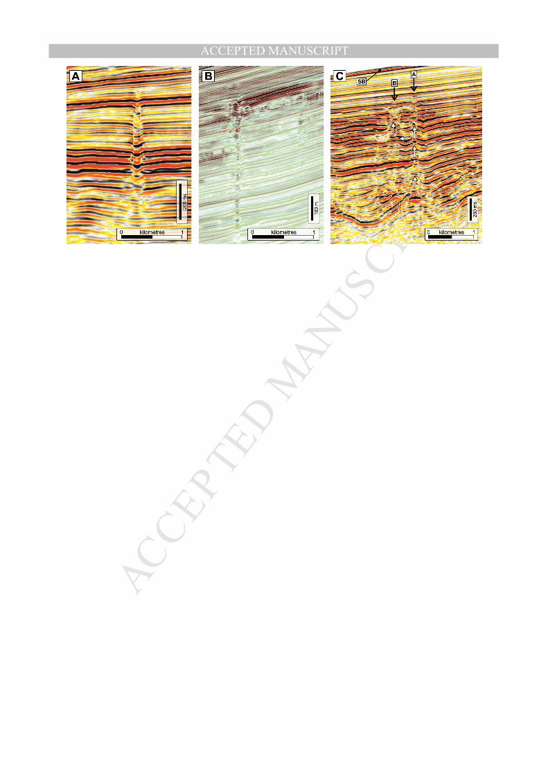
MANUSCRIP
T
ACCEPTED
ACCEPTED MANUSCRIPT
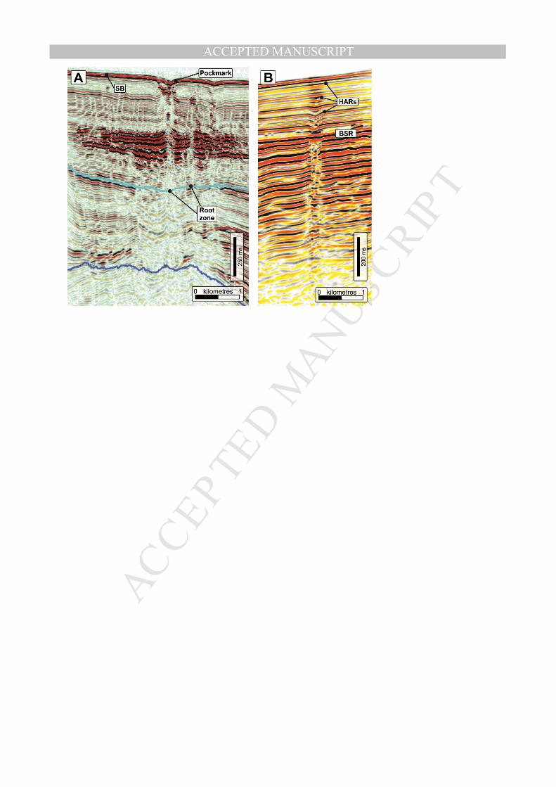
MANUSCRIP
T
ACCEPTED
ACCEPTED MANUSCRIPT
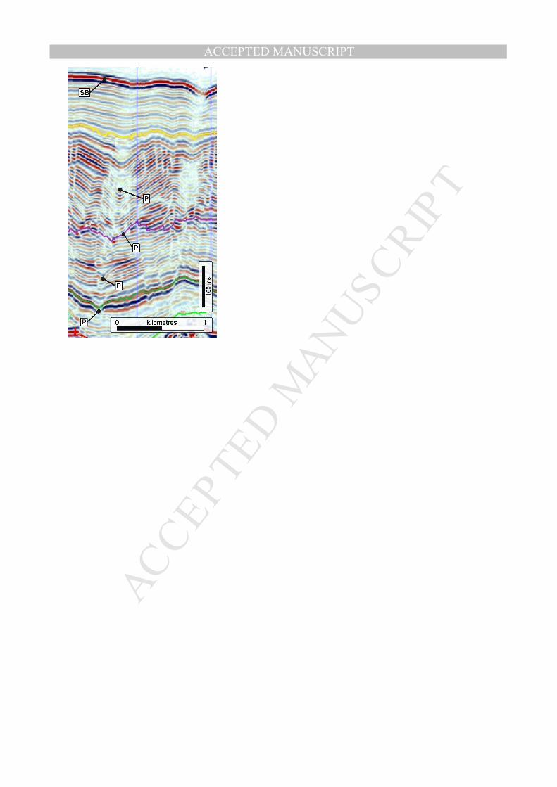
MANUSCRIP
T
ACCEPTED
ACCEPTED MANUSCRIPT
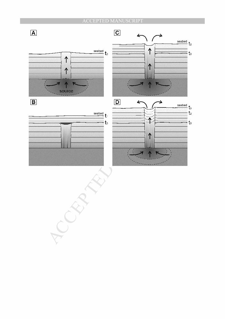
MANUSCRIP
T
ACCEPTED
ACCEPTED MANUSCRIPT
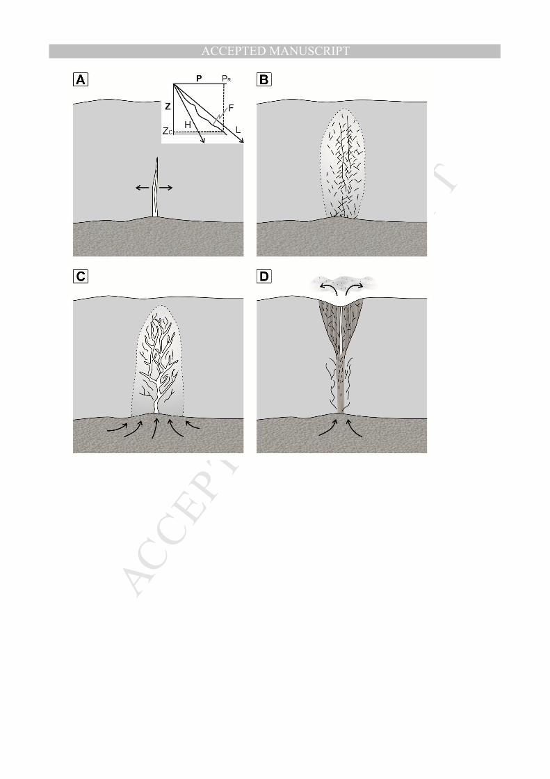
MANUSCRIP
T
ACCEPTED
ACCEPTED MANUSCRIPT
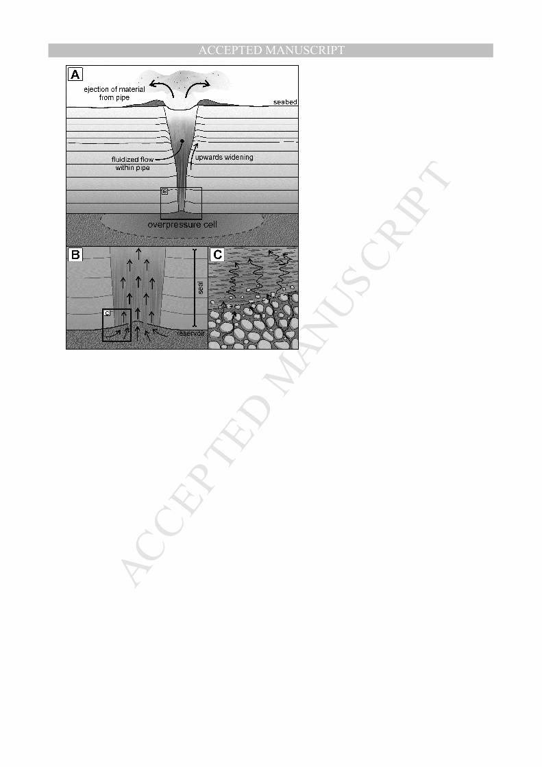
MANUSCRIP
T
ACCEPTED
ACCEPTED MANUSCRIPT
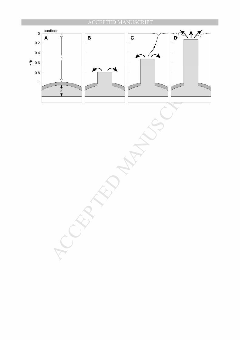
MANUSCRIP
T
ACCEPTED
ACCEPTED MANUSCRIPT
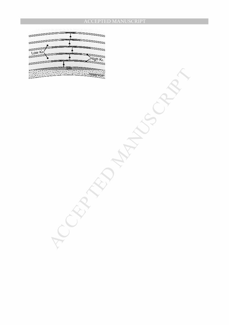
MANUSCRIP
T
ACCEPTED
ACCEPTED MANUSCRIPT
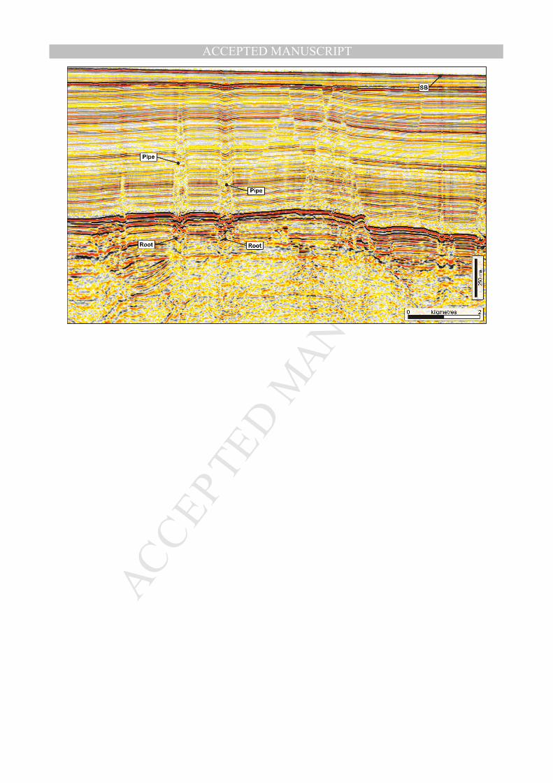
MANUSCRIP
T
ACCEPTED
ACCEPTED MANUSCRIPT
MANUSCRIP
T
ACCEPTED
ACCEPTED MANUSCRIPT
Highlights for JMPG-D-14-00298 Cartwright and Santamarina
• Fluid escape pipes are formed by focused fluid expulsion, found in many petroliferous basins
• Characterized on seismic data by columnar zones of reduced reflection continuity
• Pipes are tens to thousands of metres tall, and tens to hundreds of metres wide
• Pipes are frequently associated with signs of free gas migration such as amplitude anomalies or cemented zones
• Genetic mechanisms include hydraulic fracturing, erosional fluidisation, capillary invasion, and volume collapse