Embed Size (px)
Citation preview
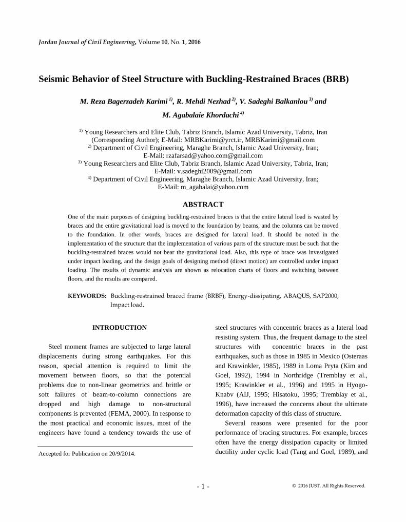
Jordan Journal of Civil Engineering, Volume 10, No. 1, 2016
- 1 - © 2016 JUST. All Rights Reserved.
Seismic Behavior of Steel Structure with Buckling-Restrained Braces (BRB)
M. Reza Bagerzadeh Karimi 1), R. Mehdi Nezhad 2), V. Sadeghi Balkanlou 3) and
M. Agabalaie Khordachi 4)
1) Young Researchers and Elite Club, Tabriz Branch, Islamic Azad University, Tabriz, Iran
(Corresponding Author); E-Mail: [email protected], [email protected] 2) Department of Civil Engineering, Maraghe Branch, Islamic Azad University, Iran;
E-Mail: [email protected]@gmail.com 3) Young Researchers and Elite Club, Tabriz Branch, Islamic Azad University, Tabriz, Iran;
E-Mail: [email protected]
4) Department of Civil Engineering, Maraghe Branch, Islamic Azad University, Iran;
E-Mail: [email protected]
ABSTRACT
One of the main purposes of designing buckling-restrained braces is that the entire lateral load is wasted by
braces and the entire gravitational load is moved to the foundation by beams, and the columns can be moved
to the foundation. In other words, braces are designed for lateral load. It should be noted in the
implementation of the structure that the implementation of various parts of the structure must be such that the
buckling-restrained braces would not bear the gravitational load. Also, this type of brace was investigated
under impact loading, and the design goals of designing method (direct motion) are controlled under impact
loading. The results of dynamic analysis are shown as relocation charts of floors and switching between
floors, and the results are compared.
KEYWORDS: Buckling-restrained braced frame (BRBF), Energy-dissipating, ABAQUS, SAP2000,
Impact load.
INTRODUCTION
Steel moment frames are subjected to large lateral
displacements during strong earthquakes. For this
reason, special attention is required to limit the
movement between floors, so that the potential
problems due to non-linear geometrics and brittle or
soft failures of beam-to-column connections are
dropped and high damage to non-structural
components is prevented (FEMA, 2000). In response to
the most practical and economic issues, most of the
engineers have found a tendency towards the use of
steel structures with concentric braces as a lateral load
resisting system. Thus, the frequent damage to the steel
structures with concentric braces in the past
earthquakes, such as those in 1985 in Mexico (Osteraas
and Krawinkler, 1985), 1989 in Loma Pryta (Kim and
Goel, 1992), 1994 in Northridge (Tremblay et al.,
1995; Krawinkler et al., 1996) and 1995 in Hyogo-
Knabv (AIJ, 1995; Hisatoku, 1995; Tremblay et al.,
1996), have increased the concerns about the ultimate
deformation capacity of this class of structure.
Several reasons were presented for the poor
performance of bracing structures. For example, braces
often have the energy dissipation capacity or limited
ductility under cyclic load (Tang and Goel, 1989), and Accepted for Publication on 20/9/2014.
Seismic Behavior of … M. Reza Bagerzadeh Karimi, R. Mehdi Nezhad, V. Sadeghi Balkanlou and M. Agabalaie Khordachi
- 2 -
most connections are subjected to vulnerable behavior.
Hysteresis behavior of the braces is quite complicated
and shows asymmetric characteristics of stretch and
strain and a great reduction in the resistance, while
there is uniform loading at the pressure or intermittent
load in the inelastic range. This complex behavior can
lead to large differences between the distribution of
internal forces and predicted deformations using
conventional design methods based on very realistic
elastic behavior models and non-linear analysis
processes (Jain and Goel, 1979; Khatib and Mahin,
1987). Consequences of such behavior differences are
twofold:
The selected braces for some floors are often much
stronger than the required extent, while the braces of
other floors have capacities very close to the design
goals, and the distribution of design forces in the
columns and beams is often different from the expected
rate of real earthquakes. These differences lead to
earthquake damage on several poor floors. Some
damages occur a little more than the ductility capacities
of usual braces and their connections. It should be
noted that the lateral buckling of conventional braces
may cause great damage to the adjacent non-structural
components. Seismic design requirements for bracing
structures have considerably changed during the 1990s
and the concept of concentric bracing structures has
been proposed (AISC, 1997; ICBO, 1997).
Considerable studies have begun to increase the
performance of bracing structures by providing a new
structure or the use of special braces including (Ku,
1999) the braces using the flow of metal (Kamura et
al., 2000; Ohi et al., 2001), high-performance materials
(Aiken et al., 1992), friction and viscous damper
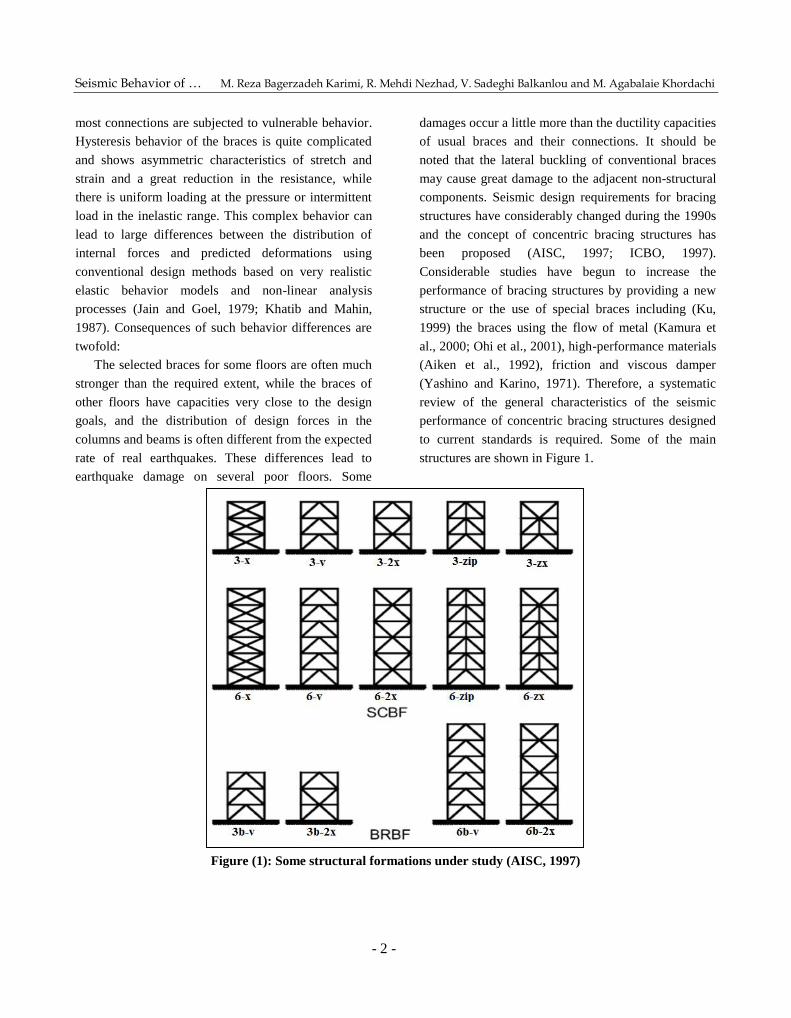
(Yashino and Karino, 1971). Therefore, a systematic
review of the general characteristics of the seismic
performance of concentric bracing structures designed
to current standards is required. Some of the main
structures are shown in Figure 1.
Figure (1): Some structural formations under study (AISC, 1997)
Jordan Journal of Civil Engineering, Volume 10, No. 1, 2016
- 3 -
Some studies have been conducted on BRB by
Yashino and Karino (1971).They performed some
alternative experiments on two samples called “shear
wall or bracer”, which consisted of a flat metal plate
covered with reinforced concrete. Wakabayashi et al.
(Xie, 2005) made a bracing system consisting of a flat
metal plate with a layer of reinforced concrete by
reducing the friction between them.
Another experiment was conducted by Kimureat on
metal bracer covered with mortar inside the metal tube.
Tube filled with mortar showed its effectiveness
against core buckling. In a subsequent study, 4 samples
with real sizes were tested under seismic load. It was
concluded that if the ratio between the outer sheath of
elastic buckling strength and yield strength of the
bracer core is larger than 1/9, no buckling would occur
at the bracer core and the prototype shows good
behavior of the hysteresis cycle. Iwata et al. (2000)
investigated the periodic performance of some anti-
buckling braces available in Japan. Three large braces
were tested at Berkely University to help design and
build a structure with BRB.
Black et al. (2002) performed a different analysis
on large earthquakes and the elastic torsional buckling
of the core to investigate the stability of the inner core.
Chen found that the use of low-resistance metal makes
a low flexural deformation at the bracer leading to
greater flexibility. In a study conducted by Uang and
Nakashima, the advantage of using BRB in dual system
for reducing permanent deformation was investigated
(Uang and Nakashima, 2004).
Min, Tsai and Hsiao (2005) studied the effect of
friction reducers on the periodic response of braces.
Sabelli increased the seismic absorption of frames by
coating the bracing system.
Kim and Seo (2004) and Kim and Choi (2004)
presented a process for BRBF seismic design based on
energy dissipation and a direct displacement design
process. Their studies aimed to investigate the design
of steel structures with buckling-restrained braces as
well as to investigate the behavior of the braces. The
behavior of these braces was investigated under impact
load, while the design goals of the designing method
(direct motion) under impact load were controlled.
Results of dynamic analysis are shown as the
relocation charts of floors and the switching between
floors, and the results are compared. To ensure
modeling and determining of error rate, modeling was
repeated with SAP2000 software, which is explained
below.
MODELING AND ANALYSIS
To check the accuracy of modeling and compare
the results with the goals of the design, a dynamic
analysis was performed using finite element software
of ABAQUS (Sommerville et al., 1997). A steel
structure frame with three floors and a mouth buckled
using buckling-restrained braces went through a
dynamic analysis.
Since the design of this type of structure; namely
steel frames with buckling-restrained braces, is based
on the principle that the beams and columns remain
perfectly elastic due to the earthquake and the seismic
load is wasted by braces, thus the structure design is
limited only to braces design, and the beams and
columns designed for gravitational load and component
load of braces are identical in all samples. The only
difference between the four different models is the size
of braces and other structural elements, and the
characteristics are the same in all cases.
Structural Modeling
Frame Elements
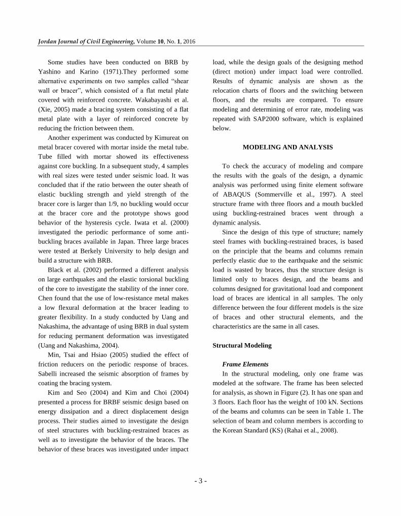
In the structural modeling, only one frame was
modeled at the software. The frame has been selected
for analysis, as shown in Figure (2). It has one span and
3 floors. Each floor has the weight of 100 kN. Sections
of the beams and columns can be seen in Table 1. The
selection of beam and column members is according to
the Korean Standard (KS) (Rahai et al., 2008).
Seismic Behavior of … M. Reza Bagerzadeh Karimi, R. Mehdi Nezhad, V. Sadeghi Balkanlou and M. Agabalaie Khordachi
- 4 -
Figure (2): 3-floor frame and a mouth
Table 1. Sections of beams and columns (mm)
Storey Columns Beams
1-2 H 250 x 250 x 9 x 14 H 400 x 200 x 8 x 13
3 H 200 x 200 x 8 x 12
Cross-section of buckling resistant braces,
considering the target displacements: 1% (case A),
1.5% (case B), 2% (case C) and 2.5% (case D) height
of the roof level, were determined as shown in Table 2.
Table 2. Cross-section of braces (cm2)
Storey Case A Case B Case C Case D
1 2.18 1.09 0.97 0.89
2 1.82 0.91 0.81 0.74
3 1.09 0.54 0.49 0.44
As seen in Table 2, with increasing displacement of
the target, the cross-section of braces is reduced.
According to Figure (3), it can be seen that with
increasing target displacement (Um), Sa value is
reduced. Thus, reducing Sa according to equation (1)
has a direct relationship with base shear (Fy). In other
words, reducing the Sa value reduces the base shear
value.
Fy = M × Sa (1)
Figure (3): Response spectrum of displacement-
acceleration (ADRS)
Thus, by reducing the amount of base shear
according to the following equation, the amount of
brace cross-section will decrease.
A =Fy
cosθσy. (2)
This problem can be explained as the same about
the reduction of brace cross-section along the structure
height. If we assume that the target displacement of
structure is equal to the sum of the target structure
displacement of the floors level, thus, the target
displacement of the floors level increases by increasing
the height of the floors level, resulting in the reduced
cross-section of brace for that floor.
As we shall see, the reduced cross-section of brace
in higher floors will have some advantages, among
which the following points may be mentioned:
1. Preventing the formation of poor floor.
2. Smoothing the displacement between floors.
3. Uniform energy dissipation along the structural
height.
However, all the issues above are among the goals
of metal frames design with buckling-restrained braces.
Material Characteristics of the Elements
Since the units of N and mm are used for modeling,
thus the modulus of elasticity of steel used in beams and
columns was considered as E=210000 N/mm2. Yield
stress and failure stress were respectively considered as
240 and 420 N/mm2. Poisson's ratio of 0.3 was used in the
modeling. As previously mentioned, the steel used in
Jordan Journal of Civil Engineering, Volume 10, No. 1, 2016
- 5 -
buckling-restrained braces is low-strength steel; namely
steel with yield stress of 100 MPa.
Creating Elements
Columns
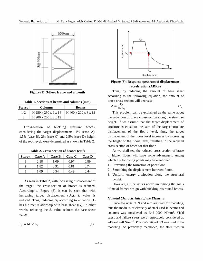
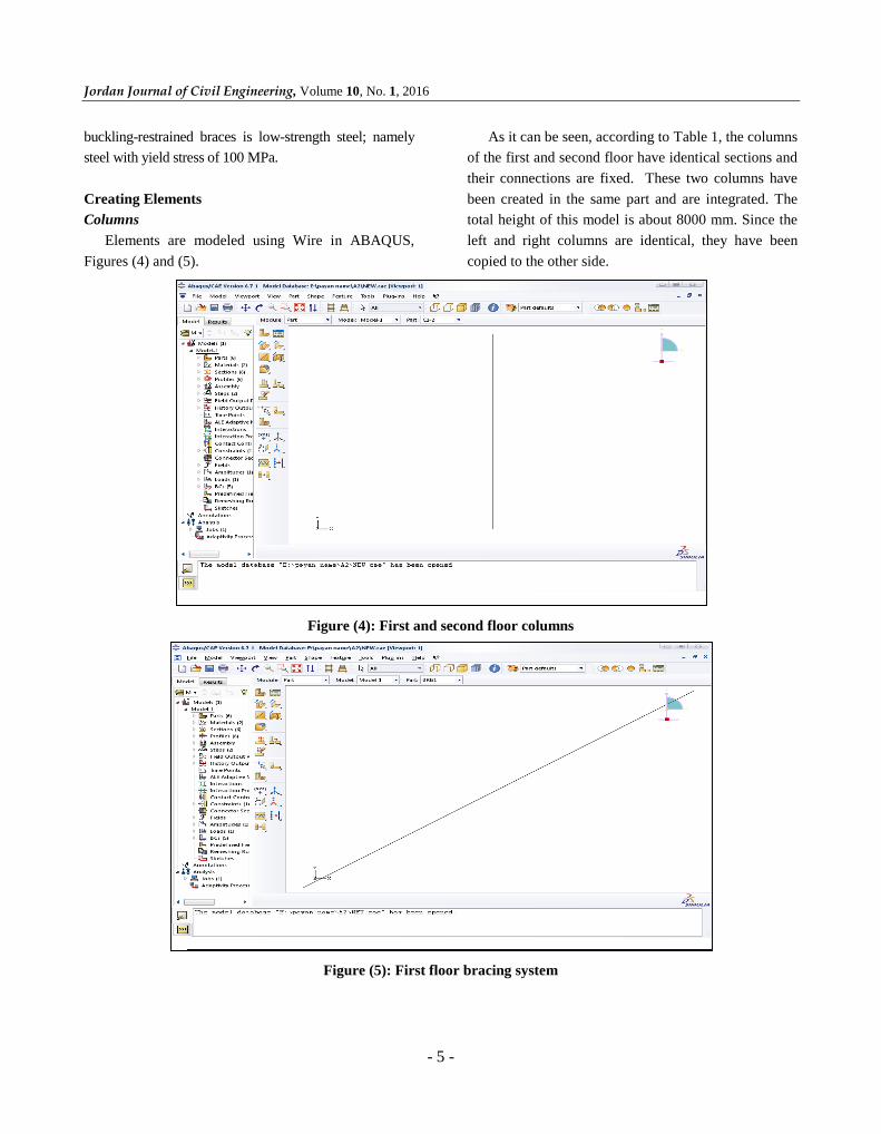
Elements are modeled using Wire in ABAQUS,
Figures (4) and (5).
As it can be seen, according to Table 1, the columns
of the first and second floor have identical sections and
their connections are fixed. These two columns have
been created in the same part and are integrated. The
total height of this model is about 8000 mm. Since the
left and right columns are identical, they have been
copied to the other side.
Figure (4): First and second floor columns
Figure (5): First floor bracing system
Seismic Behavior of … M. Reza Bagerzadeh Karimi, R. Mehdi Nezhad, V. Sadeghi Balkanlou and M. Agabalaie Khordachi
- 6 -
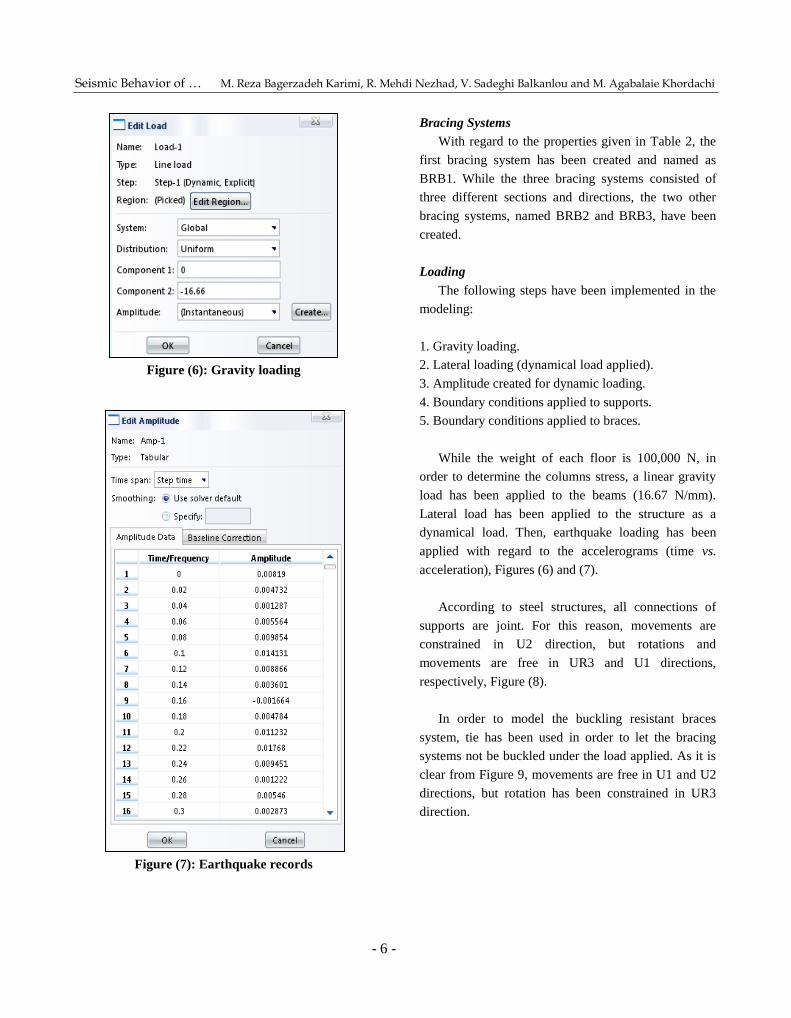
Figure (6): Gravity loading
Figure (7): Earthquake records
Bracing Systems
With regard to the properties given in Table 2, the
first bracing system has been created and named as
BRB1. While the three bracing systems consisted of
three different sections and directions, the two other
bracing systems, named BRB2 and BRB3, have been
created.
Loading
The following steps have been implemented in the
modeling:
1. Gravity loading.
2. Lateral loading (dynamical load applied).
3. Amplitude created for dynamic loading.
4. Boundary conditions applied to supports.
5. Boundary conditions applied to braces.
While the weight of each floor is 100,000 N, in
order to determine the columns stress, a linear gravity
load has been applied to the beams (16.67 N/mm).
Lateral load has been applied to the structure as a
dynamical load. Then, earthquake loading has been
applied with regard to the accelerograms (time vs.
acceleration), Figures (6) and (7).
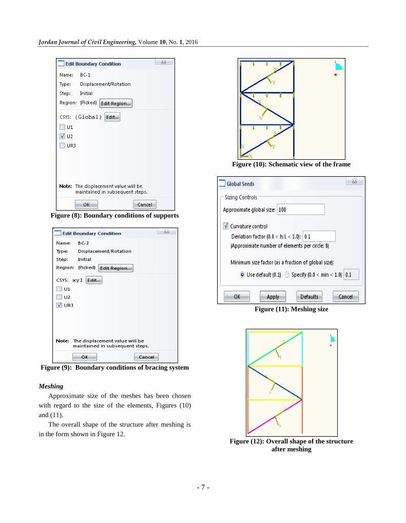
According to steel structures, all connections of
supports are joint. For this reason, movements are
constrained in U2 direction, but rotations and
movements are free in UR3 and U1 directions,
respectively, Figure (8).
In order to model the buckling resistant braces
system, tie has been used in order to let the bracing
systems not be buckled under the load applied. As it is
clear from Figure 9, movements are free in U1 and U2
directions, but rotation has been constrained in UR3
direction.
Jordan Journal of Civil Engineering, Volume 10, No. 1, 2016
- 7 -
Figure (8): Boundary conditions of supports
Figure (9): Boundary conditions of bracing system
Meshing
Approximate size of the meshes has been chosen
with regard to the size of the elements, Figures (10)
and (11).
The overall shape of the structure after meshing is
in the form shown in Figure 12.
Figure (10): Schematic view of the frame
Figure (11): Meshing size
Figure (12): Overall shape of the structure
after meshing
Seismic Behavior of … M. Reza Bagerzadeh Karimi, R. Mehdi Nezhad, V. Sadeghi Balkanlou and M. Agabalaie Khordachi
- 8 -
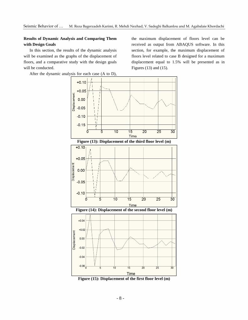
Results of Dynamic Analysis and Comparing Them
with Design Goals
In this section, the results of the dynamic analysis
will be examined as the graphs of the displacement of
floors, and a comparative study with the design goals
will be conducted.
After the dynamic analysis for each case (A to D),
the maximum displacement of floors level can be
received as output from ABAQUS software. In this
section, for example, the maximum displacement of
floors level related to case B designed for a maximum
displacement equal to 1.5% will be presented as in
Figures (13) and (15).
Figure (13): Displacement of the third floor level (m)
Figure (14): Displacement of the second floor level (m)
Figure (15): Displacement of the first floor level (m)
Jordan Journal of Civil Engineering, Volume 10, No. 1, 2016
- 9 -
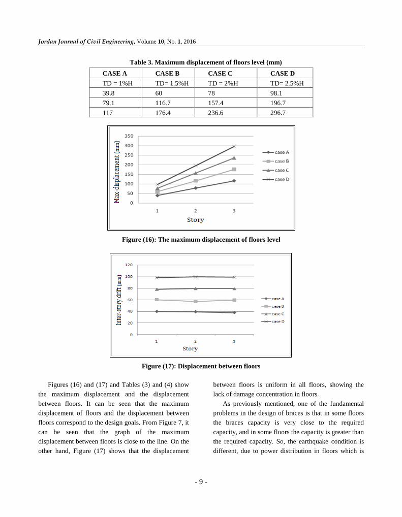
Table 3. Maximum displacement of floors level (mm)
CASE D CASE C CASE B CASE A
TD= 2.5%H TD = 2%H TD= 1.5%H TD = 1%H
98.1 78 60 39.8
196.7 157.4 116.7 79.1
296.7 236.6 176.4 117
Figure (16): The maximum displacement of floors level
Figure (17): Displacement between floors
Figures (16) and (17) and Tables (3) and (4) show
the maximum displacement and the displacement
between floors. It can be seen that the maximum
displacement of floors and the displacement between
floors correspond to the design goals. From Figure 7, it
can be seen that the graph of the maximum
displacement between floors is close to the line. On the
other hand, Figure (17) shows that the displacement
between floors is uniform in all floors, showing the
lack of damage concentration in floors.
As previously mentioned, one of the fundamental
problems in the design of braces is that in some floors
the braces capacity is very close to the required
capacity, and in some floors the capacity is greater than
the required capacity. So, the earthquake condition is
different, due to power distribution in floors which is
Seismic Behavior of … M. Reza Bagerzadeh Karimi, R. Mehdi Nezhad, V. Sadeghi Balkanlou and M. Agabalaie Khordachi
- 10 -
different from power distribution considered in the
design; thus, due to the focus of damage on the poor
floor, the entire structure will be damaged. In the
design method, the direct displacement of the brace
cross-section is determined so that the problem is
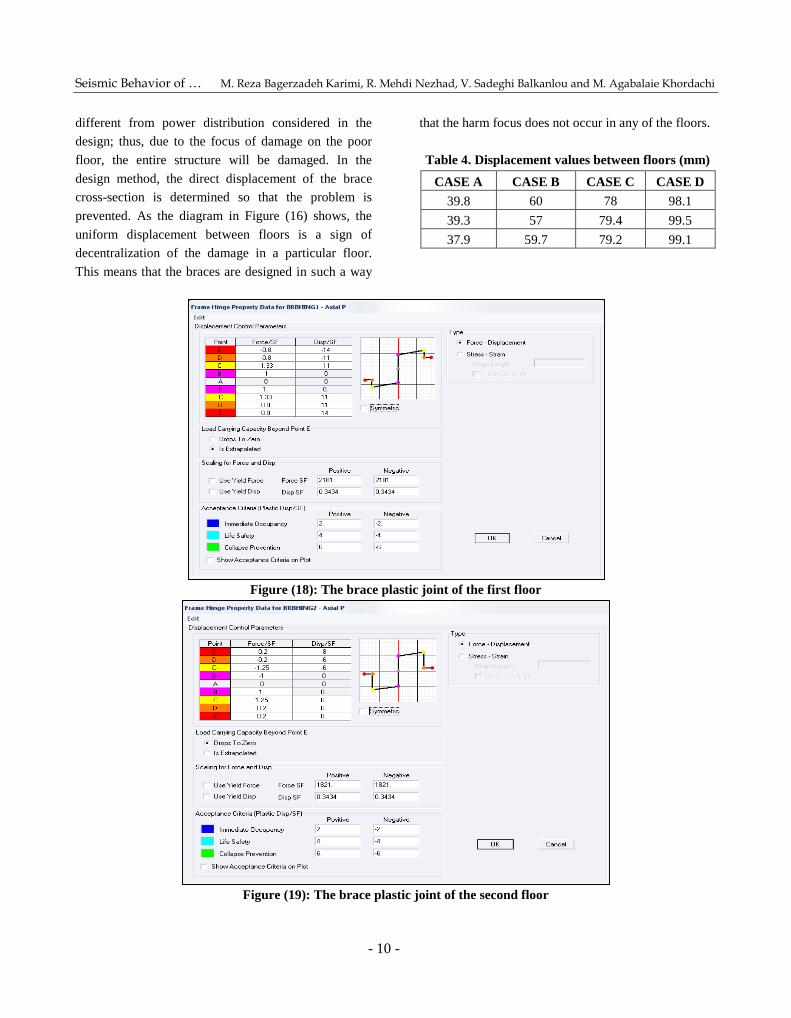
prevented. As the diagram in Figure (16) shows, the
uniform displacement between floors is a sign of
decentralization of the damage in a particular floor.
This means that the braces are designed in such a way
that the harm focus does not occur in any of the floors.
Table 4. Displacement values between floors (mm)
CASE D CASE C CASE B CASE A
98.1 78 60 39.8
99.5 79.4 57 39.3
99.1 79.2 59.7 37.9
Figure (18): The brace plastic joint of the first floor
Figure (19): The brace plastic joint of the second floor
Jordan Journal of Civil Engineering, Volume 10, No. 1, 2016
- 11 -
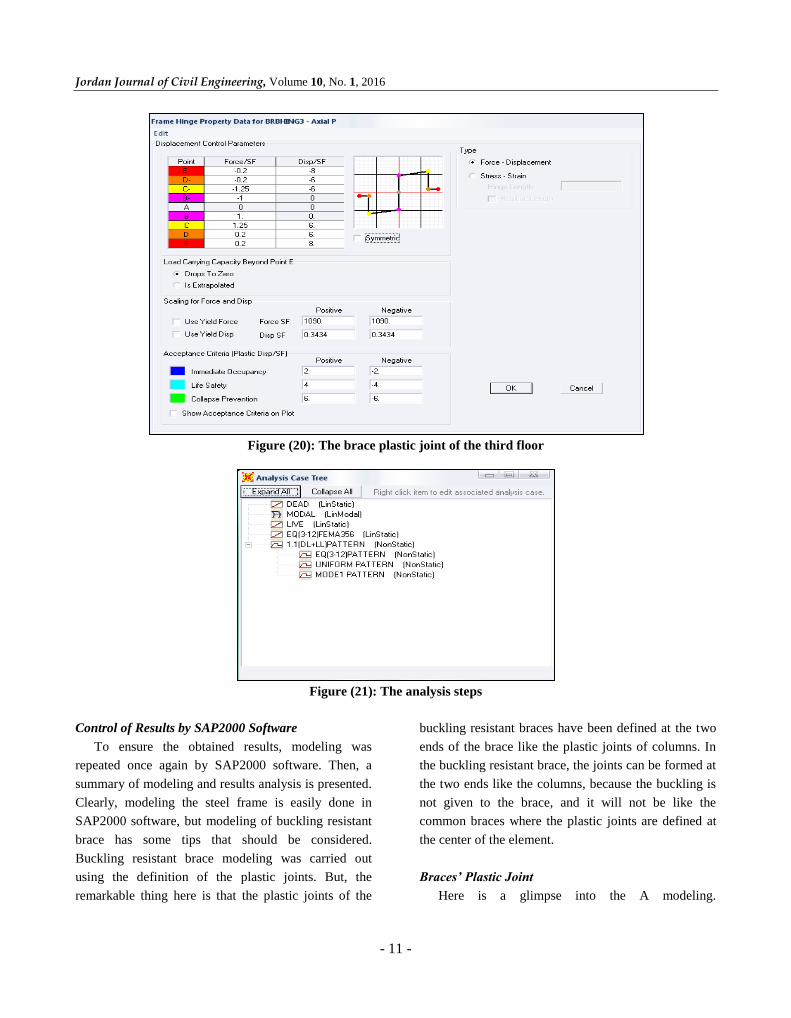
Figure (20): The brace plastic joint of the third floor
Figure (21): The analysis steps
Control of Results by SAP2000 Software
To ensure the obtained results, modeling was
repeated once again by SAP2000 software. Then, a
summary of modeling and results analysis is presented.
Clearly, modeling the steel frame is easily done in
SAP2000 software, but modeling of buckling resistant
brace has some tips that should be considered.
Buckling resistant brace modeling was carried out
using the definition of the plastic joints. But, the
remarkable thing here is that the plastic joints of the
buckling resistant braces have been defined at the two
ends of the brace like the plastic joints of columns. In
the buckling resistant brace, the joints can be formed at
the two ends like the columns, because the buckling is
not given to the brace, and it will not be like the
common braces where the plastic joints are defined at
the center of the element.
Braces’ Plastic Joint
Here is a glimpse into the A modeling.
Seismic Behavior of … M. Reza Bagerzadeh Karimi, R. Mehdi Nezhad, V. Sadeghi Balkanlou and M. Agabalaie Khordachi
- 12 -
Characteristics of braces’ plastic joint at the ends of the
brace were entered according to Figures (18) to (20).
As can be seen, the coefficients of load and
displacement are the same for both pull and push
modes. In the Scaling for force and Disp section, the
entered coefficients according to the amount of cross-
section were as same as the stretch and pressure modes.
Values of Scaling for force and Disp were entered
according to the cross-section of brace and the yield
stress of the brace. For example, for case A, the cross-
section of brace is 2.18 cm2 on the first floor and the
yield stress of brace is 1,000 kg/cm2.
Scaling for force and Disp = 2.18 X 1000 = 218 kgf.
SAP2000 Analysis Results and Comparison with
Design Goals
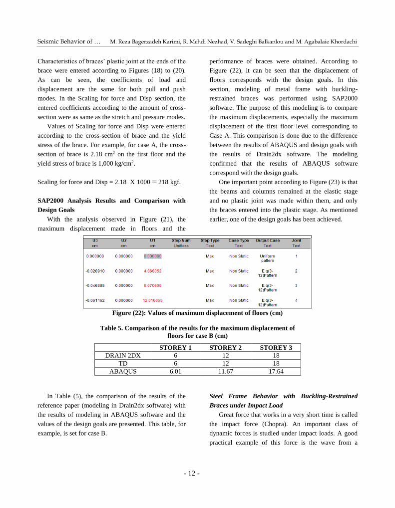
With the analysis observed in Figure (21), the
maximum displacement made in floors and the
performance of braces were obtained. According to
Figure (22), it can be seen that the displacement of
floors corresponds with the design goals. In this
section, modeling of metal frame with buckling-
restrained braces was performed using SAP2000
software. The purpose of this modeling is to compare
the maximum displacements, especially the maximum
displacement of the first floor level corresponding to
Case A. This comparison is done due to the difference
between the results of ABAQUS and design goals with
the results of Drain2dx software. The modeling
confirmed that the results of ABAQUS software
correspond with the design goals.
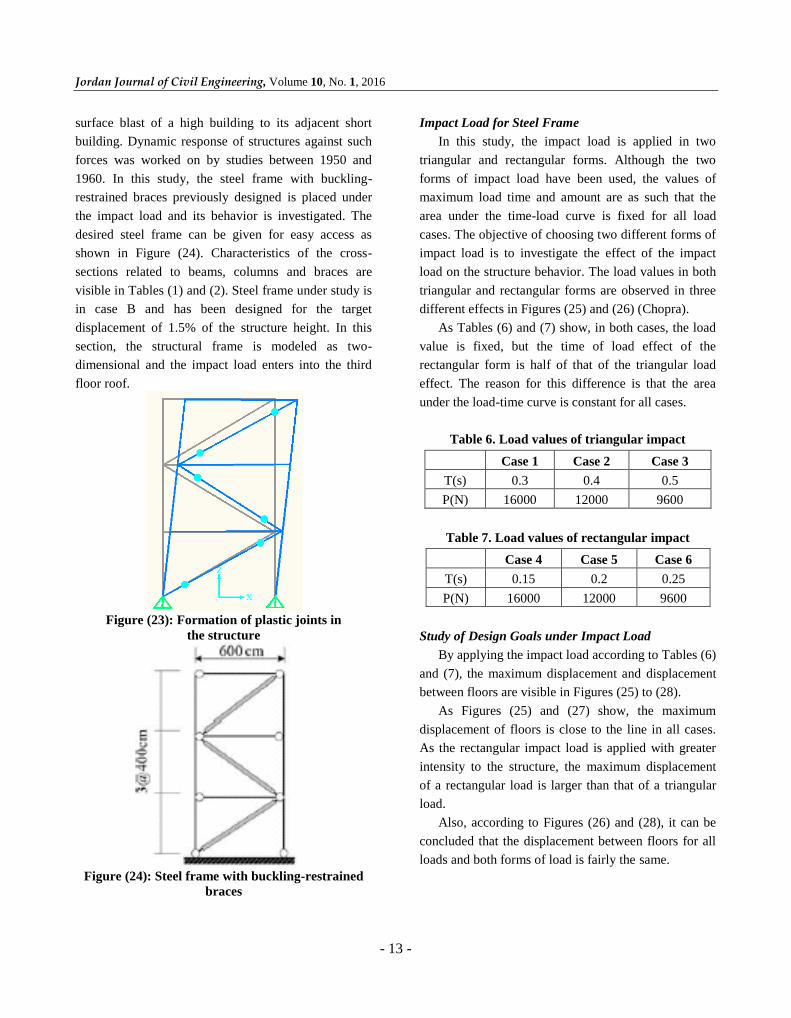
One important point according to Figure (23) is that
the beams and columns remained at the elastic stage
and no plastic joint was made within them, and only
the braces entered into the plastic stage. As mentioned
earlier, one of the design goals has been achieved.
Figure (22): Values of maximum displacement of floors (cm)
Table 5. Comparison of the results for the maximum displacement of
floors for case B (cm)
STOREY 3 STOREY 2 STOREY 1
18 12 6 DRAIN 2DX
18 12 6 TD 17.64 11.67 6.01 ABAQUS
In Table (5), the comparison of the results of the
reference paper (modeling in Drain2dx software) with
the results of modeling in ABAQUS software and the
values of the design goals are presented. This table, for
example, is set for case B.
Steel Frame Behavior with Buckling-Restrained
Braces under Impact Load
Great force that works in a very short time is called
the impact force (Chopra). An important class of
dynamic forces is studied under impact loads. A good
practical example of this force is the wave from a
Jordan Journal of Civil Engineering, Volume 10, No. 1, 2016
- 13 -
surface blast of a high building to its adjacent short
building. Dynamic response of structures against such
forces was worked on by studies between 1950 and
1960. In this study, the steel frame with buckling-
restrained braces previously designed is placed under
the impact load and its behavior is investigated. The
desired steel frame can be given for easy access as
shown in Figure (24). Characteristics of the cross-
sections related to beams, columns and braces are
visible in Tables (1) and (2). Steel frame under study is
in case B and has been designed for the target
displacement of 1.5% of the structure height. In this
section, the structural frame is modeled as two-
dimensional and the impact load enters into the third
floor roof.
Figure (23): Formation of plastic joints in
the structure
Figure (24): Steel frame with buckling-restrained
braces
Impact Load for Steel Frame
In this study, the impact load is applied in two
triangular and rectangular forms. Although the two
forms of impact load have been used, the values of
maximum load time and amount are as such that the
area under the time-load curve is fixed for all load
cases. The objective of choosing two different forms of
impact load is to investigate the effect of the impact
load on the structure behavior. The load values in both
triangular and rectangular forms are observed in three
different effects in Figures (25) and (26) (Chopra).
As Tables (6) and (7) show, in both cases, the load
value is fixed, but the time of load effect of the
rectangular form is half of that of the triangular load
effect. The reason for this difference is that the area
under the load-time curve is constant for all cases.
Table 6. Load values of triangular impact
Case 1 Case 2 Case 3
T(s) 0.3 0.4 0.5
P(N) 16000 12000 9600
Table 7. Load values of rectangular impact
Case 4 Case 5 Case 6
T(s) 0.15 0.2 0.25
P(N) 16000 12000 9600
Study of Design Goals under Impact Load
By applying the impact load according to Tables (6)
and (7), the maximum displacement and displacement
between floors are visible in Figures (25) to (28).
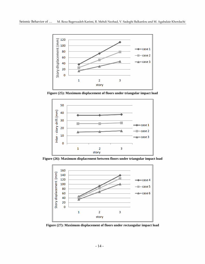
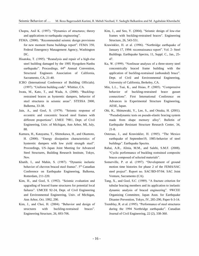
As Figures (25) and (27) show, the maximum
displacement of floors is close to the line in all cases.
As the rectangular impact load is applied with greater
intensity to the structure, the maximum displacement
of a rectangular load is larger than that of a triangular
load.
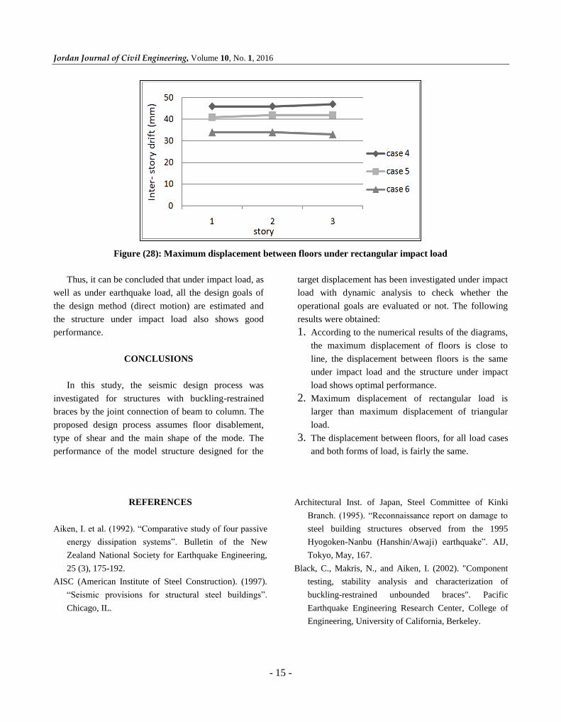
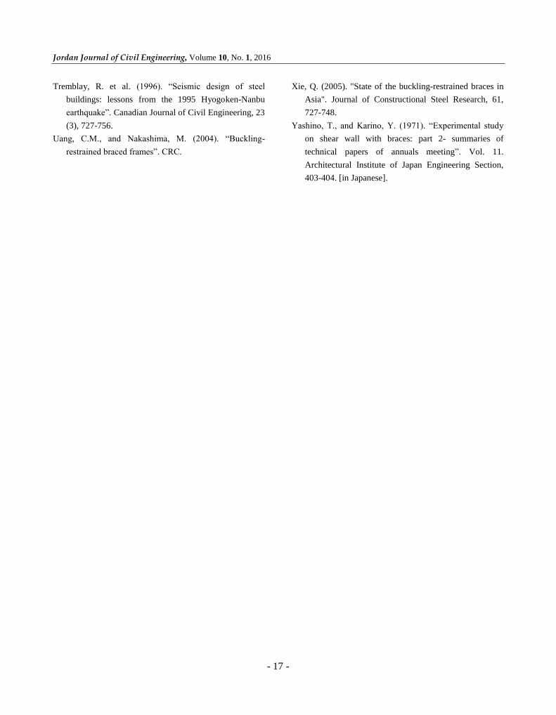
Also, according to Figures (26) and (28), it can be
concluded that the displacement between floors for all
loads and both forms of load is fairly the same.
Seismic Behavior of … M. Reza Bagerzadeh Karimi, R. Mehdi Nezhad, V. Sadeghi Balkanlou and M. Agabalaie Khordachi
- 14 -
Figure (25): Maximum displacement of floors under triangular impact load
Figure (26): Maximum displacement between floors under triangular impact load
Figure (27): Maximum displacement of floors under rectangular impact load
Jordan Journal of Civil Engineering, Volume 10, No. 1, 2016
- 15 -
Figure (28): Maximum displacement between floors under rectangular impact load
Thus, it can be concluded that under impact load, as
well as under earthquake load, all the design goals of
the design method (direct motion) are estimated and
the structure under impact load also shows good
performance.
CONCLUSIONS
In this study, the seismic design process was
investigated for structures with buckling-restrained
braces by the joint connection of beam to column. The
proposed design process assumes floor disablement,
type of shear and the main shape of the mode. The
performance of the model structure designed for the
target displacement has been investigated under impact
load with dynamic analysis to check whether the
operational goals are evaluated or not. The following
results were obtained:
1. According to the numerical results of the diagrams,
the maximum displacement of floors is close to
line, the displacement between floors is the same
under impact load and the structure under impact
load shows optimal performance.
2. Maximum displacement of rectangular load is
larger than maximum displacement of triangular
load.
3. The displacement between floors, for all load cases
and both forms of load, is fairly the same.
REFERENCES
Aiken, I. et al. (1992). “Comparative study of four passive
energy dissipation systems”. Bulletin of the New
Zealand National Society for Earthquake Engineering,
25 (3), 175-192.
AISC (American Institute of Steel Construction). (1997).
“Seismic provisions for structural steel buildings”.
Chicago, IL.
Architectural Inst. of Japan, Steel Committee of Kinki
Branch. (1995). “Reconnaissance report on damage to
steel building structures observed from the 1995
Hyogoken-Nanbu (Hanshin/Awaji) earthquake”. AIJ,
Tokyo, May, 167.
Black, C., Makris, N., and Aiken, I. (2002). "Component
testing, stability analysis and characterization of
buckling-restrained unbounded braces". Pacific
Earthquake Engineering Research Center, College of
Engineering, University of California, Berkeley.
Seismic Behavior of … M. Reza Bagerzadeh Karimi, R. Mehdi Nezhad, V. Sadeghi Balkanlou and M. Agabalaie Khordachi
- 16 -
Chopra, Anil K. (1997). “Dynamics of structures; theory
and applications to earthquake engineering”.
FEMA. (2000). “Recommended seismic design provisions
for new moment frame buildings report”. FEMA 350,
Federal Emergency Management Agency, Washington
DC.
Hisatoku, T. (1995). “Reanalysis and repair of a high-rise
steel building damaged by the 1995 Hyogoken-Nanbu
earthquake”. Proceedings, 64th Annual Convention,
Structural Engineers Association of California,
Sacramento, CA, 21-40.
ICBO (International Conference of Building Officials).
(1997). “Uniform building code”. Whittier, CA.
Iwata, M., Kato, T., and Wada, A. (2000). “Buckling-
restrained braces as hysteretic dampers, behavior of
steel structures in seismic areas”. STESSA 2000,
Balkema, 33-38.
Jain, A., and Goel, S. (1979). “Seismic response of
eccentric and concentric braced steel frames with
different proportions”. UMEE 79R1, Dept. of Civil
Engineering, Univ. of Michigan, Ann Arbor, MI, July,
88.
Kamura, H., Katayama, T., Shimokawa, H., and Okamoto,
H. (2000). “Energy dissipation characteristics of
hysteretic dampers with low yield strength steel”.
Proceedings, US–Japan Joint Meeting for Advanced
Steel Structures, Building Research Institute, Tokyo,
Nov.
Khatib, I., and Mahin, S. (1987). “Dynamic inelastic
behavior of chevron braced steel frames”. 5th Canadian
Conference on Earthquake Engineering, Balkema,
Rotterdam, 211-220.
Kim, H., and Goel, S. (1992). “Seismic evaluation and
upgrading of braced frame structures for potential local
failures”. UMCEE 92-24, Dept. of Civil Engineering
and Environmental Engineering, Univ. of Michigan,
Ann Arbor, Oct. 1992, 290.
Kim, J., and Choi, H. (2004). “Behavior and design of
structures with buckling-restrained braces”.
Engineering Structure, 26, 693-706.
Kim, J., and Seo, Y. (2004). "Seismic design of low-rise
frames with buckling-restrained braces". Engineering
Structure, 26, 543-551.
Krawinkler, H. et al. (1996). “Northridge earthquake of
January 17, 1994: reconnaissance report”. Vol. 2- Steel
Buildings. Earthquake Spectra, 11, Suppl. C., Jan., 25-
47.
Ku, W. (1999). “Nonlinear analyses of a three-storey steel
concentrically braced frame building with the
application of buckling-restrained (unbonded) brace”.
Dept. of Civil and Environmental Engineering,
University of California, Berkeley, CA.
Min, L.L., Tsai, K., and Hsiao, P. (2005). “Compressive
behavior of buckling-restrained brace gusset
connections”. First International Conference on
Advances in Experimental Structure Engineering,
AESE, Japan.
Ohi, K., Shimawaki, Y., Lee, S., and Otsuka, H. (2001).
“Pseudodynamic tests on pseudo-elastic bracing system
made from shape memory alloy”. Bulletin of
Earthquake Resistant Structure Research Center, 34,
21-8.
Osteraas, J., and Krawinkler, H. (1985). “The Mexico
earthquake of September19, 1985-behavior of steel
buildings”. Earthquake Spectra.
Rahai, A.R., Alinia, M.M., and Salehi, S.M.F. (2008).
“Cyclic performance of buckling restrained composite
braces composed of selected materials”.
Somerville, P. et al. (1997). “Development of ground
motion time histories for phase 2 of the FEMA/SAC
steel project”. Report no. SAC/BD-97/04. SAC Joint
Venture, Sacramento (CA).
Tang, X., and Goel, S.C. (1989). “A fracture criterion for
tubular bracing members and its application to inelastic
dynamic analysis of braced engineering”. 9WCEE
Organizing Committee, Japan Assn. for Earthquake
Disaster Prevention, Tokyo, IV, 285-290, Paper 6-3-14.
Tremblay, R. et al. (1995). “Performance of steel structures
during the 1994 Northridge earthquake”. Canadian
Journal of Civil Engineering, 22 (2), 338-360.
Jordan Journal of Civil Engineering, Volume 10, No. 1, 2016
- 17 -
Tremblay, R. et al. (1996). “Seismic design of steel
buildings: lessons from the 1995 Hyogoken-Nanbu
earthquake”. Canadian Journal of Civil Engineering, 23
(3), 727-756.
Uang, C.M., and Nakashima, M. (2004). “Buckling-
restrained braced frames”. CRC.
Xie, Q. (2005). "State of the buckling-restrained braces in
Asia". Journal of Constructional Steel Research, 61,
727-748.
Yashino, T., and Karino, Y. (1971). “Experimental study
on shear wall with braces: part 2- summaries of
technical papers of annuals meeting”. Vol. 11.
Architectural Institute of Japan Engineering Section,
403-404. [in Japanese].