Embed Size (px)
Citation preview

Proceedings IRF2018: 6th International Conference Integrity-Reliability-Failure
Lisbon/Portugal 22-26 July 2018. Editors J.F. Silva Gomes and S.A. Meguid
Publ. INEGI/FEUP (2018); ISBN: 978-989-20-8313-1
-1275-
PAPER REF: 7308
SEISMIC ANALYSIS OF THE IRREGULAR FIRE STATION
BUILDING OF L’AQUILA
Marco Scagnetti1, Rui C. Barros
2(*), Marco Mezzi
1
1Faculty of Civil and Environmental Engng of the University of Perugia, Italy
2Dept of Civil Engng (Structural Division), FEUP, University of Porto, Portugal
(*)Email: [email protected]
ABSTRACT
Following the seismic sequence that struck the city of L'Aquila in April 2009, the Fire Station
of the city, after the inspection of the technicians, was declared unfit for use. From subsequent
investigations of the structure, it proved to be seismically inadequate and it was decided for its
demolition and reconstruction with a significant planimetric redeployment. In the initial phase
of the work, it was carried out a study of the layout plans and of the loads imposed on the
floors. As a result of this investigation, it was decided to propose, as a structural solution for
the fire headquarter complex, a framed steel structure. The structure has been analyzed using
a finite element software with both linear and non-linear analysis. The possible structural
solution is achieved in accordance with the Eurocodes and, only with respect to the base
isolated building, according to the Italian standard called “Nuove Norme Tecniche delle
Costruzioni”. To meet the structural verifications required by design standards for the main
building of the complex, it was necessary to adopt a base isolation system. Among the various
solutions analyzed, the best was found to be that composed of elastomeric isolators and
multidirectional support. It was considered appropriate to use a fixed base for the other two
structures of the complex.
Keywords: critical building, metal structure, FEM analysis, base isolation, earthquake
resistant buildings.
INTRODUCTION
Inside the seismic sequence that struck the city of L'Aquila in 2009, the main shock occurred
on April 6 at 01:32:39 GMT, had a magnitude of Mw = 6.3 (Harvard CMT) and is found to be
generated by a fault with NW-SE trend. The quake was recorded by 55 stations of the
National Strong Motion Network, RAN. The East-West components of the time series
acceleration 4 stations at a maximum distance of 6 km from the epicenter show peaks greater
than 0.5 g (Ameri, 2009). The data recorded by the RAN network were available and it was
evaluated the effect acceleration time histories on the maximum of different elastic oscillators
answer period, thus obtaining the spectra response and highlighting so indirectly by the
content in this frequency in the data registered (Ameri, 2009) and (Chioccarelli, 2009). The
entire area was already the subject of seismic phenomena of similar or greater extent, still
well above the damage threshold. Particular similarity is found, to the affected areas and the
severity of the damage, with the event on February 2, 1703, as attested by historical sources
(Antinori, 1703)

Symp-13: Structural Dynamics and Control Systems. Theory, Experiments and Applications
-1276-
Structures were analyzed, using a finite element software, both with linear and non-linear
analysis. Linear analyzes are: modal analysis and response spectrum analysis; the non-linear
analysis performed are: Pushover analysis and nonlinear dynamic analyzes.
Finally, making necessary the introduction of an isolation system, were compared the results
relating to the use of three different solutions: elastomeric isolators and multidirectional
bearings, sliding bearings on the curved surface and a hybrid system made by laminating
elastomeric isolators and sliding supports of curved surface.
DESCRIPTION OF THE FIRE STATION COMPLEX
The provincial command of the Fire Brigade of L'Aquila is located in the eastern part of the
city and, specifically, in Via della Pescara. The complex consists of two components, the first,
which dates back to the early 60s and the second has been built since 2001. The entire
complex is made with the technology of reinforced concrete.
The complex object of studies, the most recently realization, is constituted by two buildings
and a tower for practice, separated by seismic joints to prevent the collision and allowing to
consider them as dynamically independent units, as shown in Figure 1.
Fig. 1 - Aerial view and plan diagram of the complex object of the intervention (A-Building;
B-Square; C-Tower) from (Provveditorato interregionale,2012)
What follows is a brief description of the factory buildings.
The construction identified as "Building" consists of 4 floors, with varying heights and a
cover on two distinct levels. The first level is partially buried. The plan of the building has an
L-shape in which, the main left wing dimensions are approximately 14.5 m to 48 m for a total
area of about 2700 m2 and is equipped with a stairwell with a lift for vertical connection while
those of the right side are approximately 14.5 m to 45 m for a total surface of approximately
2600 m2 and is equipped with two compartments scale for the vertical connection, only one
with elevator. The construction, in the basement, will be used as space for physical activities
train and local intended for archives and stores, will host the thermal plant and a ramp for
vehicle access to the part below the road level. The ground floor will house, in addition to the
main entrance in the left wing, a throw of the media on both sides. The third level will house
the offices open to the public in the left wing and laboratories in the right wing. The top floor
will be used as offices for the left side, while the right side, in addition to accommodation of
the commandant service, will be destined to the teaching premises. The building in addition to
presenting an irregular distribution of masses in height, for different functions to which they
are destined the floors, on the left side has a semi-circular planimetric dislocation
configuration in seismic area presents critical issues. Plan, also the distribution of the masses

Proceedings IRF2018: 6th International Conference Integrity-Reliability-Failure
-1277-
is uneven, especially at the level of the ground floor, having the same plane different
functions.
The body of the building identified as "Square" consists of a single level and is completely
below the road level. The main dimensions are approximately 34 m to 36 m for a total area of
approximately 1200 m2 and it is not equipped with stairwells for vertical connection. The
structure above the foundation plane will have the deposit feature and garage while the roof
will be destined to the square for the movement of vehicles and training activities. The
building has a regular distribution of the loads being destined to a single function but is not
regular in plan in that, the difference between the area enclosed by the perimeter of the plan
and that of a convex polygonal line that encloses the same plane is greater than the 5%.
The body of the building identified as "Tower" consists of five floors of equal height. The
first level is underground. The main dimensions of the building are approximately 6 m to 7 m,
for a total of about 210 m2 and is equipped with an internal staircase. The building is fully
used for training activities. The construction is regular both in height and in plan.
FINITE ELEMENT MODEL
The finite element analysis was carried out using the structural analysis program SAP2000
V.14.0.0 software. In modeling the component structures (A-B-C) by the models represented
in Figure 2, it was possible to consider them as dynamically independent units.
Fig. 2 - Physical and analytical model of Building (A), Square (B) and Tower (C), respectively
Each model has been developed with the blueprints available. The axes of the elements have
been made coincide with the centers of gravity of the pillars to the massively of foundations,
going to accomplish each of the model of the plant floor. This was left unchanged for each
floor not being present the eccentricity caused by the change of section of the pillars in the
passage from one level to another. From section, identified the interfloor heights as the height
between the center of gravity of two consecutive slabs, is realized the three-dimensional
model. Finally to match, as much as possible, the main directions of the building with the

Symp-13: Structural Dynamics and Control Systems. Theory, Experiments and Applications
-1278-
global coordinates X - Y of the software, they are rotated independent of the models angles
from each other. Only for the building called "Square" is have made three different rotations
to go to analyze the three main directions along which they are arranged the resistant elements
and the corresponding orthogonal directions. For all three configurations it has been
maintained the arrangement of the pillars described in (Scagnetti, 2015) that goes to optimize
the dynamic behavior of the body of the building.
The modeling is based on using one-dimensional finite element already present in the library
of software. Both for the beams to the pillars and the walls, is are used elements "frame",
finite element two-beam type of nodes where the deformability is also considered to cutting,
having a section equal to that of the actual elements. In general, it tried to reduce the
computational burden by not using "shells" elements while maintaining a good accuracy of
the solution.
The floors, as it may be considered infinitely rigid in their plan, were modeled as crushproof
plates in the horizontal plane. This assumption was made binding each plan node with a
"diaphragm" type constraint. For the roof, being on two levels, these are made of four distinct
constraints, one for each part, so that we then anchor the "master node" defined below. As for
the cross-behavior, being slightly disruptive to the assessment of the effects of seismic
actions, this has not been modeled.
The staircase, although with a not high contribution, helps to stiffen the structure and is
chosen to take this into account. The modeling was carried out with two elements "frame",
which connect the slabs to the landings, reflecting its geometry.
The slab loads, structural and permanent carried, were applied to the model by "shells"
elements with zero thickness as distributed loads unidirectional, using the option "uniform to
frame, one way", where the direction of application one coincides with the direction of the
"shell", because it is seen that, for this type of use does not increase the computational burden.
Even the accidental loads were applied with the same procedure. The wind and staircase load,
with its more accidental structural and carried permanent, are applied as linear loads directly
on the elements, distributing them through the method areas of influence of the respective
beams.
In the modeling of the walls with "frames" elements, to respect the maintenance hypothesis
the cross section plane, you have used the "end offset" option present in SAP2000 going to be
an infinitely rigid section. This option has proved performant because, in addition to a lower
computational burden which results in a shorter time of calculation, was closer to the behavior
you want to model remaining straight. Additionally, the software having the ability to
automatically vary the length of this portion based on the overlap between the elements
corresponding to the wall and the beam, is shall not define, for each variation of the length of
the wall, of the new nodes, to specify the length of the suddenly you want to keep is rigid,
thus proving a very versatile procedure.
The mass of the elements "frame", once assigned the characteristics of the material and
geometric properties of the elements, is calculated automatically by the software which, in
addition, through the "from load" option, derive the mass of the floor directly by the loads that
will they are applied.
In the analysis to consider it the accidental eccentricity as required by code has focused the
entire seismic mass of each floor, constituted by permanent and accidental loads weighing on
the floor and including that related to the upper and lower halves of the pillars, in a node
master, a node located in the geometrical center of gravity of the plane and eliminating the

Proceedings IRF2018: 6th International Conference Integrity-Reliability-Failure
-1279-
mass of the elements. Subsequently, through the construction of four additional models if they
have changed the position of the amount provided by the standard in order to be considered
accidental eccentricity of the loads.
In the linear analysis of the isolation devices, both as concern the elastomeric isolators that the
sliding bearings on the curved surface, were modeled as linear elements, resorting to the
characteristics of stiffness and equivalent damping while in the vertical direction, have been
impeded displacements, blocking the translation. The multidirectional supports were modeled
as elements with horizontal equivalent stiffness and equivalent damping null and prevented
vertical translation. In the analysis of non-linear, the hysteresis loop of elastomeric devices
has been approximated by a bilinear curve with appropriate parameters, as shown in Figure 3.
Fig. 3 - Approximation of the hysteresis loop of elastomeric isolators
DESCRIPTION OF THE STRUCTURAL SOLUTION
Square Structure
For this construction, the design process for reaching the final structural solution is started
whereas a steel frame and orienting the axis of greatest inertia of the pillars before along X
and along Y Failing to obtain a satisfactory dynamic behavior, for the ' eccentricity between
the center of the masses and the center of stiffness, it proceeded to direct only a part of the
pillars along X and the remaining long Y. In so doing, thanks to the containment of the
eccentricity shown in Figure 4.a, there was obtained a good dynamic behavior, as shown in
Figures 4(b) - 4(d).
(a) Eccentricity of the Square (b) Mode 1, T1=0.191 s
(c) Mode 2, T2=0.154 s (d) Mode 3, T3=0.134 s
Fig. 4 - Eccentricity of the Square structure and its mode shapes

Symp-13: Structural Dynamics and Control Systems. Theory, Experiments and Applications
-1280-
In fact, the first mode of vibration is of a purely translational along the Y direction, the second
way is also purely translational, but along X, while the third mode of vibration is of a purely
rotational type, going to excite with only 3 modes, 100% of the mass, as shown in Table 1.
Table 1 - Participants masses of the Square of the first configuration analyzed
Mode Period UX UY UZ SUX SUY SUZ
1 0,191225 0,00113 0,99853 5,749E-09 0,00113 0,99853 5,749E-09
2 0,153977 0,96487 0,00133 2,901E-10 0,96599 0,99985 6,039E-09
3 0,133531 0,034 0,00014 2,09E-10 1 1 6,248E-09
For the Square, since the results of the other two analyzed configurations are similar to those
shown, the final solution is made up of a frame system, made with beams and pillars in steel
and a mixed steel-concrete slab. This proposal can satisfy the checks and used sections are
summarized in Table 4.
Tower Structure
The tower has the staircase and an opening in the floor places laterally that move the center of
mass in the opposite direction, which is in the remaining part of the slab.
The iterative process to arrive at the final solution is started from the study of a steel frame,
where, in order to contain the displacements, of braces have been inserted in the inner sides of
the staircase body. The internal positioning instead of in front view, although not optimal, was
dictated by the interference that was emerging with windows. The second phase saw halve the
length of the braces in order to increase the critical load for buckling. Failing to obtain a good
dynamic behavior of the structure and to satisfy the tests, the concrete walls are in place, the
outer sides of the building. In doing so the eccentricity between the center of mass and center
of rigidity was contained, obtaining a certain degree of symmetry and ensuring the
satisfaction of the checks is to limit states that exercise over that a good dynamic behavior as
shown in Figures 5(a) - 5(d). The first mode of vibration is, in fact, purely translational along
Y, the second way is translational along X, with a negligible rotational component due to the
low value of the participant and a third rotational mass way. For the asymmetry due to the
disposition planimetric, to achieve the participating mass value provided by the standard,
equal to 90%, 8 modes must be considered, however modest value compared to a same
building made entirely of steel, as shown in Table 2.
Table 2 - Participants masses of the Tower
Mode Period UX UY UZ SUX SUY SUZ
1 0,365281 0,00007432 0,70605 0,0000199 0,00007432 0,70605 0,0000199
2 0,342196 0,68813 0,00009113 2,283E-09 0,6882 0,70614 0,0000199
3 0,22566 0,05699 0,00000849 1,092E-07 0,74519 0,70615 0,00002001
4 0,097788 0,14264 0,00018 4,816E-09 0,88783 0,70633 0,00002002
5 0,092878 0,00017 0,18079 0,00012 0,888 0,88712 0,00014
6 0,065583 0,00934 0,00003645 0,000007775 0,89733 0,88716 0,00014
7 0,048729 0,04959 1,413E-07 0,000002425 0,94693 0,88716 0,00015
8 0,042801 2,623E-07 0,06094 0,00514 0,94693 0,94809 0,00528

Proceedings IRF2018: 6th International Conference Integrity-Reliability-Failure
-1281-
(a) Eccentricity of the Tower (b) Mode 1, T1 =0.365 s
(c) Mode 2, T2=0.342 s (d) Mode 3, T3=0.226 s
Fig. 5 - Eccentricity of the Tower structure and its mode shapes
For the tower, the final solution is constituted by a large walls weakly armed in the X
direction and a dual structure in Y direction system, made with reinforced concrete walls,
steel beams and pillars and a mixed steel-concrete slab. This proposal can satisfy the checks
and used sections are summarized in Table 5.
BUILDING
Reaching the final configuration for the building has passed through many phases. Initially
this building has been thought to fixed base and with the two sides of the "L" separated by a
seismic joint, so as to avoid the concentration of stresses in the inner part of the angle.
The first structure of the building, the right wing of the "L" which we call here "Building 2",
has a regular plan, but the two staircases are not aligned, going to generate an eccentricity
between the center of stiffness and the center of the masses which makes the torsion sensible
building. To limit this effect, as well as to contain the displacements, of the braces in the
staircase bodies they have been inserted. For the presence of openings for the passage of the
vehicle, the braces cannot be established along the sides, a solution that would maximize its
effectiveness. However, the resulting sections of the latter are too large going to interfere with
the side elements of the ladder. It is appeal then, in the reinforced concrete walls, arranged in
a suitable position as shown in Fig. 6(a), thus managing to reduce the aforesaid eccentricity,
as shown in Figure 6(b), but failing to satisfy the verification at the ultimate limit state with
no commercial profile.
The second part, the left wing, which we will call "Building 1," has a semicircular planimetric
dislocation, which even if of very large radius do not make it particularly effective to
withstand seismic actions. In addition, this building has only one stairway which is located
laterally, resulting in a significant eccentricities. In this case, besides the presence of the
openings at the level of the ground floor, there are also the balconies on the upper floors
which constitute a further restriction. The reduction in this value was first sought by inserting
the steel braces and then are inserted perimeter of the septa in reinforced concrete to the level
below the road surface, together with the walls, always in reinforced concrete, in a suitable

Symp-13: Structural Dynamics and Control Systems. Theory, Experiments and Applications
-1282-
position as shown in Figure 6(c). The resulting effect is shown in Figure 6(d), but even in this
case it is not found a commercial profile that meets the verifications at the limit state
considered.
(a) Disposition of the walls in Building 2 (b) Eccentricity of Building 2
(c) Disposition of the walls in Building 1 (d) Eccentricity of Building 1
Fig. 6 - Disposition of the Walls I Building and its eccentricities
As just said, it was decided to isolate both buildings, still keeping them separate, and placing
the insulation level below the ground floor slab. We have chosen this position, not to create
differences in height between the Square and the floor of the buildings and be able to allow
the exit of the vehicles while you is not isolated to the above, that is, at the base of the first
level of the pillars, as it goes left free space around each pillar to enable its swing unhindered.
This solution, in addition to not optimize the use of the internal space, would expose the
isolators to chemicals such as gasoline or other, compatible with the function of the garage,
which may deteriorate their properties.
For the development of this solution, the main limitations were the ones to avoid the collision
between the various parts of the building, having the buildings at a distance so that you can
use a commercial joint cover and meet the ultimate limit state checks, by reducing stress
guaranteed by the insulation system.
The first devices used were elastomeric the isolators HDRB. With these devices could not
satisfy all the above conditions simultaneously, so it turned to elastomeric devices with lead
core LRB (FIP S03, 2013) in which, relying on a greater dissipation of energy, we have tried
to meet various restrictions. Even in this case he could satisfy only one condition at a time, for
which, the fixed distance of the buildings according to the joint cover, or the insulation
system had a stiffness such that they avoided or the collision but were not met the checks
envisaged from the norm or vice versa. This has led to think the two buildings as a single
building block, maintaining the same position of the insulation system of separate buildings.
The decoupling of the dynamic behavior of the substructure and overstructure of Building
was analyzed by three different isolation strategies. In the first has been considered a system
composed of elastomeric isolators for high damping HDRB and sliding supports

Proceedings IRF2018: 6th International Conference Integrity-Reliability-Failure
-1283-
multidirectional, in the second state is evaluated a system solely composed of curved surface
in sliding isolators with a low friction coefficient, also said "Friction Pendulum" and in the
third a hybrid system consisting of elastomeric isolators and "Friction Pendulum".
In the first seismic protection strategy, the insulation system consists of 33 elastomeric
isolators FIP of SI 1000/140 N-type (FIP S02, 2012) and 17 FIP supports multi-VM
1300/100/50 type (FIP B01, 2013). To contain the eccentricity in plan between the center of
masses of the superstructure and the center of rigidity of the insulation system, the
elastomeric isolators are arranged in the plant as shown in Figure 7 while, in correspondence
of the remaining pillars, have positioned the multidirectional bearings. This configuration is
reached initially by placing insulators perimeter position, for centrifuging the more the
rigidity and then varying it possible to obtain the optimum arrangement. In this way it is
obtained a distance between the two centers of 0.10 m along the X axis and 0.09 m along the
Y axis from the values given are contained torsional effects, as required by the standard and
get Eigen modes translational, as shown in the modal analysis results in Figures 8(a)-8(c), and
reaching almost the totality of the participating mass with only 3 mode, as shown in Table 3.
Fig. 7 - Position of elastomeric isolators and multidirectional bearings
Table 3 - Participants masses of the Building
Mode Period UX UY RZ SUX SUY SRZ
1 1,196254 0,90983 0,0732 0,15108 0,90983 0,0732 0,15108
2 1,18765 0,07855 0,83128 0,4433 0,98838 0,90448 0,59438
3 1,045283 0,00012 0,08663 0,39491 0,9885 0,99111 0,98929
(a) Mode 1, T1=1.19 s (b) Mode 2, T2=1.18 s (c) Mode 3, T3=1.04 s
Fig. 8 - Eccentricity of the Building structure and its mode shapes

Symp-13: Structural Dynamics and Control Systems. Theory, Experiments and Applications
-1284-
In use of the friction pendulum, for the own characteristics of the devices do not have the
above-mentioned eccentricity, so these were disposed in correspondence of all the pillars,
then going to employ devices 50 of the type FIP_D L 1650/500 (3100) (FIP S04, 2013),
where the letter "D" indicates that the devices are double curvature.
In both systems, the devices are subject to traction but, only for the system composed of
elastomeric isolators this can be absorbed by the anti-lifting devices connected to the columns
and the concrete slab. Between the two parts of the device it is allowed the relative sliding in
the horizontal direction while, in the vertical direction, absorb the traction and, therefore, acts
as a constraint, as shown in Figure 9(a). For the insulation system consists of the sliding
devices on curved surface these devices are not feasible given the presence of the vertical
displacements. An alternative solution consists of systems, integral with the ground, to put to
contrast and which are interposed between more devices, as shown in Figure 9(b). The
solution, from a theoretical point of view, it is advantageous in that it allows to insert
additional friction isolators that would allow an increase of the energy dissipation in the input,
but, in this case, it is not adoptable as the side where there is the Square, to realize the contrast
system would be to close the access of the vehicles below the Square, making it incompatible
with the intended function garage.
(a) Anti-lifting device (b) Example of contrast structure for Friction
pendulum subject to traction
Fig. 9 - Eccentricity of the Building structure and its mode shapes
Finally, as isolation strategy, it is also evaluated the possibility of using a hybrid system
composed by elastomeric isolators and "friction pendulum", which would replace the
multidirectional supports. The coupling portion advantage is due to the fact that, thanks to the
"Friction Pendulum", it has a greater dissipation of energy which consequently gives rise both
to minor displacements, so that those absolute interfloor those, which at a lower level of
stresses, both at the level of the superstructure that of the substructure. Another advantage is
given by the fact that, the "Friction Pendulum", do not change the position of the center of
stiffness of the isolation system. The system, although in theory it is very advantageous, for
this specific case, it is not possible to use, as such, not being able to vary the position of
elastomeric isolators for maintaining the good dynamic behavior, you have the possibility to
only take five isolators sliding on the curved surface, resulting in the other subject to traction.
In addition these devices, as mentioned previously, are incompatible with the anti-lifting
devices designed to absorb the traction agent of elastomeric isolators.
For the building, the final solution is constituted by an isolated structure with a superstructure
consisting of a frame system, composed by steel beams and pillars and a substructure made up
of reinforced concrete pillars. The attic floor above the insulation is realized by means of a
Proceedings IRF2018: 6th International Conference Integrity-Reliability-Failure
-1285-
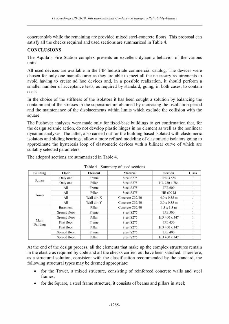
concrete slab while the remaining are provided mixed steel-concrete floors. This proposal can
satisfy all the checks required and used sections are summarized in Table 4.
CONCLUSIONS
The Aquila’s Fire Station complex presents an excellent dynamic behavior of the various
units.
All used devices are available in the FIP Industriale commercial catalog. The devices were
chosen for only one manufacturer as they are able to meet all the necessary requirements to
avoid having to create ad hoc devices and, in a possible realization, it should perform a
smaller number of acceptance tests, as required by standard, going, in both cases, to contain
costs.
In the choice of the stiffness of the isolators it has been sought a solution by balancing the
containment of the stresses in the superstructure obtained by increasing the oscillation period
and the maintenance of the displacements within limits which exclude the collision with the
square.
The Pushover analyzes were made only for fixed-base buildings to get confirmation that, for
the design seismic action, do not develop plastic hinges in no element as well as the nonlinear
dynamic analyzes. The latter, also carried out for the building based isolated with elastomeric
isolators and sliding bearings, allow a more refined modeling of elastomeric isolators going to
approximate the hysteresis loop of elastomeric devices with a bilinear curve of which are
suitably selected parameters.
The adopted sections are summarized in Table 4.
Table 4 - Summary of used sections
Building Floor Element Material Section Class
Square Only one Frame Steel S275 IPE O 550 1
Only one Pillar Steel S275 HL 920 x 784 1
Tower
All Frame Steel S275 IPE 600 1
All Pillar Steel S275 HE 600 M 1
All Wall dir. X Concrete C32/40 4,0 x 0,35 m /
All Wall dir. Y Concrete C32/40 3,0 x 0,35 m /
Main
Building
Basement Pillar Concrete C32/40 1,3 x 1,3 m /
Ground floor Frame Steel S275 IPE 500 1
Ground floor Pillar Steel S275 HD 400 x 347 1
First floor Frame Steel S275 IPE 450 1
First floor Pillar Steel S275 HD 400 x 347 1
Second floor Frame Steel S275 IPE 400 1
Second floor Pillar Steel S275 HD 400 x 347 1
At the end of the design process, all the elements that make up the complex structures remain
in the elastic as required by code and all the checks carried out have been satisfied. Therefore,
as a structural solution, consistent with the classification recommended by the standard, the
following structural types may be deemed appropriate:
• for the Tower, a mixed structure, consisting of reinforced concrete walls and steel
frames;
• for the Square, a steel frame structure, it consists of beams and pillars in steel;

Symp-13: Structural Dynamics and Control Systems. Theory, Experiments and Applications
-1286-
• for the building, an isolated structure, with an insulation system consisting of
elastomeric isolators and sliding bearings located at the top of the pillars in reinforced
concrete of the substructure and a superstructure consists of a steel frame;
The section of the pillars of reinforced concrete substructure is generous and highly
reinforced. This is due both to the need of the elements to remain in the elastic range, and to
the fact that, to limit the displacements of the superstructure and have no collision with the
Square, the stiffness of the devices is relatively high, being only sufficient to reduce the forces
in the superstructure but not to completely decouple the superstructure from the substructure.
For the other elements of the complex it was not considered necessary for the introduction of
an isolation system and the checks have been satisfied with commercial profiles. In addition
to the Piazzale they would have two additional disadvantages: an increase in costs linked to
the insulators, as it would be to isolate only a slab, being constituted by a single plane and
would have problems of availability of the joint covers, making necessary an enlargement of
the seismic coupling between the Building and the Square.
REFERENCE
[1] Antinori A L, Annali degli Abruzzi. 1703, vol. XXIV.
[2] Chioccarelli E, De Luca F, Iervolino I. Preliminary study of L’Aquila earthquake ground
motion records. Report V5.20, 2009, http://www.reluis.it/.
[3] FIP Industriale (Gennaio 2013): S03 Catalogo isolatori elastomerici con nucleo in
piombo. http://www.fipindustriale.it/index.php.
[4] FIP Industriale (Maggio 2012): S02 Catalogo isolatori elastomerici. http://www.
fipindustriale.it/index.php.
[5] FIP Industriale (Gennaio 2013): B01 Catalogo appoggi multidirezionali..
http://www.fipindustriale.it/index.php.
[6] FIP Industriale (Maggio 2013): S04 Catalogo isolatori a scorrimento su superficie curva.
http://www.fipindustriale.it/index.php.
[7] Provveditorato interregionale OO.PP. per il Lazio, l’Abruzzo e la Sardegna (2012):
Lavori per la ricostruzione di immobili della parte vecchia della sede del comando provinciale
danneggiato dal sisma del 06.04.2009 - Progetto preliminare. Ministero delle Infrastrutture e
dei Trasporti.
[8] Scagnetti, M. “Analisi Sismica della Nuova Caserna dei Vigili del Fuoco de L’Aquila”. MSc thesis in structural engineering, Dept Civil Engineering (DEC), Faculdade de Engenharia (FEUP), Porto, Portugal, July 2015, (in Italian).

![DETECTION OF DEFECTS IN COMPOSITE HELMETS USING …irf/Proceedings_IRF2018/data/papers/7143.pdf[4] Wang Y.M., Wu Q. Experimental Detection of Composite Delamination Damage based on](https://img.pdfslide.us/doc/110x75/5f0341257e708231d4084d98/detection-of-defects-in-composite-helmets-using-irfproceedingsirf2018datapapers7143pdf.jpg)