Embed Size (px)
Citation preview
Proceedings IRF2018: 6th International Conference Integrity-Reliability-Failure
Lisbon/Portugal 22-26 July 2018. Editors J.F. Silva Gomes and S.A. Meguid
Publ. INEGI/FEUP (2018); ISBN: 978-989-20-8313-1
-615-
PAPER REF: 7248
IMPACT OF PREVENTIVE MAINTENANCE ON FLEXIBLE PAVEMENT SERVICE LIFE Manuel Ruíz1(*), Luís Ramírez1, Fermín Navarrina1, J.R. Fernández de Mesa1, David López-Navarrete2, Mario Aymerich2 1Grupo de Métodos Numéricos en Ingeniería (GMNI), E.T.S.I. Caminos Canales y Puertos, University of A Coruña, A Coruña, Spain 2European Investment Bank (EIB), Luxembourg (*)
Email: [email protected] ABSTRACT
This work presents a numeric model for the calculation of the estimated service lifetime of flexible pavements taking into account dynamic axle loads. The work is focus on the evolution of the International Roughness Index (IRI) and fatigue damage along flexible pavements service lifetime, and the effects of different maintenance strategies on these two factors. The process and its sub processes are presented in this paper, explaining their respective role into the model. The model was programmed into a software called “Dynamic & Maintenance Simulation App (DMSA)”.
Keywords: flexible pavements, fatigue analysis, maintenance, numeric models in engineering, dynamic axle loads.
INTRODUCTION
Road transport is a key element for the economic growth and development in modern societies. For example, in the European Union, road infrastructures are a fundamental element of social cohesion and prosperity, representing about 45% of the transported goods and over 80% of the passengers in the EU. However, due to the economic crisis, the maintenance expenditure of the European countries had suffered, according to the OECD, a reduction of over 30% between 2008 and 2011.
Nowadays, many national highway agencies recognize the importance of an adequate preventive maintenance during the road pavement life-cycle. It is believed that if preventive maintenance is programmed to be applied too infrequently the maintenance and user costs will increase. On the contrary, if it is applied too frequently the maintenance program cost will be reduced, but due the traffic interruption there are costs in terms of user delay and inconvenience.
In this work, the effect of preventive maintenance on flexible pavement lifetime considering dynamic axle loads (Navarrina et al., 2015 [1]) is analyzed. All the essential factors (traffic, weather conditions, the specific fatigue law under consideration, the structural characteristics of the pavement, the project lifetime, etc.) are included in the proposed formulations.
The schematic process is divided in three different sub processes, each one intended for the calculation of a specific function (Pavement Deterioration Model, Dynamic Load Amplification factor and Accumulated Fatigue Damage indicator).
Topic-I: Civil and Structural Engineering Applications
-616-
Pavement Deterioration Model: Since the International Roughness Index (IRI) is a worldwide accepted concept, its variation over time is chosen as the representative variable of the progressive deterioration of the road profile. The model used for computing the evolution of the IRI over time can take into account multiple effects, such as the vehicles’ characteristics, the initial road profile, the structural specifications of the pavement and the project lifetime, among others.
Dynamic Load Amplification factor: The DLA factor quantifies the increase in the loads transmitted to the pavement due to the dynamic effects (caused by the pavement deterioration). The proposed model, called “Quarter Heavy Vehicle (QHV)” model, was developed by Navarrina et al. in 2015 [1] as a variant of the “Quarter Car (QC)” model [2], which is routinely used to calculate the IRI.
Accumulated Fatigue Damage indicator: This parameter quantifies the fatigue damage suffered by the pavement along its lifetime, which is the main indicator of the loss of structural integrity of the firm. The essential parameter for computing this indicator is the so-called reference strain (εr). In this work, we have used a “Multi-layer Elastic Model” based on Burmister model [3].
The computational models used in this work for the different phenomena that are involved in pavement deterioration are the bases of the software developed, named as “Dynamic & Maintenance Simulation App (DMSA)”. Some of the above mentioned methods require intensive computing, which makes them too costly for practical purposes. For this reason, the intention of the author is to provide fast-calculation expressions that yield similar results, which calibration is being performed at this time. It is obvious that faster calculations will allow a better interaction between the user and the tool.
PAVEMENT DETERIORATION MODEL
The main objective of the PDM is to simulate the time evolution of the superficial roughness for a given flexible paved road. This evolution is needed for the study of different maintenance scenarios and their effects into the lifetime of the firm.
Several deterioration models can be found in the literature, each one with its own advantages and disadvantages. As result of a deep study of an index, which is widely used in the vast majority of the countries where road networks containing flexible paved roads are currently under maintenance, monitoring or planning, IRI was found to be the most extended one. IRI was developed by the World Bank in 1986 with the intention of establish the overall use of an index to measure surface roughness on roads worldwide. IRI is obtained from measured longitudinal profiles, and also, is being widely used as an user’s comfort indicator, and even, used in economic studies concerning fuel consumption cost per kilometer in roads.
The PDM finally selected for this project simulates the IRI evolution over time produced by the deterioration of the upper bituminous layer of a flexible paved road, and it is based on HDM-III (Highway Design and Maintenance standards model III). It takes into account the weather conditions of the region where the road analyzed is located, the initial conditions of the road (roughness and structural properties), traffic and also previous rehabilitation or maintenance works. This model was called the “D.0” by Paterson in 1992 [4]. The equation of this PDM reads
IRIT = 1.04 emT [IRI0 + 263 (1 + SNC)-5 NET ]
where:
Proceedings IRF2018: 6th International Conference Integrity-Reliability-Failure
-617-
IRIT = roughness at pavement age T (m/km)
IRI0 = initial roughness (m/km)
NET = cumulative ESALs (Equivalent Single Axle Load) at age T (million ESAL/lane)
T =pavement age since rehabilitation or construction (years)
m = environmental coefficient
SNC = Structural Number modified Coefficient for subgrade strength
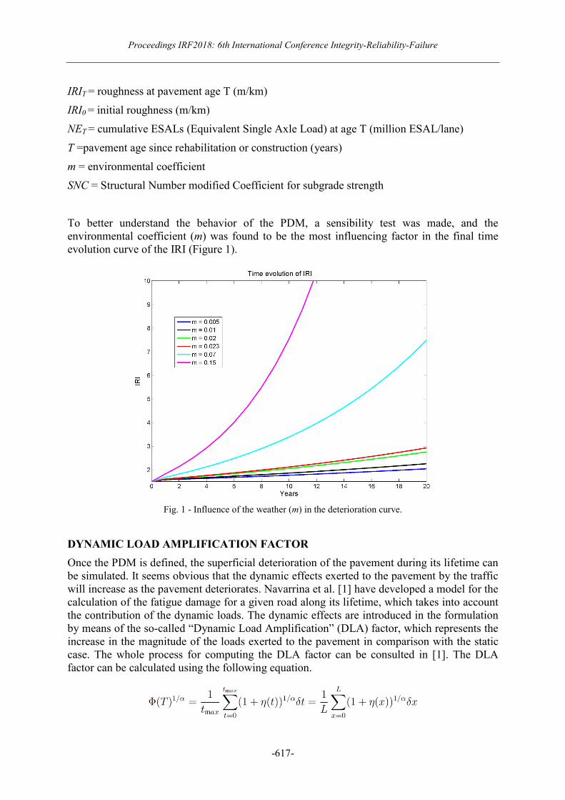
To better understand the behavior of the PDM, a sensibility test was made, and the environmental coefficient (m) was found to be the most influencing factor in the final time evolution curve of the IRI (Figure 1).
Fig. 1 - Influence of the weather (m) in the deterioration curve.
DYNAMIC LOAD AMPLIFICATION FACTOR
Once the PDM is defined, the superficial deterioration of the pavement during its lifetime can be simulated. It seems obvious that the dynamic effects exerted to the pavement by the traffic will increase as the pavement deteriorates. Navarrina et al. [1] have developed a model for the calculation of the fatigue damage for a given road along its lifetime, which takes into account the contribution of the dynamic loads. The dynamic effects are introduced in the formulation by means of the so-called “Dynamic Load Amplification” (DLA) factor, which represents the increase in the magnitude of the loads exerted to the pavement in comparison with the static case. The whole process for computing the DLA factor can be consulted in [1]. The DLA factor can be calculated using the following equation.
Topic-I: Civil and Structural Engineering Applications
-618-
Where tmax is the time that takes the heavy vehicle to reach at the end of the interval studied, η(t) is the dynamic amplification function, α is aconstant coefficient depending on the hot-mix asphalt type, L is the length of the road profile, and δt and δx are the length of the sample intervals in terms of time and distance, respectively.
Because, the model needs the road profile p(x) to calculate the DLA factor, it would be necessary to provide frequent measures of the profile of each road being analyzed, in order to achieve acceptable and realistic results. Since this is not practical, a model to simulate artificial road profiles for a given IRI value was developed in this work. The fundamentals of this model are presented below.
Road Profile Simulation Model
The road profile p(x) is introduced in the dynamic model by means of its Laplace transform P(ξ)
which can be expressed in polar form
The modulus of the Laplace Transform can be written in relation to the Power Spectral Density (PSD) function, denoted as Gd(n), as
The geometry of the road profile can be simulated if the PSD is known. In this work, we have used the “displacement Power Spectral Density”. For this PSD, the ISO 8608:2016 [5] recommends the use of the so-called straight line fitting, which uses a two parameter spectrum to describe the road profile.
In this equation, Gd is the PSD of vertical displacements, n is the spatial frequency, while n0 and Gd(n0) are values established in the standard ISO 8608 in order to facilitate the comparison between different road roughness profiles.
It is possible to generate an artificial road profile from a stochastic representation. This stochastic process can be described in terms of the Power Spectral Density of vertical displacements obtained through the Fourier Transform of the auto-correlation function. The value of the Power Spectral Density function, assuming a continuous road profile, for a defined value of spatial frequency n, within a frequency band ∆n, is defined as:
where ϒx2 is the mean square value of the component of the signal for the spatial frequency n,
cantered within a frequency band ∆n [6].
In the other hand, the road profile can be simulated from a simple harmonic function according to [7]:
Proceedings IRF2018: 6th International Conference Integrity-Reliability-Failure
-619-
where:
N ≡ L/B
L ≡Length of road profile
B ≡ Sampling interval
∆n ≡ Discretized frequency increment (1/L)
n0 ≡ Reference spatial frequency (0.1 cycles/m)
x ≡ Spatial variable for the ride ranging from 0 to L
φj ≡ Random phase angle uniformly distributed within the 0-2 π range A number of simulations were run with the objective to find a relationship between Gd(n0)
and the resulting IRI associated to the profile. This relationship is presented in the next equation.
ACCUMULATED FATIGUE DAMAGE INDICATOR
Finally, and once the previous models are defined, we need to determine the fatigue failure of the pavement. To this end, the accumulated fatigue damage indicator is presented.
Miner [8], expressed mathematically the concept of fatigue damage by means of the formula
which quantifies the total accumulated fatigue damage D that is reached when different loads are repeatedly applied in different proportions, where ni is the actual number of cycles of each load and Ni is the total number of cycles needed to reach the fatigue failure when only load i is applied.
The ratio between the actual number of cycles and the number of cycles to failure can be used as an indicator of the accumulated fatigue damage caused by one single load repeatedly applied.
The strain-based fatigue model of a hot-mix asphalt pavement can by expressed as
where N is the number of load cycles to failure, ϵr is the reference strain, which quantifies the structural damage caused by one single load and, K and α are coefficients that depend on the hot-mix asphalt type.
According to [1], the dynamic counterpart of the accumulated fatigue damage indicator can be written as
Topic-I: Civil and Structural Engineering Applications
-620-
where T is the time, Tp is the project lifetime, τ is the nondimensional time when T is scaled in relation to Tp, and Ed is the dynamic loading counterpart of the equivalent project traffic.
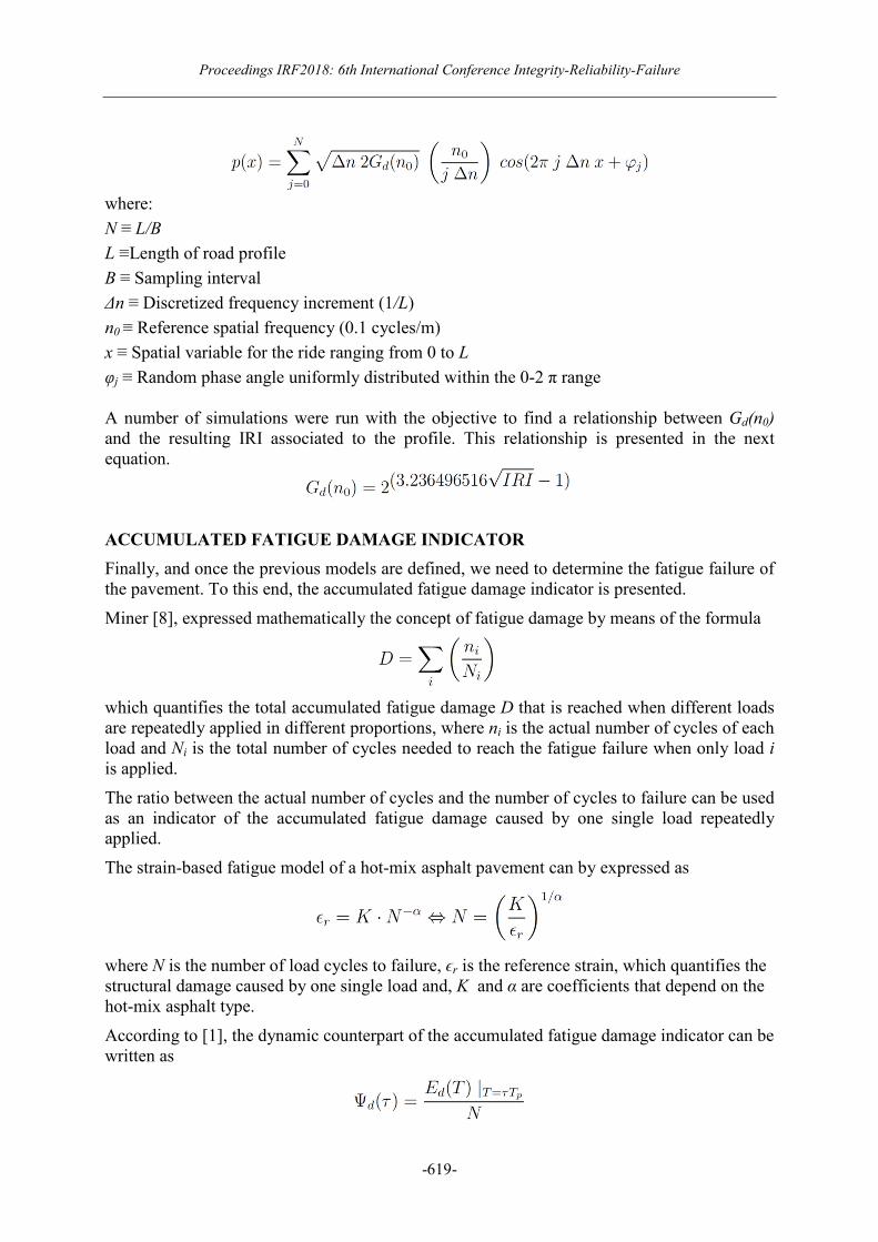
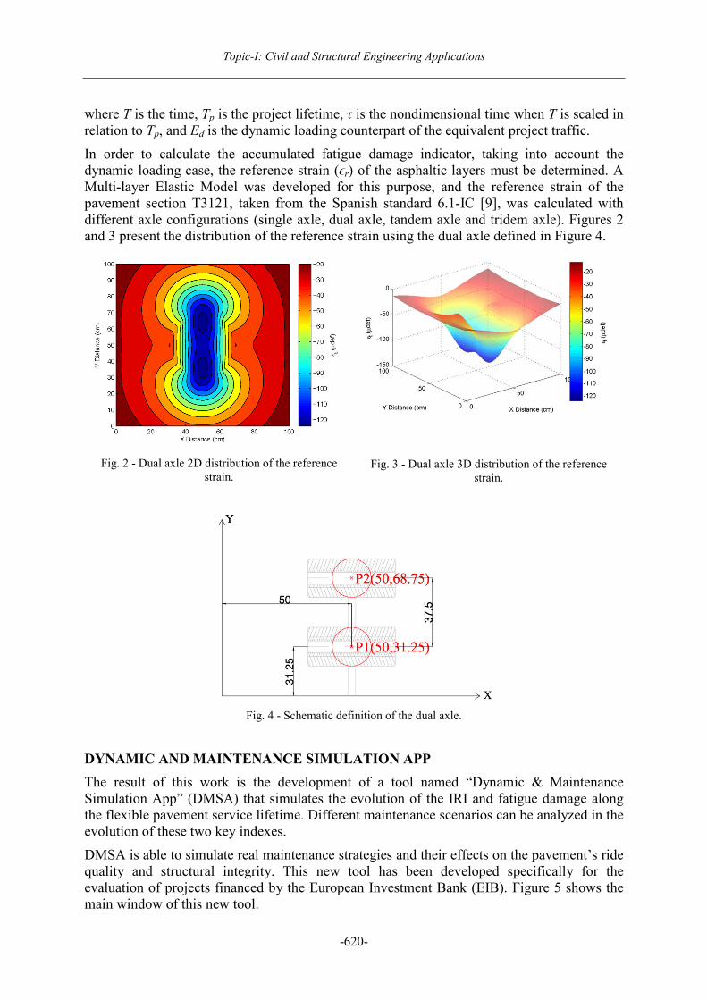
In order to calculate the accumulated fatigue damage indicator, taking into account the dynamic loading case, the reference strain (ϵr) of the asphaltic layers must be determined. A Multi-layer Elastic Model was developed for this purpose, and the reference strain of the pavement section T3121, taken from the Spanish standard 6.1-IC [9], was calculated with different axle configurations (single axle, dual axle, tandem axle and tridem axle). Figures 2 and 3 present the distribution of the reference strain using the dual axle defined in Figure 4.
Fig. 2 - Dual axle 2D distribution of the reference
strain.
Fig. 3 - Dual axle 3D distribution of the reference strain.
Fig. 4 - Schematic definition of the dual axle.
DYNAMIC AND MAINTENANCE SIMULATION APP
The result of this work is the development of a tool named “Dynamic & Maintenance Simulation App” (DMSA) that simulates the evolution of the IRI and fatigue damage along the flexible pavement service lifetime. Different maintenance scenarios can be analyzed in the evolution of these two key indexes.
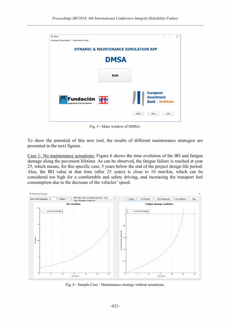
DMSA is able to simulate real maintenance strategies and their effects on the pavement’s ride quality and structural integrity. This new tool has been developed specifically for the evaluation of projects financed by the European Investment Bank (EIB). Figure 5 shows the main window of this new tool.
Proceedings IRF2018: 6th International Conference Integrity-Reliability-Failure
-621-
Fig. 5 - Main window of DMSA.
To show the potential of this new tool, the results of different maintenance strategies are presented in the next figures.
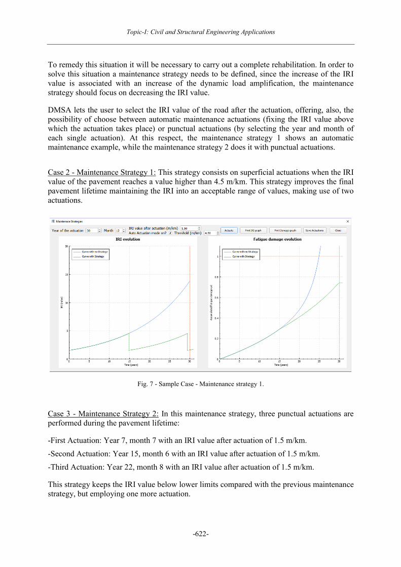
Case 1- No maintenance actuations: Figure 6 shows the time evolution of the IRI and fatigue damage along the pavement lifetime. As can be observed, the fatigue failure is reached at year 25, which means, for this specific case, 5 years below the end of the project design life period. Also, the IRI value at that time (after 25 years) is close to 10 mm/km, which can be considered too high for a comfortable and safety driving, and increasing the transport fuel consumption due to the decrease of the vehicles’ speed.
Fig. 6 - Sample Case - Maintenance strategy without actuations.
Topic-I: Civil and Structural Engineering Applications
-622-
To remedy this situation it will be necessary to carry out a complete rehabilitation. In order to solve this situation a maintenance strategy needs to be defined, since the increase of the IRI value is associated with an increase of the dynamic load amplification, the maintenance strategy should focus on decreasing the IRI value.
DMSA lets the user to select the IRI value of the road after the actuation, offering, also, the possibility of choose between automatic maintenance actuations (fixing the IRI value above which the actuation takes place) or punctual actuations (by selecting the year and month of each single actuation). At this respect, the maintenance strategy 1 shows an automatic maintenance example, while the maintenance strategy 2 does it with punctual actuations.
Case 2 - Maintenance Strategy 1: This strategy consists on superficial actuations when the IRI value of the pavement reaches a value higher than 4.5 m/km. This strategy improves the final pavement lifetime maintaining the IRI into an acceptable range of values, making use of two actuations.
Fig. 7 - Sample Case - Maintenance strategy 1.
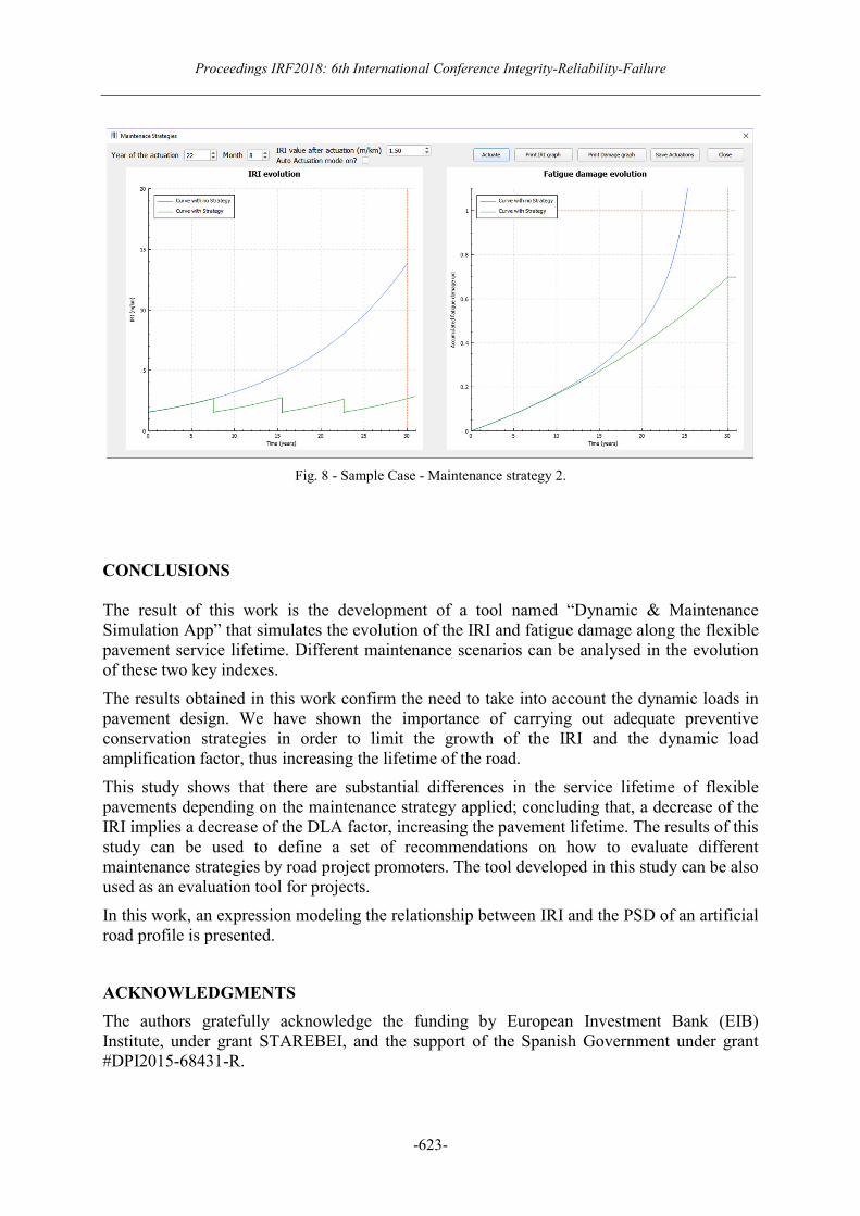
Case 3 - Maintenance Strategy 2: In this maintenance strategy, three punctual actuations are performed during the pavement lifetime:
-First Actuation: Year 7, month 7 with an IRI value after actuation of 1.5 m/km.
-Second Actuation: Year 15, month 6 with an IRI value after actuation of 1.5 m/km.
-Third Actuation: Year 22, month 8 with an IRI value after actuation of 1.5 m/km.
This strategy keeps the IRI value below lower limits compared with the previous maintenance strategy, but employing one more actuation.
Proceedings IRF2018: 6th International Conference Integrity-Reliability-Failure
-623-
Fig. 8 - Sample Case - Maintenance strategy 2.
CONCLUSIONS The result of this work is the development of a tool named “Dynamic & Maintenance Simulation App” that simulates the evolution of the IRI and fatigue damage along the flexible pavement service lifetime. Different maintenance scenarios can be analysed in the evolution of these two key indexes.
The results obtained in this work confirm the need to take into account the dynamic loads in pavement design. We have shown the importance of carrying out adequate preventive conservation strategies in order to limit the growth of the IRI and the dynamic load amplification factor, thus increasing the lifetime of the road.
This study shows that there are substantial differences in the service lifetime of flexible pavements depending on the maintenance strategy applied; concluding that, a decrease of the IRI implies a decrease of the DLA factor, increasing the pavement lifetime. The results of this study can be used to define a set of recommendations on how to evaluate different maintenance strategies by road project promoters. The tool developed in this study can be also used as an evaluation tool for projects.
In this work, an expression modeling the relationship between IRI and the PSD of an artificial road profile is presented.
ACKNOWLEDGMENTS
The authors gratefully acknowledge the funding by European Investment Bank (EIB) Institute, under grant STAREBEI, and the support of the Spanish Government under grant #DPI2015-68431-R.
Topic-I: Civil and Structural Engineering Applications
-624-
REFERENCES
[1] Navarrina F., Ramírez L., París J., Nogueira X., Colominas I., Casteleiro M., Fernández de Mesa J.R., A Comprehensive Model for Fatigue Analysis of Flexible Pavements Considering Effects of Dynamic Axle Loads. Transportation Research Record (TRR), Journal of the Transportation Research Board, 2524; pp. 110-118, (2015).
[2] Gillespie, T.D., M.W. Sayers, and L. Segel. NCHRP Report 228: Calibration of Response-Type Road Roughness Measuring Systems. TRB, National Research Council, Washington, D.C., (1980).
[3] Burmister, D.M, The General Theory of Stresses and Displacements in Layered Systems. Journal of Applied Physics, Vol. 16; pp. 89-94, (1998).
[4] W.D.O. Paterson and B. Attoh-Okine, Summary Models of Paved Road Deterioration Based on HDM-III. Transportation Research Record (TRR), Journal of the Transportation Research Board, 1244; pp. 99-105, (1992).
[5] International Organization for Standardization, ISO 8608:2016(E), Mechanical vibration - road surface profiles - reporting of measured data, (2016).
[6] J.S. Bendat and A.G. Piersol, Random Data: Analysis and Measurement Procedures, 4th Edition, Wiley, New York, (2010).
[7] M. Agostinacchio, D. Ciampa, S. Olita, The vibrations induced by surface irregularities in road pavements - a Matlab approach, European Transport Research Review, Vol. 6, No 3; pp. 267-275,(2014).
[8] Miner, M.A., Cumulative Damage in Fatigue, Journal of Applied Mechanics, 67, A159, (1945).
[9] Dirección General de Carreteras, Secretaría de Estado de Infraestructuras. Norma 6.1-IC “Secciones de Firme” de la Instrucción de Carreteras. Orden FOM/3460/2003 de 28 de noviembre (BOE de 12 de diciembre de 2003). Centro de Publicaciones del Ministerio de Fomento, Gobierno de España, (2003).


![DETECTION OF DEFECTS IN COMPOSITE HELMETS USING …irf/Proceedings_IRF2018/data/papers/7143.pdf[4] Wang Y.M., Wu Q. Experimental Detection of Composite Delamination Damage based on](https://img.pdfslide.us/doc/110x75/5f0341257e708231d4084d98/detection-of-defects-in-composite-helmets-using-irfproceedingsirf2018datapapers7143pdf.jpg)