Embed Size (px)
Citation preview

International Research Journal of Engineering and Technology (IRJET) e-ISSN: 2395 -0056
Volume: 02 Issue: 06 | Aug-2015 www.irjet.net p-ISSN: 2395-0072
© 2015, IRJET ISO 9001:2008 Certified Journal Page 214
SEISMIC ANALYSIS OF RC MULTI-STORIED STRUCTURES WITH
SHEAR WALLS AT DIFFERENT LOCATIONS
Sachin.P.Dyavappanavar1, Dr. K.Manjunatha.2, Kavya N3
1 Post Graduate Student In CAD Structural Engineering, Dept of Civil Engineering, University BDT college of
Engineering Davanagere, Karnataka, India
2 Professor, Dept of Civil Engineering, University BDT college of Engineering Davanagere, Karnataka, India
3 Post Graduate Student In CAD Structural Engineering, Dept of Civil Engineering, University BDT college of Engineering Davanagere, Karnataka, India
---------------------------------------------------------------------***---------------------------------------------------------------------Abstract -Shear wall is an basic important structural
component. These walls can be utilized for giving more
strength & safety to the structure, when the structures
are subjected to external loads, such as earthquake
loads, wind loads etc. the these type of walls , basically
play a main role for the construction of tall structure. In
the present study, the buildings with different number
of stories i.e, 20 storie building is considered for the
investigation of structure. These buildings are assumed
to be situated in zone IV. These are analyzed by
changing the positions of shear walls symmetrically by
considering different shape and locations of the shear
walls in buildings.
Key Words: Shear wall, ETABS, different shape & locations, Equivalent static method, response spectrum analysis, time history analysis, 1. INTRODUCTION 1.1 General Seismic waves reasons arbitrary ground motions in all possible directions, transmitting from the epicentre. If the structure has not been designed to resist these additional forces it may fail causing loss of life and property. In this way the impacts of sidelong loads like wind loads, quake forces & impact loads, etc. are achieving growing significance and every design engineer will face the issue of giving sufficient strength & stability for the structures against the imposed total lateral loads.
1.2 Shear wall Shear walls are utilized to withstand the bending moments of a building, because of lateral loads. They act as vertical cantilevers to give the essential stiffness in a building. Shear deformation are of course present but are negligible compared to bending wall rather than a shear wall. They
are usually given between columns, in stairs, lift walls, etc, in the structures under seismic forces. However since recent observations have shown consistency the excellent performance of building with shear walls under seismic forces, such wall are now extensively used for all earthquake resistance designs. 2. METHODOLOGY To determine the basic components like displacement and base shear this analysis has been carried using the software ETABS V 9.7.1. for the analysis purpose Equivalent static method, Response spectrum method and time history methods are adopted. 2.1 BUILDING MODELING In this building model RC multi storied structures of 20 stories is considered with shear walls of different locations like L shape, Rectangular shape, semi core and bare frame.the bottom stories height is 4.4m and the rest stories means upper stories’ height is kept constant as 3.2m for the building models, properties of the considered building models are detailed below here. 2.2 Material Properties The materials used for analysis of building models construction is reinforced concrete with m-25grade of concrete and fe-415 grade of steel. and the stress-strain relationship is used as per is 456:2000. the basic material properties are in given table 1.
Material Properties Values
Characteristic strength of concrete, fck 25 MPa
Yield stress for steel, fy 415 MPa
Modulus of Elasticity of steel, Es 20,0000 MPa
Modulus of Elasticity of concrete, Ec 25000 MPa
2.3 SECTION PROPERTIES:

International Research Journal of Engineering and Technology (IRJET) e-ISSN: 2395 -0056
Volume: 02 Issue: 06 | Aug-2015 www.irjet.net p-ISSN: 2395-0072
© 2015, IRJET ISO 9001:2008 Certified Journal Page 215
The section properties of four storied building model are given in table 2. Thickness of slab 0.15 m
Beam size 0.25 x 0.45 m
Column size 0.45 x 0.45 m
Thickness of wall 0.23 m
Thickness of shear wall 0.15 m
Assumed dead load intensities
Roof finishes 1 kN/m²
Floor finishes 1 kN/m²
Live load intensities
Roof 1.5 kN/m²
Floor 3.0 kN/m² 2.4 Geometry of the Considered Model: The geometry of the building of 20 storied building model are given in table 3. No. of Storeys
No. Bays in X direction
Bay width in X direction
No. of Bays in Y direction
Bay width in Y direction
Bottom Storey Ht
Storey Ht
20 5 5 m 5 5 m 4.4 m 3.2m
2.5 Plans and models
Plans and 3d models considered for the analysis purpose shear walls with different shape and different locations in the building
The plan and 3d model of the G+19 bare frame building (model 1)
The plan and 3d model the G+19 building shear wall at exterior corner (model 2)
The plan and 3d model of the G+19 building shear wall at interior corner(model 3)
The plan and 3d model of the G+19 building shear wall at mid frame(model4)
International Research Journal of Engineering and Technology (IRJET) e-ISSN: 2395 -0056
Volume: 02 Issue: 06 | Aug-2015 www.irjet.net p-ISSN: 2395-0072
© 2015, IRJET ISO 9001:2008 Certified Journal Page 216
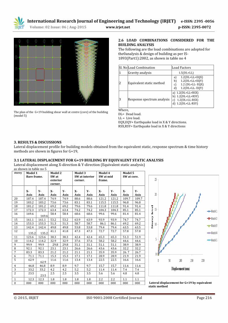
The plan of the G+19 building shear wall at centre (core) of the building (model 5)
3. RESULTS & DISCUSSIONS
2.6 LOAD COMBINATIONS CONSIDERED FOR THE BUILDING ANALYSIS The following are the load combinations are adopted for the0analysis & design of building as per IS-1893(Part1):2002, as shown in table no 4 Sl. No Load Combination Load Factors
1 Gravity analysis 1.5(DL+LL)
2 Equivalent static method
a) 1.2(DL+LL+EQX) b) 1.2(DL+LL+EQY) c) 1.2 (DL+LL- EQX) d) 1.2(DL+LL- EQY)
3 Response spectrum analysis
a) 1.2(DL+LL+RSX) b) 1.2(DL+LL+RSY) c) 1.2(DL+LL-RSX) d) 1.2(DL+LL-RSY)
Where, DL= Dead load. LL = Live load. EQX,EQY= Earthquake load in X & Y directions. RSX,RSY= Earthquake load in X & Y directions
Lateral displacement profile for building models obtained from the equivalent static, response spectrum & time history methods are shown in figures for G+19, 3.1 LATERAL DISPLACEMENT FOR G+19 BUILDING BY EQUIVALENT STATIC ANALYSIS Lateral displacement along X-direction & Y-direction (Equivalent static analysis) as shown in table no 5
Lateral displacement for G+19 by equivalent static method
storey Model 1 Bare frame.
Model 2 SW at exterior corner.
Model 3 SW at interior corner.
Model 4 SW at mid frame.
Model 5 SW at core.
X-Axis
Y-Axis
X-Axis
Y-Axis
X-Axis
Y-Axis
X-Axis
Y-Axis
X-Axis
Y-Axis
20 187.4 187.4 74.9 74.9 88.6 88.6 121.2 121.2 109.7 109.7 19 183.2 183.2 73.6 73.6 83.1 83.1 115.5 115.5 96.8 96.8 18 181.2 181.2 69.2 69.2 79.6 79.6 111.8 111.8 91.4 91.4 17 172.3 172.3 63.4 63.4 74.2 74.2 104.3 104.3 85.1 85.1 16 169.6
169.6
58.4 58.4 68.6 68.6 99.6 99.6 81.4 81.4
15 161.1 161.1 53.2 53.2 63.9 63.9 93.9 93.9 74.7 74.7 14 153.3 153.3 51.3 51.3 58.7 58.7 86.1 86.1 69.2 69.2 13 142.4 142.4 49.8 49.8 53.8 53.8 79.4 79.4 63.5 63.5 12
135.2
135.2
41.1 41.8 47.3 47.3 72.7 72.7 57.8 57.8
11 123.6 123.6 38.3 38.3 42.4 42.4 65.3 65.3 51.3 51.9 10 114.2 114.2 32.9 32.9 37.6 37.6 58.2 58.2 44.6 44.6 9 99.9 99.9 29.8 29.8 31.1 31.1 51.1 51.1 38.9 38.9 8 92.1 92.1 23.1 23.1 26.6 26.6 43.6 43.6 32.2 32.2 7 83.3 83.3 21.2 21.2 21.1 21.1 35.9 35.9 26. 7 26.7 6 71.1 71.1 15.3 15.3 17.1 17.1 28.9 28.9 21.9 21.9 5 62.9
62.9
11.6 11.6 13.4 13.4 22.5 22.5 16.6 16.6
4 46.8 46.8 8.9 8.9 9.7 9.7 15.7 15.7 11.6 11.6 3 33.2 33.2 4.2 4.2 5.2 5.2 11.4 11.4 7.4 7.4 2 23.5
23.5
2.5 2.5 3.5 3.5 5.6 5.6 4.8 4.8
1 12.3 12.3 1.8 1.8 1.8 1.8 2.2 2.2 1.1 1.1 0 000 000 000 000 000 000 000 000 000 000
International Research Journal of Engineering and Technology (IRJET) e-ISSN: 2395 -0056
Volume: 02 Issue: 06 | Aug-2015 www.irjet.net p-ISSN: 2395-0072
© 2015, IRJET ISO 9001:2008 Certified Journal Page 217
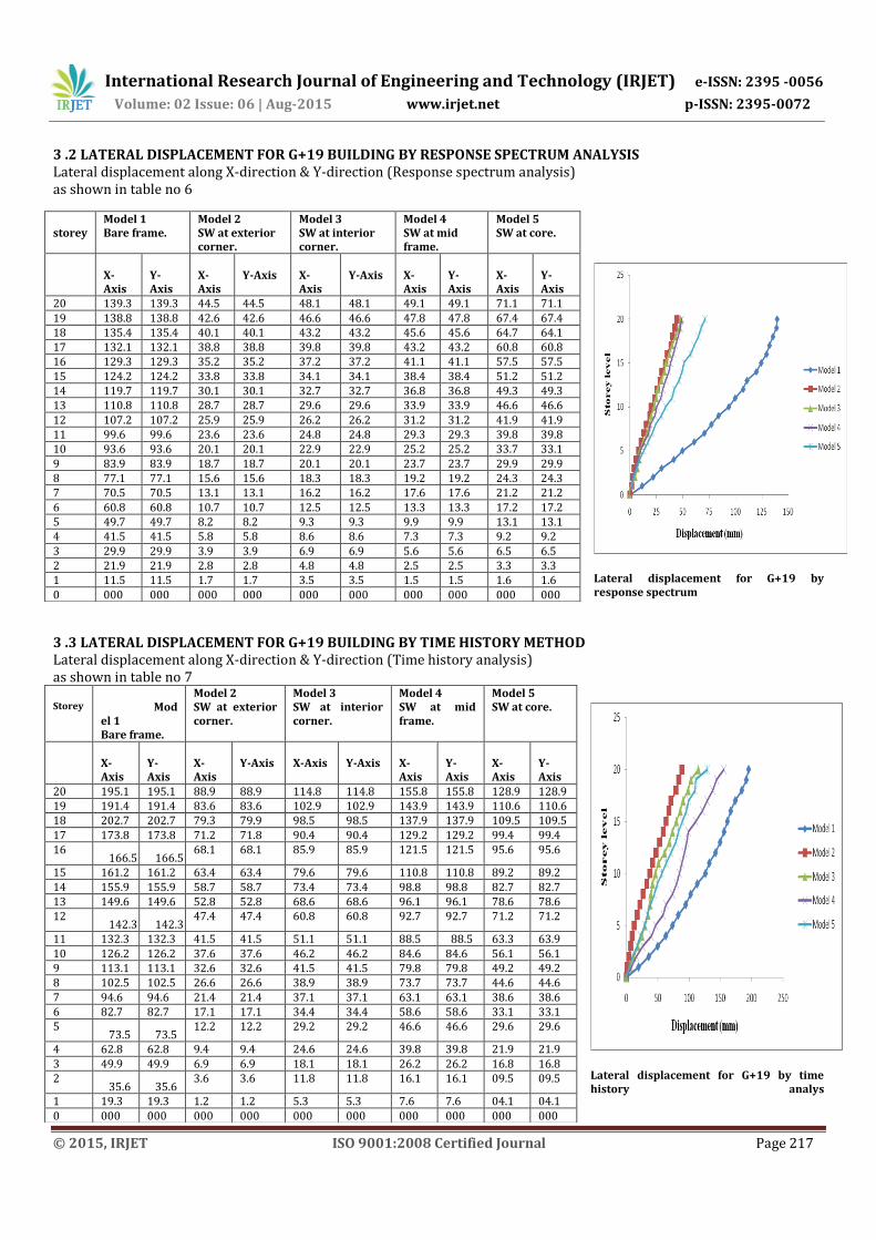
3 .2 LATERAL DISPLACEMENT FOR G+19 BUILDING BY RESPONSE SPECTRUM ANALYSIS Lateral displacement along X-direction & Y-direction (Response spectrum analysis) as shown in table no 6
Lateral displacement for G+19 by response spectrum
3 .3 LATERAL DISPLACEMENT FOR G+19 BUILDING BY TIME HISTORY METHOD Lateral displacement along X-direction & Y-direction (Time history analysis) as shown in table no 7
Lateral displacement for G+19 by time history analys
storey
Model 1 Bare frame.
Model 2 SW at exterior corner.
Model 3 SW at interior corner.
Model 4 SW at mid frame.
Model 5 SW at core.
X-Axis
Y-Axis
X-Axis
Y-Axis
X-Axis
Y-Axis
X-Axis
Y-Axis
X-Axis
Y-Axis
20 139.3 139.3 44.5 44.5 48.1 48.1 49.1 49.1 71.1 71.1 19 138.8 138.8 42.6 42.6 46.6 46.6 47.8 47.8 67.4 67.4 18 135.4 135.4 40.1 40.1 43.2 43.2 45.6 45.6 64.7 64.1 17 132.1 132.1 38.8 38.8 39.8 39.8 43.2 43.2 60.8 60.8 16 129.3 129.3 35.2 35.2 37.2 37.2 41.1 41.1 57.5 57.5 15 124.2 124.2 33.8 33.8 34.1 34.1 38.4 38.4 51.2 51.2 14 119.7 119.7 30.1 30.1 32.7 32.7 36.8 36.8 49.3 49.3 13 110.8 110.8 28.7 28.7 29.6 29.6 33.9 33.9 46.6 46.6 12 107.2 107.2 25.9 25.9 26.2 26.2 31.2 31.2 41.9 41.9 11 99.6 99.6 23.6 23.6 24.8 24.8 29.3 29.3 39.8 39.8 10 93.6 93.6 20.1 20.1 22.9 22.9 25.2 25.2 33.7 33.1 9 83.9 83.9 18.7 18.7 20.1 20.1 23.7 23.7 29.9 29.9 8 77.1 77.1 15.6 15.6 18.3 18.3 19.2 19.2 24.3 24.3 7 70.5 70.5 13.1 13.1 16.2 16.2 17.6 17.6 21.2 21.2 6 60.8 60.8 10.7 10.7 12.5 12.5 13.3 13.3 17.2 17.2 5 49.7 49.7 8.2 8.2 9.3 9.3 9.9 9.9 13.1 13.1 4 41.5 41.5 5.8 5.8 8.6 8.6 7.3 7.3 9.2 9.2 3 29.9 29.9 3.9 3.9 6.9 6.9 5.6 5.6 6.5 6.5 2 21.9 21.9 2.8 2.8 4.8 4.8 2.5 2.5 3.3 3.3 1 11.5 11.5 1.7 1.7 3.5 3.5 1.5 1.5 1.6 1.6 0 000 000 000 000 000 000 000 000 000 000
Storey
Model 1 Bare frame.
Model 2 SW at exterior corner.
Model 3 SW at interior corner.
Model 4 SW at mid frame.
Model 5 SW at core.
X-Axis
Y-Axis
X-Axis
Y-Axis
X-Axis
Y-Axis
X-Axis
Y-Axis
X-Axis
Y-Axis
20 195.1 195.1 88.9 88.9 114.8 114.8 155.8 155.8 128.9 128.9 19 191.4 191.4 83.6 83.6 102.9 102.9 143.9 143.9 110.6 110.6 18 202.7 202.7 79.3 79.9 98.5 98.5 137.9 137.9 109.5 109.5 17 173.8 173.8 71.2 71.8 90.4 90.4 129.2 129.2 99.4 99.4 16
166.5
166.5
68.1 68.1 85.9 85.9 121.5 121.5 95.6 95.6
15 161.2 161.2 63.4 63.4 79.6 79.6 110.8 110.8 89.2 89.2 14 155.9 155.9 58.7 58.7 73.4 73.4 98.8 98.8 82.7 82.7 13 149.6 149.6 52.8 52.8 68.6 68.6 96.1 96.1 78.6 78.6 12
142.3
142.3
47.4 47.4 60.8 60.8 92.7 92.7 71.2 71.2
11 132.3 132.3 41.5 41.5 51.1 51.1 88.5 88.5 63.3 63.9 10 126.2 126.2 37.6 37.6 46.2 46.2 84.6 84.6 56.1 56.1 9 113.1 113.1 32.6 32.6 41.5 41.5 79.8 79.8 49.2 49.2 8 102.5 102.5 26.6 26.6 38.9 38.9 73.7 73.7 44.6 44.6 7 94.6 94.6 21.4 21.4 37.1 37.1 63.1 63.1 38.6 38.6 6 82.7 82.7 17.1 17.1 34.4 34.4 58.6 58.6 33.1 33.1 5
73.5
73.5
12.2 12.2 29.2 29.2 46.6 46.6 29.6 29.6
4 62.8 62.8 9.4 9.4 24.6 24.6 39.8 39.8 21.9 21.9 3 49.9 49.9 6.9 6.9 18.1 18.1 26.2 26.2 16.8 16.8 2
35.6
35.6
3.6 3.6 11.8 11.8 16.1 16.1 09.5 09.5
1 19.3 19.3 1.2 1.2 5.3 5.3 7.6 7.6 04.1 04.1 0 000 000 000 000 000 000 000 000 000 000
International Research Journal of Engineering and Technology (IRJET) e-ISSN: 2395 -0056
Volume: 02 Issue: 06 | Aug-2015 www.irjet.net p-ISSN: 2395-0072
© 2015, IRJET ISO 9001:2008 Certified Journal Page 218
3.4 SUMMARY It can be noted that for equivalent static, response spectrum and time history analysis the lateral displacement is more predominant in bare frame (model 1), less and slightly more when the shear wall is located at exterior and interior corner of the building (model 2 and model 3) respectively when compared to building in which shear wall is located at mid frame (model 4) and at core (model 5). And as the level of the storey increased the lateral displacement also goes on increases. 3.5 CALCULATION OF BASESHEAR Base shear and scaling factor for 20 storied building model as shown in table 8 Longitudinal direction and transverse direction Baseshear (KN)
Model 1 Bare frame
Model 2 SW at exterior corner.
Model 3 SW at interior corner.
Model 4 SW at mid frame.
Model 5 SW at core.
VB 2530.8 3026.19 2800.61 2673.16 2907.69
Vb 1907.2 2804.68 2057.27 1789.63 2610.23
Scaling factor
1.3269 1.0789 1.3613 1.4936 1.113
The base shear value of the building in case of
equivalent static method and response spectrum method for different models of 20 storied building are given in table 8. In the response spectrum method the design base shear (VB) is made equal to the base shear obtained from equivalent static method (Vb) as perIS : 1893-2002 (Part 1) by applying the scaling factors calculated as shown in table 8
4. CONCLUSIONS The linear static analysis and dynamic analysis Response Spectrum Analysis& time history analysis have been completed to focus the suitable position of shear wall in the building and the outcomes have been looked at. The analysis has been completed on G+19 structures for different locations of shear walls. The following specific conclusions are drawn from the present work. The seismic analysis of R C frame structure is
finished by both static and dynamic analysis to focus and think about the base shear. It has been found that most extreme base shear in building with shear walls at exterior corner when contrasted with alternate models.
The presence of shear wall can influence the seismic conduct of frame structure to extensive
degree, and the shear wall increases the strength and stiffness of the structure. It has been found that the building with shear wall at exterior corner shows better location of shear wall since lateral displacement and base shear are compared with different models.
The results from static and dynamic analysis exhibit the typical expected behavior for building with shear walls at different locations.
In equivalent static analysis it has been found that model-2 shows lesser displacement when contrasted with different models in longitudinal and transverse direction when contrasted with alternate models. In response spectrum analysis model-2 shows lesser displacement when contrasted with other models in longitudinal and transverse direction when contrasted with alternate models.
REFERENCES
1. Agarwal, P. and Shrikhande, M.(2006), “Earthquake Design of Structures” Prentice Hall of India Private Limited New Delhi India.
2. Anshuman.S, D.Bhunia and R.Bhavin(2011) International Journal of Civil and Structural Engineering, Vol 2, Pilani, Rajastan, India.
3. AnujChandiwala,(2012)―Earthquake Analysis of Building Configuration with Different Position of Shear Wall‖, International Journal of Emerging Technology andAdvanced Engineering ISSN 2250-2459, ISO 9001:2008 Certified Journal, Volume 2, Issue 12, December 2012.
4. H.-S. Kim, D.-G.Lee(2008)―Analysis of shear wall with openings using super elements Engineering Structures 25 (2003) 981–991 [4]. M. Shariq, H. Abbas, H. Irtaza, M.Qamaruddin ―Influence of openings on seismic performance of masonry building walls‖Building and Environment 43 (2008) 1232–1240.
5. G.S Hiremath and Saddam Husain(2012)-Effect of Change in Shear Wall Location withUniform and Varying Thickness in High RiseBuilding.
6. IS 456:2000, “Code of Practice for Plain and Reinforced Concrete”, Bureau of Indian Standards, New Delhi, India.
7. IS 1893 (Part 1): (2002),“Criteria for Earthquake Resistant Design of Structures”, Bureau of Indian Standards, New Delhi 110002.
8. KasliwalSagar K. and AnantwadShirish,(2009) ―Effects of number and position of shear walls on seismic behavior of multi-storey structure‖ ISSN: 2278-7844, University ofPune.
International Research Journal of Engineering and Technology (IRJET) e-ISSN: 2395 -0056
Volume: 02 Issue: 06 | Aug-2015 www.irjet.net p-ISSN: 2395-0072
© 2015, IRJET ISO 9001:2008 Certified Journal Page 219
9. Murthy, C.V.R. (2002), “What is the Seismic Design Philosophy for Buildings?” Earthquake tip 08, IITK –BMTPC.
10. M.Ashrafaliand RavikanthChittiprolu(2008),-Significance of Shear Wall in Highrise Irregular Buildings
11. P. Chandurkar, Dr. P. Pajgade(2013) “Seismic analysis of RCC Buildings with and without shear wall” – International journal of modern engineering Research, Volume 3, PP-1805-1810.
BIOGRAPHIES
Sachin P Dyavappanavar (M.Tech Sacholar) Department of studies in Civil Engineering University BDT college of Engineering, Karnataka, India
Dr.K.Manjunath (BE.MSc.Ph.D.MIGS,MISTE,MISRMTT) Chairman & Professor Department of studies in Civil Engineering University BDT College of Engineering, Karnataka, India
Kavya N (M.Tech Scholar)
Department of studies in Civil Engineering
University BDT College of Engineering, Karnataka, India


![SHEAR WALLS FOR HIGH RISE BUILDINGS [].ppt](https://img.pdfslide.us/doc/110x75/55cf8531550346484b8bb1be/shear-walls-for-high-rise-buildings-wwwebmfilescomppt.jpg)