Embed Size (px)
Citation preview
NONLINEAR BEHAVIOUR OF COUPLED SHEAR WALLS STRENGTHENED WITH EXTERNALLY
BONDED CARBON FIBRE REINFORCED POLYMER COMPOSITE UNDER SEISMIC LOADINGS
by
Sara HONARPARAST
MANUSCRIPT-BASED THESIS PRESENTED TO ÉCOLE DE TECHNOLOGIE SUPÉRIEURE IN PARTIAL FULFILLMENT FOR THE
DEGREE OF DOCTOR OF PHILOSOPHY Ph.D.
MONTREAL, NOVEMBER 21, 2018
ÉCOLE DE TECHNOLOGIE SUPÉRIEURE UNIVERSITÉ DU QUÉBEC
© Copyright 2018 reserved by Sara Honarparast

© Copyright reserved
It is forbidden to reproduce, save or share the content of this document either in whole or in parts. The reader
who wishes to print or save this document on any media must first get the permission of the author.
BOARD OF EXAMINERS
THIS THESIS HAS BEEN EVALUATED
BY THE FOLLOWING BOARD OF EXAMINERS Mr. Omar Chaallal, Thesis Supervisor Department of Construction Engineering at École de technologie supérieure Mr. Anh Dung Ngô, President of the Board of Examiners Department of Mechanical Engineering at École de technologie supérieure Mr. Amar Khaled, Member of the jury Department of Construction Engineering at École de technologie supérieure Mr. Radhouane Masmoudi, External Evaluator Department of Civil Engineering, Université de Sherbrooke
THIS THESIS WAS PRESENTED AND DEFENDED
IN THE PRESENCE OF A BOARD OF EXAMINERS AND PUBLIC
ON 12 NOVEMBER, 2018
AT ÉCOLE DE TECHNOLOGIE SUPÉRIEURE


ACKNOWLEDGMENTS
Firstly, I would like to express my deepest appreciation to my supervisor Prof. Omar Chaallal
for his continuous support during my Ph.D study, for his patience, motivation, and immense
knowledge. His guidance helped me during my research period as well as writing of this
thesis. I am extremely grateful for his valuable support and friendship at academic and
personal levels.
I also would like to offer my special thanks to the members of my Ph.D. committee who
evaluated my thesis and provided valuable feedback.
The efficient collaboration of the technicians, Mr. John Lescelleur, Mr. Andres Barco, and
the application engineer, Mr. Richard Prowt, in conducting the experimental tests at ÉTS
structural laboratory is gratefully acknowledged.
Furthermore, I would like to thank Dr. Georges El-Saikaly for his help in performing the
experimental tests.
I am also grateful to my friends in Canada for their support and friendship.
Last but not the least, my sincere thanks also go to my family, especially my beloved parents
for their endless love and support in all stages of my life.

Comportement non linéaire sous charges sismiques de murs de refend couplés renforcés à l'aide de composite en polymeres renforcés de fibres de carbone collés en surface
Sara HONARPARAST
RÉSUMÉ
L’efficacité des murs de refend couplés (MRC) en béton armé (BA), comme système pour résister aux forces latérales dues aux vents et aux séismes, est bien établie. Les MRC sont généralement utilisés pour les bâtiments multi-étages de moyenne à grande hauteur. Ils résistent aux forces latérales grâce à la conjonction de la résistance au cisaillement et à la flexion de leurs segments de mur d’une part, et d’autre part à l'action des forces de cisaillement de leurs poutres de couplage. En effet, les forces de cisaillement générées par les poutres de couplage sont transférées aux murs sous forme de forces axiales de compression-traction générant ainsi un moment de flexion résistant au moment de renversement. Un MRC adéquatement conçu et détaillé devrait garantir que: (i) les poutres de couplage atteignent leur limite élastique (plastification) avant les murs; (ii) les poutres de couplage ne présentent pas de dégradation de résistance ou de rigidité sévère sous charges cycliques; et (iii) les poutres de couplage sont les éléments principaux de dissipation d'énergie en fournissant des boucles d'hystérésis stables et sans pincements. Cependant, concevoir et détailler des poutres de couplage offrant toutes ces propriétés importantes n'étaient pas possibles avant les années 1970. Aussi, les MRC construits avant 1970 risquent d’être sévèrement endommagés dans le cas d’un séisme modéré à sévère. De nombreuses techniques conventionnelles ont été utilisées avec plus ou moins de succès pour mettre à niveau et renforcer les structures déficientes et améliorer ainsi leur performance sismique. Au cours des dernières années, l'utilisation de matériaux composites à base de polymères renforcés de fibres (PRF) collés en surface s'est révélée être une méthode novatrice, efficace et économiquement viable pour la mise en état des structures en BA existantes. Cette thèse présente les résultats d'une étude expérimentale et des simulations numériques sur le comportement sismique, l'évaluation et la mise à niveau de MRC en BA existants conçus selon les codes et les normes d’avant les années 1970. Dans la partie expérimentale de cette étude, une méthode novatrice de renforcement externe utilisant un tissu de PRF de carbone (PRFC) a été proposée pour améliorer les performances sismiques des poutres de couplage en BA déficientes. À cette fin, deux échantillons de MRC avec une poutre de couplage en béton armé conventionnelle, représentatifs des MRC conçus selon les codes canadiens d’avant les années 1970, ont été considérés comme suit: Le premier a été utilisé comme spécimen de référence alors que le second a été renforcé avec du composite en PRFC collé en surface. Les deux spécimens ont été testés sous charge cyclique inversée pour évaluer l'efficacité de la méthode de renforcement proposée. De plus, un autre spécimen a été conçu en conformité à la norme de conception canadienne moderne en vigueur, c’est à dire avec poutre de couplage avec armatures diagonales. Ce spécimen a été soumis à un chargement cyclique jusqu'à un certain endommagement simulant un séisme. Par la suite, le spécimen endommagé a été réparé à l'aide de tissus en
VIII
PRFC collés en surface et de nouveau testé sous une charge cyclique inversée afin d’évaluer l'efficacité de la technique de réparation proposée. Les résultats expérimentaux ont révélé l’efficacité du système de renforcement en PRFC quant à l’amélioration de la résistance, la ductilité et la capacité de dissipation d'énergie de la poutre de couplage conçue selon la norme d’avant 1970 avec armature conventionnelle. Par ailleurs, ils ont également montré que la méthode de réparation proposée sur la poutre de couplage avec armature diagonale mais endommagée par un séisme, permet de recouvrer les propriétés initiales avant endommagement et notamment la résistance, la rigidité, la ductilité et la capacité de dissipation d'énergie. Les simulations numériques de cette étude ont porté sur l’analyse non linéaire temporelle d’un prototype de bâtiment de 20 étages situé au Canada, contreventé à l’aide de MRC. Quatre modèles de MRC dont deux modèles identiques sont conçus selon le Code national du bâtiment du Canada (CNBC) d’avant les années 1970 et les deux autres modèles sont conçus conformément au nouveau code de conception (CNBC 2015) et à la nouvelle norme (CSA A23.3-14) pour Montréal et Vancouver, représentatives de l'est et de l'ouest du Canada, respectivement. Des analyses dynamiques non linéaires utilisant le logiciel RUAUMOKO ont été réalisées sous accélérations sismiques étalonnées afin d'étudier le comportement structural des MRC, l'efficacité des normes modernes en vigueur et les déficiences des MRC conçus selon les normes d’avant 1970. Une méthode de renforcement à l’aide de composites en PRFC collés en surface a été proposée pour les structures de MRC déficientes, conformément au nouveau code de conception sismique. Les effets de cette méthode de renforcement sur l'amélioration du comportement sismique de ces MRC ont été étudiés par des analyses non linéaires temporelles. Les résultats de cette étude numérique ont révélé l’efficacité de la technique de renforcement à l’aide de PRFC puisqu’elle a permis d’améliorer la séquence de plastification, c’est-à-dire dans les poutres avant les murs, de réduire le déplacement latéral et inter-étage, et enfin de réduire la rotation des poutres de couplage et la demande en ductilité. L’étude a également révélé que, contrairement à l'ancien CNBC d’avant 1970, les exigences prescrites dans les normes CSA A23.3-14 et CNBC 2015 pour la conception en capacité des MRC ductiles sont satisfaisantes et se rapprochent des demandes sismiques. Mots clés: murs de refend couplés, poutre de couplage, renforcement, composite en PRFC,
collé en surface, performance sismique, essai de chargement cyclique, analyse sismique temporelle non linéaire
Nonlinear Behaviour of Coupled Shear Walls Strengthened with Externally Bonded Carbon Fibre Reinforced Polymer Composite under Seismic Loadings
Sara HONARPARAST
ABSTRACT
Reinforced concrete (RC) coupled shear walls (CSWs) with adequate strength and stiffness can be an effective system to resist lateral forces such as wind and earthquakes. CSWs are generally used for medium-high rise buildings. They resist lateral forces not only through the shear and moment resistance of their wall segments, but also through the shear action of their coupling beams (CBs). In CSWs, the shear forces are transferred through the CBs, and the overturning moment is partially resisted by an axial compression-tension that is coupled across the walls. A properly designed CSW should ensure that: (i) plastic hinging occurs in the CBs before it does in the walls; (ii) the CBs do not show major strength or stiffness degradations with load reversal; and (iii) the CBs should function as the primary energy-dissipation elements by providing stable energy-absorbing hysteresis loops without pinching. However, designing and detailing CBs with all these important features were not possible before the 1970s. Therefore, the old existing CSWs are potentially at risk of suffering severe damage under moderate to severe earthquakes. Many conventional techniques have been used with some success to retrofit and strengthen deficient structures and thereby improve their seismic performance. In the last few years, the use of externally bonded (EB) fiber reinforced polymer (FRP) composites has proven to be an innovative, reliable and a cost effective retrofit method for RC structures. This study presents results of an experimental and analytical investigation on the seismic behavior, evaluation, and retrofit of reinforced concrete CSWs designed according to codes and Standards before the 1970s. In the experimental part of this study, a new retrofit method using carbon FRP (CFRP) sheets was proposed to enhance the seismic performance of deficient reinforced concrete CBs. To that end, two coupled shear wall specimens with conventionally reinforced CB, representative of CSWs designed according to Canadian codes prior to the 1970s were considered as follows: One as a control specimen and the other strengthened using EB-CFRP. Both specimens were tested under reversed cyclic loading to assess the efficiency of the proposed retrofit method. In addition, one more specimen was designed according to modern Canadian design code and Standard with a diagonally reinforced CB. This specimen was submitted to cyclic loading up to failure simulating a seismic loading. Thereafter, the damaged specimen was repaired using EB-CFRP sheets and retested under reversed cyclic loading to investigate the effectiveness of the proposed repair technique. Experimental results revealed the ability of the CFRP retrofitting system to increase load carrying, ductility and energy dissipation capacity in deficient CB specimen designed according to old codes. In addition, the proposed repair method is also capable of recovering
X
the initial strength, stiffness, ductility and energy dissipation capacity in severely damaged CB specimen with diagonal reinforcement. The numerical part of this research study dealt with nonlinear time history analysis of a prototype 20-story coupled shear wall structure located in Canada. Four CSW prototype structures including two identical CSWs designed according to old National Building Code of Canada (NBCC) before 1970s, and two CSWs designed according to new design code (NBCC 2015) and Standard (CSA A23.3-14) located in Montreal and Vancouver as representative of East and West of Canada, respectively. Nonlinear dynamic analyses using RUAUMOKO were conducted under scaled earthquake accelerations to investigate the CSW structural behavior, adequacy of the design, and the deficiencies of old designed CSWs. An EB-CFRP retrofit method was proposed for deficient CSW structures to be in conformity with the new seismic design code. The beneficial effects of this retrofit method on seismic behavior of such CSWs was investigated through nonlinear time history analyses. The results of this analytical study revealed that the CFRP retrofitting technique performed very well since it resulted in improved sequence of yielding in CBs and walls, and reduced story displacement, inter-story drift, CBs rotation, and ductility demand. It was also found that unlike old NBCC, the requirements prescribed by CSA A23.3-14 and NBCC 2015 for the capacity design of ductile coupled walls are acceptable in approximating seismic demands. Keywords: coupled shear wall, coupling beam, strengthening, CFRP composite, externally
bonded, seismic performance, cyclic loading test, non-linear time history analysis
TABLE OF CONTENTS
Page
INTRODUCTION .....................................................................................................................1 0.1 General……………………………............…………………………………………...1 0.2 Problem statement……………………………………………………………………..2 0.3 Research objectives……………………………………………………………………4 0.4 Research methodology………………………………………………………………...4 0.5 Research significance………………………………………………………………….6 0.6 Organization of dissertation…………………………………………………………...7
CHAPTER 1 BACKGROUND AND LITERATURE REVIEW ........................................9 1.1 General definition of coupled shear walls .....................................................................9 1.2 Experimental studies on conventionally and diagonally reinforced CBs ....................10 1.3 Alternative designs of CBs ..........................................................................................14
1.3.1 Steel CBs and steel-concrete composite CBs ........................................... 14 1.3.2 Steel-fiber-reinforced concrete CB ........................................................... 19
1.4 Retrofitting methods of RC CSWs ..............................................................................20 1.4.1 Attaching steel plates to RC CBs .............................................................. 20 1.4.2 Adding new RC CBs ................................................................................. 22 1.4.3 Strengthening of CBs with fibre reinforced polymer ............................... 22
1.5 Non-linear analysis of CSWs .......................................................................................23 1.6 Previous studies on analysis of CSWs .........................................................................24
CHAPTER 2 SEISMIC UPGRADING OF RC COUPLED SHEAR WALLS : STATE OF THE ART AND RESEARCH NEEDS ..................................................29
2.1 Abstract ........................................................................................................................29 2.2 Introduction ..................................................................................................................29 2.3 Importance of CBs in coupled shear walls ..................................................................31 2.4 Deficiencies of existing CSWs ....................................................................................33
2.4.1 Evolution of seismic loading .................................................................... 33 2.4.2 Design evolution of CSWs........................................................................ 36
2.5 Diagonal reinforcement concept for CBs ....................................................................37 2.6 Failure modes of coupled shear walls ..........................................................................39
2.6.1 Flexural failure mode ................................................................................ 40 2.6.2 Shear failure mode .................................................................................... 40 2.6.3 Rigid action ............................................................................................... 41
2.7 Review of retrofit and upgrading methods for CSWs .................................................41 2.7.1 Application of steel plates to one side of shear-deficient reinforced
CBs ............................................................................................................ 42 2.7.2 Upgrading the degree of coupling of coupled shear walls ........................ 43 2.7.3 Attaching external steel plates to the side faces of CBs ........................... 44 2.7.4 Application of fiber-reinforced polymer sheet ......................................... 45
2.8 Review of alternative designs of CBs ..........................................................................47
XII
2.8.1 Steel CBs with and without stiffeners ....................................................... 47 2.8.2 Concrete-filled steel-tube CBs .................................................................. 47 2.8.3 Steel CBs encased in reinforced concrete members ................................. 48 2.8.4 Embedded steel-composite CB with shear studs ...................................... 49
2.9 Retrofit of beam-wall joints .........................................................................................49 2.10 Advantages and disadvantages of retrofit methods and perspectives for FRP
composites....................................................................................................................51 2.11 Required research .........................................................................................................53 2.12 Conclusions ..................................................................................................................54
CHAPTER 3 EXPERIMENTAL SEISMIC PERFORMANCE EVALUATION OF CBs: COMPARISON OF OLD WITH MODERN CODES ........................55
3.1 Abstract ........................................................................................................................55 3.2 Introduction ..................................................................................................................55 3.3 Experimental program .................................................................................................59
3.3.1 Test specimens .......................................................................................... 60 3.3.2 Material properties .................................................................................... 60 3.3.3 Instrumentation ......................................................................................... 62 3.3.4 Test setup and loading procedure ............................................................. 62
3.4 Test results and discussion ...........................................................................................64 3.4.1 Failure modes ............................................................................................ 64 3.4.2 Load-Displacement Hysteretic Curve ....................................................... 67 3.4.3 Displacement ductility .............................................................................. 68 3.4.4 Energy dissipation ..................................................................................... 70 3.4.5 Strength and stiffness degradation ............................................................ 71
3.5 Conclusions ..................................................................................................................72 3.6 Acknowledgement .......................................................................................................74
CHAPTER 4 EXTERNALLY BONDED CFRP COMPOSITES FOR SEISMIC RETROFIT OF RC CBS DESIGNED ACCORDING TO OLD CODES ...75
4.1 Abstract ........................................................................................................................75 4.2 Introduction ..................................................................................................................76 4.3 Experimental program .................................................................................................80
4.3.1 Test specimens .......................................................................................... 81 4.3.2 Material properties .................................................................................... 82 4.3.3 Strengthening procedures .......................................................................... 82 4.3.4 Instrumentation ......................................................................................... 84 4.3.5 Test setup and loading program ................................................................ 86
4.4 Test results and discussion ...........................................................................................87 4.4.1 Failure modes ............................................................................................ 87 4.4.2 Load-Displacement Hysteretic Curve ....................................................... 89 4.4.3 Ductility .................................................................................................... 89 4.4.4 Energy dissipation ..................................................................................... 91 4.4.5 Strength and stiffness degradation ............................................................ 92 4.4.6 Strain of external CFRP ............................................................................ 93
XIII
4.4.7 Contributions of the components to the shear resistance .......................... 94 4.5 CONCLUSIONS..........................................................................................................96
CHAPTER 5 SEISMIC RETROFIT OF PRE-DAMAGED DIAGONALLY RC CBS USING EXTERNALLY BONDED CFRP COMPOSITES ........................99
5.1 Abstract ........................................................................................................................99 5.2 Introduction ..................................................................................................................99 5.3 Experimental program ...............................................................................................102
5.3.1 Test specimen and instrumentation ......................................................... 103 5.3.2 Material properties .................................................................................. 104 5.3.3 Repairing procedures .............................................................................. 106 5.3.4 Test setup and loading program .............................................................. 107
5.4 Test results and discussions .......................................................................................109 5.4.1 Failure modes .......................................................................................... 109 5.4.2 Load-Displacement Hysteretic Curve ..................................................... 111 5.4.3 Ductility .................................................................................................. 112 5.4.4 Energy dissipation ................................................................................... 114 5.4.5 Strength and stiffness degradation .......................................................... 114 5.4.6 Strain in EB-CFRP strips ........................................................................ 116 5.4.7 Contributions of the components to the shear resistance ........................ 117
5.5 CONCLUSIONS........................................................................................................119
CHAPTER 6 NON-LINEAR TIME HISTORY ANALYSIS AND COMPARISON OF COUPLED SHEAR WALLS DESIGNED ACCORDING TO OLD AND MODERN CODES AND SEISMIC RETROFIT WITH EXTERNALLY BONDED CFRP COMPOSITES FOR EASTERN CANADA ...................................................................................................121
6.1 Abstract ......................................................................................................................121 6.2 Introduction ................................................................................................................122 6.3 Canadian seismic design provisions ..........................................................................126 6.4 CSA standard A23.3-14 provisions for the design of CSWs .....................................129 6.5 Description of studied building ..................................................................................130 6.6 Retrofit of deficient CSW1941 using EB-CFRP composite ......................................133 6.7 Non-linear time history analysis of CSWs .................................................................135
6.7.1 Inelastic structural models ...................................................................... 135 6.7.2 Selecting and scaling of earthquake ground motion histories ................ 138
6.8 Inelastic seismic analysis results ................................................................................140 6.8.1 Displacement and inter-story drift .......................................................... 140 6.8.2 Story shear of the wall piers .................................................................... 143 6.8.3 Flexural moment of wall piers ................................................................ 143 6.8.4 Beam rotations ........................................................................................ 145 6.8.5 Sequence of plastic hinge formation ....................................................... 146 6.8.6 Wall curvature ......................................................................................... 147
6.9 Conclusions ................................................................................................................148
XIV
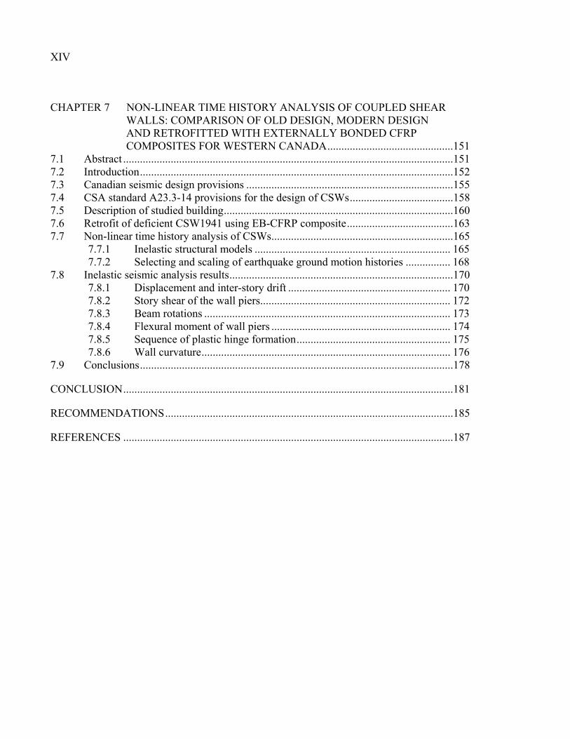
CHAPTER 7 NON-LINEAR TIME HISTORY ANALYSIS OF COUPLED SHEAR WALLS: COMPARISON OF OLD DESIGN, MODERN DESIGN AND RETROFITTED WITH EXTERNALLY BONDED CFRP COMPOSITES FOR WESTERN CANADA .............................................151
7.1 Abstract ......................................................................................................................151 7.2 Introduction ................................................................................................................152 7.3 Canadian seismic design provisions ..........................................................................155 7.4 CSA standard A23.3-14 provisions for the design of CSWs .....................................158 7.5 Description of studied building ..................................................................................160 7.6 Retrofit of deficient CSW1941 using EB-CFRP composite ......................................163 7.7 Non-linear time history analysis of CSWs .................................................................165
7.7.1 Inelastic structural models ...................................................................... 165 7.7.2 Selecting and scaling of earthquake ground motion histories ................ 168
7.8 Inelastic seismic analysis results ................................................................................170 7.8.1 Displacement and inter-story drift .......................................................... 170 7.8.2 Story shear of the wall piers .................................................................... 172 7.8.3 Beam rotations ........................................................................................ 173 7.8.4 Flexural moment of wall piers ................................................................ 174 7.8.5 Sequence of plastic hinge formation ....................................................... 175 7.8.6 Wall curvature ......................................................................................... 176
7.9 Conclusions ................................................................................................................178
CONCLUSION ......................................................................................................................181
RECOMMENDATIONS .......................................................................................................185
REFERENCES ......................................................................................................................187
LIST OF TABLES
Page
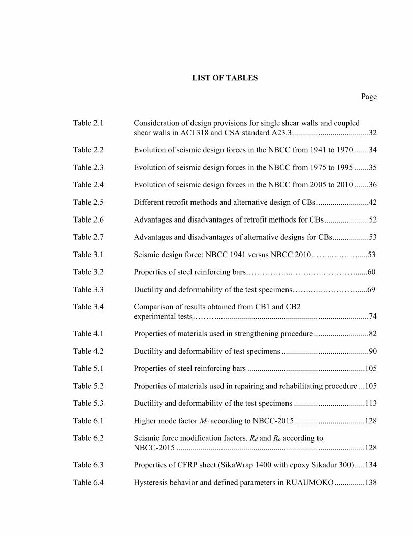
Table 2.1 Consideration of design provisions for single shear walls and coupled shear walls in ACI 318 and CSA standard A23.3 ......................................32
Table 2.2 Evolution of seismic design forces in the NBCC from 1941 to 1970 .......34
Table 2.3 Evolution of seismic design forces in the NBCC from 1975 to 1995 .......35
Table 2.4 Evolution of seismic design forces in the NBCC from 2005 to 2010 .......36
Table 2.5 Different retrofit methods and alternative design of CBs ..........................42
Table 2.6 Advantages and disadvantages of retrofit methods for CBs ......................52
Table 2.7 Advantages and disadvantages of alternative designs for CBs ..................53
Table 3.1 Seismic design force: NBCC 1941 versus NBCC 2010……..….…….....53
Table 3.2 Properties of steel reinforcing bars……………...…….…..…………......60
Table 3.3 Ductility and deformability of the test specimens…….…..…………......69
Table 3.4 Comparison of results obtained from CB1 and CB2 experimental tests………...........................................................................74
Table 4.1 Properties of materials used in strengthening procedure ...........................82
Table 4.2 Ductility and deformability of test specimens ...........................................90
Table 5.1 Properties of steel reinforcing bars ..........................................................105
Table 5.2 Properties of materials used in repairing and rehabilitating procedure ...105
Table 5.3 Ductility and deformability of the test specimens ...................................113
Table 6.1 Higher mode factor Mv according to NBCC-2015 ...................................128
Table 6.2 Seismic force modification factors, Rd and Ro according to NBCC-2015 .............................................................................................128
Table 6.3 Properties of CFRP sheet (SikaWrap 1400 with epoxy Sikadur 300) .....134
Table 6.4 Hysteresis behavior and defined parameters in RUAUMOKO ...............138
XVI
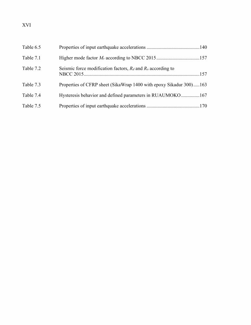
Table 6.5 Properties of input earthquake accelerations ...........................................140
Table 7.1 Higher mode factor Mv according to NBCC 2015 ...................................157
Table 7.2 Seismic force modification factors, Rd and Ro according to NBCC 2015 ..............................................................................................157
Table 7.3 Properties of CFRP sheet (SikaWrap 1400 with epoxy Sikadur 300) .....163
Table 7.4 Hysteresis behavior and defined parameters in RUAUMOKO ...............167
Table 7.5 Properties of input earthquake accelerations ...........................................170
LIST OF FIGURES
Page
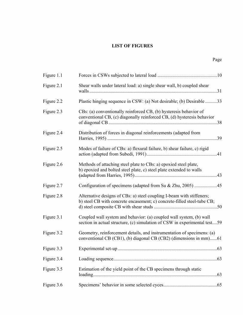
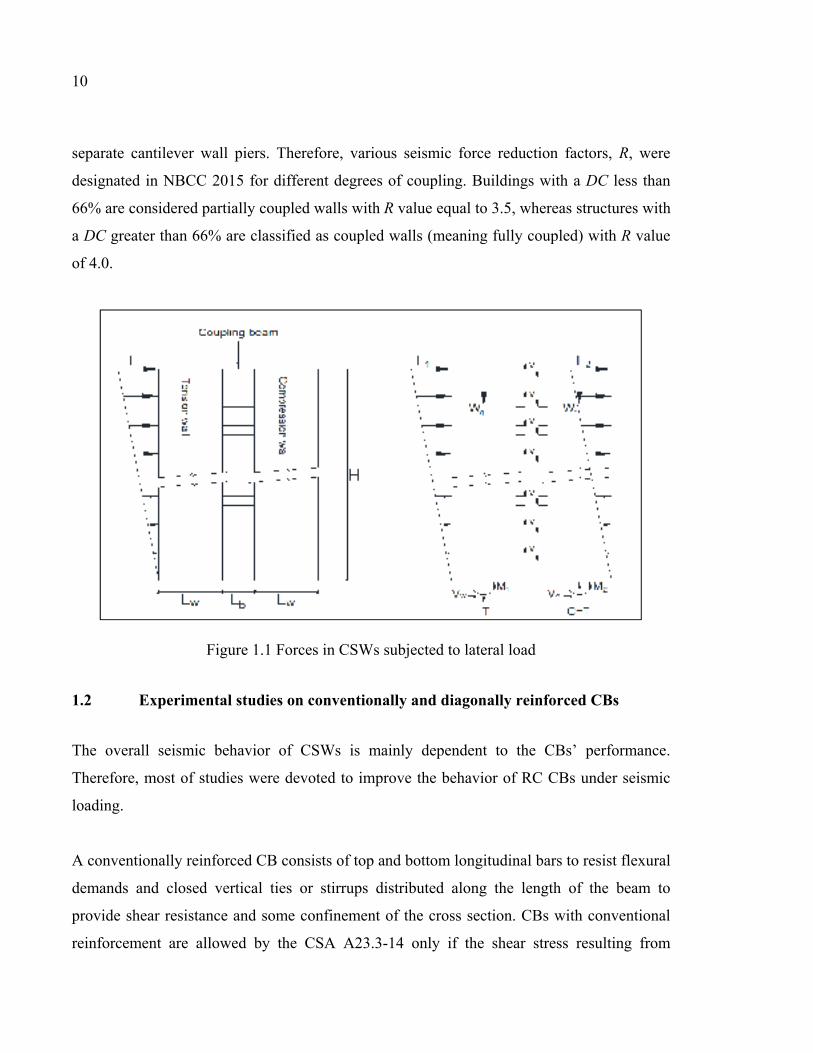
Figure 1.1 Forces in CSWs subjected to lateral load ..................................................10
Figure 2.1 Shear walls under lateral load: a) single shear wall, b) coupled shear walls ...........................................................................................................31
Figure 2.2 Plastic hinging sequence in CSW: (a) Not desirable; (b) Desirable ..........33
Figure 2.3 CBs: (a) conventionally reinforced CB, (b) hysteresis behavior of conventional CB, (c) diagonally reinforced CB, (d) hysteresis behavior of diagonal CB ...........................................................................................38
Figure 2.4 Distribution of forces in diagonal reinforcements (adapted from Harries, 1995) ............................................................................................39
Figure 2.5 Modes of failure of CBs: a) flexural failure, b) shear failure, c) rigid action (adapted from Subedi, 1991) ...........................................................41
Figure 2.6 Methods of attaching steel plate to CBs: a) epoxied steel plate, b) epoxied and bolted steel plate, c) steel plate extended to walls (adapted from Harries, 1995) .....................................................................43
Figure 2.7 Configuration of specimens (adapted from Su & Zhu, 2005) ...................45
Figure 2.8 Alternative designs of CBs: a) steel coupling I-beam with stiffeners; b) steel CB with concrete encasement; c) concrete-filled steel-tube CB; d) steel composite CB with shear studs .....................................................50
Figure 3.1 Coupled wall system and behavior: (a) coupled wall system, (b) wall section in actual structure, (c) simulation of CSW in experimental test ....59
Figure 3.2 Geometry, reinforcement details, and instrumentation of specimens: (a) conventional CB (CB1), (b) diagonal CB (CB2) (dimensions in mm) ......61
Figure 3.3 Experimental set-up ...................................................................................63
Figure 3.4 Loading sequence .......................................................................................63
Figure 3.5 Estimation of the yield point of the CB specimens through static loading........................................................................................................63
Figure 3.6 Specimens’ behavior in some selected cyces .............................................65
XVIII
Figure 3.7 Hysteretic behavior of specimens ..............................................................68
Figure 3.8 Ductility factor: (a) Method of computing ductility factor, (b) Ductility of specimens during each loading cycle ...............................69
Figure 3.9 Envelope of hysteretic loops of specimen CB1, CB2 ................................70
Figure 3.10 Cumulative dissipated energy per cycle for specimens (a) CB1, (b) CB2.......................................................................................................71
Figure 3.11 Strength and stiffness degradation of specimens CB1, CB2: a) Strength degradation, b) Stiffness degradation ......................................72
Figure 4.1 Response of CSW to lateral loading: (a) actual structure, (b) experimental test setup .........................................................................81
Figure 4.2 Geometry and reinforcement details of conventionally reinforced CB .....81
Figure 4.3 Strengthening procedure for the CB specimen: (1) Impregnation of fibers with Sikadur 300, (2) Coating the concrete surface with Sikadur 330, (3) Bonding the first strip of CFRP onto one diagonal, (4) Bonding the second strip of CFRP to another diagonal .......................85
Figure 4.4 Strain gauges installed onto steel reinforcements and CFRP strips: a) CB.CONV, b) CB.CONV-R ..................................................................85
Figure 4.5 Experimental setup.....................................................................................86
Figure 4.6 Loading sequence .......................................................................................87
Figure 4.7 Crack pattern of specimens at failure: (a) CB.CONV, (b) CB.CONV-R ........................................................................................88
Figure 4.8 Hysteretic behavior of specimens ..............................................................89
Figure 4.9 Envelopes of hysteretic loops of specimens CB.CONV and CB.CONV-R ..............................................................................................91
Figure 4.10 Energy dissipation of specimens CB.CONV and CB.CONV-R ................91
Figure 4.11 Strength degradation of specimens ............................................................92
Figure 4.12 Stiffness degradation of specimens ............................................................93
Figure 4.13 Strain of CFRP along the CSW .................................................................94
Figure 4.14 Component shear contributions of specimens: (a) CB.CONV (b) CB.CONV-R ........................................................................................96
XIX
Figure 5.1 Response of CSW to lateral loading: (a) actual structure, (b) experimental test setup .......................................................................102
Figure 5.2 Geometry, reinforcement details, CFRP configuration, and instrumentation : (a) original coupling specimen, (b) rehabilitated specimen using CFRP strips, (dimension in mm) ....................................104
Figure 5.3 Repair and rehabilitation procedures of CB specimen: (a) repair, (b) rehabilitation ............................................................................................108
Figure 5.4 Experimental setup...................................................................................109
Figure 5.5 Crack pattern of specimens at failure: (a) CB.DIAG, (b) CB.DIAG-R... 110
Figure 5.6 Hysteretic behavior of specimens ............................................................111
Figure 5.7 Envelopes of hysteretic loops of specimens CB.DIAG and CB.DIAG-R .............................................................................................112
Figure 5.8 Ductility factor: (a) Method of computing ductility factor, (b) Ductility of specimens during each loading cycle .............................113
Figure 5.9 (a) Comparison of energy dissipation capacity of specimens, (b) dissipated energy per cycle in CB.DIAG, (c) dissipated energy per cycle CB.DIAG-R ..............................................................................115
Figure 5.10 Degradation of specimens CB.CONV and CB.CONV-R: a) strength degradation, b) stiffness degradation .......................................................116
Figure 5.11 Strains in EB-CFRP along the CSW ........................................................117
Figure 5.12 Component shear contributions of specimen CB.DIAG-R ......................118
Figure 6.1 Elevation and plan view of studied building ............................................132
Figure 6.2 Design summary of CSW1941: (a) Reinforcement details of conventionally reinforced CBs, (b) Reinforcement details of a wall .......132
Figure 6.3 Design summary of CSW2015: (a) Reinforcement details of conventionally reinforced CBs, (b) Reinforcement details of one wall ...133
Figure 6.4 Design summary of CFRP retrofitted CSW: (a) Retrofitted CBs, (b) Retrofitted wall ...................................................................................135
Figure 6.5 Types of elements in RUAUMOKO: (a) CBs model, (b) walls model ...137
XX
Figure 6.6 a) Determination of target spectrum, period range TR and scenario- specific period ranges TRS1 and TRS2; b) Acceleration spectra of the selected and scaled individual ground motion time histories; c) Mean acceleration spectra for scenarios 1 and 2; d) Difference between the mean Sg(T) of the scaled records and ST(T) within each scenario- specific period range ................................................................................141
Figure 6.7 (a) Mean of story displacement under all earthquake inputs; (b) Inter- story drift response envelopes ..................................................................142
Figure 6.8 Comparison of walls shear force ..............................................................144
Figure 6.9 Comparison of walls moment at each story level ....................................145
Figure 6.10 CBs rotation in CSW1941, CSW2015, and CFRP retrofitted CSW1941-R .............................................................................................146
Figure 6.11 Sequence of plastic hinge formation in CBs and at the base of the walls .........................................................................................................147
Figure 6.12 Wall curvature envelopes for CSW1941, CSW2015, and CSW1941-R .............................................................................................148
Figure 7.1 Elevation and plan view of studied building ............................................161
Figure 7.2 Design summary of CSW1941: (a) Reinforcement details of conventionally reinforced CBs, (b) Reinforcement details of a wall .......162
Figure 7.3 Design summary of CSW2015: (a) Reinforcement details of conventionally reinforced CBs, (b) Reinforcement details of one wall ...162
Figure 7.4 Design summary of CFRP retrofitted CSW: (a) Retrofitted CBs, (b) Retrofitted wall ........................................................................................164
Figure 7.5 Types of elements in RUAUMOKO: (a) CBs model, (b) walls model ...165
Figure 7.6 a) Determination of target spectrum, period range TR and TRS1 and TRS2; b) Acceleration spectra of the selected and scaled individual ground motion time histories; c) Mean acceleration spectra for scenarios 1 and 2; d) Difference between the mean Sg(T) of the scaled records and ST(T) within each scenario-specific period range ....................................169
Figure 7.7 (a) Mean of story displacement under all earthquake inputs; (b) Inter- story drift response envelopes ..................................................................171
Figure 7.8 Comparison of walls shear force ..............................................................173
XXI
Figure 7.9 CBs rotation in CSW1941, CSW2015, and CFRP retrofitted CSW1941-R .............................................................................................174
Figure 7.10 Comparison of walls moment at each story level ....................................175
Figure 7.11 Sequence of plastic hinge formation in CBs and at the base of the walls .........................................................................................................176
Figure 7.12 Wall curvature envelopes for CSW1941, CSW2015, and CSW1941-R .............................................................................................177

LIST OF ABREVIATIONS
ACI American Concrete Institute ASCE American Society of Civil Engineers ASTM American Society for Testing and Materials CB Coupling Beam CB.CONV Conventionally reinforced Coupling Beam CB.DIAG Diagonally reinforced Coupling Beam CFRP Carbon Fiber Reinforced Polymer CFRT Concrete-Filled Rectangular Tube CSA Canadian Standard Association CSW Coupled Shear Wall DC Degree of Coupling EB Externally Bonded FRP Fiber Reinforced Polymer HCW Hybrid Coupled Wall LVDT Linear Variable-Displacement Transducers NBCC National Building Code of Canada PRC Plate-reinforced concrete Composite RC Reinforced Concrete SFRC Steel-Fibre Reinforced Concrete SFRS Seismic Force Resisting System


LIST OF SYMBOLS
AI Axial rigidity Asd Area of steel bars in one diagonal group Av Area of the steel stirrups C Type of construction factor Ci Horizontal force factor d Beam depth DL Dead load DSL Design snow load dv Effective shear depth of the beam EFRP Modulus of elasticity of the FRP sheets EI Flexural rigidity Es modulus of elasticity of the steel reinforcing bars F Foundation factor fc΄ Compressive strength of concrete fu Ultimate tensile strength of steel reinforcing bars fy Yield strength of steel reinforcements h Story height hw Height of the wall I Importance factor Kα A measure of the relative stiffness of the coupling beams and walls lcg Horizontal distance between the centroids of walls in CSWs lb Beam length
XXVI
LL Live load lu Clear span of coupling beam lw Wall depth M External moment applied to the structure M1 Moment resisted by wall 1 M2 Moment resisted by wall 2 Mv Factor to account for the effect of higher modes N Axial force Ni Axial force related to the retrofitted CBs P Axial force resulting from coupling action Rd Ductility-related factor Ro Overstrength-related factor s Distance between the steel stirrups S Structural flexibility factor S(Ta) Design-spectral-response acceleration at the fundamental period SL Snow load Ta Fundamental period of vibration tFRP Thickness of FRP sheets V Shear Strength Vc Shear resistance of concrete VFRP Shear resistance FRP composites Vn Nominal shear strength Vp Peak shear force
XXVII
Vs Shear resistance of transverse steel reinforcement Vy Yield shear force W Weight of the building wFRP Width of the FRP strip x Rigid portion y Lateral deflection z Height above the base of the structure ∆p Displacement at peak load ∆u Ultimate displacement ∆y Yield displacement α Angle of diagonal bars and horizontal axis in coupling beam β Angle of FRP strips and horizontal axis εFRPe Effective strain of the FRP sheets εs Steel strain θu Ultimate rotation angle θy Yield rotation μd Displacement ductility ν(x) Shear force intensity φc Resistance factor for concrete φFRP Resistance factor for FRP φs Resistance factor for steel

INTRODUCTION
0.1 General
A large number of reinforced concrete (RC) structures were designed and constructed before
the development of modern building codes. The design of many of these old structures were
dominated by gravity load effects, resulting in construction details that are now recognized to
be associated with non-ductile failure modes under seismic loading. Numerous old existing
buildings contain reinforced concrete coupled shear walls (CSWs) as lateral load resisting
systems. The behavior of CSWs built prior to the 1970s, is assessed to be potentially critical
in the event of an earthquake. This is due to shortcomings of their coupling beams (CBs) and
their wall segments related to lack of little or no transverse reinforcement in the CBs and near
the wall ends, insufficient lap splices, poor anchorage of the transverse and longitudinal
reinforcement, lack of flexural reinforcement, and poor construction joints under seismic
loadings. Such deficiencies would lead to diagonal cracks in the CBs, yielding of the shear
reinforcement before failure, formation of deep flexural cracks at the beam–wall joints, and
sliding movement along the cracks at the beam–wall joints followed by brittle shear failure.
Therefore, appropriate measures such as replacement of the structure or seismic retrofit of
lateral resisting system should be taken to address these deficiencies.
In the past, several methods were used for strengthening or retrofitting RC structural
buildings. Increasing the gross section through adding new structural material to an already
existing structural element, posttensioning, replacing of some structural elements or changing
the structural system, attaching steel plates to a concrete surface are some of the conventional
techniques used in the past. Although these methods can be successful in some cases, they
are not always cost-effective in enhancing the seismic performance and are often not
sustainable.
2
During the last decades, Fibre-Reinforced Polymers (FRP) have received much attention for
a variety of applications related to strengthening of defective structures. The outstanding
mechanical properties of FRP combined with low weight, corrosion resistance and easy
application make the FRP composites a real and viable solution to retrofit deficient RC
structures. In spite of using FRP composites in different structural elements such as beams,
columns, bridges, and slabs, more research is needed to extend the application to retrofit
deficient RC CSWs.
This has been the main impetus to carry out the present research project, to investigate
experimentally and numerically the effectiveness of EB- FRP composites in upgrading the
seismic properties and response of CBs pertaining to old designed CSWs.
0.2 Problem statement
Many old existing RC buildings in developed countries and cities need to be strengthened
due to the introduction of new seismic design requirements in modern codes and standards,
rapid deterioration of reinforced concrete and poor original concrete quality. It is often more
economical to retrofit deficient structural components than to replace the entire buildings. RC
CSWs are widely used as a lateral load resisting system in medium to high-rise buildings to
resist seismic loading. In CSWs, the individual wall piers are coupled together by CBs to
increase the lateral strength and the stiffness of the buildings. The overturning moments are
thereby resisted by an axial compression-tension couple across the wall system rather than by
solely the individual flexural action of the walls. CBs in CSWs are an essential structural
component since they transfer shear forces from one wall to another. Therefore, the beams
must retain much of their ability to transfer load and to reduce the bending moment at the
base of the CSWs. Otherwise, the small amount of shear force is transferred between the
shear walls and due to the decrease of CBs’ load capacity, the wall piers act as two
independent cantilevers.
3
From the viewpoint of earthquake resistance, the use of ductile structural components for
dissipating energy to delay or prevent yielding of critical vertical elements is an important
design strategy. Therefore, to achieve the optimum performance of CSWs in dissipating
earthquake energy, plastic hinge formation in most of the CBs should occur prior to plastic
hinging at the base of each wall. This means that the CBs must yield first and walls are the
last to yield to maintain gravity load resistance of the structure and allow large deformation
before collapse.
In past decades, the design of many concrete buildings in Canada did not take into account
earthquake actions. Following the evolution of design codes, many existing CBs were found
to be deficient in shear capacity. The past earthquake records caused brittle shear failure in
many deep RC CBs accompanied with severe damage (Mitchell et al., 1995). This resulted in
significant decrease in the structural safety of the entire building. Due to structural
deficiencies, many of the existing CSWs are in need of strengthening and retrofit. As will be
presented in the next chapter, in order to enhance the seismic behavior of CSWs, alternative
design methods such as diagonally reinforced CBs, steel CBs, rectangular steel tube CBs
with concrete infill and embedded steel plate CBs were proposed. In spite of achieving some
improvements in the seismic performance of CSWs, they still have some drawbacks and fail
to address all the deficiencies. Therefore, further research is needed to develop suitable,
innovative, cost-effective and practical methods for strengthening existing CSWs and
particularly CBs. In recent years, considerable research has been carried out to investigate the
behaviour of EB-FRP used for strengthening and retrofitting concrete structures. As a result,
many codes and design guidelines have been published in this area. The use of FRP sheets to
strengthen RC structural elements such as slabs, beams and columns, is well documented.
However, this is not the case for CBs. Since the behavior of CBs is particular and different
from flexural beams, a special attention should be exercised to develop an effective retrofit
method for CBs. In this regard, the aim of this research project is to evaluate the probable
effectiveness of EB-carbon FRP (CFRP) composites for the seismic retrofit of CBs of CSWs
and to develop a comprehensive technique for practical applications.
4
0.3 Research objective
This research study is intended to contribute to the development of a strengthening method of
CSWs using EB-CFRP composites through experimental and numerical investigations.
The main objective of this research is to evaluate the feasibility of retrofitting old CSWs with
EB-CFRP to conform to new standards.
Specific objectives are as follows:
1. To determine, by experimental tests, the cyclic behaviour of as-built RC CBs designed
according to old (pre-1970s) and new standards;
2. To develop a suitable and realistic retrofit intervention to upgrade the as-built CBs with
EB CFRP composites;
3. To investigate the efficiency of the developed retrofit method through comparison of
seismic performance of strengthened CBs with original ones;
4. To conduct a numerical study to investigate the effectiveness of retrofit method by
comparing the seismic behavior of CSWs including old designed CSWs, modern
designed CSWs and CSWs strengthened with CFRP composites under earthquake
accelerations;
5. To assess the adequacy of new provisions specified in standards for design of ductile
CSWs through nonlinear time history analysis.
0.4 Research methodology
The methodology adopted to achieve the objectives outlined in the previous section include
experimental and numerical investigations.
The experimental investigation was conducted in the first part of this research as follows.
5
Two identical CSW specimens with conventionally reinforced CB were designed and
constructed according to old seismic design code, NBCC 1941. One of them was considered
as a control specimen and the other one was retrofitted using CFRP strips to conform to the
modern seismic design code. Both specimens were tested under reversed cyclic loading until
failure. Then, the results of experimental tests were compared to evaluate the efficiency of
retrofit method in enhancement of seismic behavior of old designed CBs.
Additionally, a RC CSW specimen designed according to the modern seismic design code
(NBCC 2015), and Canadian Standard (CSA A23.3-14) with a diagonally reinforced CB was
constructed and tested under reversed cyclic loading. Then, the failed specimen was repaired,
retrofitted with CFRP strips and retested under cyclic loading. This was carried out to study
the effect of CFRP retrofit method on the CBs which conform to the new Standards.
However, they would experience an undesirable performance due to several reasons such as
change of functionality, structural intervention (eg. new openings are created or bearing
elements are removed), design errors, construction faults or exceptional events.
The second part of this research study was dedicated to numerical investigations of CSWs as
explained in the following paragraghs.
Two types of 20-story reinforced concrete building in which the seismic force resisting
system (SFRS) is CSWs, was defined on soil type C. Two different locations, Montreal and
Vancouver, were selected as representatives of Eastern and Western seismic Canadian zones.
In the first, the modern CSW elements were designed and detailed according to NBCC 2015
and CSA A23.3-14 for the two selected locations, considering the SFRS as ductile. While in
the other type, the old existing CSWs designed according to the requirements of NBCC 1941
were considered. Since there was no specific seismic zone in the old codes, an identical
reinforcement detail was used for the CSW elements in East and West of Canada. Elastic
analyses using the equivalent lateral force procedure were used to determine the design
forces and moments, and to establish an initial design of CSW systems.
6
In order to perform the parametric analyses, the analytical model of CSW prototypes were
conducted in RUAUMOKO (Carr 2008). XTRACT (Imbsen 2007) was used to determine the
wall and CB section properties as the required parameters to establish the analytical model of
CSWs in RUAUMOKO.
To accomplish the non-linear time history analyses, the earthquake ground motions were
selected and scaled to be compatible with the target acceleration response spectrum obtained
from NBCC 2015 for Montreal and Vancouver, separately. In this project, the suite of
simulated ground motion histories generated by Atkinson (2009) for Eastern and Western
Canadian seismic zones was used.
Thereafter, non-linear time history analyses of old designed and modern designed CSWs
subjected to earthquake accelerations were conducted. The inelastic time history analyses
results were obtained in terms of flexural and shear demands of the wall elements, inter-story
drift demand, CBs rotation, walls curvature at each story level, and sequence of plastic hinge
formation in CBs and at the base of the walls.
The deficiencies of old designed CSWs under lateral load were identified based on the
obtained results. Then, the retrofit method using CFRP composites was applied to enhance
the seismic performance of deficient CSWs. The effectiveness of the applied retrofit method
was investigated through the results of nonlinear time history analyses of strengthened CSWs
compared to the original ones.
0.5 Research significance
Many of the existing buildings in Canada were designed and constructed according to old
codes. Therefore, identifying their detailed deficiencies to be able to suggest optimized and
appropriate retrofit methods is crucial. In the previous studies, the CBs with either
conventional reinforcement or diagonal layouts were designed according to the last available
code in that study year and not according to old designed codes. None of the specimens
7
considered in the previous investigations were designed according to the codes in force prior
to the 1970s. Therefore, deficiencies such as the slippage of longitudinal bars was not
observed in the tested specimens. The review of literature which is provided in the next
chapter, also reveals that experimental research and analytical studies of EB-CFRP retrofitted
CBs are very limited. Thus, the experimental research conducted in this study would
contribute to better understand the seismic behavior of RC CBs designed according to codes
prior to the 1970s and to evaluate the effectiveness of the use of EB-CFRP composites for
shear strengthening of deficient CBs. Moreover, the numerical research provides an adequate
insight about the nonlinear behavior of CSWs in the primary and upgraded conditions under
earthquake accelerations.
0.6 Organization of dissertation
In addition to the Introduction chapter, this research study is reported in seven chapters
(Chapters 1-7).
Chapter 1 reviews the previous studies on RC CSWs particularly CBs. This chapter also
provides the retrofit methods proposed in the litrature and alternative design methods for RC
CBs.
Chapter 2 presents the first published article in this Ph.D program. The article is titled
“Seismic upgrading of RC coupled shear walls: state of the art and research needs”.
Chapter 3 titled, “Experimental seismic performance evaluation of CBs: comparison of old
with modern codes”, presents the accepted article based on the results of the experimental
tests on the conventionally and diagonally reinforced CBs.
Chapter 4 provides the experimental study of retrofitting conventionally reinforced CB with
EB-CFRP composites. The accepted related article is “Externally bonded CFRP composites
for seismic retrofit of RC CBs designed according to old codes”.
8
Chapter 5 titled, “Seismic retrofit of pre-damaged diagonally RC CBs using externally
bonded CFRP composites”, presents the submitted paper on the experimental tests performed
on the diagonally reinforced CB prior strengthening and after retrofit using EB-CFFP
composites.
Chapter 6 presents the non-linear time history analyses of old designed and modern designed
RC CSWs located in Eastern Canada. This numerical study was reported in an article bearing
the title of “Non-linear time history analysis and comparison of coupled shear walls designed
to old and modern codes and seismic retrofit with externally bonded CFRP composites”.
Chapter 7 presents the submitted paper related to the seismic performance of CSWs located
in Western seismic zone of Canada. This paper is titled “Nonlinear time history analysis of
coupled shear walls : comparison of old design, modern design and retrofitted with externally
bonded CFRP composites”.
Finally, a summary and conclusions drawn from this research are presented along
recommendations for future works.
CHAPTER 1
BACKGROUND AND LITERATURE REVIEW
1.1 General definition of coupled shear walls
CSWs are used as lateral load resisting systems for residential and commercial multi-story
buildings. Such walls incorporate a single band or multiple bands of openings arranged in
elevation, either symmetrically, asymmetrically or in a staggered arrangement. Coupled walls
resist lateral forces through a combination of flexural behavior of the wall piers and frame
action transmitted by the CBs. As illustrated in Figure 1.1, an axial force couple is developed
in the wall piers through addition of shear force in the CBs. The level of rigidity of the CBs
governs the behavior of CSW systems. The shear resistance of the CBs makes the coupled
wall system behave as a composite cantilever that bends about the centroidal axis of the wall
group. The total stiffness of the CSW system is much greater than the summation of
stiffnesses of the individual wall piers acting separately as uncoupled walls. There is a
measure of the structural behavior of CSWs, so-called degree of coupling (DC). It is defined
as the ratio of the overturning moment resisted by the push-pull couple in the walls to the
total structural overturning moment, as follows:
cg
cg
PlMM
PlDC
++=
21
(1.1)
Where P is the magnitude of the tension (or compression) force resulting from coupling
action; lcg is the lever arm between wall pier centroids and M1, M2 are the moment resisted by
each wall pier. Higher stiffness of the coupling system relative to the walls leads to more
shearing forces and hence larger axial force P (Chaallal et al., 1996). As the degree of
coupling approaches unity due to increase of CBs stiffness, no further frame action would be
observed and the wall systems acts as a single shear wall having a length equal to the entire
length of the CSW. In contrast, extremely flexible CBs lead the CSW system to act as two
10
separate cantilever wall piers. Therefore, various seismic force reduction factors, R, were
designated in NBCC 2015 for different degrees of coupling. Buildings with a DC less than
66% are considered partially coupled walls with R value equal to 3.5, whereas structures with
a DC greater than 66% are classified as coupled walls (meaning fully coupled) with R value
of 4.0.
Figure 1.1 Forces in CSWs subjected to lateral load
1.2 Experimental studies on conventionally and diagonally reinforced CBs
The overall seismic behavior of CSWs is mainly dependent to the CBs’ performance.
Therefore, most of studies were devoted to improve the behavior of RC CBs under seismic
loading.
A conventionally reinforced CB consists of top and bottom longitudinal bars to resist flexural
demands and closed vertical ties or stirrups distributed along the length of the beam to
provide shear resistance and some confinement of the cross section. CBs with conventional
reinforcement are allowed by the CSA A23.3-14 only if the shear stress resulting from
11
factored load effect is less than cu fdl ′)/(1.0 , where lu is the clear span, d the effective
depth, and cf ′ the compressive strength of concrete.
Paulay (1969) conducted an experimental test to investigate the behavior of deep RC CBs in
terms of shear resistance mechanism, deformation features and stiffness of CBs. Twelve
approximately 3/4 full size conventional reinforced concrete CBs were tested under static and
cyclic loading. Eight CB specimens with span-to-depth ratio of 1.29 and 1.02 were
considered. In addition, shallow CBs with span to depth ratio of 2 were also tested but their
results were dismissed because of some faults in instrumentation and testing procedure. It
was concluded that conventionally RC CBs did not possess the desired structural behavior
for resisting seismic loading. The shear failure mechanism of CBs was associated with a
major diagonal crack that divided the beam into two triangular halves. Therefore, adequate
stirrups reinforcement should be provided to prevent the diagonal tension failure. Moreover,
the stirrups should be in the elastic range as the flexural reinforcement is yielding.
Experimental results also indicated that diagonal cracking caused drastic decrease in the CBs
stiffness. A theoretical approach was proposed to estimate the loss of stiffness of diagonally
cracked CBs. It was observed that the stiffness after cracking is less than 20% of the stiffness
of uncracked CBs.
Due to some deficiencies of conventionally RC CBs such as non-ductile behavior, significant
strength and stiffness degradation, and brittle mode of failure, the idea of diagonal
reinforcement layout in CBs was first proposed by Paulay (1971). In this configuration,
diagonal reinforcements are extended through the entire CB to provide both flexural and
shear resistance. In addition, conventional longitudinal and transverse reinforcement are used
to confine the entire beam section. In such beams, the shear force transfers from one wall to
the other one, resolving itself into diagonal tension and compression forces. These forces
intersect each other at mid-span where there is no moment. The shear and moment capacities
of diagonally reinforced CBs are provided entirely by the diagonal reinforcement. The shear
strength (V) of a CB with diagonal reinforcement layout is determined using the following
equation (CSA A23.3-14):
12
αsin2 ysd fAV = (1.2)
Where Asd is the total area of steel bars in one diagonal group, fy is the yield strength of steel
reinforcements, and α is the angle of inclination. Neither transverse reinforcement nor
concrete contribute to the shear strength of these CBs.
Binney (1972) carried out an experimental test on one conventionally reinforced CB and
three diagonally reinforced CBs under reversed cyclic loading. The results revealed the
significant improvement of CBs with diagonal reinforcement because of the large ductility
and less degradation of load capacity. However, to achieve the desired behavior, the
possibility of buckling failure of diagonal reinforcements should be eliminated.
Santhakumar (1974) tested two quarter full size seven storey RC CSW models, with
conventionally and diagonally reinforced CBs under quasi-static loading. The tests were
conducted to investigate the effects of cracking and changes of relative stiffness of beams on
CSW performance. The experimental results revealed that diagonally reinforced CBs are
superior to conventional ones in terms of stiffness, ductility and energy dissipation capacity.
Furthermore, a CSW with diagonally reinforced CBs had greater drift capacity compared to
the one with conventionally reinforced CBs.
Tassios et al. (1996) investigated the seismic behavior of ten RC CB specimens with shear
ratios of 0.5 and 0.83 under cyclic shear displacement. The specimens had five different
reinforcement layouts including: conventional configuration, diagonal configuration,
conventionally reinforcement layout with additional bent-up bars, long dowels and short
dowels across the ends of the beams. The experimental results indicated that among all
specimens, the diagonally reinforced CBs exhibited a better seismic performance. However,
adding bent-up bars to conventionally reinforcement layout improved the seismic behavior
by increasing the ultimate capacity. It was also noted that the long dowels were more
efficient than short dowels which featured brittle behavior. When it comes to shear ratio
13
values, it was concluded that the specimens with higher shear ratio behaved in a more ductile
manner and exhibited greater plastic deformation ability and small stiffness degradation.
Galano & Vignoli (2000) studied the seismic performance of fifteen short RC CBs with
constant shear span-depth ratio of 0.75. Two categories of variables were considered: the
loading history and the reinforcement layout. The latter included conventional, diagonal
without confining ties, diagonal with confining ties, and rhombic. The specimens were tested
in a vertical plane subjected to monotonic loading and cyclic loading. The results revealed
that the rhombic layouts improve the rotational ductility capacity without a significant loss in
strength and stiffness of the beams. It was also concluded that the rhombic arrangement
showed the highest energy dissipation capacity, followed by the diagonal arrangement.
Kwan & Zhao (2002) studied the cyclic behavior of six half scale models of RC CBs with
span-to-depth ratio less than 2.0. The specimens consisted of four conventional and one
diagonal reinforced CBs. To simulate the boundary condition of CBs, a new method was
developed to ensure an equal end rotation of CB and local deformation of the beam-wall
joint. The results indicated that among the tested CBs, the diagonally reinforced one had a
more stable load-displacement hysteresis curve and a better energy dissipation capacity but
with no improvement in deformability. However, the diagonal reinforcement with relatively
large diameter bars should be adequately confined to avoid buckling.
Breña & Ihtiyar (2010) studied the seismic performance of four conventionally RC CBs with
different amounts of longitudinal and transverse reinforcement under cyclic loading. All
tested CB specimens failed in shear sliding. The yielding of longitudinal reinforcements and
cracks width near the beam ends had the most influence on the magnitude of shear sliding in
the post-yield region of the beams. It was also found that the shear stiffness decreased to
approximately 10% of the gross stiffness at ductility demands as low as 1.33.
Lehman et al. (2013) investigated the seismic behavior of the coupled wall system rather than
focusing on just CBs performance. A three-story coupled wall specimen, in which the span-
14
depth ratio of CBs was 2, was tested under reversed cyclic loading. Damage progression was
monitored included yielding of CBs, yielding of wall piers, spalling in the wall piers, and the
CBs. In the test specimen, yielding initiated in the CBs of second and third story, followed by
yielding in the wall piers and finally the first story CB.
Nabilah & Koh (2017) conducted an experimental study on four conventionally RC CBs,
with length to depth ratios of 2.5 and 3.1. The CBs were designed to fail in shear after
yielding of longitudinal reinforcement. The specimens were tested under monotonic loading
until failure. The experimental results indicated that the shear stiffness of such CBs reduces
to 0.1 of the initial stiffness upon yielding of reinforcement. The authors proposed an
empirical equation to estimate the shear strength degradation of the beams based on axial
strain of longitudinal reinforcement and the shear span to depth ratio.
1.3 Alternative designs of CBs
Many alternative designs of CBs were proposed to increase the deformability and energy
dissipation capacity of CBs, and particularly to suppress the shear failure. A review of
proposed design methods including steel and composite CBs, as well as CBs with high-
performance fiber-reinforced cement composites, is provided in the following sections.
1.3.1 Steel CBs and steel-concrete composite CBs
To achieve ductile performance of CBs, steel and composite CBs may provide a viable
alternative to reinforced concrete CBs. The steel CB would be efficient particularly where the
use of deep reinforced concrete or composite CBs are not an option due to the height
restrictions, or where a conventionally RC CB do not satisfy the required capacity and
stiffness.
Based on appropriate behavior of steel link beams in eccentrically braced frame in ductility
and energy absorption ability, Harries (1995) suggested steel CBs with their ends embedded
15
in the walls. Therefore, three shear critical steel CBs and one flexure critical steel CB were
tested under reversed cyclic loading. The test results indicated that steel CBs exhibited
excellent energy dissipation and stable hysteretic response loops. It was found that the shear
critical steel CBs exhibited a more ductile behavior and a better energy absorption feature
compared to RC CBs. However, in shear critical specimen without stiffeners in embedded
region, insufficient shear and local buckling resistance in the embedment region caused high
concentration of compressive stress at the wall faces and inelastic deformation in which both
shear yielding and web crippling occurred. The embedment length had great influence on the
performance of steel CBs. The embedment length was calculated using the method proposed
by Marcakis & Mitchell (1980) assuming a rigid body motion of the embedded steel section.
Teng et al. (1999) proposed concrete-filled rectangular tubes (CFRTs) as an alternative
design of CBs with high ductility and energy absorbing capacity. Eight cantilever beam
specimens consisting of two control rectangular hollow section tubes and six CFRTs were
tested under static loading and reversed cyclic loading. The experimental results of four
rectangular tubes, under cyclic loading indicated that the one without concrete infill had low
ductility and rapid strength degradation and it failed by local buckling of both flanges. In
contrast, the other CBs with concrete infill had higher ultimate strength and they failed
through tensile cracks in flanges. However, steel-concrete slipping or formation of shear
cracks due to concrete deterioration may cause strength and stiffness degradation. Therefore,
the maximum load reached in a cyclic test was considerably lower than that in the
corresponding static test. Overall, the CFRT CBs are suitable for seismic resistance if local
buckling is minimized by using thick steel plate and slipping between the steel and concrete
is reduced by using shear connectors.
Gong & Shahrooz (2001) carried out an experimental test on seven steel-concrete composite
CB specimens to investigate the effects of different parameters including: effects of
encasement, amount of web stiffener in the steel beam, presence or lack of face bearing
plates at the wall-beam interface, level of shear force, and floor slab around the CB. It was
observed that web buckling and flange instability could be prevented by encasement around
16
steel CBs so that the use of web stiffeners is not required. In order to increase the beam
ductility, the stiffness may also be increased with the use of reinforced encasement.
However, the concrete encasement would generate a 25% extra strength and stiffness which
would thereby lead to over-coupling and hence larger forces in the walls. Consequently, the
sequence of failure may change and be undesirable. Despite the effect of floor slab in
increasing the stiffness at initial stage of loading, its contribution is lost after small
deformations.
Although various alternative forms of CBs had been proposed, Lam et al. (2001) pointed out
that none of them satisfied the demands on high deformability, good energy dissipation, easy
construction and minimum disturbance to slab and wall detailing. Therefore, Lam et al.
(2001) proposed steel composite CB in which shear studs are welded on the top and bottom
of both sides of the plate in order to improve the horizontal shear transfer and bonding of
steel plate and concrete. To evaluate the efficiency of the proposed method, Lam et al. (2005)
studied the performance under reversed cyclic loading of three CBs with the span length-to-
depth ratio of 2.5 and identical dimensions. The reinforcement layout of one of the CBs was
conventional whereas the others contained a vertically embedded steel plate without and with
shear studs. The specimens were tested in vertical position under reversed cyclic loading.
The experimental results indicated that embedded steel plates improve the shear strength and
the stiffness of CBs. Adding shear studs enhanced the plate-reinforced concrete interaction
and resulted in a good inelastic performance under large imposed shear deformation. An
equation was also proposed to calculate the required strength for shear connection in the
beam span to ensure the plate/RC composite action and to estimate the available plate/RC
interface slips to mobilize shear studs.
Park & Yun (2005) conducted an experimental test of three steel CB specimens with three
different failure modes (connection failure, shear critical failure and flexural critical failure)
under reversed cyclic loading. The main test variables were the ratios of the CB strength to
the connection strength. The test results revealed that steel CBs with shear yielding failure
exhibited better characteristics of energy dissipation than the flexure critical CBs. Severe
17
web buckling in the clear span of the steel CB led to its final rupture. Furthermore, an
analytical study was carried out to develop a model for computing the embedment lengths of
embedded steel sections taking into account the contribution of the auxiliary bars and the
horizontal ties.
Su et al. (2006) investigated the importance of shear connectors on plate-reinforced concrete
composite action (PRC) through experimental studies on five PRC CBs. The PRC CB
specimens were in medium-length (l/h = 2.5) and short length (l/h = 1.17), containing a
vertically embedded steel plate. One short beam was welded with expanded metal meshes on
the plate surfaces and the others were welded with shear studs on the plates in the wall
regions and/or the beam spans. The specimens were tested under reversed cyclic loading and
the results indicated that the expanded metal meshes was not effective in the behavior of CB.
The shear studs in the wall region rather than in the span, significantly improved the inelastic
beam performance. The experimental results of three deep PRC CBs were compared to the
obtained results by Kwan and Zhao (2002) for two conventionally and diagonally reinforced
CBs (Su et al., 2009). It was found that the performance of PRC deep CBs with properly
designed plate anchorage in the wall regions enhanced the shear capacity without causing the
problem of steel congestion as in diagonally reinforced CB. However, poor anchorage of the
plates caused brittle failure and prevented the development of full strength in a deep PRC
CB. Furthermore, based on the experimental results and numerical studies (Su et al., 2008)
on the behavior of PRC CBs, a design procedure was proposed by Su & Lam (2009).
Fortney et al. (2007) proposed a fuse steel CB based on the desirable behavior of CSWs in
which the hinges should be propagated in the span of CBs and not into the wall connections.
In the design of fuse CB, it is assumed that all inelastic deformations would be concentrated
in the middle section (fuse section) of the beam. The fuse section was connected to the main
sections of steel beams by slip critical bolted connections. To ensure that all inelastic
deformations and damage were concentrated at the fuse, the main sections of CBs should
have greater shear capacity than that of the fuse section. Experimental results of fuse steel
18
CBs demonstrated good ductility and energy dissipation ability as steel CBs. Moreover, the
damaged fuse could be replaced after a seismic event.
Motter et al. (2012) tested two large-scale composite CB specimens with different
embedment length. Using the embedment models of Marcakis & Mitchell (1980) and
Mattock & Gaafar (1982), the embedment length was calculated so that it represents a
conservative design for the first CB and 75% of it was set for second one. The wall loads
were 2.5 times greater for the second specimen than the first one, reaching nearly yielding at
the embedment zone. The experimental results indicated that considerable outward slip of the
steel section occurred due to lack of a specific prototype. Because of the difference of
embedment length, the second beam specimen had less capacity and featured high pinching
compared to the first one which showed less strength degradation and an enhanced ductility.
Naish et al. (2013) studied the seismic performance of eight RC CB specimens designed
according to ACI 318-05 with confinement of the diagonal bar groups and ACI 318-08 with
full section confinement. Seven diagonally reinforced CB specimens and one frame beam
specimen were tested under cyclic loading. The objectives of this study were: (i) to compare
the performance of CBs constructed using two seismic design codes, (ii) to compare beams
with diagonal reinforcement with beams with straight bars at higher aspect ratios, and (iii) to
assess the impact of reinforced and post-tensioned slabs. Test results indicated that the
specimens detailed according to the provisions in ACI 318-08 had better performance in
strength and ductility, compared to the specimen designed according to ACI 318-05. It was
also found that RC concrete slab caused greater increase of beam shear strength in
comparison with post-tensioning one.
Cheng et al. (2015) tested two half-scale four-story coupled shear wall specimens under both
gravity and lateral displacement reversals. One specimen with diagonally RC CBs was
designed according to ACI 318–11. Another specimen consisted of two RC shear walls
connected by steel CBs featuring low yield point steel web in the middle. A new type of
connection between the steel CB and the RC shear wall was proposed. The tests results
19
indicated that a ductile CB design does not ensure a ductile behavior of a coupled shear wall
system. It was also concluded that the specimen with steel CBs sustained a better overturning
moment in the repeated cycle, a better stiffness deterioration and a better energy dissipation
ability.
Li et al. (2015) investigated the seismic behavior of a new type of replaceable steel truss CB
with a buckling restrained web. The buckling restrained steel web was designed and detailed
as a fuse and a damper of the beam in which all inelastic deformations and damage are
concentrated. Three CB specimens were constructed and tested under reversed cyclic
loadings. The test results revealed that all three specimens failed in a ductile manner and
exhibited desirable deformation and energy absorption capacities. The strength and stiffness
of the proposed CBs could further be enhanced by welding edge stiffeners to steel webs.
1.3.2 Steel-fiber-reinforced concrete CB
Canbolat et al. (2005) developed a new design of CB using high-performance fiber-
reinforced cement composites (HPFRCCs). Experimental studies were conducted on four
CBs including a RC control specimen and three HPFRCC CBs. It was found that the precast
HPFRCC CBs exhibited higher shear strength and energy dissipation ability. Due to the
provided confinement by the HPFRCC material, the transverse reinforcement around the
diagonal bar could be eliminated, simplifying thereby the beam construction process.
Kuang & Baczkowski (2009) studied steel-fibre reinforced concrete (SFRC) CBs. Five SFRC
CBs with a steel fibre content of 1.0% by volume were tested under monotonic loading. The
experimental results indicated that the inclusion of steel fibres in the concrete matrix could
enhance the shear capacity. The post-peak behavior of CBs was improved and allowed large
deformations to be attained without a substantial loss of shear strength. Thus, high damage
tolerance can be provided in the seismic events.
20
1.4 Retrofitting methods of RC CSWs
1.4.1 Attaching steel plates to RC CBs
Harries (1995) studied retrofitting of deficient CBs through bonding steel plates to the
accessible side of CBs like through the elevator door opening. In this retrofit method the steel
plates were attached to the CBs by structural epoxy and mechanical anchor bolts. This
technique was aimed to improve the shear capacity of the beams with least effect on flexural
capacity. In order to investigate the performance of the proposed retrofit method, three RC
CB specimens retrofitted with steel plates and one RC control specimen were tested under
reversed cyclic loading. Generally, the test results indicated that the addition of retrofit steel
plates improve the strength, stiffness, load carrying and displacement capacity, and energy
absorption of shear deficient reinforced concrete CBs. It was also observed that attaching the
steel plate with epoxy would cause failure in the concrete cover. Furthermore, in this method
the steel plate is prone to peeling and debonding under cyclic loading. While, bolting the
steel plate to CB in addition to epoxy, would prevent the complete separation of steel plate
from concrete cover. However, the out of plane buckling of steel plates would occur and
leads to loss of additional capacity provided by steel plate.
Su & Zhu (2005), investigated the shear strengthening of CBs through bolting steel plates to
side faces of beams. In this method, bending moments and shear forces are transferred from
the steel plates to the wall anchor using appropriate bolts positions. To evaluate the
performance of the proposed retrofit method, three reinforced CBs with different attached
steel plate arrangements were tested under cyclic loading. One specimen was considered as a
control beam with conventional reinforcement layout while the others were retrofitted by
3mm and 6mm thick steel plate. The results of test specimens revealed that the steel plates
increased the stiffness, strength and deformability of CBs. However, crushing of concrete
and ultimately failure of the beams is caused by excessive deformation. Furthermore, by
attaching ductile steel plates, the ductility factor was reduced due to the substantial increase
of yield rotation (θy) compared to ultimate rotation angle (θu). It was noted that local buckling
instability of the plate, which is also called unilateral constraint buckling, occurred near the
21
beam-wall joints. A numerical method was also developed through non-linear finite element
analysis to determine the strength, stiffness and load- rotation of retrofitted beams. Numeral
results were in good agreement with experimental results.
Zhu et al. (2007) investigated the seismic behavior of five RC CBs strengthened using bolted
side steel plates. Different plate thicknesses and shear connector arrangements were
considered to study their effects on the seismic performance of specimens. The results of
experimental tests revealed that shear connectors along the span of CBs had no significant
influence in enhancing of the strengthened beams’ behavior. Furthermore, translational and
rotational interactions of the shear connectors decreased the load-carrying capacity of the
steel plates.
Zhu & Su (2010) proposed a shear strengthening method for RC CBs through bolting the
steel plates to two ends of wall panels without adhesive bonding. The results of experimental
and numerical studies revealed that the proposed retrofit method greatly increased the shear
capacity and deformability of CBs. However, minor plate buckling was observed at the
beam-wall joint regions. The local buckling of the steel plates could be prevented by
attaching the retrofit plate to the span of CB but it led to serious concrete damage at the
failure stage.
Due to buckling of steel plate in the retrofit method proposed by Su & Zhu (2005) and lack
of study in strengthening of CBs with span to depth ratio of less than 2, Su & Cheng (2011)
proposed adding a buckling restraining device to control the plate buckling and investigated
the performance of deep CBs with a small span to depth ratio of 1.11 retrofitted by a bolted
steel plate. The buckling restraining device does not increase the stiffness of CBs in
comparison with stiffeners which would lead to brittle failure of the coupled shear walls
under strong seismic loads. In order to evaluate the retrofit method, four CB specimens were
considered as follows: one control, one strengthened with a bolted steel plate, and the
remaining two strengthened with a bolted steel plate and a buckling restraining device. The
specimens were tested under reversed cyclic loading. The results indicated that adding an
22
external plate improves the shear capacity, energy dissipation and rotation deformability of
deep RC CBs. Furthermore, attaching a buckling-restraining device resulted in a more ductile
failure pattern, less pinching, higher energy dissipation, and more stable energy absorption. It
was also found that a sufficient number of bolts in the anchor regions provide a more stable
response and a better inelastic performance under reversed cyclic loads.
1.4.2 Adding new RC CBs
Chaallal & Nollet (1997) proposed upgrading the degree of coupling for CSWs in which the
coupling is not sufficient and therefore need to be restored. In order to increase the stiffness
and the strength of the CSWs, and hence the degree of coupling, a few number of deep CBs
could be added. To achieve the desirable behavior, the number and location of the added
deep beams should be optimized. In this study, a method to calculate the upgraded coupling
degree of shear walls coupled by slabs, was presented for one, two, and three added CBs. It
was concluded that for a given individual wall geometry, using stiffer upgraded beams leads
to higher degree of coupling of the CSW system. It was also found that higher degree of
coupling can be obtained for lower flexural rigidity of the walls associated with axial
deformation. The method can be cost-effective and would result in a minimum reduction of
the clearance for the passage of services along corridors.
1.4.3 Strengthening of CBs with fibre reinforced polymer
A large number of research studies has been carried out on shear strengthening of RC
flexural beams using EB-FRP composite. Although the shear strengthening of RC beams
with FRP has been extensively applied in engineering practice, little research has been
dedicated to the shear strengthening of RC CBs with FRP composites.
The only experimental test reported in literature was conducted by Li et al. (2016) to study
the seismic performance of four identical conventionally reinforced CBs designed according
to ACI 318-08 and the Chinese seismic design code, GB 50011, (GB, 2001). The objective of
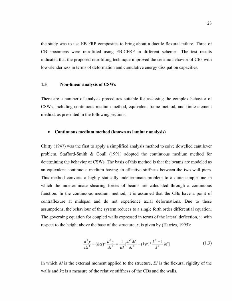
23
the study was to use EB-FRP composites to bring about a ductile flexural failure. Three of
CB specimens were retrofitted using EB-CFRP in different schemes. The test results
indicated that the proposed retrofitting technique improved the seismic behavior of CBs with
low-slenderness in terms of deformation and cumulative energy dissipation capacities.
1.5 Non-linear analysis of CSWs
There are a number of analysis procedures suitable for assessing the complex behavior of
CSWs, including continuous medium method, equivalent frame method, and finite element
method, as presented in the following sections.
• Continuous medium method (known as laminar analysis)
Chitty (1947) was the first to apply a simplified analysis method to solve dowelled cantilever
problem. Stafford-Smith & Coull (1991) adopted the continuous medium method for
determining the behavior of CSWs. The basis of this method is that the beams are modeled as
an equivalent continuous medium having an effective stiffness between the two wall piers.
This method converts a highly statically indeterminate problem to a quite simple one in
which the indeterminate shearing forces of beams are calculated through a continuous
function. In the continuous medium method, it is assumed that the CBs have a point of
contraflexure at midspan and do not experience axial deformations. Due to these
assumptions, the behaviour of the system reduces to a single forth order differential equation.
The governing equation for coupled walls expressed in terms of the lateral deflection, y, with
respect to the height above the base of the structure, z, is given by (Harries, 1995):
]
1)([
1)(
2
22
2
2
2
22
4
4
Mk
kk
dz
Md
EIdz
ydk
dz
yd −−=− αα (1.3)
In which M is the external moment applied to the structure, EI is the flexural rigidity of the
walls and kα is a measure of the relative stiffness of the CBs and the walls.
24
• Equivalent frame method
The frame analogy method is more appropriate for modeling complex coupled wall systems
such as CSWs with more than two wall piers or irregular wall configurations, the continuous
medium method being impractical for such walls. In this method the coupled wall structure is
modeled as a series of frame members in which each wall pier is represented by an
equivalent wide column member located at the centroid of the pier (Harries, 1995). The axial
and flexural rigidities (AE and EI) of the wide column members correspond to the actual wall
piers. The CBs are modeled by beam elements with appropriate structural properties. A part
of the wall pier which spans between the beam-wall joint and the effective column, is
modeled by rigid arms. These rigid arms are used to ensure that the correct rotations and
vertical displacements are achieved at the faces of the walls, and also to incorporate the
necessary condition that plane wall sections remain plane.
• Finite Element Models
The finite element method is the most powerful tool of analysis which can be applied to any
form of structures subjected to any type of loadings. There are a number of details that must
be addressed to carry out accurate analyses of coupled wall structures. The concrete and steel
modeling, the connection of the coupling beam to the wall, the bond between concrete and
steel, and the modelling of cracked regions are some of the important factors in CSW
modeling. Due to the nature of the response of coupled wall systems, nonlinear analysis
provides a better insight of the force resisting mechanisms within the system.
1.6 Previous studies on analysis of CSWs
Pala & Ozmen (1995) studied the frame modelling which consists of vertical wall parts and
horizontal CBs with specified infinitely rigid portions within the wall in idealization of
structural walls with openings for analysis. However, determination of the beam rigid length
to be considered is one of the problems of this idealization.
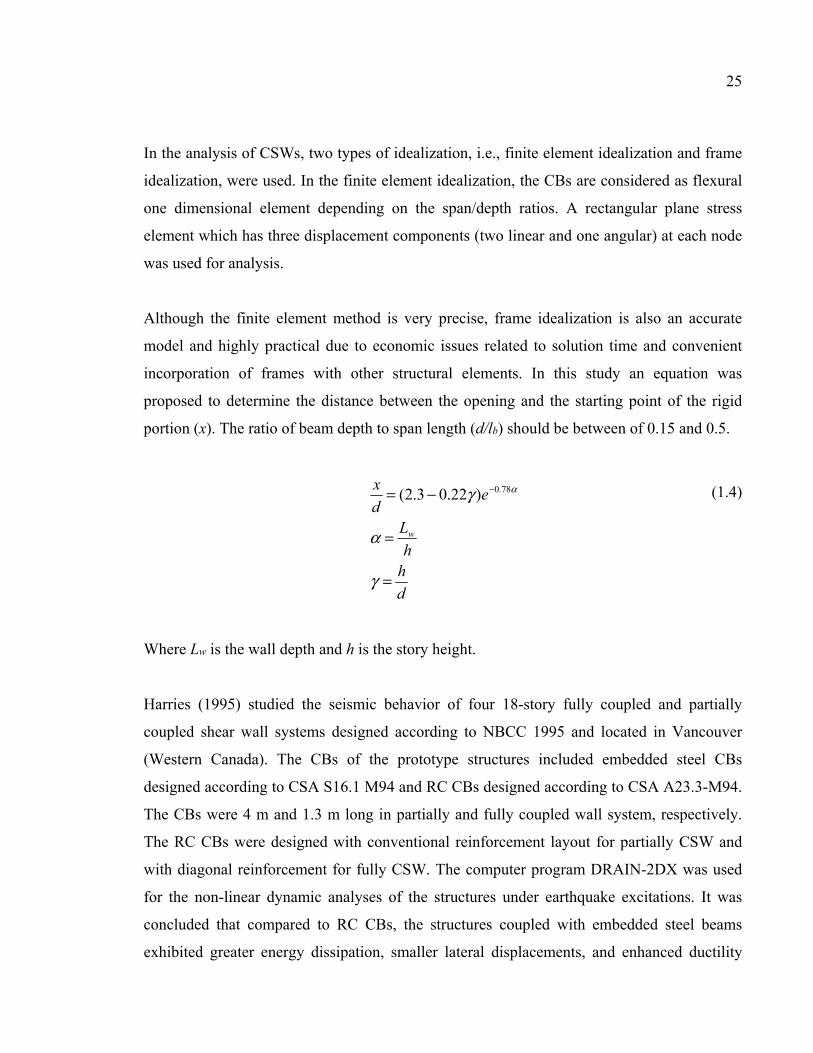
25
In the analysis of CSWs, two types of idealization, i.e., finite element idealization and frame
idealization, were used. In the finite element idealization, the CBs are considered as flexural
one dimensional element depending on the span/depth ratios. A rectangular plane stress
element which has three displacement components (two linear and one angular) at each node
was used for analysis.
Although the finite element method is very precise, frame idealization is also an accurate
model and highly practical due to economic issues related to solution time and convenient
incorporation of frames with other structural elements. In this study an equation was
proposed to determine the distance between the opening and the starting point of the rigid
portion (x). The ratio of beam depth to span length (d/lb) should be between of 0.15 and 0.5.
d
hh
L
ed
x
w
=
=
−= −
γ
α
γ α78.0)22.03.2(
(1.4)
Where Lw is the wall depth and h is the story height.
Harries (1995) studied the seismic behavior of four 18-story fully coupled and partially
coupled shear wall systems designed according to NBCC 1995 and located in Vancouver
(Western Canada). The CBs of the prototype structures included embedded steel CBs
designed according to CSA S16.1 M94 and RC CBs designed according to CSA A23.3-M94.
The CBs were 4 m and 1.3 m long in partially and fully coupled wall system, respectively.
The RC CBs were designed with conventional reinforcement layout for partially CSW and
with diagonal reinforcement for fully CSW. The computer program DRAIN-2DX was used
for the non-linear dynamic analyses of the structures under earthquake excitations. It was
concluded that compared to RC CBs, the structures coupled with embedded steel beams
exhibited greater energy dissipation, smaller lateral displacements, and enhanced ductility
26
without significant loss of strength or stiffness. The analyses were also conducted by another
computer program, RUAUMOKO, and similar results were obtained (Harries et al., 1998).
El-Tawil & Kuenzli (2002) investigated the effect of the coupling ratio on the inelastic
response of several hybrid coupled walls (HCWs) through pushover analysis according to
FEMA-273 (1997). To that end, 6-story and 12-story prototype systems with 0%
(uncoupled), 30%, 45%, and 60% coupling ratios were designed and modeled using the finite
element method. It was concluded that moderately HCW systems are well suited for
application in regions of high seismic risk. An over-coupling can induce large shear and
compressive axial loads in the wall resulting to detrimental behavior. In contrast, no coupling
resulted in poor behavior such as large base wall rotations, story drifts, shear distortions, and
deflections, and concrete crushing in the plastic hinge region.
McNiece (2004) investigated the behavior of 30-story coupled core wall structures in order to
compare the strength-based and performance-based design methodologies. To that end, non-
linear static and non-linear dynamic analyses were conducted on the prototype structure with
diagonally reinforced CBs under five ground acceleration records. It was concluded that the
conventional strength-based design methodologies result in CB shears exceeding the code-
prescribed limits. In contrast, the structure designed according to several performance
criteria, behaved well at the life safety performance level and adequately at the collapse
prevention level. However, higher mode effects had a significant effect on such structures as
a result of CB yielding which led to period elongation.
Boivin (2006) studied the seismic performance of a 12-storey ductile concrete core wall
building designed according to the NBCC 2005 and the CSA A23.3-04 located in the
Canadian city of Montreal. The prototype structure was analyzed through inelastic pushover
and time-history dynamic analyses using EFiCoS and RUAUMOKO program. It was
concluded that the concrete tension-stiffening effect plays a major role on predictions. Since
the seismic demand prediction at design level on the cantilever wall system was
underestimated in the design demand procedure, the shear strength requirement of the CSA
27
A23.3-04 was not adequate. Therefore, an additional plastic hinge formation occurred above
the walls’ base. In contrast, differences between the predicted and design shear force
demands were less for the coupled wall that confirms the adequacy of the NBCC 2005
spectral response acceleration for the seismic design of CCWs. However, the predicted shear
force demand at the base of the walls was underestimated due to ignoring the higher mode
effects.
Benazza (2012) studied the nonlinear behavior of 10, 20, and 30-story CSWs (60 specimens)
designed according to NBCC 2010 and CSA A23.3-04 in Canadian seismic zones. In this
study, the dynamic amplification of shear demand due to the inelastic effects of higher modes
was investigated. A reduction factor for shear was also proposed depending on the type of
coupling of the shear wall system. Furthermore, a new approach for generating seismic
signals compatible with the target spectrum of the NBCC code, was presented.
Eljadei (2012) investigated the structural behavior of a 12-storey reinforced concrete coupled
core wall building located in Seattle, Washington. Five dual CSW prototypes were
considered with different steel CBs and same reinforced concrete wall piers allowing the
study of the effects of decayed coupling action. The two wall piers in the CSW were
differently designed in terms of their dynamic and geometric properties. The results of the
nonlinear static and dynamic analyses of coupled core wall prototypes indicated that the dual
systems performed very well as they provided a superior lateral stiffness in the elastic range
and during the evolution of linked wall piers.
Arabzadeh (2017) studied two aspects of the seismic behavior of a 12-story coupled C-
shaped wall system located in Eastern North America: the effect of torsional irregularities on
the seismic collapse of the system and the efficiency of FRP composite retrofit in
enhancement of seismic behavior of the structure. The results of nonlinear dynamic analysis
of the coupled core wall structure indicated that torsional sensitivity can significantly
decrease the collapse capacity. However, it had no substantial influence on inter-story drift
components of the system.

28
It was also observed that FRP strengthening is an effective method for improving the
collapse resistance of RC core wall systems.
CHAPTER 2
SEISMIC UPGRADING OF RC COUPLED SHEAR WALLS : STATE OF THE ART AND RESEARCH NEEDS
Sara Honarparast a and Omar Chaallal b
a, b Department of Construction Engineering, École de Technologie Supérieure,
1100 Notre-Dame West, Montreal, Quebec, Canada H3C 1K3
Paper published in Global Journal of Advanced Engineering Technologies and Sciences, December, 2015.
2.1 Abstract
CSWs are one of the most efficient structural systems for resisting lateral loadings due to
wind and earthquakes. Their performance relies predominantly on CBs, which must be
appropriately designed and detailed to provide enhanced ductility and energy-absorption
capacity. Many existing buildings with CSWs were designed according to previous
generations of codes and standards. Therefore, they are not up to modern, more stringent
seismic codes and standards. Retrofitting CBs to improve their seismic performance can be a
viable and cost-effective option. The objective of this paper is threefold: (i) to identify the
deficiencies of existing CBs; (ii) to present a literature review of different techniques and
methods for retrofitting CBs to enhance their seismic performance; and (iii) to highlight the
advantages and disadvantages of these techniques. In addition, some strengthening
techniques used for beam-wall joints, which play an important role in providing shear
capacity for CSWs, are also presented. Finally, research needs for new and practical retrofit
methods to improve the seismic performance of existing CSWs are outlined.
2.2 Introduction
Past earthquakes have shown that most building structures collapse due to excessive
deformation. Therefore, deformation should be kept within acceptable limits to avoid
instability. Shear walls can be an effective system for resisting lateral forces. However, they
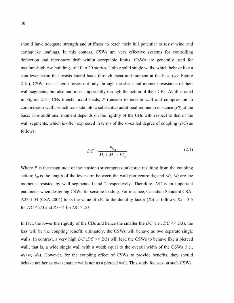
30
should have adequate strength and stiffness to reach their full potential to resist wind and
earthquake loadings. In this context, CSWs are very effective systems for controlling
deflection and inter-story drift within acceptable limits. CSWs are generally used for
medium-high rise buildings of 10 to 20 stories. Unlike solid single walls, which behave like a
cantilever beam that resists lateral loads through shear and moment at the base (see Figure
2.1a), CSWs resist lateral forces not only through the shear and moment resistance of their
wall segments, but also and most importantly through the action of their CBs. As illustrated
in Figure 2.1b, CBs transfer axial loads, P (tension to tension wall and compression to
compression wall), which translate into a substantial additional moment resistance (Pl) at the
base. This additional moment depends on the rigidity of the CBs with respect to that of the
wall segments, which is often expressed in terms of the so-called degree of coupling (DC) as
follows:
cg
cg
PlMM
PlDC
++=
21
(2.1)
Where P is the magnitude of the tension (or compression) force resulting from the coupling
action; lcg is the length of the lever arm between the wall pier centroids; and M1, M2 are the
moments resisted by wall segments 1 and 2 respectively. Therefore, DC is an important
parameter when designing CSWs for seismic loading. For instance, Canadian Standard CSA-
A23.3-04 (CSA 2004) links the value of DC to the ductility factor (Rd) as follows: Rd = 3.5
for DC ≤ 2/3 and Rd = 4 for DC > 2/3.
In fact, the lower the rigidity of the CBs and hence the smaller the DC (i.e., DC << 2/3), the
less will be the coupling benefit; ultimately, the CSWs will behave as two separate single
walls. In contrast, a very high DC (DC >> 2/3) will lead the CSWs to behave like a pierced
wall, that is, a wide single wall with a width equal to the overall width of the CSWs (i.e.,
w1+w2+dw). However, for the coupling effect of CSWs to provide benefits, they should
behave neither as two separate walls nor as a pierced wall. This study focuses on such CSWs.
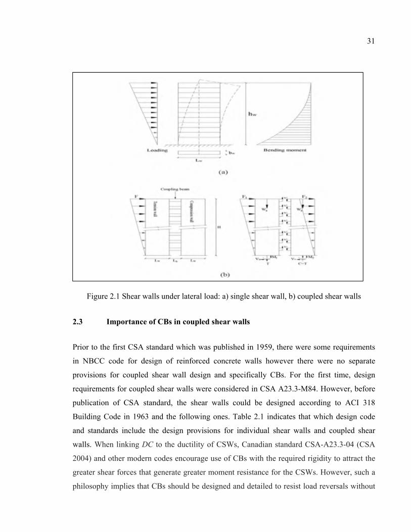
31
Figure 2.1 Shear walls under lateral load: a) single shear wall, b) coupled shear walls
2.3 Importance of CBs in coupled shear walls
Prior to the first CSA standard which was published in 1959, there were some requirements
in NBCC code for design of reinforced concrete walls however there were no separate
provisions for coupled shear wall design and specifically CBs. For the first time, design
requirements for coupled shear walls were considered in CSA A23.3-M84. However, before
publication of CSA standard, the shear walls could be designed according to ACI 318
Building Code in 1963 and the following ones. Table 2.1 indicates that which design code
and standards include the design provisions for individual shear walls and coupled shear
walls. When linking DC to the ductility of CSWs, Canadian standard CSA-A23.3-04 (CSA
2004) and other modern codes encourage use of CBs with the required rigidity to attract the
greater shear forces that generate greater moment resistance for the CSWs. However, such a
philosophy implies that CBs should be designed and detailed to resist load reversals without
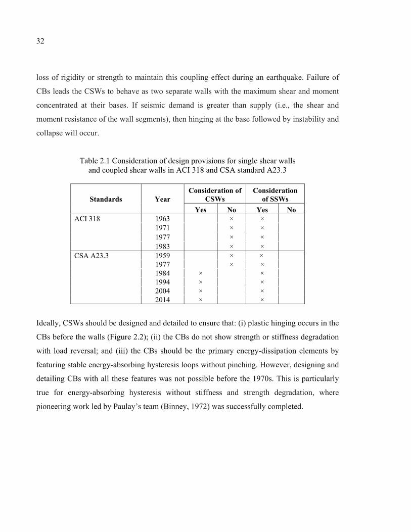
32
loss of rigidity or strength to maintain this coupling effect during an earthquake. Failure of
CBs leads the CSWs to behave as two separate walls with the maximum shear and moment
concentrated at their bases. If seismic demand is greater than supply (i.e., the shear and
moment resistance of the wall segments), then hinging at the base followed by instability and
collapse will occur.
Table 2.1 Consideration of design provisions for single shear walls and coupled shear walls in ACI 318 and CSA standard A23.3
Standards Year Consideration of
CSWs Consideration
of SSWs
Yes No Yes No ACI 318 1963 × × 1971 × × 1977 × × 1983 × × CSA A23.3 1959 × ×
1977 × × 1984 × × 1994 × × 2004 × × 2014 × ×
Ideally, CSWs should be designed and detailed to ensure that: (i) plastic hinging occurs in the
CBs before the walls (Figure 2.2); (ii) the CBs do not show strength or stiffness degradation
with load reversal; and (iii) the CBs should be the primary energy-dissipation elements by
featuring stable energy-absorbing hysteresis loops without pinching. However, designing and
detailing CBs with all these features was not possible before the 1970s. This is particularly
true for energy-absorbing hysteresis without stiffness and strength degradation, where
pioneering work led by Paulay’s team (Binney, 1972) was successfully completed.
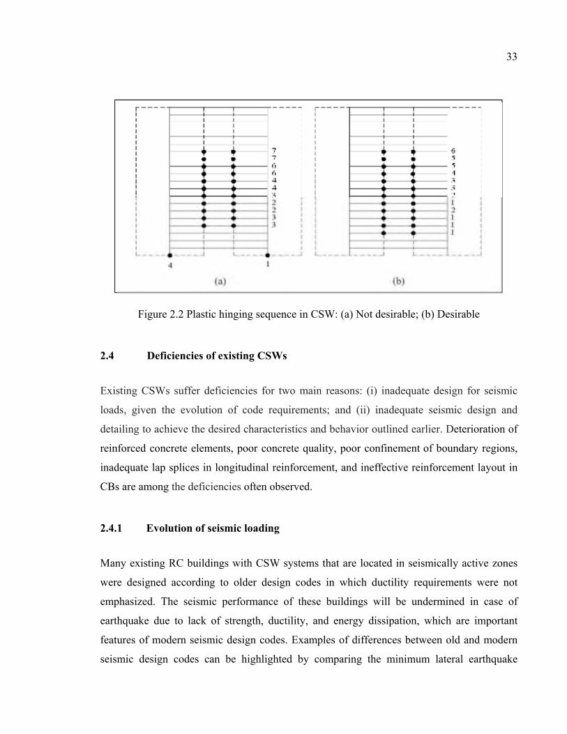
33
Figure 2.2 Plastic hinging sequence in CSW: (a) Not desirable; (b) Desirable
2.4 Deficiencies of existing CSWs
Existing CSWs suffer deficiencies for two main reasons: (i) inadequate design for seismic
loads, given the evolution of code requirements; and (ii) inadequate seismic design and
detailing to achieve the desired characteristics and behavior outlined earlier. Deterioration of
reinforced concrete elements, poor concrete quality, poor confinement of boundary regions,
inadequate lap splices in longitudinal reinforcement, and ineffective reinforcement layout in
CBs are among the deficiencies often observed.
2.4.1 Evolution of seismic loading
Many existing RC buildings with CSW systems that are located in seismically active zones
were designed according to older design codes in which ductility requirements were not
emphasized. The seismic performance of these buildings will be undermined in case of
earthquake due to lack of strength, ductility, and energy dissipation, which are important
features of modern seismic design codes. Examples of differences between old and modern
seismic design codes can be highlighted by comparing the minimum lateral earthquake
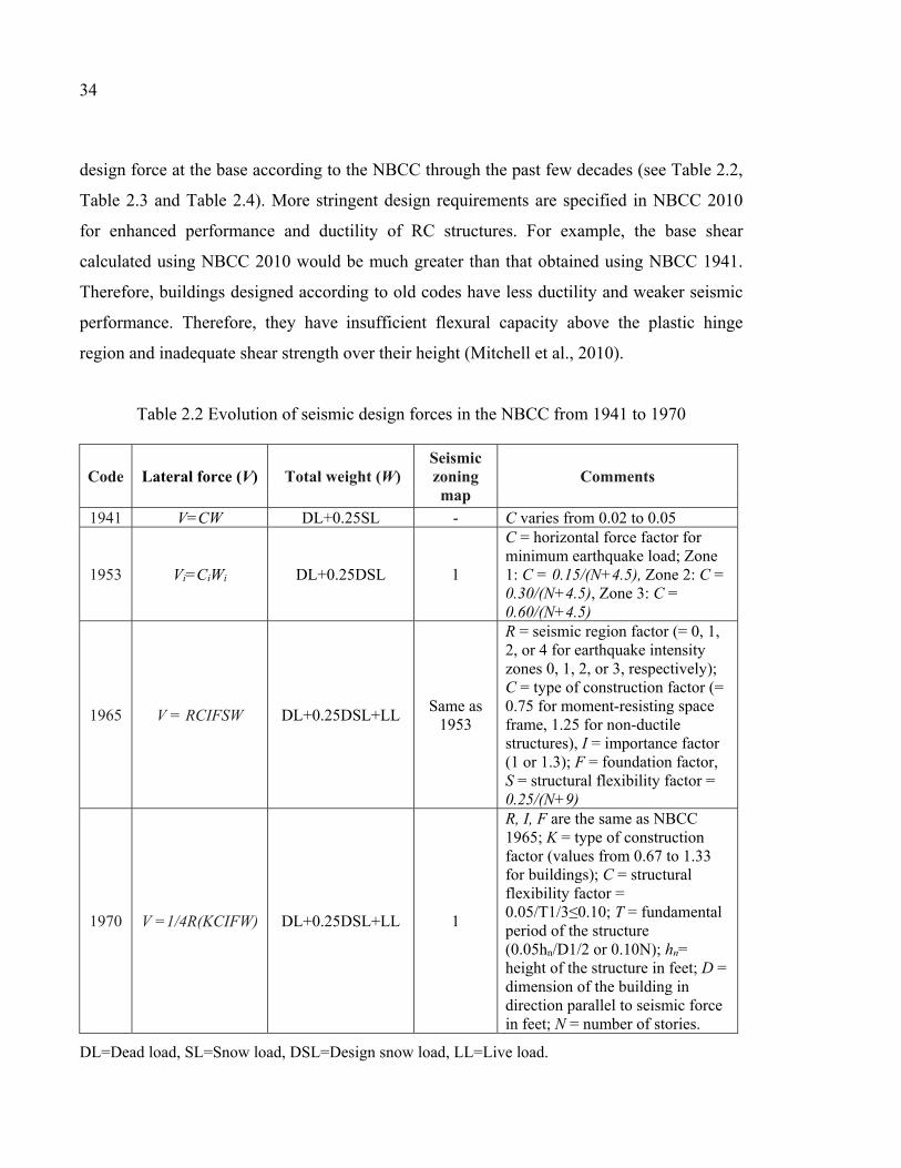
34
design force at the base according to the NBCC through the past few decades (see Table 2.2,
Table 2.3 and Table 2.4). More stringent design requirements are specified in NBCC 2010
for enhanced performance and ductility of RC structures. For example, the base shear
calculated using NBCC 2010 would be much greater than that obtained using NBCC 1941.
Therefore, buildings designed according to old codes have less ductility and weaker seismic
performance. Therefore, they have insufficient flexural capacity above the plastic hinge
region and inadequate shear strength over their height (Mitchell et al., 2010).
Table 2.2 Evolution of seismic design forces in the NBCC from 1941 to 1970
Code Lateral force (V) Total weight (W) Seismic zoning map
Comments
1941 V=CW DL+0.25SL - C varies from 0.02 to 0.05
1953 Vi=CiWi DL+0.25DSL 1
C = horizontal force factor for minimum earthquake load; Zone 1: C = 0.15/(N+4.5), Zone 2: C = 0.30/(N+4.5), Zone 3: C = 0.60/(N+4.5)
1965 V = RCIFSW DL+0.25DSL+LL Same as 1953
R = seismic region factor (= 0, 1, 2, or 4 for earthquake intensity zones 0, 1, 2, or 3, respectively); C = type of construction factor (= 0.75 for moment-resisting space frame, 1.25 for non-ductile structures), I = importance factor (1 or 1.3); F = foundation factor, S = structural flexibility factor = 0.25/(N+9)
1970 V =1/4R(KCIFW) DL+0.25DSL+LL 1
R, I, F are the same as NBCC 1965; K = type of construction factor (values from 0.67 to 1.33 for buildings); C = structural flexibility factor = 0.05/T1/3≤0.10; T = fundamental period of the structure (0.05hn/D1/2 or 0.10N); hn= height of the structure in feet; D = dimension of the building in direction parallel to seismic force in feet; N = number of stories.
DL=Dead load, SL=Snow load, DSL=Design snow load, LL=Live load.
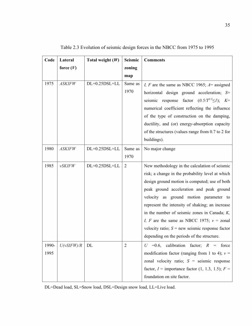
35
Table 2.3 Evolution of seismic design forces in the NBCC from 1975 to 1995 Code Lateral
force (V)
Total weight (W) Seismic
zoning
map
Comments
1975 ASKIFW DL+0.25DSL+LL Same as
1970
I, F are the same as NBCC 1965; A= assigned
horizontal design ground acceleration; S=
seismic response factor (0.5/T1/3≤1); K=
numerical coefficient reflecting the influence
of the type of construction on the damping,
ductility, and (or) energy-absorption capacity
of the structures (values range from 0.7 to 2 for
buildings).
1980 ASKIFW DL+0.25DSL+LL Same as
1970
No major change
1985 vSKIFW DL+0.25DSL+LL 2 New methodology in the calculation of seismic
risk; a change in the probability level at which
design ground motion is computed; use of both
peak ground acceleration and peak ground
velocity as ground motion parameter to
represent the intensity of shaking; an increase
in the number of seismic zones in Canada; K,
I, F are the same as NBCC 1975; v = zonal
velocity ratio; S = new seismic response factor
depending on the periods of the structure.
1990-
1995
U(vSIFW)/R DL 2 U =0.6, calibration factor; R = force
modification factor (ranging from 1 to 4); v =
zonal velocity ratio; S = seismic response
factor, I = importance factor (1, 1.3, 1.5); F =
foundation on site factor.
DL=Dead load, SL=Snow load, DSL=Design snow load, LL=Live load.
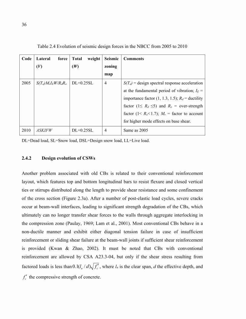
36
Table 2.4 Evolution of seismic design forces in the NBCC from 2005 to 2010 Code Lateral force
(V)
Total weight
(W)
Seismic
zoning
map
Comments
2005 S(Ta)MvIEW/RdRo DL+0.25SL 4 S(Ta) = design spectral response acceleration
at the fundamental period of vibration; IE =
importance factor (1, 1.3, 1.5); Rd = ductility
factor (1≤ Rd ≤5) and Ro = over-strength
factor (1< Ro<1.7); Mv = factor to account
for higher mode effects on base shear.
2010 ASKIFW DL+0.25SL 4 Same as 2005
DL=Dead load, SL=Snow load, DSL=Design snow load, LL=Live load.
2.4.2 Design evolution of CSWs
Another problem associated with old CBs is related to their conventional reinforcement
layout, which features top and bottom longitudinal bars to resist flexure and closed vertical
ties or stirrups distributed along the length to provide shear resistance and some confinement
of the cross section (Figure 2.3a). After a number of post-elastic load cycles, severe cracks
occur at beam-wall interfaces, leading to significant strength degradation of the CBs, which
ultimately can no longer transfer shear forces to the walls through aggregate interlocking in
the compression zone (Paulay, 1969; Lam et al., 2001). Most conventional CBs behave in a
non-ductile manner and exhibit either diagonal tension failure in case of insufficient
reinforcement or sliding shear failure at the beam-wall joints if sufficient shear reinforcement
is provided (Kwan & Zhao, 2002). It must be noted that CBs with conventional
reinforcement are allowed by CSA A23.3-04, but only if the shear stress resulting from
factored loads is less than cu fdl ′)/(1.0 , where lu is the clear span, d the effective depth, and
cf ′ the compressive strength of concrete.
37
The load-displacement curves of conventionally reinforced CBs, especially at large
deflection amplitude, exhibit considerable pinching, which causes rapid stiffness degradation
and hence relatively low energy dissipation (Figure 2.3b). This may be attributed to widening
of shear and flexural cracks, which leads to excessive inelastic deflection of conventionally
reinforced CBs (Kwan & Zhao, 2002).
2.5 Diagonal reinforcement concept for CBs
The pioneering work led by Paulay’s team and others (Binney, 1972; Santhakumar, 1974;
Shiu et al., 1978; Tassios et al., 1996; Galano & Vignoli, 2000; Kwan & Zhao, 2002) on the
subject of CSWs and CBs opened a whole new era for the design of such structural elements,
in particular the development of CBs with diagonal reinforcement (Figure 2.3c) as opposed
to conventional reinforcement. Diagonally reinforced CBs showed highly satisfactory
behavior under cyclic loading and achieved all the desired strength, stiffness, ductility, and
hysteresis stability characteristics (Figure 2.3d). Therefore, the concept has been accepted
and adopted worldwide. It is now part of most modern seismic design codes and guidelines.
The diagonal reinforcement extends through the entire CB. It provides both flexural and
shear resistance, greatly improving CB ductility. In such CBs, shear force is transferred from
one wall to the other, dividing itself into diagonal tension and compression forces which
intersect at mid-span where there is no moment (Figure 2.4). Extending diagonal
reinforcement beyond the beam ends improves hysteretic behavior by preventing sliding
shear and by spreading the hinging regions away from the wall face (Paulay, 1974). This
translates into a more stable load-displacement hysteresis without undesirable pinching
effects. Opening and closing of cracks in the concrete have little effect on CB lateral
resistance because this lateral resistance does not rely on the beam compression developed in
the concrete (Kwan & Zhao, 2002). However, sudden failure of the CB is possible due to
buckling of the diagonal reinforcing bars. This is the main concern when designing CSWs
with diagonally reinforced CBs. Therefore, to keep the surrounding concrete in place and
delay or prevent buckling failure, sufficient lateral hoops should be provided along the
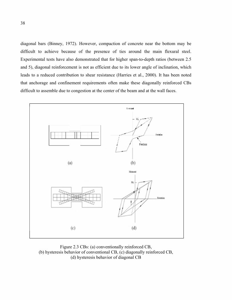
38
diagonal bars (Binney, 1972). However, compaction of concrete near the bottom may be
difficult to achieve because of the presence of ties around the main flexural steel.
Experimental tests have also demonstrated that for higher span-to-depth ratios (between 2.5
and 5), diagonal reinforcement is not as efficient due to its lower angle of inclination, which
leads to a reduced contribution to shear resistance (Harries et al., 2000). It has been noted
that anchorage and confinement requirements often make these diagonally reinforced CBs
difficult to assemble due to congestion at the center of the beam and at the wall faces.
Figure 2.3 CBs: (a) conventionally reinforced CB, (b) hysteresis behavior of conventional CB, (c) diagonally reinforced CB,
(d) hysteresis behavior of diagonal CB
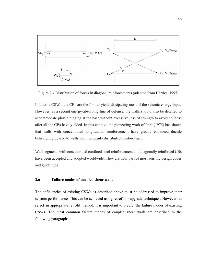
39
Figure 2.4 Distribution of forces in diagonal reinforcements (adapted from Harries, 1995)
In ductile CSWs, the CBs are the first to yield, dissipating most of the seismic energy input.
However, as a second energy-absorbing line of defense, the walls should also be detailed to
accommodate plastic hinging at the base without excessive loss of strength to avoid collapse
after all the CBs have yielded. In this context, the pioneering work of Park (1975) has shown
that walls with concentrated longitudinal reinforcement have greatly enhanced ductile
behavior compared to walls with uniformly distributed reinforcement.
Wall segments with concentrated confined steel reinforcement and diagonally reinforced CBs
have been accepted and adopted worldwide. They are now part of most seismic design codes
and guidelines.
2.6 Failure modes of coupled shear walls
The deficiencies of existing CSWs as described above must be addressed to improve their
seismic performance. This can be achieved using retrofit or upgrade techniques. However, to
select an appropriate retrofit method, it is important to predict the failure modes of existing
CSWs. The most common failure modes of coupled shear walls are described in the
following paragraphs.
40
2.6.1 Flexural failure mode
In this failure mode, flexural cracks form first in the tension wall. However, flexural cracks
also develop at the junctions of the walls and the CBs, particularly at high stress levels. As
the load is increased, new flexural cracks may develop along the height of the wall and may
also spread to more CBs, as illustrated in Figure 2.5a. Finally, crushing of the compression
wall at the highly stressed corner and spreading of flexural cracks in most of the CBs lead to
failure of the wall (Subedi, 1991).
2.6.2 Shear failure mode
This failure mode, which is common in CSWs with moderate to deep reinforced CBs, starts
with formation of flexural cracks in the tension wall, with some minor flexural cracks at wall
junctions with CBs at high stress levels (Subedi, 1991). However, the main feature of this
failure mode is the formation of diagonal cracks which initiate near the center of the CBs and
spread across the compression diagonal. As the load is increased, new flexural cracks form
along the height of the wall simultaneously with the spread of shear cracks into other CBs.
Finally, failure of the CSWs occurs by shear failure in most of the CBs and by crushing of
the compression wall, as indicated in Figure 2.5b.
There are two possible shear failure modes: shear tension and shear sliding. The shear-
tension mode of failure is characterized by: (i) formation of numerous diagonal cracks in the
CB, (ii) yielding of the shear reinforcement before failure, and (iii) opening up of diagonal
cracks until complete failure. In contrast, the shear-sliding mode of failure is characterized
by: (i) formation of deep flexural cracks at the beam-wall joints, (ii) sliding movement along
cracks at the beam-wall joints during failure, and (iii) reliance on the dowel action of the
longitudinal reinforcing bars at beam-wall joints for residual shear strength in the post-peak
stage. Although both modes of shear failure are brittle in nature, the brittleness of the shear-
sliding failure mode is more severe because it is not preceded by yielding of the shear
reinforcement, unlike the shear-tension mode. Therefore, when designing deep CBs,
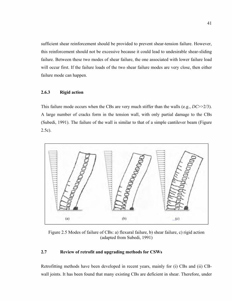
41
sufficient shear reinforcement should be provided to prevent shear-tension failure. However,
this reinforcement should not be excessive because it could lead to undesirable shear-sliding
failure. Between these two modes of shear failure, the one associated with lower failure load
will occur first. If the failure loads of the two shear failure modes are very close, then either
failure mode can happen.
2.6.3 Rigid action
This failure mode occurs when the CBs are very much stiffer than the walls (e.g., DC>>2/3).
A large number of cracks form in the tension wall, with only partial damage to the CBs
(Subedi, 1991). The failure of the wall is similar to that of a simple cantilever beam (Figure
2.5c).
Figure 2.5 Modes of failure of CBs: a) flexural failure, b) shear failure, c) rigid action (adapted from Subedi, 1991)
2.7 Review of retrofit and upgrading methods for CSWs
Retrofitting methods have been developed in recent years, mainly for (i) CBs and (ii) CB-
wall joints. It has been found that many existing CBs are deficient in shear. Therefore, under
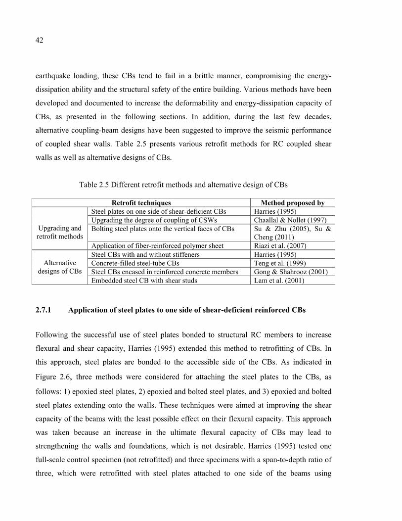
42
earthquake loading, these CBs tend to fail in a brittle manner, compromising the energy-
dissipation ability and the structural safety of the entire building. Various methods have been
developed and documented to increase the deformability and energy-dissipation capacity of
CBs, as presented in the following sections. In addition, during the last few decades,
alternative coupling-beam designs have been suggested to improve the seismic performance
of coupled shear walls. Table 2.5 presents various retrofit methods for RC coupled shear
walls as well as alternative designs of CBs.
Table 2.5 Different retrofit methods and alternative design of CBs
Retrofit techniques Method proposed by Upgrading and retrofit methods
Steel plates on one side of shear-deficient CBs Harries (1995) Upgrading the degree of coupling of CSWs Chaallal & Nollet (1997) Bolting steel plates onto the vertical faces of CBs Su & Zhu (2005), Su &
Cheng (2011) Application of fiber-reinforced polymer sheet Riazi et al. (2007)
Alternative
designs of CBs
Steel CBs with and without stiffeners Harries (1995) Concrete-filled steel-tube CBs Teng et al. (1999) Steel CBs encased in reinforced concrete members Gong & Shahrooz (2001) Embedded steel CB with shear studs Lam et al. (2001)
2.7.1 Application of steel plates to one side of shear-deficient reinforced CBs
Following the successful use of steel plates bonded to structural RC members to increase
flexural and shear capacity, Harries (1995) extended this method to retrofitting of CBs. In
this approach, steel plates are bonded to the accessible side of the CBs. As indicated in
Figure 2.6, three methods were considered for attaching the steel plates to the CBs, as
follows: 1) epoxied steel plates, 2) epoxied and bolted steel plates, and 3) epoxied and bolted
steel plates extending onto the walls. These techniques were aimed at improving the shear
capacity of the beams with the least possible effect on their flexural capacity. This approach
was taken because an increase in the ultimate flexural capacity of CBs may lead to
strengthening the walls and foundations, which is not desirable. Harries (1995) tested one
full-scale control specimen (not retrofitted) and three specimens with a span-to-depth ratio of
three, which were retrofitted with steel plates attached to one side of the beams using
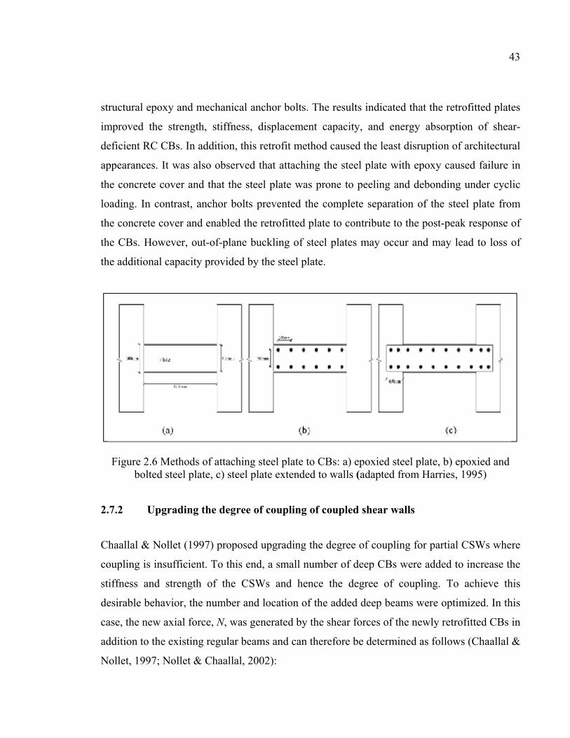
43
structural epoxy and mechanical anchor bolts. The results indicated that the retrofitted plates
improved the strength, stiffness, displacement capacity, and energy absorption of shear-
deficient RC CBs. In addition, this retrofit method caused the least disruption of architectural
appearances. It was also observed that attaching the steel plate with epoxy caused failure in
the concrete cover and that the steel plate was prone to peeling and debonding under cyclic
loading. In contrast, anchor bolts prevented the complete separation of the steel plate from
the concrete cover and enabled the retrofitted plate to contribute to the post-peak response of
the CBs. However, out-of-plane buckling of steel plates may occur and may lead to loss of
the additional capacity provided by the steel plate.
Figure 2.6 Methods of attaching steel plate to CBs: a) epoxied steel plate, b) epoxied and bolted steel plate, c) steel plate extended to walls (adapted from Harries, 1995)
2.7.2 Upgrading the degree of coupling of coupled shear walls
Chaallal & Nollet (1997) proposed upgrading the degree of coupling for partial CSWs where
coupling is insufficient. To this end, a small number of deep CBs were added to increase the
stiffness and strength of the CSWs and hence the degree of coupling. To achieve this
desirable behavior, the number and location of the added deep beams were optimized. In this
case, the new axial force, N, was generated by the shear forces of the newly retrofitted CBs in
addition to the existing regular beams and can therefore be determined as follows (Chaallal &
Nollet, 1997; Nollet & Chaallal, 2002):
44
=
+=H n
iiNdxxN
01
)(υ (2.2)
Where ν(x) is the shear force intensity in the regular coupling system and Ni is the axial force
related to the retrofitted CBs. The advantage of this method is that by optimizing the number
and location of the new attached CBs, the solution can be made cost-effective. Furthermore,
using this retrofit method results in minimal reduction of the clearance for passage of
services along corridors.
2.7.3 Attaching external steel plates to the side faces of CBs
To strengthen CBs, Su & Zhu (2005) used steel plates bolted onto their side faces (Figure
2.7). Thereby, the bending moments and shear forces were transferred from the steel plates to
the wall using appropriate bolt positions. To evaluate the performance of this retrofit method,
three RC CBs with a span length-to-depth ratio of 2.5 and different steel plate arrangements
were tested under cyclic loading. The first specimen was considered as a control beam with
conventional reinforcement layout, whereas the second and third specimens were retrofitted
with 3-mm and 6-mm thick steel plates respectively. The test results revealed that the steel
plates increased the stiffness, strength, and deformability of the CBs. However, ultimate
failure was due to crushing of concrete and excessive deformation. In addition, by attaching
ductile steel plates, the maximum nominal ductility factor (yn
un θ
θμ = ) and the maximum
ductility factor (y
uθ
θμ = ) were reduced due to an increase in yield rotation (θy) much
greater than the ultimate rotation angle (θu). Moreover, local buckling instability of the plate
was observed near the beam-wall joints, indicating that the applied diagonal compressive
forces resulting from a combination of bending, shear, and axial forces were greater than the
critical limit (Su & Zhu, 2005).
Due to buckling of steel plates in the retrofit method proposed by Su & Zhu (2005) and lack
of research into strengthening of CBs with span-to-depth ratios less than two, Su & Cheng
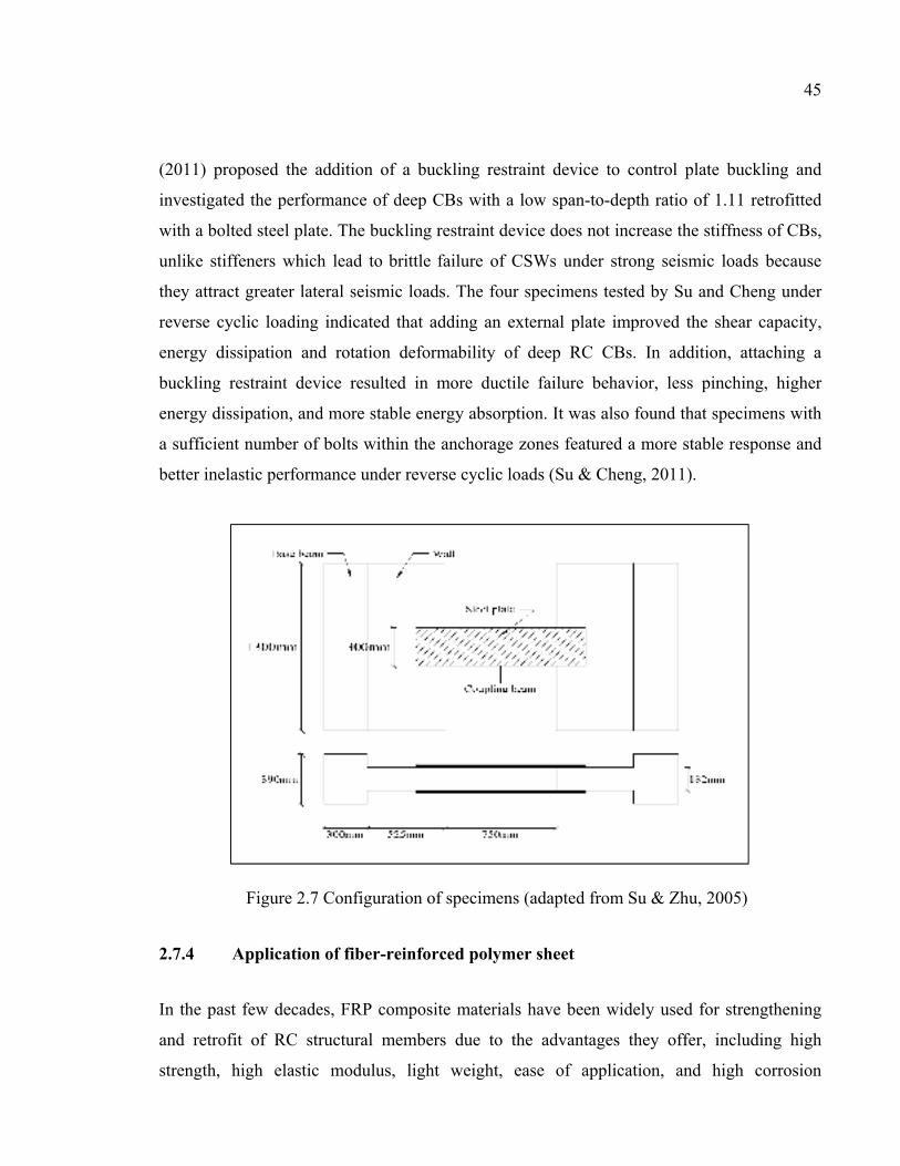
45
(2011) proposed the addition of a buckling restraint device to control plate buckling and
investigated the performance of deep CBs with a low span-to-depth ratio of 1.11 retrofitted
with a bolted steel plate. The buckling restraint device does not increase the stiffness of CBs,
unlike stiffeners which lead to brittle failure of CSWs under strong seismic loads because
they attract greater lateral seismic loads. The four specimens tested by Su and Cheng under
reverse cyclic loading indicated that adding an external plate improved the shear capacity,
energy dissipation and rotation deformability of deep RC CBs. In addition, attaching a
buckling restraint device resulted in more ductile failure behavior, less pinching, higher
energy dissipation, and more stable energy absorption. It was also found that specimens with
a sufficient number of bolts within the anchorage zones featured a more stable response and
better inelastic performance under reverse cyclic loads (Su & Cheng, 2011).
Figure 2.7 Configuration of specimens (adapted from Su & Zhu, 2005)
2.7.4 Application of fiber-reinforced polymer sheet
In the past few decades, FRP composite materials have been widely used for strengthening
and retrofit of RC structural members due to the advantages they offer, including high
strength, high elastic modulus, light weight, ease of application, and high corrosion
46
resistance. The three most used fiber types for structural retrofits are glass, carbon, and
aramid. The choice depends on the required strength and stiffness, durability considerations,
cost, and availability of the FRP materials. Moreover, using FRP composites is a faster and
easier retrofitting method in special cases where evacuation of the entire building is not
feasible.
Riazi et al. (2007) investigated the behavior of conventional RC CBs in shear walls
strengthened with CFRP sheets. After test failure of four CBs having different
reinforcements, but with similar shear strength, two of them were rehabilitated, strengthened
with CFRP sheets, and retested. The test results indicated that the CBs rehabilitated with
CFRP sheets achieved enhanced strength in comparison with the original beams.
Meftah et al. (2013) strengthened both sides of CBs using CFRP plates to investigate the
dynamic behavior of RC CSWs. They developed new finite-element models for both the
walls and the strengthened CBs and carried out various analyses, including static and free
vibration analysis and dynamic analysis under El Centro and Northridge earthquake
accelerations. The results of comparing the maximum top lateral deflection responses of
strengthened and unstrengthened RC CSWs indicated that the geometric characteristics of the
shear wall structure and the dominant range frequencies of the input earthquake accelerations
affected the mitigation of seismic behavior achieved by strengthened RC coupled shear
walls.
Yeghnem et al. (2013) investigated the effect of creep and shrinkage of RC coupled shear-
wall structures strengthened using CFRP sheets with different spacings bonded to the bottom
of the CSWs. A finite-element lateral stiffness model was presented and used to analyze a
25-story CSW under two recorded earthquake accelerations from Algeria to verify the
accuracy of the proposed method. It was concluded that bonding CFRP sheets at the wall
edges resulted in improved displacement response. However, the predominant actions of
creep and shrinkage resulted in an increase in lateral displacement with time.
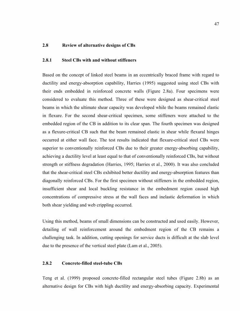
47
2.8 Review of alternative designs of CBs
2.8.1 Steel CBs with and without stiffeners
Based on the concept of linked steel beams in an eccentrically braced frame with regard to
ductility and energy-absorption capability, Harries (1995) suggested using steel CBs with
their ends embedded in reinforced concrete walls (Figure 2.8a). Four specimens were
considered to evaluate this method. Three of these were designed as shear-critical steel
beams in which the ultimate shear capacity was developed while the beams remained elastic
in flexure. For the second shear-critical specimen, some stiffeners were attached to the
embedded region of the CB in addition to its clear span. The fourth specimen was designed
as a flexure-critical CB such that the beam remained elastic in shear while flexural hinges
occurred at either wall face. The test results indicated that flexure-critical steel CBs were
superior to conventionally reinforced CBs due to their greater energy-absorbing capability,
achieving a ductility level at least equal to that of conventionally reinforced CBs, but without
strength or stiffness degradation (Harries, 1995; Harries et al., 2000). It was also concluded
that the shear-critical steel CBs exhibited better ductility and energy-absorption features than
diagonally reinforced CBs. For the first specimen without stiffeners in the embedded region,
insufficient shear and local buckling resistance in the embedment region caused high
concentrations of compressive stress at the wall faces and inelastic deformation in which
both shear yielding and web crippling occurred.
Using this method, beams of small dimensions can be constructed and used easily. However,
detailing of wall reinforcement around the embedment region of the CB remains a
challenging task. In addition, cutting openings for service ducts is difficult at the slab level
due to the presence of the vertical steel plate (Lam et al., 2005).
2.8.2 Concrete-filled steel-tube CBs
Teng et al. (1999) proposed concrete-filled rectangular steel tubes (Figure 2.8b) as an
alternative design for CBs with high ductility and energy-absorbing capacity. Experimental
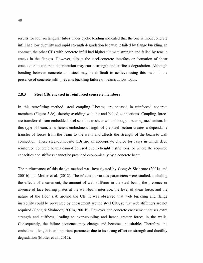
48
results for four rectangular tubes under cyclic loading indicated that the one without concrete
infill had low ductility and rapid strength degradation because it failed by flange buckling. In
contrast, the other CBs with concrete infill had higher ultimate strength and failed by tensile
cracks in the flanges. However, slip at the steel-concrete interface or formation of shear
cracks due to concrete deterioration may cause strength and stiffness degradation. Although
bonding between concrete and steel may be difficult to achieve using this method, the
presence of concrete infill prevents buckling failure of beams at low loads.
2.8.3 Steel CBs encased in reinforced concrete members
In this retrofitting method, steel coupling I-beams are encased in reinforced concrete
members (Figure 2.8c), thereby avoiding welding and bolted connections. Coupling forces
are transferred from embedded steel sections to shear walls through a bearing mechanism. In
this type of beam, a sufficient embedment length of the steel section creates a dependable
transfer of forces from the beam to the walls and affects the strength of the beam-to-wall
connection. These steel-composite CBs are an appropriate choice for cases in which deep
reinforced concrete beams cannot be used due to height restrictions, or where the required
capacities and stiffness cannot be provided economically by a concrete beam.
The performance of this design method was investigated by Gong & Shahrooz (2001a and
2001b) and Motter et al. (2012). The effects of various parameters were studied, including
the effects of encasement, the amount of web stiffener in the steel beam, the presence or
absence of face bearing plates at the wall-beam interface, the level of shear force, and the
nature of the floor slab around the CB. It was observed that web buckling and flange
instability could be prevented by encasement around steel CBs, so that web stiffeners are not
required (Gong & Shahrooz, 2001a, 2001b). However, the concrete encasement causes extra
strength and stiffness, leading to over-coupling and hence greater forces in the walls.
Consequently, the failure sequence may change and become undesirable. Therefore, the
embedment length is an important parameter due to its strong effect on strength and ductility
degradation (Motter et al., 2012).
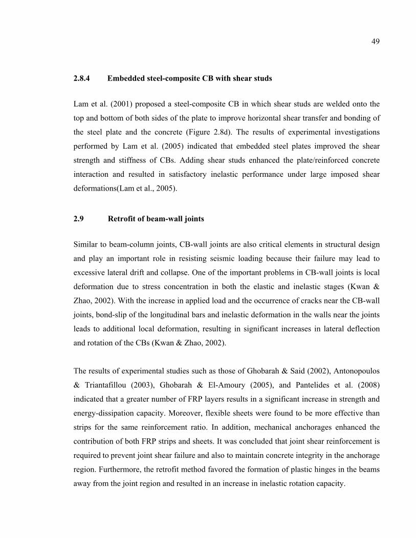
49
2.8.4 Embedded steel-composite CB with shear studs
Lam et al. (2001) proposed a steel-composite CB in which shear studs are welded onto the
top and bottom of both sides of the plate to improve horizontal shear transfer and bonding of
the steel plate and the concrete (Figure 2.8d). The results of experimental investigations
performed by Lam et al. (2005) indicated that embedded steel plates improved the shear
strength and stiffness of CBs. Adding shear studs enhanced the plate/reinforced concrete
interaction and resulted in satisfactory inelastic performance under large imposed shear
deformations(Lam et al., 2005).
2.9 Retrofit of beam-wall joints
Similar to beam-column joints, CB-wall joints are also critical elements in structural design
and play an important role in resisting seismic loading because their failure may lead to
excessive lateral drift and collapse. One of the important problems in CB-wall joints is local
deformation due to stress concentration in both the elastic and inelastic stages (Kwan &
Zhao, 2002). With the increase in applied load and the occurrence of cracks near the CB-wall
joints, bond-slip of the longitudinal bars and inelastic deformation in the walls near the joints
leads to additional local deformation, resulting in significant increases in lateral deflection
and rotation of the CBs (Kwan & Zhao, 2002).
The results of experimental studies such as those of Ghobarah & Said (2002), Antonopoulos
& Triantafillou (2003), Ghobarah & El-Amoury (2005), and Pantelides et al. (2008)
indicated that a greater number of FRP layers results in a significant increase in strength and
energy-dissipation capacity. Moreover, flexible sheets were found to be more effective than
strips for the same reinforcement ratio. In addition, mechanical anchorages enhanced the
contribution of both FRP strips and sheets. It was concluded that joint shear reinforcement is
required to prevent joint shear failure and also to maintain concrete integrity in the anchorage
region. Furthermore, the retrofit method favored the formation of plastic hinges in the beams
away from the joint region and resulted in an increase in inelastic rotation capacity.
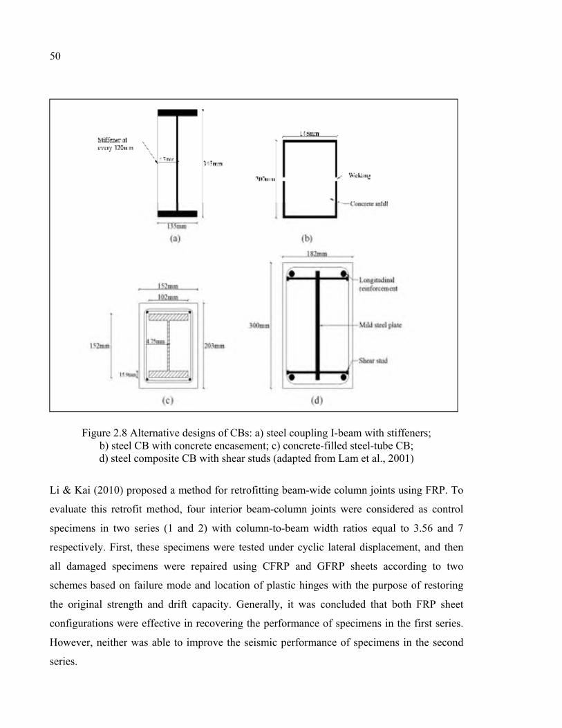
50
Figure 2.8 Alternative designs of CBs: a) steel coupling I-beam with stiffeners; b) steel CB with concrete encasement; c) concrete-filled steel-tube CB; d) steel composite CB with shear studs (adapted from Lam et al., 2001)
Li & Kai (2010) proposed a method for retrofitting beam-wide column joints using FRP. To
evaluate this retrofit method, four interior beam-column joints were considered as control
specimens in two series (1 and 2) with column-to-beam width ratios equal to 3.56 and 7
respectively. First, these specimens were tested under cyclic lateral displacement, and then
all damaged specimens were repaired using CFRP and GFRP sheets according to two
schemes based on failure mode and location of plastic hinges with the purpose of restoring
the original strength and drift capacity. Generally, it was concluded that both FRP sheet
configurations were effective in recovering the performance of specimens in the first series.
However, neither was able to improve the seismic performance of specimens in the second
series.
51
Parvin et al. (2014) tested two full-scale beam-column joint specimens designed and built
with pre-1970s deficiencies, including widely spaced column ties and hence inadequate
confinement of concrete, lack of transverse reinforcement in the joint region, and
construction joints above and below the joint core. One of the specimens was retrofitted
using CFRP sheets in a specified configuration. The specimens were tested under reverse
cyclic displacement. Results indicated that joint failure occurred in the control specimen,
with considerable pinching in hysteretic loops. In contrast, the retrofitted specimen featured
an increase in maximum load capacity and an improvement in hysteretic behavior with
neither pinching nor strength degradation. It was also found that this retrofit configuration
changed the failure sequence from the joint region to the formation of plastic hinges in the
beam.
Rahman et al. (2014) investigated the effect of CFRP sheets on the performance of four full-
scale beam-column joints in two sets, one designed to fail in flexure and the other designed
to fail in shear. In each set, one specimen was retrofitted using CFRP sheets. The specimens
were tested under axial load on the column and lateral load on the beam under cyclic
displacement. The results indicated that the specimens which had deficiencies in flexure
failed in flexure and that the retrofit configuration using CFRP sheets for joint strengthening
did not result in any significant increase in load capacity. However, the load capacity of the
shear-deficient specimens retrofitted with CFRP sheets increased considerably, and their
failure mechanism changed from shear to flexural failure in the beam.
2.10 Advantages and disadvantages of retrofit methods and perspectives for FRP composites
The advantages and disadvantages of each retrofit method, as well as alternative designs of
CBs which were proposed to improve seismic performance of coupled shear walls, are
summarized in Table 2.6 and Table 2.7.
The studies mentioned earlier confirmed that EB-FRP composites have the potential to
improve joint shear capacity and prevent shear failure. They also offer solutions to some of
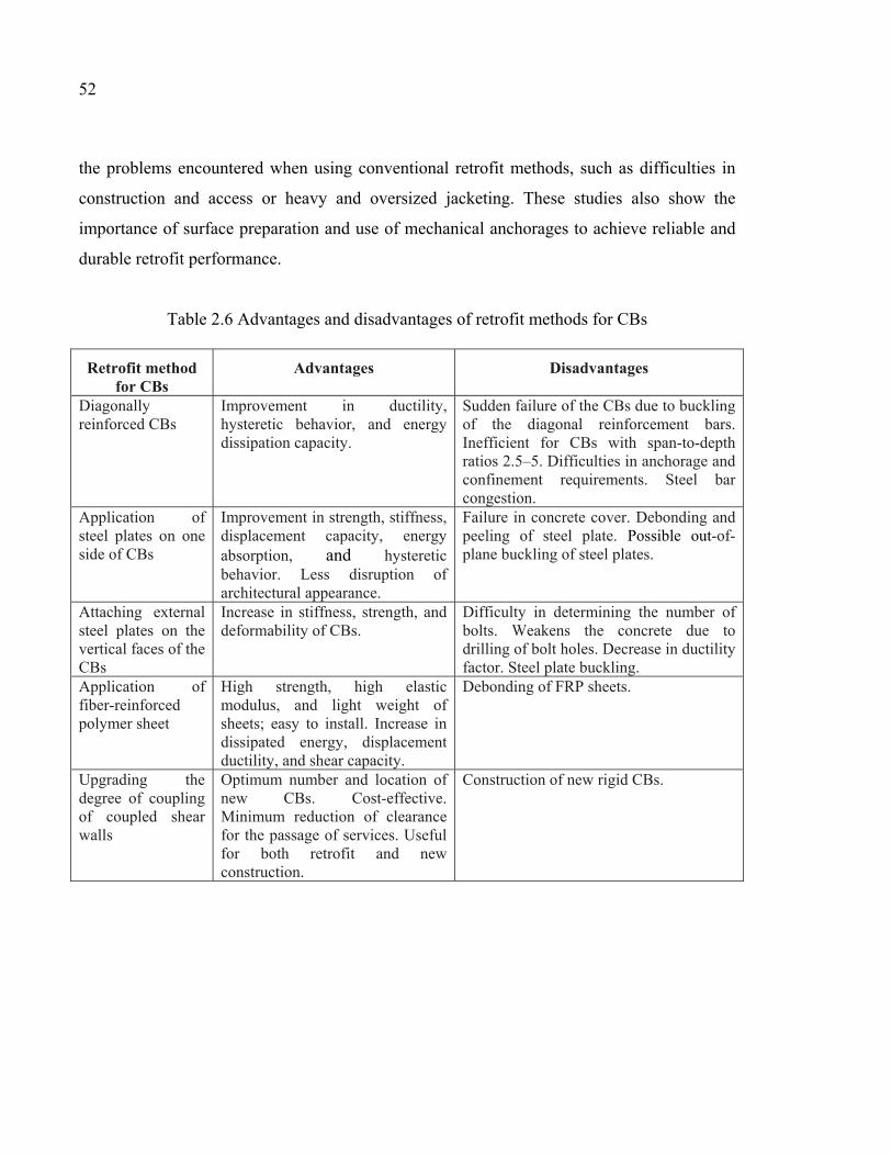
52
the problems encountered when using conventional retrofit methods, such as difficulties in
construction and access or heavy and oversized jacketing. These studies also show the
importance of surface preparation and use of mechanical anchorages to achieve reliable and
durable retrofit performance.
Table 2.6 Advantages and disadvantages of retrofit methods for CBs
Retrofit method for CBs
Advantages Disadvantages
Diagonally reinforced CBs
Improvement in ductility, hysteretic behavior, and energy dissipation capacity.
Sudden failure of the CBs due to buckling of the diagonal reinforcement bars. Inefficient for CBs with span-to-depth ratios 2.5–5. Difficulties in anchorage and confinement requirements. Steel bar congestion.
Application of steel plates on one side of CBs
Improvement in strength, stiffness, displacement capacity, energy absorption, and hysteretic behavior. Less disruption of architectural appearance.
Failure in concrete cover. Debonding and peeling of steel plate. Possible out-of-plane buckling of steel plates.
Attaching external steel plates on the vertical faces of the CBs
Increase in stiffness, strength, and deformability of CBs.
Difficulty in determining the number of bolts. Weakens the concrete due to drilling of bolt holes. Decrease in ductility factor. Steel plate buckling.
Application of fiber-reinforced polymer sheet
High strength, high elastic modulus, and light weight of sheets; easy to install. Increase in dissipated energy, displacement ductility, and shear capacity.
Debonding of FRP sheets.
Upgrading the degree of coupling of coupled shear walls
Optimum number and location of new CBs. Cost-effective. Minimum reduction of clearance for the passage of services. Useful for both retrofit and new construction.
Construction of new rigid CBs.
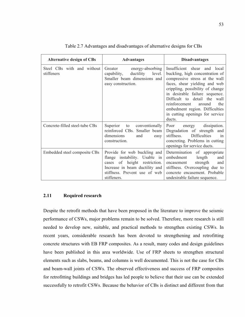
53
Table 2.7 Advantages and disadvantages of alternative designs for CBs
Alternative design of CBs Advantages Disadvantages
Steel CBs with and without stiffeners
Greater energy-absorbing capability, ductility level. Smaller beam dimensions and easy construction.
Insufficient shear and local buckling, high concentration of compressive stress at the wall faces, shear yielding and web crippling, possibility of change in desirable failure sequence. Difficult to detail the wall reinforcement around the embedment region. Difficulties in cutting openings for service ducts.
Concrete-filled steel-tube CBs Superior to conventionally reinforced CBs. Smaller beam dimensions and easy construction.
Poor energy dissipation. Degradation of strength and stiffness. Difficulties in concreting. Problems in cutting openings for service ducts.
Embedded steel composite CBs Provide for web buckling and flange instability. Usable in cases of height restriction. Increase in beam ductility and stiffness. Prevent use of web stiffeners.
Determination of appropriate embedment length and encasement strength and stiffness. Overcoupling due to concrete encasement. Probable undesirable failure sequence.
2.11 Required research
Despite the retrofit methods that have been proposed in the literature to improve the seismic
performance of CSWs, major problems remain to be solved. Therefore, more research is still
needed to develop new, suitable, and practical methods to strengthen existing CSWs. In
recent years, considerable research has been devoted to strengthening and retrofitting
concrete structures with EB FRP composites. As a result, many codes and design guidelines
have been published in this area worldwide. Use of FRP sheets to strengthen structural
elements such as slabs, beams, and columns is well documented. This is not the case for CBs
and beam-wall joints of CSWs. The observed effectiveness and success of FRP composites
for retrofitting buildings and bridges has led people to believe that their use can be extended
successfully to retrofit CSWs. Because the behavior of CBs is distinct and different from that
54
of flexural beams, special attention should be given to investigating and developing an
appropriate, suitable, and effective retrofit method for these special elements. To study the
various parameters involved, including the number of FRP sheet layers, the FRP
configuration, and the effect of mechanical anchorages, more research is needed on this
subject to develop a comprehensive technique for practical application. A number of
important issues related to retrofit of CBs with FRP sheets should also be investigated. The
most salient ones are: (i) identifying the parameters that influence the shear resistance
mechanism of CBs; (ii) proposing retrofit configurations and strategies with EB FRP to
improve the seismic performance of CBs; (iii) studying the effects of FRP sheets and FRP
configurations on the behavior of beam-wall joints; (iv) studying the hysteresis behavior of
CBs retrofitted using EB FRP; and (v) studying the effects of FRP sheets on the ductility,
flexural capacity, and shear capacity of CBs and the failure sequence in CSWs.
2.12 Conclusions
In this study, a literature review of different retrofit methods for CBs in CSWs has been
presented. This important step makes it possible to identify the advantages and drawbacks of
previously developed methods before trying to improve existing methods and develop new
strengthening schemes. An appropriate retrofit method can be selected on the basis of the
probable failure mode, the expected gains in terms of ductility and hysteretic behavior, and
the budget available for the retrofit. However, the exploratory studies performed to
investigate some of these retrofit methods, although useful, clearly remain very few and
exploratory in nature. Therefore, they remain disconnected and fail to translate into sound
approaches that can be used in engineering practice. It follows that more research studies and
experimental investigations are needed to introduce comprehensive and targeted techniques
for practical applications.
CHAPTER 3
EXPERIMENTAL SEISMIC PERFORMANCE EVALUATION OF CBs: COMPARISON OF OLD WITH MODERN CODES
Sara Honarparast a and Omar Chaallal b
a, b Department of Construction Engineering, École de Technologie Supérieure, 1100 Notre-Dame West, Montreal, Quebec, Canada H3C 1K3
Paper accepted in Journal of Earthquake Engineering, July, 2018.
3.1 Abstract
This study presents the results of an experimental investigation on the seismic performance
of two RC CBs for CSWs, one with a conventional reinforcement layout designed according
to the old NBCC 1941 and the other one with a diagonal reinforcement configuration
designed according to modern NBCC 2015 and CSA A23.3 2014 requirements.
Experimental tests were conducted to investigate the behavior of specimens under reversed
cyclic loading. The experimental results reveal that the diagonal reinforcement configuration
could increase the load resisting capacity and energy dissipation capacity by 4.4 times and
10.2 times, respectively. Moreover, the maximum rate of stiffness degradation decreased
from 96% in conventionally reinforced CB to 57% in diagonally reinforced CBs.
Furthermore, diagonal reinforcement layout leaded to more stable hysteretic behavior
without considerable pinching. In contrast and as expected, the conventionally reinforced CB
did not comply with the requirements of the new design code. Therefore, such CBs should be
retrofitted to upgrade their seismic performance in conformity with updated standards
requirements.
3.2 Introduction
Reinforced concrete CSWs with adequate strength and stiffness can be an effective system to
resist lateral forces such as wind and earthquakes. CSWs are generally used for medium-high
56
rise buildings. They resist lateral forces not only through the shear and moment resistance of
their wall segments, but also through the shear action of their CBs. In CSWs, the shear forces
are transferred through the CBs, and the overturning moment is partially resisted by an axial
compression-tension that is coupled across the walls. A properly designed CSW should
ensure that: (i) plastic hinging occurs in the CBs before it does in the walls; (ii) the CBs do
not show major strength or stiffness degradations with load reversal; and (iii) the CBs should
function as the primary energy-dissipation elements by providing stable energy-absorbing
hysteresis loops without pinching. However, designing and detailing CBs with all these
important features were not possible before the 1970s. In Canada, before the first CSA
standard published in 1959, there were some requirements in the NBCC for design of
reinforced-concrete walls, but with no special provision for CSWs or CBs. Design
requirements for CSWs were considered for the first time in the 1984 edition of the CSA
A23.3-M84 standard. However, before publication of the CSA standard, shear walls could be
designed according to the ACI 318 Building Code. Many existing RC buildings with CSW
systems that are located in seismically active zones were designed according to older design
codes without any consideration of or emphasis on ductility requirements. Therefore, such
buildings may have inappropriate seismic performance due to lack of strength, ductility, and
energy dissipation capability, which are crucial features of modern seismic design. The
differences between old and modern seismic design codes can be exemplified by comparing
the minimum lateral earthquake design force at the base according to the NBCC 2010 and the
NBCC 1941 (see Table 3.1). In 1941 the equivalent lateral force was depended to the weight
of the structure and only a factor related to the bearing capacity of soil. There was no seismic
zoning map to differentiate between seismic regions of Canada and hence the amount of
equivalent lateral load at the base of the structure was equal for East and West region of
Canada. This leaded to inaccurate estimation of required design forces. Furthermore, there
was no consideration for very important parameters such as factors accounting for the
importance of structures, the ductility, the over-strength, and effects of higher vibration
modes. However, from 1941 to present, significant changes were implemented to achieve a
better estimation of equivalent static design base shear. Seismic zoning maps were developed
and some modification factors were considered for structural ductility, soil and construction
57
types, higher mode effects, and over-strength. These changes provided more accuracy in the
determination of design forces and their distribution along the height of the structure. It was
found that, given a typical building with CSWs, the total base shear calculated using NBCC
2010 can be much greater than that obtained when designing according to NBCC 1941.
Furthermore, buildings designed according to old codes have insufficient flexural capacity
above the plastic hinge region and inadequate shear strength over their height (Mitchell et al.,
2010).
Another problem associated with old CBs is related to their conventional reinforcement
layout, which features top and bottom longitudinal bars to resist flexure and vertical ties or
stirrups distributed along the length to provide shear resistance. Studies carried out by Paulay
(1969) and others (Binney, 1972; Paulay, 1974; Santhakumar, 1974; Shiu et al., 1978) on the
behavior and performance of CSWs and CBs revealed the benefit of using diagonal
reinforcement in the CBs and opened a whole new era worldwide for design of CBs with
diagonal reinforcement. The diagonal reinforcements extend through the entire CB and are
anchored into the walls, providing thereby both flexural and shear resistance. This
arrangement is now part of most modern international seismic design codes and guidelines.
Further studies (Harries, 1995; Tassios et al., 1996; Galano & Vignoli, 2000; Kwan & Zhao,
2002; Lu & Chen, 2005; Yun et al., 2008; Naish et al., 2013; Lim et al., 2016) were
conducted to investigate the effect of different reinforcement layouts and their modeling on
the seismic performance of CBs. Note that CBs with conventional reinforcement are allowed
by CSA A23.3-14, but only if the shear stress resulting from factored loads is small, i.e., less
than cu fdl ′)/(1.0 , where lu is the clear span, d the effective depth, and cf ′ the concrete
compressive strength.
In the research studies mentioned above, the specimens with either conventional
reinforcement or diagonal layouts were designed according to the provisions for design of
CSWs in the last available code in that study year and not according to old designed codes. It
means that in each of these studies, the specimens were designed according to one specific
design code, with no attempt to compare with older ones regarding seismic performance of
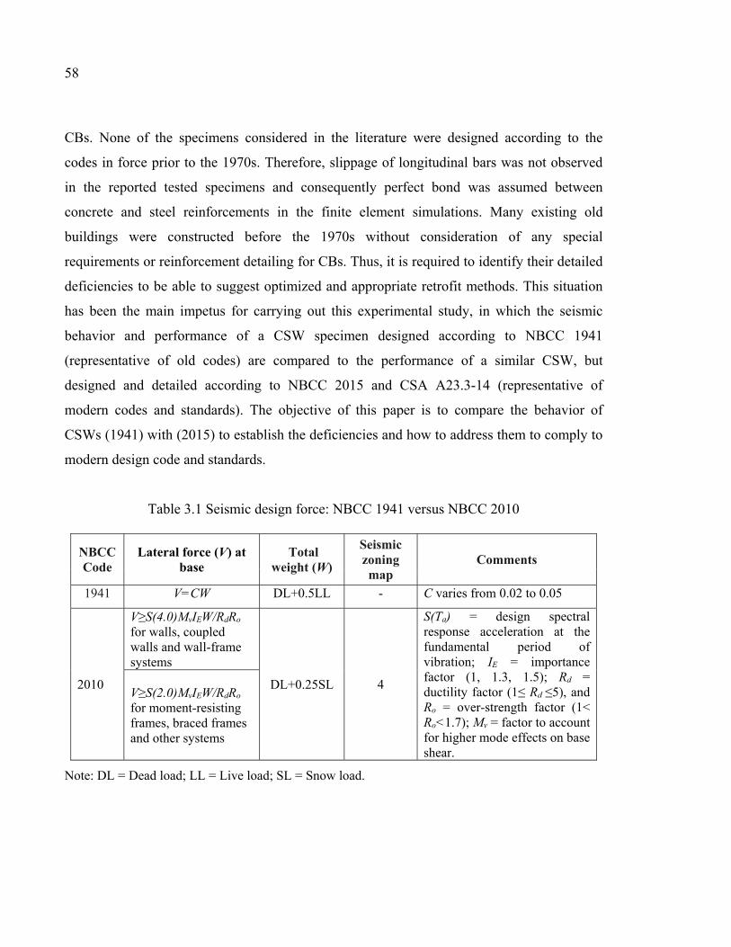
58
CBs. None of the specimens considered in the literature were designed according to the
codes in force prior to the 1970s. Therefore, slippage of longitudinal bars was not observed
in the reported tested specimens and consequently perfect bond was assumed between
concrete and steel reinforcements in the finite element simulations. Many existing old
buildings were constructed before the 1970s without consideration of any special
requirements or reinforcement detailing for CBs. Thus, it is required to identify their detailed
deficiencies to be able to suggest optimized and appropriate retrofit methods. This situation
has been the main impetus for carrying out this experimental study, in which the seismic
behavior and performance of a CSW specimen designed according to NBCC 1941
(representative of old codes) are compared to the performance of a similar CSW, but
designed and detailed according to NBCC 2015 and CSA A23.3-14 (representative of
modern codes and standards). The objective of this paper is to compare the behavior of
CSWs (1941) with (2015) to establish the deficiencies and how to address them to comply to
modern design code and standards.
Table 3.1 Seismic design force: NBCC 1941 versus NBCC 2010
NBCC Code
Lateral force (V) at base
Total weight (W)
Seismic zoning map
Comments
1941 V=CW DL+0.5LL - C varies from 0.02 to 0.05
2010
V≥S(4.0)MvIEW/RdRo for walls, coupled walls and wall-frame systems
DL+0.25SL 4
S(Ta) = design spectral response acceleration at the fundamental period of vibration; IE = importance factor (1, 1.3, 1.5); Rd = ductility factor (1≤ Rd ≤5), and Ro = over-strength factor (1< Ro<1.7); Mv = factor to account for higher mode effects on base shear.
V≥S(2.0)MvIEW/RdRo
for moment-resisting frames, braced frames and other systems
Note: DL = Dead load; LL = Live load; SL = Snow load.
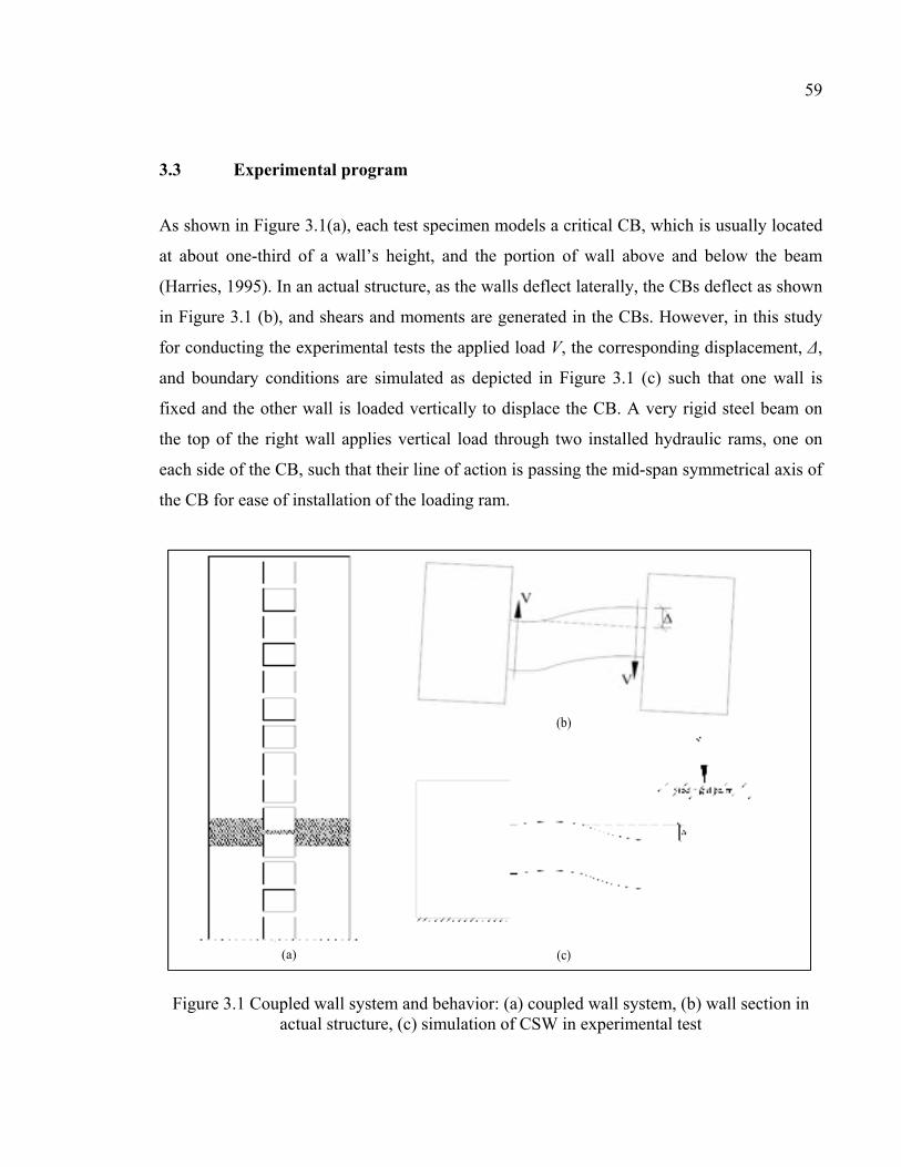
59
3.3 Experimental program
As shown in Figure 3.1(a), each test specimen models a critical CB, which is usually located
at about one-third of a wall’s height, and the portion of wall above and below the beam
(Harries, 1995). In an actual structure, as the walls deflect laterally, the CBs deflect as shown
in Figure 3.1 (b), and shears and moments are generated in the CBs. However, in this study
for conducting the experimental tests the applied load V, the corresponding displacement, Δ,
and boundary conditions are simulated as depicted in Figure 3.1 (c) such that one wall is
fixed and the other wall is loaded vertically to displace the CB. A very rigid steel beam on
the top of the right wall applies vertical load through two installed hydraulic rams, one on
each side of the CB, such that their line of action is passing the mid-span symmetrical axis of
the CB for ease of installation of the loading ram.
Figure 3.1 Coupled wall system and behavior: (a) coupled wall system, (b) wall section in actual structure, (c) simulation of CSW in experimental test
(b)
(c) (a)
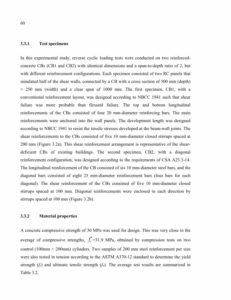
60
3.3.1 Test specimens
In this experimental study, reverse cyclic loading tests were conducted on two reinforced-
concrete CBs (CB1 and CB2) with identical dimensions and a span-to-depth ratio of 2, but
with different reinforcement configurations. Each specimen consisted of two RC panels that
simulated half of the shear walls, connected by a CB with a cross section of 500 mm (depth)
× 250 mm (width) and a clear span of 1000 mm. The first specimen, CB1, with a
conventional reinforcement layout, was designed according to NBCC 1941 such that shear
failure was more probable than flexural failure. The top and bottom longitudinal
reinforcements of the CBs consisted of four 20 mm-diameter reinforcing bars. The main
reinforcements were anchored into the wall panels. The development length was designed
according to NBCC 1941 to resist the tensile stresses developed at the beam-wall joints. The
shear reinforcements to the CBs consisted of five 10 mm-diameter closed stirrups spaced at
200 mm (Figure 3.2a). This shear reinforcement arrangement is representative of the shear-
deficient CBs of existing buildings. The second specimen, CB2, with a diagonal
reinforcement configuration, was designed according to the requirements of CSA A23.3-14.
The longitudinal reinforcement of the CB consisted of six 10 mm-diameter steel bars, and the
diagonal bars consisted of eight 25 mm-diameter reinforcement bars (four bars for each
diagonal). The shear reinforcement of the CBs consisted of five 10 mm-diameter closed
stirrups spaced at 100 mm. Diagonal reinforcements were enclosed in each direction by
stirrups spaced at 100 mm (Figure 3.2b).
3.3.2 Material properties
A concrete compressive strength of 30 MPa was used for design. This was very close to the
average of compressive strengths, cf ′=31.9 MPa, obtained by compression tests on two
control (100mm × 200mm) cylinders. Two samples of 200 mm steel reinforcement per size
were also tested in tension according to the ASTM A370-12 standard to determine the yield
strength (fy) and ultimate tensile strength (fu). The average test results are summarized in
Table 3.2.
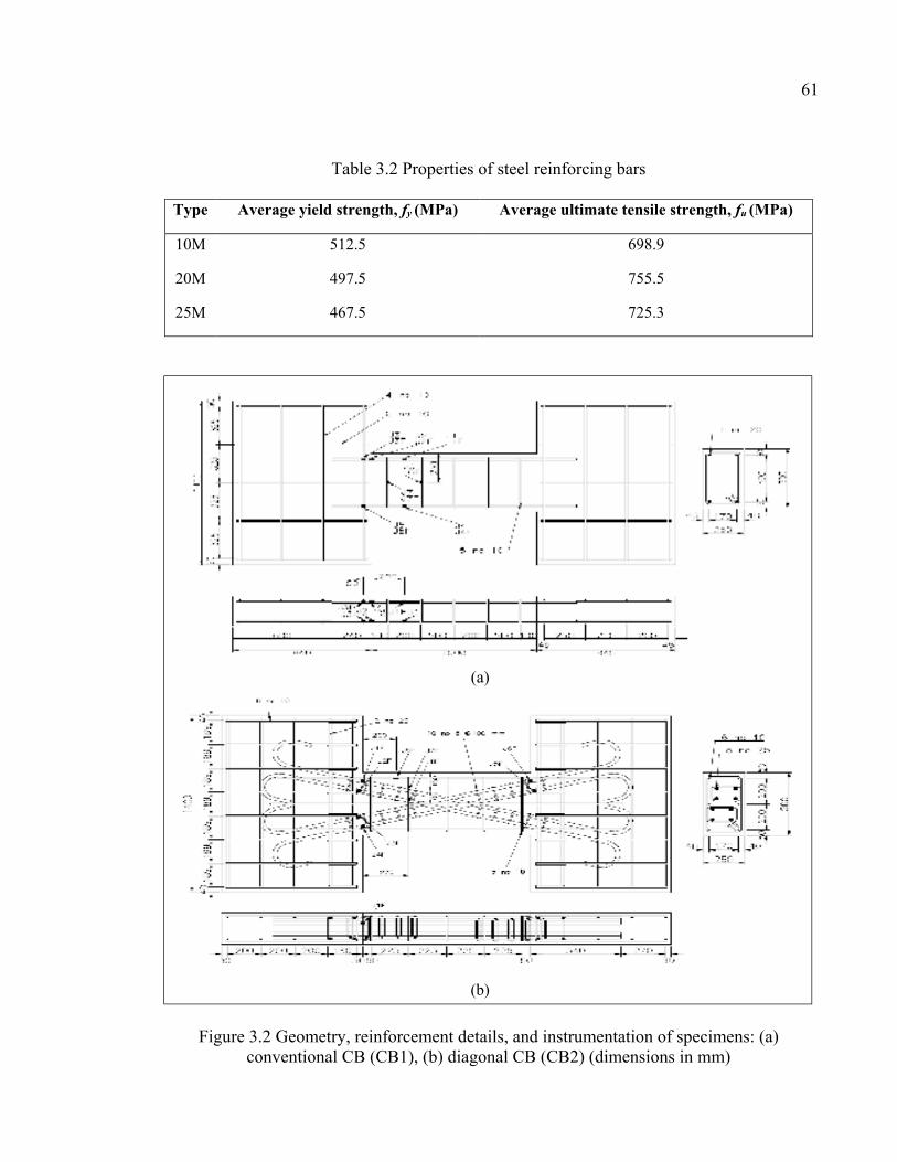
61
Table 3.2 Properties of steel reinforcing bars
Type Average yield strength, fy (MPa) Average ultimate tensile strength, fu (MPa)
10M
20M
25M
512.5
497.5
467.5
698.9
755.5
725.3
Figure 3.2 Geometry, reinforcement details, and instrumentation of specimens: (a) conventional CB (CB1), (b) diagonal CB (CB2) (dimensions in mm)
(a)
(b)
62
3.3.3 Instrumentation
A large number of strain gauges were installed to monitor strain variations in the steel
reinforcements with load and hence to define their stress-strain curve. The layout of the strain
gauges is illustrated in Figure 3.2 The strain gauges were glued onto the longitudinal and
diagonal steel reinforcing bars especially near the critical location of CB-wall joints. The
gauges were attached at the front and back sides, at the top and bottom of the CBs to obtain
the strain magnitude in different locations and monitor steel yielding as the loading is
applied. A few strain gauges were also attached to the stirrups for monitoring their behavior
along the test. Additionally, as illustrated in Figure 3.3 (test setup) some LVDTs were
installed in different zones to measure the vertical displacement as well as out of plane
displacement of the loaded wall (L1 and L2), and to check the change of distance between
the two walls (L3, L4). Two more sensors were glued to the middle of each wall to check the
wall’s rotation (R1, R2).
3.3.4 Test setup and loading procedure
Figure 3.3 illustrates the experimental setup and the loading and boundary conditions of the
coupled shear-wall specimens. The left wall was fixed to the reaction floor of the laboratory,
and the load was applied vertically to the right wall through the loading beam on top. In order
to model the actual coupled wall system, the centroid axes of walls should be maintained
parallel during the test. Therefore, a single hydraulic ram was installed next to the loaded
wall to keep the walls parallel as well as providing forces to balance the dead load. Upward
and downward loading was applied by two 500 kN hydraulic rams, one on each side of the
CB, their line of action being the midspan symmetrical axis of the CB. The walls were also
restrained from out-of-plane displacements.
The specimens were tested under reverse cyclic loading under displacement-control
conditions, as shown in Figure 3.4 Two load cycles were applied at a rate of 3 mm/min at
each displacement’s amplitude, which was set equal to 0.5, 1, 2, 3, … times the value of the
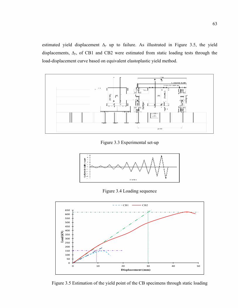
63
estimated yield displacement ∆y up to failure. As illustrated in Figure 3.5, the yield
displacements, ∆y, of CB1 and CB2 were estimated from static loading tests through the
load-displacement curve based on equivalent elastoplastic yield method.
Figure 3.3 Experimental set-up
Figure 3.4 Loading sequence
Figure 3.5 Estimation of the yield point of the CB specimens through static loading
0
50
100
150
200
250
300
350
400
450
500
550
600
650
0 10 20 30 40 50
Load
(kN)
Displacement (mm)
CB1 CB2
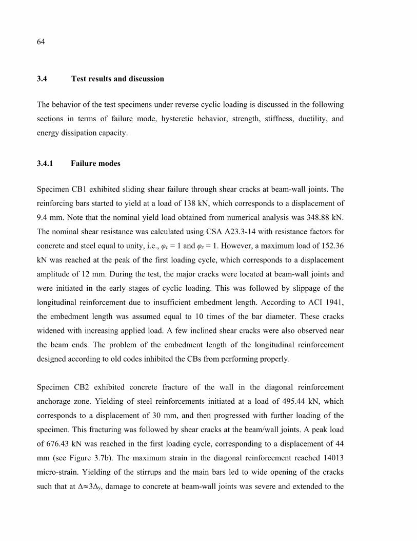
64
3.4 Test results and discussion
The behavior of the test specimens under reverse cyclic loading is discussed in the following
sections in terms of failure mode, hysteretic behavior, strength, stiffness, ductility, and
energy dissipation capacity.
3.4.1 Failure modes
Specimen CB1 exhibited sliding shear failure through shear cracks at beam-wall joints. The
reinforcing bars started to yield at a load of 138 kN, which corresponds to a displacement of
9.4 mm. Note that the nominal yield load obtained from numerical analysis was 348.88 kN.
The nominal shear resistance was calculated using CSA A23.3-14 with resistance factors for
concrete and steel equal to unity, i.e., φc = 1 and φs = 1. However, a maximum load of 152.36
kN was reached at the peak of the first loading cycle, which corresponds to a displacement
amplitude of 12 mm. During the test, the major cracks were located at beam-wall joints and
were initiated in the early stages of cyclic loading. This was followed by slippage of the
longitudinal reinforcement due to insufficient embedment length. According to ACI 1941,
the embedment length was assumed equal to 10 times of the bar diameter. These cracks
widened with increasing applied load. A few inclined shear cracks were also observed near
the beam ends. The problem of the embedment length of the longitudinal reinforcement
designed according to old codes inhibited the CBs from performing properly.
Specimen CB2 exhibited concrete fracture of the wall in the diagonal reinforcement
anchorage zone. Yielding of steel reinforcements initiated at a load of 495.44 kN, which
corresponds to a displacement of 30 mm, and then progressed with further loading of the
specimen. This fracturing was followed by shear cracks at the beam/wall joints. A peak load
of 676.43 kN was reached in the first loading cycle, corresponding to a displacement of 44
mm (see Figure 3.7b). The maximum strain in the diagonal reinforcement reached 14013
micro-strain. Yielding of the stirrups and the main bars led to wide opening of the cracks
such that at ∆≈3∆y, damage to concrete at beam-wall joints was severe and extended to the
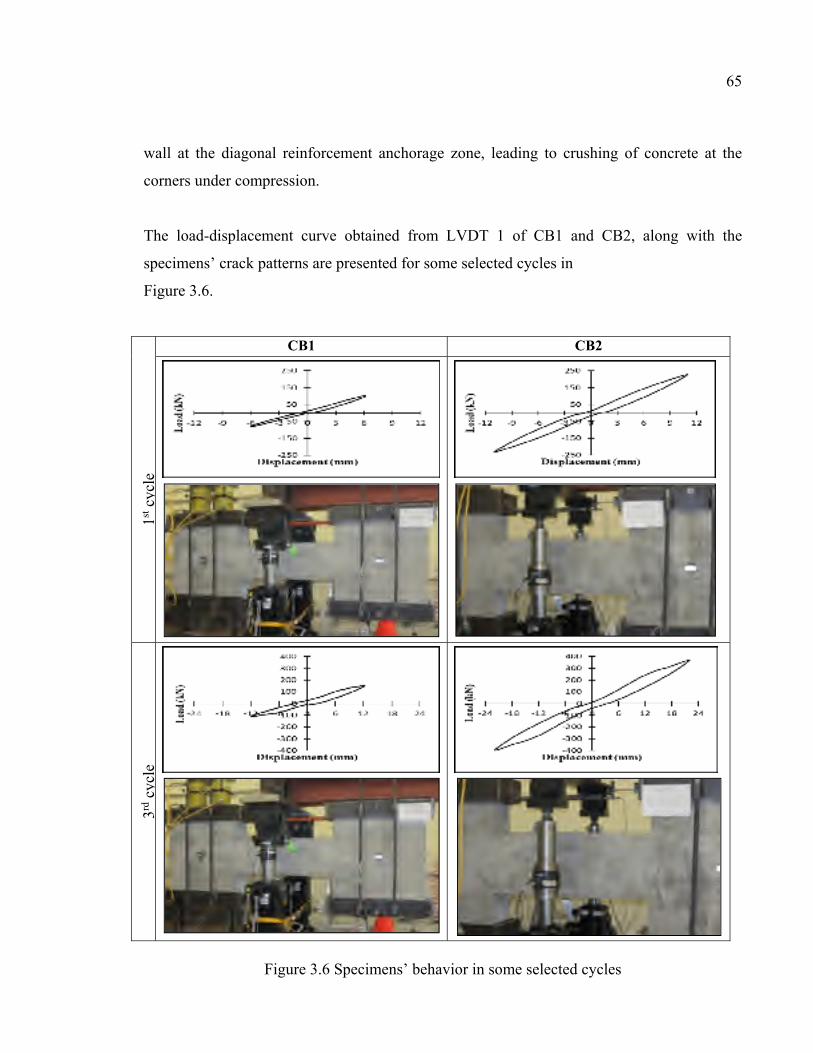
65
wall at the diagonal reinforcement anchorage zone, leading to crushing of concrete at the
corners under compression.
The load-displacement curve obtained from LVDT 1 of CB1 and CB2, along with the
specimens’ crack patterns are presented for some selected cycles in
Figure 3.6.
CB1 CB2
1st c
ycle
3rd c
ycle
Figure 3.6 Specimens’ behavior in some selected cycles
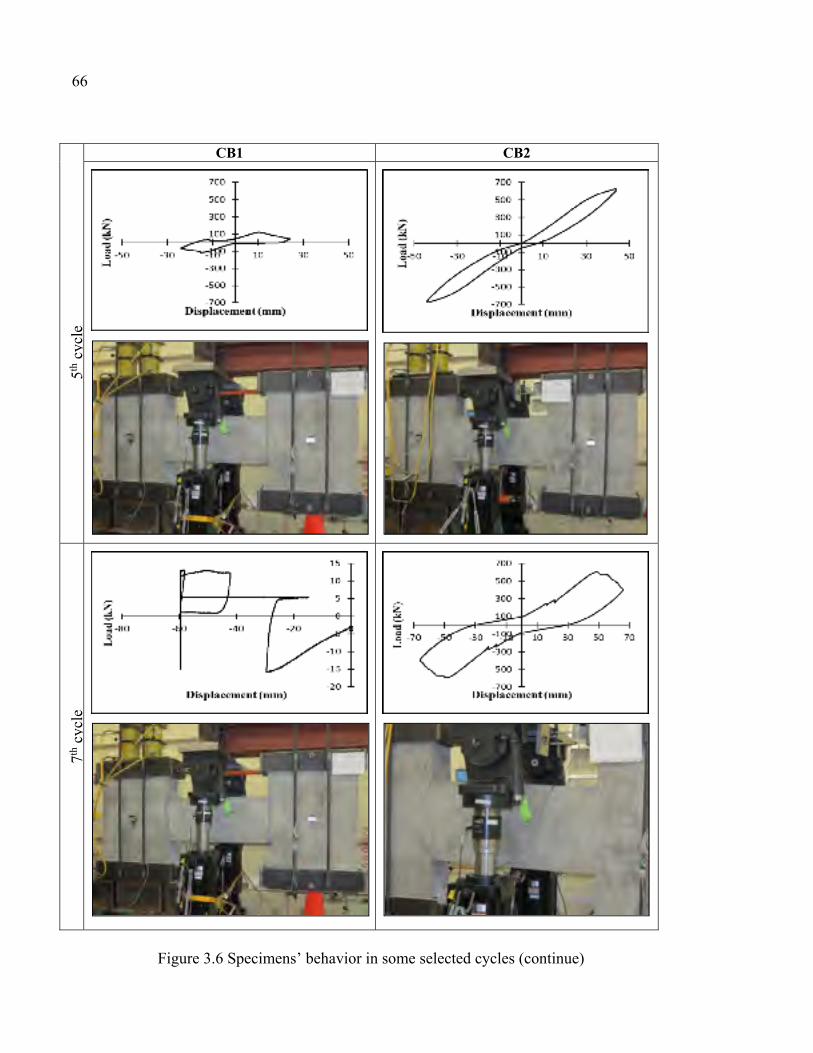
66 CB1 CB2
5th c
ycle
7th c
ycle
Figure 3.6 Specimens’ behavior in some selected cycles (continue)
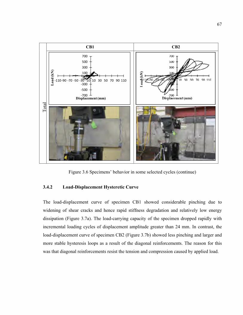
67
CB1 CB2 T
otal
Figure 3.6 Specimens’ behavior in some selected cycles (continue)
3.4.2 Load-Displacement Hysteretic Curve
The load-displacement curve of specimen CB1 showed considerable pinching due to
widening of shear cracks and hence rapid stiffness degradation and relatively low energy
dissipation (Figure 3.7a). The load-carrying capacity of the specimen dropped rapidly with
incremental loading cycles of displacement amplitude greater than 24 mm. In contrast, the
load-displacement curve of specimen CB2 (Figure 3.7b) showed less pinching and larger and
more stable hysteresis loops as a result of the diagonal reinforcements. The reason for this
was that diagonal reinforcements resist the tension and compression caused by applied load.
-700-500-300-100100300500700
-110-90 -70 -50 -30 -10 10 30 50 70 90 110
Loa
d (k
N)
Displacement (mm)
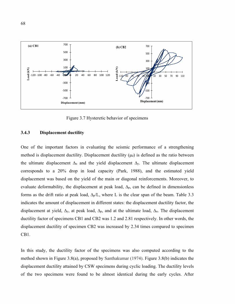
68
Figure 3.7 Hysteretic behavior of specimens
3.4.3 Displacement ductility
One of the important factors in evaluating the seismic performance of a strengthening
method is displacement ductility. Displacement ductility (μd) is defined as the ratio between
the ultimate displacement ∆u and the yield displacement ∆y. The ultimate displacement
corresponds to a 20% drop in load capacity (Park, 1988), and the estimated yield
displacement was based on the yield of the main or diagonal reinforcements. Moreover, to
evaluate deformability, the displacement at peak load, ∆p, can be defined in dimensionless
forms as the drift ratio at peak load, ∆p/L, where L is the clear span of the beam. Table 3.3
indicates the amount of displacement in different states: the displacement ductility factor, the
displacement at yield, ∆y, at peak load, ∆p, and at the ultimate load, ∆u. The displacement
ductility factor of specimens CB1 and CB2 was 1.2 and 2.81 respectively. In other words, the
displacement ductility of specimen CB2 was increased by 2.34 times compared to specimen
CB1.
In this study, the ductility factor of the specimens was also computed according to the
method shown in Figure 3.8(a), proposed by Santhakumar (1974). Figure 3.8(b) indicates the
displacement ductility attained by CSW specimens during cyclic loading. The ductility levels
of the two specimens were found to be almost identical during the early cycles. After
-700
-500
-300
-100
100
300
500
700
-120 -100 -80 -60 -40 -20 0 20 40 60 80 100 120
Loa
d (k
N)
Displacement (mm)
(a) CB1
-700
-500
-300
-100
100
300
500
700
-110 -90 -70 -50 -30 -10 10 30 50 70 90 110
Lo
ad
(k
N)
Displacement (mm)
(b) CB2
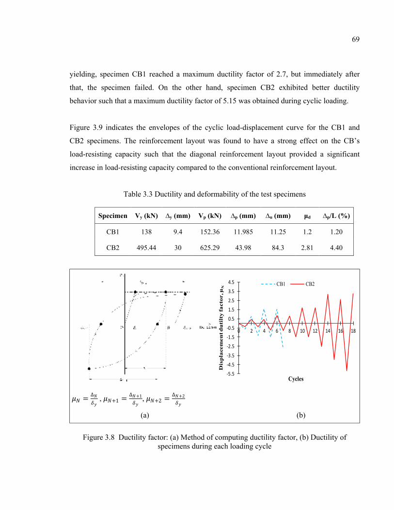
69
yielding, specimen CB1 reached a maximum ductility factor of 2.7, but immediately after
that, the specimen failed. On the other hand, specimen CB2 exhibited better ductility
behavior such that a maximum ductility factor of 5.15 was obtained during cyclic loading.
Figure 3.9 indicates the envelopes of the cyclic load-displacement curve for the CB1 and
CB2 specimens. The reinforcement layout was found to have a strong effect on the CB’s
load-resisting capacity such that the diagonal reinforcement layout provided a significant
increase in load-resisting capacity compared to the conventional reinforcement layout.
Table 3.3 Ductility and deformability of the test specimens
Specimen Vy (kN) ∆y (mm) Vp (kN) ∆p (mm) ∆u (mm) μd ∆p/L (%)
CB1 138 9.4 152.36 11.985 11.25 1.2 1.20
CB2 495.44 30 625.29 43.98 84.3 2.81 4.40
Figure 3.8 Ductility factor: (a) Method of computing ductility factor, (b) Ductility of specimens during each loading cycle
-5.5
-4.5
-3.5
-2.5
-1.5
-0.5
0.5
1.5
2.5
3.5
4.5
0 2 4 6 8 10 12 14 16 18
Dis
pla
cem
ent d
uti
lty f
act
or,
µN
Cycles
CB1 CB2
= ∆ , +1 = ∆ +1, +2 = ∆ +2
(a) (b)
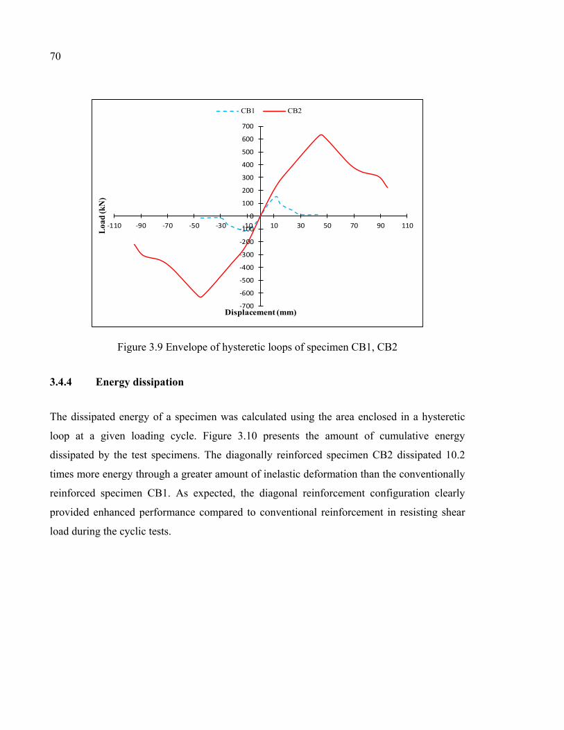
70
Figure 3.9 Envelope of hysteretic loops of specimen CB1, CB2
3.4.4 Energy dissipation
The dissipated energy of a specimen was calculated using the area enclosed in a hysteretic
loop at a given loading cycle. Figure 3.10 presents the amount of cumulative energy
dissipated by the test specimens. The diagonally reinforced specimen CB2 dissipated 10.2
times more energy through a greater amount of inelastic deformation than the conventionally
reinforced specimen CB1. As expected, the diagonal reinforcement configuration clearly
provided enhanced performance compared to conventional reinforcement in resisting shear
load during the cyclic tests.
-700
-600
-500
-400
-300
-200
-100
0
100
200
300
400
500
600
700
-110 -90 -70 -50 -30 -10 10 30 50 70 90 110
Loa
d (k
N)
Displacement (mm)
CB1 CB2
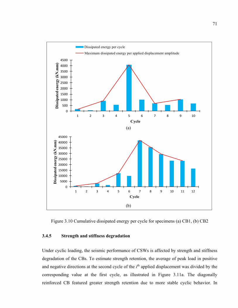
71
Figure 3.10 Cumulative dissipated energy per cycle for specimens (a) CB1, (b) CB2
3.4.5 Strength and stiffness degradation
Under cyclic loading, the seismic performance of CSWs is affected by strength and stiffness
degradation of the CBs. To estimate strength retention, the average of peak load in positive
and negative directions at the second cycle of the ith applied displacement was divided by the
corresponding value at the first cycle, as illustrated in Figure 3.11a. The diagonally
reinforced CB featured greater strength retention due to more stable cyclic behavior. In
0
500
1000
1500
2000
2500
3000
3500
4000
4500
1 2 3 4 5 6 7 8 9 10
Dis
sipa
ted
ener
gy (k
N.m
m)
Cycle
Dissipated energy per cycle
Maximum dissipated energy per applied displacement amplitude
0
5000
10000
15000
20000
25000
30000
35000
40000
45000
1 2 3 4 5 6 7 8 9 10 11 12
Dis
sipa
ted
ener
gy (k
N.m
m)
Cycle
(a)
(b)
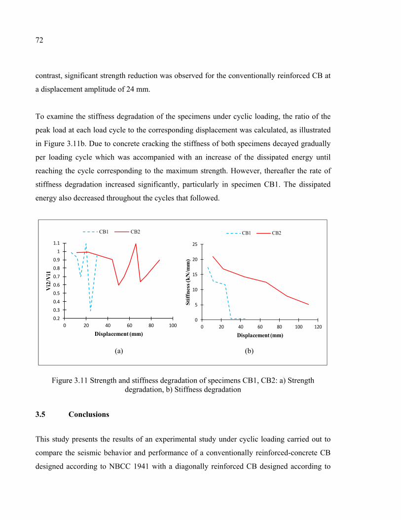
72
contrast, significant strength reduction was observed for the conventionally reinforced CB at
a displacement amplitude of 24 mm.
To examine the stiffness degradation of the specimens under cyclic loading, the ratio of the
peak load at each load cycle to the corresponding displacement was calculated, as illustrated
in Figure 3.11b. Due to concrete cracking the stiffness of both specimens decayed gradually
per loading cycle which was accompanied with an increase of the dissipated energy until
reaching the cycle corresponding to the maximum strength. However, thereafter the rate of
stiffness degradation increased significantly, particularly in specimen CB1. The dissipated
energy also decreased throughout the cycles that followed.
Figure 3.11 Strength and stiffness degradation of specimens CB1, CB2: a) Strength degradation, b) Stiffness degradation
3.5 Conclusions
This study presents the results of an experimental study under cyclic loading carried out to
compare the seismic behavior and performance of a conventionally reinforced-concrete CB
designed according to NBCC 1941 with a diagonally reinforced CB designed according to
0.20.30.40.50.60.70.80.9
11.1
0 20 40 60 80 100
Vi2
/Vi1
Displacement (mm)
CB1 CB2
0
5
10
15
20
25
0 20 40 60 80 100 120
Sti
ffn
ess
(kN
/mm
)
Displacement (mm)
CB1 CB2
(a) (b)
73
NBCC 2015 and CSA/A23.3 2014. Based on analysis of the test results summarized in Table
3.4, the following conclusions can be drawn:
a) The diagonal reinforcement configuration can improve the load-resisting capacity,
deformability, strength, ductility, and energy dissipation capacity of a specimen and can
lead to a less brittle failure mode.
b) Specimen CB1, designed with old codes, failed prematurely due to brittle sliding shear
failure. Specimen CB2, designed with modern codes, failed by concrete crushing after
yielding of steel.
c) Significant pinching was observed in the hysteretic behavior of the conventionally
reinforced CB. This contrasts with the diagonally reinforced CB, which featured a larger
and more stable hysteretic load-displacement curve and dissipated 10.2 times more
energy.
d) The conventionally reinforced CB specimen exhibited low ductility, but the displacement
ductility factor of the diagonally reinforced CB reached a value of 2.81. The ultimate drift
ratio achieved by the diagonally reinforced CB was high, thereby providing reasonable
deformability during earthquake events.
e) The conventionally reinforced CB showed considerable strength and stiffness
degradations. This contrasts with the diagonally reinforced CB, which offered greater
strength retention due to more stable cyclic behavior.
f) The weak performance of the conventionally reinforced CB indicates that retrofitting of
existing CSWs designed to old codes and located in seismic region is inevitable. This
confirms the conclusions reached by other studies that suggested that appropriate retrofit
methods be provided to improve the seismic performance of conventionally reinforced
CBs.
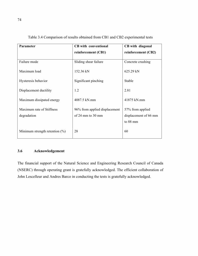
74
Table 3.4 Comparison of results obtained from CB1 and CB2 experimental tests Parameter CB with conventional
reinforcement (CB1)
CB with diagonal
reinforcement (CB2)
Failure mode Sliding shear failure Concrete crushing
Maximum load 152.36 kN 625.29 kN
Hysteresis behavior Significant pinching Stable
Displacement ductility 1.2 2.81
Maximum dissipated energy 4087.5 kN.mm 41875 kN.mm
Maximum rate of Stiffness
degradation
96% from applied displacement
of 24 mm to 30 mm
57% from applied
displacement of 66 mm
to 88 mm
Minimum strength retention (%) 28 60
3.6 Acknowledgement
The financial support of the Natural Science and Engineering Research Council of Canada
(NSERC) through operating grant is gratefully acknowledged. The efficient collaboration of
John Lescelleur and Andres Barco in conducting the tests is gratefully acknowledged.
CHAPTER 4
EXTERNALLY BONDED CFRP COMPOSITES FOR SEISMIC RETROFIT OF RC CBS DESIGNED ACCORDING TO OLD CODES
Sara Honarparast a, Georges El-Saikaly b and Omar Chaallal c, F.ASCE
a, b, c Department of Construction Engineering, École de Technologie Supérieure,
1100 Notre-Dame West, Montreal, Quebec, Canada H3C 1K3
Paper accepted in Journal of Advances in Structural Engineering, May, 2018.
4.1 Abstract
A large number of existing buildings have seismic-resistant systems designed according to
old code provisions. These structural systems exhibit non-ductile behavior and can present a
significant risk in the case of a moderate or significant seismic event. RC CSWs designed to
old codes and standards are among those deficient structures that need to be seismically
upgraded. This paper aims to investigate a new retrofitting and upgrading method using EB-
CFRP composites for existing or/and damaged RC CBs that can improve the seismic
performance of them during earthquakes. To this end, an experimental test was conducted to
evaluate the seismic behavior of two identical RC CSW specimens under reverse cyclic
loading. To simulate the old existing building, the specimens were designed and constructed
according to the old NBCC 1941 with a conventionally reinforced CB. One of the specimens
was tested as a control, and the other was strengthened using EB-CFRP composites to
evaluate the improvement in its seismic performance. Results show that the retrofit method
using EB-CFRP resulted in significant enhancement in strength and energy dissipation
capacity compared to the conventionally reinforced CB from the control specimen. In
addition, EB-CFRP sheets resulted in much improved hysteretic and ductile behavior and in
lesser strength and stiffness degradation.
76
4.2 Introduction
Reinforced concrete CSWs with adequate strength and stiffness have proven to be an
effective system for resisting lateral forces in medium-high rise buildings. In this system, the
lateral forces are resisted, not only through the shear and moment resistance of the wall
segments, but also through the action of the CBs. In CSWs, the shear forces are transferred
through the CBs, and the overturning moment is partially resisted by an axial compression-
tension that is coupled across the walls. In well-designed CSWs, plastic hinges form in the
CBs before the walls. This means that CBs are the primary energy-dissipation elements by
featuring stable energy-absorbing hysteresis loops without pinching. However, achieving
these fundamental sequential features was not feasible through the requirements of design
codes before the 1970s. This implies that in the case of a major seismic event, many existing
RC buildings with CSW systems designed according to old codes are prone to collapse due
to lack of sufficient strength, ductility, and energy dissipation capacity. These features are of
prime importance in modern seismic design codes.
Taking advantages of recent progress and innovations in seismic design methodologies, the
performance and seismic behavior of RC buildings designed according to modern codes have
been greatly improved. This is not true for existing RC buildings designed before the 1970s.
For CSWs, for example, the CBs were designed and built with a conventional reinforcement
layout in which top and bottom longitudinal bars resist flexure and distributed vertical ties or
stirrups provide shear strength. Therefore, these CBs behave in a non-ductile manner and
exhibit either diagonal tension failure or sliding shear failure at the beam-wall joints (Kwan
& Zhao, 2002). The pioneering work led by Paulay (1969) and others (Binney, 1972; Paulay,
1974; Santhakumar, 1974; Shiu et al., 1978) on the subject of CSWs and CBs opened up a
whole new era for the design of CBs with diagonal reinforcement. Due to the satisfactory
behavior of diagonally reinforced CBs under cyclic loading, such CBs are now part of most
modern seismic design codes. The diagonal reinforcements extend through the entire CB and
provide both flexural and shear resistance. Extending diagonal reinforcement beyond the
beam ends improves hysteretic behavior by preventing sliding shear as well as spreading the
77
hinging regions away from the wall face (Paulay, 1974). The effects of different
reinforcement configurations on the seismic behavior of CBs have been further investigated
more recently (Tassios et al., 1996; Galano & Vignoli, 2000; Kwan & Zhao, 2002; Yun et al.,
2008; Naish et al., 2013; Lim et al., 2016).
In Canada, before the first Canadian Standards (CSA, 1959), there were only some
requirements in the NBCC for the design of RC walls, but with no special provisions for
CSWs or CBs. Design requirements for CSWs were considered for the first time in the 1984
edition of the CSA A23.3-M84 standard. Prior to the CSA A23.3-M84 (1984) standard, all
CBs were designed and constructed with conventionally reinforcement layout and the
concept of diagonally reinforced CB was not yet adopted in practice. In contrast, the new
Canadian standards provide provisions to design new CSWs and distinguish between two
types (conventional or diagonal configuration) of CBs depending on the shear stress level
resulting from the factored loads. A conventional reinforcement layout can be used for CBs
only if the shear stress resulting from the factored load effect is less than cu fdl ′)/(1.0 ,
where lu is the clear span, d the effective depth, and cf ′ the concrete compressive strength.
However, for seismic loading most CBs fall into the diagonal reinforcement category.
According to ACI 1941 code, the embedment length of longitudinal steel reinforcements into
the walls was equal to 10 times the longitudinal bar diameter. The longitudinal bars were
anchored with a very short length into the walls. While, in the new seismic design method,
diagonal reinforcements must be extended into the walls with an embedment length of at
least 1.5ld, where ld is calculated through the specified equation in CSA A23.3-14. This
embedment length is substantially greater than 10 times the longitudinal bar diameter.
In the old design codes, the beam transverse reinforcement was designed to resist only the
shear resulted from code-specified lateral forces and not the shear corresponding to the
development of beam flexural plastic hinges as in modern codes (capacity design). Hence,
compared to new standards, design to old standards resulted in less transverse steel
reinforcements widely spaced. In contrast, according to the modern codes requirements for
78
design of diagonally reinforced CBs, diagonal reinforcements must have closely spaced
hoops with a maximum spacing equal to the smallest of: 6 times of diagonal bar diameter, 24
times of ties’ diameter and 100 mm.
In modern seismic design codes, some design and detailing requirements linked to the
ductility-related factor Rd, the overstrength-related factor Ro, and the estimation of inelastic
rotational capacity of walls and CBs are specified and provided. In order to achieve ductile
CSWs, the CBs should behave in a ductile manner. Ductile CBs shall have a depth not
greater than twice the clear span of the beam. Furthermore, to ensure ductility of the coupled
systems, the inelastic rotational capacity of both the walls and the CBs shall be greater than
their respective inelastic rotational demands. The inelastic rotational capacity of CBs, θic,
shall be taken as 0.04 and 0.02 for diagonally reinforced and conventionally reinforced CBs
respectively. In contrast, in the old seismic design procedures, such provisions were not
specified, nor required.
Regarding the mentioned requirements for ductile CBs, it has been concluded that the CBs
built before the adoption of modern seismic codes will exhibit inappropriate seismic
behavior. Stirrups that are too widely spaced, poor confinement of boundary regions,
inadequate lap splices in longitudinal reinforcement, short embedment length of longitudinal
reinforcements into the walls, and ineffective reinforcement layout in CBs are among the
deficiencies often observed.
For seismic compliance of CBs to modern codes, retrofitting and strengthening the
seismically deficient RC CBs rather than replacing them is generally more cost-effective and
will cause less disruption and interference.
Over the last two decades, several seismic strengthening methods and rehabilitation
techniques have been developed to improve the seismic performance of existing CSWs,
especially their CBs. The proposed retrofit procedures for CBs include bonding steel plates to
one side of the CB (Harries, 1995), upgrading the degree of coupling by adding an optimized
79
number of deep CBs (Chaallal & Nollet, 1997), and bolting steel plates onto the side faces of
the CBs with or without adding a buckling restraint device to control plate buckling (Su &
Zhu, 2005; Su & Cheng, 2011; Cheng et al., 2018).
Furthermore, some alternative designs for CBs have been proposed in recent decades. They
include steel CBs with and without stiffeners (Harries, 1995), concrete-filled steel tube CBs
(Teng et al., 1999), steel coupling I-beams encased in reinforced concrete members (Gong &
Shahrooz, 2001a, 2001b; Motter et al., 2012), and embedded steel composite CBs with shear
studs (Lam et al., 2005). Although some behavioral improvements were achieved, the
seismic performance of the CBs that went through the proposed retrofit and alternative
design methods is still not fully satisfactory. Hence, there is a crucial need for development
of new and innovative strengthening techniques to improve CSW performance. A detailed
review of retrofit methods for CBs along with their advantages and drawbacks can be found
in Honarparast & Chaallal (2015).
In the past few decades, EB-FRP composite materials have been widely used for
strengthening and retrofit of RC structural members. This is mainly due to their advantages,
including high strength, high elastic modulus, light weight, ease of application, and high
corrosion resistance. Use of EB-FRP sheets to strengthen structural elements like slabs,
beams, and columns is well documented. Some experimental studies such as Ghobarah &
Said, 2002; Antonopoulos et al., 2003; Ghobarah & El-Amoury, 2005; Pantelides et al.,
2008; Li & Kai, 2010; Vatani-Oskouei, 2010; Akguzel, 2011; Parvin et al., 2014; Quintana
Gallo, 2014; Rahman et al., 2014; Elsouri & Harajli, 2015 and Hadi & Tran, 2016 also
investigated the effectiveness of using FRP composites to retrofit beam-column joints.
Nevertheless, the use of FRP for seismic strengthening of CBs and beam-wall joints of
CSWs has not been fully investigated. In spite of a few numerical research studies (Meftah et
al., 2013; Yeghnem et al., 2013) on the use of FRP sheets or plates to retrofit CBs, there is a
need for experimental tests to investigate the efficiency of this technique and its impact on
the seismic performance of CBs. The only experimental test was conducted by Li et al.
(2016) to study the seismic performance of four identical conventionally reinforced CBs
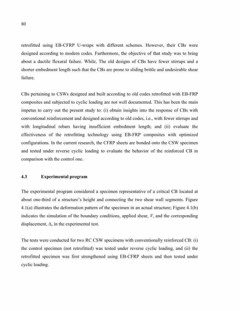
80
retrofitted using EB-CFRP U-wraps with different schemes. However, their CBs were
designed according to modern codes. Furthermore, the objective of that study was to bring
about a ductile flexural failure. While, The old designs of CBs have fewer stirrups and a
shorter embedment length such that the CBs are prone to sliding brittle and undesirable shear
failure.
CBs pertaining to CSWs designed and built according to old codes retrofitted with EB-FRP
composites and subjected to cyclic loading are not well documented. This has been the main
impetus to carry out the present study to: (i) obtain insights into the response of CBs with
conventional reinforcement and designed according to old codes, i.e., with fewer stirrups and
with longitudinal rebars having insufficient embedment length; and (ii) evaluate the
effectiveness of the retrofitting technology using EB-FRP composites with optimized
configurations. In the current research, the CFRP sheets are bonded onto the CSW specimen
and tested under reverse cyclic loading to evaluate the behavior of the reinforced CB in
comparison with the control one.
4.3 Experimental program
The experimental program considered a specimen representative of a critical CB located at
about one-third of a structure’s height and connecting the two shear wall segments. Figure
4.1(a) illustrates the deformation pattern of the specimen in an actual structure; Figure 4.1(b)
indicates the simulation of the boundary conditions, applied shear, V, and the corresponding
displacement, Δ, in the experimental test.
The tests were conducted for two RC CSW specimens with conventionally reinforced CB: (i)
the control specimen (not retrofitted) was tested under reverse cyclic loading, and (ii) the
retrofitted specimen was first strengthened using EB-CFRP sheets and then tested under
cyclic loading.
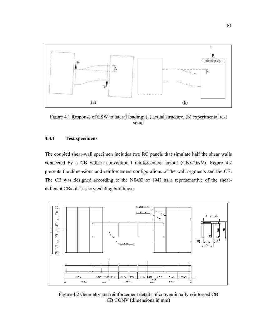
81
Figure 4.1 Response of CSW to lateral loading: (a) actual structure, (b) experimental test setup
4.3.1 Test specimens
The coupled shear-wall specimen includes two RC panels that simulate half the shear walls
connected by a CB with a conventional reinforcement layout (CB.CONV). Figure 4.2
presents the dimensions and reinforcement configurations of the wall segments and the CB.
The CB was designed according to the NBCC of 1941 as a representative of the shear-
deficient CBs of 15-story existing buildings.
Figure 4.2 Geometry and reinforcement details of conventionally reinforced CB CB.CONV (dimensions in mm)
(a) (b)
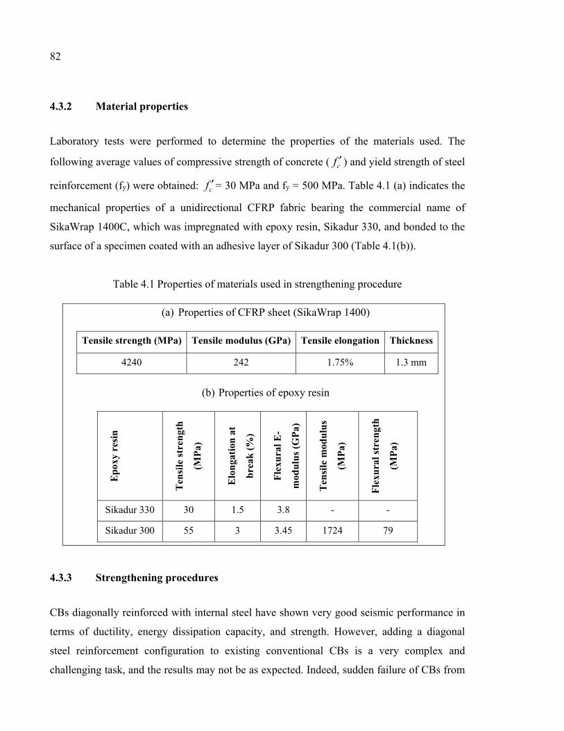
82
4.3.2 Material properties
Laboratory tests were performed to determine the properties of the materials used. The
following average values of compressive strength of concrete ( cf ′ ) and yield strength of steel
reinforcement (fy) were obtained: cf ′ = 30 MPa and fy = 500 MPa. Table 4.1 (a) indicates the
mechanical properties of a unidirectional CFRP fabric bearing the commercial name of
SikaWrap 1400C, which was impregnated with epoxy resin, Sikadur 330, and bonded to the
surface of a specimen coated with an adhesive layer of Sikadur 300 (Table 4.1(b)).
Table 4.1 Properties of materials used in strengthening procedure
(a) Properties of CFRP sheet (SikaWrap 1400)
Tensile strength (MPa) Tensile modulus (GPa) Tensile elongation Thickness
4240 242 1.75% 1.3 mm
(b) Properties of epoxy resin
Ep
oxy
resi
n
Ten
sile
str
engt
h
(MP
a)
Elo
nga
tion
at
bre
ak (
%)
Fle
xura
l E-
mod
ulu
s (G
Pa)
Ten
sile
mod
ulu
s
(MP
a)
Fle
xura
l str
engt
h
(MP
a)
Sikadur 330 30 1.5 3.8 - -
Sikadur 300 55 3 3.45 1724 79
4.3.3 Strengthening procedures
CBs diagonally reinforced with internal steel have shown very good seismic performance in
terms of ductility, energy dissipation capacity, and strength. However, adding a diagonal
steel reinforcement configuration to existing conventional CBs is a very complex and
challenging task, and the results may not be as expected. Indeed, sudden failure of CBs from
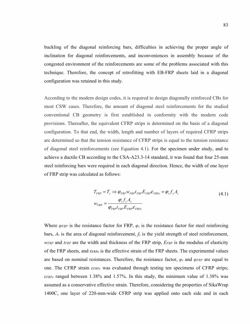
83
buckling of the diagonal reinforcing bars, difficulties in achieving the proper angle of
inclination for diagonal reinforcements, and inconveniences in assembly because of the
congested environment of the reinforcements are some of the problems associated with this
technique. Therefore, the concept of retrofitting with EB-FRP sheets laid in a diagonal
configuration was retained in this study.
According to the modern design codes, it is required to design diagonally reinforced CBs for
most CSW cases. Therefore, the amount of diagonal steel reinforcements for the studied
conventional CB geometry is first established in conformity with the modern code
provisions. Thereafter, the equivalent CFRP strips is determined on the basis of a diagonal
configuration. To that end, the width, length and number of layers of required CFRP strips
are determined so that the tension resistance of CFRP strips is equal to the tension resistance
of diagonal steel reinforcements (see Equation 4.1). For the specimen under study, and to
achieve a ductile CB according to the CSA-A23.3-14 standard, it was found that four 25-mm
steel reinforcing bars were required in each diagonal direction. Hence, the width of one layer
of FRP strip was calculated as follows:
FRPeFRPFRPFRP
sysFRP
sysFRPeFRPFRPFRPFRPsFRP
Et
Afw
AfEtwTT
εϕϕ
ϕεϕ
=
==
(4.1)
Where φFRP is the resistance factor for FRP, φs is the resistance factor for steel reinforcing
bars, As is the area of diagonal reinforcement, fy is the yield strength of steel reinforcement,
wFRP and tFRP are the width and thickness of the FRP strip, EFRP is the modulus of elasticity
of the FRP sheets, and εFRPe is the effective strain of the FRP sheets. The experimental values
are based on nominal resistances. Therefore, the resistance factor, φs and φFRP are equal to
one. The CFRP strain εFRPe was evaluated through testing ten specimens of CFRP strips;
εFRPe ranged between 1.38% and 1.57%. In this study, the minimum value of 1.38% was
assumed as a conservative effective strain. Therefore, considering the properties of SikaWrap
1400C, one layer of 220-mm-wide CFRP strip was applied onto each side and in each
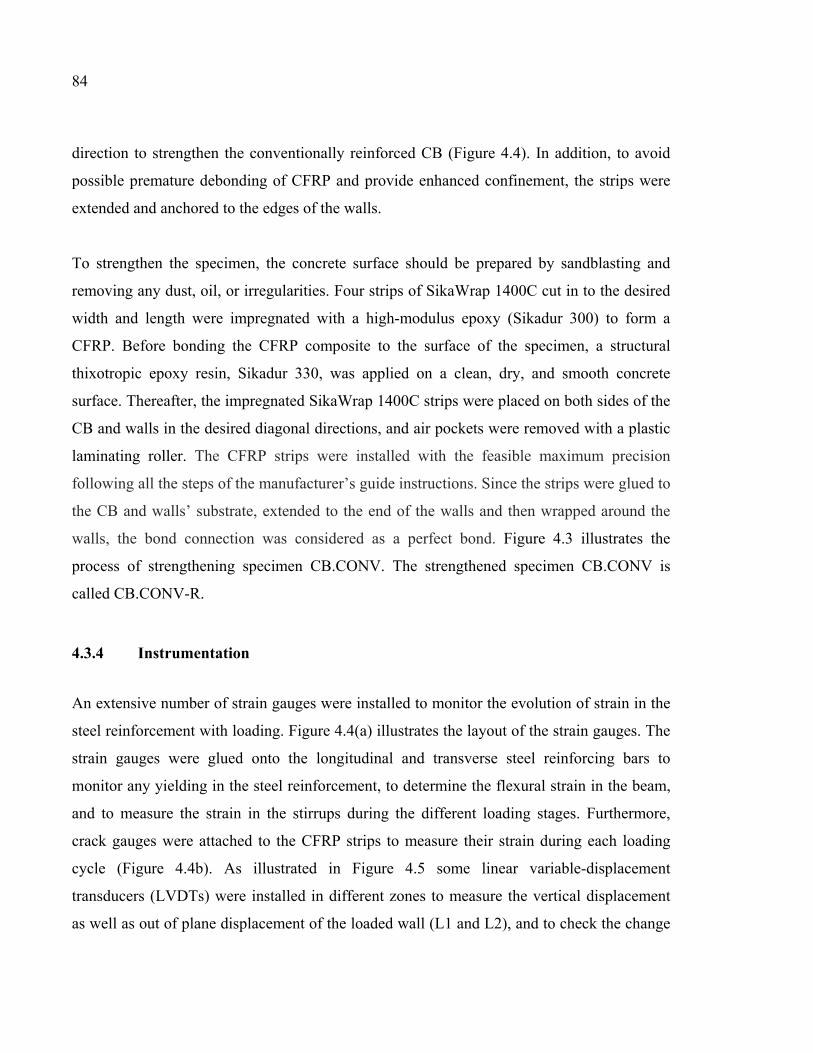
84
direction to strengthen the conventionally reinforced CB (Figure 4.4). In addition, to avoid
possible premature debonding of CFRP and provide enhanced confinement, the strips were
extended and anchored to the edges of the walls.
To strengthen the specimen, the concrete surface should be prepared by sandblasting and
removing any dust, oil, or irregularities. Four strips of SikaWrap 1400C cut in to the desired
width and length were impregnated with a high-modulus epoxy (Sikadur 300) to form a
CFRP. Before bonding the CFRP composite to the surface of the specimen, a structural
thixotropic epoxy resin, Sikadur 330, was applied on a clean, dry, and smooth concrete
surface. Thereafter, the impregnated SikaWrap 1400C strips were placed on both sides of the
CB and walls in the desired diagonal directions, and air pockets were removed with a plastic
laminating roller. The CFRP strips were installed with the feasible maximum precision
following all the steps of the manufacturer’s guide instructions. Since the strips were glued to
the CB and walls’ substrate, extended to the end of the walls and then wrapped around the
walls, the bond connection was considered as a perfect bond. Figure 4.3 illustrates the
process of strengthening specimen CB.CONV. The strengthened specimen CB.CONV is
called CB.CONV-R.
4.3.4 Instrumentation
An extensive number of strain gauges were installed to monitor the evolution of strain in the
steel reinforcement with loading. Figure 4.4(a) illustrates the layout of the strain gauges. The
strain gauges were glued onto the longitudinal and transverse steel reinforcing bars to
monitor any yielding in the steel reinforcement, to determine the flexural strain in the beam,
and to measure the strain in the stirrups during the different loading stages. Furthermore,
crack gauges were attached to the CFRP strips to measure their strain during each loading
cycle (Figure 4.4b). As illustrated in Figure 4.5 some linear variable-displacement
transducers (LVDTs) were installed in different zones to measure the vertical displacement
as well as out of plane displacement of the loaded wall (L1 and L2), and to check the change
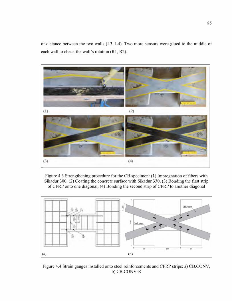
85
of distance between the two walls (L3, L4). Two more sensors were glued to the middle of
each wall to check the wall’s rotation (R1, R2).
Figure 4.3 Strengthening procedure for the CB specimen: (1) Impregnation of fibers with Sikadur 300, (2) Coating the concrete surface with Sikadur 330, (3) Bonding the first strip
of CFRP onto one diagonal, (4) Bonding the second strip of CFRP to another diagonal
Figure 4.4 Strain gauges installed onto steel reinforcements and CFRP strips: a) CB.CONV, b) CB.CONV-R
(a) (b)
86
4.3.5 Test setup and loading program
Figure 4.5 illustrates the experimental setup as well as the loading and boundary conditions
of the CSW specimens. The left wall segment was fixed to the reaction floor of the
laboratory, and the load was applied vertically to the right wall through the loading beam on
top, such that the centroids of the walls remained parallel. Upward and downward loading
was applied by two 500-kN hydraulic rams, one on each side of the CB, with their line of
action along the midspan symmetrical axis of the CB. In order to model the actual coupled
wall system, a single hydraulic ram was installed next to the loaded wall to keep the walls
parallel as well as providing forces to balance the dead load. The walls were restrained from
out-of-plane displacements.
Figure 4.5 Experimental setup
The specimens were tested under reverse cyclic loading under displacement-control
conditions, as presented in Figure 4.6. Two load cycles were applied at a rate of 3 mm/min at
each displacement amplitude, which was set equal to 0.5, 1, 2, 3, and other values, times the
value of the estimated yield displacement, ∆y, up to failure. An experimental static test was
conducted and the yield displacement was determined through the load-displacement curve
based on equivalent elastoplastic yield method with the same elastic stiffness and ultimate
load as the real system (Park, 1988). A yield displacement of 10.1 mm was obtained using
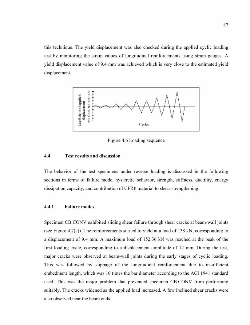
87
this technique. The yield displacement was also checked during the applied cyclic loading
test by monitoring the strain values of longitudinal reinforcements using strain gauges. A
yield displacement value of 9.4 mm was achieved which is very close to the estimated yield
displacement.
Figure 4.6 Loading sequence
4.4 Test results and discussion
The behavior of the test specimens under reverse loading is discussed in the following
sections in terms of failure mode, hysteretic behavior, strength, stiffness, ductility, energy
dissipation capacity, and contribution of CFRP material to shear strengthening.
4.4.1 Failure modes
Specimen CB.CONV exhibited sliding shear failure through shear cracks at beam-wall joints
(see Figure 4.7(a)). The reinforcements started to yield at a load of 138 kN, corresponding to
a displacement of 9.4 mm. A maximum load of 152.36 kN was reached at the peak of the
first loading cycle, corresponding to a displacement amplitude of 12 mm. During the test,
major cracks were observed at beam-wall joints during the early stages of cyclic loading.
This was followed by slippage of the longitudinal reinforcement due to insufficient
embedment length, which was 10 times the bar diameter according to the ACI 1941 standard
used. This was the major problem that prevented specimen CB.CONV from performing
suitably. The cracks widened as the applied load increased. A few inclined shear cracks were
also observed near the beam ends.
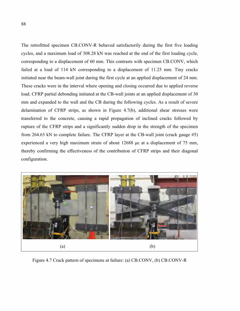
88
The retrofitted specimen CB.CONV-R behaved satisfactorily during the first five loading
cycles, and a maximum load of 308.28 kN was reached at the end of the first loading cycle,
corresponding to a displacement of 60 mm. This contrasts with specimen CB.CONV, which
failed at a load of 114 kN corresponding to a displacement of 11.25 mm. Tiny cracks
initiated near the beam-wall joint during the first cycle at an applied displacement of 24 mm.
These cracks were in the interval where opening and closing occurred due to applied reverse
load. CFRP partial debonding initiated at the CB-wall joints at an applied displacement of 30
mm and expanded to the wall and the CB during the following cycles. As a result of severe
delamination of CFRP strips, as shown in Figure 4.7(b), additional shear stresses were
transferred to the concrete, causing a rapid propagation of inclined cracks followed by
rupture of the CFRP strips and a significantly sudden drop in the strength of the specimen
from 264.63 kN to complete failure. The CFRP layer at the CB-wall joint (crack gauge #5)
experienced a very high maximum strain of about 12688 με at a displacement of 75 mm,
thereby confirming the effectiveness of the contribution of CFRP strips and their diagonal
configuration.
Figure 4.7 Crack pattern of specimens at failure: (a) CB.CONV, (b) CB.CONV-R
(a) (b)
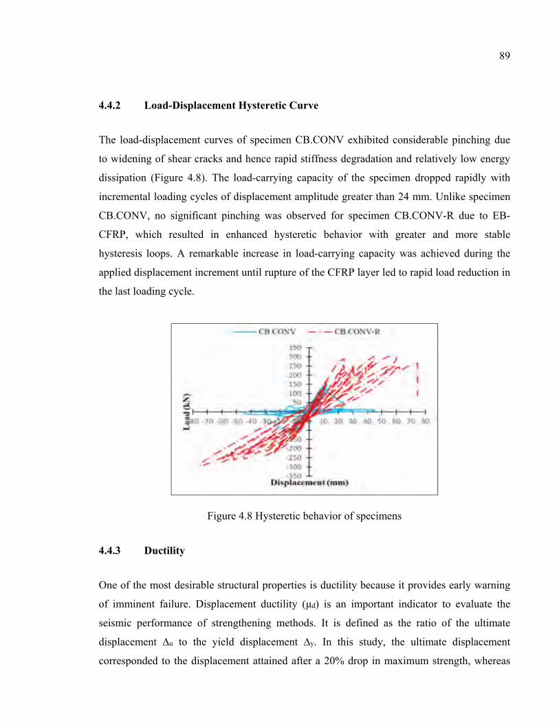
89
4.4.2 Load-Displacement Hysteretic Curve
The load-displacement curves of specimen CB.CONV exhibited considerable pinching due
to widening of shear cracks and hence rapid stiffness degradation and relatively low energy
dissipation (Figure 4.8). The load-carrying capacity of the specimen dropped rapidly with
incremental loading cycles of displacement amplitude greater than 24 mm. Unlike specimen
CB.CONV, no significant pinching was observed for specimen CB.CONV-R due to EB-
CFRP, which resulted in enhanced hysteretic behavior with greater and more stable
hysteresis loops. A remarkable increase in load-carrying capacity was achieved during the
applied displacement increment until rupture of the CFRP layer led to rapid load reduction in
the last loading cycle.
Figure 4.8 Hysteretic behavior of specimens
4.4.3 Ductility
One of the most desirable structural properties is ductility because it provides early warning
of imminent failure. Displacement ductility (μd) is an important indicator to evaluate the
seismic performance of strengthening methods. It is defined as the ratio of the ultimate
displacement ∆u to the yield displacement ∆y. In this study, the ultimate displacement
corresponded to the displacement attained after a 20% drop in maximum strength, whereas
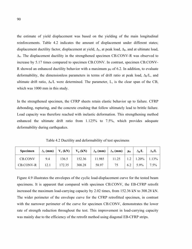
90
the estimate of yield displacement was based on the yielding of the main longitudinal
reinforcements. Table 4.2 indicates the amount of displacement under different states;
displacement ductility factor, displacement at yield, ∆y, at peak load, ∆p, and at ultimate load,
∆u. The displacement ductility in the strengthened specimen CB.CONV-R was observed to
increase by 5.17 times compared to specimen CB.CONV. In contrast, specimen CB.CONV-
R showed an enhanced ductility behavior with a maximum µd of 6.2. In addition, to evaluate
deformability, the dimensionless parameters in terms of drift ratio at peak load, ∆p/L, and
ultimate drift ratio, ∆u/L were determined. The parameter, L, is the clear span of the CB,
which was 1000 mm in this study.
In the strengthened specimen, the CFRP sheets retain elastic behavior up to failure. CFRP
debonding, rupturing, and the concrete crushing that follow ultimately lead to brittle failure.
Load capacity was therefore reached with inelastic deformation. This strengthening method
enhanced the ultimate drift ratio from 1.125% to 7.5%, which provides adequate
deformability during earthquakes.
Table 4.2 Ductility and deformability of test specimens
Specimen ∆y (mm) Vy (kN) Vp (kN) ∆p (mm) ∆u (mm) μd ∆p/L ∆u/L
CB.CONV 9.4 136.5 152.36 11.985 11.25 1.2 1.20% 1.13%
CB.CONV-R 12.1 172.35 308.28 58.97 75 6.2 5.9% 7.5%
Figure 4.9 illustrates the envelopes of the cyclic load-displacement curve for the tested beam
specimens. It is apparent that compared with specimen CB.CONV, the EB-CFRP retrofit
increased the maximum load-carrying capacity by 2.02 times, from 152.36 kN to 308.28 kN.
The wider perimeter of the envelope curve for the CFRP retrofitted specimen, in contrast
with the narrower perimeter of the curve for specimen CB.CONV, demonstrates the lower
rate of strength reduction throughout the test. This improvement in load-carrying capacity
was mainly due to the efficiency of the retrofit method using diagonal EB-CFRP strips.
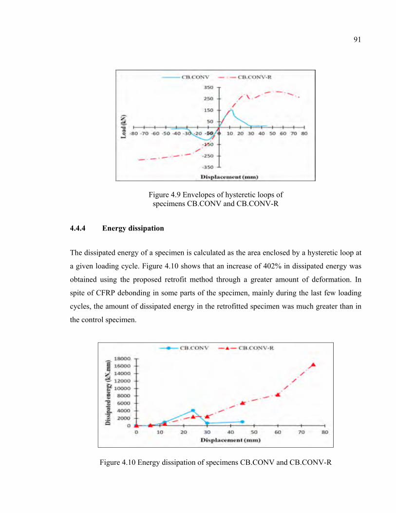
91
Figure 4.9 Envelopes of hysteretic loops of specimens CB.CONV and CB.CONV-R
4.4.4 Energy dissipation
The dissipated energy of a specimen is calculated as the area enclosed by a hysteretic loop at
a given loading cycle. Figure 4.10 shows that an increase of 402% in dissipated energy was
obtained using the proposed retrofit method through a greater amount of deformation. In
spite of CFRP debonding in some parts of the specimen, mainly during the last few loading
cycles, the amount of dissipated energy in the retrofitted specimen was much greater than in
the control specimen.
Figure 4.10 Energy dissipation of specimens CB.CONV and CB.CONV-R
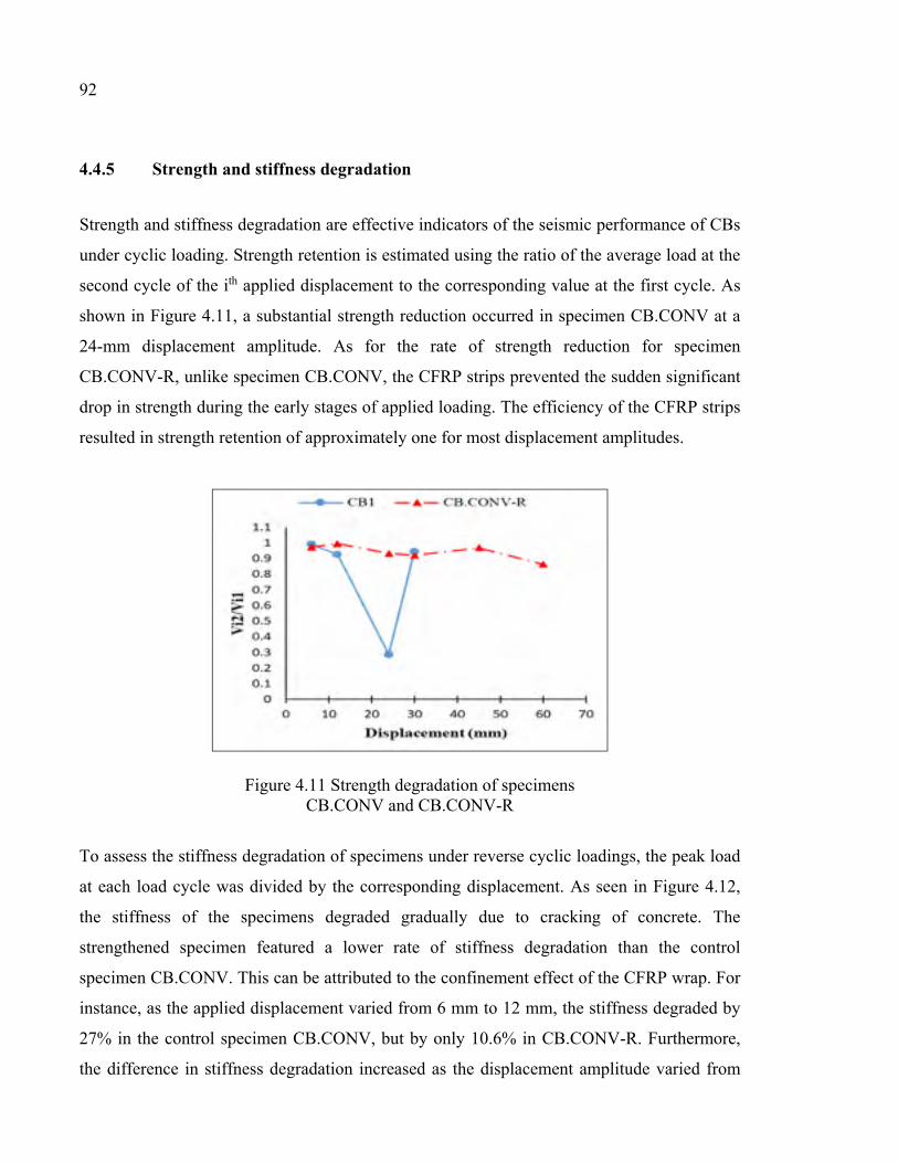
92
4.4.5 Strength and stiffness degradation
Strength and stiffness degradation are effective indicators of the seismic performance of CBs
under cyclic loading. Strength retention is estimated using the ratio of the average load at the
second cycle of the ith applied displacement to the corresponding value at the first cycle. As
shown in Figure 4.11, a substantial strength reduction occurred in specimen CB.CONV at a
24-mm displacement amplitude. As for the rate of strength reduction for specimen
CB.CONV-R, unlike specimen CB.CONV, the CFRP strips prevented the sudden significant
drop in strength during the early stages of applied loading. The efficiency of the CFRP strips
resulted in strength retention of approximately one for most displacement amplitudes.
Figure 4.11 Strength degradation of specimens CB.CONV and CB.CONV-R
To assess the stiffness degradation of specimens under reverse cyclic loadings, the peak load
at each load cycle was divided by the corresponding displacement. As seen in Figure 4.12,
the stiffness of the specimens degraded gradually due to cracking of concrete. The
strengthened specimen featured a lower rate of stiffness degradation than the control
specimen CB.CONV. This can be attributed to the confinement effect of the CFRP wrap. For
instance, as the applied displacement varied from 6 mm to 12 mm, the stiffness degraded by
27% in the control specimen CB.CONV, but by only 10.6% in CB.CONV-R. Furthermore,
the difference in stiffness degradation increased as the displacement amplitude varied from
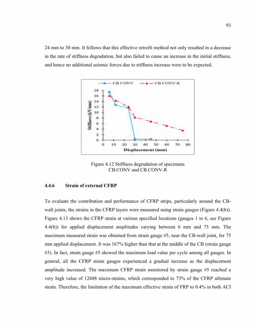
93
24 mm to 30 mm. It follows that this effective retrofit method not only resulted in a decrease
in the rate of stiffness degradation, but also failed to cause an increase in the initial stiffness,
and hence no additional seismic forces due to stiffness increase were to be expected.
Figure 4.12 Stiffness degradation of specimens CB.CONV and CB.CONV-R
4.4.6 Strain of external CFRP
To evaluate the contribution and performance of CFRP strips, particularly around the CB-
wall joints, the strains in the CFRP layers were measured using strain gauges (Figure 4.4(b)).
Figure 4.13 shows the CFRP strain at various specified locations (gauges 1 to 6, see Figure
4.4(b)) for applied displacement amplitudes varying between 6 mm and 75 mm. The
maximum measured strain was obtained from strain gauge #5, near the CB-wall joint, for 75
mm applied displacement. It was 167% higher than that at the middle of the CB (strain gauge
#3). In fact, strain gauge #5 showed the maximum load value per cycle among all gauges. In
general, all the CFRP strain gauges experienced a gradual increase as the displacement
amplitude increased. The maximum CFRP strain monitored by strain gauge #5 reached a
very high value of 12688 micro-strains, which corresponded to 73% of the CFRP ultimate
strain. Therefore, the limitation of the maximum effective strain of FRP to 0.4% in both ACI
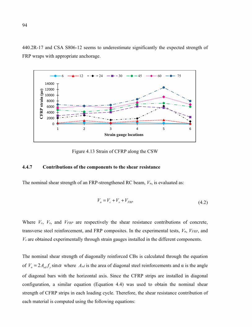
94
440.2R-17 and CSA S806-12 seems to underestimate significantly the expected strength of
FRP wraps with appropriate anchorage.
Figure 4.13 Strain of CFRP along the CSW
4.4.7 Contributions of the components to the shear resistance
The nominal shear strength of an FRP-strengthened RC beam, Vn, is evaluated as:
FRPscn VVVV ++= (4.2)
Where Vc, Vs, and VFRP are respectively the shear resistance contributions of concrete,
transverse steel reinforcement, and FRP composites. In the experimental tests, Vn, VFRP, and
Vs are obtained experimentally through strain gauges installed in the different components.
The nominal shear strength of diagonally reinforced CBs is calculated through the equation
of αsin2 ysdn fAV = where Asd is the area of diagonal steel reinforcements and α is the angle
of diagonal bars with the horizontal axis. Since the CFRP strips are installed in diagonal
configuration, a similar equation (Equation 4.4) was used to obtain the nominal shear
strength of CFRP strips in each loading cycle. Therefore, the shear resistance contribution of
each material is computed using the following equations:
02000400060008000
100001200014000
1 2 3 4 5 6
CF
RP
str
ain
(µ
e)
Strain gauge locations
6 12 24 30 45 60 75
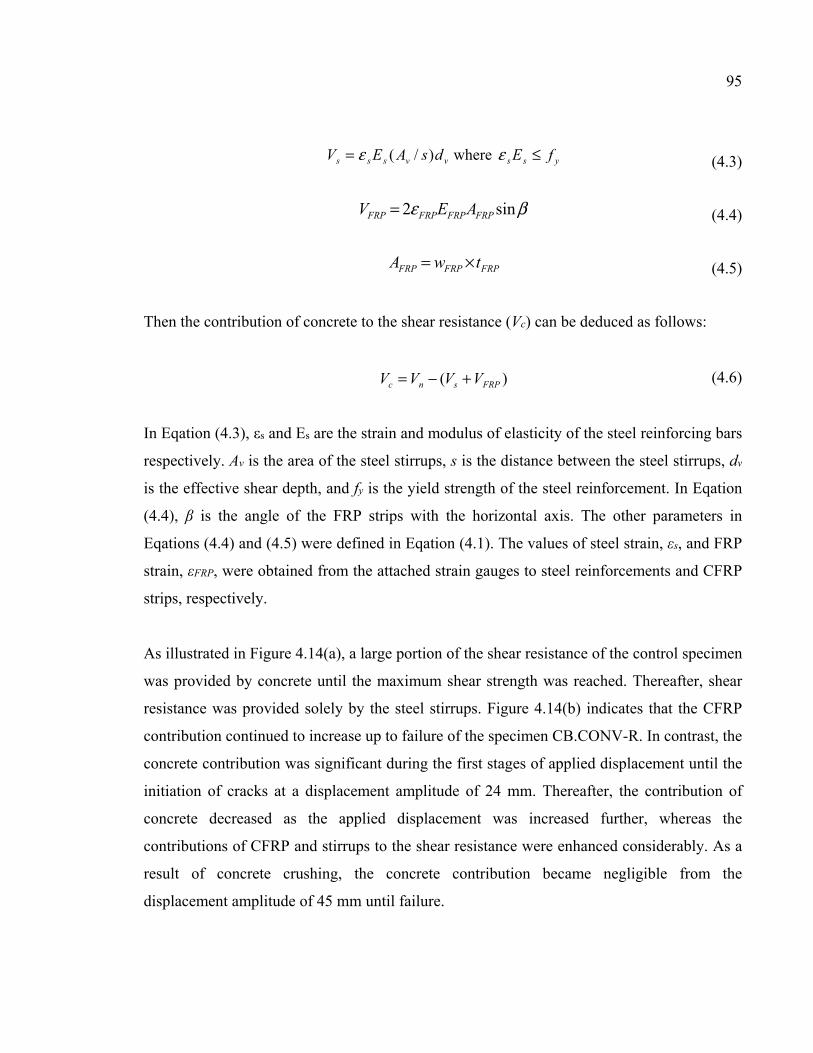
95
yssvvsss fEdsAEV ≤= εε where)/( (4.3)
βε sin2 FRPFRPFRPFRP AEV = (4.4)
FRPFRPFRP twA ×= (4.5)
Then the contribution of concrete to the shear resistance (Vc) can be deduced as follows:
)( FRPsnc VVVV +−= (4.6)
In Eqation (4.3), εs and Es are the strain and modulus of elasticity of the steel reinforcing bars
respectively. Av is the area of the steel stirrups, s is the distance between the steel stirrups, dv
is the effective shear depth, and fy is the yield strength of the steel reinforcement. In Eqation
(4.4), β is the angle of the FRP strips with the horizontal axis. The other parameters in
Eqations (4.4) and (4.5) were defined in Eqation (4.1). The values of steel strain, εs, and FRP
strain, εFRP, were obtained from the attached strain gauges to steel reinforcements and CFRP
strips, respectively.
As illustrated in Figure 4.14(a), a large portion of the shear resistance of the control specimen
was provided by concrete until the maximum shear strength was reached. Thereafter, shear
resistance was provided solely by the steel stirrups. Figure 4.14(b) indicates that the CFRP
contribution continued to increase up to failure of the specimen CB.CONV-R. In contrast, the
concrete contribution was significant during the first stages of applied displacement until the
initiation of cracks at a displacement amplitude of 24 mm. Thereafter, the contribution of
concrete decreased as the applied displacement was increased further, whereas the
contributions of CFRP and stirrups to the shear resistance were enhanced considerably. As a
result of concrete crushing, the concrete contribution became negligible from the
displacement amplitude of 45 mm until failure.
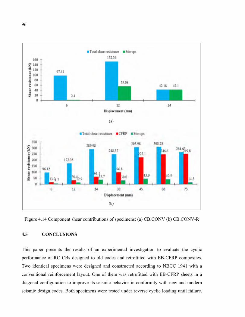
96
Figure 4.14 Component shear contributions of specimens: (a) CB.CONV (b) CB.CONV-R
4.5 CONCLUSIONS
This paper presents the results of an experimental investigation to evaluate the cyclic
performance of RC CBs designed to old codes and retrofitted with EB-CFRP composites.
Two identical specimens were designed and constructed according to NBCC 1941 with a
conventional reinforcement layout. One of them was retrofitted with EB-CFRP sheets in a
diagonal configuration to improve its seismic behavior in conformity with new and modern
seismic design codes. Both specimens were tested under reverse cyclic loading until failure.
(a)
(b)
97
Although all the data were collected carefully with maximum accuracy, it is fair to add that
the findings are to be used with caution since the number of specimens is limited. The
following conclusions can be drawn:
a) Use of CFRP sheets in a diagonal configuration to retrofit the CBs of CSWs has proven
to be a promising retrofitting technique; it resulted in a substantial increase in the load-
resisting capacity, deformability, strength, ductility, and energy dissipation capacity of
the specimen.
b) Diagonal EB-CFRP was found to be effective in preventing sliding shear failure, which
was observed in the unstrengthened control specimen CB.CONV.
c) Diagonal EB-CFRP converted the weak hysteresis behavior characterized by significant
pinching observed in the CB of the control specimen to more stable hysteretic curves.
d) The ductility of the control specimen was 1.2, which is very low. Use of diagonal EB-
CFRP sheets resulted in a substantially enhanced ductility of 6.2.
e) The conventionally reinforced CB exhibited considerable strength and stiffness
degradation. This contrasts with the strengthened specimen, which offered greater
strength retention due to more stable cyclic behavior.
f) The EB-CFRP wrap was actively engaged in resisting shear, particularly after the
initiation of concrete cracking up to failure. This was observed by noting the significant
strain capacity of the CFRP composites.
g) The weak performance of the conventionally reinforced CB indicates that the retrofit of
existing CSWs designed to old codes and located in seismic regions is inevitable. The
retrofit method developed in this study using diagonally configured EB-CFRP is a
practical and effective method to overcome the deficiencies and drawbacks of
conventional seismic strengthening approaches.

CHAPTER 5
SEISMIC RETROFIT OF PRE-DAMAGED DIAGONALLY RC CBS USING EXTERNALLY BONDED CFRP COMPOSITES
Sara Honarparast a, Omar Chaallal b, F.ASCE and Georges El-Saikaly c
a, b, c Department of Construction Engineering, École de Technologie Supérieure,
1100 Notre-Dame West, Montreal, Quebec, Canada H3C 1K3
Paper submitted in Journal of Composite Structures, October, 2018.
5.1 Abstract
This study aims to investigate a new repair method using EB-CFRP composites for existing
pre-damaged RC CBs pertaining to a RC CSW that underwent a seismic event. To this end,
an experimental test was conducted on a specimen designed and constructed according to the
modern and recent Canadian code and Standards with a diagonally reinforced CB. It was
tested under reversed cyclic loading until failure. The damaged specimen was then repaired
using EB-CFRP composites and retested to evaluate its seismic performance. The
experimental results revealed that the retrofit method using diagonal configuration of CFRP
strips is an effective technique in restoring the seismic performance of the initial specimen. It
also provided enhancements with regard to the hysteretic and ductile behavior, energy
dissipation capacity, and stiffness degradation.
5.2 Introduction
Reinforced concrete CSWs with adequate strength and stiffness have proven to be an
effective system for resisting lateral forces in medium to high rise buildings. In this system,
the lateral forces are resisted through the shear and moment resistance of the wall segments
as well as the action of the CBs. In CSWs, the shear forces are transferred through the CBs,
and the overturning moment is partially resisted by an axial compression-tension that is
coupled across the walls. In well-designed CSWs, CBs are the primary energy-dissipation
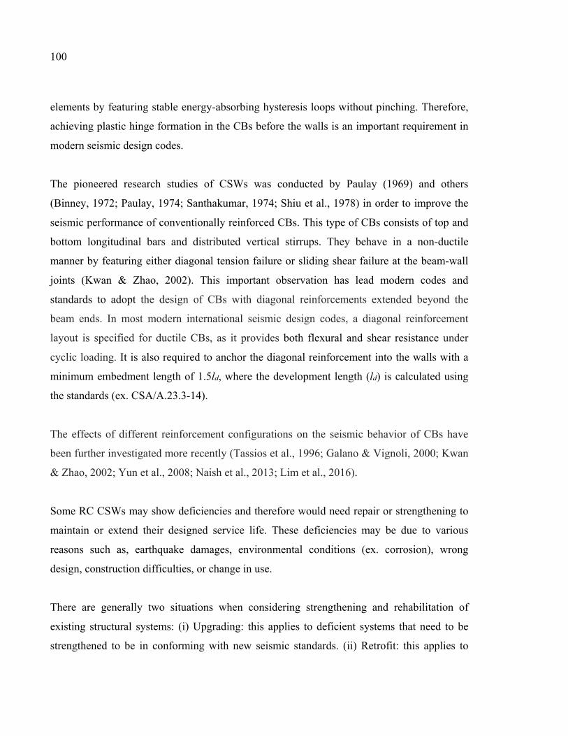
100
elements by featuring stable energy-absorbing hysteresis loops without pinching. Therefore,
achieving plastic hinge formation in the CBs before the walls is an important requirement in
modern seismic design codes.
The pioneered research studies of CSWs was conducted by Paulay (1969) and others
(Binney, 1972; Paulay, 1974; Santhakumar, 1974; Shiu et al., 1978) in order to improve the
seismic performance of conventionally reinforced CBs. This type of CBs consists of top and
bottom longitudinal bars and distributed vertical stirrups. They behave in a non-ductile
manner by featuring either diagonal tension failure or sliding shear failure at the beam-wall
joints (Kwan & Zhao, 2002). This important observation has lead modern codes and
standards to adopt the design of CBs with diagonal reinforcements extended beyond the
beam ends. In most modern international seismic design codes, a diagonal reinforcement
layout is specified for ductile CBs, as it provides both flexural and shear resistance under
cyclic loading. It is also required to anchor the diagonal reinforcement into the walls with a
minimum embedment length of 1.5ld, where the development length (ld) is calculated using
the standards (ex. CSA/A.23.3-14).
The effects of different reinforcement configurations on the seismic behavior of CBs have
been further investigated more recently (Tassios et al., 1996; Galano & Vignoli, 2000; Kwan
& Zhao, 2002; Yun et al., 2008; Naish et al., 2013; Lim et al., 2016).
Some RC CSWs may show deficiencies and therefore would need repair or strengthening to
maintain or extend their designed service life. These deficiencies may be due to various
reasons such as, earthquake damages, environmental conditions (ex. corrosion), wrong
design, construction difficulties, or change in use.
There are generally two situations when considering strengthening and rehabilitation of
existing structural systems: (i) Upgrading: this applies to deficient systems that need to be
strengthened to be in conforming with new seismic standards. (ii) Retrofit: this applies to
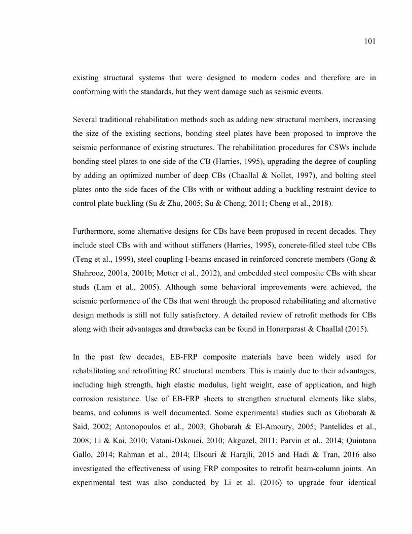
101
existing structural systems that were designed to modern codes and therefore are in
conforming with the standards, but they went damage such as seismic events.
Several traditional rehabilitation methods such as adding new structural members, increasing
the size of the existing sections, bonding steel plates have been proposed to improve the
seismic performance of existing structures. The rehabilitation procedures for CSWs include
bonding steel plates to one side of the CB (Harries, 1995), upgrading the degree of coupling
by adding an optimized number of deep CBs (Chaallal & Nollet, 1997), and bolting steel
plates onto the side faces of the CBs with or without adding a buckling restraint device to
control plate buckling (Su & Zhu, 2005; Su & Cheng, 2011; Cheng et al., 2018).
Furthermore, some alternative designs for CBs have been proposed in recent decades. They
include steel CBs with and without stiffeners (Harries, 1995), concrete-filled steel tube CBs
(Teng et al., 1999), steel coupling I-beams encased in reinforced concrete members (Gong &
Shahrooz, 2001a, 2001b; Motter et al., 2012), and embedded steel composite CBs with shear
studs (Lam et al., 2005). Although some behavioral improvements were achieved, the
seismic performance of the CBs that went through the proposed rehabilitating and alternative
design methods is still not fully satisfactory. A detailed review of retrofit methods for CBs
along with their advantages and drawbacks can be found in Honarparast & Chaallal (2015).
In the past few decades, EB-FRP composite materials have been widely used for
rehabilitating and retrofitting RC structural members. This is mainly due to their advantages,
including high strength, high elastic modulus, light weight, ease of application, and high
corrosion resistance. Use of EB-FRP sheets to strengthen structural elements like slabs,
beams, and columns is well documented. Some experimental studies such as Ghobarah &
Said, 2002; Antonopoulos et al., 2003; Ghobarah & El-Amoury, 2005; Pantelides et al.,
2008; Li & Kai, 2010; Vatani-Oskouei, 2010; Akguzel, 2011; Parvin et al., 2014; Quintana
Gallo, 2014; Rahman et al., 2014; Elsouri & Harajli, 2015 and Hadi & Tran, 2016 also
investigated the effectiveness of using FRP composites to retrofit beam-column joints. An
experimental test was also conducted by Li et al. (2016) to upgrade four identical
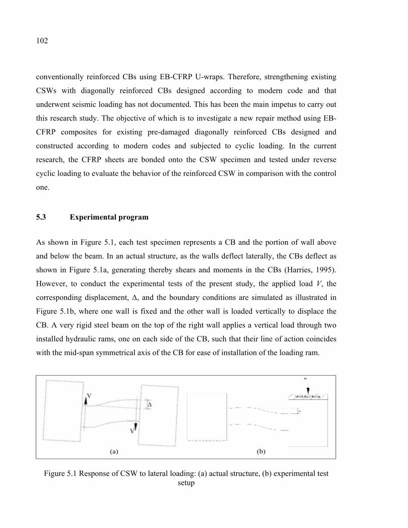
102
conventionally reinforced CBs using EB-CFRP U-wraps. Therefore, strengthening existing
CSWs with diagonally reinforced CBs designed according to modern code and that
underwent seismic loading has not documented. This has been the main impetus to carry out
this research study. The objective of which is to investigate a new repair method using EB-
CFRP composites for existing pre-damaged diagonally reinforced CBs designed and
constructed according to modern codes and subjected to cyclic loading. In the current
research, the CFRP sheets are bonded onto the CSW specimen and tested under reverse
cyclic loading to evaluate the behavior of the reinforced CSW in comparison with the control
one.
5.3 Experimental program
As shown in Figure 5.1, each test specimen represents a CB and the portion of wall above
and below the beam. In an actual structure, as the walls deflect laterally, the CBs deflect as
shown in Figure 5.1a, generating thereby shears and moments in the CBs (Harries, 1995).
However, to conduct the experimental tests of the present study, the applied load V, the
corresponding displacement, Δ, and the boundary conditions are simulated as illustrated in
Figure 5.1b, where one wall is fixed and the other wall is loaded vertically to displace the
CB. A very rigid steel beam on the top of the right wall applies a vertical load through two
installed hydraulic rams, one on each side of the CB, such that their line of action coincides
with the mid-span symmetrical axis of the CB for ease of installation of the loading ram.
Figure 5.1 Response of CSW to lateral loading: (a) actual structure, (b) experimental test setup
(a) (b)
103
5.3.1 Test specimen and instrumentation
The tests were conducted on a RC coupled shear-wall specimen with diagonally reinforced
CB. The specimen consisted of two RC panels that simulated half of the shear walls,
connected by a CB with a cross section of 500 mm (depth) × 250 mm (width) and a clear
span of 1000 mm. It was designed according to the requirements of modern Canadian
standard CSA A23.3-14. The CB was reinforced with four 25 mm-diameter reinforcement
bars in each diagonal direction with ten 10 mm-diameter closed stirrups spaced at 100 mm
(Figure 5.2a). The experimental tests were performed in two phases as follows: (i) the
modern-designed control specimen was tested under reverse cyclic loading until failure, and
(ii) the damaged specimen was repaired and retrofitted using EB-CFRP sheets and retested
under cyclic loading.
A comprehensive number of strain gauges were installed to monitor strain variations in the
steel reinforcements with load. The layout of the strain gauges is illustrated in Figure 5.2a.
The strain gauges were glued onto the longitudinal and diagonal steel reinforcing bars
especially close to critical location of CB-wall joints. The gauges were attached at the front
and back sides, at the top and bottom of the CBs to monitor the strain magnitude in different
locations as well as steel yielding with applied loading. A few strain gauges were also
attached to the stirrups to monitor their behavior with loading. Additionally, as illustrated in
Figure 5.4 (test setup) some LVDTs were installed in different zones to measure the vertical
displacement as well as the out of plane displacement of the loaded wall (L1 and L2), and to
check the change of the distance between the two walls (L3, L4). Two more sensors were
glued to the middle of each wall to check the wall’s rotation (R1, R2). After retrofitting of
the damaged specimen, crack gauges were externally attached on the CFRP strips to monitor
the strain experienced by the EB-CFRP during each loading cycle (Figure 5.2b).
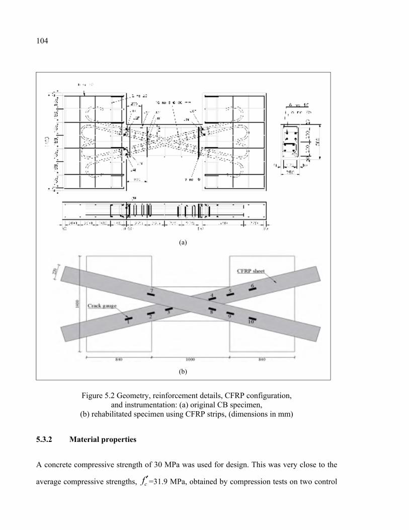
104
Figure 5.2 Geometry, reinforcement details, CFRP configuration, and instrumentation: (a) original CB specimen,
(b) rehabilitated specimen using CFRP strips, (dimensions in mm)
5.3.2 Material properties
A concrete compressive strength of 30 MPa was used for design. This was very close to the
average compressive strengths, cf ′=31.9 MPa, obtained by compression tests on two control
(a)
(b)
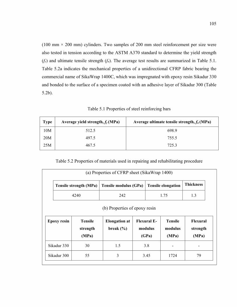
105
(100 mm × 200 mm) cylinders. Two samples of 200 mm steel reinforcement per size were
also tested in tension according to the ASTM A370 standard to determine the yield strength
(fy) and ultimate tensile strength (fu). The average test results are summarized in Table 5.1.
Table 5.2a indicates the mechanical properties of a unidirectional CFRP fabric bearing the
commercial name of SikaWrap 1400C, which was impregnated with epoxy resin Sikadur 330
and bonded to the surface of a specimen coated with an adhesive layer of Sikadur 300 (Table
5.2b).
Table 5.1 Properties of steel reinforcing bars
Type Average yield strength, fy (MPa) Average ultimate tensile strength, fu (MPa)
10M
20M
25M
512.5
497.5
467.5
698.9
755.5
725.3
Table 5.2 Properties of materials used in repairing and rehabilitating procedure
(a) Properties of CFRP sheet (SikaWrap 1400)
Tensile strength (MPa) Tensile modulus (GPa) Tensile elongation Thickness
4240 242 1.75 1.3
(b) Properties of epoxy resin
Epoxy resin Tensile
strength
(MPa)
Elongation at
break (%)
Flexural E-
modulus
(GPa)
Tensile
modulus
(MPa)
Flexural
strength
(MPa)
Sikadur 330 30 1.5 3.8 - -
Sikadur 300 55 3 3.45 1724 79
106
5.3.3 Repairing procedures
It is required to repair the damaged specimen, CB.DIAG, before retrofitting the CBs with
CFRP sheets. To this end, the deteriorated and delaminated concrete was first located and
identified. Then, the concrete was removed around the reinforcing steels to provide adequate
clearance. The bond-inhibiting materials such as dirt, concrete slurry, and loosely bonded
concrete were removed by high-pressure water blasting to obtain a clean exposed aggregate
surface profile. Steel reinforcement was also cleaned by removing all traces of rust. The
specimen was then repaired by means of a sand-free and cementitious grout, SikaGrout
300PT, and early strength gaining, cementitious repair mortar, Sika MonoTop-623.
According to the manufacture’s guideline, a thin bond coat of the repair mortar was scrubbed
into the saturated, surface dry substrate, thus pores were filled to ensure intimate contact. The
repair material was consolidated into the corners of the patch and around any exposed
reinforcement in the repair zone. Once the desired thickness was attained, the level was
stroke off with the adjacent concrete. Figure 5.3a illustrates the repair steps of the damaged
specimen.
After the concrete and steel have been repaired and cured, the seismic retrofit of the damaged
specimen using EB-CFRP was implemented. To that end, the required width and length of
the CFRP diagonal strip were determined so that the ultimate maximum tension resistance of
CFRP strips is equal to the tension resistance of the diagonal steel reinforcements. Hence, the
width of one layer of FRP strip was calculated as follows:
sysFRPeFRPFRPFRPFRPsFRP AfEtwTT ϕεϕ == (5.1)
And hence:
FRPeFRPFRPFRP
sysFRP Et
Afw
εϕϕ
= (5.2)
107
Where φFRP is the resistance factor for FRP, φs is the resistance factor for steel reinforcing
bars, As is the area of diagonal reinforcement, fy is the yield strength of steel reinforcement,
wFRP is the width of the FRP strip, EFRP is the modulus of elasticity of the FRP sheets, and
εFRPe is the effective strain of the FRP sheets. Therefore, considering the properties of
SikaWrap 1400C, one layer of 220-mm-wide CFRP strip was applied onto each side and in
each direction to rehabilitate the diagonally reinforced CB (Figure 5.2b). In addition, to avoid
possible premature debonding of CFRP and provide enhanced confinement, the strips were
extended and anchored to the edges of the walls.
To seismically retrofit the specimen, the concrete surface was prepared by sandblasting and
removing any dust, oil, or irregularities. Four strips of SikaWrap 1400C cut to the desired
width and length were impregnated with a high-modulus epoxy (Sikadur 300) to form a
CFRP. Before bonding the CFRP composite to the surface of the specimen, a structural
thixotropic epoxy resin, Sikadur 330, was applied on the clean, dry, and prepared concrete
surface. Thereafter, the impregnated SikaWrap 1400C strips were installed on both sides of
the CB and walls in the desired diagonal directions, and air pockets were removed with a
plastic laminating roller. Figure 5.3 illustrates the retrofit process of specimen CB.DIAG.
The CFRP-retrofitted specimen CB.DIAG is labelled CB.DIAG-R.
5.3.4 Test setup and loading program
Figure 5.4 illustrates the experimental setup and the loading and boundary conditions of the
CSW specimens. The left wall was fixed to the reaction strong floor of the laboratory, and
the load was applied vertically to the right wall through the loading beam on top. In order to
model the actual coupled wall system, the centroid axes of walls should be maintained
parallel during the test. Therefore, a single hydraulic ram was installed next to the loaded
wall to keep the walls parallel as well as to provide the force to balance the dead load.
Upward and downward loading was applied by two 500 kN hydraulic rams, one on each side
of the CB, their line of action being the midspan symmetrical axis of the CB. The walls were
also restrained from out-of-plane displacements. The specimens were tested under reverse
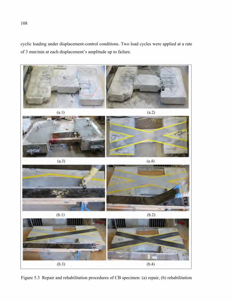
108
cyclic loading under displacement-control conditions. Two load cycles were applied at a rate
of 3 mm/min at each displacement’s amplitude up to failure.
Figure 5.3 Repair and rehabilitation procedures of CB specimen: (a) repair, (b) rehabilitation
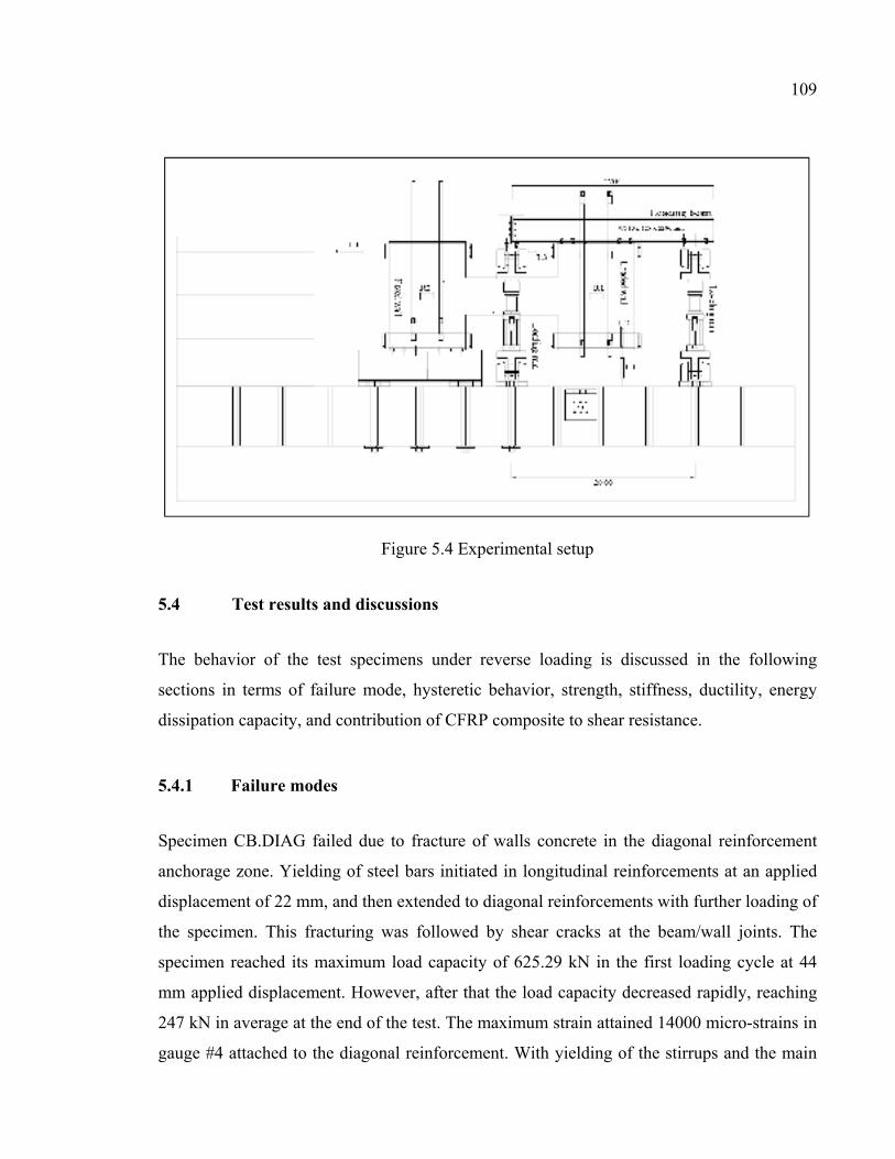
109
Figure 5.4 Experimental setup
5.4 Test results and discussions
The behavior of the test specimens under reverse loading is discussed in the following
sections in terms of failure mode, hysteretic behavior, strength, stiffness, ductility, energy
dissipation capacity, and contribution of CFRP composite to shear resistance.
5.4.1 Failure modes
Specimen CB.DIAG failed due to fracture of walls concrete in the diagonal reinforcement
anchorage zone. Yielding of steel bars initiated in longitudinal reinforcements at an applied
displacement of 22 mm, and then extended to diagonal reinforcements with further loading of
the specimen. This fracturing was followed by shear cracks at the beam/wall joints. The
specimen reached its maximum load capacity of 625.29 kN in the first loading cycle at 44
mm applied displacement. However, after that the load capacity decreased rapidly, reaching
247 kN in average at the end of the test. The maximum strain attained 14000 micro-strains in
gauge #4 attached to the diagonal reinforcement. With yielding of the stirrups and the main
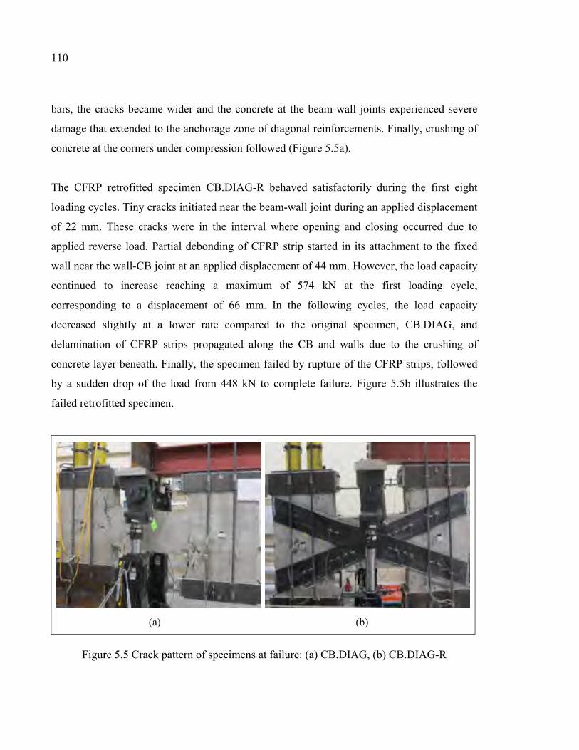
110
bars, the cracks became wider and the concrete at the beam-wall joints experienced severe
damage that extended to the anchorage zone of diagonal reinforcements. Finally, crushing of
concrete at the corners under compression followed (Figure 5.5a).
The CFRP retrofitted specimen CB.DIAG-R behaved satisfactorily during the first eight
loading cycles. Tiny cracks initiated near the beam-wall joint during an applied displacement
of 22 mm. These cracks were in the interval where opening and closing occurred due to
applied reverse load. Partial debonding of CFRP strip started in its attachment to the fixed
wall near the wall-CB joint at an applied displacement of 44 mm. However, the load capacity
continued to increase reaching a maximum of 574 kN at the first loading cycle,
corresponding to a displacement of 66 mm. In the following cycles, the load capacity
decreased slightly at a lower rate compared to the original specimen, CB.DIAG, and
delamination of CFRP strips propagated along the CB and walls due to the crushing of
concrete layer beneath. Finally, the specimen failed by rupture of the CFRP strips, followed
by a sudden drop of the load from 448 kN to complete failure. Figure 5.5b illustrates the
failed retrofitted specimen.
Figure 5.5 Crack pattern of specimens at failure: (a) CB.DIAG, (b) CB.DIAG-R
(a) (b)
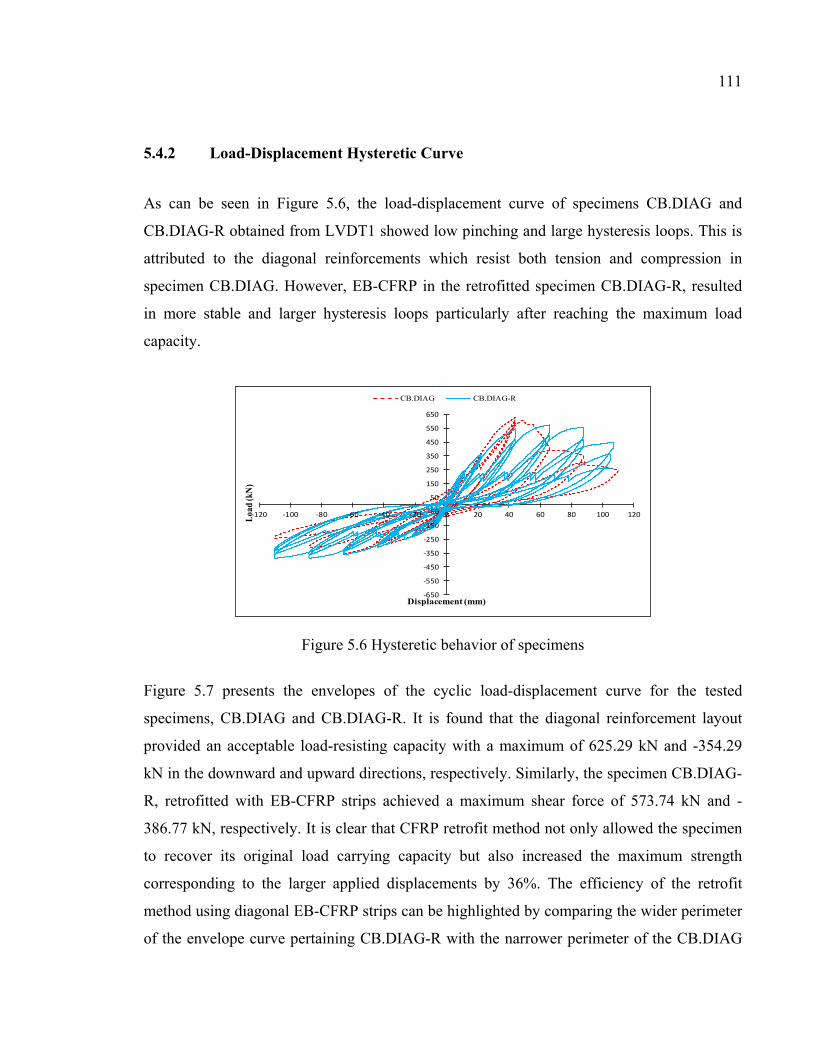
111
5.4.2 Load-Displacement Hysteretic Curve
As can be seen in Figure 5.6, the load-displacement curve of specimens CB.DIAG and
CB.DIAG-R obtained from LVDT1 showed low pinching and large hysteresis loops. This is
attributed to the diagonal reinforcements which resist both tension and compression in
specimen CB.DIAG. However, EB-CFRP in the retrofitted specimen CB.DIAG-R, resulted
in more stable and larger hysteresis loops particularly after reaching the maximum load
capacity.
Figure 5.6 Hysteretic behavior of specimens
Figure 5.7 presents the envelopes of the cyclic load-displacement curve for the tested
specimens, CB.DIAG and CB.DIAG-R. It is found that the diagonal reinforcement layout
provided an acceptable load-resisting capacity with a maximum of 625.29 kN and -354.29
kN in the downward and upward directions, respectively. Similarly, the specimen CB.DIAG-
R, retrofitted with EB-CFRP strips achieved a maximum shear force of 573.74 kN and -
386.77 kN, respectively. It is clear that CFRP retrofit method not only allowed the specimen
to recover its original load carrying capacity but also increased the maximum strength
corresponding to the larger applied displacements by 36%. The efficiency of the retrofit
method using diagonal EB-CFRP strips can be highlighted by comparing the wider perimeter
of the envelope curve pertaining CB.DIAG-R with the narrower perimeter of the CB.DIAG
-650
-550
-450
-350
-250
-150
-50
50
150
250
350
450
550
650
-120 -100 -80 -60 -40 -20 0 20 40 60 80 100 120Loa
d (k
N)
Displacement (mm)
CB.DIAG CB.DIAG-R
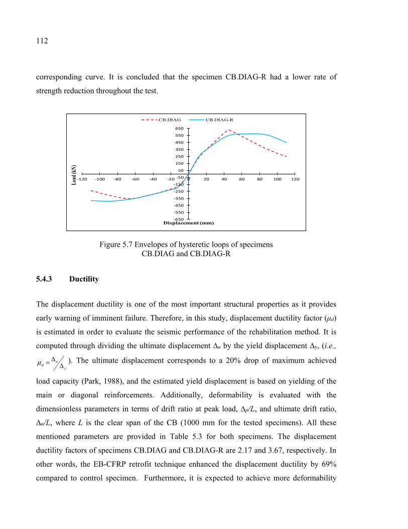
112
corresponding curve. It is concluded that the specimen CB.DIAG-R had a lower rate of
strength reduction throughout the test.
Figure 5.7 Envelopes of hysteretic loops of specimens CB.DIAG and CB.DIAG-R
5.4.3 Ductility
The displacement ductility is one of the most important structural properties as it provides
early warning of imminent failure. Therefore, in this study, displacement ductility factor (μd)
is estimated in order to evaluate the seismic performance of the rehabilitation method. It is
computed through dividing the ultimate displacement ∆u by the yield displacement ∆y, (i.e.,
y
ud Δ
Δ=μ ). The ultimate displacement corresponds to a 20% drop of maximum achieved
load capacity (Park, 1988), and the estimated yield displacement is based on yielding of the
main or diagonal reinforcements. Additionally, deformability is evaluated with the
dimensionless parameters in terms of drift ratio at peak load, ∆p/L, and ultimate drift ratio,
∆u/L, where L is the clear span of the CB (1000 mm for the tested specimens). All these
mentioned parameters are provided in Table 5.3 for both specimens. The displacement
ductility factors of specimens CB.DIAG and CB.DIAG-R are 2.17 and 3.67, respectively. In
other words, the EB-CFRP retrofit technique enhanced the displacement ductility by 69%
compared to control specimen. Furthermore, it is expected to achieve more deformability
-650
-550
-450
-350
-250
-150
-50
50
150
250
350
450
550
650
-120 -100 -80 -60 -40 -20 0 20 40 60 80 100 120
Load
(kN
)
Displacement (mm)
CB.DIAG CB.DIAG-R
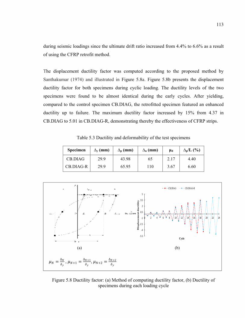
113
during seismic loadings since the ultimate drift ratio increased from 4.4% to 6.6% as a result
of using the CFRP retrofit method.
The displacement ductility factor was computed according to the proposed method by
Santhakumar (1974) and illustrated in Figure 5.8a. Figure 5.8b presents the displacement
ductility factor for both specimens during cyclic loading. The ductility levels of the two
specimens were found to be almost identical during the early cycles. After yielding,
compared to the control specimen CB.DIAG, the retrofitted specimen featured an enhanced
ductility up to failure. The maximum ductility factor increased by 15% from 4.37 in
CB.DIAG to 5.01 in CB.DIAG-R, demonstrating thereby the effectiveness of CFRP strips.
Table 5.3 Ductility and deformability of the test specimens
Specimen ∆y (mm) ∆p (mm) ∆u (mm) μd ∆p/L (%)
CB.DIAG 29.9 43.98 65 2.17 4.40
CB.DIAG-R 29.9 65.95 110 3.67 6.60
Figure 5.8 Ductility factor: (a) Method of computing ductility factor, (b) Ductility of specimens during each loading cycle
-5.5
-4
-2.5
-1
0.5
2
3.5
5
0 2 4 6 8 10 12 14 16 18 20 22 24
Dis
pla
cem
en
t d
ucti
lity
Cycle
CB.DIAG CB.DIAG-R
(a) (b)
= ∆ , +1 = ∆ +1, +2 = ∆ +2
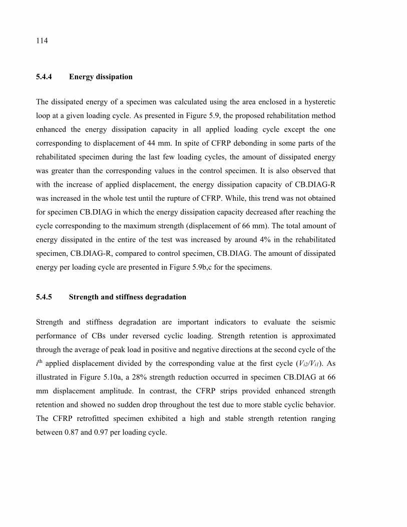
114
5.4.4 Energy dissipation
The dissipated energy of a specimen was calculated using the area enclosed in a hysteretic
loop at a given loading cycle. As presented in Figure 5.9, the proposed rehabilitation method
enhanced the energy dissipation capacity in all applied loading cycle except the one
corresponding to displacement of 44 mm. In spite of CFRP debonding in some parts of the
rehabilitated specimen during the last few loading cycles, the amount of dissipated energy
was greater than the corresponding values in the control specimen. It is also observed that
with the increase of applied displacement, the energy dissipation capacity of CB.DIAG-R
was increased in the whole test until the rupture of CFRP. While, this trend was not obtained
for specimen CB.DIAG in which the energy dissipation capacity decreased after reaching the
cycle corresponding to the maximum strength (displacement of 66 mm). The total amount of
energy dissipated in the entire of the test was increased by around 4% in the rehabilitated
specimen, CB.DIAG-R, compared to control specimen, CB.DIAG. The amount of dissipated
energy per loading cycle are presented in Figure 5.9b,c for the specimens.
5.4.5 Strength and stiffness degradation
Strength and stiffness degradation are important indicators to evaluate the seismic
performance of CBs under reversed cyclic loading. Strength retention is approximated
through the average of peak load in positive and negative directions at the second cycle of the
ith applied displacement divided by the corresponding value at the first cycle (Vi2/Vi1). As
illustrated in Figure 5.10a, a 28% strength reduction occurred in specimen CB.DIAG at 66
mm displacement amplitude. In contrast, the CFRP strips provided enhanced strength
retention and showed no sudden drop throughout the test due to more stable cyclic behavior.
The CFRP retrofitted specimen exhibited a high and stable strength retention ranging
between 0.87 and 0.97 per loading cycle.
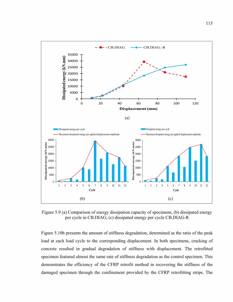
115
Figure 5.9 (a) Comparison of energy dissipation capacity of specimens, (b) dissipated energy
per cycle in CB.DIAG, (c) dissipated energy per cycle CB.DIAG-R
Figure 5.10b presents the amount of stiffness degradation, determined as the ratio of the peak
load at each load cycle to the corresponding displacement. In both specimens, cracking of
concrete resulted in gradual degradation of stiffness with displacement. The retrofitted
specimen featured almost the same rate of stiffness degradation as the control specimen. This
demonstrates the efficiency of the CFRP retrofit method in recovering the stiffness of the
damaged specimen through the confinement provided by the CFRP retrofitting strips. The
0
5000
10000
15000
20000
25000
30000
35000
0 20 40 60 80 100 120
Dis
sipa
ted
ener
gy (k
N.m
m)
Displacement (mm)
CB.DIAG CB.DIAG.-R
0
5000
10000
15000
20000
25000
30000
1 2 3 4 5 6 7 8 9 10 11 12
Dis
sip
ate
d e
ner
gy (
kN
.mm
)
Cycle
Dissipated energy per cycle
Maximum dissipated energy per applied displacement amplitude
0
5000
10000
15000
20000
25000
30000
1 2 3 4 5 6 7 8 9 10 11 12
Dis
sip
ate
d e
nergy (
kN
.mm
)
Cycle
Dissipated energy per cycle
Maximum dissipated energy per applied displacement amplitude
(a)
(b) (c)
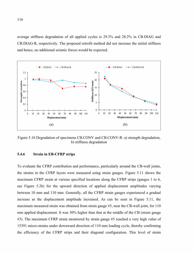
116
average stiffness degradation of all applied cycles is 29.3% and 28.2% in CB.DIAG and
CB.DIAG-R, respectively. The proposed retrofit method did not increase the initial stiffness
and hence, no additional seismic forces would be expected.
Figure 5.10 Degradation of specimens CB.CONV and CB.CONV-R: a) strength degradation,
b) stiffness degradation
5.4.6 Strain in EB-CFRP strips
To evaluate the CFRP contribution and performance, particularly around the CB-wall joints,
the strains in the CFRP layers were measured using strain gauges. Figure 5.11 shows the
maximum CFRP strain at various specified locations along the CFRP strips (gauges 1 to 6,
see Figure 5.2b) for the upward direction of applied displacement amplitudes varying
between 10 mm and 110 mm. Generally, all the CFRP strain gauges experienced a gradual
increase as the displacement amplitude increased. As can be seen in Figure 5.11, the
maximum measured strain was obtained from strain gauge #5, near the CB-wall joint, for 110
mm applied displacement. It was 30% higher than that at the middle of the CB (strain gauge
#3). The maximum CFRP strain monitored by strain gauge #5 reached a very high value of
15391 micro-strains under downward direction of 110 mm loading cycle, thereby confirming
the efficiency of the CFRP strips and their diagonal configuration. This level of strain
0
0.2
0.4
0.6
0.8
1
1.2
0 10 20 30 40 50 60 70 80 90 100 110
Str
ength
ret
enti
on
Displacement (mm)
CB.DIAG CB.DIAG-R
0
5
10
15
20
25
0 10 20 30 40 50 60 70 80 90 100 110
Sti
ffn
ess
(kN
/mm
)
Displacement (mm)
CB.DIAG CB.DIAG-R
(a) (b)
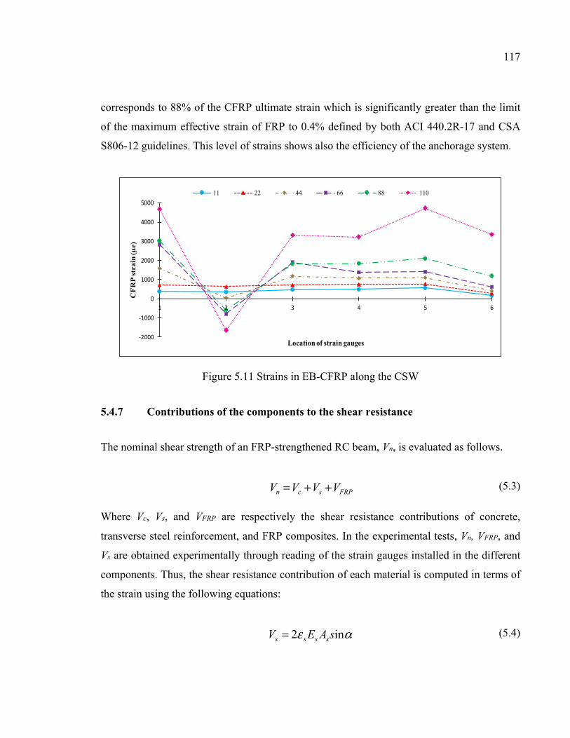
117
corresponds to 88% of the CFRP ultimate strain which is significantly greater than the limit
of the maximum effective strain of FRP to 0.4% defined by both ACI 440.2R-17 and CSA
S806-12 guidelines. This level of strains shows also the efficiency of the anchorage system.
Figure 5.11 Strains in EB-CFRP along the CSW
5.4.7 Contributions of the components to the shear resistance
The nominal shear strength of an FRP-strengthened RC beam, Vn, is evaluated as follows.
FRPscn VVVV ++= (5.3)
Where Vc, Vs, and VFRP are respectively the shear resistance contributions of concrete,
transverse steel reinforcement, and FRP composites. In the experimental tests, Vn, VFRP, and
Vs are obtained experimentally through reading of the strain gauges installed in the different
components. Thus, the shear resistance contribution of each material is computed in terms of
the strain using the following equations:
αε in2 sAEV ssss = (5.4)
-2000
-1000
0
1000
2000
3000
4000
5000
1 2 3 4 5 6
CF
RP
str
ain
(µe)
Location of strain gauges
11 22 44 66 88 110
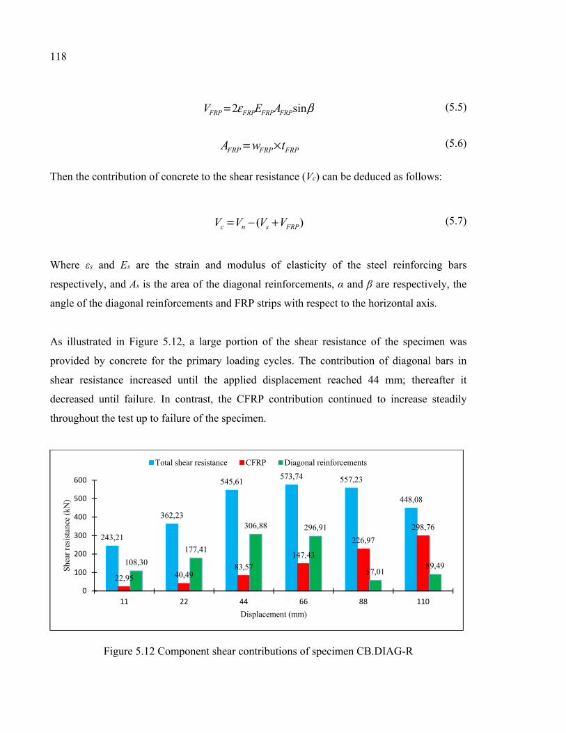
118
βε sin2 FRPFRPFRPFRP AEV = (5.5)
FRPFRPFRP twA ×= (5.6)
Then the contribution of concrete to the shear resistance (Vc) can be deduced as follows:
)( FRPsnc VVVV +−= (5.7)
Where εs and Es are the strain and modulus of elasticity of the steel reinforcing bars
respectively, and As is the area of the diagonal reinforcements, α and β are respectively, the
angle of the diagonal reinforcements and FRP strips with respect to the horizontal axis.
As illustrated in Figure 5.12, a large portion of the shear resistance of the specimen was
provided by concrete for the primary loading cycles. The contribution of diagonal bars in
shear resistance increased until the applied displacement reached 44 mm; thereafter it
decreased until failure. In contrast, the CFRP contribution continued to increase steadily
throughout the test up to failure of the specimen.
Figure 5.12 Component shear contributions of specimen CB.DIAG-R
243,21
362,23
545,61573,74 557,23
448,08
22,95 40,4983,57
147,43
226,97
298,76
108,30
177,41
306,88 296,91
57,0189,49
0
100
200
300
400
500
600
11 22 44 66 88 110
Shea
r re
sist
ance
(kN
)
Displacement (mm)
Total shear resistance CFRP Diagonal reinforcements
119
5.5 CONCLUSIONS
This paper presents an experimental investigation conducted to evaluate the cyclic
performance of a diagonally reinforced CB designed according to the latest version of the
CSA A23.3-14 standard and its seismic retrofit with EB-CFRP composites. At first the
original specimen was tested under reversed cyclic loading until failure. Then the damaged
specimen was repaired and retrofitted with EB-CFRP sheets in a diagonal configuration to
recover its seismic properties. The retrofitted specimen was also tested under cyclic loading
and the results obtained for both specimens (original versus retrofitted) were compared. This
situation simulates the case of retrofit of existing CSWs that was damaged by an earthquake
and retrofitted. The following conclusions can be drawn:
a) Generally, using EB-CFRP sheets to retrofit the CBs of CSWs has proven to be an
efficient technique since the CB not only to regain its seismic performance after damage,
but also provided more satisfactory behavior.
b) Compared to original specimen, diagonal EB-CFRP strips featured more stable
hysteretic curves and load resistance capacity.
c) The ductility of the control specimen was enhanced from 2.1 to 3.67 using diagonal EB-
CFRP sheets.
d) The amount of dissipated energy in retrofitted specimen had an incremental trend with
increase of applied displacement throughout the test. This is in contrast with the control
specimen in which the energy dissipation ability decreased with the applied
displacement augmentation from 66 mm until the completion of the test.
e) Both CB specimens exhibited almost similar stiffness degradation. While, greater
strength retention was observed in the rehabilitated specimen.
f) The substantial strain capacity of the CFRP composites confirmed that they were
actively contributed in resisting shear.
g) Beside the seismic efficiencies of the proposed rehabilitation method using diagonally
configured EB-CFRP, it applies no additional weight to the structure and it would have a
feasible installation in practice.

CHAPTER 6
NON-LINEAR TIME HISTORY ANALYSIS AND COMPARISON OF COUPLED SHEAR WALLS DESIGNED ACCORDING TO OLD AND MODERN CODES AND SEISMIC RETROFIT WITH EXTERNALLY BONDED CFRP COMPOSITES FOR
EASTERN CANADA
Sara Honarparast a and Omar Chaallal b, F.ASCE
a, b Department of Construction Engineering, École de Technologie Supérieure, 1100 Notre-Dame West, Montreal, Quebec, Canada H3C 1K3
Paper submitted in Journal of Earthquake Engineering, September, 2018
6.1 Abstract
CSWs are an efficient lateral load-resisting system. Their seismic performance depends
primarily on their CBs ability to provide adequate stiffness and strength. However, many
existing buildings with CSW resisting system were designed and constructed according to
old codes and standards with insufficient requirements for seismic design. These systems
feature unsatisfactory behaviour and prematurely collapse in case of major earthquake
events. Therefore, their seismic retrofit is urgently needed. The main objectives of this study
are, i) evaluate and compare the seismic performance of CSWs designed to old and modern
codes; ii) highlight the deficiencies of CSWs designed to old codes; iii) investigate a retrofit
method using EB-CFRP composites to enhance the seismic response of deficient CSWs. To
that end, a 20-story CSW is considered with different design details including one according
to old NBCC before 1970s and the other one designed consistent with the new NBCC 2015
and the CSA A23.3-14, for Eastern seismic Canadian zone. The nonlinear analyses of CSWs
under earthquake records are conducted in two steps. At first, the nonlinear time-history
analyses of two types of CSWs are carried out using RUAUMOKO program and the
deficiencies of old designed CSW are identified through the comparison of obtained results.
In the second step, the old design CSW is retrofitted using CFRP sheets and reanalysed to
investigate the benefits of the retrofit technique in mitigating the shortcomings. The results
indicate that CFRP retrofitting is an efficient method to enhance the seismic performance of
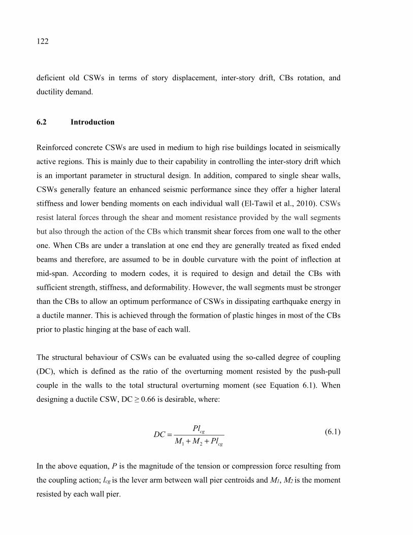
122
deficient old CSWs in terms of story displacement, inter-story drift, CBs rotation, and
ductility demand.
6.2 Introduction
Reinforced concrete CSWs are used in medium to high rise buildings located in seismically
active regions. This is mainly due to their capability in controlling the inter-story drift which
is an important parameter in structural design. In addition, compared to single shear walls,
CSWs generally feature an enhanced seismic performance since they offer a higher lateral
stiffness and lower bending moments on each individual wall (El-Tawil et al., 2010). CSWs
resist lateral forces through the shear and moment resistance provided by the wall segments
but also through the action of the CBs which transmit shear forces from one wall to the other
one. When CBs are under a translation at one end they are generally treated as fixed ended
beams and therefore, are assumed to be in double curvature with the point of inflection at
mid-span. According to modern codes, it is required to design and detail the CBs with
sufficient strength, stiffness, and deformability. However, the wall segments must be stronger
than the CBs to allow an optimum performance of CSWs in dissipating earthquake energy in
a ductile manner. This is achieved through the formation of plastic hinges in most of the CBs
prior to plastic hinging at the base of each wall.
The structural behaviour of CSWs can be evaluated using the so-called degree of coupling
(DC), which is defined as the ratio of the overturning moment resisted by the push-pull
couple in the walls to the total structural overturning moment (see Equation 6.1). When
designing a ductile CSW, DC ≥ 0.66 is desirable, where:
cg
cg
PlMM
PlDC
++=
21
(6.1)
In the above equation, P is the magnitude of the tension or compression force resulting from
the coupling action; lcg is the lever arm between wall pier centroids and M1, M2 is the moment
resisted by each wall pier.
123
Many existing buildings with CSWs lateral load resisting systems were designed and
constructed according to old design codes and standards i.e., before 1970’s. Substantial
advancements have been achieved in the last decades. Most of this progress has been adopted
by modern codes and standards to increase safety and to optimize the seismic design of
structural elements. In view of the crucial progress and the lack of seismic provisions in old
design codes, CSWs designed to old codes are still at risk of damage or collapse in probable
moderate to strong earthquakes. Insufficient stiffness, inadequate flexural and shear
capacities, poor concrete confinement, neglecting the crucial concept of strong walls-weak
CBs that allows the desired sequence of plastic hinge formation, inadequate lap splices of the
longitudinal reinforcement located at the plastic hinge region, and insufficient embedment
length of CB reinforcements into the walls are some of the anticipated deficiencies in case of
seismic event.
During the past decades, some nonlinear analyses were carried out to investigate the seismic
performance of CSWs (Harries, 1995; McNeice, 2004; Boivin, 2006; Xuan, 2006; Benazza,
2012).
Harries (1995) studied the seismic behavior of four 18-story fully coupled and partially CSW
systems designed according to NBCC 1995 and located in Vancouver (Western Canada). The
CBs of the prototype structures included embedded steel CBs designed according to CSA
S16.1 M94 and RC CBs designed according to CSA A23.3-M94. The CBs were 4 m and 1.3
m long in partially and fully coupled wall system, respectively. The RC CBs were designed
with conventional reinforcement layout for partially CSW and with diagonal reinforcement
for fully CSW. The computer program DRAIN-2DX was used for the non-linear dynamic
analyses of the structures under earthquakes excitations. The author concluded that compared
to RC CBs, the structures coupled with embedded steel beams exhibited greater energy
dissipation, smaller lateral displacements, and enhanced ductility without significant loss of
strength or stiffness.
124
Mc.Neice (2004) conducted an investigation about the performance-based design method
through non-linear dynamic analyses for a 30-story coupled core wall structure designed
according to the 2003 International Building Code (IBC, 2003) with reference to ASCE 7-02
(ASCE, 2002). Xuan (2006) performed a nonlinear analysis of a 15-story coupled core wall
with diagonally reinforced CBs designed according to the provisions of NEHRP 2000, ACI
318-02, and FEMA 356 to investigate the applicability and validity of the performance-based
design method. Boivin & Paultre (2010) also studied the seismic performance of a 12-story
core wall of an office building designed according to the NBCC 2005 and CSA 2004.
Benazza (2012) studied the seismic performance of 10, 20, and 30-story CSWs designed
according to NBCC 2010 and CSA A23.3-04.
It is noted that none of the above-mentioned studies has investigated the nonlinear seismic
response of existing CSWs designed and constructed before 1970s. In addition, given the
important the evolution of modern seismic design codes and standards, the seismic retrofit of
existing RC CSWs designed to old codes is inevitable. Various repair and retrofit schemes
were proposed to mitigate the deficiencies of the CBs and the walls piers of existing CSWs.
Bonding steel plates to one side of the CB (Harries, 1995), upgrading the degree of coupling
by adding an optimized number of deep CBs (Chaallal & Nollet, 1997), and bolting steel
plates onto the side faces of the CBs with or without adding a buckling restraint device to
control plate buckling (Su & Zhu, 2005; Su & Cheng, 2011) are some of the retrofitting
techniques deal with the strengthening of the existing CSWs. Some alternative designs for
CBs have also been proposed. They include steel CBs with and without stiffeners (Harries,
1995), concrete-filled steel tube CBs (Teng et al., 1999), steel coupling I-beams encased in
reinforced concrete members (Gong & Shahrooz, 2001a, 2001b; Motter et al., 2012), and
embedded steel composite CBs with shear studs (Lam et al., 2005). Although these
techniques are effective in enhancing the seismic response of structures, they may alter the
distribution of lateral loads on the building by adding more weight to the structure (Lombard
et al., 2000). The drawbacks of each of the proposed retrofit methods can be found in
Honarparast & Chaallal (2015).
125
In recent years, the use of EB-FRP has emerged as a viable, cost effective and minimally
disruptive seismic retrofit for RC structural elements. FRP composites offer very desirable
properties such as ease of application, high strength to weight ratio, and high resistance to
corrosion. The effectiveness of using EB-FRP retrofit method for shear and flexural
strengthening of individual shear walls was investigated in previous research studies
(Lombard et al., 2000; Antoniades et al., 2003; Paterson & Mitchell, 2003; Hiotakis, 2004;
Khalil & Ghobarah, 2005). The FRP composites have also used in frames especially for the
beam-column joints (Liu, 2001; Quintana-Gallo, 2014; Hadi & Tran, 2016). The efficiency
of EB-FRP retrofit method to enhance the seismic behavior of CSWs was studied in
Arabzadeh & Galal (2017) through a nonlinear time history analysis of a 12-story C-shaped
wall but designed according to recent code and Standards (NBCC 2005 and CSA A23.3-04).
None of the previous studies dealt with the retrofit of existing CSWs designed according to
codes prior to 1970s. This has been the main impetus to carry out the research study to
investigate the seismic performance of such CSWs retrofitted using EB-CFRP. Different
aspects including the seismic performance of CSWs designed to old and modern codes as
well as the effect of a new retrofit method using CFRP composites on the seismic behavior of
old CSWs are considered. To that end, two 20-story CSWs are considered: one designed
according to old code, NBCC 1941, while the other one was designed according to NBCC
2015 code and CSA A23.3-14 Standard. The 1941 code was as representative of codes prior
to 1970s since there were no significant changes in the codes prior to the 1970s for the design
of reinforced concrete walls and beams. Therefore, most of the old-designed and constructed
CBs have similar deficiencies such as inadequate anchorage length, insufficient stirrups,
inadequate stirrup spacing. It may be worth adding that many RC building structures contain
CSWs designed to old codes in Canada and were built during 1940 to 1970 period. These
structures are still in use and are being retrofitted to conform to new modern standards. The
city of Montreal is selected for the location of the CSWs as a representative of Eastern
seismic region of Canada. Eleven earthquake records are selected and scaled being
compatible with the target spectral acceleration as will be seen later. Nonlinear time history
analyses of these CSWs under simulated ground motions are conducted using RUAUMOKO
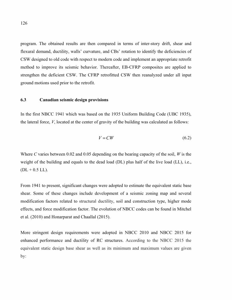
126
program. The obtained results are then compared in terms of inter-story drift, shear and
flexural demand, ductility, walls’ curvature, and CBs’ rotation to identify the deficiencies of
CSW designed to old code with respect to modern code and implement an appropriate retrofit
method to improve its seismic behavior. Thereafter, EB-CFRP composites are applied to
strengthen the deficient CSW. The CFRP retrofitted CSW then reanalyzed under all input
ground motions used prior to the retrofit.
6.3 Canadian seismic design provisions
In the first NBCC 1941 which was based on the 1935 Uniform Building Code (UBC 1935),
the lateral force, V, located at the center of gravity of the building was calculated as follows:
CWV = (6.2)
Where C varies between 0.02 and 0.05 depending on the bearing capacity of the soil, W is the
weight of the building and equals to the dead load (DL) plus half of the live load (LL), i.e.,
(DL + 0.5 LL).
From 1941 to present, significant changes were adopted to estimate the equivalent static base
shear. Some of these changes include development of a seismic zoning map and several
modification factors related to structural ductility, soil and construction type, higher mode
effects, and force modification factor. The evolution of NBCC codes can be found in Mitchel
et al. (2010) and Honarparat and Chaallal (2015).
More stringent design requirements were adopted in NBCC 2010 and NBCC 2015 for
enhanced performance and ductility of RC structures. According to the NBCC 2015 the
equivalent static design base shear as well as its minimum and maximum values are given
by:
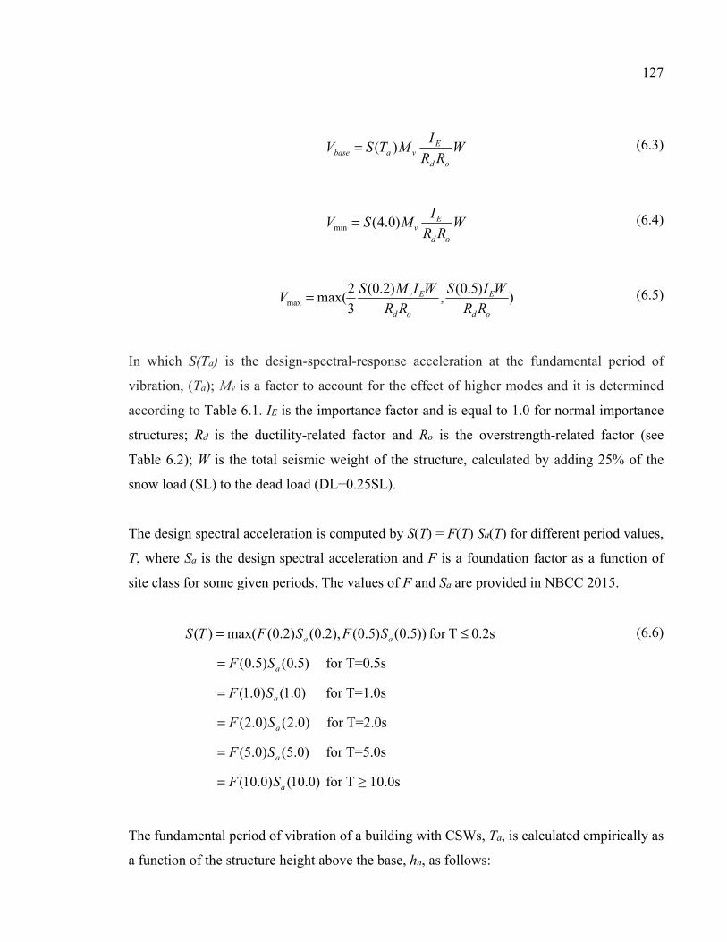
127
W
RR
IMTSV
od
Evabase )(= (6.3)
W
RR
IMSV
od
Ev)0.4(min = (6.4)
)
)5.0(,
)2.0(
3
2max(max
od
E
od
Ev
RR
WIS
RR
WIMSV = (6.5)
In which S(Ta) is the design-spectral-response acceleration at the fundamental period of
vibration, (Ta); Mv is a factor to account for the effect of higher modes and it is determined
according to Table 6.1. IE is the importance factor and is equal to 1.0 for normal importance
structures; Rd is the ductility-related factor and Ro is the overstrength-related factor (see
Table 6.2); W is the total seismic weight of the structure, calculated by adding 25% of the
snow load (SL) to the dead load (DL+0.25SL).
The design spectral acceleration is computed by S(T) = F(T) Sa(T) for different period values,
T, where Sa is the design spectral acceleration and F is a foundation factor as a function of
site class for some given periods. The values of F and Sa are provided in NBCC 2015.
0.2sTfor ))5.0()5.0(),2.0()2.0(max()( ≤= aa SFSFTS
)5.0()5.0( aSF= for T=0.5s
)0.1()0.1( aSF= for T=1.0s
)0.2()0.2( aSF= for T=2.0s
)0.5()0.5( aSF= for T=5.0s
)0.10()0.10( aSF= for T ≥ 10.0s
(6.6)
The fundamental period of vibration of a building with CSWs, Ta, is calculated empirically as
a function of the structure height above the base, hn, as follows:
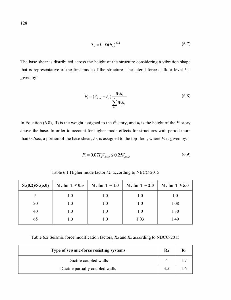
128
4/3)(05.0 na hT = (6.7)
The base shear is distributed across the height of the structure considering a vibration shape
that is representative of the first mode of the structure. The lateral force at floor level i is
given by:
=
−= n
iii
iitbasei
hW
hWFVF
1
)( (6.8)
In Equation (6.8), Wi is the weight assigned to the ith story, and hi is the height of the ith story
above the base. In order to account for higher mode effects for structures with period more
than 0.7sec, a portion of the base shear, Ft, is assigned to the top floor, where Ft is given by:
basebaseat VVTF 25.007.0 ≤= (6.9)
Table 6.1 Higher mode factor Mv according to NBCC-2015
Sa(0.2)/Sa(5.0) Mv for T ≤ 0.5 Mv for T = 1.0 Mv for T = 2.0 Mv for T ≥ 5.0
5
20
40
65
1.0
1.0
1.0
1.0
1.0
1.0
1.0
1.0
1.0
1.0
1.0
1.03
1.0
1.08
1.30
1.49
Table 6.2 Seismic force modification factors, Rd and Ro according to NBCC-2015
Type of seismic-force resisting systems Rd Ro
Ductile coupled walls 4 1.7
Ductile partially coupled walls 3.5 1.6
129
6.4 CSA standard A23.3-14 provisions for the design of CSWs
Prior to the first CSA standard published in 1959, there were some requirements in NBCC
code for the design of RC walls. However, there was no specific provisions for CSWs nor for
CBs. The first design requirements of CSWs were adopted in CSA A23.3-M84. Through the
evolution of seismic design codes in Canada, significant improvements were achieved in the
design and detailing requirements according to the CSA standards linked to seismic force
modification factors, Rd and Ro. In CSA A23.3-14 (CSA 2014), some seismic design
requirements were provided for shear and flexural strength design of ductile CSWs and
partially ductile CSWs.
To ensure ductility of coupled systems, the inelastic rotational capacity of both the walls and
the CBs shall be greater than their respective inelastic rotational demands. Thus, the inelastic
rotational demand (θid) on coupled walls and CBs are calculated using the Equations 6.10 and
6.11, respectively.
004.0≥
Δ=
w
dofid h
RRθ (6.10)
u
cg
w
dofid l
l
h
RR
Δ=θ (6.11)
Where ∆f is the deflection of the top of a wall due to the effect of factored loads and ∆f RoRd is
the design displacement. hw is the height of the wall, lcg is the horizontal distance between the
centroids of walls on either side of coupling beam, and lu is the length of the clear span.
The inelastic rotational capacity of CBs, θic, shall be taken as 0.04 and 0.02 for diagonally
reinforced and conventionally reinforced CBs, respectively. The maximum inelastic
rotational capacity should not be greater than 0.025 for wall elements.
130
According to CSA A23.3-14, the factored moment resistance of the walls shall exceed the
moment resulting from the nominal resistance of the CBs and the factored design moment in
the wall. Thus, to satisfy the capacity design requirement, the factored wall moments at each
level is increased by the wall over-strength factor, γ. The wall over-strength factor is the ratio
of the sum of the nominal shear capacities of the CBs, Vn, to the sum of the factored shear in
CBs due to lateral loading, Vf, and that is:
=
f
n
V
Vγ
(6.12)
The detailing characteristics of the coupled walls dealing with walls and CBs geometry,
reinforcement layout in diagonal and conventional configuration, stirrups spacing, anchorage
length of CB reinforcements into the walls, and the amount of wall reinforcements in plastic
hinge region and out of it have been specified in CSA A23.3-14. New Canadian standards
provide provisions to design new CSWs and distinguish between two types (conventional or
diagonal configuration) of CBs depending on the shear stress level resulting from the
factored loads. CBs with conventional reinforcement are allowed by CSA A23.3-14 only if
the shear stress resulting from factored loads is less than cu fdl ′)/(1.0 , where lu is the clear
span, d the effective depth, and cf ′ the concrete compressive strength. However, Prior to the
CSA A23.3-M84 (1984) standard, all CBs were designed and constructed with
conventionally reinforcement layout and the concept of diagonally reinforced CB was not yet
adopted in practice. While, for seismic loading most CBs fall into the diagonal reinforcement
category.
6.5 Description of studied building
In this study, a 20-story RC office building with CSW lateral load resisting system in the
north-south direction, located in Montreal and founded on soil type C (according to the
NBCC 2015) was considered. The plan of the building and elevation view of the CSWs are
shown in Figure 6.1. The building consists of a 20 m by 30 m floor plate of 200 mm thick
131
slab, columns with section of 600×600 mm, and two CSWs in Axes B and E (Figure 6.1).
The story floor-to-floor heights are 3.5 m and hence the total height of the building is 70 m.
Two CSWs were designed and analyzed. The first, hereafter called CSW1941, was designed
according to NBCC 1941, and is representative of the old existing CSWs. The second one,
hereafter called CSW2015, was designed and detailed according to modern NBCC 2015 code
and CSA A23.3-14 Standard. The CSWs carry 100% of the lateral loads applied to the
structure. The walls and columns carry gravity loads based on their tributary areas. The
structure is made of normal-density concrete with a compressive strength of 25 MPa and 30
MPa respectively for CSW1941 and CSW2015 and steel reinforcement with a yield strength
of 400 MPa. The walls have a cross section of 3 m × 0.35 m and are connected at the level of
each floor by 700 mm deep and 350 mm wide CBs, i.e., a span to depth ratio of 2.86.
The computer program SAP 2000 (V19) was used for the initial elastic static analysis in
order to determine the design forces of the walls and CBs. The lateral forces resulting from
distribution of equivalent static base shear were applied at each story level. Then, based on
the obtained design values from analyses, the walls and CBs were designed and detailed
according to respective standard requirements.
Figure 6.2 and Figure 6.3 present the geometry and reinforcement details of wall segment
and CBs for CSW1941 and CSW2015 at different story levels. Conventionally reinforced
CBs were considered for CSW1941 (see Figure 6.2), whereas diagonally reinforced CBs at
different story levels were considered in CSW2015 (see Figure 6.3). Furthermore, in
CSW2015, the walls were designed according to the requirements of CSA A23.3-14 for
plastic hinge region and other regions. According to CSA A23.3-14 Standard, the minimum
height of the plastic hinge region is given by:
wwp hlh 1.05.0 += (6.13)
Since for the studied building the length of CSW (lw) and its height (hw) are 8 m and 70 m,
respectively, the lower first four stories of the walls are detailed as a plastic hinge region.
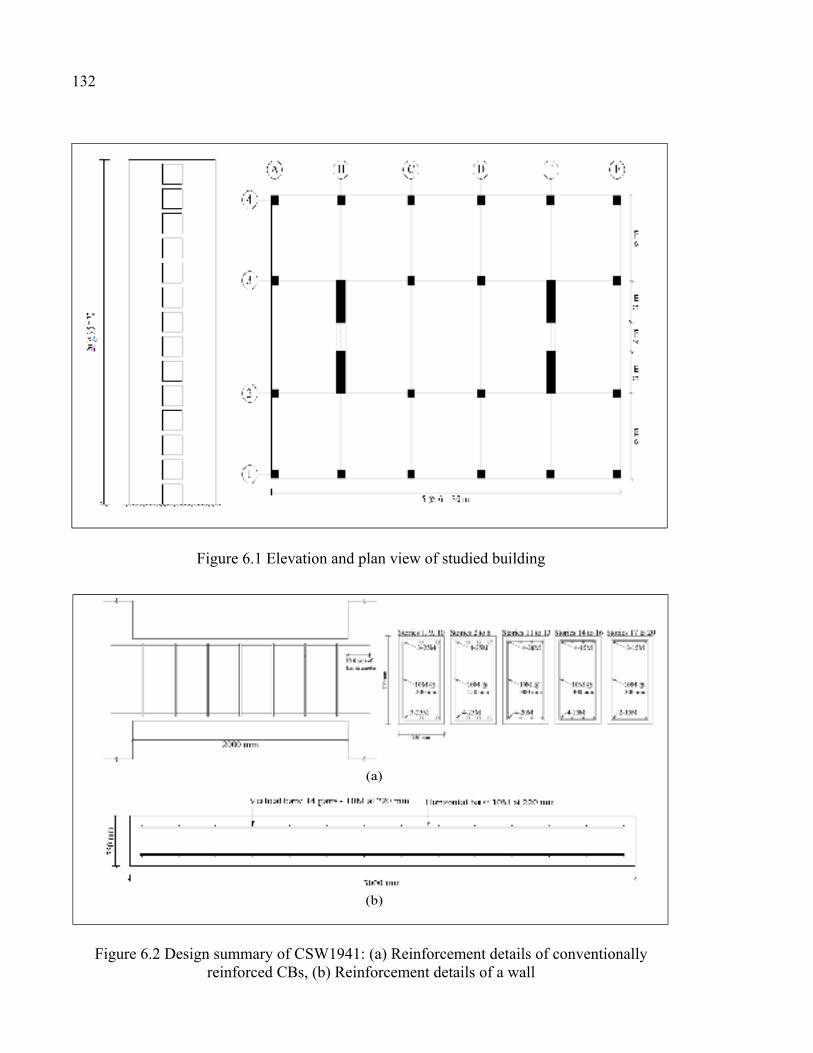
132
Figure 6.1 Elevation and plan view of studied building
Figure 6.2 Design summary of CSW1941: (a) Reinforcement details of conventionally reinforced CBs, (b) Reinforcement details of a wall
(a)
(b)
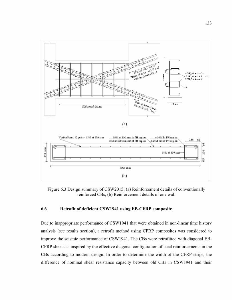
133
Figure 6.3 Design summary of CSW2015: (a) Reinforcement details of conventionally reinforced CBs, (b) Reinforcement details of one wall
6.6 Retrofit of deficient CSW1941 using EB-CFRP composite
Due to inappropriate performance of CSW1941 that were obtained in non-linear time history
analysis (see results section), a retrofit method using CFRP composites was considered to
improve the seismic performance of CSW1941. The CBs were retrofitted with diagonal EB-
CFRP sheets as inspired by the effective diagonal configuration of steel reinforcements in the
CBs according to modern design. In order to determine the width of the CFRP strips, the
difference of nominal shear resistance capacity between old CBs in CSW1941 and their
(a)
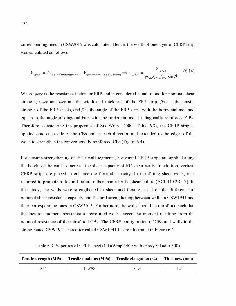
134
corresponding ones in CSW2015 was calculated. Hence, the width of one layer of CFRP strip
was calculated as follows:
βϕ sin)(
)() () ()(FRPFRPFRP
FRPiFRPibeamscouplingalconventionibeamscouplingdiagonaliFRPi ft
VwVVV =−= (6.14)
Where φFRP is the resistance factor for FRP and is considered equal to one for nominal shear
strength, wFRP and tFRP are the width and thickness of the FRP strip, fFRP is the tensile
strength of the FRP sheets, and β is the angle of the FRP strips with the horizontal axis and
equals to the angle of diagonal bars with the horizontal axis in diagonally reinforced CBs.
Therefore, considering the properties of SikaWrap 1400C (Table 6.3), the CFRP strip is
applied onto each side of the CBs and in each direction and extended to the edges of the
walls to strengthen the conventionally reinforced CBs (Figure 6.4).
For seismic strengthening of shear wall segments, horizontal CFRP strips are applied along
the height of the wall to increase the shear capacity of RC shear walls. In addition, vertical
CFRP strips are placed to enhance the flexural capacity. In retrofitting shear walls, it is
required to promote a flexural failure rather than a brittle shear failure (ACI 440.2R-17). In
this study, the walls were strengthened in shear and flexure based on the difference of
nominal shear resistance capacity and flexural strengthening between walls in CSW1941 and
their corresponding ones in CSW2015. Furthermore, the walls should be retrofitted such that
the factored moment resistance of retrofitted walls exceed the moment resulting from the
nominal resistance of the retrofitted CBs. The CFRP configuration of CBs and walls in the
strengthened CSW1941, hereafter called CSW1941-R, are illustrated in Figure 6.4.
Table 6.3 Properties of CFRP sheet (SikaWrap 1400 with epoxy Sikadur 300)
Tensile strength (MPa) Tensile modulus (MPa) Tensile elongation (%) Thickness (mm)
1355 115700 0.95 1.3
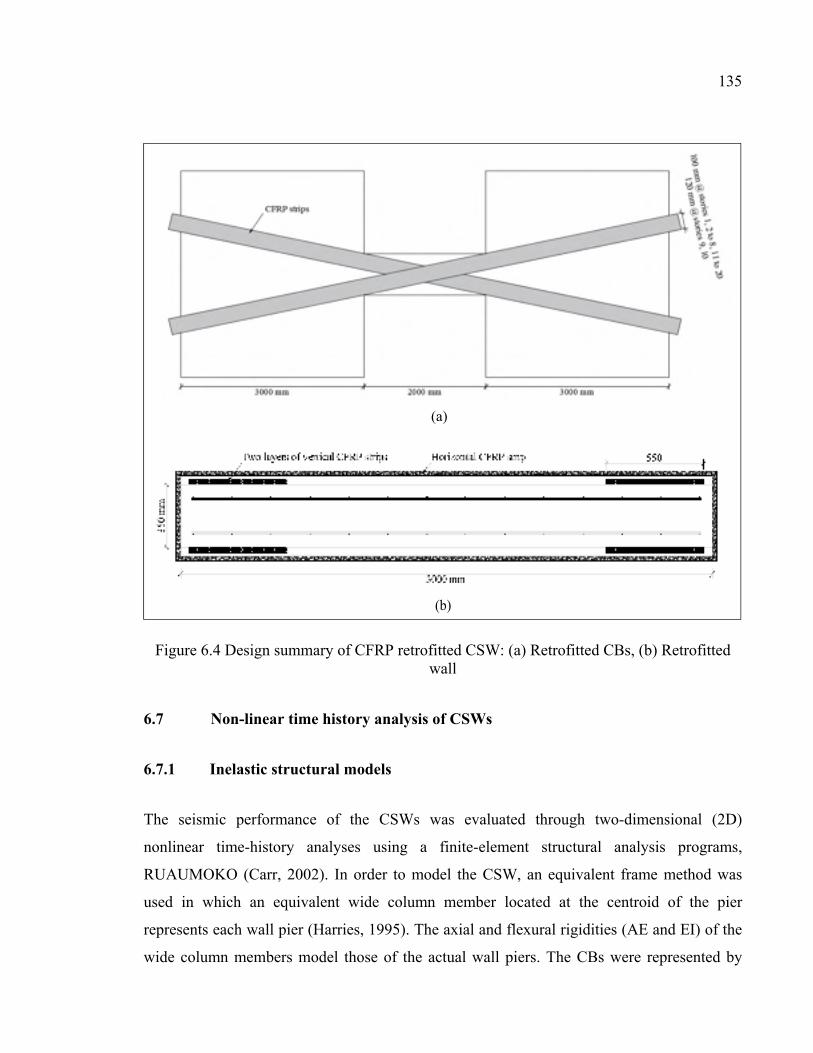
135
Figure 6.4 Design summary of CFRP retrofitted CSW: (a) Retrofitted CBs, (b) Retrofitted wall
6.7 Non-linear time history analysis of CSWs
6.7.1 Inelastic structural models
The seismic performance of the CSWs was evaluated through two-dimensional (2D)
nonlinear time-history analyses using a finite-element structural analysis programs,
RUAUMOKO (Carr, 2002). In order to model the CSW, an equivalent frame method was
used in which an equivalent wide column member located at the centroid of the pier
represents each wall pier (Harries, 1995). The axial and flexural rigidities (AE and EI) of the
wide column members model those of the actual wall piers. The CBs were represented by
(b)
(a)
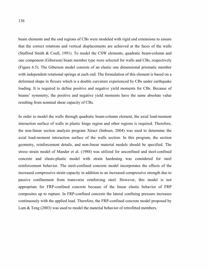
136
beam elements and the end regions of CBs were modeled with rigid end extensions to ensure
that the correct rotations and vertical displacements are achieved at the faces of the walls
(Stafford Smith & Coull, 1991). To model the CSW elements, quadratic beam-column and
one component (Giberson) beam member type were selected for walls and CBs, respectively
(Figure 6.5). The Giberson model consists of an elastic one dimensional prismatic member
with independent rotational springs at each end. The formulation of this element is based on a
deformed shape in flexure which is a double curvature experienced by CBs under earthquake
loading. It is required to define positive and negative yield moments for CBs. Because of
beams’ symmetry, the positive and negative yield moments have the same absolute value
resulting from nominal shear capacity of CBs.
In order to model the walls through quadratic beam-column element, the axial load-moment
interaction surface of walls in plastic hinge region and other regions is required. Therefore,
the non-linear section analysis program Xtract (Imbsen, 2004) was used to determine the
axial load-moment interaction surface of the walls section. In this program, the section
geometry, reinforcement details, and non-linear material models should be specified. The
stress–strain model of Mander et al. (1988) was utilized for unconfined and steel-confined
concrete and elasto-plastic model with strain hardening was considered for steel
reinforcement behavior. The steel-confined concrete model incorporates the effects of the
increased compressive strain capacity in addition to an increased compressive strength due to
passive confinement from transverse reinforcing steel. However, this model is not
appropriate for FRP-confined concrete because of the linear elastic behavior of FRP
composites up to rupture. In FRP-confined concrete the lateral confining pressure increases
continuously with the applied load. Therefore, the FRP-confined concrete model proposed by
Lam & Teng (2003) was used to model the material behavior of retrofitted members.
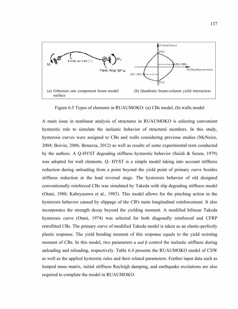
137
Figure 6.5 Types of elements in RUAUMOKO: (a) CBs model, (b) walls model
A main issue in nonlinear analysis of structures in RUAUMOKO is selecting convenient
hysteretic rule to simulate the inelastic behavior of structural members. In this study,
hysteresis curves were assigned to CBs and walls considering previous studies (McNeice,
2004; Boivin, 2006; Benazza, 2012) as well as results of some experimental tests conducted
by the authors. A Q-HYST degrading stiffness hysteretic behavior (Saiidi & Sozen, 1979)
was adopted for wall elements. Q- HYST is a simple model taking into account stiffness
reduction during unloading from a point beyond the yield point of primary curve besides
stiffness reduction at the load reversal stage. The hysteresis behavior of old designed
conventionally reinforced CBs was simulated by Takeda with slip degrading stiffness model
(Otani, 1980; Kabeyasawa et al., 1983). This model allows for the pinching action in the
hysteresis behavior caused by slippage of the CB's main longitudinal reinforcement. It also
incorporates the strength decay beyond the yielding moment. A modified bilinear Takeda
hysteresis curve (Otani, 1974) was selected for both diagonally reinforced and CFRP
retrofitted CBs. The primary curve of modified Takeda model is taken as an elastic-perfectly
plastic response. The yield bending moment of this response equals to the yield resisting
moment of CBs. In this model, two parameters α and β control the inelastic stiffness during
unloading and reloading, respectively. Table 6.4 presents the RUAUMOKO model of CSW
as well as the applied hysteretic rules and their related parameters. Further input data such as
lumped mass matrix, initial stiffness Rayleigh damping, and earthquake excitations are also
required to complete the model in RUAUMOKO.
(a) Giberson one component beam model (b) Quadratic beam-column yield interactionsurface
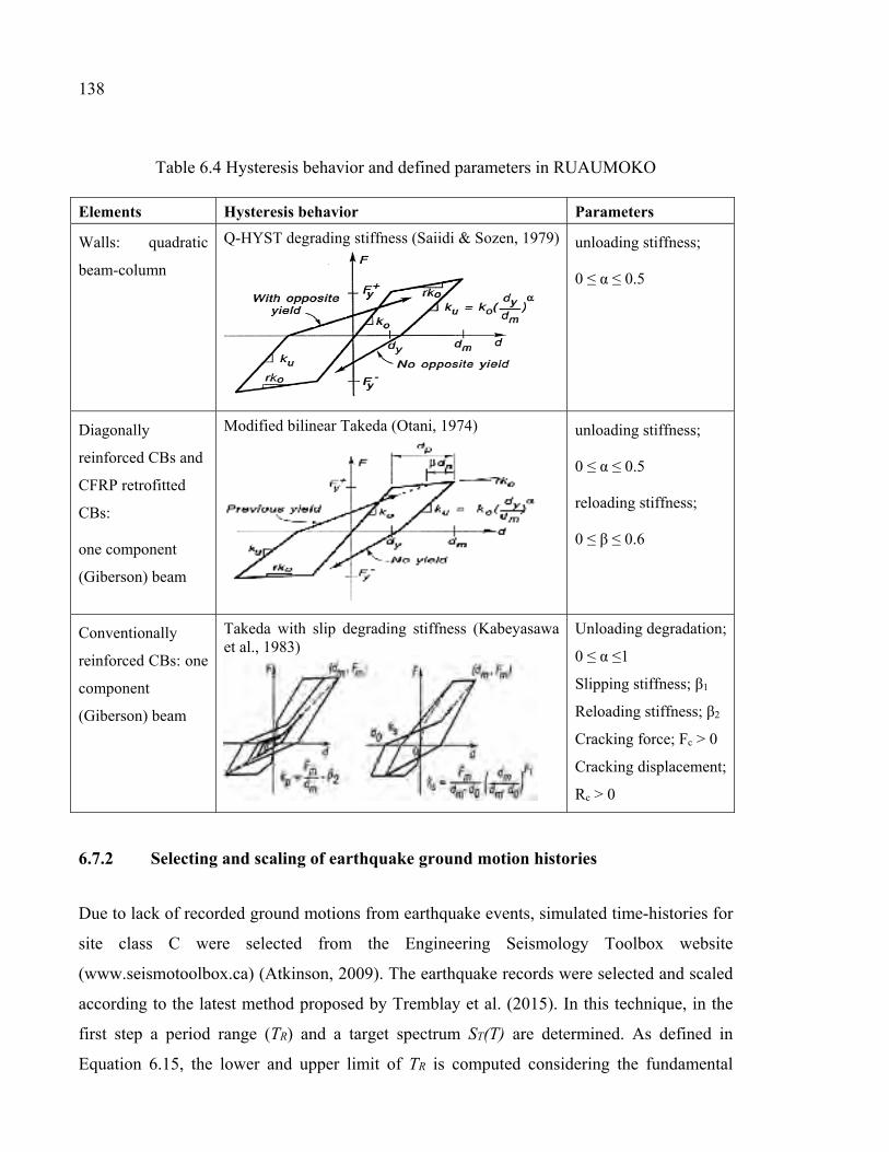
138
Table 6.4 Hysteresis behavior and defined parameters in RUAUMOKO Elements Hysteresis behavior Parameters
Walls: quadratic
beam-column
Q-HYST degrading stiffness (Saiidi & Sozen, 1979)
unloading stiffness;
0 ≤ α ≤ 0.5
Diagonally
reinforced CBs and
CFRP retrofitted
CBs:
one component
(Giberson) beam
Modified bilinear Takeda (Otani, 1974)
unloading stiffness;
0 ≤ α ≤ 0.5
reloading stiffness;
0 ≤ β ≤ 0.6
Conventionally
reinforced CBs: one
component
(Giberson) beam
Takeda with slip degrading stiffness (Kabeyasawa et al., 1983)
Unloading degradation;
0 ≤ α ≤1
Slipping stiffness; β1
Reloading stiffness; β2
Cracking force; Fc > 0
Cracking displacement;
Rc > 0
6.7.2 Selecting and scaling of earthquake ground motion histories
Due to lack of recorded ground motions from earthquake events, simulated time-histories for
site class C were selected from the Engineering Seismology Toolbox website
(www.seismotoolbox.ca) (Atkinson, 2009). The earthquake records were selected and scaled
according to the latest method proposed by Tremblay et al. (2015). In this technique, in the
first step a period range (TR) and a target spectrum ST(T) are determined. As defined in
Equation 6.15, the lower and upper limit of TR is computed considering the fundamental
139
period of the structure (T) and the period of the highest vibration mode required to cumulate
a minimum participating mass of 90% of the structure mass (T90%) as follows:
]5.1 ,0.2max[ ]; ,2.0min[ max%90min sTTTTT == (6.15)
The target spectrum is defined for the location and soil type according to NBCC 2015. Figure
6.6 illustrates the target spectrum for soil type C in Montreal.
In the second step, appropriate ground motions should be selected from the accelerograms
developed by Atkinson (2009). There are four sets of 45 simulated earthquake time-histories
with magnitude of 6 and 7 for Eastern Canada. As shown in Table 6.5, two scenarios
including five ground motions with magnitude of 6 (M6) and six ground motions of M7 were
considered. In order to select the proper earthquake records compatible with target spectral,
the mean and standard deviation are calculated for the ratio of target spectral amplitude
(ST(T)) to the ground motions spectral amplitude (Sg(T)) over the corresponding scenario
period. Then, the records with lowest standard deviation and a mean between 0.5 and 2.0 are
selected. The mean value of ST(T)/Sg(T) ratio of each selected ground motion is its scale
factor (SF1).
In the final step, the selected ground motions are multiplied by their corresponding scaling
factor. After that, the mean response spectra of each suite of scaled earthquakes are computed
within each scenario-specific period range. If it falls more than 10% below the ST(T), a
second scale factor (SF2) is calculated so that the difference between the mean Sg(T) of the
scaled records and ST(T) reaches the allowable limit of 10% (Figure 6.6 d). The final scale
factor SF equals to (SF1 × SF2).
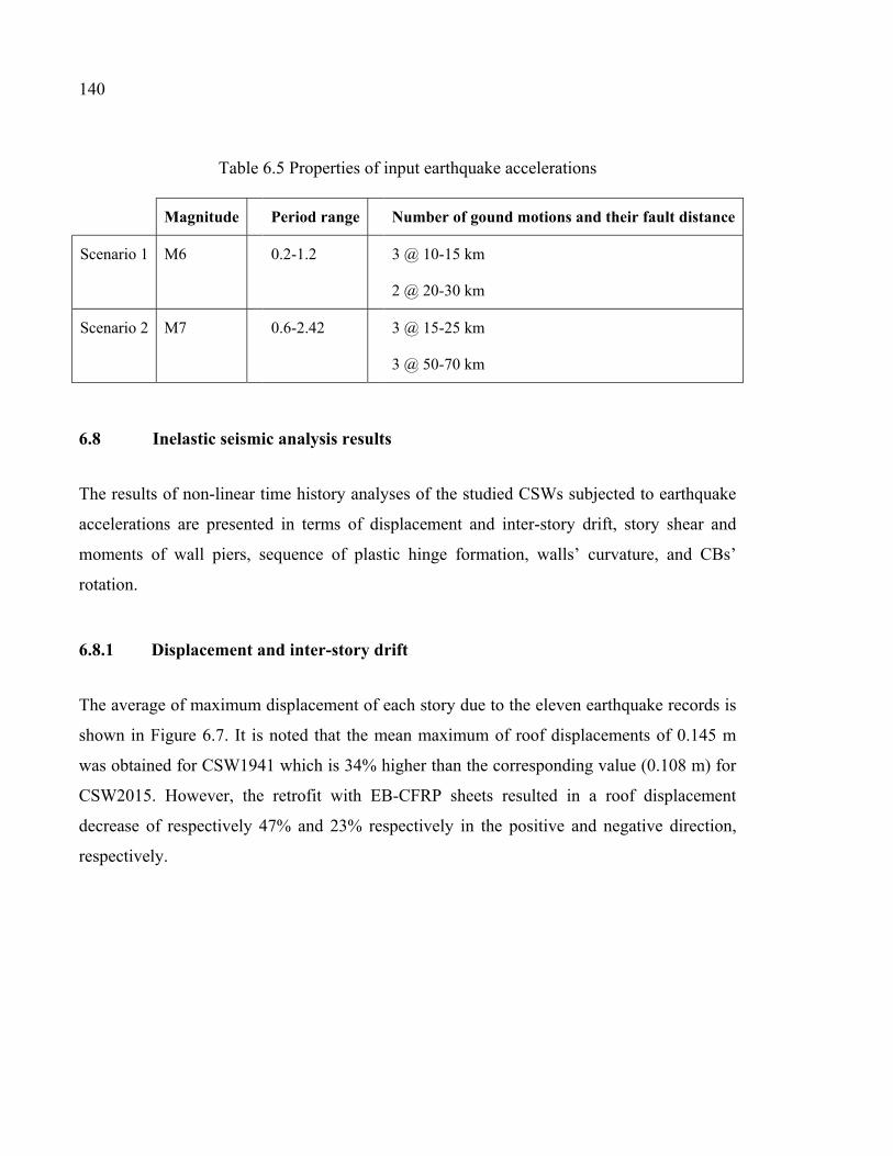
140
Table 6.5 Properties of input earthquake accelerations
Magnitude Period range Number of gound motions and their fault distance
Scenario 1 M6 0.2-1.2 3 @ 10-15 km
2 @ 20-30 km
Scenario 2 M7 0.6-2.42 3 @ 15-25 km
3 @ 50-70 km
6.8 Inelastic seismic analysis results
The results of non-linear time history analyses of the studied CSWs subjected to earthquake
accelerations are presented in terms of displacement and inter-story drift, story shear and
moments of wall piers, sequence of plastic hinge formation, walls’ curvature, and CBs’
rotation.
6.8.1 Displacement and inter-story drift
The average of maximum displacement of each story due to the eleven earthquake records is
shown in Figure 6.7. It is noted that the mean maximum of roof displacements of 0.145 m
was obtained for CSW1941 which is 34% higher than the corresponding value (0.108 m) for
CSW2015. However, the retrofit with EB-CFRP sheets resulted in a roof displacement
decrease of respectively 47% and 23% respectively in the positive and negative direction,
respectively.
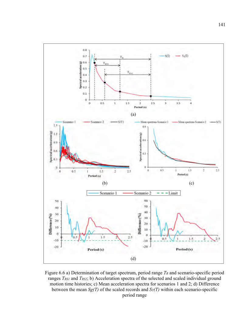
141
Figure 6.6 a) Determination of target spectrum, period range TR and scenario-specific period ranges TRS1 and TRS2; b) Acceleration spectra of the selected and scaled individual ground motion time histories; c) Mean acceleration spectra for scenarios 1 and 2; d) Difference between the mean Sg(T) of the scaled records and ST(T) within each scenario-specific
period range
(d)
(b) (c)
(a)
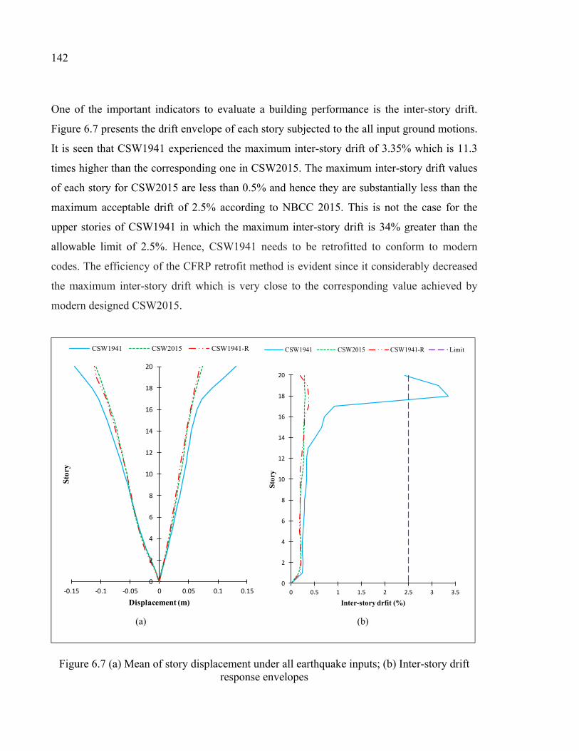
142
One of the important indicators to evaluate a building performance is the inter-story drift.
Figure 6.7 presents the drift envelope of each story subjected to the all input ground motions.
It is seen that CSW1941 experienced the maximum inter-story drift of 3.35% which is 11.3
times higher than the corresponding one in CSW2015. The maximum inter-story drift values
of each story for CSW2015 are less than 0.5% and hence they are substantially less than the
maximum acceptable drift of 2.5% according to NBCC 2015. This is not the case for the
upper stories of CSW1941 in which the maximum inter-story drift is 34% greater than the
allowable limit of 2.5%. Hence, CSW1941 needs to be retrofitted to conform to modern
codes. The efficiency of the CFRP retrofit method is evident since it considerably decreased
the maximum inter-story drift which is very close to the corresponding value achieved by
modern designed CSW2015.
Figure 6.7 (a) Mean of story displacement under all earthquake inputs; (b) Inter-story drift response envelopes
0
2
4
6
8
10
12
14
16
18
20
-0.15 -0.1 -0.05 0 0.05 0.1 0.15
Stor
y
Displacement (m)
CSW1941 CSW2015 CSW1941-R
0
2
4
6
8
10
12
14
16
18
20
0 0.5 1 1.5 2 2.5 3 3.5
Sto
ry
Inter-story drfit (%)
CSW1941 CSW2015 CSW1941-R Limit
(a) (b)
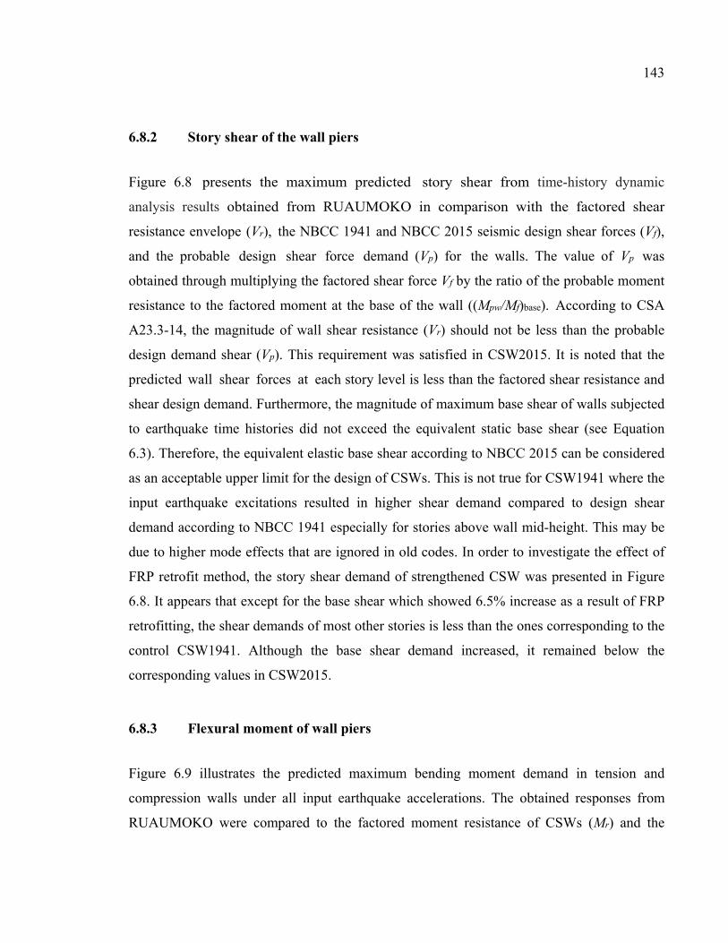
143
6.8.2 Story shear of the wall piers
Figure 6.8 presents the maximum predicted story shear from time-history dynamic
analysis results obtained from RUAUMOKO in comparison with the factored shear
resistance envelope (Vr), the NBCC 1941 and NBCC 2015 seismic design shear forces (Vf),
and the probable design shear force demand (Vp) for the walls. The value of Vp was
obtained through multiplying the factored shear force Vf by the ratio of the probable moment
resistance to the factored moment at the base of the wall ((Mpw/Mf)base). According to CSA
A23.3-14, the magnitude of wall shear resistance (Vr) should not be less than the probable
design demand shear (Vp). This requirement was satisfied in CSW2015. It is noted that the
predicted wall shear forces at each story level is less than the factored shear resistance and
shear design demand. Furthermore, the magnitude of maximum base shear of walls subjected
to earthquake time histories did not exceed the equivalent static base shear (see Equation
6.3). Therefore, the equivalent elastic base shear according to NBCC 2015 can be considered
as an acceptable upper limit for the design of CSWs. This is not true for CSW1941 where the
input earthquake excitations resulted in higher shear demand compared to design shear
demand according to NBCC 1941 especially for stories above wall mid-height. This may be
due to higher mode effects that are ignored in old codes. In order to investigate the effect of
FRP retrofit method, the story shear demand of strengthened CSW was presented in Figure
6.8. It appears that except for the base shear which showed 6.5% increase as a result of FRP
retrofitting, the shear demands of most other stories is less than the ones corresponding to the
control CSW1941. Although the base shear demand increased, it remained below the
corresponding values in CSW2015.
6.8.3 Flexural moment of wall piers
Figure 6.9 illustrates the predicted maximum bending moment demand in tension and
compression walls under all input earthquake accelerations. The obtained responses from
RUAUMOKO were compared to the factored moment resistance of CSWs (Mr) and the
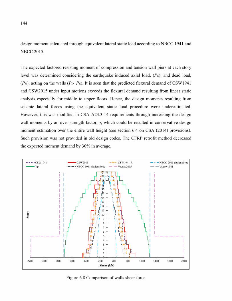
144
design moment calculated through equivalent lateral static load according to NBCC 1941 and
NBCC 2015.
The expected factored resisting moment of compression and tension wall piers at each story
level was determined considering the earthquake induced axial load, (PE), and dead load,
(PD), acting on the walls (PD±PE). It is seen that the predicted flexural demand of CSW1941
and CSW2015 under input motions exceeds the flexural demand resulting from linear static
analysis especially for middle to upper floors. Hence, the design moments resulting from
seismic lateral forces using the equivalent static load procedure were underestimated.
However, this was modified in CSA A23.3-14 requirements through increasing the design
wall moments by an over-strength factor, γ, which could be resulted in conservative design
moment estimation over the entire wall height (see section 6.4 on CSA (2014) provisions).
Such provision was not provided in old design codes. The CFRP retrofit method decreased
the expected moment demand by 30% in average.
Figure 6.8 Comparison of walls shear force
0123456789
1011121314151617181920
-2200 -1800 -1400 -1000 -600 -200 200 600 1000 1400 1800 2200
Stor
y
Shear (kN)
CSW1941 CSW2015 CSW1941-R NBCC 2015 design force
Vp NBCC 1941 design force Vr,csw2015 Vr,csw1941
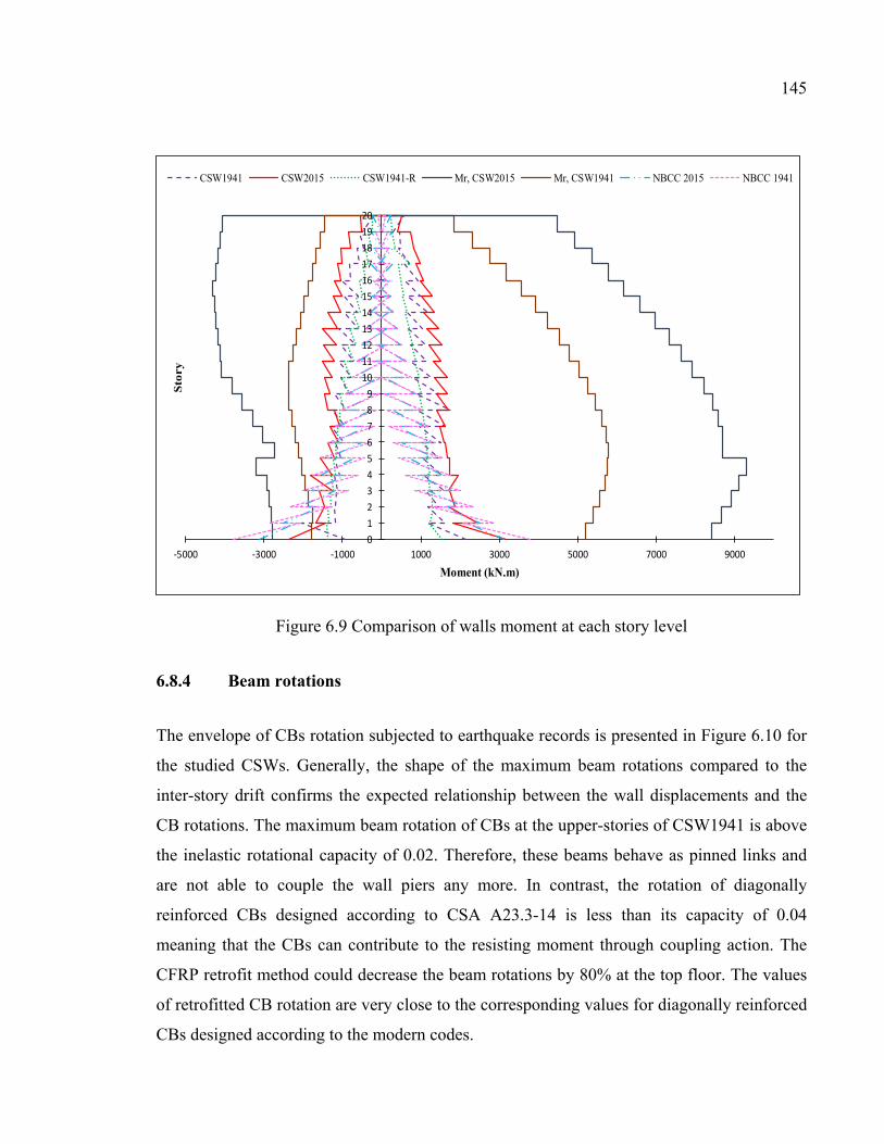
145
Figure 6.9 Comparison of walls moment at each story level
6.8.4 Beam rotations
The envelope of CBs rotation subjected to earthquake records is presented in Figure 6.10 for
the studied CSWs. Generally, the shape of the maximum beam rotations compared to the
inter-story drift confirms the expected relationship between the wall displacements and the
CB rotations. The maximum beam rotation of CBs at the upper-stories of CSW1941 is above
the inelastic rotational capacity of 0.02. Therefore, these beams behave as pinned links and
are not able to couple the wall piers any more. In contrast, the rotation of diagonally
reinforced CBs designed according to CSA A23.3-14 is less than its capacity of 0.04
meaning that the CBs can contribute to the resisting moment through coupling action. The
CFRP retrofit method could decrease the beam rotations by 80% at the top floor. The values
of retrofitted CB rotation are very close to the corresponding values for diagonally reinforced
CBs designed according to the modern codes.
0123456789
1011121314151617181920
-5000 -3000 -1000 1000 3000 5000 7000 9000
Sto
ry
Moment (kN.m)
CSW1941 CSW2015 CSW1941-R Mr, CSW2015 Mr, CSW1941 NBCC 2015 NBCC 1941
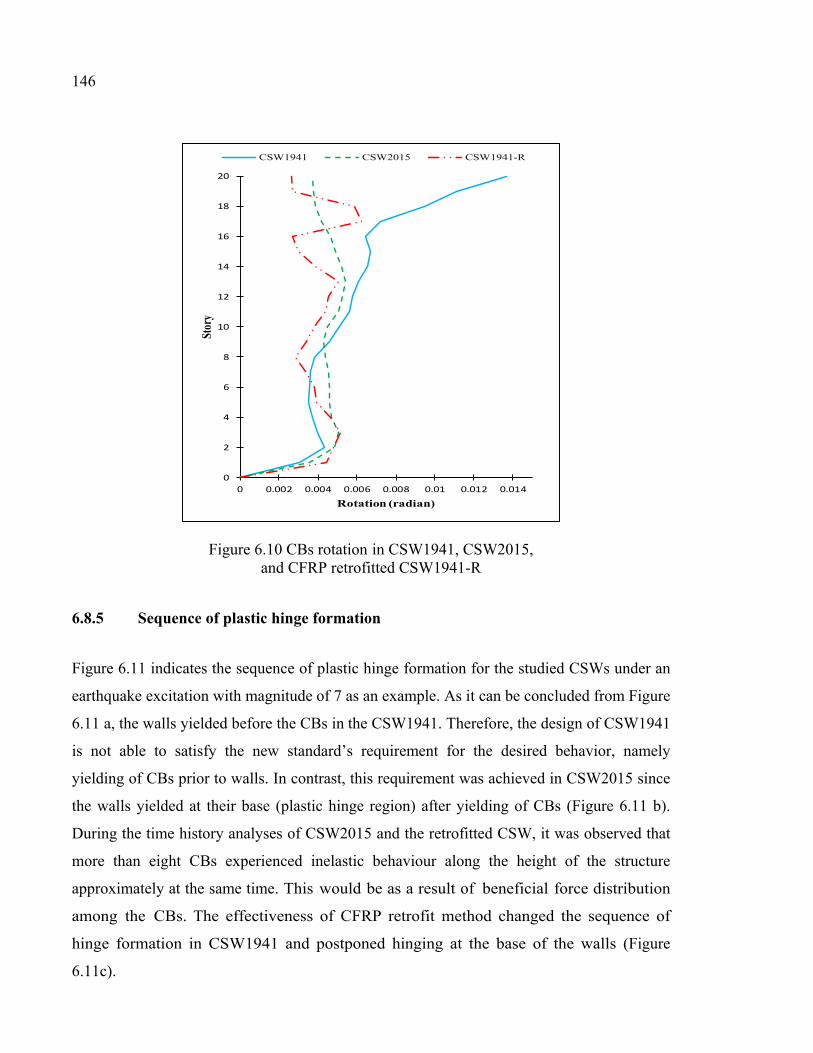
146
Figure 6.10 CBs rotation in CSW1941, CSW2015, and CFRP retrofitted CSW1941-R
6.8.5 Sequence of plastic hinge formation
Figure 6.11 indicates the sequence of plastic hinge formation for the studied CSWs under an
earthquake excitation with magnitude of 7 as an example. As it can be concluded from Figure
6.11 a, the walls yielded before the CBs in the CSW1941. Therefore, the design of CSW1941
is not able to satisfy the new standard’s requirement for the desired behavior, namely
yielding of CBs prior to walls. In contrast, this requirement was achieved in CSW2015 since
the walls yielded at their base (plastic hinge region) after yielding of CBs (Figure 6.11 b).
During the time history analyses of CSW2015 and the retrofitted CSW, it was observed that
more than eight CBs experienced inelastic behaviour along the height of the structure
approximately at the same time. This would be as a result of beneficial force distribution
among the CBs. The effectiveness of CFRP retrofit method changed the sequence of
hinge formation in CSW1941 and postponed hinging at the base of the walls (Figure
6.11c).
0
2
4
6
8
10
12
14
16
18
20
0 0.002 0.004 0.006 0.008 0.01 0.012 0.014
Stor
y
Rotation (radian)
CSW1941 CSW2015 CSW1941-R
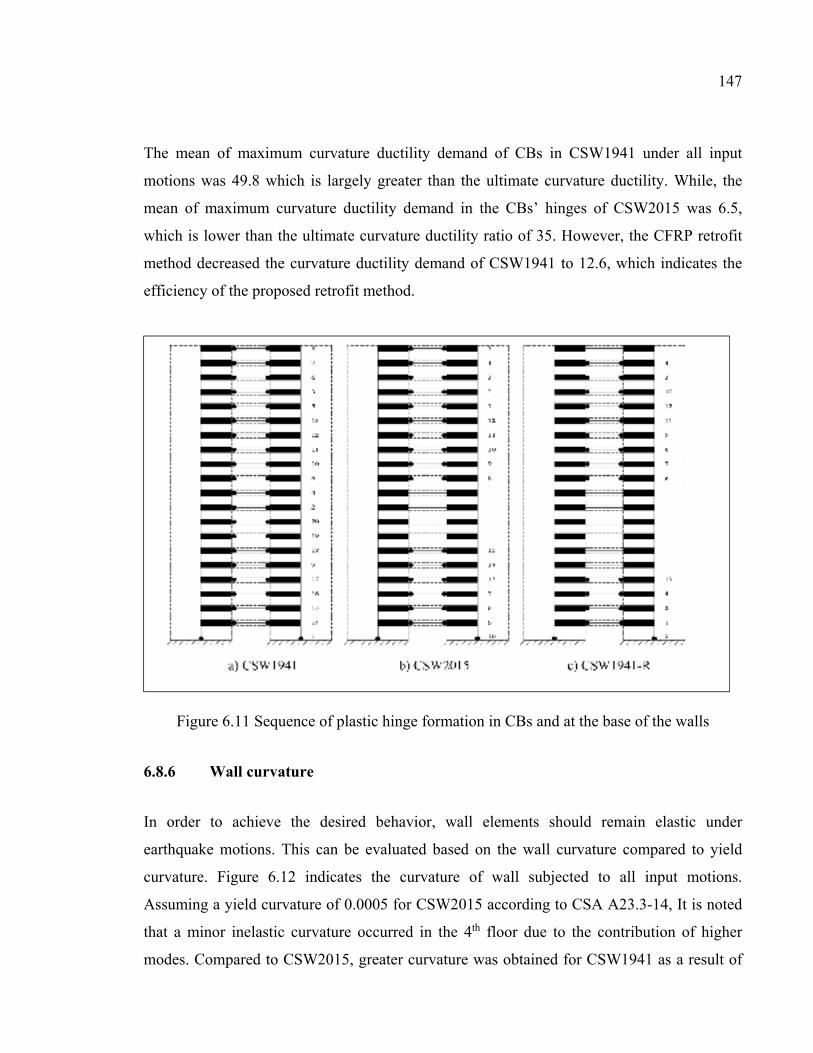
147
The mean of maximum curvature ductility demand of CBs in CSW1941 under all input
motions was 49.8 which is largely greater than the ultimate curvature ductility. While, the
mean of maximum curvature ductility demand in the CBs’ hinges of CSW2015 was 6.5,
which is lower than the ultimate curvature ductility ratio of 35. However, the CFRP retrofit
method decreased the curvature ductility demand of CSW1941 to 12.6, which indicates the
efficiency of the proposed retrofit method.
Figure 6.11 Sequence of plastic hinge formation in CBs and at the base of the walls
6.8.6 Wall curvature
In order to achieve the desired behavior, wall elements should remain elastic under
earthquake motions. This can be evaluated based on the wall curvature compared to yield
curvature. Figure 6.12 indicates the curvature of wall subjected to all input motions.
Assuming a yield curvature of 0.0005 for CSW2015 according to CSA A23.3-14, It is noted
that a minor inelastic curvature occurred in the 4th floor due to the contribution of higher
modes. Compared to CSW2015, greater curvature was obtained for CSW1941 as a result of
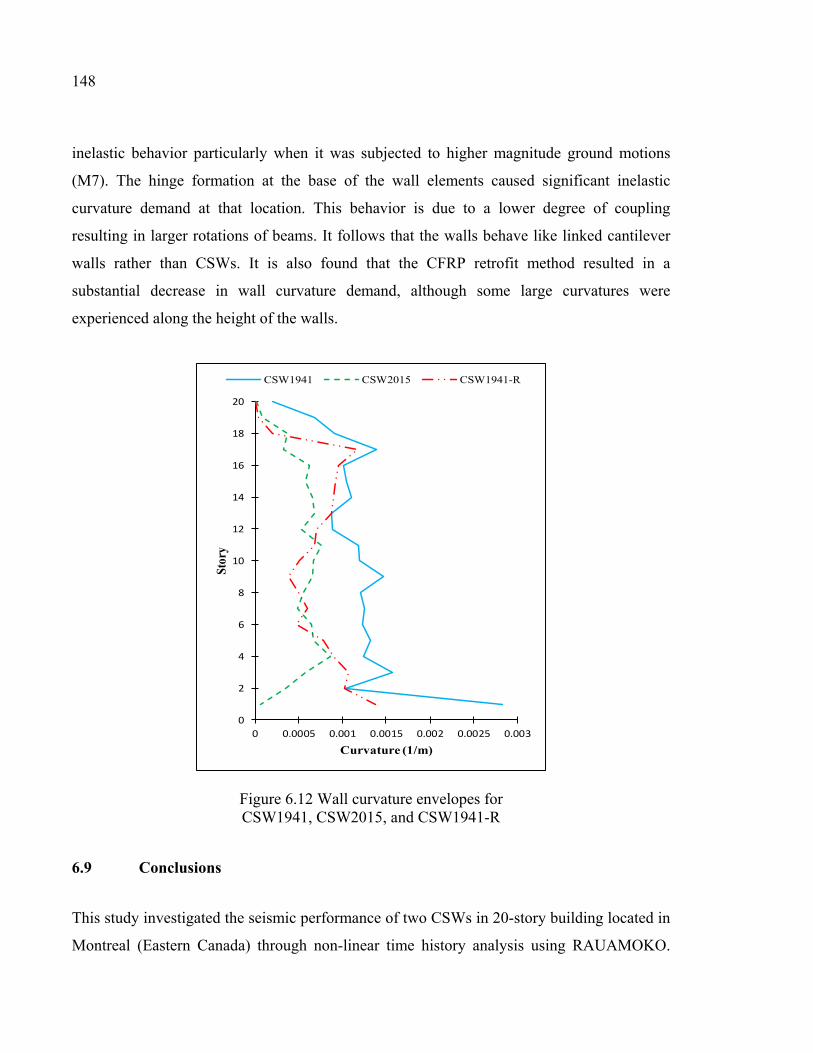
148
inelastic behavior particularly when it was subjected to higher magnitude ground motions
(M7). The hinge formation at the base of the wall elements caused significant inelastic
curvature demand at that location. This behavior is due to a lower degree of coupling
resulting in larger rotations of beams. It follows that the walls behave like linked cantilever
walls rather than CSWs. It is also found that the CFRP retrofit method resulted in a
substantial decrease in wall curvature demand, although some large curvatures were
experienced along the height of the walls.
Figure 6.12 Wall curvature envelopes for CSW1941, CSW2015, and CSW1941-R
6.9 Conclusions
This study investigated the seismic performance of two CSWs in 20-story building located in
Montreal (Eastern Canada) through non-linear time history analysis using RAUAMOKO.
0
2
4
6
8
10
12
14
16
18
20
0 0.0005 0.001 0.0015 0.002 0.0025 0.003
Stor
y
Curvature (1/m)
CSW1941 CSW2015 CSW1941-R
149
The first was designed according to NBCC 1941 (old code), with conventionally reinforced
CBs, while the second was designed according to CSA A23.3-14 and NBCC 2015 (modern
code) with diagonally reinforced CBs. An EB-CFRP retrofit method was implemented on
CSW 1941 to improve its seismic performance. The following conclusions obtained from the
non-linear analyses of CSW1941, CSW2015, and CSW1941 retrofitted with CFRP
(CSW1941-R) :
1) Unlike the NBCC 1941, the requirements prescribed by CSA A23.3-14 and NBCC 2015
for the capacity design of ductile coupled walls are acceptable in approximating design
demands. This can result in reliable seismic performance of newly designed CSWs.
2) The maximum inters-torey drift demand of CSW2015 was significantly less than that
prescribed by NBCC 2015, while, the inter-story drift demand experienced by CSW1941
was greater than the allowable limit.
3) The efficiency of CFRP retrofit method was evident since it considerably decreased the
inter-story drift to values very close to that of CSW2015.
4) The predicted wall shear forces at each story level in CSW2015 was less than the shear
design demand obtained from equivalent static base shear according to NBCC 2015. This
confirms the adequacy of NBCC 2015 in determination of the design shear force. In
contrast, the shear strength requirement of wall prescribed by the NBCC 1941
underestimated the design shear forces especially at the stories above wall mid-height.
5) The flexural demand of the wall’s storeys above mid-hight was significantly
underestimated by NBCC 1941. In contrast, distribution of equivalent static base shear as
lateral forces at each story level according to NBCC 2015 provide a better estimation of
flexural demands of wall’s stories.
6) A minor inelastic curvature was obtained in the walls of CSW2015 under earthquake
motions. In contrast, a greater curvature of wall segments was experienced in CSW1941.
In addition, a lower degree of coupling in CSW1941 resulted in greater rotation of CBs
well beyond the allowable inelastic rotational capacity.
7) The desired yielding sequence is not achieved in old-designed CSW1941 since the walls
yielded before the CBs. The sequence of yielding in CSW2015 indicated the proper level
of coupling as a large number of CBs yielded before the walls at the base.

150
8) Overal, CFRP retrofitting was an efficient method to enhance the seismic performance of
deficient old CSWs. In addition to improving the sequence of yielding in CBs and walls,
it effectively reduced story displacement, inter-story drift, CBs rotation, and ductility
demand.
CHAPTER 7
NON-LINEAR TIME HISTORY ANALYSIS OF COUPLED SHEAR WALLS: COMPARISON OF OLD DESIGN, MODERN DESIGN AND RETROFITTED WITH
EXTERNALLY BONDED CFRP COMPOSITES FOR WESTERN CANADA
Sara Honarparast a and Omar Chaallal b, F.ASCE
a, b Department of Construction Engineering, École de Technologie Supérieure, 1100 Notre-Dame West, Montreal, Quebec, Canada H3C 1K3
Paper submitted in Journal of Engineering Structures, September, 2018
7.1 Abstract
When appropriately designed, CSWs are very effective lateral load resisting systems for
medium to high rise buildings. They reduce the deformation demands on the building and
distribute the inelastic deformation between the CBs and the wall piers. Their seismic
performance depends mainly on the ability of their CBs to provide adequate stiffness and
strength. Therefore, the design of the CBs and the walls at their base is of paramount
importance. However, many existing buildings with CSWs feature unsatisfactory behaviour
under lateral loading as they were designed and constructed according to old codes and
standards with insufficient requirements for seismic design. Their seismic retrofit is therefore
inevitable. Many conventional retrofit techniques have been attempted in the past to improve
the seismic behavior of CSWs. Recently, an inovative techique using EB-FRP composite to
strengthen existing RC structural elements has emerged. The current study focuses on two
objectives related to CSWs: i) evaluate the seismic performance of old designed CSWs and
highlight their deficiencies by comparing its response with that of corresponding modern
design CSWs; and ii) evaluate the effectiveness of EB-CFRP retrofitting on the seismic
response of deficient CSWs. To achieve these objectives, two 20-story CSWs located in
Western seismic Canadian zone were considered. One CSW was designed according to old
NBCC 1941 and the other one designed in conformity with modern NBCC 2015 and CSA
A23.3-14. The nonlinear time-history analyses of the two types of CSWs as well as the
152
CFRP retrofitted one under simulated earthquake motions are carried out using
RUAUMOKO program. The observed results confirmed the effectiveness of CFRP
retrofitting in enhancing the seismic performance of deficient old CSWs.
7.2 Introduction
Reinforced concrete CSWs made of structural wall segments linked by CBs have proven to
be an efficient lateral load resisting system for medium to high rise buildings. When well
designed CSWs are capable of providing the strength and inelastic deformation capacity to
prevent collapse of a building during earthquakes. In comparison with single shear walls,
CSWs generally feature an enhanced seismic performance since they offer a higher lateral
stiffness and lower bending moments on each individual wall (El-Tawil et al., 2010). CSWs
resist lateral forces through the shear and moment resistance provided by the wall segments
but also through the action of the CBs which transmit shear forces from one wall to the other.
According to modern codes, it is required to design and detail the CBs with sufficient
strength, stiffness, and deformability. However, the wall segments must be stronger than the
CBs to allow an optimum performance of CSWs in dissipating earthquake energy in a ductile
manner. This is achieved through the formation of plastic hinges in most of the CBs prior to
plastic hinging at the base of each wall.
The structural behaviour of CSWs can be evaluated using the so-called degree of coupling
(DC), which is defined as the ratio of the overturning moment resisted by the push-pull
couple in the walls to the total structural overturning moment (see Equation 7.1). When
designing a ductile CSW, DC ≥ 0.66 is desirable, where:
cg
cg
PlMM
PlDC
++=
21
(7.1)
153
In the above equation, P is the magnitude of the tension or compression force resulting from
the coupling action; lcg is the lever arm between wall pier centroids and M1, M2 are the
moments resisted by wall pier 1 and 2.
Many existing buildings with CSWs as a lateral load resisting system were designed and
constructed according to old codes and standards, i.e., before the 1970’s. The design codes
and standards during the last decades have gone through major changes to improve safety
and seismic performance of structural elements. In view of the progress made in recent years
and the lack of seismic provisions in old design codes, CSWs designed to old codes are still
at risk of damage or collapse in probable moderate to strong earthquakes. This may be due to
numerous deficiencies that may be related to insufficient stiffness, inadequate flexural and
shear capacities, poor concrete confinement, failure to apply the strong walls-weak CBs
design philosophy. That allows the desired sequence of plastic hinge formation, inadequate
lap splices of the longitudinal reinforcement located at the plastic hinge region, and
insufficient embedment length of CB reinforcements into the walls.
During the past decades, a number of nonlinear analyses were carried out to investigate the
seismic performance of CSWs (Harries, 1995; McNeice, 2004; Boivin, 2006; Xuan, 2006;
Benazza, 2012). Harries (1995) studied the seismic behavior of four 18-story fully coupled
and partially CSW systems designed according to NBCC 1995 and located in Vancouver
(Western Canada). The CBs of the prototype structures included embedded steel CBs
designed according to CSA S16.1 M94 and RC CBs with conventional and with diagonal
reinforcement layouts designed according to CSA A23.3-M94. The results of non-linear
dynamic analyses of the structures indicated that CSWs with steel CBs to provide greater
energy dissipation, smaller lateral displacements, and enhanced ductility without significant
loss of strength or stiffness. Compared to RC CBs, Mc.Neice (2004) conducted an
investigation about the performance-based design method through non-linear dynamic
analyses for a 30-story coupled core wall structure designed according to the 2003
International Building Code (IBC, 2003) with reference to ASCE 7-02 (ASCE, 2002). Xuan
(2006) performed a nonlinear analysis of a 15-story coupled core wall with diagonally
154
reinforced CBs designed according to the provisions of NEHRP 2000, ACI 318-02, and
FEMA 356 to investigate the applicability and validity of the performance-based design
method. Boivin & Paultre (2010) also studied the seismic performance of a 12-story core
wall of an office building designed according to the NBCC 2005 and CSA 2004. Benazza
(2012) studied the seismic performance of 10, 20, and 30-story CSWs designed according to
NBCC 2010 and CSA A23.3-04.
It is noted that none of the above-mentioned studies has investigated the nonlinear seismic
response of existing CSWs designed and constructed before 1970s. In addition, given the
important evolution of modern seismic design codes and standards, the seismic retrofit of
existing RC CSWs designed to old codes is inevitable. Some retrofitting techniques dealing
with the strengthening of the existing CSWs were proposed to mitigate some of the
deficiencies (Harries, 1995; Chaallal & Nollet, 1997; Su & Zhu, 2005; Su & Cheng, 2011).
Alternative designs for CBs have also been proposed (Harries, 1995; Teng et al., 1999; Gong
& Shahrooz, 2001a; Lam et al., 2005; Motter et al., 2012). Although these techniques are
effective in enhancing the seismic response of structures, they may alter the distribution of
lateral loads on the building by adding more weight to the structure (Lombard et al., 2000).
The drawbacks of each of the proposed retrofit methods can be found in Honarparast &
Chaallal (2015).
In recent years, the use of EB-FRP has emerged as a viable, cost-effective and minimally
disruptive seismic retrofit for RC structural elements. FRP composites offer suitable
properties such as ease of application, high strength to weight ratio, and high resistance to
corrosion. The effectiveness of using EB-FRP retrofit method for shear and flexural
strengthening of individual shear walls was investigated in previous research studies
(Lombard et al., 2000; Antoniades et al., 2003; Paterson & Mitchell, 2003; Hiotakis, 2004;
Khalil & Ghobarah, 2005). The FRP composites have also been used in frames especially for
the beam-column joints (Liu, 2001; Quintana-Gallo, 2014; Hadi & Tran, 2016). The
efficiency of EB-FRP retrofit method to enhance the seismic behavior of CSWs was studied
in Arabzadeh & Galal (2017) through a nonlinear time history analysis of a 12-story C-
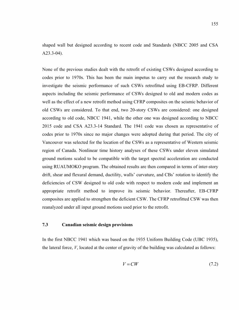
155
shaped wall but designed according to recent code and Standards (NBCC 2005 and CSA
A23.3-04).
None of the previous studies dealt with the retrofit of existing CSWs designed according to
codes prior to 1970s. This has been the main impetus to carry out the research study to
investigate the seismic performance of such CSWs retrofitted using EB-CFRP. Different
aspects including the seismic performance of CSWs designed to old and modern codes as
well as the effect of a new retrofit method using CFRP composites on the seismic behavior of
old CSWs are considered. To that end, two 20-story CSWs are considered: one designed
according to old code, NBCC 1941, while the other one was designed according to NBCC
2015 code and CSA A23.3-14 Standard. The 1941 code was chosen as representative of
codes prior to 1970s since no major changes were adopted during that period. The city of
Vancouver was selected for the location of the CSWs as a representative of Western seismic
region of Canada. Nonlinear time history analyses of these CSWs under eleven simulated
ground motions scaled to be compatible with the target spectral acceleration are conducted
using RUAUMOKO program. The obtained results are then compared in terms of inter-story
drift, shear and flexural demand, ductility, walls’ curvature, and CBs’ rotation to identify the
deficiencies of CSW designed to old code with respect to modern code and implement an
appropriate retrofit method to improve its seismic behavior. Thereafter, EB-CFRP
composites are applied to strengthen the deficient CSW. The CFRP retrofitted CSW was then
reanalyzed under all input ground motions used prior to the retrofit.
7.3 Canadian seismic design provisions
In the first NBCC 1941 which was based on the 1935 Uniform Building Code (UBC 1935),
the lateral force, V, located at the center of gravity of the building was calculated as follows:
CWV = (7.2)
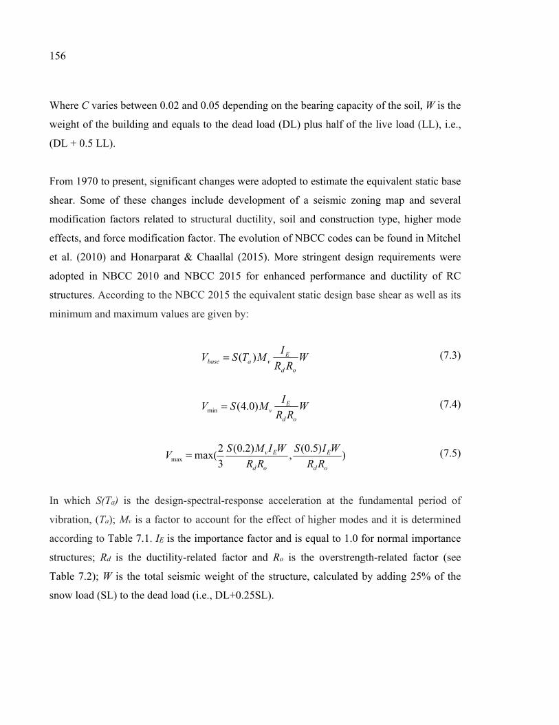
156
Where C varies between 0.02 and 0.05 depending on the bearing capacity of the soil, W is the
weight of the building and equals to the dead load (DL) plus half of the live load (LL), i.e.,
(DL + 0.5 LL).
From 1970 to present, significant changes were adopted to estimate the equivalent static base
shear. Some of these changes include development of a seismic zoning map and several
modification factors related to structural ductility, soil and construction type, higher mode
effects, and force modification factor. The evolution of NBCC codes can be found in Mitchel
et al. (2010) and Honarparat & Chaallal (2015). More stringent design requirements were
adopted in NBCC 2010 and NBCC 2015 for enhanced performance and ductility of RC
structures. According to the NBCC 2015 the equivalent static design base shear as well as its
minimum and maximum values are given by:
W
RR
IMTSV
od
Evabase )(= (7.3)
WRR
IMSV
od
Ev)0.4(min = (7.4)
))5.0(
,)2.0(
3
2max(max
od
E
od
Ev
RR
WIS
RR
WIMSV = (7.5)
In which S(Ta) is the design-spectral-response acceleration at the fundamental period of
vibration, (Ta); Mv is a factor to account for the effect of higher modes and it is determined
according to Table 7.1. IE is the importance factor and is equal to 1.0 for normal importance
structures; Rd is the ductility-related factor and Ro is the overstrength-related factor (see
Table 7.2); W is the total seismic weight of the structure, calculated by adding 25% of the
snow load (SL) to the dead load (i.e., DL+0.25SL).
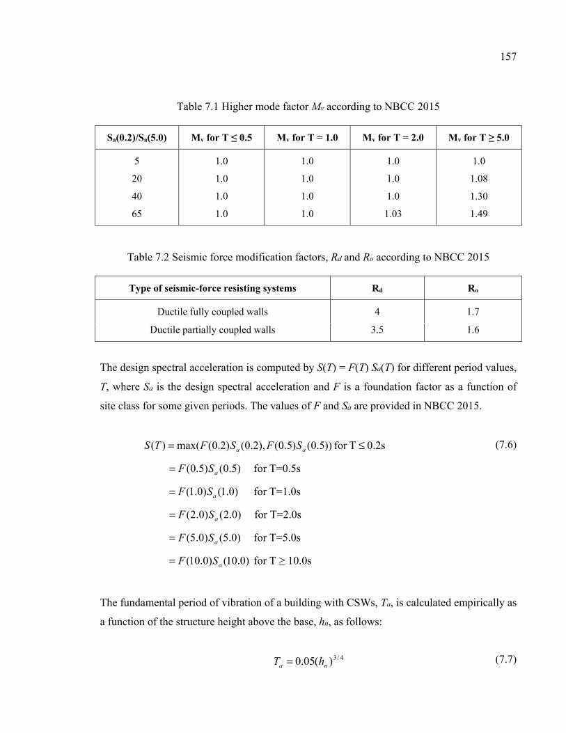
157
Table 7.1 Higher mode factor Mv according to NBCC 2015
Sa(0.2)/Sa(5.0) Mv for T ≤ 0.5 Mv for T = 1.0 Mv for T = 2.0 Mv for T ≥ 5.0
5
20
40
65
1.0
1.0
1.0
1.0
1.0
1.0
1.0
1.0
1.0
1.0
1.0
1.03
1.0
1.08
1.30
1.49
Table 7.2 Seismic force modification factors, Rd and Ro according to NBCC 2015
Type of seismic-force resisting systems Rd Ro
Ductile fully coupled walls 4 1.7
Ductile partially coupled walls 3.5 1.6
The design spectral acceleration is computed by S(T) = F(T) Sa(T) for different period values,
T, where Sa is the design spectral acceleration and F is a foundation factor as a function of
site class for some given periods. The values of F and Sa are provided in NBCC 2015.
0.2sTfor ))5.0()5.0(),2.0()2.0(max()( ≤= aa SFSFTS
)5.0()5.0( aSF= for T=0.5s
)0.1()0.1( aSF= for T=1.0s
)0.2()0.2( aSF= for T=2.0s
)0.5()0.5( aSF= for T=5.0s
)0.10()0.10( aSF= for T ≥ 10.0s
(7.6)
The fundamental period of vibration of a building with CSWs, Ta, is calculated empirically as
a function of the structure height above the base, hn, as follows:
4/3)(05.0 na hT = (7.7)
158
The base shear is distributed across the height of the structure considering a vibration shape
that is representative of the first mode of the structure. The lateral force at floor level i is
given by:
=
−= n
iii
iitbasei
hW
hWFVF
1
)( (7.8)
In Equation 7.8, Wi is the weight assigned to the ith story, and hi is the height of the ith story
above the base. In order to account for higher mode effects for structures with period greater
than 0.7sec, a portion of the base shear, Ft, is assigned to the top floor, where Ft is given by:
basebaseat VVTF 25.007.0 ≤= (7.9)
7.4 CSA standard A23.3-14 provisions for the design of CSWs
Prior to the first CSA standard published in 1959, there were some requirements in NBCC
code for the design of RC walls. However, there was no specific provisions for CSWs nor for
CBs. The first design requirements of CSWs were introduced in CSA A23.3-M84. Through
the evolution of seismic design codes in Canada, significant improvements were achieved in
the design and detailing requirements according to the CSA standards linked to seismic force
modification factors, Rd and Ro. In CSA A23.3-14 (CSA 2014), some seismic design
requirements were provided for shear and flexural strength design of ductile CSWs and
partially ductile CSWs.
To ensure ductility of coupled systems, the inelastic rotational capacity of both the walls and
the CBs shall be greater than their respective inelastic rotational demands. Thus, the inelastic
rotational demand on coupled walls and CBs are calculated using Equations 7.10 and 7.11,
respectively.
159
004.0≥
Δ=
w
dofid h
RRθ (7.10)
u
cg
w
dofid l
l
h
RR
Δ=θ (7.11)
Where ∆f is the deflection of the top of a wall due to the effect of factored loads and ∆f RoRd is
the design displacement; hw is the height of the wall, lcg is the horizontal distance between the
centroids of walls on either side of coupling beam, and lu is the length of the clear span.
The inelastic rotational capacity of CBs, θic, shall be taken as 0.04 and 0.02 for diagonally
reinforced and conventionally reinforced CBs, respectively. The maximum inelastic
rotational capacity should not be greater than 0.025 for wall elements.
According to CSA A23.3-14, the factored moment resistance of the walls shall exceed the
moment resulting from the nominal resistance of the CBs and the factored design moment in
the wall. Thus, to satisfy the capacity design requirement, the factored wall moments at each
level is increased by the wall over-strength factor, γ. The wall over-strength factor is the ratio
of the sum of the nominal shear capacities of the CBs, Vn, to the sum of the factored shear in
CBs due to lateral loading, Vf, and that is:
=
f
n
V
Vγ (7.12)
The detailing characteristics of the coupled walls dealing with walls and CBs geometry,
reinforcement layout in diagonal and conventional configuration, stirrups spacing, anchorage
length of CB reinforcements into the walls, and the amount of wall reinforcements in plastic
hinge region and out of it have been specified in CSA A23.3-14. New Canadian standards
provide provisions to design new CSWs and distinguish between two types (conventional or
diagonal configuration) of CBs depending on the shear stress level resulting from the
160
factored loads. CBs with conventional reinforcement are allowed by CSA A23.3-14 only if
the shear stress resulting from factored loads is less than cu fdl ′)/(1.0 , where lu is the clear
span, d the effective depth, and cf ′ the concrete compressive strength. However, prior to the
CSA A23.3-M84 (1984) standard, all CBs were designed and constructed with
conventionally reinforcement layout and the concept of diagonally reinforced CB was not yet
adopted in practice. While, for seismic loading most CBs fall into the diagonal reinforcement
category.
7.5 Description of studied building
In this study, a 20-story RC office building with CSW lateral load resisting system located in
Vancouver and founded on soil type C according to the NBCC 2015 was considered. The
plan of the building and elevation view of the CSWs are shown in Figure 7.1. The building
consists of a 20 m by 30 m floor plate of 200 mm thick slab, columns with section of
600×600 mm, and four CSWs in Axes A, B, E and F (Figure 7.1). The story floor-to-floor
heights are 3.5 m and hence the total height of the building is 70 m. Two CSWs were
designed and analyzed. The first, hereafter called CSW1941, was designed according to
NBCC 1941, and is representative of the old existing CSWs. The second one, hereafter called
CSW2015, was designed and detailed according to modern NBCC 2015 code and CSA
A23.3-14 Standard. The CSWs carry 100% of the lateral loads applied to the structure. The
walls and columns carry gravity loads based on their tributary areas. The structure is made of
normal-density concrete with a compressive strength of 25 MPa and 30 MPa respectively for
CSW1941 and CSW2015 and steel reinforcement with a yield strength of 400 MPa. The
walls have a cross section of 3 m × 0.35 m and are connected at the level of each floor by 700
mm deep and 350 mm wide CBs, i.e., a span to depth ratio of 2.86.
The computer program SAP 2000 (V19) was used for the initial elastic static analysis in
order to determine the design forces of the walls and CBs. The lateral forces resulting from
distribution of equivalent static base shear were applied at each story level. Then, based on
the obtained design values from analyses, the walls and CBs were designed and detailed
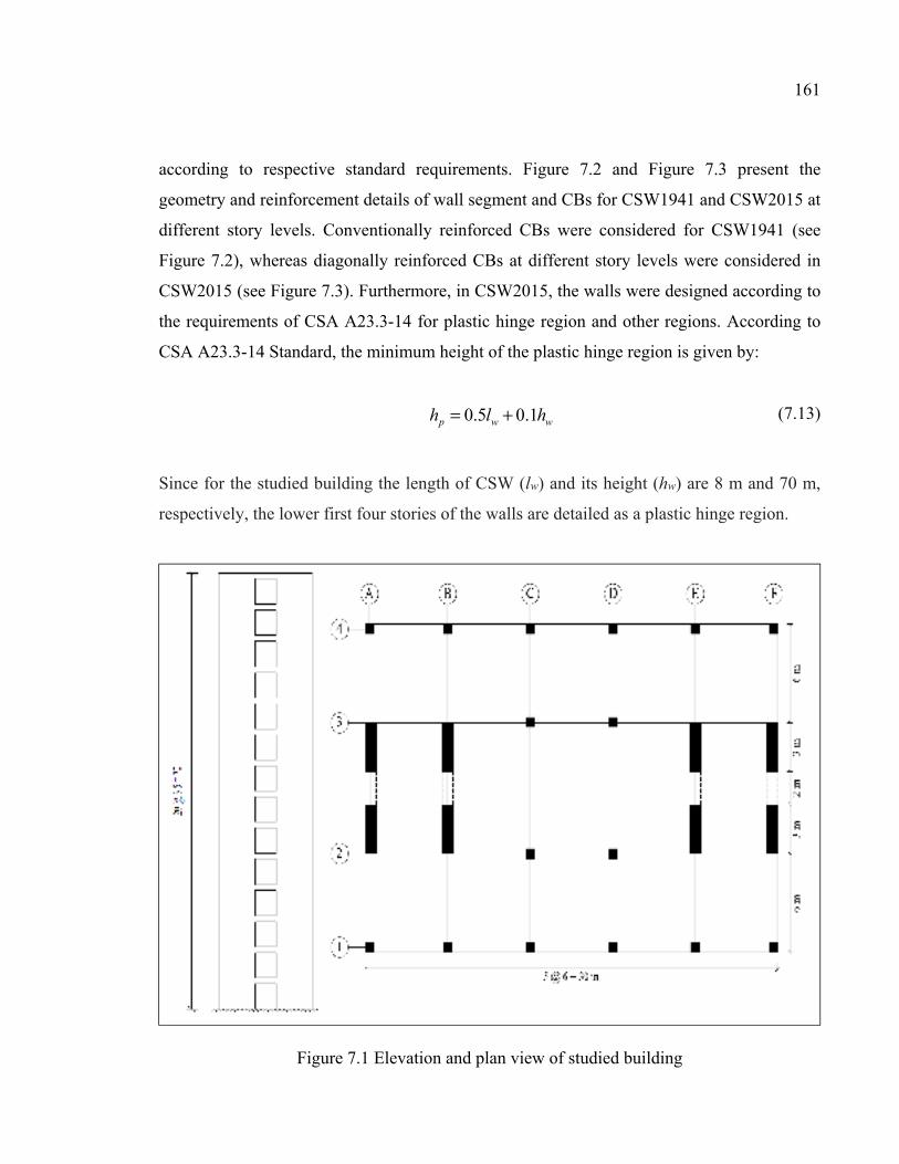
161
according to respective standard requirements. Figure 7.2 and Figure 7.3 present the
geometry and reinforcement details of wall segment and CBs for CSW1941 and CSW2015 at
different story levels. Conventionally reinforced CBs were considered for CSW1941 (see
Figure 7.2), whereas diagonally reinforced CBs at different story levels were considered in
CSW2015 (see Figure 7.3). Furthermore, in CSW2015, the walls were designed according to
the requirements of CSA A23.3-14 for plastic hinge region and other regions. According to
CSA A23.3-14 Standard, the minimum height of the plastic hinge region is given by:
wwp hlh 1.05.0 += (7.13)
Since for the studied building the length of CSW (lw) and its height (hw) are 8 m and 70 m,
respectively, the lower first four stories of the walls are detailed as a plastic hinge region.
Figure 7.1 Elevation and plan view of studied building
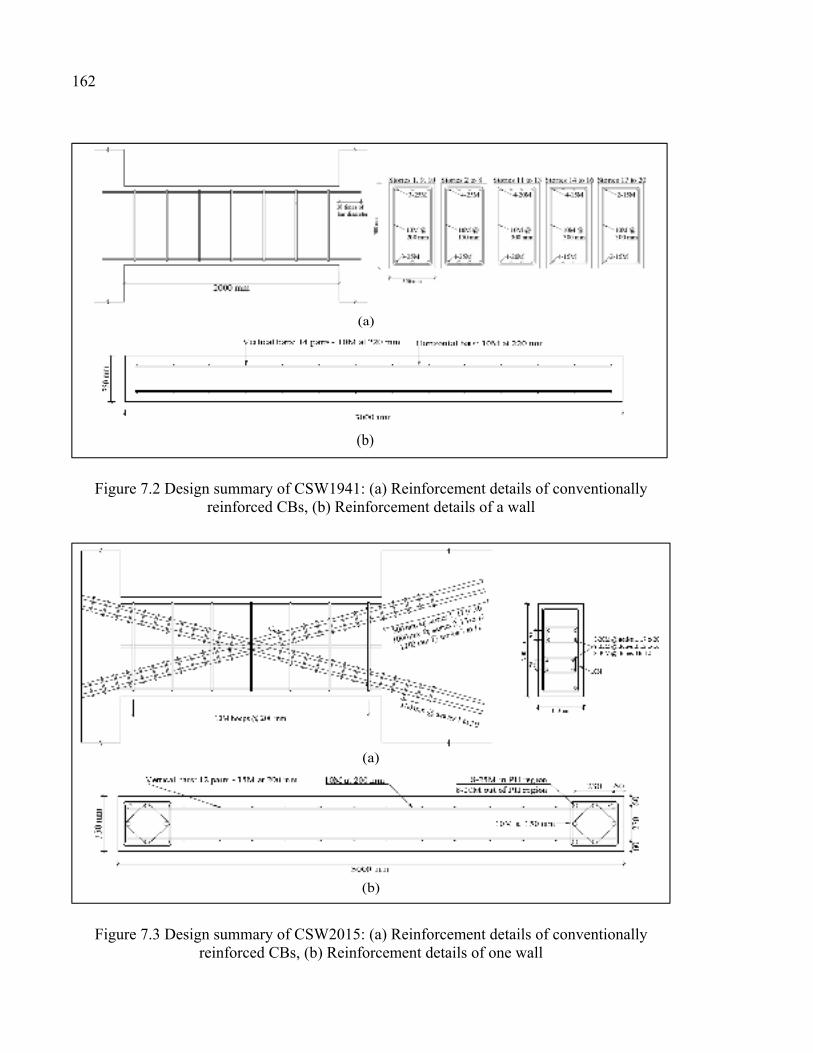
162
Figure 7.2 Design summary of CSW1941: (a) Reinforcement details of conventionally reinforced CBs, (b) Reinforcement details of a wall
Figure 7.3 Design summary of CSW2015: (a) Reinforcement details of conventionally reinforced CBs, (b) Reinforcement details of one wall
(a)
(b)
(a)
(b)
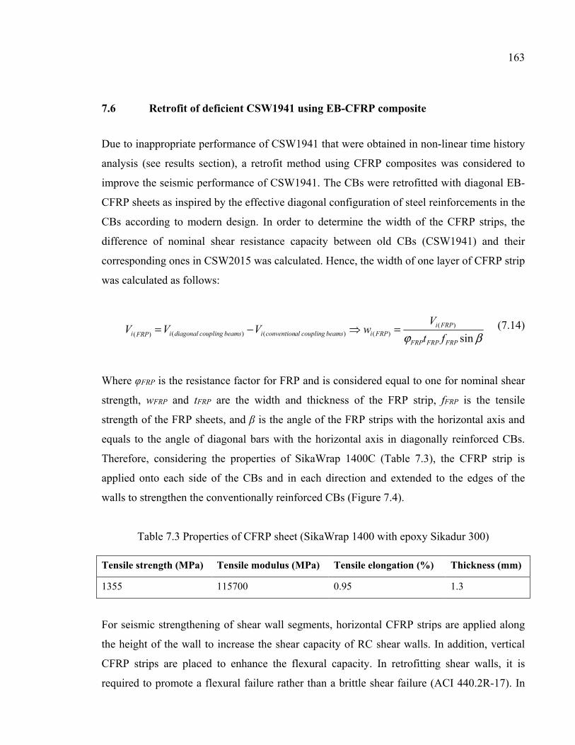
163
7.6 Retrofit of deficient CSW1941 using EB-CFRP composite
Due to inappropriate performance of CSW1941 that were obtained in non-linear time history
analysis (see results section), a retrofit method using CFRP composites was considered to
improve the seismic performance of CSW1941. The CBs were retrofitted with diagonal EB-
CFRP sheets as inspired by the effective diagonal configuration of steel reinforcements in the
CBs according to modern design. In order to determine the width of the CFRP strips, the
difference of nominal shear resistance capacity between old CBs (CSW1941) and their
corresponding ones in CSW2015 was calculated. Hence, the width of one layer of CFRP strip
was calculated as follows:
βϕ sin)(
)() () ()(FRPFRPFRP
FRPiFRPibeamscouplingalconventionibeamscouplingdiagonaliFRPi ft
VwVVV =−= (7.14)
Where φFRP is the resistance factor for FRP and is considered equal to one for nominal shear
strength, wFRP and tFRP are the width and thickness of the FRP strip, fFRP is the tensile
strength of the FRP sheets, and β is the angle of the FRP strips with the horizontal axis and
equals to the angle of diagonal bars with the horizontal axis in diagonally reinforced CBs.
Therefore, considering the properties of SikaWrap 1400C (Table 7.3), the CFRP strip is
applied onto each side of the CBs and in each direction and extended to the edges of the
walls to strengthen the conventionally reinforced CBs (Figure 7.4).
Table 7.3 Properties of CFRP sheet (SikaWrap 1400 with epoxy Sikadur 300) Tensile strength (MPa) Tensile modulus (MPa) Tensile elongation (%) Thickness (mm)
1355 115700 0.95 1.3
For seismic strengthening of shear wall segments, horizontal CFRP strips are applied along
the height of the wall to increase the shear capacity of RC shear walls. In addition, vertical
CFRP strips are placed to enhance the flexural capacity. In retrofitting shear walls, it is
required to promote a flexural failure rather than a brittle shear failure (ACI 440.2R-17). In
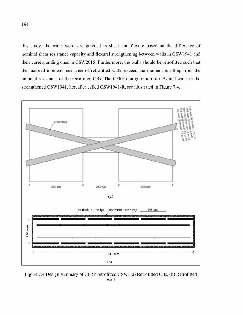
164
this study, the walls were strengthened in shear and flexure based on the difference of
nominal shear resistance capacity and flexural strengthening between walls in CSW1941 and
their corresponding ones in CSW2015. Furthermore, the walls should be retrofitted such that
the factored moment resistance of retrofitted walls exceed the moment resulting from the
nominal resistance of the retrofitted CBs. The CFRP configuration of CBs and walls in the
strengthened CSW1941, hereafter called CSW1941-R, are illustrated in Figure 7.4.
Figure 7.4 Design summary of CFRP retrofitted CSW: (a) Retrofitted CBs, (b) Retrofitted wall
(b)
(a)
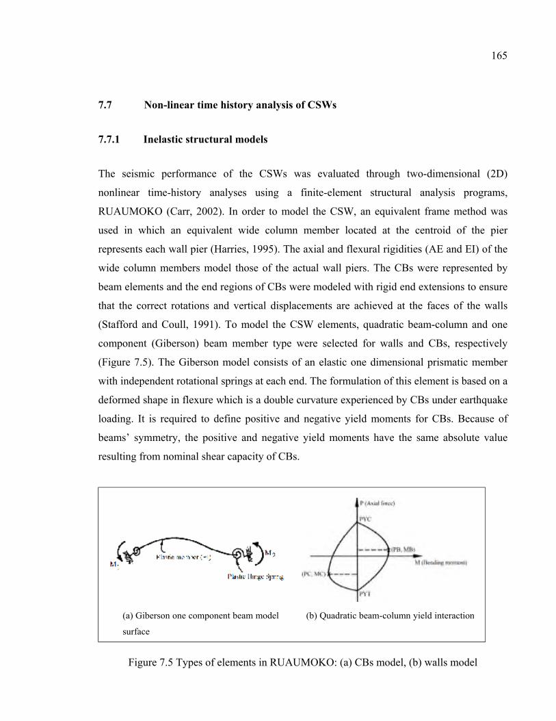
165
7.7 Non-linear time history analysis of CSWs
7.7.1 Inelastic structural models
The seismic performance of the CSWs was evaluated through two-dimensional (2D)
nonlinear time-history analyses using a finite-element structural analysis programs,
RUAUMOKO (Carr, 2002). In order to model the CSW, an equivalent frame method was
used in which an equivalent wide column member located at the centroid of the pier
represents each wall pier (Harries, 1995). The axial and flexural rigidities (AE and EI) of the
wide column members model those of the actual wall piers. The CBs were represented by
beam elements and the end regions of CBs were modeled with rigid end extensions to ensure
that the correct rotations and vertical displacements are achieved at the faces of the walls
(Stafford and Coull, 1991). To model the CSW elements, quadratic beam-column and one
component (Giberson) beam member type were selected for walls and CBs, respectively
(Figure 7.5). The Giberson model consists of an elastic one dimensional prismatic member
with independent rotational springs at each end. The formulation of this element is based on a
deformed shape in flexure which is a double curvature experienced by CBs under earthquake
loading. It is required to define positive and negative yield moments for CBs. Because of
beams’ symmetry, the positive and negative yield moments have the same absolute value
resulting from nominal shear capacity of CBs.
Figure 7.5 Types of elements in RUAUMOKO: (a) CBs model, (b) walls model
(a) Giberson one component beam model (b) Quadratic beam-column yield interaction
surface
166
In order to model the walls through quadratic beam-column element, the axial load-moment
interaction surface of walls in plastic hinge region and other regions is required. Therefore,
the non-linear section analysis program Xtract (Imbsen, 2004) was used to determine the
axial load-moment interaction surface of the walls section. In this program, the section
geometry, reinforcement details, and non-linear material models should be specified. The
stress–strain model of Mander et al. (1988) was utilized for unconfined and steel-confined
concrete and elasto-plastic model with strain hardening was considered for steel
reinforcement behavior. The steel-confined concrete model incorporates the effects of the
increased compressive strain capacity in addition to an increased compressive strength due to
passive confinement from transverse reinforcing steel. However, this model is not
appropriate for FRP-confined concrete because of the linear elastic behavior of FRP
composites up to rupture. In FRP-confined concrete the lateral confining pressure increases
continuously with the applied load. Therefore, the FRP-confined concrete model proposed by
Lam & Teng (2003) was used to model the material behavior of retrofitted members.
A main issue in nonlinear analysis of structures in RUAUMOKO is selecting convenient
hysteretic rule to simulate the inelastic behavior of structural members. In this study,
hysteresis curves were assigned to CBs and walls considering previous studies (McNiece,
2004; Boivin, 2006; Benazza, 2012) as well as results of some experimental tests conducted
by the authors. A Q-HYST degrading stiffness hysteretic behavior (Saiidi & Sozen, 1979)
was adopted for wall elements. Q- HYST is a simple model taking into account stiffness
reduction during unloading from a point beyond the yield point of primary curve besides
stiffness reduction at the load reversal stage. The hysteresis behavior of old designed
conventionally reinforced CBs was simulated by Takeda with slip degrading stiffness model
(Otani, 1980; Kabeyasawa et al., 1983). This model allows for the pinching action in the
hysteresis behavior caused by slippage of the CB's main longitudinal reinforcement. It also
incorporates the strength decay beyond the yielding moment. A modified bilinear Takeda
hysteresis curve (Otani, 1974) was selected for both diagonally reinforced and CFRP
retrofitted CBs. The primary curve of modified Takeda model is taken as an elastic-perfectly
plastic response. The yield bending moment of this response equals to the yield resisting
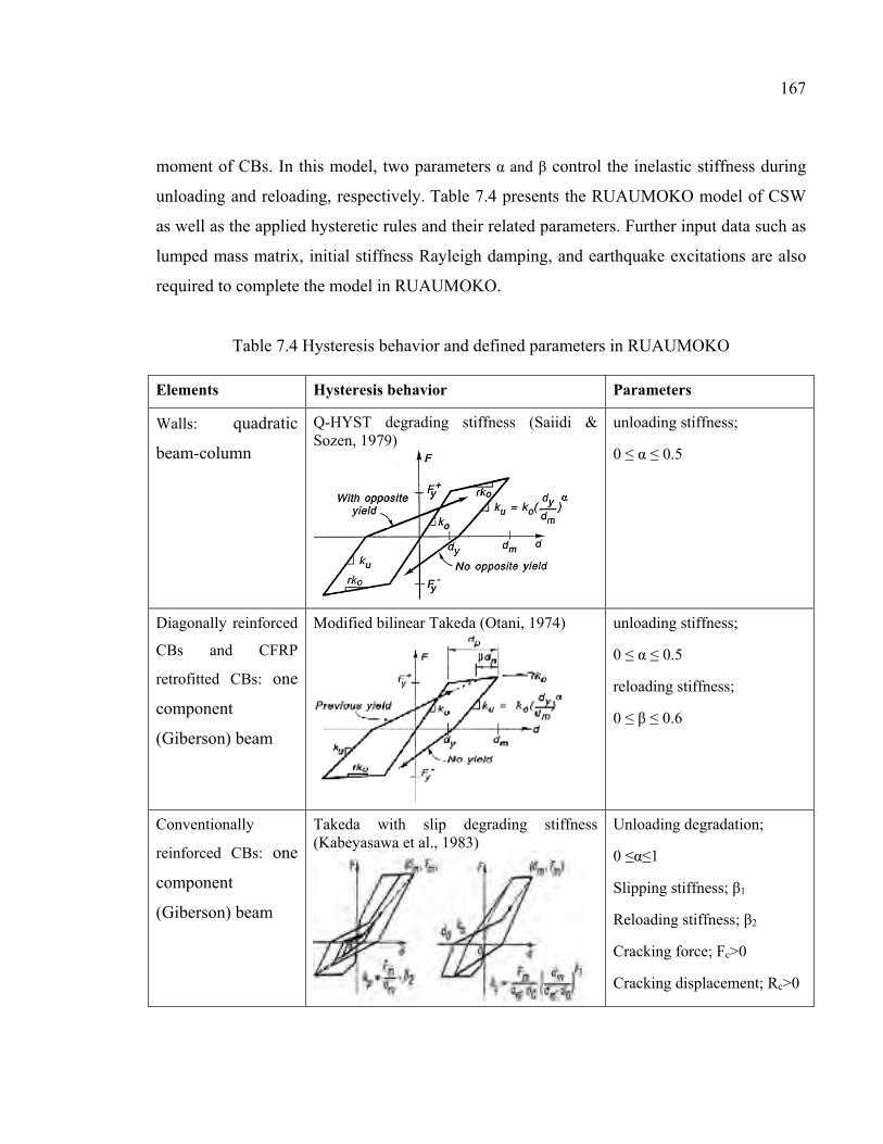
167
moment of CBs. In this model, two parameters α and β control the inelastic stiffness during
unloading and reloading, respectively. Table 7.4 presents the RUAUMOKO model of CSW
as well as the applied hysteretic rules and their related parameters. Further input data such as
lumped mass matrix, initial stiffness Rayleigh damping, and earthquake excitations are also
required to complete the model in RUAUMOKO.
Table 7.4 Hysteresis behavior and defined parameters in RUAUMOKO Elements Hysteresis behavior Parameters
Walls: quadratic
beam-column
Q-HYST degrading stiffness (Saiidi & Sozen, 1979)
unloading stiffness;
0 ≤ α ≤ 0.5
Diagonally reinforced
CBs and CFRP
retrofitted CBs: one
component
(Giberson) beam
Modified bilinear Takeda (Otani, 1974)
unloading stiffness;
0 ≤ α ≤ 0.5
reloading stiffness;
0 ≤ β ≤ 0.6
Conventionally
reinforced CBs: one
component
(Giberson) beam
Takeda with slip degrading stiffness (Kabeyasawa et al., 1983)
Unloading degradation;
0 ≤α≤1
Slipping stiffness; β1
Reloading stiffness; β2
Cracking force; Fc>0
Cracking displacement; Rc>0
168
7.7.2 Selecting and scaling of earthquake ground motion histories
Due to lack of recorded ground motions from earthquake events, simulated time-histories for
site class C were selected from the Engineering Seismology Toolbox website
(www.seismotoolbox.ca) (Atkinson, 2009). The earthquake records were selected and scaled
according to the latest method proposed by Tremblay et al. (2015). In this technique, in the
first step a period range (TR) and a target spectrum ST(T) are determined. As defined in
Equation 7.15, the lower and upper limit of TR is computed considering the fundamental
period of the structure (T) and the period of the highest vibration mode required to cumulate
a minimum participating mass of 90% of the structure mass (T90%) as follows:
]5.1 ,0.2max[ ]; ,2.0min[ max%90min sTTTTT == (7.15)
The target spectrum is defined for the location and soil type according to NBCC 2015. Figure
7.6 illustrates the target spectrum for soil type C in Vancouver.
In the second step, appropriate ground motions should be selected from the accelerograms
developed by Atkinson (2009). There are four sets of 45 simulated earthquake time-histories
with magnitude of 6 and 7 for Western Canada. As shown in Table 7.5, two scenarios
including five ground motions with magnitude of 6 (M6) and six ground motions of M7 were
considered. In order to select the proper earthquake records compatible with target spectral,
the mean and standard deviation are calculated for the ratio of target spectral amplitude
(ST(T)) to the ground motions spectral amplitude (Sg(T)) over the corresponding scenario
period. Then, the records with lowest standard deviation and a mean between 0.5 and 2.0 are
selected. The mean value of ST(T)/Sg(T) ratio of each selected ground motion is its scale
factor (SF1). In the final step, the selected ground motions are multiplied by their
corresponding scaling factor. After that, the mean response spectra of each suite of scaled
earthquakes are computed within each scenario-specific period range. If it falls more than
10% below the ST(T), a second scale factor (SF2) is calculated so that the difference between
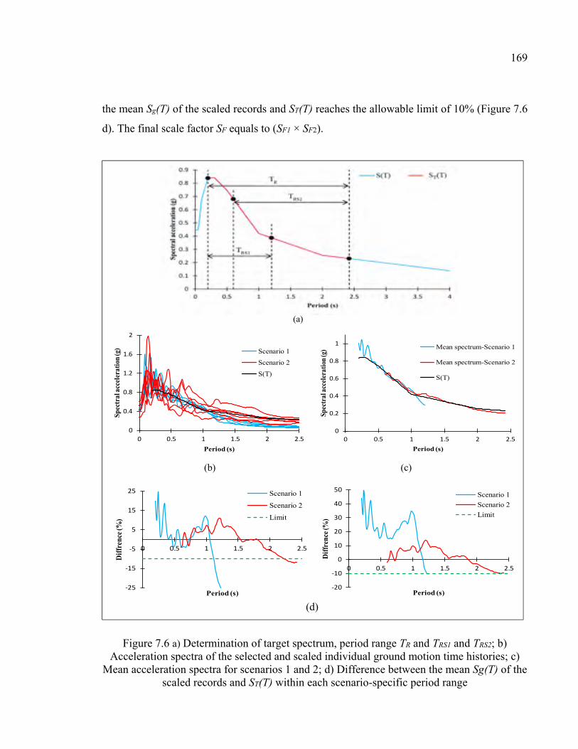
169
the mean Sg(T) of the scaled records and ST(T) reaches the allowable limit of 10% (Figure 7.6
d). The final scale factor SF equals to (SF1 × SF2).
Figure 7.6 a) Determination of target spectrum, period range TR and TRS1 and TRS2; b) Acceleration spectra of the selected and scaled individual ground motion time histories; c)
Mean acceleration spectra for scenarios 1 and 2; d) Difference between the mean Sg(T) of the scaled records and ST(T) within each scenario-specific period range
(a)
0
0.4
0.8
1.2
1.6
2
0 0.5 1 1.5 2 2.5
Spec
tral
acc
eler
atio
n (g
)
Period (s)
Scenario 1
Scenario 2
S(T)
0
0.2
0.4
0.6
0.8
1
0 0.5 1 1.5 2 2.5
Spec
tral
acc
eler
atio
n (g
)
Period (s)
Mean spectrum-Scenario 1
Mean spectrum-Scenario 2
S(T)
-25
-15
-5
5
15
25
0 0.5 1 1.5 2 2.5
Dif
fren
ce (%
)
Period (s)
Scenario 1
Scenario 2
Limit
(b) (c)
(d)
-20
-10
0
10
20
30
40
50
0 0.5 1 1.5 2 2.5
Dif
fren
ce (%
)
Period (s)
Scenario 1
Scenario 2
Limit
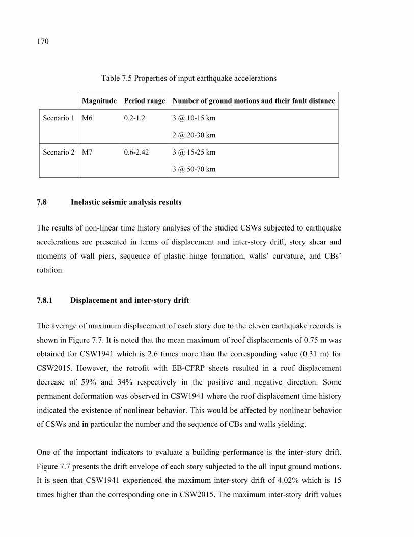
170
Table 7.5 Properties of input earthquake accelerations
Magnitude Period range Number of ground motions and their fault distance
Scenario 1 M6 0.2-1.2 3 @ 10-15 km
2 @ 20-30 km
Scenario 2 M7 0.6-2.42 3 @ 15-25 km
3 @ 50-70 km
7.8 Inelastic seismic analysis results
The results of non-linear time history analyses of the studied CSWs subjected to earthquake
accelerations are presented in terms of displacement and inter-story drift, story shear and
moments of wall piers, sequence of plastic hinge formation, walls’ curvature, and CBs’
rotation.
7.8.1 Displacement and inter-story drift
The average of maximum displacement of each story due to the eleven earthquake records is
shown in Figure 7.7. It is noted that the mean maximum of roof displacements of 0.75 m was
obtained for CSW1941 which is 2.6 times more than the corresponding value (0.31 m) for
CSW2015. However, the retrofit with EB-CFRP sheets resulted in a roof displacement
decrease of 59% and 34% respectively in the positive and negative direction. Some
permanent deformation was observed in CSW1941 where the roof displacement time history
indicated the existence of nonlinear behavior. This would be affected by nonlinear behavior
of CSWs and in particular the number and the sequence of CBs and walls yielding.
One of the important indicators to evaluate a building performance is the inter-story drift.
Figure 7.7 presents the drift envelope of each story subjected to the all input ground motions.
It is seen that CSW1941 experienced the maximum inter-story drift of 4.02% which is 15
times higher than the corresponding one in CSW2015. The maximum inter-story drift values
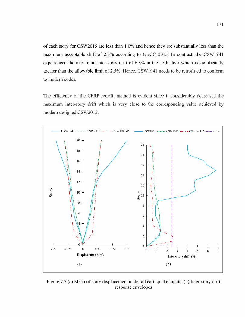
171
of each story for CSW2015 are less than 1.0% and hence they are substantially less than the
maximum acceptable drift of 2.5% according to NBCC 2015. In contrast, the CSW1941
experienced the maximum inter-story drift of 6.8% in the 15th floor which is significantly
greater than the allowable limit of 2.5%. Hence, CSW1941 needs to be retrofitted to conform
to modern codes.
The efficiency of the CFRP retrofit method is evident since it considerably decreased the
maximum inter-story drift which is very close to the corresponding value achieved by
modern designed CSW2015.
Figure 7.7 (a) Mean of story displacement under all earthquake inputs; (b) Inter-story drift response envelopes
0
2
4
6
8
10
12
14
16
18
20
-0.5 -0.25 0 0.25 0.5 0.75
Sto
ry
Displacement (m)
CSW1941 CSW2015 CSW1941-R
0
2
4
6
8
10
12
14
16
18
20
0 1 2 3 4 5 6 7
Sto
ry
Inter-story drfit (%)
CSW1941 CSW2015 CSW1941-R Limit
(a) (b)
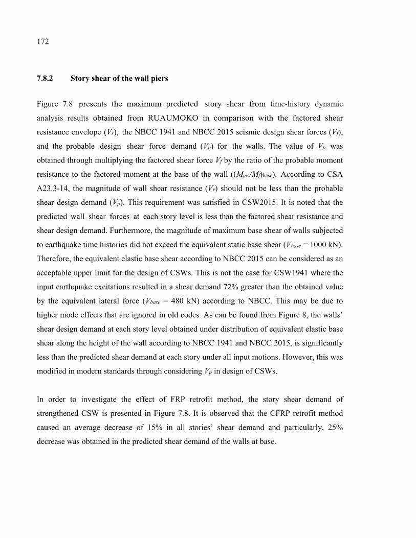
172
7.8.2 Story shear of the wall piers
Figure 7.8 presents the maximum predicted story shear from time-history dynamic
analysis results obtained from RUAUMOKO in comparison with the factored shear
resistance envelope (Vr), the NBCC 1941 and NBCC 2015 seismic design shear forces (Vf),
and the probable design shear force demand (Vp) for the walls. The value of Vp was
obtained through multiplying the factored shear force Vf by the ratio of the probable moment
resistance to the factored moment at the base of the wall ((Mpw/Mf)base). According to CSA
A23.3-14, the magnitude of wall shear resistance (Vr) should not be less than the probable
shear design demand (Vp). This requirement was satisfied in CSW2015. It is noted that the
predicted wall shear forces at each story level is less than the factored shear resistance and
shear design demand. Furthermore, the magnitude of maximum base shear of walls subjected
to earthquake time histories did not exceed the equivalent static base shear (Vbase = 1000 kN).
Therefore, the equivalent elastic base shear according to NBCC 2015 can be considered as an
acceptable upper limit for the design of CSWs. This is not the case for CSW1941 where the
input earthquake excitations resulted in a shear demand 72% greater than the obtained value
by the equivalent lateral force (Vbase = 480 kN) according to NBCC. This may be due to
higher mode effects that are ignored in old codes. As can be found from Figure 8, the walls’
shear design demand at each story level obtained under distribution of equivalent elastic base
shear along the height of the wall according to NBCC 1941 and NBCC 2015, is significantly
less than the predicted shear demand at each story under all input motions. However, this was
modified in modern standards through considering Vp in design of CSWs.
In order to investigate the effect of FRP retrofit method, the story shear demand of
strengthened CSW is presented in Figure 7.8. It is observed that the CFRP retrofit method
caused an average decrease of 15% in all stories’ shear demand and particularly, 25%
decrease was obtained in the predicted shear demand of the walls at base.
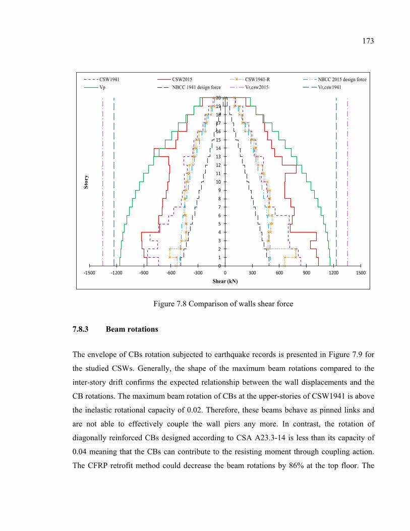
173
Figure 7.8 Comparison of walls shear force
7.8.3 Beam rotations
The envelope of CBs rotation subjected to earthquake records is presented in Figure 7.9 for
the studied CSWs. Generally, the shape of the maximum beam rotations compared to the
inter-story drift confirms the expected relationship between the wall displacements and the
CB rotations. The maximum beam rotation of CBs at the upper-stories of CSW1941 is above
the inelastic rotational capacity of 0.02. Therefore, these beams behave as pinned links and
are not able to effectively couple the wall piers any more. In contrast, the rotation of
diagonally reinforced CBs designed according to CSA A23.3-14 is less than its capacity of
0.04 meaning that the CBs can contribute to the resisting moment through coupling action.
The CFRP retrofit method could decrease the beam rotations by 86% at the top floor. The
0123456789
1011121314151617181920
-1500 -1200 -900 -600 -300 0 300 600 900 1200 1500
Sto
ry
Shear (kN)
CSW1941 CSW2015 CSW1941-R NBCC 2015 design force
Vp NBCC 1941 design force Vr,csw2015 Vr,csw1941
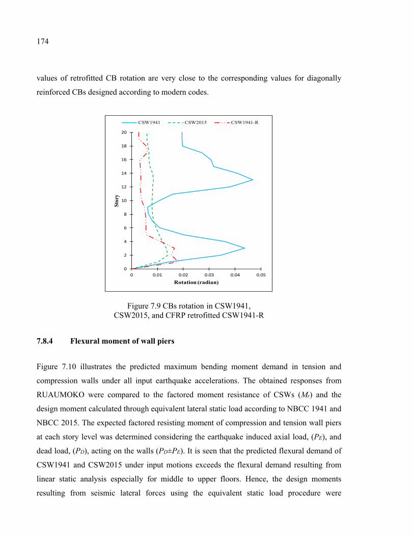
174
values of retrofitted CB rotation are very close to the corresponding values for diagonally
reinforced CBs designed according to modern codes.
Figure 7.9 CBs rotation in CSW1941, CSW2015, and CFRP retrofitted CSW1941-R
7.8.4 Flexural moment of wall piers
Figure 7.10 illustrates the predicted maximum bending moment demand in tension and
compression walls under all input earthquake accelerations. The obtained responses from
RUAUMOKO were compared to the factored moment resistance of CSWs (Mr) and the
design moment calculated through equivalent lateral static load according to NBCC 1941 and
NBCC 2015. The expected factored resisting moment of compression and tension wall piers
at each story level was determined considering the earthquake induced axial load, (PE), and
dead load, (PD), acting on the walls (PD±PE). It is seen that the predicted flexural demand of
CSW1941 and CSW2015 under input motions exceeds the flexural demand resulting from
linear static analysis especially for middle to upper floors. Hence, the design moments
resulting from seismic lateral forces using the equivalent static load procedure were
0
2
4
6
8
10
12
14
16
18
20
0 0.01 0.02 0.03 0.04 0.05
Stor
y
Rotation (radian)
CSW1941 CSW2015 CSW1941-R
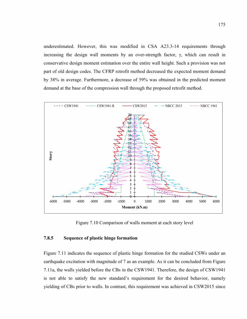
175
underestimated. However, this was modified in CSA A23.3-14 requirements through
increasing the design wall moments by an over-strength factor, γ, which can result in
conservative design moment estimation over the entire wall height. Such a provision was not
part of old design codes. The CFRP retrofit method decreased the expected moment demand
by 38% in average. Furthermore, a decrease of 59% was obtained in the predicted moment
demand at the base of the compression wall through the proposed retrofit method.
Figure 7.10 Comparison of walls moment at each story level
7.8.5 Sequence of plastic hinge formation
Figure 7.11 indicates the sequence of plastic hinge formation for the studied CSWs under an
earthquake excitation with magnitude of 7 as an example. As it can be concluded from Figure
7.11a, the walls yielded before the CBs in the CSW1941. Therefore, the design of CSW1941
is not able to satisfy the new standard’s requirement for the desired behavior, namely
yielding of CBs prior to walls. In contrast, this requirement was achieved in CSW2015 since
0123456789
1011121314151617181920
-6000 -5000 -4000 -3000 -2000 -1000 0 1000 2000 3000 4000 5000 6000
Sto
ry
Moment (kN.m)
CSW1941 CSW1941-R CSW2015 NBCC 2015 NBCC 1941
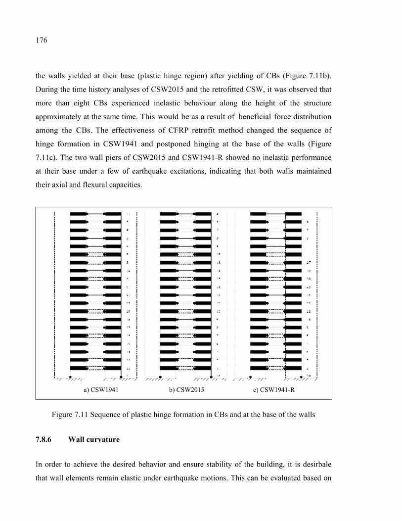
176
the walls yielded at their base (plastic hinge region) after yielding of CBs (Figure 7.11b).
During the time history analyses of CSW2015 and the retrofitted CSW, it was observed that
more than eight CBs experienced inelastic behaviour along the height of the structure
approximately at the same time. This would be as a result of beneficial force distribution
among the CBs. The effectiveness of CFRP retrofit method changed the sequence of
hinge formation in CSW1941 and postponed hinging at the base of the walls (Figure
7.11c). The two wall piers of CSW2015 and CSW1941-R showed no inelastic performance
at their base under a few of earthquake excitations, indicating that both walls maintained
their axial and flexural capacities.
Figure 7.11 Sequence of plastic hinge formation in CBs and at the base of the walls
7.8.6 Wall curvature
In order to achieve the desired behavior and ensure stability of the building, it is desirbale
that wall elements remain elastic under earthquake motions. This can be evaluated based on
a) CSW1941 b) CSW2015 c) CSW1941-R
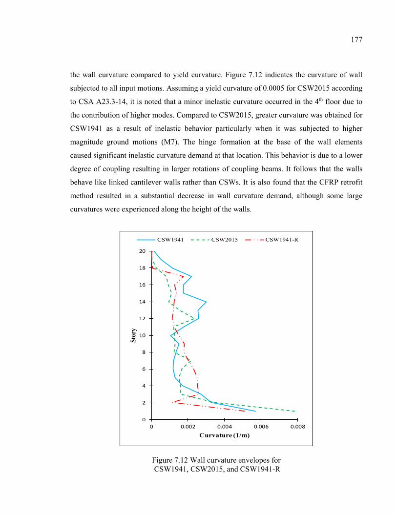
177
the wall curvature compared to yield curvature. Figure 7.12 indicates the curvature of wall
subjected to all input motions. Assuming a yield curvature of 0.0005 for CSW2015 according
to CSA A23.3-14, it is noted that a minor inelastic curvature occurred in the 4th floor due to
the contribution of higher modes. Compared to CSW2015, greater curvature was obtained for
CSW1941 as a result of inelastic behavior particularly when it was subjected to higher
magnitude ground motions (M7). The hinge formation at the base of the wall elements
caused significant inelastic curvature demand at that location. This behavior is due to a lower
degree of coupling resulting in larger rotations of coupling beams. It follows that the walls
behave like linked cantilever walls rather than CSWs. It is also found that the CFRP retrofit
method resulted in a substantial decrease in wall curvature demand, although some large
curvatures were experienced along the height of the walls.
Figure 7.12 Wall curvature envelopes for CSW1941, CSW2015, and CSW1941-R
0
2
4
6
8
10
12
14
16
18
20
0 0.002 0.004 0.006 0.008
Stor
y
Curvature (1/m)
CSW1941 CSW2015 CSW1941-R
178
7.9 Conclusions
This study investigated the seismic performance of two CSWs in 20-story building located in
Vancouver (Western Canada) through non-linear time history analysis using RAUAMOKO.
The first was designed according to NBCC 1941 (old code), with conventionally reinforced
CBs, while the second was designed according to CSA A23.3-14 and NBCC 2015 (modern
code) with diagonally reinforced CBs. An EB-CFRP retrofit method was implemented on
CSW 1941 to improve its seismic performance. The following conclusions can be drawn
from the non-linear analyses of CSW1941, CSW2015, and CSW1941 retrofitted with CFRP
(CSW1941-R) :
1. Unlike the NBCC 1941, the requirements prescribed by CSA A23.3-14 and NBCC 2015
for the capacity design of ductile coupled walls are acceptable in approximating design
demands. This can result in reliable seismic performance of newly designed CSWs.
2. The maximum inter-story drift demand of CSW2015 was significantly less than that
prescribed by NBCC 2015, while, the inter-story drift demand experienced by CSW1941
was greater than the allowable limit.
3. The efficiency of CFRP retrofit method was evident since it considerably decreased the
inter-story drift to values very close to that of CSW2015.
4. The predicted wall shear forces at each story level in CSW2015 was less than the shear
design demand obtained from equivalent static base shear according to NBCC 2015. This
confirms the adequacy of NBCC 2015 in determining the design shear force. In contrast,
the shear strength requirement of wall prescribed by the NBCC 1941 underestimated the
design shear forces especially at the stories above wall mid-height.
5. The flexural demand of the wall’s storeys above mid-hight was significantly
underestimated by NBCC 1941. In contrast, distribution of equivalent static base shear as
lateral forces at each story level according to NBCC 2015 provide a better estimation of
flexural demands of wall’s stories.
6. A minor inelastic curvature was obtained in the walls of CSW2015 under earthquake
motions. In contrast, a greater curvature of wall segments was experienced in CSW1941.
179
In addition, a lower degree of coupling in CSW1941 resulted in greater rotation of CBs
well beyond the allowable inelastic rotational capacity.
7. The desired yielding sequence is not achieved in old-designed CSW1941 since the walls
yielded before the CBs. The sequence of yielding in CSW2015 indicated the proper level
of coupling as a large number of CBs yielded before the walls at the base.
8. Overal, CFRP retrofitting was an efficient method to enhance the seismic performance of
deficient old CSWs. In addition to improving the sequence of yielding in CBs and walls,
it effectively reduced story displacement, inter-story drift, CBs rotation, and ductility
demand.

CONCLUSION
This chapter provides a summary of research described in this dissertation along with the
obtained conclusions. In addition, possible areas of future work are discussed.
Most of existing CSWs acting as a lateral load resisting system have conventionally
reinforced CBs tending to fail in a brittle way with limited ductility under reversed cyclic
loading. Although various alternative design of CBs have been proposed to improve their
performance, very little research has been dedicated to the retrofitting methods of RC CBs
and particularly retrofit methods using EB-FRP composites. The objective of this study is to
develop a new EB-CFRP retrofitting method applicable to existing deficient RC CBs. This
retrofit method is applied in order to enhance the seismic properties of CBs such as strength
capacity, ductility, energy dissipation capacity and hysteretic behavior during the earthquake
loading.
This study investigates the efficiency of EB-CFRP retrofitting method experimentally and
numerically. Therefore, two phases were conducted as follows:
Phase I: In this phase, the experimental study was performed in two parts to investigate the
effectivness of CFRP retrofitting method in enhancing of CBs’ seismic performance and to
verify the practicability of the proposed retrofit method. In the first part, large scale
experiments were conducted to test two RC CSWs with the same geometry made of
conventionally reinforced CB designed according to old code. One CSW was tested without
retrofitting to act as a control specimen, while the other one was retrofitted using EB-CFRP
strips in diagonal configuration. Both specimens were tested under reversed cyclic loading
until failure.
In the second part of this experimental study, the efficiency of EB-CFRP retrofitting method
was investigated as arepair method for a modern designed CSW after it was subjected to
earthquake damage. Other reasons may also justify FRP repair such as wrong design, and
182
change in use. Therefore, a CSW specimen with diagonally reinforced CB was tested under
reversed cyclic loading until failure. Thereafter, the specimen was repaired and strengthened
using EB-CFRP strips in diagonal configuration and retested again under cyclic loading.
In both parts, the effectiveness of the EB-CFRP retrofitting method was evaluated through
the experimental results in terms of load carrying capacity, failure mode, load-displacement,
energy dissipation, and degradation of strength and stiffness. The following conclusions can
be drawn for part I and II of phase I:
1. CBs with conventional reinforcement configuration featured brittle sliding shear failure.
This is not the case for CBs with diagonal reinforcements where sudden shear failure was
prevented.
2. Diagonally reinforcement layout improved the seismic features of CB and in particular
the load-resisting capacity, deformability, hysteretic behavior, ductility, and energy
dissipation capacity.
3. The conventionally reinforced CB exhibited low ductility, inappropriate hysteretic
behavior with significant pinching, and significant strength and stiffness degradations.
This contrasts with the diagonally reinforced CB, which had more ductility, greater
strength retention due to larger and more stable cyclic behavior.
4. Diagonally configured CFRP retrofit of conventionally reinforced CB can effectively
increase the energy dissipation capacity, load-resisting capacity, deformability, and
ductility. These specifications were accompanied with decrease in strength and stiffness
degradation of the CB.
5. Diagonal EB-CFRP strips prevented the sliding shear failure observed in the old design
control specimen. The proposed CFRP retrofit method also yielded more stable hysteretic
curves without considerable pinching.
6. Pre-damaged diagonally reinforced CB retrofitted using EB-CFRP sheets not only
recovered its seismic performance, but also provided an enhanced hysteretic behavior,
higher load resistance capacity, and an incremental trend in the energy dissipation ability.
183
7. EB-CFRP retrofit of pre-damaged CB specimen also resulted in a more ductile failure
mode, and less stiffness degradation without increasing the initial stiffness of the beam.
8. In summary, the proposed retrofit method using diagonally configured EB-CFRP is a
practical and effective method in strengthening old deficient CBs as well as rehabilitating
modern designed damaged ones. This retrofit method is a better alternative compared to
conventional seismic strengthening approaches since it implies no additional weight and
stiffness to the structure and much less interference during installation.
Phase II: In this phase the effect of EB-CFRP on the seismic performance of existing CSWs
designed according to old codes was assessed numerically and compared with the seismic
behavior of modern designed CSWs. To that end, four 20-story CSWs were considered
including two identical CSWs designed according to old code, NBCC 1941, and two CSWs
designed according to NBCC2015 and CSA A23.3-14, located in the cities of Montreal and
Vancouver, which are representative of Eastern and Western seismic region of Canada,
respectively. The CSWs were modeled in a finite-element structural analysis program,
RUAUMOKO, through an equivalent frame method. Then, nonlinear time history analyses
were conducted using simulated ground motions. The input ground motions were selected
and scaled by the latest proposed method to become compatible with the spectral acceleration
of specified locations. Thereafter, regarding the obtained results from nonlinear time history
analyses, the deficiencies of old designed CSW were identified and a retrofit method using
EB-FRP composites was implemented to strengthen deficient CSWs. The retrofitted CSWs
were reanalyzed under all input ground motions to evaluate the efficiency of the proposed
retrofit method. The following conclusions can be drawn from the numerical study:
1. Old existing RC CSWs did not satisfy many of the design and detailing requirements
prescribed in the current seismic design codes, which have gone through significant
changes over the past decades since the 1970s.
2. The predicted wall shear forces and flexural demand at each story level in modern
designed CSWs confirmed the adequacy of equivalent static base shear method according
to NBCC 2015. In contrast, the corresponding method prescribed in the NBCC 1941
underestimated the design shear forces and flexural moments.
184
3. The inter-story drift demand experienced by old designed CSWs was greater than the
allowable limit. However, the CFRP retrofit method considerably decreased the inter-
story drift to less than 2.5%.
4. EB-CFRP retrofit method was efficient in enhancing the seismic performance of both
deficient old CSWs, since it decreased story displacement, inter-story drift, CBs’ rotation,
and walls’ curvature to acceptable values. In addition, an enhanced sequence of hinge
formation in CBs and walls was achieved.
5. The predicted response of old existing CSW in Vancouver under earthquake acceleration
records were significantly larger than the corresponding values for CSW in Montreal. It
means that the old existing CSWs located in Western Canada have a higher probability of
experiencing damage caused by earthquakes, because this region presents a high level of
seismic hazard.
185
RECOMMENDATIONS
The following areas of future work are recommended based on the research conducted in this
dissertation.
1. More experimental tests should be conducted to examine the effect of other FRP schemes
like complete FRP wrapping of CB, vertical and longitudinal FRP strips, and FRP U-wraps.
2. Further experiments should be conducted to investigate the behaviour of the FRP retrofitted
shear walls along with retrofitted CB.
3. More numerical analysis should be conducted to investigate the effect of surrounding
structural members on the behavior of CSWs.
4. More numerical analysis can be carried out for more complex CSW geometries such as two
walls of differing stiffnesses, or a series of walls connected by beams between them.
5. More research should be conducted on multi-objective optimization of FRP retrofitted CBs.
Therefore, rather than retrofitting all CBs, the required number and location of retrofitted
CBs should be determined considering some objectives such as maximizing shear strength
and minimizing inter-story drift, simultaneously.
6. More numerical analysis can be conducted to investigate the effect of selected modeling
parameters such as hysteresis behavior model of CBs and walls.

REFERENCES
American Concrete Institute (ACI). (1941). Building Code Requirement for Reinforced Concrete. ACI 318-41, Farmington Hills, MI.
American Concrete Institute (ACI). (1963). Building Code Requirement for Reinforced Concrete. ACI 318-63, Farmington Hills, MI.
American Concrete Institute (ACI). (2002). Building Code Requirement for Reinforced Concrete. ACI 318-02, Farmington Hills, MI.
American Concrete Institute (ACI). (2005). Building Code Requirement for Reinforced Concrete. ACI 318-05, Farmington Hills, MI.
American Concrete Institute (ACI). (2008). Building Code Requirement for Reinforced Concrete. ACI 318-08, Farmington Hills, MI.
American Concrete Institute (ACI). (2011). Building Code Requirement for Reinforced Concrete. ACI 318-11, Farmington Hills, MI.
ACI Committee 440. (2017). Guide for the Design and Construction of Externally Bonded FRP Systems for Strengthening Concrete Structures. ACI 440.2R-17, Farmington Hills, MI.
American Society of Civil Engineers (ASCE). (2002). SEI/ASCE 7-02: Minimum Design Loads for Buildings and Other Structures. American Society of Civil Engineers, Reston, VA.
American Society for Testing and Materials (ASTM). (2012). Standard test methods and definitions for mechanical testing of steel products. A370-12, West Conshohocken, PA.
Antoniades, K. K., Salonikios, T. N., & Kappos, A. J. (2003). Cyclic tests on seismically damaged reinforced concrete walls strengthened using fiber-reinforced polymer reinforcement. . ACI Structural Journal, 100(4), 510-518.
Antonopoulos, C. P., & Triantafillou, T. C. (2003). Experimental investigation of FRP-strengthened RC beam-column joints. Journal of Composites for Construction, 7(1), 39-49.
Arabzadeh, H., & Galal, K. (2017). Seismic Collapse Risk Assessment and FRP Retrofitting of RC Coupled C-Shaped Core Walls Using the FEMA P695 Methodology. Journal of Structural Engineering, 143(9), 04017096.
188
Atkinson, G. M. (2009). Earthquake time histories compatible with the 2005 National building code of Canada uniform hazard spectrum. Canadian Journal of Civil Engineering, 36(6), 991-1000.
Benazza, T. (2012). Non-linear behavior of coupled shear wall systems under seismic events. (PhD thesis), University of Quebec, Montreal,
Binney, J. R. (1972). Diagonally reinforced coupling beams. University of Canterbury, New Zealand.
Boivin, Y. (2006). Assessment of the seismic performance of a 12-storey ductile concrete shear wall system designed according to the NBCC 2005 and the CSA A 23. 3 2004 standard. (Master thesis), Universite´ de Sherbrooke, Sherbrooke, Quebec,
Boivin, Y., & Paultre, P. (2010). Seismic performance of a 12-storey ductile concrete shear wall system designed according to the 2005 National building code of Canada and the 2004 Canadian Standard Association standard A23.3. Canadian Journal of Civil Engineering, 37(1), 1-16.
Breña, S. F., & Ihtiyar, O. (2010). Performance of conventionally reinforced coupling beams subjected to cyclic loading. Journal of Structural Engineering, 137(6), 665-676.
Canadian Standards Association (CSA). (1959). Code of Recommended Practice for Reinforced Concrete Design. CSA-A23.3-59, Ottawa, Ontario, Canada.
Canadian Standards Association (CSA). (1984). Design of Concrete Structures for Buildings. Standard CAN-A23.3-84, CSA, Rexdale, ON, Canada.
Canadian Standards Association (CSA). (1994). Design of Concrete Structures for Buildings. Standard CAN-A23.3-94, CSA, Rexdale, ON, Canada.
Canadian Standards Association (CSA). (1994). Limit States Design for Steel Buildings. Standard CAN/CSA S16.1-M94, CSA, Rexdale, ON, Canada.
Canadian Standards Association (CSA) (2004). Design of Concrete Structures for Buildings. Standard CAN-A23.3-04, CSA, Rexdale, ON, Canada.
Canadian Standard Association (CSA). (2012). Design and Construction of Building Components with Fiber-Reinforced Polymer. Standard CAN -S806-12, CSA, Rexdale, Ontario, Canada.
Canadian Standards Association (CSA). (2014). Design of Concrete Structures for Buildings. Standard CAN-A23.3-14, CSA, Rexdale, ON, Canada.
Canbolat, B. A., Parra-Montesinos, G. J., & Wight, J. K. (2005). Experimental study on seismic behavior of high-performance fiber-reinforced cement composite coupling beams. ACI Structural Journal, 102(1), 159.
189
Carr, A. J. (2002). Computer program RUAUMOKO. Department of Civil Engineering, University of Canterbury, Christchurch, New Zealand.
Chaallal, O., Gauthier, D., & Malenfant, P. (1996). Classification methodology for coupled shear walls. Journal of Structural Engineering, 122(12), 1453-1458.
Chaallal, O., & Nollet, M.-J. (1997). Upgrading the degree of coupling of coupled shear walls. Canadian Journal of Civil Engineering, 24(6), 986.
Cheng, M.-Y., Fikri, R., & Chen, C.-C. (2015). Experimental study of reinforced concrete and hybrid coupled shear wall systems. Engineering Structures, 82, 214-225.
Cheng, B., Yang, C., & Su, R. K. (2018). Seismic retrofit analysis of concrete coupled shear wall structures with laterally restrained steel plate coupling beams. Advances in Structural Engineering, 21(7), 962-974.
Chitty, L. (1947). LXXVIII. On the cantilever composed of a number of parallel beams interconnected by cross bars. The London, Edinburgh, and Dublin Philosophical Magazine and Journal of Science, 38(285), 685-699.
Code, ICC. (2003). International Code Council. Inc., Washington, DC.
Computers and Structures, Inc. (2017). CSI Analysis Reference Manual for SAP2000, ETABS, SAFE and CSiBridge, Berkeley, California.
Eljadei, A. (2012). Performance based design of coupled wall structures. University of Pittsburgh.
El-Tawil, S., & Kuenzli, C. M. (2002). Pushover of hybrid coupled walls. II: Analysis and behavior. Journal of Structural Engineering, 128(10), 1282-1289.
El-Tawil, S., Harries, K. A., Fortney, P. J., Shahrooz, B. M., & Kurama, Y. (2010). Seismic design of hybrid coupled wall systems: state of the art. Journal of Structural Engineering, 136(7), 755-769.
Federal Emergency Management Agency (FEMA). (2000). Prestandard and commentary for the seismic rehabilitation of buildings. FEMA 356, Washington, DC.
Federal Emergency Management Agency (FEMA). (2000). NEHRP recommended provisions for seismic regulations for new buildings and other structures. Building Seismic Safety Council.
Fortney, P. J., Shahrooz, B. M., & Rassati, G. A. (2007). Large-scale testing of a replaceable “fuse” steel coupling beam. Journal of Structural Engineering, 133(12), 1801-1807.
Galano, L., & Vignoli, A. (2000). Seismic behavior of short coupling beams with different reinforcement layouts. Structural Journal, 97(6), 876-885.
190
GB. (2001). GB 50011: Code for seismic design of buildings. China Architecture and Industry Press, Beijing, China.
Ghobarah, A., & El-Amoury, T. (2005). Seismic rehabilitation of deficient exterior concrete frame joints. Journal of Composites for Construction, 9(5), 408-416.
Ghobarah, A., & Said, A. (2002). Shear strengthening of beam-column joints. Engineering Structures, 24(7), 881-888.
Gong, B., & Shahrooz, B. M. (2001a). Steel-concrete composite coupling beams—behavior and design. Engineering Structures, 23(11), 1480-1490.
Gong, B., & Shahrooz, B. M. (2001b). Concrete-steel composite coupling beams. I: Component testing. Journal of Structural Engineering, 127(6), 625-631.
Hadi, M. N., & Tran, T. M. (2016). Seismic rehabilitation of reinforced concrete beam–column joints by bonding with concrete covers and wrapping with FRP composites. Materials and Structures, 49(1-2), 467-485.
Handbook ASTM. (2014). Standard test methods and Definitions for Mechanical Testing of Sheet Product: ASTM A370.
Harries, K. A. (1995). Seismic design and retrofit of coupled walls using structural steel. McGill University Libraries,
Harries, K. A., Gong, B., & Shahrooz, B. M. (2000). Behavior and design of reinforced concrete, steel, and steel-concrete coupling beams. Earthquake Spectra, 16(4), 775-799.
Harries, K. A., Mitchell, D., Redwood, R. G., & Cook, W. D. (1998). Nonlinear seismic response predictions of walls coupled with steel and concrete beams. Canadian Journal of Civil Engineering, 25(5), 803-818.
Hiotakis, S. (2004). Repair and Strengthening of Reinforced Concrete Shear Walls for Earthquake Resistance Using Externally Bonded Carbon Fibre Sheets and a Novel Anchor System. (Master thesis), Carleton University.
Honarparast, S., & Chaallal, O. (2015). Seismic upgrading of RC coupled shear walls: State of the art and research needs. Global Journal of Advanced Engineering Technologies and Sciences, 2(12), 1-19.
Imbsen Software Systems, 2002, Release Notes of XTRACT v 2.6.2—Cross Sectional Xs Structural Analysis of Components.
Kabeyasawa, T., Shiohara, H., Otani, S., & Aoyama, H. (1983). Analysis of the full-scale seven-story reinforced concrete test structure. Journal of the Faculty of Engineering, 37(2), 431-478.
191
Khalil, A., & Ghobarah, A. (2005). Behaviour of rehabilitated structural walls. Journal of earthquake engineering, 9(3), 283-293.
Kuang, J. S., & Bączkowski, B. (2009). Steel-fibre-reinforced concrete coupling beams subjected to monotonic loading. Magazine of Concrete Research, 61(1), 35-41.
Kwan, A., & Zhao, Z. (2002). Cyclic behaviour of deep reinforced concrete coupling beams. Proceedings of the Institution of Civil Engineers: Structures and Buildings.
Lam, W., Su, K., & Pam, H. (2001). Embedded steel composite coupling beams-a new proposal. Paper presented at the International Conference on Construction.
Lam, L., & Teng, J. (2005). Design-oriented stress–strain model for FRP-confined concrete. Journal of Structural Engineering, 131(8), 1294-1302.
Lam, W., Su, R. K.-L., & Pam, H.-J. (2003). Experimental study on embedded steel plate composite coupling beams. Journal of Construction and Building Materials, 17(6-7), 471-489.
Lehman, D. E., Turgeon, J. A., Birely, A. C., Hart, C. R., Marley, K. P., Kuchma, D. A., & Lowes, L. N. (2013). Seismic behavior of a modern concrete coupled wall. Journal of Structural Engineering, 139(8), 1371-1381.
Li, B., & Kai, Q. (2010). Seismic behavior of reinforced concrete interior beam-wide column joints repaired using FRP. Journal of Composites for Construction, 15(3), 327-338.
Li, X., Liu, L., Lv, H.-L., & Sha, S.-Y. (2016). Seismic retrofit of short RC coupling beams using CFRP composites. Magazine of Concrete Research, 68(5), 260-270.
Li, X., Lv, H.-L., Zhang, G.-C., & Ding, B.-D. (2015). Seismic behavior of replaceable steel truss coupling beams with buckling restrained webs. Journal of Constructional Steel Research, 104, 167-176.
Lim, E., Hwang, S.-J., Cheng, C.-H., & Lin, P.-Y. (2016). Cyclic Tests of Reinforced Concrete Coupling Beam with Intermediate Span-Depth Ratio. ACI Structural Journal, 113(3).
Liu, A. (2001). Seismic assessment and retrofit of pre-1970s reinforced concrete frame structures.
Lombard, J., Lau, D. T., Humar, J. L., Foo, S., & Cheung, M. S. (2000). Seismic strengthening and repair of reinforced concrete shear walls. Paper presented at the Proc., 12th World Conf. on Earthquake Engineering.
Lu, X., & Chen, Y. (2005). Modeling of coupled shear walls and its experimental verification. Journal of Structural Engineering, 131(1), 75-84.
192
Marcakis, K., & Mitchell, D. (1980). Precast concrete connection with embedded steel member. Journal of Prestressed Concrete Institute, 25(4), pp.86–116.
Mattock, A. H., & Gaafar, G. (1982). Strength of embedded steel sections as brackets. Paper presented at the Journal Proceedings.
McNeice, D. S. (2004). Performance Based Design of a 30 Story Coupled Core Wall Structure. University of South Carolina,
Meftah, S., Mohri, F., & Daya, E. (2013). Seismic behavior of RC coupled shear walls with strengthened coupling beams by bonded thin composite plates. KSCE Journal of Civil Engineering, 17(2), 403-414.
Mitchell, D., DeVall, R. H., Saatcioglu, M., Simpson, R., Tinawi, R., & Tremblay, R. (1995). Damage to concrete structures due to the 1994 Northridge earthquake. Canadian Journal of Civil Engineering, 22(2), 361-377.
Mitchell, D., Paultre, P., Tinawi, R., Saatcioglu, M., Tremblay, R., Elwood, K., . . . DeVall, R. (2010). Evolution of seismic design provisions in the National building code of Canada. Canadian Journal of Civil Engineering, 37(9), 1157-1170.
Motter, C., Wallace, J., Klemencic, R., Hooper, J., & Fields, D. (2012). Large-Scale Testing and Analysis of Concrete Encased Steel Coupling Beams under High Ductility Demands. Paper presented at the 15th World Conference of EarthquaNe Engineering, Lisboa.
Naish, D., Fry, A., Klemencic, R., & Wallace, J. (2013). Reinforced Concrete Coupling Beams--Part I: Testing. ACI Structural Journal, 110(6).
National Building Code of Canada (NBCC). (1941). Institute for Research in Construction, National Research Council of Canada, Ottawa, Ont.
National Building Code of Canada (NBCC). (1995). Institute for Research in Construction, National Research Council of Canada, Ottawa, Ont.
National Building Code of Canada (NBCC). (2005) Institute for Research in Construction, National Research Council of Canada, Ottawa, Ontario.
National Building Code of Canada (NBCC). (2010). Institute for Research in Construction, National Research Council of Canada, Ottawa, Ont.
National Building Code of Canada (NBCC). (2015). Institute for Research in Construction, National Research Council of Canada, Ottawa, Ont.
Nollet, M. J., & Chaallal, O. (2002). Efficiency concept for upgrading the lateral stiffness of reinforced concrete wall systems. The Structural Design of Tall Buildings, 11(1), 15-34.
193
Otani, S. (1974). SAKE: A computer program for inelastic response of R/C frames to earthquakes. Retrieved from
Otani, S. (1980). Nonlinear dynamic analysis of reinforced concrete building structures. Canadian Journal of Civil Engineering, 7(2), 333-344.
Pala, S., & Özmen, G. (1995). Effective stiffness of coupling beams in structural walls. Computers & structures, 54(5), 925-931.
Pantelides, C. P., Okahashi, Y., & Reaveley, L. (2008). Seismic rehabilitation of reinforced concrete frame interior beam-column joints with FRP composites. Journal of Composites for Construction, 12(4), 435-445.
Park, R. L., Park, R., & Paulay, T. (1975). Reinforced concrete structures: John Wiley & Sons.
Park, R. (1988). Ductility evaluation from laboratory and analytical testing. Paper presented at the Proceedings of the 9th world conference on earthquake engineering, Tokyo-Kyoto, Japan.
Park, W.-S., & Yun, H.-D. (2005). Seismic behaviour of coupling beams in a hybrid coupled shear walls. Journal of Constructional Steel Research, 61(11), 1492-1524.
Parvin, A., Altay, S., Yalcin, C., Kaya, O., & Karpuz, E. (2014). Experimental investigation on full-scale beam-column connections. Paper presented at the proceedings 7th International Conference on FRP Composites in Civil Engineering, Vancouver, Canada.
Paterson, J., & Mitchell, D. (2003). Seismic retrofit of shear walls with headed bars and carbon fiber wrap. Journal of Structural Engineering, 129(5), 606-614.
Paulay, T. (1969). The coupling of shear walls. University of Canterbury, New Zealand.
Paulay, T. (1974). Some Seismic Aspects of Coupled Shear Walls. Paper presented at the Proceedings, Fifth World Conference on Earthquake Engineering (Rome, 1973).
Quintana-Gallo, P. I. (2014). The Nonlinear Dynamics Involved in the Seismic Assessment and Retrofit of Reinforced Concrete Buildings.
Rahman, M., Halahla, A., Algadhib, A., & Baluch, M. (2014). Response of CFRP retrofitted extrior beam-column joint under cyclic loading. Paper presented at the Proceedings, 7th International Conference on FRP Composites in Civil Engineering.
Riyazi, M., Esfahani, M., & Mohammadi, H. (2007). Behavior of coupling beams strengthened with carbon fiber reinforced polymer sheets.
194
Saiidi, M., & Sozen, M. A. (1979). Simple and complex models for nonlinear seismic response of reinforced concrete structures. Retrieved from
Santhakumar, A. R. (1974). The ductility of coupled shear walls. (PhD), University of Canterbury, New Zealand.
Shiu, K., Barney, G., Fiorato, A., & Corley, W. (1978). Reversing load tests of reinforced concrete coupling beams. Paper presented at the Proceedings of the Central American Conference on Earthquake Engineering.
Stafford Smith, B., & Coull, A. (1991). Tall building structures: analysis and design: Wiley-Interscience.
Su, R., & Cheng, B. (2011). Plate-strengthened deep reinforced concrete coupling beams. Proceedings of the Institution of Civil Engineers: Structures and Buildings.
Su, R., Lam, W., & Pam, H. (2008). Behaviour of embedded steel plate in composite coupling beams. Journal of Constructional Steel Research, 64(10), 1112-1128.
Su, R., & Lam, W. (2009). A unified design approach for plate-reinforced composite coupling beams. Journal of Constructional Steel Research, 65(3), 675-686.
Su, R., Lam, W., & Pam, H. (2009). Experimental study of plate-reinforced composite deep coupling beams. The Structural Design of Tall and Special Buildings, 18(3), 235-257.
Su, R., Pam, H., & Lam, W. (2006). Effects of shear connectors on plate-reinforced composite coupling beams of short and medium-length spans. Journal of Constructional Steel Research, 62(1-2), 178-188.
Su, R., & Zhu, Y. (2005). Experimental and numerical studies of external steel plate strengthened reinforced concrete coupling beams. Engineering Structures, 27(10), 1537-1550.
Subedi, N. K. (1991). RC coupled shear wall structures. II: ultimate strength calculations. Journal of Structural Engineering, 117(3), 681-698.
Tassios, T. P., Moretti, M., & Bezas, A. (1996). On the behavior and ductility of reinforced concrete coupling beams of shear walls. Structural Journal, 93(6), 711-720.
Teng, J., Chen, J., & Lee, Y. (1999). -Concrete-Filled Steel Tubes as Coupling Beams for RC Shear Walls. In Advances in Steel Structures (ICASS'99) (pp. 391-399): Elsevier.
Uniform Building Code (UBC). (1935). International Conference of Building Officials (ICBO), Long Beach, California.
Xuan, G. (2006). PERFORMANCE-BASED DESIGN OF A 15-STORY REINFORCED CONCRETE COUPLED CORE WALL STRUCTURE. University of Cincinnati,
195
Yeghnem, R., Meftah, S. A., Benyoucef, S., Tounsi, A., & Adda Bedia, E. A. (2013). Earthquake response of RC coupled shear walls strengthened with composite sheets with varying widthwise material properties: creep and shrinkage effects. Paper presented at the Proceedings, Second Turkish Conference on Earthquake Engineering and Seismology, Turkey.
Yun, H.-D., Kim, S.-W., Jeon, E., Park, W.-S., & Lee, Y.-T. (2008). Effects of fibre-reinforced cement composites' ductility on the seismic performance of short coupling beams. Magazine of Concrete Research, 60(3), 223-233.
Zhu, Y., & Su, R. (2010). Behavior of strengthened reinforced concrete coupling beams by bolted steel plates, Part 2: Evaluation of theoretical strength. Structural engineering & mechanics, 34(5), 563.
Zhu, Y., Su, R., & Zhou, F. (2007). Seismic behavior of strengthened reinforced concrete coupling beams by bolted steel plates, Part 1: Experimental study. Structural Engineering and Mechanics, 27(2), 149-172.