Embed Size (px)
Citation preview
157
CHAPTER 4: THE CONSTRUCTION PROCESS
OF SEGMENTAL BRIDGES
The following Chapter 4 presents the important techniques for erection of concrete segmental
bridges. Their characteristics are outlined so that understanding of the specific nature of each of
these methods can be achieved. Apart from that this chapter deals with the most important issue
of construction loads by distinguishing the various types of construction loads and showing their
relation to the erection method used for a specific project.
4.1 DEVELOPMENT OF PRESTRESSED SEGMENTAL BRIDGES
Application of prestressed concrete for bridge construction was developed by French engineer
Eugène Freyssinet, as described in Section 2.1.6, and has spread widely thereafter. Only
prestressing made the slender, long-span concrete bridges of today possible. The basic principle
of prestressing is to induce an initial compressive force in the concrete that will balance tensile
stresses that occur in the member under service conditions before any tensile stresses occur in the
concrete and cause cracking. Menn (1990, p126) names the two methods of inducing these
stresses in the structure:
• By imposed forces from reinforcing steel that is prestressed to a certain degree;
• By imposed “artificial displacements of the supports”, e.g. bearings.
The second method according to Menn (1990) is much less used because of high losses of the
prestressing force due to concrete creep and shrinkage. Prestressing tendons that are used for the
first method consist of high-strength steel and are fabricated as wires, strands, or bars (Nilson and
Chapter 4: The Construction Process of Segmental Bridges 158
Winter 1986). For a continuous beam on several supports, most tension will occur in the lower
fibers of the cross-section around midspan and in the upper fibers above intermediate supports. It
is therefore most useful to place tendons in the locations where tensile stresses will occur in the
structure under service. This thought naturally leads to the idea of implementing longitudinal
tendons in the beam that are not simply straight but follow a curve from the top above supports to
the bottom at midspan and back to the next support. In Balanced Cantilever Construction the top
cables in reaching out from the cantilever base to support the cantilever dead load are called
cantilever beam cables; the bottom cables in the middle of the span are called integration cables
(Mathivat 1983).
Prestressed concrete, compared with normal reinforced concrete has a higher degree of
sophistication and causes higher cost for labor and for the prestressing tendons; on the other hand
it saves cost through more economical use of material. Only prestressing makes long and slender
concrete spans possible at all.
4.1.1 Degree of Prestressing
Menn (1990) mentions that choice of the best prestressing profile for a certain project is not
predetermined but is a task for the bridge designer. He further gives an overview of the degree of
prestressing. Full prestressing is supposed to withstand all tensile stresses under service
conditions. When “calculated tensile stresses in the concrete must not exceed a specified
permissible value” (Menn 1990, p127), so-called limited prestressing is performed. The last and
most common method is partial prestressed, which does not specifically limit the concrete tensile
stresses. Still, calculation of “behavior at ultimate limit state and under service conditions”
(Menn 1990, p127) must be calculated, also taking into account the normal reinforcement. The
purpose of the normal mild reinforcement is the control and distribution of cracking. Because of
the high prestressing force, less conventional reinforcement is needed in the concrete, and
members can be thinner and lighter, leading to more economical structures. The reduced
susceptibility to cracking gives prestressed concrete higher durability.
Chapter 4: The Construction Process of Segmental Bridges 159
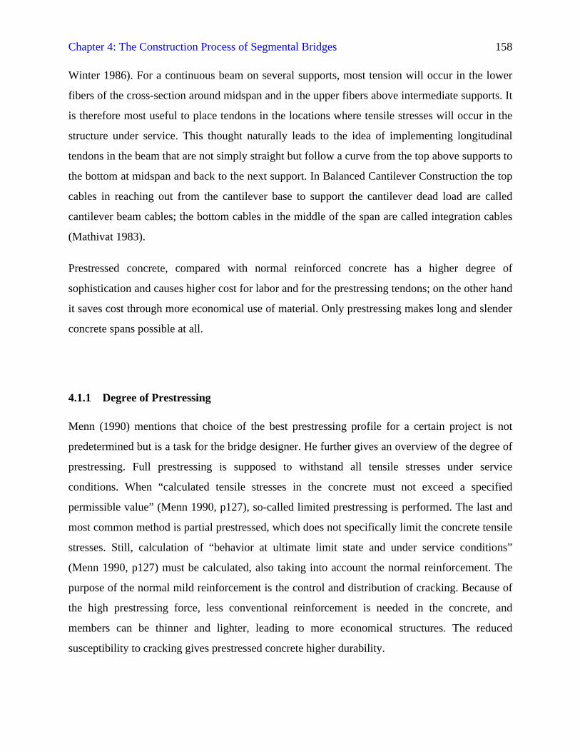
Some factors effectively contribute to initial and long-term reduction of the prestressing force.
Immediate losses of prestress, also called initial losses, occur once the prestressing force is
applied, after the concrete has been placed and cured. Loss of prestress needs to be anticipated
during design. Long-term losses in concrete depend on its design mixture, curing, the
environmental climate, and the member geometry. Textbooks give information on the reasons for
prestress losses and provide many formulas to calculate their effect. The following Table 4-1
based on Barker and Puckett (1997, pp455-466) summarizes these effects:
Table 4-1: Influences Causing Loss of Prestressing Force
Initial loss of prestress Long-term loss of prestressSlippage of strands in the anchorages(before wedges or nuts grip firmly)
Relaxation of steel strands(loss of stress under constant strain)
Elastic shortening of concrete member(relieves previously stressed tendons)
Creep of concrete member(plastic deformation under constant stress)
Friction between tendon and duct interior(“wobble effect” because of curved ducts)
Shrinkage of concrete member(volume change due to evaporation)
4.1.2 Pre-Tensioning
Prestressing basically can be carried out as pre-tensioning and post-tensioning, referring to the
time when the prestressing force is imposed with respect to casting. In pre-tensioning the tendons
are anchored to e.g. a stiff frame around the casting bed and are prestressed before the concrete is
placed. When the concrete has gained sufficient strength the tendons are relieved from their
anchorages and stress the concrete through bond between steel and concrete. Menn (1990) notes
that this method is especially feasible for precasting concrete elements because of the solid
anchorages required.
4.1.3 Post-Tensioning
Post-tensioning denotes the method of stressing the tendons only after the concrete has reached a
specified strength. To allow for the necessary movement of the tendons inside the concrete they
Chapter 4: The Construction Process of Segmental Bridges 160
are installed in tendon ducts that are made from steel or polyethylene. The ducts need to be fixed
to the normal reinforcement to prevent misalignment during casting. After post-tensioning the
ducts are filled with cement grout under pressure for and protection against corrosion of the
tendons. Grouting the ducts will introduce bond between the steel and the surrounding grout.
Unbonded post-tensioning is less common. Very similar to prestressing tendons are the
techniques used for protection of stay cables of cable-stayed bridges against corrosion, as
described e.g. by Funahashi (1995).
Two different ways of construction exist for post-tensioning. The prestressing tendons can be
located either inside the concrete or outside of it. External post-tensioning has the advantage of
easy accessibility for inspection, maintenance works and replacement. Nevertheless problems
with corrosion protection are the reason for use of interior post-tensioning in most projects.
Post-tensioned tendons need special anchorages that are cast into the concrete structure.
Anchorages have the shape of cones that are sitting on the end of the duct for better accessibility
to single tendon strands with the prestressing jack. Anchorages are mostly surrounded by spiral
reinforcement, which serves to distribute the compressive stresses into the concrete member.
Small wedges around each strand or nuts (Menn 1990) fix the strands to the front plate of the
anchorage. Special anchor blocks, so-called blisters are cast into the structure to provide enough
space for the anchorages, e.g. on the inside of box girder segments of the second generation
(Podolny and Muller 1982). Previously, tendon anchorages were also found in the joint faces,
where problems with accessibility occurred. Textbooks on prestressed concrete structures
provide more information on the layout and calculation of prestressing systems.
4.2 CONCRETE BRIDGE ERECTION TECHNIQUES
Concrete segmental bridges have already been introduced in Section 3.6.1. The following
sections will present the important methods that are used in erecting concrete segmental bridges
nowadays and the equipment employed. Special focus is put on constructability issues, pertaining
Chapter 4: The Construction Process of Segmental Bridges 161
to characteristics and requirements, advantages, and disadvantages of each method to prepare for
the case study that is presented in Chapter 5.
4.2.1 Cantilevering Method
Before used in construction of concrete bridges, the cantilevering method had already been used
in Asia for wooden structures of earliest times, as Podolny and Muller (1982) report. Amongst
the major steel structures that were erected with the cantilevering method are the Firth Rail
Bridge and the Quebec Bridge that are presented in Section 2.1.5. Erection of concrete bridges
with the cantilevering principle led to development of specialized sequences that are discussed
further below.
As already introduced in Section 3.6.2, cantilevering for concrete segmental bridges is a
construction method where segments, either precast or cast-in-place, are assembled and stressed
together subsequently like a chain to form the self-supporting superstructure. Prestressing cables
located in the upper part of the segment cross-section support the cantilever. In the variant of the
progressive placement method stay cables are often used to support the cantilever prior to closure
of the span.
Time-dependent material behavior of the segments under successive load steps requires
comprehensive calculations for all construction stages. Every segment will develop strength with
increasing age of the concrete. Governing for the structural behavior of the cantilever is that
every segment carries and transfers loads from all following segments and construction loads
until closure of the span. From these very basic facts in conjunction with geometry and expected
loads on the structure the calculation of moments and local stresses, as well as calculation of the
deflections that they cause is possible. Optimization of geometry, prestressing, and camber are
then performed.
Depending on the specific segment configuration and erection sequence chosen for the
cantilevering method the cantilever may never be exactly balanced so that the superstructure
needs to be balanced to ensure stability. It is possible to fix the supports at the piers of
Chapter 4: The Construction Process of Segmental Bridges 162
cantilevering superstructures and install vertical prestressing tendons. Furthermore it is very
common to make use of an additional temporary pier with vertical prestressing that is located
close to the permanent one (Casas 1997). This pier helps withstanding overturning moments
from unbalanced load cases on the bridge superstructure.
Several advantages have contributed to the success of the cantilevering method. Certainly the
most important one is that no falsework or centering is required, leaving traffic under the spans
widely unobstructed during construction. Access from the ground is only necessary for
construction of the piers and abutments and in preparation for the start of cantilevering, which
starts from these locations.
Only relatively little formwork is required due to the segmental nature of the superstructure.
Cantilevering is a very feasible method if the bridge spans are too high above ground for e.g.
economical use of falsework, and if the terrain under the spans is otherwise inaccessible or
unfeasible, being e.g. a deep gorge with danger of flood events. Especially in these cases rapid
construction can be achieved with cantilevering.
Fletcher (1984, p13) notes that especially in cantilevering “complete calculations are required for
the construction stage[s] and these are complicated as many stressing effects are time-
dependent.” In addition to this, the influence of stepwise construction needs to be considered.
However, the statical system that needs to be analyzed is rather simple and in case of the
cantilever prior to closure at midspan even statically determinate.
4.2.1.1 Precast Construction
Precast construction means that bridge members or segments are prefabricated at a location
different that the site, transported to the site, and installed there. Mathivat (1983) gives the
maximum economical span of bridges built in precast segment as about 150 m, since cost for the
placement equipment increase considerably the longer the spans are. Construction with precast
segments has several advantages in comparison with cast-in-place segmental bridges. Casting of
the segments can be performed under controlled, plant-like conditions at the precasting yard.
Chapter 4: The Construction Process of Segmental Bridges 163
This industrialized process allows easy quality control of segments prior to placement in the
superstructure and saves money through reuse of the precasting formwork. Surface finishing
works, such as texturing, sandblasting, painting, and coating can be performed on the ground
level without scaffolding when the segments are still accessible from all sides prior to installation
in the superstructure.
Another major advantage mentioned by Mathivat (1983, p212) is that the complete casting of the
superstructure can be removed from the critical path of the overall construction schedule, since
superstructure “segments can be precast during construction of the substructure.” Assembly of
the bridge superstructure takes much less time than cast-in-place construction, as precast
segments do not need to cure on site before being prestressed together. Through the early casting
of segments material properties are also influenced positively. As segments are usually stored at
the precasting yard or on site for a while the concrete will have gained more strength until
installation than cast-in-place elements have when being loaded. The time-dependent effects of
concrete shrinkage and creep will occur with reduced extent because of the increase age of the
concrete segments (Mathivat 1983) and will cause smaller deflections of the superstructure than
with cast-in-place construction.
However, cost for the precasting yard, storage, transportation, and installation of precast
segments needs to be evaluated in comparison with cost for the form travelers for cast-in-place
construction to achieve an economical solution.
The precasting yard requires investment in equipment. Adjustable formwork to form the bridge
geometry and alignment needs to be installed. Lifting equipment is also required to put the
segments into the storage area and later load them on truck to be hauled to the construction site.
It is common practice to use the match-cast method to achieve high accuracy in segment
prefabrication. Match-casting means that the segments are cast in the formwork between a
“bulkhead at one end and a previously cast segment at the other” (Levintov 1995, p46). Segment
joint faces need to be clean of any dirt for match-casting.
Levintov (1995) distinguishes concrete segment prefabrication into short-line casting and long-
line casting. Short-line casting would comprise formwork of the length of only one segment; with
Chapter 4: The Construction Process of Segmental Bridges 164
the previously cast segment being moved into position for match-casting on a mobile carriage.
Short-line casting can be carried out in the horizontal position or with the segments tilted facing
upward (Podolny and Muller 1982), however, the normal horizontal position facilitates match-
casting. The overall bridge alignment requires careful adjustment of the formwork prior to each
concrete placement. Short-line casting does not take much workspace.
Long-line casting on the other hand means erection of formwork for about a complete bridge
span. According to Levintov (1995) the formwork can be erected stationary for the superstructure
soffit only, with smaller movable forms for web sides and interior formwork. This formwork will
be cheaper than the flexibly adjustable formwork for short-line casting, but will require much
more workspace. Levintov cautions that the long-line casting is feasible for straight
superstructures or superstructures with constant curvature. Segments are match-cast
progressively on the long-line formwork by step-by-step advancement of the movable formwork
units and a movable bulkhead.
Phipps and Spruill (1990) describe the precasting cycle that was used in construction of the
Biloxi Interstate I-110 viaduct. According to them, the freshly cast segments were steam cured in
a movable shed covering the casting bed of the short-line formwork. The pretensioning strands
were released by cutting them, quality control and testing of concrete samples was performed,
and internal formwork units were removed from the new segment. After lifting the previously
cast segment from its position for match-casting into the storage area, the new segment was
rolled out of the formwork. It was positioned for match-casting according to the required overall
alignment. Cleaning of the joint face and the bulkhead was done prior to casting the next
segment. Reinforcement bars were preassembled in reinforcement cages to speed up placement.
Pre-tensioning strands were used in the box girder segment, being stressed prior to concrete
placement. After concrete placement and consolidation with vibrators the segment was screeded
and given a surface finish before the curing shed was set up over the casting bed. With the
sequence described a casting cycle of one superstructure segment per day could be achieved. In
the final superstructure post-tensioning cables were installed to stress the precast segments
together.
Chapter 4: The Construction Process of Segmental Bridges 165
Precast segments have joints that require special attention. An epoxy agent is usually applied to
the joint faces shortly before putting a segment into its location in the superstructure. Joints are
usually only a few millimeters thin. Podolny and Muller (1982) explain the functions of the
epoxy agent that is applied to the joint faces when placing precast segments. During segment
placement the epoxy serves to lubricate the joint faces, which are cleaned by sandblasting and
“compensate for minor imperfections in the match-cast surfaces” (Podolny and Muller 1982,
p485). In the finished structure the hardened epoxy seals the joints against moisture and thus
additionally protects the tendons in their ducts. Furthermore, the epoxy is able to transmit
compressive forces and shear forces. Information on mixing, handling, and properties of the two
main ingredients, the epoxy resin and the hardener, is provided by Podolny and Muller (1982).
Interestingly, the epoxy agent can reach a higher final strength than the concrete itself.
In addition to the epoxy transmitting shear forces between segments the joint faces are given a
special shaping to transmit shear. So-called shear keys are cast into the joint faces to lock the
segments together. They transmit shear forces and also help in exact alignment of the segments
during assembly. Segments of the so-called second generation facilitate many smaller shear keys
that are located not only in the box girder webs, but also in top and bottom flanges (Podolny and
Muller 1982).
4.2.1.2 Cast-In-Place Construction
Podolny and Muller (1982) provide an example for a typical casting cycle. As outlined in Section
3.6.3.1, any previously cast segment needs to have developed at least the specified strength to be
prestressed to previous elements and support the subsequent one. After finishing all work on a
segment the form traveler is detached from the previous position and moved forwards on rails
that are mounted on the bridge superstructure. In order to remain balanced during advancement
the form traveler may be equipped with a counterweight. Upon arrival at the new position it is
adjusted and anchored to the existing superstructure at its rear to be able to withstand overturning
moments that will occur from the weight of new concrete. The external formwork is cleaned and
aligned to the required geometry of the next segment, also incorporating the desired camber.
Chapter 4: The Construction Process of Segmental Bridges 166
When the form traveler has thus been prepared the reinforcement and tendon ducts for bottom
slab and webs will be installed and connected with the previous ones. In cast-in-place
construction it is possible to have continuous mild reinforcement in the superstructure, whereas
in precast segmental construction only the longitudinal prestressing tendons will cross the
segment joints.
Reinforcement can be pre-assembled into cages that are lifted into place by crane. Prestressing
tendons are already inserted into their ducts prior to placement of concrete because of better
accessibility. After these preparations, concrete is placed. Accessibility of the bottom part of the
box girder may require that the bottom slab is cast before internal formwork for webs and top
slab is advanced and aligned. After curing sufficiently for strength and durability, the tendons in
the newly cast concrete segment can be prestressed. Finally, the casting cycle starts all over again
to cast the next segment.
Concrete placement can be carried out by various means, e.g. with buckets that are hoisted by
crane, or by pumping. While placing the concrete in lifts care needs to be taken that no
segregation of the concrete mixture occurs, and that proper consolidation will be achieved. The
most common method is to vibrate the concrete in the formwork by means of internal or external
vibrating devices. Most important for the quality of the concrete is curing to achieve strength and
durability. Upon gaining enough strength, the tendons in the newly cast segment will be stressed
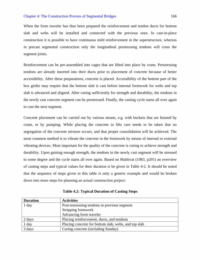
to some degree and the cycle starts all over again. Based on Mathivat (1983, p201) an overview
of casting steps and typical values for their duration is be given in Table 4-2. It should be noted
that the sequence of steps given in this table is only a generic example and would be broken
down into more steps for planning an actual construction project:
Table 4.2: Typical Duration of Casting Steps
Duration Activities1 day Post-tensioning tendons in previous segment
Stripping formworkAdvancing form traveler
2 days Placing reinforcement, ducts, and tendons1 day Placing concrete for bottom slab, webs, and top slab3 days Curing concrete (including Sunday)
Chapter 4: The Construction Process of Segmental Bridges 167
Mathivat (1983) also gives information on means of accelerating this process. Use of special
form travelers “with lateral main beams or self-supporting carriages” (Mathivat 1983, pp201f)
will leave the bottom slab widely unobstructed and make construction easier. Secondly,
“increasing the length of segments” can be considered during the design phase while keeping in
mind the increasing weight and cost of bigger form travelers. Stepwise construction of the box
girder is also possible, with relatively simple formwork for the top slab following a few segments
behind the main form traveler. With this method less concrete has to be placed in one single step
of concrete placement. Yet it requires careful structural design of the vertically segmented
superstructure. Finally, an example of a segmental bridge is given for combination of cast-in-
place and precast segment sections. Webs of the superstructure box girder of the Brotonne Bridge
in France were precast and placed into the form travelers, which were used to fabricate the
remaining cast-in-place parts of the cross-section (Mathivat 1983).
4.2.1.3 Balanced Cantilever Construction
Balanced cantilever construction denotes building a bridge superstructure from both sides of the
pier table in a scales-like fashion. This erection method is also known under the name free
cantilever construction (Podolny and Muller 1982). Fletcher (1984) gives information that the
pier table element, serving as a base from which cantilevering is begun, is usually between 6 and
12 m long. In order to balance the weight of both arms of the cantilever superstructure the
segments will be about equally placed at both ends. Actual placement of new segments will
hardly proceed exactly at the same times as Mathivat (1983) expresses. Therefore the pier can
undergo overturning bending moments and needs to be designed accordingly. Temporary towers
with vertical prestressing or counterweights can provide additional support. Figure 4-1
schematically shows a typical construction stage in Balanced Cantilever Construction.
Chapter 4: The Construction Process of Segmental Bridges 168
Figure 4-1: Balanced Cantilever Construction
Balanced cantilevering can be carried out with cast-in-place or precast segments. For cast-in-
place balanced cantilevering a set of two form travelers is required, one for each arm of the
cantilever. For multi-span bridges the form travelers can be dismantled after finishing
cantilevering from one pier and can be set up for new use on the next cantilever.
In case of a bridge with variable box girder depth the pier table segment will be the most massive
segment of the superstructure. This segment needs to be constructed prior to cantilevering to
provide a working platform from which the two form travelers can start. It also includes
diaphragms that facilitate the flow of forces from the cantilever arms into the piers. Because of
size, geometry, and construction separate from the rest of the superstructure the pier table
segment will take a considerable amount of time to construct. It can be put into place either with
large precast segments or as cast-in-place with formwork mounted on the pier shaft.
An interesting pier design specifically feasible for cantilevering is mentioned by Fletcher (1984),
who points out that a pier consisting of transverse twin walls is advantageous as it provides
stability for cantilevering but allows horizontal movement of the superstructure from thermal
elongation through flexing of the wall panels.
Balanced Cantilever Construction
TemporaryTower withVerticalPrestressing
Form Traveler
Pier
Chapter 4: The Construction Process of Segmental Bridges 169
4.2.1.4 Progressive Placement Method
The progressive placement method, in comparison with the balanced cantilevering method, is a
one-directional process as shown in Figure 4-2. All cantilever segments are subsequently placed
at the tip of a cantilever that is built across all spans. Both cast-in-place and precast segmental
construction can be used. Often stay cables from the tip of a temporary tower on the
superstructure support the cantilever. With growing cantilever superstructure this support
mechanism has to be advanced. Another method of support is use of temporary towers, which are
mentioned in Section 4.2.3.3. According to Mathivat (1983) this method is competitive for spans
between 30 to 50 m in length, whereas incremental launching and balanced cantilevering are also
used for much longer spans.
Figure 4-2: Progressive Placement Method
Progressive placement has several advantages, as Mathivat (1983) points out. First of all, the
placement process does not have to switch sides as it occurs in the balanced cantilevering
method. Thus process control is simplified. In addition to this, good access to the placement
location is given on the already completed part of the bridge superstructure. With the progressive
placement method horizontal curves can easily be accommodated.
From a structural point of view the progressive placement method is advantageous in
substructure design. Only vertical forces from the dead load of the superstructure under
Progressive Placement Method
TemporarySupport
Progressive Placement Method
Chapter 4: The Construction Process of Segmental Bridges 170
construction are experienced. In comparison with incremental launching and balanced
cantilevering, a simpler flow of forces takes place between superstructure and the piers. No
horizontal forces are introduced in the piers and no unbalanced bending moments have to be
withstood by the piers. It is therefore possible to immediately install the permanent bearings
(Mathivat 1983).
Some disadvantages of the progressive placement method need to be dealt with during design
and construction. As construction only progresses at the tip of one cantilever, progress is slower
than in balanced cantilevering. Progressive placement resembles incremental launching in that
the superstructure undergoes stresses very different from the permanent service conditions,
including even stress reversals. In both cases the structure needs to incorporate temporary
prestressing tendons to account for these stresses. Mathivat (1983) also points at the difficulty in
erecting the first span with progressive placement. Other construction methods may have to be
employed for this stage.
4.2.1.5 The Linn Cove Viaduct
An interesting example for use of the progressive placement method is the Linn Cove Viaduct
(Anon. 1984), shown in Figure 4-3. Its location in an environmentally sensitive area in North
Carolina, the inaccessibility of the sloping site at the mountain face, and the highly curved
alignment of the viaduct provided a set of difficult conditions for this project. Match-cast
prefabricated segments for the highly curved viaduct were delivered by truck directly to the end
of the already completed part of the structure, where they were placed and attached with
temporary thread bars and tendons. Deviating from the method outlined above, no cables were
used above the spans, but steel bents were installed under the spans during construction to
provide support. Only drilling so-called microshaft piles for the pier foundations needed to be
done directly on ground, as the piers themselves also consisted of precast segments that were
craned into position from above and post-tensioned vertically. Implementation of the progressive
placement method in connection with precast pier segments that were lowered into place from
Chapter 4: The Construction Process of Segmental Bridges 171
above, called top down construction, helped protecting the natural environment at the site as far
as technically possible.
Figure 4-3: The Linn Cove Viaduct, North Carolina, U.S. (taken from Rives 1997, p41)
4.2.1.6 Concluding the Cantilevering Process
The cantilevering process will finally have reached its end when both girders meet at midspan
and need to be connected. Three different ways exist to achieve this connection in the structural
system (Mathivat 1983). A hinged connection can be installed that allows horizontal movements
in the superstructure. As Mathivat (1983) writes, this system is structurally relatively simple, yet
the hinges are complicated details and the overall structural redundancy of the system is reduced.
Podolny and Muller (1982) also mention the lower ultimate load-carrying capacity of the hinged
system and the higher susceptibility to creep and relaxation phenomena. Furthermore, the two
superstructure halves can have a slight angle between them as deflections occur, which is
detrimental to “the appearance of the bridge and the user’s comfort” (Podolny and Muller 1982,
p36).
Chapter 4: The Construction Process of Segmental Bridges 172
Secondly, part of the midspan superstructure can be designed as a suspended span sitting on
bearings between the cantilevers. In this configuration the deflection angle between the shorter
cantilevers and the suspended span will be much smaller, and “differential settling of the
supports” can better be accounted for (Podolny and Muller 1982, p38). Still, the connections
require special details in the structural system.
Finally, the whole superstructure can be made continuous at midspan. Achieving this statically
indeterminate system is the most common way in building cantilever bridges for several reasons.
Mathivat (1983, p41) names specifically that the deflections in the stiffer continuous
superstructures are “indeed far smaller than those met in hinged structures” and both visual
appearance and drivers’ comfort are better than in hinged superstructures. He also notes the
necessity for expansion joints in very long continuous multi-span superstructures and advises to
provide expansion joints about “300 to 600 m apart” (Mathivat 1983, p45) in points of small
moments in the superstructure. Horizontal movements of the bridge superstructure can be
accommodated “by the flexibility of the piers themselves, or by using elastomeric bearings or
sliding supports” (Mathivat 1983, p45).
Continuity is generated by casting a closure segment into the gap at midspan, through which
continuity tendons, the so-called integration cables as mentioned in Section 4.1 run in the bottom
part of the box girder (Mathivat 1983). Prior to casting this segment, misalignments of the two
superstructure halves are corrected with hydraulic jacks. It should, however, be tried to keep
these additionally imposed stresses small by paying close attention to the correct alignment
including camber when casting the superstructure halves. Additionally, as mentioned in Section
3.6.2.7, the two girders are often jacked apart to compensate for future effects “of long-term
creep and shrinkage of the superstructure on the substructure” as Matt et al. (1988, p37) report.
They further mention casting the closure segment of their bridge project at night to avoid
problems from temperature gradients in the superstructure. For casting and curing of the midspan
closure segment the girders need to be fixed in their position. Finally, continuity tendons can be
inserted into the newly cast segment and post-tensioned. Upon closure of midspan internal stress
redistribution takes place, shifting the moments from the supports more towards midspan. The
formerly free cantilevers are now restrained in deflection and rotation. Podolny and Muller
Chapter 4: The Construction Process of Segmental Bridges 173
(1982) provide a sample calculation for the effect of stress redistribution with consideration of
time-dependent effects.
4.2.2 Cantilever Erection Equipment
Different erection equipment is used in bridge construction. With the specific focus on cast-in-
place and precast cantilever segmental bridges, form travelers and launching girders will be
introduced in the following sections. Other equipment that can be used for placement of precast
segments is e.g. cranes.
4.2.2.1 Form Travelers
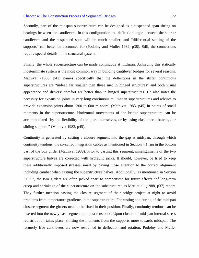
Cast-in-place cantilever construction requires formwork that is attached to the tip of the growing
cantilever for casting. The following paragraphs will deal with girder cross-sections only. As the
cantilever grows the forms travel are set forth in steps. These form travelers give shape to the
segment, support the weight of the newly cast concrete until it has gained enough strength to be
post-tensioned to the previous cantilever segments, and transfer the segment weight to the
already existing superstructure. Determining for the capacity of the form travelers is the
maximum size and initial weight of the biggest segment in the bridge superstructure, including
other construction loads.
Form travelers available in today’s construction industry are made by specialized manufacturers
and are reusable and very flexible (Levintov 1995) with respect to changing geometry of the
bridge superstructure and its alignment, including camber. They can be enclosed in a heated tent
to enable concrete placement and curing to proceed during adverse weather conditions, especially
low temperatures. In comparison with a precasting yard, form travelers often offer the less costly
solution, since transportation and storage of prefabricated segments is avoided, and they integrate
all the functions of the precasting plant into a relatively small device. Fletcher (1984) notes that
by use of form travelers the formwork is reused several times, while adjustments to variable
Chapter 4: The Construction Process of Segmental Bridges 174
segment geometry, especially depth, remain possible with relatively little effort. Disadvantages of
cast-in-place cantilevering with form travelers are discussed in Section 3.6.3.1. Figure 4-4 shows
a typical view of a form traveler.
Figure 4-4: Form Traveler Front View
Form travelers consist of a sufficiently stiff steel frame to which form panels for the box girder
segments are attached at the front. According to Levintov (1995, p43), the steel frame is mostly
composed of two parallel “diamond- or triangular-shaped frames that are connected and stiffened
Work Platform Concrete Bucket
TremiePipes
Web
Bottom SlabWork Platform
Main Truss
Bracing
Shoring
OpenConcreteSurface
InternalFormwork
Rails
Top Slab WithCantilever Flanges
Chapter 4: The Construction Process of Segmental Bridges 175
by diagonal bracing and transverse trusses at the upper front and rear.” Wheels allow longitudinal
movement of the form traveler on rails on top of the superstructure. For stability of the traveler it
can be held down by a counterweight at its rear end (Mathivat 1983). After advancing, the
traveler is anchored down to the cast parts of the superstructure with tendons at its back, as
Levintov (1995) writes. Thus, the overturning moment from the load at the traveler tip can be
resisted. It is mentioned that for structural reasons the form traveler main beams are located
above the webs of the concrete box girder, so that construction loads can be transferred into the
main load-carrying system of the bridge directly. The longitudinal main beams of the form
travelers need not necessarily be located above the webs. Form travelers are also used in
configurations with the main beams in a lateral position, leaving the bridge deck free (Podolny
and Muller 1982). Mathivat (1983) further distinguishes so-called self-supporting assemblies,
where the stiffening effect of the form panels contributes to the stiffness of the whole form
traveler.
Suspended from the traveler are not only the adaptable forms for exterior and interior of the
concrete segment, but also working platforms on different levels that can be accessed from
above.
4.2.2.2 Launching Girders
Apart from various types of cranes that can be used to place precast segments, launching girders
are widely used for this purpose. Levintov (1995) mentions limited access under the cantilever
and great height of bridge superstructures above ground as reasons why launching girders would
be used. They are very feasible for bridges with several spans, as due to their length they can be
advanced over gaps that are still to be bridged. During construction they are moved forward on
rails whenever a major part of the bridge superstructure has been completed.
Launching girders, also called launching gantries, are large trusses that are placed longitudinally
on the bridge superstructure. One or more movable crane devices for transportation of the precast
Chapter 4: The Construction Process of Segmental Bridges 176
segments can be attached to them, running along the chords of the girders. Precast segments are
delivered to the girder by special heavy-duty vehicles.
If launching girders are built of high strength steel their weight can be reduced considerably. At
the same time, however, larger deflections occur that are limited by additional support of the
girders with a king post system with stay cables (Mathivat 1983).
Launching girder trusses can have triangular or rectangular cross-sections and can be constant in
depth or higher towards the middle. They can be disassembled into parts that are connected with
high-strength friction bolts (Mathivat 1983) for transportation, very similar to tower crane
booms.
Most launching girders are overhead trusses that have three leg supports. The three legs are
called rear, central, and guide leg. Some of these legs, often the guide leg, are not permanently
fixed to the girder to allow the advancing movement as will be described below. Very often these
legs form a bent above the superstructure, leaving space for the precast segments that are turned
90° sideward to be moved through the gap. Pivoting the whole launching girder around the rear
support leg (Mathivat 1983) accommodates bridge superstructure curves in the horizontal plane.
A major feature of launching girders is their length in comparison with the span length of the
bridge superstructure. Levintov (1995, p45) writes that launching girders composed of “single or
double trusses may range from slightly longer than a span length to slightly longer than twice a
span length.” Erection sequences for these two extremes shall be briefly described in the
following paragraphs.
4.2.2.2.1 Launching Girder Slightly Longer Than One Span
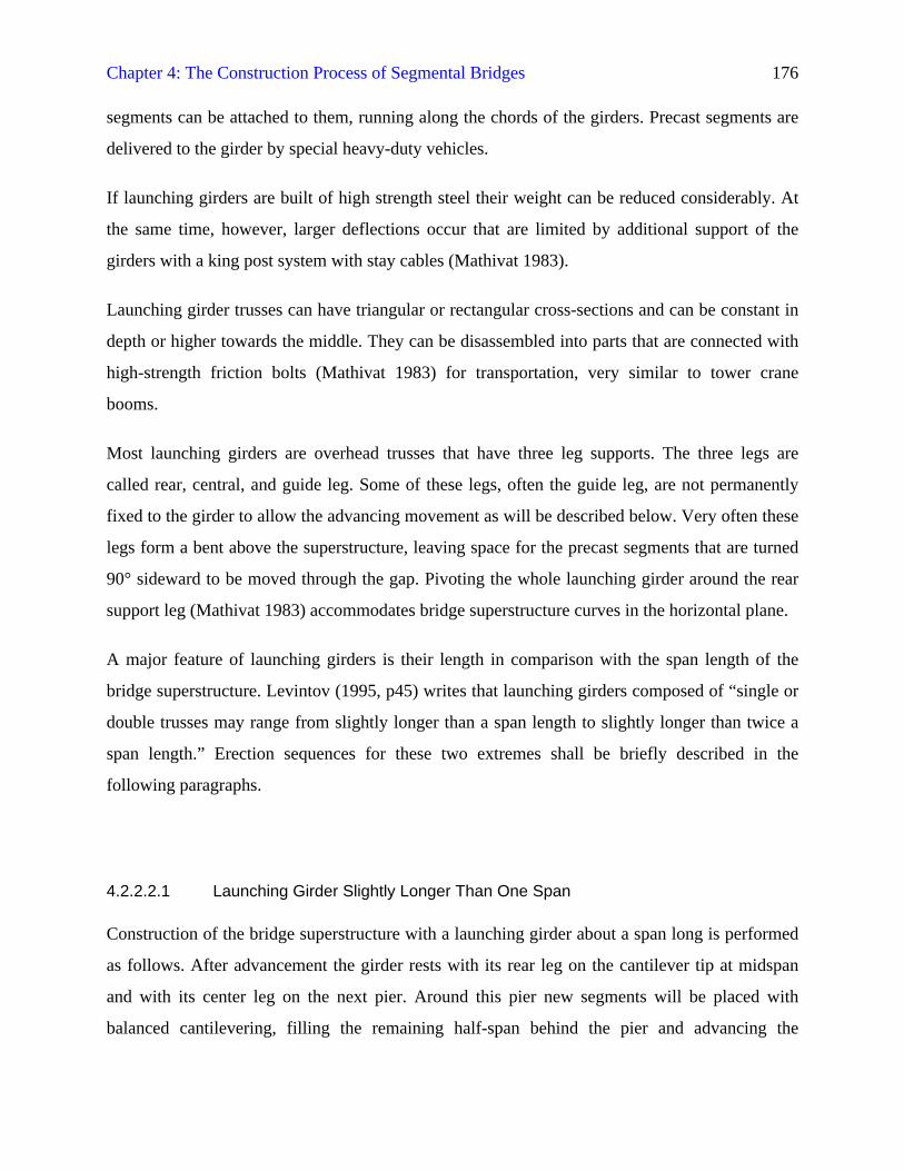
Construction of the bridge superstructure with a launching girder about a span long is performed
as follows. After advancement the girder rests with its rear leg on the cantilever tip at midspan
and with its center leg on the next pier. Around this pier new segments will be placed with
balanced cantilevering, filling the remaining half-span behind the pier and advancing the
Chapter 4: The Construction Process of Segmental Bridges 177
cantilever to the next midspan. Afterwards, the next pier table segment is placed and the
cantilever advances half a span so that it comes to rest on guide leg and rear leg. The guide leg
will remain on the pier as the girder advances further. When the central leg arrives at this pier
and the rear leg is at midspan the next placement position has been reached. Figure 4-5 shows the
construction sequence with a launching girder that is slightly longer than one span.
Figure 4-5: Working Scheme of Short Launching Girder
Placement ofSegments
Launching Girder
Launching Girder, Placement Phase
Direction ofAdvancing
Launching Girder, Advancement Step 1
Direction ofAdvancing
Launching Girder, Advancement Step 2
Chapter 4: The Construction Process of Segmental Bridges 178
A major drawback of this method is found in the previous description. The bridge superstructure
will take considerable loads during construction, since the heavy launching girder rests with one
leg at the midspan cantilever tip.
4.2.2.2.2 Launching Girder Slightly Longer Than Two Spans
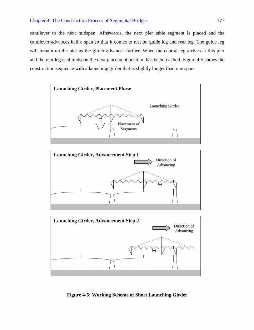
Construction of the bridge superstructure with a launching girder about two spans long does not
incur the aforementioned detrimental load condition. At all stages the load-carrying girder legs
will be located above piers. This is shown in Figure 4-6. In the normal placement position the
launching girder rests with its rear leg above a previous pier and with its central leg above a free
pier. It is easily possible to also support it at the guide leg once the third pier table has been
placed. Placement of the segments will then proceed on both sides of the pier table in the middle
of the girder. To speed up construction, the girder can be equipped with two crane devices to
place segments on both sides simultaneously. After the remaining gap in the superstructure has
been closed and the cantilever has grown into the next span, the girder is advanced one complete
span. During advancement the girder rests on the guide and central leg that remain on the newly
finished pier and the one that lies ahead. This second way of employing launching girders is the
more recent technique (Mathivat 1983).
Even longer launching girders have been used in construction, as reported by Mathivat (1983).
Due to the long span required for launching girders and the mechanical parts, such as crane and
advancement devices, launching girders can be quite costly. If possible, launching girders should
be adaptable for reuse or should be rented. Launching girders can reach lengths of more than 150
m, depending on the requirements of the bridge spans, and weights of up to about 400 t
(Mathivat 1983). In addition to these specialized, expensive and heavy pieces of construction
equipment it is also possible to use simple lifting devices that are located at the cantilever tip. In
the case of the Linn Cove Viaduct, which has been presented in Section 4.2.1.4, a derrick was
mounted to the bridge superstructure that placed segments as they were delivered by truck (Anon.
1984). Other types of deck-mounted equipment are imaginable and mentioned by Levintov
(1995, p44), e.g. “a longitudinal beam fitted with lifting tackle and winches.”
Chapter 4: The Construction Process of Segmental Bridges 179
Figure 4-6: Working Scheme of Long Launching Girder
4.2.3 Incremental Launching
Incremental launching was developed by the German engineers Fritz Leonhardt and Willi Baur
for the Rio Caroní Bridge in Venezuela (Podolny and Muller 1982), which was built from 1962
to 1964. The incremental launching technique, as opposed to other methods presented in this
chapter, consists of casting a continuous chain of segments at one particular location on site and
then pushing the growing superstructure out over site to be bridged. A casting bed with
adjustable formwork for the superstructure segments is set up. This casting bed can also be
enclosed in a heated tent so that controlled casting and curing conditions are achieved. The
normal cycle time, regardless of segment length is one week. Segment lengths according to
Liebenberg (1992) typically range between 15 and 30 m.
Direction ofAdvancing
Lauching Girder, AdvancementPhase
Launching Girder
Launching Girder, Placement Phase
Placement ofSegments
Launching Girder, Placement Phase
Chapter 4: The Construction Process of Segmental Bridges 180
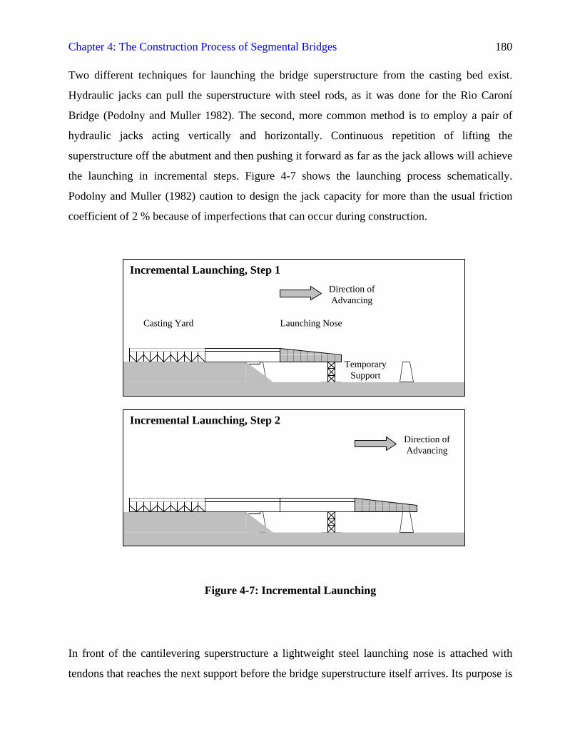
Two different techniques for launching the bridge superstructure from the casting bed exist.
Hydraulic jacks can pull the superstructure with steel rods, as it was done for the Rio Caroní
Bridge (Podolny and Muller 1982). The second, more common method is to employ a pair of
hydraulic jacks acting vertically and horizontally. Continuous repetition of lifting the
superstructure off the abutment and then pushing it forward as far as the jack allows will achieve
the launching in incremental steps. Figure 4-7 shows the launching process schematically.
Podolny and Muller (1982) caution to design the jack capacity for more than the usual friction
coefficient of 2 % because of imperfections that can occur during construction.
Figure 4-7: Incremental Launching
In front of the cantilevering superstructure a lightweight steel launching nose is attached with
tendons that reaches the next support before the bridge superstructure itself arrives. Its purpose is
Direction ofAdvancing
Direction ofAdvancing
Casting Yard Launching Nose
Incremental Launching, Step 1
Incremental Launching, Step 2
TemporarySupport
Chapter 4: The Construction Process of Segmental Bridges 181
to keep the bending moments in the superstructure smaller. Mostly the launching nose has a
length of about 60 % of the bridge spans (Podolny and Muller 1982). Another way of reducing
the bending moments is to implement temporary towers between the bridge piers. These towers
need to be able to take the horizontal forces that arise from launching.
On top of all supports, including abutments, piers, and temporary towers temporary sliding
bearings are installed during construction that will later be replaced with the permanent ones.
Stainless steel plates are installed on the bearings. While the superstructure is advanced,
Neoprene pads coated with Teflon and reinforced with steel plates are inserted between concrete
and steel to reduce friction (Liebenberg 1992). Very low friction coefficients of 2% or less can be
achieved with this method.
Several advantages make incremental launching a very competitive erection method. As with any
cantilevering method it leaves the site below completely unobstructed during construction. Only
for very long spans temporary towers or cable stays from above as supports are needed. Except
for these the equipment necessary is reduced to the jacking mechanism, the adjustable stationary
casting bed, and temporary sliding bearings, all of which may possibly be reused, which reduces
the capital investment considerably. Podolny and Muller (1982) furthermore mention the cost
savings due to avoidance of segment transportation and heavy construction equipment. They also
point at less maintenance cost due to the higher prestressing of the superstructure. The controlled
casting and curing conditions allow steady and quick construction progress.
Bridges that are erected with the incremental launching method should, according to Podolny and
Muller (1982), have a constant cross-section, especially in depth, and have a straight
superstructure. It is possible to accommodate small variations in alignment and horizontal and
vertical curvatures provided that they have a constant radius. Close control of the bridge
geometry during casting and launching is very important. Sloping grades at the bridge site are
also accommodated, in this case “the launch is usually in the downward direction”, more than
2 % slope would require a retarding mechanism to stop the movement of the superstructure
(Liebenberg 1992, p165).
Chapter 4: The Construction Process of Segmental Bridges 182
Liebenberg (1992, p164) also gives a very clear statement of the main difficulty of the
incremental launching method: “During launching, the section undergoes complete stress
reversals as it progresses from a cantilever to the first support and thereafter over the following
spans to its final position.” Clearly, this erection sequence generates a bending moment envelope
in the structure depending on the span lengths that needs to be accounted for in designing the
cross-section properties and the amount of reinforcement and prestressing tendons. The stresses
due to the aforementioned high bending moments require much longitudinal prestressing both at
top and bottom of the cross-section. Another disadvantage is the large workspace that is needed
for the casting bed at the abutment and the adjacent storage areas (Podolny and Muller 1982).
The Aichtal Bridge in Germany that was built mainly between 1981 and 1983 serves as a good
example of the incremental launching method. According to Basse et al. (1985) this bridge with
its total length of 1,161 m is the longest one ever built with incremental launching. It crosses two
valleys at a maximum of 48 m and 50 m above ground, respectively. A fixed bearing is located at
the pier between the two valleys. At the same location a second jacking system was installed for
use in later construction stages.
The normal pier spacing for the 21 spans of the Aichtal Bridge is 51 m, reaching a maximum of
80 m and 84 m respectively at the deepest parts of the valleys. These wide spans required use of
temporary towers that were braced with stay cables from the ground to resist the horizontal forces
from launching. The whole bridge superstructure consists of two parallel single cell box girders
that are 3.50 m deep, 5 m wide at the soffit and carry 13.50-m wide decks. After completion of
one girder all construction equipment was relocated for the second box girder.
An enclosed 25.50-m long casting bed with adjacent assembly yard for the reinforcement cages
was erected behind the abutment with the launching jacks. For winter construction work another
50-m long tent with large heaters was set up for proper curing and the piers were built with
thermally insulated climbing formwork. Casting of segments was done in a weekly cycle. Both
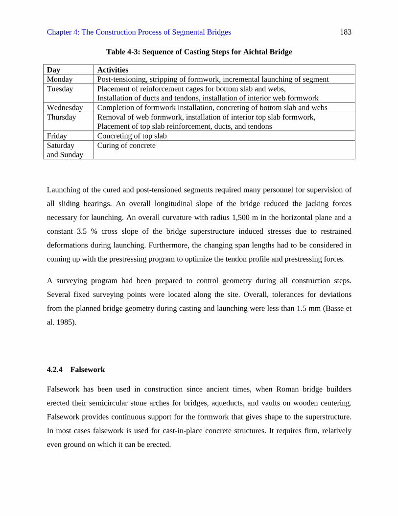
longitudinal and transverse limited prestressing was implemented. Basse et al. (1985, p23) give
information on the sequence of casting steps that is compiled in Table 4-3:
Chapter 4: The Construction Process of Segmental Bridges 183
Table 4-3: Sequence of Casting Steps for Aichtal Bridge
Day ActivitiesMonday Post-tensioning, stripping of formwork, incremental launching of segmentTuesday Placement of reinforcement cages for bottom slab and webs,
Installation of ducts and tendons, installation of interior web formworkWednesday Completion of formwork installation, concreting of bottom slab and websThursday Removal of web formwork, installation of interior top slab formwork,
Placement of top slab reinforcement, ducts, and tendonsFriday Concreting of top slabSaturdayand Sunday
Curing of concrete
Launching of the cured and post-tensioned segments required many personnel for supervision of
all sliding bearings. An overall longitudinal slope of the bridge reduced the jacking forces
necessary for launching. An overall curvature with radius 1,500 m in the horizontal plane and a
constant 3.5 % cross slope of the bridge superstructure induced stresses due to restrained
deformations during launching. Furthermore, the changing span lengths had to be considered in
coming up with the prestressing program to optimize the tendon profile and prestressing forces.
A surveying program had been prepared to control geometry during all construction steps.
Several fixed surveying points were located along the site. Overall, tolerances for deviations
from the planned bridge geometry during casting and launching were less than 1.5 mm (Basse et
al. 1985).
4.2.4 Falsework
Falsework has been used in construction since ancient times, when Roman bridge builders
erected their semicircular stone arches for bridges, aqueducts, and vaults on wooden centering.
Falsework provides continuous support for the formwork that gives shape to the superstructure.
In most cases falsework is used for cast-in-place concrete structures. It requires firm, relatively
even ground on which it can be erected.
Chapter 4: The Construction Process of Segmental Bridges 184
Apart from custom-built timber structures a wide range of steel elements and modules for
falsework is available in the construction industry. Liebenberg (1992) gives a range of up to 300
m in length and about 10 m in height for bridges to be built with this method. He also specifically
points at the necessity for stable foundations of the falsework, sufficient bracing of the falsework
structure, and consideration of the deflection of the falsework in the overall superstructure
camber.
Falsework, either stationary or traveling, can also be configured as casting girders that hold the
formwork into which the concrete is placed. In that, these girders resemble the erection girders of
the span-by-span method, which are used to assemble precast segments. Liebenberg (1992)
further distinguishes the girders depending on their location to the bridge superstructure as
overhead or supporting it from below, or combination of both. He also reminds that use of major
pieces of equipment, such as casting girders needs to be considered carefully because of the high
capital investment that is necessary.
4.2.4.1 Stationary Falsework
Stationary falsework is the simplest method of erecting the bridge superstructure. Advantages
mentioned by Liebenberg (1992) are that stationary falsework can be erected by less specialized
workers to any desired shape. Use of modern standard elements of which the falsework is put
together allows uncomplicated erection. There are, however, several disadvantages related to
stationary falsework. A lot of material is required for stationary falsework, which requires much
time and manual labor to be spent on its erection, in addition to the cost of purchasing or renting
the materials themselves. Therefore, Liebenberg (1992) concludes that it needs to be erected
some spans in advance to keep up with rates of placement of concrete that can be achieved.
Today, falsework is competitively used e.g. for the complex alignments of highway interchanges,
as Cassano (1987) reports for the example California. He states that apart from the feasibility for
the highly curved superstructures, use of major falsework systems also allows placement of very
large volumes of concrete at the same time and thus speeds up construction. Cassano (1987)
Chapter 4: The Construction Process of Segmental Bridges 185
mentions that all falsework in California has to be designed and built according to the Falsework
Manual of the California Department of Transportation and is reviewed and inspected by
qualified engineering personnel.
4.2.4.2 Traveling Falsework
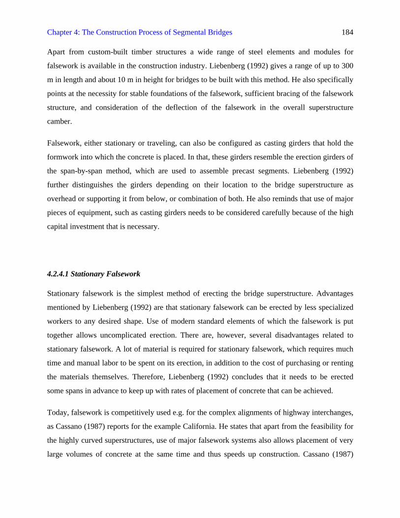
Traveling falsework alleviates some of the problems associated with stationary formwork. This
type of falsework, including formwork, is assembled to larger units that can be moved to the next
span to be cast. As with stationary falsework, this method requires the site to have relatively level
and firm ground to allow movement of the falsework on a wheel assembly. In case the ground
conditions are less favorable, using the span-by-span method might be advisable, where the
superstructure segments are assembled on erection girders. Span-by-span erection is introduced
in the following Section 4.2.4. Traveling falsework is shown in Figure 4-8.
Figure 4-8: Traveling Falsework
4.2.4.3 Temporary Towers
A kind of falsework used frequently in construction is the use of temporary towers to support the
superstructure that is under construction at intermediate positions. These towers can e.g. be used
Traveling Falsework
Formwork
Chapter 4: The Construction Process of Segmental Bridges 186
in the balanced cantilevering method to stabilize the structure against tipping over from
construction loads. They can be additionally strengthened with prestressing rods to withstand the
forces that are imposed on them during construction. Other applications are found during
incremental launching, where together with the launching nose they serve to keep the range of
bending moments small. Instead of using temporary towers as supports Liebenberg (1992, p156)
also mentions stiffening girders “by means of prestraining with a king post and adjustable
inclined ties.”
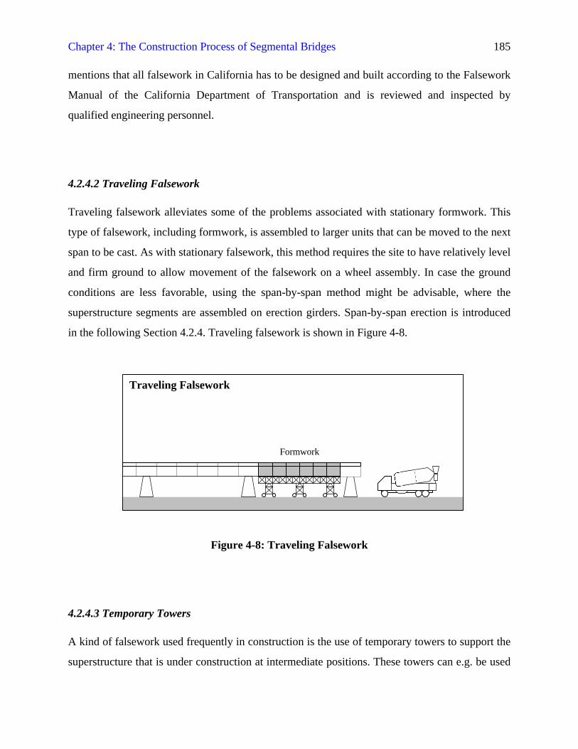
4.2.5 Span-By-Span Erection
Levintov (1995, p47) lays out the characteristics of the span-by-span erection method as
assembling all segments for a span in a set, which is “then aligned, jointed, and longitudinally
post-tensioned together to make a complete span.” The principle of span-by-span erection is
shown in Figure 4-9. Span-by-span erection is typically limited to bridges that consist of box
girders with constant depth. The actual construction can have several variants, the segments can
be assembled on the ground and lifted in place as a group by a heavy-duty crane or they can all be
put into their final position on erection girders along the spans to be completed. The second
method was e.g. used for constructing the Biloxi Interstate I-110 Viaduct. In this project different
types of erection girders were used. The authors report that on some spans triangular trusses were
implemented, and on the other hand steel box girders came into use, which left more clearance
for traffic underneath (Phipps and Spruill 1990). Erection girders were supported at their ends
“by steel falsework resting on the footings at each pier” (Phipps and Spruill 1990, p130). After
completion of a span the erection girders were set forward to the next span and adjusted. By then,
the precast segments for this span had already been supplied and would be lifted in place by
crane. Fine adjustments of the segments on the erection girders were possible by means of
variable individual supports. Finally, post-tensioning would be performed to link all the segments
together to form a complete span. The structure became self-supporting after casting of the
closure joints with the pier table segments had been done and the longitudinal prestressing force
was induced. With the method described, an erection speed of one span per about 3.5 days could
be achieved (Phipps and Spruill 1990).
Chapter 4: The Construction Process of Segmental Bridges 187
Erection girder need not rest on the ground, but can also be supported by already existing
substructure or superstructure, e.g. the piers of a span that is to be constructed. Project specific
design of substructure and superstructure and considerations as e.g. for traffic clearances set the
boundaries for erection with erection girders.
Figure 4-9: Span-By-Span Erection
4.3 CONSIDERATION OF CONSTRUCTION LOADS AND STRESSES
The following sections deal with the relationship between construction loads and the stresses that
these induce in structures and the structures themselves while they are under construction and
still awaiting completion. The central issue for all considerations is structural safety, meaning
failure against structural failure. The generic concept of resistance R that is greater than the most
unfavorable combination of load S that induces stresses has been introduced in Section 3.5.2.
Codes require that all construction influences will be properly taken into account during design.
Even a professional code applicable for bridges (ACI 1995, p51) in its Section 5.3 only points
out that “Consideration should be given to temporary loads caused by the sequence of
construction stages, forming, falsework, or construction equipment and the stresses created by
lifting and placing precast members.” It assigns the responsibility for the construction scheme,
which imposes stresses on the structural members, to the contractor. It is further pointed out that
Span-By-Span Erection
Placement ofSegments
Chapter 4: The Construction Process of Segmental Bridges 188
the stability of precast members and prestressing should be taken into account. “Environmental
loads… should be considered during construction using an appropriate return period or reduced
severity. Lower load factors may be used to account for the acceptability of higher temporary
stress levels” (ACI 1995, p51). The aforementioned load factors are provided in tables in the
same code.
How the actual process has to be accomplished in detail remains the structural engineer’s task.
Close cooperation of designer and contractor in development of the construction sequence
contributes to quality.
For better understanding of the relationship between structures under construction and actions
influencing them it is useful to get a clear definition of the technical terms related to this topic.
The nature of actions has been explained in Section 3.5.3 as any loads or restrained deformations
that can cause stresses within the structural system. The term construction loads should in this
context be understood as the broader sense of any actions that occur during construction of the
structure prior to normal service conditions.
Then again, the concept of construction loads needs to be extended by consideration of the
uncompleted structure during construction, which may not have reached full resistance to
imposed actions.
The term erection method denotes the physical means of putting the foundations, bridge
substructure, and especially its superstructure into place. Every type of erection method requires
certain equipment and site installations to carry out the work tasks. The erection methods goes
along with specific limitations imposed on the flow of work tasks to be scheduled, e.g. that
bridge piers have to be finished prior to begin of incremental launching of a bridge
superstructure.
The construction sequence is the specific succession of work tasks for one particular project
developed under consideration of the erection method chosen for its conditions and restraints for
economic construction.
Chapter 4: The Construction Process of Segmental Bridges 189
Construction stages are notable steps within the progression of work tasks from the initial site
operations startup to the finished structure. These steps can be distinguished by the appearance of
the structural system, loading conditions, or other factors.
Load steps can be defined as specific sets of loads on a structure in its current construction
stages. These load steps or load cases are combinations of actions that are anticipated to occur at
the same time with a certain probability, and are incorporated into analytical calculations with
partial factors of safety.
4.3.1 Types of Construction Loads and Influences
Generally, construction loads are by nature of relatively short duration in comparison with the
overall planned service life of a structure. Construction loads may influence a structure over a
brief time only, e.g. from equipment or material for a new segment that is temporarily stored on
an already completed part of the superstructure of a bridge. Construction loads can affect the
structure in very unfavorable conditions, e.g. when a crane is located at the tip of a cantilever to
place segments. Thus resulting stresses in the structure can even exceed stresses due to
permanent and dynamic loads under service.
Real loads are generally distinguished into two classes, dead loads and live loads. During
construction the structure has to carry its own weight, its dead load, and the superimposed dead
loads of bridge parts that are not structurally important but necessary for service, as e.g. the
bridge furniture, the so-called accessories.
Many different live loads influence the structure. In most of all cases, live loads are idealized
either as uniformly loaded areas on the superstructure or as singular loads from larger pieces of
equipment. Live loads can result from erection equipment, e.g. the launching nose in incremental
launching and lifting devices placed on the structure such as cranes and launching girders. Forces
are also imposed on the structure through restraints from fixed bearings during construction, e.g.
on piers for cantilevering. Along with these structural details, the boundary conditions can still
change; e.g. considerable settlements can occur when the soil is initially loaded. Temporary
Chapter 4: The Construction Process of Segmental Bridges 190
supports, e.g. additional temporary towers for long spans or stay cables also generate stresses in
the superstructure. Another factor to be considered is the prestressing tendons that are installed in
the concrete members to withstand stresses during construction and under service. More
longitudinal forces can be caused by the erection itself, e.g. horizontal jacking forces during
incremental launching. Formwork and supporting installations, e.g. the forms and frames in a
launching girder also impose live loads, as well as the fresh concrete that it carries.
Finally, environmental influences also create changing loads on the structure, e.g. wind, snow,
and temperature gradients. Extreme events, such as floods, storms, and earthquakes can also hit a
structure during construction and may need to be considered in the calculations. Apart from these
Acts of God, accidents may happen. Podolny and Muller (1982) note that to prevent a scenario
such as falling of a form traveler during cantilevering, inspections are necessary. They also note
that critical fixtures, e.g. suspension rods that reach through the superstructure and anchor bars
that hold the traveler, need to have a large safety margin and may be provided in double numbers.
In general, “cast-in-place cantilever construction has established an extremely good safety
record” (Podolny and Muller 1982, p482).
The aforementioned extreme load cases are mostly considered with a lower factor of safety than
for service conditions (ACI 1995). The reason for this approach lies in the reduced probability of
occurrence during the relatively short construction period in comparison with the total duration
of service for which the bridge structure is designed. More explanation for this rationale lies in
the fact that although the resistance is reduced during construction the structure produces less
danger for the general public, as it has not been opened for traffic by then. Furthermore, the
bridge under construction is under direct control of engineering personnel on site that can
immediately take appropriate measures if necessary to ensure safety of further construction
works.
When looking at the structure and its behavior during construction, a striking similarity with the
model presented in Section 3.5.1 appears. In fact, when looking at any structure the four main
elements are geometry of the structural system, structural details and restraints from boundary
conditions, material properties, and loads. For analysis of how a structure behaves while being
under construction the same elements need to be taken into consideration.
Chapter 4: The Construction Process of Segmental Bridges 191
After having considered the loads and restraints, i.e. all actions, two elements remain to be
discussed. The geometry of the structural system itself is developing continuously with progress
of construction depending in a manner that depends on the erection method and needs to be
considered. Incomplete structures, e.g. the cantilever beam prior to midspan closure for
continuity are inherently weaker than in the finished state because of less structural redundancy.
All these different construction stages need to be analyzed as a combination of load cases and the
resistance of the structure at that construction stage for structural safety.
Apart from that structural resistance the material resistance may also be weaker than in the final
state. Especially for cast-in-place segmental bridges the still young concrete usually has not
developed its full specified strength when it is being prestressed and loaded with more segments
for quick erection. The structural resistance and material resistance can also be understood as the
two components of structural safety, namely strength and stability, as outlined in Section 3.1.3.
Summarizing, stresses induced by construction loads may be higher than those from service loads
as the incomplete structural system is mostly different and weaker than finished structures,
concrete has not gained full strength, and the boundary conditions may be different from the
service state. In other words, the great importance of construction stages lies in the criticality that
results from the still low structural and material resistance, while loads may be actually more
adverse and boundary conditions different.
4.3.1.1 The Zilwaukee Bridge
Underestimating the construction loads and their effects on the unfinished structure caused
several accidents and failures of bridge structures under construction in the past. An example for
an accident of a bridge under construction is provided by Anon. (1988), who describes
construction of the Zilwaukee Bridge in Michigan. The new bridge provided a replacement an
old drawbridge on Interstate I-75 that was necessary because of growing traffic. According to
Anon. (1988, p69), the Michigan Department of Transportation (MDOT) made plans for both
Chapter 4: The Construction Process of Segmental Bridges 192
alternatives of a steel plate girder and a precast segmental concrete bridge “to foster competition
and thus reduce the project cost.”
Construction of the concrete structure began in 1981 after a longer bidding process. The
dimensions of the two parallel box girder superstructures are 2.4 km in length with a 38-m high
navigation clearance and a width of 22 m. Balanced cantilevering under a launching girder was
chosen for erection of the 1,592 precast segments. A heavy-duty truck delivered segments
weighing about 110 to 145 metric tons on the bridge. They were placed with the 287-m long,
1,540 metric tons heavy launching girder. “Thus, during construction, the new bridge is subjected
every day to far heavier loads that it will ever experience after it is opened to traffic” (Anon.
1988, p70).
During construction all expansion joints were blocked against movements “by inserting
temporary high-strength concrete blocks”, which are fixed with tie-downs (Anon. 1988, p71). In
late 1982 an accident occurred when these blocks failed in one of the joints, which caused the
respective superstructure to tilt and sag at one end, damaging bearings, joints, and a pier footing
that was forced out of the vertical. The subsequent investigation concluded that the main cause
for this incident “was construction loads at the particular location that were too heavy” (Anon.
1988, p71). Difficult repair works were undertaken to realign and reinforce the pier at its base.
Adjacent soil was temporarily frozen for stabilization and a major concrete counterweight was
placed. Afterwards, pile holes were drilled and filled with concrete, on which the reinforced pier
base was erected. “A structural steel frame was fabricated and erected on top of the new footing,
and fitted with 12 hydraulic jacks” (Anon. 1988, p72) that should help realigning the
superstructure. After new bearings and connecting cables to the counterweight had been installed
the superstructure was brought back into alignment and construction work commenced again
until opening in 1988.
Chapter 4: The Construction Process of Segmental Bridges 193
4.3.1.2 The West Gate Bridge
A much more severe failure of a bridge under construction occurred in 1970 in Australia, when a
112-m long steel box girder span of the West Gate Bridge, crossing the Lower Yarra River in the
Melbourne area collapsed during construction (Royal Commission 1971). The description of the
circumstances that led to the total failure and loss of 35 lives reads like a thriller, i.e. like a
compilation of how not to perform a bridge project. Again, the construction influences were
underestimated.
In this case, the whole project throughout the time before the collapse had been plagued with
errors and omissions in overall structural design, in detailing, and in preparation and checking of
field operations, as the Royal Commission (1971) concludes from its investigation. According to
their report, already the design lacked proper consideration of the unusual erection method that
had been proposed. Safety margins for the box girder that was divided into longitudinal halves
were insufficient even despite strengthening that was added after failure of the Milford Haven
Bridge in Wales some months earlier. Even earlier, in 1969 the Forth Danube Bridge in Vienna
had suffered major buckling in the lower parts of its steel box girder (Royal Commission 1971).
Lack of open communication between project participants, especially between the engineering
consultants and the contractor’s personnel, as well as other managerial disputes and strikes of
union workers further contributed to the unhealthy atmosphere under which the novel structure
was to be constructed.
Direct cause of the collapse was removal of bolts that connected the box girder halves in an
attempt to straighten out buckling that had occurred. Matching the seams between the two halves
of the steel box girder in the lifted position had already earlier proved to be very difficult, despite
efforts of jacking them together and using heavy kentledges to match the camber lines of the
spans. The asymmetric trapezoidal halves tended to bow out of shape when being jacked up at
both ends. In its conclusion, the Royal Commission (1971, p97) once again stressed the need for
continuous reviews, checks, and improvement particularly in bridge engineering:
“Engineers engaged on the design of major bridges cannot stand still. It is part oftheir duty, not only to their clients but to the community as a whole, to advance, to
Chapter 4: The Construction Process of Segmental Bridges 194
develop new concepts of design, to adopt new methods of calculation such as thecomputer and to encourage the production and use of improved materials, as hightensile steels and pre-stressed concrete. (…) It is however necessary to emphasizethat when leading designers are working as pioneers, only just within the boundsof the engineer’s knowledge, some slight misjudgment, or failure to appreciateevery aspect of a new problem may prove disastrous and bring fatal and tragicresults. Under these conditions, it is more than ever necessary to employ reallyadequate margins of safety and to ensure that they are not eroded by variousunexpected and accidental factors, including of course, imponderables andhuman fallibility.”
4.3.2 Influence of Erection Method and Construction Sequence
Typically, every erection method with its succession of construction stages brings about a
characteristic stress development in the structure. Examples from different erection methods that
are presented in more detail in Section 4.2 illustrated this point.
Wide use of segmental bridge construction, which is described in Section 3.6.1 makes it possible
to clearly distinguish steps whenever a new segment is placed. Computer software is used to
model these steps and analyze them to ensure that limit stress values are not exceeded at any
time.
Goñi (1995) describes how calculations for the Chesapeake and Delaware Canal Bridge were
carried out. This cable-stayed bridge was modeled with plane frame analysis software that
accounted for the stepwise construction and time-dependent material properties as needed by the
structural engineers. Input data that were used for processing are given in the following (Goñi
1995, p31):
• “Material properties of each segment including their creep and shrinkagecharacteristics.
• Data of casting and erection of each box girder segment.
• Material properties of each tendon including area, modules of elasticity,relaxation characteristics, and the friction and wobble parameters that affectthe force along the length of the tendon.
Chapter 4: The Construction Process of Segmental Bridges 195
• Tendon dimensions and layout.
• Properties of each cable stay including area, modules of elasticity, andlocation of their connections to the pylon and deck.
• Coordinates of the model nodes and definition of the segments.
• Definition of all the construction loads applied during erection.
• Definition of the support and restraint conditions of all of the structuralelements.
• Definition at every construction phase of segments and stays to be assembled,tendons to be stressed, construction loads to be applied, and boundaryconditions to be implemented.”
Incremental launching basically functions by incrementally pushing the superstructure from the
shore where it is produced over the bridge piers to cross the obstacle. The tip of the cantilever
with the launching nose will consecutively be free cantilevering in the spans and be supported by
the piers. This erection method causes complete stress reversal in the girder, which makes
considerable top and bottom prestressing necessary. If the range of bending moments from this
launching process is depicted along the superstructure, a moment envelope results, which is e.g.
provided by Basse et al. (1985) for the example of the Aichtal Bridge. Reinforcement and
prestressing tendons need to withstand these stresses at the respective locations.
Balanced cantilevering needs to be safe against overturning moments from construction loads as
described in the previous Section 4.3.1 until closure of span. The stresses within the cantilevering
girder do no change their sign, but with advancement of the form travelers to cast a new segment
or placement of a new segment the cantilever stresses will increase. Ways to alleviate danger of
overturning are use of additional temporary towers with vertical prestressing to withstand vertical
compression and tension from unbalanced cantilever arms, and temporarily fixing hinged
bearings that are located on top of the piers. Mathivat (1983) gives an example of vertical
prestressing within the pier table segment to rigidly attach the superstructure to the pier. The
piers need to be designed strong enough to withstand bending moments that might occur from the
most unfavorable combination of actions on the growing cantilever. A brief list of possible
causes for overturning moment is taken from Mathivat (1983, pp159f) and adapted in Table 4-4
for easier reading:
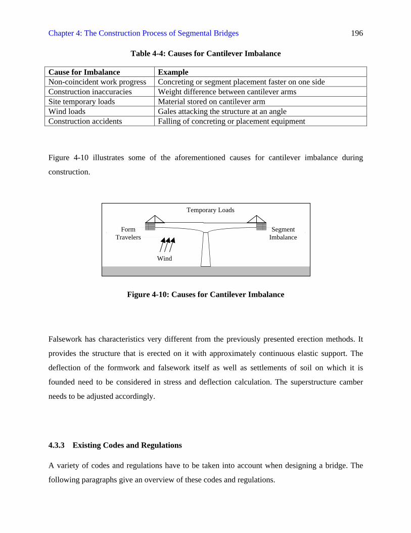
Chapter 4: The Construction Process of Segmental Bridges 196
Table 4-4: Causes for Cantilever Imbalance
Cause for Imbalance ExampleNon-coincident work progress Concreting or segment placement faster on one sideConstruction inaccuracies Weight difference between cantilever armsSite temporary loads Material stored on cantilever armWind loads Gales attacking the structure at an angleConstruction accidents Falling of concreting or placement equipment
Figure 4-10 illustrates some of the aforementioned causes for cantilever imbalance during
construction.
Figure 4-10: Causes for Cantilever Imbalance
Falsework has characteristics very different from the previously presented erection methods. It
provides the structure that is erected on it with approximately continuous elastic support. The
deflection of the formwork and falsework itself as well as settlements of soil on which it is
founded need to be considered in stress and deflection calculation. The superstructure camber
needs to be adjusted accordingly.
4.3.3 Existing Codes and Regulations
A variety of codes and regulations have to be taken into account when designing a bridge. The
following paragraphs give an overview of these codes and regulations.
Wind
Temporary Loads
FormTravelers
SegmentImbalance
Chapter 4: The Construction Process of Segmental Bridges 197
4.3.3.1 American Concrete Institute
The American Concrete Institute (ACI) issues so-called “Committee Reports, Guides, Standard
Practices, and Commentaries” (ACI 1995, p1) that are developed and updated by expert
committees. Apart from the general building code ACI 318 (ACI 1999), the ACI 343R-95
“Analysis and Design of Reinforced Concrete Bridge Structures” (ACI 1995) is of prime
importance for bridge structures. It covers functional requirements, including even a short section
on bridge aesthetics, economics, and erection, materials, basic considerations for construction
works, load cases, design aspects, characteristics of prestressed and precast concrete, substructure
and superstructure, and reinforcement details. Initial sections on requirements for bridges and
construction considerations provide a brief overview of topics related to this study. ACI 343R-95
also gives reference where applicable to other institutions that issue codes and regulations. ACI
345-82 “Standard Practice for Concrete Highway Bridge Deck Construction” is referenced.
4.3.3.2 American Association of State Highway and Transportation Officials
Another important organization is the American Association of State Highway and
Transportation and Highway Officials (AASHTO). AASHTO issues the “Standard Specifications
for Highway Bridges” (AASHTO 1996) and “Guide Specifications for Design and Construction
of Segmental Concrete Bridges” (AASHTO 1998b), along with other manual on construction
practices and specifications for bridge and highway projects (AASHTO 1980), (AASHTO 1985).
Furthermore, AASHTO provides engineers with detailed information on sampling and testing of
materials and their properties for use in transportation projects (AASHTO 1998a). Concrete and
its ingredients, structural steel, steel bolts, metal alloys, reinforcement bars, soil, and timber are
amongst the materials covered. In addition to these topics, testing equipment and procedures are
also described in the comprehensive volume.
In particular, the “Guide Specifications for Design and Construction of Segmental Concrete
Bridges” (AASHTO 1998b) have been developed with respect to the growing number of
segmental bridges to provide information to bridge engineers. The very first section of this guide
(AASHTO 1998b, p6) states that normally “the provisions of the Sixteenth Edition of the
Chapter 4: The Construction Process of Segmental Bridges 198
AASHTO Standard Specifications for Highway Bridges (AASHTO 1996) are intended to apply
to the design of segmental concrete bridges.”
These “Guide Specifications for Design and Construction of Segmental Concrete Bridges”
provide information specifically devised for segmental bridge construction. The manual
comprises two main divisions, dealing with design specifications and with construction
specifications.
Section headings of Division I—Design Specifications include general requirements and
materials, analysis, design, detailing, substructure design, and special provisions for bridge types,
specifications, contract drawings, and alternate construction methods (AASHTO 1998b). In
particular, the subsections under these sections briefly deal with analytical methods, provide
loads and applicable load factors, deal with seismic design, provide information on stresses,
prestress losses, flexural strength, shear and torsion, fatigue stress limits, and deal with the
specifics of anchorage zones. Furthermore, constructive details, such as ducts, couplers, concrete
cover and reinforcement spacing, bearings, expansion joints, and cross-sectional dimensions for
box girders are covered.
Subsection headings of Division II—Construction Specifications include a variety of materials,
such as concrete, mild reinforcement and post-tensioning materials, and guidelines on
construction procedures that are specific to the various methods of segmental bridge
construction, e.g. installation, stressing of post-tensioning tendons and grouting of their ducts,
application of epoxy as a joint sealant, geometry control, shop drawings, bearings, construction
tolerances, and repair of minor defects. The last subsections deal with cast-in-place segmental
construction, precast segmental construction, and incremental launching individually (AASHTO
1998b).
The AASHTO Standard Specifications for Highway Bridges (AASHTO 1996) is a very
comprehensive compilation that provides information for a wide range of issues pertaining to
design of construction of all kinds of highway bridges. The two main divisions, titled design and
construction, respectively, deal with structural systems of bridges, materials and their properties
and testing as well as with details, such as prestressing tendons and anchorages, bearings, joints,
Chapter 4: The Construction Process of Segmental Bridges 199
bridge decks, retaining walls, and railings (AASHTO 1996). Seismic design is covered in a
separate section.
In particular, the AASHTO Standard Specifications for Highway Bridges provide information on
the following actions that may affect the structure: Dead load, live load, impact or dynamic effect
of the live load, wind loads, other forces, such as longitudinal forces, centrifugal force, thermal
forces, earth pressure, buoyancy, shrinkage stresses, rib shortening, erection stresses, ice and
current pressure, and earthquake stresses (AASHTO 1996, p19). However, no reference is given
to erection stages in this context. Section 8.15.3 of Division II—Construction is dealing with
construction loads and states the following (AASHTO 1996, p493):
“Light materials and equipment may be carried on bridge decks only after theconcrete has been in place at least 24 hours, providing curing is not interferedwith and the surface texture is not damaged. Vehicles needed for constructionactivities and weighing between 1,000 and 4,000 pounds [0.454 and 1.814 metrictons], and comparable materials and equipment loads, will be allowed on anyspan only after the last placed deck has attained a compressive strength of at least2,400 pounds per square inch [16.55 N/mm2]. Loads in excess of the above shallnot be carried on bridge decks until the deck concrete has reached its specifiedstrength. In addition, for post-tensioned structures, vehicles weighing over 4,500pounds [2.041 metric tons], and comparable materials and equipment loads, willnot be allowed on any span until the prestressing steel for that span has beentensioned.”
Finally, the provisions of the AASHTO Standard Specifications for Highway Bridges give actual
information on how to treat erection methods (AASHTO 1996, p493):
“Otherwise, loads imposed on existing, new or partially completed portions ofstructures due to construction operations shall not exceed the load-carryingcapacity of the structure, or portion of the structure, as determined by the LoadFactor Design methods of AASHTO using Load Group IB. The compressivestrength of concrete (f’c) to be used in computing the load-carrying capacity shallbe the smaller of the actual compressive strength at the time of loading or thespecified compressive strength of the concrete.”
Table 3.22.1A of Division I—Design provides coefficients for different combinations of loads,
including the aforementioned Load Group IB for both Load Factor Design and Service Load. The
following Table 4-5 gives the values of the aforementioned table particularly applicable for
construction loads, i.e. Load Group IB within Load Factor Design (AASHTO 1996, pp30f):
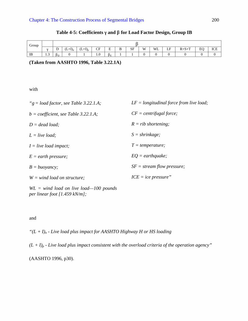
Chapter 4: The Construction Process of Segmental Bridges 200
Table 4-5: Coefficients γγ and ββ for Load Factor Design, Group IB
βGroupγ D (L+I)n (L+I)p CF E B SF W WL LF R+S+T EQ ICE
IB 1.3 βD 0 1 1.0 βE 1 1 0 0 0 0 0 0
(Taken from AASHTO 1996, Table 3.22.1A)
with
“γ = load factor, see Table 3.22.1.A;
β = coefficient, see Table 3.22.1.A;
D = dead load;
L = live load;
I = live load impact;
E = earth pressure;
B = buoyancy;
W = wind load on structure;
WL = wind load on live load—100 poundsper linear foot [1.459 kN/m];
LF = longitudinal force from live load;
CF = centrifugal force;
R = rib shortening;
S = shrinkage;
T = temperature;
EQ = earthquake;
SF = stream flow pressure;
ICE = ice pressure”
and
“(L + I)n - Live load plus impact for AASHTO Highway H or HS loading
(L + I)p - Live load plus impact consistent with the overload criteria of the operation agency”
(AASHTO 1996, p30).

Chapter 4: The Construction Process of Segmental Bridges 201
Values for the coefficient for earth pressure βE and the coefficient for dead load βD are provided
in the explanations for Table 3.22.1A. Applicable in the case of members in bridge
superstructures would be βE = 0.5 to 1.3 for different cases of earth pressure and βD = 0.75 to 1.0
“For Column Design” or “βD = 1.0 for flexural and tension members”, respectively (AASHTO
1996, p30).
4.3.3.3 American Society for Testing and Materials
The American Society for Testing and Materials (ASTM) also provides comprehensive
specifications on the manifold aspects of materials testing and gives information on properties of
construction materials, e.g. structural steel, reinforcement bars, and concrete and its ingredients
(ASTM 1996).
4.3.3.4 American Welding Society
The American Welding Society (AWS) provides standards for welding of reinforcing bars,
including information on material characteristics, limit stresses, splice details, quality of
workmanship and inspections, and on the different welding techniques (AWS 1975).
4.3.3.5 Concrete Reinforcing Steel Institute
The Concrete Reinforcing Steel Institute (CRSI 1996) gives detailed information on formwork
systems as well as reinforcement bars and welded wire fabric.
Chapter 4: The Construction Process of Segmental Bridges 202
4.3.3.6 Other Institutions
Other notable institutions are the American Institute of Steel Construction (AISC), the
Prestressed Concrete Institute (PCI), the Portland Cement Association (PCA), and the
Transportation Research Board (TRB) of the National Research Council. They publish manuals
and professional journals on concrete and steel technology that present state-of-the-art design
methods and construction projects.
4.3.3.7 Federal Highway Administration
The Federal Highway Administration (FHWA) is a branch of the U.S. Department of
Transportation and is located in Washington, D.C. with so-called field offices all over the nation.
It is fulfilling its mission of creating and maintaining high-quality transportation systems in
several ways. The following brief summary is based on information provided by the Federal
Highway Administration on its site on the World Wide Web (FHWA 1999).
A main area of FHWA activities is provision of technical expertise for design, construction, and
maintenance of transportation projects through close cooperation with regional and local
authorities. To support this work research projects are undertaken, e.g. in advanced technologies
for supervision of traffic. Secondly, the FHWA supervises federal funding for transportation
projects and sets up regulations for such projects. In case of natural disasters and other major
incidents in the transportation systems the FHWA assists with investigation and repair works.
The FHWA also develops regulations and guidelines for construction projects that are related to
public transportation.
Apart from regulatory work the FHWA is also active in the field of training and educating
professionals in transportation issues, such as safety, economy, and protection of the
environment. An example for training is seismic bridge design, which the FHWA conducted to
improve safety of bridge structure in case of earthquakes. The very large variety of programs that
the FHWA sponsors shows the involvement of this institution in bridge construction.
Chapter 4: The Construction Process of Segmental Bridges 203
4.3.3.8 Owner Specifications
Finally, the owner of a construction project usually provides detailed information in form of
plans (VDOT 1997b) and specifications (VDOT 1998) that comprise the documents for
advertisement of bidding. For bridge projects the owners will predominantly be the State
Departments of Transportation, e.g. the Commonwealth of Virginia Department of
Transportation (VDOT), which issues “Metric Road and Bridge Specifications” (VDOT 1997c).
These include two major parts, the General Provisions that provide general rules for contractual
issues and the Specifications, which deal with different topics such as materials, roadway
construction, bridges and other structures, incidental construction works, roadside development,
and traffic control devices.