Embed Size (px)
Citation preview
See Through Walls with Wi-Fi!Fadel Adib and Dina Katabi
Massachusetts Institute of Technology{fadel,dk}@mit.edu
ABSTRACTWi-Fi signals are typically information carriers between a trans-
mitter and a receiver. In this paper, we show that Wi-Fi can alsoextend our senses, enabling us to see moving objects through wallsand behind closed doors. In particular, we can use such signals toidentify the number of people in a closed room and their relativelocations. We can also identify simple gestures made behind a wall,and combine a sequence of gestures to communicate messages toa wireless receiver without carrying any transmitting device. Thepaper introduces two main innovations. First, it shows how one canuse MIMO interference nulling to eliminate reflections off staticobjects and focus the receiver on a moving target. Second, it showshow one can track a human by treating the motion of a human bodyas an antenna array and tracking the resulting RF beam. We demon-strate the validity of our design by building it into USRP softwareradios and testing it in office buildings.
Categories and Subject Descriptors C.2.2 [ComputerSystems Organization]: Computer-Communications Networks.H.5.2 [Information Interfaces and Presentation]: User Inter-faces - Input devices and strategies.Keywords Seeing Through Walls, Wireless, MIMO, Gesture-Based User Interface
1. INTRODUCTIONCan Wi-Fi signals enable us to see through walls? For many
years humans have fantasized about X-ray vision and played withthe concept in comic books and sci-fi movies. This paper exploresthe potential of using Wi-Fi signals and recent advances in MIMOcommunications to build a device that can capture the motion ofhumans behind a wall and in closed rooms. Law enforcement per-sonnel can use the device to avoid walking into an ambush, andminimize casualties in standoffs and hostage situations. Emergencyresponders can use it to see through rubble and collapsed structures.Ordinary users can leverage the device for gaming, intrusion detec-tion, privacy-enhanced monitoring of children and elderly, or per-sonal security when stepping into dark alleys and unknown places.
The concept underlying seeing through opaque obstacles is sim-ilar to radar and sonar imaging. Specifically, when faced with anon-metallic wall, a fraction of the RF signal would traverse thewall, reflect off objects and humans, and come back imprinted witha signature of what is inside a closed room. By capturing these re-flections, we can image objects behind a wall. Building a devicethat can capture such reflections, however, is difficult because the
Permission to make digital or hard copies of all or part of this work for personal orclassroom use is granted without fee provided that copies are not made or distributedfor profit or commercial advantage and that copies bear this notice and the full citationon the first page. Copyrights for components of this work owned by others than theauthor(s) must be honored. Abstracting with credit is permitted. To copy otherwise, orrepublish, to post on servers or to redistribute to lists, requires prior specific permissionand/or a fee. Request permissions from [email protected]’13, August 12–16, 2013, Hong Kong, China.Copyright is held by the owner/author(s). Publication rights licensed to ACM.Copyright 2013 ACM 978-1-4503-2056-6/13/08 ...$15.00.
signal power after traversing the wall twice (in and out of the room)is reduced by three to five orders of magnitude [11]. Even morechallenging are the reflections from the wall itself, which are muchstronger than the reflections from objects inside the room [11, 27].Reflections off the wall overwhelm the receiver’s analog to digitalconverter (ADC), preventing it from registering the minute varia-tions due to reflections from objects behind the wall. This behavioris called the “Flash Effect" since it is analogous to how a mirror infront of a camera reflects the camera’s flash and prevents it fromcapturing objects in the scene.
So how can one overcome these difficulties? The radar com-munity has been investigating these issues, and has recently in-troduced a few ultra-wideband systems that can detect humansmoving behind a wall, and show them as blobs moving in a dimbackground [27, 41] (see the video at [6] for a reference). Today’sstate-of-the-art system requires 2 GHz of bandwidth, a large powersource, and an 8-foot long antenna array (2.4 meters) [12, 27].Apart from the bulkiness of the device, blasting power in such awide spectrum is infeasible for entities other than the military. Therequirement for multi-GHz transmission is at the heart of how thesesystems work: they separate reflections off the wall from reflec-tions from the objects behind the wall based on their arrival time,and hence need to identify sub-nanosecond delays (i.e., multi-GHzbandwidth) to filter the flash effect.1 To address these limitations,an initial attempt was made in 2012 to use Wi-Fi to see through awall [13]. However, to mitigate the flash effect, this past proposalneeds to install an additional receiver behind the wall, and connectthe receivers behind and in front of the wall to a joint clock viawires [13].
The objective of this paper is to enable a see-through-wall tech-nology that is low-bandwidth, low-power, compact, and accessibleto non-military entities. To this end, the paper introduces Wi-Vi,2 asee-through-wall device that employs Wi-Fi signals in the 2.4 GHzISM band. Wi-Vi limits itself to a 20 MHz-wide Wi-Fi channel,and avoids ultra-wideband solutions used today to address the flasheffect. It also disposes of the large antenna array, typical in pastsystems, and uses instead a smaller 3-antenna MIMO radio.
So, how does Wi-Vi eliminate the flash effect without using GHzof bandwidth? We observe that we can adapt recent advances inMIMO communications to through-wall imaging. In MIMO, mul-tiple antenna systems can encode their transmissions so that the sig-nal is nulled (i.e., sums up to zero) at a particular receive antenna.MIMO systems use this capability to eliminate interference to un-wanted receivers. In contrast, we use nulling to eliminate reflectionsfrom static objects, including the wall. Specifically, a Wi-Vi devicehas two transmit antennas and a single receive antenna. Wi-Vi op-erates in two stages. In the first stage, it measures the channels fromeach of its two transmit antennas to its receive antenna. In stage 2,the two transmit antennas use the channel measurements from stage1 to null the signal at the receive antenna. Since wireless signals (in-cluding reflections) combine linearly over the medium, only reflec-
1Filtering is done in the analog domain before the signal reaches the ADC.2Wi-Vi stands for Wi-Fi Vision.
tions off objects that move between the two stages are captured instage 2. Reflections off static objects, including the wall, are nulledin this stage. In §4, we refine this basic idea by introducing iterativenulling, which allows us to eliminate residual flash and the weakerreflections from static objects behind the wall.
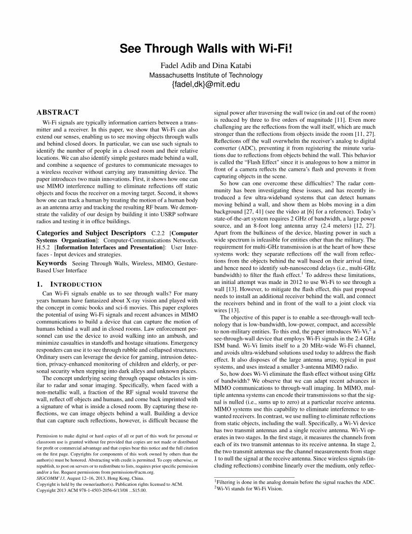
Second, how does Wi-Vi track moving objects without an an-tenna array? To address this challenge, we borrow a techniquecalled inverse synthetic aperture radar (ISAR), which has been usedfor mapping the surfaces of the Earth and other planets. ISAR usesthe movement of the target to emulate an antenna array. As shown inFig. 1, a device using an antenna array would capture a target fromspatially spaced antennas and process this information to identifythe direction of the target with respect to the array (i.e., !). In con-trast, in ISAR, there is only one receive antenna; hence, at any pointin time, we capture a single measurement. Nevertheless, since thetarget is moving, consecutive measurements in time emulate an in-verse antenna array – i.e., it is as if the moving human is imagingthe Wi-Vi device. By processing such consecutive measurementsusing standard antenna array beam steering, Wi-Vi can identify thespatial direction of the human. In §5.2, we extend this method tomultiple moving targets.
Additionally, Wi-Vi leverages its ability to track motion to en-able a through-wall gesture-based communication channel. Specif-ically, a human can communicate messages to a Wi-Vi receiver viagestures without carrying any wireless device. We have picked twosimple body gestures to refer to “0” and “1” bits. A human behinda wall may use a short sequence of these gestures to send a mes-sage to Wi-Vi. After applying a matched filter, the message signallooks similar to standard BPSK encoding (a positive signal for a“1” bit, and a negative signal for a “0” bit) and can be decoded byconsidering the sign of the signal. The system enables law enforce-ment personnel to communicate with their team across a wall, evenif their communication devices are confiscated.
We built a prototype of Wi-Vi using USRP N210 radios and eval-uated it in two office buildings. Our results are as follows:• Wi-Vi can detect objects and humans moving behind opaque
structural obstructions. This applies to 8!! concrete walls, 6!! hol-low walls, and 1.75!! solid wooden doors.
• A Wi-Vi device pointed at a closed room with 6!! hollow wallssupported by steel frames can distinguish between 0, 1, 2, and 3moving humans in the room. Computed over 80 trials with 8 hu-man subjects, Wi-Vi achieves an accuracy of 100%, 100%, 85%,and 90% respectively in each of these cases.
• In the same room, and given a single person sending gesture-based messages, Wi-Vi correctly decodes all messages per-formed at distances equal to or smaller than 5 meters. The de-coding accuracy decreases to 75% at distances of 8 meters, andthe device stops detecting gestures beyond 9 meters. For 8 vol-unteers who participated in the experiment, on average, it took aperson 8.8 seconds to send a message of 4 gestures.
• In comparison to the state-of-the-art ultra-wideband see-through-wall radar [27], Wi-Vi is limited in two ways. First, replacing theantenna array by ISAR means that the angular resolution in Wi-Vi depends on the amount of movement. To achieve a narrowbeam the human needs to move by about 4 wavelengths (i.e.,about 50 cm). Second, in contrast to [27], we cannot detect hu-mans behind concrete walls thicker than 8!!. This is due to boththe much lower transmit power from our USRPs and the residualflash power from imperfect nulling. On the other hand, nullingthe flash removes the need for GHz bandwidth. It also removesclutter from all static reflectors, rather than just one wall. This in-cludes other walls in the environments as well as furniture insideand outside the imaged room. To reduce clutter, the empirical re-sults in past work are typically collected using a person-height
��
������������
��������
������������
� ��������������� ��������������
��
(a) Antenna Array (b) ISARFigure 1—A Moving Object as an Antenna Array. In (a), an antennaarray is able to locate an object by steering its beam spatially. In (b), themoving object itself emulates an antenna array; hence, it acts as an inversesynthetic aperture. Wi-Vi leverages this principle in order to beamform thereceived signal in time (rather than in space) and locate the moving object.
standing wall, positioned either outdoors or in large empty in-door spaces [27, 41]. In contrast, our experiments are in stan-dard office buildings with the imaged humans inside closed fully-furnished rooms.
Contributions: In contrast to past work which targets the military,Wi-Vi introduces novel solutions to the see-through-wall problemthat enable non-military entities to use this technology. Specifically,Wi-Vi is the first to introduce interference nulling as a mechanismfor eliminating the flash effect without requiring wideband spec-trum. It is also the first to replace the antenna array at the receiverwith an emulated array based on human motion. The combinationof those techniques enables small cheap devices that operate in theISM band, and can be made accessible to the general public. Fur-ther, Wi-Vi is the first to demonstrate a gesture-based communica-tion channel that operates through walls and does not require thehuman to carry any wireless device.
2. RELATED WORKWi-Vi is related to past work in three major areas:
Through-wall radar. Interest in through-wall imaging has beensurging for about a decade [5]. Earlier work in this domain focusedon simulations [38, 28] and modeling [32, 33]. Recently, there havebeen some implementations tested with moving humans [27, 41,13]. These past systems eliminate the flash effect by isolating thesignal reflected off the wall from signals reflected off objects be-hind the wall. This isolation can be achieved in the time domain,by using very short pulses (less than 1ns) [40, 5] whereby the pulsereflected off the wall arrives earlier in time than that reflected offmoving objects behind it. Alternatively, it may be achieved in thefrequency domain by using a linear frequency chirp [11, 27]. Inthis case, reflections off objects at different distances arrive withdifferent tones. By analog filtering the tone that corresponds to thewall, one may remove the flash effect. These techniques requireultra-wide bandwidths (UWB) of the order of 2 GHz [11, 40]. Sim-ilarly, through-wall imaging products developed by the industry [5,7] hinge on the same radar principles, requiring multiple GHz ofbandwidth and hence are targeted solely at the military.
As a through-wall imaging technology, Wi-Vi differs from allthe above systems in that it requires only few MHz of bandwidthand operates in the same range as Wi-Fi. It overcomes the need forUWB by leveraging MIMO nulling to remove the flash effect.
Researchers have recognized the limitations of UWB systemsand explored the potential of using narrowband radars for through-wall technologies [29, 30]. These systems ignore the flash effectand try to operate in presence of high interference caused by reflec-tions off the wall. They typically rely on detecting the Doppler shift
caused by moving objects behind the wall. However, the flash effectlimits their detection capabilities. Hence, most of these systems aredemonstrated either in simulation [28], or in free space with no ob-struction [21, 23]. The ones demonstrated with an obstruction usea low-attenuation standing wall, and do not work across higher at-tenuation materials such as solid wood or concrete [29, 30]. Wi-Vishares the objectives of these devices; however, it introduces a newapproach for eliminating the flash effect without wideband trans-mission. This enables it to work with concrete walls and solid wooddoors, as well as fully closed rooms.
The only attempt which we are aware of that uses Wi-Fi signalsin order to see through walls was made in 2012 [13]. This systemrequired both the transmitter and a reference receiver to be insidethe imaged room. Furthermore, the reference receiver in the roomhas to be connected to the same clock as the receiver outside theroom. In contrast, Wi-Vi can perform through-wall imaging withoutaccess to any device on the other side of the wall.Gesture-based interfaces. Today, commercial gesture-recognitionsystems – such as the Xbox Kinect [9], Nintendo Wii [4], etc. – canidentify a wide variety of gestures. The academic community hasalso developed systems capable of identifying human gestures ei-ther by employing cameras [24] or by placing sensors on the humanbody [15, 20]. Recent work has also leveraged narrowband signalsin the 2.4 GHz range to identify human activities in line-of-sightusing micro-Doppler signatures [21]. Wi-Vi, however, presents thefirst gesture-based interface that works in non-line-of-sight scenar-ios, and even through a wall, yet does not require the human to carrya wireless device or wear a set of sensors.Infrared and thermal imaging. Similar to Wi-Vi, these technolo-gies extend human vision beyond the visible electromagnetic range,allowing us to detect objects in the dark or in smoke. They operateby capturing infrared or thermal energy reflected off the first ob-stacle in line-of-sight of their sensors. However, cameras based onthese technologies cannot see through walls because they have veryshort wavelengths (few µm to sub-mm) [37], unlike Wi-Vi whichemploys signals whose wavelengths are 12.5 cm.3
3. WI-VI OVERVIEWWi-Vi is a wireless device that captures moving objects behind a
wall. It leverages the ubiquity of Wi-Fi chipsets to make through-wall imaging relatively low-power, low-cost, low-bandwidth, andaccessible to average users. To this end, Wi-Vi uses Wi-Fi OFDMsignals in the ISM band (at 2.4 GHz) and typical Wi-Fi hardware.
Wi-Vi is essentially a 3-antenna MIMO device: two of the anten-nas are used for transmitting and one is used for receiving. It alsoemploys directional antennas to focus the energy toward the wallor room of interest.4 Its design incorporates two main components:1) the first component eliminates the flash reflected off the wall byperforming MIMO nulling; 2) the second component tracks a mov-ing object by treating the object itself as an antenna array using atechnique called inverse SAR.
Wi-Vi can be used in one of two modes, depending on the user’schoice. In mode 1, it can be used to image moving objects behind awall and track them. In mode 2, on the other hand, Wi-Vi functionsas a gesture-based interface from behind a wall that enables humansto compose messages and send them to the Wi-Vi receiver.
In sections 4-6, we describe Wi-Vi’s operation in detail.
3The longer the wavelength of an electromagnetic wave is, the lower itsattenuation is [35]. Infrared and thermal imaging devices employ signalswhose wavelengths are very close to visible light; hence, they do not pene-trate building materials such as wood or concrete.4Directional antennas have a form factor on the order of the wavelength. AtWi-Fi frequencies, this corresponds to approximately 12 cm.
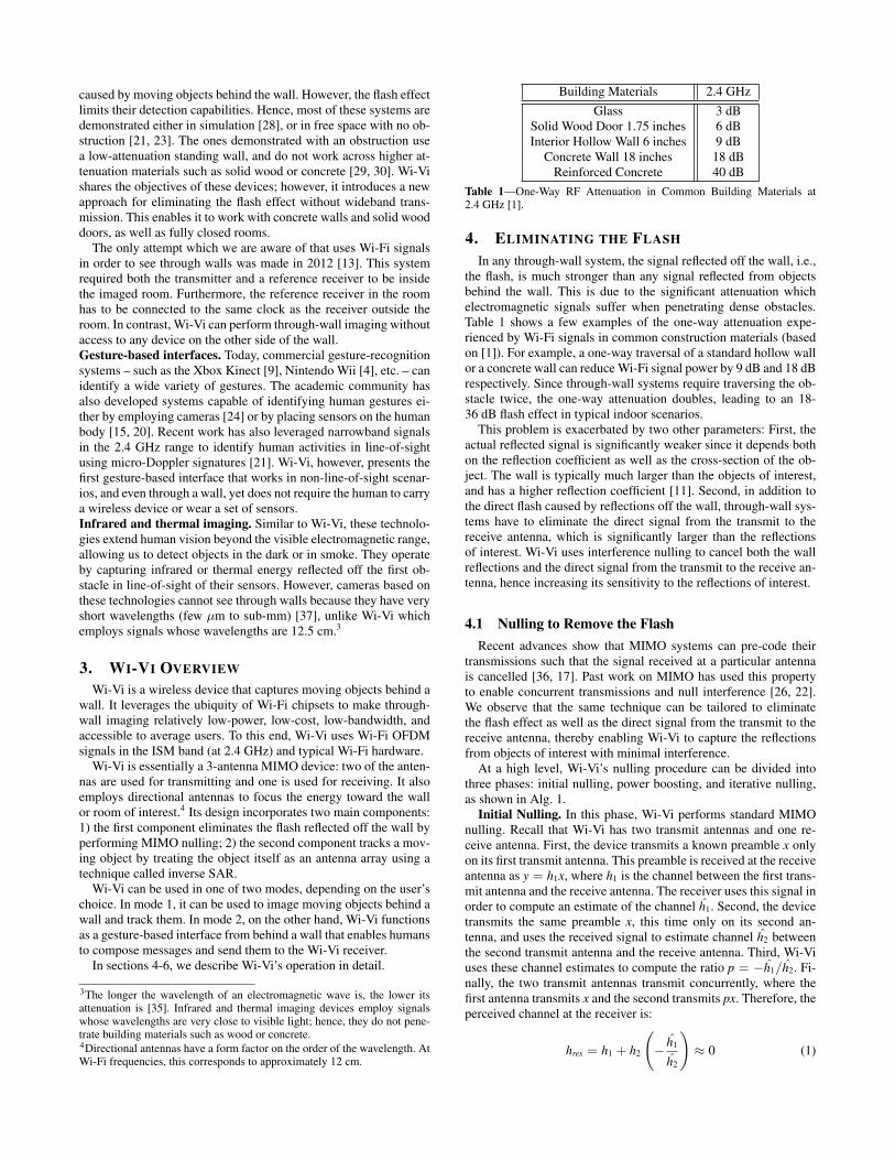
Building Materials 2.4 GHzGlass 3 dB
Solid Wood Door 1.75 inches 6 dBInterior Hollow Wall 6 inches 9 dB
Concrete Wall 18 inches 18 dBReinforced Concrete 40 dB
Table 1—One-Way RF Attenuation in Common Building Materials at2.4 GHz [1].
4. ELIMINATING THE FLASHIn any through-wall system, the signal reflected off the wall, i.e.,
the flash, is much stronger than any signal reflected from objectsbehind the wall. This is due to the significant attenuation whichelectromagnetic signals suffer when penetrating dense obstacles.Table 1 shows a few examples of the one-way attenuation expe-rienced by Wi-Fi signals in common construction materials (basedon [1]). For example, a one-way traversal of a standard hollow wallor a concrete wall can reduce Wi-Fi signal power by 9 dB and 18 dBrespectively. Since through-wall systems require traversing the ob-stacle twice, the one-way attenuation doubles, leading to an 18-36 dB flash effect in typical indoor scenarios.
This problem is exacerbated by two other parameters: First, theactual reflected signal is significantly weaker since it depends bothon the reflection coefficient as well as the cross-section of the ob-ject. The wall is typically much larger than the objects of interest,and has a higher reflection coefficient [11]. Second, in addition tothe direct flash caused by reflections off the wall, through-wall sys-tems have to eliminate the direct signal from the transmit to thereceive antenna, which is significantly larger than the reflectionsof interest. Wi-Vi uses interference nulling to cancel both the wallreflections and the direct signal from the transmit to the receive an-tenna, hence increasing its sensitivity to the reflections of interest.
4.1 Nulling to Remove the FlashRecent advances show that MIMO systems can pre-code their
transmissions such that the signal received at a particular antennais cancelled [36, 17]. Past work on MIMO has used this propertyto enable concurrent transmissions and null interference [26, 22].We observe that the same technique can be tailored to eliminatethe flash effect as well as the direct signal from the transmit to thereceive antenna, thereby enabling Wi-Vi to capture the reflectionsfrom objects of interest with minimal interference.
At a high level, Wi-Vi’s nulling procedure can be divided intothree phases: initial nulling, power boosting, and iterative nulling,as shown in Alg. 1.
Initial Nulling. In this phase, Wi-Vi performs standard MIMOnulling. Recall that Wi-Vi has two transmit antennas and one re-ceive antenna. First, the device transmits a known preamble x onlyon its first transmit antenna. This preamble is received at the receiveantenna as y = h1x, where h1 is the channel between the first trans-mit antenna and the receive antenna. The receiver uses this signal inorder to compute an estimate of the channel h1. Second, the devicetransmits the same preamble x, this time only on its second an-tenna, and uses the received signal to estimate channel h2 betweenthe second transmit antenna and the receive antenna. Third, Wi-Viuses these channel estimates to compute the ratio p = !h1/h2. Fi-nally, the two transmit antennas transmit concurrently, where thefirst antenna transmits x and the second transmits px. Therefore, theperceived channel at the receiver is:
hres = h1 + h2
!! h1
h2
"" 0 (1)
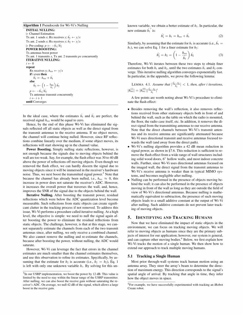
Algorithm 1 Pseudocode for Wi-Vi’s NullingINITIAL NULLING:! Channel EstimationTx ant. 1 sends x; Rx receives y; h1 ! y/xTx ant. 2 sends x; Rx receives y; h2 ! y/x! Pre-coding: p! "h1/h2POWER BOOSTING:Tx antennas boost powerTx ant. 1 transmits x, Tx ant. 2 transmits px concurrentlyITERATIVE NULLING:i! 0repeat
Rx receives y; hres ! y/xif i even then
h1 ! hres + h1else
h2 !!
1" hresh1
"h2
p! "h1/h2Tx antennas transmit concurrentlyi! i + 1
until Converges
In the ideal case, where the estimates h1 and h2 are perfect, thereceived signal hres would be equal to zero.
Hence, by the end of this phase Wi-Vi has eliminated the sig-nals reflected off all static objects as well as the direct signal fromthe transmit antennas to the receive antenna. If no object moves,the channel will continue being nulled. However, since RF reflec-tions combine linearly over the medium, if some object moves, itsreflections will start showing up in the channel value.
Power Boosting. Simply nulling static reflections, however, isnot enough because the signals due to moving objects behind thewall are too weak. Say, for example, the flash effect was 30 to 40 dBabove the power of reflections off moving objects. Even though weremoved the flash effect, we can hardly discern the signal due tomoving objects since it will be immersed in the receiver’s hardwarenoise. Thus, we next boost the transmitted signal power.5 Note thatbecause the channel has already been nulled, i.e., hres " 0, thisincrease in power does not saturate the receiver’s ADC. However,it increases the overall power that traverses the wall, and, hence,improves the SNR of the signal due to the objects behind the wall.
Iterative Nulling. After boosting the transmit power, residualreflections which were below the ADC quantization level becomemeasurable. Such reflections from static objects can create signifi-cant clutter in the tracking process if not removed. To address thisissue, Wi-Vi performs a procedure called iterative nulling. At a highlevel, the objective is simple: we need to null the signal again af-ter boosting the power to eliminate the residual reflections fromstatic objects. The challenge, however, is that at this stage, we can-not separately estimate the channels from each of the two transmitantennas since, after nulling, we only receive a combined channel.We also cannot remove the nulling and re-estimate the channels,because after boosting the power, without nulling, the ADC wouldsaturate.
However, Wi-Vi can leverage the fact that errors in the channelestimates are much smaller than the channel estimates themselves,and use this observation to refine its estimates. Specifically, by as-suming that the estimate for h2 is accurate (i.e., h2 = h2), Eq. 1is left with only one unknown variable h1. By solving for this un-
5In our USRP implementation, we boost the power by 12 dB. This value islimited by the need to stay within the linear range of the USRP transmitter.After nulling, we can also boost the receive gain without saturating the re-ceiver’s ADC. On average, we null 42 dB of the signal, which allows a largeboost in the receive gain.
known variable, we obtain a better estimate of h1. In particular, thenew estimate h1
!is:
h!1 = h1 = hres + h1 (2)
Similarly, by assuming that the estimate for h1 is accurate (i.e., h1 =h1), we can solve Eq. 1 for a finer estimate for h2:
h!2 = h2 =
#1 ! hres
h1
$h2 (3)
Therefore, Wi-Vi iterates between these two steps to obtain finerestimates for both h1 and h2, until the two estimates h1 and h2 con-verge. This iterative nulling algorithm converges exponentially fast.In particular, in the appendix, we prove the following lemma:
LEMMA 4.1. Assume that | h2"h2h2
| < 1, then, after i iterations,
|h(i)res | = |h(0)
res || h2"h2h2
|i
A few points are worth noting about Wi-Vi’s procedure to elimi-nate the flash effect:
• Besides removing the wall’s reflection, it also removes reflec-tions received from other stationary objects both in front of andbehind the wall, such as the table on which the radio is mounted,the floor, the radio case itself, etc. In addition, it removes the di-rect signal from the transmitting antennas to our receive antenna.Note that the direct channels between Wi-Vi’s transmit anten-nas and its receive antenna are significantly attenuated becauseWi-Vi uses directional transmit and receive antennas focused to-wards the wall (and away from the direct path).
• Wi-Vi’s nulling algorithm provides a 42 dB mean reduction insignal power, as shown in §7.6. This reduction is sufficient to re-move the flash effect from a wide range of wall structures includ-ing solid wood doors, 6” hollow walls, and most indoor concretewalls. Further, since Wi-Vi uses directional antennas focused onthe imaged wall, the direct signal from the transmit antennas toWi-Vi’s receive antenna is weaker than in typical MIMO sys-tems, and becomes negligible after nulling.
• Nulling can be performed in the presence of objects moving be-hind the wall; it can also be performed in the presence of objectsmoving in front of the wall as long as they are outside the field ofview of Wi-Vi’s directional antennas. Because nulling is mathe-matically equivalent to subtraction, the presence of such movingobjects leads to a small additive constant at the output of Wi-Viafter nulling. Such additive constants do not prevent later track-ing of moving objects.
5. IDENTIFYING AND TRACKING HUMANSNow that we have eliminated the impact of static objects in the
environment, we can focus on tracking moving objects. We willrefer to moving objects as humans since they are the primary sub-jects of interest for our application; however, our system is general,and can capture other moving bodies.6 Below, we first explain howWi-Vi tracks the motion of a single human. We then show how toextend our approach to track multiple moving humans.
5.1 Tracking a Single HumanMost prior through-wall systems track human motion using an
antenna array. They steer the array’s beam to determine the direc-tion of maximum energy. This direction corresponds to the signal’sspatial angle of arrival. By tracking that angle in time, they inferhow the object moves in space.6For example, we have successfully experimented with tracking an iRobotCreate robot.
����� ����� ����� ������ ��������
��������������
����������������
��������������
Figure 2—Time samples as Antenna Arrays. Wi-Vi groups consecutivetime samples into overlapping windows of size w, then treats each windowh[n] . . . h[n + w] as an antenna array. This allows it to track the direction ofa moving object with respect to the receiver.
Wi-Vi, however, avoids using an antenna array for two reasons:First, in order to obtain a narrow beam and hence achieve a goodresolution, one needs a large antenna array with many antenna ele-ments. This would result in a bulky and expensive device. Second,since Wi-Vi eliminates the flash effect using MIMO nulling, addingmultiple receive antennas would require nulling the signal at eachof them. This would require adding more transmit antennas, thusmaking the device even bulkier and more expensive.
To capture the benefits of an antenna array while avoiding itsdrawbacks, Wi-Vi leverages a technique called inverse syntheticaperture radar (ISAR). ISAR exploits the movement of the tar-get to emulate an antenna array. Existing systems which use an-tenna arrays capture the signal reflected off a target from spatiallyspaced antennas and processes this information to identify the di-rection of the target with respect to the array. In contrast, in ISAR,there is only one receive antenna; hence, at any point in time,the receiver captures a single measurement. However, as the targetmoves, he/she samples the received signal at successive locationsin space, as if we had a receive antenna at each of these points. Fur-thermore, because of channel reciprocity, successive time samplesreceived by Wi-Vi correspond to successive spatial locations of themoving target. Hence, Wi-Vi effectively receives in time what anantenna array would receive in space. By treating consecutive timesamples as spatial samples, Wi-Vi can emulate an antenna array anduse it to track motion behind the wall.
In what follows, we formalize the above discussion. Let y[n] bethe signal sample received by Wi-Vi at a discrete time point n. De-fine the spatial angle ! as the angle between the line connecting thehuman to Wi-Vi and the normal to the motion, as shown in Fig. 1(b).Note that the sign of ! is positive when the vector from the humanto Wi-Vi and the vector of the motion are in the same direction, andnegative when these two vectors are in opposite directions.
We are interested in computing A[!, n], a function that measuresthe signal along the spatial direction ! at time n. To compute thisvalue, Wi-Vi first processes the received samples to remove the ef-fect of the transmitted signal, and obtain the channel as a func-tion of time, i.e., h[n] = y[n]/x[n]. To emulate an antenna arrayof size w, Wi-Vi considers w consecutive channel measurementsh[n] . . . h[n + w], as shown in Fig. 2. Wi-Vi then computes A[!, n]by applying standard antenna array equations [34] as follows:
A[!, n] =w%
i=1
h[n + i]ej 2!" i! sin ! , (4)
where " is the wavelength, and ! is the spatial separation betweensuccessive antennas in the array.7 At any point in time n, the valueof ! that produces the highest value in A[!, n] will correspond to thedirection along which the object is moving.
To compute A[!, n] from the above equation, we need to estimate!, the antenna spacing in the emulated array. Since human motionemulates the antennas in the array, ! = vT , where T is Wi-Vi’s
7! is twice the one-way separation to account for the round-trip time.
������������
�n=0�n=0�n=3�n=3
�n=4�n=
�n=5�=5n=
4
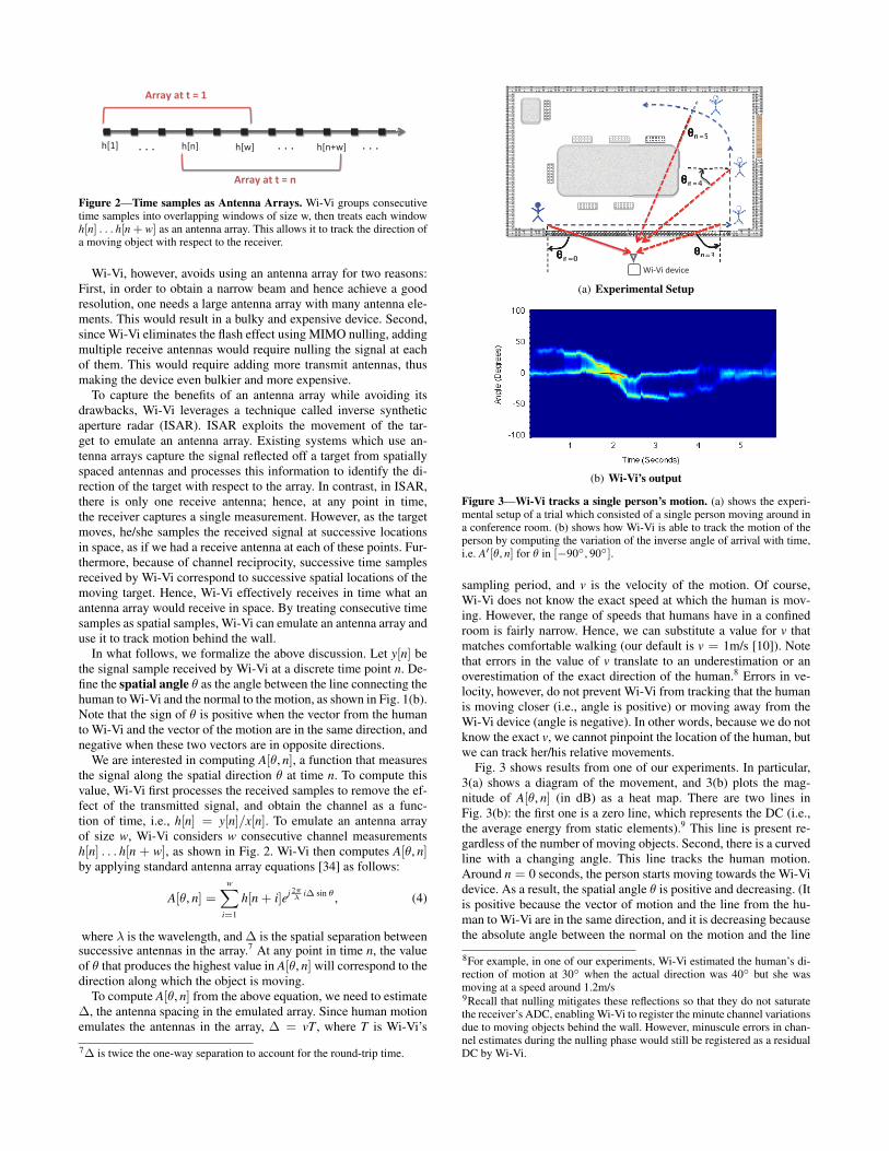
(a) Experimental Setup
(b) Wi-Vi’s output
Figure 3—Wi-Vi tracks a single person’s motion. (a) shows the experi-mental setup of a trial which consisted of a single person moving around ina conference room. (b) shows how Wi-Vi is able to track the motion of theperson by computing the variation of the inverse angle of arrival with time,i.e. A![!, n] for ! in ["90#, 90#].
sampling period, and v is the velocity of the motion. Of course,Wi-Vi does not know the exact speed at which the human is mov-ing. However, the range of speeds that humans have in a confinedroom is fairly narrow. Hence, we can substitute a value for v thatmatches comfortable walking (our default is v = 1m/s [10]). Notethat errors in the value of v translate to an underestimation or anoverestimation of the exact direction of the human.8 Errors in ve-locity, however, do not prevent Wi-Vi from tracking that the humanis moving closer (i.e., angle is positive) or moving away from theWi-Vi device (angle is negative). In other words, because we do notknow the exact v, we cannot pinpoint the location of the human, butwe can track her/his relative movements.
Fig. 3 shows results from one of our experiments. In particular,3(a) shows a diagram of the movement, and 3(b) plots the mag-nitude of A[!, n] (in dB) as a heat map. There are two lines inFig. 3(b): the first one is a zero line, which represents the DC (i.e.,the average energy from static elements).9 This line is present re-gardless of the number of moving objects. Second, there is a curvedline with a changing angle. This line tracks the human motion.Around n = 0 seconds, the person starts moving towards the Wi-Videvice. As a result, the spatial angle ! is positive and decreasing. (Itis positive because the vector of motion and the line from the hu-man to Wi-Vi are in the same direction, and it is decreasing becausethe absolute angle between the normal on the motion and the line
8For example, in one of our experiments, Wi-Vi estimated the human’s di-rection of motion at 30# when the actual direction was 40# but she wasmoving at a speed around 1.2m/s9Recall that nulling mitigates these reflections so that they do not saturatethe receiver’s ADC, enabling Wi-Vi to register the minute channel variationsdue to moving objects behind the wall. However, minuscule errors in chan-nel estimates during the nulling phase would still be registered as a residualDC by Wi-Vi.
from the human to Wi-Vi is getting smaller.) Around n = 1.8s, theperson crosses in front of the Wi-Vi device, at which time his an-gle becomes zero. From n = 1.8s to n = 3s, the person is movingaway from Wi-Vi, and hence, his angle is negative. But the abso-lute value of the angle is decreasing. At n = 3, the person turns andstarts moving inward, causing the angle to go back toward zero,but the signal becomes weaker as he is now relatively far from theWi-Vi receiver.10
5.2 Tracking Multiple HumansIn this section, we show how Wi-Vi extends its tracking proce-
dure to multiple humans. Our previous discussion about using hu-man motion to emulate an antenna array still holds. However, eachhuman will emulate a separate antenna array. Since Wi-Vi has asingle antenna, the received signal will be a superposition of theantenna arrays of the moving humans. In particular, instead of hav-ing one curved line as in Fig. 3(b), at any time, there will be asmany curved lines as moving humans at that point in time.
However, with multiple humans, the noise increases signifi-cantly. On one hand, each human is not just one object because ofdifferent body parts moving in a loosely coupled way. On the otherhand, the signal reflected off all of these humans is correlated intime, since they all reflect the transmitted signal. The lack of inde-pendence between the reflected signals is important. For example,the reflections of two humans may combine systematically to dimeach other over some period of time.
The problem of disentangling correlated super-imposed signalsis well studied in signal processing. The basic approach for process-ing such signals relies on the smoothed MUSIC algorithm [31, 39].Similar to the standard antenna array processing in Eq. 4, smoothedMUSIC computes the power received along a particular direction,which we call A![!, n] because it estimates the same function inEq. 4 but in manner more resilient to noise and correlated sig-nals [34].
For a given antenna array h = (h[n], . . . , h[n + w]) of size w,MUSIC first computes the w # w correlation matrix R[n]:
R[n] = E[hhH], (5)
where H refers to the hermitian (conjugate transpose) of the vector.It then performs an eigen decomposition of R[n] to remove the noiseand keep the strongest eigenvectors, which in our case correspondto the few moving humans, as well as the DC value. For example, inthe presence of only one human, MUSIC would produce one maineigenvector (in addition to the DC eigenvector). On the other hand,if 2 or 3 humans were present, it would discover 2 or 3 eigenvectorswith large eigenvalues (in addition to the DC eigenvector). MUSICpartitions the eigenvector matrix U[n] into 2 subspaces: the signalspace US[n] and the noise space UN [n], where the signal space is thespan of the signal eigenvectors, and the noise space is the span ofthe noise eigenvectors. MUSIC then projects all directions ! on thenull space, then takes the inverse. This causes the !’s correspondingto the real signals (i.e., moving humans) to spike. More formally,
10Interestingly, even when the direction of motion is perpendicular to the lineconnecting the person to the device, Wi-Vi registers this motion (note howthe DC line is much wider at n = 5 than at n = 0). This is because Eq. 4approximates Wi-Vi as a monostatic radar, i.e., it simplifies the model byassuming all antennas are co-located. A more detailed model that accountsfor the fact that the antennas are not completely co-located shows that fora trajectory to be invisible (i.e., coincide with the DC line) two conditionshave to hold: (1) the person moves on an ellipse whose foci are the firsttransmit antenna and the receive antenna, (2) she moves on an ellipse whosefoci are the second transmit antenna and the receive antenna. However, thelocus of such motion is discontinuous.
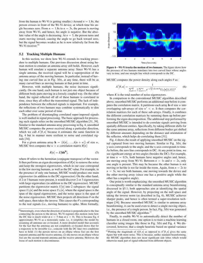
Figure 4—Wi-Vi tracks the motion of two humans. The figure shows howthe presence of two humans translates into two curved lines whose anglesvary in time, and one straight line which corresponds to the DC.
MUSIC computes the power density along each angles ! as:
A![!, n] =1
&Kk=1 ||
&wi=1 e"j 2!
" i! sin !UN [n](i, k)||2. (6)
where K is the total number of noise eigenvectors.In comparison to the conventional MUSIC algorithm described
above, smoothed MUSIC performs an additional step before it com-putes the correlation matrix. It partitions each array h of size w intooverlapping sub-arrays of size w! < w. It then computes the cor-relation matrices for each of these sub-arrays. Finally, it combinesthe different correlation matrices by summing them up before per-forming the eigen decomposition. The additional step performed bysmoothed MUSIC is intended to de-correlate signals arriving fromspatially different entities. Specifically, by taking different shifts forthe same antenna array, reflections from different bodies get shiftedby different amounts depending on the distance and orientation ofthe reflector, which helps de-correlating them [31].
Fig. 4 shows the result of applying smoothed MUSIC on the sig-nal captured from two moving humans. Similar to Fig. 3(b), they-axis corresponds to the angle, and the x-axis corresponds to time.As before, the zero line corresponds to DC. At any point in time, wesee significant energy at two angles (besides the DC). For example,at time n = 0.5s, both humans have negative angles and, hence,are moving away from Wi-Vi. Between n = 1s and n = 2s, onlyone angle is present. This may be because the other human is notmoving or he/she is too far inside the room. Again, from n = 2s ton = 3s, we see both humans, one moving towards the device andthe other moving away (since one has a positive angle while theother has a negative angle).
One point is worth emphasizing: the smoothed MUSIC algorithmis conceptually similar to the standard antenna array beamformingdiscussed in §5.1; both approaches aim at identifying the spatialangle of the signal. However, by projecting on the null space andtaking the inverse norm (as described in Eq. 6), MUSIC achievessharper peaks, and hence is often termed a super-resolution tech-nique [34]. Because smoothed MUSIC is similar to antenna arraybeamforming, it can be used even to detect a single moving object,i.e., the presence of a single person. In fact, Fig. 3(b) was generatedby the smoothed MUSIC algorithm.11
Finally, to enable Wi-Vi to automatically detect the number ofhumans in a closed room, one option is to train a machine learningclassifier using images like those in Fig. 3(b) and Fig. 4. We dis-covered, however, that a simple heuristic based on spatial variance
11Plotting the magnitude of A[!, n] as opposed to A![!, n] gives the samefigure but with more noise. This is because, unlike standard beamforming,the MUSIC algorithm does not incur significant side lobes which wouldotherwise mask part of signal reflected from different objects.
works well in practice. As explained earlier, moving humans appearas curved lines in the 2-D function A![!, n]. Any human can be onlyat one location at any point in time. Thus, at any point in time, thelarger the number of humans, the higher the spatial variance. Thespatial variance is computed as follows. First, Wi-Vi computes thespatial centroid as a function of time:
C[n] =90%
!="90
! · 20 log10 A![!, n], (7)
where A![!, n] is given by Eq. 6. It then computes the spatial vari-ance as:
VAR[n] =90%
!="90
!2 · 20 log10 A![!, n]! C[n]2 (8)
This variance is then averaged over the duration of the experimentto return one number that describes the spatial variance in the roomfor the duration of the measurement. Wi-Vi uses a training set and atesting set to learn the thresholds that separate the spatial variancescorresponding to 0, 1, 2, or 3 humans. The testing and trainingexperiments are conducted in different rooms. In §7.4, we evalu-ate this scheme and measure its ability at automatically capture thenumber of moving humans.
6. THROUGH-WALL GESTURE-BASED COMMU-NICATION
For a human to transmit a message to a computer wirelessly, shetypically has to carry a wireless device. In contrast, Wi-Vi can en-able a human who does not carry any wireless device to commu-nicate commands or short messages to a receiver using simple ges-tures. Wi-Vi designates a pair of gestures as a ‘0’ bit and a ‘1’ bit. Ahuman can compose these gestures to create messages that have dif-ferent interpretations. Additionally, Wi-Vi can evolve by borrowingother existing principles and practices from today’s communicationsystems, such as adding a simple code to ensure reliability, or re-serving a certain pattern of ‘0’s and ‘1’s for packet preambles. Atthis stage, Wi-Vi’s interface is still very basic, yet we believe thatfuture advances in through-wall technology can render this inter-face more expressive.
Below, we describe the gesture-based communication channelthat we implemented with Wi-Vi.
6.1 Gesture EncodingAt the transmitter side, the ‘0’ and ‘1’ bits must be encoded using
some modulation scheme. Wi-Vi implements this encoding usinggestures. One can envision a wide variety of gestures to representthese bits. However, in choosing our encoding we have imposedthree conditions: 1) the gestures must be composable – i.e. at theend of each bit, whether ‘0’ or ‘1’, the human should be back inthe same initial state as the start of the gesture. This enables theperson to compose multiple such gestures to send a longer message.2) The gestures must be simple so that a human finds it easy toperform them and compose them. 3) The gestures should be easyto detect and decode without requiring sophisticated decoders, suchas machine learning classifiers.
Given the above constraints, we have selected the following ges-tures to modulate the bits: a ‘0’ bit is a step forward followed by astep backward; a ‘1’ bit is a step backward followed by a step for-ward. This modulation is similar to Manchester encoding, wherea ‘0’ bit is represented by a falling edge of the clock, (i.e., an in-crease in the signal value followed by a decrease,) and a ‘1’ bit isrepresented by a rising edge of the clock, (i.e., a reduction in sig-
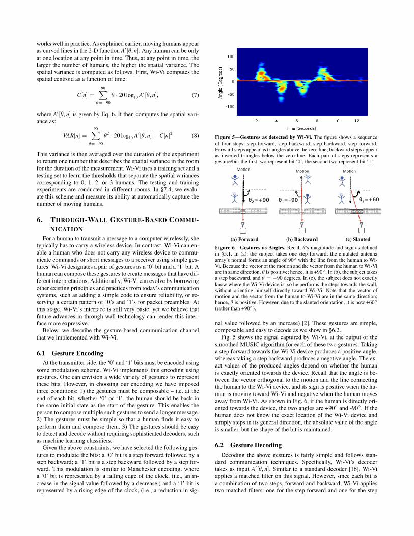
Figure 5—Gestures as detected by Wi-Vi. The figure shows a sequenceof four steps: step forward, step backward, step backward, step forward.Forward steps appear as triangles above the zero line; backward steps appearas inverted triangles below the zero line. Each pair of steps represents agesture/bit: the first two represent bit ‘0’, the second two represent bit ‘1’.
������
�2=+90�
������
�1=-90� �2=+60�
������
(a) Forward (b) Backward (c) SlantedFigure 6—Gestures as Angles. Recall !’s magnitude and sign as definedin §5.1. In (a), the subject takes one step forward; the emulated antennaarray’s normal forms an angle of 90# with the line from the human to Wi-Vi. Because the vector of the motion and the vector from the human to Wi-Viare in same direction, ! is positive; hence, it is +90#. In (b), the subject takesa step backward, and ! = "90 degrees. In (c), the subject does not exactlyknow where the Wi-Vi device is, so he performs the steps towards the wall,without orienting himself directly toward Wi-Vi. Note that the vector ofmotion and the vector from the human to Wi-Vi are in the same direction;hence, ! is positive. However, due to the slanted orientation, it is now +60#(rather than +90#).
nal value followed by an increase) [2]. These gestures are simple,composable and easy to decode as we show in §6.2.
Fig. 5 shows the signal captured by Wi-Vi, at the output of thesmoothed MUSIC algorithm for each of these two gestures. Takinga step forward towards the Wi-Vi device produces a positive angle,whereas taking a step backward produces a negative angle. The ex-act values of the produced angles depend on whether the humanis exactly oriented towards the device. Recall that the angle is be-tween the vector orthogonal to the motion and the line connectingthe human to the Wi-Vi device, and its sign is positive when the hu-man is moving toward Wi-Vi and negative when the human movesaway from Wi-Vi. As shown in Fig. 6, if the human is directly ori-ented towards the device, the two angles are +90# and -90#. If thehuman does not know the exact location of the Wi-Vi device andsimply steps in its general direction, the absolute value of the angleis smaller, but the shape of the bit is maintained.
6.2 Gesture DecodingDecoding the above gestures is fairly simple and follows stan-
dard communication techniques. Specifically, Wi-Vi’s decodertakes as input A![!, n]. Similar to a standard decoder [16], Wi-Viapplies a matched filter on this signal. However, since each bit isa combination of two steps, forward and backward, Wi-Vi appliestwo matched filters: one for the step forward and one for the step

-1500-1000
-500 0
500 1000 1500
0 2 4 6 8 10 12 14
Mat
ched
Out
put
Time (Seconds)(a) Output of matched filter.
-1.5-1
-0.5 0
0.5 1
1.5
0 2 4 6 8 10 12 14
Map
ped
Sym
bols
Time (Seconds)
Bit ‘0’ Bit ‘1’
(b) Decoded bits.Figure 7—Gesture Decoding in Wi-Vi. The figure shows how Wi-Vi de-codes the gestures of Fig. 5. (a) shows the output of the matched filter step.(b) shows the output of the peak detector. The sequence (1,"1) representsbit ‘0’, whereas the sequence ("1, 1) represents bit ‘1’.
backward. Because of the structure of the signal shown in Fig. 5,the two matched filters are simply a triangle above the zero line,and an inverted triangle below the zero line. Wi-Vi applies thesefilters separately on the received signal, then adds up their output.
Fig. 7 shows the results of applying the matched filters on thereceived signal in Fig. 5. Note that the signal after applying thematched filters looks fairly similar to a BPSK signal, where a peakabove the zero line represents a ‘1’ bit and a trough below the zeroline represents a ‘0’ bit. (Though, in Wi-Vi, our encoding is suchthat a peak or a trough alone only represents half a bit.) Next, Wi-Vi uses a standard peak detector to detect the peaks/troughs andmatch them to the corresponding bits. Fig. 7 shows the identifiedpeaks and the detected bits for the two-bit message in Fig. 5.
7. IMPLEMENTATION AND EVALUATIONIn this section, we describe our implementation and the results
of our experimental evaluation.
7.1 ImplementationWe built Wi-Vi using USRP N210 software radios [8] with SBX
daughter boards. The system uses LP0965 directional antennas [3],which provide a gain of 6 dBi. The system consists of three US-RPs connected to an external clock so that they act as one MIMOsystem. Two of the USRPs are used for transmitting, and one forreceiving. MIMO nulling is implemented directly into the UHDdriver, so that it is performed in real-time. Post-processing usingthe smoothed MUSIC algorithm is performed on the obtained tracesoffline in Matlab R2012a under Ubuntu 11.10 on a 64-bit machinewith Intel i7 processor. Matlab already has a built-in and highlyoptimized smoothed MUSIC implementation. Processing traces of25-second length took on average 1.0564s per trace, with a standarddeviation of 0.2561s.
We implement standard Wi-Fi OFDM modulation in the UHDcode; each OFDM symbol consists of 64 subcarriers including theDC. The nulling procedure in §4 is performed on a subcarrier basis.The channel measurements across the different subcarriers are com-bined to improve the SNR. Since USRPs cannot process signals inreal-time at 20 MHz, we reduced the transmitted signal bandwidthto 5 MHz so that our nulling can still run in real time.
Finally, the emulated antenna array was taken over 0.32 seconds.The collected samples during this duration were averaged into anantenna array of size w = 100, which was provided as an input tothe smoothed MUSIC algorithm.
7.2 Experimental SetupMost of our experiments were run in one office building using
two different conference rooms. The rooms have standard furniture:tables, chairs, boards, etc. The interior walls of the building are6-inch hollow walls supported by steel frames with sheet rock ontop. The first conference room is 7 # 4 meters; the second is 11 #7 meters. We also conducted some experiments in a second buildingon our campus which has 8-inch concrete walls.
The experiments were conducted with eight human subjects,three women and five men, of different heights and builds. For thetracking experiments, we asked the subjects to enter a room, closethe door, and move at will. The through-wall gesture experimentswere performed with four subjects (one woman and three men).The persons were shown the gestures in advance and tried thema few times. Then, each of them entered the room separately andperformed the gestures. The experiments are repeated in differentlocations in different rooms, and in different locations in each room.
7.3 Micro BenchmarksFirst, we would like to get a better understanding of the informa-
tion captured by Wi-Vi, and how it relates to the moving objects.We run experiments in two conference rooms in our building. Bothconference rooms have 6!! hollow walls supported by steel frameswith sheet rock on top. In all of these experiments, we position Wi-Vi one meter away from a wall that has neither a door nor a window.For each of our experiments, we ask a number of humans between1 and 3 to enter the room, close the door, and move at will. Wi-Viperforms nulling in real time and collects a trace of the signals. Weperform each experiment with a different subset of our subjects. Weprocess the collected traces using the smoothed MUSIC algorithmas described in §5.2.
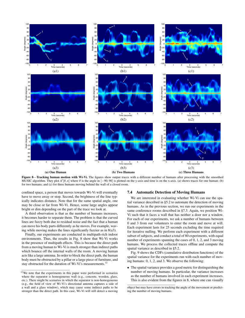
Fig. 8 shows the output of Wi-Vi in the presence of one, two, orthree humans moving in a closed room. Consider the plots with onehuman in Figs. 8(a). Besides the DC, the graphs show one fuzzycurved line. The line tracks the spatial angle of the moving human.Compare these figures with the set of figures in 8(b), which capturetwo moving humans. In 8(b), we can discern two curved lines thattrack the angular motion of these humans with respect to Wi-Vi. Ifwe take a vertical line at any time, in any of the two-human figures,we see at most two bright lines, besides the DC. This is because,in these figures, at any point in time, there are at most two movingbodies in the room. Let us zoom in on the interval [1s, 2s] in 8(b1).During this interval, we see only one curved line. This has two pos-sible interpretations: either one of the two people stopped movingor he/she was too deep inside the room that we could not capturehis/her signal. As we move to 8(c), the figures get fuzzier sincewe have more people moving in the same area. However the gen-eral observations carry to these figures. Specifically, we can identifythe presence of three humans from observing multiple intervals inwhich we can discern three curved lines. For example, consider theinterval [1.8s, 2.5s] in 8(c1); it shows two lines with positive anglesand one with a negative angle. These lines indicate that two peopleare moving towards Wi-Vi, while one person is moving away.
One can also make multiple observations based on the shape ofthe lines. First, a positive angle means the human is moving towardWi-Vi, while a negative angle means that he is moving away. Thevalue of that angle depends on the orientation of the human and thedirection of motion. Each line looks like a wave because, given a
0 1 2 3 4 5 6 7Time (seconds)
-100
-80
-60
-40
-20
0
20
40
60
80
100An
gle
(deg
rees
)
1
1 0 1 2 3 4 5 6 7
Time (seconds)
-100
-80
-60
-40
-20
0
20
40
60
80
100
Angl
e (d
egre
es)
1
2
1
0 1 2 3 4 5 6 7Time (seconds)
-100
-80
-60
-40
-20
0
20
40
60
80
100
Angl
e (d
egre
es)
12
3
(a1) (b1) (c1)
0 1 2 3 4 5 6 7Time (seconds)
-100
-80
-60
-40
-20
0
20
40
60
80
100
Angl
e (d
egre
es)
0 1 2 3 4 5 6 7Time (seconds)
-100
-80
-60
-40
-20
0
20
40
60
80
100
Angl
e (d
egre
es)
1
2
0 1 2 3 4 5 6 7Time (seconds)
-100
-80
-60
-40
-20
0
20
40
60
80
100
Angl
e (d
egre
es)
1
2 3
(a2) (b2) (c2)
0 1 2 3 4 5 6 7Time (seconds)
-100
-80
-60
-40
-20
0
20
40
60
80
100
Angl
e (d
egre
es)
0 1 2 3 4 5 6 7Time (seconds)
-100
-80
-60
-40
-20
0
20
40
60
80
100
Angl
e (d
egre
es)
1
2
0 1 2 3 4 5 6 7Time (seconds)
-100
-80
-60
-40
-20
0
20
40
60
80
100
Angl
e (d
egre
es)
1
2
3
(a3) (b3) (c3)(a) One Human (b) Two Humans (c) Three Humans
Figure 8—Tracking human motion with Wi-Vi. The figures show output traces with a different number of humans after processing with the smoothedMUSIC algorithm. They plot A![!, n] where ! is the angle in ["90, 90] is plotted on the y-axis and time is on the x-axis. (a) shows traces for one human; (b)for two humans; and (c) for three humans moving behind the wall of a closed room.
confined space, a person that moves towards Wi-Vi will eventuallyhave to move away or stop. Second, the brightness of the line typ-ically indicates distance. Note that for the same spatial angle, onemay be close or far from Wi-Vi. Hence, some large angles appearbright or dim depending on the part of the trace we look at.
A third observation is that as the number of humans increases,it becomes harder to separate them. The problem is that the curvedlines are fuzzy both due to residual noise and the fact that a humancan move his body parts differently as he moves. For example, wav-ing while moving makes the lines significantly fuzzier as in 8(a3).
Finally, our experiments are conducted in multipath-rich indoorenvironments. Thus, the results in Fig. 8 show that Wi-Vi worksin the presence of multipath effects. This is because the direct pathfrom a moving human to Wi-Vi is much stronger than indirect pathswhich bounce off the internal walls of the room. A moving humanacts like a large antenna. In order to block the direct path, the humanbody must be obstructed by a pillar or a large piece of furniture, andstay obstructed for the duration of Wi-Vi’s measurements.12
12We note that the experiments in this paper were performed in scenarioswhere the separator is homogeneous wall (e.g., concrete, wooden, glass,etc.). There might be scenarios in which the separator is non-homogeneous(e.g., the field of view of Wi-Vi’s directional antenna captures a side ofa wall and a glass window), which may cause some indirect paths to bestronger than the direct path. In this case, Wi-Vi will still detect a moving
7.4 Automatic Detection of Moving HumansWe are interested in evaluating whether Wi-Vi can use the spa-
tial variance described in §5.2 to automate the detection of movinghumans. As in the previous section, we run our experiments in thesame conference rooms described in §7.3. Again, we position Wi-Vi such that it faces a wall that has neither a door nor a window.For each of our experiments, we ask a number of humans between0 and 3 from our volunteers to enter the room and move at will.Each experiment lasts for 25 seconds excluding the time requiredfor iterative nulling. We perform each experiment with a differentsubset of subjects, and conduct a total of 80 experiments, with equalnumber of experiments spanning the cases of 0, 1, 2, and 3 movinghumans. We process the collected traces offline and compute thespatial variance as described in §5.2.
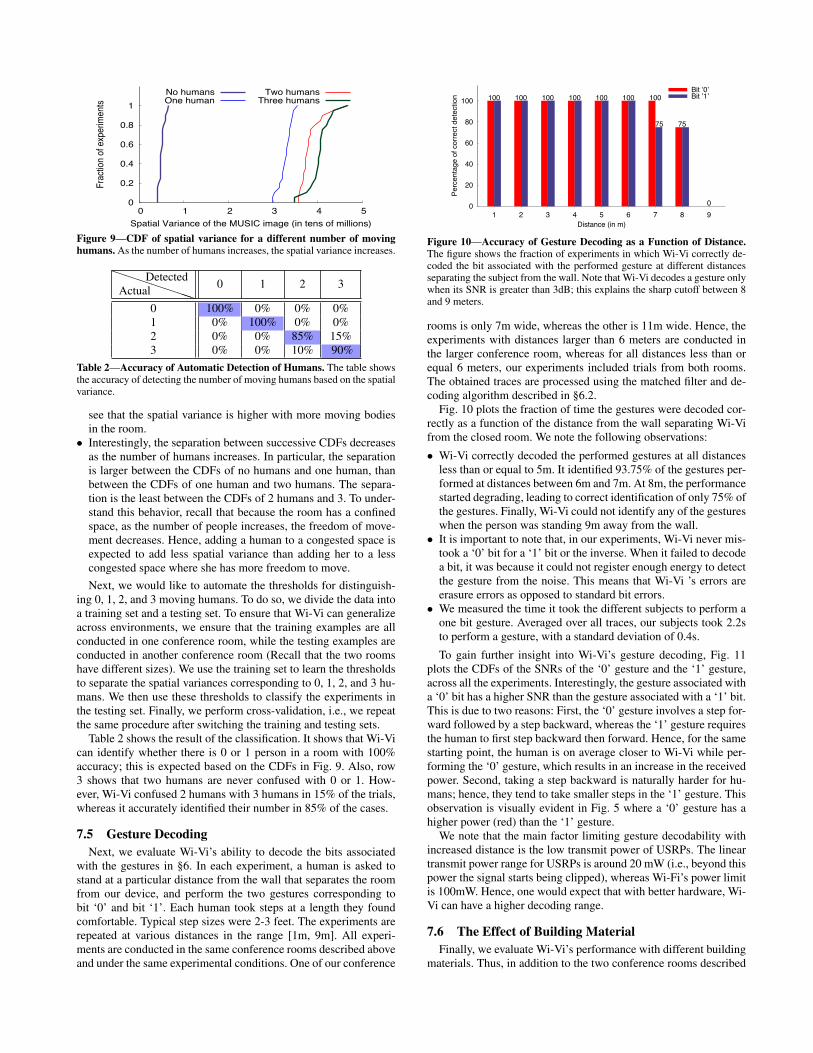
Fig. 9 shows the CDFs (cumulative distribution functions) of thespatial variance for the experiments run with each number of mov-ing humans: 0, 1, 2, and 3. We observe the following:
• The spatial variance provides a good metric for distinguishing thenumber of moving humans. In particular, the variance increasesas the number of humans involved in each experiment increases.This is also evident from the figures in 8, where one can visually
object but may have errors in tracking the angle of the movement or predict-ing the number of moving humans.
0
0.2
0.4
0.6
0.8
1
0 1 2 3 4 5
Frac
tion
of e
xper
imen
ts
Spatial Variance of the MUSIC image (in tens of millions)
No humansOne human
Two humansThree humans
Figure 9—CDF of spatial variance for a different number of movinghumans. As the number of humans increases, the spatial variance increases.
!!!!!!!ActualDetected 0 1 2 3
0 100% 0% 0% 0%1 0% 100% 0% 0%2 0% 0% 85% 15%3 0% 0% 10% 90%
Table 2—Accuracy of Automatic Detection of Humans. The table showsthe accuracy of detecting the number of moving humans based on the spatialvariance.
see that the spatial variance is higher with more moving bodiesin the room.
• Interestingly, the separation between successive CDFs decreasesas the number of humans increases. In particular, the separationis larger between the CDFs of no humans and one human, thanbetween the CDFs of one human and two humans. The separa-tion is the least between the CDFs of 2 humans and 3. To under-stand this behavior, recall that because the room has a confinedspace, as the number of people increases, the freedom of move-ment decreases. Hence, adding a human to a congested space isexpected to add less spatial variance than adding her to a lesscongested space where she has more freedom to move.Next, we would like to automate the thresholds for distinguish-
ing 0, 1, 2, and 3 moving humans. To do so, we divide the data intoa training set and a testing set. To ensure that Wi-Vi can generalizeacross environments, we ensure that the training examples are allconducted in one conference room, while the testing examples areconducted in another conference room (Recall that the two roomshave different sizes). We use the training set to learn the thresholdsto separate the spatial variances corresponding to 0, 1, 2, and 3 hu-mans. We then use these thresholds to classify the experiments inthe testing set. Finally, we perform cross-validation, i.e., we repeatthe same procedure after switching the training and testing sets.
Table 2 shows the result of the classification. It shows that Wi-Vican identify whether there is 0 or 1 person in a room with 100%accuracy; this is expected based on the CDFs in Fig. 9. Also, row3 shows that two humans are never confused with 0 or 1. How-ever, Wi-Vi confused 2 humans with 3 humans in 15% of the trials,whereas it accurately identified their number in 85% of the cases.
7.5 Gesture DecodingNext, we evaluate Wi-Vi’s ability to decode the bits associated
with the gestures in §6. In each experiment, a human is asked tostand at a particular distance from the wall that separates the roomfrom our device, and perform the two gestures corresponding tobit ‘0’ and bit ‘1’. Each human took steps at a length they foundcomfortable. Typical step sizes were 2-3 feet. The experiments arerepeated at various distances in the range [1m, 9m]. All experi-ments are conducted in the same conference rooms described aboveand under the same experimental conditions. One of our conference
Perc
enta
ge o
f cor
rect
det
ectio
n
Distance (in m)
75
Bit ’0’100 100 100 100 100 100 100
75
0
Bit ’1’
0
20
40
60
80
100
1 2 3 4 5 6 7 8 9
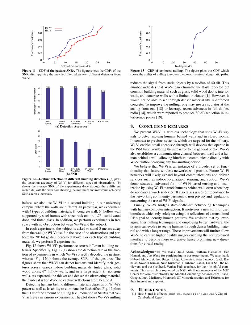
Figure 10—Accuracy of Gesture Decoding as a Function of Distance.The figure shows the fraction of experiments in which Wi-Vi correctly de-coded the bit associated with the performed gesture at different distancesseparating the subject from the wall. Note that Wi-Vi decodes a gesture onlywhen its SNR is greater than 3dB; this explains the sharp cutoff between 8and 9 meters.
rooms is only 7m wide, whereas the other is 11m wide. Hence, theexperiments with distances larger than 6 meters are conducted inthe larger conference room, whereas for all distances less than orequal 6 meters, our experiments included trials from both rooms.The obtained traces are processed using the matched filter and de-coding algorithm described in §6.2.
Fig. 10 plots the fraction of time the gestures were decoded cor-rectly as a function of the distance from the wall separating Wi-Vifrom the closed room. We note the following observations:• Wi-Vi correctly decoded the performed gestures at all distances
less than or equal to 5m. It identified 93.75% of the gestures per-formed at distances between 6m and 7m. At 8m, the performancestarted degrading, leading to correct identification of only 75% ofthe gestures. Finally, Wi-Vi could not identify any of the gestureswhen the person was standing 9m away from the wall.
• It is important to note that, in our experiments, Wi-Vi never mis-took a ‘0’ bit for a ‘1’ bit or the inverse. When it failed to decodea bit, it was because it could not register enough energy to detectthe gesture from the noise. This means that Wi-Vi ’s errors areerasure errors as opposed to standard bit errors.
• We measured the time it took the different subjects to perform aone bit gesture. Averaged over all traces, our subjects took 2.2sto perform a gesture, with a standard deviation of 0.4s.To gain further insight into Wi-Vi’s gesture decoding, Fig. 11
plots the CDFs of the SNRs of the ‘0’ gesture and the ‘1’ gesture,across all the experiments. Interestingly, the gesture associated witha ‘0’ bit has a higher SNR than the gesture associated with a ‘1’ bit.This is due to two reasons: First, the ‘0’ gesture involves a step for-ward followed by a step backward, whereas the ‘1’ gesture requiresthe human to first step backward then forward. Hence, for the samestarting point, the human is on average closer to Wi-Vi while per-forming the ‘0’ gesture, which results in an increase in the receivedpower. Second, taking a step backward is naturally harder for hu-mans; hence, they tend to take smaller steps in the ‘1’ gesture. Thisobservation is visually evident in Fig. 5 where a ‘0’ gesture has ahigher power (red) than the ‘1’ gesture.
We note that the main factor limiting gesture decodability withincreased distance is the low transmit power of USRPs. The lineartransmit power range for USRPs is around 20 mW (i.e., beyond thispower the signal starts being clipped), whereas Wi-Fi’s power limitis 100mW. Hence, one would expect that with better hardware, Wi-Vi can have a higher decoding range.
7.6 The Effect of Building MaterialFinally, we evaluate Wi-Vi’s performance with different building
materials. Thus, in addition to the two conference rooms described
0
0.2
0.4
0.6
0.8
1
0 5 10 15 20 25 30
Frac
tion
of e
xper
imen
ts
SNR of Gestures (in dB)
Bit ’0’Bit ’1’
Figure 11—CDF of the gesture SNRs. The figure shows the CDFs of theSNR after applying the matched filter taken over different distances fromWi-Vi.
Perc
enta
ge o
f cor
rect
det
ectio
n 100 100 100 100
87.5
0
20
40
60
80
100
FreeSpace
TintedGlass
1.75" SolidWood Door
6" HollowWall
8" Concrete
(a) Detection Accuracy
SNR
(in
dB)
0
5
10
15
20
25
30
35
FreeSpace
TintedGlass
1.75" SolidWood Door
6" HollowWall
8" Concrete
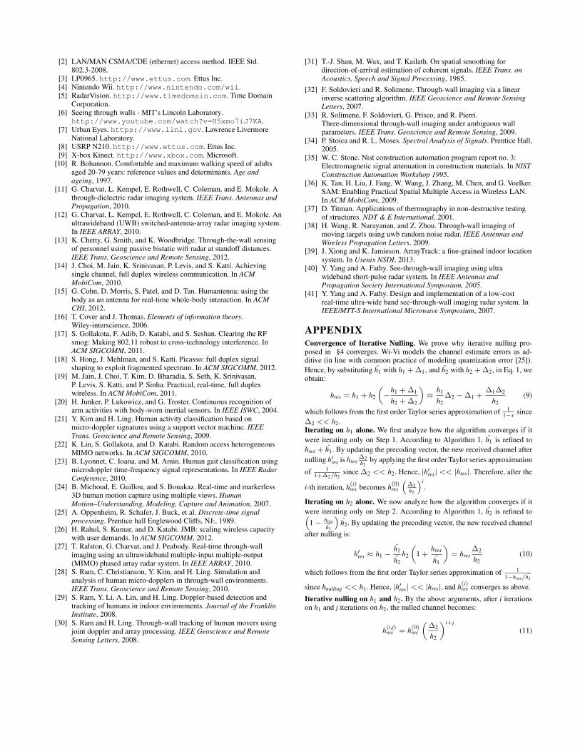
(b) SNRFigure 12—Gesture detection in different building structures. (a) plotsthe detection accuracy of Wi-Vi for different types of obstructions. (b)shows the average SNR of the experiments done through these differentmaterials, with the error bars showing the minimum and maximum achievedSNRs across the trials.
before, we also test Wi-Vi in a second building in our universitycampus, where the walls are different. In particular, we experimentwith 4 types of building materials: 8!! concrete wall, 6!! hollow wallsupported by steel frames with sheet rock on top, 1.75!! solid wooddoor, and tinted glass. In addition, we perform experiments in freespace with no obstruction between Wi-Vi and the subject.
In each experiment, the subject is asked to stand 3 meters awayfrom the wall (or Wi-Vi itself in the case of no obstruction) and per-form the ‘0’ bit gesture described above. For each type of buildingmaterial, we perform 8 experiments.
Fig. 12 shows Wi-Vi’s performance across different building ma-terials. Specifically, Fig. 12(a) shows the detection rate as the frac-tion of experiments in which Wi-Vi correctly decoded the gesture,whereas Fig. 12(b) shows the average SNRs of the gestures. Thefigures show that Wi-Vi can detect humans and identify their ges-tures across various indoor building materials: tinted glass, solidwood doors, 6!! hollow walls, and to a large extent 8!! concretewalls. As expected, the thicker and denser the obstructing material,the harder it is for Wi-Vi to capture reflections from behind it.
Detecting humans behind different materials depends on Wi-Vi’spower as well as its ability to eliminate the flash effect. Fig. 13 plotsthe CDF of the amount of nulling (i.e., reduction in SNRs) that Wi-Vi achieves in various experiments. The plot shows Wi-Vi’s nulling
0
0.2
0.4
0.6
0.8
1
0 10 20 30 40 50 60
Frac
tion
of e
xper
imen
ts
Nulling (in dB)
Figure 13—CDF of achieved nulling. The figure plots the CDF whichshows the ability of nulling to reduce the power received along static paths.
reduces the signal from static objects by a median of 40 dB. Thisnumber indicates that Wi-Vi can eliminate the flash reflected offcommon building material such as glass, solid wood doors, interiorwalls, and concrete walls with a limited thickness [1]. However, itwould not be able to see through denser material like re-enforcedconcrete. To improve the nulling, one may use a circulator at theanalog front end [18] or leverage recent advances in full-duplexradio [14], which were reported to produce 80 dB reduction in in-terference power [19].
8. CONCLUDING REMARKSWe present Wi-Vi, a wireless technology that uses Wi-Fi sig-
nals to detect moving humans behind walls and in closed rooms.In contrast to previous systems, which are targeted for the military,Wi-Vi enables small cheap see-through-wall devices that operate inthe ISM band, rendering them feasible to the general public. Wi-Vialso establishes a communication channel between itself and a hu-man behind a wall, allowing him/her to communicate directly withWi-Vi without carrying any transmitting device.
We believe that Wi-Vi is an instance of a broader set of func-tionality that future wireless networks will provide. Future Wi-Finetworks will likely expand beyond communications and deliverservices such as indoor localization, sensing, and control. Wi-Videmonstrates an advanced form of Wi-Fi-based sensing and local-ization by using Wi-Fi to track humans behind wall, even when theydo not carry a wireless device. It also raises issues of importance tothe networking community pertinent to user privacy and regulationsconcerning the use of Wi-Fi signals.
Finally, Wi-Vi bridges state-of-the-art networking techniqueswith human-computer interaction. It motivates a new form of userinterfaces which rely solely on using the reflections of a transmittedRF signal to identify human gestures. We envision that by lever-aging finer nulling techniques and employing better hardware, thesystem can evolve to seeing humans through denser building mate-rial and with a longer range. These improvements will further allowWi-Vi to capture higher quality images enabling the gesture-basedinterface to become more expressive hence promising new direc-tions for virtual reality.
Acknowledgments: We thank Omid Abari, Haitham Hassanieh, EzzHamad, and Jue Wang for participating in our experiments. We also thankNabeel Ahmed, Arthur Berger, Diego Cifuentes, Peter Iannucci, Zack Ka-belac, Swarun Kumar, Nate Kushman, Hariharan Rahul, Lixin Shi, the re-viewers, and our shepherd, Venkat Padmanabhan, for their insightful com-ments. This research is supported by NSF. We thank members of the MITCenter for Wireless Networks and Mobile Computing: Amazon.com, Cisco,Google, Intel, Mediatek, Microsoft, ST Microelectronics, and Telefonica fortheir interest and support.
9. REFERENCES[1] How Signal is affected. www.ci.cumberland.md.us/. City of
Cumberland Report.
[2] LAN/MAN CSMA/CDE (ethernet) access method. IEEE Std.802.3-2008.
[3] LP0965. http://www.ettus.com. Ettus Inc.[4] Nintendo Wii. http://www.nintendo.com/wii.[5] RadarVision. http://www.timedomain.com. Time Domain
Corporation.[6] Seeing through walls - MIT’s Lincoln Laboratory.
http://www.youtube.com/watch?v=H5xmo7iJ7KA.[7] Urban Eyes. https://www.llnl.gov. Lawrence Livermore
National Laboratory.[8] USRP N210. http://www.ettus.com. Ettus Inc.[9] X-box Kinect. http://www.xbox.com. Microsoft.
[10] R. Bohannon. Comfortable and maximum walking speed of adultsaged 20-79 years: reference values and determinants. Age andageing, 1997.
[11] G. Charvat, L. Kempel, E. Rothwell, C. Coleman, and E. Mokole. Athrough-dielectric radar imaging system. IEEE Trans. Antennas andPropagation, 2010.
[12] G. Charvat, L. Kempel, E. Rothwell, C. Coleman, and E. Mokole. Anultrawideband (UWB) switched-antenna-array radar imaging system.In IEEE ARRAY, 2010.
[13] K. Chetty, G. Smith, and K. Woodbridge. Through-the-wall sensingof personnel using passive bistatic wifi radar at standoff distances.IEEE Trans. Geoscience and Remote Sensing, 2012.
[14] J. Choi, M. Jain, K. Srinivasan, P. Levis, and S. Katti. Achievingsingle channel, full duplex wireless communication. In ACMMobiCom, 2010.
[15] G. Cohn, D. Morris, S. Patel, and D. Tan. Humantenna: using thebody as an antenna for real-time whole-body interaction. In ACMCHI, 2012.
[16] T. Cover and J. Thomas. Elements of information theory.Wiley-interscience, 2006.
[17] S. Gollakota, F. Adib, D. Katabi, and S. Seshan. Clearing the RFsmog: Making 802.11 robust to cross-technology interference. InACM SIGCOMM, 2011.
[18] S. Hong, J. Mehlman, and S. Katti. Picasso: full duplex signalshaping to exploit fragmented spectrum. In ACM SIGCOMM, 2012.
[19] M. Jain, J. Choi, T. Kim, D. Bharadia, S. Seth, K. Srinivasan,P. Levis, S. Katti, and P. Sinha. Practical, real-time, full duplexwireless. In ACM MobiCom, 2011.
[20] H. Junker, P. Lukowicz, and G. Troster. Continuous recognition ofarm activities with body-worn inertial sensors. In IEEE ISWC, 2004.
[21] Y. Kim and H. Ling. Human activity classification based onmicro-doppler signatures using a support vector machine. IEEETrans. Geoscience and Remote Sensing, 2009.
[22] K. Lin, S. Gollakota, and D. Katabi. Random access heterogeneousMIMO networks. In ACM SIGCOMM, 2010.
[23] B. Lyonnet, C. Ioana, and M. Amin. Human gait classification usingmicrodoppler time-frequency signal representations. In IEEE RadarConference, 2010.
[24] B. Michoud, E. Guillou, and S. Bouakaz. Real-time and markerless3D human motion capture using multiple views. HumanMotion–Understanding, Modeling, Capture and Animation, 2007.
[25] A. Oppenheim, R. Schafer, J. Buck, et al. Discrete-time signalprocessing. Prentice hall Englewood Cliffs, NJ:, 1989.
[26] H. Rahul, S. Kumar, and D. Katabi. JMB: scaling wireless capacitywith user demands. In ACM SIGCOMM, 2012.
[27] T. Ralston, G. Charvat, and J. Peabody. Real-time through-wallimaging using an ultrawideband multiple-input multiple-output(MIMO) phased array radar system. In IEEE ARRAY, 2010.
[28] S. Ram, C. Christianson, Y. Kim, and H. Ling. Simulation andanalysis of human micro-dopplers in through-wall environments.IEEE Trans. Geoscience and Remote Sensing, 2010.
[29] S. Ram, Y. Li, A. Lin, and H. Ling. Doppler-based detection andtracking of humans in indoor environments. Journal of the FranklinInstitute, 2008.
[30] S. Ram and H. Ling. Through-wall tracking of human movers usingjoint doppler and array processing. IEEE Geoscience and RemoteSensing Letters, 2008.
[31] T.-J. Shan, M. Wax, and T. Kailath. On spatial smoothing fordirection-of-arrival estimation of coherent signals. IEEE Trans. onAcoustics, Speech and Signal Processing, 1985.
[32] F. Soldovieri and R. Solimene. Through-wall imaging via a linearinverse scattering algorithm. IEEE Geoscience and Remote SensingLetters, 2007.
[33] R. Solimene, F. Soldovieri, G. Prisco, and R. Pierri.Three-dimensional through-wall imaging under ambiguous wallparameters. IEEE Trans. Geoscience and Remote Sensing, 2009.
[34] P. Stoica and R. L. Moses. Spectral Analysis of Signals. Prentice Hall,2005.
[35] W. C. Stone. Nist construction automation program report no. 3:Electromagnetic signal attenuation in construction materials. In NISTConstruction Automation Workshop 1995.
[36] K. Tan, H. Liu, J. Fang, W. Wang, J. Zhang, M. Chen, and G. Voelker.SAM: Enabling Practical Spatial Multiple Access in Wireless LAN.In ACM MobiCom, 2009.
[37] D. Titman. Applications of thermography in non-destructive testingof structures. NDT & E International, 2001.
[38] H. Wang, R. Narayanan, and Z. Zhou. Through-wall imaging ofmoving targets using uwb random noise radar. IEEE Antennas andWireless Propagation Letters, 2009.
[39] J. Xiong and K. Jamieson. ArrayTrack: a fine-grained indoor locationsystem. In Usenix NSDI, 2013.
[40] Y. Yang and A. Fathy. See-through-wall imaging using ultrawideband short-pulse radar system. In IEEE Antennas andPropagation Society International Symposium, 2005.
[41] Y. Yang and A. Fathy. Design and implementation of a low-costreal-time ultra-wide band see-through-wall imaging radar system. InIEEE/MTT-S International Microwave Symposium, 2007.
APPENDIXConvergence of Iterative Nulling. We prove why iterative nulling pro-posed in §4 converges. Wi-Vi models the channel estimate errors as ad-ditive (in line with common practice of modeling quantization error [25]).Hence, by substituting h1 with h1 +!1, and h2 with h2 +!2, in Eq. 1, weobtain:
hres = h1 + h2
#"
h1 +!1
h2 +!2
$#
h1
h2!2 "!1 +
!1!2
h2(9)
which follows from the first order Taylor series approximation of 11"x since
!2 << h2.Iterating on h1 alone. We first analyze how the algorithm converges if itwere iterating only on Step 1. According to Algorithm 1, h1 is refined tohres + h1. By updating the precoding vector, the new received channel afternulling h!res is hres
!2h2
by applying the first order Taylor series approximation
of 11+!2/h2
since !2 << h2. Hence, |h!res| << |hres|. Therefore, after the
i-th iteration, h(i)res becomes h(0)
res
!!2h2
"i.
Iterating on h2 alone. We now analyze how the algorithm converges if itwere iterating only on Step 2. According to Algorithm 1, h2 is refined to!
1" hresh1
"h2. By updating the precoding vector, the new received channel
after nulling is:
h!res # h1 "h1
h2h2
#1 +
hres
h1
$= hres
!2
h2(10)
which follows from the first order Taylor series approximation of 11"hres/h1
since hnulling << h1. Hence, |h!res| << |hres|, and h(i)res converges as above.
Iterative nulling on h1 and h2. By the above arguments, after i iterationson h1 and j iterations on h2, the nulled channel becomes:
h(i,j)res = h(0)
res
#!2
h2
$i+j(11)