Embed Size (px)
Citation preview

See Through Walls with Wi-Fi
by
Fadel Adib
Submitted to the Department of Electrical Engineering and Computer Science
in partial fulfillment of the requirements for the degree of
Master of Science in Computer Science and Engineering
at the
MASSACHUSETTS INSTITUTE OF TECHNOLOGY
June 2013
c© Massachusetts Institute of Technology 2013. All rights reserved.
Author . . . . . . . . . . . . . . . . . . . . . . . . . . . . . . . . . . . . . . . . . . . . . . . . . . . . . . . . . . . . . .Department of Electrical Engineering and Computer Science
May 22, 2013
Certified by. . . . . . . . . . . . . . . . . . . . . . . . . . . . . . . . . . . . . . . . . . . . . . . . . . . . . . . . . .Dina Katabi
ProfessorThesis Supervisor
Accepted by . . . . . . . . . . . . . . . . . . . . . . . . . . . . . . . . . . . . . . . . . . . . . . . . . . . . . . . . .Leslie A. Kolodziejski
Chairman, Department Committee on Graduate Students

2

See Through Walls with Wi-Fi
by
Fadel Adib
Submitted to the Department of Electrical Engineering and Computer Scienceon May 22, 2013, in partial fulfillment of the
requirements for the degree ofMaster of Science in Computer Science and Engineering
Abstract
Wi-Fi signals are typically information carriers between a transmitter and a receiver.In this thesis, we show that Wi-Fi can also extend our senses, enabling us to seemoving objects through walls and behind closed doors. For example, we can identifythe number of people in a closed room and their relative locations. We can alsoidentify simple gestures made behind a wall. Further, by combining a sequence ofgestures, a human can communicate messages to a wireless receiver without carryingany transmitting device. The thesis introduces two main innovations. First, it showshow one can use MIMO interference nulling to eliminate reflections off static objectsand focus the receiver on a moving target. Second, it shows how one can track ahuman by treating the motion of a human body as an antenna array and trackingthe resulting RF beam. We demonstrate the validity of our design by building it intoUSRP software radios and testing it in office buildings.
Thesis Supervisor: Dina KatabiTitle: Professor
3

4

To Salam, My Guardian Angel

6

Acknowledgments
This research was performed under the supervision of Professor Dina Katabi, and it
was published in ACM SIGCOMM 2013. My first year of graduate studies was gen-
erously supported by the Irwin and Joan Jacobs Presidential Fellowship. In addition,
this work was partially supported by the National Science Foundation.
I would like to thank Dina for embodying what an ideal researcher, supervisor,
and mentor would be. I could write essays about how and why I believe I am genuinely
blessed to have her as my adviser. I am tremendously excited about my research in
the coming few years and about my incessant learning experience with Dina.
I am grateful to my friends in the NETMIT group for helping me at different stages
of this project and for their wonderful company. I thank Omid, Ezz, Haitham, and
Jue for unwaveringly volunteering in hundreds of experiments. I thank Haitham and
Swarun for helping me shoot the video for Wi-Vi. I owe many thanks to Jue for her
instrumental discussions with me at different stages of developing Wi-Vi. In addition,
I thank Nabeel, Arthur, Diego, Peter, Zach, Nate, Rahul, and Lixin for their helpful
feedback on the paper before the SIGCOMM submission. I would like to single out
Nabeel and Rahul for being great sources of advice for me. Finally, special thanks to
Shyam, Nate, and Haitham for showing me the ropes to wireless and systems research.
I have also been very fortunate to share the first years of my MIT adventure with
an extraordinary group of friends. I thank my best friend, Jad, for never failing to be
a source of incredible support, happiness, and comfort. I thank my amazing friend,
Deeni, for cheering me up and pushing me forward on my most frustrating days. I
thank Mohammad, Ragheb, Tawfiq, Obaidah, and Amer for reminding me why MIT
is my home, and Sana, Hala, Salim, Nour, Maya, and Ruba for reminding me of home.
Finally, yet most importantly, words cannot express my gratitude towards my par-
ents, Salam and Fawaz, my sister, Hayat, and my brother, Ahmad, for their perpetual
support, guidance, sacrifices, and love. And in a final word, transcendent to gratitude,
I turn to my mother, Salam, my torch of guidance, inspiration, and motivation: thank
you for making me the person I am; this thesis is dedicated to you.
7

8

Contents
1 Introduction 13
1.1 Seeing Through Walls with Wi-Fi . . . . . . . . . . . . . . . . . . . . 14
1.2 Evaluation of Wi-Vi . . . . . . . . . . . . . . . . . . . . . . . . . . . 16
1.3 Contributions . . . . . . . . . . . . . . . . . . . . . . . . . . . . . . . 18
2 Related Work 19
2.1 Through-wall Radar . . . . . . . . . . . . . . . . . . . . . . . . . . . 19
2.2 Gesture-based Interfaces . . . . . . . . . . . . . . . . . . . . . . . . . 20
2.3 Infrared and Thermal Imaging . . . . . . . . . . . . . . . . . . . . . . 21
3 Wi-Vi Overview 23
3.1 Device Description . . . . . . . . . . . . . . . . . . . . . . . . . . . . 23
3.2 Device Operation . . . . . . . . . . . . . . . . . . . . . . . . . . . . . 23
4 Eliminating the Flash 25
4.1 Nulling to Remove the Flash . . . . . . . . . . . . . . . . . . . . . . . 26
4.1.1 Initial Nulling . . . . . . . . . . . . . . . . . . . . . . . . . . . 26
4.1.2 Power Boosting . . . . . . . . . . . . . . . . . . . . . . . . . . 27
4.1.3 Iterative Nulling . . . . . . . . . . . . . . . . . . . . . . . . . 28
5 Identifying and Tracking Humans 31
5.1 Tracking a Single Human . . . . . . . . . . . . . . . . . . . . . . . . . 31
5.2 Tracking Multiple Humans . . . . . . . . . . . . . . . . . . . . . . . . 35
9
6 Through-Wall Gesture-Based Communication 39
6.1 Gesture Encoding . . . . . . . . . . . . . . . . . . . . . . . . . . . . . 39
6.2 Gesture Decoding . . . . . . . . . . . . . . . . . . . . . . . . . . . . . 41
7 Implementation and Evaluation 43
7.1 Implementation . . . . . . . . . . . . . . . . . . . . . . . . . . . . . . 43
7.2 Experimental Setup . . . . . . . . . . . . . . . . . . . . . . . . . . . . 44
7.3 Micro Benchmarks . . . . . . . . . . . . . . . . . . . . . . . . . . . . 44
7.4 Automatic Detection of Moving Humans . . . . . . . . . . . . . . . . 47
7.5 Gesture Decoding . . . . . . . . . . . . . . . . . . . . . . . . . . . . . 49
7.6 The Effect of Building Material . . . . . . . . . . . . . . . . . . . . . 51
8 Conclusion 55
10

List of Figures
1-1 A Moving Object as an Antenna Array. In (a), an antenna array is able to locate
an object by steering its beam spatially. In (b), the moving object itself emulates an
antenna array; hence, it acts as an inverse synthetic aperture. Wi-Vi leverages this
principle in order to beamform the received signal in time (rather than in space) and
locate the moving object. . . . . . . . . . . . . . . . . . . . . . . . . . . . . . . . . . 16
5-1 Time samples as Antenna Arrays. Wi-Vi groups consecutive time samples into
overlapping windows of size w, then treats each window h[n] . . . h[n+w ] as an antenna
array. This allows it to track the direction of a moving object with respect to the receiver. 33
5-2 Wi-Vi tracks a single person’s motion. (a) shows the experimental setup of a
trial which consisted of a single person moving around in a conference room. (b) shows
how Wi-Vi is able to track the motion of the person by computing the variation of
the inverse angle of arrival with time, i.e. A′[θ,n] for θ in [−90◦, 90◦]. . . . . . . . . . 34
5-3 Wi-Vi tracks the motion of two humans. The figure shows how the presence of
2 humans translates into 2 curved lines whose angles vary in time, and one straight
line which corresponds to the DC. . . . . . . . . . . . . . . . . . . . . . . . . . . . . 37
6-1 Gestures as detected by Wi-Vi. The figure shows a sequence of four gestures:
step forward, step backward, step backward, step forward. Forward steps appear as
triangles above the zero line; backward steps appear as inverted triangles below the
zero line. Each pair of gestures represents a bit: the first two represent bit ‘0’, the
second two represent bit ‘1’. . . . . . . . . . . . . . . . . . . . . . . . . . . . . . . . . 40
11

6-2 Gestures as Angles. Recall θ’s magnitude and sign as defined in §5.1. In (a), the
subject takes one step forward; the emulated antenna array’s normal forms an angle of
90◦ with the line from the human to Wi-Vi. Because the vector of the motion and the
vector from the human to Wi-Vi are in same direction, θ is positive; hence, it is +90◦.
In (b), the subject takes a step backward, and θ = −90 degrees. In (c), the subject
does not exactly know where the Wi-Vi device is, so he performs the steps towards
the wall, without orienting himself directly toward Wi-Vi. Note that the vector of
motion and the vector from the human to Wi-Vi are in the same direction; hence, θ
is positive. However, due to the slanted orientation, it is now +60◦ (rather than +90◦). 41
6-3 Gesture Decoding in Wi-Vi. The figure shows how Wi-Vi decodes the gestures of
Fig. 6-1. (a) shows the output of the matched filter step. (b) shows the output of the
peak detector. The sequence (1,−1) represents bit ‘0’, whereas the sequence (−1, 1)
represents bit ‘1’. . . . . . . . . . . . . . . . . . . . . . . . . . . . . . . . . . . . . . . 42
7-1 Tracking human motion with Wi-Vi. The figures show output traces with a
different number of humans after processing with the smoothed MUSIC algorithm.
They plot A′[θ,n] where θ is the angle in [−90, 90] is plotted on the y-axis and time is
on the x-axis. (a) shows traces for one human; (b) for two humans; and (c) for three
humans moving behind the wall of a closed room. . . . . . . . . . . . . . . . . . . . . 46
7-2 CDF of spatial variance for a different number of moving humans. As the
number of humans increases, the spatial variance increases. . . . . . . . . . . . . . . 48
7-3 Accuracy of Gesture Decoding as a Function of Distance. The figure shows
the fraction of experiments in which Wi-Vi correctly decoded the bit associated with
the performed gesture at different distances separating the subject from the wall. Note
that Wi-Vi decodes a gesture only when its SNR is greater than 3dB; this explains
the sharp cutoff between 8 and 9 meters. . . . . . . . . . . . . . . . . . . . . . . . . 51
7-4 CDF of the gesture SNRs. The figure shows the CDFs of the SNR after applying
the matched filter taken over different distances from Wi-Vi. . . . . . . . . . . . . . 52
7-5 Gesture detection in different building structures. (a) plots the detection ac-
curacy of Wi-Vi for different types of obstructions. (b) shows the average SNR of the
experiments done through these different materials, with the error bars showing the
minimum and maximum achieved SNRs across the trials. . . . . . . . . . . . . . . . 53
7-6 CDF of achieved nulling. The figure plots the CDF which shows the ability of
nulling to reduce the power received along static paths. . . . . . . . . . . . . . . . . 53
12

Chapter 1
Introduction
Science is my territory, but science fiction is the landscape of my dreams.
- Freeman Dyson, Theoretical Physicist
Can Wi-Fi signals enable us to see through walls? For many years, humans have
fantasized about X-ray vision and played with the concept in comic books and sci-fi
movies. This thesis explores the potential of using Wi-Fi signals and recent advances
in MIMO communications to build a device that can capture the motion of humans
behind a wall and in closed rooms. Law enforcement personnel can use the device
to avoid walking into an ambush, and minimize casualties in standoffs and hostage
situations. Emergency responders can use it to see through rubble and collapsed
structures. Ordinary users can leverage the device for gaming, intrusion detection,
privacy-enhanced monitoring of children and elderly, or personal security when step-
ping into dark alleys and unknown places.
The concept underlying seeing through opaque obstacles is similar to radar and
sonar imaging. Specifically, when faced with a non-metallic wall, a fraction of the RF
signal would penetrate the wall, reflect off objects and humans, and come back im-
printed with a signature of what is inside a closed room. By capturing these reflections,
we can image objects behind a wall. Building a device that can capture such reflec-
tions, however, is difficult because the signal power after traversing the wall twice (in
and out of the room) is reduced by three to five orders of magnitude [13]. Even more
13

challenging are the reflections from the wall itself, which are much stronger than the
reflections from objects inside the room [13, 28]. Reflections off the wall overwhelm
the receiver’s analog to digital converter (ADC), preventing it from registering the
minute variations due to reflections from objects behind the wall. This behavior is
called the “Flash Effect” since it is analogous to how a mirror in front of a camera
reflects the camera’s flash and prevents it from capturing objects in the scene.
So how can one overcome these difficulties? The radar community has been in-
vestigating these issues, and has recently introduced a few ultra-wideband systems
that can detect humans moving behind a wall, and show them as blobs moving in a
dim background [28, 41] (see the video at [6] for a reference). Today’s state-of-the-
art system requires 2 GHz of bandwidth, a large power source, and an 8-foot long
antenna array (2.4 meters) [12, 28]. Apart from the bulkiness of the device, blasting
power in such a wide spectrum is infeasible for entities other than the military. The
requirement for multi-GHz transmission is at the heart of how these systems work:
they separate reflections off the wall from reflections from the objects behind the
wall based on their arrival time, and hence need to identify sub-nanosecond delays
(i.e., multi-GHz bandwidth) to filter the flash effect.1 To address these limitations, an
initial attempt was made in 2012 to use Wi-Fi to see through a wall [14]. However,
to mitigate the flash effect, this past proposal needs to install an additional receiver
behind the wall, and connect the receivers behind and in-front of the wall to a joint
clock via wires [14].
1.1 Seeing Through Walls with Wi-Fi
The objective of this thesis is to enable a see-through-wall technology that is low-
bandwidth, low-power, compact, and accessible to non-military entities. To this end,
the thesis introduces Wi-Vi2, a see-through-wall device that employs Wi-Fi signals in
the 2.4 GHz ISM band. Wi-Vi limits itself to a 20 MHz-wide Wi-Fi channel, and avoids
1The filtering is done in the analog domain before the signal reaches the ADC.2Wi-Vi stands for Wi-Fi Vision.
14
ultra-wideband solutions used today to address the flash effect. It also disposes of the
large antenna array, typical in past systems, and uses instead a smaller 3-antenna
MIMO radio.
So, how does Wi-Vi eliminate the flash effect without using GHz of bandwidth?
We observe that we can adapt recent advances in MIMO communications to through-
wall imaging. In MIMO, multiple antenna systems can encode their transmissions
so that the signal is nulled (i.e., sums up to zero) at a particular receive antenna.
MIMO systems use this capability to eliminate interference to unwanted receivers. In
contrast, we use nulling to eliminate reflections from static objects, including the wall.
Specifically, a Wi-Vi device has two transmit antennas and a single receive antenna.
Wi-Vi operates in two stages. In the first stage, it measures the channels from each of
its two transmit antennas to its receive antenna. In stage 2, the two transmit antennas
use the channel measurements from stage 1 to null the signal at the receive antenna.
Since wireless signals (including reflections) combine linearly over the medium, only
reflections off objects that move between the two stages are captured in stage 2.
Reflections off static objects, including the wall, are nulled in this stage. In §4, we
refine this basic idea by introducing iterative nulling, which allows us to eliminate
residual flash and the weaker reflections from static objects behind the wall.
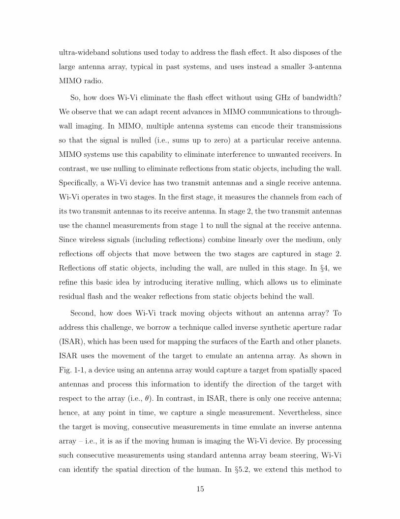
Second, how does Wi-Vi track moving objects without an antenna array? To
address this challenge, we borrow a technique called inverse synthetic aperture radar
(ISAR), which has been used for mapping the surfaces of the Earth and other planets.
ISAR uses the movement of the target to emulate an antenna array. As shown in
Fig. 1-1, a device using an antenna array would capture a target from spatially spaced
antennas and process this information to identify the direction of the target with
respect to the array (i.e., θ). In contrast, in ISAR, there is only one receive antenna;
hence, at any point in time, we capture a single measurement. Nevertheless, since
the target is moving, consecutive measurements in time emulate an inverse antenna
array – i.e., it is as if the moving human is imaging the Wi-Vi device. By processing
such consecutive measurements using standard antenna array beam steering, Wi-Vi
can identify the spatial direction of the human. In §5.2, we extend this method to
15

θ!
"#$%##&!"''&(!
)$&*+#&'(!
"#$!%#&$##'!
()*$+,-#!-.!/-,-#!()*$+,-#!-.!/-,-#!
θ!
(a) Antenna Array (b) ISAR
Figure 1-1: A Moving Object as an Antenna Array. In (a), an antenna arrayis able to locate an object by steering its beam spatially. In (b), the moving objectitself emulates an antenna array; hence, it acts as an inverse synthetic aperture. Wi-Vileverages this principle in order to beamform the received signal in time (rather thanin space) and locate the moving object.
multiple moving targets.
Additionally, Wi-Vi leverages its ability to track motion to enable a through-
wall gesture-based communication channel. Specifically, a human can communicate
messages to a Wi-Vi receiver via gestures without carrying any wireless device. We
have picked two simple body gestures to refer to “0” and “1” bits. A human behind
a wall may use a short sequence of these gestures to send a message to Wi-Vi. After
applying a matched filter, the message signal looks similar to standard BPSK encoding
(a positive signal for a “1” bit, and a negative signal for a “0” bit) and can be decoded
by considering the sign of the signal. The system enables law enforcement personnel
to communicate with their team across a wall, even if their communication devices
are confiscated.
1.2 Evaluation of Wi-Vi
We built a prototype of Wi-Vi using USRP N210 radios and evaluated it in two office
buildings. Our results are as follows:
• Wi-Vi can detect objects and humans moving behind opaque structural ob-
structions. This applies to 8′′ concrete walls, 6′′ hollow walls, and 1.75′′ solid
16

wooden doors. The video available in [9] shows a demo of how Wi-Vi tracks a
moving human from behind a wall.
• A Wi-Vi device pointed at a closed room with 6′′ hollow walls supported by
steel frames can distinguish between 0, 1, 2, and 3 moving humans in the room.
The precisions with which Wi-Vi identifies each case, computed over 80 trials
with 8 human subjects, are 100%, 100%, 85% and 90% respectively.
• In the same room, and given a single person sending gesture-based messages,
Wi-Vi correctly decodes all messages performed at distances equal to or smaller
than 5 meters. The decoding accuracy decreases to 75% at distances of 8 meters,
and the device stops detecting gestures beyond 9 meters. For 8 volunteers who
participated in the experiment, on average, it took a person 8.8 seconds to send
a message of 4 gestures.
• In comparison to the state-of-the-art ultra-wideband see-through-wall radar [28],
Wi-Vi is limited in two ways. First, replacing the antenna array by ISAR means
that the angular resolution in Wi-Vi depends on the amount of movement. To
achieve a narrow beam, the human needs to move by about 4 wavelengths (i.e.,
about 50 cm). Second, in contrast to [28], we cannot detect humans behind
concrete walls thicker than 8′′. This is due to both the much lower transmit
power from our USRPs and the residual flash power from imperfect nulling.
On the other hand, nulling the flash removes the need for GHz bandwidth. It
also removes clutter from all static reflectors, rather than just one wall. This
includes other walls in the environments as well as furniture inside and outside
the imaged room. To reduce clutter, the empirical results in past work are typ-
ically collected using a person-height standing wall, positioned either outdoors
or in large empty indoor spaces [28, 41]. In contrast, our experiments are in
standard office buildings with the imaged humans inside closed fully-furnished
rooms.
17

1.3 Contributions
In contrast to past work which targets the military, Wi-Vi introduces novel solutions
to the see-through-wall problem that enable non-military entities to use this technol-
ogy. Specifically, Wi-Vi is the first to introduce interference nulling as a mechanism
for eliminating the flash effect without requiring wideband spectrum. It is also the
first to replace the antenna array at the receiver with an emulated array based on hu-
man motion. The combination of those techniques enables small cheap devices that
operate in the ISM band, and can be made accessible to the general public. Fur-
ther, Wi-Vi is the first to demonstrate a gesture-based communication channel that
operates through walls and does not require the human to carry any wireless device.
18

Chapter 2
Related Work
Wi-Vi is related to past work in three major areas.
2.1 Through-wall Radar
Interest in through-wall imaging has been surging for about a decade [5]. Earlier work
in this domain focused on simulations [39, 29] and modeling [33, 34]. Recently, there
have been some implementations tested with moving humans [28, 41, 14]. These past
systems eliminate the flash effect by isolating the signal reflected off the wall from
signals reflected off objects behind the wall. This isolation can be achieved in the time
domain, by using very short pulses (less than 1ns) [42, 5] whereby the pulse reflected
off the wall arrives earlier in time than that reflected off moving objects behind it.
Alternatively, it may be achieved in the frequency domain by using a linear frequency
chirp [13, 28]. In this case, reflections off objects at different distances arrive with
different tones. By analog filtering the tone that corresponds to the wall, one may
remove the flash effect. These techniques require ultra-wide bandwidths (UWB) of
the order of 2 GHz [13, 42]. Similarly, through-wall imaging products developed by
the industry [5, 7] hinge on the same radar principles, requiring multiple GHz of
bandwidth and hence are targeted solely at the military.
As a through-wall imaging technology, Wi-Vi differs from all the above systems
in that it requires only few MHz of bandwidth and operates in the same range as
19

Wi-Fi. It overcomes the need for UWB by leveraging MIMO nulling to remove the
flash effect.
Researchers have recognized the limitations of UWB systems and explored the po-
tential of using narrowband radars for through-wall technologies [30, 31]. These sys-
tems ignore the flash effect and try to operate in presence of high interference caused
by reflections off the wall. They typically rely on detecting the Doppler shift caused
by moving objects behind the wall. However, the flash effect limits their detection
capabilities. Hence, most of these systems are demonstrated either in simulation [29],
or in free space with no obstruction [22, 24]. The ones demonstrated with an obstruc-
tion use a low-attenuation standing wall, and do not work across higher attenuation
materials such as solid wood or concrete [30, 31]. Wi-Vi shares the objectives of these
devices; however, it introduces a new approach for eliminating the flash effect without
wideband transmission. This enables it to work with concrete walls and solid wood
doors, as well as fully closed rooms.
The only attempt which we are aware of that uses Wi-Fi signals in order to see
through walls was made in 2012 [14]. This system required both the transmitter and
a reference receiver to be inside the imaged room. Furthermore, the reference receiver
in the room has to be connected to the same clock as the receiver outside the room.
In contrast, Wi-Vi can perform through-wall imaging without access to any device
on the other side of the wall.
2.2 Gesture-based Interfaces
Today, commercial gesture-recognition systems – such as the Xbox Kinect [10], Nin-
tendo Wii [4], etc. – can identify a wide variety of gestures. The academic community
has also developed systems capable of identifying human gestures either by employing
cameras [25] or by placing sensors on the human body [16, 21]. Recent work has also
leveraged narrowband signals in the 2.4 GHz range to identify human activities within
line-of-sight using micro-Doppler signatures [22]. Wi-Vi, however, presents the first
gesture-based interface that works in non-line-of-sight scenarios, and even through
20

a wall, yet does not require the human to carry a wireless device or wear a set of
sensors.
2.3 Infrared and Thermal Imaging
Similar to Wi-Vi, infrared and thermal imaging technologies extend human vision
beyond the visible electromagnetic range, allowing us to detect objects in the dark or
in smoke. They operate by capturing infrared or thermal energy reflected off the first
obstacle in line-of-sight of their sensors. However, cameras based on these technologies
cannot see through walls because they have very short wavelengths (few µm to sub-
mm) [38], unlike Wi-Vi which employs signals whose wavelengths are 12.5 cm.1
1The longer the wavelength of an electromagnetic wave is, the higher its penetration is [36].Infrared and thermal imaging devices employ signals whose wavelengths are very close to visiblelight; hence, they do not penetrate building materials such as wood or concrete.
21

22

Chapter 3
Wi-Vi Overview
Wi-Vi is a wireless device that captures moving objects behind a wall. It leverages
the ubiquity of Wi-Fi chipsets to make through-wall imaging relatively low-power,
low-cost, low-bandwidth, and accessible to average users. To this end, Wi-Vi uses
Wi-Fi OFDM signals in the ISM band (at 2.4 GHz) and typical Wi-Fi hardware.
3.1 Device Description
Wi-Vi is essentially a 3-antenna MIMO device: two of the antennas are used for
transmitting and one is used for receiving. It also employs directional antennas to
focus the energy toward the wall or room of interest.1 Its design incorporates two
main components: 1) the first component eliminates the flash reflected off the wall
by performing MIMO nulling; 2) the second component tracks a moving object by
treating the object itself as an antenna array using a technique called inverse SAR.
3.2 Device Operation
Wi-Vi can be used in one of two modes, depending on the user’s choice. In mode 1,
it can be used to image moving objects behind a wall and track them. In mode 2, on
1Directional antennas have a form factor on the order of the wavelength. At Wi-Fi frequencies,this corresponds to approximately 12 cm.
23

the other hand, Wi-Vi functions as a gesture-based interface from behind a wall that
enables humans to compose messages and send them to the Wi-Vi receiver.
24

Chapter 4
Eliminating the Flash
In any through-wall imaging system, the signal reflected off the wall, i.e., the flash,
is much stronger than any signal reflected from objects behind the wall. This is
due to the significant attenuation which electromagnetic signals suffer when pene-
trating dense obstacles. Table 4.1 shows a few examples of the one-way attenuation
experienced by Wi-Fi signals in common construction materials (based on [1]). For
example, a one-way traversal of a standard hollow wall or a concrete wall can reduce
Wi-Fi signal power by 9 dB and 18 dB respectively. Since through-wall systems re-
quire traversing the obstacle twice, the one-way attenuation doubles, leading to an
18-36 dB flash effect in typical indoor scenarios.
Building Materials 2.4GHz
Glass 3 dB
Solid Wood Door 1.75” 6 dB
Interior Hollow Wall 6” 9 dB
Concrete Wall 18” 18 dB
Reinforced Concrete 40 dB
Table 4.1: One-Way RF Attenuation in Common Building Materials at 2.4 GHz [1].
This problem is exacerbated by two other parameters: First, the actual reflected
signal is significantly weaker since it depends both on the reflection coefficient as well
as the cross-section of the object. The wall is typically much larger than the objects of
25

interest, and has a higher reflection coefficient [13]. Second, in addition to the direct
flash caused by reflections off the wall, through-wall systems have to eliminate the
direct signal from the transmit to the receive antenna, which is significantly larger
than the reflections of interest. Wi-Vi uses interference nulling to cancel both the wall
reflections as well as the direct signal from the transmit to the receive antenna, hence
increasing its sensitivity to the reflections of interest.
4.1 Nulling to Remove the Flash
Recent advances show that MIMO systems can pre-code their transmissions such that
the signal received at a particular antenna is cancelled [37, 18]. Past work on MIMO
has used this property to enable concurrent transmissions and null interference [27,
23]. We observe that the same technique can be tailored to eliminate the flash effect
as well as the direct signal from the transmit to the receive antenna, thereby enabling
Wi-Vi to capture the reflections from objects of interest with minimal interference.
At a high level, Wi-Vi’s nulling procedure can be divided into three phases: initial
nulling, power boosting, and iterative nulling, as shown in Alg. 1.
4.1.1 Initial Nulling
In this phase, Wi-Vi performs standard MIMO nulling. Recall that Wi-Vi has two
transmit antennas and one receive antenna. First, the device transmits a known
preamble x only on its first transmit antenna. This preamble is received at the receive
antenna as y = h1x , where h1 is the channel between the first transmit antenna and
the receive antenna. The receiver uses this signal in order to compute an estimate of
the channel h1. Second, the device transmits the same preamble x , this time only on
its second antenna, and uses the received signal to estimate channel h2 between the
second transmit antenna and the receive antenna. Third, Wi-Vi uses these channel
estimates to compute the ratio p = −h1/h2. Finally, the two transmit antennas trans-
mit concurrently, where the first antenna transmits x and the second transmits px .
Therefore, the perceived channel at the receiver is:
26

1 Pseudocode for Wi-Vi’s Nulling
INITIAL NULLING:✄ Channel EstimationTx ant. 1 sends x ; Rx receives y ; h1 ← y/xTx ant. 2 sends x ; Rx receives y ; h2 ← y/x✄ Pre-coding: p ← −h1/h2POWER BOOSTING:Tx antennas boost powerTx ant. 1 transmits x , Tx ant. 2 transmits px concurrentlyITERATIVE NULLING:i ← 0repeat
Rx receives y; hres ← y/xif i even then
h1 ← hres + h1else
h2 ←(
1− hresh1
)
h2
p ← −h1/h2Tx antennas transmit concurrentlyi ← i + 1
until Converges
hres = h1 + h2
(
−h1
h2
)
≈ 0 (4.1)
In the ideal case, where the estimates h1 and h2 are perfect, the received signal hres
would be equal to zero.
Hence, by the end of this phase Wi-Vi has eliminated the signals reflected off all
static objects as well as the direct signal from the transmit antennas to the receive
antenna. If no object moves, the channel will continue being nulled. However, since
RF reflections combine linearly over the medium, if some object moves, its reflections
will start showing up in the channel value.
4.1.2 Power Boosting
Simply nulling static reflections, however, is not enough because the signals due to
moving objects behind the wall are too weak. Say, for example, the flash effect was 30
to 40 dB above the power of reflections off moving objects. Even though we removed
27
the flash effect, we can hardly discern the signal due to moving objects since it will
be immersed in the receiver’s hardware noise. Thus, we next boost the transmitted
signal power.1 Note that because the channel has already been nulled, i.e., hres ≈ 0,
this increase in power does not saturate the receiver’s ADC. However, it increases the
overall power that traverses the wall, and, hence, improves the SNR of the signal due
to the objects behind the wall.
4.1.3 Iterative Nulling
After boosting the transmit power, residual reflections which were below the ADC
quantization level become measurable. Such reflections from static objects can create
a significant clutter in the tracking process if not removed. To address this issue, Wi-Vi
performs a procedure called iterative nulling. At a high level, the objective is simple:
we need to null the signal again after boosting the power to eliminate the residual
reflections from static objects. The challenge, however, is that at this stage, we cannot
separately estimate the channels from each of the two transmit antennas since, after
nulling, we only receive a combined channel. We also cannot remove the nulling and
re-estimate the channels, because after boosting the power, without nulling, the ADC
would saturate.
However, Wi-Vi can leverage the fact that errors in the channel estimates are
much smaller than the channel estimates themselves, and use this observation to
refine its estimates. Specifically, by assuming that the estimate for h2 is accurate
(i.e., h2 = h2), Eq. 4.1 is left with only one unknown variable h1. By solving for this
unknown variable, we obtain a better estimate of h1. In particular, the new estimate
h1′
is:
h ′
1 = h1 = hres + h1 (4.2)
Similarly, by assuming that the estimate for h1 is accurate (i.e., h1 = h1), we can solve
1In our USRP implementation, we boost the power by 12 dB. This value is limited by the needto stay within the linear range of the USRP transmitter. After nulling, we can also boost the receivegain without saturating the receiver’s ADC. On average, we null 42 dB of the signal, which allowsa large boost in the receive gain.
28

Eq. 4.1 for a finer estimate for h2:
h ′
2 = h2 =
(
1−hres
h1
)
h2 (4.3)
Therefore, Wi-Vi iterates between these two steps to obtain finer estimates for both
h1 and h2, until the two estimates h1 and h2 converge. This iterative nulling algorithm
converges exponentially fast. In particular, in the appendix, we prove the following
lemma:
Lemma 4.1.1 Assume that | h2−h2h2| < 1, then, after i iterations, |h
(i)res | = |h
(0)res ||
h2−h2h2|i
A few points are worth noting about Wi-Vi’s procedure to eliminate the flash
effect:
• Besides removing the wall’s reflection, it also removes reflections received from
other stationary objects both in front of and behind the wall, such as the table
on which the radio is mounted, the floor, the radio case itself, etc. In addition, it
removes the direct signal from the transmitting antennas to our receive antenna.
Note that the direct channels between Wi-Vi’s transmit antennas and its receive
antenna is significantly attenuated because Wi-Vi uses directional transmit and
receive antennas focused towards the wall (and away from the direct path).
• Wi-Vi’s nulling algorithm provides a 42 dB mean reduction in signal power, as
shown in §7.6. This reduction is sufficient to remove the flash effect from a wide
range of wall structures including solid wood doors, 6” hollow walls, and most
indoor concrete walls. Further, since Wi-Vi uses directional antennas focused on
the imaged wall, the direct signal from the transmit antennas to Wi-Vi’s receive
antenna is weaker than in typical MIMO systems, and becomes negligible after
nulling.
• Nulling can be performed in the presence of moving objects. This is because
each iteration estimates the channel over few milliseconds, which is relatively
short in comparison to the timescale of human motion. Mathematically, nulling
subtracts these estimates, hence adding a constant (DC); additive constants do
not prevent tracking.
29

30

Chapter 5
Identifying and Tracking Humans
Now that we have eliminated the impact of static objects in the environment, we can
focus on tracking moving objects. We will refer to moving objects as humans since
they are the primary subjects of interest for our application; however, our system is
general, and can capture other moving bodies.1 Below, we first explain how Wi-Vi
tracks the motion of a single human. We then show how to extend our approach to
track multiple moving humans.
5.1 Tracking a Single Human
Most prior through-wall systems track human motion using an antenna array. They
steer the array’s beam to determine the direction of maximum energy. This direction
corresponds to the signal’s spatial angle of arrival. By tracking that angle in time,
they infer how the object moves in space.
Wi-Vi, however, avoids using an antenna array for two reasons: First, in order to
obtain a narrow beam and hence achieve a good resolution, one needs a large antenna
array with many antenna elements. This would result in a bulky and expensive device.
Second, since Wi-Vi eliminates the flash effect using MIMO nulling, adding multiple
receive antennas would require nulling the signal at each of them. This would re-
1For example, we have successfully experimented with tracking an iRobot Create robot.
31

quire adding more transmit antennas, thus making the device even bulkier and more
expensive.
To capture the benefits of an antenna array while avoiding its drawbacks, Wi-Vi
leverages a technique called inverse synthetic aperture radar (ISAR). ISAR exploits
the movement of the target to emulate an antenna array. Existing systems which use
antenna arrays capture the signal reflected off a target from spatially spaced antennas
and processes this information to identify the direction of the target with respect to
the array. In contrast, in ISAR, there is only one receive antenna; hence, at any point
in time, the receiver captures a single measurement. However, as the target moves,
he/she samples the received signal at successive locations in space, as if we had a
receive antenna at each of these points. Furthermore, because of channel reciprocity,
successive time samples received by Wi-Vi correspond to successive spatial locations
of the moving target. Hence, Wi-Vi effectively receives in time what an antenna array
would receive in space. By treating consecutive time samples as spatial samples, Wi-Vi
can emulate an antenna array and use it to track motion behind the wall.
In what follows, we formalize the above discussion. Let y [n] be the signal sample
received by Wi-Vi at a discrete time point n. Define the spatial angle θ as the angle
between the line connecting the human to Wi-Vi and the normal to the motion, as
shown in Fig. 1-1(b). Note that the sign of θ is positive when the vector from the
human to Wi-Vi and the vector of the motion are in the same direction, and negative
when these two vectors are in opposite directions.
We are interested in computing A[θ, n], a function that measures the signal along
the spatial direction θ at time n. To compute this value, Wi-Vi first processes the
received samples to remove the effect of the transmitted signal, and obtain the chan-
nel as a function of time, i.e., h[n] = y [n]/x [n]. To emulate an antenna array of
size w , Wi-Vi considers w consecutive channel measurements h[n] . . . h[n + w ], as
shown in Fig. 5-1. Wi-Vi then computes A[θ, n] by applying standard antenna array
equations [35] as follows:
A[θ, n] =w∑
i=1
h[n + i ]e j2π
λi∆sin θ, (5.1)
32

!"#$% !"&$% !"'$% !"&('$% )%)%)%%%
!""#$%#&%&%'%(%
)%)%)%%%)%)%)%%%
!""#$%#&%&%'%)%
Figure 5-1: Time samples as Antenna Arrays. Wi-Vi groups consecutive timesamples into overlapping windows of size w, then treats each window h[n] . . . h[n + w ]as an antenna array. This allows it to track the direction of a moving object with respectto the receiver.
where λ is the wavelength, and ∆ is the spatial separation between successive antennas
in the array.2 At any point in time n, the value of θ that produces the highest value
in A[θ, n] will correspond to the direction along which the object is moving.
To compute A[θ, n] from the above equation, we need to estimate ∆, the antenna
spacing in the emulated array. Since human motion emulates the antennas in the array,
∆ = vT , where T is Wi-Vi’s sampling period, and v is the velocity of the motion.
Of course, Wi-Vi does not know the exact speed at which the human is moving.
However, the range of speeds that humans have in a confined room is fairly narrow.
Hence, we can substitute a value for v that matches comfortable walking (our default
is v = 1m/s [11]). Note that errors in the value of v translate to an underestimation or
an overestimation of the exact direction of the human.3. Errors in velocity, however,
do not prevent Wi-Vi from tracking that the human is moving closer (i.e., angle is
positive) or moving away from the Wi-Vi device (angle is negative). In other words,
because we do not know the exact v , we cannot pinpoint the location of the human,
but we can track her/his relative movements.
Fig. 5-2 shows results from one of our experiments. In particular, 5-2(a) shows a
diagram of the movement, and 5-2(b) plots the magnitude of A[θ, n] (in dB) as a heat
map. There are two lines in Fig. 5-2(b): the first one is a zero line, which represents
the DC (i.e., the average energy from static elements).4 This line is present regardless
2∆ is twice the one-way separation to account for the round-trip time.3For example, in one of our experiments, Wi-Vi estimated the human’s direction of motion at
30◦ when the actual direction was 40◦ but she was moving at a speed around 1.2m/s4Recall that nulling mitigates these reflections so that they do not saturate the receiver’s ADC,
33

!"#$"%&'(")'%
θn=0%n=0θn=3%n=3
θn=4%n=
θn=5%=5n=
4
(a) Experimental Setup (b) Wi-Vi’s output
Figure 5-2: Wi-Vi tracks a single person’s motion. (a) shows the experimentalsetup of a trial which consisted of a single person moving around in a conference room.(b) shows how Wi-Vi is able to track the motion of the person by computing thevariation of the inverse angle of arrival with time, i.e. A′[θ,n] for θ in [−90◦, 90◦].
of the number of moving objects. Second, there is a curved line with a changing angle.
This line tracks the human motion. Around n = 0 seconds, the person starts moving
towards the Wi-Vi device. As a result, the spatial angle θ is positive and decreasing.
(It is positive because the vector of motion and the line from the human to Wi-Vi
are in the same direction, and it is decreasing because the absolute angle between
the normal on the motion and the line from the human to Wi-Vi is getting smaller.)
Around n = 1.8s, the person crosses in front of the Wi-Vi device, at which time his
angle becomes zero. From n = 1.8s to n = 3s, the person is moving away from Wi-Vi,
and hence, his angle is negative. But the absolute value of the angle is decreasing.
At n = 3, the person turns and starts moving inward, causing the angle to go back
toward zero, but the signal becomes weaker as he is now relatively far from the Wi-Vi
receiver.5
enabling Wi-Vi to register the minute channel variations due to moving objects behind the wall.However, minuscule errors in channel estimates during the nulling phase would still be registered asa residual DC by Wi-Vi.
5Interestingly, even when the direction of motion is perpendicular to the line connecting theperson to the device, Wi-Vi registers this motion (note how the DC line is much wider at n = 5than at n = 0). Eq. 5.1 approximates Wi-Vi as a monostatic radar, i.e., it simplifies the model byassuming all antennas are co-located. A more detailed model that accounts for the fact that theantennas are not completely co-located shows that for a trajectory to be invisible (i.e., coincide withthe DC line) two conditions have to hold: (1) the person moves on a an ellipse whose foci are thefirst transmit antenna and the receive antenna, (2) she moves on an ellipse whose foci are the secondtransmit antenna and the receive antenna. However, the locus of such motion is discontinuous.
34

5.2 Tracking Multiple Humans
In this section, we show howWi-Vi extends its tracking procedure to multiple humans.
Our previous discussion about using human motion to emulate an antenna array still
holds. However, each human will emulate a separate antenna array. Since Wi-Vi has
a single antenna, the received signal will be a superposition of the antenna arrays of
the moving humans. In particular, instead of having one curved line as in Fig. 5-2(b),
at any time, there will be as many curved lines as moving humans at that point in
time.
However, with multiple humans, the noise increases significantly. On one hand,
each human is not just one object because of different body parts moving in a loosely
coupled way. On the other hand, the signal reflected off all of these humans is corre-
lated in time, since they all reflect the transmitted signal. The lack of independence
between the reflected signals is important. For example, the reflections of two humans
may combine systematically to dim each other over some period of time.
The problem of disentangling correlated super-imposed signals is well studied
in signal processing. The basic approach for processing such signals relies on the
smoothed MUSIC algorithm [32, 40]. Similar to the standard antenna array processing
in Eq. 5.1, smoothed MUSIC computes the power received along a particular direction,
which we call A′[θ, n] because it estimates the same function in Eq. 5.1 but in manner
more resilient to noise and correlated signals [35].
For a given antenna array h = (h[n], . . . , h[n+w ]) of size w , MUSIC first computes
the w × w correlation matrix R[n]:
R[n] = E [hhH], (5.2)
where H refers to the hermitian (conjugate transpose) of the vector. It then performs
an eigen decomposition of R[n] to remove the noise and keep the strongest eigen-
vectors, which in our case correspond to the few moving humans, as well as the DC
value. For example, in the presence of only one human, MUSIC would produce one
main eigenvector (in addition to the DC eigenvector). On the other hand, if 2 or 3
35

humans were present, it would discover 2 or 3 eigenvectors with large eigenvalues (in
addition to the DC eigenvector). MUSIC partitions the eigenvector matrix U [n] into
2 subspaces: the signal space US [n] and the noise space UN [n], where the signal space
is the span of the signal eigenvectors, and the noise space is the span of the noise
eigenvectors. MUSIC then projects all directions θ on the null space, then takes the
inverse. This causes the θ’s corresponding to the real signals (i.e., moving humans)
to spike. More formally, MUSIC computes the power density along each angles θ as:
A′[θ, n] =1
∑k
j=1 ||∑w
i=1 e−j 2π
λi∆sin θUN [n](i , j )||2
. (5.3)
where k is the total number of noise eigenvectors.
In comparison to the conventional MUSIC algorithm described above, smoothed
MUSIC performs an additional step before it computes the correlation matrix. It
partitions each array h of size w into overlapping sub-arrays of size w ′ < w . It then
computes the correlation matrices for each of these sub-arrays. Finally, it combines
the different correlation matrices by summing them up before performing the eigen
decomposition. The additional step performed by smoothed MUSIC is intended to
de-correlate signals arriving from spatially different entities. Specifically, by taking
different shifts for the same antenna array, reflections from different bodies get shifted
by different amounts depending on the distance and orientation of the reflector, which
helps de-correlating them [32].
Fig. 5-3 shows the result of applying smoothed MUSIC on the signal captured
from two moving humans. Similar to Fig. 5-2(b), the y-axis corresponds to the angle,
and the x-axis corresponds to time. As before, the zero line corresponds to DC. At any
point in time, we see significant energy at two angles (besides the DC). For example,
at time n = 0.5s, both humans have negative angles and, hence, are moving away
from Wi-Vi. Between n = 1s and n = 2s, only one angle is present. This may be
because the other human is not moving or he/she is too far inside the room. Again,
from n = 2s to n = 3s, we see both humans, one moving towards the device and
the other moving away (since one has a positive angle while the other has a negative
36
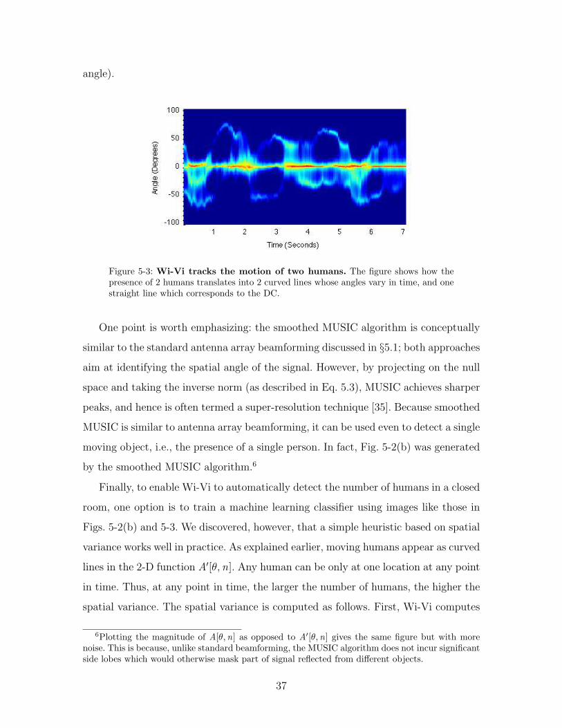
angle).
Figure 5-3: Wi-Vi tracks the motion of two humans. The figure shows how thepresence of 2 humans translates into 2 curved lines whose angles vary in time, and onestraight line which corresponds to the DC.
One point is worth emphasizing: the smoothed MUSIC algorithm is conceptually
similar to the standard antenna array beamforming discussed in §5.1; both approaches
aim at identifying the spatial angle of the signal. However, by projecting on the null
space and taking the inverse norm (as described in Eq. 5.3), MUSIC achieves sharper
peaks, and hence is often termed a super-resolution technique [35]. Because smoothed
MUSIC is similar to antenna array beamforming, it can be used even to detect a single
moving object, i.e., the presence of a single person. In fact, Fig. 5-2(b) was generated
by the smoothed MUSIC algorithm.6
Finally, to enable Wi-Vi to automatically detect the number of humans in a closed
room, one option is to train a machine learning classifier using images like those in
Figs. 5-2(b) and 5-3. We discovered, however, that a simple heuristic based on spatial
variance works well in practice. As explained earlier, moving humans appear as curved
lines in the 2-D function A′[θ, n]. Any human can be only at one location at any point
in time. Thus, at any point in time, the larger the number of humans, the higher the
spatial variance. The spatial variance is computed as follows. First, Wi-Vi computes
6Plotting the magnitude of A[θ,n] as opposed to A′[θ,n] gives the same figure but with morenoise. This is because, unlike standard beamforming, the MUSIC algorithm does not incur significantside lobes which would otherwise mask part of signal reflected from different objects.
37

the spatial centroid as a function of time:
C [n] =90∑
θ=−90
θ · 20 log10 A′[θ, n], (5.4)
where A′[θ, n] is given by Eq. 5.3. It then computes the spatial variance as:
VAR[n] =90∑
θ=−90
θ2 · 20 log10 A′[θ, n]− C [n]2 (5.5)
This variance is then averaged over the duration of the experiment to return one
number that describes the spatial variance in the room for the duration of the mea-
surement. Wi-Vi uses a training set and a testing set to learn the thresholds that
separate the spatial variances corresponding to 0, 1, 2, or 3 humans. The testing and
training experiments are conducted in different rooms. In §7.4, we evaluate this scheme
and measure its ability at automatically capture the number of moving humans.
38

Chapter 6
Through-Wall Gesture-Based
Communication
For a human to transmit a message to a computer wirelessly, she typically has to
carry a wireless device. In contrast, Wi-Vi can enable a human who does not carry
any wireless device to communicate commands or short messages to a receiver using
simple gestures. Wi-Vi designates a pair of gestures as a ‘0’ bit and a ‘1’ bit. A human
can compose these gestures to create messages that have different interpretations. Ad-
ditionally, Wi-Vi can evolve by borrowing other existing principles and practices from
today’s communication systems, such as adding a simple code to ensure reliability, or
reserving a certain pattern of ‘0’s and ‘1’s for packet preambles. At this stage, Wi-
Vi’s interface is still very basic, yet we believe that future advances in through-wall
technology can render this interface more expressive.
Below, we describe the gesture-based communication channel that we implemented
with Wi-Vi.
6.1 Gesture Encoding
At the transmitter side, the ‘0’ and ‘1’ bits must be encoded using some modulation
scheme. Wi-Vi implements this encoding using gestures. One can envision a wide
variety of gestures to represent these bits. However, in choosing our encoding we have
39

imposed three conditions: 1) the gestures must be composable – i.e. at the end of
each bit, whether ‘0’ or ‘1’, the human should be back in the same initial state as the
start of the gesture. This enables the person to compose multiple such gestures to
send a longer message. 2) The gestures must be simple so that a human finds it easy
to perform them and compose them. 3) The gestures should be easy to detect and
decode without requiring sophisticated decoders, such as machine learning classifiers.
Given the above constraints, we have selected the following gestures to modulate
the bits: a ‘0’ bit is a step forward followed by a step backward; a ‘1’ bit is a step
backward followed by a step forward. This modulation is similar to Manchester en-
coding, where a ‘0’ bit is represented by a falling edge of the clock, (i.e., an increase
in the signal value followed by a decrease,) and a ‘1’ bit is represented by a rising
edge of the clock, (i.e., a reduction in signal value followed by an increase) [2]. These
gestures are simple, composable and easy to decode as we show in §6.2.
Figure 6-1: Gestures as detected by Wi-Vi. The figure shows a sequence of fourgestures: step forward, step backward, step backward, step forward. Forward stepsappear as triangles above the zero line; backward steps appear as inverted trianglesbelow the zero line. Each pair of gestures represents a bit: the first two represent bit‘0’, the second two represent bit ‘1’.
Fig. 6-1 shows the signal captured by Wi-Vi, at the output of the smoothed
MUSIC algorithm for each of these two gestures. Taking a step forward towards the
Wi-Vi device produces a positive angle, whereas taking a step backward produces a
negative angle. The exact values of the produced angles depend on whether the human
is exactly oriented towards the device. Recall that the angle is between the vector
40

orthogonal to the motion and the line connecting the human to the Wi-Vi device,
and its sign is positive when the human is moving toward Wi-Vi and negative when
the human moves away from Wi-Vi. As shown in Fig. 6-2, if the human is directly
oriented towards the device, the two angles are +90◦ and -90◦. If the human does not
know the exact location of the Wi-Vi device and simply steps in its general direction,
the absolute value of the angle is smaller, but the shape of the bit is maintained.
!"#"$%
θ2=+90%
!"#"$%
θ1=-90%θ2=+60!
"#$#%!
(a) Forward (b) Backward (c) Slanted
Figure 6-2: Gestures as Angles. Recall θ’s magnitude and sign as defined in §5.1. In(a), the subject takes one step forward; the emulated antenna array’s normal forms anangle of 90◦ with the line from the human to Wi-Vi. Because the vector of the motionand the vector from the human to Wi-Vi are in same direction, θ is positive; hence,it is +90◦. In (b), the subject takes a step backward, and θ = −90 degrees. In (c),the subject does not exactly know where the Wi-Vi device is, so he performs the stepstowards the wall, without orienting himself directly toward Wi-Vi. Note that the vectorof motion and the vector from the human to Wi-Vi are in the same direction; hence, θis positive. However, due to the slanted orientation, it is now +60◦ (rather than +90◦).
6.2 Gesture Decoding
Decoding the above gestures is fairly simple and follows standard communication
techniques. Specifically, Wi-Vi’s decoder takes as input A′[θ, n]. Similar to a standard
decoder [17], Wi-Vi applies a matched filter on this signal. However, since each bit is a
combination of two steps, forward and backward, Wi-Vi applies two matched filters:
one for the step forward and one for the step backward. Because of the structure
of the signal shown in Fig. 6-1, the two matched filters are simply a triangle above
41

the zero line, and an inverted triangle below the zero line. Wi-Vi applies these filters
separately on the received signal, then adds up their output.
-1500-1000-500
0 500
1000 1500
0 2 4 6 8 10 12 14
Mat
ched
Out
put
Time (Seconds)
(a) Output of matched filter.
-1.5-1
-0.5 0
0.5 1
1.5
0 2 4 6 8 10 12 14
Map
ped
Sym
bols
Time (Seconds)
Bit ‘0’ Bit ‘1’
(b) Decoded bits.
Figure 6-3: Gesture Decoding in Wi-Vi. The figure shows how Wi-Vi decodesthe gestures of Fig. 6-1. (a) shows the output of the matched filter step. (b) showsthe output of the peak detector. The sequence (1,−1) represents bit ‘0’, whereas thesequence (−1, 1) represents bit ‘1’.
Fig. 6-3 shows the results of applying the matched filters on the received signal in
Fig. 6-1. Note that the signal after applying the matched filters looks fairly similar
to a BPSK signal, where a peak above the zero line represents a ‘1’ bit and a trough
below the zero line represents a ‘0’ bit. (Though in Wi-Vi our encoding is such that
a peak or a trough alone only represents half a bit.) Next, Wi-Vi uses a standard
peak detector to detect the peaks/troughs and match them to the corresponding
bits. Fig. 6-3 shows the the identified peaks and the detected bits for the two bit
message in Fig. 6-1.
42
Chapter 7
Implementation and Evaluation
In this chapter, we describe our implementation and the results of our experimental
evaluation.
7.1 Implementation
We built Wi-Vi using USRP N210 software radios [8] with SBX daughter boards.
The system uses LP0965 directional antennas [3], which provide a gain of 6 dBi.
The system consists of three USRPs connected to an external clock so that they
act as one MIMO system. Two of the USRPs are used for transmitting, and one
for receiving. MIMO nulling is implemented directly into the UHD driver, so that it
is performed in real-time. Post processing using the smoothed MUSIC algorithm is
performed on the obtained traces offline in Matlab R2012a under Ubuntu 11.10 on
a 64-bit machine with Intel i7 processor. Matlab already has a built-in and highly
optimized smoothed MUSIC implementation. Processing traces of 25-second length
took on average 1.0564s per trace, with a standard deviation of 0.2561s.
We implement standard Wi-Fi OFDM modulation in the UHD code; each OFDM
symbol consists of 64 subcarriers including the DC. The nulling procedure in §4
is performed on a subcarrier basis. The channel measurements across the different
subcarriers are combined to improve the SNR. Since USRPs cannot process signals
in real-time at 20 MHz, we reduced the transmitted signal bandwidth to 5 MHz so
43

that our nulling can still run in real time.
Finally, the emulated antenna array used in the smoothed MUSIC algorithm was
taken over 0.32 seconds. The collected samples during this duration were averaged into
an antenna array of size w = 100, which was provided as an input to the smoothed
MUSIC algorithm.
7.2 Experimental Setup
Our experiments were conducted in two buildings on the MIT campus. The first
building is a standard office building whose interior walls consist of 6” interior hollow
walls supported by steel frames with sheet rock on top. The second is an older building
with 8” concrete walls. Most of our experiments were run in the first building using
two different conference rooms. The rooms have standard furniture: tables, chairs,
boards, etc. The first conference room is 7× 4 meters; the second is 11× 7 meters.
The experiments were conducted with 8 human subjects, 3 women and 5 men, of
different heights and builds. For the tracking experiments, we asked the subjects to
enter a room, close the door, and move at will. The through-wall gesture experiments
were performed with 4 subjects out of the 8 (1 woman and 3 men). The persons were
shown the gestures in advance and allowed to try them a few times. Afterwards, each
of them entered the room separately and performed the gestures. The experiments
are repeated in different locations in different rooms, and in different locations in each
room.
7.3 Micro Benchmarks
First, we would like to get a better understanding of the information captured by Wi-
Vi, and how it relates to the moving objects. We run experiments in two conference
rooms in our building. Both conference rooms have 6” hollow walls supported by
steel frames with sheet rock on top. In all of these experiments, we position Wi-Vi
one meter away from a wall that has neither a door nor a window. For each of our
44

experiments, we ask a number of humans between 1 and 3 to enter the room, close
the door, and move at will. Wi-Vi performs nulling in real time and collects a trace
of the signals. We perform each experiment with a different subset of our subjects.
We process the collected traces using the smoothed MUSIC algorithm as described
in §5.2.
Fig. 7-1 shows the output of Wi-Vi in the presence of one, two, or three humans
moving in a closed room. Consider the plots with one human in Figs. 7-1(a). Besides
the DC, the graphs show one fuzzy curved line. The line tracks the spatial angle of
the moving human. Compare these figures with the set of figures in 7-1(b), which
capture two moving humans. In 7-1(b), we can discern two curved lines that track
the angular motion of these humans with respect to Wi-Vi. If we take a vertical line
at any time, in any of the two-human figures, we see at most two bright lines, besides
the DC. This is because, in these figures, at any point in time, there are at most two
moving bodies in the room. Let us zoom in on the interval [1s , 2s ] in 7-1(b1). During
this interval, we see only one curved line. This has two possible interpretations: either
one of the two people stopped moving or he/she was too deep inside the room that we
could not capture his/her signal. As we move to 7-1(c), the figures get fuzzier since
we have more people moving in the same area. However the general observations
carry to these figures. Specifically, we can identify the presence of three humans from
observing multiple intervals in which we can discern three curved lines. For example,
consider the interval [1.8s , 2.5s ] in 7-1(c1), which shows two lines with positive angles
and one line with a negative angle. These lines indicate that two people are moving
towards Wi-Vi, while one person is moving away.
One can also make multiple observations based on the shape of the lines. First,
a positive angle means the human is moving toward Wi-Vi, while a negative angle
means that he is moving away. The value of that angle depends on the orientation of
the human and the direction of motion. Each line looks like a wave because, given a
confined space, a person that moves towards Wi-Vi will eventually have to move away
or stop. Second, the brightness of the line typically indicates distance. Note that for
the same spatial angle, one may be close or far from Wi-Vi. Hence, some large angles
45

0 1 2 3 4 5 6 7Time (seconds)
-100
-80
-60
-40
-20
0
20
40
60
80
100
Ang
le (
degr
ees)
1
1
0 1 2 3 4 5 6 7Time (seconds)
-100
-80
-60
-40
-20
0
20
40
60
80
100
Ang
le (
degr
ees)
1
2
1
0 1 2 3 4 5 6 7Time (seconds)
-100
-80
-60
-40
-20
0
20
40
60
80
100
Ang
le (
degr
ees)
12
3
(a1) (b1) (c1)
0 1 2 3 4 5 6 7Time (seconds)
-100
-80
-60
-40
-20
0
20
40
60
80
100
Ang
le (
degr
ees)
0 1 2 3 4 5 6 7Time (seconds)
-100
-80
-60
-40
-20
0
20
40
60
80
100
Ang
le (
degr
ees)
1
2
0 1 2 3 4 5 6 7Time (seconds)
-100
-80
-60
-40
-20
0
20
40
60
80
100
Ang
le (
degr
ees)
1
2 3
(a2) (b2) (c2)
0 1 2 3 4 5 6 7Time (seconds)
-100
-80
-60
-40
-20
0
20
40
60
80
100
Ang
le (
degr
ees)
0 1 2 3 4 5 6 7Time (seconds)
-100
-80
-60
-40
-20
0
20
40
60
80
100
Ang
le (
degr
ees)
1
2
0 1 2 3 4 5 6 7Time (seconds)
-100
-80
-60
-40
-20
0
20
40
60
80
100
Ang
le (
degr
ees)
1
2
3
(a3) (b3) (c3)
(a) One Human (b) Two Humans (c) Three Humans
Figure 7-1: Tracking human motion with Wi-Vi. The figures show output traceswith a different number of humans after processing with the smoothed MUSIC algo-rithm. They plot A′[θ,n] where θ is the angle in [−90, 90] is plotted on the y-axis andtime is on the x-axis. (a) shows traces for one human; (b) for two humans; and (c) forthree humans moving behind the wall of a closed room.
46

appear bright or dim depending on the part of the trace we look at.
A third observation is that as the number of humans increases, it becomes harder
to separate them. The problem is that the curved lines are fuzzy both due to residual
noise as well as the fact that a human can move his body parts differently as he moves.
For example, waving while moving makes the lines significantly fuzzier as in 7-1(a3).
Finally, our experiments are conducted in multipath-rich indoor environments.
Thus, the results in Fig. 7-1 show that Wi-Vi works in the presence of multipath
effects. This is because the direct path from a moving human to Wi-Vi is much
stronger than indirect paths which bounce off the internal walls of the room. A moving
human acts like a large antenna. In order to block the direct path, the human body
must be obstructed by a pillar or a large piece of furniture, and stay obstructed for
the duration of Wi-Vi’s measurements.1
7.4 Automatic Detection of Moving Humans
We are interested in evaluating whether Wi-Vi can use the spatial variance described
in §5.2 to automate the detection of moving humans. As in the previous section,
we run our experiments in the same conference rooms described in §7.3. Again, we
position Wi-Vi such that it faces a wall that has neither a door nor a window. For
each of our experiments, we ask a number of humans between 0 and 3 from our
volunteers to enter the room and move at will. Each experiment lasts for 25 seconds
excluding the time required for iterative nulling. We perform each experiment with a
different subset of subjects, and conduct a total of 80 experiments, with equal number
of experiments spanning the cases of 0, 1, 2, and 3 moving humans. We process the
collected traces offline and compute the spatial variance as described in §5.2.
Fig. 7-2 shows the CDFs (cumulative distribution functions) of the spatial variance
for the experiments run with each number of moving humans: 0, 1, 2, and 3. The figure
1We also conducted experiments where part of the wall has a glass door, which enables someof the indirect reflections to escape the closed room at a lower attenuation. We did not observequalitative difference in the results. We believe the reason is that indirect signals that bounce off amoving human then bounce off some additional object are too weak and arrive at an angle outsidethe field of view of our directional antennas.
47

allows us to make the following observations:
• The spatial variance provides a good metric for distinguishing the number of
moving humans. In particular, the variance increases as the number of humans
involved in each experiment increases. This is also evident from the figures
in 7-1, where one can visually see that the spatial variance is higher with more
moving bodies in the room.
• Interestingly, the separation between successive CDFs decreases as the number
of humans increases. In particular, the separation is larger between the CDFs
of no humans and one human, than between the CDFs of one human and two
humans. The separation is the least between the CDFs of 2 humans and 3. To
understand this behavior, recall that because the room has a confined space,
as the number of people increases, the freedom of movement decreases. Hence,
adding a human to a congested space is expected to add less spatial variance
than adding her to a less congested space where she has more freedom to move.
0
0.2
0.4
0.6
0.8
1
0 1 2 3 4 5
Fra
ctio
n of
exp
erim
ents
Spatial Variance of the MUSIC image (in tens of millions)
No humansOne human
Two humansThree humans
Figure 7-2: CDF of spatial variance for a different number of moving humans.As the number of humans increases, the spatial variance increases.
Next, we would like to automate the thresholds for distinguishing 0, 1, 2, and 3
moving humans. To do so, we divide the data into a training set and a testing set.
To ensure that Wi-Vi can generalize across environments, we ensure that the training
examples are all conducted in one conference room, while the testing examples are
48

conducted in another conference room (Recall that the two rooms have different
sizes). We use the training set to learn the thresholds to separate the spatial variances
corresponding to 0, 1, 2, and 3 humans. We then use these thresholds to classify the
experiments in the testing set. Finally, we perform cross-validation, i.e., we repeat
the same procedure after switching the training and testing sets.
Table 7.1 shows the result of the classification. The table shows that Wi-Vi can
identify whether there is 0 or 1 person in a room with 100% accuracy; this is expected
based on the CDFs in Fig. 7-2. Furthermore, row 3 shows that two humans are never
confused with 0 or 1. However, Wi-Vi confused 2 humans with 3 humans in 15% of
the trials, whereas it accurately identified their number in 85% of the cases.
❍❍
❍❍❍
❍❍❍❍
Actual
Detected0 1 2 3
0 100% 0% 0% 0%
1 0% 100% 0% 0%
2 0% 0% 85% 15%
3 0% 0% 10% 90%
Table 7.1: Accuracy of Automatic Detection of Humans. The table shows theaccuracy of detecting the number of moving humans based on the spatial variance.
7.5 Gesture Decoding
Next, we evaluate Wi-Vi’s ability to decode the bits associated with the gestures in §6.
In each experiment, a human is asked to stand at a particular distance from the wall
that separates the room from our device, and perform the two gestures corresponding
to bit ‘0’ and bit ‘1’. Each human took steps at a length they found comfortable.
Typical step sizes were 2-3 feet. The experiments are repeated at various distances
in the range [1m, 9m]. All experiments are conducted in the same conference rooms
described above and under the same experimental conditions. One of our conference
rooms is only 7m wide, whereas the other is 11m wide. Hence, the experiments with
49

distances larger than 6 meters are conducted in the larger conference room, whereas
for all distances less than or equal 6 meters, our experiments included trials from
both rooms. The obtained traces are processed using the matched filter and decoding
algorithm described in §6.2.
Fig. 7-3 plots the fraction of time the gestures were decoded correctly as a function
of the distance from the wall separating Wi-Vi from the closed room. We note the
following observations:
• Wi-Vi correctly decoded the performed gestures at all distances less than or
equal to 5m. It identified 93.75% of the gestures performed at distances between
6m and 7m. At 8m, the performance started degrading, leading to correct iden-
tification of only 75% of the gestures. Finally, Wi-Vi could not identify any of
the gestures when the person was standing 9m away from the wall.
• It is important to note that, in our experiments, Wi-Vi never mistook a ‘0’
bit for a ‘1’ bit or the inverse. When it failed to decode a bit, it was because
it could not register enough energy to detect the gesture from the noise. This
means that Wi-Vi ’s errors are erasure errors as opposed to standard bit errors.
• We measured the time it took the different subjects to perform a one bit gesture.
Averaged over all traces, our subjects took 2.2s to perform a gesture, with a
standard deviation of 0.4s.
To gain further insight into Wi-Vi’s gesture decoding, Fig. 7-4 plots the CDFs of
the SNRs of the ‘0’ gesture and the ‘1’ gesture, across the experiments. Interestingly,
the gesture associated with a ‘0’ bit has a higher SNR than the gesture associated
with a ‘1’ bit. This is due to two reasons: First, the ‘0’ gesture involves a step forward
followed by a step backward, whereas the ‘1’ gesture requires the human to first step
backward then forward. Hence, for the same starting point, the human is on average
closer to Wi-Vi while performing the ‘0’ gesture, which results in an increase in the
received power. Second, taking a step backward is naturally harder for humans; hence,
they tend to take smaller steps in the ‘1’ gesture. This observation is visually evident
in Fig. 6-1 where a ‘0’ gesture has a higher power (red) than the ‘1’ gesture.
50

Per
cent
age
of c
orre
ct d
etec
tion
Distance (in m)
75
Bit ’0’100 100 100 100 100 100 100
75
0
Bit ’1’
0
20
40
60
80
100
1 2 3 4 5 6 7 8 9
Figure 7-3:Accuracy of Gesture Decoding as a Function of Distance. The figureshows the fraction of experiments in which Wi-Vi correctly decoded the bit associatedwith the performed gesture at different distances separating the subject from the wall.Note that Wi-Vi decodes a gesture only when its SNR is greater than 3dB; this explainsthe sharp cutoff between 8 and 9 meters.
We note that the main factor limiting gesture decodability with increased distance
is the low transmit power of USRPs. The linear transmit power range for USRPs is
around 20 mW (i.e., beyond this power the signal starts being clipped), whereas
Wi-Fi’s power limit is 100mW. Hence, one would expect that with better hardware,
Wi-Vi can have a higher decoding range.
7.6 The Effect of Building Material
Finally, we evaluate Wi-Vi’s performance with different building materials. Thus,
in addition to the two conference rooms described before, we also test Wi-Vi in a
second building in our university campus, where the walls are different. In particular,
we experiment with 4 types of building materials: 8” concrete wall, 6” hollow wall
supported by steel frames with sheet rock on top, 1.75” solid wood door, and tinted
glass. In addition, we perform experiments in free space with no obstruction between
Wi-Vi and the subject.
In each experiment, the subject is asked to stand 3 meters away from the wall (or
Wi-Vi itself in the case of no obstruction) and perform the ‘0’ bit gesture described
above. For each type of building material, we perform 8 experiments.
Fig. 7-5 shows Wi-Vi’s performance across the different building materials. Specif-
51

0
0.2
0.4
0.6
0.8
1
0 5 10 15 20 25 30
Fra
ctio
n of
exp
erim
ents
SNR of Gestures (in dB)
Bit ’0’Bit ’1’
Figure 7-4: CDF of the gesture SNRs. The figure shows the CDFs of the SNR afterapplying the matched filter taken over different distances from Wi-Vi.
ically, Fig. 7-5(a) shows the detection rate as the fraction of experiments in which
Wi-Vi correctly decoded the gesture, whereas Fig. 7-5(b) shows the average SNRs of
the gestures. The figures show that Wi-Vi can successfully detect humans and identify
their gestures across various indoor building materials: tinted glass, solid wood doors,
6” hollow walls, and to a large extent 8” concrete walls. As expected, the thicker and
denser the obstructing material, the harder it is for Wi-Vi to capture reflections from
behind it.
Detecting humans behind different materials depends on Wi-Vi’s power as well as
its ability to eliminate the flash effect. Fig. 7-6 plots the CDF of the amount of nulling
(i.e., reduction in SNRs) that Wi-Vi achieves in various experiments. The plot shows
Wi-Vi’s nulling reduces the signal from static objects by a median of 40 dB. This
number indicates that Wi-Vi can eliminate the flash reflected off common building
material such as glass, solid wood doors, interior walls, and concrete walls with a
limited thickness [1]. However, it would not be able to see through denser material
like re-enforced concrete. To improve the nulling, one may use a circulator at the
analog front end [19] or leverage recent advances in full-duplex radio [15], which were
reported to produce 80 dB reduction in interference power [20].
52

Per
cent
age
of c
orre
ct d
etec
tion 100 100 100 100
87.5
0
20
40
60
80
100
FreeSpace
TintedGlass
1.75" SolidWood Door
6" HollowWall
8" Concrete
(a) Detection Accuracy
SN
R (
in d
B)
0
5
10
15
20
25
30
35
FreeSpace
TintedGlass
1.75" SolidWood Door
6" HollowWall
8" Concrete
(b) SNR
Figure 7-5: Gesture detection in different building structures. (a) plots thedetection accuracy of Wi-Vi for different types of obstructions. (b) shows the averageSNR of the experiments done through these different materials, with the error barsshowing the minimum and maximum achieved SNRs across the trials.
0
0.2
0.4
0.6
0.8
1
0 10 20 30 40 50 60
Frac
tion
of e
xper
imen
ts
Nulling (in dB)
Figure 7-6: CDF of achieved nulling. The figure plots the CDF which shows theability of nulling to reduce the power received along static paths.
53

54

Chapter 8
Conclusion
There is a single light of science, and to brighten it anywhere is to brighten it
everywhere.
Isaac Asimov, Science Fiction Writer
This thesis presents Wi-Vi, a wireless technology which uses Wi-Fi signals to
detect moving humans behind walls and in closed rooms. In contrast to previous
systems which are targeted for the military, Wi-Vi enables small cheap see-through-
wall devices that operate in the ISM band, rendering them feasible to the general
public. Wi-Vi also establishes a communication channel between itself and a human
behind a wall, allowing him/her to communicate directly with Wi-Vi without carrying
any transmitting device.
We believe that Wi-Vi is an instance of a broader set of functionality that fu-
ture wireless networks will provide. Future Wi-Fi networks will likely expand beyond
communications and deliver services such as indoor localization, sensing, and control.
Wi-Vi demonstrates an advanced form of Wi-Fi-based sensing and localization by
using Wi-Fi to track humans behind wall, even when they do not carry a wireless
device. It also raises issues of importance to the networking community pertinent to
user privacy and regulations concerning the use of Wi-Fi signals.
Finally, Wi-Vi bridges state-of-the-art networking techniques with human-computer
interaction. It motivates a new form of user interfaces which rely solely on using the
55

reflections of a transmitted RF signal to identify human gestures. We envision that
by leveraging finer nulling techniques and employing better hardware, the system can
evolve to seeing humans through denser building material and with a longer range.
These improvements will further allow Wi-Vi to capture higher quality images en-
abling the gesture-based interface to become more expressive, hence promising new
directions for virtual reality.
56

Appendix
Convergence of Iterative Nulling
We prove why iterative nulling proposed in §4 converges. Wi-Vi models the channel
estimate errors as additive (in line with common practice of modeling quantization
error [26]). Hence, by substituting h1 with h1 +∆1, and h2 with h2 +∆2, in Eq. 4.1,
we obtain:
hres = h1 + h2
(
−h1 +∆1
h2 +∆2
)
≈h1h2∆2 −∆1 +
∆1∆2
h2(1)
which follows from the first order Taylor series approximation of 11−x
since ∆2 << h2.
Iterating on h1 alone. We first analyze how the algorithm converges if it were
iterating only on Step 1. According to Algorithm 1, h1 is refined to hres + h1. By
updating the precoding vector, the new received channel after nulling h ′
res is hres∆2
h2
by applying the first order Taylor series approximation of 11+∆2/h2
since ∆2 << h2.
Hence, |h ′
res | << |hres |. Therefore, after the i -th iteration, h(i)res becomes h
(0)res
(
∆2
h2
)i
.
Iterating on h2 alone. We now analyze how the algorithm converges if it were
iterating only on Step 2. According to Algorithm 1, h2 is refined to(
1− hres
h1
)
h2. By
updating the precoding vector, the new received channel after nulling is:
h ′
res ≈ h1 −h1
h2h2
(
1 +hres
h1
)
= hres∆2
h2(2)
which follows from the first order Taylor series approximation of 1
1−hres/h1since hnulling <<
h1. Hence, |h′
res | << |hres |, and h(i)res converges as above.
Iterative nulling on h1 and h2. By the above arguments, after i iterations on h1
57

and j iterations on h2, the nulled channel becomes:
h(i ,j )res = h(0)
res
(
∆2
h2
)i+j
(3)
58

Bibliography
[1] How Signal is affected. www.ci.cumberland.md.us/. City of Cumberland Re-
port.
[2] LAN/MAN CSMA/CDE (ethernet) access method. IEEE Std. 802.3-2008.
[3] LP0965. http://www.ettus.com. Ettus Inc.
[4] Nintendo Wii. http://www.nintendo.com/wii.
[5] RadarVision. http://www.timedomain.com. Time Domain Corporation.
[6] Seeing through walls - MIT’s Lincoln Laboratory.
http://www.youtube.com/watch?v=H5xmo7iJ7KA.
[7] Urban Eyes. https://www.llnl.gov. lawrence livermore national laboratory.
[8] USRP N210. http://www.ettus.com. Ettus Inc.
[9] Wi-Vi demo. https://people.csail.mit.edu/fadel/wivi. Massachusetts In-
stitute of Technology.
[10] X-box Kinect. http://www.xbox.com. Microsoft.
[11] R.W. Bohannon. Comfortable and maximum walking speed of adults aged 20-79
years: reference values and determinants. Age and ageing, 1997.
[12] G.L. Charvat, L.C. Kempel, E.J. Rothwell, C. Coleman, and EJ Mokole. An
ultrawideband (UWB) switched-antenna-array radar imaging system. In IEEE
ARRAY, 2010.
59

[13] G.L. Charvat, L.C. Kempel, E.J. Rothwell, C.M. Coleman, and E.L. Mokole. A
through-dielectric radar imaging system. IEEE Trans. Antennas and Propaga-
tion, 2010.
[14] K. Chetty, G.E. Smith, and K. Woodbridge. Through-the-wall sensing of per-
sonnel using passive bistatic wifi radar at standoff distances. IEEE Trans. Geo-
science and Remote Sensing, 2012.
[15] J.I. Choi, M. Jain, K. Srinivasan, P. Levis, and S. Katti. Achieving single channel,
full duplex wireless communication. In ACM MobiCom, 2010.
[16] G. Cohn, D. Morris, S. Patel, and D. Tan. Humantenna: using the body as an
antenna for real-time whole-body interaction. In ACM CHI, 2012.
[17] T.M. Cover and J.A. Thomas. Elements of information theory. Wiley-
interscience, 2006.
[18] S. Gollakota, F. Adib, D. Katabi, and S. Seshan. Clearing the RF smog: Making
802.11 robust to cross-technology interference. In ACM SIGCOMM, 2011.
[19] S. Hong, J. Mehlman, and S. Katti. Picasso: full duplex signal shaping to exploit
fragmented spectrum. In ACM SIGCOMM, 2012.
[20] M. Jain, J.I. Choi, T. Kim, D. Bharadia, S. Seth, K. Srinivasan, P. Levis, S. Katti,
and P. Sinha. Practical, real-time, full duplex wireless. In ACM MobiCom, 2011.
[21] H. Junker, P. Lukowicz, and G. Troster. Continuous recognition of arm activities
with body-worn inertial sensors. In IEEE ISWC, 2004.
[22] Y. Kim and H. Ling. Human activity classification based on micro-doppler sig-
natures using a support vector machine. IEEE Trans. Geoscience and Remote
Sensing, 2009.
[23] K.C.J. Lin, S. Gollakota, and D. Katabi. Random access heterogeneous MIMO
networks. In ACM SIGCOMM, 2010.
60

[24] B. Lyonnet, C. Ioana, and M.G. Amin. Human gait classification using mi-
crodoppler time-frequency signal representations. In IEEE Radar Conference,
2010.
[25] B. Michoud, E. Guillou, and S. Bouakaz. Real-time and markerless 3D human
motion capture using multiple views. Human Motion–Understanding, Modeling,
Capture and Animation, 2007.
[26] A.V. Oppenheim, R.W. Schafer, J.R. Buck, et al. Discrete-time signal processing.
Prentice hall Englewood Cliffs, NJ:, 1989.
[27] H.S. Rahul, S. Kumar, and D. Katabi. JMB: scaling wireless capacity with user
demands. In ACM SIGCOMM, 2012.
[28] T.S. Ralston, G.L. Charvat, and J.E. Peabody. Real-time through-wall imaging
using an ultrawideband multiple-input multiple-output (MIMO) phased array
radar system. In IEEE ARRAY, 2010.
[29] S.S. Ram, C. Christianson, Y. Kim, and H. Ling. Simulation and analysis of
human micro-dopplers in through-wall environments. IEEE Trans. Geoscience
and Remote Sensing, 2010.
[30] S.S. Ram, Y. Li, A. Lin, and H. Ling. Doppler-based detection and tracking of
humans in indoor environments. Journal of the Franklin Institute, 2008.
[31] S.S. Ram and H. Ling. Through-wall tracking of human movers using joint
doppler and array processing. IEEE Geoscience and Remote Sensing Letters,
2008.
[32] Tie-Jun Shan, M. Wax, and T. Kailath. On spatial smoothing for direction-of-
arrival estimation of coherent signals. IEEE Trans. on Acoustics, Speech and
Signal Processing, 1985.
[33] F. Soldovieri and R. Solimene. Through-wall imaging via a linear inverse scat-
tering algorithm. IEEE Geoscience and Remote Sensing Letters, 2007.
61

[34] R. Solimene, F. Soldovieri, G. Prisco, and R. Pierri. Three-dimensional through-
wall imaging under ambiguous wall parameters. IEEE Trans. Geoscience and
Remote Sensing, 2009.
[35] Petre Stoica and Randolph L. Moses. Spectral Analysis of Signals. Prentice Hall,
2005.
[36] William C. Stone. Nist construction automation program report no. 3: Electro-
magnetic signal attenuation in construction materials. In NIST Construction
Automation Workshop 1995.
[37] Kun Tan, He Liu, Ji Fang, Wei Wang, Jiansong Zhang, Mi Chen, and Geoffrey
Voelker. SAM: Enabling Practical Spatial Multiple Access in Wireless LAN. In
ACM MobiCom, 2009.
[38] DJ Titman. Applications of thermography in non-destructive testing of struc-
tures. NDT & E International, 2001.
[39] H. Wang, R.M. Narayanan, and Z.O. Zhou. Through-wall imaging of moving
targets using uwb random noise radar. IEEE Antennas and Wireless Propagation
Letters, 2009.
[40] Jie Xiong and Kyle Jamieson. ArrayTrack: a fine-grained indoor location system.
In Usenix NSDI, 2013.
[41] Y. Yang and A. Fathy. Design and implementation of a low-cost real-time ultra-
wide band see-through-wall imaging radar system. In IEEE/MTT-S Interna-
tional Microwave Symposium, 2007.
[42] Y. Yang and A.E. Fathy. See-through-wall imaging using ultra wideband short-
pulse radar system. In IEEE Antennas and Propagation Society International
Symposium, 2005.
62