Embed Size (px)
Citation preview

Security TechnologyKNX-Intrusion Alarm System L240Installation, Commissioning, Operation

Contents
3
Contents Page
1 Intrusion Alarm System L240 7 1.1 General description 7 1.2 Degree of expansion 7 1.3 System components 8 1.4 System overview 9
2 Installation Instructions 10 2.1 General explanations 10 2.2 Wiring 10 2.3 Required components to an entry (door) 11
3 Intrusion Alarm Panel L240 12 3.1 General 12 3.2 Installation 13 3.3 Connections and technical data 14 3.4 Description of the inputs and outputs 16
4 Commissioning 18 4.1 Basic expansion 18 4.2 Direct connection of the inputs and outputs 18 4.3 External connection of the inputs and outputs 19 4.4 Expansion of the panel with bus nodes 20
5 Keypad L240/PT 22 5.1 General description 22 5.2 Connection 23
6 Operation with Keypad L240/PT 24 6.1 General information 24 6.2 Operation without PIN code (access level 0) 26
6.2.1 Button 1 “Int Set” 26 6.2.2 Button 2 “Cct Off” 26 6.2.3 Button 3 “Disp Cct Off” 27 6.2.4 Button 4 “Input PIN” 27 6.2.5 Button 5 “Disp Cct Fault” 27
6.3 Operation with PIN code (access level 1) 28 6.3.1 Menu 01 “Int Set” 29 6.3.2 Menu 02 “Cct Off” 29 6.3.3 Menu 03 “Disp Cct Off” 29 6.3.4 Menu 04 “Change PIN” 29 6.3.5 Menu 05 “Disp Cct Fault” 30 6.3.6 Menu 06 “Test” 30 6.3.7 Menu 07 “Alarm Counter” 30 6.3.8 Menu 08 “Log” 31 6.3.9 Menu 09 “Ext Set” 33 6.3.10 Menu 10 “Time/Date” 33 6.3.11 Menu 11 “Log Eng On” 34 6.3.12 Menu 12 “Tamp.Reset” 34
Contents
4
7 Operation by the Engineer 35 7.1 Functions 35
7.1.1 Menu 1 “Time/Date” 36 7.1.2 Menu 2 “Tamp.Reset” 36 7.1.3 Menu 3 “Test” 36 7.1.4 Menu 04 “Change PIN” 38 7.1.5 Menu 5 “Printer” 39 7.1.6 Menu 6 “Printer” 40 7.1.7 Menu 7 “Remote” 41 7.1.8 Menu 8 “Edit” 43 7.1.9 Menu 9 “Cct Off” 43
8 Configuration and programming 44 8.1 Overview 44
8.1.1 Menu 01 “System Size” 46 8.1.2 Menu 02 “Area Opts” 47 8.1.3 Menu 03 “Circuits” 50 8.1.4 Menu 04 “Relay” 58 8.1.5 Menu 05 “Alarm Times” 59 8.1.6 Menu 06 “Keypads” 60 8.1.7 Menu 07 “Concs” 60 8.1.8 Menu 08 “User Auth” 61 8.1.9 Menu 09 “Text” 61 8.1.10 Menu 10 “L240/B/BS” 62 8.1.11 Menu 11 “XS/S1.1 KNX” 62 8.1.12 Menu 13 “2-Conc Tamper” 63 8.1.13 Menu 15 “Defaults” 63 8.1.14 Menu 16 “XIB-Detectors” 64
9 Management of the chip key/keypad code 65
9.1 General 65 9.2 Operating menu 66
9.2.1 Menu 06 – Add 66 9.2.2 Menu 05 – Text 67 9.2.3 Menu 01 – Edit 67 9.2.4 Menu 02 – Show (Key/Code) 68 9.2.5 Menu 02 – Show (L240/BS) 68 9.2.6 Menu 04 – Delete 69 9.2.7 Menu 03 – Identify 70 9.2.8 Exiting management 70
10 2-Detector Circuit Module L240/MG 2 71 10.1 General notes 71 10.2 Circuit diagram 71 10.3 Description of the inputs and outputs 72 10.4 Addressing 72 10.5 Commissioning 73 10.6 Address table L240/MG 2 and L840/MG 4 75 10.7 Technical data 75

Contents
5
11 4-Detector circuit module L840/MG 4 76 11.1 General 76 11.2 Circuit diagram 76 11.3 Description of the inputs and outputs 76 11.4 DIP switch/jumper settings: 77 11.5 Addressing 77 11.6 Commissioning 77
12 SafeKey Evaluation Module L240/BS 79 12.1 General 79 12.2 Wiring 80
12.2.1 Magnetic reed contact 80 12.2.2 Lock bolt switching contact 80 12.2.3 Bolt lock 81 12.2.4 XIB security bus 81 12.2.5 Cover tamper contact 82 12.2.6 Wall reader 82 12.2.7 Transistor outputs 83
12.3 Description of the inputs and outputs 84 12.4 LEDs 85
12.4.1 Light emitting diode “LED1” (red) 85 12.4.2 Light emitting diode “LED2” (green) 85 12.4.3 Light emitting diode “LED3” (red) 85
12.5 DIP switch blocks 85 12.5.1 Function switch 1 86 12.5.2 Function switch 2 86 12.5.3 Address switch 87
12.6 Commissioning 88 12.7 Operation 91
12.7.1 SET circuit 92 12.7.2 Access and UNSET switching 92 12.7.3 Access 94 12.7.4 Personal attack 94
13 Bus Motion Detector 95 13.1 General notes 95 13.2 Circuit diagram 95 13.3 Description of the LEDs 96 13.4 Commissioning and addressing 96 13.5 Teaching in the first detector 97
13.5.1 Teaching-in further detectors 98 13.6 Parameter settings 99 13.7 Walk test 100 13.8 Delete 100 13.9 Faults 101 13.10 VdS operation 101
Contents
6
14 Interface Module L208/V.24 102 14.1 General 102 14.2 Circuit diagram 102 14.3 Login 103 14.4 Serial connection 103 14.5 Setting the interface parameters 103
15 LAN Interface L240/IP 104 15.1 General 104 15.2 Circuit diagram 105 15.3 Commissioning 105 15.4 Setting the IP address of the PC 105 15.5 Setting the network parameters on the L240 106
Appendix
Overview User / Programming Menu L240 A Programming Example B System Protocol C

General Description
7
1 Intrusion Alarm System L240 1.1 General
description The Intrusion Alarm Panel L240 is a compact emergency signalling centre, which uses the same base device, and depending on the connected bus nodes complies with the guidelines of the VdS for class A, B or C, as well as the standards DIN/VDE 0100, 0800 and 0833. The unit is also CE compliant.The panel is a black-box device without installed keypads and displays; operation is generally undertaken using seven separate keypads.
1.2 Degree of expansion In its basic configuration, the panel features 10 inputs, which are suitable
both for the connection of sensors (detector groups) as well as for a setting device. In order to expand the panel with bus devices, an LCD Keypad L240/PT that can also be used for programming the panel is absolutely necessary. As an option, the panel can be expanded by up to 4 setting areas. The switching devices are then connected to bus modules: Up to 8 Evaluation Modules L240/BS can be used for the SafeKey components, whereby both the key management as well as the access memory can be handled via the panel. On the detector circuit side, the panel can be expanded via bus modules: Up to 40 motion detectors, up to 24 Detector Circuit Modules L840/MG4 or L240/MG2 (can be combined) (1). The enclosure offers space for the installation of 2 batteries 12 V/7 Ah and the telephone dialling devices TSQ8, TS9S/L2 (2) or TS9/ISDN-L2 (2). The panel is delivered with basic programming features that can be used to immediately commission the device. Should individual functions be reprogrammed or further components connected and enabled, this can be undertaken via a keypad that has to be permanently connected or just connected for the duration of programming. Alternatively, the programming of the panel can also be undertaken with the PC and the programming software WIN-PC. (1)
Regarding the number of Detector Circuit Modules L240/MG2 or L840/MG4 and bus modules, it is important to observe that the total number of detector circuits does not exceed 80 (incl. the 10 circuits for the panel).
(2)
For Germany only
General Description
8
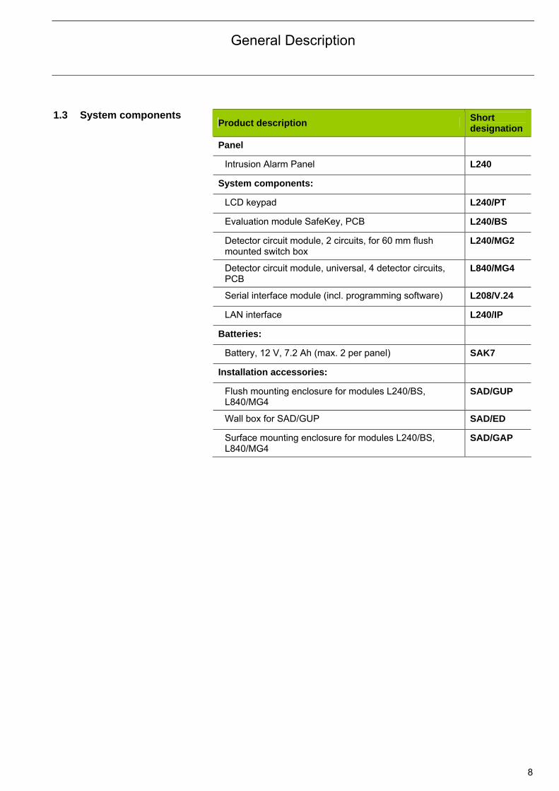
1.3 System components
Product description Short designation
Panel
Intrusion Alarm Panel L240
System components:
LCD keypad L240/PT
Evaluation module SafeKey, PCB L240/BS
Detector circuit module, 2 circuits, for 60 mm flush mounted switch box
L240/MG2
Detector circuit module, universal, 4 detector circuits, PCB
L840/MG4
Serial interface module (incl. programming software) L208/V.24
LAN interface L240/IP
Batteries:
Battery, 12 V, 7.2 Ah (max. 2 per panel) SAK7
Installation accessories:
Flush mounting enclosure for modules L240/BS, L840/MG4
SAD/GUP
Wall box for SAD/GUP SAD/ED
Surface mounting enclosure for modules L240/BS, L840/MG4
SAD/GAP

General Description
9
1.4 System overview
L24
0/P
T K
eyp
ad
Ope
ratio
n, p
rogr
amm
ing
and
disp
lay
of a
ll fu
nctio
ns
in a
ran
ge. I
n to
tal 7
ke
ypad
s (a
ddre
sses
1-7
) ar
e pe
rmis
sibl
e. A
t le
ast
one
keyp
ad is
re
quire
d p
er a
rea.
.
L24
0/M
G2
2
circ
uits
with
ter
min
atio
n re
sist
or.
Sui
tabl
e fo
r gl
ass
bre
ak a
nd m
agn
etic
cont
acts
(S
PG
S/W
, M
RS
/W,
SW
M4)
. In
stal
latio
n in
60
mm
FM
soc
ket.
Max
. 24
devi
ces
(ad
dres
ses
1-24
).
MR
S/W
M
ag
netic
re
ed
cont
act
SP
G S
/W
Gla
ss b
rea
k se
nsor
SW
M4
Wa
ter
sens
or
SG
L
Ga
s se
nso
r O
RM
1003
O
ptii
cal s
mok
e d
ete
cto
r
E10
00B
RE
L
12N
L
So
cke
t fo
r sm
oke
de
tect
or
ND
/W
Pa
nic
bu
tton
L24
0/IR
-XB
M
otio
n D
etec
tor
Mod
ule
SS
F/G
B
Ext
ern
al s
iren
SS
S
Inte
rna
l sire
n
Intr
usio
n A
larm
Pan
el L
240
P
ower
sup
ply
for
2 *
7.2
Ah,
10
pre
prog
ram
med
circ
uits
,
2 bu
s te
rmin
atio
ns,
8 tr
ansi
stor
ou
tput
s,
3 re
lays
(al
arm
, se
t, w
alk
test
) A
lert
ing
and
com
m s
igna
ls,
4 ar
eas
No
te:
In
tota
l 80
circ
uits
may
not
be
exce
eded
. E
xam
ple
: int
rusi
on a
larm
pan
el 1
0 cc
ts, 1
0*L2
40/M
G2
(20
ccts
), 5
*L2
40/IR
-XB
(5
ccts
): to
tal 3
5.
ES
PE
B
olt
lock
W
RK
/W
Bol
t sw
itch
ing
cont
act
MR
S/W
M
agen
tic r
eed
cont
act
WE
L/A
S
afe
Ke
y w
all
read
er
WE
LT
S
afe
Ke
y w
all
read
er
For
con
nec
tion
of o
ne
PC
with
sof
twar
e W
IN-P
C.
Max
. 1 m
odul
e op
tiona
l L2
08/V
.24
or L
240
/IP
can
be
con
nect
ed
L20
8/V
.24
Se
ria
l int
erfa
ce
L24
0/IP
L
AN
inte
rfa
ce
L24
0/B
S
Saf
eKe
y ev
alua
tion
mod
ule,
fo
r co
nnec
tion
of 1
com
plet
e do
or w
ith S
afeK
ey s
ettin
g ci
rtcu
it. U
ser
and
key
adm
inis
trat
ion
via
cent
ral
keyp
ad.
Max
. 8
piec
es
(add
ress
1-8
).
(opt
iona
l)
XIB
BU
S
10 c
ircu
its
V.2
4 / L
AN
Installation Instructions
10
2 Installation Instructions 2.1 General explanations
The installation locations of the panel and keypads must comply with the guidelines of the VdS or the VDE 0833. They should be: • within the security area and monitoring area of a detector, • on the interior wall of the building, • not visible to third-parties. As there are no keypads or displays on the panel, they can be installed in concealed locations (e.g. in the cellar or in a wall cabinet). The keypad(s) should be easily accessible for the operator.
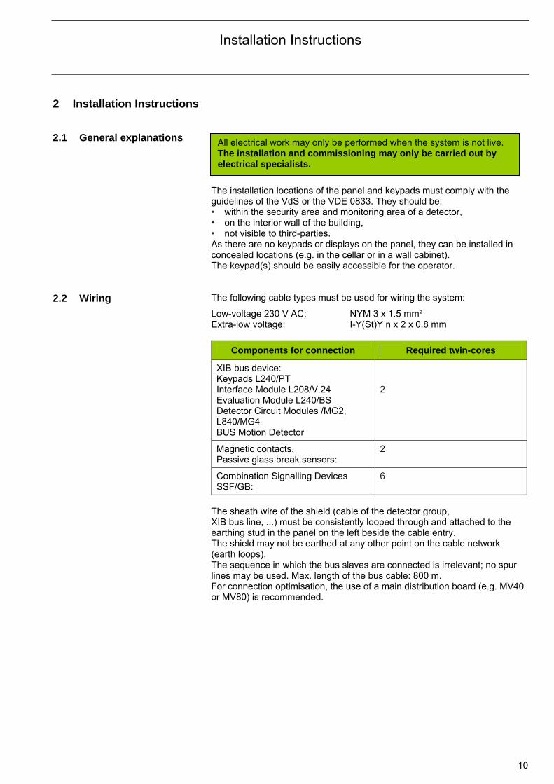
2.2 Wiring The following cable types must be used for wiring the system:
Low-voltage 230 V AC: NYM 3 x 1.5 mm² Extra-low voltage: I-Y(St)Y n x 2 x 0.8 mm
Components for connection Required twin-cores
XIB bus device: Keypads L240/PT Interface Module L208/V.24 Evaluation Module L240/BS Detector Circuit Modules /MG2, L840/MG4 BUS Motion Detector
2
Magnetic contacts, Passive glass break sensors:
2
Combination Signalling Devices SSF/GB:
6
The sheath wire of the shield (cable of the detector group, XIB bus line, ...) must be consistently looped through and attached to the earthing stud in the panel on the left beside the cable entry. The shield may not be earthed at any other point on the cable network (earth loops). The sequence in which the bus slaves are connected is irrelevant; no spur lines may be used. Max. length of the bus cable: 800 m. For connection optimisation, the use of a main distribution board (e.g. MV40 or MV80) is recommended.
All electrical work may only be performed when the system is not live. The installation and commissioning may only be carried out by electrical specialists.
Installation Instructions
11
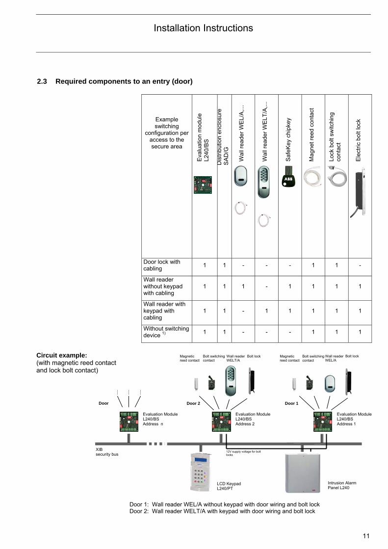
2.3 Required components to an entry (door)
Example switching
configuration per access to the secure area
Eva
luat
ion
mo
dule
L2
40/
BS
Dis
trib
utio
n e
ncl
osur
e
SA
D/G
Wal
l rea
der
WE
L/A
,...
Wal
l rea
der
WE
LT/A
,...
Saf
eKey
chi
pkey
Mag
net
ree
d co
ntac
t
Lock
bo
lt sw
itchi
ng
cont
act
Ele
ctric
bo
lt lo
ck
Door lock with cabling 1 1 - - - 1 1 -
Wall reader without keypad with cabling
1 1 1 - 1 1 1 1
Wall reader with keypad with cabling
1 1 - 1 1 1 1 1
Without switching device 1) 1 1 - - - 1 1 1
Door 1: Wall reader WEL/A without keypad with door wiring and bolt lock Door 2: Wall reader WELT/A with keypad with door wiring and bolt lock
Circuit example: (with magnetic reed contact and lock bolt contact)
Intrusion Alarm Panel L240
LCD Keypad L240/PT
Evaluation Module L240/BS Address n
Evaluation Module L240/BS Address 2
Evaluation ModuleL240/BS Address 1
Magnetic reed contact
Bolt switching contact
Wall readerWELT/A
Bolt lock Magnetic reed contact
Bolt switching contact
Wall readerWEL/A
Bolt lock
Door 1 Door 2Door
XIB security bus
12V supply voltage for bolt locks
Installation Instructions
12
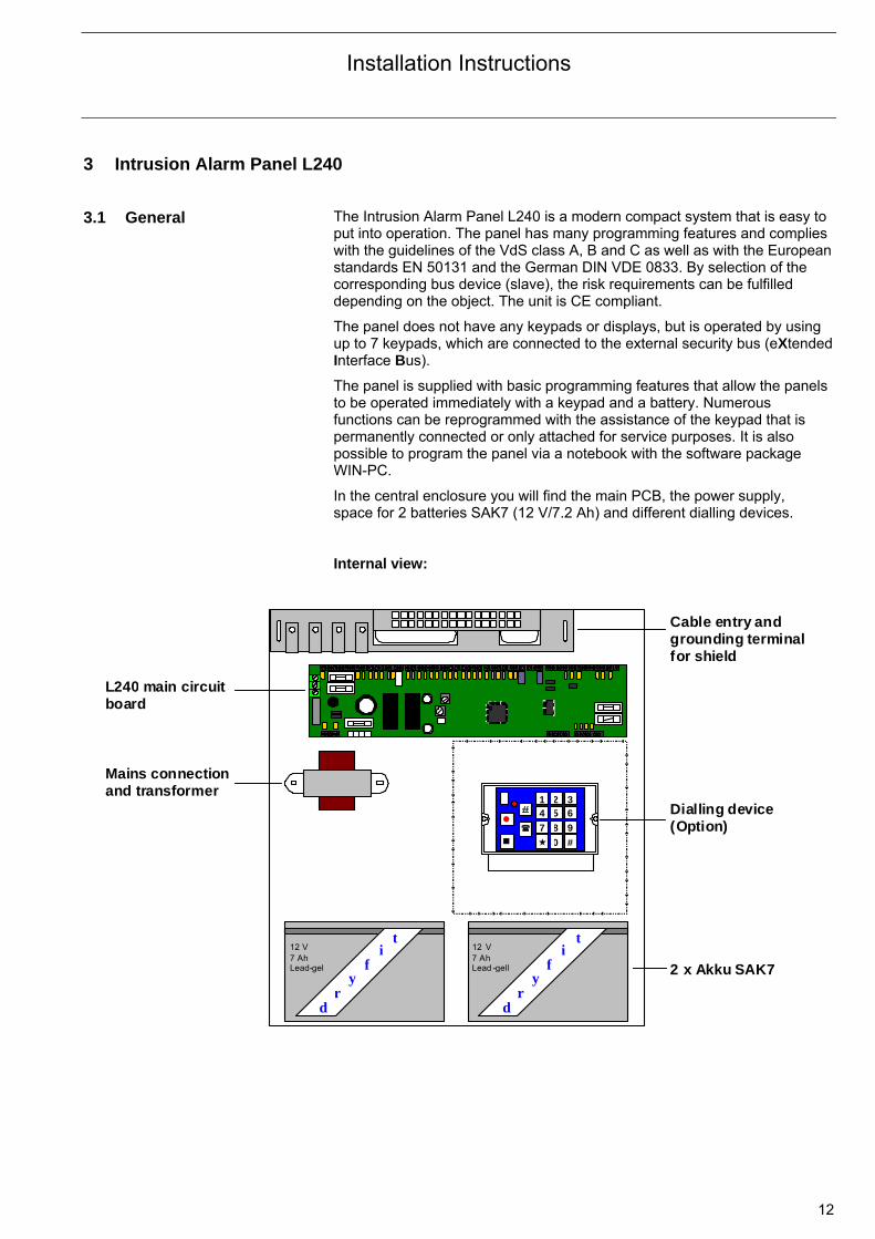
3 Intrusion Alarm Panel L240 3.1 General The Intrusion Alarm Panel L240 is a modern compact system that is easy to
put into operation. The panel has many programming features and complies with the guidelines of the VdS class A, B and C as well as with the European standards EN 50131 and the German DIN VDE 0833. By selection of the corresponding bus device (slave), the risk requirements can be fulfilled depending on the object. The unit is CE compliant.
The panel does not have any keypads or displays, but is operated by using up to 7 keypads, which are connected to the external security bus (eXtended Interface Bus).
The panel is supplied with basic programming features that allow the panels to be operated immediately with a keypad and a battery. Numerous functions can be reprogrammed with the assistance of the keypad that is permanently connected or only attached for service purposes. It is also possible to program the panel via a notebook with the software package WIN-PC.
In the central enclosure you will find the main PCB, the power supply, space for 2 batteries SAK7 (12 V/7.2 Ah) and different dialling devices. Internal view:
1 2 34 5 6
7 8 9
0 #
12 V 7 Ah Lead-gel
d r
y f
it
12 V7 AhLead -gell
d r
yf
i t
L240 main circuit board
Cable entry and grounding terminal for shield
Dialling device (Option)
2 x Akku SAK7
Mains connection and transformer
Installation Instructions
13
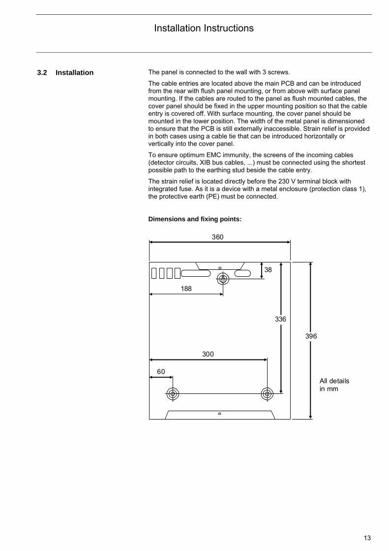
3.2 Installation The panel is connected to the wall with 3 screws.
The cable entries are located above the main PCB and can be introduced from the rear with flush panel mounting, or from above with surface panel mounting. If the cables are routed to the panel as flush mounted cables, the cover panel should be fixed in the upper mounting position so that the cable entry is covered off. With surface mounting, the cover panel should be mounted in the lower position. The width of the metal panel is dimensioned to ensure that the PCB is still externally inaccessible. Strain relief is provided in both cases using a cable tie that can be introduced horizontally or vertically into the cover panel.
To ensure optimum EMC immunity, the screens of the incoming cables (detector circuits, XIB bus cables, ...) must be connected using the shortest possible path to the earthing stud beside the cable entry.
The strain relief is located directly before the 230 V terminal block with integrated fuse. As it is a device with a metal enclosure (protection class 1), the protective earth (PE) must be connected. Dimensions and fixing points:
396
336
188
60
300
360
38
All details in mm
Installation Instructions
14
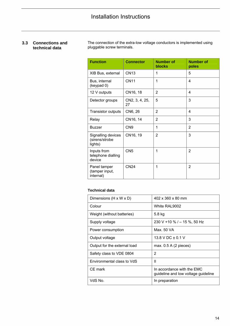
3.3 Connections and technical data
The connection of the extra-low voltage conductors is implemented using pluggable screw terminals.
Function Connector Number of blocks
Number of poles
XIB Bus, external CN13 1 5
Bus, internal (keypad 0)
CN11 1 4
12 V outputs CN16, 18 2 4
Detector groups CN2, 3, 4, 25, 27
5 3
Transistor outputs CN6, 26 2 4
Relay CN16, 14 2 3
Buzzer CN9 1 2
Signalling devices (sirens/strobe lights)
CN16, 19 2 3
Inputs from telephone dialling device
CN5 1 2
Panel tamper (tamper input, internal)
CN24 1 2
Technical data
Dimensions (H x W x D) 402 x 360 x 80 mm
Colour White RAL9002
Weight (without batteries) 5.8 kg
Supply voltage 230 V +10 % / – 15 %, 50 Hz
Power consumption Max. 50 VA
Output voltage 13.8 V DC ± 0.1 V
Output for the external load max. 0.5 A (2 pieces)
Safety class to VDE 0804 2
Environmental class to VdS II
CE mark In accordance with the EMC guideline and low voltage guideline
VdS No. In preparation
Installation Instructions
15
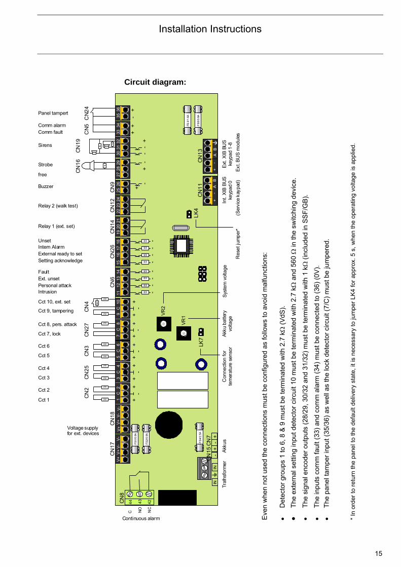
Circuit diagram:
36
35
32
31
30
18
1716
1534
33
29
28
27
26
2524
23
2221
20
1914
1312
11
10C
9
8 C
7
6 C
5
4 C
3
2 C
1
V-
V-
V+
V+
C
NO
NC
CN
8
44
43
42
- +
-
+
V-
V-
V+
V
+
IN
IN
B
A
- +
- +
B
A
FS
1/0.
8A
FS
2/0.
8A
FS
4/2.
5A
FS3/
1.6A
FS
5/0.
8A
+
- +
+
+-
--
+-
+
820 -
820 -
820 -
820 -
820 -
820 -
820 -
820 -
560
2k7
2k7
2k7
2k7
2k7
2k7
2k7
2k7
2k7
1k 1k
1k
CN
12
C
N9
CN
5
CN
24
CN
19
CN
16
CN
14
C
N2
6
CN
6
CN
4
CN
27
CN
3
CN
25
C
N2
CN
18
C
N1
7
CN
13
CN
11
LK
7
Int.
XIB
BU
S
keyp
ad 0
E
xt. X
IB B
US
ke
ypad
1-8
C
onne
ctio
n fo
r te
mer
atur
e se
nsor
A
kkus
Tr
afns
form
er
Continuous alarm
Voltage supply for ext. devices
Cct 2
Cct 9, tampering
Cct 10, ext. set
Cct 8, pers. attack
Cct 7, lock
Cct 6
Cct 5
Cct 4
Cct 3
Intrusion Personal attack Ext. unset Fault
Setting acknowledge External ready to set Intern Alarm Unset
Relay 1 (ext. set)
Relay 2 (walk test)
Buzzer
free
Panel tampert
Comm alarm Comm fault
LK
4
CN
7
CN
15
++
-+
+-
++
-+
+-
++
-
Strobe
Sirens
VR
1 VR
2
Akk
u ba
ttery
vo
ltage
S
yste
m v
olta
ge
Cct 1
Res
et ju
mpe
r*
(Ser
vice
kay
pad)
E
xt. B
US
mod
ules
Eve
n w
hen
not u
sed
the
conn
ectio
ns m
ust b
e co
nfig
ured
as
follo
ws
to a
void
mal
func
tions
:
Det
ecto
r gr
oups
1 to
6, 8
& 9
mus
t be
term
inat
ed w
ith 2
.7 k
(V
dS).
T
he e
xter
nal s
ettin
g in
put d
etec
tor
circ
uit 1
0 m
ust b
e te
rmin
ated
with
2.7
k
and
560
in
the
switc
hing
dev
ice.
T
he s
igna
l enc
oder
out
puts
(28
/29,
30/
32 a
nd 3
1/32
) m
ust b
e te
rmin
ated
with
1 k
Ω (
incl
uded
in S
SF
/GB
).
T
he in
puts
com
m fa
ult (
33)
and
com
m a
larm
(34
) m
ust b
e co
nnec
ted
to (
36)
(0V
).
T
he p
anel
tam
per
inpu
t (35
/36)
as
wel
l as
the
lock
det
ecto
r ci
rcui
t (7/
C)
mus
t be
jum
pere
d.
* In
ord
er to
ret
urn
the
pane
l to
the
defa
ult
del
iver
y st
ate,
it is
nec
essa
ry to
jum
per
LK4
for
appr
ox. 5
s, w
hen
the
oper
atin
g vo
ltag
e is
app
lied.
Installation Instructions
16
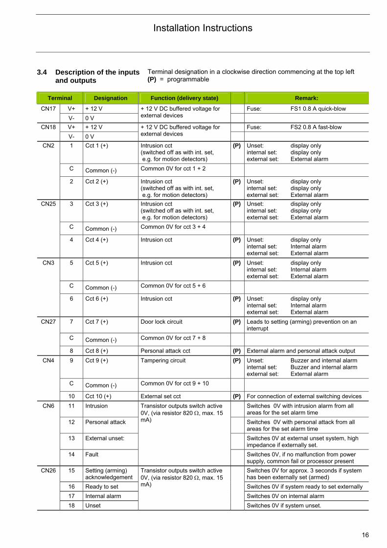
3.4 Description of the inputs and outputs
Terminal designation in a clockwise direction commencing at the top left (P) = programmable
Terminal Designation Function (delivery state) Remark: V+ + 12 V Fuse: FS1 0.8 A quick-blow CN17 V- 0 V
+ 12 V DC buffered voltage for external devices
V+ + 12 V Fuse: FS2 0.8 A fast-blow CN18 V- 0 V
+ 12 V DC buffered voltage for external devices
1 Cct 1 (+) Intrusion cct (switched off as with int. set, e.g. for motion detectors)
(P) Unset: display only internal set: display only external set: External alarm
C Common (-) Common 0V for cct 1 + 2
CN2
2 Cct 2 (+) Intrusion cct (switched off as with int. set, e.g. for motion detectors)
(P) Unset: display only internal set: display only external set: External alarm
3 Cct 3 (+) Intrusion cct (switched off as with int. set, e.g. for motion detectors)
(P) Unset: display only internal set: display only external set: External alarm
C Common (-) Common 0V for cct 3 + 4
CN25
4 Cct 4 (+) Intrusion cct (P) Unset: display only internal set: Internal alarm external set: External alarm
5 Cct 5 (+) Intrusion cct (P) Unset: display only internal set: Internal alarm external set: External alarm
C Common (-) Common 0V for cct 5 + 6
CN3
6 Cct 6 (+) Intrusion cct (P) Unset: display only internal set: Internal alarm external set: External alarm
7 Cct 7 (+) Door lock circuit (P) Leads to setting (arming) prevention on an interrupt
C Common (-) Common 0V for cct 7 + 8
CN27
8 Cct 8 (+) Personal attack cct (P) External alarm and personal attack output 9 Cct 9 (+) Tampering circuit
(P) Unset: Buzzer and internal alarm
internal set: Buzzer and internal alarm external set: External alarm
C Common (-) Common 0V for cct 9 + 10
CN4
10 Cct 10 (+) External set cct (P) For connection of external switching devices 11 Intrusion Switches 0V with intrusion alarm from all
areas for the set alarm time 12 Personal attack Switches 0V with personal attack from all
areas for the set alarm time 13 External unset: Switches 0V at external unset system, high
impedance if externally set.
CN6
14 Fault
Transistor outputs switch active 0V, (via resistor 820 , max. 15 mA)
Switches 0V, if no malfunction from power supply, common fail or processor present
15 Setting (arming) acknowledgement
Switches 0V for approx. 3 seconds if system has been externally set (armed)
16 Ready to set Switches 0V if system ready to set externally 17 Internal alarm Switches 0V on internal alarm
CN26
18 Unset
Transistor outputs switch active 0V, (via resistor 820 , max. 15 mA)
Switches 0V if system unset.

Installation Instructions
17
Terminal Designation Function (delivery state) Remark: 19 Relay 1 (NO) Relay switches with external set 20 Relay 1 (NC)
CN14
21 Relay 1 (common)
External set (P)
22 Relay 2 (NO) 23 Relay 2 (NC)
CN12
24 Relay 2 (common)
Walk test (P) Relay switches, if the walk test function on the keypad has been activated
25 Internal buzzer (+) CN9 26 Internal buzzer (-)
Switches with system interrupt, tamper alarm (unset) and after unset, in order to draw attention to a triggered alarm.
27 free
28 Strobe light (+)
CN16
29 Strobe light (-) (Active 0V) Switches with external alarm until reset. Fuse
FS3 800 mA quick-blow
30 Siren 1 (-) (Active 0V)
31 Siren 2 (-) (Active 0V)
CN19
32* Siren 1 & 2 (+)
Switches with external alarm for the set alarm time (180 seconds) Fuse FS3 800 mA quick-blow
33 Comm fail fault Connection of the fault relay of the comm fault. Normally connected with jumper to 0 V.
With an open contact on the comm (fault) of the setting prevention
CN5
34 Comm fault alarm (Negative acknowledgement)
Connection of the alarm relay of the comm fault. Only if the panel is programmed for a silent alarm. Normally connected with jumper to 0 V.
Generates a local alarm, if the comm fault could not issue a silent alarm.
35 Panel tamper (+) CN24 36 Common (-)
Panel tamper of the central enclosure
Unset: Buzzer and internal alarm internal set: Buzzer and internal alarm external set: External alarm
+,-,A,B External Bus (XIB) CN13
For connection of keypads (1-7) and bus modules
Fuse FS3 800 mA quick-blow (not keypad 0)
CN11 +,-,A,B Internal bus for keypad 0 (service keypad)
Connection of the engineer keypad (address 0)
VR 1 Battery charging voltage
Factory setting 13.8 V at 20°C.
VR 2 Systems voltage Factory setting 14.0 V.
LK7 Temperature sensor
For temperature dependent charging voltage of the battery
The temperature sensor is connected as near as possible to the batters with a cable tie.
CN7 +, - Battery 2
CN15 +, - Battery 1
AC IN, IN GND
approx. 20 V AC from transformer
From the transformer and mains connection with integrated fuse, 400 mA slow-blow.
CN8 42 Relay (NC) Permanent alarm relay
43 Relay (NO)
44 Relay 1 (common)
Switches with local alarm until reset.
- On VdS systems, siren 2 must be supplied by terminal V+ (CN17 or 18).
- The transistor outputs 1-8 are assigned in the delivery state with the functions of area 1 described in the table.
Note: Output 1 “Intrusion” switches with an intrusion alarm from all areas. Output 2 “Personal attack” switches with an intrusion alarm from all areas. It can be reprogrammed (output address 0).

Commissioning
18
4 Commissioning 4.1 Basic expansion This chapter describes how to put a panel in the basic panel configuration,
i.e. without expansion modules, into operation.
In the default delivery state, the panel recognizes a keypad as the only bus device that has been set with address 1 and connected to the external bus (terminal CN13).
For commissioning and addressing of the keypad L240/PT, see chapter 5. Programming of further bus devices is implemented using the keypad.
It is also possible to connect a keypad L240/PT with address 0 to the internal
bus (left connection slot, terminal CN11). This so-called “Engineer keypad” can be connected to the bus and disconnected at any time. It does not need to be logged off and is not monitored to ensure that it is present. It is
recommended that an “Engineer keypad” is connected in particular during commissioning. The states of the panels can be displayed as a result during commissioning (e.g. connection of a detector circuit).
4.2 Direct connection of the
inputs and outputs
In the first step, the panel is put into service without connected detectors, switching device and signalling devices. Before the panel is switched on, all inputs and the monitored outputs must have the accompanying terminating resistors inserted: • Detector circuits 1 to 6, 8 to 10 with 2.7 kOhm (colour code
commences with red-violet) • Jumper detector circuit 7 without a resistor (wire link) • Connect the inputs comm fault (33), comm alarm (34) and panel
tamper (35) with 0 V (36). • The monitored outputs for sirens and strobe lights should each be
terminated with 1 kOhm (colour code commences with brown-black) Connect an L240/PT keypad with address 1 on the right bus terminal (CN13), switch on the mains supply and connect the batteries (any sequence acceptable). On the keypad the software version of the keypad appears on the display (for about 2 seconds)
PX KP Type-2 Version 3.01
As soon as the keypad communicates with the panel, the green LED switches from a flashing to a permanently on state and the software version of the panel is displayed
ABB L240 V4.70A
The description of the buttons on the keypad can be found in chapter 5. Connect the temperature sensor for the battery and fix to the battery (e.g. with a cable tie). The Intrusion Alarm Panel is now ready for operation, ready to set and there are no faults present. On the “Ready to Set” (terminal 16), transistor output a voltage of 13.0 V to
“V+” can be measured. A wide range of functions can be tested (e.g. internal set) and/or programming with a keypad can be undertaken.

Commissioning
19
If the LED continues to flash, check if • address 1 is set on the keypad
• the XIB security bus has been correctly connected. 4.3 External connection of
the inputs and outputs After the panel is ready for operation, the termination resistors or wire jumpers (links) are removed and the external cables to the detectors, setting (arming) device and signalling devices are connected. Connection of the detector circuits: • Remove the termination resistor of detector circuit 1 on the terminal block
of the panel. Detector circuit 1 interrupt is displayed after pressing button 5 (display faulty detector) on the keypad.
• Connect the cable to the detectors (e.g. motion detectors) of circuit 1. Here, a termination resistor must be connected once at the end of the cable. Otherwise, the cable is not monitored. Only one termination resistor is allowed for each detector group.
• If circuit 1 is OK/closed (motion detector does not detect a motion), a circuit interruption is no longer displayed on the keypad (button 5).
• Check by inducing a fault on circuit 1 (motion detector detects a motion) if a fault is detected by the panel and if it is displayed on the keypad.
• Successively put the other detector groups 2 to 9 into operation in the same manner as described for circuit 1. However, circuit 7 (lock detector circuit) does not require a termination resistor. An interrupt on circuit 8 (personal attack) and 9 (tampering) must be reset using the Reset function on the keypad.
• Connect the setting (arming) device (e.g. contact lock) to circuit 10. With the connection of a setting device on the XIB bus (SafeKey Evaluation Module L240/BS), circuit 10 should be re-programmed to another circuit type and terminated with the corresponding resistor.
Connection of the signalling device: • Remove the terminating resistor for the strobe lights on the terminal block
of the panel (tampering alarm is triggered!). • Connect the cable to the ABB strobe light. The terminating resistor is
already integrated into the strobe lights and connection of an additional resistor is not necessary.
• The triggered tamper alarm is reset with the Reset on the keypad. • Check the strobe light in the test menu (see chapter 7.1.3 ). • Commission both ABB sirens as described with the strobe light.
It is recommended that you only connect both sirens when the Intrusion Alarm System (incl. bus modules) is ready to operate. Telephone dialling device: • Remove the wire links of the comm fault and comm alarm (fault signal is
triggered!). • Connect the comm fault and comm alarm feedbacks from the telephone
dialling devices. Panel tamper connection: • Remove the wire jumper for the panel tamper (tamper alarm is
triggered!). • Connect the connection cable for the panel tamper of the panel. • The triggered tamper alarm is reset with the Reset on the keypad
(enclosure must be closed).

Commissioning
20
Note: • If a telephone-dialling device is not connected, the inputs comm fault and
comm alarm must be connected by jumper to 0 V. • If detector circuits are not assigned, a terminating resistor must be
inserted. • In the default delivery state the reset of a tamper alarm is enabled.
4.4 Expansion of the panel
with bus nodes The basic panel configuration can be expanded by many bus modules. The connection or removal of bus modules may only be performed when the system power is switched off! Commissioning of the bus devices: • The panel should be ready for operation and no faults should be present.• Disconnect the mains and battery supply. • Assign addresses to the individual bus modules to comply with their
address range and address tables. • Connect all bus modules to the XIB security bus. • Connect the corresponding components to the bus modules (e.g. motion
sensor or switching device). • Connect the mains and battery supply. • Enable the individual bus modules in the Edit menu and change the
parameters if necessary (e.g. area or detector circuit type). • Teach-in the bus detector circuit modules. • If bus modules are not logged on or are logged off again, they must be
disconnected from the XIB security bus. Further information should be taken from the respective chapters (device descriptions or programming menu). Addressing of the bus device All bus devices must be addressed (“numbered successively”) manually via DIP switch or jumpers. The bus modules for the motion detectors are addressed automatically by the panel. The individual module types have their own addressing range. The addressing range for each module type
commences with “1” and must be successive (1, 2, 3, … 4). The address table should be taken from the respective chapter of the device descriptions.
Module type Bus module Addressing range Keypad L240/PT 1 to 7 Detector circuit module L840/MG4, L240/MG2 1 to 24 Motion detector M. L240/IR-XB 1 to 40 SafeKey module L240/BS 1 to 8 Interface module L208/V.24 2 LAN interface L240/IP 2
With the number of circuits and bus modules, it is important to observe that the total number of circuits does not exceed 80. These include the: • 10 circuits for the main PCB. • Circuit modules L840/MG 4 each with four circuits. • Detector circuit modules L240/MG 2 each with two circuits. • Bus motion detector modules with one detector each.

Commissioning
21
Jumper link contact of the panel tamper during commissioning All modules feature panel tamper contacts and signal a tamper alarm if they are not actuated. For this reason, we recommend that you apply a short circuit to the panel tamper during commissioning with the provided DIP switch or jumper. After work has been completed, the panel tamper must be reactivated! The tables for addressing as well as positioning of the DIP switch can be found in the respective chapters of the device descriptions.
Operation of the L240
22
5 Keypad L240/PT
5.1 General description
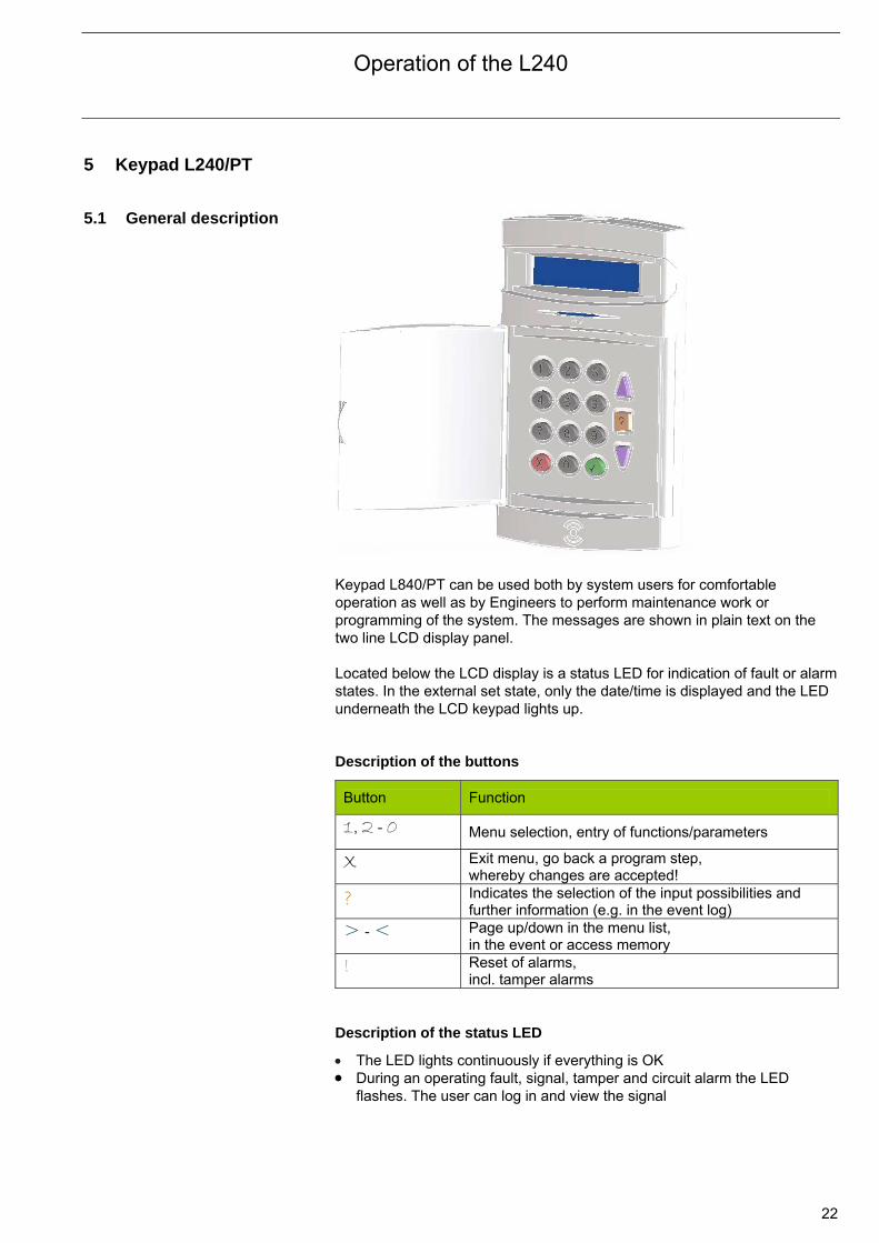
Keypad L840/PT can be used both by system users for comfortable operation as well as by Engineers to perform maintenance work or programming of the system. The messages are shown in plain text on the two line LCD display panel. Located below the LCD display is a status LED for indication of fault or alarm states. In the external set state, only the date/time is displayed and the LED underneath the LCD keypad lights up. Description of the buttons
Button Function
1, 2 - 0 Menu selection, entry of functions/parameters
X Exit menu, go back a program step, whereby changes are accepted!
? Indicates the selection of the input possibilities and further information (e.g. in the event log)
> - < Page up/down in the menu list, in the event or access memory
! Reset of alarms, incl. tamper alarms
Description of the status LED
The LED lights continuously if everything is OK During an operating fault, signal, tamper and circuit alarm the LED
flashes. The user can log in and view the signal

Operation of the L240
23
5.2 Connection The Intrusion Alarm Panel can be operated with up to 7 keypads L208/PT.
The keypads are connected to the external bus of the panel CN13 (+ – A B) with a 4-core cable. Each keypad must be assigned with its own address in the range from 1 to 7 when it is initially commissioned. During switch on, the following display for address assignment is displayed:
Address = 01 4 or X
The address must be entered as a 2-digit address (address 1 = 01). Acknowledge the address with button !. The first keypad is assigned with number 01, further keypads must be addressed successively (02, 03, … 07). The keypad with address 1 is automatically detected by the panel, further keypads must be enabled in the Engineer menu (see chapter 8.1.1 Menu 01 “Hardware”. Note: Should it be necessary to re-enter the address, the keypad must be opened when powered up (tamper alarm is activated!). Now press button ? and keep pressed for about 5 s until address entry mode appears.
The plug-in jumper LK1 is used for bypassing the panel tamper during commissioning. LK1 must be removed again after commissioning.
LCD
ABB L240/PT
7 6 5 4 3 2 1
Links for panel tamper contact
Panel tamper with spring
LK1
Buzzer
+ - A B
External bus (XIB)

Operation of the L240
24
6 Operation with Keypad L240/PT 6.1 General information The display and the buttons are illuminated as soon as a button is operated.
The lighting switches back off as soon as button X is pressed. The operation/programming is divided into different levels:
1. Operation by the operator without previous entry of the PIN code (access level 0)
2. Operation by the operator with previous entry of the PIN code (access level 1)
3. Operation by the Engineer with additional entry of the Engineer PIN code (access level 2)
4. Programming by the Engineer with additional entry of the Engineer PIN code
5. Management of the chip key/keypad code with additional management PIN code entry
In principle, each button is assigned with a function on every level. On each level, in which you are operating, there are buttons directly accessible, i.e. it is unnecessary to use the arrow keys to work through the menus, but you can do so in order to view the individual functions. In every level you can access all possible alternatives and further information with the assistance of the “Help” ? key. A menu can be exited with button X and you access a higher level; entries/changes performed are then automatically accepted. If an entry is not made within 30 s, the menu will be automatically exited. For the operator/user a maximum of 14 menu items are available that can be selected by entering a 2-digit entry. A part of the menu is only available after entry of a PIN code or only appears when the corresponding bus modules are connected. When a menu selection has been made, the options yes/no or on/off can be selected with the buttons 0 for off and no, and 1 for on and yes. After an option of this type has been set, it is active, i.e. it is unnecessary to press the ! button (with the exception of the setting of date and time). A menu can be exited with the button X. Generally, the keypad exits an access level if a button has not been pushed for about 30 seconds. After an alarm, this display is shown as soon as you log in with the 4-digit PIN code. Using the arrow buttons ><, you can page through several pages; the first alarm, which has occurred, is identified with “1”. You can exit these messages with X and are shown the display: “4= Reset”. The reset is carried out with the ! button. The alarm is deleted. A battery or mains fault display can be delayed by up to 15 minutes. The LED flashes and the transistor output “Fault” assumes a high resistance state (switches with no fault). An external alarm is not triggered. With a mains fault the panel can not be set externally, internal setting is however possible. The fault is deleted automatically when the mains voltage recovers. A battery fault points to a defective battery and leads to setting prevention (external and internal). It can only be deleted by a tamper reset.
Operation of the L240
25
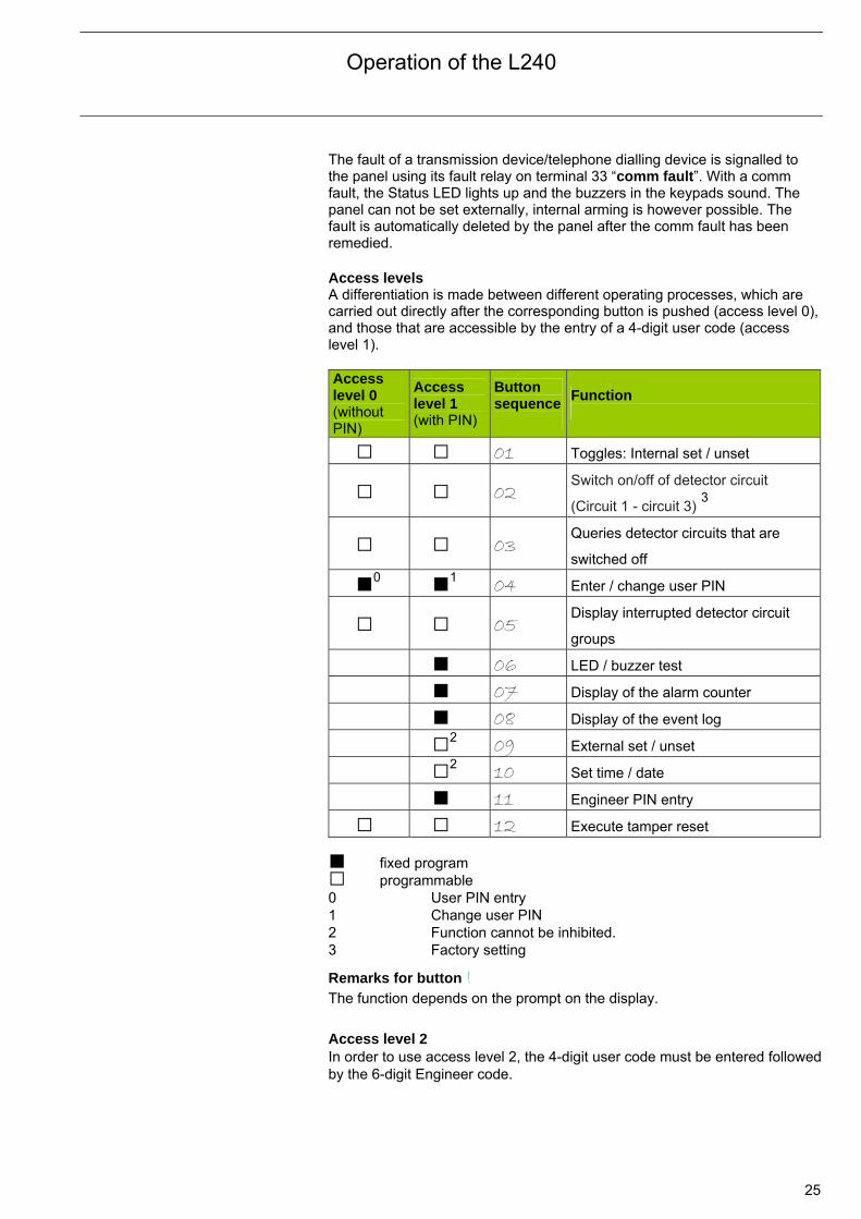
The fault of a transmission device/telephone dialling device is signalled to the panel using its fault relay on terminal 33 “comm fault”. With a comm fault, the Status LED lights up and the buzzers in the keypads sound. The panel can not be set externally, internal arming is however possible. The fault is automatically deleted by the panel after the comm fault has been remedied. Access levels A differentiation is made between different operating processes, which are carried out directly after the corresponding button is pushed (access level 0),and those that are accessible by the entry of a 4-digit user code (access level 1). Access level 0 (without PIN)
Access level 1 (with PIN)
Button sequence
Function
01 Toggles: Internal set / unset
02 Switch on/off of detector circuit
(Circuit 1 - circuit 3) 3
03 Queries detector circuits that are
switched off
0 1 04 Enter / change user PIN
05 Display interrupted detector circuit
groups
06 LED / buzzer test
07 Display of the alarm counter
08 Display of the event log
2 09 External set / unset
2 10 Set time / date
11 Engineer PIN entry
12 Execute tamper reset fixed program programmable 0 User PIN entry 1 Change user PIN
2 Function cannot be inhibited.
3 Factory setting
Remarks for button ! The function depends on the prompt on the display.
Access level 2 In order to use access level 2, the 4-digit user code must be entered followedby the 6-digit Engineer code.
Operation of the L240
26
6.2 Operation without PIN
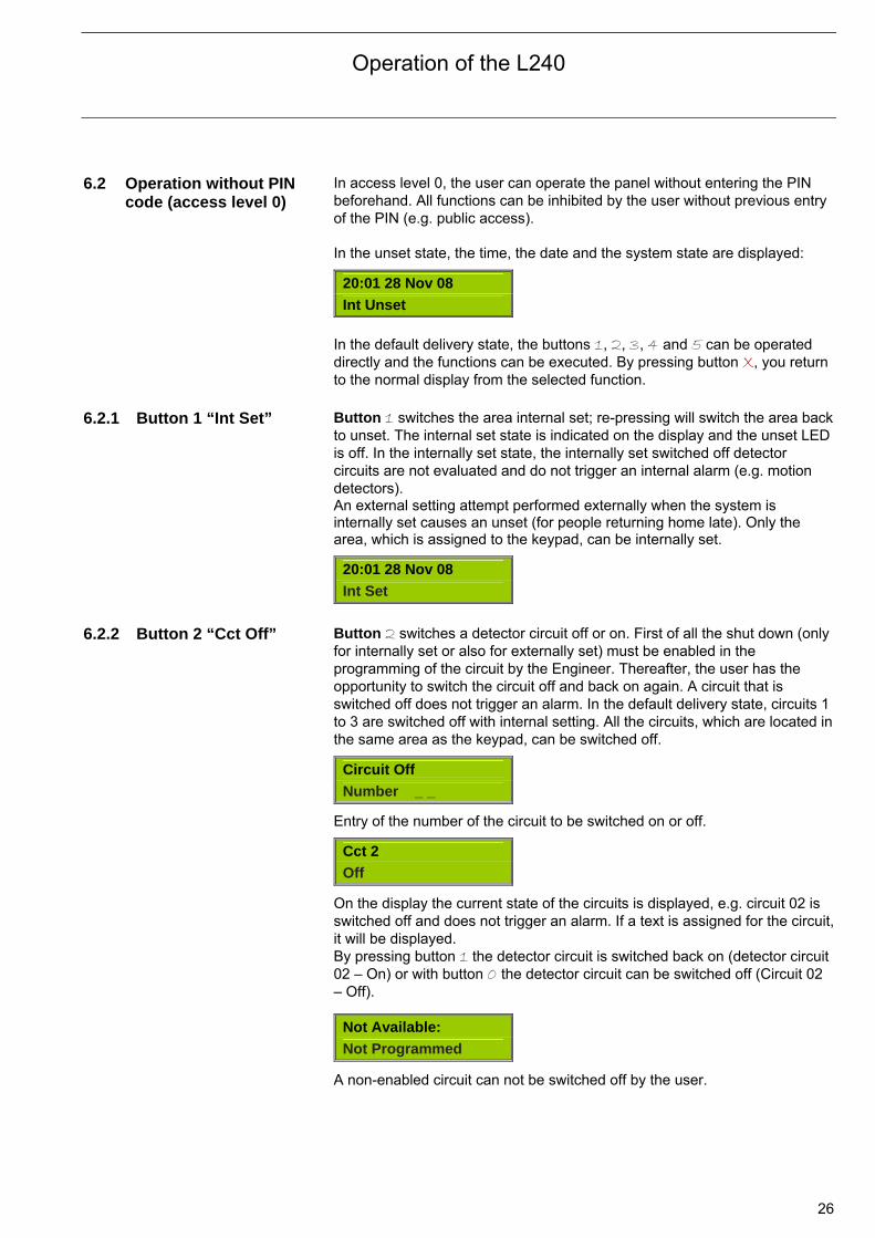
code (access level 0) In access level 0, the user can operate the panel without entering the PIN beforehand. All functions can be inhibited by the user without previous entry of the PIN (e.g. public access). In the unset state, the time, the date and the system state are displayed:
20:01 28 Nov 08 Int Unset
In the default delivery state, the buttons 1, 2, 3, 4 and 5 can be operated directly and the functions can be executed. By pressing button X, you return to the normal display from the selected function.
6.2.1 Button 1 “Int Set” Button 1 switches the area internal set; re-pressing will switch the area back
to unset. The internal set state is indicated on the display and the unset LED is off. In the internally set state, the internally set switched off detector circuits are not evaluated and do not trigger an internal alarm (e.g. motion detectors). An external setting attempt performed externally when the system is internally set causes an unset (for people returning home late). Only the area, which is assigned to the keypad, can be internally set.
20:01 28 Nov 08
Int Set 6.2.2 Button 2 “Cct Off” Button 2 switches a detector circuit off or on. First of all the shut down (only
for internally set or also for externally set) must be enabled in the programming of the circuit by the Engineer. Thereafter, the user has the opportunity to switch the circuit off and back on again. A circuit that is switched off does not trigger an alarm. In the default delivery state, circuits 1 to 3 are switched off with internal setting. All the circuits, which are located in the same area as the keypad, can be switched off.
Circuit Off
Number _ _
Entry of the number of the circuit to be switched on or off.
Cct 2
Off
On the display the current state of the circuits is displayed, e.g. circuit 02 is switched off and does not trigger an alarm. If a text is assigned for the circuit,it will be displayed. By pressing button 1 the detector circuit is switched back on (detector circuit 02 – On) or with button 0 the detector circuit can be switched off (Circuit 02 – Off).
A non-enabled circuit can not be switched off by the user.
Not Available:
Not Programmed
Operation of the L240
27
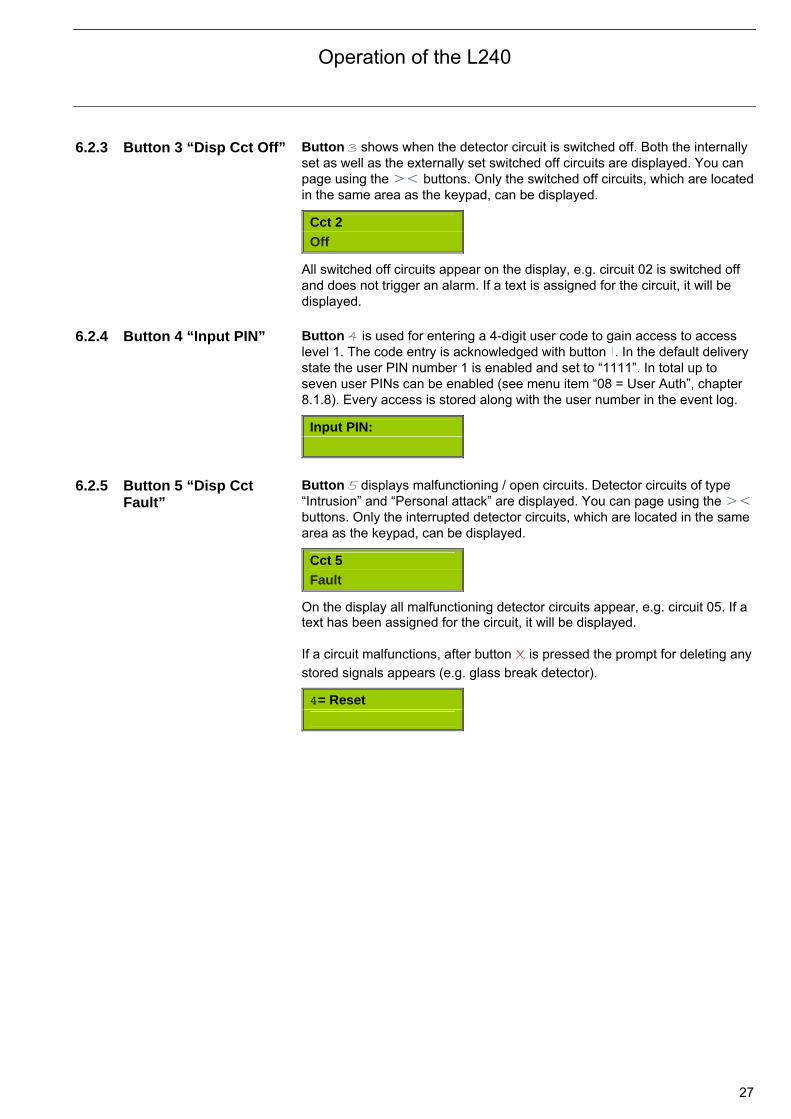
6.2.3 Button 3 “Disp Cct Off” Button 3 shows when the detector circuit is switched off. Both the internally set as well as the externally set switched off circuits are displayed. You can page using the >< buttons. Only the switched off circuits, which are located in the same area as the keypad, can be displayed.
Cct 2
Off
All switched off circuits appear on the display, e.g. circuit 02 is switched off and does not trigger an alarm. If a text is assigned for the circuit, it will be displayed.
6.2.4 Button 4 “Input PIN” Button 4 is used for entering a 4-digit user code to gain access to access
level 1. The code entry is acknowledged with button !. In the default delivery state the user PIN number 1 is enabled and set to “1111”. In total up to seven user PINs can be enabled (see menu item “08 = User Auth”, chapter 8.1.8). Every access is stored along with the user number in the event log.
Input PIN:
6.2.5 Button 5 “Disp Cct
Fault” Button 5 displays malfunctioning / open circuits. Detector circuits of type “Intrusion” and “Personal attack” are displayed. You can page using the >< buttons. Only the interrupted detector circuits, which are located in the same area as the keypad, can be displayed.
Cct 5
Fault
On the display all malfunctioning detector circuits appear, e.g. circuit 05. If a text has been assigned for the circuit, it will be displayed. If a circuit malfunctions, after button X is pressed the prompt for deleting any
stored signals appears (e.g. glass break detector).
4= Reset
Operation of the L240
28
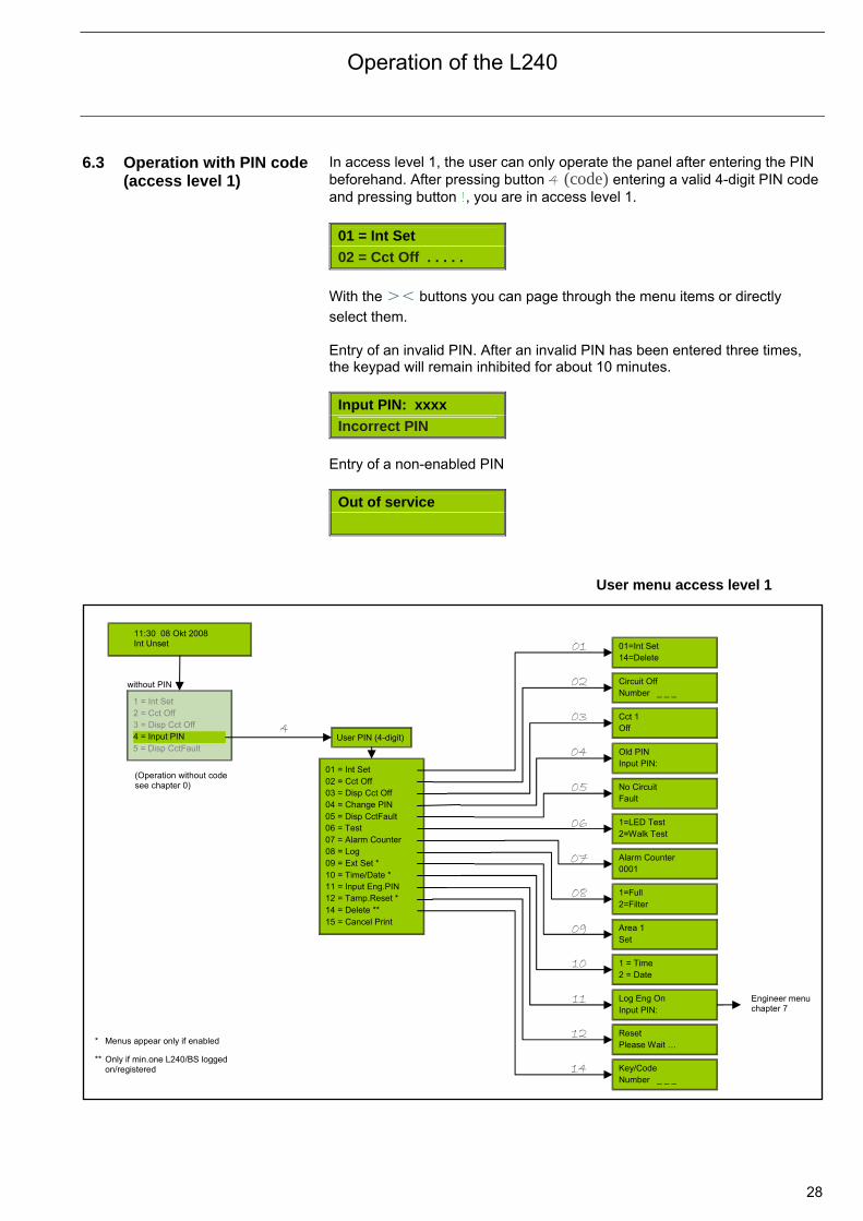
6.3 Operation with PIN code (access level 1)
In access level 1, the user can only operate the panel after entering the PIN beforehand. After pressing button 4 (code) entering a valid 4-digit PIN code and pressing button !, you are in access level 1.
01 = Int Set
02 = Cct Off . . . . .
With the >< buttons you can page through the menu items or directly
select them. Entry of an invalid PIN. After an invalid PIN has been entered three times, the keypad will remain inhibited for about 10 minutes.
Input PIN: xxxx
Incorrect PIN
Entry of a non-enabled PIN
Out of service
User menu access level 1
11:30 08 Okt 2008 Int Unset
without PIN
User PIN (4-digit)
01 = Int Set 02 = Cct Off03 = Disp Cct Off04 = Change PIN05 = Disp CctFault06 = Test07 = Alarm Counter08 = Log09 = Ext Set *10 = Time/Date *11 = Input Eng.PIN12 = Tamp.Reset *14 = Delete **
01=Int Set 14=Delete
1 = Int Set 2 = Cct Off 3 = Disp Cct Off 4 = Input PIN 5 = Disp CctFault
Circuit Off Number _ _ _
Cct 1 Off
Old PIN Input PIN:
No Circuit Fault
1=LED Test 2=Walk Test
Alarm Counter 0001
1=Full 2=Filter
Area 1 Set
1 = Time 2 = Date
Log Eng On Input PIN:
Reset Please Wait …
Key/Code Number _ _ _
* Menus appear only if enabled ** Only if min.one L240/BS logged
on/registered
01
02
03
04
05
06
07
08
09
10
11
12
14
4
15 = Cancel Print
Engineer menuchapter 7
(Operation without code see chapter 0)
Operation of the L240
29
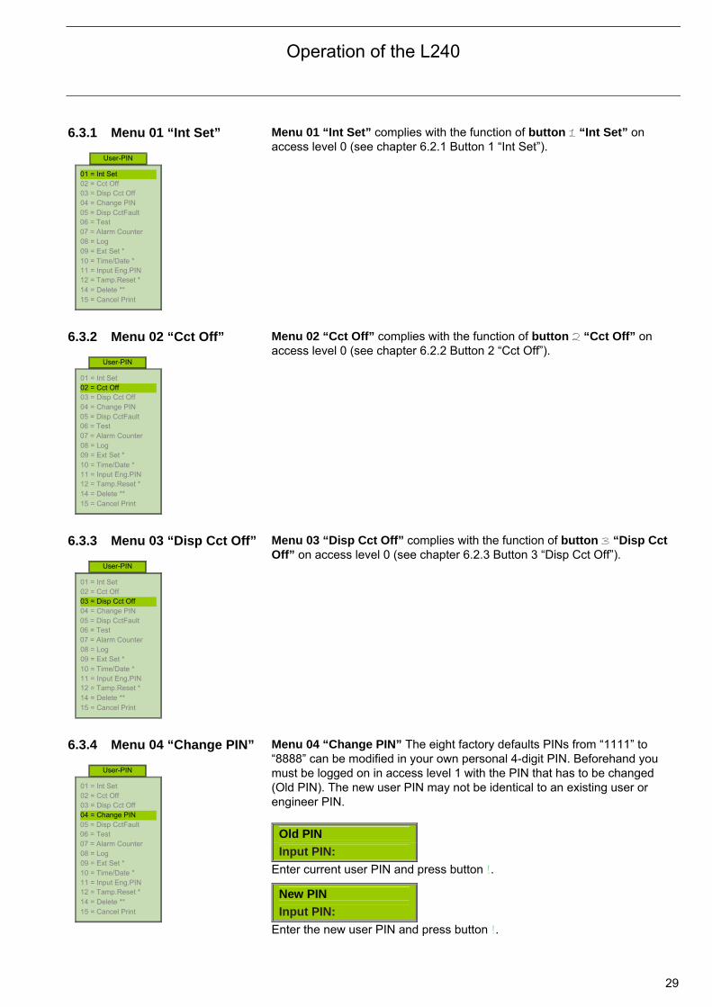
6.3.1 Menu 01 “Int Set”
Menu 01 “Int Set” complies with the function of button 1 “Int Set” on access level 0 (see chapter 6.2.1 Button 1 “Int Set”).
6.3.2 Menu 02 “Cct Off”
Menu 02 “Cct Off” complies with the function of button 2 “Cct Off” on access level 0 (see chapter 6.2.2 Button 2 “Cct Off”).
6.3.3 Menu 03 “Disp Cct Off”
Menu 03 “Disp Cct Off” complies with the function of button 3 “Disp Cct Off” on access level 0 (see chapter 6.2.3 Button 3 “Disp Cct Off”).
6.3.4 Menu 04 “Change PIN”
Menu 04 “Change PIN” The eight factory defaults PINs from “1111” to “8888” can be modified in your own personal 4-digit PIN. Beforehand you must be logged on in access level 1 with the PIN that has to be changed (Old PIN). The new user PIN may not be identical to an existing user or engineer PIN.
Old PIN
Input PIN:
Enter current user PIN and press button !.
New PIN
Input PIN:
Enter the new user PIN and press button !.
01 = Int Set 02 = Cct Off 03 = Disp Cct Off 04 = Change PIN 05 = Disp CctFault 06 = Test 07 = Alarm Counter 08 = Log 09 = Ext Set * 10 = Time/Date * 11 = Input Eng.PIN 12 = Tamp.Reset * 14 = Delete ** 15 = Cancel Print
User-PIN
01 = Int Set 02 = Cct Off 03 = Disp Cct Off 04 = Change PIN 05 = Disp CctFault 06 = Test 07 = Alarm Counter 08 = Log 09 = Ext Set * 10 = Time/Date * 11 = Input Eng.PIN 12 = Tamp.Reset * 14 = Delete ** 15 = Cancel Print
User-PIN
01 = Int Set 02 = Cct Off 03 = Disp Cct Off 04 = Change PIN 05 = Disp CctFault 06 = Test 07 = Alarm Counter 08 = Log 09 = Ext Set * 10 = Time/Date * 11 = Input Eng.PIN 12 = Tamp.Reset * 14 = Delete ** 15 = Cancel Print
User-PIN
01 = Int Set 02 = Cct Off 03 = Disp Cct Off 04 = Change PIN 05 = Disp CctFault 06 = Test 07 = Alarm Counter 08 = Log 09 = Ext Set * 10 = Time/Date * 11 = Input Eng.PIN 12 = Tamp.Reset * 14 = Delete ** 15 = Cancel Print
User-PIN
Operation of the L240
30
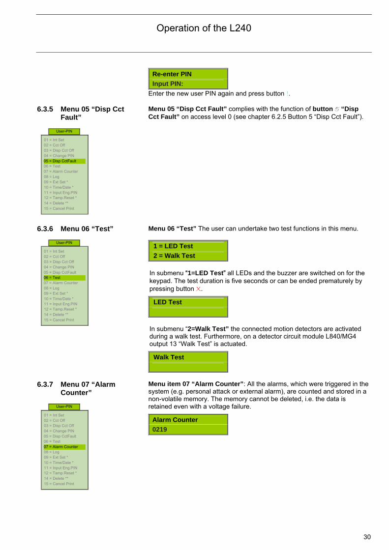
Re-enter PIN
Input PIN:
Enter the new user PIN again and press button !. 6.3.5 Menu 05 “Disp Cct
Fault”
Menu 05 “Disp Cct Fault” complies with the function of button 5 “Disp Cct Fault” on access level 0 (see chapter 6.2.5 Button 5 “Disp Cct Fault”).
6.3.6 Menu 06 “Test”
Menu 06 “Test” The user can undertake two test functions in this menu.
1 = LED Test
2 = Walk Test
In submenu “1=LED Test” all LEDs and the buzzer are switched on for the keypad. The test duration is five seconds or can be ended prematurely by pressing button X.
LED Test
In submenu “2=Walk Test” the connected motion detectors are activated during a walk test. Furthermore, on a detector circuit module L840/MG4 output 13 “Walk Test” is actuated.
Walk Test
6.3.7 Menu 07 “Alarm
Counter”
Menu item 07 “Alarm Counter”: All the alarms, which were triggered in the system (e.g. personal attack or external alarm), are counted and stored in a non-volatile memory. The memory cannot be deleted, i.e. the data is retained even with a voltage failure.
Alarm Counter 0219
01 = Int Set 02 = Cct Off 03 = Disp Cct Off 04 = Change PIN 05 = Disp CctFault 06 = Test 07 = Alarm Counter 08 = Log 09 = Ext Set * 10 = Time/Date * 11 = Input Eng.PIN 12 = Tamp.Reset * 14 = Delete ** 15 = Cancel Print
User-PIN
01 = Int Set 02 = Cct Off 03 = Disp Cct Off 04 = Change PIN 05 = Disp CctFault 06 = Test 07 = Alarm Counter 08 = Log 09 = Ext Set * 10 = Time/Date * 11 = Input Eng.PIN 12 = Tamp.Reset * 14 = Delete ** 15 = Cancel Print
User-PIN
01 = Int Set 02 = Cct Off 03 = Disp Cct Off 04 = Change PIN 05 = Disp CctFault 06 = Test 07 = Alarm Counter 08 = Log 09 = Ext Set * 10 = Time/Date * 11 = Input Eng.PIN 12 = Tamp.Reset * 14 = Delete ** 15 = Cancel Print
User-PIN
Operation of the L240
31
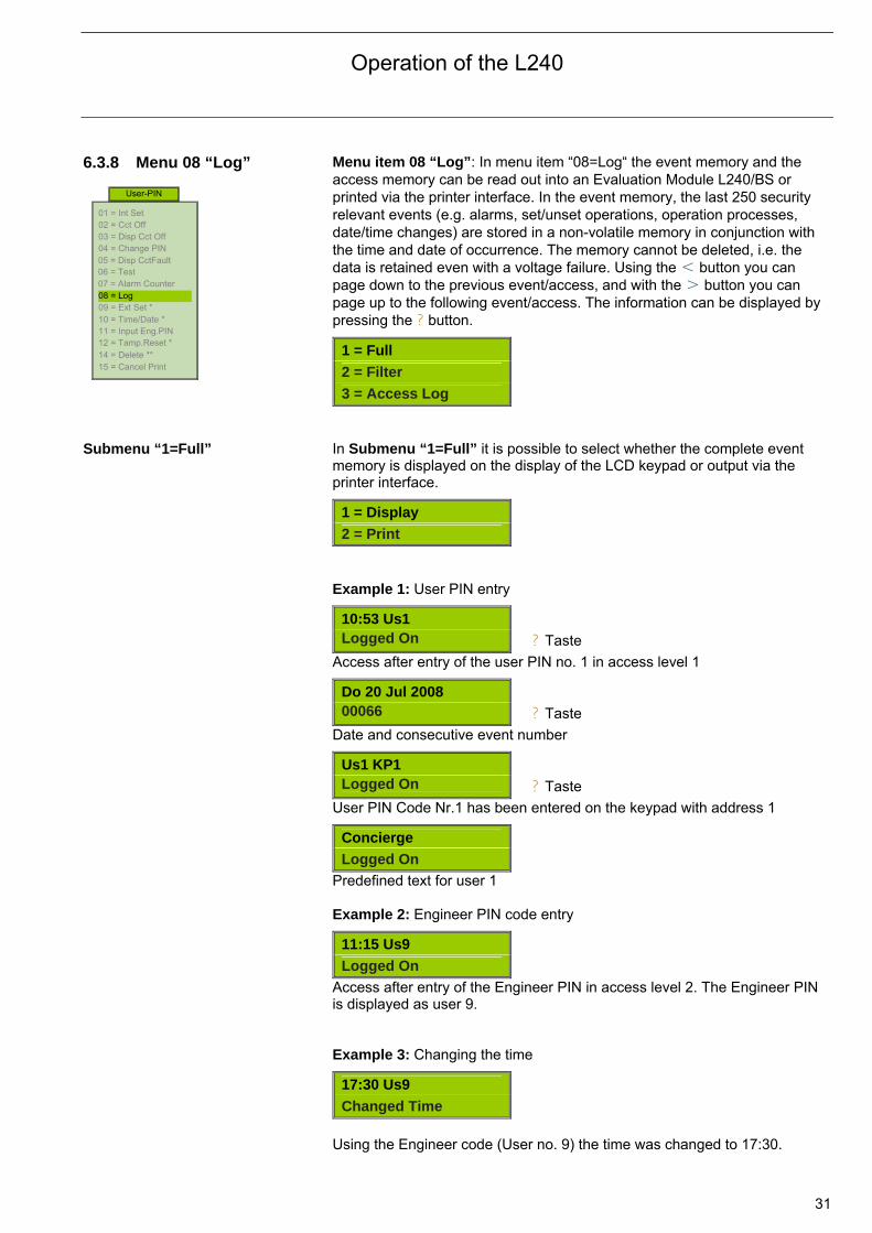
6.3.8 Menu 08 “Log”
Menu item 08 “Log”: In menu item “08=Log“ the event memory and the access memory can be read out into an Evaluation Module L240/BS or printed via the printer interface. In the event memory, the last 250 security relevant events (e.g. alarms, set/unset operations, operation processes, date/time changes) are stored in a non-volatile memory in conjunction with the time and date of occurrence. The memory cannot be deleted, i.e. the data is retained even with a voltage failure. Using the < button you can page down to the previous event/access, and with the > button you can page up to the following event/access. The information can be displayed by pressing the ? button.
1 = Full
2 = Filter
3 = Access Log Submenu “1=Full” In Submenu “1=Full” it is possible to select whether the complete event
memory is displayed on the display of the LCD keypad or output via the printer interface.
1 = Display
2 = Print
Example 1: User PIN entry
10:53 Us1 Logged On
Access after entry of the user PIN no. 1 in access level 1
Do 20 Jul 2008 00066
Date and consecutive event number
Us1 KP1 Logged On
User PIN Code Nr.1 has been entered on the keypad with address 1
Concierge
Logged On
Predefined text for user 1 Example 2: Engineer PIN code entry
11:15 Us9
Logged On
Access after entry of the Engineer PIN in access level 2. The Engineer PIN is displayed as user 9. Example 3: Changing the time
17:30 Us9
Changed Time
Using the Engineer code (User no. 9) the time was changed to 17:30.
01 = Int Set 02 = Cct Off 03 = Disp Cct Off 04 = Change PIN 05 = Disp CctFault 06 = Test 07 = Alarm Counter 08 = Log 09 = Ext Set * 10 = Time/Date * 11 = Input Eng.PIN 12 = Tamp.Reset * 14 = Delete ** 15 = Cancel Print
User-PIN
? Taste
? Taste
? Taste
Operation of the L240
32
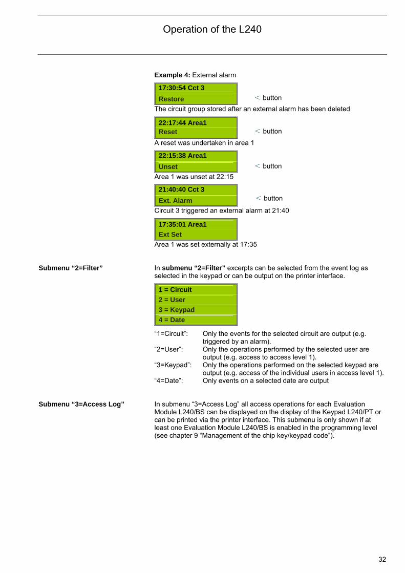
Example 4: External alarm
17:30:54 Cct 3
Restore
The circuit group stored after an external alarm has been deleted
22:17:44 Area1 Reset
A reset was undertaken in area 1
22:15:38 Area1
Unset
Area 1 was unset at 22:15
21:40:40 Cct 3
Ext. Alarm
Circuit 3 triggered an external alarm at 21:40
17:35:01 Area1
Ext Set
Area 1 was set externally at 17:35 Submenu “2=Filter” In submenu “2=Filter” excerpts can be selected from the event log as
selected in the keypad or can be output on the printer interface.
1 = Circuit
2 = User
3 = Keypad
4 = Date
“1=Circuit”: Only the events for the selected circuit are output (e.g. triggered by an alarm).
“2=User”: Only the operations performed by the selected user are output (e.g. access to access level 1).
“3=Keypad”: Only the operations performed on the selected keypad are output (e.g. access of the individual users in access level 1).
“4=Date”: Only events on a selected date are output Submenu “3=Access Log” In submenu “3=Access Log” all access operations for each Evaluation
Module L240/BS can be displayed on the display of the Keypad L240/PT or can be printed via the printer interface. This submenu is only shown if at least one Evaluation Module L240/BS is enabled in the programming level (see chapter 9 “Management of the chip key/keypad code”).
< button
< button
< button
< button
Operation of the L240
33
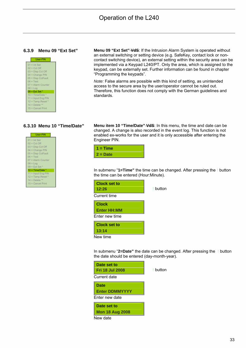
6.3.9 Menu 09 “Ext Set”
Menu 09 “Ext Set” VdS: If the Intrusion Alarm System is operated without an external switching or setting device (e.g. SafeKey, contact lock or non-contact switching device), an external setting within the security area can be implemented via a Keypad L240/PT. Only the area, which is assigned to the keypad, can be externally set. Further information can be found in chapter “Programming the keypads”.
Note: False alarms are possible with this kind of setting, as unintended access to the secure area by the user/operator cannot be ruled out. Therefore, this function does not comply with the German guidelines and standards.
6.3.10 Menu 10 “Time/Date”
Menu item 10 “Time/Date” VdS: In this menu, the time and date can be changed. A change is also recorded in the event log. This function is not enabled ex-works for the user and it is only accessible after entering the Engineer PIN.
1 = Time 2 = Date
In submenu “1=Time” the time can be changed. After pressing the ! button the time can be entered (Hour:Minute).
Clock set to 12:26
Current time
Clock
Enter HH:MM
Enter new time
Clock set to
13:14
New time In submenu “2=Date” the date can be changed. After pressing the ! button the date should be entered (day-month-year).
Date set to Fri 18 Jul 2008
Current date
Date
Enter DDMMYYYY
Enter new date
Date set to
Mon 18 Aug 2008
New date
01 = Int Set 02 = Cct Off 03 = Disp Cct Off 04 = Change PIN 05 = Disp CctFault 06 = Test 07 = Alarm Counter 08 = Log 09 = Ext Set * 10 = Time/Date * 11 = Input Eng.PIN 12 = Tamp.Reset * 14 = Delete ** 15 = Cancel Print
User-PIN
01 = Int Set 02 = Cct Off 03 = Disp Cct Off 04 = Change PIN 05 = Disp CctFault 06 = Test 07 = Alarm Counter 08 = Log 09 = Ext Set * 10 = Time/Date * 11 = Input Eng.PIN 12 = Tamp.Reset * 14 = Delete ** 15 = Cancel Print
User-PIN
! button
! button
Operation of the L240
34
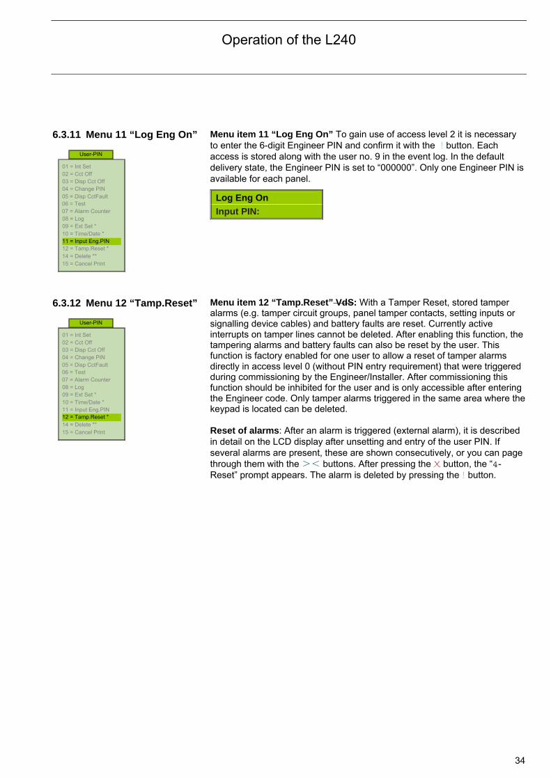
6.3.11 Menu 11 “Log Eng On”
Menu item 11 “Log Eng On” To gain use of access level 2 it is necessary to enter the 6-digit Engineer PIN and confirm it with the ! button. Each access is stored along with the user no. 9 in the event log. In the default delivery state, the Engineer PIN is set to “000000”. Only one Engineer PIN is available for each panel.
Log Eng On
Input PIN:
6.3.12 Menu 12 “Tamp.Reset”
Menu item 12 “Tamp.Reset” VdS: With a Tamper Reset, stored tamper alarms (e.g. tamper circuit groups, panel tamper contacts, setting inputs or signalling device cables) and battery faults are reset. Currently active interrupts on tamper lines cannot be deleted. After enabling this function, the tampering alarms and battery faults can also be reset by the user. This function is factory enabled for one user to allow a reset of tamper alarms directly in access level 0 (without PIN entry requirement) that were triggered during commissioning by the Engineer/Installer. After commissioning this function should be inhibited for the user and is only accessible after entering the Engineer code. Only tamper alarms triggered in the same area where thekeypad is located can be deleted. Reset of alarms: After an alarm is triggered (external alarm), it is described in detail on the LCD display after unsetting and entry of the user PIN. If several alarms are present, these are shown consecutively, or you can page through them with the >< buttons. After pressing the X button, the “4-Reset” prompt appears. The alarm is deleted by pressing the ! button.
01 = Int Set 02 = Cct Off 03 = Disp Cct Off 04 = Change PIN 05 = Disp CctFault 06 = Test 07 = Alarm Counter 08 = Log 09 = Ext Set * 10 = Time/Date * 11 = Input Eng.PIN 12 = Tamp.Reset * 14 = Delete ** 15 = Cancel Print
User-PIN
01 = Int Set 02 = Cct Off 03 = Disp Cct Off 04 = Change PIN 05 = Disp CctFault 06 = Test 07 = Alarm Counter 08 = Log 09 = Ext Set * 10 = Time/Date * 11 = Input Eng.PIN 12 = Tamp.Reset * 14 = Delete ** 15 = Cancel Print
User-PIN
Operation by the Engineer
35
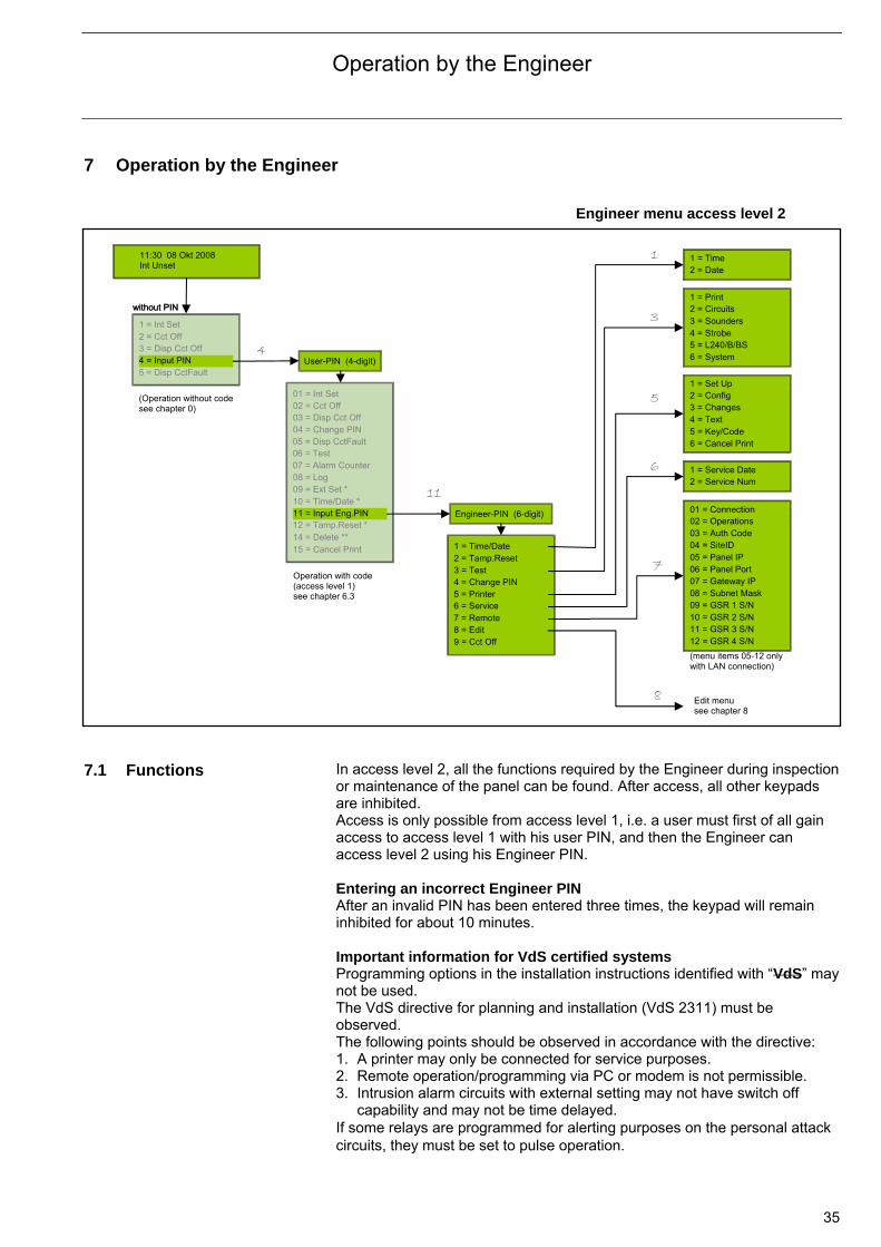
7 Operation by the Engineer
7.1 Functions In access level 2, all the functions required by the Engineer during inspection
or maintenance of the panel can be found. After access, all other keypads are inhibited. Access is only possible from access level 1, i.e. a user must first of all gain access to access level 1 with his user PIN, and then the Engineer can access level 2 using his Engineer PIN. Entering an incorrect Engineer PIN After an invalid PIN has been entered three times, the keypad will remain inhibited for about 10 minutes. Important information for VdS certified systems Programming options in the installation instructions identified with “VdS” may not be used. The VdS directive for planning and installation (VdS 2311) must be observed. The following points should be observed in accordance with the directive: 1. A printer may only be connected for service purposes. 2. Remote operation/programming via PC or modem is not permissible. 3. Intrusion alarm circuits with external setting may not have switch off
capability and may not be time delayed. If some relays are programmed for alerting purposes on the personal attack circuits, they must be set to pulse operation.
Engineer menu access level 2
Engineer-PIN (6-digit)
1 = Time/Date 2 = Tamp.Reset3 = Test4 = Change PIN5 = Printer6 = Service7 = Remote8 = Edit9 = Cct Off
1 = Time 2 = Date
1 = Print 2 = Circuits 3 = Sounders
6 = System 5 = L240/B/BS 4 = Strobe
1 = Set Up 2 = Config 3 = Changes
5 = Key/Code 4 = Text
1 = Service Date 2 = Service Num
01 = Connection 02 = Operations 03 = Auth Code 04 = SiteID
08 = Subnet Mask 07 = Gateway IP 06 = Panel Port 05 = Panel IP
12 = GSR 4 S/N 11 = GSR 3 S/N 10 = GSR 2 S/N 09 = GSR 1 S/N
(menu items 05-12 only with LAN connection)
11:30 08 Okt 2008 Int Unset
without PIN
User-PIN (4-digit) 4
11
Edit menu see chapter 8
1
3
5
6
7
8
Operation with code (access level 1) see chapter 6.3
(Operation without code see chapter 0)
without PIN
1 = Int Set 2 = Cct Off 3 = Disp Cct Off 4 = Input PIN 5 = Disp CctFault
01 = Int Set 02 = Cct Off 03 = Disp Cct Off 04 = Change PIN 05 = Disp CctFault 06 = Test 07 = Alarm Counter08 = Log 09 = Ext Set * 10 = Time/Date * 11 = Input Eng.PIN 12 = Tamp.Reset * 14 = Delete ** 15 = Cancel Print
6 = Cancel Print
Operation by the Engineer
36
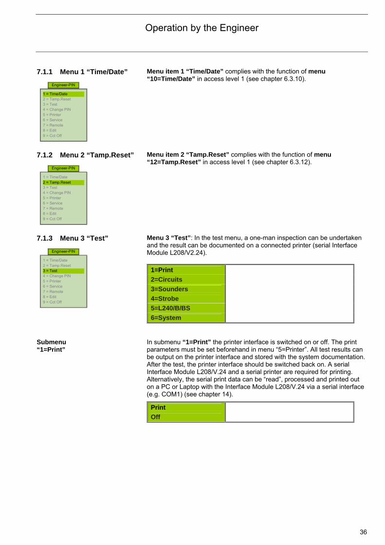
7.1.1 Menu 1 “Time/Date”
Menu item 1 “Time/Date” complies with the function of menu “10=Time/Date” in access level 1 (see chapter 6.3.10).
7.1.2 Menu 2 “Tamp.Reset”
Menu item 2 “Tamp.Reset” complies with the function of menu “12=Tamp.Reset” in access level 1 (see chapter 6.3.12).
7.1.3 Menu 3 “Test”
Menu 3 “Test”: In the test menu, a one-man inspection can be undertaken and the result can be documented on a connected printer (serial Interface Module L208/V2.24).
1=Print
2=Circuits
3=Sounders
4=Strobe
5=L240/B/BS
6=System Submenu “1=Print”
In submenu “1=Print” the printer interface is switched on or off. The print parameters must be set beforehand in menu “5=Printer”. All test results can be output on the printer interface and stored with the system documentation. After the test, the printer interface should be switched back on. A serial Interface Module L208/V.24 and a serial printer are required for printing. Alternatively, the serial print data can be “read”, processed and printed out on a PC or Laptop with the Interface Module L208/V.24 via a serial interface (e.g. COM1) (see chapter 14).
Off
Engineer-PIN
1 = Time/Date 2 = Tamp.Reset 3 = Test 4 = Change PIN 5 = Printer 6 = Service 7 = Remote 8 = Edit 9 = Cct Off
Engineer-PIN
1 = Time/Date 2 = Tamp.Reset 3 = Test 4 = Change PIN 5 = Printer 6 = Service 7 = Remote 8 = Edit 9 = Cct Off
Engineer-PIN
1 = Time/Date 2 = Tamp.Reset 3 = Test 4 = Change PIN 5 = Printer 6 = Service 7 = Remote 8 = Edit 9 = Cct Off
Operation by the Engineer
37
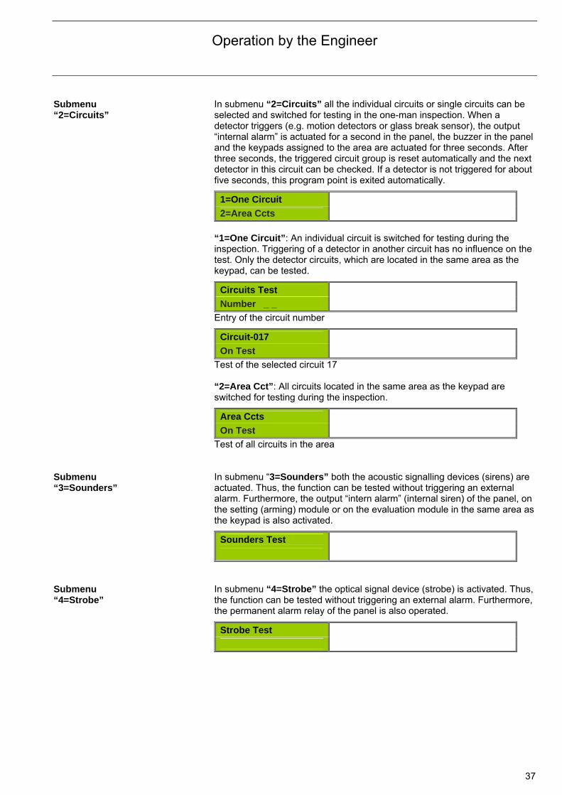
Submenu “2=Circuits”
In submenu “2=Circuits” all the individual circuits or single circuits can be selected and switched for testing in the one-man inspection. When a detector triggers (e.g. motion detectors or glass break sensor), the output “internal alarm” is actuated for a second in the panel, the buzzer in the panel and the keypads assigned to the area are actuated for three seconds. After three seconds, the triggered circuit group is reset automatically and the next detector in this circuit can be checked. If a detector is not triggered for about five seconds, this program point is exited automatically.
1=One Circuit
2=Area Ccts
“1=One Circuit”: An individual circuit is switched for testing during the inspection. Triggering of a detector in another circuit has no influence on the test. Only the detector circuits, which are located in the same area as the keypad, can be tested.
Circuits Test
Number _ _
Entry of the circuit number
Circuit-017
On Test
Test of the selected circuit 17 “2=Area Cct”: All circuits located in the same area as the keypad are switched for testing during the inspection.
Area Ccts
On Test
Test of all circuits in the area Submenu “3=Sounders”
In submenu “3=Sounders” both the acoustic signalling devices (sirens) are actuated. Thus, the function can be tested without triggering an external alarm. Furthermore, the output “intern alarm” (internal siren) of the panel, on the setting (arming) module or on the evaluation module in the same area as the keypad is also activated.
Sounders Test
Submenu “4=Strobe”
In submenu “4=Strobe” the optical signal device (strobe) is activated. Thus,the function can be tested without triggering an external alarm. Furthermore, the permanent alarm relay of the panel is also operated.
Strobe Test

Operation by the Engineer
38
Submenu “5=L240/B/BS”
In submenu “5=L240/B/BS” the setting unit (evaluation module L240/BS) can be tested, without the Intrusion Alarm Panel being in the ready to set state.
Test of an Evaluation Module L240/BS: See product manual “SafeKey Evaluation Module L240/BS”.
L240/B/BS
On Test Submenu “6=System”
In submenu “6=System” a battery or power supply test can be undertaken.
1=Check Battery
2=PSU Voltage
Battery Test, after a short wait, the “All OK” message should appear.
Battery Test
All OK
The voltage should be greater than 14.2 V with a power supply unit test.
PSU Voltage
14.408V 7.1.4 Menu 04 “Change PIN”
Menu item “4=Change PIN”: The factory Engineer PIN “000000” can be changed to a 6-digit Engineer PIN code. The new Engineer PIN code may not correspond with the management PIN code for the Evaluation Module L240/BS. The factory set Engineer PIN code should be changed immediately as it may be known to the users (e.g. from the manual).
Old PIN
Input PIN:
Enter the current Engineer PIN and press button !
New PIN
Input PIN:
Enter the new Engineer PIN and press button !
Re-enter PIN
Input PIN:
Enter the new Engineer PIN again and press button !
Engineer-PIN
1 = Time/Date 2 = Tamp.Reset 3 = Test 4 = Change PIN 5 = Printer 6 = Service 7 = Remote 8 = Edit 9 = Cct Off

Operation by the Engineer
39
7.1.5 Menu 5 “Printer”
Menu item “5=Printer”: The complete configuration of the Intrusion Alarm Panel (incl. the SafeKey chip key/keypad code) can be printed out, and the print parameters can be set. A serial Interface Module L208/V.24 and a serial printer are required for printing. Alternatively, the serial print data can be “read”, processed and printed out on a PC or Laptop with the Interface Module L208/V.24 via a serial interface (e.g. COM1) (see chapter 14.4 “Serial connection”).
1=Set Up
2=Config
3=Changes
4=Text
5=Key/Code
6=Cancel Print Submenu “1=Set Up” In submenu “1=Set Up” the print parameters for the serial print out are set.
Further information (e.g. Addressing or Settings) can be found in the see chapter 14.4 “Serial connection”.
Baud rate The selected baud rate must correspond with the set baud rate of the printer or PC/Laptop.
Printer
Baud-9600 Display and selection of the baud rate
Real Time The parameter can be activated if the printer is always in service (Real Time) and all data stored in the event log should also be printed out.
Printer
Real Time-Off Enable Real Time: Parameter=ON Submenu “2=Config”
In submenu “2=Config” the entire system configuration and programming can be printed out (incl. connected hardware, users, properties of the circuits and Evaluation Modules L240/BS).
Printing
X=Cancel Submenu “3=Changes”
In submenu “3=Changes” only the modified programming is printed out.
Printing
X=Cancel Submenu “4=Text”
In submenu “4=Text” all stored text for the circuits, user PIN codes, keypad codes/chip keys and Evaluation Modules L240/BS is printed out.
Printing Text
X=Cancel
Engineer-PIN
1 = Time/Date 2 = Tamp.Reset 3 = Test 4 = Change PIN 5 = Printer 6 = Service 7 = Remote 8 = Edit 9 = Cct Off

Operation by the Engineer
40
Submenu “5=Key/Code”
In submenu “5=Key/Code” the authorizations (e.g. access, setting/unsetting) for the keypad code or chips key and the Evaluation Module L240/BS can be printed out. This module is only available if at least one Evaluation Module L240/BS is registered. Further information relating to printing can be found in the product manual “SafeKey Evaluation Module L240/BS”.
7.1.6 Menu 6 “Printer”
Menu item “6=Service”: In the service menu, the dates and telephone number of the Engineer/Installer for the next maintenance/inspection can be entered. The service display has an influence on the function of the Intrusion Alarm System.
1=Service Date
2=Service Num
On the corresponding day the stored service telephone number appears on the display:
Service Num
0815/4711
The service note is no longer displayed on the following day or after an Engineer code is entered.
Submenu “1=Service Date”
In submenu “1=Service Date set to” the service date can be entered by pressing the button.
Serv.Date set to
Mon 20 Okt 2008 Submenu “2=Service Num”
In submenu “2=Service Tel.” the service telephone number of the Engineer/Installer can be entered.
Service Num
0
Engineer-PIN
1 = Time/Date 2 = Tamp.Reset 3 = Test 4 = Change PIN 5 = Printer 6 = Service 7 = Remote 8 = Edit 9 = Cct Off
Operation by the Engineer
41
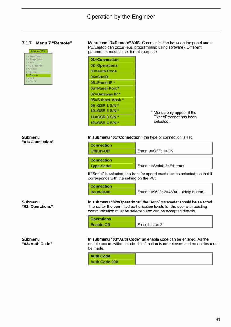
7.1.7 Menu 7 “Remote”
Menu item “7=Remote” VdS: Communication between the panel and a PC/Laptop can occur (e.g. programming using software). Different parameters must be set for this purpose.
01=Connection
02=Operations
03=Auth Code
04=SiteID
05=Panel-IP *
06=Panel-Port *
07=Gateway IP *
08=Subnet Mask *
09=GSR 1 S/N * 10=GSR 2 S/N *
11=GSR 3 S/N *
12=GSR 4 S/N * Submenu “01=Connection”
In submenu “01=Connection” the type of connection is set.
Connection
Off/On-Off Enter: 0=OFF; 1=ON
Connection
Type-Serial Enter: 1=Serial; 2=Ethernet
If “Serial” is selected, the transfer speed must also be selected, so that it corresponds with the setting on the PC:
Connection
Baud-9600 Enter: 1=9600; 2=4800… (Help button) Submenu “02=Operations”
In submenu “02=Operations” the “Auto” parameter should be selected. Thereafter the permitted authorization levels for the user with existing communication must be selected and can be accepted directly.
Operations
Enable-Off Press button 2 Submenu “03=Auth Code”
In submenu “03=Auth Code” an enable code can be entered. As the enable occurs without code, this function is not relevant and no entries must be made.
Auth Code
Auth Code-000
Engineer-PIN
1 = Time/Date 2 = Tamp.Reset 3 = Test 4 = Change PIN 5 = Printer 6 = Service 7 = Remote 8 = Edit 9 = Cct Off
* Menus only appear if the Type=Ethernet has been selected.
Operation by the Engineer
42
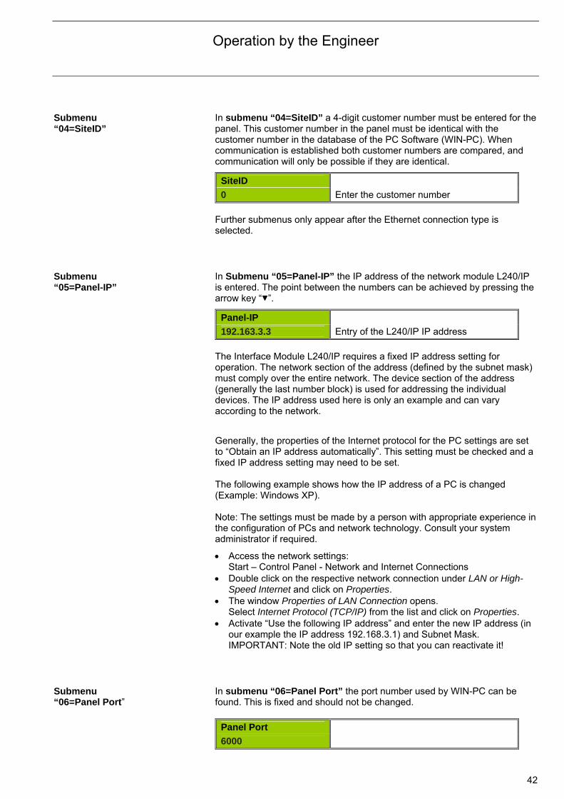
Submenu “04=SiteID”
In submenu “04=SiteID” a 4-digit customer number must be entered for the panel. This customer number in the panel must be identical with the customer number in the database of the PC Software (WIN-PC). When communication is established both customer numbers are compared, and communication will only be possible if they are identical.
SiteID
0 Enter the customer number Further submenus only appear after the Ethernet connection type is selected.
Submenu “05=Panel-IP”
In Submenu “05=Panel-IP” the IP address of the network module L240/IP is entered. The point between the numbers can be achieved by pressing the arrow key “ ”.
Panel-IP
192.163.3.3 Entry of the L240/IP IP address The Interface Module L240/IP requires a fixed IP address setting for operation. The network section of the address (defined by the subnet mask) must comply over the entire network. The device section of the address (generally the last number block) is used for addressing the individual devices. The IP address used here is only an example and can vary according to the network.
Generally, the properties of the Internet protocol for the PC settings are set to “Obtain an IP address automatically”. This setting must be checked and a fixed IP address setting may need to be set. The following example shows how the IP address of a PC is changed (Example: Windows XP). Note: The settings must be made by a person with appropriate experience in the configuration of PCs and network technology. Consult your system administrator if required.
Access the network settings: Start – Control Panel - Network and Internet Connections
Double click on the respective network connection under LAN or High-Speed Internet and click on Properties.
The window Properties of LAN Connection opens. Select Internet Protocol (TCP/IP) from the list and click on Properties.
Activate “Use the following IP address” and enter the new IP address (in our example the IP address 192.168.3.1) and Subnet Mask. IMPORTANT: Note the old IP setting so that you can reactivate it!
Submenu “06=Panel Port”
In submenu “06=Panel Port” the port number used by WIN-PC can be found. This is fixed and should not be changed.
Panel Port
6000
Operation by the Engineer
43
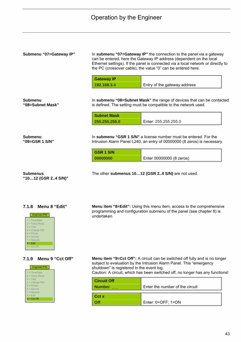
Submenu “07=Gateway IP” In submenu “07=Gateway IP” the connection to the panel via a gateway
can be entered, here the Gateway IP address (dependent on the local Ethernet settings). If the panel is connected via a local network or directly to the PC (crossover cable), the value “0” can be entered here.
Gateway IP
192.168.3.4 Entry of the gateway address Submenu “08=Subnet Mask”
In submenu “08=Subnet Mask” the range of devices that can be contacted is defined. The setting must be compatible to the network used.
Subnet Mask
255.255.255.0 Enter: 255.255.255.0 Submenu “09=GSR 1 S/N”
In submenu “GSR 1 S/N” a license number must be entered. For the Intrusion Alarm Panel L240, an entry of 00000000 (8 zeros) is necessary.
GSR 1 S/N
00000000 Enter 00000000 (8 zeros) Submenus “10…12 (GSR 2..4 S/N)”
The other submenus 10…12 (GSR 2..4 S/N) are not used.
7.1.8 Menu 8 “Edit”
Menu item “8=Edit”: Using this menu item, access to the comprehensive programming and configuration submenu of the panel (see chapter 8) is undertaken.
7.1.9 Menu 9 “Cct Off”
Menu item “9=Cct Off”: A circuit can be switched off fully and is no longer subject to evaluation by the Intrusion Alarm Panel. This “emergency shutdown” is registered in the event log. Caution: A circuit, which has been switched off, no longer has any functions!
Circuit Off
Number _ _ Enter the number of the circuit
Cct x
Off Enter: 0=OFF; 1=ON
Engineer-PIN
1 = Time/Date 2 = Tamp.Reset 3 = Test 4 = Change PIN 5 = Printer 6 = Service 7 = Remote 8 = Edit 9 = Cct Off
Engineer-PIN
1 = Time/Date 2 = Tamp.Reset 3 = Test 4 = Change PIN 5 = Printer 6 = Service 7 = Remote 8 = Edit 9 = Cct Off

Operation by the Engineer
44
8 Configuration and programming 8.1 Overview In the “Programming” submenu, the Intrusion Alarm Panel L240 can be fully
programmed by the Engineer. The panel is pre-programmed ex-works and can be immediately operated without being programmed beforehand. The changes must only be undertaken in a few of the programming steps in the corresponding submenus. The comprehensive possibilities are represented in the overview on the following page. Comfortable programming is possible with the Software “WIN-PC” and the Interface Module L208/V.24. Access to the programming level is only possible from access level 1. First of all, a user must gain access to access level 1 with his user PIN, now the Engineer can use his Engineer PIN code to use access level 2 and access the programming level via the sub menu “08=Programming”.
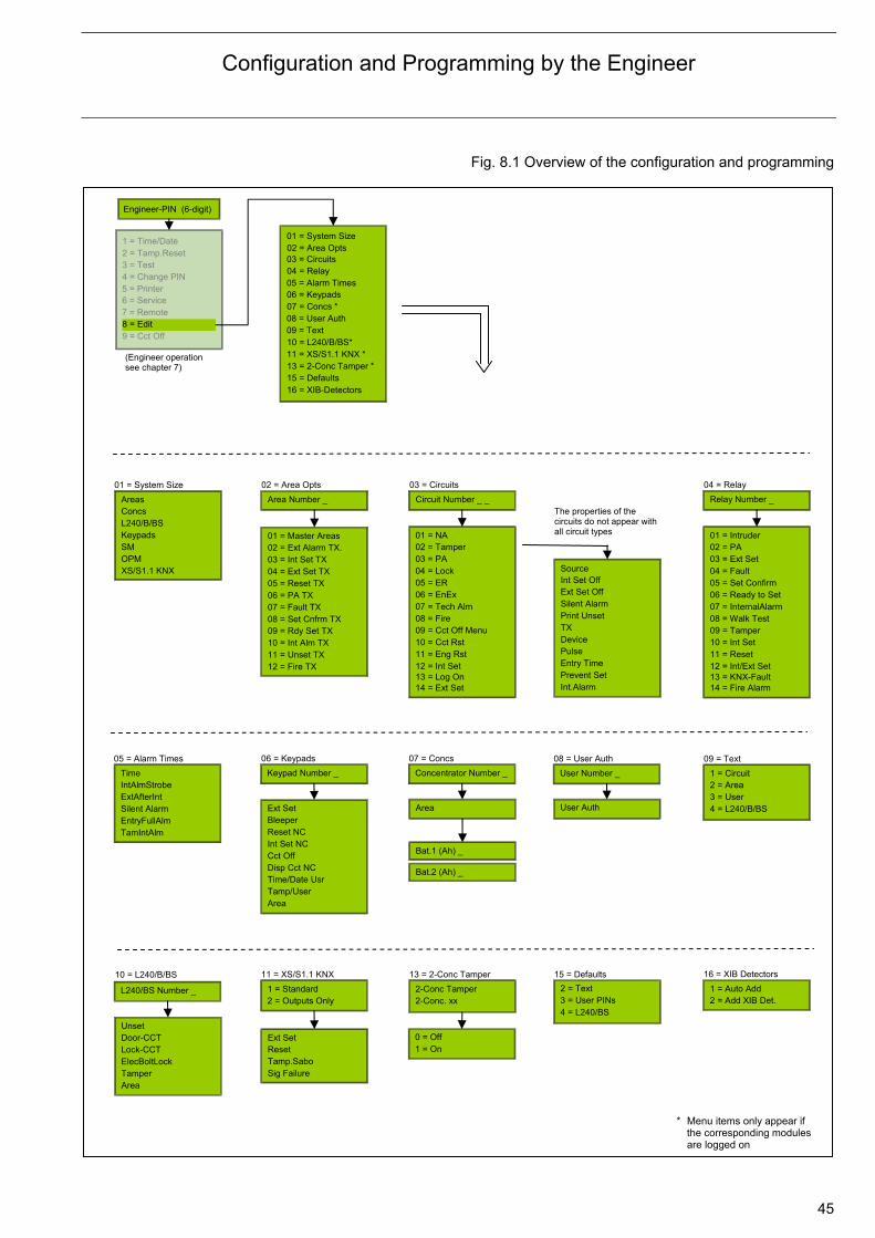
Configuration and Programming by the Engineer
45
Fig. 8.1 Overview of the configuration and programming
01 = System Size 02 = Area Opts 03 = Circuits 04 = Relay 05 = Alarm Times 06 = Keypads 07 = Concs * 08 = User Auth 09 = Text
Area Number _ Areas Concs L240/B/BS
02 = Area Opts 01 = System Size
OPM SM Keypads
1 = Standard 2 = Outputs Only
11 = XS/S1.1 KNX
01 = Master Areas 02 = Ext Alarm TX. 03 = Int Set TX 04 = Ext Set TX
08 = Set Cnfrm TX 07 = Fault TX 06 = PA TX 05 = Reset TX
12 = Fire TX 11 = Unset TX 10 = Int Alm TX 09 = Rdy Set TX
2 = Text
15 = Defaults
3 = User PINs
10 = L240/B/BS* 11 = XS/S1.1 KNX *13 = 2-Conc Tamper *15 = Defaults
01 = NA 02 = Tamper 03 = PA 04 = Lock
08 = Fire 07 = Tech Alm 06 = EnEx 05 = ER
12 = Int Set 11 = Eng Rst 10 = Cct Rst 09 = Cct Off Menu
1 = Circuit 2 = Area 3 = User
09 = Text
4 = L240/B/BS
Unset Door-CCT Lock-CCT
10 = L240/B/BS
Area Tamper ElecBoltLock
Time IntAlmStrobe ExtAfterInt
05 = Alarm Times
TamIntAlm EntryFullAlm Silent Alarm
Circuit Number _ _
03 = Circuits
Keypad Number _
06 = Keypads
Relay Number _
04 = Relay
Ext Set Bleeper Reset NC
Disp Cct NC Cct Off Int Set NC
2-Conc Tamper 2-Conc. xx
13 = 2-Conc Tamper
* Menu items only appear if the corresponding modules are logged on
XS/S1.1 KNX
14 = Ext Set 13 = Log On
01 = Intruder 02 = PA 03 = Ext Set 04 = Fault
08 = Walk Test 07 = InternalAlarm 06 = Ready to Set 05 = Set Confirm
12 = Int/Ext Set 11 = Reset 10 = Int Set 09 = Tamper
14 = Fire Alarm 13 = KNX-Fault
Area Tamp/User Time/Date Usr
Concentrator Number _
07 = Concs
User Number _
08 = User Auth
4 = L240/BS
16 = XIB-Detectors
(Engineer operation see chapter 7)
Ext Set Reset Tamp.Sabo Sig Failure
Bat.1 (Ah) _
Bat.2 (Ah) _
User Auth
0 = Off1 = On
Int Set Off Ext Set Off Silent Alarm
Device TX Print Unset
Pulse
Int.Alarm Prevent Set Entry Time
The properties of the circuits do not appear with all circuit types
Source
1 = Auto Add 2 = Add XIB Det.
16 = XIB Detectors
Engineer-PIN (6-digit)
1 = Time/Date 2 = Tamp.Reset 3 = Test 4 = Change PIN 5 = Printer 6 = Service 7 = Remote 8 = Edit 9 = Cct Off
Area
L240/BS Number _
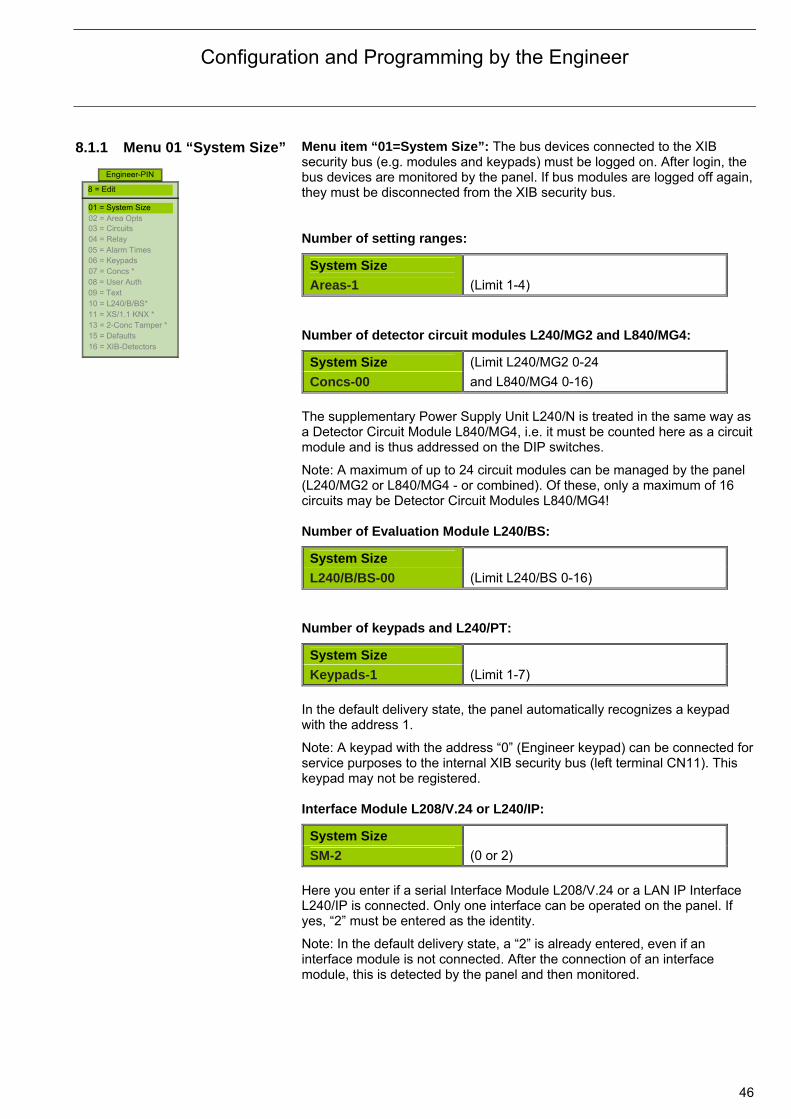
Configuration and Programming by the Engineer
46
8.1.1 Menu 01 “System Size”
Menu item “01=System Size”: The bus devices connected to the XIB security bus (e.g. modules and keypads) must be logged on. After login, the bus devices are monitored by the panel. If bus modules are logged off again, they must be disconnected from the XIB security bus. Number of setting ranges:
System Size
Areas-1 (Limit 1-4) Number of detector circuit modules L240/MG2 and L840/MG4:
System Size (Limit L240/MG2 0-24 Concs-00 and L840/MG4 0-16)
The supplementary Power Supply Unit L240/N is treated in the same way as a Detector Circuit Module L840/MG4, i.e. it must be counted here as a circuit module and is thus addressed on the DIP switches.
Note: A maximum of up to 24 circuit modules can be managed by the panel (L240/MG2 or L840/MG4 - or combined). Of these, only a maximum of 16 circuits may be Detector Circuit Modules L840/MG4! Number of Evaluation Module L240/BS:
System Size
L240/B/BS-00 (Limit L240/BS 0-16) Number of keypads and L240/PT:
System Size
Keypads-1 (Limit 1-7) In the default delivery state, the panel automatically recognizes a keypad with the address 1.
Note: A keypad with the address “0” (Engineer keypad) can be connected for service purposes to the internal XIB security bus (left terminal CN11). This keypad may not be registered. Interface Module L208/V.24 or L240/IP:
System Size
SM-2 (0 or 2) Here you enter if a serial Interface Module L208/V.24 or a LAN IP Interface L240/IP is connected. Only one interface can be operated on the panel. If yes, “2” must be entered as the identity.
Note: In the default delivery state, a “2” is already entered, even if an interface module is not connected. After the connection of an interface module, this is detected by the panel and then monitored.
Engineer-PIN
01 = System Size 02 = Area Opts 03 = Circuits 04 = Relay 05 = Alarm Times 06 = Keypads 07 = Concs * 08 = User Auth 09 = Text 10 = L240/B/BS* 11 = XS/1.1 KNX * 13 = 2-Conc Tamper * 15 = Defaults 16 = XIB-Detectors
8 = Edit
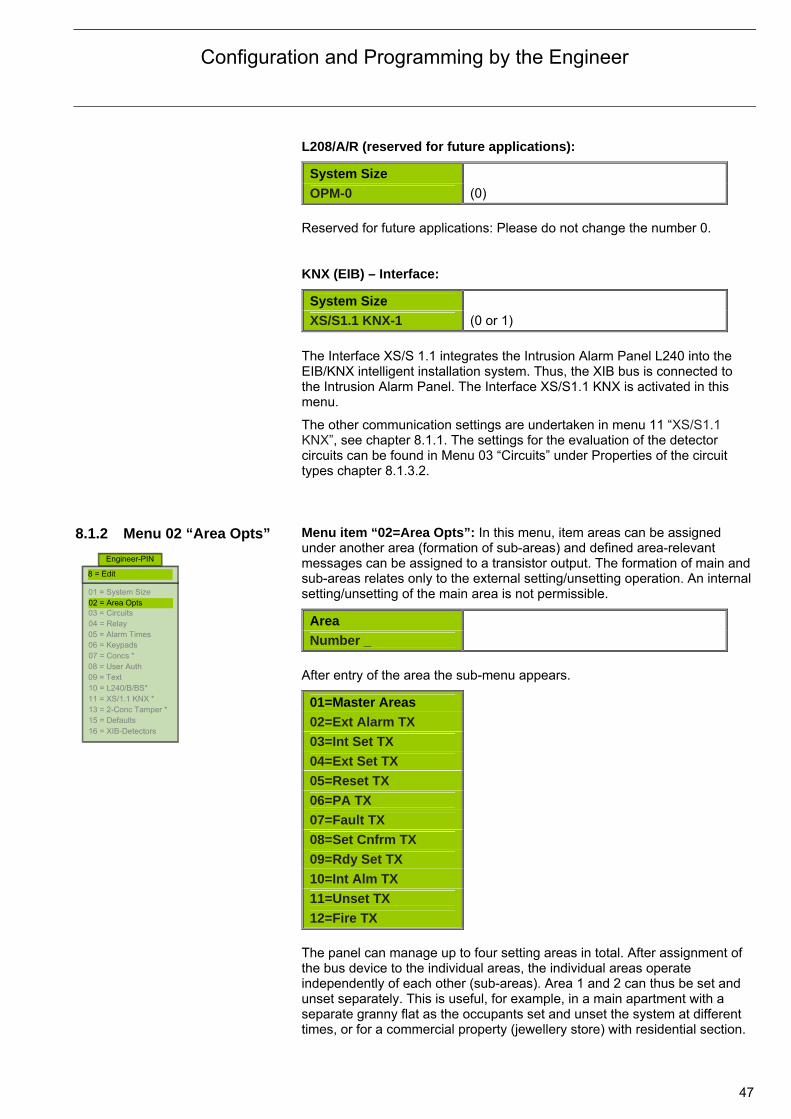
Configuration and Programming by the Engineer
47
L208/A/R (reserved for future applications):
System Size
OPM-0 (0)
Reserved for future applications: Please do not change the number 0. KNX (EIB) – Interface:
System Size
XS/S1.1 KNX-1 (0 or 1) The Interface XS/S 1.1 integrates the Intrusion Alarm Panel L240 into the EIB/KNX intelligent installation system. Thus, the XIB bus is connected to the Intrusion Alarm Panel. The Interface XS/S1.1 KNX is activated in this menu.
The other communication settings are undertaken in menu 11 “XS/S1.1 KNX”, see chapter 8.1.1. The settings for the evaluation of the detector circuits can be found in Menu 03 “Circuits” under Properties of the circuit types chapter 8.1.3.2.
8.1.2 Menu 02 “Area Opts”
Menu item “02=Area Opts”: In this menu, item areas can be assigned under another area (formation of sub-areas) and defined area-relevant messages can be assigned to a transistor output. The formation of main and sub-areas relates only to the external setting/unsetting operation. An internal setting/unsetting of the main area is not permissible.
Area
Number _
After entry of the area the sub-menu appears.
01=Master Areas
02=Ext Alarm TX
03=Int Set TX
04=Ext Set TX
05=Reset TX
06=PA TX
07=Fault TX
08=Set Cnfrm TX
09=Rdy Set TX
10=Int Alm TX
11=Unset TX
12=Fire TX
The panel can manage up to four setting areas in total. After assignment of the bus device to the individual areas, the individual areas operate independently of each other (sub-areas). Area 1 and 2 can thus be set and unset separately. This is useful, for example, in a main apartment with a separate granny flat as the occupants set and unset the system at different times, or for a commercial property (jewellery store) with residential section.
Engineer-PIN
01 = System Size 02 = Area Opts 03 = Circuits 04 = Relay 05 = Alarm Times 06 = Keypads 07 = Concs * 08 = User Auth 09 = Text 10 = L240/B/BS* 11 = XS/1.1 KNX * 13 = 2-Conc Tamper * 15 = Defaults 16 = XIB-Detectors
8 = Edit
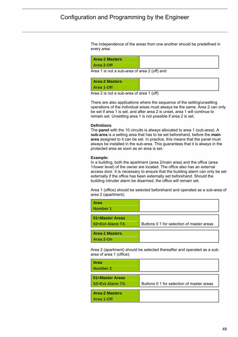
Configuration and Programming by the Engineer
48
The independence of the areas from one another should be predefined in every area:
Area-1 Masters
Area 2-Off
Area 1 is not a sub-area of area 2 (off) and
Area-2 Masters
Area 1-Off
Area 2 is not a sub-area of area 1 (off) There are also applications where the sequence of the setting/unsetting operations of the individual areas must always be the same. Area 2 can only be set if area 1 is set, and after area 2 is unset, area 1 will continue to remain set. Unsetting area 1 is not possible if area 2 is set. Definitions The panel with the 10 circuits is always allocated to area 1 (sub-area). A sub-area is a setting area that has to be set beforehand, before the main area assigned to it can be set. In practice, this means that the panel must always be installed in the sub-area. This guarantees that it is always in the protected area as soon as an area is set. Example: In a building, both the apartment (area 2/main area) and the office (area 1/lower level) of the owner are located. The office also has an external access door. It is necessary to ensure that the building alarm can only be set externally if the office has been externally set beforehand. Should the building intruder alarm be disarmed, the office will remain set. Area 1 (office) should be selected beforehand and operated as a sub-area of area 2 (apartment):
Area
Number 1
01=Master Areas
02=Ext Alarm TX. Buttons 0 1 for selection of master areas
Area-1 Masters
Area 2-On
Area 2 (apartment) should be selected thereafter and operated as a sub-area of area 1 (office):
Area
Number 2
01=Master Areas
02=Ext Alarm TX. Buttons 0 1 for selection of master areas
Area-2 Masters
Area 1-Off

Configuration and Programming by the Engineer
49
The apartment (area 2/main area) can only be set if the office (area 1/sub-area) has been set. This ensures that setting of the office area cannot be forgotten when leaving the building. On returning home the apartment must be unset and only then can the office be unset. Deleting the dependencies of the areas is undertaken in the respective area menus (enter with button “0” or Off). Assignment of area-relevant messages If different areas have been introduced, there is often a demand to differentiate between messages and signals from the individual areas and to transfer them to a control centre. In the following sub-menus, different messages (e.g. external setting area 2) to one of the transistor outputs 11-18 can be programmed for this purpose. Accordingly, one channel of a transmission device can be used. The outputs can also be used for other control functions.
For each area the following signals are available: External alarm Internal alarm External set Reset (pulse) Personal attack Fault Setting (arming) acknowledgement Ready to set Internal alarm Unset Fire alarm Example: The internal alarm for area 2 should be programmed to transistor output 7. In menu item “02=Area Opts” area 2 and the sub-menu “10=Int Alm TX“ should be selected:
Area
Number 2 Press button 2
10=Int Alm TX
11=Unset TX Press buttons 1 0
Area-2 Int Alm
TX-7 Select output 7
Area-2 Int Alm
Device-0 Press button 0 (central outputs)
Area-2 Int Alm
Invert-Off Press button 0 for Off (Invert Off) Now when there is an internal alarm from area 2, transistor 7 (terminal 17) will switch.
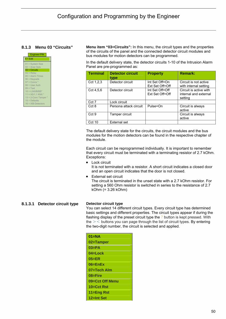
Configuration and Programming by the Engineer
50
8.1.3 Menu 03 “Circuits”
Menu item “03=Circuits”: In this menu, the circuit types and the properties of the circuits of the panel and the connected detector circuit modules and bus modules for motion detectors can be programmed.
In the default delivery state, the detector circuits 1-10 of the Intrusion Alarm Panel are pre-programmed as:
Terminal Detector circuit type
Property Remark:
Cct 1,2,3 Detector circuit Int Set Off=On Ext Set Off=Off
Circuit is not active with internal setting
Cct 4,5,6 Detector circuit Int Set Off=Off Ext Set Off=Off
Circuit is active with internal and external setting
Cct 7 Lock circuit Cct 8 Persona attack circuit Pulse=On Circuit is always
active Cct 9 Tamper circuit Circuit is always
active Cct 10 External set
The default delivery state for the circuits, the circuit modules and the bus modules for the motion detectors can be found in the respective chapter of the module. Each circuit can be reprogrammed individually. It is important to remember that every circuit must be terminated with a terminating resistor of 2.7 kOhm.Exceptions:
Lock circuit It is not terminated with a resistor. A short circuit indicates a closed door and an open circuit indicates that the door is not closed.
External set circuit The circuit is terminated in the unset state with a 2.7 kOhm resistor. For setting a 560 Ohm resistor is switched in series to the resistance of 2.7 kOhm (= 3.26 kOhm)
8.1.3.1 Detector circuit type Detector circuit type
You can select 14 different circuit types. Every circuit type has determined basic settings and different properties. The circuit types appear if during the flashing display of the preset circuit type the ? button is kept pressed. With the >< buttons you can page through the list of circuit types. By entering the two-digit number, the circuit is selected and applied.
01=NA
02=Tamper
03=PA
04=Lock
05=ER
06=EnEx
07=Tech Alm
08=Fire
09=Cct Off Menu
10=Cct Rst
11=Eng Rst
12=Int Set
Engineer-PIN
01 = System Size 02 = Area Opts 03 = Circuits 04 = Relay 05 = Alarm Times 06 = Keypads 07 = Concs * 08 = User Auth 09 = Text 10 = L240/B/BS* 11 = XS/1.1 KNX * 13 = 2-Conc Tamper * 15 = Defaults 16 = XIB-Detectors
8 = Edit

Configuration and Programming by the Engineer
51
13=Log On
14=Ext Set Intrusion circuit “01=NA”
Intrusion circuit “01=NA” On an intrusion circuit the sensors and contacts for exterior surveillance (e.g. magnetic reed contacts or glass break sensors) and monitoring of the interior (motion detectors) are connected. The circuits for motion detectors are switched off with internal setting (occupants can move freely through the building without triggering an internal alarm). Reaction to a circuit fault: Unset
Display (criteria) of the faulty circuit after a setting attempt.
Internal set: – The output “Internal alarm“, the buzzer in the panel and in the
keypads are actuated for 180 seconds (if the circuit is not switched off with internal setting).
– The LED flashes on the keypad.
After unsetting: – The output “Internal alarm”, the buzzer in the panel and in the
keypads are switched off. – On the keypad, the triggered circuit is shown for 4 seconds in the
display and then the reset request is displayed. The LED “Unset”, “Alarm circuit” and “Signal” light up.
After a reset: – The stored alarms are deleted. – The time/date and “Unset” are shown on the keypad in the display.
External set: – The output “Intruder” and the sirens are actuated for 180 seconds – The strobe and the permanent alarm relay are actuated.
After unsetting: – The sirens are switched off. – The buzzer in the panel and in the keypads are actuated. – The time/date and “Unset” are shown on the keypad in the display.
The LED flashes.
After a reset: – The stored alarms are deleted. – The strobe and the permanent alarm relay are switched off. – The time/date and “Unset” are shown on the keypad in the display.
The LED lights up.

Configuration and Programming by the Engineer
52
Tamper circuit “02=Tamper” Tamper circuit “02=Tamper”
A tamper circuit is used for monitoring the enclosures of connected components. Depending on the classification of the risk, it is necessary to include the cover contact of the external sirens and the setting device in the tampering circuit. A tampering alarm may only be reset by the Engineer. Reaction to a circuit fault: Unset:
A circuit fault triggers an internal alarm and is indicated on the keypad: – On the keypad by flashing of the LED and as a display (criteria) of the
faulty circuit after a setting attempt. – The output “Internal alarm”, the buzzer in the panel and in the
keypads are actuated.
After a reset: – The output “Internal alarm”, the buzzer in the panel and in the
keypads are switched off. – The stored alarms are deleted. – The time/date and “Unset” are shown on the keypad in the display.
The LED lights up.
Internal set: – The output “Internal alarm”, the buzzer in the panel and in the
keypads are actuated for 180 seconds. – The LED flashes on the keypad.
After unsetting: – The output “Internal alarm”, the buzzer in the panel and in the
keypads are switched off. – On the keypad, the triggered circuit is shown for 4 seconds in the
display and then the reset request is displayed. The LED flashes.
After a reset: – The stored alarms are deleted. – The time/date and “Unset” are shown on the keypad in the display.
The LED lights up.
External set: – The output “Intruder” and the sirens are actuated for 180 seconds. – The strobe and the permanent alarm relay are actuated.
After unsetting: – The sirens are switched off. – The buzzer in the panel and in the keypads are actuated. – The time/date and “Unset” are shown on the keypad in the display.
The LED flashes.
After a reset: – The stored alarms are deleted. – The strobe and the permanent alarm relay are switched off. – The time/date and “Unset” are shown on the keypad in the display.
The LED lights up.

Configuration and Programming by the Engineer
53
Personal attack circuit “03=PA”
Personal attack circuit “03=PA” Panic buttons are connected to the personal attack circuit and are always set. In the default state, it will only trigger a silent alarm (output “Personal attack”). This circuit group is the only one that can trigger multiple alarms if actuated several times. In compliance with the VdS directive for planning and installation (VdS 2311), personal attack circuits must be set to pulse operation. Reaction to a circuit fault: Unset:
– The “Personal Attack” output is actuated for 180 seconds. – On the keypad, the LED flashes and as an indication (criteria) the
faulty circuit after a setting attempt.
After a reset: – The stored alarms are deleted. – The time/date and “Unset” are shown on the keypad in the display.
The LED lights up.
Internal set: – The “Personal Attack” output is actuated for 180 seconds. – The LED flashes on the keypad.
After unsetting: – The output “Personal Attack” is switched off. – On the keypad, the triggered circuit is shown for 4 seconds in the
display and then the reset request is displayed. The LED flashes.
After a reset: – The stored alarms are deleted. – The time/date and “Unset” are shown on the keypad in the display.
The LED lights up.
External set: – The “Personal Attack” output is actuated for 180 seconds.
After unsetting: – The buzzer in the panel and in the keypads are actuated. – The time/date and “Unset” are shown on the keypad in the display.
The LED flashes.
After a reset: – The stored alarms are deleted. – The time/date and “Unset” are shown on the keypad in the display.
The LED lights up.
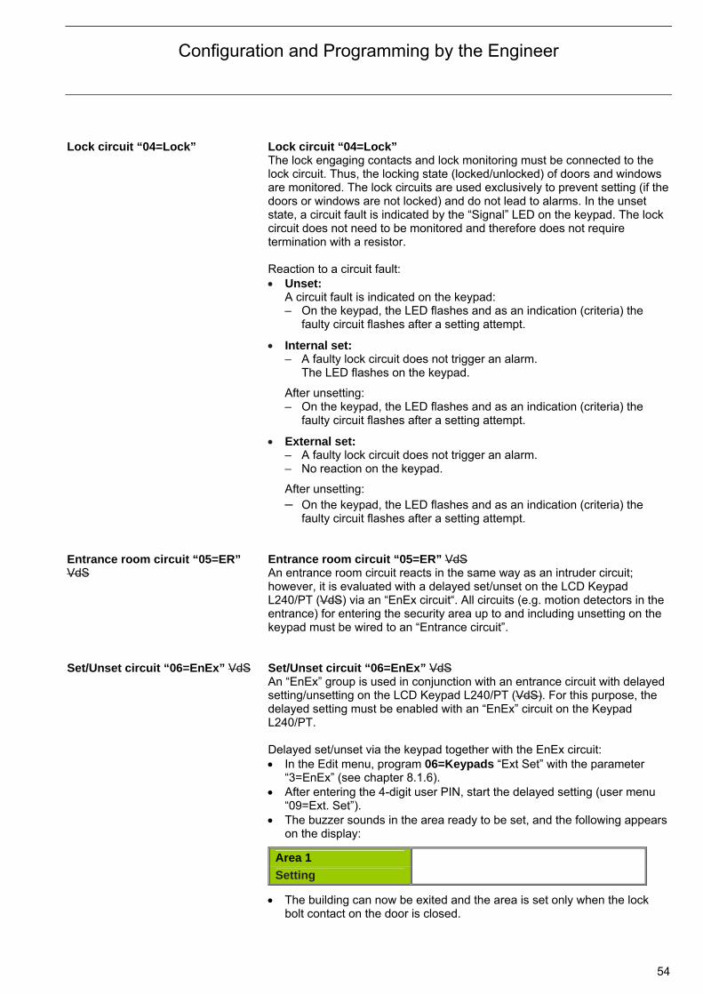
Configuration and Programming by the Engineer
54
Lock circuit “04=Lock” Lock circuit “04=Lock”
The lock engaging contacts and lock monitoring must be connected to the lock circuit. Thus, the locking state (locked/unlocked) of doors and windows are monitored. The lock circuits are used exclusively to prevent setting (if the doors or windows are not locked) and do not lead to alarms. In the unset state, a circuit fault is indicated by the “Signal” LED on the keypad. The lock circuit does not need to be monitored and therefore does not require termination with a resistor. Reaction to a circuit fault: Unset:
A circuit fault is indicated on the keypad: – On the keypad, the LED flashes and as an indication (criteria) the
faulty circuit flashes after a setting attempt.
Internal set: – A faulty lock circuit does not trigger an alarm.
The LED flashes on the keypad.
After unsetting: – On the keypad, the LED flashes and as an indication (criteria) the
faulty circuit flashes after a setting attempt.
External set: – A faulty lock circuit does not trigger an alarm. – No reaction on the keypad.
After unsetting: – On the keypad, the LED flashes and as an indication (criteria) the
faulty circuit flashes after a setting attempt. Entrance room circuit “05=ER” VdS
Entrance room circuit “05=ER” VdS An entrance room circuit reacts in the same way as an intruder circuit; however, it is evaluated with a delayed set/unset on the LCD Keypad L240/PT (VdS) via an “EnEx circuit“. All circuits (e.g. motion detectors in the entrance) for entering the security area up to and including unsetting on the keypad must be wired to an “Entrance circuit”.
Set/Unset circuit “06=EnEx” VdS Set/Unset circuit “06=EnEx” VdS
An “EnEx” group is used in conjunction with an entrance circuit with delayed setting/unsetting on the LCD Keypad L240/PT (VdS). For this purpose, the delayed setting must be enabled with an “EnEx” circuit on the Keypad L240/PT. Delayed set/unset via the keypad together with the EnEx circuit: In the Edit menu, program 06=Keypads “Ext Set” with the parameter
“3=EnEx” (see chapter 8.1.6). After entering the 4-digit user PIN, start the delayed setting (user menu
“09=Ext. Set”). The buzzer sounds in the area ready to be set, and the following appears
on the display:
Area 1
Setting
The building can now be exited and the area is set only when the lock bolt contact on the door is closed.

Configuration and Programming by the Engineer
55
If someone enters the building and the EnEx circuit is opened by the lock bolt contact, the entrance time will start. During this time, the buzzer on the keypad sounds and an entrance circuit (e.g. motion detector in the entrance area) may indicate a fault without triggering an alarm.
Unsetting is undertaken on the keypad by entering the user PIN.
Delayed set/unset via the keypad together with the EnEx circuit or after a delay time: In the Edit menu, program 06=Keypads “Ext Set” with the parameter
“4=EnEx/Tm” and enter a delay time (see chapter 8.1.6). The set/unset behaves as if there was no delay time, and after the delay
time has timed out or closing of the EnEx circuit it will be unset.
Area 1
Seconds Left-062 Technology circuit “07=Tech Alm” Technology circuit “07=Tech Alm”
On the technology circuit, technical detectors such as water detectors or gas detectors can be connected and the operators alerted in due time via an internal alarm of a selected device. In compliance with the VdS directive for planning and installation (VdS 2311), technology circuits may not be programmed to prevent setting (criteria off), i.e. a technology alarm is reported but does not lead to prevention of setting! An interrupt of the technology circuit – even in the externally set state – will not cause an external alarm. A technology circuit can be used in VdS class C systems to incorporate detected anti-masking of a motion detector into the forced setting. For this purpose, the detector circuit must be programmed as “Criterion On” and the interrupt output of the (anti-masking monitored) motion detector must be looped into this circuit.
Fire circuit “08=Fire” VdS
Fire circuit “08=Fire” VdS A fire detector can be connected to a fire circuit and the operators alerted in due time via an internal alarm of a selected device. Fire circuits are setting-preventative and may not be used on VdS certified systems. However, fire detectors can be operated in a technology circuit with the property “Criteria Off” (not setting preventative). An interruption of the fire circuit – even in the externally set state – will not cause an external alarm.
Circuit off “09=Cct Off Menu” VdS
Circuit off circuit “09=Cct Off Menu” VdS A fault of this circuit (e.g. with key switch) accommodates the immediate access to a menu where the circuits can be completely switched off. This “emergency shutdown” is also registered in the event log.
Circuit Off
Number _ _ Reset circuit “10=Cct Rst” VdS
Reset circuit “10=Cct Rst” VdS A brief interrupt of this group (e.g. with a key switch) causes the stored alarms (e.g. internal, intrusion or personal attack alarms) to be deleted. A tampering alarm cannot be deleted.

Configuration and Programming by the Engineer
56
Tamper reset circuit “11=Eng Rst” VdS
Tamper reset circuit “11=Eng Rst” VdS A brief interrupt of this group (e.g. with a key switch) causes the stored alarms (e.g. internal, intrusion or personal attack alarms) to be deleted including a tampering alarm.
Internal set circuit “12=Int Set”
Internal set circuit “12=Int Set” An internal set circuit switches the area internally set/unset. It is programmable for button mode (pulse on) or switch mode (pulse off). For button mode (recommended), touch contacts can be connected and with every transition from interrupted to non-operation (terminated with 2.7 kOhm) switch over occurs. In switch mode, an interrupted circuit corresponds with internal set and a non-operational circuit (terminated with 2.7 kOhm) is unset.
User code circuit “13=Log On”
User code circuit “13=Log On” A brief interruption of this group (e.g. with a key switch) has the same effect as the entry of a valid 4-digit user PIN on Keypad L240/PT. Access to the user level (access level 1) is enabled. The activation of this user code circuit is stored in the event log as “Code-Cct on”.
External set circuit “14=Ext Set” External set circuit “14=Ext Set”
An external set circuit switches the area externally set/unset. It should be programmed for switch mode (pulse off) (button mode not supported). This option applies for the circuit inputs on the main circuit board. Conventional setting (arming) contacts can be connected. In switch mode, the circuit is terminated in the unset state with a 2.7 kOhm resistor. For setting purposes, a 560 Ohm resistor is switched in series to the 2.7 kOhm resistor (= 3.26 kOhm). In this way not only the set/unset states but also the short circuit/open circuit states are monitored. An interrupted circuit (except 2.7 kOhm or 3.26 kOhm) causes a “Tamper setting” alarm.
8.1.3.2 Properties of the
circuit types
Properties of the circuit types These appear if during the flashing display of the preset circuit button < is pressed or after another circuit type has been selected and accepted. Using button ? you can call up further information. The properties are dependent on the circuit and do not appear for all circuit types (bold=factory default setting).
Source Circuit-0xx
Source-Standard 1=Standard; 2=EIB/KNX The selection Standard ensures no access from the KNX to the circuit. The L240 “wired” circuit is evaluated. The selection EIB/KNX enables access from the KNX to the circuit, i.e. only the KNX circuit is evaluated, the L240 “wired” circuit is not evaluated.
Circuit-0xx
Area-1 1 to 4
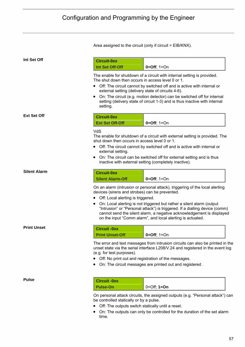
Configuration and Programming by the Engineer
57
Area assigned to the circuit (only if circuit = EIB/KNX). Int Set Off Circuit-0xx
Int Set Off-Off 0=Off; 1=On
The enable for shutdown of a circuit with internal setting is provided. The shut down then occurs in access level 0 or 1. Off: The circuit cannot by switched off and is active with internal or
external setting (delivery state of circuits 4-6). On: The circuit (e.g. motion detector) can be switched off for internal
setting (delivery state of circuit 1-3) and is thus inactive with internal setting.
Ext Set Off Circuit-0xx
Ext Set Off-Off 0=Off; 1=On
VdS The enable for shutdown of a circuit with external setting is provided. The shut down then occurs in access level 0 or 1. Off: The circuit cannot by switched off and is active with internal or
external setting. On: The circuit can be switched off for external setting and is thus
inactive with external setting (completely inactive). Silent Alarm Circuit-0xx
Silent Alarm-Off 0=Off; 1=On
On an alarm (intrusion or personal attack), triggering of the local alerting devices (sirens and strobes) can be prevented.
Off: Local alerting is triggered. On: Local alerting is not triggered but rather a silent alarm (output
“Intrusion” or “Personal attack”) is triggered. If a dialling device (comm) cannot send the silent alarm, a negative acknowledgement is displayed on the input “Comm alarm”, and local alerting is actuated.
Print Unset Circuit -0xx
Print Unset-Off 0=Off; 1=On
The error and text messages from intrusion circuits can also be printed in the unset state via the serial interface L208/V.24 and registered in the event log (e.g. for test purposes).
Off: No print out and registration of the messages. On: The circuit messages are printed out and registered .
Pulse Circuit -0xx
Pulse-On 0=Off; 1=On
On personal attack circuits, the assigned outputs (e.g. “Personal attack“) can be controlled statically or by a pulse.
Off: The outputs switch statically until a reset. On: The outputs can only be controlled for the duration of the set alarm
time.

Configuration and Programming by the Engineer
58
Prevent Set Circuit -0xx
Prevent Set-On 0=Off; 1=On
Technical circuits can cause a prevention of setting on a fault.
Off: An interrupted circuit does not prevent setting. On: An interrupted circuit prevents setting.
8.1.4 Menu 04 “Relay”
Menu item “04=Relay”: Both relays on the main PCB are already pre-programmed in the factory: Relay 1 (terminals 19, 20, 21): External set (area 1). Relay 2 (terminals 22, 23, 24): Walk test. Both relays are assigned to area 1 and can be reprogrammed to the following functions:
Display Description 01=Intruder Active on an intrusion alarm for the set alarm time 02=PA Active on a personal attack alarm for the set alarm
time 03=Ext Set Active with externally set area 1 04=Fault Active with a mains/battery fault (delayed up to 15
minutes) and processor failure 05=Set Confirm Active for about 3 seconds after ext. setting of area 1 06=Ready to Set Active if area 1 ready to set 07= Internal Alarm Active with internal alarm in area 1 08=Walk Test Active with switched on walk test 09=Tamper Active with tampering alarm 10=Int Set Active with internally set area 1 11=Reset Active on a reset for about 5 seconds 12=Int/Ext Set Active with internally or externally set area 1 13=KNX-Fault Active with KNX error 14=Fire-Alarm Active when a fire circuit is triggered
Programming of a relay:
Relay
Number _ (Limit 1 or 2)
Relay-1
Ext Set (Button ? for number/selection of function)
Engineer-PIN
01 = System Size 02 = Area Opts 03 = Circuits 04 = Relay 05 = Alarm Times 06 = Keypads 07 = Concs * 08 = User Auth 09 = Text 10 = L240/B/BS* 11 = XS/1.1 KNX * 13 = 2-Conc Tamper * 15 = Defaults 16 = XIB-Detectors
8 = Edit
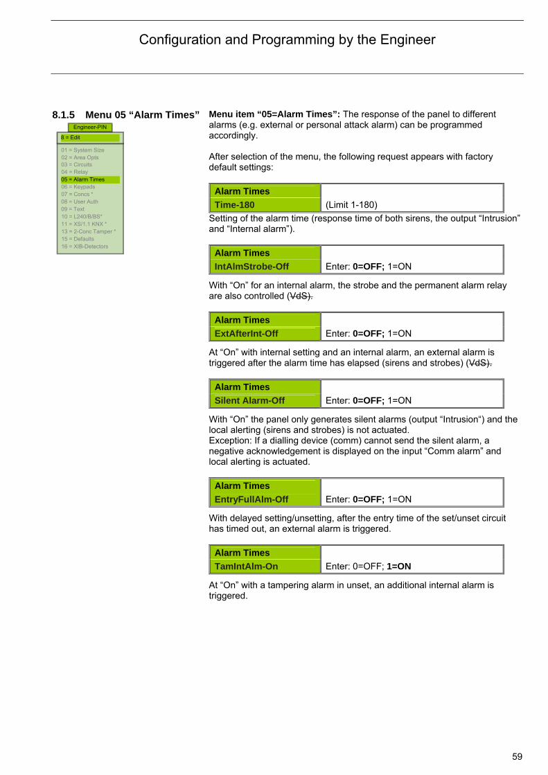
Configuration and Programming by the Engineer
59
8.1.5 Menu 05 “Alarm Times”
Menu item “05=Alarm Times”: The response of the panel to different alarms (e.g. external or personal attack alarm) can be programmed accordingly. After selection of the menu, the following request appears with factory default settings:
Alarm Times
Time-180 (Limit 1-180) Setting of the alarm time (response time of both sirens, the output “Intrusion” and “Internal alarm”).
Alarm Times
IntAlmStrobe-Off Enter: 0=OFF; 1=ON
With “On” for an internal alarm, the strobe and the permanent alarm relay are also controlled (VdS).
Alarm Times
ExtAfterInt-Off Enter: 0=OFF; 1=ON
At “On” with internal setting and an internal alarm, an external alarm is triggered after the alarm time has elapsed (sirens and strobes) (VdS).
Alarm Times
Silent Alarm-Off Enter: 0=OFF; 1=ON
With “On” the panel only generates silent alarms (output “Intrusion“) and the local alerting (sirens and strobes) is not actuated. Exception: If a dialling device (comm) cannot send the silent alarm, a negative acknowledgement is displayed on the input “Comm alarm” and local alerting is actuated.
Alarm Times
EntryFullAlm-Off Enter: 0=OFF; 1=ON
With delayed setting/unsetting, after the entry time of the set/unset circuit has timed out, an external alarm is triggered.
Alarm Times
TamIntAlm-On Enter: 0=OFF; 1=ON
At “On” with a tampering alarm in unset, an additional internal alarm is triggered.
Engineer-PIN
01 = System Size 02 = Area Opts 03 = Circuits 04 = Relay 05 = Alarm Times 06 = Keypads 07 = Concs * 08 = User Auth 09 = Text 10 = L240/B/BS* 11 = XS/1.1 KNX * 13 = 2-Conc Tamper * 15 = Defaults 16 = XIB-Detectors
8 = Edit
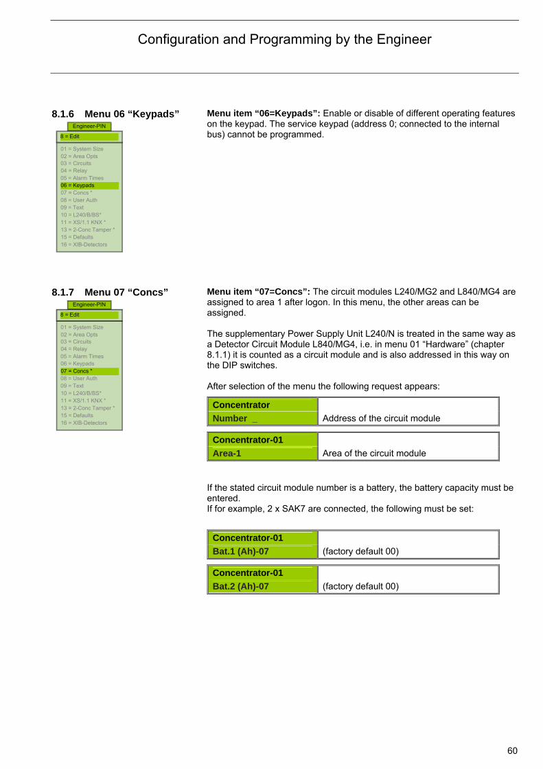
Configuration and Programming by the Engineer
60
8.1.6 Menu 06 “Keypads”
Menu item “06=Keypads”: Enable or disable of different operating features on the keypad. The service keypad (address 0; connected to the internal bus) cannot be programmed.
8.1.7 Menu 07 “Concs”
Menu item “07=Concs”: The circuit modules L240/MG2 and L840/MG4 are assigned to area 1 after logon. In this menu, the other areas can be assigned. The supplementary Power Supply Unit L240/N is treated in the same way as a Detector Circuit Module L840/MG4, i.e. in menu 01 “Hardware” (chapter 8.1.1) it is counted as a circuit module and is also addressed in this way on the DIP switches. After selection of the menu the following request appears:
Concentrator
Number _ Address of the circuit module
Concentrator-01
Area-1 Area of the circuit module If the stated circuit module number is a battery, the battery capacity must be entered. If for example, 2 x SAK7 are connected, the following must be set:
Concentrator-01
Bat.1 (Ah)-07 (factory default 00)
Concentrator-01
Bat.2 (Ah)-07 (factory default 00)
Engineer-PIN
01 = System Size 02 = Area Opts 03 = Circuits 04 = Relay 05 = Alarm Times 06 = Keypads 07 = Concs * 08 = User Auth 09 = Text 10 = L240/B/BS* 11 = XS/1.1 KNX * 13 = 2-Conc Tamper * 15 = Defaults 16 = XIB-Detectors
8 = Edit
Engineer-PIN
01 = System Size 02 = Area Opts 03 = Circuits 04 = Relay 05 = Alarm Times 06 = Keypads 07 = Concs * 08 = User Auth 09 = Text 10 = L240/B/BS* 11 = XS/1.1 KNX * 13 = 2-Conc Tamper * 15 = Defaults 16 = XIB-Detectors
8 = Edit
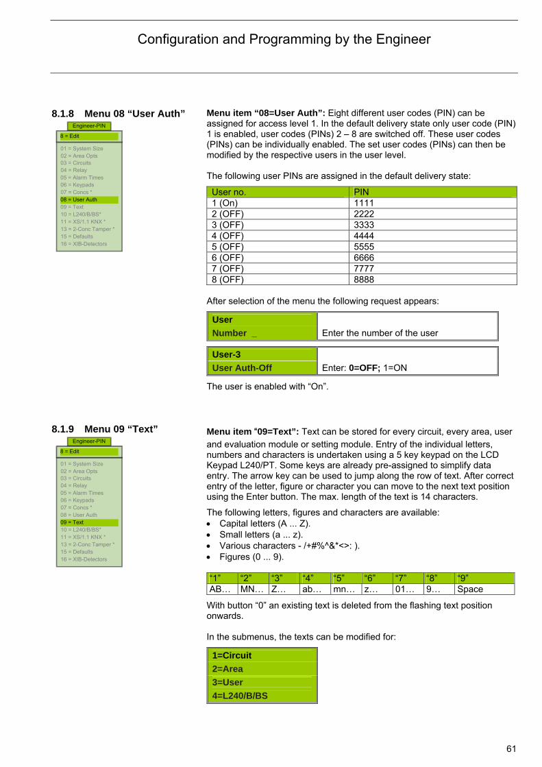
Configuration and Programming by the Engineer
61
8.1.8 Menu 08 “User Auth”
Menu item “08=User Auth”: Eight different user codes (PIN) can be assigned for access level 1. In the default delivery state only user code (PIN) 1 is enabled, user codes (PINs) 2 – 8 are switched off. These user codes (PINs) can be individually enabled. The set user codes (PINs) can then be modified by the respective users in the user level. The following user PINs are assigned in the default delivery state:
User no. PIN 1 (On) 1111 2 (OFF) 2222 3 (OFF) 3333 4 (OFF) 4444 5 (OFF) 5555 6 (OFF) 6666 7 (OFF) 7777 8 (OFF) 8888
After selection of the menu the following request appears:
User
Number _ Enter the number of the user
User-3
User Auth-Off Enter: 0=OFF; 1=ON
The user is enabled with “On”. 8.1.9 Menu 09 “Text”
Menu item “09=Text”: Text can be stored for every circuit, every area, user and evaluation module or setting module. Entry of the individual letters, numbers and characters is undertaken using a 5 key keypad on the LCD Keypad L240/PT. Some keys are already pre-assigned to simplify data entry. The arrow key can be used to jump along the row of text. After correct entry of the letter, figure or character you can move to the next text position using the Enter button. The max. length of the text is 14 characters.
The following letters, figures and characters are available: Capital letters (A ... Z). Small letters (a ... z). Various characters - /+#%^&*<>: ). Figures (0 ... 9). “1” “2” “3” “4” “5” “6” “7” “8” “9” AB… MN… Z… ab… mn… z… 01… 9… Space
With button “0” an existing text is deleted from the flashing text position onwards. In the submenus, the texts can be modified for:
1=Circuit
2=Area
3=User
4=L240/B/BS
Engineer-PIN
01 = System Size 02 = Area Opts 03 = Circuits 04 = Relay 05 = Alarm Times 06 = Keypads 07 = Concs * 08 = User Auth 09 = Text 10 = L240/B/BS* 11 = XS/1.1 KNX * 13 = 2-Conc Tamper * 15 = Defaults 16 = XIB-Detectors
8 = Edit
Engineer-PIN
01 = System Size 02 = Area Opts 03 = Circuits 04 = Relay 05 = Alarm Times 06 = Keypads 07 = Concs * 08 = User Auth 09 = Text 10 = L240/B/BS* 11 = XS/1.1 KNX * 13 = 2-Conc Tamper * 15 = Defaults 16 = XIB-Detectors
8 = Edit

Configuration and Programming by the Engineer
62
Example: Change the text for circuit 1. Select submenu “1=Cct 1”.
Circuit
Number _ _ Enter the circuit number
Circuit 1
Cct 1 (text used up to now is displayed)
The first character flashes. Using the arrow keys you can advance in the text line and jump to the next text position with the Enter button.
8.1.10 Menu 10 “L240/B/BS”
Menu item “10=L240/B/BS”: The Evaluation Module L240/BS is assigned to area 1 after it has registered. In this menu, the other areas can be assigned. Refer to chapter 12 “SafeKey Evaluation Module L240/BS.
8.1.11 Menu 11 “XS/S1.1 KNX”
Menu item “11=XS/S1.1 KNX”: The state of all 80 circuits of the panel as well as other panel states such as the setting states, the alerting and the signal devices can be monitored on the KNX system. Each of the 80 circuits can also be contacted via the KNX. At the same time, the setting can be undertaken via the KNX bus, and the alarm systems can be reset via the KNX. Every function, which allows access to the intrusion alarm system, can be inhibited individually. Communication to the KNX:
XS/S1.1 KNX
Standard (1=Standard; 2=Output Only) 1=Standard VdS: Bidirectional communication. 2=Outputs Only, the panel is inhibited in the KNX system. Enables (only with standard communication): Inhibit or enable external setting:
XS/S1.1 KNX
Ext Set-Off (0=Off;1=On)
Engineer-PIN
01 = System Size 02 = Area Opts 03 = Circuits 04 = Relay 05 = Alarm Times 06 = Keypads 07 = Concs * 08 = User Auth 09 = Text 10 = L240/B/BS* 11 = XS/1.1 KNX * 13 = 2-Conc Tamper * 15 = Defaults 16 = XIB-Detectors
8 = Edit
Engineer-PIN
01 = System Size 02 = Area Opts 03 = Circuits 04 = Relay 05 = Alarm Times 06 = Keypads 07 = Concs * 08 = User Auth 09 = Text 10 = L240/B/BS* 11 = XS/1.1 KNX * 13 = 2-Conc Tamper * 15 = Defaults 16 = XIB-Detectors
8 = Edit
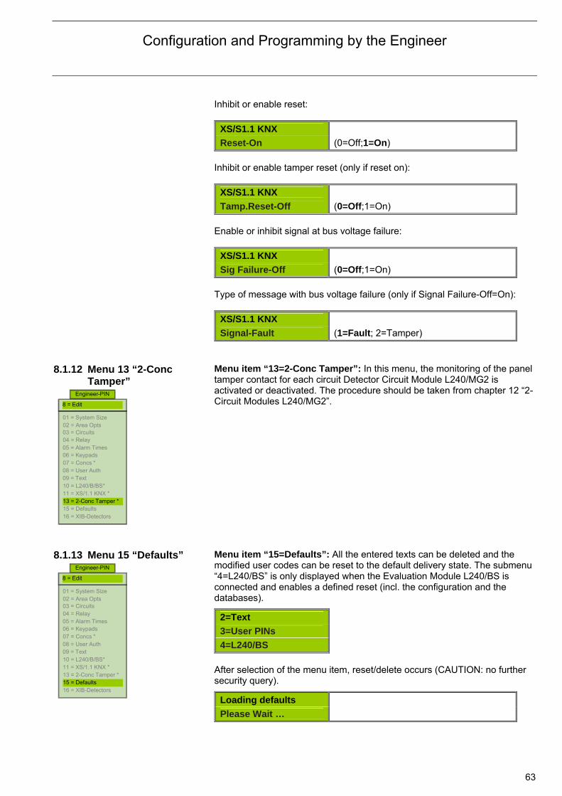
Configuration and Programming by the Engineer
63
Inhibit or enable reset:
XS/S1.1 KNX
Reset-On (0=Off;1=On) Inhibit or enable tamper reset (only if reset on):
XS/S1.1 KNX
Tamp.Reset-Off (0=Off;1=On) Enable or inhibit signal at bus voltage failure:
XS/S1.1 KNX
Sig Failure-Off (0=Off;1=On) Type of message with bus voltage failure (only if Signal Failure-Off=On):
XS/S1.1 KNX
Signal-Fault (1=Fault; 2=Tamper) 8.1.12 Menu 13 “2-Conc
Tamper”
Menu item “13=2-Conc Tamper”: In this menu, the monitoring of the panel tamper contact for each circuit Detector Circuit Module L240/MG2 is activated or deactivated. The procedure should be taken from chapter 12 “2-Circuit Modules L240/MG2”.
8.1.13 Menu 15 “Defaults”
Menu item “15=Defaults”: All the entered texts can be deleted and the modified user codes can be reset to the default delivery state. The submenu “4=L240/BS” is only displayed when the Evaluation Module L240/BS is connected and enables a defined reset (incl. the configuration and the databases).
2=Text
3=User PINs
4=L240/BS
After selection of the menu item, reset/delete occurs (CAUTION: no further security query).
Loading defaults
Please Wait …
Engineer-PIN
01 = System Size 02 = Area Opts 03 = Circuits 04 = Relay 05 = Alarm Times 06 = Keypads 07 = Concs * 08 = User Auth 09 = Text 10 = L240/B/BS* 11 = XS/1.1 KNX * 13 = 2-Conc Tamper * 15 = Defaults 16 = XIB-Detectors
8 = Edit
Engineer-PIN
01 = System Size 02 = Area Opts 03 = Circuits 04 = Relay 05 = Alarm Times 06 = Keypads 07 = Concs * 08 = User Auth 09 = Text 10 = L240/B/BS* 11 = XS/1.1 KNX * 13 = 2-Conc Tamper * 15 = Defaults 16 = XIB-Detectors
8 = Edit
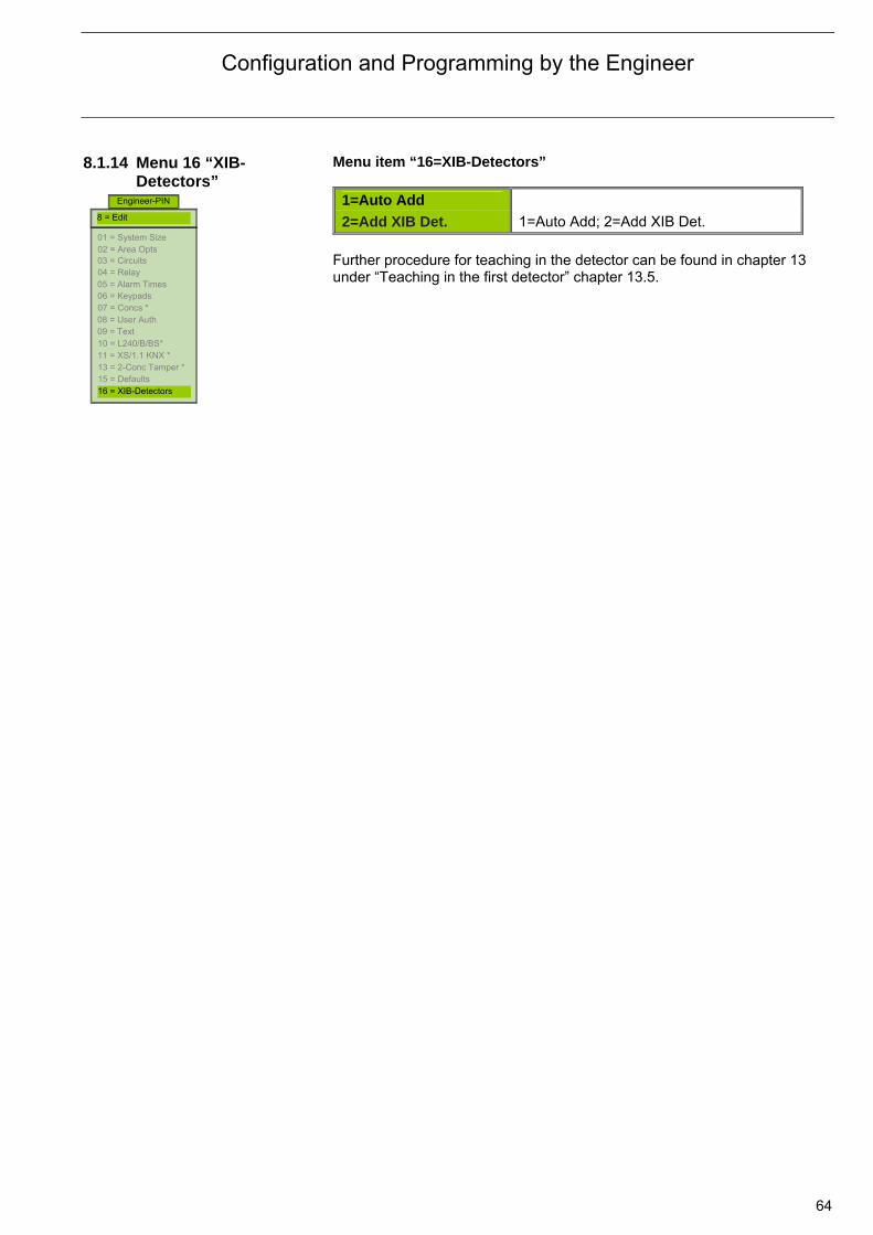
Configuration and Programming by the Engineer
64
8.1.14 Menu 16 “XIB-Detectors”
Menu item “16=XIB-Detectors”
1=Auto Add
2=Add XIB Det. 1=Auto Add; 2=Add XIB Det. Further procedure for teaching in the detector can be found in chapter 13 under “Teaching in the first detector” chapter 13.5.
Engineer-PIN
01 = System Size 02 = Area Opts 03 = Circuits 04 = Relay 05 = Alarm Times 06 = Keypads 07 = Concs * 08 = User Auth 09 = Text 10 = L240/B/BS* 11 = XS/1.1 KNX * 13 = 2-Conc Tamper * 15 = Defaults 16 = XIB-Detectors
8 = Edit

SafeKey
65
9 Management of the chip key/keypad code 9.1 General The management of all keypad codes and chip keys (e.g. learn or delete)
and their authorizations (e.g. access, set/unset operations) is undertaken on the Intrusion Alarm Panel L240 with the LCD Keypad L240/PT in the “Management” menu. The access to the “Management” menu is undertaken using the 6-digit management code on the LCD Keypad L240/PT. The code is set by factory default to “999999”. By this method of direct access without entry of a 4-digit user PIN code, the management of the keypad code and chip key is thus undertaken by the user or the Engineer of the Intrusion Alarm Panel. The management encompasses all areas and refers to the Evaluation Module L240/BS and chip key or keypad code in all security areas.
Deleting the keypad code and chip key is also possible in the user level. After entry of the 4-digit user PIN No. 1 (factory default “1111”) you access the user level and can delete the keypad code and chip key as in the menu “Management”.
Note: In order to manage the keypad codes and chip key, at least one
Evaluation Module L240/BS must be connected and logged on. For “detection” and “learning” of a keypad code or chip key,
communication between an evaluation module and door cylinder, strike plate or wall reader must be provided.
If the panel is in “learn mode”, no door can be opened from outside via a strike plate or door cylinder! However, the door can still be opened from inside by another person.
The 3-digit code/key number is necessary to change or delete the keypad code and chip key. It is assigned when learning in a keypad code or chip key by the Intrusion Alarm Panel and should be noted accordingly (e.g. in the table provided in the manual “Evaluation Module L240/BS”).
Wall reader
WEL/A Chip key WELT/A
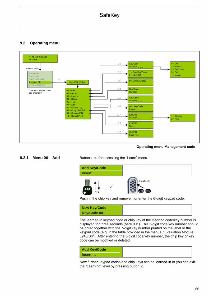
SafeKey
66
9.2 Operating menu
9.2.1 Menu 06 – Add Buttons 06 for accessing the “Learn” menu
Add Key/Code
Insert …
or Push in the chip key and remove it or enter the 6-digit keypad code.
New Key/Code
Key/Code 001
The learned-in keypad code or chip key of the inserted code/key number is displayed for three seconds (here 001). This 3-digit code/key number should be noted together with the 7-digit key number printed on the label or the keypad code (e.g. in the table provided in the manual “Evaluation Module L240/BS“). After entering the 3-digit code/key number, the chip key or key code can be modified or deleted.
Add Key/Code
Insert …
Now further keypad codes and chip keys can be learned-in or you can exit the “Learning” level by pressing button X.
Keys-PIN (6-digit)
01 = Edit 02 = Show 03 = Identify 04 = Delete 05 = Text 06 = Add 07 = Access Log 08 = Copy L240/BS 09 = Change PIN
Key/Code Number _ _ _
0 = Off 1 = Access 2 = Set/Unset 3 = Set 4 = Unset
1 = One Key/Code 2 = L240/BS
Present Key/Code
Key/Code Number _ _ _
Key/Code Number _ _ _
Add Key/Code Insert …
L240/BS Number _
L240/BS Xx-yy
1 = Display 2 = Print
Old PIN Input PIN:
01
11:30 08 Okt 2008 Int Unset
Without code
1 = Int Set 2 = Cct Off 3 = Disp Cct Off 4 = Input PIN 5 = Disp CctFault
4
10 = Cancel Print
02
03
04
05
06
07
08
09
Operation without code see chapter 0
Operating menu Management code

SafeKey
67
9.2.2 Menu 05 – Text Buttons 05 for accessing the “Text” menu
Key/Code Enter the 3-digit code / key Number _ _ _ number
Key/Code 1
Key/Code 1
Display of the text to be changed in the lower line (the text location to be changed flashes). Entry of the individual letters, numbers and characters is undertaken using the LCD Keypad L240/PT. At the flashing text location the arrow keys >< can be used to select a letter, figure or character in the text sequence, and you can change to the next location in the text using the ! button. The max. length of a keypad code / chip key is 14 characters. Some keys are already pre-assigned to simplify data entry:
1 2 3 4 5 6 7 8 9
AB… MN… Z… ab… mn… z… 01… 9… Space
With button 0, an existing text is deleted from the flashing text position
onwards.
By pressing button X, the selected keypad code or chip key is again exited and another keypad code / chip key is selected. By again pressing button X the submenu “Text” is exited.
9.2.3 Menu 01 – Edit Buttons 01 for accessing the “Programming” menu
Key/Code Enter the 3-digit code / key Number _ _ _ number
Key/Code-001
Hauke, Kristin
Display of the stored or factory default text for 3 seconds.
Key/Code-001
01-Access
Display of the authorization for the selected key / code 001 in module no. 01. Press button ? to display the authorization selection:
0=Off
1=Access
2=Set/Unset
3=Set
4=Unset
Select authorization type.
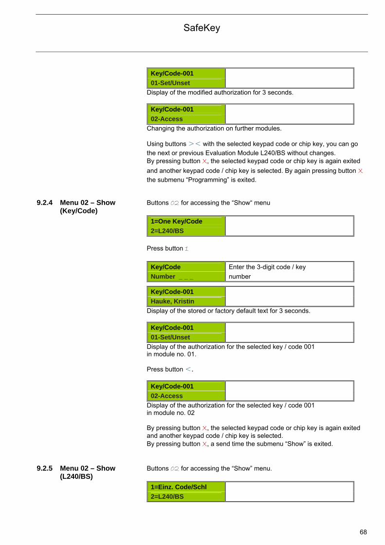
SafeKey
68
Key/Code-001
01-Set/Unset
Display of the modified authorization for 3 seconds.
Key/Code-001
02-Access
Changing the authorization on further modules. Using buttons >< with the selected keypad code or chip key, you can go
the next or previous Evaluation Module L240/BS without changes. By pressing button X, the selected keypad code or chip key is again exited
and another keypad code / chip key is selected. By again pressing button X
the submenu “Programming” is exited. 9.2.4 Menu 02 – Show
(Key/Code) Buttons 02 for accessing the “Show“ menu
1=One Key/Code
2=L240/BS
Press button 1
Key/Code Enter the 3-digit code / key Number _ _ _ number
Key/Code-001
Hauke, Kristin
Display of the stored or factory default text for 3 seconds.
Key/Code-001
01-Set/Unset
Display of the authorization for the selected key / code 001 in module no. 01. Press button <.
Key/Code-001
02-Access
Display of the authorization for the selected key / code 001 in module no. 02 By pressing button X, the selected keypad code or chip key is again exited and another keypad code / chip key is selected. By pressing button X, a send time the submenu “Show” is exited.
9.2.5 Menu 02 – Show
(L240/BS) Buttons 02 for accessing the “Show” menu.
1=Einz. Code/Schl
2=L240/BS

SafeKey
69
Press button 2.
L240/BS
Number _
Enter the address of the Evaluation Module.
Key/Code-001
Hauke, Kristin
Display of the stored or factory default text for 3 seconds.
Key/Code-001
Set/Unset
Display of the authorization for the key / code 001 in the selected module. Press button <.
Key/Code-002
Access
Display of the authorization for the key / code 002 in the selected module. By pressing button X, the selected Evaluation Module can be exited and another Evaluation Module selected. By pressing button X, a second time the submenu “Show” is exited.
9.2.6 Menu 04 – Delete Buttons 04 for accessing the “Delete” menu.
Key/Code
Number _ _ _
Enter the 3-digit code / key number.
Hauke, Kristin
4 = Confirm
Display of the stored or factory default text. The selected code / key is deleted by pressing the ! button.
Delete
OK
The selected code / key has been deleted from all evaluation modules.
Key/Code
Number _ _ _
Further codes / keys can be deleted. By pressing button X, the submenu “Delete” is exited.
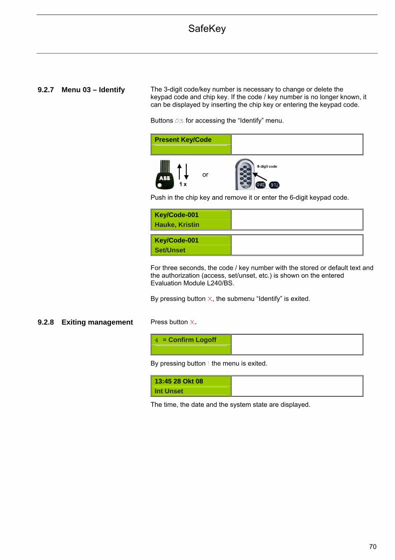
SafeKey
70
9.2.7 Menu 03 – Identify The 3-digit code/key number is necessary to change or delete the
keypad code and chip key. If the code / key number is no longer known, it can be displayed by inserting the chip key or entering the keypad code. Buttons 03 for accessing the “Identify” menu.
Present Key/Code
or Push in the chip key and remove it or enter the 6-digit keypad code.
Key/Code-001
Hauke, Kristin
Key/Code-001
Set/Unset
For three seconds, the code / key number with the stored or default text and the authorization (access, set/unset, etc.) is shown on the entered Evaluation Module L240/BS. By pressing button X, the submenu “Identify” is exited.
9.2.8 Exiting management Press button X.
4 = Confirm Logoff
By pressing button ! the menu is exited.
13:45 28 Okt 08
Int Unset
The time, the date and the system state are displayed.
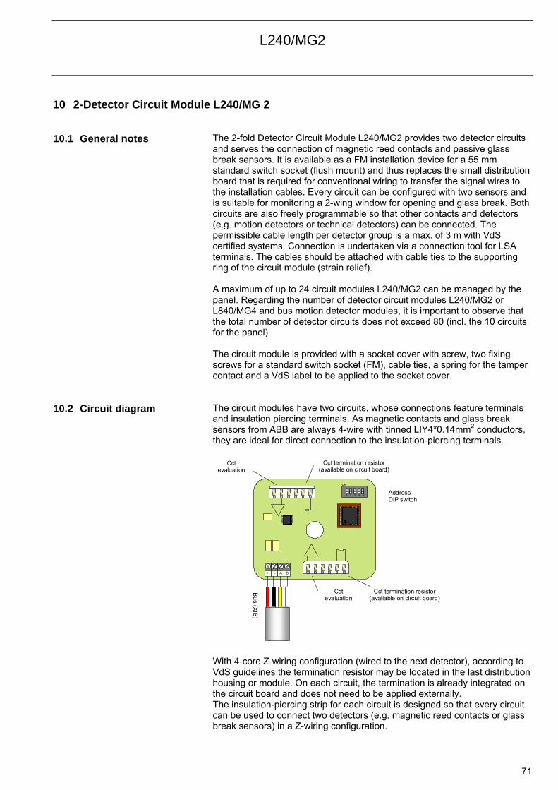
L240/MG2
71
10 2-Detector Circuit Module L240/MG 2 10.1 General notes The 2-fold Detector Circuit Module L240/MG2 provides two detector circuits
and serves the connection of magnetic reed contacts and passive glass break sensors. It is available as a FM installation device for a 55 mm standard switch socket (flush mount) and thus replaces the small distribution board that is required for conventional wiring to transfer the signal wires to the installation cables. Every circuit can be configured with two sensors and is suitable for monitoring a 2-wing window for opening and glass break. Both circuits are also freely programmable so that other contacts and detectors (e.g. motion detectors or technical detectors) can be connected. The permissible cable length per detector group is a max. of 3 m with VdS certified systems. Connection is undertaken via a connection tool for LSA terminals. The cables should be attached with cable ties to the supporting ring of the circuit module (strain relief). A maximum of up to 24 circuit modules L240/MG2 can be managed by the panel. Regarding the number of detector circuit modules L240/MG2 or L840/MG4 and bus motion detector modules, it is important to observe that the total number of detector circuits does not exceed 80 (incl. the 10 circuits for the panel). The circuit module is provided with a socket cover with screw, two fixing screws for a standard switch socket (FM), cable ties, a spring for the tamper contact and a VdS label to be applied to the socket cover.
10.2 Circuit diagram The circuit modules have two circuits, whose connections feature terminals
and insulation piercing terminals. As magnetic contacts and glass break sensors from ABB are always 4-wire with tinned LIY4*0.14mm2 conductors, they are ideal for direct connection to the insulation-piercing terminals.
Bu
s (XIB
)
Address DIP switch
1 2 3 4 5
ON
+ - A B
Cct evaluation
Cct termination resistor (available on circuit board)
Cct evaluation
Cct termination resistor (available on circuit board)
With 4-core Z-wiring configuration (wired to the next detector), according to VdS guidelines the termination resistor may be located in the last distribution housing or module. On each circuit, the termination is already integrated on the circuit board and does not need to be applied externally. The insulation-piercing strip for each circuit is designed so that every circuit can be used to connect two detectors (e.g. magnetic reed contacts or glass break sensors) in a Z-wiring configuration.
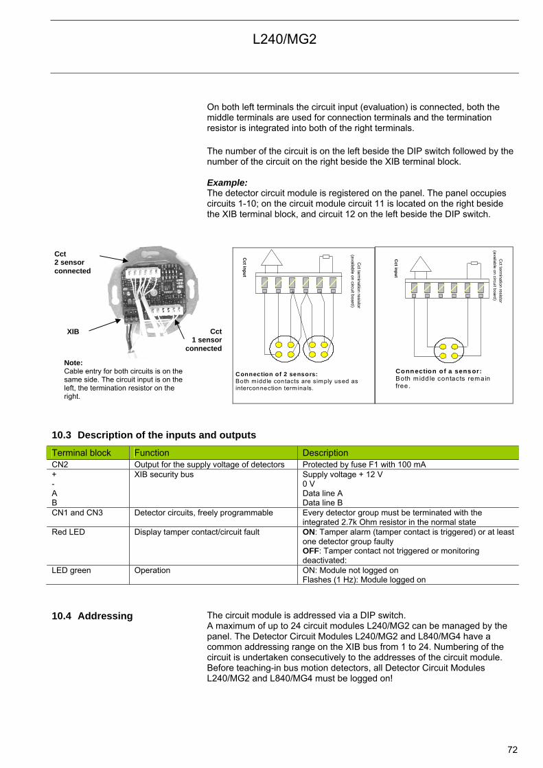
L240/MG2
72
On both left terminals the circuit input (evaluation) is connected, both the middle terminals are used for connection terminals and the termination resistor is integrated into both of the right terminals. The number of the circuit is on the left beside the DIP switch followed by the number of the circuit on the right beside the XIB terminal block. Example: The detector circuit module is registered on the panel. The panel occupies circuits 1-10; on the circuit module circuit 11 is located on the right beside the XIB terminal block, and circuit 12 on the left beside the DIP switch.
Connection of 2 sensors: Both midd le contacts are simply used as interconnection termina ls.
Cct te
rmina
tion re
sistor
(availa
ble o
n circuit board
)
Cct in
pu
t
Connection o f a sens or: Both m idd le contacts remain free.
Cct term
ination resistor (available
on circuit board)
Cct in
pu
t
10.3 Description of the inputs and outputs
Terminal block Function Description CN2 Output for the supply voltage of detectors Protected by fuse F1 with 100 mA + - A B
XIB security bus Supply voltage + 12 V 0 V Data line A Data line B
CN1 and CN3 Detector circuits, freely programmable Every detector group must be terminated with the integrated 2.7k Ohm resistor in the normal state
Red LED Display tamper contact/circuit fault ON: Tamper alarm (tamper contact is triggered) or at least one detector group faulty OFF: Tamper contact not triggered or monitoring deactivated:
LED green Operation ON: Module not logged on Flashes (1 Hz): Module logged on
10.4 Addressing The circuit module is addressed via a DIP switch.
A maximum of up to 24 circuit modules L240/MG2 can be managed by the panel. The Detector Circuit Modules L240/MG2 and L840/MG4 have a common addressing range on the XIB bus from 1 to 24. Numbering of the circuit is undertaken consecutively to the addresses of the circuit module. Before teaching-in bus motion detectors, all Detector Circuit Modules L240/MG2 and L840/MG4 must be logged on!
Note: Cable entry for both circuits is on the same side. The circuit input is on the left, the termination resistor on the right.
Cct 2 sensor connected
Cct 1 sensor
connected
XIB
L240/MG2
73
Example: Two Detector Circuit Modules L240/MG2, one Detector Circuit Module L840/MG4 and three bus detector modules are operated on an Intrusion Alarm Panel L240. • First of all the three circuit modules must be registered. • The panel occupies circuits 1-10. • The first Detector Circuit Module L240/MG2 has an XIB address 01 and
the circuits 11 to 12. • The second Detector Circuit Module L840/MG4 has an XIB address 02
and the circuits 13 to 16. • The third Detector Circuit Module L240/MG2 has an XIB address 03 and
the circuits 17 to 18. • Then the three bus detector modules must be teached-in (circuits 19-21).
10.5 Commissioning The monitoring of the panel tamper contact can be deactivated after logon of
the circuit module. After commissioning, the monitoring must be reactivated. The installation and connection is undertaken on the panel with the power switched off.
• The individual connection cables and detectors correspond with the connection schematic. Connection is undertaken via a connection tool for LSA terminals.
• Every circuit must be terminated with the integrated termination resistor of 2.7 kΩ.
• Set the XIB address on the DIP switch (see chapter 10.6 Address table). • Apply the voltage to the panel , the red and green LEDs light up.
Logon/Logoff • Select the function “01=System Size” in the engineer Edit menu.
01=System Size
02=Area Opts
• The corresponding number (2-digit) should be entered for the circuit
modules.
System Size
Concs-xx
• Exit the Hardware menu with button X and assign the circuit module to
the areas (see Area assignment). As standard all circuit modules are assigned to area 1.
• As monitoring of the tamper contact is active a tamper alarm is triggered (red LED lights up).
• Test the individual circuits. Note: After logging off a circuit module, the freed circuits are replaced by the following circuit, i.e. all the following circuits are moved upwards. For this reason all circuits (properties, type, area and text) must be inspected from the logged off circuit module and must be checked and corrected if necessary.
L240/MG2
74
After teach-in the Detector Circuit Module L240/MG2 has two circuits each with the following properties: (also refer to Properties of the circuit types chapter 8.1.3.2 on page 56).
• Standard or EIB/KNX • Intrusion circuit (Cct) • Cct off int off • Cct off ext. off • Silent alarm off • Print unset off
The circuits are thus active with internal and external setting. After pressing button 5 “? Cct Fault” on the keypad the faults of the individual circuit are displayed (e.g. Cct14 or the stored text for the detector). The circuit groups can also be reprogrammed to other circuit types (e.g. personal attack or technology circuits). Area assignment • On the programming level (Engineer menu) select function “07=Concs”.
Concentrator
Number _
• Enter the address of the circuit.
Concentrator-0x
Area-1
• Enter the circuit area and exit the Hardware menu with button X.
Monitoring tamper contact yes/no • Select the function “13=2-Conc Tamper“ in the programming level.
13=2-Conc Tamper
15=Defaults
After the supply voltage is applied, monitoring of all tamper contacts is reactivated.
• Successively for all logged on Detector Circuit Modules L240/MG2, the monitoring of the panel tamper can be activated (ON) or deactivated (OFF).
•
2-Conc Tamper
2-Conc. xx-On
The panel tamper is activated on Detector Circuit Module L240/MG2 with the XIB address 03.
After commissioning: • Apply the spring and the pin for the panel tamper contact. • Activate monitoring of the panel tamper contact. • Screw on the module onto the supporting ring with the enclosed fixing
screws on the FM switch socket. • The cover of the socket should be screwed on with the enclosed cover
screw. • Perform a function test of the tamper cover contact by opening the socket
cover (tamper alarm on the Intrusion Alarm Panel). The screw for opening the socket cover should be sealed with the enclosed VdS label.
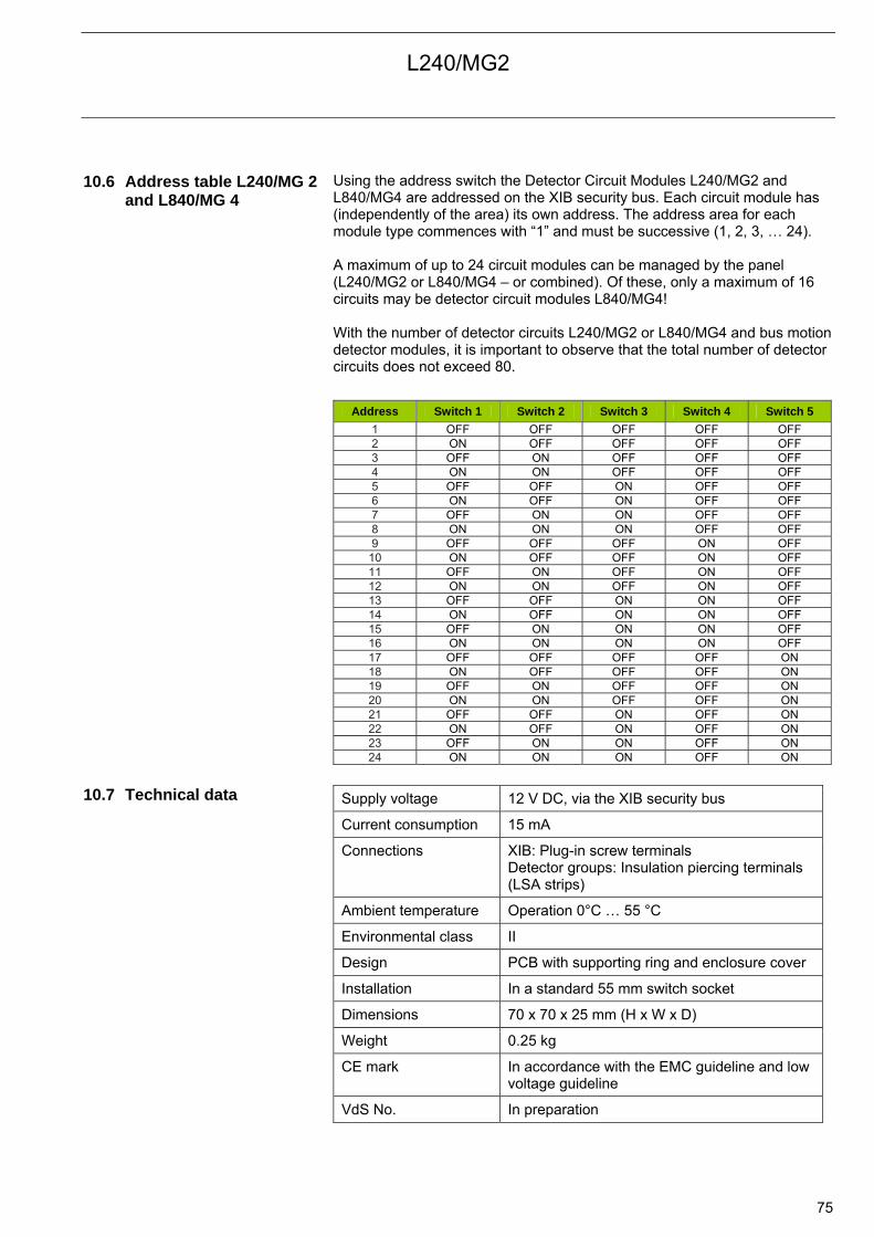
L240/MG2
75
10.6 Address table L240/MG 2 and L840/MG 4
Using the address switch the Detector Circuit Modules L240/MG2 and L840/MG4 are addressed on the XIB security bus. Each circuit module has (independently of the area) its own address. The address area for each module type commences with “1” and must be successive (1, 2, 3, … 24). A maximum of up to 24 circuit modules can be managed by the panel (L240/MG2 or L840/MG4 – or combined). Of these, only a maximum of 16 circuits may be detector circuit modules L840/MG4! With the number of detector circuits L240/MG2 or L840/MG4 and bus motion detector modules, it is important to observe that the total number of detector circuits does not exceed 80.
Address Switch 1 Switch 2 Switch 3 Switch 4 Switch 5 1 OFF OFF OFF OFF OFF 2 ON OFF OFF OFF OFF 3 OFF ON OFF OFF OFF 4 ON ON OFF OFF OFF 5 OFF OFF ON OFF OFF 6 ON OFF ON OFF OFF 7 OFF ON ON OFF OFF 8 ON ON ON OFF OFF 9 OFF OFF OFF ON OFF
10 ON OFF OFF ON OFF 11 OFF ON OFF ON OFF 12 ON ON OFF ON OFF 13 OFF OFF ON ON OFF 14 ON OFF ON ON OFF 15 OFF ON ON ON OFF 16 ON ON ON ON OFF 17 OFF OFF OFF OFF ON 18 ON OFF OFF OFF ON 19 OFF ON OFF OFF ON 20 ON ON OFF OFF ON 21 OFF OFF ON OFF ON 22 ON OFF ON OFF ON 23 OFF ON ON OFF ON 24 ON ON ON OFF ON
10.7 Technical data Supply voltage 12 V DC, via the XIB security bus
Current consumption 15 mA
Connections XIB: Plug-in screw terminals Detector groups: Insulation piercing terminals (LSA strips)
Ambient temperature Operation 0°C … 55 °C
Environmental class II
Design PCB with supporting ring and enclosure cover
Installation In a standard 55 mm switch socket
Dimensions 70 x 70 x 25 mm (H x W x D)
Weight 0.25 kg
CE mark In accordance with the EMC guideline and low voltage guideline
VdS No. In preparation
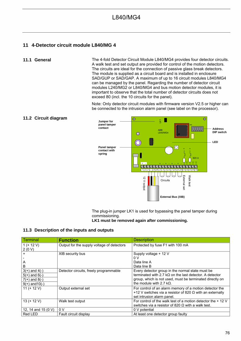
L840/MG4
76
11 4-Detector circuit module L840/MG 4 11.1 General The 4-fold Detector Circuit Module L840/MG4 provides four detector circuits.
A walk test and set output are provided for control of the motion detectors. The circuits are ideal for the connection of passive glass break detectors. The module is supplied as a circuit board and is installed in enclosure SAD/GUP or SAD/GAP. A maximum of up to 16 circuit modules L840/MG4 can be managed by the panel. Regarding the number of detector circuit modules L240/MG2 or L840/MG4 and bus motion detector modules, it is important to observe that the total number of detector circuits does not exceed 80 (incl. the 10 circuits for the panel).
Note: Only detector circuit modules with firmware version V2.5 or higher can be connected to the intrusion alarm panel (see label on the processor).
11.2 Circuit diagram
LED
ABB L840/MG4
Panel tamper contact with spring
Address DIP switch
External Bus (XIB)
+ -
12V
output
Extern
al set
Walk te
st
1 2 3 4 5
ON
LK1
1 2 + - A B 3 4 5 6 7 8 9 10 11 12 13 14 15
+ +
+ - + - + - + -
820
Jumper for panel tamper contact
Circuits
The plug-in jumper LK1 is used for bypassing the panel tamper during commissioning. LK1 must be removed again after commissioning.
11.3 Description of the inputs and outputs Terminal Function Description 1 (+ 12 V) 2 (0 V)
Output for the supply voltage of detectors Protected by fuse F1 with 100 mA
+ - A B
XIB security bus Supply voltage + 12 V 0 V Data line A Data line B
3(+) and 4(-) 5(+) and 6(-) 7(+) and 8(-) 9(+) and10(-)
Detector circuits, freely programmable Every detector group in the normal state must be terminated with 2.7 kΩ on the last detector. A detector group, which is not used, must be terminated directly on the module with 2.7 kΩ.
11 (+ 12 V) Output external set For control of an alarm memory of a motion detector the +12 V switches via a resistor of 820 Ω with an externally set intrusion alarm panel.
13 (+ 12 V) Walk test output For control of the walk test of a motion detector the + 12 V switches via a resistor of 820 Ω with a walk test.
12, 14 and 15 (0 V) 0 V 0 V potential Red LED Fault circuit display At least one detector group faulty

L840/MG4
77
11.4 DIP switch/jumper
settings: The following settings can be defined with the DIP switch:
Switch 1-5: Address on the XIB security bus (see addressing)
The panel tamper contact can be bypassed with jumper LK1: Jumper LK1: Plugged-in: Panel tamper not functional Open: Panel tamper functional
11.5 Addressing The circuit module is addressed via a DIP switch. A maximum of up to 16
circuit modules L840/MG4 can be managed by the panel. Detector circuit module L240/MG 2 and L840/MG4 have a common addressing area on the XIB bus from 1 to 24. Numbering of the circuits is undertaken consecutively to the addresses of the circuit module (see chapter 10.6 Address table). Before teaching-in bus motion detectors, all Detector Circuit Modules L240/MG2 and L840/MG4 must already be logged on! Example: Two Detector Circuit Modules L840/MG4, one Detector Circuit Module L240/MG2 and three bus detector modules are operated on an Intrusion Alarm Panel L240. First of all the three circuit modules must be registered. The panel occupies circuits 1-10. The first Detector Circuit Module L840/MG4 has an XIB address 01 and
the circuits 11 to 14. The second Detector Circuit Module L240/MG2 has an XIB address 02
and the circuits 15 to 16. The third Detector Circuit Module L840/MG4 has an XIB address 03 and
the circuits 17 to 20. Then the three bus detector modules must be teached-in
(circuits 21-23).
11.6 Commissioning The plug-in jumper LK1 can be used for bypassing the panel tamper to
suppress the tampering alarm during commissioning (otherwise tamper alarm). Jumper LK1 must be removed again after commissioning. The installation and connection is undertaken on the panel with the power switched off.
Screw on the circuit module to the distribution surface in the SAD enclosure; connect the individual connection cables and detectors in accordance with the circuit diagram. Terminate every circuit with a termination resistor of 2.7 kΩ on the last detector.
Set the address on the DIP switch (see chapter 10.6 Address table) Apply the panel supply.
Logon/Logoff On the programming level (Engineer menu) select function
“01=Hardware”.
01=System Size
02=Area Opts
The corresponding number (2-digit) should be entered for the circuit
modules.
System Size
Concs-xx

L840/MG4
78
Exit the Hardware menu with button X and assign the circuit module to the areas. As standard all circuit modules are assigned to area 1.
Test the individual circuits.
Note: After logging off a circuit module, the freed circuits are replaced by the following circuit, i.e. all the following circuits are moved upwards. For this reason all circuits (properties, type, area and text) must be inspected from the logged off circuit module and must be checked and corrected if necessary. After teach-in the Detector Circuit Module L840/MG4 has four circuits each with the following properties: (also refer to Properties of the circuit types chapter 8.1.3.2 on page 56) Standard or EIB/KNX Intrusion circuit (Cct) Cct off int off Cct off ext. off Silent alarm off Print unset off The circuits are thus active with internal and external setting. After pressing button 5 “? Cct Fault” on the keypad, the faults of the individual circuit are displayed (e.g. Cct14 or the stored text for the detector). The circuits can also be reprogrammed to other circuit types (e.g. personal attack or technology circuits). Area assignment On the programming level (Engineer menu) select function “07=Concs”.
Concentrator
Number _
Enter the address of the circuit.
Concentrator-0x
Area-1
Enter the circuit area and exit the Hardware menu with button X. Remove jumper LK1 after commissioning, insert the spring for the panel tamper contact and close the enclosure cover.
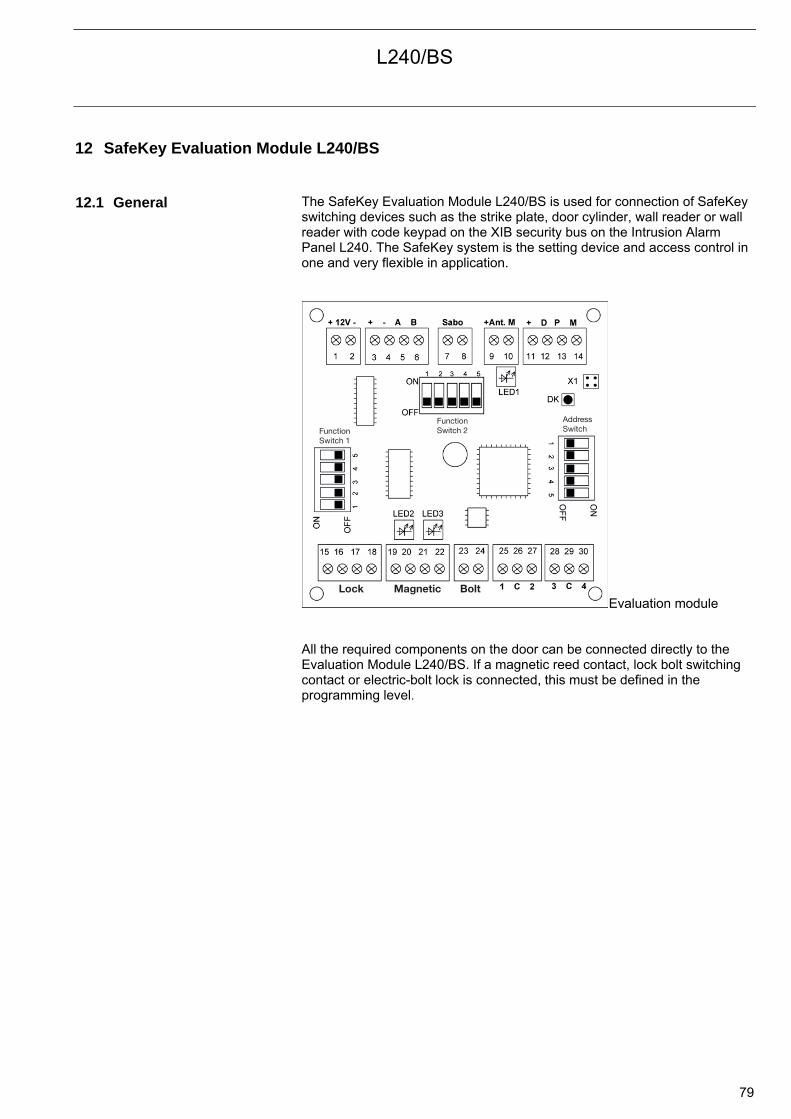
L240/BS
79
12 SafeKey Evaluation Module L240/BS 12.1 General
The SafeKey Evaluation Module L240/BS is used for connection of SafeKey switching devices such as the strike plate, door cylinder, wall reader or wall reader with code keypad on the XIB security bus on the Intrusion Alarm Panel L240. The SafeKey system is the setting device and access control in one and very flexible in application.
Lock Magnetic Bolt
FunctionSwitch 1
FunctionSwitch 2
AddressSwitch
Evaluation module All the required components on the door can be connected directly to the Evaluation Module L240/BS. If a magnetic reed contact, lock bolt switching contact or electric-bolt lock is connected, this must be defined in the programming level.
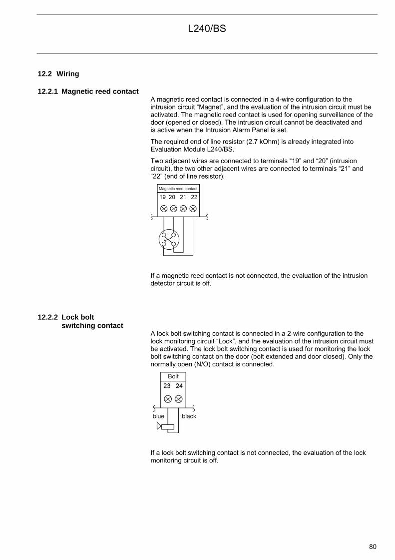
L240/BS
80
12.2 Wiring 12.2.1 Magnetic reed contact
A magnetic reed contact is connected in a 4-wire configuration to the intrusion circuit “Magnet”, and the evaluation of the intrusion circuit must be activated. The magnetic reed contact is used for opening surveillance of the door (opened or closed). The intrusion circuit cannot be deactivated and is active when the Intrusion Alarm Panel is set.
The required end of line resistor (2.7 kOhm) is already integrated into Evaluation Module L240/BS.
Two adjacent wires are connected to terminals “19” and “20” (intrusion circuit), the two other adjacent wires are connected to terminals “21” and “22” (end of line resistor).
Magnetic reed contact
If a magnetic reed contact is not connected, the evaluation of the intrusion detector circuit is off.
12.2.2 Lock bolt switching contact
A lock bolt switching contact is connected in a 2-wire configuration to the lock monitoring circuit “Lock”, and the evaluation of the intrusion circuit must be activated. The lock bolt switching contact is used for monitoring the lock bolt switching contact on the door (bolt extended and door closed). Only the normally open (N/O) contact is connected.
Bolt
blue black
If a lock bolt switching contact is not connected, the evaluation of the lock monitoring circuit is off.
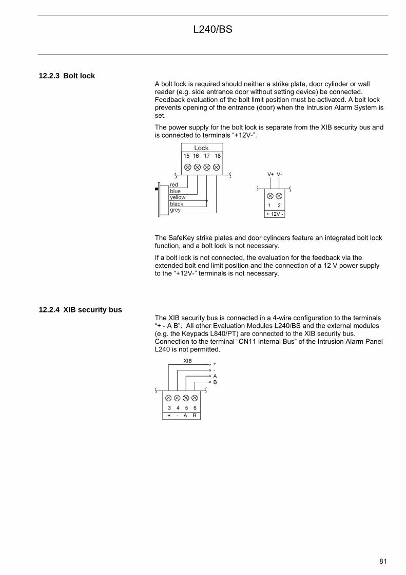
L240/BS
81
12.2.3 Bolt lock A bolt lock is required should neither a strike plate, door cylinder or wall reader (e.g. side entrance door without setting device) be connected. Feedback evaluation of the bolt limit position must be activated. A bolt lock prevents opening of the entrance (door) when the Intrusion Alarm System is set.
The power supply for the bolt lock is separate from the XIB security bus and is connected to terminals “+12V-”.
Lock
bluered
yellowblackgrey
The SafeKey strike plates and door cylinders feature an integrated bolt lock function, and a bolt lock is not necessary.
If a bolt lock is not connected, the evaluation for the feedback via the extended bolt end limit position and the connection of a 12 V power supply to the “+12V-” terminals is not necessary.
12.2.4 XIB security bus The XIB security bus is connected in a 4-wire configuration to the terminals “+ - A B”. All other Evaluation Modules L240/BS and the external modules (e.g. the Keypads L840/PT) are connected to the XIB security bus. Connection to the terminal “CN11 Internal Bus” of the Intrusion Alarm Panel L240 is not permitted.
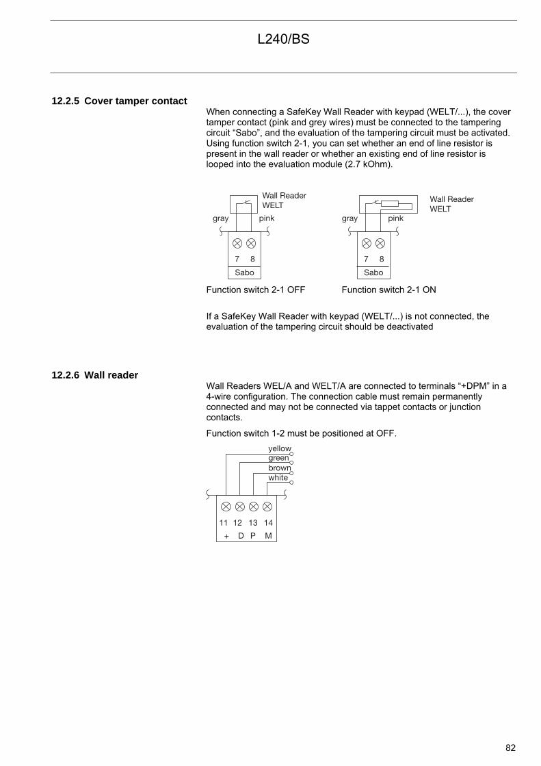
L240/BS
82
12.2.5 Cover tamper contact When connecting a SafeKey Wall Reader with keypad (WELT/...), the cover tamper contact (pink and grey wires) must be connected to the tampering circuit “Sabo”, and the evaluation of the tampering circuit must be activated. Using function switch 2-1, you can set whether an end of line resistor is present in the wall reader or whether an existing end of line resistor is looped into the evaluation module (2.7 kOhm).
7 8
Sabo
Wall ReaderWELT
pinkgray
7 8
Sabo
Wall ReaderWELT
pinkgray
Function switch 2-1 OFF Function switch 2-1 ON
If a SafeKey Wall Reader with keypad (WELT/...) is not connected, the evaluation of the tampering circuit should be deactivated
12.2.6 Wall reader Wall Readers WEL/A and WELT/A are connected to terminals “+DPM” in a 4-wire configuration. The connection cable must remain permanently connected and may not be connected via tappet contacts or junction contacts.
Function switch 1-2 must be positioned at OFF.
11 12 13 14
+ D P M
greenyellow
brownwhite
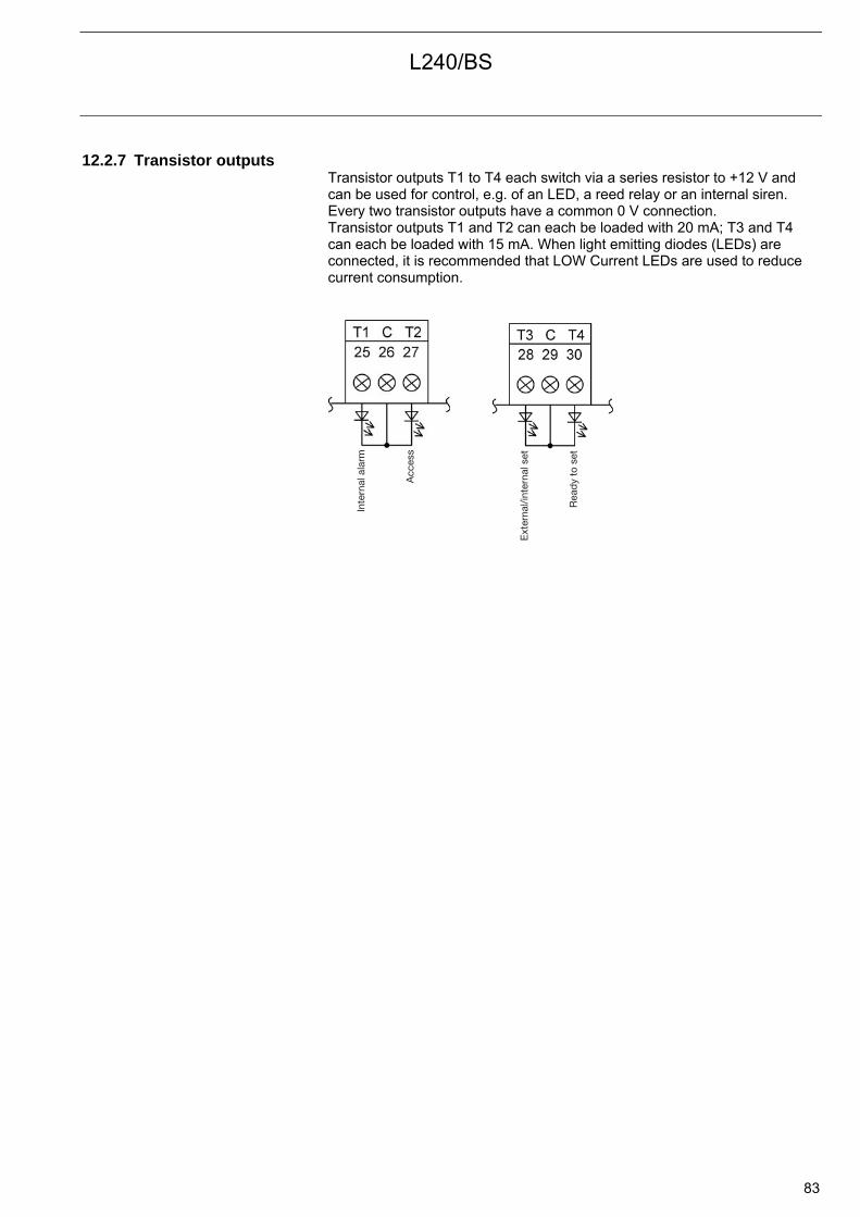
L240/BS
83
12.2.7 Transistor outputs Transistor outputs T1 to T4 each switch via a series resistor to +12 V and can be used for control, e.g. of an LED, a reed relay or an internal siren. Every two transistor outputs have a common 0 V connection. Transistor outputs T1 and T2 can each be loaded with 20 mA; T3 and T4 can each be loaded with 15 mA. When light emitting diodes (LEDs) are connected, it is recommended that LOW Current LEDs are used to reduce current consumption.
Inte
rnal
ala
rm
Acc
ess
Ext
erna
l/int
erna
l set
Rea
dy
to s
et

L240/BS
84
12.3 Description of the inputs and outputs Terminal Description Function Connection wire 01 +12 V 02 - (0V)
Connection for the separate power supply of the bolt lock from the XIB security bus, e.g. on an Intrusion Alarm Panel L240 to “V+/V-”. The power supply and the XIB security bus must be supplied from the same Intrusion Alarm Panel (common reference voltage).
03 + (+12 V) 04 - (0 V) 05 A (data line) 06 B (data line)
Connection for external XIB security bus
07 Sabo (Cct) Grey wire 08
Connection for the cover tamper contact of a SafeKey Wall reader with keypad Pink wire
09 +ANT 10 M
Not used
11 + Yellow wire 12 D Green wire 13 P Brown wire 14 M
Wired connection for a SafeKey Wall Reader
White wire 15 Lock (+12 V) Red wire 16 (0 V) Blue wire 17 (Control) Yellow and black
wire 18 (feedback)
Connection for a bolt lock (required with SafeKey Wall Reader)
Grey wire 19 20
Magnet (Intrusion cct)
Two adjacent wires
21 22
(End of line resistor (2.7 kOhm)
Magnetic reed contact connection for monitoring of door opening
Two other adjacent wires
23 Blue wire 24
Lock (Lock cct) Lock bolt switching contact connection for monitoring of the door lock Black wire
25 Transistor output T1 Internal alarm: Switches +12 V via a 470 Ohm series resistor on an internal alarm (Imax=20 mA)
26 C 0 V (common for terminal 25 and 27) 27 Transistor output T2 Access: Switches +12 V for six seconds via a 470
Ohm series resistor should a valid key code/chipkey be used (Imax=20 mA)
28 Transistor output T3 External/internal set: Switches +12 V via an 820 Ohm series resistor if the Intrusion Alarm Panel is internally or externally set (Imax=15 mA)
29 C 0 V (common for terminal 28 and 30) 30 Transistor output T4 Ready to set: Switches +12 V via an 820 Ohm
series resistor if the Intrusion Alarm Panel is externally set (Imax=15 mA)

L240/BS
85
12.4 LEDs The LEDs on Evaluation Module L240/BS have the following functions:
12.4.1 Light emitting diode “LED1” (red)
“LED1” is without function.
12.4.2 Light emitting diode “LED2” (green)
Green “LED2” indicates communication between Evaluation Module L240/BS and a connected wall reader, strike plate or door cylinder (lights up for about 6 seconds), when a chipkey is inserted or a keypad code is entered.
LED off: Normal operation LED on: Entry of a keypad code/ insertion of a chip key
12.4.3 Light emitting diode “LED3” (red)
LED3 is without function.
12.5 DIP switch blocks Various settings can be predefined using the three DIP switch blocks “Function switch 1”, “Function switch 2” and “Address switch 3”. Further settings are undertaken in the programming level using Keypad L240/PT.
Switch position in “OFF” “ON”
L240/BS
86
12.5.1 Function switch 1 The following settings and parameters can be undertaken with function switch 1:
Function switch 1-1 “Connection of 0 V potential bolt lock-XIB”:
Function switch 1-1 can establish potential equalization between the minus of the bolt lock voltage supply (terminal 16) and the minus of the XIB security bus (terminal 4).
As there is a separate voltage supply for the lock bolt and the XIB bus, differing cable lengths and current loading can result in potential shifts.
Note: The power supply for the bolt lock must be provided from the same Intrusion Alarm Panel as the XIB bus.
OFF: No connection between the 0 V potential from the bolt lock and the XIB bus (standard)
ON: A connection and thus the same potential between the 0 V potential from the bolt lock and XIB bus
Function switch 1-2: Must be “OFF”.
Function switch 1-3 “free”:
Function switch 1-3 has no function and must be set to OFF.
Function switch 1-4 “Send High/Low”:
Must be “OFF”.
Function switch 1-5 “Test wireless communication”:
Must be “OFF”.
12.5.2 Function switch 2 The following settings and parameters can be undertaken with function switch 2:
Functions switch 2-1 “Sabo resistor” Using function switch 2-1, the end of line resistor (2.7 kOhm) for the tampering circuit (terminals 7-8) in the evaluation module can be bypassed.
OFF: The end of line resistor in the evaluation module is looped in. Only the cover tamper contact (N/O contact) in the SafeKey Wall Reader and no end of line resistor is required (standard).
ON: The end of line resistor in the evaluation module is bypassed. Only the cover tamper contact (N/O contact) in the SafeKey Wall Reader and an end of line resistor (2.7 kOhm) are required.
Function switch 2-2 “free”:
Function switch 2-2 has no function and must be set to OFF.
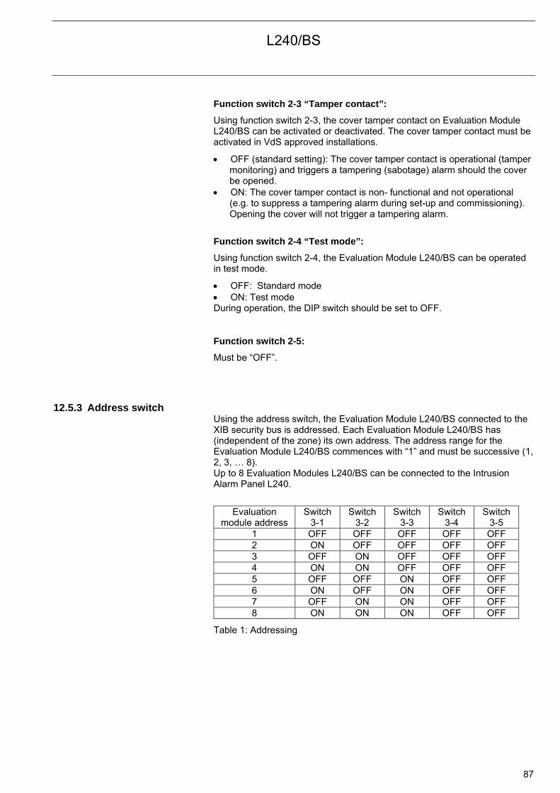
L240/BS
87
Function switch 2-3 “Tamper contact”:
Using function switch 2-3, the cover tamper contact on Evaluation Module L240/BS can be activated or deactivated. The cover tamper contact must be activated in VdS approved installations.
OFF (standard setting): The cover tamper contact is operational (tamper monitoring) and triggers a tampering (sabotage) alarm should the cover be opened.
ON: The cover tamper contact is non- functional and not operational (e.g. to suppress a tampering alarm during set-up and commissioning). Opening the cover will not trigger a tampering alarm.
Function switch 2-4 “Test mode”:
Using function switch 2-4, the Evaluation Module L240/BS can be operated in test mode.
OFF: Standard mode ON: Test mode During operation, the DIP switch should be set to OFF.
Function switch 2-5:
Must be “OFF”.
12.5.3 Address switch Using the address switch, the Evaluation Module L240/BS connected to the XIB security bus is addressed. Each Evaluation Module L240/BS has (independent of the zone) its own address. The address range for the Evaluation Module L240/BS commences with “1” and must be successive (1, 2, 3, … 8). Up to 8 Evaluation Modules L240/BS can be connected to the Intrusion Alarm Panel L240.
Evaluation module address
Switch 3-1
Switch 3-2
Switch 3-3
Switch 3-4
Switch 3-5
1 OFF OFF OFF OFF OFF 2 ON OFF OFF OFF OFF 3 OFF ON OFF OFF OFF 4 ON ON OFF OFF OFF 5 OFF OFF ON OFF OFF 6 ON OFF ON OFF OFF 7 OFF ON ON OFF OFF 8 ON ON ON OFF OFF
Table 1: Addressing

L240/BS
88
12.6 Commissioning The following procedure must be observed when putting the Intrusion Alarm Panel L240 and the Evaluation Module L240/BS into operation. The commissioning instructions in the product manual of the Intrusion Alarm Panel, strike plate and door cylinder must be observed.
Important: During all installation and commissioning work, such as
Modifications on the DIP switch settings Connection or disconnection of the Evaluation Module L240/BS with the
XIB security bus, the Intrusion Alarm Panel must be powered off (mains and battery supply disconnected). The installation and commissioning may only be carried out by electrical specialists!
Should evaluation modules be logged off in the programming level (Menu “Hardware”), they should be subsequently disconnected from the XIB security bus.
1. Intrusion Alarm Panel L240 commissioning:
The power supply to the Intrusion Alarm Panel must be switched off, and no sensors or detectors should be initially connected, rather
The zones (inputs 1 to 6 and 8 to 10) with the 2.7 kOhm end of line resistor must be connected directly to the terminals
The lock detector circuit (input 7) must be bypassed without a resistor The outputs for both sirens and strobe lights are to be fitted with the 1
kOhm end of line resistor directly on the terminals The tamper input for the cover tamper contact, the input Comm fault and
Comm alarm must be connected with a jumper to 0V At least one LCD Keypad L240/PT with address 1 must be connected to the external bus (XIB). A total of maximum 8 keypads can be connected. Using this keypad, it is possible to program and manage the chipkey and keypad code in addition to operating the Intrusion Alarm Panel.
No detector circuit for setting the Intrusion Alarm Panels may be used (e.g. circuit 10 of the L240). This detector circuit only needs to be terminated with a resistor (2.7 kOhm) or can be reprogrammed , e.g. as an intrusion detector group.
2. Mounting the door cylinder/strike plate/wall reader:
The wall reader should be mounted. Refer to the corresponding product manual or technical data sheet for this purpose.
Should there be a communication fault (e.g. during set-up or commissioning) between an Evaluation Module L240/BS and a strike plate or door cylinder, the Intrusion Alarm Panel cannot be set/unset or the door cannot be opened.

L240/BS
89
3. Initial commissioning of Evaluation Module L240/BS:
All Evaluation Modules L240/BS must be connected to an external bus (XIB)
The addressing of the Evaluation Module L240/BS can be found in “Address switch”
Connection of all components to the Evaluation Module L240/BS is undertaken in accordance with instructions in chapter “Wiring”.
Should the tampering circuit not be required, it can be deactivated later. However, in order to avoid a tampering alarm during setup and commissioning, function switch 2-1 must be set to OFF, and a wire jumper must be inserted between terminals 7 and 8.
The panel tamper contact on Evaluation Module L240/BS should be bypassed with the function switch (function switch 2-3 set to ON). After set-up and commissioning, the panel tamper contact must be reactivated (function switch 2-3 set to OFF).
Apply the mains supply and batteries The Intrusion Alarm Panel is now ready to operate and set. On the
“Ready to Set” (terminal 16) transistor output, a voltage of 13.0 V to “V+” can be measured.
A diverse range of functions can be tested (e.g. internal set), and/or programming with an LCD keypad can be undertaken.
Communication between an evaluation module and a wall reader should be tested as follows: - With a wired connection of a wall reader, LED2 on the evaluation module lights up for 6 seconds after insertion of any chipkey or when buttons 0 to 9 are pressed.
The number of Evaluation Modules L240/BS connected to the XIB security bus should be entered in the programming menu “Hardware L240/B/BS”. The Evaluation Modules L240/BS are detected by the intrusion Alarm Panel and operated in accordance with their delivered state.
Important: The Evaluation Modules must now be reset to the delivery state (including deleting the database for management of the chipkeys and keypad codes). This procedure is described in the chapter “Reset”. Keypad codes and chipkeys may only be created after the reset!
Note: After the reset, the number of Evaluation Modules L240/BS connected to the XIB security bus must be re-entered in the programming menu “Hardware L240/B/BS” .
The date and time must be set first to ensure that all information is correctly stored in the event and access log. Synchronization of the newly set date and time occurs in all Evaluation Modules L240/BS within a minute.
The different properties for each Evaluation Module L240/BS must be set in the programming menu “Hardware”. This includes the assignment to a zone, the unsetting method, the evaluation of the intrusion, tampering or lock detector circuit and the feedback from a bolt lock.
For each Evaluation Module L240/BS, an individual “Hardware text” can be stored in the programming menu “Texts”).
The keypad code and chipkey must be created. The management (creation, deleting or editing) and associated rights (e.g. access, set/unset) are described in chapter “Management of the chipkey/keypad code with the LCD Keypad L240/PT”.
The access functions and setting/unsetting must be tested. This procedure is described in the chapter “Operation”.

L240/BS
90
4. After commissioning/set-up
Next the end of line resistors in the Intrusion Alarm Panel can be replaced successively by the actual detector circuits, signalling devices, etc., and correct function should be tested.
After commissioning/set-up, the panel tamper contacts of the evaluation modules must be activated (DIP switch).
The system protocol with the configuration and the measured values should be filled out after commissioning/set-up (may be required for troubleshooting).
5. Adding evaluation modules
Should one or more Evaluation Modules L240/BS be added at a later date, the following must be observed:
The power supply to the Intrusion Alarm Panel should be switched off (mains and battery supply)
The new evaluation modules must be connected to the external bus (XIB), addressed accordingly and all components should be connected to them
Apply the mains supply and batteries The new evaluation modules must be registered in the programming
menu “Hardware L240/B/BS”. The Evaluation Module L240/BS is detected by the intrusion Alarm Panel and operated in accordance with the delivered state.
After the added evaluation module has been registered, the database for management of the keypad codes and chipkeys is not up-to-date and must be copied from an existing evaluation module. This procedure is described in the chapter “Copying”. The database must be copied from an existing evaluation module for each evaluation module that has been added.
The evaluation module is now ready to operate Different properties must be set in the programming menu “Hardware
L240/B/BS” (assignment to a zone, the unsetting method, the evaluation of the intrusion, tampering or lock detector circuit)
For each new Evaluation Module L240/BS, an individual “Hardware text” can be stored in the programming menu.
Further keypad codes ad chipkey may also be added if required.
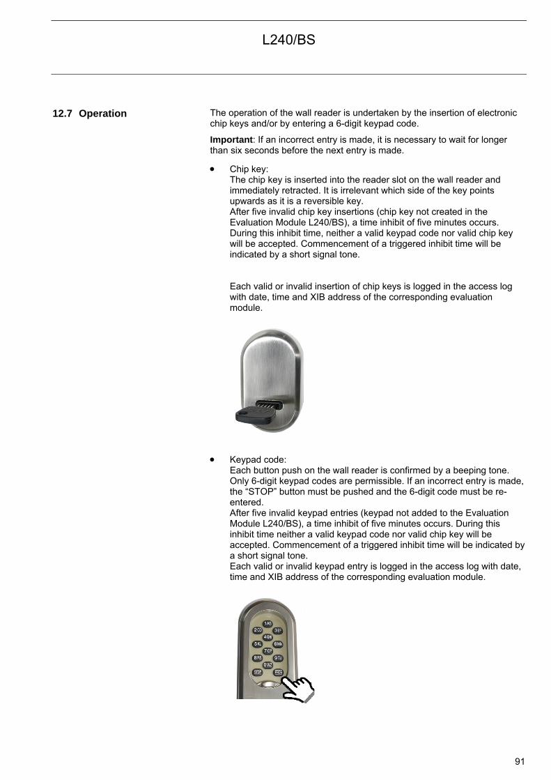
L240/BS
91
12.7 Operation The operation of the wall reader is undertaken by the insertion of electronic
chip keys and/or by entering a 6-digit keypad code.
Important: If an incorrect entry is made, it is necessary to wait for longer than six seconds before the next entry is made.
Chip key: The chip key is inserted into the reader slot on the wall reader and immediately retracted. It is irrelevant which side of the key points upwards as it is a reversible key. After five invalid chip key insertions (chip key not created in the Evaluation Module L240/BS), a time inhibit of five minutes occurs. During this inhibit time, neither a valid keypad code nor valid chip key will be accepted. Commencement of a triggered inhibit time will be indicated by a short signal tone. Each valid or invalid insertion of chip keys is logged in the access log with date, time and XIB address of the corresponding evaluation module.
Keypad code: Each button push on the wall reader is confirmed by a beeping tone. Only 6-digit keypad codes are permissible. If an incorrect entry is made,the “STOP” button must be pushed and the 6-digit code must be re-entered. After five invalid keypad entries (keypad not added to the Evaluation Module L240/BS), a time inhibit of five minutes occurs. During this inhibit time neither a valid keypad code nor valid chip key will be accepted. Commencement of a triggered inhibit time will be indicated by a short signal tone. Each valid or invalid keypad entry is logged in the access log with date, time and XIB address of the corresponding evaluation module.
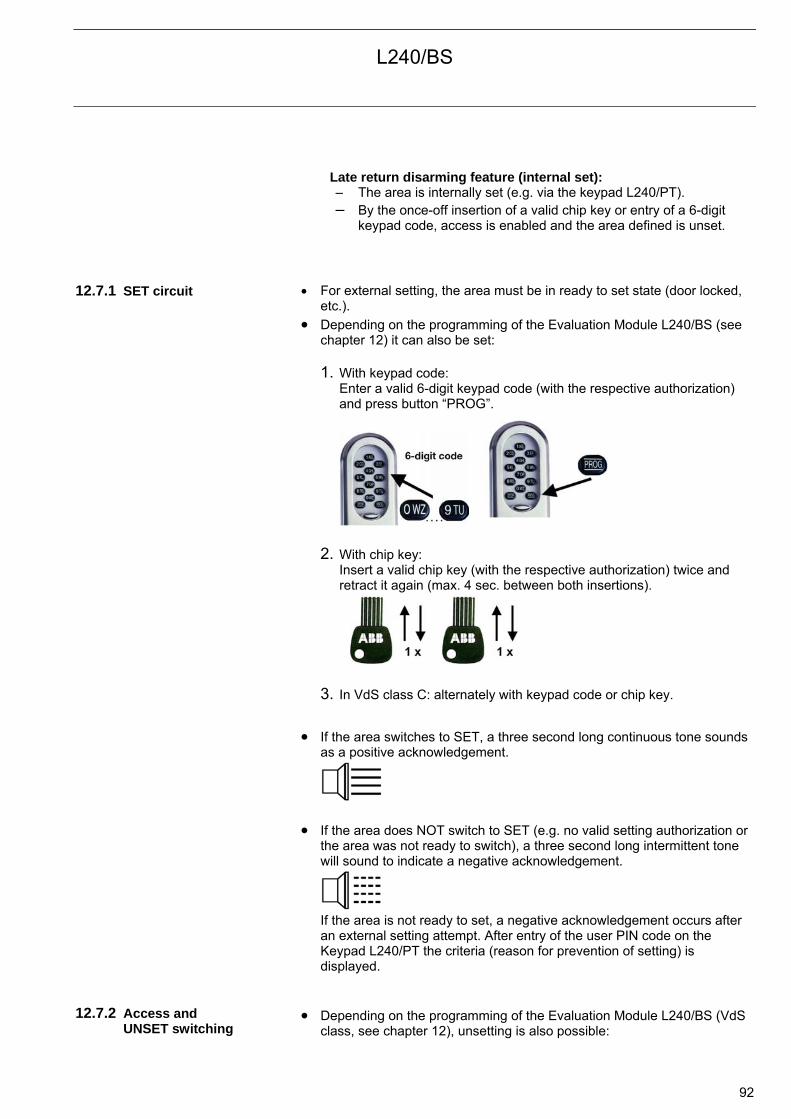
L240/BS
92
Late return disarming feature (internal set): – The area is internally set (e.g. via the keypad L240/PT). – By the once-off insertion of a valid chip key or entry of a 6-digit
keypad code, access is enabled and the area defined is unset. 12.7.1 SET circuit For external setting, the area must be in ready to set state (door locked,
etc.).
Depending on the programming of the Evaluation Module L240/BS (see chapter 12) it can also be set:
1. With keypad code:
Enter a valid 6-digit keypad code (with the respective authorization) and press button “PROG”.
2. With chip key: Insert a valid chip key (with the respective authorization) twice and retract it again (max. 4 sec. between both insertions).
3. In VdS class C: alternately with keypad code or chip key.
If the area switches to SET, a three second long continuous tone sounds as a positive acknowledgement.
If the area does NOT switch to SET (e.g. no valid setting authorization or the area was not ready to switch), a three second long intermittent tone will sound to indicate a negative acknowledgement.
If the area is not ready to set, a negative acknowledgement occurs after an external setting attempt. After entry of the user PIN code on the Keypad L240/PT the criteria (reason for prevention of setting) is displayed.
12.7.2 Access and
UNSET switching Depending on the programming of the Evaluation Module L240/BS (VdS
class, see chapter 12), unsetting is also possible:
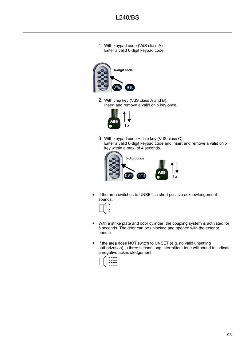
L240/BS
93
1. With keypad code (VdS class A): Enter a valid 6-digit keypad code.
2. With chip key (VdS class A and B): Insert and remove a valid chip key once.
3. With keypad code + chip key (VdS class C): Enter a valid 6-digit keypad code and insert and remove a valid chip key within a max. of 4 seconds.
If the area switches to UNSET, a short positive acknowledgement sounds.
With a strike plate and door cylinder, the coupling system is activated for 6 seconds. The door can be unlocked and opened with the exterior handle.
If the area does NOT switch to UNSET (e.g. no valid unsetting authorization), a three second long intermittent tone will sound to indicate a negative acknowledgement.
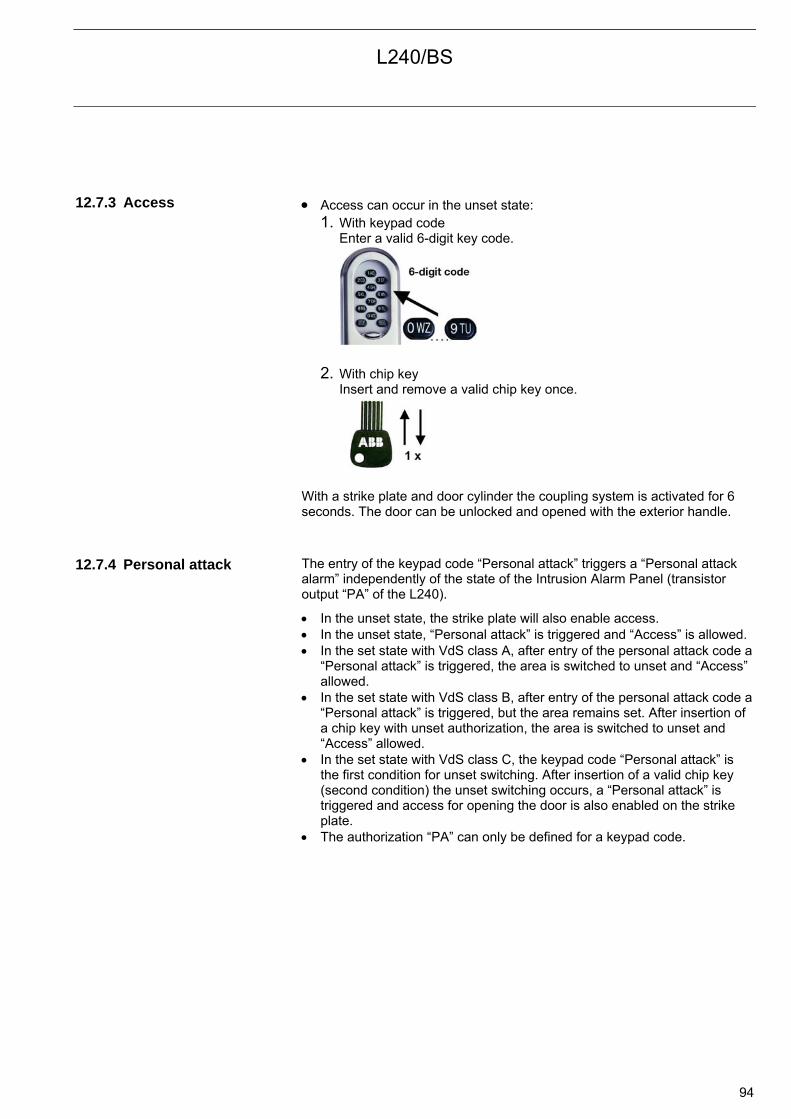
L240/BS
94
12.7.3 Access Access can occur in the unset state:
1. With keypad code Enter a valid 6-digit key code.
2. With chip key Insert and remove a valid chip key once.
With a strike plate and door cylinder the coupling system is activated for 6 seconds. The door can be unlocked and opened with the exterior handle.
12.7.4 Personal attack The entry of the keypad code “Personal attack” triggers a “Personal attack
alarm” independently of the state of the Intrusion Alarm Panel (transistor output “PA” of the L240).
In the unset state, the strike plate will also enable access. In the unset state, “Personal attack” is triggered and “Access” is allowed. In the set state with VdS class A, after entry of the personal attack code a
“Personal attack” is triggered, the area is switched to unset and “Access” allowed.
In the set state with VdS class B, after entry of the personal attack code a “Personal attack” is triggered, but the area remains set. After insertion of a chip key with unset authorization, the area is switched to unset and “Access” allowed.
In the set state with VdS class C, the keypad code “Personal attack” is the first condition for unset switching. After insertion of a valid chip key (second condition) the unset switching occurs, a “Personal attack” is triggered and access for opening the door is also enabled on the strike plate.
The authorization “PA” can only be defined for a keypad code.
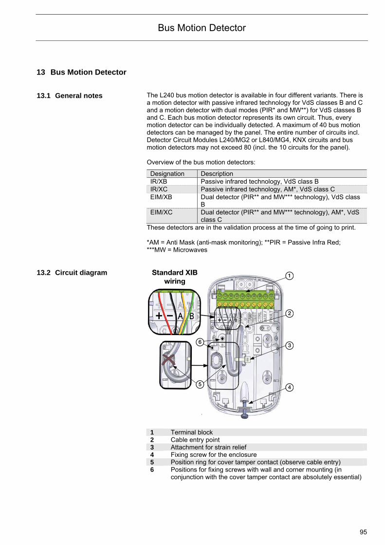
Bus Motion Detector
95
13 Bus Motion Detector 13.1 General notes The L240 bus motion detector is available in four different variants. There is
a motion detector with passive infrared technology for VdS classes B and C and a motion detector with dual modes (PIR* and MW**) for VdS classes B and C. Each bus motion detector represents its own circuit. Thus, every motion detector can be individually detected. A maximum of 40 bus motion detectors can be managed by the panel. The entire number of circuits incl. Detector Circuit Modules L240/MG2 or L840/MG4, KNX circuits and bus motion detectors may not exceed 80 (incl. the 10 circuits for the panel). Overview of the bus motion detectors:
Designation Description IR/XB Passive infrared technology, VdS class B IR/XC Passive infrared technology, AM*, VdS class C EIM/XB Dual detector (PIR** and MW*** technology), VdS class
B EIM/XC Dual detector (PIR** and MW*** technology), AM*, VdS
class C These detectors are in the validation process at the time of going to print. *AM = Anti Mask (anti-mask monitoring); **PIR = Passive Infra Red; ***MW = Microwaves
13.2 Circuit diagram Standard XIB
wiring1
2
3
45
6
.
1 Terminal block 2 Cable entry point 3 Attachment for strain relief 4 Fixing screw for the enclosure 5 Position ring for cover tamper contact (observe cable entry) 6 Positions for fixing screws with wall and corner mounting (in
conjunction with the cover tamper contact are absolutely essential)
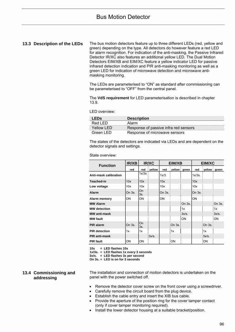
Bus Motion Detector
96
13.3 Description of the LEDs The bus motion detectors feature up to three different LEDs (red, yellow and green) depending on the type. All detectors do however feature a red LED for alarm recognition. For indication of the anti-masking, the Passive Infrared Detector IR/XC also features an additional yellow LED. The Dual Motion Detectors EIM/XB and EIM/XC feature a yellow indicator LED for passive infrared detection indication and PIR anti-masking monitoring as well as a green LED for indication of microwave detection and microwave anti-masking monitoring. The LEDs are parameterised to “ON” as standard after commissioning can be parameterised to “OFF” from the central panel. The VdS requirement for LED parameterisation is described in chapter 13.9. LED overview:
LEDs Description Red LED Alarm Yellow LED Response of passive infra red sensors Green LED Response of microwave sensors
The states of the detectors are indicated via LEDs and are dependent on the detector signals and settings. State overview:
IR/XB IR/XC EIM/XB EIM/XC Function
red red yellow red yellow green red yellow green
Anti-mask calibration 1x/3s. 1x/3. 1x/3s.
Teached-in 10x 10x 10x 10x
Low voltage 10x 10x 10x 10x Alarm On 3s. On
3s. On 3s. On 3s. Alarm memory ON ON ON ON
MW Alarm On 3s. On 3s.
MW detection 1x 1x MW anti-mask 3x/s. 3x/s. MW fault ON ON PIR alarm On 3s. On
3s. On 3s. On 3s. PIR detection 1x 1x 1x 1x PIR anti-mask 3x/s. 3x/s. PIR fault ON ON ON ON
10x = LED flashes 10x 1x/3s. = LED flashes 1x every 3 seconds 3x/s. = LED flashes 3x per second On 3s. = LED is on for 3 seconds
13.4 Commissioning and
addressing The installation and connection of motion detectors is undertaken on the panel with the power switched off. Remove the detector cover screw on the front cover using a screwdriver. Carefully remove the circuit board from the plug device. Establish the cable entry and insert the XIB bus cable. Provide the aperture of the position ring for the cover tamper contact
(only if cover tamper monitoring required). Install the lower detector housing at a suitable bracket/position.
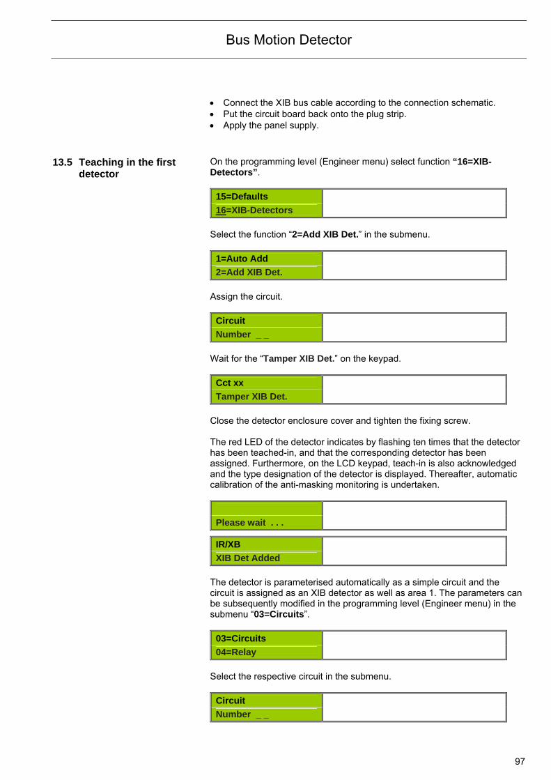
Bus Motion Detector
97
Connect the XIB bus cable according to the connection schematic. Put the circuit board back onto the plug strip. Apply the panel supply.
13.5 Teaching in the first
detector On the programming level (Engineer menu) select function “16=XIB-Detectors”.
15=Defaults
16=XIB-Detectors
Select the function “2=Add XIB Det.” in the submenu.
1=Auto Add
2=Add XIB Det.
Assign the circuit.
Circuit
Number _ _
Wait for the “Tamper XIB Det.” on the keypad.
Cct xx
Tamper XIB Det.
Close the detector enclosure cover and tighten the fixing screw. The red LED of the detector indicates by flashing ten times that the detector has been teached-in, and that the corresponding detector has been assigned. Furthermore, on the LCD keypad, teach-in is also acknowledged and the type designation of the detector is displayed. Thereafter, automatic calibration of the anti-masking monitoring is undertaken.
Please wait . . .
IR/XB
XIB Det Added
The detector is parameterised automatically as a simple circuit and the circuit is assigned as an XIB detector as well as area 1. The parameters can be subsequently modified in the programming level (Engineer menu) in the submenu “03=Circuits”.
03=Circuits
04=Relay
Select the respective circuit in the submenu.
Circuit
Number _ _
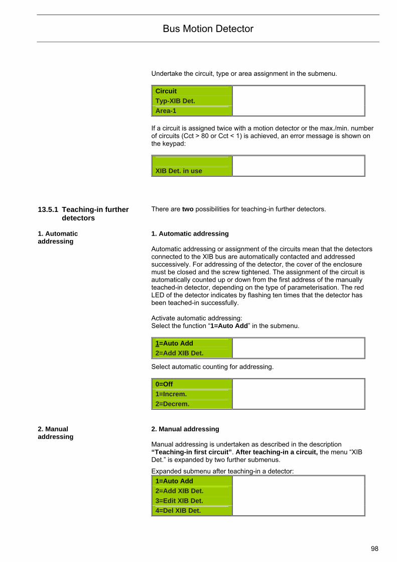
Bus Motion Detector
98
Undertake the circuit, type or area assignment in the submenu.
Circuit
Typ-XIB Det.
Area-1
If a circuit is assigned twice with a motion detector or the max./min. number of circuits (Cct > 80 or Cct < 1) is achieved, an error message is shown on the keypad:
XIB Det. in use
13.5.1 Teaching-in further
detectors There are two possibilities for teaching-in further detectors.
1. Automatic addressing
1. Automatic addressing Automatic addressing or assignment of the circuits mean that the detectors connected to the XIB bus are automatically contacted and addressed successively. For addressing of the detector, the cover of the enclosure must be closed and the screw tightened. The assignment of the circuit is automatically counted up or down from the first address of the manually teached-in detector, depending on the type of parameterisation. The red LED of the detector indicates by flashing ten times that the detector has been teached-in successfully. Activate automatic addressing: Select the function “1=Auto Add” in the submenu.
1=Auto Add
2=Add XIB Det.
Select automatic counting for addressing.
0=Off
1=Increm.
2=Decrem. 2. Manual addressing
2. Manual addressing Manual addressing is undertaken as described in the description “Teaching-in first circuit”. After teaching-in a circuit, the menu “XIB Det.” is expanded by two further submenus.
Expanded submenu after teaching-in a detector:
1=Auto Add
2=Add XIB Det.
3=Edit XIB Det.
4=Del XIB Det.
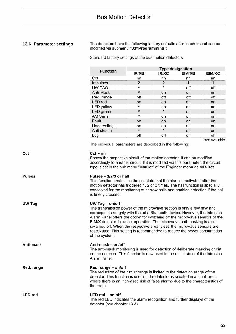
Bus Motion Detector
99
13.6 Parameter settings
The detectors have the following factory defaults after teach-in and can be modified via submenu “03=Programming”: Standard factory settings of the bus motion detectors:
Type designation Function
IR/XB IR/XC EIM/XB EIM/XC Cct nn nn nn nn Impulses 2 2 1 1 UW TAG * * off off Anti-Mask * on on on Red. range off off off off LED red on on on on LED yellow * on on on LED green * * on on AM Sens. * on on on Fault on on on on Undervoltage on on on on Anti stealth * * on on Log off off off off
*not availableThe individual parameters are described in the following:
Cct Cct – nn
Shows the respective circuit of the motion detector. It can be modified accordingly to another circuit. If it is modified via this parameter, the circuit type is set in the sub menu “03=Cct” of the Engineer menu as XIB-Det.
Pulses Pulses – 1/2/3 or hall
This function enables in the set state that the alarm is activated after the motion detector has triggered 1, 2 or 3 times. The hall function is specially conceived for the monitoring of narrow halls and enables detection if the hall is briefly crossed.
UW Tag UW Tag – on/off
The transmission power of the microwave section is only a few mW and corresponds roughly with that of a Bluetooth device. However, the Intrusion Alarm Panel offers the option for switching off the microwave sensors of the EIM/X detector for unset operation. The microwave anti-masking is also switched off. When the respective area is set, the microwave sensors are reactivated. This setting is recommended to reduce the power consumption of the system.
Anti-mask Anti-mask – on/off
The anti-mask monitoring is used for detection of deliberate masking or dirt on the detector. This function is now used in the unset state of the Intrusion Alarm Panel.
Red. range Red. range – on/off
The reduction of the circuit range is limited to the detection range of the detector. This function is useful if the detector is situated in a small area, where there is an increased risk of false alarms due to the characteristics of the room.
LED red LED red – on/off
The red LED indicates the alarm recognition and further displays of the detector (see chapter 13.3).
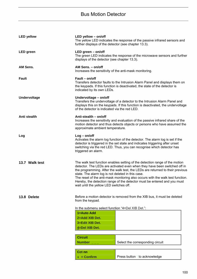
Bus Motion Detector
100
LED yellow LED yellow – on/off The yellow LED indicates the response of the passive infrared sensors and further displays of the detector (see chapter 13.3).
LED green LED green – on/off
The green LED indicates the response of the microwave sensors and further displays of the detector (see chapter 13.3).
AM Sens. AM Sens. – on/off
Increases the sensitivity of the anti-mask monitoring. Fault Fault – on/off
Transfers detector faults to the Intrusion Alarm Panel and displays them on the keypads. If this function is deactivated, the state of the detector is indicated by its own LEDs.
Undervoltage Undervoltage – on/off
Transfers the undervoltage of a detector to the Intrusion Alarm Panel and displays this on the keypads. If this function is deactivated, the undervoltage of the detector is indicated via the red LED.
Anti stealth Anti-stealth – on/off
Increases the sensitivity and evaluation of the passive infrared share of the motion detector and thus detects objects or persons who have assumed the approximate ambient temperature.
Log Log – on/off
Activates the alarm log function of the detector. The alarm log is set if the detector is triggered in the set state and indicates triggering after unset switching via the red LED. Thus, you can recognise which detector has triggered an alarm.
13.7 Walk test The walk test function enables setting of the detection range of the motion
detector. The LEDs are activated even when they have been switched off in the programming. After the walk test, the LEDs are returned to their previous state. The alarm log is not deleted in this case. The reset of the anti-mask monitoring also occurs with the walk test function.Hereby, the detection range of the detector must be entered and you must wait until the yellow LED switches off.
13.8 Delete Before a motion detector is removed from the XIB bus, it must be deleted
from the keypad. In the submenu select function “4=Del XIB Det.”:
1=Auto Add
2=Add XIB Det.
3=Edit XIB Det.
4=Del XIB Det.
Circuit
Number _ _ _ Select the corresponding circuit
Cct nn
4 = Confirm Press button ! to acknowledge
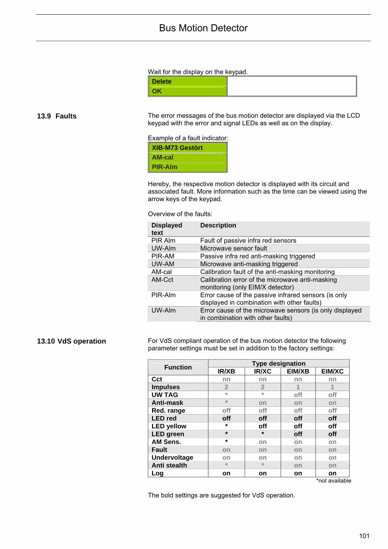
Bus Motion Detector
101
Wait for the display on the keypad.
Delete
OK 13.9 Faults The error messages of the bus motion detector are displayed via the LCD
keypad with the error and signal LEDs as well as on the display. Example of a fault indicator:
XIB-M73 Gestört
AM-cal
PIR-Alm
Hereby, the respective motion detector is displayed with its circuit and associated fault. More information such as the time can be viewed using the arrow keys of the keypad. Overview of the faults:
Displayed text
Description
PIR Alm Fault of passive infra red sensors UW-Alm Microwave sensor fault PIR-AM Passive infra red anti-masking triggered UW-AM Microwave anti-masking triggered AM-cal Calibration fault of the anti-masking monitoring AM-Cct Calibration error of the microwave anti-masking
monitoring (only EIM/X detector) PIR-Alm Error cause of the passive infrared sensors (is only
displayed in combination with other faults) UW-Alm Error cause of the microwave sensors (is only displayed
in combination with other faults) 13.10 VdS operation For VdS compliant operation of the bus motion detector the following
parameter settings must be set in addition to the factory settings:
Type designation Function
IR/XB IR/XC EIM/XB EIM/XC Cct nn nn nn nn Impulses 2 2 1 1 UW TAG * * off off Anti-mask * on on on Red. range off off off off LED red off off off off LED yellow * off off off LED green * * off off AM Sens. * on on on Fault on on on on Undervoltage on on on on Anti stealth * * on on Log on on on on
*not available The bold settings are suggested for VdS operation.
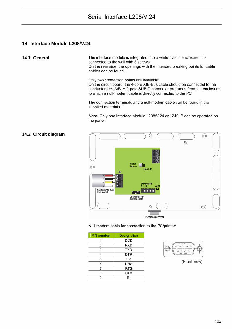
Serial Interface L208/V.24
102
14 Interface Module L208/V.24 14.1 General The interface module is integrated into a white plastic enclosure. It is
connected to the wall with 3 screws. On the rear side, the openings with the intended breaking points for cable entries can be found. Only two connection points are available: On the circuit board, the 4-core XIB-Bus cable should be connected to the conductors +/-/A/B. A 9-pole SUB-D connector protrudes from the enclosure to which a null-modem cable is directly connected to the PC. The connection terminals and a null-modem cable can be found in the supplied materials. Note: Only one Interface Module L208/V.24 or L240/IP can be operated on the panel.
14.2 Circuit diagram
Null-modem cable for connection to the PC/printer:
PIN number Designation 1 DCD 2 RXD 3 TXD 4 DTR 5 0V 6 DRS 7 RTS 8 CTS 9 RI
(Front view)
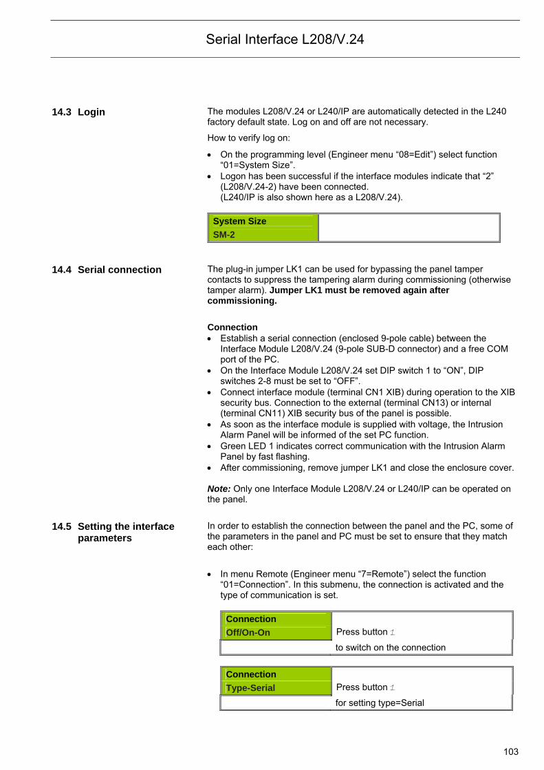
Serial Interface L208/V.24
103
14.3 Login The modules L208/V.24 or L240/IP are automatically detected in the L240
factory default state. Log on and off are not necessary.
How to verify log on:
On the programming level (Engineer menu “08=Edit”) select function “01=System Size”.
Logon has been successful if the interface modules indicate that “2” (L208/V.24-2) have been connected. (L240/IP is also shown here as a L208/V.24).
System Size
SM-2 14.4 Serial connection The plug-in jumper LK1 can be used for bypassing the panel tamper
contacts to suppress the tampering alarm during commissioning (otherwise tamper alarm). Jumper LK1 must be removed again after commissioning.
Connection Establish a serial connection (enclosed 9-pole cable) between the
Interface Module L208/V.24 (9-pole SUB-D connector) and a free COM port of the PC.
On the Interface Module L208/V.24 set DIP switch 1 to “ON”, DIP switches 2-8 must be set to “OFF”.
Connect interface module (terminal CN1 XIB) during operation to the XIB security bus. Connection to the external (terminal CN13) or internal (terminal CN11) XIB security bus of the panel is possible.
As soon as the interface module is supplied with voltage, the Intrusion Alarm Panel will be informed of the set PC function.
Green LED 1 indicates correct communication with the Intrusion Alarm Panel by fast flashing.
After commissioning, remove jumper LK1 and close the enclosure cover. Note: Only one Interface Module L208/V.24 or L240/IP can be operated on the panel.
14.5 Setting the interface parameters
In order to establish the connection between the panel and the PC, some of the parameters in the panel and PC must be set to ensure that they match each other:
In menu Remote (Engineer menu “7=Remote”) select the function
“01=Connection”. In this submenu, the connection is activated and the type of communication is set.
Connection
Off/On-On Press button 1
to switch on the connection
Connection
Type-Serial Press button 1
for setting type=Serial

Serial Interface L208/V.24
104
Connection
Baud-9600 Press button 1
for baud rate of 9600 Baud In submenu “02=Operations” the “Auto” parameter should be selected.
Operations
Enable-Auto Press button 2
to set enable to “Auto” In submenu “03=Auth Code” an enable code can be entered. As enable
occurs without code, this function is not relevant and no entries must be made.
Auth Code
Auth Code-000
In submenu “04=SiteID” a 4-digit customer number must be entered for
the panel. This customer number in the panel must be identical with the customer number in the database of the PC Software (WIN-PC). When communication is established, both customer numbers are compared and communication will only be possible if they are identical.
SiteID
1234 Entry of the customer number
15 LAN Interface L240/IP 15.1 General The connection of the L240 to the PC is implemented either via a serial
interface with the Interface Module L208/V.24 or via a LAN network with the IP Interface L240/IP. The IP Interface is installed in the same enclosure as module L208/V24. Two connections are also available here: On the circuit board, the 4-core XIB-Bus from the Intrusion Alarm Panel should be connected to the conductors +/-/A/B. A network socket can be found on the right side. On the additional connection “Keypad 0”, a L240/PT with address 0 can be connected and can be used to program the Intrusion Alarm Panel or to enable the connected interface module in the Hardware menu of the panel. Note: Only one Interface Module L208/V.24 or L240/IP can be operated on the panel at one time.
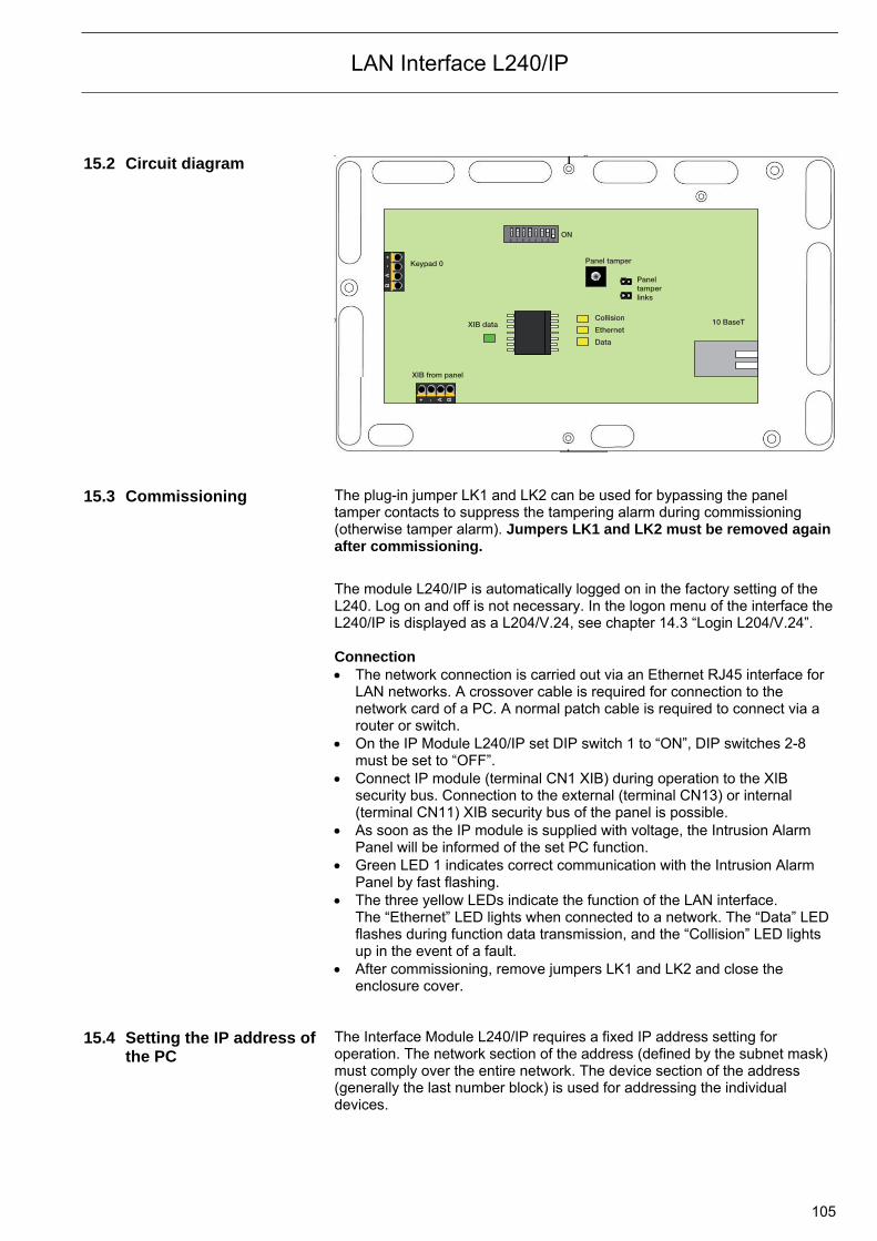
LAN Interface L240/IP
105
15.2 Circuit diagram
B
A
-
+
+ - A B
Keypad 0
XIB data
XIB from panel
8 7 6 5 4 3 2 1ON
Panel tamper
Panel tamper links
10 BaseTCollision
Ethernet
Data
15.3 Commissioning The plug-in jumper LK1 and LK2 can be used for bypassing the panel
tamper contacts to suppress the tampering alarm during commissioning (otherwise tamper alarm). Jumpers LK1 and LK2 must be removed again after commissioning.
The module L240/IP is automatically logged on in the factory setting of the L240. Log on and off is not necessary. In the logon menu of the interface the L240/IP is displayed as a L204/V.24, see chapter 14.3 “Login L204/V.24”. Connection The network connection is carried out via an Ethernet RJ45 interface for
LAN networks. A crossover cable is required for connection to the network card of a PC. A normal patch cable is required to connect via a router or switch.
On the IP Module L240/IP set DIP switch 1 to “ON”, DIP switches 2-8 must be set to “OFF”.
Connect IP module (terminal CN1 XIB) during operation to the XIB security bus. Connection to the external (terminal CN13) or internal (terminal CN11) XIB security bus of the panel is possible.
As soon as the IP module is supplied with voltage, the Intrusion Alarm Panel will be informed of the set PC function.
Green LED 1 indicates correct communication with the Intrusion Alarm Panel by fast flashing.
The three yellow LEDs indicate the function of the LAN interface. The “Ethernet” LED lights when connected to a network. The “Data” LED flashes during function data transmission, and the “Collision” LED lights up in the event of a fault.
After commissioning, remove jumpers LK1 and LK2 and close the enclosure cover.
15.4 Setting the IP address of
the PC
The Interface Module L240/IP requires a fixed IP address setting for operation. The network section of the address (defined by the subnet mask) must comply over the entire network. The device section of the address (generally the last number block) is used for addressing the individual devices.
LAN Interface L240/IP
106
In the example configuration, the following IP addresses are assumed (can vary according to the network):
PC: 192.168.3.1 L240/IP: 192.168.3.3 Gateway: 192.168.3.4 Generally, the properties of the Internet protocol for the PC settings are set to “Obtain an IP address automatically”. This setting must be checked and a fixed IP address setting may need to be set. The following example shows how the IP address of the computer is changed (Example: Windows XP). Note: The settings must be made by a person with appropriate experience in the configuration of PCs and network technology. Consult your system administrator if required. Access the network settings:
Start – Control Panel - Network and Internet Connections Double click on the respective network connection under LAN or High-
Speed Internet and click on Properties. The window >Properties of LAN Connection opens.
Select Internet Protocol (TCP/IP) from the list and click on Properties. Activate “Use the following IP address” and enter the new IP address (in
our example the IP address 192.168.3.1) and Subnet Mask. IMPORTANT: Note the old IP setting so that you can reactivate it!
15.5 Setting the network
parameters on the L240 The IP addresses and further specification must correspond with one another in the Intrusion Alarm Panel and in WIN-PC.
In menu Remote (Engineer menu “7=Remote”), select the function “01=Connection”. In this submenu, the connection is activated and the type of communication is set. Select “Ethernet”.
Connection
Off/On-On Press button 1
to switch on the connection Connection
Type-Ethernet Press button 2
to set type=Ethernet In submenu “02=Enable”, the “Auto” parameter should be selected.
Operations
Enable-Auto Press button 2
to set enable to “Auto” In submenu “03=Auth Code”, an enable code can be entered. As enable
occurs without code, this function is not relevant and no entries must be made.
Auth Code
Auth Code-000
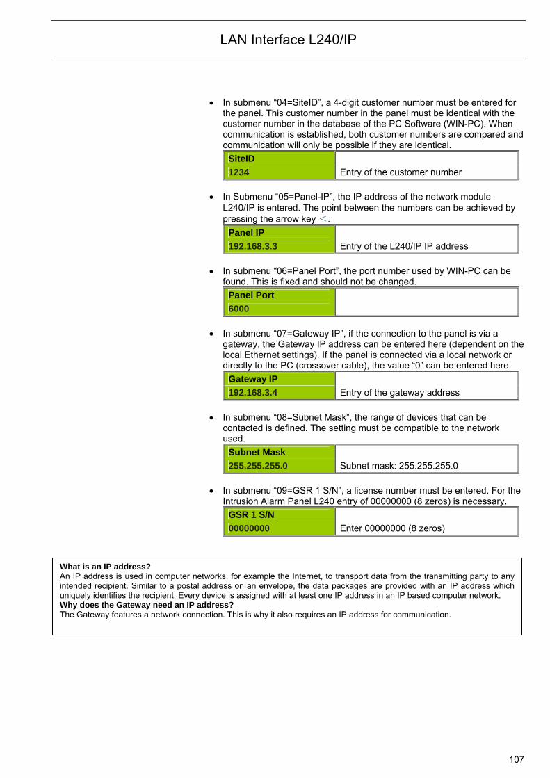
LAN Interface L240/IP
107
In submenu “04=SiteID”, a 4-digit customer number must be entered for the panel. This customer number in the panel must be identical with the customer number in the database of the PC Software (WIN-PC). When communication is established, both customer numbers are compared and communication will only be possible if they are identical.
SiteID
1234 Entry of the customer number In Submenu “05=Panel-IP”, the IP address of the network module
L240/IP is entered. The point between the numbers can be achieved by pressing the arrow key <.
Panel IP
192.168.3.3 Entry of the L240/IP IP address In submenu “06=Panel Port”, the port number used by WIN-PC can be
found. This is fixed and should not be changed.
Panel Port
6000
In submenu “07=Gateway IP”, if the connection to the panel is via a
gateway, the Gateway IP address can be entered here (dependent on the local Ethernet settings). If the panel is connected via a local network or directly to the PC (crossover cable), the value “0” can be entered here.
Gateway IP
192.168.3.4 Entry of the gateway address In submenu “08=Subnet Mask”, the range of devices that can be
contacted is defined. The setting must be compatible to the network used.
Subnet Mask
255.255.255.0 Subnet mask: 255.255.255.0 In submenu “09=GSR 1 S/N”, a license number must be entered. For the
Intrusion Alarm Panel L240 entry of 00000000 (8 zeros) is necessary.
GSR 1 S/N
00000000 Enter 00000000 (8 zeros)
What is an IP address? An IP address is used in computer networks, for example the Internet, to transport data from the transmitting party to any intended recipient. Similar to a postal address on an envelope, the data packages are provided with an IP address which uniquely identifies the recipient. Every device is assigned with at least one IP address in an IP based computer network. Why does the Gateway need an IP address? The Gateway features a network connection. This is why it also requires an IP address for communication.
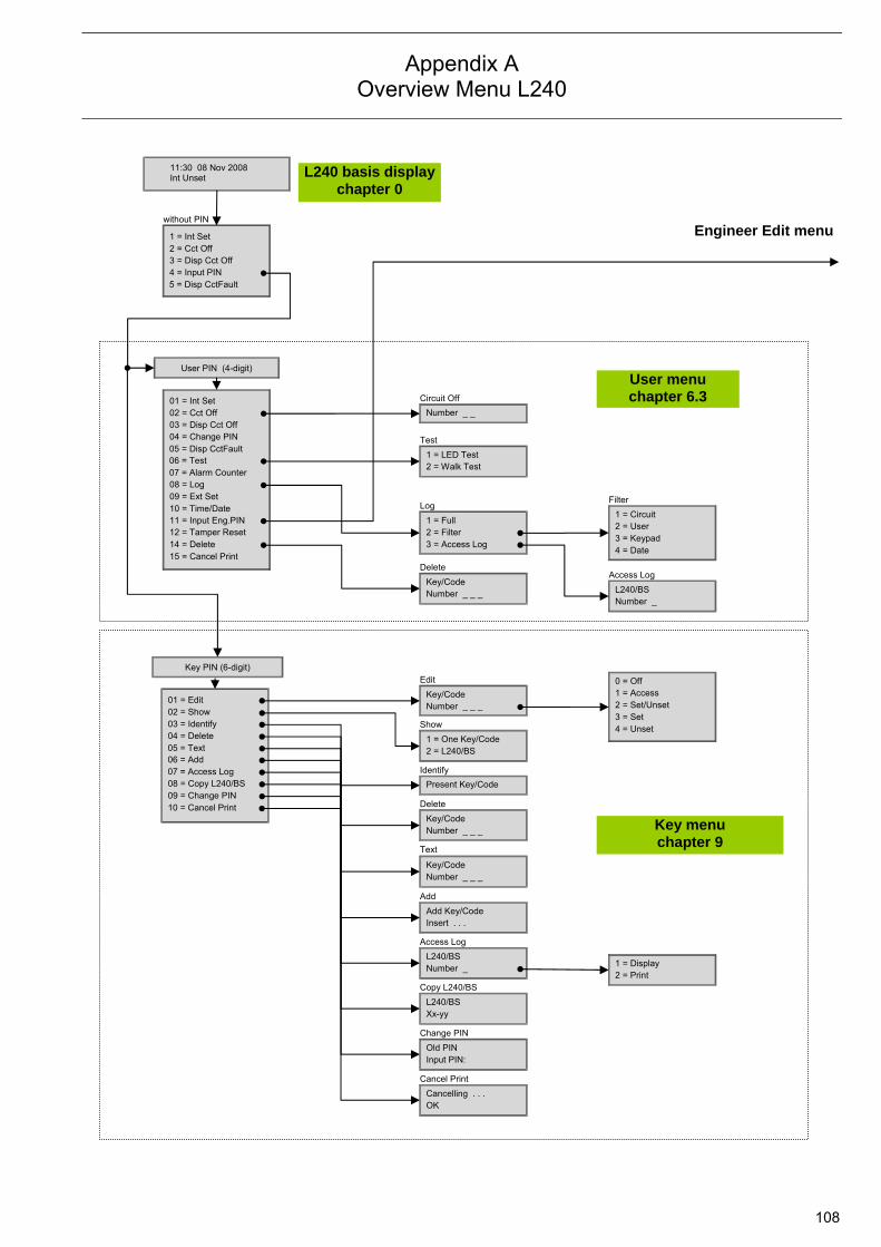
Appendix A Overview Menu L240
108
11:30 08 Nov 2008 Int Unset
without PIN
User PIN (4-digit)
01 = Int Set 02 = Cct Off 03 = Disp Cct Off 04 = Change PIN 05 = Disp CctFault 06 = Test 07 = Alarm Counter 08 = Log 09 = Ext Set 10 = Time/Date 11 = Input Eng.PIN 12 = Tamper Reset 14 = Delete
Number _ _
1 = LED Test 2 = Walk Test
1 = Full 2 = Filter 3 = Access Log
Key/Code Number _ _ _ L240/BS
Number _
1 = Circuit 2 = User 3 = Keypad 4 = Date
1 = Int Set 2 = Cct Off 3 = Disp Cct Off 4 = Input PIN 5 = Disp CctFault
Key PIN (6-digit)
01 = Edit 02 = Show 03 = Identify 04 = Delete 05 = Text 06 = Add 07 = Access Log 08 = Copy L240/BS 09 = Change PIN
Key/Code Number _ _ _
0 = Off 1 = Access 2 = Set/Unset 3 = Set 4 = Unset
1 = One Key/Code 2 = L240/BS
Present Key/Code
Key/CodeNumber _ _ _
Key/CodeNumber _ _ _
Add Key/CodeInsert . . .
L240/BS Number _
L240/BS Xx-yy
1 = Display 2 = Print
Old PIN Input PIN:
Circuit Off
Test
Log
Delete
Filter
Access Log
Edit
Show
Identify
Delete
Text
Add
Access Log
Copy L240/BS
Change PIN
L240 basis displaychapter 0
User menu chapter 6.3
Key menu chapter 9
Engineer Edit menu
15 = Cancel Print
10 = Cancel Print
Cancelling . . . OK
Cancel Print
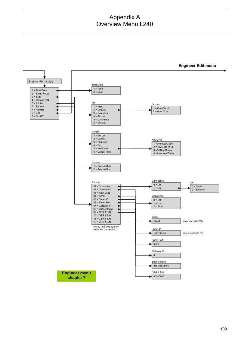
Appendix A Overview Menu L240
109
Engineer-PIN (6-digit)
1 = Time/Date 2 = Tamp Reset 3 = Test 4 = Change PIN 5 = Printer 6 = Service 7 = Remote 8 = Edit 9 = Cct Off
1 = Time 2 = Date
1 = Print 2 = Circuits 3 = Sounders
1 = One Circuit 2 = Area Ccts
Time/Date
Test Circuits
Engineer menu chapter 7
6 = System 5 = L240/B/BS 4 = Strobe
1 = Set Up 2 = Config 3 = Changes
1 =One Key/Code 2 =Key/Code in BL
Printer
Key/Code
5 = Key/Code 4 = Text
4 =Area Key/Codes 3 =All Key/Codes
1 = Service Date 2 = Service Num
Service
01 = Connection 02 = Operations 03 = Auth Code
Remote
04 = SiteID
08 = Subnet Mask 07 = Gateway IP 06 = Panel Port 05 = Panel IP
12 = GSR 4 S/N 11 = GSR 3 S/N 10 = GSR 2 S/N 09 = GSR 1 S/N
(Menu items 05-12 only with LAN connection)
1 = Serial
On
2 = Ethernet 0 = Off
1 = On
Connection
0 = Off 1 = User
Operations
2 = Auto
SiteID
SiteID
192.168.3.3
Panel IP
6000
Panel Port
0
Gateway IP
255.255.255.0
Subnet Mask
00000000
GSR 1 S/N
(here: example IP)
Engineer Edit menu
6 = Cancel Print
(see also WINPC)
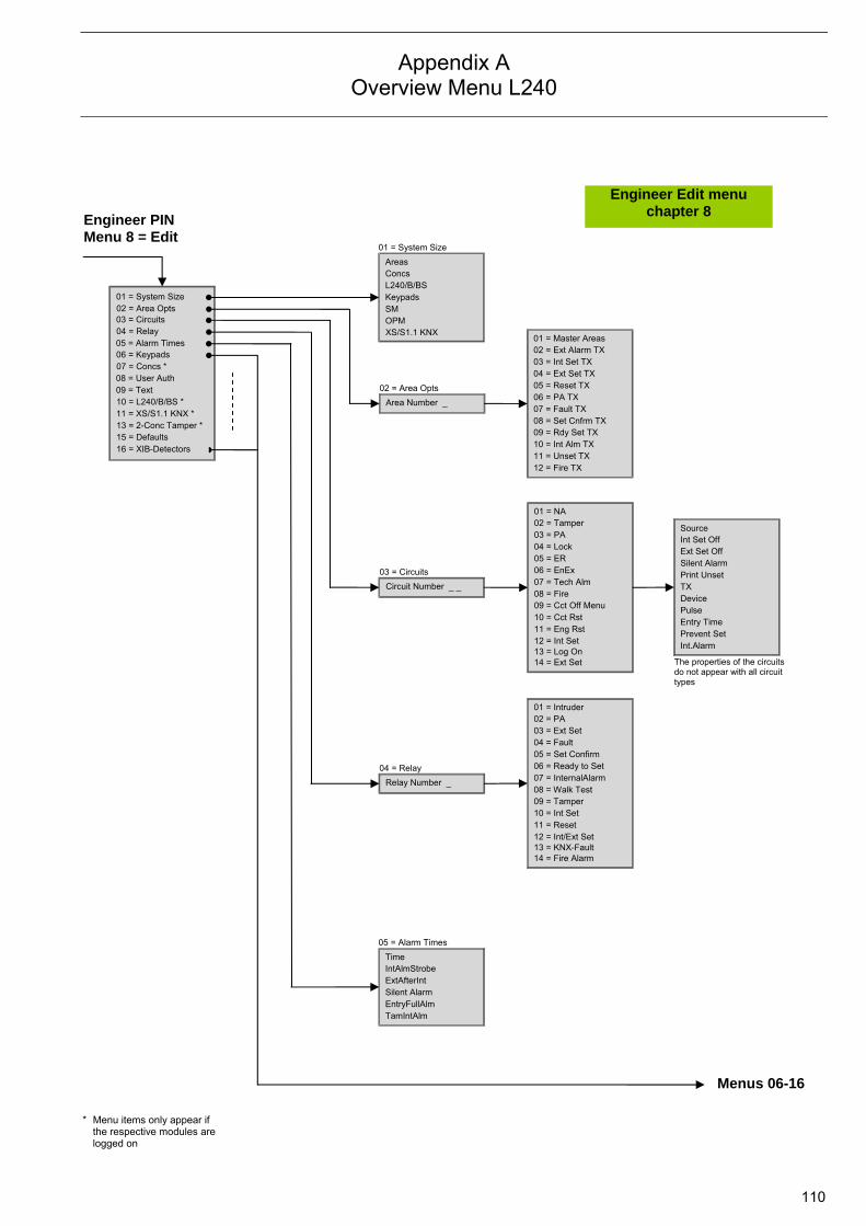
Appendix A Overview Menu L240
110
01 = System Size 02 = Area Opts 03 = Circuits 04 = Relay 05 = Alarm Times 06 = Keypads 07 = Concs * 08 = User Auth 09 = Text
Area Number _
Areas Concs L240/B/BS
02 = Area Opts
01 = System Size
OPM SM Keypads
01 = Master Areas 02 = Ext Alarm TX 03 = Int Set TX 04 = Ext Set TX
08 = Set Cnfrm TX 07 = Fault TX 06 = PA TX 05 = Reset TX
12 = Fire TX 11 = Unset TX 10 = Int Alm TX 09 = Rdy Set TX
10 = L240/B/BS * 11 = XS/S1.1 KNX * 13 = 2-Conc Tamper * 15 = Defaults
01 = NA 02 = Tamper 03 = PA 04 = Lock
08 = Fire 07 = Tech Alm 06 = EnEx 05 = ER
12 = Int Set 11 = Eng Rst 10 = Cct Rst 09 = Cct Off Menu
Int Set Off Ext Set Off Silent Alarm
Device TX Print Unset
Time IntAlmStrobe ExtAfterInt
05 = Alarm Times
TamIntAlm EntryFullAlm Silent Alarm
Circuit Number _ _
03 = Circuits
Relay Number _
04 = Relay
* Menu items only appear if the respective modules are logged on
XS/S1.1 KNX
14 = Ext Set 13 = Log On
Pulse
Int.Alarm Prevent Set Entry Time
The properties of the circuits do not appear with all circuit types
01 = Intruder 02 = PA 03 = Ext Set 04 = Fault
08 = Walk Test 07 = InternalAlarm 06 = Ready to Set 05 = Set Confirm
12 = Int/Ext Set 11 = Reset 10 = Int Set 09 = Tamper
14 = Fire Alarm 13 = KNX-Fault
Source
Menus 06-16
Engineer PIN Menu 8 = Edit
Engineer Edit menu chapter 8
16 = XIB-Detectors
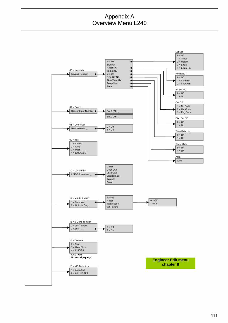
Appendix A Overview Menu L240
111
1 = Standard 2 = Outputs Only
11 = XS/S1.1 KNX
2 = Text 15 = Defaults
3 = User PINs
0 = Off 1 = Summer2 = Snd+Alm
Area _
1 = Circuit 2 = Area 3 = User
09 = Text
4 = L240/B/BS
Unset Door-CCT Lock-CCT
Area Tamper ElecBoltLock
ExtSet Reset Tamp.Sabo Sig Failure
Keypad Number _
06 = Keypads
Ext Set Bleeper Reset NC
Disp Cct NC Cct Off Int Set NC
0 = Off 1 = On
0 = Off 1 = Timed 2 = Instant
4 = EnEx/Tm 3 = EnEx
1 = No Code 2 = Usr Code3 = Eng Code
0 = Off 1 = On
0 = Off 1 = On
0 = Off 1 = On
Bat.1 (Ah) _
2-Conc Tamper 2-Conc. _ _
13 = 2-Conc Tamper
Area Tamp/User Time/Date Usr
Ext Set
Area
Reset NC
Int Set NC
Cct Off
Disp Cct NC
Time/Date Usr
Tamp User
Concentrator Number
07 = Concs
User Number _
08 = User Auth
Bat.2 (Ah) _
0 = Off1 = On
0 = Off1 = On
4 = L240/BS
0 = Off1 = On
CAUTION: No security query!
1 = Auto Add 2 = Add XIB Det
16 = XIB Detectors
Engineer Edit menu chapter 8
L240/BS Number _
10 = L240/B/BS

Appendix B Programming Example
112
Programming example In a building, the apartment (area 2/main area) and the office (area 1/lower level) of the owner are located. The office also has an external access door. It is necessary to ensure that the building alarm can only be set if the office has been set beforehand. Should the building intruder alarm be disarmed, the office will remain set. In the office, the window is monitored with a magnetic reed contact and glass break sensor (1 x Detector Circuit Module, 2-fold L240/MG2). Furthermore, the area is monitored with a Motion Detector IR/B L240/IR-XB. Setting is performed with a SafeKey Evaluation Module L240/BS. A Keypad L240/PT is located in the room for operation and display. In the apartment, the window is monitored with a magnetic reed contact and glass break sensor (2 x Detector Circuit Module, 2-fold L240/MG2 and 2 x Detector Circuit Module, 4-fold L840/MG4). Two Motion Detectors L240/IR/XB monitor the hallways. Setting is performed with a SafeKey Evaluation Module L240/BS. Operation and display is undertaken with two Keypads L240/PT. Addressing: The bus modules are addressed as follows using DIP switches/jumpers: Type XIB address
L240/MG2 office Detector module 01
L240/MG2 apartment 1 Detector module 02
L240/MG2 apartment 2 Detector module 03
L840/MG4 apartment 3 Detector module 04
L840/MG4 apartment 4 Detector module 05
L240/PT office Keypad 1
L240/PT apartment 1 Keypad 2
L240/PT apartment 2 Keypad 3
L240/BS office Evaluation module 01
L240/BS apartment Evaluation module 02
Programming: Access to the Edit level with the Engineer PIN (see chapter 7). In menu item “01=System Size” register the number of bus devices:
System Size
Areas-2 Press button 2 Concs-05 Press button 0 and 5 L240/B/BS-02 Press button 0 and 2 Keypads-3 Press button 3 SM-2 Press button 2
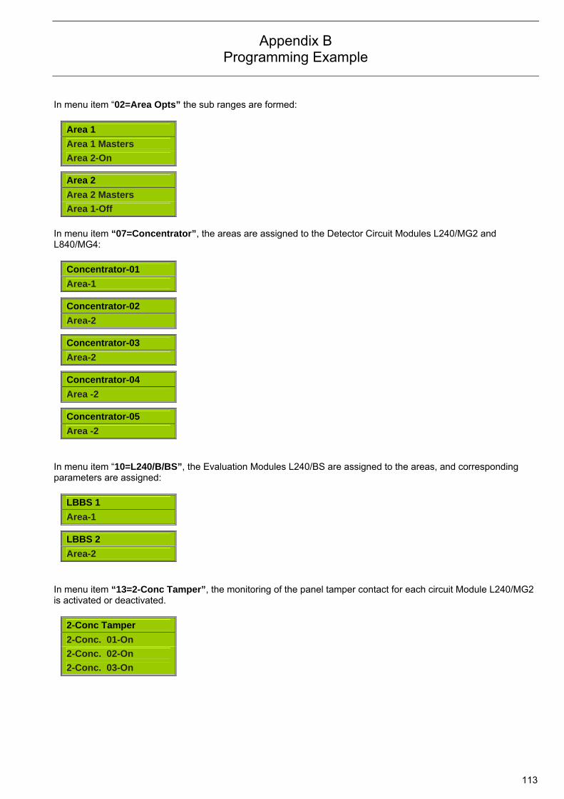
Appendix B Programming Example
113
In menu item “02=Area Opts” the sub ranges are formed:
Area 1
Area 1 Masters
Area 2-On
Area 2
Area 2 Masters
Area 1-Off
In menu item “07=Concentrator”, the areas are assigned to the Detector Circuit Modules L240/MG2 and L840/MG4:
Concentrator-01
Area-1
Concentrator-02
Area-2
Concentrator-03
Area-2
Concentrator-04
Area -2
Concentrator-05
Area -2
In menu item “10=L240/B/BS”, the Evaluation Modules L240/BS are assigned to the areas, and corresponding parameters are assigned:
LBBS 1
Area-1
LBBS 2
Area-2
In menu item “13=2-Conc Tamper”, the monitoring of the panel tamper contact for each circuit Module L240/MG2 is activated or deactivated.
2-Conc Tamper
2-Conc. 01-On
2-Conc. 02-On
2-Conc. 03-On

Appendix C System Protocol
114
1 Degree of expansion
Device Panel L240
Keypad L240/PT
Detector module L240/MG2
Detector module L840/MG4
Motion detector L240/IR/XB
Number 1
Evaluation module L240/BS
Serial interface L208/V24
Interface module L240/IP
2 Configuration of the detector circuits Cct. No. Type delivered state Type with divergent
programming Remarks
1 Intrusion cct off with int. set
2 Intrusion cct off with int. set
3 Intrusion cct off with int. set
4 Intrusion cct
5 Intrusion cct
6 Intrusion cct
7 Lock cct
8 Personal attack cct
9 Tampering circuit
10 Ext. Setting circuit
3 Configuration of the outputs Output No.
Type delivered state Type with divergent programming
Remarks
19, 20, 21 External set
22, 23, 24 Walk test

Appendix C System Protocol
115
4 Measured values main circuit board Terminals Function Setpoint Actual
(Date) Actual (Date)
Actual (Date)
Actual (Date)
Actual (Date)
V+/V- System voltage 14 V
Battery
Charging voltage 13.8 V
1-C Cct 1 5.8 – 6.2 V
2-C Cct 2 5.8 – 6.2 V
3-C Cct 3 5.8 – 6.2 V
4-C Cct 4 5.8 – 6.2 V
5-C Cct 5 5.8 – 6.2 V
6-C Cct 6 5.8 – 6.2 V
7-C Cct 7 0 V
8-C Cct 8 5.8 – 6.2 V
9-C Cct 9 5.8 – 6.2 V
10-C Cct 10 Set 6.4 – 6.8 V Unset 5.8 – 6.2 V
28-29 Strobe light 0.67 – 0.73 V
30-32 Siren 1 0.67 – 0.73 V
31-32 Siren 2 0.67 – 0.73 V
33-36 Comm fail fault 0 V
34-36 Comm fault alarm 0 V
35-36 Panel tamper 0 V

Kontakt
Note:We reserve the right to make technical changes or
modify the contents of this document without prior
notice. With regard to purchase orders, the agreed
particulars shall prevail.
ABB AG does not accept any responsibility
whatsoever for potential errors or possible lack of
information in this document.
We reserve all rights in this document and in the
subject matter and illustrations contained therein.
Any reproduction, disclosure to third parties or
utilization of its contents - in whole or in parts - is
forbidden without prior written consent of ABB AG.
Copyright© 2010 ABB
All rights reserved
Your ABB partner
www.abb.com/knx
Ord
er
Num
ber
2C
DC
54
1 1
52
D0
20
1 p
rinte
d in G
erm
any (0
5/1
0-0
.1-Z
VD
)

![KNX city - SEMCAB1]… · 3 KNX city KNX city 4 KNX and its comprehensive systems approach in sustainable city buildings The future focus of KNX will lie on buildings, mobility, infrastructure,](https://img.pdfslide.us/doc/110x75/5bb1ed1109d3f255638e32c8/knx-city-1-3-knx-city-knx-city-4-knx-and-its-comprehensive-systems-approach.jpg)


![Energy Efficiency with KNX - KNX Association [Official website]](https://img.pdfslide.us/doc/110x75/613d232b736caf36b759c1df/energy-efficiency-with-knx-knx-association-official-website.jpg)