Embed Size (px)
Citation preview

7/21/2019 SectionC_General.pdf
http://slidepdf.com/reader/full/sectioncgeneralpdf 1/8AXIAL FLOW FANS PERFORMANCE DATA
AXIAL FLOW FANS GENERAL INFORMATION
C-2 © FANTECH 2008
ELTA IMPELLER RANGE
The Elta impeller ranges included in this catalogue have harnessed the latest
technology in axial impeller design, resulting in enhanced pressure development,
efficiency and noise levels.
There are three main ranges: -
Elta 1000: 315 to 1000mm diameter using 150 or 250mm diameter hubs.
Elta 1400: 800 to 1400mm diameter using 255 or 350mm diameter hubs.
Elta 2000: 1250 to 2000mm diameter using 400 or 550mm diameter hubs.
For performances beyond those detailed in this catalogue, and for applications such as
mine and tunnel ventilation, please refer to our sales engineers for information.
AXIAL INTRODUCTION
This section of the catalogue details the performances of a wide range of axial flow fan
types as follows:-
The above fans range in diameter from 315mm to 2000mm.
TEST STANDARDS
The International Standards Organisation (ISO) achieved a standardised fan test code
with the publication of ISO5801:1997. This Standard replaces BS848:Part 1, 1980 upon
which it was based.
Fan performances for the Elta 1000 Series diameter have been aerodynamically tested
to BS848:Part 1, 1980 and the Elta 1400 and 2000 Series to ISO5801:1997. All three
series have been tested to BS848:Part 2, 1985 for sound performance.
The main difference between the above Standards and those they replaced, is the
installation Types A, B, C and D such that, if a fan unit is designed for use in any one of
these arrangements, the variation in performance should be established and shown.
Both BS848:Part 1, 1980 and ISO5801:1997 reflect the latest understanding of
measuring techniques and accuracy in fan performance testing.
If the same fans were tested to pre-1980 air flow and noise Standards and then to the
latest Standards, different performances would be obtained. The results from the later
Standards give differences of as much as:-
-5% in volume -10% in pressure -5% in efficiency +2 to 6dB in noise
These differences should be borne in mind when making comparisons of fans tested to
the different Standards, as they are the result of the test method and not the product.
V
V V
V
TYPE A
Free inletFree outlet
TYPE C
Ducted inletFree outlet
TYPE B
Free inletDucted outlet
TYPE D
Ducted inletDucted outlet
Duct Mounted Axial Fans AP Series - direct driven
APS Series - direct driven, smoke spill APB Series - belt-driven BFA Series - bifurcated, direct driven
Wall Mounted Fans SQ Series - square plate, direct driven
Axial Roof Units RDE Series - downflow cowl, exhaust
RDS Series - downflow cowl, supply RVE Series - vertical discharge RSS Series - vertical discharge, smoke
spill HC Series - high capacity, vertical
discharge SS Series - smoke spill
7/21/2019 SectionC_General.pdf
http://slidepdf.com/reader/full/sectioncgeneralpdf 2/8© FANTECH 2008 C-3AXIAL FLOW FANS PERFORMANCE DATA
AXIAL FLOW FANS GENERAL INFORMATION
C
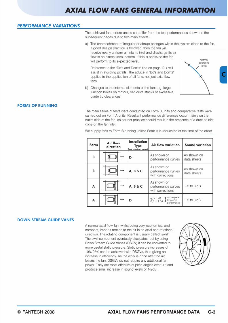
PERFORMANCE VARIATIONS
The achieved fan performances can differ from the test performances shown on the
subsequent pages due to two main effects:-
a) The encroachment of irregular or abrupt changes within the system close to the fan.
If good design practice is followed, then the fan will
receive nearly uniform air into its inlet and discharge its air
flow in an almost ideal pattern. If this is achieved the fanwill perform to its expected level.
Reference to the "Do's and Don'ts" tips on page O-1 will
assist in avoiding pitfalls. The advice in "Do's and Don'ts"
applies to the application of all fans, not just axial flow
fans.
b) Changes to the internal elements of the fan: e.g. large
junction boxes on motors, belt drive stacks or excessive
blade tip clearances.
FORMS OF RUNNING
The main series of tests were conducted on Form B units and comparative tests were
carried out on Form A units. Resultant performance differences occur mainly on the
outlet side of the fan, as correct practice should result in the presence of a duct or inlet
cone on the fan inlet.
We supply fans to Form B running unless Form A is requested at the time of the order.
DOWN STREAM GUIDE VANES
A normal axial flow fan, whilst being very economical andcompact, imparts motion to the air in an axial and rotational
direction. The rotating component is usually called ‘swirl’.
The swirl component eventually dissipates, but by using
Down Stream Guide Vanes (DSGV) it can be converted to
more useful static pressure. Static pressure increases of
10%-25% can be achieved with DSGVs, thus giving an
increase in efficiency. As the work is done after the air
leaves the fan, DSGVs do not require any additional fan
power. They are most effective at pitch angles over 20° and
produce small increase in sound levels of 1-2dB.
Normaloperating
range
InstallationType
(see previous page)
Form Air flow variation Sound variation
B D As shown on
performance curves
As shown on
data sheets
As shown on
performance curveswith corrections
As shown ondata sheets
A, B & C
A, B & C +2 to 3 dB
+2 to 3 dBD
B
A
A q
P V
S
× 1.02F × 1.04
as comparedto type ‘D’performance
As shown on
performance curveswith corrections
Air flow direction

7/21/2019 SectionC_General.pdf
http://slidepdf.com/reader/full/sectioncgeneralpdf 3/8AXIAL FLOW FANS PERFORMANCE DATA
AXIAL FLOW FANS GENERAL INFORMATION
C-4 © FANTECH 2008
MULTI-STAGE AXIAL FLOW FANS
Multi-stage axial fans with contra-rotating impellers can be supplied up to 1400mm diameter.
A two-stage assembly develops approximately 2.4 times the pressure developed by a
single-stage fan and increases the overall sound level by 8 to 10 dB.
To select a contra-rotating axial fan from the curves in this catalogue, divide the
specified static pressure by 2.4 and then select as though it were a single-stage unit.
The kW derived is for one stage only and the noise level will be 8 to 10 dB higher thanthe single-stage fan.
NOTE: Reference should be made to Fantech for complete selections of these fan
arrangements. Alternatively selections can be made using our Fans by Fantech product
selection CD.
FAN SPECIFICATION - IMPELLERS
Blades
The blades have been designed for optimal performance, for both aerodynamic needs as
well as noise characteristics. They are available in a range of materials as shown below:-
Impeller Ranges
The stress limits of the blades vary from one material to another and simplified criteria
are incorporated on the curves. However, if selecting fans using our interactive product
selection CD, you may find solutions with higher pitch angles are chosen; theseselections are quite acceptable.
It should be noted that, as we are constantly reviewing the materials we use, these
limits may be extended.
Hubs
All hubs use Fantech TECH-LOCK® taper bushes as standard with one exception. The
bush ensures ease of fitting and removal of the impeller from the motor shaft should
adjustment of the pitch angle, cleaning or repair of the impeller prove necessary. The
exception is for bores above 65mm and 85mm diameter for the 400mm and 550mm
diameter hubs respectively. In these cases we supply impellers with simple through-bores.
Fixings
All impellers are assembled using high-tensile, zinc-plated set screws and self-locking nuts.
HandingRight and left-hand blades are available enabling the selection of contra-rotating or
multi-stage axial flow fans up to 1400mm diameter. If contra-rotating fans of a larger
diameter are required please refer to our sales department.
Standard Material
GRP blades will be supplied for normal clean ventilation applications as standard
except where otherwise specified, or where local regulations prohibit their use.
Balance
The balance of all impellers is carefully checked to ensure vibration-free running.
Fully-adjustable Blades
All impeller pitch-angles are fully adjustable. For the Elta Range, up to size 1400, the
required blade angles are set on jigs but for sizes up to 1000 may also be set utilising
the graduated scale at the root of each blade. For the Elta 2000 Range pitch angle
setting is by protractor.
Range of
diameters No of blades
Hub Dia
mm Materials
315 to 900 5 or 10 150 GRP, Nylon, Alum. or Anti-static GRP
560 to 1000 7 or 14 250 GRP, Nylon, Alum. or Anti-static GRP
800 to 1250 3 or 6 255 GRP, Nylon, Alum. or Anti-static GRP
800 to 1400 3, 6, 9 or 12 350 GRP, Nylon, Alum. or Anti-static GRP
1000 to 1800 3, 6 or 9 400 GRP or Aluminium
1250 to 2000 3, 6, 9 or 12 550 GRP or Aluminium
7/21/2019 SectionC_General.pdf
http://slidepdf.com/reader/full/sectioncgeneralpdf 4/8© FANTECH 2008 C-5AXIAL FLOW FANS PERFORMANCE DATA
AXIAL FLOW FANS GENERAL INFORMATION
C
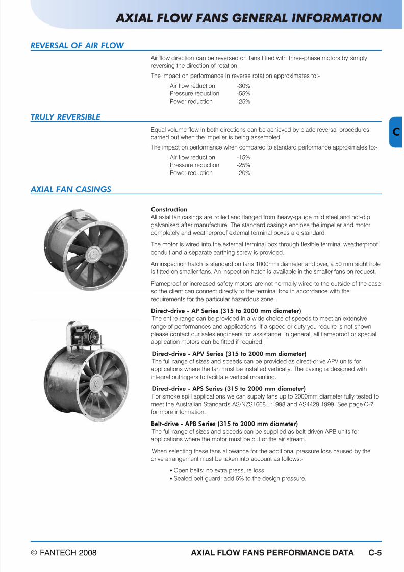
AXIAL FAN CASINGS
Construction
All axial fan casings are rolled and flanged from heavy-gauge mild steel and hot-dip
galvanised after manufacture. The standard casings enclose the impeller and motor
completely and weatherproof external terminal boxes are standard.
The motor is wired into the external terminal box through flexible terminal weatherproof
conduit and a separate earthing screw is provided.
An inspection hatch is standard on fans 1000mm diameter and over, a 50 mm sight hole
is fitted on smaller fans. An inspection hatch is available in the smaller fans on request.
Flameproof or increased-safety motors are not normally wired to the outside of the case
so the client can connect directly to the terminal box in accordance with the
requirements for the particular hazardous zone.
Direct-drive - AP Series (315 to 2000 mm diameter)
The entire range can be provided in a wide choice of speeds to meet an extensive
range of performances and applications. If a speed or duty you require is not shown
please contact our sales engineers for assistance. In general, all flameproof or special
application motors can be fitted if required.
Direct-drive - APV Series (315 to 2000 mm diameter)
The full range of sizes and speeds can be provided as direct-drive APV units for
applications where the fan must be installed vertically. The casing is designed with
integral outriggers to facilitate vertical mounting.
Direct-drive - APS Series (315 to 2000 mm diameter)
For smoke spill applications we can supply fans up to 2000mm diameter fully tested to
meet the Australian Standards AS/NZS1668.1:1998 and AS4429:1999. See page C-7
for more information.
Belt-drive - APB Series (315 to 2000 mm diameter)
The full range of sizes and speeds can be supplied as belt-driven APB units for
applications where the motor must be out of the air stream.
When selecting these fans allowance for the additional pressure loss caused by the
drive arrangement must be taken into account as follows:-
Open belts: no extra pressure loss Sealed belt guard: add 5% to the design pressure.
REVERSAL OF AIR FLOW
Air flow direction can be reversed on fans fitted with three-phase motors by simply
reversing the direction of rotation.
The impact on performance in reverse rotation approximates to:-
Air flow reduction -30%
Pressure reduction -55%
Power reduction -25%
TRULY REVERSIBLE
Equal volume flow in both directions can be achieved by blade reversal procedures
carried out when the impeller is being assembled.
The impact on performance when compared to standard performance approximates to:-
Air flow reduction -15%
Pressure reduction -25%
Power reduction -20%
7/21/2019 SectionC_General.pdf
http://slidepdf.com/reader/full/sectioncgeneralpdf 5/8AXIAL FLOW FANS PERFORMANCE DATA
AXIAL FLOW FANS GENERAL INFORMATION
C-6 © FANTECH 2008
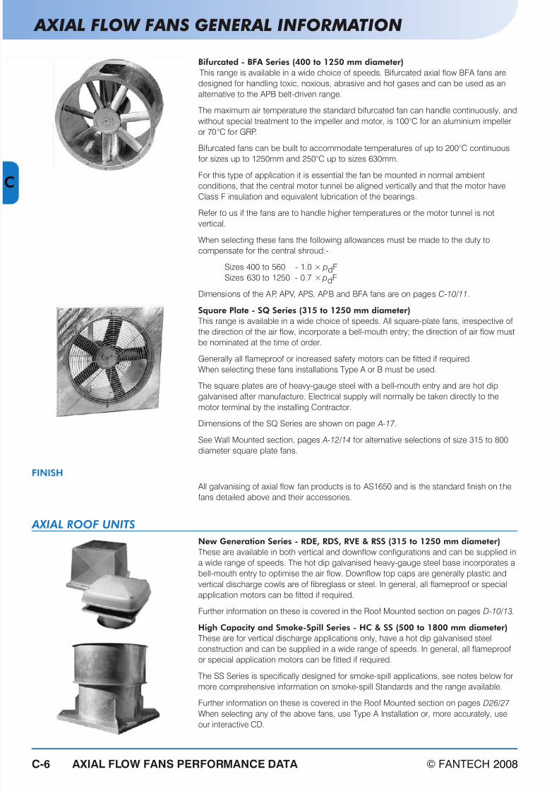
Bifurcated - BFA Series (400 to 1250 mm diameter)
This range is available in a wide choice of speeds. Bifurcated axial flow BFA fans are
designed for handling toxic, noxious, abrasive and hot gases and can be used as an
alternative to the APB belt-driven range.
The maximum air temperature the standard bifurcated fan can handle continuously, and
without special treatment to the impeller and motor, is 100°C for an aluminium impeller
or 70°C for GRP.
Bifurcated fans can be built to accommodate temperatures of up to 200°C continuous
for sizes up to 1250mm and 250°C up to sizes 630mm.
For this type of application it is essential the fan be mounted in normal ambient
conditions, that the central motor tunnel be aligned vertically and that the motor have
Class F insulation and equivalent lubrication of the bearings.
Refer to us if the fans are to handle higher temperatures or the motor tunnel is not
vertical.
When selecting these fans the following allowances must be made to the duty to
compensate for the central shroud:-
Sizes 400 to 560 - 1.0 × pdF
Sizes 630 to 1250 - 0.7 × pdF
Dimensions of the AP, APV, APS, APB and BFA fans are on pages C-10/11.
Square Plate - SQ Series (315 to 1250 mm diameter)
This range is available in a wide choice of speeds. All square-plate fans, irrespective of
the direction of the air flow, incorporate a bell-mouth entry; the direction of air flow must
be nominated at the time of order.
Generally all flameproof or increased safety motors can be fitted if required.
When selecting these fans installations Type A or B must be used.
The square plates are of heavy-gauge steel with a bell-mouth entry and are hot dip
galvanised after manufacture. Electrical supply will normally be taken directly to the
motor terminal by the installing Contractor.
Dimensions of the SQ Series are shown on page A-17.
See Wall Mounted section, pages A-12/14 for alternative selections of size 315 to 800
diameter square plate fans.
FINISH
All galvanising of axial flow fan products is to AS1650 and is the standard finish on the
fans detailed above and their accessories.
AXIAL ROOF UNITS
New Generation Series - RDE, RDS, RVE & RSS (315 to 1250 mm diameter)
These are available in both vertical and downflow configurations and can be supplied ina wide range of speeds. The hot dip galvanised heavy-gauge steel base incorporates a
bell-mouth entry to optimise the air flow. Downflow top caps are generally plastic and
vertical discharge cowls are of fibreglass or steel. In general, all flameproof or special
application motors can be fitted if required.
Further information on these is covered in the Roof Mounted section on pages D-10/13.
High Capacity and Smoke-Spill Series - HC & SS (500 to 1800 mm diameter)
These are for vertical discharge applications only, have a hot dip galvanised steel
construction and can be supplied in a wide range of speeds. In general, all flameproof
or special application motors can be fitted if required.
The SS Series is specifically designed for smoke-spill applications, see notes below for
more comprehensive information on smoke-spill Standards and the range available.
Further information on these is covered in the Roof Mounted section on pages D26/27
When selecting any of the above fans, use Type A Installation or, more accurately, use
our interactive CD.

7/21/2019 SectionC_General.pdf
http://slidepdf.com/reader/full/sectioncgeneralpdf 6/8© FANTECH 2008 C-7AXIAL FLOW FANS PERFORMANCE DATA
AXIAL FLOW FANS GENERAL INFORMATION
C
SMOKE-SPILL APPLICATIONS
Smoke-spill fans have to be tested to Standard AS4429:1999 to conform with the new
requirements of AS/NZS1668.1:1998. To meet the Standards Fantech conducted an
extensive series of tests covering both air flow and temperature. The air flow tests for
sizes 315mm to 1000mm diameter conformed to BS848:Part 1, 1980 and to ISO5801
for sizes 1.0m to 2.0m. The temperature tests were conducted in accordance with
AS4429:1999, although the 300°C tests were extended from 0.5 hours to 2 hours to
ensure we met the needs of most of our export markets.
The outcome of the series of tests is that we can supply fans ranging in diameter from
315mm to 2000mm at speeds as high as 2 pole depending on size and, for both 50
and 60Hz supply that fully comply with the Standards in all respects.
The following conditions can be met:-
Discharge damper fail-open latching
An additional requirement of the Standards relates to the function of the discharge
dampers in unsprinklered buildings. Fantech has met the requirements with two
designs, the first being a manual release type requiring manual closing after the fan hasbeen run. These may be used for dedicated smoke spill fans. The second design, an
electro-mechanical arrangement, permits the shutters to close automatically after the
fan stops. These are recommended for use on dual-purpose ventilation/smoke-spill
fans. Fantech has provisional patents for both designs.
For advice on Smoke-Spill wiring requirements, refer to the above Standard.
Contact our Sales Engineers for additional information.
COMPUTER SELECTION
Our CD is an interactive product selection program encompassing the following features:-
a fan selection program an attenuator selection program an acoustic analysis system a project schedule builder enables drawings to be downloaded through dwg/dxf files and easily updated with the latest data from our website.
To obtain a copy of our CD contact one of our Sales Offices.
OPERATING SPEEDS AND TEMPERATURES
Impellers installed for O.E.M. applications are submitted to the vibration, cyclic torques
and temperature cycles that prevail within the item of equipment. It can therefore be
misleading to state maximum conditions unless the full operating environment isknown, as all the above points can be inter-related.
The table below should be used as a guide only. For accurate figures use our CD.
* Up to 1000mm diameter ** Applicable to 20°C *** 1400 Series only# 1400 Series = 800mm to 1400mm; 2000 Series = 1250mm to 2000mm
Blade Material Temperature Range Limiting Tip Speed**
Elta 1000 Impeller*
Aluminium -40°C to +200°C 115m/s
GRP -40°C to +70°C 95m/s
Nylon -40°C to +100°C 115m/s
Anti-static GRP -40°C to +70°C 95m/s
Elta 1400 & 2000 Impellers#
Aluminium -40°C to +200°C 105m/sGRP -40°C to +70°C 95m/s
Anti-static GRP*** -40°C to +70°C 95m/s
200ºC for two hours 200ºC for four hours 250ºC for four hours
280ºC for 0.5 hours 300ºC for 0.5 hours 300ºC for two hours

7/21/2019 SectionC_General.pdf
http://slidepdf.com/reader/full/sectioncgeneralpdf 7/8AXIAL FLOW FANS PERFORMANCE DATA
AXIAL FLOW FANS GENERAL INFORMATION
C-8 © FANTECH 2008
SOUND DATA
The performance curves on pages C-11/109 show the total in-duct sound power levels
for the outlet side of the fan. Intermediate values may be obtained by interpolation; the
data is based upon tests to BS848:Part 2, 1985.
More detailed information may be obtained by referring to the Sound Data table
applicable to the particular fan.
To use the table:-
1. The performance zone applicable to the fan duty is obtained from the large
background numbering on the performance graph.
2. The correction values are then read from the relevant zone in the Sound Data table.
The total and octave band sound power levels for inlet and outlet side, in-duct and
free field, are obtained by adding or subtracting the applicable values from the total
sound power level obtained from the performance curve.
3. Total sound pressure levels at 3m and spherical radiation (re 20mPa) are obtained
by subtracting 21dB from the applicable sound power levels
4. The “A” weighted sound pressure (dB(A)) is obtained by subtracting the dB(A) value
listed in the table from the total sound pressure.

7/21/2019 SectionC_General.pdf
http://slidepdf.com/reader/full/sectioncgeneralpdf 8/8© FANTECH 2008 C-9AXIAL FLOW FANS PERFORMANCE DATA
EXAMPLE
C
A 630mm axial flow fan (AP Series) running at 24 rev/sec, Type D
installation (fully ducted) to give a duty of 3.5m 3 /s at 180 Pa
static pressure.
1 Air flow 3.5m3 /s
2 Static pressure is 180 Pa; no correction is required as thecurves are plotted for Type D installation.
3 Blade angle setting = 25°
Full impeller code = 0634/10/25°
4 Fan impeller power, PR = 1.30 kW
Recommended motor power = 1.5 kW
Motor frame size is D90L
See pages N-3/4 for details of these motors.
5 Fan total efficiency
where:qv = volume flow, m3 /s
ptF = fan total pressure, Pa
= psF + pdF
PR = fan impeller power, kW
6 Outlet side in-duct sound power level, Lw= 90 dB (by
interpolation)
7 Relevant sound zone 5
8 From the sound data table using zone 5 inlet side in-duct
data
9 Total sound power level correction value for fan inlet= 0dB
Hence total sound power, Lw = 90dB
10 Octave band spectra correction values
*Correction values are negative unless shown otherwise and
are subtracted from the Total Sound Power.
Correction value to Sound Pressure at 3m is 21dB, (see Ref.
i and Fig. 7 on page H-32) therefore:
Total sound pressure level Lp at 3m = 90 - 21 = 69dB.
Octave band spectra correction values as for step 10 at 3m:
11 Correction value from dB at 3m to dB(A) at 3m = -3
Total dB(A) level at 3m = 69 - 3 = 66dBA. Similar sound
data could have been deduced for the outlet side in-duct or
inlet and outlet free field levels from the data shown in the
Sound Data table.
Hz 63 125 250 500 1k 2k 4k 8k
* 6 15 8 9 7 10 11 19
LwdB 84 75 82 81 83 80 79 71
Hz 63 125 250 500 1k 2k 4k 8k
LpdB 63 55 61 60 62 59 58 50
31
4
7 98
5 6
2 P F d
7
Blade angle 40o
10o
35o
30o
25o
20o
15o
0
1201008060402010
1008060402010
1201008060402010
1.0 2.0 3.0 6.05.04.0 7.0
0Tested with motor downstream of impeller Density 1.2 kg/m
3
2.0
1.0
3.0
40
80
120
240
400
360
320
280
200
160
p
S F
- F a n
s t a t i c
p r e s s u r e
, P
a
qV-Volume flow, m /s
3
Relative pressure loss, Pa
Type A V
V
V
Type B
Type C
P R - F
a n
i m p e l l e r
p o w e r ,
k W
40o
10o
35o
30o
25o
20o
15o
0
92
93
93
93
91
93
dBW
92
90
92
91
89
91
91
89
91
91
91
92
0634/10150 Hub
7
2
13
4
6
1 3
12
1.30 69%
11 Cont.
12 If a selection for the same fan and duty had been required
for a Type A installation, then the static pressure would have
to be corrected as follows.
Relative pressure loss = +35 Pa
13 Revised static pressure for curve selection purposes
= 180 + 35
= 215 Pa.
This would result in a fan selection at 27°, an impeller power
of 1.54kW, an outlet side in-duct total noise level of 91dB
and the duty point moving into zone 2.
SELECTION PROCEDURE
31710107981691Inlet
21612107861460Outlet
31911107981560Inlet
325169651115140Outlet
424191586317122Inlet52013109981170Outlet
02010864719180Inlet
11711765917140Outlet
22614106492017+2Inlet
429181384814160Outlet
432241792162527+1Inlet
dBA8k4k2k1k50025012563TotalZone
In-Duct
dB
1
2
34
5
6
In-Duct Spectrum Corrections, dB
8 9 10 11


