Embed Size (px)
Citation preview
DESIGNERS
ND DEPARTMENT OF TRANSPORTATION
__________________________________________
APPROVED DATE _________________________
WILLISTONMINOT
DICKINSON
BISMARCK
LAKE
DEVILS
CITY
VALLEY
FORKS
GRAND
FARGO
C A S S
7
5
4 3
1M O R T O N
2 8
F O R K S
G R A N D
6
D I V I D E
W I L L I A M S
B U R K E
M O U N T R A I L
R E N V I L L E
W A R D
B O T T I N E A U
M C H E N R Y
M C L E A N
M E R C E R
D U N N
M C K E N Z I E
B I L L I N G S
G O L D E N V A L L E Y
S L O P E
B O W M A N A D A M S
H E T T I N G E R
S T A R K
G R A N T
S I O U X
O L I V E R
E M M O N S
B U R L E I G H
M C I N T O S H
L O G A N
K I D D E R
S H E R I D A N
P I E R C E
R O L E T T E
T O W N E R
B E N S O N
W E L L S
S T U T S M A N
L A M O U R E
D I C K E Y
B A R N E S
G R I G G S
F O S T E R
E D D Y
R A M S E Y
C A V A L I E RP E M B I N A
W A L S H
N E L S O N
S T E E L E
T R A I L L
R A N S O M
S A R G E N T
R I C H L A N D
Fargo District
Lyle Landstrom/s/
Bob Walton /s/
12/29/17
GRAND
FORKS
GO
LD
EN
VA
LLE
Y
CASS
RIC
HLA
ND
RANSOM
SARGENTDICKEY
LA MOURE
BARNES
KIDDER
LOGAN
MC IN
TOSH
BU
RLEIG
H
MORTON
GRANT
SIOUXADAMS
HETTINGER
SLOPE
BOWMAN EM
MO
NS
OLIVER
MERCER
STARKBIL
LIN
GS
DUNN
MC KENZIE
MC LEAN
SHERID
AN
WELLS
EDDY
FOSTER
GRIG
GS
STEELE
TRAILL
DIVIDE
WILLIAMS
BURKE
MO
UNTR
AIL
RE
NVIL
LE
WARD
MC H
EN
RY
BOTTINEAU
ROLLE
TTE
TO
WNER
CAVALIER
RA
MSEY
WALSH
PE
MBIN
A
NELS
ONBENSONP
IER
CE
STUTSMAN
STATE COUNTY MAP
STATE PROJECT NO.
ND
PCNNO.
SHEET
NO.
SECTION
DEPARTMENT OF TRANSPORTATION
NORTH DAKOTA
__________________________________________
APPROVED DATE _________________________
engineer under the laws of the state of ND.
and that I am a duly registered professional
prepared by me or under my direct supervision
I hereby certify that the attached plans were
12/29/2017 llandstr G:\PROJECT\District Striping\2018\001TS_001_TitleSheet.dgn11:17:38 AM
of Transportation
North Dakota Department
document is stored at the
on and the original
PE- ,
Registration Number
issued and sealed by
This document was originally
JOB #
GROSS MILES NET MILES PROJECT NUMBER \ DESCRIPTION
effective on the date the project is advertised.
Department of Transportation and the Supplemental Specifications
2014 Standard Specifications adopted by the North Dakota
GOVERNING SPECIFICATIONS:
11HES-8-999(039)
12/29/17
22027
HES-8-999(039)
Traill, Cass, Ransom, Richland, and Sargent Counties
Pavement Marking
NDDOT Fargo District
HES-8-999(039)
Lyle Landstrom/s/
4079
Lyle landstrom /s/
12/29/17
44

STATE PROJECT NO.SECTION
NO.SHEET
NO.
12/28/2017 9:36:47 AM llandstr
ND 2HES-8-999(039)TABLE OF CONTENTS 1
.. .. ....
Section Page(s) Description
PLAN SECTIONS
1 Title Sheet1
2 Table of Contents1
4 Scope of Work1
6 Notes1
8 Quantities1
11 Data Tables1 - 3
120 Pavement Marking1 - 7
Number Description
LIST OF STANDARD DRAWINGS
NDDOT AbbreviationsD-101-1
NDDOT AbbreviationsD-101-2
NDDOT AbbreviationsD-101-3
Line StylesD-101-20
Line StylesD-101-21
SymbolsD-101-30
SymbolsD-101-31
SymbolsD-101-32
Breakaway Systems For Construction Zone Signs - Perforated TubeD-704-7
Breakaway Systems For Construction Zone Signs - U-Channel PostD-704-8
Construction Sign Details - Terminal And Guide SignsD-704-9
Construction Sign Details - Regulatory SignsD-704-10
Construction Sign Details - Warning SignsD-704-11
Construction Sign Punching And Mounting DetailsD-704-14
Road Closure LayoutsD-704-15
Lane Closures On Urban Streets LayoutsD-704-25
Traffic Control Plan For Moving OperationsD-704-27
Pavement Marking Message DetailsD-762-1
Interstate Pavement Marking 4 Lane Divided HighwayD-762-2
Pavement MarkingD-762-4
Pavement Marking for Standard 90 Degree Flared Intersection-(No Center Left Turn Lane on Major Road)D-762-5
Pavement Marking for Standard 90 Degree Flared Intersection-(Center Left turn Lane on Major Road)D-762-6
Number Description
SPECIAL PROVISIONS
SP 595(14) Polyurea Pavement markings (PPM)Polyurea Pavement Markings (PPM)
T R
A I
L L
LIS
BO
N
FO
RM
AN
EL
LIO
TT
FO
RT
RA
NS
OM
EN
DE
RL
IN
SH
EL
DO
N
GW
INN
ER
MIL
NO
R
CO
GS
WE
LL
CA
YU
GA
RU
TL
AN
D
HA
VA
NN
A
CH
RIS
TIN
E
WA
LC
OT
T
CO
LF
AX
AB
ER
CR
OM
BIE
DW
IGH
T
MO
OR
ET
ON
BA
RN
EY
WY
ND
ME
RE
MA
NT
AD
OR
GR
EA
T B
EN
D
FA
IRM
OU
NT
PA
GE
AY
R
BU
FF
AL
O
CIT
Y
TO
WE
R
AL
ICE
LE
ON
AR
DK
IND
RE
D
DA
VE
NP
OR
T
HO
RA
CE
CA
SS
EL
TO
N
MA
PL
ET
ON
GR
AN
DIN
GA
RD
NE
R
HU
NT
ER
AR
TH
UR
AM
EN
IA
HA
RW
OO
D
CL
IFF
OR
D
GA
LE
SB
UR
G
PO
RT
LA
ND
MA
YV
ILL
E
BU
XT
ON
HA
TT
ON
R I
C H
L A
N D
R A
N
S
O
M
S A
R G
E N
T
T R
A I
L L
HIC
KS
ON
HIL
LS
BO
RO
FA
RG
O
WA
HP
ET
ON
WE
ST
FA
RG
O
C A
S S
81
10
10
LID
GE
RW
OO
D
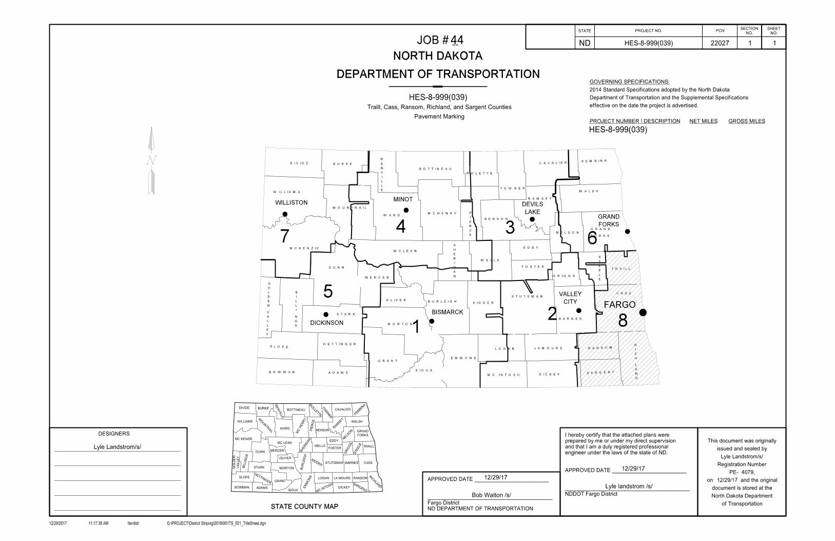
Work Areas
15
FA
RG
O D
IS
TR
IC
T
ND
DO
T
Omit for construction
Ap
pro
x R
P 7
5.5
to
RP
76
Coordinate with construction
STATE PROJECT NO.
ND
NO.
SHEET
NO.
SECTION
12/29/2017 llandstr G:\PROJECT\District Striping\2018\004SW _001_SCOPE.dgn11:21:46 AM
of Transportation
North Dakota Department
document is stored at the
on and the original
PE- ,
Registration Number
issued and sealed by
This document was originally
4 1
Scope of W ork
HES-8-999(039)
4079
12/29/2017
Lyle landstrom /s/
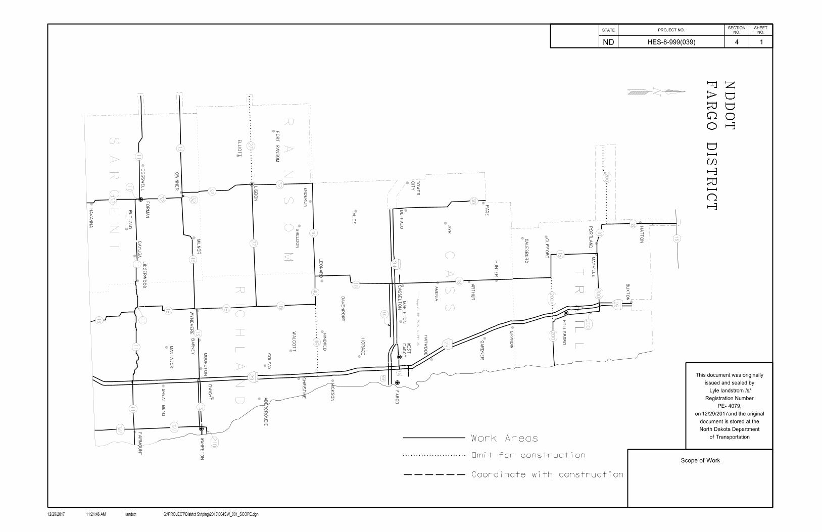
work. Segments may be removed or added pending additional projects being bid or not being bid
Engineer or Assistant Disrtict Engineer to assure that segments of highways are cleared for
100-P01 COORDINATION: At least one week before beginning work, contact the District
used.
that are found during the course of this project. It is anticipated that additional quantities will be
all of them prior to the construction season. The intent is to remark any worn pavement markings
Although the plans have identified specific locations to be remarked, it is difficult to determine
762-PO3 REPLACEMENT OF PAVEMENT MARKINGS NOT IDENTIFIED IN THE PLANS
existing markings in the contract unit prices for grooved markings.
complete, remove the portion that remains. Include the cost of removing
If portions of the existing marking remain in place after grooving is
762-P01 PREFORMED PATTERNED PAVEMENT MARKING - GROOVED:
If wider markings are installed, the length will be multiplied by the width and divided by 4.
Installation based on a 4 inch wide line, one mile long.
meet the requirements of Section 762.03 "Materials". The Engineer will measure Pavement Marking
Section 762.04 C.2, "Water Based Paint". Use water based pavement marking paint materials that
762-P02 PAVEMENT MARKING INSTALLATION: Install water based pavement markings as specified in
STATE PROJECT NO.
ND
NO.
SHEET
NO.
SECTION
12/29/2017 llandstr G:\PROJECT\District Striping\2018\006NT_001_Notes.dgn11:47:27 AM
of Transportation
North Dakota Department
document is stored at the
on and the original
PE- ,
Registration Number
issued and sealed by
This document was originally
4079
1
Plan Notes
12/29/2017
HES-8-999(039)
Lyle Landstrom /s/
6
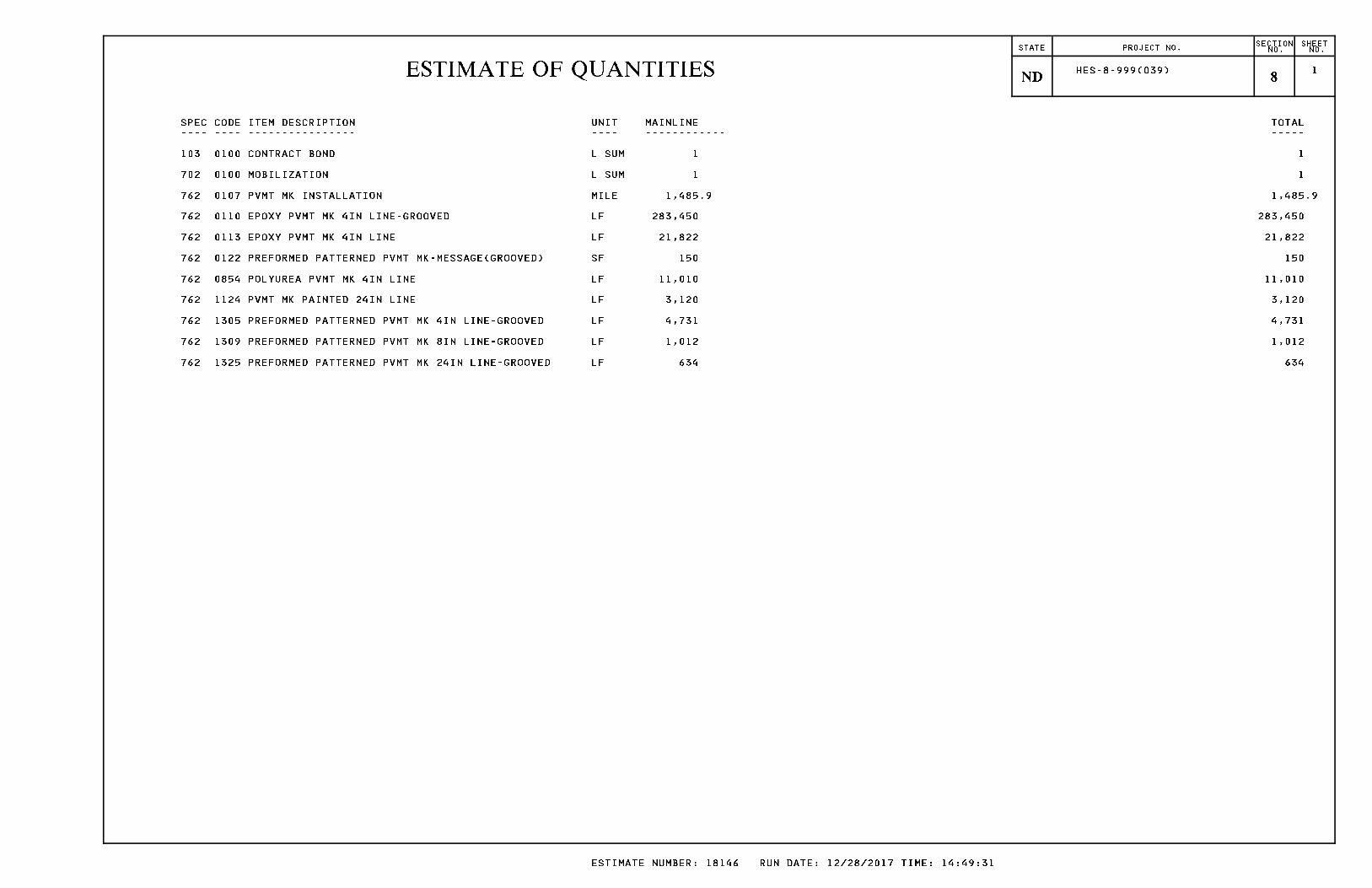
ESTIMATE OF QUANTITIESSTATE PROJECT NO. SECTION
NO.SHEETNO.
ND 8 HES-8-999(039) 1
SPEC CODE ITEM DESCRIPTION UNIT MAINLINE TOTAL---- ---- ---------------- ---- ------------ -----
103 0100 CONTRACT BOND L SUM 1 1
702 0100 MOBILIZATION L SUM 1 1
762 0107 PVMT MK INSTALLATION MILE 1,485.9 1,485.9
762 0110 EPOXY PVMT MK 4IN LINE-GROOVED LF 283,450 283,450
762 0113 EPOXY PVMT MK 4IN LINE LF 21,822 21,822
762 0122 PREFORMED PATTERNED PVMT MK-MESSAGE(GROOVED) SF 150 150
762 0854 POLYUREA PVMT MK 4IN LINE LF 11,010 11,010
762 1124 PVMT MK PAINTED 24IN LINE LF 3,120 3,120
762 1305 PREFORMED PATTERNED PVMT MK 4IN LINE-GROOVED LF 4,731 4,731
762 1309 PREFORMED PATTERNED PVMT MK 8IN LINE-GROOVED LF 1,012 1,012
762 1325 PREFORMED PATTERNED PVMT MK 24IN LINE-GROOVED LF 634 634
ESTIMATE NUMBER: 18146 RUN DATE: 12/28/2017 TIME: 14:49:31
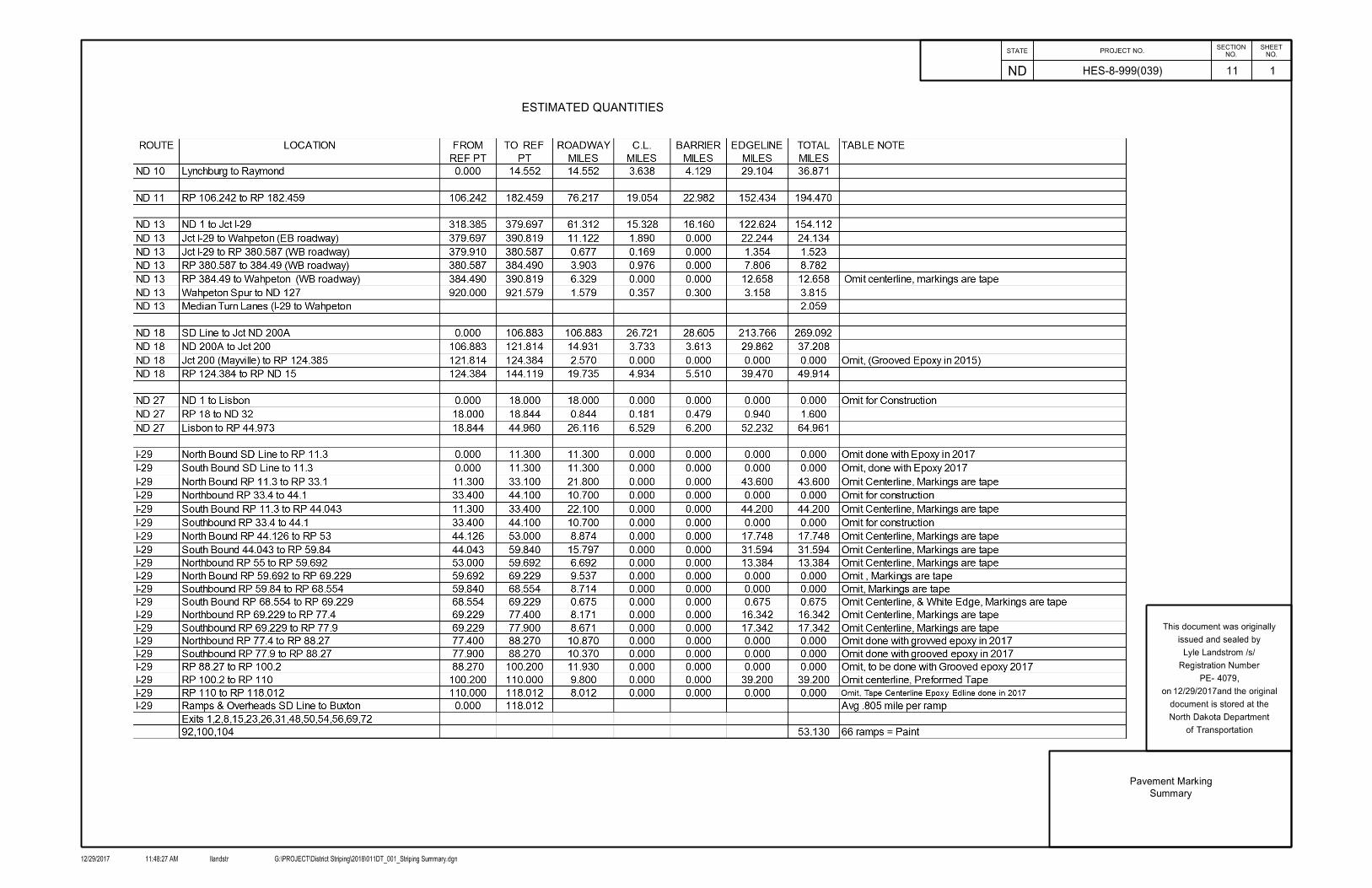
ESTIMATED QUANTITIES
STATE PROJECT NO.
ND
NO.
SHEET
NO.
SECTION
12/29/2017 llandstr G:\PROJECT\District Striping\2018\011DT_001_Striping Summary.dgn11:48:27 AM
of Transportation
North Dakota Department
document is stored at the
on and the original
PE- ,
Registration Number
issued and sealed by
This document was originally
4079
11
1
Pavement Marking
Summary
HES-8-999(039)
Lyle Landstrom /s/
12/29/2017

ESTIMATED QUANTITIES
Paint Rural Interchanges
52 Rural Interstate ramps x 60 LF = 3120 LF.
24 In Stop Bars:
338 Westbound, 340 WestboundI-94 Exits: 314, 317, 320, 322, 324, 328, 331 Westbound,
79 Northbound, 86 Northbound, 92, 100, 104, 111, 118
I-29 Exits: 1, 2, 8,15, 23, 26, 31, 37, 42, 56, 69, 72,
STATE PROJECT NO.
ND
NO.
SHEET
NO.
SECTION
12/29/2017 llandstr G:\PROJECT\District Striping\2018\011DT_002_Striping Summary.dgn12:31:10 PM
of Transportation
North Dakota Department
document is stored at the
on and the original
PE- ,
Registration Number
issued and sealed by
This document was originally
4079
11
2
Pavement Marking
Summary
HES-8-999(039)
Lyle Landstrom /s/
12/29/2017

I-29 GENERAL REPLACEMENT - GROVVED EPOXY
I-29 WHITE CENTERLINE SKIPSPREFORMED PATTERN PAVEMENT MARKING
LOCATIONS NOT SHOWN ON PLAN SHEETSPREFORMED PATTERN PAVEMENT MARKING - GROOVED
TRUCK PARKING AND WEIGH STATION AREASEPOXY PAVEMENT MARKING 4 IN LINE
STATE PROJECT NO.
ND
NO.
SHEET
NO.
SECTION
12/29/2017 llandstr G:\PROJECT\District Striping\2018\011DT_003_Pvmt Mk and Epoxy Summary.dgn12:31:43 PM
of Transportation
North Dakota Department
document is stored at the
on and the original
PE- ,
Registration Number
issued and sealed by
This document was originally
4079
11
3
Preformed, Epoxy, MME
Quantities
Pavement Markings
HES-8-999(039)
Lyle Landstrom /s/
12/29/2017
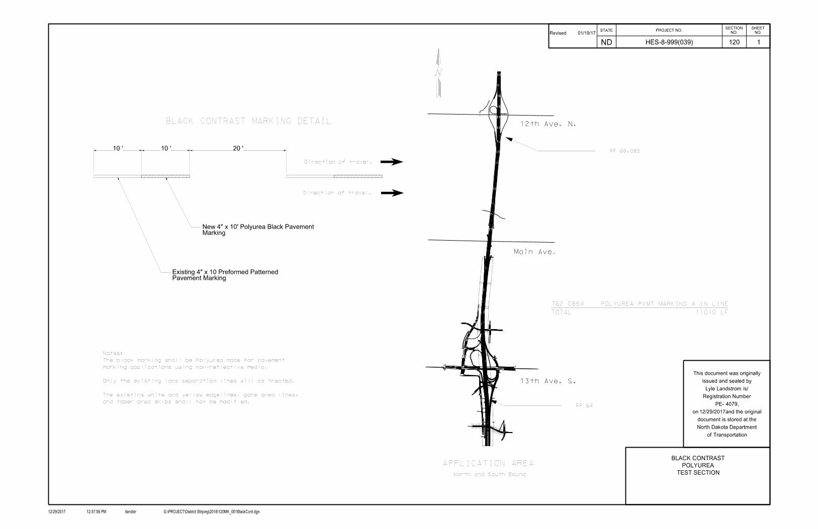
13th Ave. S.
Main Ave.
Sta 3439+00
End Project
Signal
End ProjectSta 3439+00
Sheet
Piling
Sheet
Piling
Sheet
Piling
12th Ave. N.
20 ’10 ’10 ’
Pavement MarkingExisting 4" x 10 Preformed Patterned
RP 66.085
RP 64
APPLICATION AREA
North and South Bound
Direction of travel.
Direction of travel.
and taper area skips shall not be modified.
The existins white and yellow edgelines, gore area lines,
Only the existing lane separation lines will be treated.
marking applications using non-reflective media.
The black marking shall be Polyurea made for pavement
Notes:
BLACK CONTRAST MARKING DETAIL
MarkingNew 4" x 10’ Polyurea Black Pavement
TOTAL 11010 LF
762 0854 POLYUREA PVMT MARKING 4 IN LINE
STATE PROJECT NO.
ND
NO.
SHEET
NO.
SECTION
12/29/2017 llandstr G:\PROJECT\District Striping\2018\120MK_001BlackCont.dgn12:57:58 PM
of Transportation
North Dakota Department
document is stored at the
on and the original
PE- ,
Registration Number
issued and sealed by
This document was originally
4079
120
BLACK CONTRAST
TEST SECTION
1HES-8-999(039)
Lyle Landstrom /s/
Revised 01/19/17
POLYUREA
12/29/2017
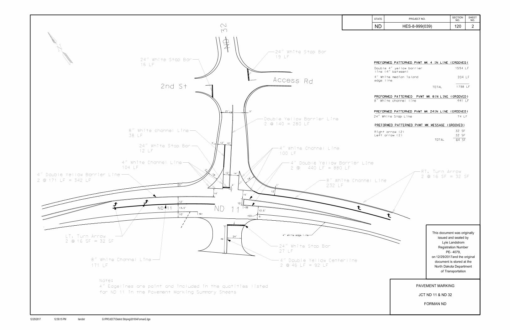
ND 11
ND 32
Access Rd
42’
ND 11
2nd St
10’
12’
13.5’
5’
+38
10’
+61
14’
4’
15’
12’ 14’
13.5’
9’
18’
12’
1’
18’
2’
12’ 12’
3’21’
24’
+63
46’
2’
4" white edge line
line (4" between)
Double 4" yellow barrier
TOTAL
TOTAL
8" White channel line
24" White Stop Line
edge line
4" White median island
19 LF
24" White Stop Bar
16 LF
24" White Stop Bar
2 @ 140 = 280 LF
Double Yellow Barrier Line
38 LF
8" White channel Line
12 LF
24" White Stop Bar
104 LF
4" White Channel Line
100 LF
4" White Channel Line
232 LF
8" White Channel Line 2 @ 16 SF = 32 SF
RT. Turn Arrow
2 @ 171 LF = 342 LF
4" Double Yellow Barrier Line
171 LF
8" White Channel Line
2 @ 16 SF = 32 SF
LT. Turn Arrow
27 LF
24" White Stop Bar
2 @ 46 LF = 92 LF
4" Double Yellow Centerline
2 @ 440 LF = 880 LF
4" Double Yellow Barrier LIne
1594 LF
204 LF
1798 LF
441 LF
74 LF
Right arrow (2)
Left arrow (2)
32 SF
32 SF
64 SF
for ND 11 in the Pavement Marking Summary Sheets
4" Edgelines are paint and included in the quatities listed
Note:
PREFORMED PATTERNED PVMT MK 4 IN LINE (GROOVED)
PREFORMED PATTERNED PVMT MK 8IN LINE (GROOVED)
PREFORMED PATTERNED PVMT MK 24IN LINE (GROOVED)
PREFORMED PATTERNED PVMT MK MESSAGE (GROOVED)
STATE PROJECT NO.
ND
NO.
SHEET
NO.
SECTION
12/29/2017 llandstr G:\PROJECT\District Striping\2018\AForman2.dgn12:59:15 PM
of Transportation
North Dakota Department
document is stored at the
on and the original
PE- ,
Registration Number
issued and sealed by
This document was originally
4079
HES-8-999(039) 120
PAVEMENT MARKING
JCT ND 11 & ND 32
FORMAN ND
2
Lyle Landstrom
12/29/2017

10:1 Taper
10:1 Taper
+67
+67
+20
47’
10:1 Taper
10:1 Taper
+20
47’
+34
+34
12’12’
12’
198’
199’
ND 11
ND 32
4" white edge line
4" white edge line
4" white edge line
4" white edge line
42 LF24" White Stop Bar
47 LF8" White Channel Line
for ND 11 in the Pavement Marking Summary sheet. 4" Centerline and Edgeline are included with the quantites listed Note:
PREFORMED PATTERNED PVMT MK 8IN LINE (GROOVED)
PREFORMED PATTERNED PVMT MK 24 IN LINE (GROOVED)
8" White Channel Line 47.0 LF
24" White Stop Line 42.0 LF
STATE PROJECT NO.
ND
NO.
SHEET
NO.
SECTION
12/29/2017 llandstr G:\PROJECT\District Striping\2018\FormanS.Jct32_&_11.dgn12:59:42 PM
of Transportation
North Dakota Department
document is stored at the
on and the original
PE- ,
Registration Number
issued and sealed by
This document was originally
4049
HES-8-999(039) 120
Pavement Marking
S. Jct ND 11 & ND 32
ND 11 RP 129.467
3
Lyle Landstrom
12/29/2017
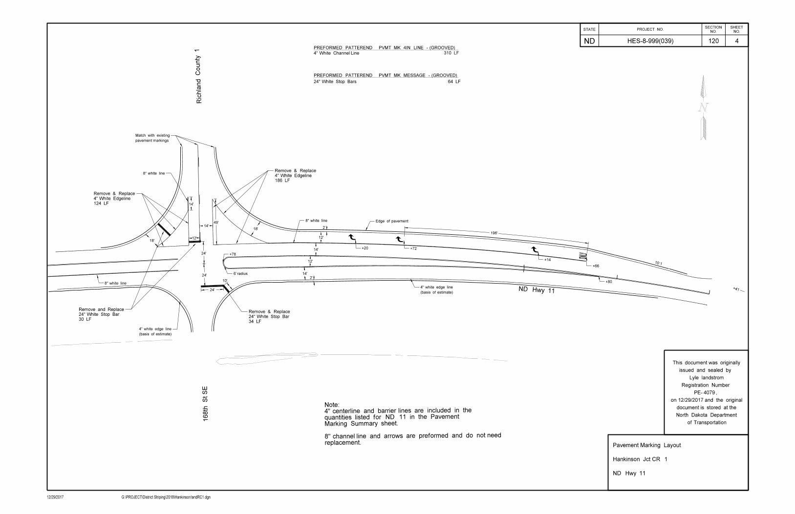
168th St S
E
ND Hwy 11
Richla
nd
County 1
24’
24’14’
12’
12’
14’
2’
2’
24’
12’
196’
18’
10’
18’14’
14’
49’
+41
6’ radius
Edge of pavement
+20 +72
+14
+66
+80
pavement markings
Match with existing
(basis of estimate)
4" white edge line
(basis of estimate)
4" white edge line
8" white line
8" white line
+78
8" white line
34 LF
24" White Stop Bar
Remove & Replace
186 LF
4" White Edgeline
Remove & Replace
124 LF
4" White Edgeline
Remove & Replace
30 LF
24" White Stop Bar
Remove and Replace
PREFORMED PATTEREND PVMT MK 4IN LINE - (GROOVED)
310 LF
PREFORMED PATTEREND PVMT MK MESSAGE - (GROOVED)
64 LF24" White Stop Bars
replacement. 8" channel line and arrows are preformed and do not need
Marking Summary sheet. quantities listed for ND 11 in the Pavement4" centerline and barrier lines are included in the Note:
4" White Channel Line
10:1
12/29/2017 G:\PROJECT\District Striping\2018\Hankinson!andRC1.dgn
STATE PROJECT NO.
ND
NO.
SHEET
NO.
SECTION
of Transportation
North Dakota Department
document is stored at the
on and the original
PE- ,
Registration Number
issued and sealed by
This document was originally
120 4
4079
HES-8-999(039)
Pavement Marking Layout
Hankinson Jct CR 1
ND Hwy 11
Lyle landstrom
12/29/2017

ND Hwy 11
12’
14’
12’
79’
24’
93rd St SE
2’
2’
12’
187.5’
fronta
ge road
18’14’
18’
14’
15’
48’
Edge of pavement
+65 +16+50
+02
4" double yellow barrier line
(basis of estimate)
4" white edge line
8" white line
158 LF
4" Double Yellow Centerline
15 LF
8" White Channel line
Remove & Replace
147 LF
4" White channel Lines
Remove & Replace
186 LF
4" White Channel Line
Remove and Replace
30 LF
24" Stop Bars
Remove & Replace
replacement. 8" channel line and arrows are preformed and do not need
Marking Summary sheet. quantities listed for ND 11 in the Pavement4" centerline and barrier lines are included in the Note:
PREFORMED PATTEREND PVMT MK 4IN LINE - (GROOVED)
333 LF
PREFORMED PATTEREND PVMT MK MESSAGE - (GROOVED)
30 LF24" White Stop Bars
4" White Channel Line
PREFORMED PATTEREND PVMT MK 8IN LINE - (GROOVED)
15 LF8" White Channel Line
158 LF4" Yellow Centerline
10:1
12/29/2017 G:\PROJECT\District Striping\2018\Hankinson3Turnlanes.dgn
STATE PROJECT NO.
ND
NO.
SHEET
NO.
SECTION
of Transportation
North Dakota Department
document is stored at the
on and the original
PE- ,
Registration Number
issued and sealed by
This document was originally
120
5
4079
HES-8-999(039)
Pavement Marking Layout
RP 166.715
ND Hwy 11
Lyle Landstrom
12/29/2017
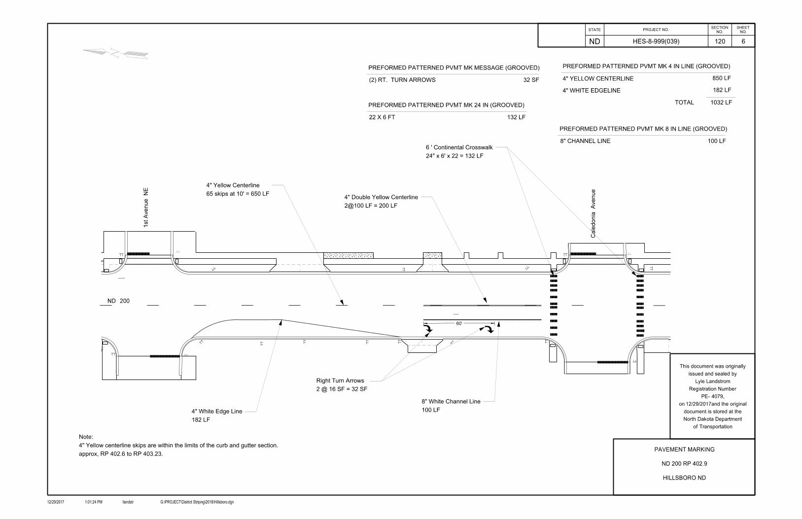
100 LF
8" White Channel Line
182 LF
4" White Edge Line
2 @ 16 SF = 32 SF
Right Turn Arrows
2@100 LF = 200 LF
4" Double Yellow Centerline
24" x 6’ x 22 = 132 LF
6 ’ Continental Crosswalk
65 skips at 10’ = 650 LF
4" Yellow Centerline
approx, RP 402.6 to RP 403.23.
4" Yellow centerline skips are within the limits of the curb and gutter section.
Note:
4" YELLOW CENTERLINE
4" WHITE EDGELINE
850 LF
182 LF
TOTAL 1032 LF
8" CHANNEL LINE 100 LF
32 SF(2) RT. TURN ARROWS
132 LF22 X 6 FT
PREFORMED PATTERNED PVMT MK 4 IN LINE (GROOVED)PREFORMED PATTERNED PVMT MK MESSAGE (GROOVED)
PREFORMED PATTERNED PVMT MK 8 IN LINE (GROOVED)
PREFORMED PATTERNED PVMT MK 24 IN (GROOVED)
60’
ND 200
1st
Avenue
NE
Cale
donia
Avenue
STATE PROJECT NO.
ND
NO.
SHEET
NO.
SECTION
12/29/2017 llandstr G:\PROJECT\District Striping\2018\Hillsboro.dgn1:01:24 PM
of Transportation
North Dakota Department
document is stored at the
on and the original
PE- ,
Registration Number
issued and sealed by
This document was originally
4079
HES-8-999(039) 120
PAVEMENT MARKING
ND 200 RP 402.9
HILLSBORO ND
6
Lyle Landstrom
12/29/2017

ONLY
ONLY
ONLY
X
X
X
X
X
X
X
X
X
X
X
X
X
X
X
X
X
X
X
PointReference East Bound
24’
330’
(Paint entire perimeter)4" white median island edge line
9’50’
60’
20’
32’
24’
Sec. Line
330’240’
150’
20:1
20:1
240’
4" white skip line10’
8’
30’
8’
46.7’ 8’ 44’ 8’
44’ 8’ 44’
14’
8’
14’
12’
Rt. Lt.
389.131
389.063
388.639
388.517
388.311
387.912
387.639
387.536
386.636
385.636
384.636
383.679
382.677
381.671
8" white channel line
section are paint and require repainting.not need replacement. The 8" right tiurn lanes on the asphaltsection are marked in Grooved preformed tape and doThe 8" Right Turn Lane Channel lines on the concrete Paint entire median perimeter.
Note:
X
X X
X
X
X
X
X
X
X
X
X
X
X
X
X
X
X
Turn Lane Locations
West Bound
RemarksRt. Lt.
Westbound is asphalt section
Paint 8" line on westbound asphalt section
Paint 8" line on westbound asphalt section
Total = 10,873 LF or 2.059 Miles
2 8" Channel lines x 362’ x 2 = 724 LF17 Lt. Turn Lanes x 597 ft = 10149 LFPavement Marking Painted 4IN Line
STATE PROJECT NO.
ND
NO.
SHEET
NO.
SECTION
12/29/2017 llandstr G:\PROJECT\District Striping\2018\120MK_013_ND13 EB Turn Lanes.dgn12:58:30 PM
of Transportation
North Dakota Department
document is stored at the
on and the original
PE- ,
Registration Number
issued and sealed by
This document was originally
4079
120
Pavement Marking
ND13
I-29 to Wahpeton
HES-8-999(039)
Lyle Landstrom /s/
7
12/29/2017
or `
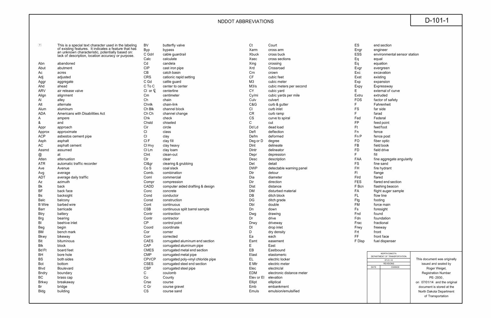
Abn abandoned
Abut abutment
Ac acres
Adj adjusted
Aggr aggregate
Ahd ahead
ARV valve releaseair
Align alignment
Al alley
Alt alternate
Alum aluminum
ADA Act Disabilities withAmericans
A ampere
& and
Appr approach
Approx approximate
ACP pipe cementasbestos
Asph asphalt
AC cementasphalt
Assmd assumed
@ at
Atten attenuation
ATR recorder trafficautomatic
Ave Avenue
Avg average
ADT traffic dailyaverage
Az azimuth
Bk back
BF faceback
Bs backsight
Balc balcony
WireB wirebarbed
Barr barricade
Btry battery
Brg bearing
BI inletbeehive
Beg begin
BM markbench
Bkwy bikeway
Bit bituminous
Blk block
FtBd feetboard
BH holebore
BS sidesboth
Bot bottom
Blvd Boulevard
Bndry boundary
BC capbrass
Brkwy breakaway
Br bridge
Bldg building
BV valvebutterfly
Byp bypass
GdrlC guardrailcable
Calc calculate
Cd candela
CIP pipe ironcast
CB basincatch
CRS setting rapidcationic
GdC guardcattle
C ToC center tocenter
Cl centerline
Cm centimeter
Ch chain
Chnlk chain-link
BlkCh blockchannel
ChCh changechannel
Chk check
Chsld chiseled
Cir circle
Cl class
Cl clay
FCl fillclay
HvyCl heavyclay
LmCl loamclay
Clnt clean-out
Clr clear
Cl&gr grubbing &clearing
SCo slackcoal
Comb. combination
Coml commercial
Compr compression
CADD design & drafting aidedcomputer
Conc concrete
Cond conductor
Const construction
Cont continuous
CSB sample barrel splitcontinuous
Contr contraction
Contr contractor
CP pointcontrol
Coord coordinate
Cor corner
Corr corrected
CAES section end aluminumcorrugated
CAP pipe aluminumcorrugated
CMES section end metalcorrugated
CMP pipe metalcorrugated
CPVCP pipe chloride poly-vinylcorrugated
CSES section end steelcorrugated
CSP pipe steelcorrugated
C coulomb
Co County
Crse course
GrC gravelcourse
CS sandcourse
Ct Court
Xarm armcross
Xbuck buckcross
Xsec sectionscross
Xing crossing
Xrd Crossroad
Crn crown
CF feetcubic
M3 metercubic
M3/s second per meterscubic
CY yardcubic
Cy/mi mile per yardscubic
Culv culvert
C&G gutter &curb
CI inletcurb
CR rampcurb
CS spiral tocurve
C cut
LdDd loaddead
Defl deflection
Defm deformed
D orDeg degree
Dlnt delineate
Dlntr delineator
Depr depression
Desc description
Det detail
DWP panel warningdetectable
Dtr detour
Dia diameter
Dir direction
Dist distance
DM materialdisturbed
DB blockditch
DG gradeditch
Dbl double
Dn down
Dwg drawing
Dr drive
Drwy driveway
DI inletdrop
D densitydry
Ea each
Esmt easement
E East
EB Eastbound
Elast elastomeric
EL lockerelectric
MtrE meterelectric
Elec electric/al
EDM meter distanceelectronic
El orElev elevation
Ellipt elliptical
Emb embankment
Emuls emulsion/emulsified
ES sectionend
Engr engineer
ESS station sensorenvironmental
Eq equal
Eq equation
Evgr evergreen
Exc excavation
Exst existing
Exp expansion
Expy Expressway
E curve ofexternal
Extru extruded
FOS safety offactor
F Fahrenheit
FS sidefar
F farad
Fed Federal
FP pointfeed
Ft feet/foot
Fn fence
PFn postfence
FO opticfiber
FB bookfield
FD drivefield
F fill
FAA angularity aggregatefine
FS sandfine
FH hydrantfire
Fl flange
Flrd flared
FES section endflared
BcnF beaconflashing
FA sample augerflight
FL lineflow
Ftg footing
FM mainforce
Fs foresight
Fnd found
Fdn foundation
Frac fractional
Frwy freeway
Frt front
FF facefront
DispF dispenserfuel
Ð
lack of description, location accuracy or purpose. an unknown characteristic, potentially based on: of existing features. It indicates a feature that has This is a special text character used in the labeling
REVISIONS
DATE CHANGE
DEPARTMENT OF TRANSPORTATION
NORTH DAKOTA
of Transportation
North Dakota Department
document is stored at the
on and the original
PE- ,
Registration Number
issued and sealed by
This document was originally
NDDOT ABBREVIATIONS D-101-1
07-01-14
2930
Roger Weigel,
07/01/14

FFP pipes fillerfuel
FLS sensor leakfuel
Furn furnish/ed
Gal gallon
Galv galvanized
Gar garage
LGs linegas
RegG regulator linegas
GMV valve maingas
MtrG metergas
GSV valve servicegas
GVP pipe ventgas
GV valvegate
Ga gauge
Geod geodetic
GIS System InformationGeographical
G giga
GPS System PositioningGlobal
Gov government
Grd graded/grade
Gr gravel
Grnd ground
GWM monitor waterground
Gdrl guardrail
Gtr gutter
PlgH pilingH
Hdwl headwall
Ha hectare
Ht height
HI instrument ofheight
Hel helical
H henry
Hz hertz
HDPE polyethylene densityhigh
HM masthigh
HP pressurehigh
HPS sodium pressurehigh
Hwy highway
Hor horizontal
HBP pavement bituminoushot
Hr hour(s)
Hyd hydrant
Ph content ionhydrogen
Id identification
" orIn inch
Incl tubeinclinometer
IMH manholeinlet
ID diameterinside
Inst instrument
Intchg interchange
Intmdt intermediate
Intscn intersection
Inv invert
IM monumentiron
PnI PinIron
IP Pipeiron
Jt joint
J joule
Jct junction
K kelvin
Kn newtonkilo
Kpa pascalkilo
Kg kilogram
Kg/m3 meter cubic perkilogram
Km kilometer
K Kip(s)
LS (licensed) SurveyorLand
LSIT Training In SurveyorLand
Ln lane
Lg large
Lat latitude
Lt left
L curve oflength
Lens lenses
Lvl level
LB booklevel
Lvlng leveling
Lht light
LP polelight
Ltg lighting
CoLig coallignite
SlLig slacklignite
LF footlinear
Liq liquid
LL limitliquid
L litre
Lm loam
Loc location
LC chordlong
Long. longitude
Lp loop
LD detectorloop
Lm lumen
Lum luminaire
SumL sumlump
Lx lux
ML linemain
HrM hourman
MH manhole
Mkd marked
Mkr marker
Mkg marking
MA armmast
Matl material
Max maximum
MC cornermeander
Meas measure
Mdn median
MD drainmedian
MC curingmedium
M mega
Mer meridian
M meter
M/s second permeters
M curve of ordinatemid
Mi mile
MM markermile
MP postmile
Ml milliliter
Mm millimeter
Mm/hr hour permillimeters
Min minimum
Misc miscellaneous
Mon monument
Mnd mound
Mtbl mountable
Mtd mounted
Mtg mounting
Mk muck
Mun municipal
N nano
NGS Survey GeodeticNational
NS sidenear
Neop neoprene
Ntwk network
N newton
N North
NE EastNorth
NW WestNorth
NB Northbound
# orNo. number
Obsc obscure(d)
Obsn observation
Ocpd occupied
Ocpy occupy
LocOff locationoffice
O/s offset
OC centeron
C consolidation dimensionalone
OC contentorganic
Orig original
O ToO out toout
OD diameteroutside
OH overhead
PMT transformer mountedpad
Pg pages
Pntd painted
Pr pair
Pnl panel
Pk park
PK nailParker-Kalon
Pa pascal
PSD distance sightpassing
Pvmt pavement
Ped pedestal
Ped pedestrian
PPP post pushbuttonpedestrian
Pen. penetration
Perf perforated
Per. perimeter
PL pipeline
Pl place
P&P profile &plan
PL limitplastic
Pl plate
Pt point
PCC curve compound ofpoint
PC curve ofpoint
PI intersection ofpoint
PRC curvature reverse ofpoint
PT tangent ofpoint
POC curve onpoint
POT tangent onpoint
PE polyethylene
PVC chloridepolyvinyl
PCC concrete CementPortland
# orLb pounds
PP polepower
Preempt preemption
Prefab prefabricated
Prfmd preformed
Prep preperation
Press. pressure
PRV valve reliefpressure
Prestr prestressed
Pvt private
PD driveprivate
Prod. production/produce
Prog programmed
Prop. property
LnProp lineproperty
Ppsd proposed
PB boxpull
HMA hot mix asphalt
NDDOT ABBREVIATIONS D-101-2
07-01-14
2930
Roger Weigel,
REVISIONS
DATE CHANGE
DEPARTMENT OF TRANSPORTATION
NORTH DAKOTA
of Transportation
North Dakota Department
document is stored at the
on and the original
PE- ,
Registration Number
issued and sealed by
This document was originally
08/03/15
General Revisions 08-03-15
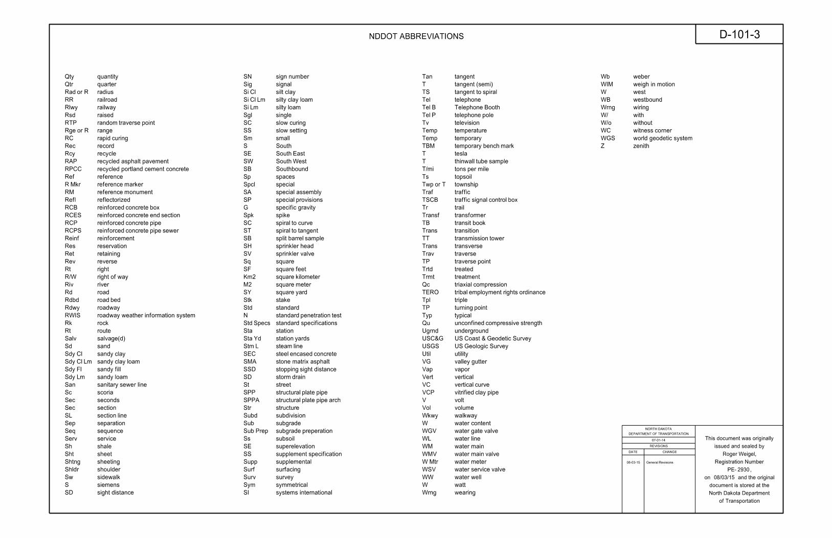
Qty quantity
Qtr quarter
R orRad radius
RR railroad
Rlwy railway
Rsd raised
RTP point traverserandom
R orRge range
RC curingrapid
Rec record
Rcy recycle
RPCC
Ref reference
MkrR markerreference
RM monumentreference
Refl reflectorized
RCB box concretereinforced
RCES section end concretereinforced
RCP pipe concretereinforced
RCPS sewer pipe concretereinforced
Reinf reinforcement
Res reservation
Ret retaining
Rev reverse
Rt right
R/W way ofright
Riv river
Rd road
Rdbd bedroad
Rdwy roadway
RWIS
Rk rock
Rt route
Salv salvage(d)
Sd sand
ClSdy claysandy
Lm ClSdy loam claysandy
FlSdy fillsandy
LmSdy loamsandy
San line sewersanitary
Sc scoria
Sec seconds
Sec section
SL linesection
Sep separation
Seq sequence
Serv service
Sh shale
Sht sheet
Shtng sheeting
Shldr shoulder
Sw sidewalk
S siemens
SD distancesight
Sig signal
ClSi claysilt
Lm ClSi loam claysilty
LmSi loamsilty
Sgl single
SC curingslow
SS settingslow
Sm small
S South
SE EastSouth
SW WestSouth
SB Southbound
Sp spaces
Spcl special
SP provisionsspecial
G gravityspecific
Spk spike
SC curve tospiral
ST tangent tospiral
SB sample barrelsplit
SH headsprinkler
SV valvesprinkler
Sq square
SF feetsquare
Km2 kilometersquare
M2 metersquare
SY yardsquare
Stk stake
Std standard
N test penetrationstandard
SpecsStd
Sta station
YdSta yardsstation
LStm linesteam
SEC concrete encasedsteel
SSD distance sightstopping
SD drainstorm
St street
SPP pipe platestructural
SPPA arch pipe platestructural
Str structure
Subd subdivision
Sub subgrade
PrepSub preperationsubgrade
Ss subsoil
SE superelevation
SS specificationsupplement
Supp supplemental
Surf surfacing
Surv survey
Sym symmetrical
SI
Tan tangent
T (semi)tangent
TS spiral totangent
Tel telephone
BTel BoothTelephone
PTel poletelephone
Tv television
Temp temperature
Temp temporary
TBM mark benchtemporary
T tesla
T sample tubethinwall
T/mi mile pertons
Ts topsoil
T orTwp township
Traf traffic
TSCB box control signaltraffic
Tr trail
Transf transformer
TB booktransit
Trans transition
TT towertransmission
Trans transverse
Trav traverse
TP pointtraverse
Trtd treated
Trmt treatment
Qc compressiontriaxial
TERO ordinance rights employmenttribal
Tpl triple
TP pointturning
Typ typical
Qu strength compressiveunconfined
Ugrnd underground
USC&G Survey Geodetic & CoastUS
USGS Survey GeologicUS
Util utility
VG guttervalley
Vap vapor
Vert vertical
VC curvevertical
VCP pipe clayvitrified
V volt
Vol volume
Wkwy walkway
W contentwater
WGV valve gatewater
WL linewater
WM mainwater
WMV valve mainwater
MtrW meterwater
WSV valve servicewater
WW wellwater
W watt
Wrng wearing
Wb weber
WIM
W west
WB westbound
Wrng wiring
W/ with
W/o without
WC cornerwitness
WGS
Z zenith
SA special assembly
SN sign number
RAP recycled asphalt pavement
recycled portland cement concrete
roadway weather information system
standard specifications
systems international
weigh in motion
world geodetic system
SMA stone matrix asphalt
REVISIONS
DATE CHANGE
DEPARTMENT OF TRANSPORTATION
NORTH DAKOTA
of Transportation
North Dakota Department
document is stored at the
on and the original
PE- ,
Registration Number
issued and sealed by
This document was originally
NDDOT ABBREVIATIONS D-101-3
07-01-14
2930
Roger Weigel,
08/03/15
General Revisions 08-03-15
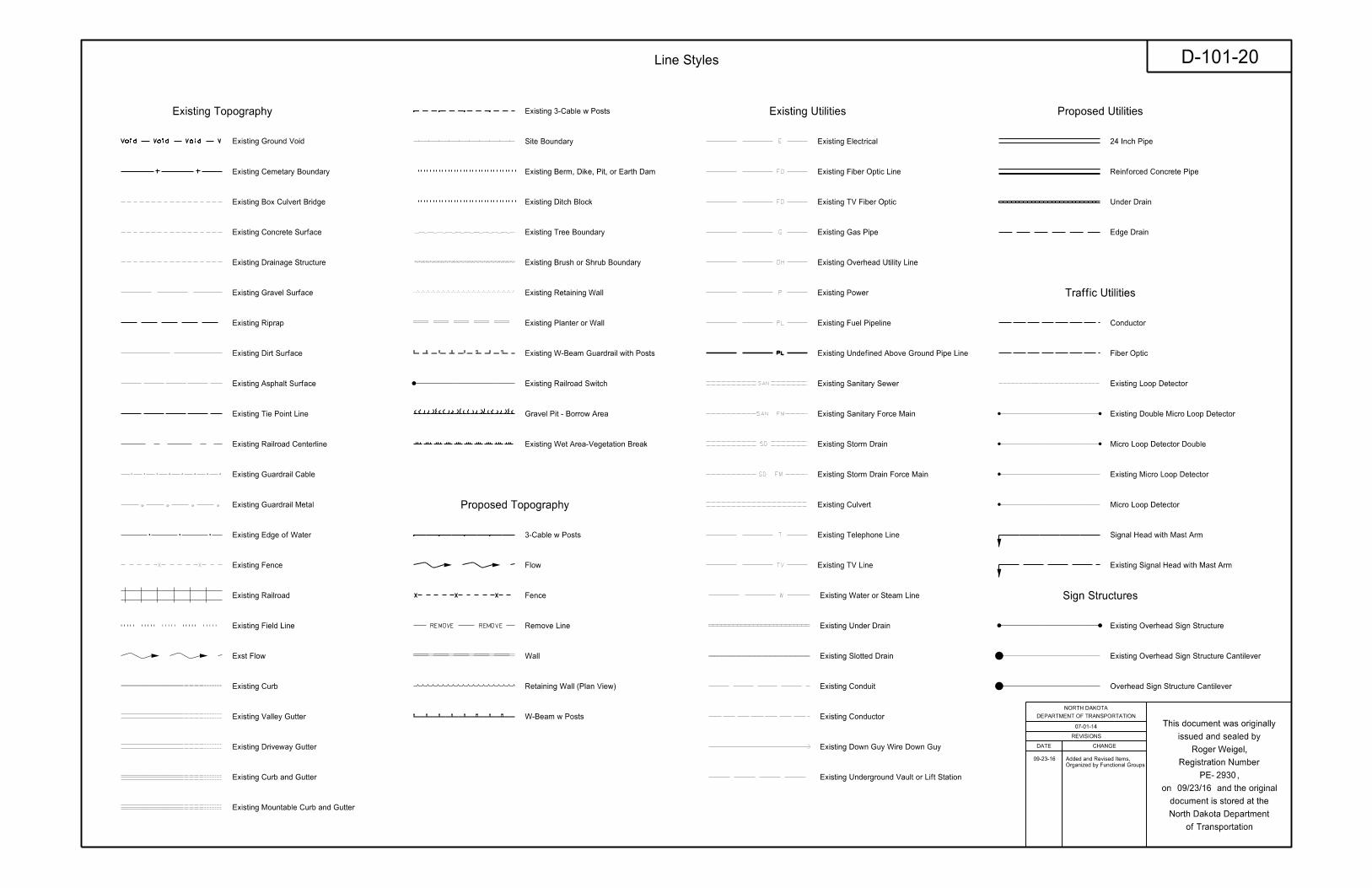
Edge Drain
Existing Electrical
Existing Fiber Optic Line
Existing TV Fiber Optic
Existing Gas Pipe
Existing Overhead Utility Line
Existing Power
Existing Fuel Pipeline
Existing Undefined Above Ground Pipe Line
Remove Line
Existing Telephone Line
Existing TV Line
Existing Water or Steam Line
Existing Under Drain
Under Drain
Wall Existing Slotted Drain
Existing Cemetary Boundary
Existing Box Culvert Bridge
Existing Concrete Surface
Existing Drainage Structure
Existing Gravel Surface
Existing Riprap
Existing Underground Vault or Lift Station
Existing Dirt Surface
Existing Conduit
Existing Conductor
Conductor
Fiber Optic
Existing Loop DetectorExisting Asphalt Surface
Existing Tie Point Line
Existing Railroad Centerline
Existing Guardrail Cable
Existing Guardrail Metal
Existing Edge of Water
Existing Down Guy Wire Down Guy
Existing Fence
Existing Railroad
Existing Sanitary Force Main
Existing Storm Drain
Existing Storm Drain Force Main
Fence
Existing Field Line
Exst Flow
Flow
Existing Culvert
Existing Curb
Existing Valley Gutter
Existing Driveway Gutter
Existing Curb and Gutter
Existing Mountable Curb and Gutter
Existing Double Micro Loop Detector
Micro Loop Detector Double
Existing Overhead Sign Structure
Existing Micro Loop Detector
Micro Loop Detector
Existing Overhead Sign Structure Cantilever
Existing Railroad Switch
Overhead Sign Structure Cantilever
24 Inch Pipe
Reinforced Concrete Pipe
Signal Head with Mast Arm
Existing Signal Head with Mast Arm
3-Cable w Posts
Existing 3-Cable w Posts
Site Boundary
Existing Berm, Dike, Pit, or Earth Dam
Existing Ditch Block
Gravel Pit - Borrow Area
Existing Tree Boundary
Existing Brush or Shrub Boundary
Existing Retaining Wall
Existing Planter or Wall
Retaining Wall (Plan View)
W-Beam w Posts
Existing W-Beam Guardrail with Posts
Existing Sanitary Sewer
Existing Wet Area-Vegetation Break
Existing Ground Void
Line Styles
2930
Roger Weigel,
D-101-20
07-01-14
09/23/16
Existing Utilities Proposed Utilities
Traffic Utilities
Proposed Topography
Existing Topography
Sign Structures
REVISIONS
DATE CHANGE
DEPARTMENT OF TRANSPORTATION
NORTH DAKOTA
of Transportation
North Dakota Department
document is stored at the
on and the original
PE- ,
Registration Number
issued and sealed by
This document was originally
Organized by Functional Groups
Added and Revised Items, 09-23-16
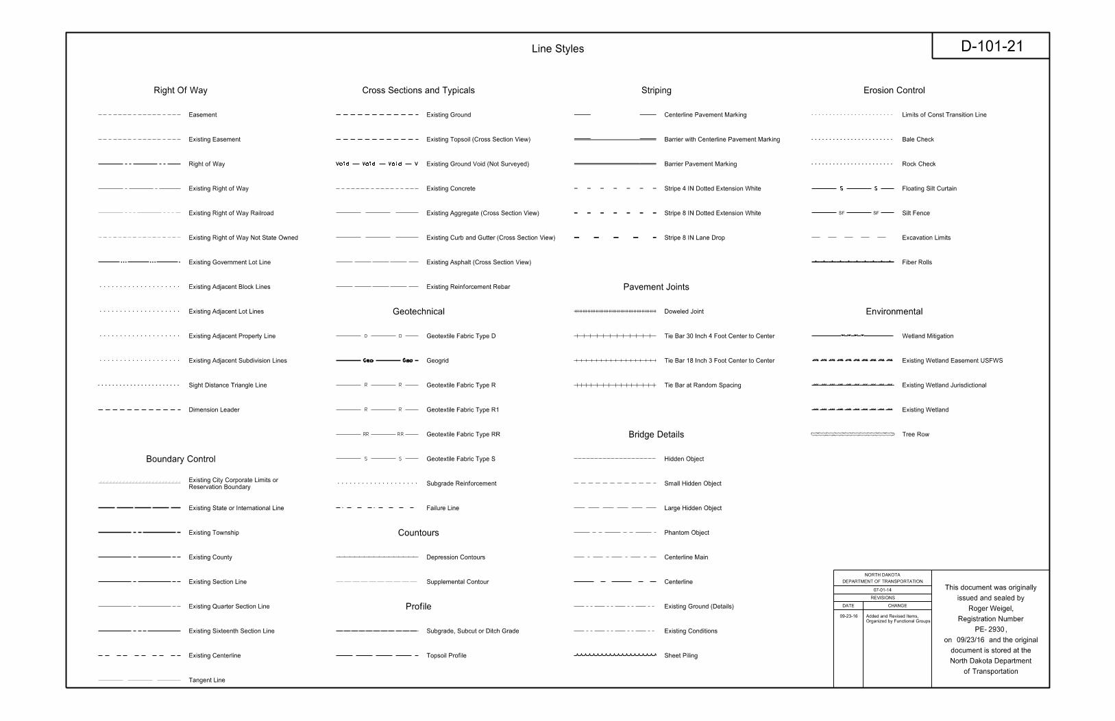
Limits of Const Transition Line
Bale Check
Rock Check
Sight Distance Triangle Line
Small Hidden Object
Existing Ground
Existing Topsoil (Cross Section View)
Large Hidden Object
Geotextile Fabric Type D
Geogrid
Geotextile Fabric Type R
Geotextile Fabric Type R1
Geotextile Fabric Type RR
Geotextile Fabric Type S
Floating Silt Curtain
Centerline Pavement Marking
Barrier with Centerline Pavement Marking
Barrier Pavement Marking
Stripe 4 IN Dotted Extension White
Stripe 8 IN Dotted Extension White
Stripe 8 IN Lane Drop
Wetland Mitigation
Easement
Existing Concrete
Existing Easement
Existing Aggregate (Cross Section View)
Existing Curb and Gutter (Cross Section View)
Tangent Line
Hidden Object
Topsoil Profile
Subgrade, Subcut or Ditch Grade
Existing Asphalt (Cross Section View)
Existing Reinforcement Rebar
Existing State or International Line
Existing Quarter Section Line
Existing County
Existing Section Line
Existing Township
Centerline
Existing Centerline
Supplemental Contour
Right of Way
Existing Right of Way
Existing Right of Way Railroad
Failure Line
Existing Conditions
Existing Ground (Details)
Existing Sixteenth Section Line
Existing Right of Way Not State Owned
Phantom Object
Centerline Main
Excavation Limits
Existing Government Lot Line
Existing Adjacent Block Lines
Existing Adjacent Lot Lines
Existing Adjacent Property Line
Existing Adjacent Subdivision Lines
Subgrade Reinforcement
Silt Fence
Tie Bar at Random Spacing
Fiber Rolls
Doweled Joint
Tie Bar 30 Inch 4 Foot Center to Center
Tie Bar 18 Inch 3 Foot Center to Center
Depression Contours
Tree Row
Sheet Piling
Existing Wetland Easement USFWS
Existing Wetland Jurisdictional
Existing Wetland
Reservation Boundary
Existing City Corporate Limits or
Existing Ground Void (Not Surveyed)
Dimension Leader
REVISIONS
DATE CHANGE
DEPARTMENT OF TRANSPORTATION
NORTH DAKOTA
of Transportation
North Dakota Department
document is stored at the
on and the original
PE- ,
Registration Number
issued and sealed by
This document was originally
Line Styles
2930
Roger Weigel,
09/23/16
D-101-21
07-01-14
Erosion Control
Environmental
Right Of Way
Geotechnical
StripingCross Sections and Typicals
Boundary Control
Pavement Joints
Countours
Profile
Organized by Functional Groups
Added and Revised Items, 09-23-16
Bridge Details
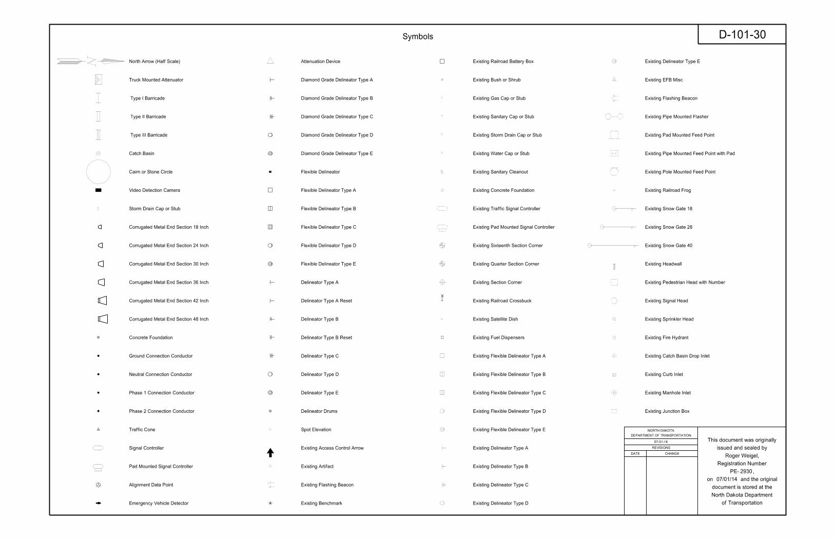
North Arrow (Half Scale)
Truck Mounted Attenuator
Type I Barricade
Type II Barricade
Type III Barricade
Catch Basin
Cairn or Stone Circle
Video Detection Camera
Storm Drain Cap or Stub
Corrugated Metal End Section 18 Inch
Corrugated Metal End Section 24 Inch
Corrugated Metal End Section 30 Inch
Corrugated Metal End Section 36 Inch
Corrugated Metal End Section 42 Inch
Corrugated Metal End Section 48 Inch
Concrete Foundation
Ground Connection Conductor
Neutral Connection Conductor
Phase 1 Connection Conductor
Phase 2 Connection Conductor
Traffic Cone
Signal Controller
Pad Mounted Signal Controller
Alignment Data Point
Emergency Vehicle Detector
Attenuation Device
Diamond Grade Delineator Type A
Diamond Grade Delineator Type B
Diamond Grade Delineator Type C
Diamond Grade Delineator Type D
Diamond Grade Delineator Type E
Flexible Delineator
Flexible Delineator Type A
Flexible Delineator Type B
Flexible Delineator Type C
Flexible Delineator Type D
Flexible Delineator Type E
Delineator Type A
Delineator Type A Reset
Delineator Type B
Delineator Type B Reset
Delineator Type C
Delineator Type D
Delineator Type E
Delineator Drums
Spot Elevation
Existing Access Control Arrow
Existing Artifact
Existing Flashing Beacon
Existing Benchmark
Existing Railroad Battery Box
Existing Bush or Shrub
Existing Gas Cap or Stub
Existing Sanitary Cap or Stub
Existing Storm Drain Cap or Stub
Existing Water Cap or Stub
Existing Sanitary Cleanout
Existing Concrete Foundation
Existing Traffic Signal Controller
Existing Pad Mounted Signal Controller
Existing Sixteenth Section Corner
Existing Quarter Section Corner
Existing Section Corner
Existing Railroad Crossbuck
Existing Satellite Dish
Existing Fuel Dispensers
Existing Flexible Delineator Type A
Existing Flexible Delineator Type B
Existing Flexible Delineator Type C
Existing Flexible Delineator Type D
Existing Flexible Delineator Type E
Existing Delineator Type A
Existing Delineator Type B
Existing Delineator Type C
Existing Delineator Type D
Existing Delineator Type E
Existing EFB Misc
Existing Flashing Beacon
Existing Pipe Mounted Flasher
Existing Pad Mounted Feed Point
Existing Pipe Mounted Feed Point with Pad
Existing Pole Mounted Feed Point
Existing Railroad Frog
Existing Snow Gate 18
Existing Snow Gate 28
Existing Snow Gate 40
Existing Headwall
Existing Pedestrian Head with Number
Existing Signal Head
Existing Sprinkler Head
Existing Fire Hydrant
Existing Catch Basin Drop Inlet
Existing Curb Inlet
Existing Manhole Inlet
Existing Junction Box
REVISIONS
DATE CHANGE
DEPARTMENT OF TRANSPORTATION
NORTH DAKOTA
of Transportation
North Dakota Department
document is stored at the
on and the original
PE- ,
Registration Number
issued and sealed by
This document was originally
Symbols
2930
Roger Weigel,
D-101-30
07-01-14
07/01/14
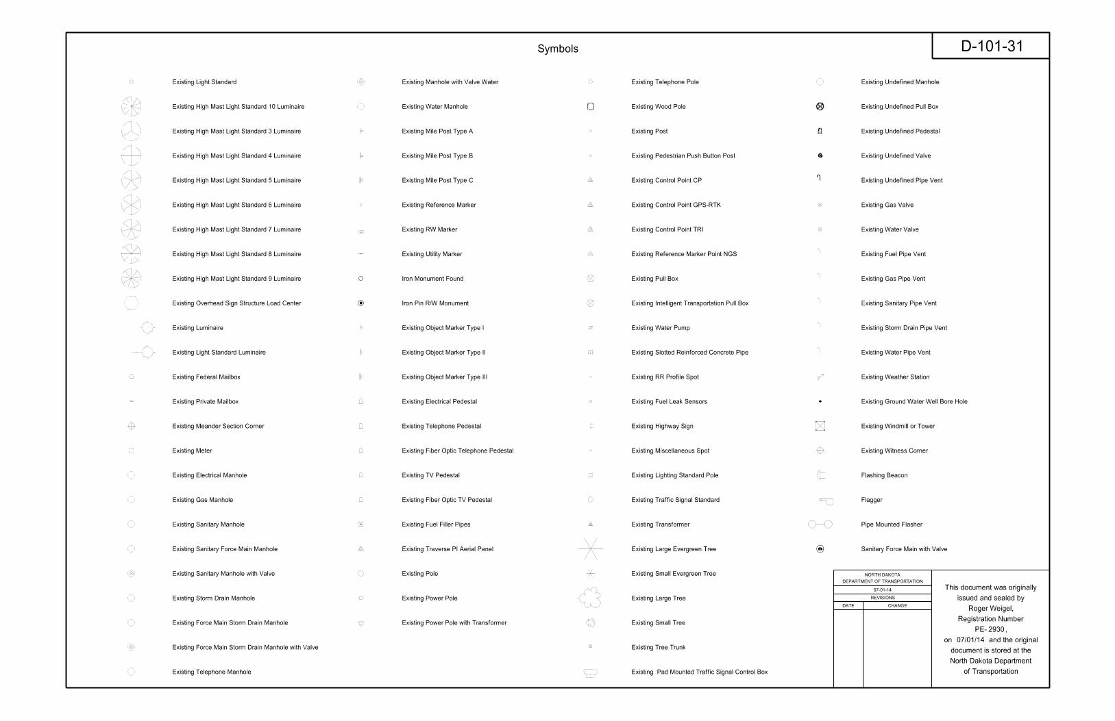
Existing Light Standard
Existing High Mast Light Standard 10 Luminaire
Existing High Mast Light Standard 3 Luminaire
Existing High Mast Light Standard 4 Luminaire
Existing High Mast Light Standard 5 Luminaire
Existing High Mast Light Standard 6 Luminaire
Existing High Mast Light Standard 7 Luminaire
Existing High Mast Light Standard 8 Luminaire
Existing High Mast Light Standard 9 Luminaire
Existing Overhead Sign Structure Load Center
Existing Luminaire
Existing Light Standard Luminaire
Existing Federal Mailbox
Existing Private Mailbox
Existing Meander Section Corner
Existing Meter
Existing Electrical Manhole
Existing Gas Manhole
Existing Sanitary Manhole
Existing Sanitary Force Main Manhole
Existing Sanitary Manhole with Valve
Existing Storm Drain Manhole
Existing Force Main Storm Drain Manhole
Existing Force Main Storm Drain Manhole with Valve
Existing Telephone Manhole
Existing Manhole with Valve Water
Existing Water Manhole
Existing Mile Post Type A
Existing Mile Post Type B
Existing Mile Post Type C
Existing Reference Marker
Existing RW Marker
Existing Utility Marker
Iron Pin R/W Monument
Existing Object Marker Type I
Existing Object Marker Type II
Existing Object Marker Type III
Existing Electrical Pedestal
Existing Telephone Pedestal
Existing Fiber Optic Telephone Pedestal
Existing TV Pedestal
Existing Fiber Optic TV Pedestal
Existing Fuel Filler Pipes
Existing Traverse PI Aerial Panel
Existing Pole
Existing Power Pole
Existing Power Pole with Transformer
Existing Telephone Pole
Existing Wood Pole
Existing Post
Existing Pedestrian Push Button Post
Existing Control Point CP
Existing Control Point GPS-RTK
Existing Control Point TRI
Existing Reference Marker Point NGS
Existing Pull Box
Existing Intelligent Transportation Pull Box
Existing Water Pump
Existing Slotted Reinforced Concrete Pipe
Existing RR Profile Spot
Existing Fuel Leak Sensors
Existing Highway Sign
Existing Miscellaneous Spot
Existing Lighting Standard Pole
Existing Traffic Signal Standard
Existing Transformer
Existing Large Evergreen Tree
Existing Small Evergreen Tree
Existing Large Tree
Existing Small Tree
Existing Tree Trunk
Existing Pad Mounted Traffic Signal Control Box
Existing Undefined Manhole
Existing Undefined Pull Box
Existing Undefined Pedestal
Existing Undefined Valve
Existing Undefined Pipe Vent
Existing Gas Valve
Existing Water Valve
Existing Fuel Pipe Vent
Existing Gas Pipe Vent
Existing Sanitary Pipe Vent
Existing Storm Drain Pipe Vent
Existing Water Pipe Vent
Existing Weather Station
Existing Ground Water Well Bore Hole
Existing Windmill or Tower
Existing Witness Corner
Flashing Beacon
Flagger
Pipe Mounted Flasher
Sanitary Force Main with Valve
Iron Monument Found
REVISIONS
DATE CHANGE
DEPARTMENT OF TRANSPORTATION
NORTH DAKOTA
of Transportation
North Dakota Department
document is stored at the
on and the original
PE- ,
Registration Number
issued and sealed by
This document was originally
Symbols
2930
Roger Weigel,
D-101-31
07-01-14
07/01/14
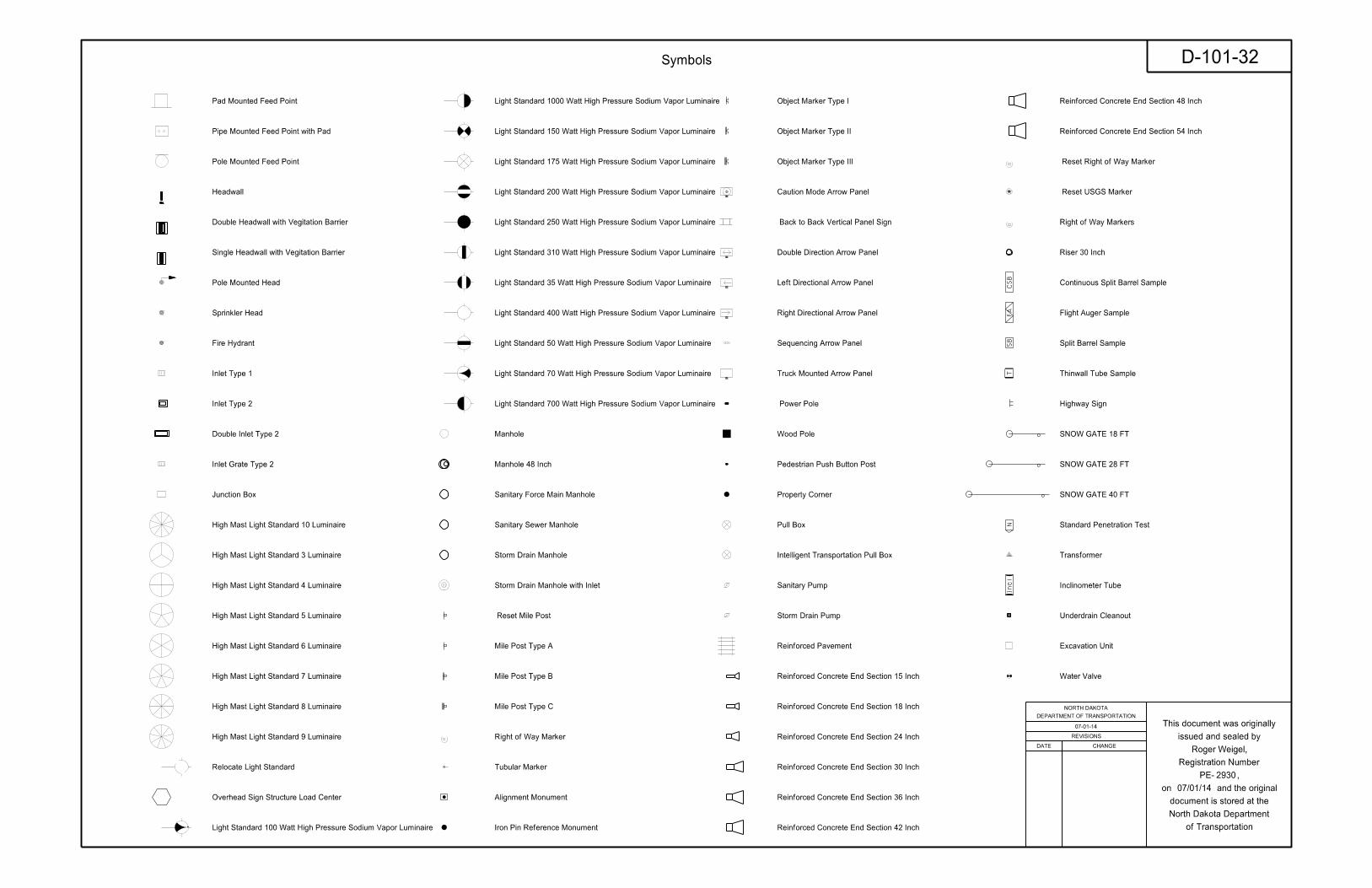
Pad Mounted Feed Point
Pipe Mounted Feed Point with Pad
Pole Mounted Feed Point
Headwall
Double Headwall with Vegitation Barrier
Single Headwall with Vegitation Barrier
Pole Mounted Head
Sprinkler Head
Fire Hydrant
Inlet Type 1
Inlet Type 2
Double Inlet Type 2
Inlet Grate Type 2
Junction Box
High Mast Light Standard 10 Luminaire
High Mast Light Standard 3 Luminaire
High Mast Light Standard 4 Luminaire
High Mast Light Standard 5 Luminaire
High Mast Light Standard 6 Luminaire
High Mast Light Standard 7 Luminaire
High Mast Light Standard 8 Luminaire
High Mast Light Standard 9 Luminaire
Relocate Light Standard
Overhead Sign Structure Load Center
Light Standard 100 Watt High Pressure Sodium Vapor Luminaire
Light Standard 1000 Watt High Pressure Sodium Vapor Luminaire
Light Standard 150 Watt High Pressure Sodium Vapor Luminaire
Light Standard 175 Watt High Pressure Sodium Vapor Luminaire
Light Standard 200 Watt High Pressure Sodium Vapor Luminaire
Light Standard 250 Watt High Pressure Sodium Vapor Luminaire
Light Standard 310 Watt High Pressure Sodium Vapor Luminaire
Light Standard 35 Watt High Pressure Sodium Vapor Luminaire
Light Standard 400 Watt High Pressure Sodium Vapor Luminaire
Light Standard 50 Watt High Pressure Sodium Vapor Luminaire
Light Standard 70 Watt High Pressure Sodium Vapor Luminaire
Light Standard 700 Watt High Pressure Sodium Vapor Luminaire
Manhole
Manhole 48 Inch
Sanitary Force Main Manhole
Sanitary Sewer Manhole
Storm Drain Manhole
Storm Drain Manhole with Inlet
Reset Mile Post
Mile Post Type A
Mile Post Type B
Mile Post Type C
Right of Way Marker
Tubular Marker
Object Marker Type I
Object Marker Type II
Object Marker Type III
Caution Mode Arrow Panel
Back to Back Vertical Panel Sign
Double Direction Arrow Panel
Left Directional Arrow Panel
Right Directional Arrow Panel
Sequencing Arrow Panel
Truck Mounted Arrow Panel
Power Pole
Wood Pole
Pedestrian Push Button Post
Property Corner
Pull Box
Intelligent Transportation Pull Box
Sanitary Pump
Storm Drain Pump
Reinforced Pavement
Reinforced Concrete End Section 15 Inch
Reinforced Concrete End Section 18 Inch
Reinforced Concrete End Section 24 Inch
Reinforced Concrete End Section 30 Inch
Reinforced Concrete End Section 36 Inch
Reinforced Concrete End Section 42 Inch
Reinforced Concrete End Section 48 Inch
Reinforced Concrete End Section 54 Inch
Reset Right of Way Marker
Reset USGS Marker
Right of Way Markers
Riser 30 Inch
Continuous Split Barrel Sample
Flight Auger Sample
Split Barrel Sample
Thinwall Tube Sample
Highway Sign
SNOW GATE 18 FT
SNOW GATE 28 FT
SNOW GATE 40 FT
Standard Penetration Test
Transformer
Inclinometer Tube
Underdrain Cleanout
Excavation Unit
Water Valve
HDWL
CS
BF
AS
BT
Incl
N
Alignment Monument
Iron Pin Reference Monument
REVISIONS
DATE CHANGE
DEPARTMENT OF TRANSPORTATION
NORTH DAKOTA
of Transportation
North Dakota Department
document is stored at the
on and the original
PE- ,
Registration Number
issued and sealed by
This document was originally
Symbols
2930
Roger Weigel,
07-01-14
07/01/14
D-101-32
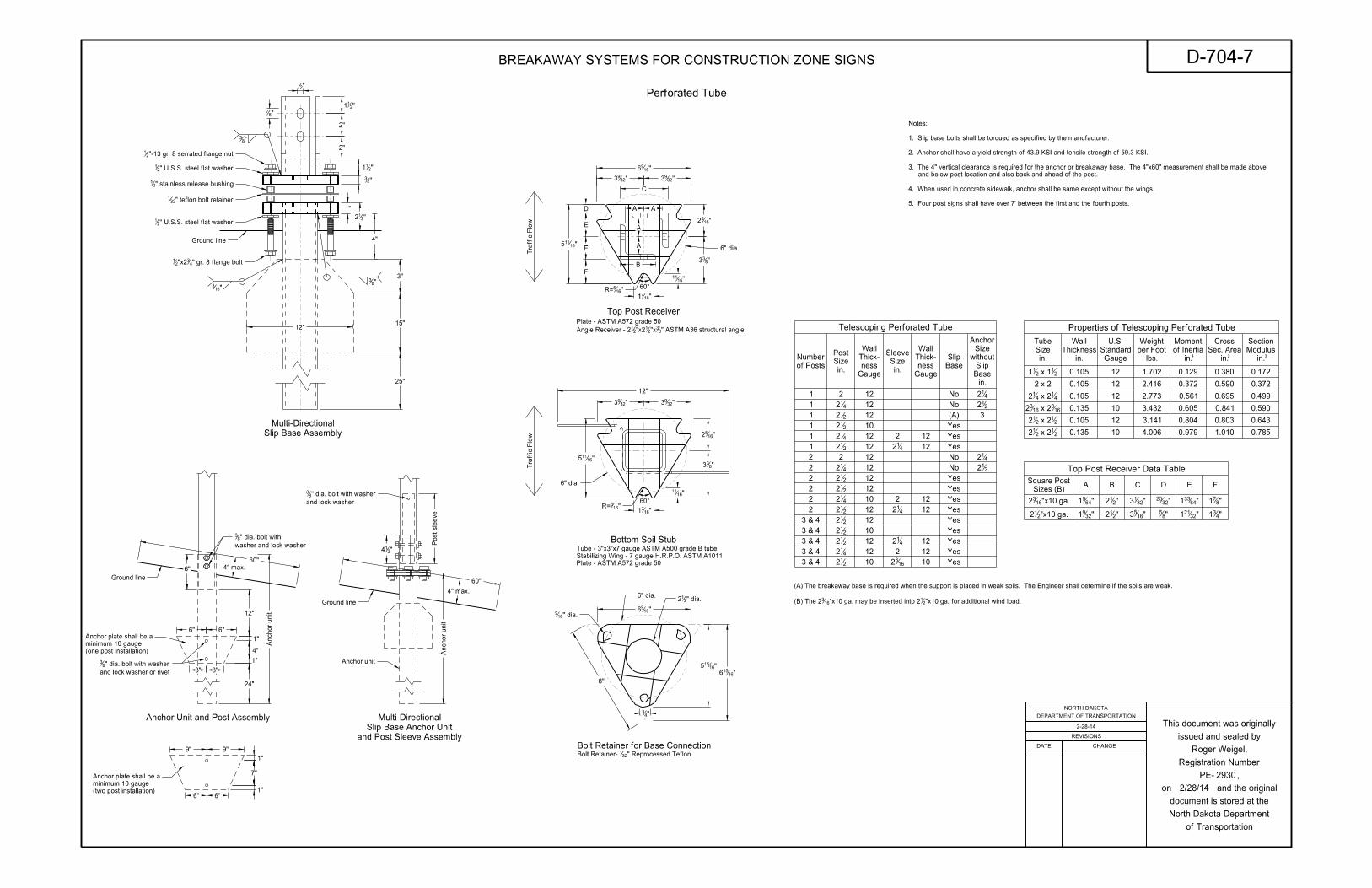
Top Post Receiver Data Table
A B C D E FSizes (B)
Square Post
Perforated Tube
Slip Base Assembly
Multi-Directional
Bolt Retainer for Base Connection
Ground line
Ground line
12"
25"
15"
3"
4"
"21
"87
"211
2"
2"
"211
"43
1"
"212
8"
"1696
"16155
"16156
"43
60"
6"
6" 6"
3" 3"
4"
24"
1"
1"
12"
6" 6"
7"
1"
1"
"16115
12"
"3293 "32
93
"1652
"833
"1611
"16115
D
E
E
F
"1652
"833
"1611
"1671
"3293 "32
93
"1696
C
A
A
B
A A
60^
6" dia.
6" dia.
6" dia.
9" 9"
60^
Traffic Flo
w
Anchor unit
Ground line
Anchor unit
Post sleeve
"214
Traffic Flo
w
"1671
of Posts
Number
Gauge
ness
Thick-
Wall
Gauge
ness
Thick-
Wall
Base
Slip Gauge
Standard
U.S.
1
1
1
1
1
1
2
2
2
3 & 4
3 & 4
3 & 4
3 & 4
3 & 4
2 12
12
12
12
12
12
12
12
12
12
10
10
10
12
12
12
12
10
No
No
Yes
Yes
Yes
Yes
Yes
Yes
Yes
Yes
Yes
0.105
0.105
0.105
0.135
0.135
12
12
12
12
10
10
1.702
2.416
2.773
3.432
3.141
4.006
0.129
0.372
0.561
0.605
0.804
0.979
0.380
0.590
0.695
0.841
0.803
1.010
0.172
0.372
0.499
0.590
0.643
"3291
"6491
"212
"212
"1653
"3213
"85
"3225
"32211
"64331
"431
"871
"x10 ga.212
"x10 ga.1632
"-13 gr. 8 serrated flange nut21
" U.S.S. steel flat washer21
" stainless release bushing21
" U.S.S. steel flat washer21
" gr. 8 flange bolt43"x22
1
"83
"163
"83
washer and lock washer
" dia. bolt with83
and lock washer or rivet
" dia. bolt with washer83
and lock washer
" dia. bolt with washer83
" dia.169
" dia.212
" Reprocessed Teflon321Bolt Retainer-
in.
of Inertia
Moment
2 x 2
(A)
Telescoping Perforated Tube
163 x 216
32
21 x 22
12
21 x 22
12
41 x 24
12
21 x 12
11
4 2 3in.
Modulus
Section
in.
Sec. Area
Cross
in.
Size
Post
in.
Size
Sleeve
in.
Base
Slip
without
Size
Anchor
412
212
412
412
1632
412
212
212
412
212
412
212
212
212
212
412
212
in.
Thickness
Wall
lbs.
per Foot
Weight
2
2
412
212
2 12 Yes212
2 12 Yes412
2 12 12 Yes4122
12
2 12
10
3
2
No
No
0.105
0.785
Anchor unit
" teflon bolt retainer321
4" max.
4" max.
Anchor Unit and Post Assembly
(one post installation)
minimum 10 gauge
Anchor plate shall be a
(two post installation)
minimum 10 gauge
Anchor plate shall be a
Top Post Receiver
Bottom Soil Stub
in.
Size
Tube
"x10 ga. for additional wind load.21"x10 ga. may be inserted into 216
3(B) The 2
(A) The breakaway base is required when the support is placed in weak soils. The Engineer shall determine if the soils are weak.
Properties of Telescoping Perforated Tube
60"
"165R=
"165R=
and Post Sleeve Assembly
Slip Base Anchor Unit
Multi-Directional
Plate - ASTM A572 grade 50
Stabilizing Wing - 7 gauge H.R.P.O. ASTM A1011
Tube - 3"x3"x7 gauge ASTM A500 grade B tube
5. Four post signs shall have over 7’ between the first and the fourth posts.
4. When used in concrete sidewalk, anchor shall be same except without the wings.
and below post location and also back and ahead of the post.
3. The 4" vertical clearance is required for the anchor or breakaway base. The 4"x60" measurement shall be made above
2. Anchor shall have a yield strength of 43.9 KSI and tensile strength of 59.3 KSI.
1. Slip base bolts shall be torqued as specified by the manufacturer.
Notes:
" ASTM A36 structural angle83"x2
1"x221Angle Receiver - 2
Plate - ASTM A572 grade 50
2-28-14
2930
BREAKAWAY SYSTEMS FOR CONSTRUCTION ZONE SIGNS D-704-7
REVISIONS
DATE CHANGE
DEPARTMENT OF TRANSPORTATION
NORTH DAKOTA
of Transportation
North Dakota Department
document is stored at the
on and the original
PE- ,
Registration Number
issued and sealed by
This document was originally
Roger Weigel,
2/28/14
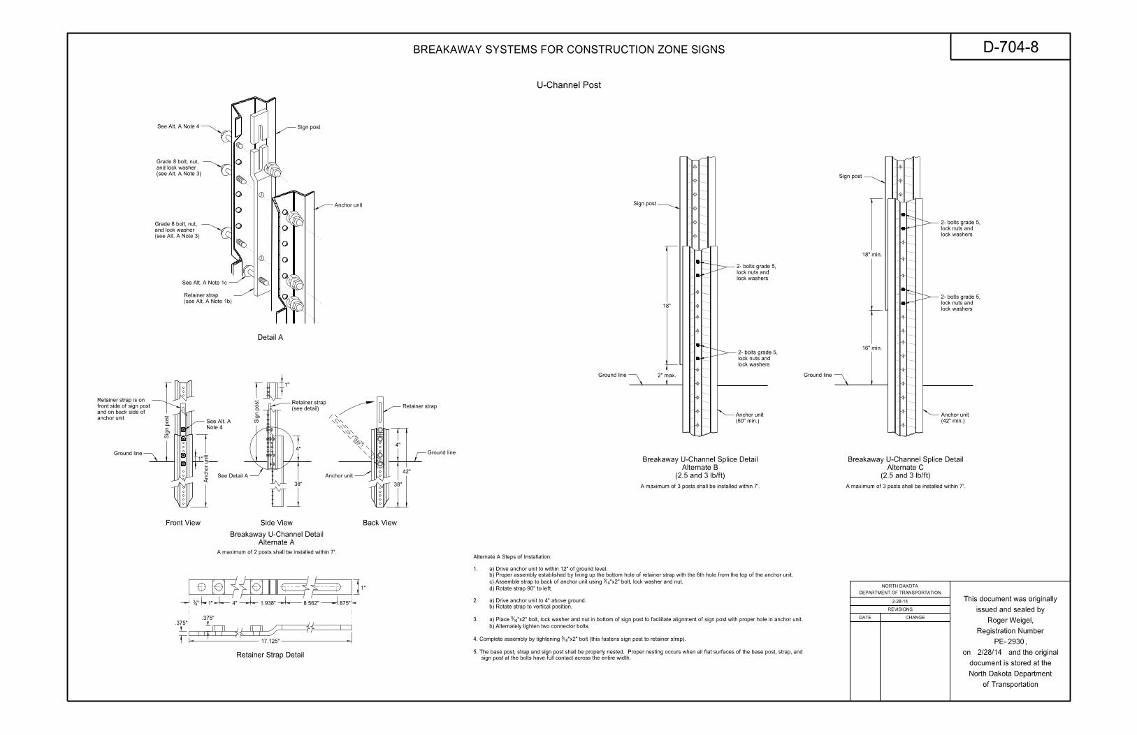
Front View Side View
Anchor unit
Ground line1"
"43 1" 4" 1.938" 8.562" .875"
1"
.375".375"
17.125"
1"
U-Channel Post
Retainer strap
Anchor unit
4"
38"
42"
Ground line
38"
4"
Retainer Strap Detail
Sign post
Sig
n p
ost
Sig
n p
ost
Anchor unit
Back View
Sign post
Ground line
Sign post
Ground line
16" min.
18" min.
2" max.
Alternate A
Breakaway U-Channel Detail
Detail A
(see detail)
Retainer strap
See Detail A
See Alt. A Note 4
See Alt. A Note 1c
(see Alt. A Note 1b)
Retainer strap
(see Alt. A Note 3)
and lock washer
Grade 8 bolt, nut,
(see Alt. A Note 3)
and lock washer
Grade 8 bolt, nut,
18"
Note 4
See Alt. Aanchor unit
and on back side of
front side of sign post
Retainer strap is on
(60" min.)
Anchor unit
(42" min.)
Anchor unit
lock washers
lock nuts and
2- bolts grade 5,
lock washers
lock nuts and
2- bolts grade 5,
lock washers
lock nuts and
2- bolts grade 5,
lock washers
lock nuts and
2- bolts grade 5,
(2.5 and 3 lb/ft)
Alternate C
Breakaway U-Channel Splice Detail
(2.5 and 3 lb/ft)
Alternate B
Breakaway U-Channel Splice Detail
A maximum of 2 posts shall be installed within 7’.
A maximum of 3 posts shall be installed within 7’.A maximum of 3 posts shall be installed within 7’.
sign post at the bolts have full contact across the entire width.
5. The base post, strap and sign post shall be properly nested. Proper nesting occurs when all flat surfaces of the base post, strap, and
"x2" bolt (this fastens sign post to retainer strap).1654. Complete assembly by tightening
b) Alternately tighten two connector bolts.
"x2" bolt, lock washer and nut in bottom of sign post to facilitate alignment of sign post with proper hole in anchor unit.165a) Place 3.
b) Rotate strap to vertical position.
a) Drive anchor unit to 4" above ground.2.
d) Rotate strap 90° to left.
"x2" bolt, lock washer and nut.165c) Assemble strap to back of anchor unit using
b) Proper assembly established by lining up the bottom hole of retainer strap with the 6th hole from the top of the anchor unit.
a) Drive anchor unit to within 12" of ground level. 1.
Alternate A Steps of Installation:
REVISIONS
DATE CHANGE
DEPARTMENT OF TRANSPORTATION
NORTH DAKOTA
of Transportation
North Dakota Department
document is stored at the
on and the original
PE- ,
Registration Number
issued and sealed by
This document was originally2-28-14
2930
BREAKAWAY SYSTEMS FOR CONSTRUCTION ZONE SIGNS D-704-8
Roger Weigel,
2/28/14
3.15" 29.7" 3.15"
36"
4.5"
9"B
4.5"
18"
8-17-17 Added sign & background color
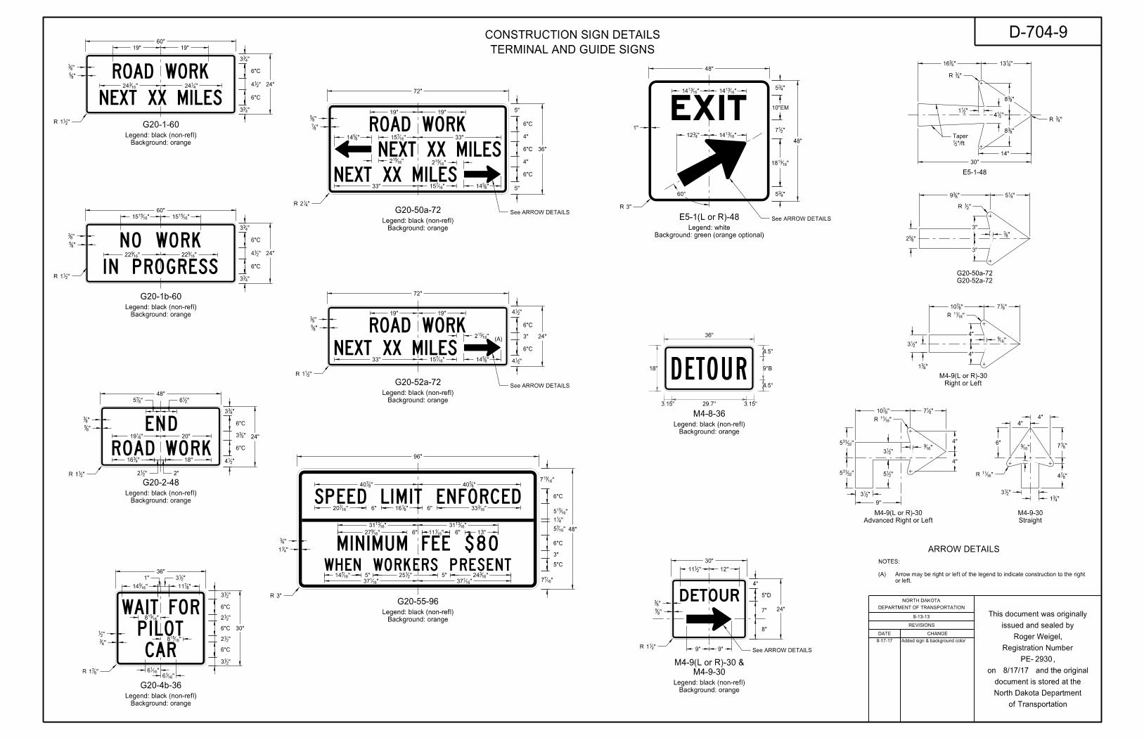
Background: orange
Legend: black (non-refl)
48"
"216"8
75
"83
"85
"211R
24"
"433
"433
"214
6"C
6"C
20""4119
"4316 18"
2""212
Background: orange
Legend: black (non-refl)
"4124"16
324 24"
"433
"214
"433
6"C
6"C
60"
"211R
"83
"85
19"19"
G20-1-60
Background: orange
Legend: black (non-refl)
24"
"433
"214
"433
6"C
6"C
60"
"85
"83
"211R
"161515"16
1515
G20-1b-60
Background: orange
Legend: black (non-refl)
G20-50a-72
36"
5"
4"
5"
6"C
72"
19"19"
6"C
4"
6"C
33""16715"8
514
"16152 "16
152
"1671533" "8
514
"85
"87
"412R
Background: orange
Legend: black (non-refl)
G20-52a-72
"1671533" "8
514
"16152
19"19"
"85
"83
"211R
24"
"214
3"
"214
6"C
6"C
72"
G20-55-96
Background: orange
Legend: black (non-refl)
48"
"16157
3"
"1677
5"C
6"C
"1675
6"C
96"
"411
"16155
"163336""8
1166""16720
"8740"8
740
"161116""16
927 13"6"
"161331"16
1331
"163245""2
1255""16714
"16137"16
137
3"R
"43
"411
G20-2-48
G20-52a-72
G20-50a-72
"852
"415"8
39
"21R
"83
3"
3"
30"
"213
"213
36"
Background: orange
Legend: black (non-refl)
"212
6"C
G20-4b-36
"16514 "8
711
"2131"
"16158
"16158
"1616
"1616
"21
"43
48"
48"
1"
"435
E5-1-48
See ARROW DETAILS
See ARROW DETAILS
ARROW DETAILS
"16922"16
922
"161314"16
1314
3"R
10"EM
"435
"161518
"217
"161314"4
312
60°
"43R
"4113"4
316
"211
"838
"838
"214
14"
30"
"43R
"/ft21
Taper
6"C
6"C
"212
"871R
Background: orange
Legend: black (non-refl)
24"
4"
5"D
"83
"85
"211R
12""2111
8"
7"
9"9" See ARROW DETAILS
M4-9-30
M4-9(L or R)-30 &
"1611R
"1611R
4"
4"
"874
"817"16
9
"213
"431
6"4"
4"
"8710 "8
17
"169
9"
"213
"213
"215
Advanced Right or Left
M4-9(L or R)-30
Straight
M4-9-30
"32315
"32315
4"
4"
"817"8
710
"213
"169
"1611R
Right or Left
M4-9(L or R)-30
"431
E5-1(L or R)-48
(A)
or left.
Arrow may be right or left of the legend to indicate construction to the right (A)
NOTES:
See ARROW DETAILS
Background: orange
Legend: black (non-refl)
M4-8-36
Background: green (orange optional)
Legend: white
30"
REVISIONS
DATE CHANGE
DEPARTMENT OF TRANSPORTATION
NORTH DAKOTA
of Transportation
North Dakota Department
document is stored at the
on and the original
PE- ,
Registration Number
issued and sealed by
This document was originally8-13-13
2930
CONSTRUCTION SIGN DETAILS D-704-9TERMINAL AND GUIDE SIGNS
Roger Weigel,
8/17/17
Background: orange
Legend: black (non-refl)
48"
48"
3"R
15"15"
"16114"16
114
"873
3"
6"C
6"C
6"C
3"
3"
48"
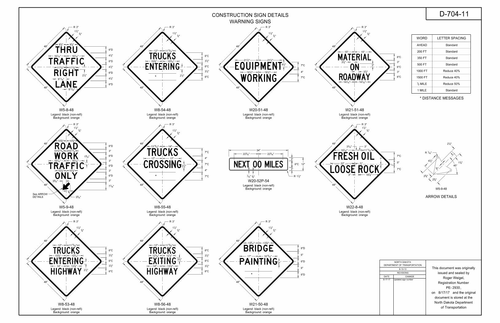
W22-8-48
Background: orange
Legend: black (non-refl)
1"
3"R
48"
7"C
7"C
"411
"43
"411
6"C
6"C
6"C
"411
"43
3"R
48"
48"
W8-56-48
Background: orange
Legend: black (non-refl)
"213
"8112"16
312
"16151112"
"871314"
Background: orange
Legend: black (non-refl)
48"
"4116"4
116
"4121"4
121
7"C
7"C
4"
"43
"411
3"R
48"
"214
W20-51-48
Background: orange
Legend: black (non-refl)
54"
"16322"16
322
12"
3"
6"C
3"
W20-52P-54
"83"16
7
WORD LETTER SPACING
AHEAD Standard
Standard
Standard
Standard
Standard
200 FT
350 FT
500 FT
1000 FT
1500 FT
MILE21
1 MILE
6"D
6"D
48"
Background: orange
Legend: black (non-refl)
3"
"16151617"
"8313"16
513
"43
"411
3"R
48"
6"
6"
* DISTANCE MESSAGES
6"D
"873
W21-50-48
W21-51-48
"43
"161111"16
119
5"22" "21
"87183"
"1633 3"
"213
"213
"211R
Reduce 40%
Reduce 40%
Reduce 50%
ARROW DETAILS
Background: orange
Legend: black (non-refl)
W5-8-48
48"
48"
3"R
"879"8
79
"16116"16
116
"16111"16
111
"16119
"16119
"412
6"D
6"D
6"D
6"D
"214
"214
"214
W5-9-48
48"
W5-9-48
Background: orange
Legend: black (non-refl)
"1691
3"R
48"6"D
6"D
6"D
6"D
3"
3"
3"
"8310"8
310
"161310"16
1310
"16116"16
116
"8110"8
110
3"
"1617
"852
"83
"214
"167R
"412
"811
45°
"852
6"C
6"C
6"C
"213
"213
"212
3"R
48"
48"
W8-53-48
Background: orange
Legend: black (non-refl)
"16151112"
"16515"8
315
"871314"
"411
"43
"43
"411
"43
"411
6"C
6"C
"213
"213
"212
3"R
48"
48"
W8-54-48
Background: orange
Legend: black (non-refl)
"16151112"
"16515"8
315
"43
"411
W8-55-48
Background: orange
Legend: black (non-refl)
7"C
7"C
4"
4"
"43
"411
3"R
48"
48"
17"17"
14""161513
"213
7"C
6"C
"1693
"1693
DETAILS
See ARROW
*
*
*
8-17-17 Updated sign number
REVISIONS
DATE CHANGE
DEPARTMENT OF TRANSPORTATION
NORTH DAKOTA
of Transportation
North Dakota Department
document is stored at the
on and the original
PE- ,
Registration Number
issued and sealed by
This document was originally8-13-13
D-704-11
2930
CONSTRUCTION SIGN DETAILS
WARNING SIGNS
Roger Weigel,
8/17/17
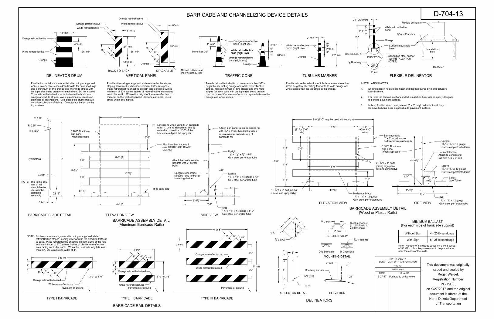
TUBULAR MARKERVERTICAL PANEL
28" min
8" to 12"
4"
4"
TRAFFIC CONE
2" min
4" to 6"
36" min
18" min
DELINEATOR DRUM
6"
3" to 4"
28" min
2"
4"
4" to 6"
More than 36"
6" 6"
6' to 10'
8"
3'-0" to 3'-6"
45°
2' min
3'-0" to 3'-6"
45°
8"
8"
6" 6"45°
5' min
20"
20"
Varies
2" to 6"
3"
3"2"
45°
White retroreflective
Orange retroreflective
Orange retroreflective
Orange
White retroreflective
Orange
band (night use)
White retroreflective
band (night use)
Orange retroreflective
band (night use)
White retroreflective
White retroreflectorized
Orange retroreflectorized
White retroreflectorized
Orange retroreflectorized
band (night use)
White retroreflective
band (night use)
Orange retroreflective
Orange retroreflectorized
White retroreflectorized
3"
3"
28"
2"
PLAN
ELEVATION
DETAIL A
FLEXIBLE DELINEATOR
"435'-2
"214'-1 5'-0"
12"
5'-0"
8"
"214'-7
2" to 6"
6' or 8'
(Aluminum Barricade Rails)
BARRICADE ASSEMBLY DETAIL
1'-8"
1'-8"
"431'-1 "4
34'-7
5'-0"
1'-8"
1'-8"
1'-4" 1'-6"
SIDE VIEW
SIDE VIEW
(Wood or Plastic Rails)
BARRICADE ASSEMBLY DETAIL
5'-0"
Orange
` Roadway
band
White retroreflective
base
Surface mountable
45 lb sand bag
DETAIL)
(see BARRICADE BLADE
Aluminum barricade rail
hollow-profile plastic rails
1" x 8" wood slats or
Barricade rails
"41
Galv steel perforated tube
" x 14 gauge x 12"43" x 14
31
Sleeve
rail and upright (typ)
joining sign panel,
"| x 4" bolts 832 -
sleeve and upright (typ)
"| x 3" bolt joining 831 -
Galv steel perforated tube
" x 5'-0"81" x 2
1" x 1211
Upright
Galv steel perforated tube
" x 14 gauge x 5'-0"43" x 14
31
Skid
"4110
"4116
"| x 5" bolt83rail with
Attach to upright and
Horizontal brace
Galv steel perforated tube
" X 12 gauge43" x 14
31
Sleeve
Galv steel perforated tube
" x 12 gauge21" x 12
11
Upright
Galv steel perforated tube
" x 12 gauge43" x 14
31
SkidGalv steel perforated tube
" x 12 gauge21" x 12
11
Horizontal brace
ELEVATION VIEW
ELEVATION VIEW
"414'-10
Flexible delineator
See DETAIL A
Pavement or ground Pavement or ground Pavement or ground
" OD (min)412
6" 6"
rails)
(9" for 6'-0"
rails)
(9" for 6'-0"
1'-9"4'-6"1'-9"
Orange
STACKABLEBACK TO BACK
36" min
12" max
24" min 36" min
Orange retroreflective
White retroreflective
6"
6"
45°
Orange
(min weight 30 lbs)
Molded rubber base
" | x 3" anchor83
NOTES)
(see INSTALLATION
Galvanized steel anchor
holeInstallation
4'-0"
2'-6"
5'-0"
2'-6"
8" min
Symmetrical
0.812"
0.24"
9"
0.094"
0.625"R
0.12"R
0.25"R
BARRICADE BLADE DETAIL
4" 4"
2"
6"
1"
1"
8"
3"
"83R
"21R
"| (typ)41
"| (typ)41
2"
SECTION VIEW
" min1611
One Direction Bi-Directional
" Fastener163
2" min
MOUNTING DETAIL
DELINEATORS
ELEVATION
4'
REFLECTOR DETAIL
Roadway surface
24"
2' to 8'
TYPE I BARRICADE TYPE II BARRICADE TYPE III BARRICADE
BARRICADE RAIL DETAILS
6'-0" (A)
assembly.
barricade
use with this
acceptable for
type of rail
This is the only NOTE:
8'-0" (6'-0" may be used without sign)
2.0 lb/ft max)(1.12 lb/ft min to Steel u-channel
(when applicable)
sign panel
0.100" Aluminum
(when applicable)
sign panel
0.080" Aluminum
"812'-5
"812'-5
With Sign
Without Sign 4 - 25 lb sandbags
6 - 25 lb sandbags
(see Table)
Ballast
(For each side of barricade support)
MINIMUM BALLAST
than 36", use a rail stripe width of 4".
area facing vehicular traffic. When the barricade length is less
with a minimum of 270 square inches of visible retroreflective
to pass. Place retroreflective sheeting on both sides of the rails
retroreflective stripes, sloping downward in the direction traffic is
For barricade markings use alternating orange and white NOTE:
barricade rail past the uprights.
extend no more than 1'-0" of the
rails: 1) use no sign panel, and 2)
Limitations when using 8'-0" barricade (A)
fastening device
sleeves - use no bolt or
Uprights slide inside
barricade rail
square washer on back side of
" x 1" hex head bolts with a 165with
Attach sign panel to top barricade rail
near the ends of the skids.
of 55 MPH. Sandbags assumed to be placed at or
Note: Number of sandbags based on a wind speed
Remove butyl as close as possible to pavement surface.
In lieu of bolted down base, use an 8" x 8" butyl pad or hot melt butyl. 3.
to bond to pavement surface.
For removal, remove anchors and fill installation hole with an epoxy designed 2.
specifications.
Drill installation holes to diameter and depth required by manufacturer's 1.
INSTALLATION NOTES:
top of drum.
not allow collection of debris. Do not place ballast on the
drum ribs or indentations. Use closed top drums that will
orange and white stripes. Avoid placement of stripes on
3" nonretroreflectorized spaces between the horizontal
the top stripe being orange for each drum. Do not exceed
Use a minimum of two orange and two white stripes with
white retroreflective stripes 4" to 6" wide for drum markings.
Provide horizontal, circumferential, alternating orange and
orange and white stripes.
Use maximum 3" nonretroreflectorized space between the
stripes for each cone with the top stripe being orange.
stripes. Use a minimum of two orange and two white
height by alternating orange and white retroreflective
Provide retroreflectorization of cones more than 36" in
white stripes with the top stripe being orange.
42" in height by alternating four 4" to 6" wide orange and
Provide retroreflectorization of tubular markers more than
bolts
uprights with 2" corner
Attach barricade rails to
stripe width of 6 inches.
material on the vertical panel is 36 inches or more, use a
Where the height of the retroreflective vehicular traffic.
minimum of 270 square inches of retroreflective area facing
Place retroreflective sheeting on both sides of panel with a
sloping downward in direction vehicular traffic is to pass.
Provide alternating orange and white retroreflective stripes,
9-27-17 Updated to active voice
10-3-13
D-704-13
2930
BARRICADE AND CHANNELIZING DEVICE DETAILS
REVISIONS
DATE CHANGE
DEPARTMENT OF TRANSPORTATION
NORTH DAKOTA
of Transportation
North Dakota Department
document is stored at the
on and the original
PE- ,
Registration Number
issued and sealed by
This document was originally
Roger Weigel,
9/27/2017
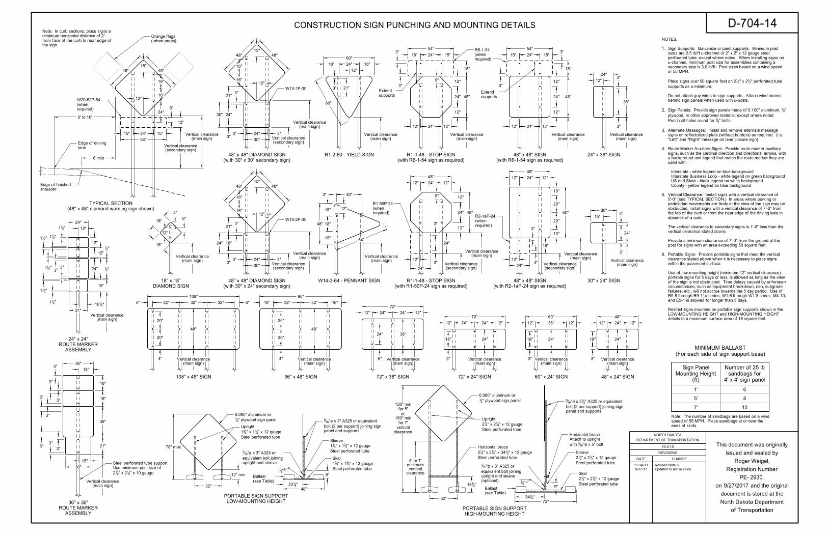
15"
48" 48"
16"
16"
12"
6' min
shoulder
Edge of finished
lane
Edge of driving
6' to 16'
(secondary sign)Vertical clearance
(main sign)Vertical clearance
15"
48" 48"
16"
16"
18"
18"
6"
12"
4"
(urban areas)
Orange flags
3" 21"
60"
60"
24"
12"
12"
12"
15" 15"24"3"
3"
18"
54"
48"
12"
24"
12"
12" 12"24"
9"
12" 24" 12"
48"
12"
24"
18"
3"
3"
10"
20"
20"
10"
60"15"
30"3"
3"
24"
16"
16"
48"
15"
48"
12"
W16-2P-30
24"
30"
3"3"
3"
24"
3"
21"
18"
supports
Extend
48"
15"
15"
18"
30"3"
12"
24"15"
54"
15"
6"24"
24"
30"
3"3"
30"
3"
21"
24"
3"
48"
24" 12"12"
12"
24"
12"
48"
9"
3"
3"
24"
24"
54"
15" 15"24"3"
3"
18"
12"
24"
12"
48"supports
Extend
64"
24"12" 12"
6" 6"32"32"32"
108"
48"
16" 16"
96"
32"32"
12" 12"
72"
36"
24"24"
12" 12"
72"
24"24"
24"
12" 12"
60"
36" 12" 12"
48"
24"
"211
"211
"211
"21
12"
12"
"211
3"3" 24" "2
1
15"
"211
"211
12"
24"
"2110
21"
21"
36"
18"
18"
36"
18"3"
3"
3"
3"
6"
6"3"
3"
30"
15"
(48" x 48" diamond warning sign shown)
TYPICAL SECTION
R1-2-60 - YIELD SIGN
30" x 24" SIGN
(with R6-1-54 sign as required)
R1-1-48 - STOP SIGN
(with R6-1-54 sign as required)
48" x 48" SIGN
W14-3-64 - PENNANT SIGN
12"
(with 30" x 24" secondary sign)
48" x 48" DIAMOND SIGN
(with 30" x 30" secondary sign)
48" x 48" DIAMOND SIGN
DIAMOND SIGN
18" x 18"
108" x 48" SIGN 96" x 48" SIGN 72" x 36" SIGN 72" x 24" SIGN 60" x 24" SIGN 48" x 24" SIGN
18" 18"
24"3"
3"
36"
12"
24" x 36" SIGN
ASSEMBLY
ROUTE MARKER
24" x 24"
ASSEMBLY
ROUTE MARKER
36" x 36"
"4334
(secondary sign)Vertical clearance
(main sign)Vertical clearance
(main sign)Vertical clearance
W13-1P-30
(main sign)Vertical clearance (main sign)
Vertical clearance
(main sign)Vertical clearance
(main sign)Vertical clearance
(main sign)Vertical clearance
(main sign)Vertical clearance
(secondary sign)Vertical clearance
(main sign)Vertical clearance
(secondary sign)Vertical clearance (main sign)
Vertical clearance
(secondary sign)Vertical clearance
3"
24"
6"4"
20"
20"
4"
20"
20"
18"
(main sign)Vertical clearance
(main sign)Vertical clearance
(main sign)Vertical clearance
(main sign)Vertical clearance
(main sign)Vertical clearance
(main sign)Vertical clearance
(main sign)Vertical clearance
48"
24"
(main sign)Vertical clearance
24"
(main sign)Vertical clearance3"
18"
3"
18"
9""2
118"4
1
" plywood sign panel21
0.080" aluminum or
panel and supports
bolt (2 per support) joining sign
" A325 or equivalent 21"| x 316
5
"| x 5" bolt165with
Attach to upright
Horizontal brace
(ft)
Mounting Height
Sign Panel
4' x 4' sign panel
sandbags for
Number of 25 lb
5'
7' 10
(see Table)
Ballast
8
32"
9"
48"
panel and supports
bolt (2 per support) joining sign
"| x 3" A325 or equivalent 165
"41
(see Table)
Ballast
" plywood sign panel21
0.080" aluminum or
upright and sleeve
equivalent bolt joining
"| x 3" A325 or 165
(optional)
upright and sleeve
equivalent bolt joining
"| x 3" A325 or 165
72"
"8123
61'
HIGH-MOUNTING HEIGHT
PORTABLE SIGN SUPPORT
required)
(when
R6-1-54
required)
(when
W20-52P-54
LOW-MOUNTING HEIGHT
PORTABLE SIGN SUPPORT
" x 10 gauge21" x 22
12
Use minimum post size of
Steel perforated tube support
Steel perforated tube
" x 12 gauge21" x 344
1" x 2412
Horizontal brace
Steel perforated tube
" x 12 gauge21" x 22
12
Sleeve
Steel perforated tube
" x 12 gauge21" x 22
12
Skid
Steel perforated tube
" x 12 gauge43" x 14
31
Sleeve
Steel perforated tube
" x 12 gauge43" x 14
31
Skid
Steel perforated tube
" x 12 gauge43" x 14
31
Upright
(For each side of sign support base)
MINIMUM BALLAST
78" max
12" min
32"
Steel perforated tube
" x 12 gauge41" x 24
12
Upright
clearancevertical
minimum5' or 7'
clearance
vertical
for 7'
150" min
or
for 5'
126" min
the sign.
from face of the curb to near edge of
minimum horizontal distance of 2'
Note: In curb sections, place signs a
ends of skids.
speed of 55 MPH. Place sandbags at or near the
Note: The number of sandbags are based on a wind
details to a maximum surface area of 16 square feet.
LOW-MOUNTING HEIGHT and HIGH-MOUNTING HEIGHT
Restrict signs mounted on portable sign supports shown in the
and E5-1 is allowed for longer than 5 days.
R9-8 through R9-11a series, W1-6 through W1-8 series, M4-10,
failures, etc., will not accrue towards the 5 day period. Use of
circumstances, such as equipment breakdown, rain, subgrade
of the sign is not obstructed. Time delays caused by unforseen
portable signs for 5 days or less, is allowed as long as the view
Use of low-mounting height (minimum 12" vertical clearance)
within the pavement surface.
clearance stated above when it is necessary to place signs
Portable Signs: Provide portable signs that meet the vertical 6.
post for signs with an area exceeding 50 square feet.
Provide a minimum clearance of 7'-0" from the ground at the
vertical clearance stated above.
The vertical clearance to secondary signs is 1'-0" less than the
absence of a curb.
the top of the curb or from the near edge of the driving lane in
obstructed, install signs with a vertical clearance of 7'-0" from
pedestrian movements are likely or the view of the sign may be
5'-0" (see TYPICAL SECTION.) In areas where parking or
Vertical Clearance: Install signs with a vertical clearance of 5.
County - yellow legend on blue background
US and State - black legend on white background
Interstate Business Loop - white legend on green background
Interstate - white legend on blue background
used with:
a background and legend that match the route marker they are
signs, such as the cardinal direction and directional arrows, with
Route Marker Auxiliary Signs: Provide route marker auxiliary 4.
"Left" and "Right" message on lane closure sign)
signs on reflectorized plate (without borders) as required. (i.e.
Alternate Messages: Install and remove alternate message 3.
" bolts.83Punch all holes round for
plywood, or other approved material, except where noted.
" 21Sign Panels: Provide sign panels made of 0.100" aluminum, 2.
behind sign panels when used with u-posts.
Do not attach guy wires to sign supports. Attach wind beams
supports as a minimum.
" perforated tube 21" x 22
1Place signs over 50 square feet on 2
of 55 MPH.
secondary sign is 3.0 lb/ft. Post sizes based on a wind speed
u-channel, minimum post size for assemblies containing a
perforated tube, except where noted. When installing signs on
sizes are 2.5 lb/ft u-channel or 2" x 2" x 12 gauge steel
Sign Supports: Galvanize or paint supports. Minimum post 1.
NOTES:
required)
(when
R1-50P-24
(with R1-50P-24 sign as required)
R1-1-48 - STOP SIGN
required)
(when
R2-1aP-24
(with R2-1aP-24 sign as required)
48" x 48" SIGN
10-4-13
D-704-14
2930
CONSTRUCTION SIGN PUNCHING AND MOUNTING DETAILS
Roger Weigel,
REVISIONS
DATE CHANGE
DEPARTMENT OF TRANSPORTATION
NORTH DAKOTA
of Transportation
North Dakota Department
document is stored at the
on and the original
PE- ,
Registration Number
issued and sealed by
This document was originally
11-14-13 Revised Note 6.
9-27-17 Updated to active voice
9/27/2017
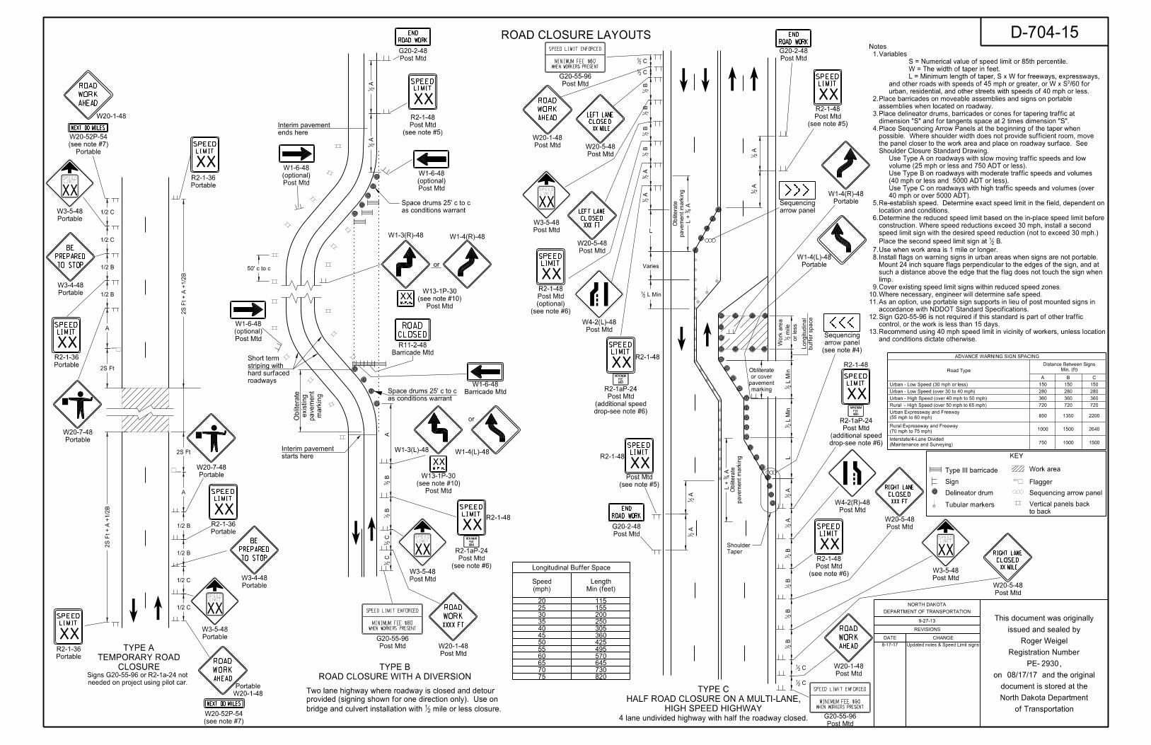
AHEAD
ROAD
WORK
AHEAD
ROAD
WORK
AHEAD
ROAD
WORK
AHEAD
ROAD
WORK
NEXT MILES00
NEXT MILES00
BE
PREPARED
TO STOP
BE
PREPARED
TO STOP
XXXX FT
ROAD
WORK
CLOSED
ROAD
END
ROAD WORK
END
ROAD WORK
END
ROAD WORK
XXX FT
CLOSED
RIGHT LANE
XX MILE
CLOSED
LEFT LANE
XX MILE
CLOSED
RIGHT LANE
XXX FT
CLOSED
LEFT LANE
SPEED LIMIT ENFORCED
MINIMUM FEE $80WHEN WORKERS PRESENT
SPEED LIMIT ENFORCED
MINIMUM FEE $80WHEN WORKERS PRESENT
MINIMUM
FEE
$80
MINIMUM
FEE
$80
MINIMUM
FEE
$80
SPEEDLIMIT
XX
SPEED
XXLIMIT
SPEED
XXLIMIT
SPEED
XXLIMIT
SPEEDLIMIT
XX
SPEED
XXLIMIT
SPEEDLIMIT
XX
SPEED
XXLIMIT
M.P.H.
XX
SPEEDLIMIT
XX
SPEED
XXLIMIT
SPEED
XXLIMIT
SPEED
XXLIMIT
SPEED
XXLIMIT
M.P.H.
XX
SPEED
XXLIMIT
SPEEDLIMIT
XX
SPEED
XXLIMIT
SPEED
XXLIMIT
SPEED LIMIT ENFORCED
MINIMUM FEE $80WHEN WORKERS PRESENT
8-17-17 Updated notes & Speed Limit signs
Portable
(see note #7)
W20-52P-54
Portable
W3-4-48
Portable
W3-4-48
W20-1-48
Portable
W20-1-48
ends here
Interim pavement
roadways
hard surfaced
striping with
Short term
markin
g
pave
ment
existing
Obliterate
starts here
Interim pavement
W1-3(R)-48
or
W1-4(R)-48
W1-3(L)-48 W1-4(L)-48
R2-1-48
R2-1-48
arrow panel
Sequencing
R2-1-48
R2-1-48
(see note #7)
W20-52P-54
CLOSURE
TEMPORARY ROAD
TYPE A
4 lane undivided highway with half the roadway closed.
2S Ft A
21
A2
1
50' c to c
A
C
21
C2
1 B
21
B2
1
A4
3L +
pave
ment
markin
g
Obliterate
C21
C21
A2
1 A
21
B2
1 B
21
B2
1 B
21
L
Varies
L Min21
A2
1 A
21
A4
3L +
pave
ment
markin
g
Obliterate
A
21
A2
1
C21
C21
B2
1 B
21
B2
1 B
21
A2
1 A
21
L L Min
21
L Min
21
or less
mile
21
Work are
a
buffer space
Longitudinal
marking
pavement
or cover
Obliterate
KEY
Type III barricade
Sign
Delineator drum
Work area
Flagger
Sequencing arrow panel
Longitudinal Buffer Space
(mph)
Speed
Min (feet)
Length
202530354045505560657075
115155200250305360425495570645730820
Portable
W20-7-48
Portable
W20-7-48
(see note #4)
arrow panel
Sequencing
to back
Vertical panels backTubular markers
ROAD CLOSURE WITH A DIVERSION
TYPE B
HIGH SPEED HIGHWAY
HALF ROAD CLOSURE ON A MULTI-LANE,
TYPE C
Taper
Shoulder
Portable
W1-4(R)-48
2S Ft
1/2 C
1/2 C
Portable
R2-1-36
Portable
W3-5-48
2S Ft + A +
1/2
B
2S Ft + A +
1/2
B
Portable
R2-1-36
Portable
R2-1-36
1/2 C
1/2 C
A
1/2 B
1/2 B
A
1/2 B
1/2 B
Portable
W3-5-48
Portable
R2-1-36
needed on project using pilot car.
Signs G20-55-96 or R2-1a-24 not
(see note #6)
Post Mtd
R2-1-48
Post Mtd
W20-5-48
Post Mtd
W4-2(R)-48
Portable
W1-4(L)-48
(see note #5)
Post Mtd
R2-1-48
Post Mtd
G20-2-48
Post Mtd
W20-1-48
Post Mtd
G20-55-96
Post Mtd
W20-5-48
Post Mtd
W20-5-48
(see note #6)
(optional)
Post Mtd
R2-1-48
Post Mtd
W4-2(L)-48
Post Mtd
G20-2-48
Post Mtd
(optional)
W1-6-48
Barricade Mtd
W1-6-48
Barricade Mtd
R11-2-48
(see note #5)
Post Mtd
Post Mtd
W3-5-48
Post Mtd
W20-5-48
Post Mtd
W20-1-48
Post Mtd
W20-1-48Post Mtd
G20-55-96
Post Mtd
W3-5-48
(see note #5)
Post Mtd
R2-1-48
Post Mtd
(optional)
W1-6-48
Post Mtd
(optional)
W1-6-48
Post Mtd
G20-2-48
Post Mtd
G20-55-96
or
Post Mtd
W3-5-48
as conditions warrant
Space drums 25' c to c
as conditions warrant
Space drums 25' c to c
mile or less closure.21bridge and culvert installation with
provided (signing shown for one direction only). Use on
Two lane highway where roadway is closed and detour
and conditions dictate otherwise.
Recommend using 40 mph speed limit in vicinity of workers, unless location 13.
control, or the work is less than 15 days.
Sign G20-55-96 is not required if this standard is part of other traffic 12.
accordance with NDDOT Standard Specifications.
As an option, use portable sign supports in lieu of post mounted signs in 11.
Where necessary, engineer will determine safe speed.10.
Cover existing speed limit signs within reduced speed zones. 9.
limp.
such a distance above the edge that the flag does not touch the sign when
Mount 24 inch square flags perpendicular to the edges of the sign, and at
Install flags on warning signs in urban areas when signs are not portable. 8.
Use when work area is 1 mile or longer. 7.
B. 21Place the second speed limit sign at
speed limit sign with the desired speed reduction (not to exceed 30 mph.)
construction. Where speed reductions exceed 30 mph, install a second
Determine the reduced speed limit based on the in-place speed limit before 6.
location and conditions.
Re-establish speed. Determine exact speed limit in the field, dependent on 5.
40 mph or over 5000 ADT).
Use Type C on roadways with high traffic speeds and volumes (over
(40 mph or less and 5000 ADT or less).
Use Type B on roadways with moderate traffic speeds and volumes
volume (25 mph or less and 750 ADT or less).
Use Type A on roadways with slow moving traffic speeds and low
Shoulder Closure Standard Drawing.
the panel closer to the work area and place on roadway surface. See
possible. Where shoulder width does not provide sufficient room, move
Place Sequencing Arrow Panels at the beginning of the taper when 4.
dimension "S" and for tangents space at 2 times dimension "S".
Place delineator drums, barricades or cones for tapering traffic at 3.
assemblies when located on roadway.
Place barricades on moveable assemblies and signs on portable 2.
urban, residential, and other streets with speeds of 40 mph or less.
and other roads with speeds of 45 mph or greater, or W x SÔ/60 for
L = Minimum length of taper, S x W for freeways, expressways,
W = The width of taper in feet.
S = Numerical value of speed limit or 85th percentile.
Variables 1.
Notes
(see note #6)
Post Mtd
R2-1aP-24
drop-see note #6)
(additional speed
Post Mtd
R2-1aP-24
drop-see note #6)
(additional speed
Post Mtd
R2-1aP-24
Post Mtd
(see note #10)
W13-1P-30
Post Mtd
(see note #10)
W13-1P-30
REVISIONS
DATE CHANGE
DEPARTMENT OF TRANSPORTATION
NORTH DAKOTA
of Transportation
North Dakota Department
document is stored at the
on and the original
PE- ,
Registration Number
issued and sealed by
This document was originally9-27-13
D-704-15
08/17/17
2930
ADVANCE WARNING SIGN SPACING
Min. (ft)
Distance Between Signs
Road Type
A B C
150 150 150
280 280 280
360 360 360
720 720 720
850 1350 2200
1000 1500 2640
750 1000 1500
Urban - Low Speed (30 mph or less)
Urban - High Speed (over 40 mph to 50 mph)
Rural - High Speed (over 50 mph to 65 mph)
(55 mph to 60 mph)
Urban Expressway and Freeway
(70 mph to 75 mph)
Rural Expressway and Freeway
(Maintenance and Surveying)
Interstate/4-Lane Divided
Urban - Low Speed (over 30 to 40 mph)
ROAD CLOSURE LAYOUTS
Roger Weigel
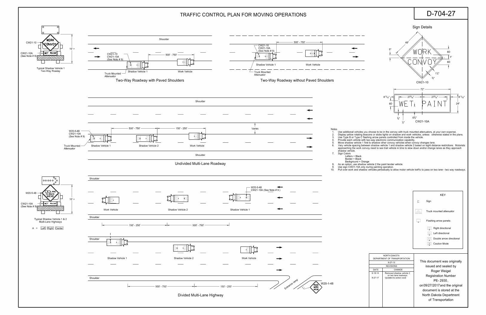
PAINTWET
CONVOY
WORK
A LANE
CLOSED
AHEAD
WET PAINT
AHEAD
ROAD
WORK
PAINTWET
CONVOY
WORK
24"
72"
"16527 "16
527 "16118
"436
"21
"43
8D
"16118
5"
48"
6"
"411
"43
8D
8D
Shoulder
Shoulder
Shoulder
Shoulder
Work Vehicle
Work Vehicle
10' +
W20-5-48
(See Note # 9)
CW21-10A
Multi-Lane Highways
Typical Shadow Vehicle 1 & 2
Shadow Vehicle 1 Shadow Vehicle 2
Shadow Vehicle 1Shadow Vehicle 2
Entra
nce ra
mp
W20-1-48
150' - 250' 500' - 750'
500' - 750' 150' - 250'
Divided Multi-Lane Highway
CW21-10
CW21-10A
Right directional
Left directional
Double arrow directional
Caution Mode
Sign
CenterLeft RightA =
Sign Details
KEY
Shoulder
Work Vehicle
Work Vehicle
Shadow Vehicle 1
Shadow Vehicle 1
Attenuator
Truck Mounted
Two-Way Roadway with Paved Shoulders Two-Way Roadway without Paved Shoulders
Attenuator
Truck Mounted
500' - 750'
500' - 750'
(See Note # 9)
CW21-10A
CW21-10
(See Note # 9)
CW21-10A
CW21-10
Varies
Shoulder
Shoulder
Work Vehicle
10' +
CW21-10
Shadow Vehicle 1 Shadow Vehicle 2
Attenuator
Truck Mounted
Undivided Multi-Lane Roadway
500' - 750' 150' - 250'
(See Note # 9)
CW21-10A
(See Note # 9)
CW21-10A
W20-5-48
CW21-10A (See Note # 9 )
W20-5-48
Two-Way Roaday
Typical Shadow Vehicle 1
Flashing arrow panels:
Truck mounted attenuator
Pull over work and shadow vehicles periodically to allow motor vehicle traffic to pass on two lane - two way roadways.10.
Use sign CW21-10A only during painting operation. 9.
As an option, use shadow vehicle 2 the paint tender vehicle. 8.
Background = Orange
Border = Black
Letters = Black
Sign Colors 7.
shadow vehicle.
approaching the work convoy need to see trail vehicle in time to slow down and/or change lanes as they approach
Vary vehicle spacing between shadow vehicle 1 and shadow vehicle 2 based on sight distance restrictions. Motorists 6.
Move shadow vehicle 1 first to shadow other convoy vehicles when convoy changes lane. 5.
Provide each vehicle with two-way electronic communication capability. 4.
Use Type B or Type C flashing arrow panels controlled from inside the vehicle. 3.
otherwise stated in the plans.Display yellow rotating beacons or stobe lights on shadow and work vehicles, unless 2.
Use additional vehicles you choose to be in the convoy with truck mounted attenuators, at your own expense. 1.
Notes
D-704-27
2930
TRAFFIC CONTROL PLAN FOR MOVING OPERATIONS
9-27-13
Roger Weigel
on two lane roadways
Removed shadow vehicle 2
REVISIONS
DATE CHANGE
DEPARTMENT OF TRANSPORTATION
NORTH DAKOTA
of Transportation
North Dakota Department
document is stored at the
on and the original
PE- ,
Registration Number
issued and sealed by
This document was originally
6-18-14
9-27-17 Updated to active voice
09/27/2017

Wheel track
Wheel track
R R
CR
OSSI
NG
RO
AD
RAIL
2'-10"
"412'-10
"216'-4
"4114'-10
"834'-4
5'-9"
18'-0"
45°
10°
Curb face
of Roadway`
2'x6', 2'x8', 2'x10' or 2'x12' white line
30'
10'
Edge line
Edge line
30-40 mph
0-25 mph
and above
45 mph
8"
8"
12" 25'
15'
5'
Chevron WidthLimit
Speed
70 mph
65 mph
60 mph
55 mph
50 mph
45 mph
40 mph
35 mph
30 mph
25 mph
20 mph min. 100 ft
min. 100 ft
min. 100 ft
min. 100 ft
125 ft
175 ft
250 ft
325 ft
400 ft
475 ft
550 ft
Distance
Advance
Percentile Speed
Posted or 85th
for Railroad Warning Signs
Advance Placement Distance
45° to Traffic
Chevron Spacing
6'-4"
3'-0"
8"
2'-4"
5'-4"
1'-8"
3'-8"
4"
8"
1'-0"
8'-0"
=3'-4"R
=2'-4"R
1'-8"
16 S. F.
9'-6"
5'-0"
4'-6"
1'-0"
3'-4"
1'-2" 1'-0"
12 S. F. 41 S. F.
16" 7" 16" 7" 15" 1" 16"
8'-0"
16"
42"
22"
16"
4"
4"
4"
4" 4"
4"
4"
4"
6'-6"
22 S. F.
4"
4"4"4"
4"
4"
4"
4"16" 16"
2"16"
5"16"
16"
4"
8"
16"
8"
16"
16"
12"
8'-0"
6'-3"
6"
22 S. F.
16"4"
16"4"
16"4"
16"4"
16"4"
16"
4"
4"
4"
4"
4"4"
4" 4"
16"
4"
6"
16"
8"
16"
4"
18"
8"
34.5 S. F.
16"4"
16"4"
16"4"
16"4"
16"4"4"4"
16"4"
16"
16"
8"
4"
16"
16"
4"
16"
8"
4"
4"
4"
4"
4"
4" 4"
4" 4"
4"
4"
4"
4"
4"
4"
4"
4" 8"
46 S. F.
8'-0"
12'-0"9'-8"
8'-0"
11'-8"
3'-0"
8"
2'-8"
4"
4"
8"
5'-4" 1'-0" 5'-4"
=3'-4"R
=2'-4"R
1'-8"
8'-4"
2'-8"
3'-8"
2'-0"
2'-4"
1'-8"
2'-4"
29 S. F.
6'-0"
"431'-0
"431'-9
"431'-0
"432'-0
1'-1"
"413
4 S. F.
8"
R=3'-4"
1'-0"
1'-0"
7'-6"
3'-0"
8"
3'-4"1'-2"
4"
8'-0"
7'-5"
5'-4"
3'-8"
1'-8"
2'-4"
1'-8"
12'-9"
5'-0"
7'-9"=2'-4"R
27 S. F.
gate, if present
Stop line 8' fromstripe
barrier
4" yellow
` of driving lane
W10-1
3 Bands (12' lane) 72 S.F.
Railroad cross & 2 R's 60.5 S.F.
R15-1
Drawing D-754-81See Standard
10'
24'
60'
20' 16'
See Advanced Placement Distance table at right
2'
3.3' 6.6'16"
6' 1.6'
2'
20' max19' min
15'
Bands at right angles to pavement
4" yellow `
between lines
4" space
2'
24"
24"
24"
24"
24"
24"
24"
24"
30"
6" min to 15" max
12" min to 30" max
12" min to 30" max
30" max
unless noted otherwise.
See plans for correct message. Use white pavement markings
individual R X R symbols in each approach lane.
extend the transverse bands across all approach lanes, and use
operation on the approach to a crossing. On multi-lane roads,
Mark a three lane roadway with a centerline for two-lane approach
Notes:
20^ from edge of roadway.
Note: Rotate merge arrow
2930
REVISIONS
DATE CHANGE
DEPARTMENT OF TRANSPORTATION
NORTH DAKOTA
of Transportation
North Dakota Department
document is stored at the
on and the original
PE- ,
Registration Number
issued and sealed by
This document was originally
Continental Crosswalk Detail
Centerline Pavement Marking Skip Spacing Detail
Chevron Crosshatching Table
D-762-1Pavement Marking Message Details
12-6-11
Roger Weigel,
10-17-2017
Updated to active voice.10-17-17
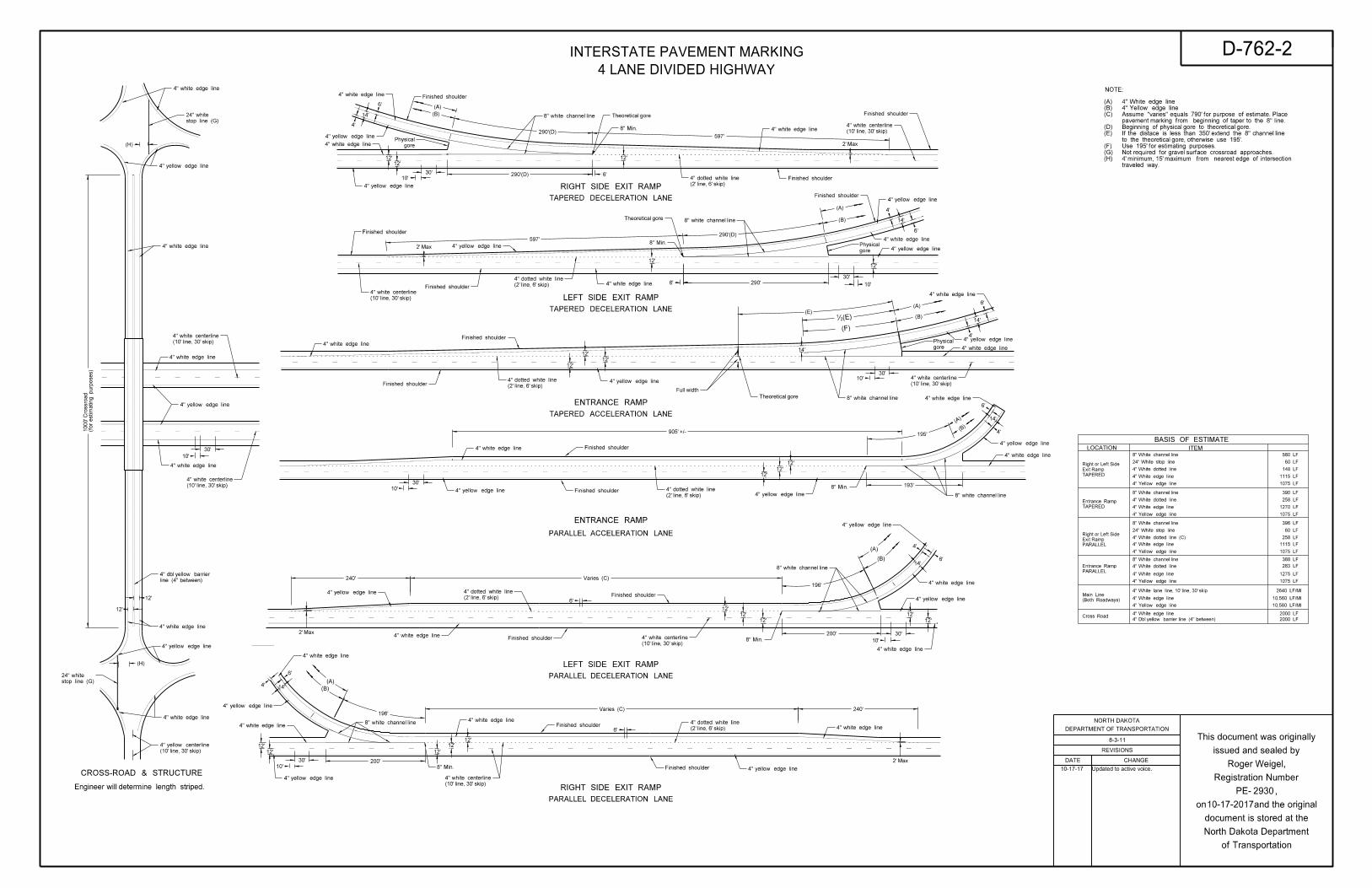
4" white edge line
4" white edge line
4" white edge line
4" white edge line
4" white edge line
4" white edge line
4" white edge line
4" white edge line
4" white edge line
4" white edge line
4" white edge line
4" white edge line
4" white edge line
4" white edge line
4" white edge line
4" white edge line
4" white edge line
4" white edge line
4" yellow edge line
4" white edge line
4" yellow edge line
4" yellow edge line
4" yellow edge line
4" yellow edge line
4" yellow edge line4" yellow edge line
4" yellow edge line
4" yellow edge line
4" yellow edge line
4" yellow edge line
4" yellow edge line
4" yellow edge line
4" yellow edge line
4" yellow edge line
Finished shoulder
Finished shoulder
Finished shoulder
Finished shoulder
Finished shoulder
Finished shoulder
Finished shoulder
Finished shoulder
Finished shoulder
Finished shoulder
Finished shoulder
8" white channel line
8" white channel line
line (4" between)
4" dbl yellow barrier
(10' line, 30' skip)
4" white centerline
(10' line, 30' skip)
4" white centerline
(10' line, 30' skip)
4" white centerline
(10' line, 30' skip)
4" white centerline
(10' line, 30' skip)
4" white centerline
(10' line, 30' skip)
4" yellow centerline
200'
240'
200'
12'
6'
240'
10'
597'
12'
6'
12'
6'
6'
14'
4'
12'
30'
10'
597'
2' Max
4'
14'
6'
12'
10'
30'
2' Max
14'
6'
4'195'
193'
12'
12'
12'
30'
10'
(A)
(B)
(A)
(B)
4' 14'
12'
12'
30'
10'
12'
6'
30'
10'
12'
12'
6'
4'
14'
12'
12'
30'
905' +/-
6'
Varies (C)4" yellow edge line
12'
(B)
(A)
Varies (C)
12'
12'
12'
12'
8" white channel line
8" white channel line
8" white channel line
2' Max
8" Min.
8" Min.
8" Min.
8" Min.
8" Min.
(for esti
mating purp
oses)
1000' Crossro
ad
2' Max
(2' line, 6' skip)
4" dotted white line
stop line (G)
24" white
(H)
stop line (G)
24" white
(H)
290'(D)
gore
Physical
Theoretical gore
290'(D)
Finished shoulder
Theoretical gore
gore
Physical
290'(D)
290'(2' line, 6' skip)
4" dotted white line
4" yellow edge line
4" white edge line
(10' line, 30' skip)
4" white centerline
12'
12'
12'
14'
10'30'
6'
14'
4'
(B)
4" white edge line
(E)
gore
Physical 4" yellow edge line
Theoretical gore
4" white edge line
4" white edge line
4" yellow edge lineFinished shoulder
Finished shoulder
Full width(2' line, 6' skip)
4" dotted white line
(A)
4" white edge line
•(E)
(F)
(2' line, 6' skip)
4" dotted white line
(2' line, 6' skip)
4" dotted white line
(2' line, 6' skip)
4" dotted white line
8" white channel line
(B)
(A)
196'
(A)
(B)
196'
(10' line, 30' skip)
4" white centerline
Updated to active voice.10-17-17
4" White lane line, 10' line, 30' skip
4" White edge line
4" Yellow edge line
LOCATION ITEM
BASIS OF ESTIMATE
TAPERED
Entrance Ramp
8" White channel line
24" White stop line
4" White dotted line
4" Yellow edge line
4" White edge line
8" White channel line
4" Yellow edge line
4" White edge line
8" White channel line
24" White stop line
4" Yellow edge line
4" White edge line
8" White channel line
4" Yellow edge line
4" White edge line
Cross Road4" White edge line
4" Dbl yellow barrier line (4" between)
4" White dotted line (C)
NOTE:
PARALLEL
Entrance Ramp
PARALLEL
Exit Ramp
Right or Left Side
TAPERED
Exit Ramp
Right or Left Side
(Both Roadways)
Main Line
580 LF
60 LF
148 LF
1115 LF
1075 LF
390 LF
258 LF
1270 LF
1075 LF
396 LF
60 LF
258 LF
1115 LF
1075 LF
388 LF
1275 LF
1075 LF
2000 LF
2000 LF
2640 LF/MI
10,560 LF/MI
10,560 LF/MI
4" White dotted line
4" White dotted line 283 LF
traveled way.
4' minimum, 15' maximum from nearest edge of intersection (H)
Not required for gravel surface crossroad approaches.(G)
Use 195' for estimating purposes.(F)
to the theoretical gore, otherwise use 195'.
If the distace is less than 350' extend the 8" channel line (E)
Beginning of physical gore to theoretical gore.(D)
pavement marking from beginning of taper to the 8" line.
Assume "varies" equals 790' for purpose of estimate. Place(C)
4" Yellow edge line(B)
4" White edge line(A)
RIGHT SIDE EXIT RAMP
TAPERED DECELERATION LANE
LEFT SIDE EXIT RAMP
TAPERED DECELERATION LANE
ENTRANCE RAMP
TAPERED ACCELERATION LANE
ENTRANCE RAMP
PARALLEL ACCELERATION LANE
LEFT SIDE EXIT RAMP
PARALLEL DECELERATION LANE
RIGHT SIDE EXIT RAMP
PARALLEL DECELERATION LANE
CROSS-ROAD & STRUCTURE
REVISIONS
DATE CHANGE
DEPARTMENT OF TRANSPORTATION
NORTH DAKOTA
of Transportation
North Dakota Department
document is stored at the
on and the original
PE- ,
Registration Number
issued and sealed by
This document was originally
2930
D-762-2
Roger Weigel,
8-3-11
INTERSTATE PAVEMENT MARKING
4 LANE DIVIDED HIGHWAY
Engineer will determine length striped.
10-17-2017
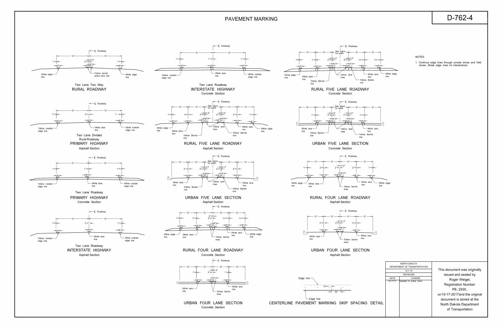
` Roadway
` Roadway
` Roadway
` Roadway
` Roadway` Roadway
` Roadway
` Roadway
` Roadway
` Roadway
` Roadway
` Roadway
` Roadway
and/or lane line
Yellow barrier
edge line
Yellow medianline
White lane
line
White lane
line
White lane
edge line
White outside
edge line
White outside
edge line
White outside
edge line
Yellow median
edge line
Yellow median
edge line
Yellow median line
White lane
line
White laneline
White lane
line
White lane
line
White lane
line
White lane line
White lane
line
White lane
line
White lane
line
White laneline
White lane
line
White laneline
White lane
line
White lane
line
White lane
line
White lane line
White lane
edge line
White outside
line
White edge
line
White edge
line
White edge
line
White edge
line
White edge
line
White edge
line
White edge
line
White edge
lines
Yellow barrier
lines
Yellow barrier
lines
Yellow barrier
lines
Yellow barrier
lines
Yellow lane
lines
Yellow lane
lines
Yellow lane
lines
Yellow lane
12' 12'
2"
4"4"
2"
4"
1"
4"
1"
4"
2"
12' 12'
1"
4"4"
1"
12' 12'
1"1" 1"
4"4"4"
12' 12'
1"
4"4"
1"
4"
2"
12' 12'
1"
4"4"4"
1"1"
12' 12' 12' 12'
2"2"
2" 2"2"
2"1" 1"
4" 4"4"
4"4"
4"
4" 4"
12' 12' 12' 12'
4"
2" 2"2"
2"2"
2"
4"4"
4"4"
4"
12' 12' 12' 12'
4" 4" 4"4"
4" 4"
2"1" 1"2"
12' 12' 12' 12'
1" 1"2"
2"
4" 4"4"
4"
12'12'12'12'
12'12'12'12'
12' 12' 12' 12'
12' 12' 12' 12'
1" 1"
1" 1"
2"2"
2"2" 2"
2"
4" 4" 4"4"
4"4"
4" 4"
4" 4"4"
4"4"
4"
4" 4" 4"4"
4" 4"
4" 4"4"
4"
1" 1"2" 2"2"
2"
2"2"
2"2"
2"
1•" 1•"
1•"1•"2"
for widthSee plans
for widthSee plans
for widthSee plans
for widthSee plans
line
White edge
line
White edge
line
Yellow Barrier line
Yellow Barrier
line
Yellow Barrier
line
Yellow Barrier
line
Yellow Barrierline
Yellow Barrier
line
Yellow Barrier
line
Yellow Barrier
30'
10'
drives. Break edge lines for intersections.
1. Continue edge lines through private drives and field
NOTES:
10-17-17 Updated to active voice.
Two Lane Two Way
RURAL ROADWAY
PRIMARY HIGHWAY
Asphalt Section
Two Lane Divided
Rural Roadway
PRIMARY HIGHWAY
INTERSTATE HIGHWAY RURAL FOUR LANE ROADWAY
URBAN FIVE LANE SECTION
RURAL FIVE LANE ROADWAY
INTERSTATE HIGHWAY
URBAN FOUR LANE SECTION
URBAN FOUR LANE SECTION
RURAL FOUR LANE ROADWAY
URBAN FIVE LANE SECTION
RURAL FIVE LANE ROADWAY
Asphalt Section
Asphalt Section
Concrete Section
Concrete Section
Concrete Section
Concrete Section
Asphalt Section
Asphalt Section
Concrete Section
Two Lane Roadway
Asphalt Section
Two Lane Roadway
Concrete Section
Two Lane Roadway
Edge line
Edge line
REVISIONS
DATE CHANGE
DEPARTMENT OF TRANSPORTATION
NORTH DAKOTA
of Transportation
North Dakota Department
document is stored at the
on and the original
PE- ,
Registration Number
issued and sealed by
This document was originally
2930
PAVEMENT MARKING D-762-4
CENTERLINE PAVEMENT MARKING SKIP SPACING DETAIL
Roger Weigel,
12-1-10
10-17-2017
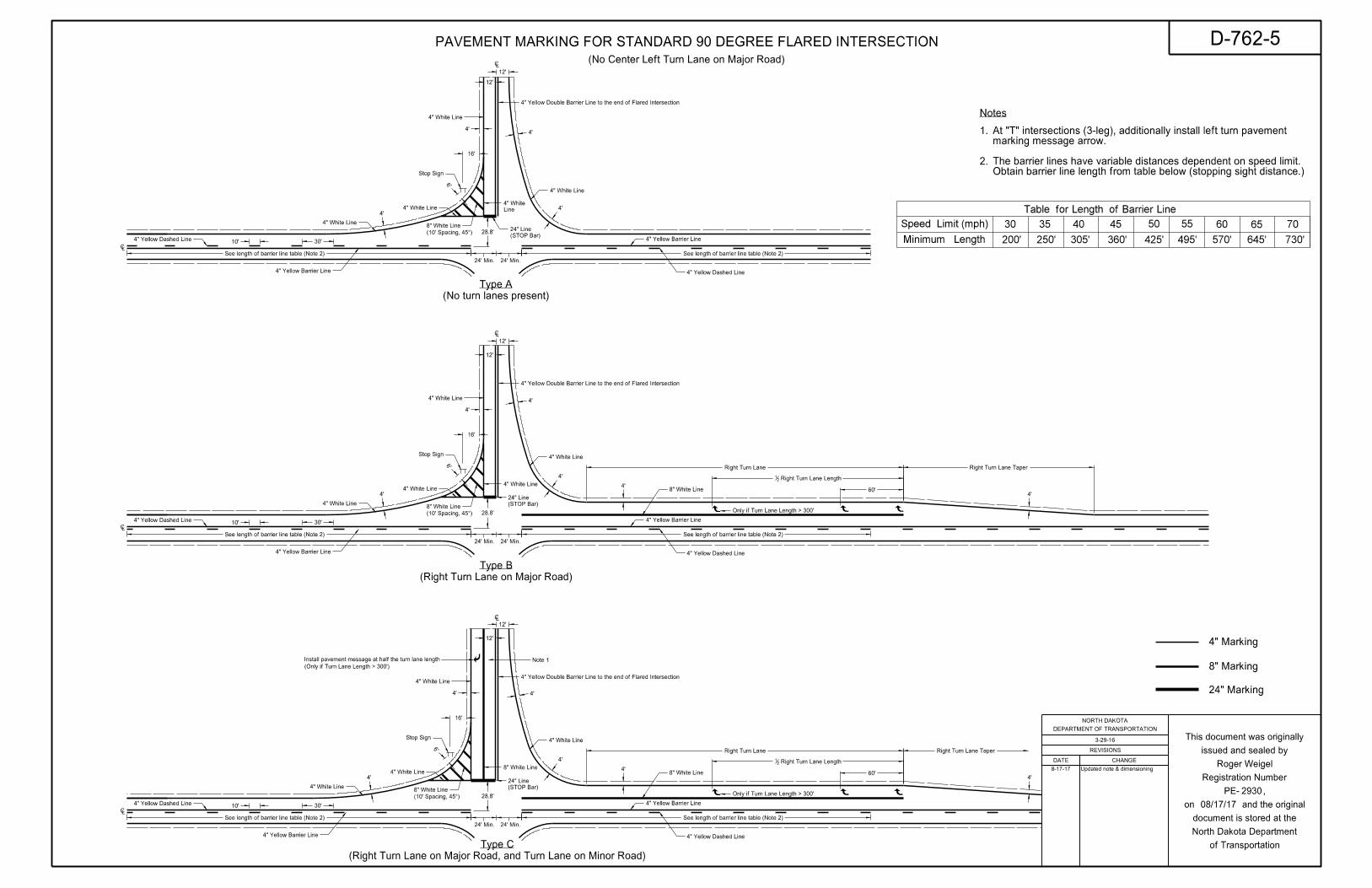
(No turn lanes present)
Type A
(Right Turn Lane on Major Road)
Type B
(No Center Left Turn Lane on Major Road)
(Right Turn Lane on Major Road, and Turn Lane on Minor Road)
Type C
4" Marking
8" Marking
24" Marking
4'
12'
12'
4'
4'4'
(STOP Bar)
24" Line28.8'
30'10'
4" Yellow Barrier Line
4" Yellow Barrier Line
4" Yellow Dashed Line
4" Yellow Dashed Line
24' Min. 24' Min.
See length of barrier line table (Note 2) See length of barrier line table (Note 2)
4'
12'
12'
4'
4'
4'
28.8'
30'10'
4" Yellow Barrier Line
4" Yellow Barrier Line
4" Yellow Dashed Line
4" Yellow Dashed Line
24' Min. 24' Min.
See length of barrier line table (Note 2) See length of barrier line table (Note 2)
(STOP Bar)
24" Line
4'
4'8" White Line
4" White Line
4" White Line
4" White Line
4" White Line
4" White Line
4" White Line
1.
2.
Notes
40 50 60 65 70554530
200'
35
250' 305' 360' 425' 495' 570' 645' 730'
4'
12'
12'
4'
4'
4'
28.8'
30'10'
4" Yellow Barrier Line
4" Yellow Barrier Line
4" Yellow Dashed Line
4" Yellow Dashed Line
24' Min. 24' Min.
See length of barrier line table (Note 2) See length of barrier line table (Note 2)
(STOP Bar)
24" Line
4'
4'8" White Line
4" White Line
4" White Line
4" White Line
Note 1
`
`
`
`
`
`
Right Turn Lane
Right Turn Lane Length21
Right Turn Lane Taper
Right Turn Lane Right Turn Lane Taper
Right Turn Lane Length21
16'
4" White Line
16'
4" White Line
4" White Line
16'
Install pavement message at half the turn lane length
(10' Spacing, 45^)
8" White Line
(10' Spacing, 45^)
8" White Line
(10' Spacing, 45^)
8" White Line
8" White Line
4" White Line
Line
4" White
4" Yellow Double Barrier Line to the end of Flared Intersection
4" Yellow Double Barrier Line to the end of Flared Intersection
4" Yellow Double Barrier Line to the end of Flared Intersection
Speed Limit (mph)
Minimum Length
Table for Length of Barrier Line
(Only if Turn Lane Length > 300')
Only if Turn Lane Length > 300'
Only if Turn Lane Length > 300'
Stop Sign
6'
Stop Sign
6'
Stop Sign
6'
60'
60'
Obtain barrier line length from table below (stopping sight distance.)The barrier lines have variable distances dependent on speed limit.
marking message arrow.At "T" intersections (3-leg), additionally install left turn pavement
8-17-17 Updated note & dimensioning
08/17/17
2930
REVISIONS
DATE CHANGE
DEPARTMENT OF TRANSPORTATION
NORTH DAKOTA
of Transportation
North Dakota Department
document is stored at the
on and the original
PE- ,
Registration Number
issued and sealed by
This document was originally
D-762-5
3-29-16
PAVEMENT MARKING FOR STANDARD 90 DEGREE FLARED INTERSECTION
Roger Weigel

4" Marking
8" Marking
24" Marking
4'
12'
12'
4'
4'4'
4" Line
(STOP Bar)
24" Line28.8'
24' Min. 24' Min.
4'
12'
12'
4'
4'
4'
(10' Spacing, 45^)
28.8'
(STOP Bar)
24" Line
4'
4'8" White Line
4" White Line
4" White Line
4" White Line
4" White Line
4" White Line
4" White Line
1.
Notes
4'
12'
12'
4'
4'
28.8'
(STOP Bar)
24" Line
Turn Lane
Turn Lane Length21
4'8" White Line
4" White Line
4" White Line
4" White Line
Turn Lane Taper
24' Min. 24' Min.
4'
24' Min. 24' Min.
4" Yellow Double Barrier
4" Yellow Double Barrier
(Center Left Turn Lane on Major Road)
Type D
(Center Left & Right Turn Lane on Major Road)
Type E
(Center Left & Right Turn Lane on Major road, and Turn Lane on Minor Road)
Type F
8" White Line
8" White Line4" White Line
4" White Line
`
`
`
`
`
`
(Center Left Turn Lane on Major Road)
Right Turn Lane Right Turn Lane Taper
Left Turn Lane Left Turn Lane Taper
Left Turn Lane Length21
Right Turn Lane Length21
4" Yellow Double Barrier Line to the end of Flared Intersection
Left Turn Lane
Left Turn Lane Length21
60'
Left Turn Lane Taper
Left Turn Lane
Left Turn Lane Length21
60'
4" White Line
4" White Line
4" White Line
4'
Note 1Install pavement message at half the turn lane length
4" White Line
8" White Line
8" White Line
(10' Spacing, 45^)
8" White Line
(10' Spacing, 45^)
8" White Line
8" White Line4" White Line
8" White Line
4" Yellow Double Barrier
4" Yellow Double Barrier
4" Yellow Double Barrier
4" Yellow Double Barrier
4" Yellow Double Barrier Line to the end of Flared Intersection
4" Yellow Double Barrier Line to the end of Flared Intersection pavement marking message arrow.At "T" intersections (3-leg), additionally install left turn
16'
Stop Sign
6'
16'
Stop Sign
6'
16'
Stop Sign
6'
(Only if Turn Lane Length > 300')
Only if Turn Lane Length > 300'
Only if Turn Lane Length > 300'
Only if Turn Lane Length > 300'
Only if Turn Lane Length > 300'
Only if Turn Lane Length > 300'
60'
60'
60'
08/17/17
2930
REVISIONS
DATE CHANGE
DEPARTMENT OF TRANSPORTATION
NORTH DAKOTA
of Transportation
North Dakota Department
document is stored at the
on and the original
PE- ,
Registration Number
issued and sealed by
This document was originally
D-762-6
3-29-16
PAVEMENT MARKING FOR STANDARD 90 DEGREE FLARED INTERSECTION
Roger WeigelUpdated dimensioning8-17-17