Embed Size (px)
Citation preview
1
SECTION I. —INTRODUCTORY
1. Scope of Chapter.— This chapter deals with traversing as carried out
in Geospatial Data Centre for surveys on scales from 1:1,000 to 1:100,000.
For town surveys and other large scale surveys the procedure has to be
modified and special precautions taken, and these are not dealt with in this
chapter.
Every supervising officer will do well to read the following :-
(a) The theory of traversing set out in the introduction to Traverse Tables, by
Major – General J.T.Boileau, F.R.S.
(b) The portion dealing with propagation of error in measurements with steel
tape, and propagation of error in traversing in chapter IV of Vol.I of Plane
and Geodetic Surveying by David Clark, 5th
Edition 1958.
2. Purposes of traversing.— In a Geospatial Data Centre traverse may be
required for the following purposes :-
(a) to fix points for plane-tabling and air survey in areas unsuitable for
triangulation and G.P.S, survey.
(b) to fix the course of a road, river, or boundary with accuracy greater than can
be done by plane-table,
(c) to fix the relative positions of boundary pillars in numerical terms that can be
recorded for their future identification.
(d) to fix the GCP‘s for georeferencing of satellite imageries and aerial
photographs.
Traversing is a more laborious but at the same time an equally accurate
method of fixing points as compared to triangulation, and, therefore, except for
reasons under (b) and (c) , would only be resorted to in flat ground where
buildings, trees, high grass or haze prevent distant vision. In such a country
traversing either supplements or replaces triangulation.
In exceptional cases traverses may replace triangulation, but the traversing
must then be of a specially high accuracy such as described later in subsequent
para.
3. Definitions.— A traverse is the course taken when measuring a
connected series of straight lines, each joining two points on the ground. These
2
points are called traverse stations and the straight line between two traverse
stations is called a traverse leg.
Traverses are classified as closed and unclosed. A traverse which either
emanates from a known station and returns to the same station, or runs between
two known stations, is called a closed traverse; in the former case it is also called
a traverse circuit. A traverse which neither returns to its starting point nor begins
and ends at known stations is called an open traverse or unclosed traverse.
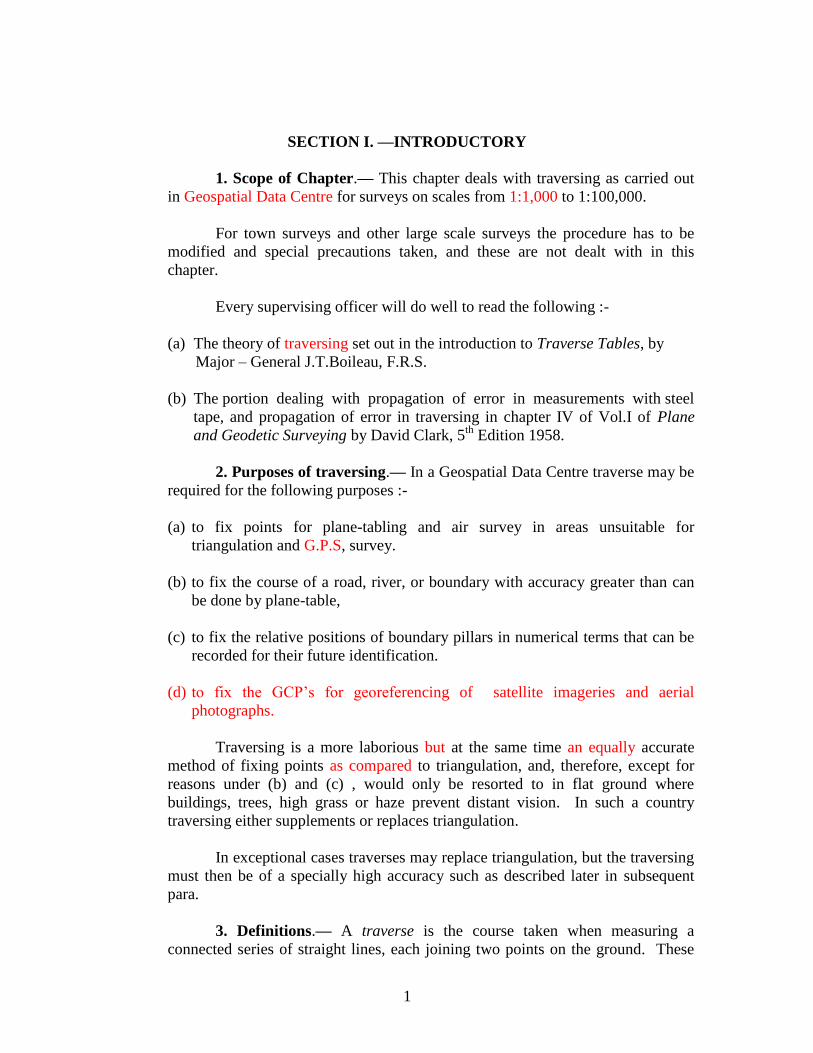
Thus a traverse starting at known station A and passing through B, C, D,
E, F, and returning to A, is a traverse circuit. A line traversed from B to E is
called a tie-line. Figures A B E F A and B C D E B are called sub-circuits.
The initial or starting station of a traverse is a point of known co-ordinates
from another traverse, triangulation resector, GPS surveys.
The origin of a traverse is the point from which rectangular co-ordinates
are computed, not necessarily a station of observation.
All traverses are computed from bearing/azimuth. A traverse bearing is
the angle which a traverse leg makes with the meridian at the origin of the survey
or at the station of observation as measured from north by east.
Convergency of meridians at latitude is the angle between their tangents
at latitude . It is computed from the formula:—
Convergency in seconds = Diff. of longitudes in seconds x sin .
It may be taken from Auxiliary Tables, Part III, II Sur.
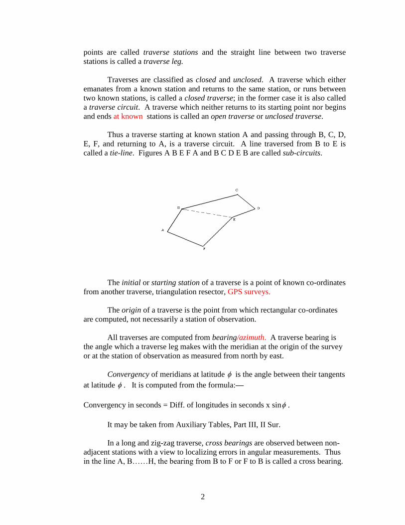
In a long and zig-zag traverse, cross bearings are observed between non-
adjacent stations with a view to localizing errors in angular measurements. Thus
in the line A, B……H, the bearing from B to F or F to B is called a cross bearing.
3
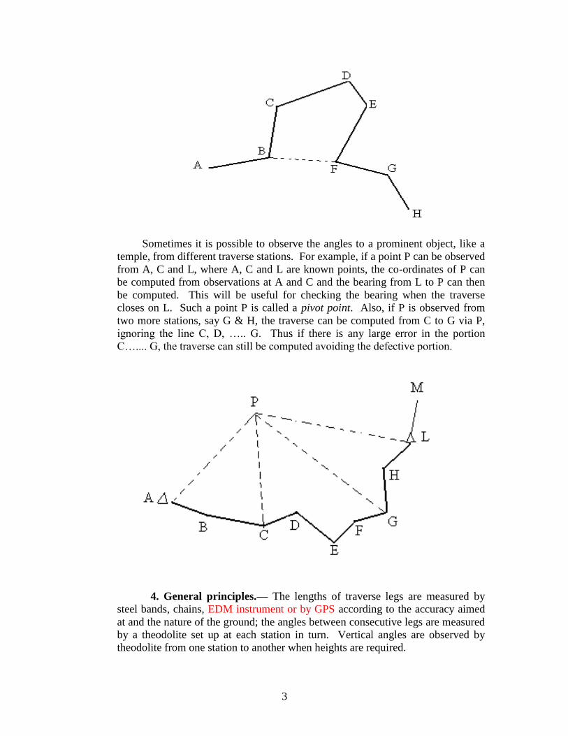
Sometimes it is possible to observe the angles to a prominent object, like a
temple, from different traverse stations. For example, if a point P can be observed
from A, C and L, where A, C and L are known points, the co-ordinates of P can
be computed from observations at A and C and the bearing from L to P can then
be computed. This will be useful for checking the bearing when the traverse
closes on L. Such a point P is called a pivot point. Also, if P is observed from
two more stations, say G & H, the traverse can be computed from C to G via P,
ignoring the line C, D, ….. G. Thus if there is any large error in the portion
C….... G, the traverse can still be computed avoiding the defective portion.
4. General principles.— The lengths of traverse legs are measured by
steel bands, chains, EDM instrument or by GPS according to the accuracy aimed
at and the nature of the ground; the angles between consecutive legs are measured
by a theodolite set up at each station in turn. Vertical angles are observed by
theodolite from one station to another when heights are required.
4
It is evident that if the position of one station and the bearing of a traverse line
connected to it are known, then the position of the next and all succeeding stations can be
computed.
5. Liability to errors.— A triangulator can determine the total error of his
angular measurements after completing observations at three stations of a triangle; he has
no linear measurements to make once the original base has been measured. His errors
can, therefore, be carefully watched as work proceeds.
A traverser on the other hand has to make repeated linear and angular
measurements, whose accuracy he can determine only when he has completed the
computations of a closed traverse. Even then, the fact that a traverse circuit closes
exactly on its own starting point, does not necessarily mean that the work is accurate, for
its length may be wrong altogether, or errors may have cancelled each other.
In an uneven country, the distances between traverse stations tend to be short,
and the large number of separate measurements, both linear and angular, mean a large
number of chances of error.
To control these errors, traverses must be run, either direct from one fixed point
to another, or, as is more usual when traversing an area of any extent, in a network or grid
connected with triangulated points where possible.
It is well to run main circuits along routes, such as roads or railways, where a
high standard of precision can be kept; if necessary, such main lines may be measured
with greater precision of observations than the sub-circuits or tie-lines.
6. Degree of accuracy required.— Whatever the scale of survey may be, the
accuracy of traverse work for topographical surveys should be such that there should be
no appreciable error of distance or azimuth between any two traverse stations plotted on
one sheet of the map.
The rate of accumulation of errors in traverse affects the accuracy of the map and
should kept under control by closing traverses on well fixed points at both ends.
Traverses of lengths of about 25 cm to 150 cm on maps should not close on fixed points
with an error of more than 1 in 1,000.
Longer lines of traverse which break up a large area into compartments, and
provide well fixed points on which to base shorter traverse lines, should be of higher
accuracy, say 1,25,000. Lines shorter than 25 cm on the map should be accurate between
1 in 1,000 to 1 in 2,000.
If two datum points are very close together, it may be that the direct traverse
measurement between them is more accurate than the computed distance between their
position as previously fixed. This may well be the case if the two points are fixed from
different series of triangulation. In such cases an apparently high percentage of error in
the traverse line is no cause for alarm, provided longer traverse lines close correctly on
these stations.
7.Scale of map affecting standard of accuracy.— The scale of the map affects
the standard of accuracy in two ways.
5
First— For small scale work, say on 1:50,000 scale, the standard of
accuracy may be very much lower than 1 in 1,000 for short distances, provided
that the average standard is maintained generally.
For example, if a chain was dropped in just one place, the 1:50,000 map
would hardly suffer at all, whereas the 1:500 scale map would be seriously
distorted.
Second— Points of higher standard of accuracy must be provided at very
much closer intervals on a large scale than on a small scale survey.
On the 1:50,000 scale it is sufficient to have datum points accurate to 10
metres, whereas on 1:500 scale an error of position of 2 metres is a serious matter.
8.Main traverses of special accuracy.— In some stretches of flat
country, main triangulation series lie over 150 km apart; and even where
secondary series have been run to connect them, many of the secondary points
have been destroyed. Owing to the flatness of the country the expense of
triangulating the intermediate area may be greater than justified by the class of
survey proposed, and triangulation might take several seasons to carry out.
If such an area containing very few triangulated points exceeds one degree
square, then ordinary traversing with the iron chain is most unsatisfactory. The
errors accumulated are large and difficult to distribute, and they can only be dealt
with properly when the whole gap has been filled up.
Such areas should be broken up by special main traverses run by crinoline
chain or the E.D.M instrument where available depending on the nature of the
ground.
Each main traverse should be run to form a circuit closing on triangulated
points or GPS points; and should be computed and adjusted independently of
subsidiary traverses as described in Para 68.
The following precautions should be taken to ensure as high a standard of
accuracy as possible—
( 1 ) Choose the best available routes for the traverse, having special
regard to straightness of line, smoothness of ground, and long rays
of observation.
( 2 ) Arrange lines to form quadrilaterals, in which the long side should
not be longer than twice the short side.
( 3 ) Use a good theodolite reading to 1second or less, and put a well
trained observer on the work.
6
( 4 ) At stations of observation, observe horizontal angles on two zeros,
and vertical angles on both faces.
( 5 ) Observe azimuths every 12th
station or thereabouts; these should be
accurate to 5 to 8 seconds, and should be observed to stars instead
of the sun. Polaris is the most convenient star (except in low
latitudes where East and West stars are to be observed‘.) for
traversers as it is visible just before dark. Computations are
worked out on departmental form.
( 6 ) In taking out computations, enter the seconds of all angles; and aim
at an accuracy of 1 in 5,000.
( 7 ) The traverser should have a specially selected staff of men, and
should have a recorder to assist him, and should on no account
leave the running of the chain to a tindal or a khalāsi.
9. Errors of angular measurement.—Along main circuits, lines of
observation should be as long as possible, and the sides of the enclosed figure
kept as straight as possible.
The total of the errors of angular measurement within a closed circuit can
be determined exactly*, but it is not possible to locate individual errors of
observation; these can however be controlled by the arrangement of sub-circuits,
cross bearings and the observation of a number of azimuths.
The observations of azimuths, either from sun or stars, at frequent
intervals, provides a direct check against accumulation of errors of angular
measurement. These azimuths, as well as the bearings from one station to
another, are usually computed in the field; if comparison reveals an error larger
than 2 minutes in 20 stations in subsidiary traverses and 1 minute in 12 stations in
case of main lines, the line will be re-observed.
Gross errors are readily detected if the theodolite is set up in the magnetic
meridian, or roughly to the north at each station, as described in para 36.
With stations ½ km apart, the ½ minute errors will give a displacement at
the end of one kilometer of 22cm, i.e., 1 in 4,500 with the traverse bearing 1
minute in error.
An error of 2cm in centering the theodolite or flag will cause an angular
error of 21 seconds on a line 200 metres long; but on a line of 40 metres the
angular error would be 1 minute and 43 seconds.
__________________________________________________________________
* If a closed figure has n sides, then the sum of all the interior angles is equal to
(2n X 90 – 360) degrees.
7
In both cases the displacement of the first forward point is insignificant, but the
error is carried forward to all subsequent bearing and displaces the whole traverse.
If a traverse were run with rays 40 metres in length for a distance of 1 kilometre,
with an error of 1 minute 43 seconds in the same direction in each angle, the
displacement at the end of one kilometer would be 6.5 metres ( an error of 1 in 150 ) with
the traverse displaced in bearing by 42 minutes and 58 seconds.
Traverse with Total station / EDM is dealt in Sec IV and Traverse with GPS is
dealt in Sec V.
10. Errors of linear measurement.— The most important field check in linear
measurements is the established custom of measuring each line twice and comparing the
values. Each line should be measured once with a 30 metre chain / steel band and a
second time with a 20 metre chain / steel band. When measured with chains the two
measures should agree within 1 in 500. For steel bands, the agreement should be better
than 1 in 1,000 Re-measurements should be done if the disagreement exceeds the above
limits.
There can be no further check till the meridians and perpendiculars are computed.
The subject of the determination and distribution of errors in traverse circuits is
dealt with in detail in section III, paras 67, 68 and 69.
11. Selection of origin.— Traverses are computed in rectangular co-ordinates
referred to an origin, either the initial station or some central point.
For many reasons it is best to adopt the centre of the degree sheet as the origin for
all traverse work in that sheet.
When a traverse line passes from one degree sheet to another the origin should be
changed. Points along the common margin of two degree sheets will be required in terms
of the two origins, and suitable tables can be prepared for conversion of these points from
one origin to another.
In the ordinary way, the labour of converting co-ordinates from spherical to
rectangular, or from one origin to another, is very heavy, and should be avoided as much
as possible. When connecting to triangulated points which are in spherical terms, or to
traverses which are referred to origins other than the centre of the degree sheet, a limited
number of points only should be converted, sufficient to make satisfactory connection.
If a large number of points from triangulation, or other traverse systems, fall into
an area of survey, a spherical mesh and one or more rectangular grids can be laid down
on the same sheet and the several series plotted independently.
8
In an isolated traverse, the initial station is sometimes taken as origin, and it is
then most important to determine the geographical position of this origin.
The error of projection by rectangular coordinates is less than 1 in 25,000 at
distance ½ a degree from origin, but is increased to about 1 in 800 at distance 3 degrees
from origin.
If co-ordinates are calculated at a very long distance from the origin, the high
number of units involved affects the accuracy of computations.
12. Qualifications of a traverser.— Traversing does not require such high
qualifications as triangulation, and an average traverser can soon master the work.
A traverser should be familiar with plane-tabling and should be capable of
Post-pointing on photographs, so that he may appreciate the suitability and number of
points a plane-tabler will require in the country he is working in. he must be well-drilled
in the management of his theodolite and chains, and must keep his field book neatly and
strictly according to rules.
The average traverser should not be allowed to make any adjustments to his
theodolite; these should always be attended to by an officer.
All traversers must conscientiously follow the procedure laid down in section II.
Careless and slovenly work is exposed in the subsequent computations, but errors cannot
be rectified once field work is closed. It is important, therefore, to keep a small
computing section in the field, and to have field books sent in month by month for check
and set up.
9
SECTION II.— FIELD WORK
13. Preliminary plans.— A traverse should originate from the best fixed point
available, and should be connected with other fixed points as frequently as possible.
Suitable points should be fixed in the traverse area by G.P.S in advance, if none exist
already; otherwise the traverser will be delayed by having to make his own connections.
When the traverse is to provide points from plane-tabling, it should be carried out
well in advance before the detail survey, to allow full time for computations, adjustment,
and plotting. On the other hand, traversing carried out several seasons in advance of
detail survey is of little value, as station marks and other points of a temporary nature will
not be found by the plane-tablers.
14. Out-turn.— The Officer in Charge of the survey will allot certain areas to
each traverser, and indicate generally the routes to be followed for the main circuits. He
will issue instructions as to the distance apart of traverse lines, and the number and nature
of the points to be fixed, having regard to the scale of subsequent survey and the
character of the country.
He must issue orders as to the observation of vertical angles. In flat country,
where no contouring is required, and where lines of leveling provide ― bench-mark‖
heights, no vertical angles at all need be observed by the traverser.
Where, however, lines of levelling do not exist, it is necessary to show the spot
heights above sea-level of some well distributed points in each sheet. For this purpose, in
flat areas controlled by traverse, sufficient height traverses should be run to enable this to
be done.
In country where there are gentle slopes, and contours are required at distant
intervals, or where, in lieu of levelling, a certain number of approximate heights are
required, vertical angles need only be observed along selected main lines of traverse.
In undulating country, which has to be carefully contoured, vertical angles will be
required along all lines of traverse, and work will be slower in consequence.
A traverser can run from two to ten kilometres of traverse a day, according to the
nature of the country, and the number of points fixed. In dense jungle, line clearing might
reduce the out turn to under one kilometre a day, though in some cases, such as the
traverse of a boundary, a jungle clearing squad in advance can save a certain amount of
time.
In open country with little detail and conspicuous points, where a plane table
traverse can be run several kilometres without error appreciable on the 1:50,000 scale,
lines of traverse may be from 5 to 10 kilometers apart for survey on that scale.
10
In broken country covered with dense forest, and with survey on the 1:10,000
scale, traverse lines would not be more than two to three kilometres apart.
The labour of computing and plotting a large number of traverse lines or
interersected points, is very heavy, and traversers should not spend time fixing more
stations and points than are necessary. Not only does this delay their own progress, but it
may also be impossible to get all this material ready before the plane-tablers have to start
field work.
15. Computing section.— Whilst traversers are at work, a small staff of
computers should be kept at field headquarters under the supervising officer.
Every month each traverser should send in all his azimuth observations, the field
books of all completed circuits, and a copy of his field chart.
This computing section requires—
Star Almanac for Land Surveyors for current year.
Auxiliary Tables, Parts II & III / Scientific calculator
Form 4 Trav.(Computation of Azimuth from Sun)
Form 7 Trav. (set up).
* Form 13 Trav. and 14 Trav. or 14 A Trav.(computation of co-ordinates).
Form 11 Topo (Azimuth from Sun or Star observations).
Form 8 B Lamb (Azimuth/Bearing from Polaris)
Form 17 Train (Computation of sides).
The computers will check all figures as they come in, compute all azimuths, and
set up the bearings of the circuits. They will bring to the notice of the officer all
irregularities, such as azimuths that fail to prove, neglect to compare chains,
discrepancies between chain measurements, discrepancies between deduced and observed
bearings. The computers will also see that good connections are made with triangulation
and old traverses, and also between neighbouring traverses.
The Officer-in Charge is then in a position to order traversers to re-observe or re-
measure such work as is necessary before the close of the field season.
In the office the strength of the computing section may need to be as much as
double the number of traversers at work in the field. The computations are bulky and
laborious, but the greater part of the work is quite simple, being either copying, or
looking out figures from tables. There must, however, be an officer or a very
experienced computer in charge, to supervise the setting up of the work, and breaking it
up into circuits and compartments that will best eliminate errors. The traverse
computations should be fully completed at least one month before field survey
commences, so as to leave time for careful and methodical plotting. This subject is more
fully dealt with in Section III.
--------------------------------------------------------------------------------------------------------- * Alternatively to 13 Trav. With logarithm tables, computations may be carried out on 14 A Trav. using 41 Sur. Part
III, Auxiliary Tables.
11
16. Squad.— A traverser usually requires a squad of men for carrying out the
following duties—
Carrying GPS, Stand, Antenna, other accessories - 03 men
Carrying Total Station or Theodolite, stand and umbrella - 02 men
Carrying Plane-table, stand and haversack - 01 man
Chainmen ( Long chain) - 02 men
Chainmen (short chain) - 02 men
Staff men - 02 men
Camp orderly - 01 man
Dak man (if required) - 01 man
Two men out of these should preferably be mates or tindals. In addition to the
above, men required for jungle-clearing may be employed locally.
17. Instruments.— A traverser requires the following instruments in normal
country—
1 Theodolite, magnetic compass, and stand with centring motion.
1 Plane-table complete, with cover, sight rule, and rectangular compass.
1 Umbrella (Large size).
1 Pair of binoculars.
2 GPS instruments with antenna and accessories for a team of two.
1 Total Station and other accessories
3 Target fitted with optical prism
2 Heliotropes (for connection with triangulation).
2 30 metre chains, with pins.
2 20 metre chains, with pins.
1 30 metre steel tape.
— Crinoline chains ( if required for precision traverses )
1 Pair pliers for repairing chains.
1 Maul or mallet for driving pickets.
1 Hammer and chisel for mark-stones.
— Jungle-cutting implements according to country.
3 Traverse staves ( for vertical angles only)
4 Traverse flags.
3 Small mirrors, for signaling between stations in jungle.
— Field book forms, 2 Trav. and cover forms, 2 (a) Trav.
— Angle book forms, 3 Topo. for azimuth observations.
— Computation forms, Auxiliary Tables Parts II & III and
Field Traverse Tables, scientific calculator
12
18. Theodolites.— Before issuing a theodolite to a traverser, the Camp Officer
should examine it carefully, and see that it is in smooth working condition, that its stand
is rigid, and that the foot-screws do not shake in their bearings. The body level should be
adjusted to the centre of its run; the horizontal and vertical wires should be true, and the
collimation errors should be small.
The traverser should never take his theodolite to pieces himself, but should send it
to his Camp Officer for any adjustments that may be necessary. He should entrust the
carriage of the instruments, when at work, to the steadiest of his khalāsis, and must use
his discretion as to whether it should be carried on its tripod or in its box, according to the
nature of the ground; the traverser, and not the khalāsi, is responsible for its safety.
The theodolite to be used depends on the accuracy aimed at. For main traverses of
1:5,000 accuracy, a good theodolite ( preferably Glass arc) reading to 1 second or less is
necessary. For subsidiary traverses though a vernier theodolite is adequate, a glass arc
theodolite is preferred. A theodolite which transits without change of pivots is more
convenient for azimuth observations. The stand with centring motion is a great
advantage, for it allows the whole instrument to be shifted bodily over the mark, after the
tripod has been set.
Good work can only be obtained from good instruments well maintained. The
completion of the History Card is essential to this maintenance and to locating possible
instrumental errors when results are discordant.
At the close of the field season, each theodolite should be examined by an officer,
who will submit a report on its condition on form O.65 (Adm.) to the Officer-in-Charge.
For instructions as to cleaning and general care of theodolites, and all
adjustments, see Topo Handbook Chapter III (Triangulation and its Computation ).
19. Chains. — Distances should be measured with a long chain (30 - metre ) and
a short chain ( 20 - metre) for subsidiary traverse. The main points in the specification
for metric surveying chains are given below :-
( i ) Although the chains are supposed to stand an amount of rough usage, it is
important that they are handled carefully. The chains are liable to appreciable alterations
in length, and, therefore, require to be compared at frequent intervals with a standard
such as a steel tape or steel band.
( ii ) If the overall length is found to be incorrect, then every metre length should
be checked against the standard and length corrected by means of adjustable connecting
links.
( iii ) The overall distance between the outside surfaces of the handles when fully
stretched is the correct length of the chain.
13
( iv ) To facilitate holding the arrows or chain-pins, a groove shall be cut on the
outside surface of each handle.
( v ) To enable the reading of fraction of a chain without difficulty, tallies shall be
fixed at every one and two or five-metre length and brass rings shall be provided at every
metre length except where tallies are attached.
The hard work to which they are put, soon causes chains to stretch or even break,
so that when issuing old chains, the Camp officer should not only adjust their lengths
accurately, but should see that the rings and tallies are at correct intervals of one metre
and two or five metres.
Both the chains should be checked daily against the standard before commencing
work and errors recorded in the field book cover, form 2 (a) Trav.
A steel tape is the best standard for checking the chains, but tapes are expensive
and liable to break and rust, so it may be necessary to use a standard chain instead. As a
standard chain would itself be liable to stretch, the traverser should be provided with two
standards, one of which should be sent to the Camp Officer for adjustment at stated
intervals.
20. Steel bands. — Steel band has become quite common for measuring lengths
and should be used in preference to the ordinary chain especially when accuracy higher
than 1 in 1,000 is required. Steel bands are of width 15 mm, thickness 0.5 mm, lengths
20 or 30 m. Large brass stud markings are made at every metre, subdivided by small
brass studs at every tenth of a metre. These have swivel handles at both ends and are
wound on drums of 25 and 40 cm diameter respectively.
Lengths of steel bands should be checked against a standard steel tape or against
standard length before issue to the traverser.
For main traverses only crinoline chain should be used.
21. The Crinoline chain. — The crinoline chain is a ribbon of steel about 3 to 5
mm wide and about ½ mm thick. It is obtainable in lengths of 100 to 110 metres and is
normally wound on drums of 30 cm diameter. For convenience in handling, it may be
divided into sections of 20 or 22 metres with brass tacks at every metre and every 20 cm,
the last 20 cm portion subdivided into 10 equal parts. Brass handles and grips for
applying tension are supplied with the chains. Depending on the length of the chain, a
tension of 15 kg may be applied during measurement. It is important to remember that the
tension applied during field measurements should normally be the same as that applied
during calibration in the Geodetic and Research Branch.
Having no links which could deform, and very few wearing surfaces, the crinoline
chain is not susceptible to serious changes or uncertainties in length, the only sources of
error being those due to the nature of the ground, changes in temperature and any
difference in tension. Due to its greater length much fewer chain measures are required
with it than with an ordinary 20 metre chain. The error due to the marking pins at the end
14
of every chain with a 100 metre chain is less than half of that with a 20 metre chain. On
account of its lightness it can be drawn tight over moderate size gaps such as a canal or
small nāla. Because of its greater length, it is desirable that it should not be dragged
from the front end, but that two or three men should carry it at intermediate points along
its length. The chain should not be jerked violently for straightening. The intermediate
men should lift it clear of obstacles and place it gently along the straight line.
The crinoline chain is delicate and liable to break if fouled, stepped over, pulled
roughly, or jerked violently. It is, however, capable of repair in the field with the help of
brass sleeves obtainable from the suppliers. It is important that the fact of breakage
should be recorded in the field book and a comparison made with another standardized
chain as soon as possible. In a chain made in sections, the junction links should be
measured and recorded at the start of work and frequently thereafter.
The additional care required in manipulating this chain, and extra expense in
consequence thereof, will be more than compensated by the smaller amount of labour
necessary for the closing of the various circuits. In addition, much higher accuracy is
likely to be achieved.
Although the suppliers guarantee the accuracy of the intermediate one-metre tacks
to ¼ to ½ mm, yet it is generally more convenient to measure end lengths smaller than 20
metres with a steel tape. Ordinary chain pins can be used to mark a chain length but if
better accuracy is desired, a peg may be driven in the ground and the chain end marked
with a cross on the peg with a pencil by drawing a line along the chain and another at
right angles at the end mark. It is desirable that the traverser should himself accompany
the forward end of the chain and draw these lines himself, or if chain pins are used, see
that the pins are properly put into the ground.
The measurement of the odd length at the end must be done by the traverser
himself.
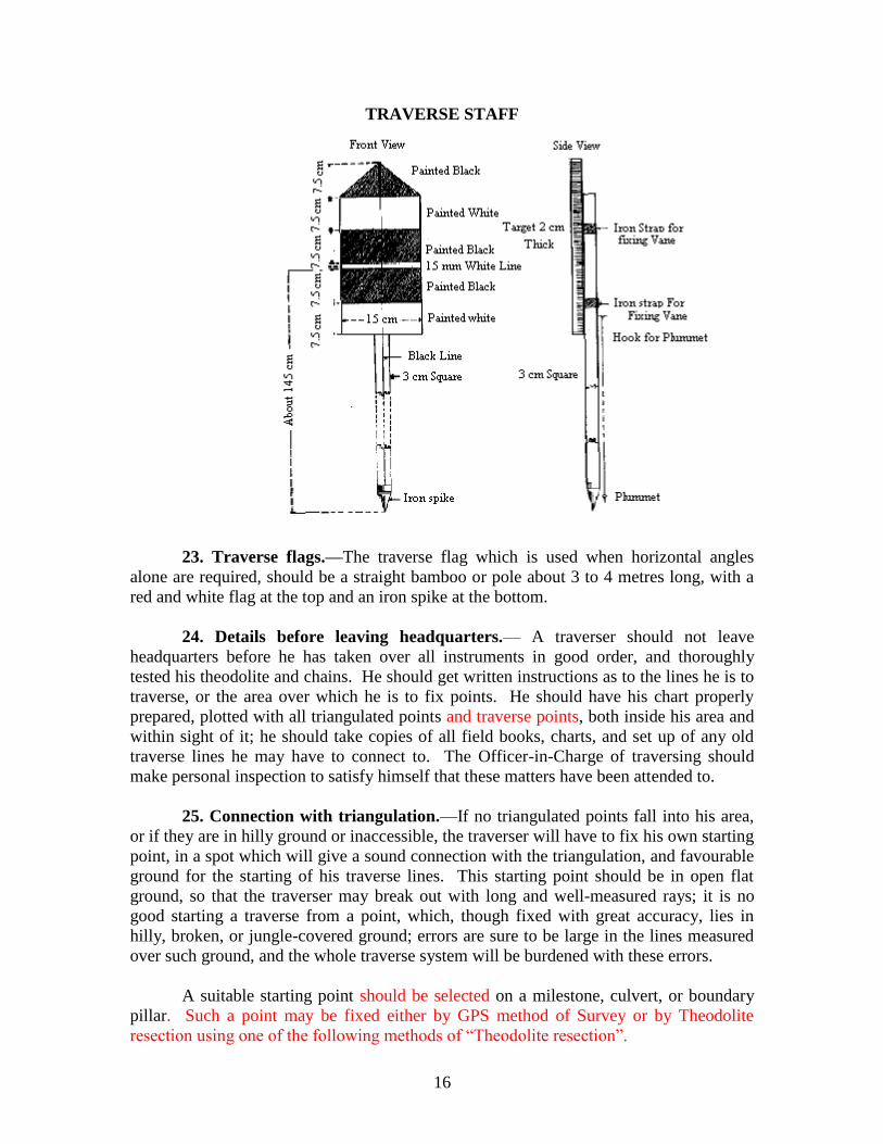
22. Traverse staff for vertical angles.— The traverse staff, of which a sketch is
given on the next page, is required for observing vertical angles, but it may also at times
be conveniently used for measuring the horizontal angles of a traverse when the station
marks themselves cannot be observed. It is essential that the staff should be truly
vertical, and to ensure this the plummet at the back of the staff should always be used.
It gives a mark of observation that can be adjusted to the same height above the
forward or back mark as the telescope is above the station mark. It is used in the
following way—
Each traverser should be supplied with three staves— one forward, one back, and
one for the end of his base line when measurements by means of triangulation are
necessary. At the commencement of the season, the traverser sets up his theodolite on
level ground at a convenient working height, then measures the height of the telescope
from the ground, and adjusts the centre line on the target to measure this height from the
foot of the staff, either by altering the screws or by cutting a bit off the bottom. All his
targets must of course be similarly adjusted and he should then mark his name on them.
15
He will then measure, by means of a spare plummet line, the height from the ground to
the plummet hook of the theodolite, and make a large knot in the string to indicate this
height, which may be called the ―normal height‖.
Now suppose the instrument, set up and level over the first station of a traverse,
and the forward staff in position over station 2; then, before making an intersection,
measure with the spare plummet string the height from the station mark to the plummet
hook of the instrument. The height so found must be either (1) x centimeters greater, (2)
y centimeters less, or (3) exactly equal to the ―normal height‖.
In the first case the target must be intersected x centimeters above the centre line,
in the second case y centimeters below that line, and in the third case on that line.
The distance x or y on the string, above or below the knot can be readily estimated
by eye, or if preferred can be measured along a scale of centimeters cut on the legs of the
theodolite: it is generally small and will rarely exceed 15 centimetres. The target being
printed in 75 mm horizontal stripes of black and white, the intersection can always be
made within 2 centimetres or less of the correct position by intersecting at a distance
above or below the centre line of the target equal to the distance indicated by the string;
and this is sufficiently close for all practical purposes. Even in rough ground the vertical
error will not exceed 20 to 40 centimetres in a kilometer provided the collimation error
of the instrument is properly dealt with.
16
TRAVERSE STAFF
23. Traverse flags.—The traverse flag which is used when horizontal angles
alone are required, should be a straight bamboo or pole about 3 to 4 metres long, with a
red and white flag at the top and an iron spike at the bottom.
24. Details before leaving headquarters.— A traverser should not leave
headquarters before he has taken over all instruments in good order, and thoroughly
tested his theodolite and chains. He should get written instructions as to the lines he is to
traverse, or the area over which he is to fix points. He should have his chart properly
prepared, plotted with all triangulated points and traverse points, both inside his area and
within sight of it; he should take copies of all field books, charts, and set up of any old
traverse lines he may have to connect to. The Officer-in-Charge of traversing should
make personal inspection to satisfy himself that these matters have been attended to.
25. Connection with triangulation.—If no triangulated points fall into his area,
or if they are in hilly ground or inaccessible, the traverser will have to fix his own starting
point, in a spot which will give a sound connection with the triangulation, and favourable
ground for the starting of his traverse lines. This starting point should be in open flat
ground, so that the traverser may break out with long and well-measured rays; it is no
good starting a traverse from a point, which, though fixed with great accuracy, lies in
hilly, broken, or jungle-covered ground; errors are sure to be large in the lines measured
over such ground, and the whole traverse system will be burdened with these errors.
A suitable starting point should be selected on a milestone, culvert, or boundary
pillar. Such a point may be fixed either by GPS method of Survey or by Theodolite
resection using one of the following methods of ―Theodolite resection‖.
17
26. Theodolite resection.— (a) Resection from three or more triangulated points.
If the traverser finds a suitable starting point from which three or more well-defined
triangulated stations or points are recognized, he can fix his position by observing two or
more complete rounds of angles to these points. In at least two of these rounds he should
include the forward station of his traverse line, and he should invariably observe an
astronomical azimuth.
As a general rule the traverser should observe to every well defined triangulated
point which he can recognize; three points will give a solution, provided they are
properly identified, and the values taken for their positions are absolutely true; but
observations made to unvisited points are often unreliable, and it is well to have points in
reserve. Vertical angles should always be observed in making these resections, as they
afford a good check on the identity of the stations. If possible there should be a
heliotrope and flag at each station observed to. Computations are worked out on 27
Topo. with spherical, and on 28 Topo. with rectangular, data.
The best resection is obtained if two near points are observed which will give a
right angle intersection, besides one distant point for accuracy of bearing. A safe rule is
to choose points so that the resection is inside the triangle formed by them and that they
are as nearly as possible angularly equidistant.
If the resected point falls on or near the circumference of the circle passing
through the observed points no solution at all can be obtained without an observed
azimuth. In such circumstances the traverser should also visit one of the triangulated
points and observe a complete round of angles from it.
Appendix II gives an easy solution of the problem by which errors can be
eliminated, and the accuracy of the rays to all the points observed rapidly demonstrated
by graphical methods.
(b) When only two triangulated points are visible.
First— In this case the starting point of the traverse forms a single triangle when
connected with the two visible points; if all three angles of this triangle are observed the
triangle can then be solved.
Second— A solution may be obtained if the traverser observes the angle at his
starting point between the two fixed points and also observes the azimuths to both of
them; but there is no check on the identity of the stations observed or the accuracy of the
positions taken for them. Computations may be worked out on 24 Topo.
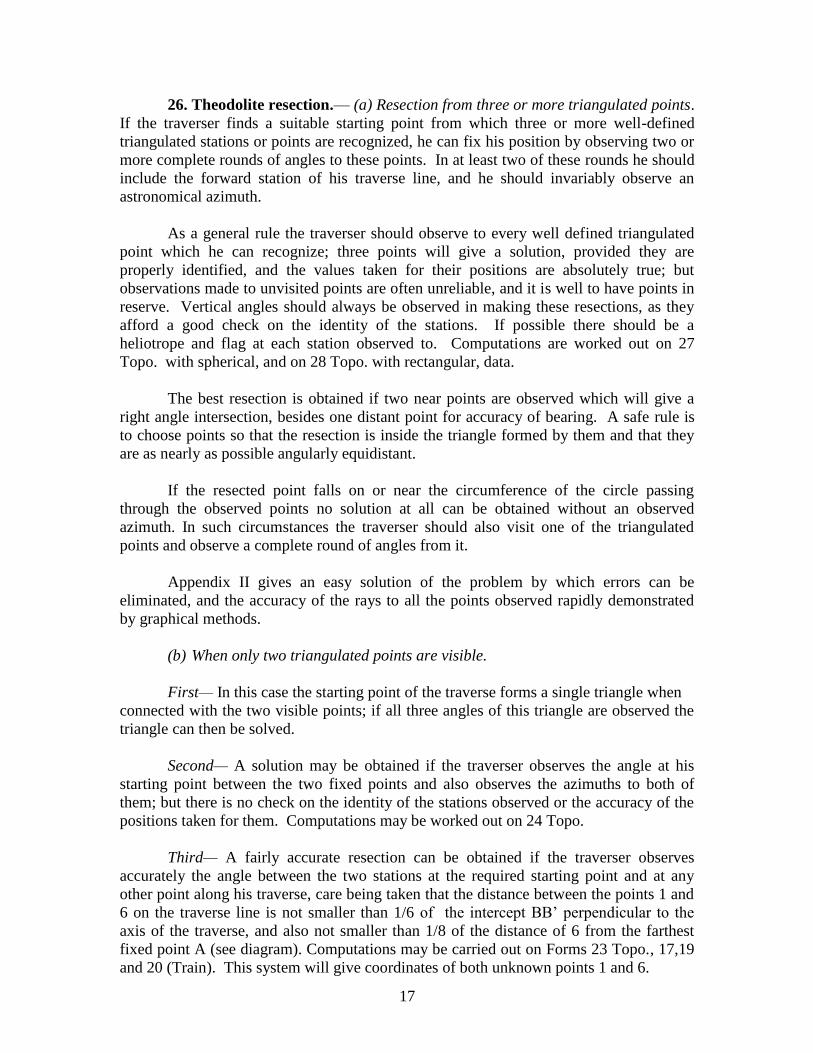
Third— A fairly accurate resection can be obtained if the traverser observes
accurately the angle between the two stations at the required starting point and at any
other point along his traverse, care being taken that the distance between the points 1 and
6 on the traverse line is not smaller than 1/6 of the intercept BB‘ perpendicular to the
axis of the traverse, and also not smaller than 1/8 of the distance of 6 from the farthest
fixed point A (see diagram). Computations may be carried out on Forms 23 Topo., 17,19
and 20 (Train). This system will give coordinates of both unknown points 1 and 6.
18
(c) When only one triangulated point is visible.
The traverse may be closed or started by measuring a base line of suitable length,
and connecting each end of it with the triangulated point provided that —
(1) no angles of the triangle so formed shall be less than 10º,
(2) all three angles of the triangle be observed,
(3) when observing at the triangulated point, another triangulated station or point
be included in the round of angles to each end of the base, so that the bearing
may be obtained from the triangulation. Failing this an astronomical azimuth
must be observed.
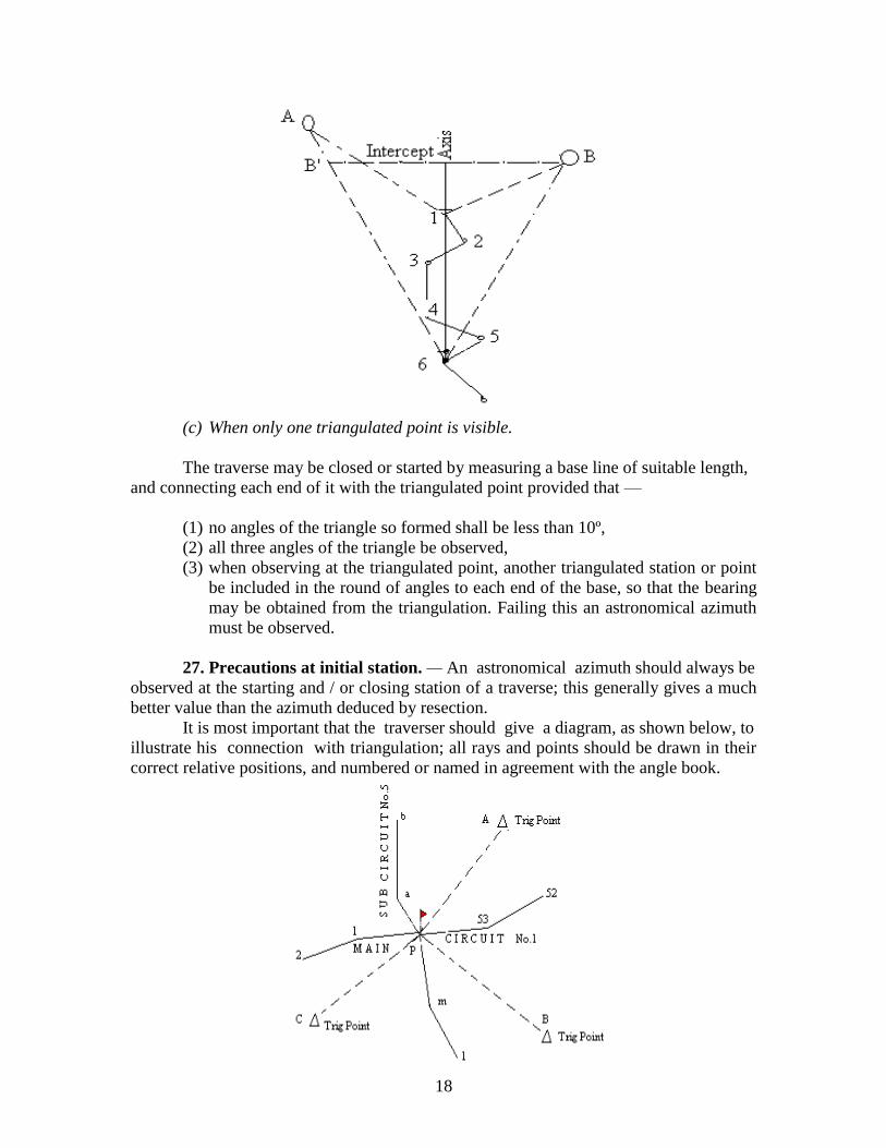
27. Precautions at initial station. — An astronomical azimuth should always be
observed at the starting and / or closing station of a traverse; this generally gives a much
better value than the azimuth deduced by resection.
It is most important that the traverser should give a diagram, as shown below, to
illustrate his connection with triangulation; all rays and points should be drawn in their
correct relative positions, and numbered or named in agreement with the angle book.
19
All observations at a starting or closing station must be taken on both faces, and
on one or more zeroes according to the nature of the theodolite used.
28. Connection with old traverse.— When a traverser has to connect to an old
traverse line he should take every care to ensure correct identification of the old traverse
marks. He should consult the field books, charts, and set up of the old work on the
ground; he should measure the horizontal distances and the angular bearings from his
connecting station to the old stations on either side; if these do not agree with the values
given in the old records, another connecting station must be chosen.
If the traverser makes a complete set of observations at three consecutive stations
of an old traverse it should be possible to identify these stations later on by comparing
angles and distances with the old records, and the connection would then be perfectly
good. The traverser can, however, seldom be confident that he has found three
consecutive stations of a traverse over a year old, unless he has the old records with him
for verification.
Often an intersected or offset point of an old traverse can be more readily
identified than the stations of observation.
29. Field traverse chart.— Every traverser should keep up a chart properly
mounted on a plane-table, vide specimen field chart (Plate IV). The scale of the chart
should, as a rule, be the scale of the subsequent survey. Before taking the field the chart
should be plotted with all triangulation data, and all existing traverse stations and points
which could possibly be of use. All existing levelling lines and bench-marks near the
traverse should also be plotted Bench-marks to which the traverser makes connection
should be marked by a conspicuous green cross.
The supervising officer should mark on the chart, or on a map of the country, the
approximate courses of the lines to be traversed.
The traverser, who should always have had some training as a plane-tabler, will
keep up in the chart a plane-table survey of the route he follows. He will mark clearly
every traverse station and intersected point, and the more important of the points fixed by
offset. He will number these to agree with his field book.
Each circuit and each tie-line should be given a distinctive name and number, and
each station should have a distinctive number or letter. Stations of adjacent circuits
should be so numbered that there will be no chance of confusion. It is preferable to
prefix the initial of the observer thus (R-14)/10, where R stands for Ram Singh,
Traverser, 14 the circuit number and 10 the station number.
The traverser will show on his chart all information likely to be useful to the
plane-tabler, such as important roads, rest-houses, markets and principal towns. The
chart need not be rigorous survey, but should be very clear and legible; it is convenient to
use an exiting map of the country, or the enlargement of one as a chart, in which case the
traverser might accept the detail on the map in preference to his own plane-table survey.
20
In an unsurveyed country any detail which the traverser can show on his chart
would be of great value later, but as a rule the survey of such detail must not be allowed
to delay the traverse.
30. Traversing and plane-tabling concurrently.— In certain cases a theodolite
traverse can be combined with a plane-table survey, the surveyor keeping up the plane-
table survey at the same time as he runs his traverse. Such work is not suitable for the
survey of areas, but is well suited to survey a coast line, river, road, or boundary, where
all detail to be surveyed can be fixed from the traverse stations, or from points along the
chained line.
The plane-table survey is in this case a high grade traverse chart; the smaller
detail is fixed by plane-table and sight rule, theodolite observations being confined to the
actual traverse line and a few distant points. When the field work is completed, the
traverses are computed and adjusted, and the results plotted. The detail from the plane-
table is then adjusted to the plot of the traverse stations.
This method is most economical in time and labour.
31. Astronomical azimuths.— Astronomical azimuths must be observed at
starting and closing stations and after every 15 or 20 stations, to obtain a bearing for
computation and prevent an accumulation of horizontal angular errors. If the traverser
can introduce an azimuth into his traverse line by observing at a triangulated station to a
second reliable station or point, then only may he dispense with an observed astronomical
azimuth.
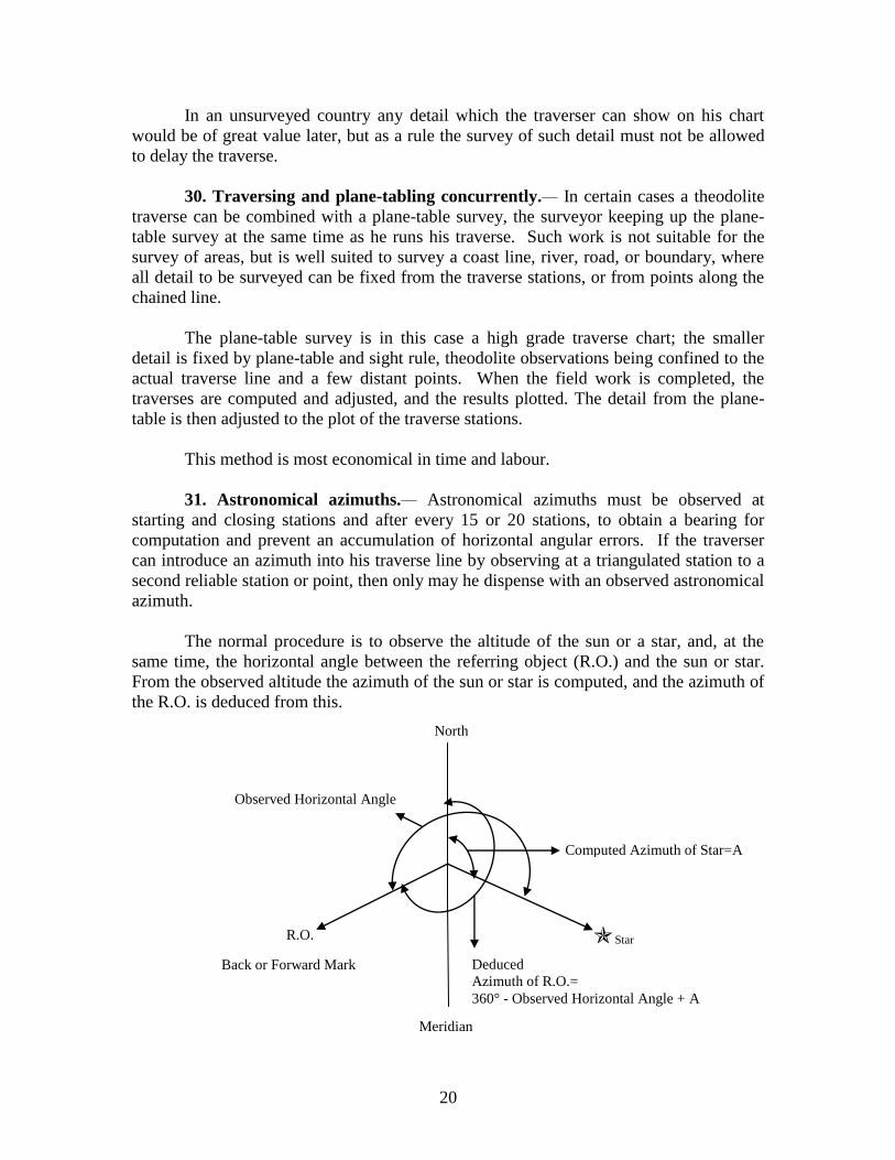
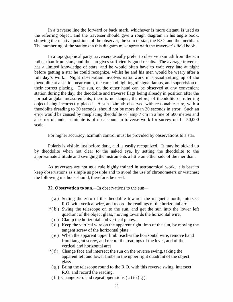
The normal procedure is to observe the altitude of the sun or a star, and, at the
same time, the horizontal angle between the referring object (R.O.) and the sun or star.
From the observed altitude the azimuth of the sun or star is computed, and the azimuth of
the R.O. is deduced from this.
Observed Horizontal Angle
Computed Azimuth of Star=A
R.O. Star
Back or Forward Mark Deduced
Azimuth of R.O.=
360° - Observed Horizontal Angle + A
Meridian
North
21
In a traverse line the forward or back mark, whichever is more distant, is used as
the referring object, and the traverser should give a rough diagram in his angle book,
showing the relative positions of the observer, the sum or star, the R.O. and the meridian.
The numbering of the stations in this diagram must agree with the traverser‘s field book.
In a topographical party traversers usually prefer to observe azimuth from the sun
rather than from stars, and the sun gives sufficiently good results. The average traverser
has a limited knowledge of stars, and he would often have to wait very late at night
before getting a star he could recognize, whilst he and his men would be weary after a
full day‘s work. Night observation involves extra work in special setting up of the
theodolite at a station near camp, the care and lighting of signal lamps, and supervision of
their correct placing. The sun, on the other hand can be observed at any convenient
station during the day, the theodolite and traverse flags being already in position after the
normal angular measurements; there is no danger, therefore, of theodolite or referring
object being incorrectly placed. A sun azimuth observed with reasonable care, with a
theodolite dreading to 30 seconds, should not be more than 30 seconds in error. Such an
error would be caused by misplacing theodolite or lamp 7 cm in a line of 500 metres and
an error of under a minute is of no account in traverse work for survey on 1 : 50,000
scale.
For higher accuracy, azimuth control must be provided by observations to a star.
Polaris is visible just before dark, and is easily recognized. It may be picked up
by theodolite when not clear to the naked eye, by setting the theodolite to the
approximate altitude and swinging the instruments a little on either side of the meridian.
As traversers are not as a rule highly trained in astronomical work, it is best to
keep observations as simple as possible and to avoid the use of chronometers or watches;
the following methods should, therefore, be used.
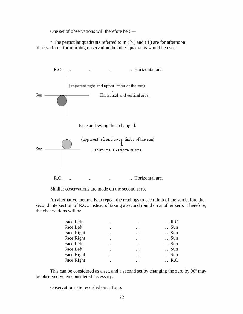
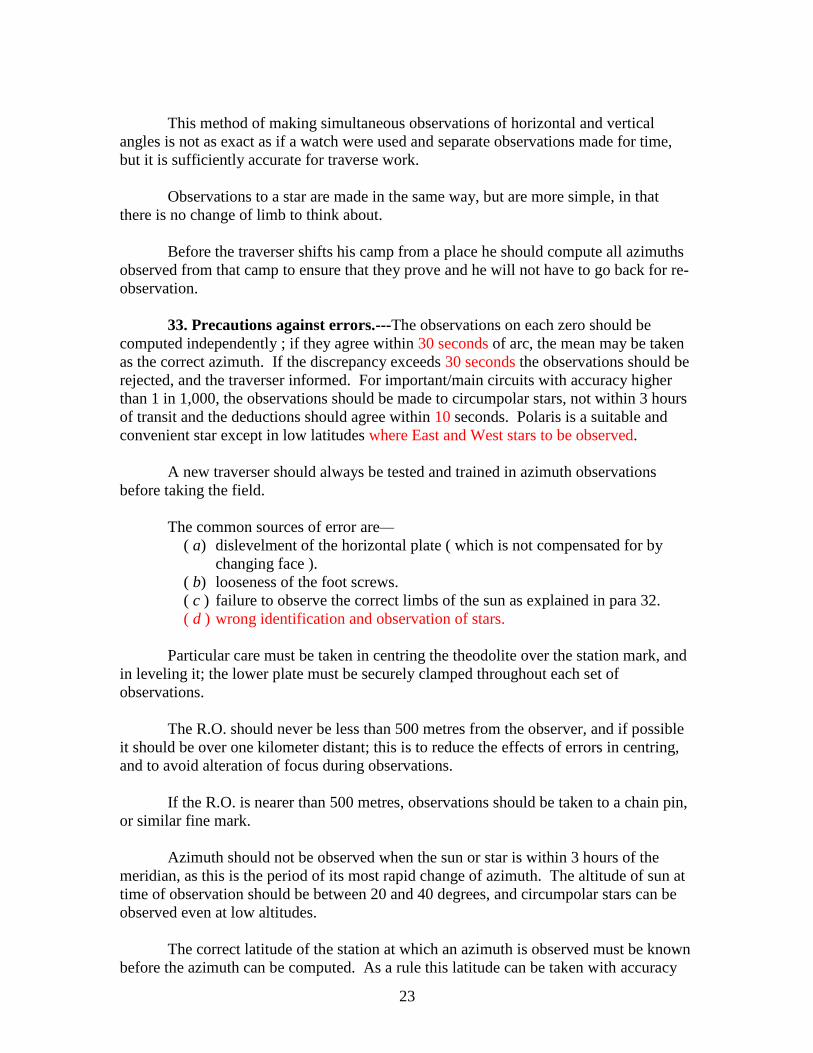
32. Observation to sun.—In observations to the sun—
( a ) Setting the zero of the theodolite towards the magnetic north, intersect
R.O. with vertical wire, and record the readings of the horizontal arc.
*( b ) Swing the telescope on to the sun, and get the sun into the lower left
quadrant of the object glass, moving towards the horizontal wire.
( c ) Clamp the horizontal and vertical plates.
( d ) Keep the vertical wire on the apparent right limb of the sun, by moving the
tangent screw of the horizontal plate.
( e ) When the apparent upper limb reaches the horizontal wire, remove hand
from tangent screw, and record the readings of the level, and of the
vertical and horizontal arcs.
*( f ) Change face and intersect the sun on the reverse swing, taking the
apparent left and lower limbs in the upper right quadrant of the object
glass.
( g ) Bring the telescope round to the R.O. with this reverse swing, intersect
R.O. and record the reading.
( h ) Change zero and repeat operations ( a) to ( g ).
22
One set of observations will therefore be : —
* The particular quadrants referred to in ( b ) and ( f ) are for afternoon
observation ; for morning observation the other quadrants would be used.
R.O. .. .. .. .. Horizontal arc.
Face and swing then changed.
R.O. .. .. .. .. Horizontal arc.
Similar observations are made on the second zero.
An alternative method is to repeat the readings to each limb of the sun before the
second intersection of R.O., instead of taking a second round on another zero. Therefore,
the observations will be
Face Left . . . . . . R.O.
Face Left . . . . . . Sun
Face Right . . . . . . Sun
Face Right . . . . . . Sun
Face Left . . . . . . Sun
Face Left . . . . . . Sun
Face Right . . . . . . Sun
Face Right . . . . . . R.O.
This can be considered as a set, and a second set by changing the zero by 90º may
be observed when considered necessary.
Observations are recorded on 3 Topo.
23
This method of making simultaneous observations of horizontal and vertical
angles is not as exact as if a watch were used and separate observations made for time,
but it is sufficiently accurate for traverse work.
Observations to a star are made in the same way, but are more simple, in that
there is no change of limb to think about.
Before the traverser shifts his camp from a place he should compute all azimuths
observed from that camp to ensure that they prove and he will not have to go back for re-
observation.
33. Precautions against errors.---The observations on each zero should be
computed independently ; if they agree within 30 seconds of arc, the mean may be taken
as the correct azimuth. If the discrepancy exceeds 30 seconds the observations should be
rejected, and the traverser informed. For important/main circuits with accuracy higher
than 1 in 1,000, the observations should be made to circumpolar stars, not within 3 hours
of transit and the deductions should agree within 10 seconds. Polaris is a suitable and
convenient star except in low latitudes where East and West stars to be observed.
A new traverser should always be tested and trained in azimuth observations
before taking the field.
The common sources of error are—
( a) dislevelment of the horizontal plate ( which is not compensated for by
changing face ).
( b) looseness of the foot screws.
( c ) failure to observe the correct limbs of the sun as explained in para 32.
( d ) wrong identification and observation of stars.
Particular care must be taken in centring the theodolite over the station mark, and
in leveling it; the lower plate must be securely clamped throughout each set of
observations.
The R.O. should never be less than 500 metres from the observer, and if possible
it should be over one kilometer distant; this is to reduce the effects of errors in centring,
and to avoid alteration of focus during observations.
If the R.O. is nearer than 500 metres, observations should be taken to a chain pin,
or similar fine mark.
Azimuth should not be observed when the sun or star is within 3 hours of the
meridian, as this is the period of its most rapid change of azimuth. The altitude of sun at
time of observation should be between 20 and 40 degrees, and circumpolar stars can be
observed even at low altitudes.
The correct latitude of the station at which an azimuth is observed must be known
before the azimuth can be computed. As a rule this latitude can be taken with accuracy
24
from the traverser‘s field chart; but if the traverser is unable to give the exact latitude of
his station, he should observe azimuths either to a pair of east and east stars, or to the sun
both before and after noon on the same day.
The traverser must enter in his angle book the date of each observation, as well as
the time of day and the magnetic bearing of his R.O.
The temperature of the air also should be estimated to the nearest 5 degrees of
centigrade and recorded. The atmospheric pressure should also be recorded ― for
computation of atmospheric refraction‖.
34. Detailed Procedure at a Traverse Station :-
35. The Wild Universal theodolite:— When using a Wild theodolite, a
different procedure is necessary, since the instrument has no slow motion screw on the
lower plate and no attached compass. The following rules should be followed, if ordinary
traverse accuracy is required:
a) Set up the theodolite face left on the stand; centre is over the mark and level it.
The vertical circle of a Wild theodolite is on the side opposite the micro
meter. Consequently a Wild theodolite is F.L. when the micrometer eyepiece
is on the right of the telescope.
b) Point the telescope towards the north, which can be estimated with sufficient
accuracy from the plane-table or map; and set the horizontal circle to read
zero.
c) Intersect the back station, and record horizontal and vertical readings.
d) Intersect the forward station, and record horizontal and vertical readings.
e) Make an arbitrary change of zero by giving the milled zero setting screw a
few turns. The change should be atleast 20º.
f) See if the forward station is still intersected, and re-intersect if necessary.
Record the horizontal reading only.
g) Intersect the back station and record the horizontal reading only.
If the reason for using a Wild theodolite is that special accuracy is required, a suitable
programme must be ordered.
Readings of the vertical circle are recorded in the first column of 2 Trav. in the usual
way.
The traverser should pay particular attention to the mode of graduation of the vertical
circle of his theodolite. In some old models of the Wild Universal theodolites, the mode
of graduations of the vertical circle would be such that the difference between the
25
reciprocal vertical circle readings, at opposite ends of a ray would give the
elevation/depression of the ray; while in the modern instruments half the difference
between the reciprocal readings would give the required elevation/depression.
The horizontal readings are recorded in the third column as usual, except that there are
4 readings. The two values of the deduced angle are the 2nd
reading minus the 1st and the
3rd
minus the 4th
(from the bottom of the form).
The two measures of the same angle should agree within 10 seconds when the
accuracy of the traverse is expected to be 1 in 5,000.
36. Errors of angular measurements:— The mutual agreement of the angles
observed is no guarantee that the true angle has been obtained. If a careless traverser
makes a gross error in reading his degree scale, he may confirm this error in his repeat
observations, or overlook it in taking out his deduced angles. Bad work of this nature is
shown up if the theodolite is set to the magnetic meridian at each station.
Small errors may be caused by incorrect centering of the theodolite over the
station mark, or by observing to a point not vertically over the marks of the back or
forward stations.
The centering of the theodolite is facilitated by the use of a stand with centering
motion, which allows a small lateral shift of the instrument in any direction, after the
stand has been firmly planted.
Khalāsis must be trained to hold the traverse staff or flag vertically over the
marks at forward or backward stations. There must be no shifting of a mark once any
observation has been taken to it.
Observations should always be taken to the lowest visible point of the staff. At a
distance of 20 metres an error of 25 mm in the centering of the theodolite, or the
intersection of mark, will produce an angular error of nearly four minutes.
The observer can always tell if a flag is out of the vertical by bringing it on to the
vertical wire of his telescope and swinging the telescope vertically.
When the traverse leg is less than 200 metres,a chain pin or similar thin object
should be used instead of the traverse staff for accurate intersection with the vertical wire.
The final intersection should always be done using the slow motion screw. The
last turn of the screw should be in the direction pressing against the spring.
The back station must always be intersected first, so that the traverse angle (or the
clockwise angle) will be measured. If the forward station instead of the back station is
intersected first, the angle that will be measured will be the reflex angle (i.e., 360º –
traverse angle) and this, if not duly noted down by the traverse in his field book and
consequently not known to the computer, will introduce errors in the bearings in the
traverse set up.
26
Intersected points should be mixed with the observations described in para 35 (c )
to (g). They should be taken on a separate round, with the instrument set in the magnetic
meridian, and the back station included in the round. This round is best observed whilst
the khalāsis is walking on to the forward station.
The traverser must keep his rays of observation as long as possible. Error
accumulate very rapidly in a sequence of short rays, and though the position of the
stations at which the errors were made will hardly be affected, owing to the shortness of
the distance, yet the accumulated error of bearing is carried forwarded to the rest of the
traverse, and may seriously affect the position of later stations.
The shorter the distances between traverse stations, the more frequently will
azimuth observations be required.
When a traverse is being run on one face only, there is risk of error if the
theodolite should go out of adjustment in collimation of the vertical wire, or by
dislevelment of the transit axis. If the collimation error amounts to θ minutes, and if the
two rays observed at a station have elevations of α ° and β° the error in the horizontal
angle measured will be θ (sec α – sec β) minutes. Similarly, if the transit axis is out of
level by Φ minutes, the west end being too high, the error will be Φ (tan α – tan β). It is
clear that these errors are only likely to be serious if the elevations are steep, and that the
transit axis error is likely to be the most serious. For suppose θ and Φ to be 1 minute and
suppose the elevations to be anything upto 5° then the error due to the dislevelment of the
transit axis may be 10‘ second, while the error due to collimation cannot exceed ¼
second.
There is no difficulty in getting these adjustments correct to 1 minute, and the
only risk is that they may change in the field. Consequently, provided the adjustments
are regularly tested, there is no object in changing face when traversing country where 5°
slopes do not occur. In more hilly country the Officer-in-Charge must consider whether
the accuracy required demands a change of face, but it may be remembered that gradation
error will generally be more serious than collimation or dislevelment error, and that it
will generally be wise to change zero whenever a change of face is made.
37. Observation of vertical angles.— As explained in para 14,vertical angles
will in certain cases be necessary in flat countries. In undulating country they are
required for the reduction of chain measures to the horizontal as well as for obtaining
heights for contouring. When changes of slope occur between two stations, they are
ready by a hand level.
Vertical angles should be taken at each station to the back as well as to the
forward station; they are entered on the left of the field book, with an arrow of direction.
They are read on one of face only, except on lines of special accuracy as described in
para 8 and in hilly country.
To obtain the correct vertical angle from one station to another three conditions
must be satisfied:-
27
(1) The instrument must be leveled.
(2) The line observed must be parallel to the line joining the station pegs.
(3) The vertical collimation error of the instrument must be eliminated.
To satisfy the second condition, the point intersected by the horizontal wire must
be at the same height above the peg as the telescope is above the station mark. This is
ensured by the use of the traverse staff in the manner described in para 23.
To satisfy the third condition, it is necessary to observe reciprocal vertical angles
between each pair of stations, and to use the mean in the computations. The angle
observed at each station, being observed on one face only, is burdened with any error
there may be in collimation of the telescope or with the index error of the vertical circle.
In case the traverser should fail to observe reciprocal angles, the theodolite telescope
should be collimated at the beginning of the season as explained in Chapter III
(Triangulation) of the Topo Handbook.
When taking combined horizontal and vertical readings the procedure is as
follows:—
(1) Swing the telescope till the bottom of the staff is seen near the intersection of the
near the interaction of the cross wires, and clamp the horizontal circle.
(2) Intersect the peg or lowest visible portion of the staff with the middle portion of
the vertical wire, by means of the tangent screw of the horizontal circle.
(3) Clamp the vertical circle, and intersect the target of the traverse staff at the desired
point with the horizontal wire, by means of the tangent screws of the vertical
circle. Then read and record the readings of the horizontal and vertical circles.
Traversers should be trained to work on face left.
With good instrument this double clamping saves time and does not impair the
accuracy of the results, but the observations may be taken in two parts if desired.
38. Errors in vertical angles:- If the three conditions given in para 38 have been
fulfilled, the reciprocal vertical angles between each pair of stations should agree in
magnitude, but with opposite signs.
In practice the agreement will seldom be exact.
When observing between two stations A and B.if the back vertical angle from B
to A differs from the forward angle from A to B (already recorded) by more than 2
minutes, a second observation must be made from B; if these two readings at B agree,
collimation should be checked by observing station A with changed face, and if the mean
angle at B is found to differ from the angle at A by more than 1 minutes the latter should
be rejected.
Even with this limit, the error due to faulty reading of the traverse staff may
amount to about 40 cm a kilometer, and it has been found from experience that good
28
results are very difficult to obtain from vertical angles taken on long traverse lines,
specially if run through hilly wooded country where rays have to be short.
If there are insufficient leveled or triangulated heights to control such a line, the
special supervision of an officer will be required to ensure that the rules laid down in para
38 are scrupulously observed.
39. Linear measures:— Distances between traverse stations are measured either
directly by steel band and tape or indirectly by EDM or by subsidiary triangle; chaining is
the normal method and except in rough ground the more reliable.
The tacheometer is not sufficiently accurate over long distances for use in small
scale surveys.
40. Chaining :- Each distance is measured independently by a long chain or
steel band of 30 metre, and a short chain or steel band of 20 metre. Both chains or steel
band are regularly tested against a standard as described in para 19.
Two men drag each chain or steel band, the long chain or steel band which
moves faster is sent in advance under the head tindal who takes the direct line on to the
forward station.
The traverser should accompany the short chain or steel band, keeping the eye
on the line taken by the long chain or steel band. He should enter in his field book all
intermediate measures and offsets as soon as they are made.
When he reaches the forwarded station he will enter the full measurements correct
to the first place of decimal of a metre in the appropriate columns of his field book.
If the measurements by the two chains or steel bands differ by more than 1 in 500
or more than 2 metres in between any two stations the must be at once be re-measured by
both chains or steel bands, both old measures being crossed out and initialed and the new
measures recorded above them.
A traverser is naturally, loathe to send his men back to re-measure a line and may
be tempted to falsify his entry. It should therefore, be impressed on every traverser that
the quality of his work is exposed in the computations. If he conceals an error shown him
by the discrepancy between the chain or steel band measures, that error can never be
located, and will remain to burden his whole traverse. Chain men sent back to re-
measure a line will take greater pains in the future.
It should be particularly noted that the distance measured by the long chain or
steel band only is used in the computations. The mean between long and short chain or
steel band measures is never to be taken.
Chain or steel band men should be carefully trained, and constantly watched with
regard to the following points:
29
(i) Measurements should start and close at the centre of station pegs.
(ii) Chains should always be pulled out their full length.
(iii) Marking pins should be put into the ground vertically.
(iv) Measurements should be taken from the point where the pin enters the
ground.
41. Sloping Ground:— A chain measurement made along sloping ground has to
be converted to its horizontal equivalent before it can be used in computation.
Vertical angles are read from one station to another by theodolite, but if changes
of slope occur between the stations, these should be read by a clinometer or hand level, to
two places of decimals in the natural tangent scale on the former or to the nearest ½
degree on the later; the distance between changes and the angle and direction of slopes
should be entered in the field book with diagram.
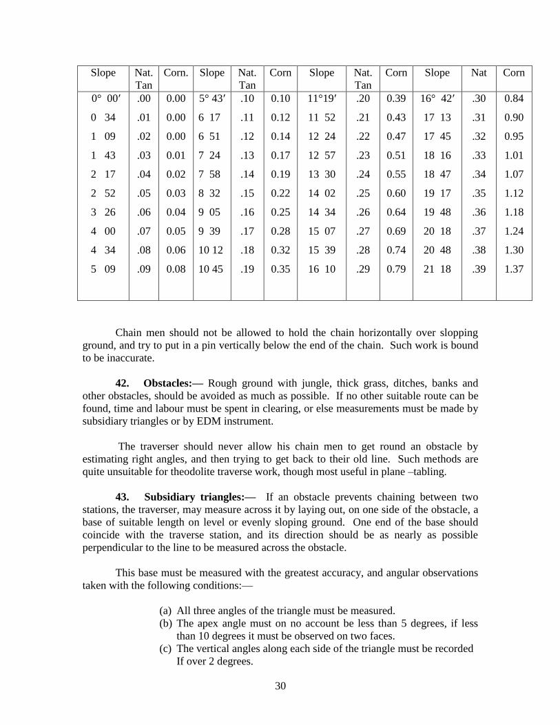
The necessary corrections to the distances can be made later from the table given
on next page or worked out from the formula:
Correction to 1 short chain = 20 (1-cos θ ) = 20 versine θ metres, θ being the
angle of the slope. This correction is always to be subtracted from the measured
distance.
For work on 1:50,000 and smaller scales, slopes flatter than 2 degrees will not affect
the work and may be ignored.
Major E. A. Tandy suggests the use of a staff with clinometer graduated in ‗versines‘
called a versine staff.
The expression (1-Cos θ) used above is called versine θ , and an instrument could be
graduated to show 20 versine θ instead of degrees or natural tangents, for any observed
slope. The observer would record in his field book the quantity read on the instrument
and this multiplied by the measured distance in chains, gives the corrections to be
subtracted from the measured distance.
Any rough clinometer could be so graduated and mounted on a staff and used with a
forward staff of a same height. The simplicity of reading and calculation is specially
valuable in a long line of varied slopes, for readings can be taken rapidly at frequent
intervals notings, measured distances and readings of 20 versine. When heights of
stations are not required for topographical purposes, it is then unnecessary to read any
vertical angles by theodolite at all. Tables of natural versines for al angles are given in
Chambers‘s Mathematical Tables and in 22 C Math. of part II of the Auxiliary Tables.
Reduction to horizontal of chain measurements on a slope
Correction to one chain (20 metre)
(Always to be subtracted)
30
Slope Nat.
Tan
Corn. Slope Nat.
Tan
Corn Slope Nat.
Tan
Corn Slope Nat Corn
0° 00′
0 34
1 09
1 43
2 17
2 52
3 26
4 00
4 34
5 09
.00
.01
.02
.03
.04
.05
.06
.07
.08
.09
0.00
0.00
0.00
0.01
0.02
0.03
0.04
0.05
0.06
0.08
5° 43′
6 17
6 51
7 24
7 58
8 32
9 05
9 39
10 12
10 45
.10
.11
.12
.13
.14
.15
.16
.17
.18
.19
0.10
0.12
0.14
0.17
0.19
0.22
0.25
0.28
0.32
0.35
11°19′
11 52
12 24
12 57
13 30
14 02
14 34
15 07
15 39
16 10
.20
.21
.22
.23
.24
.25
.26
.27
.28
.29
0.39
0.43
0.47
0.51
0.55
0.60
0.64
0.69
0.74
0.79
16° 42′
17 13
17 45
18 16
18 47
19 17
19 48
20 18
20 48
21 18
.30
.31
.32
.33
.34
.35
.36
.37
.38
.39
0.84
0.90
0.95
1.01
1.07
1.12
1.18
1.24
1.30
1.37
Chain men should not be allowed to hold the chain horizontally over slopping
ground, and try to put in a pin vertically below the end of the chain. Such work is bound
to be inaccurate.
42. Obstacles:— Rough ground with jungle, thick grass, ditches, banks and
other obstacles, should be avoided as much as possible. If no other suitable route can be
found, time and labour must be spent in clearing, or else measurements must be made by
subsidiary triangles or by EDM instrument.
The traverser should never allow his chain men to get round an obstacle by
estimating right angles, and then trying to get back to their old line. Such methods are
quite unsuitable for theodolite traverse work, though most useful in plane –tabling.
43. Subsidiary triangles:— If an obstacle prevents chaining between two
stations, the traverser, may measure across it by laying out, on one side of the obstacle, a
base of suitable length on level or evenly sloping ground. One end of the base should
coincide with the traverse station, and its direction should be as nearly as possible
perpendicular to the line to be measured across the obstacle.
This base must be measured with the greatest accuracy, and angular observations
taken with the following conditions:—
(a) All three angles of the triangle must be measured.
(b) The apex angle must on no account be less than 5 degrees, if less
than 10 degrees it must be observed on two faces.
(c) The vertical angles along each side of the triangle must be recorded
If over 2 degrees.
31
It is most important to give a diagram of the subsidiary triangle in the field book. The
diagram should be marked so clearly that the computer will have no difficulty in
recognizing which distance to use in the set up.
44. Tidal Creeks: In taking a traverse line over very bad country, across wide
rivers or along tidal creeks as in the Sundarbans where accurate chaining is impossible
and jungle is thick, a combination of triangulation, EDM and chaining can be adopted,
one method helping the other. Chaining would be used whenever the ground was at all
good, and the triangular measurements would carry one base on to the next, making
stations on both banks of the creek.
45. The field book: A Specimen field book, 2 Trav. on a reduced scale, is shown
on Plate II from which the method of making entries may be seen. The following rules
will be useful as a general guide:
(a) All en entries in the field book are to be made on the spot in ink. A common
lead pencil should never be used.
(b) No erasures whatever may be made in the field book. All figures corrected, or
altered, must be initialled.
(c) No second copy of the field book is to be made for the sake of neatness, except
by the special orders of the Camp Officer and the original will always be kept. under
exceptional circumstances the traverser might find himself forced to record in common
pencil in order to avoid delay, in which case the record must not be touched afterwards in
any way, a copy in ink being made as soon as possible.
(d) Every traverse book will commence with a printed cover 2 (a) Trav. as shown
on Plate I, and must be bound in brown paper to keep it clean. The traverser will himself
fill in all items in this cover.
(e) As a general rule each traverse book will contain one traverse only, and
should be dispatched to the Camp Officer at once on the completion of the traverse.
(f) On the first page a neat diagram must be made showing the starting
connection with the neighbouring triangulated points or traverses (vide specimen field
book plate II) and the mean values of the connecting angles entered as soon as they have
been taken out. First draw the ray to the forward station up the centre of the paper,
between the printed lines, and then holding the book so that this line points in its
direction , draw rays, as nearly as possible as can be done by eye, in their actual position
relatively to this line, to the different triangulated points and traverse stations with which
it is intended to form a connection. Similarly a closing diagram must be made at the end
of each traverse commencing with the back ray.
(g) A line should be drawn right across the page above the chain or steel band
measurement between two stations, the forward station number being entered just above
this line.
32
(h) A heavy line right across the page must be made at the conclusion of each
day‘s work, and a new date entered above it when work is continued next day (vide
specimen field book Plate II).
(i) When recording the vertical readings, an arrow should be drawn as shown in
the specimen, as this facilitates reading the book.
(j) The traverser must compare his field book very carefully with his chart before
he sends it in to headquarters, and see that all points are numbered correctly and that
references to right and left of the traverse line are entered on the correct side; in all
diagrams, station numbers, distances, and observed angles should be so entered that there
can be no doubt as to what each entry refer to.
(k) The traverser should mark with a red P, points or stations which are sure to be
useful to plane-tablers, and are likely to be found for more than 10 years.
(l) Descriptions of intersected and offset points must be clear, and the position and
method of marking each traverse station should be described.
I Trav. headed ―Main Circuit Field Book‖ is sometimes used by topo traversers.
It is ruled with thick lines that only allow four entries above each other against
each station. There is not, therefore room for the entry of many offsets, though there is
ample room in the margins for intersected points and diagrams. When using this form it
should be particularly noted that the distance entered directly opposite a station is the
distance between the station and its back station.
Rules as to checking the field book are given in para 57.
A traverser should generally not be allowed to proceed on leave till his field book
has been completely checked, and the set up entered and proved.
46. Marking of Traverse Stations: Every traverse station must be marked as
Conspicuously as possible, for unless a plane tabler can find two or more consecutive
stations, he cannot properly identify his position or orientate his board. Every fifth
station is usually distinguished by an extra large cairn of stones or by some special mark.
When a peg is used as the station mark, a V-shaped trench should be cut on either side of
it, partly to indicate the exact position of the peg, and partly to show the direction of
adjoining stations. In rocky ground when a 0 is used, the mark should be cut and not
merely scratched on the surface, and if possible a small cairn of stones erected over it.
Whenever forest pillars exist, stations should be selected as close as possible to them, and
the actual position of the pillar recorded in the field book by an offset. When pegs are
used, they should be driven nearly flush with the ground, as both horizontal and vertical
measures are referred to the top of the peg and not to the ground itself. In forest surveys
it is customary to drive in stout posts to mark stations, and as the distances between them
are short, it is necessary to drive a small iron pin into the top of each post, so as to define
the point to which horizontal measures are taken.
33
When traverse lines follow roads and pass through populated districts, a large
proportion of the station marks and pegs are destroyed very soon after and it is only a
small proportion that can be identified the following season. In jungle districts also,
stations are lost by growth of jungle, destruction by wild animals, heavy rains and floods.
The traverser should, therefore, take particular pains to make a large number of
his station marks in positions that will last for several years, and he should distinguish
such stations in his field book and on his chart. Such well-marked stations might be on or
near a bridge, culvert, milestone, road crossing or even at the foot of a large tree. Precise
description should be entered of such stations, giving the exact distances of the mark to
easily recognizable points close by. In forest areas it is not sufficient to drive in a peg
and give the distances to neighbouring trees.
The following devices have been used for marking traverse stations:-
(a) Wooden pegs driven at least 45 cm into the ground.
(b) Cairn of stones at least 60 cm high, built over peg.
(c) Mound of earth at least 75 cm high, built over peg.
(d) Peg protected by sheet of kerosene oil tin hammered round it.
(e) Iron or clay pipes used as pegs; the pipes are filled with charcoal or
red brick dust which remains even if the pipes are removed.
(f) A useful mark is an inverted bush buried so that its stem serves as a
peg, whilst the buried crown prevents easy removal and is a sure
marks if found later.
(g) A satisfactory way of making a permanent mark is to drive a long
wooden stake at least 45 cm into the ground and place over it a
bottomless basket about 60 cm in diameter and height. Fasten the
basket firmly to the stake, fill in with earth, and plant in it the shoot
of a papal tree.
When passing through villages it is a good plan to entrust some of the marks to
certain villagers, and write the names of these men down in the field book. As a rule the
villagers are rather proud of the trust, and will point out the marks to the plane-tabler
several years later.
All traverse stations should have their descriptions and positions clearly entered in
the field book, so that the plane-tabler may find them later on, and this description must
be copied later into the set up and the field plots or plane-table sections.
47. Fixing points by offset: - The main object of a theodolite traverse is to
provide control for plane-tabling or air survey. For plane-tabling the objects should have
a good silhouette, such as a temple, and for air survey a strong orthogonal definition, such
as a corner of a playing field, track junction etc. The actual traverse stations may not
satisfy these conditions. Therefore, a traverser will have to fix a number of such points as
he goes along, either by intersection or by offset.
34
To fix points by offset, the traverser records in his field book the chainage along
his line wherever he crosses a stream or road or passes close to an object that will be
easily recognized by the plane-tabler, he also records the distance to the right or left of
the traverse line at which the point lies. He takes these measurements from the tindal in
charge of the short chain, which he should accompany himself when moving from one
station to the next; he should not enter any point that he has not noticed himself.
Points which lie within five chains of the traverse line can be recorded without
specially setting up the theodolite, but if a point lies at such a distance from the traverse
line that an error in judging the right angle would affect its plotted position on the scale
of survey, the theodolite should be set up at a suitable point on the line, and the bearing of
the point recorded as well as its distance.
48. Intersected points: Suitable points may be fixed on either side of the
traverse line by intersection from two or more consecutive traverse stations. In flat
country it is seldom possible to fix such points more than 2 kilometres from the line; and
if the country is at all congested or wooded, it is very difficult to make sure of
recognizing the point from more than two consecutive stations.
It is important to mark on the plane-table chart all points observed to; this will
prevent many errors in identification, and greatly assist the computers.
It is not, as a rule, worthwhile observing rays to a point from two traverse stations
between which no direct line has been observed or measured. The computations of such
observations are laborious, and unless the point has been observed from another base, the
results cannot be checked. An exception might be made in the case of an important
conspicuous building of whose identity there can be no doubt.
49. Selection of points: On selecting points for offset of intersection, the
traverser must view the country from the stand point of the plane-tabler and enter such a
description that the plane tabler will have no difficulty in identification. Kilometre stones
or numbered posts of any sort are excellent points to fix; so are temples, culverts, cross
roads, stream junctions or unusual trees. In forest country the traverser has to cut a line
through the jungle, or follow a cleared fire line or path and as a rule a plane-tabler will
have no difficulty in following such a clearing the following season. He will probably
not find many of the traverse stations, but should be able to locate himself at once if he is
given the exact point where every stream cuts the traverse line.
To fix a plan tree in a country covered with palm trees; or to fix one railway
signal near a station where there are several, does not help the plane-tabler in the
slightest.
If the traverser is able to fix sufficient points that can be identified with certainty,
he can spend less time in marking his stations of observation.
35
Point or stations which are sure to be useful to plane-tablers and area likely to be
found in position for more than 10 years should be classed as permanent and marked
with a red P both in field book and chart.
50. Inspection in the field: The Director of GDC / O.C. field wing should
consider it just as important to inspect his traversers in the field as to inspect his plane-
tablers. If he has several traversers at work he should place an officer in direct charge of
them.
If traversers send in their field books and a copy of their chart to headquarters, an
officer can form some opinion of their work by inspecting these; but if a traverser is
doing poor work, this may not appear until computations are well advanced.
An inspecting Officer should look to the following matters when with a traverser:-
i) He should see that the Theodolite is in good working order; he should
observe a round with it himself, as well as watch the traverser at work.
ii) He should check both chains or steel bands and the traverser‘s standard
against his own standard‘ and he should compare these with the entries of
the traverser‘s latest checks.
iii) He should see that the field chart is upto date and complete also that
the connection with old work and with neighbouring traverses is
satisfactory
iv) He should satisfy himself that the traverser has selected the best lines for
his circuits right through his area, and that there will be no gap left with
insufficient points, either inside his area or on the edges of his work.
v) He should walk along a portion of line already completed, see that the
field book is perfectly clear when used on the ground, and that the
traverser has picked up the right sort of points and enough of them. He
should see whether marks at stations are likely to last till the plane-tabler
finds them.
vi) He will work with the traverser on a new portion of line, and watch his
squad at work, especially watching the chain men, and also watching the
traverser using his thedolite, both at ordinary observations and while
observing an azimuth.
vii) If vertical angles are being observed, he should satisfy himself that the
conditions laid down in para 38 are scrupulously adhered to.
viii) He should also check whether the traverser has correctly done the post-
pointing on the air photographs.
A traverser learns far more from a thorough inspection of this sort, than

36
from any amount of coaching at headquarters or reading a textbook.
* * * * *
37
SECTION III.---COMPUTATIONS
51. Order of work.— To reduce the traverser‘s field work to a list of stations
and points with rectangular co-ordinates ready for plotting, the following computations
are necessary:-
( i ) Check the means of all azimuth observations, and compute sun azimuths
on 4 Trav or 7 Lamb and star azimuths on 11 Topo.; for Polaris azimuths
use the form 25 Topo or 8B Lamb. If temperature is not observed, take refraction corresponding to Z.D. from 42 Sur., Part III,
Auxilliary Tables, and neglect parallax (p‖).
( ii ) Check all field books.
(iii ) Prepare a diagram on scale 1:200,000 or ¼ of the scale of survey to
cover the whole area traversed during the
season.
( iv ) Compute all connections made with triangulation.
( v ) Convert such spherical and rectangular co-ordinates as are
necessary, to the new origin of survey.
( vi ) Set up angles and distances from field book on 7 Trav. (set up forms).
(vii ) Enter bearings from old work and azimuths.
(viii) Run down bearings and distribute errors. (Bearings reduced). Stages (i) to (viii) should be carried out as far as possible while work is going on in
the field.
( ix ) Compute Easting and Northiner. Enter these in set up. (Traverses
entered).
( x ) Balance northings against southings and eastings against
westings and distribute errors. (Traverses balanced).
( xi ) Run down final co-ordinates. (Co-ordinates reduced).
( xii) Compute heights on set up form 7 Trav.
(xiii) Compute triangles for all intersected points on 17 Train.
(xiv) Compute co-ordinates of intersected points on 7 and 13 or 14 Trav.
( xv ) Enter in set up description of traverse stations, and also
offset points with their measurements.
In working out traverse computations, angles will be taken to the nearest second.
52. Computation of azimuths.--- All angle books of azimuth observations (3
Topo.) should be sent in to the field computing section month by month, and should be
checked without delay. * Form 14A Trav. using 41 Sur., may alternatively be used for making these computations.
If the traverser has omitted to give any information essential to the computations,
he should be communicated with at once. If any observation fails to prove, reference
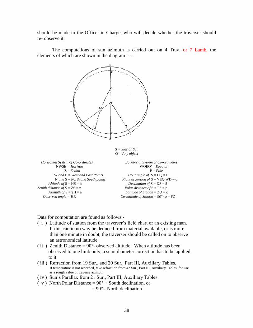
38
should be made to the Officer-in-Charge, who will decide whether the traverser should
re- observe it.
The computations of sun azimuth is carried out on 4 Trav. or 7 Lamb, the
elements of which are shown in the diagram :---
S = Star or Sun
O = Any object
Horizontal System of Co-ordinates Equatorial System of Co-ordinates
NW$E = Horizon WQEQ′ = Equator
Z = Zenith P = Pole
W and E = West and East Points Hour angle of S = DQ = t
N and $ = North and South points Right ascension of S = VEQ′WD = α
Altitude of S = HS = h Declination of S = DS = δ
Zenith distance of S = ZS = z Polar distance of S = PS = p
Azimuth of S = $H = a Latitude of Station = ZQ = φ
Observed angle = HR Co-latitude of Station = 90°- φ = PZ
Data for computation are found as follows:-
( i ) Latitude of station from the traverser‘s field chart or an existing man.
If this can in no way be deduced from material available, or is more
than one minute in doubt, the traverser should be called on to observe
an astronomical latitude.
( ii ) Zenith Distance = 90°- observed altitude. When altitude has been
observed to one limb only, a semi diameter correction has to be applied
to it.
( iii ) Refraction from 19 Sur., and 20 Sur., Part III, Auxiliary Tables. If temperature is not recorded, take refraction from 42 Sur., Part III, Auxiliary Tables, for use
as a rough value of traverse azimuth.
( iv ) Sun‘s Parallax from 21 Sur., Part III, Auxiliary Tables.
( v ) North Polar Distance = 90° + South declination, or
= 90° - North declination.
39
( vi ) Declination of sun or star from Star Almanac for Land Surveyors, a copy of
which for the current year is absolutely necessary. Declination of Sun or Polaris
can be obtained from internet from the ‗www.cadastral.com‘ or any other related
website. Date and time of day should be found recorded in angle book. The
declination of the sun changes so rapidly, that to get an azimuth correct to one
minute, the time of observations should be known correct to a quarter of an
hour ; as it is inadvisable to trust a traverser‘s watch to this extent, the time
should be worked out from the vertical angles observed.
Time may be computed separately on 15 Topo. or a time correction may
be applied to the azimuth computation by the following method devised by Dr. J.
de Graff Hunter :--
Take the declination of the sun at local apparent noon, from the Star Almanac for
Land Surveyors and compute an approximate value of azimuth on 4 Trav.
or 7 Lamb.
EXAMPLE
An azimuth was observed on 1st Jan. 1963 at
λ 20° : 41′ : 08″.23 ( =20.7 degrees )
L 77° : 03′ : 41″.07 ( = 5.1 hours = l)
Declination of the sun on 1st Jan. 1963, at local apparent noon
= declination of sun at G.M.T. 6.92 hrs.
[ = 24-E-l hours ]
= - 23° : 03′ : 19″ [ from Star Almanac for Land Surveyors,
1963, page 2. E from table for argument
(12 – l) hrs. G.M.T.]
Approximate computed Azimuth of sun on 4 Trav., line 22,
Aa = 120° : 57′ : 20″
Now, collecting arguments for Chart, 33 Sur. of Auxiliary Tables
Part III, 8th
Edition.
ζ (Observed) = 64°.6
∆ (90° – declination) = 66°.9 = ( 180° – 113°.1)
Aa (Computed) = 50°.0 = ( 180° – 110°)
λ = 20°.7
Daily change in declination = –288″ (from State Almanac)
Enter Chart with above arguments and obtain δA = +55″.
Aa . Approximate Azimuth = 129° : 57′ : 20″
δA = + 00′ : 55″
_____________________ _____________
Final Azimuth 129° : 58′ : 15″
Particulars for the use of the chart are given on the body of the chart, see Plate V.
Each azimuth is observed on two zeros, and the observations on each zero should
be computed separately. The two results should agree within 15 seconds, and the mean
should be taken.
40
If the results do not agree, a careful scrutiny of the angles observed may show up
an obvious error in one of the readings; the rejection of such a reading may give
satisfactory results.
53. Checking of field books.— As soon as field books are sent in to
headquarters, they will be checked, and if any gross errors or omissions are found, the
Officer-in-Charge should be informed and the traverser told to put them right on the
ground.
As the field books are checked, each figure must be ticked off in red ink, and all
corrections will be made and initialed in the same colour. The examiner will sign and
date the second entry of the cover.
The following points will be attended to:–
( a ) The angular readings at each station described in para 35 will be carefully
examined and their means checked. If the Theodolite has been regularly
set up in the magnetic meridian, gross errors will be readily detected, by
comparing the readings to back and forward stations with their directions
on the field chart.
( b ) The agreement of the two chain measurements will be
checked, and any measurement made along slopes will be converted into horizontal
distances, as explained in para 42. The distance to be used for computation is that
measured with the long chain and this will be clearly distinguished when
checking.
( c ) Subsidiary triangles will be computed.
( d ) The field book will be compared with the field chart, for
correctness of reference numbers to stations and points. All
diagrams should be examined and reference made to the
traverser if they are not perfectly clear.
( e ) The angle book should show clearly how connection is made
with other lines at the initial and closing station of each circuit
or tie-line. Where connection is made with the work of
triangulators or other traversers, that data must be referred to, and
points given in the field book satisfactorily identified.
The field books must be sewn up with each line or circuit in a separate brown
paper cover, and clearly labeled. These must be so left that the correct material for the set
up can be abstracted without difficulty.
54. Computer’s diagram.— A clear diagram is essential to the proper working
and supervision of traverse computations. Many excellent computers have little graphic
41
sense, and follow their work entirely from computation forms. These men cannot deal
with a net work of traverse lines to the best advantage.
A diagram on the 1 : 200,000 or ¼ scale of survey scale should be compiled
directly when copies of the field charts come in. The diagram should cover the whole
area being traversed during the season; it should show all old data to which the new work
is connected. The diagram should be prepared on a suitable rectangular grid of say
10,000-metre squares numbered from the correct origin, and the 15-minute graticule lines
should be drawn on the diagram.
Every traverse line will be shown, distinguished by name and number that must
agree with field book and chart. Each line must be marked with an arrow to show the
direction the traverser followed.
Initial and junction points of every line and all azimuth stations, should be given
their proper numbers.
Intersected and offset points should not be entered, the object of the diagram
being to get the traverse grid or network properly balanced.
Each traverser‘s work may be shown in a different colour ; main circuits should
be drawn in thicker lines than others, and tie-lines in finer lines; the thickening of these
lines should be left till computations have advanced, lest some lines found burdened with
errors.
As computations proceed these will be entered along each line :—
1st— The angular error in each section of the line or circuit,
between azimuths.
2nd
— The closing errors with their signs, in northings and eastings,
in each line or circuit, between initial and closing stations.
3rd
— A specially coloured arrow to denote the direction in which
each line was computed, if opposite to the direction
traversed.
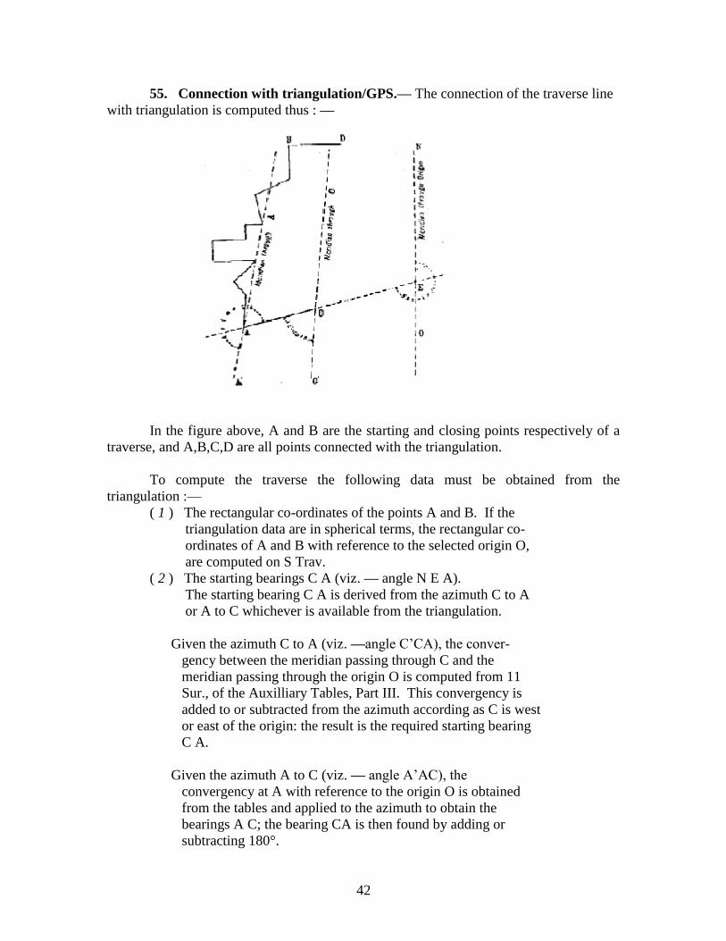
42
55. Connection with triangulation/GPS.— The connection of the traverse line
with triangulation is computed thus : —
In the figure above, A and B are the starting and closing points respectively of a
traverse, and A,B,C,D are all points connected with the triangulation.
To compute the traverse the following data must be obtained from the
triangulation :—
( 1 ) The rectangular co-ordinates of the points A and B. If the
triangulation data are in spherical terms, the rectangular co-
ordinates of A and B with reference to the selected origin O,
are computed on S Trav.
( 2 ) The starting bearings C A (viz. — angle N E A).
The starting bearing C A is derived from the azimuth C to A
or A to C whichever is available from the triangulation.
Given the azimuth C to A (viz. —angle C‘CA), the conver-
gency between the meridian passing through C and the
meridian passing through the origin O is computed from 11
Sur., of the Auxilliary Tables, Part III. This convergency is
added to or subtracted from the azimuth according as C is west
or east of the origin: the result is the required starting bearing
C A.
Given the azimuth A to C (viz. — angle A‘AC), the
convergency at A with reference to the origin O is obtained
from the tables and applied to the azimuth to obtain the
bearings A C; the bearing CA is then found by adding or
subtracting 180°.
43
The bearing may also be computed from the rectangular co-
ordinates of A and C. If these co-ordinates are N, E, N′, E′ the
bearing of ′from A is the angle whose tangent is E′ — E . Here
N′ — N
E′ — E, N′ — N may either or both be positive or negative.
Let θ be the angle such that tan θ = E′ — E without regard to
N′ — N
sign; then,
if E′ – E is + and N′ – N is + the bearing is θ
E′ – E is + and N′ – N is – the bearing is 180° – θ
E′ – E is – and N′ – N is – the bearing is 180° + θ
E′ – E is – and N′ – N is + the bearing is 360° – θ
( 3 ) The closing bearing B D.
The closing bearing B D is found in a similar way to the
starting bearing.
56. Conversion to new origin.— As explained in para 11 the conversion of
points from one system of origin to another must be avoided as far as possible by careful
selection of origin, and by converting such points only as are essential.
The conversion of spherical co-ordinates to rectangular is carried out on S Trav.
Data required . . . . Latitude and longitude of origin.
Latitude and longitude of station to be converted.
Rectangular co-ordinates are converted to spherical on 9 Trav.
Data required.. . . . Latitude and longitude of origin.
Rectangular co-ordinates of station to be converted.
Rectangular co-ordinates are converted from one origin to another on 10 Trav.
Data required. . . . Latitude and longitude of old origin.
Latitude and longitude of new origin.
Rectangular co-ordinates of station to be converted.
Reference should be made to 8 Sur., 9 Sur., and 10 Sur., Part III, Auxiliary
Tables.
57. Set up of angles and distances.— The traverse set up form 7 Trav. requires
careful supervision; it eventually stands as the completed record of the
traverse.
( i ) The traverse diagram is first marked out into main circuits, which are set up
and computed in advance of the other lines. The main circuits should be those which
make the best connections with triangulation / GPS and should for preference follow
roads, railways or open country, where long rays of observation and easy ground for
chaining have been found.
44
The computer need not accept the main circuits marked as such by the traverser.
One main circuit may include lines traversed by more than one traverser, and may run
from one degree sheet into another.
As explained in paras 63 and 65 the computer may have to rearrange the line of a
main circuit if any length is found burdened with large error, either of bearing or position.
( ii ) Take a fresh page of the set up form for each circuit or traverse line.
Fill headings on each page with
Number and name of GDC
Season
Sheet number and page number
Name of traverser
Name and number of circuit
Name of origin and its spherical co-ordinates.
(iii) Now proceed with the set up of the main circuit.
Begin with the point which is best connected with triangulation / GDC, and enter
all stations in serial order, closing with the initial point or some other point well
connected with triangulation.
Draw a thick line right across the page below each junction station, and enter in
the left margin the name of the sub-circuit or tie-line meeting at this station.
Also enter in the left margin the names of all connecting stations and the serial
number of each azimuth station, this serial number referring to the azimuth angle book.
( iv ) Now enter the observed angles and horizontal distances from the field
books.
The observed angle is the mean of the two angular measures described in para
35(g), and is the angle to the left of the traverse line, in the direction followed by the
traverser. It sometimes happens that a traverse line is entered in the set up in the reverse
direction to that followed by the traverser; in this case the computer must enter the reflex
angle(i.e., 360°– observed angle).
The observed angle is entered to the nearest second in the set up, on the same line
as its station of observation.
( v ) Enter the horizontal distance between two stations in the distance column of
the set up, on the same line as the forward station (or back station if the direction of the
line has been reversed).
The distance taken from the field book must have been checked, as described in
para 57(b).
It should be particularly noted that the distance recorded in field book, 1 Trav., in
the same line as the station, is the distance between that station and its back station.
45
58. Bearings.— ( i ) Now enter in red to the nearest second, in the fourth
column of the set up, the bearings derived from triangulation or astronomical azimuths.
The mean observed azimuth is taken from the computation on 4 Trav. And
entered in the left margin. Convergency is calculated from 11 Sur., Part III, Auxiliary
Tables, or from the formula—
Convergency in seconds = Diff. of longitudes in seconds x sin .
To find the bearing, convergency must be added to the azimuth if the station is
west of the origin, and subtracted if east of the origin.
Enter the resulting bearing to the nearest second in the bearing column.
The bearing entered is always that from the back station to the forward, and is
entered in the set up on the same line as the forward station.
Draw a line across the first four columns under each of these fixed or red
bearings, thus dividing the angles of the circuit into compartments.
( ii ) To prove the bearings, sum up all the observed angles page by page, and
take the total for each compartment. If the compartment is a long one, divide the sum on
each page by 360, and only carry forward the remainder. Divide the compartment total
by 360; the remainder should equal the difference between the opening and closing
bearings.
Any discrepancy not greater than 1 minute for every 20 stations, should be
distributed evenly through the compartment. If the discrepancy exceeds a total of 5
minutes, this compartment must be cut out of the main circuit, and treated as a tie-line; or
the traverser must re-observe.
(iii) Now run down the bearings through each compartment.
Beginning at the initial station, add
(the corrected observed angle + 180°) to (the bearing entered on the same line).
Enter this sum (– 360° when necessary) is the bearing column on the next line.
The following alternative rule saves arithmetic:—
Add the corrected observed angle to the bearing entered on the same line.
If the sum is over 180°, subtract 180° to get next bearing.
If the sum is less than 180°, add 180° to get next bearing.
If the sum is over 540°, subtract 540° to get next bearing.
Carry this process down the column to the closing station.
(iv) The same operation should be carried out for each compartment in turn, until
the bearings have been run down for the whole circuit.
(v) Set up forms for sub-circuits and tie-lines are taken up to a similar way, the
bearings of their junctions being taken from the main circuit and treated as opening and
closing bearings.
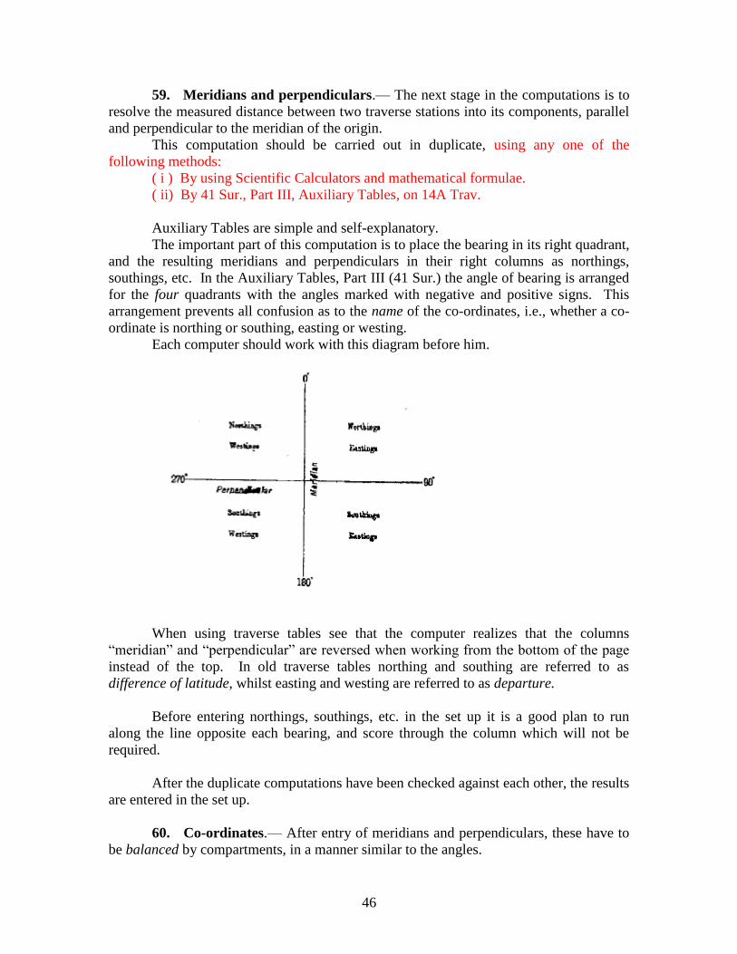
46
59. Meridians and perpendiculars.— The next stage in the computations is to
resolve the measured distance between two traverse stations into its components, parallel
and perpendicular to the meridian of the origin.
This computation should be carried out in duplicate, using any one of the
following methods:
( i ) By using Scientific Calculators and mathematical formulae.
( ii) By 41 Sur., Part III, Auxiliary Tables, on 14A Trav.
Auxiliary Tables are simple and self-explanatory.
The important part of this computation is to place the bearing in its right quadrant,
and the resulting meridians and perpendiculars in their right columns as northings,
southings, etc. In the Auxiliary Tables, Part III (41 Sur.) the angle of bearing is arranged
for the four quadrants with the angles marked with negative and positive signs. This
arrangement prevents all confusion as to the name of the co-ordinates, i.e., whether a co-
ordinate is northing or southing, easting or westing.
Each computer should work with this diagram before him.
When using traverse tables see that the computer realizes that the columns
―meridian‖ and ―perpendicular‖ are reversed when working from the bottom of the page
instead of the top. In old traverse tables northing and southing are referred to as
difference of latitude, whilst easting and westing are referred to as departure.
Before entering northings, southings, etc. in the set up it is a good plan to run
along the line opposite each bearing, and score through the column which will not be
required.
After the duplicate computations have been checked against each other, the results
are entered in the set up.
60. Co-ordinates.— After entry of meridians and perpendiculars, these have to
be balanced by compartments, in a manner similar to the angles.
47
The co-ordinates of fixed points as determined from triangulation or old traverse
work, are entered in red, and mark the opening and closing of the compartment.
The sum of the northings is then balanced against the sum of the southings, and
the difference should agree with that between the north or south co-ordinates of the
opening and closing stations.
The discrepancy should not exceed 1/500 of the total northings added (regardless
of sign) to the total southings (that is 4 metres in 2,000 metres) ; this discrepancy is
distributed between one junction station and the next, in proportion to the sum (regardless
of sign) of northings and southings of each group. In very short lines a large proportional
discrepancy may be accepted.
If the discrepancy in any one compartment exceeds the limits given, the error can
be located by trying alternative routes; the offending length of line will be identified by
the appearance of a similar error in all compartments in which that line is included.
The error so located should at once be noted on the computer‘s diagram and must
never be distributed beyond the terminal points of the line affected. The line in which the
error is located should be cut out of the main circuit and treated as a tie-line; or, if the
error is very big, should be rejected altogether.
Eastings and westings are treated in exactly the same way.
As the arithmetical sum of all meridian (or perpendiculars) is to each particular
meridian (or perpendicular), so is the whole error of meridian (or perpendicular) to the
required correction in meridian (or perpendicular) or in other words, correction in
meridian (or perpendicular) or in other words,
Correction in meridian (or perpendicular) of a line
= – Meridian (or perpendicular) of that line___________ x Total error in
Arithmetical sum of all meridians (or perpendiculars) meridian (or
perpendicular)
Having distributed the errors, the co-ordinates of each station in turn are run down
by applying the northings, eastings, etc., to the co-ordinates of the preceding station.
In entering co-ordinates, care should be taken to enter the letters N, S, E, W, at the
head of each half page, and also at every change from one to another.
61. Heights.— Heights are worked out on set up form 7 Trav. from the
formula—
Diff. of Ht. = Horizontal distance x tan(observed vertical angle).
The ―observed vertical angle‖, used in the computations should be the mean
between reciprocal angles observed at consecutive stations, so that collimation and other
errors may be eliminated.
48
As distances are very short, corrections for refraction are not required.
Heights can be calculated
( i ) by the use of the table for determining heights in traversing.
For table see ―Field Traverse Tables, second edition‖.
( ii ) on 13 Trav. if this is used for computations of northing and
easting.
This differences of height are summed and balanced between fixed heights, a
discrepancy of 20cm in height for one kilometre of horizontal distances being
permissible.
62. Distribution of errors.— A topographical party has not, as a rule, a large
staff of computers ; and traverse computations are generally carried out by the officers
and Topo Auxiliaries who did the traversing in the field, assisted by two or three
computers. With this staff it is generally hard work to get the computations finished in
time for the plotting, which should begin a full month before the field season.
Under these conditions, there is no time for scientific distribution of errors over
the whole traverse network. There is only time for quick and simpler methods of
distribution of errors as described in paras 62 and 64, viz.—
( i ) Select the best lines for main circuits, and keep the worst lines
as tie-lines, or reject them altogether.
( ii ) Distribute by compartments angular discrepancies in direct
proportion to the number of stations.
( iii) Distribute by compartments discrepancies of position
according to the lengths of measured line.
This distribution is quite good enough for ordinary 1 : 50,000 survey.
The object of the computer should be to locate the position of errors made by the
traverser, and to confine them to the locality in which they were made. In the methodical
distribution described in para 67, particular care should be taken that errors already
located as falling in certain lengths of line, are not re-distributed so as to burden more
accurate lines.
The terminal stations of all compartments have so far been treated as fixed points,
whereas their values really depend on an arbitrary distribution of errors inside the main
circuit, i.e., sub-circuits and tie-lines have been forced to close on predetermined points,
which are probably incorrect in their position. Thus such circuits, in addition to their
own errors, are burdened with those of adjoining main and sub-circuits.
It is therefore very desirable to consider the traverse network as a whole, with the
aid of the computer‘s diagram, and endeavour to distribute the errors in such a way as
will reduce the more excessive errors without unduly increasing any of the lesser errors.
Of various methods of distributing errors in use, the simplest and most effective
was devised by Major E.A.Tandy, R.E. and consists in applying corrections to the terminal
points of circuits as described in para 67. It has been used with success in large traverse
networks in the Punjab.
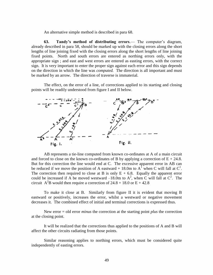
49
An alternative simple method is described in para 68.
63. Tandy’s method of distributing errors.— The computer‘s diagram,
already described in para 58, should be marked up with the closing errors along the short
lengths of line joining fixed with the closing errors along the short lengths of line joining
fixed points. North and south errors are entered as northing errors only, with the
appropriate sign ; and east and west errors are entered as easting errors, with the correct
sign. It is very important to enter the proper sign against each error and this sign depends
on the direction in which the line was computed. The direction is all important and must
be marked by an arrow. The direction of traverse is immaterial.
The effect, on the error of a line, of corrections applied to its starting and closing
points will be readily understood from figure I and II below.
AB represents a tie-line computed from known co-ordinates at A of a main circuit
and forced to close on the known co-ordinates of B by applying a correction of E + 24.8.
But for this correction the line would end at C. The excessive apparent error in AB can
be reduced if we move the position of A eastward + 18.0m to A1 when C will fall at C
1.
The correction then required to close at B is only E + 6.8. Equally the apparent error
could be increased if A be moved westward –18.0m to A2, when C will fall at C
2. The
circuit A2B would then require a correction of 24.8 + 18.0 or E + 42.8
To make it close at B. Similarly from figure II it is evident that moving B
eastward or positively, increases the error, whilst a westward or negative movement
decreases it. The combined effect of initial and terminal corrections is expressed thus.
New error = old error minus the correction at the starting point plus the correction
at the closing point.
It will be realized that the corrections thus applied to the positions of A and B will
affect the other circuits radiating from those points.
Similar reasoning applies to northing errors, which must be considered quite
independently of easting errors.
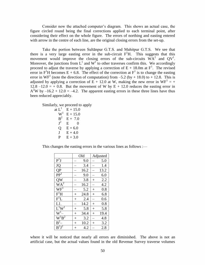
50
Consider now the attached computer‘s diagram. This shows an actual case, the
figure circled round being the final corrections applied to each terminal point, after
considering their effect on the whole figure. The errors of northing and easting entered
with arrow in the centre of each line, are the original closing errors from the set-up.
Take the portion between Sultānpur G.T.S. and Mahitpur G.T.S. We see that
there is a very large easting error in the sub-circuit F1H. This suggests that this
movement would improve the closing errors of the sub-circuits WA2 and QV
1.
Moreover, the junctions from L1 and W
1 to other traverses confirm this. We accordingly
proceed to adjust the traverse by applying a correction of E + 18.0m at F1. The revised
error in F1H becomes E + 6.8. The effect of the correction at F
1 is to change the easting
error in WF1 (note the direction of computation) from –5.2 (by + 18.0) to + 12.8. This is
adjusted by applying a correction of E + 12.0 at W, making the new error in WF1 = +
12.8 –12.0 = + 0.8. But the movement of W by E + 12.0 reduces the easting error in
A2W by –16.2 + 12.0 = –4.2. The apparent easting errors in these three lines have thus
been reduced appreciably.
Similarly, we proceed to apply
at L1 E + 15.0
W1 E + 15.0
B2 E + 7.0
J2 E 0
Q E + 6.0
J E + 4.0
P E + 3.0
This changes the easting errors in the various lines as follows :—
Old Adjusted
P1J – 9.0 – 5.0
JQ – 3.4 – 1.4
QP – 16.2 – 13.2
PP1 – 9.0 – 6.0
QW – 3.8 + 2.2
WA2 – 16.2 – 4.2
WF1 – 5.2 + 0.8
F1H + 24.8 + 6.8
F1L + 2.4 – 0.6
L1– – 14.2 + 0.8
L1W
1 + 5.8 + 5.8
W1– + 34.4 + 19.4
W1B
2 + 3.2 – 4.8
B2– + 10.2 + 3.2
B2J
2 + 4.2 – 2.8
where it will be noticed that nearly all errors are diminished. The above is not an
artificial case, but the actual values found in the old Revenue Survey traverse volumes
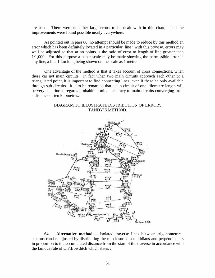
51
are used. There were no other large errors to be dealt with in this chart, but some
improvements were found possible nearly everywhere.
As pointed out in para 66, no attempt should be made to reduce by this method an
error which has been definitely located in a particular line ; with this proviso, errors may
well be adjusted so that at no points is the ratio of error to length of line greater than
1/1,000. For this purpose a paper scale may be made showing the permissible error in
any line, a line 1 km long being shown on the scale as 1 metre.
One advantage of the method is that it takes account of cross connections, when
these car not main circuits. In fact when two main circuits approach each other or a
triangulated point, it is important to find connecting lines, even if these be only available
through sub-circuits. It is to be remarked that a sub-circuit of one kilometre length will
be very superior as regards probable terminal accuracy to main circuits converging from
a distance of ten kilometres.
DIAGRAM TO ILLUSTRATE DISTRIBUTION OF ERRORS
TANDY‘S METHOD.
64. Alternative method.— Isolated traverse lines between trigonometrical
stations can be adjusted by distributing the misclosures in meridians and perpendiculars
in proportion to the accumulated distance from the start of the traverse in accordance with
the famous rule of C.F.Bowditch which states :
52
‗As the sum of all the distances is to each particular distance so is the total error
for meridian (or perpendicular) to the required correction for meridian (or
perpendicular).‘
i.e., correction to meridian (or perpendicular) of a line
= _____– length of that line_____ x Closing error in meridian
Total length of the traverse (or perpendicular)
In these method the angular errors from observed bearings are not to be adjusted
before applying this rule. Difficulties, however, arise when adjusting a network of
traverses where the junction points are not predetermined trigonometrical stations or
points. It is generally noticed that the adjusted values of the common point from different
traverse lines differ considerably.
Co-ordinates should be computed for the common points from both ends of the
lines connecting it. Weights proportional to the reciprocal of the accumulated distance
from the end stations should be assigned to these values and weighted mean co-ordinates
accepted for the common point. The residual discrepancies should be distributed over the
different sections, according to the Bowditch rule.
65. Intersected points.— The computation of intersected points can be pushed
on before the completion of the set up.
First, the triangles are worked out on 17 Trian. by Scientific calculators, taking all
data from the field book.
When triangles are completed, co-ordinates are worked out on 7 Trav.; this stage
must wait until the set up has been finally balanced and proved.
If the field book is untidy and difficult to read, great care must be taken in
verifying the stations from which each ray is observed, and in taking out the correct
bases, angles and bearings.
When a point, observed from more than two stations, fails to prove, reference
should be made to the field chart; if the angles taken from the field book are then laid out
on the chart with a protractor the computer can probably detect some error and arrive at a
solution.
When working out co-ordinates, the same precautions should be taken as are
described in concerned para, and as a final check, the computed position of each
intersected point should be compared with its position on the field chart.
66. Offset Points :- For field work the majority of offset points can be taken
straight from the field book, either being plotted direct on to a field plot, or else being
copied on to a list thus :-
53
To prepare list of offset points with rectangular co-ordinates, the quickest way is to plot
on a large scale, on 4 Sec. (28 Trav. renumbered) or other squared paper, the pairs of
traverse stations between which each offset point lies. Then find position of offset points
graphically from the measurements given in the field book, and read off the co-ordinates
required.
In the case of an offset point more than 200 metres from the line, to which the
traverser had observed a bearing, it would be necessary to compute the position of the
point on 7 Trav. In this case the point should be included with the intersected points.
67. Projection and plotting of field work.— The plotting of traverse work is
not nearly so simple as plotting triangulation. There are far more points to be plotted, and
they are of such different kinds, that full descriptions have to be given of all. The stations
are plotted from the set up, intersected points from 7 Trav., and offset points direct from
the field book. With a competent Officer-in-Charge of the plotting section, allow two
men a full month for every dozen field sections.
If the area allotted to each plane-tabler is reasonably large, it is convenient to plot
the traverse points directly on the plane-table sections. If, on the other hand, there are
several plane-tablers allotted to one sheet, and there is a chance of having to plot extra
boards in the same area, it saves time and labour to plot the traverse points on a special
plot, and prick through to the several plane-table sections.
The plot should be on bankpost or light drawing paper and should as a rule cover
a full sheet of the scale of survey.
The plots as well as the plane-table sections, should be ruled with rectangular
grids as per requirement.
The
lines of the
rectangular grid are numbered in both directions so as to cover the area required; with the
distinctive letters N, S, E, W, in front of each number.
Offsets
Stations
Meridians
Perpendiculars
At chainagae 18, 20, 40m
right . . . .
Kilometre stone 15 . .
f1
g1
N. 247.3
N. 254.1
E. 1006.4
E. 974.2
Offsets
Stations
Meridians
Perpendiculars
54
As plane-tablers normally work to spherical graticules, the corners of the
spherical graticule are now plotted from 12 Sur., Part III, Auxiliary Tables; the spherical
graticule is ruled up and figured in black ink. As a rule the rectangular grid is ruled and
figured in blue.
It is sometimes necessary to project a rectangular grid on to a sheet already drawn
with spherical graticule. In this case, find the rectangular co-ordinates of the outer four
corners A, B, C, D, of the spherical graticule from 12 Sur., Part III, Auxiliary Tables, or
by computation on form 8 Trav. if table 12 Sur. does not refer to the correct origin. Then
take the four corner points A′,B′, C′, D′, of the rectangle which are nearest the spherical
figure A B C D, the rectangular co-ordinates of A′, B′, C′, D′, being multiples of 100.
Then convert A′, B′, C′, D′, from rectangular to spherical co-ordinates on 9 Trav. and
plot them by scale from the spherical graticule; join them up to form a rectangle, and sub-
divide this rectangle into the grid required. This should be checked by re-plotting A, B,
C, D, by the rectangular co-ordinates given in 12 Sur., Part III, Auxiliary Tables.
Where there are several rectangular systems with different origins to be projected
with the same spherical graticule, care must be taken that the corners of each separate
rectangular system are converted to spherical values as described in the previous sub-para
and that these spherical values are used for plotting the corners A˝, B˝, C˝, D˝, &c., from
the graticule corners ABCD.
All projections must be checked independently, and must be initialed by the
supervising officer before plotting proceeds.
The traverse stations are plotted from their co-ordinates in the set up, and then
checked independently by their distances apart. They are inked up in small blue circles,
and are joined up by straight lines, also in blue, being thus distinguished from other
points.
The intersected points are plotted from co-ordinates in 7 Trav. and after check are
inked up in small blue circles.
The offset points are plotted direct from the field book, and should be shown by a
blue dot with description. On the plot, full descriptions should be given to all stations
and points, and all information given in the field book that could possibly help the
planetabler, should be entered in the plot. For instance, if the field book shows that the
traverse line followed a road or bund, this should be entered on the plot.
When the plot is completed, it should compared with the field charts, and any
errors or omissions rectified. In dealing with traverse computations, it is quite likely to
overlook a whole line, or a whole page of intersected points; north points may be plotted
as south points, or a point may be plotted in the wrong square. Such errors can easily be
overlooked when checking from computations, but strike the eye at once if compared
with a chart.
Triangulated and traverse points from other surveys, that might help the plane-
tabler, must also be plotted, and this may have to be done by laying down a grid based on
55
another origin. This grid and the points plotted from it should be inked up in a distinctive
colour.
The plot should be initialed by the supervising officer when completed, and
should also be inspected by the Officer-in-Charge of the party.
The plots will then be pricked through to the several plane-table sections, which
should be checked against the original computations before being inked up. Each plane-
tabler should be given all points up to 2 kilometres beyond the limits of his work.
To avoid crowding, certain symbols, such as trees, culverts, roads, etc., may be
drawn in blue, instead of entering descriptions.
Each plane-tabler should be given a trace of the plot to cover his area and this
trace should give full information and all descriptions. It is great waste if a place-tabler
fails to identify points, which the traverser has described with care in his field book, just
because that information has never been passed on to the plane-tabler.
The original traverse plots should be kept by the Camp Officer during the field
season, and original computations should not be allowed to leave party headquarters. If
new plane-tables have to be prepared in the field, the Camp Officer can prick through the
data from his plot.
If preferred, points may be transferred by dividers instead of being pricked
through.
As an alternative to giving the traverse plot to the Camp Officer, and a trace of it
to the plane-tablers, lists of stations, intersected and offset points, with full descriptions,
may be abstracted from the computations.
68. Traverse record volumes.— When the traverse computations are completed
ready for plotting, the results are scattered over many bulky forms.
The only parts of these that are required for future reference and record are the set
up forms, with list of permanent offset and intersected points, with their co-ordinates, and
an adequate diagram or chart. The set up should be bound as a record volume covering
all traverse work in one degree sheet, and should be entered up with all useful
information and data from the field books.
First— All descriptions of stations that can be well identified, should be entered
against the station on the left of the set up thus :—
d′ N.W. corner of cross roads Hijli to Noina, Bamra to Harua.
e′ on road opposite footpath to Deganga.
f′ Mosque 50 metres, bearing 25°.
g′ Forest B.P. No. 26, S.E. 10 metres.
56
Second— Enter data of all the more important offset points, on the right of the set
up.
Third— All stations and points that can be well identified, and are likely to be
found in position for more than 10 years should be marked clearly with a red P.
The record volume should also contain,
( i ) An Index, giving season, name of traverser, nomenclature of
each circuit, number of map sheet in which each circuit falls,
and page of volume on which it will be found.
( ii ) A list of permanent points, with their rectangular co-ordinates.
(iii) A history sheet, which should describe the methods and
instruments used, the connections made to triangulation and to
other traverses, the nature of the marks and points fixed, with
a general description on the country. An abstract should be
given showing the average errors found on computing the
traverse and also the greatest errors found in any line. The
errors of the main circuits should be given separately from
the errors of the whole work.
( iv ) A copy of the computer’s diagram, which should be ruled to
show the limits of 1 : 50,000 sheets.
The volume should have a clear label pasted on the front cover, stating—
Degree sheet,
Origin,
Number and name of Party,
Name of traverser,
Season.
The following is a suitable order for arranging a Traverse Record Volume—
Label,
Contents,
History sheet,
Index,
List of permanent points,
Computations of connections to triangulation,
Set up,
Computer‘s diagram,
Traverse record chart.
69. Traverse record charts.— A record chart on the 1 : 250,000 scale should
be prepared for each degree sheet, and should subsequently be combined with the
triangulation chart.
The record chart should show :—
( i ) All triangulation stations, GPS stations and permanent
triangulated points in the area traversed, entered in
black.
( ii ) All traverse lines which follow a prominent feature
57
such as railway, road, or river bank.
(iii ) Selected traverse stations, intersected and offset
points, which have been classed as permanent, entered
in blue.
The selected traverse stations which fall on the lines shown under item (ii), will
be joined together by blue lines, whilst the feature they follow will be indicated in red or
black.
A list will be attached to the chart, giving the description and spherical co-
ordinates of all stations and points shown.
70. Disposal of traverse records.— Original traverse records will be disposed of as
under :—
A— To be destroyed after completion of the traverse record volume.
( i ) Observations for azimuths.
( ii ) Field books.
( iii ) Computations of azimuths.
( iv ) ˝ ˝ conversions of co-ordinates.
( v ) ˝ ˝ meridians and perpendiculars.
( vi ) ˝ ˝ intersected points.
B— To be destroyed after completion of the traverse record chart.
(vii ) Field charts.
C— To be embodied in the traverse record volume.
(viii) Computation of connections to triangulation.
( ix ) Set up.
( x ) Computer‘s diagram.
71. Transfer outside the department of departmental original records.— The
transfer outside the department of departmental original records is forbidden except with
the express approval of the Surveyor General.
With the approval of the Additional Surveyor General / Director of GDC
concerned, however, such records may be shown to non-Survey of India authorities who
require to see them in the execution of their duties.
58
SECTION - IV
TOTAL STATION – PRINCIPLE AND APPLICATIONS
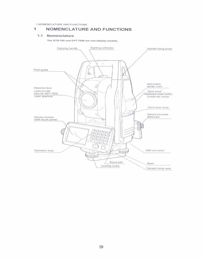
59
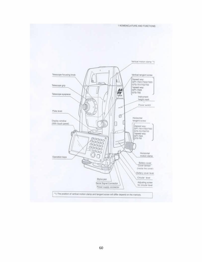
60
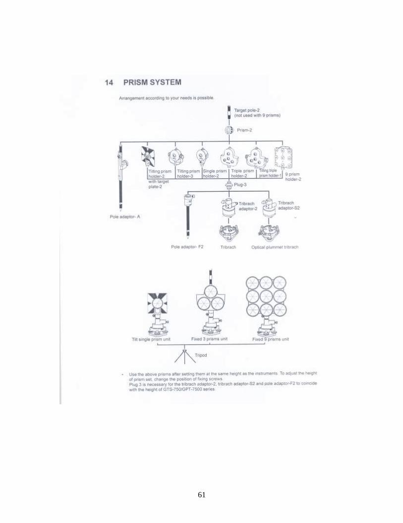
61
62
1. TOTAL STATION INSTRUMENT :-
The Total Station is an electronic digital instrument consisting of the following :-
a) Distance measuring device (EDM).
b) Angle measuring device (Theodolite).
c) An inbuilt micro processor device with suitable software loaded in it.
d) The instrument has also a Memory Card to store the field data.
2. WORKING PRINCIPLE OF TOTAL STATION :-
With known co-ordinate of the instrument position and a known bearing of back
station (ordinate) the co-ordinates of any other point can be computed from Total Station
observation. To start with Total Station, the essential requirements are :-
a) When two points are known.
b) When only one point is known, the bearing of back station is also known.
c) When no co-ordinates were given in which case arbitrary system of
coordinates is used.
The instrument can automatically measure horizontal and vertical angles, slope
distances, horizontal distance and height difference from a single set up. From these
data they can instantaneously compute elevations and coordinates of the target station and
display the results on LCD.
The instrument also stores the data, either on board or in external data collectors.
Total Stations offer many advantages for almost all types of surveying. They are
used for topographic, hydrographic, cadastral, project and construction surveys.
The EDM instrument component installed in a Total Station is relatively small but
still has distance ranges adequate for most work. Lengths about 2 km can be measured
with a single prism, and about 6 to 7 km with triple prism and 9 – prism.
3. FUNCTIONS PERFORMED BY TOTAL STATIONS :-
63
Total Stations, with their micro processors, can perform, a variety of functions
and computations, depending on how they are programmed. The capabilities vary with
different instruments, but some standard computations include
a) Averaging multiple angle and distance measurements.
b) Correcting electronically measured distances from prism constant,
atmospheric pressure and temperature.
c) Making curvature and refraction corrections to elevations determine by
trigonometric leveling.
d) Reducing slope distances to their horizontal and vertical components.
e) Calculating point elevations from the vertical distance components
(supplemented with keyboard input of instrument and reflector heights)
f) Computing coordinates of survey points from horizontal angle and
horizontal distance components.
4. APPLICATIONS OF A TOTAL STATION :-
The Total Station can be used for the following purposes also :-
i) Control Survey (Traverse).
ii) Detail Survey i.e., data collection.
iii) Height measurement (Remove Elevation Measurement).
iv) Remote Distance Measurement (RDM) or Missing Line Measurement
(MLM).
v) Fixing of missing pillars (or) setting out (or) stake out.
vi) Resection.
vii) Area calculations, etc.
i) Control Survey / Traverse :
It is similar to any type of EDM Traverse.
Work at the first station :
64
a) Erect the tripod stand at the known starting station vertically with the help
of plumb bob.
b) The instrument is leveled as usual in the same way as in the traditional
method of theodolite.
c) The Instrument is powered on. Check the battery status on the first
screen.
d) In the instrument ― Main menu screen appears‖.
e) Check the digital level by pressing shift + F12 (Leica) and ensure that the
level is with in 10 seconds in both X-axis and Y-axis. Otherwise with the
help of leveling screws bring the level within 10 seconds.
f) Come back to MAIN MENU.
g) Follow the steps as in SOP for LEICA 1100 series and 1200 series
supplied.
h) Now, SET or CONFIRM the parameters such as in Config Set.
Distance units
Angle Units
Tolerances
T & P Correction
Instrument constant or Prism constant
Projection correction or Scale factor
Sea level correction
C & R Correction
C & R Coefficient
Coordinate mode, order and number of decimal points
i) Once the above parameters are selected as per the requirement, the
instrument is ready to begin with the work.
(Work at the subsequent stations repeat the steps 1 to 6 only as per
the SOP of LEICA 1102 / 1103 / 1202)
65
j) The traverse is carried out as per the traditional method of theodolite
traverse following the on screen prompts (if necessary by using the SOP
provided) keeping the following points in mind.
Full details such as Station No, ID, HT of Instrument, Temperature
and Pressure at the time of observation, BS Stn No, ID, HT of Target
etc., are correctly entered at each station of observation.
Traverse angles are measured in two sets.
After completion of two sets, calculation is performed.
After closing the traverse, the traverse adjustment is carried out
using the function available within the instrument / Leica Geo Office
/ LISCAD SW (Procedure may be followed from SOP).
The adjustment report is noted down / printed as a record before co-
ordinates been updated.
The traverse adjustment accuracy should not be less than 1:10,000
(this will vary according to the requirement, scale of survey etc.).
Data Collection Option : (2000 – 4000 Points) Measurements can be stored ―On
Board‖ with all the Total Stations. The two options that are available are :-
a) Data can be stored directly in the memory of the micro computer and later
down loaded to an external storage device via a RS – 232 connections.
b) The second option is the removable memory card. When one card is full,
it can be removed and another card can be quickly installed.
ii) Detail Survey :-
Given two points whose coordinates are known, a total station can be used to get
the coordinates of various other points based upon these two co-ordinates. Care should
be taken that the new point survey are carefully coded.
TR – Tree, EP – Electric Pole, RD – Road, BD – Building Corner etc.
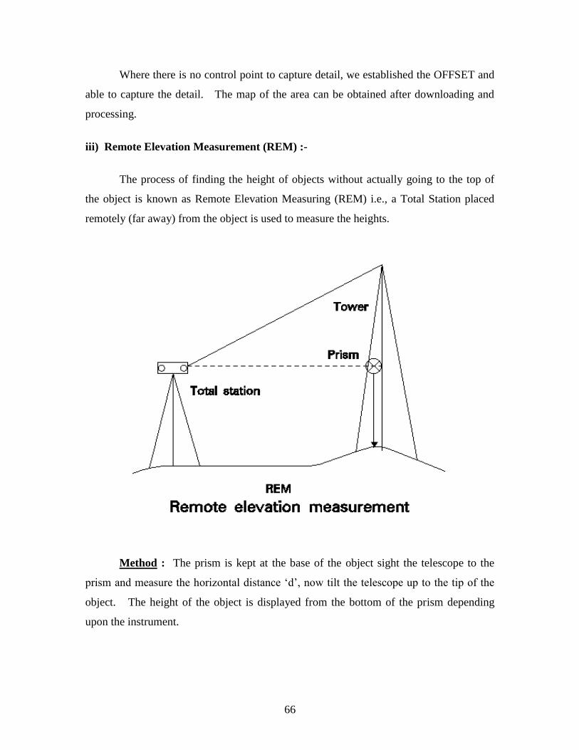
66
Where there is no control point to capture detail, we established the OFFSET and
able to capture the detail. The map of the area can be obtained after downloading and
processing.
iii) Remote Elevation Measurement (REM) :-
The process of finding the height of objects without actually going to the top of
the object is known as Remote Elevation Measuring (REM) i.e., a Total Station placed
remotely (far away) from the object is used to measure the heights.
Method : The prism is kept at the base of the object sight the telescope to the
prism and measure the horizontal distance ‗d‘, now tilt the telescope up to the tip of the
object. The height of the object is displayed from the bottom of the prism depending
upon the instrument.
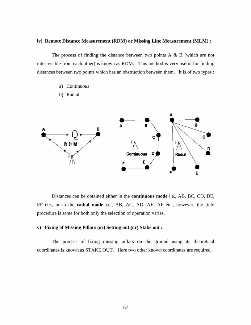
67
iv) Remote Distance Measurement (RDM) or Missing Line Measurement (MLM) :
The process of finding the distance between two points A & B (which are not
inter-visible from each other) is known as RDM. This method is very useful for finding
distances between two points which has an obstruction between them. It is of two types :
a) Continuous
b) Radial
Distances can be obtained either in the continuous mode i.e., AB, BC, CD, DE,
EF etc., or in the radial mode i.e., AB, AC, AD, AE, AF etc., however, the field
procedure is same for both only the selection of operation varies.
v) Fixing of Missing Pillars (or) Setting out (or) Stake out :
The process of fixing missing pillars on the ground using its theoretical
coordinates is known as STAKE OUT. Here two other known coordinates are required.
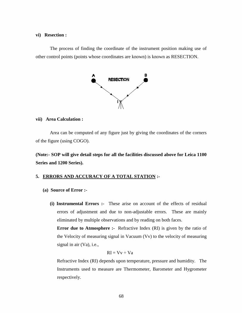
68
vi) Resection :
The process of finding the coordinate of the instrument position making use of
other control points (points whose coordinates are known) is known as RESECTION.
vii) Area Calculation :
Area can be computed of any figure just by giving the coordinates of the corners
of the figure (using COGO).
(Note:- SOP will give detail steps for all the facilities discussed above for Leica 1100
Series and 1200 Series).
5. ERRORS AND ACCURACY OF A TOTAL STATION :-
(a) Source of Error :-
(i) Instrumental Errors :- These arise on account of the effects of residual
errors of adjustment and due to non-adjustable errors. These are mainly
eliminated by multiple observations and by reading on both faces.
Error due to Atmosphere :- Refractive Index (RI) is given by the ratio of
the Velocity of measuring signal in Vacuum (Vv) to the velocity of measuring
signal in air (Va), i.e.,
RI = Vv ÷ Va
Refractive Index (RI) depends upon temperature, pressure and humidity. The
Instruments used to measure are Thermometer, Barometer and Hygrometer
respectively.
69
Prism Constant :
Prism : Prisms are used with Electro Optical or EDM to get reflect the
transmitted signals. The single reflector is a cube corner prism. That has the
characteristic of reflecting light rays, back precisely in the same direction as
they are received. Due to the difference in the Refractive Index (RI) of the air
and the prism material (glass) the velocity of waves differs resulting in a small
error in distance measurement. This error caused due to the prism is known
as PRISM CONSTANT. Which is provided by the manufacturer generally ?
(ii) Errors of Manipulation :-
Defective centering
Defective leveling – error in a direction e tan x where e is a small error
of axis and x is the inclination of the point observed.
Slip tripod head not being screwed firmly, insufficient tightening of
head.
Using wrong tangent screw.
(iii) Observers Errors :-
Inaccurate bisection of signals
Non verticality of signals
Errors due to displacement of pegs or signals
Wrong identification of initial known points
Improper key-in of the coordinates
Improper job parameters settings
Prism constant if using the prism of different make
(iv) Errors due to Natural Causes :-
Wind
High Temperature
Haze
Unequal settlement of Tripod

70
(b) Accuracy of a Total Station :
Accuracy depending upon the instrument and varies from instrument to
instrument.
i) The angular accuracy varies from 1" to 20".
ii) Distance accuracy depends upon two factors.
Instrumental error which ranges from + / - 10mm to + / - 2 mm.
Error due to the length of measurement. It can be from + / - 10mm to +
/ - 2mm per kilometer (prism).
Error due to the length of measurement. It can be from + / - 10mm to +
/ - 3mm per kilometer (reflectorless).
6. USES OF TOTAL STATION :-
As the Total Station can measure distances, horizontal angle, vertical angle and
can compute the coordinates of unknown site quickly. It can be used for the following
applications :-
a) Large scale surveys and mapping for planners
b) All types of engineering projects
c) Cadastral surveys
d) Road, railways, hydro electric project etc.
e) Boundary surveys
f) Mine surveys.
71
STANDARD OPERATING PROCEDURE (SOP)
FOR NIKON TOTAL STATION - 851
A: FIELD OPERATIONS
A: HOW TO SWITCH ON / OFF NIKON DTM 851 TOTAL
STATION
1. PRESS POWER KEY (PWR)
2. TILT THE TELESCOPE TILL THE BEEP SOUND COMES
3. MAIN MENU APPEARS (INSTRUMENT IS ON)
4. TO SWITCH OFF RETURN TO MAIN MENU USING ESC.KEY (ALWAYS BY
PRESSING Esc. KEY BEFORE SWITCHING OFF THE INSTRUMENT)
5. PRESS POWER KEY
6. PRESS ENTER
7. INSTRUMENT IS OFF

72
B: HOW TO CREATE DIRECTORY AND JOB FILE
1. PRESS PWR KEY
2. TILT THE TELESCOPE
3. MAIN MENU APPEARS
4. SELECT JOB MANAGER
5. PRESS ENTER
6. JOB MANAGER WINDOW WILL APPEAR SHOWING ALL THE EXISTING
DIRECTORY AND JOBS
7. SELECT CR DIR TO CREATE NEW DIRECTORY USING SOFT KEY (KEY NO.2-CR
DIR)
8. GIVE THE DIRECTORY NAME (MAXIMUM 8 BITS)
9. PRESS ENTER
10. THE NEW DIRECTORY IS CREATED
11. PRESS CR JOB TO CREATE NEW JOB BY USING KEY 1(CR-JOB)
12. JOB WINDOW WILL APPEAR
13. NAME:…(Give name of the file/job)
DESCRIPTION:…Detail or Traverse (Optional)
CLIENT:……Not Required……(ENTER)…………….
COMMENT:……… Not Required …………(ENTER)…………….………
CONTROL JOB : NONE
14. ENTER
15. MESSAGE ―OPENING THE JOB:………….‖ APPEARS.
16. RETURNS TO MAIN MENU WITH THE NEW SELECTED JOB OPEN.
73
C: STATION SETUP (This operation is performed especially when we have to do Detail Survey in collection mode and
stake out etc)
SELECT STATION SETUP FROM MAIN MENU (KEY NO.2)
PRESS ENTER
STATION SETUP WINDOW WILL APPEAR SHOWING KNOWN STATION, RESECTION,
AND REMOTE BM
SELECT KNOWN STATION FROM THIS WINDOW
PRESS ENTER
KNOWN STATION WINDOW APPEARS ASKING STATION INFORMATIONS
STATION POINT: ……(ENTER THE OCCUPIED STATION NO.)
PRESS ENTER
―POINT NOT FOUND‖ MESSAGE AND WINDOW APPEARS (IF THIS IS A NEW POINT)
ENTER THE ID NUMBER OF THE POINT
PRESS ENTER
ENTER EASTING,
ENTER NORTHING
ENTER HEIGHT
ENTER CODE (OPTIONAL)
PRESS ENTER
POINT RECORDING MESSAGE APPEARS
THE ORIGINAL WINDOW REAPPEARS
ENTER HEIGHT OF THE INSTRUMENT (HI)
PRESS ENTER
ENTER TEMP. ENTER
ENTER PRESSURE, ENTER
74
A KNOWN STATION WINDOW ASKING INFORMATION ABOUT BACK
STATION APPEARS (PRISM POSITION)
ENTER POINT NUMBER
PRESS ENTER
POINT NOT FOUND MESSAGE WILL APPEAR
(HERE THERE ARE THREE OPTIONS
1. INPUT COORDINATES: USE THIS OPTION IF YOU KNOW THE COORDINATES
OF THE BACK STATION
2. AZIMUTH: USE THIS OPTION IF THE BEARING OF THE BACK STATION IS
KNOWN
3. CANCEL: USE THIS OPTION TO SELECT ANOTHER POINT
GENERALLY WE WORK WITH OPTION 1 i.e. INPUT)
SELECT INPUT
PRESS ENTER
―POINT NOT FOUND‖ MESSAGE APPEARS (IN CASE OF NEW POINT)
ENTER I.D OF THE BACK STATION
PRESS ENTER
ENTER EASTING,
ENTER NORTHING
ENTER HEIGHT
ENTER CODE (OPTIONAL)
PRESS ENTER
―RECORDING POINT‖ MESSAGE APPEARS
BACK STATION WINDOW APPEARS AGAIN WITH CURSOR ON HT
ENTER HT (TARGET HEIGHT)
PRESS ENTER
―SIGHT BACK STATION AND PRESS MEASURE‖ MESSAGE APPEARS
NOW INTERSECT THE PRISM AND PRESS MEASURE
75
―TURN TO FACE 2 OR PRESS ENTER‖MESSAGE APPEARS
PRESS ENTER
―BACK STATION OUT OF TOLERANCE‖ MESSAGE APPEARS
IF DIFFERENCE IN VD AND HD ARE WITHIN TOLERANCE PRESS OK
PRESS ENTER
―STORE FULL BS OBSERVATION AS CONTROL SHOT‖ MESSAGE APPEARS
SELECT YES
PRESS ENTER
―RECORDING STATION‖ MESSAGE APPEARS AND THE MAIN MENU APPEARS
NOW THIS INSTRUMENT IS READY FOR DETAIL SURVEY

76
D: COLLECTION OF DATA
FINISH STATION SETUP (AS ABOVE)
SELECT COLLECTION (KEY NO.3) FROM MAIN MENU
PRESS ENTER
SIDE SHOT WINDOW WILL APPEAR WITH POINT NUMBER SAY 3
ENTER HT IF IT IS DIFFERENT
PRESS ENTER
CODE WILL BE ASKED
CODES CAN BE GIVEN IN THREE WAYS
1. BY MANUALLY TYPING THE DETAIL NAME IN THE CODE COLUMN BY
USING KEY MODE
2. BY USING A CODE LIBRARY ALREADY PRESENT IN THE SOFT WARE
IN THE INSTRUMENT. TO USE THIS, FIRST C KEY.
NIKON CODE LIST WINDOW APPEARS
SELECT THE REQUIRED DESCRIPTION SAY VEGETATION
PRESS ENTER
VEGETATION WINDOW APPEARS
CHOOSE THE APPROPRIATE DESCRIPTION SAY BUSH
PRESS ENTER
―BUSH‖ APPEARS IN THE CODE COLUMN IN THE SIDE SHOT WINDOW
PRESS MEASURE
PRESS DSP (KEY 2) TO SEE THE COORDINATES
PRESS ENTER TO RECORD
RECORDING POINT MESSAGE APPEARS AND THE INSTRUMENT DISPLAYS THE
NEXT POINT NUMBER SAY 4 SHOWING THAT IT IS READY FOR THE NEXT SHOT
(INSTEAD OF MEASURE PRESS ALL TO MEASURE AND RECORD AT ONE GO)

77
3. THE THIRD METHOD IS THE METHOD OF QUICK CODES. HERE A LIBRARY OF 60
CODES, DISTRIBUTED IN 5 LAYERS CONTAINING 12 CODES EACH IS CREATED
BEFORE SURVEY OR DURING SURVEY OPERATION.
METHOD
SELECT QUICK CODE KEY 9(QCODE) FROM THE BOTTOM MENU
QUICK CODE MESSAGE APPEARS AT THE NW CORNER OF THE SCREEN
PRESS (EDIT) KEY
―PRESS THE KEY TO EDIT ― MESSAGE APPEARS
SELECT ANY KEY SAY 1
―QUICK CODE EDIT WITH KEY 1 ……… ― MESSAGE APPEARS
TYPE THE DESCRIPTION OF THE DETAIL TO BE ASSIGNED TO THIS KEY SAY TREE
PRESS ENTER
―PRESS THE KEY TO EDIT‖ MESSAGE AGAIN APPEARS
DO LIKEWISE TO CODE ALL THE OTHER KEYS
PRESS ESCAPE
THE CODED DESCRIPTIONS APPEARS AGAINST THE RESPECTIVE KEYS
(TO CHANGE THE LAYER ONCE ALL 12 ARE FILLED, PRESS MODE, WHEN THE NEW
LAYER WITH VACANT/DEFAULT KEYS APPEARS)
DETAIL COLLECTON
SIGHT THE TARGET AND PRESS THE KEY WITH THE DESIRED CODE
(FOR EXAMPLE IF KEY 1 IS BUSH, KEY 2 IS TREE ETC. TO SURVEY A TREE PRESS
KEY NO. 2. AUTOMATIC MEASUREMENT, CALCULATION, AND RECORDING TAKES
PLACE BY THE PRESS OF JUST ONE BUTTON)
IF COORDINATES ARE NOT DISPLAYED, PRESS ESCAPE
ENTER DISPLAY ONE OR MORE TIMES TO SEE THE RESULT
TO CONTINUE SURVEY IN QUICKCODE MODE PRESS KEY 9 AND CONTINUE
ONCE COLLECTION IS OVER PRESS ESCAPE
COME TO MAIN MENU
SWITCH OFF THE INSTRUMENT

78
E: REMOTE ELEVATION MEASURMENT (REM)
(To find the height/depression of the object without actually going to its top/bottom but by just
keeping a prism at its base)
SETUP THE INSTRUMENT
COME TO THE MAIN MENU MODE
PRESS FNC.KEY PRESENT BELOW THE PWR KEY ON THE RIGHT SIDE OF THE
KEYBOARD
SELECT THE TOTAL STATION (KEY NO.3)
PRESS ENTER
BASIC TOTAL STATION MENU APPEARS
INTERSECT THE PRISM KEPT NEAR THE DETAIL WHOSE HEIGHT IS REQUIRED
(NOTE THE HEIGHT OF THE PRISM)
PRESS MEASURE KEY 1 (MSR)
SLOPE DISTANCE SD, VA, HR IS DISPLAYED
PRESS KEY 5 (REM)
SCREEN SHOWING VD AND REM=0.0000M APPEARS
NOW INTERSECT THE TOP OF THE OBJECT WHOSE HEIGHT IS DESIRED
THE HEIGHT OF THE OBJECT FROM THE PRISM IS DISPLAYED AGAINST REM ON
THE SCREEN (NOTE: THIS TOP HEIGHT IS FROM THE PRISM AND NOT FROM THE
GROUND. TO GET THE HEIGHT FROM THE GROUND, ADD THE HEIGHT OF THE
PRISM/TARGET TO THE REM OBTAINED ABOVE)

79
F: REMOTE DISTANCE MESURMENT
(To find the distance between two or more distance points just by keeping a prism at those points)
SETUP THE INSTRUMENT
COME TO THE MAIN MENU MODE
PRESS FNC.KEY PRESENT BELOW THE PWR KEY ON THE RIGHT SIDE OF THE
KEYBOARD
SELECT THE TOTAL STATION (KEY NO.3)
PRESS ENTER
BASIC TOTAL STATION MENU APPEARS
SELECT RDM KEY (+-) AT THE BOTTOM OF THE SCREEN
PRESS ENTER
CONTINUOUS AND RADIAL WINDOW APPEARS
SELECT ANY METHOD SAY CONTINUOUS
PRESS ENTER
―SIGHT 1ST
POINT ― MESSAGE APPEARS
SIGHT THE PRISM KEPT AT THE FIRST POINT SAY ‗A‘
PRESS KEY 1 MEASURE
HD, SD, VD OF A FROM THE INSTRUMENT POSITION IS DISPLAYED
NOW SIGHT THE SECOND PRISM KEPT AT THE NEW POINT SAY B
PRESS MEASURE
NOW HD, VD, SD BETWEEN POINT A AND B IS DISPLAYED
NOW SIGHT POINT C
PRESS MEASURE
NOW HD, VD, SD BETWEEN POINT B AND C IS DISPLAYED
LIKEWISE THE DISTANCE BETWEEN ANY CONSECUTIVE SEGMENTS AB, BC, CD,
DE ETC CAN BE FOUND OUT. THIS IS CALLED THE CONTINUOUS MODE
RADIAL MODE
SAME AS ABOVE. BUT HERE THE DISTANCE GIVEN IS AB, AC, AD, AE ETC i.e.
RADIAL DISTANCE FROM POINT A.

80
G: RESECTION
JOB SHOULD BE OPEN
IN MAIN MENU SELECT STATION SETUP
PRESS ENTER
SELECT RESECTION
PRESS ENTER
RESECTION WINDOW APPEARS
ENTER STATION (INSTRUMENT) POINT
PRESS ENTER
ENTER STATION ID
PRESS ENTER
ENTER HI
PRES ENTER
FEED TEMP AND PRESSURE
PRESS ENTER
RESECTION WINDOW WITH ―SIGHT BACKSTATION AND MEASURE‖ MESSAGE
APPEARS
PRESS MEASURE
MEASUREMENT TAKES PLACE AND HA, VA, SD IS DISPLAYED. ALSO POINT
DETAILS WILL BE ASKED
ENTER POINT NUMBER OF THE BACK STATION SAY 1
PRESS ENTER
―POINT NOT FOUND ― MESSAGE APPEARS (IF POINT IS NEW i.e. IF IT IS NOT
AVAILABLE IN THE JOB) WITH THREE OPTIONS
SELECT INPUUT OPTION
PRESS ENTER
―POINT NOT FOUND‖ MESSAGE APPEARS
FEED POINT ID

81
PRESS ENTER
FEED EASTING
PRESS ENTER
FEED NORTHING
PRESS ENTER
FEED HEIGHT
PRESS ENTER
FEED CODE (OPTIONAL)
PRESS ENTER
―RECORDING POINT‖ MESSAGE APPEARS
POINT DETAIL WINDOW REAPPEARS
ENTER HT
PRESS ENTER
ENTER CODE (OPTIONAL)
PRESS ENTER
ENTER SYMBOL WITH RECORD MESSAGE APPEARS
PRESS ENTER TO RECORD
―RECORDING POINT‖MESSAGE WITH A BEEP APPEARS
RESECTION WINDOW WITH‖SIGHT POINT AND MEASURE‖ MESSAGE APPEARS
NOW SIGHT THE PRISM KEPT AT THE SECOND STATION SAY 2 AND REPEAT THE
PROCEDURE (NOTE: FOR RESECTION 2 OR MORE POINTS ARE REQUIRED)
PRESS CALCULATE USING KEY (CALC)
―COMPUTING COORDINATES‖ MESSAGE IS DISPLAYED AND THEN THE COMPUTED
COORDINATES OF THE INSTRUMENT POSITION IS DISPLAYED ALONG WITH
STANDARD DEVIATIONS.

82
H: STAKE OUT
(FIXING OF MISSING PILLAR)
1. OPEN REQUIRED JOB
2. COME TO THE MAIN MENU
3. PRESS KEY NO.4 FROM MAIN MANU
4. SELECT POINT STAKEOUT PRESS ENTER
5. POINT NUMBER WISE FEED THE CALCULATED DATA AS PER PROCEDURE
GIVEN BELOW
6. FEED POINT NUMBER AND PRESS ENTER
7. GIVE ID NUMBER AND PRESS ENTER (THIS IS A IDENTIFICATION NUMBER OF
YOUR SET OUT POINT, IF YOU DO NOT WANT TO GIVE ANY ID NUMBER JUST
PRESS ENTER)
8. GIVE NORTHING VALUE AND PREES ENTER
9. GIVE EASTING VALUE AND PRESS ENTER
10. GIVE THE ELEVATION VALUE AND PRESS ENTER
11. GIVE THE CODE. (THIS IS A CODE NUMBER OF YOUR SET OUT POINT, IF YOU
DO NOT WANT TO GIVE ANY CODE NUMBER JUST PRESS ENTER)
12. THEN THE INSTRUMENT WILL RECORD THE SET OUT POINT DATA AND
WILL GIVE YOU THE PRISM MAN MOVEMENT INFORMATION
13. PLEASE FOLLOW THE DISPLAY INSTRUCTIONS AND KEEP ON TAKING THE
MEASUREMENTS BY PRESSING THE MSR KEY AFTER SIGHTING THE PRISM
UNLESS YOU REACH THE DESIRED POINT.
14. AFTER FIXING THE DESIRED POINT MOVE THE CURSOR TO POINT NUMBER
AND FEED THE NEXT POINT TO SET OUT, PRESS ENTER
15. THE DISPLAY WILL ASK YOU THE COORDINATES OF THIS POINT
REPEAT THE PROCEDURE FROM 7 TO 13 TO KEEP ON COLLECTING THE DATA
16. IF YOU WANT TO CLOSE THE INSTRUMENT PRESS PWR AND ENTER

83
I: AREA CALCULATIONS
1. SET UP THE INSTRUMENT
2. COME TO MAIN MENU
3. FINISH STATION SET UP (KNOWN STATION) OPERATIONS AS ABOVE
4. SELECT COLLECTION FROM THE MAIN MENU, SIGHT THE POINTS ONE BY
ONE BY KEEPING THE PRISM AT THE POINTS WHOSE AREA IS REQUIRED
TO BE COMPUTED, SAY 1 TO 10. PRESS MEASURE AND RECORD
5. COME TO MAIN MENU
6. SELECT COGO (COORDINATE GEOMETRY)
7. SELECT AREA AND PERIMETER PRESS ENTER
8. RANGE OF POINTS APPEARS. TWO OPTIONS ARE AVAILABLE
a. BY RANGE b. POINT BY POINT
9. BY RANGE: GIVE THE POINT NUMBERS SAY 1 TO 10. PRESS ENTER
10. THE AREA ENCLOSED BY POINTS 1 TO 10 IS DISPLAYED IN SQUARE
METERS, AND IN HECTARES ALONG WITH ITS PERIMETER
11. POINT BY POINT: BY FEEDING SELECTED POINTS SAY FROM 1 TO 2 AND
FROM 2 TO 3 ETC, WHEN THE AREA ENCLOSED BY 1,2,3 WILL BE
DISPLAYED

84
J: TRAVERSE a: TRAVERSE (COLLECTION MODE)
JOB CREATION
1. PRESS PWR
2. TILT TELESCOPE (TILT THE TELESCOPE BY MOVING UP OR DOWN UNTIL IT
CROSS 90)
3. SELECT JOB MANAGER AND PRESS ENTER
4. PRESS KEY NUMBER 1 OR CREATE JOB (CR JOB)
5. JOB NAME: SOI
6. DESC: TRAVERSE
7. CLIENT: STI
8. COMMENTS: TRAVERSE PT 20 TO POINT 100
9. CONTROL JOB: NONE
(INSTRUMENT SHOWS OPENING JOB SOI AND RETURNS TO MAIN MENU)
10. SELECT STATION SETUP AND PRESS ENTER OR PRESS KEY 2
11. KNOWN STATION
12. ENTER STATION POINT SAY 100
13. WINDOW APPEARS POINT NOT FOUND. ENTER NORTHING, EASTING,
HEIGHT AND CODE OF THE STATION ST 1. PRESS ENTER
14. IT SHOWS RECORDING POINT NUMBER 100
15. ENTER HEIGHT OF THE INSTRUMENT HI
16. ENTER TEMPERATURE, PRESSURE AND PRESS ENTER
17. ENTER THE BACK STATION POINT SAY 102
18. POINT NOT FOUND MESSAGE WILL APPEAR
19. SELECT INPUT OR PRESS KEY 1 IF THE COORDINATES OF POINT 102 KNOWN
OR SELECT BS AZIMUTH OR PRESS KEY 2 IF THE AZIMUTH / BEARING OF
THE BS
20. EXAMPLE SELECT INPUT OF THE BS POINT
21. WINDOW APPEARS POINT NOT FOUND. ENTER EASTING, NORTHING,
HEIGHT AND CODE BS 1 AND PRESS ENTER

85
22. DISPLAY RECORDING POINT NUMBER 1,2 AND RETURNS BACK TO THE
MAIN WINDOW
23. ENTER HT
24. WINDOW APPEARS SIGHT BACK STATION AND MEASURE, SIGHT POINT
NUMBER 102 AND PRESS MEASURE
25. TURN TO FACE 2 WINDOW APPEARS
26. ROTATE THE INSTRUMENT 180 FOR FACE 2 MEASUREMENT
27. SIGHT TARGET POINT NUMBER 102 PRESS MEASURE
28. MESSAGE APPEARS TOLERANCE OK OR TOLERANCE OUT
29. IF OUT OF TOLERANCE, REDO FACE 1 AND FACE 2 MEASUREMENT
30. IF TOLERANCE OK, PRESS ENTER
31. MESSAGE APPEARS TURN TO FACE 1
32. RETURN BACK TO FACE 1 BY ROTATING TELESCOPE
33. PRESS OK (IF BS FACE 1 AND FACE 2 MEAN IS OK)
34. MESSAGE APPEARS (RECORDING STATION AND DISPLAY RETURN BACK TO
THE MAIN MENU)
35. SELECT COLLECTION AND PRESS ENTER
36. SIDE SHOT WINDOW APPEARS
37. POINT 103 READY FOR MEASUREMENT
38. SIGHT FORWARD STATION SAY 103, ST 2
39. ENTER HT
40. ENTER STATION CODE ST2
41. SIGHT POINT NUMBER 103 PRESS MEASURE
42. ROTATE TELESCOPE BY 180 TO TAKE FACE 2 MEASUREMENT
43. PRESS MEASURE
44. MESSAGE APPEARS TOLERANCE OK OR TOLERANCE OUT
45. IF OUT OF TOLERANCE, REDO FACE 1 AND FACE 2 MEASUREMENT
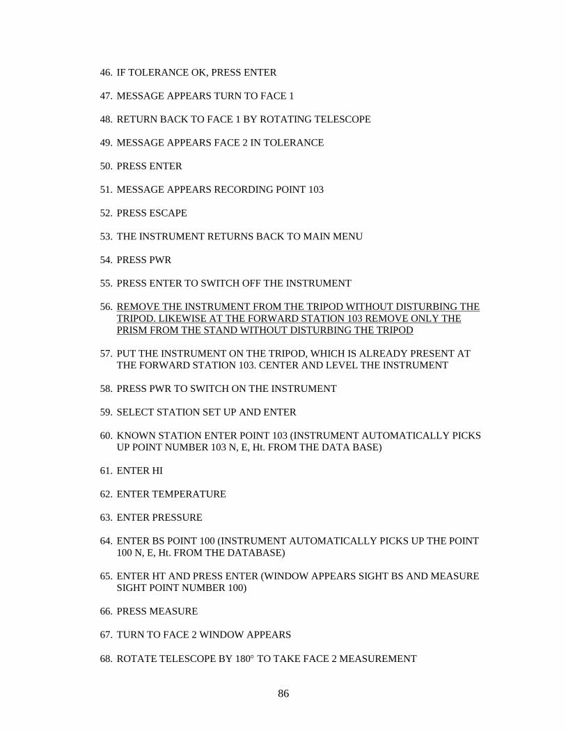
86
46. IF TOLERANCE OK, PRESS ENTER
47. MESSAGE APPEARS TURN TO FACE 1
48. RETURN BACK TO FACE 1 BY ROTATING TELESCOPE
49. MESSAGE APPEARS FACE 2 IN TOLERANCE
50. PRESS ENTER
51. MESSAGE APPEARS RECORDING POINT 103
52. PRESS ESCAPE
53. THE INSTRUMENT RETURNS BACK TO MAIN MENU
54. PRESS PWR
55. PRESS ENTER TO SWITCH OFF THE INSTRUMENT
56. REMOVE THE INSTRUMENT FROM THE TRIPOD WITHOUT DISTURBING THE
TRIPOD. LIKEWISE AT THE FORWARD STATION 103 REMOVE ONLY THE
PRISM FROM THE STAND WITHOUT DISTURBING THE TRIPOD
57. PUT THE INSTRUMENT ON THE TRIPOD, WHICH IS ALREADY PRESENT AT
THE FORWARD STATION 103. CENTER AND LEVEL THE INSTRUMENT
58. PRESS PWR TO SWITCH ON THE INSTRUMENT
59. SELECT STATION SET UP AND ENTER
60. KNOWN STATION ENTER POINT 103 (INSTRUMENT AUTOMATICALLY PICKS
UP POINT NUMBER 103 N, E, Ht. FROM THE DATA BASE)
61. ENTER HI
62. ENTER TEMPERATURE
63. ENTER PRESSURE
64. ENTER BS POINT 100 (INSTRUMENT AUTOMATICALLY PICKS UP THE POINT
100 N, E, Ht. FROM THE DATABASE)
65. ENTER HT AND PRESS ENTER (WINDOW APPEARS SIGHT BS AND MEASURE
SIGHT POINT NUMBER 100)
66. PRESS MEASURE
67. TURN TO FACE 2 WINDOW APPEARS
68. ROTATE TELESCOPE BY 180 TO TAKE FACE 2 MEASUREMENT

87
69. SIGHT TARGET POINT NUMBER 100
70. PRESS MEASURE
71. MESSAGE APPEARS TOLERANCE OK OR TOLERANCE OUT
72. IF OUT OF TOLERANCE, REDO FACE 1 AND FACE 2 MEASUREMENT
73. IF TOLERANCE OK, PRESS ENTER
74. MESSAGE APPEARS TURN TO FACE 1
75. RETURN BACK TO FACE 1 BY ROTATING TELESCOPE
76. PRESS OK IF BS FACE I AND FACE 2 MEAN IS OK
77. MESSAGE RECORDING STATION APPEARS AND DISPLAY RETURNS TO
MAIN MENU
78. SELECT COLLECTION AND PRESS ENTER
79. SIDE SHOT WINDOW APPEARS
80. POINT NUMBER 104 (READY FOR MEASUREMENT)
81. SIGHT FORWARD STATION SAY 104 ST3
82. ENTER HT PRESS ENTER
83. ENTER STATION CODE ST3
84. SIGHT POINT NUMBER 104
85. PRESS MEASURE
86. ROTATE TELESCOPE BY 180 TO TAKE FACE 2 MEASUREMENT
87. PRESS MEASURE
88. MESSAGE APPEARS TOLERANCE OK OR TOLERANCE OUT
89. IF OUT OF TOLERANCE, REDO FACE 1 AND FACE 2 MEASUREMENT
90. IF TOLERANCE OK, PRESS ENTER
91. MESSAGE APPEARS TURN TO FACE 1
92. RETURN BACK TO FACE 1 BY ROTATING TELESCOPE AND TOTAL STATION
93. MESSAGE APPEARS FACE 2 IN TOLERANCE
94. PRESS ENTER
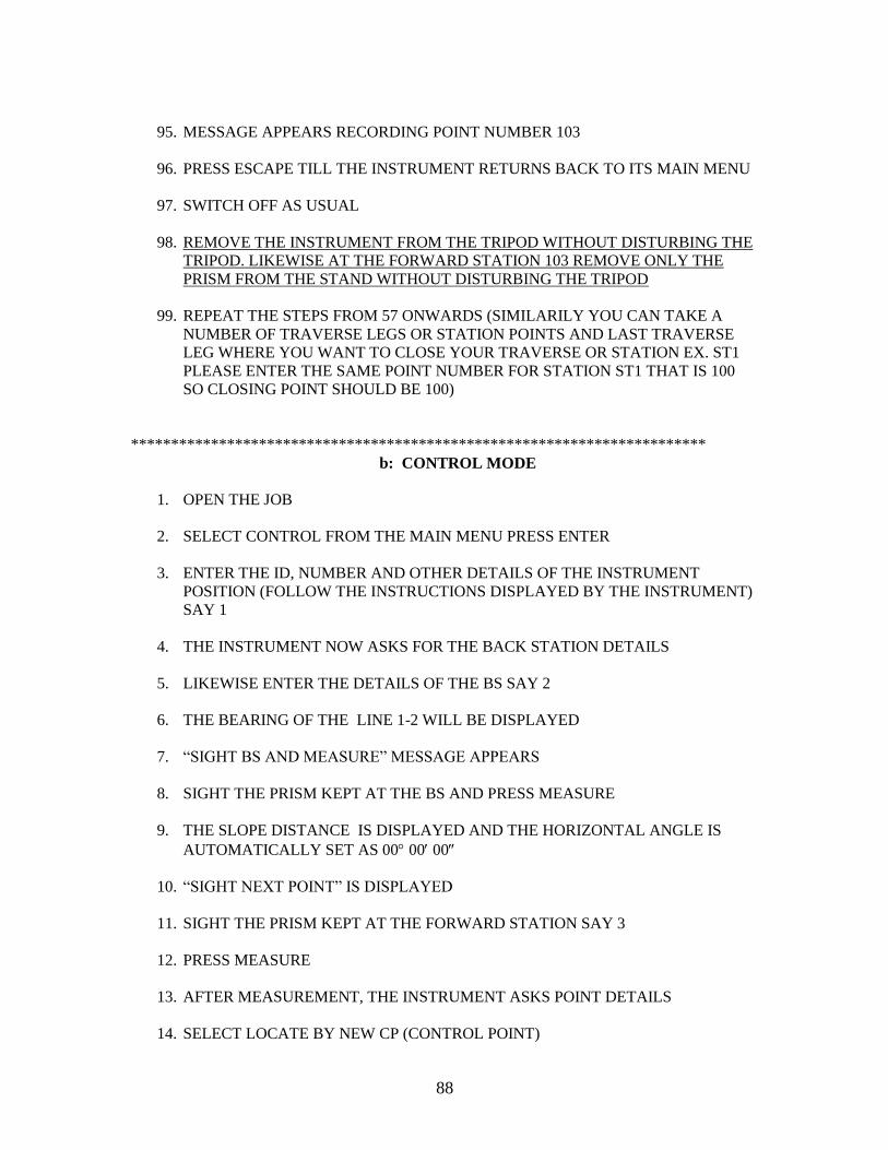
88
95. MESSAGE APPEARS RECORDING POINT NUMBER 103
96. PRESS ESCAPE TILL THE INSTRUMENT RETURNS BACK TO ITS MAIN MENU
97. SWITCH OFF AS USUAL
98. REMOVE THE INSTRUMENT FROM THE TRIPOD WITHOUT DISTURBING THE
TRIPOD. LIKEWISE AT THE FORWARD STATION 103 REMOVE ONLY THE
PRISM FROM THE STAND WITHOUT DISTURBING THE TRIPOD
99. REPEAT THE STEPS FROM 57 ONWARDS (SIMILARILY YOU CAN TAKE A
NUMBER OF TRAVERSE LEGS OR STATION POINTS AND LAST TRAVERSE
LEG WHERE YOU WANT TO CLOSE YOUR TRAVERSE OR STATION EX. ST1
PLEASE ENTER THE SAME POINT NUMBER FOR STATION ST1 THAT IS 100
SO CLOSING POINT SHOULD BE 100)
************************************************************************
b: CONTROL MODE
1. OPEN THE JOB
2. SELECT CONTROL FROM THE MAIN MENU PRESS ENTER
3. ENTER THE ID, NUMBER AND OTHER DETAILS OF THE INSTRUMENT
POSITION (FOLLOW THE INSTRUCTIONS DISPLAYED BY THE INSTRUMENT)
SAY 1
4. THE INSTRUMENT NOW ASKS FOR THE BACK STATION DETAILS
5. LIKEWISE ENTER THE DETAILS OF THE BS SAY 2
6. THE BEARING OF THE LINE 1-2 WILL BE DISPLAYED
7. ―SIGHT BS AND MEASURE‖ MESSAGE APPEARS
8. SIGHT THE PRISM KEPT AT THE BS AND PRESS MEASURE
9. THE SLOPE DISTANCE IS DISPLAYED AND THE HORIZONTAL ANGLE IS
AUTOMATICALLY SET AS 00 00 00
10. ―SIGHT NEXT POINT‖ IS DISPLAYED
11. SIGHT THE PRISM KEPT AT THE FORWARD STATION SAY 3
12. PRESS MEASURE
13. AFTER MEASUREMENT, THE INSTRUMENT ASKS POINT DETAILS
14. SELECT LOCATE BY NEW CP (CONTROL POINT)
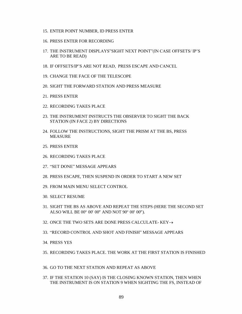
89
15. ENTER POINT NUMBER, ID PRESS ENTER
16. PRESS ENTER FOR RECORDING
17. THE INSTRUMENT DISPLAYS‖SIGHT NEXT POINT‖(IN CASE OFFSETS/ IP‘S
ARE TO BE READ)
18. IF OFFSETS/IP‘S ARE NOT READ, PRESS ESCAPE AND CANCEL
19. CHANGE THE FACE OF THE TELESCOPE
20. SIGHT THE FORWARD STATION AND PRESS MEASURE
21. PRESS ENTER
22. RECORDING TAKES PLACE
23. THE INSTRUMENT INSTRUCTS THE OBSERVER TO SIGHT THE BACK
STATION (IN FACE 2) BY DIRECTIONS
24. FOLLOW THE INSTRUCTIONS, SIGHT THE PRISM AT THE BS, PRESS
MEASURE
25. PRESS ENTER
26. RECORDING TAKES PLACE
27. ―SET DONE‖ MESSAGE APPEARS
28. PRESS ESCAPE, THEN SUSPEND IN ORDER TO START A NEW SET
29. FROM MAIN MENU SELECT CONTROL
30. SELECT RESUME
31. SIGHT THE BS AS ABOVE AND REPEAT THE STEPS (HERE THE SECOND SET
ALSO WILL BE 00 00 00 AND NOT 90 00 00).
32. ONCE THE TWO SETS ARE DONE PRESS CALCULATE- KEY
33. ―RECORD CONTROL AND SHOT AND FINISH‖ MESSAGE APPEARS
34. PRESS YES
35. RECORDING TAKES PLACE. THE WORK AT THE FIRST STATION IS FINISHED
36. GO TO THE NEXT STATION AND REPEAT AS ABOVE
37. IF THE STATION 10 (SAY) IS THE CLOSING KNOWN STATION, THEN WHEN
THE INSTRUMENT IS ON STATION 9 WHEN SIGHTING THE FS, INSTEAD OF

90
SELECTING ―LOCATE BY SURVEY NEW CP‖ SELECT INPUT, AND THEN
INPUT THE KNOWN COORDINATES OF THE STATION 10
38. WHEN ON STATION 10, WHEN SIGHTING THE FORWARD STATION, AGAIN
CHOOSE INPUT AND FEED THE COORDINATES OF THE FORWARD STATION
FOR BEARING PURPOSE.
K: TRAVERSE ADJUSTMENT IN THE INSTRUMENT
1. JOB SHOULD BE OPEN
2. FROM MAIN MENU SELECT TRAVERSE ADJUSTMENT
3. PRESS ENTER
4. A GRAPH WILL APPEAR WITH ALL THE STATION POINTS
5. PRESS START KEY
6. ENTER STARTING AND CLOSING POINTS
7. PRESS CONTINUOUS
8. THE DOTTED LINES IN THE GRAPH WILL BECOME SOLID LINE
9. PRESS COMPUTE
10. ACCURACY OF THE LINE WILL APPEAR ALONG WITH ADJUSTMENT
METHODS i.e.
a. BOWDITCH RULE
b. TRANSIT RULE
c. COMPASS RULE
11. ELECT ―a‖
12. PRESS ENTER
13. MESSAGE ―ADJUSTING COORDINATES WILL APPEAR‖
14. MESSAGE ―ADJUSTMENT COMPLETED WILL APPEAR‖
15. PRESS ENTER
B: INSTALLATION OF THE SOFTWARE

91
A: HOW TO INSTALL AP-800 (SYSTEM SOFTWARE) IN DTM 851
1. INSERT AP-800 VERSION 2.32 PROGRAM CARD IN DTM 851 CARD SLOT
2. PRESS PWR KEY
3. MESSAGE APPEARS ―TILT TELESCOPE‖
4. TILT THE TELESCOPE. MESSAGE APPEARS AP-800 VERSION 2.32
INSTALLING APPLICATIONS.
5. PRESS ENTER TO START
6. MESSAGE APPEARS ―INITIALISING…………..‖ (WRITING PROGRESSIVE BAR
APPEARS)
7. FINISHED MESSAGE APPEARS
8. REMOVE CARD AND PRESS ANY KEY
B: HOW TO FORMAT SRAM DATA CARD
THIS PROCEDURE CAN BE DONE UNDER THE FOLLOWING CONDITIONS:
a. IF YOU ARE USING NEW DATA CARD
b. IF YOU FACE ANY PROBLEM IN DATA
c. IF YOU ARE STARTING YOUR PROJECT AFTER TWO TO THREE
MONTHS
d. IF YOUR DATA CARD IS FULL. (NOTE: MAKE SURE THAT YOUR DATA
HAS BEEN DOWNLOADED INTO YOUR PC)}
1. PRESS PWR KEY
2. TILT TELESCOPE
3. MAIN MENU APPEAR
4. SELECT SYSTEM AND PRESS ENTER
5. SELECT FORMAT CARD AND ENTER
6. WARNING MESSAGE WILL APPEAR (AP-800 WILL REBOOT)
7. SELECT OK AND PRESS ENTER
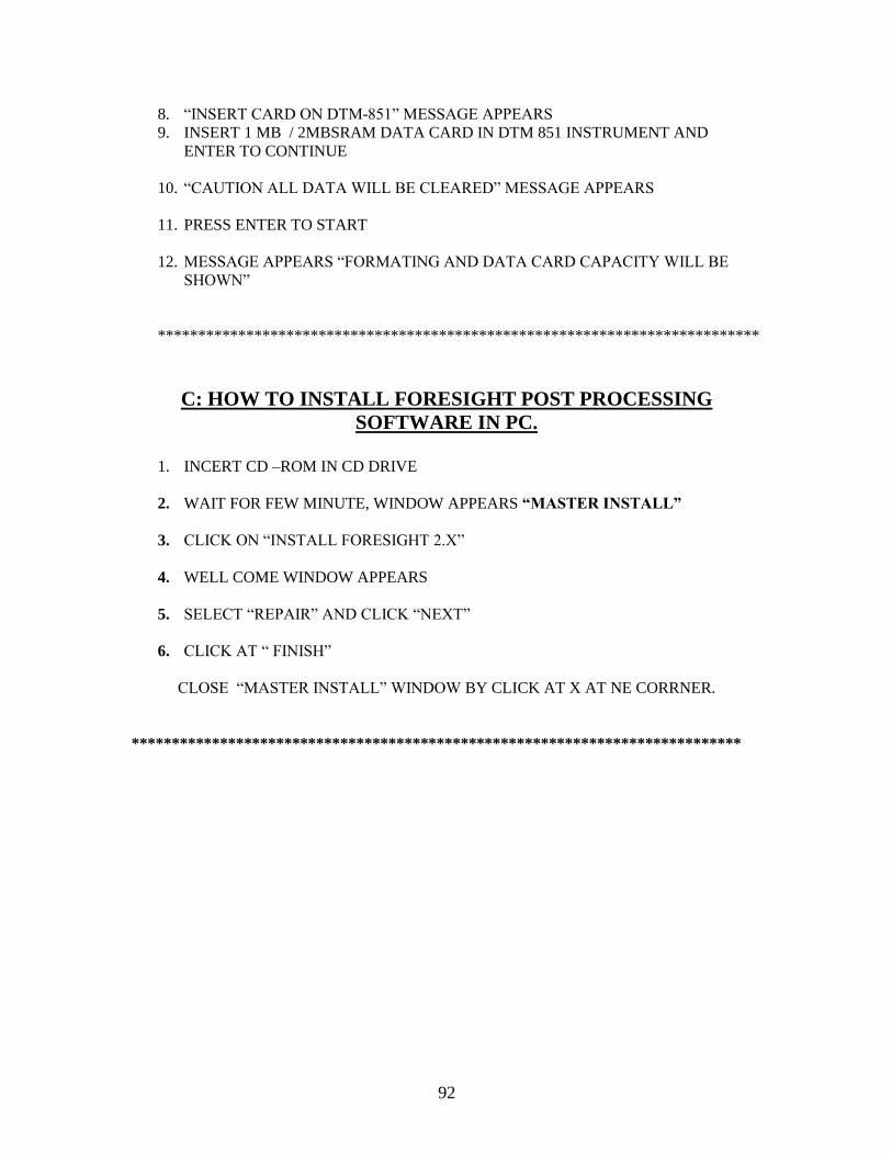
92
8. ―INSERT CARD ON DTM-851‖ MESSAGE APPEARS
9. INSERT 1 MB / 2MBSRAM DATA CARD IN DTM 851 INSTRUMENT AND
ENTER TO CONTINUE
10. ―CAUTION ALL DATA WILL BE CLEARED‖ MESSAGE APPEARS
11. PRESS ENTER TO START
12. MESSAGE APPEARS ―FORMATING AND DATA CARD CAPACITY WILL BE
SHOWN‖
***************************************************************************
C: HOW TO INSTALL FORESIGHT POST PROCESSING
SOFTWARE IN PC.
1. INCERT CD –ROM IN CD DRIVE
2. WAIT FOR FEW MINUTE, WINDOW APPEARS ―MASTER INSTALL‖
3. CLICK ON ―INSTALL FORESIGHT 2.X‖
4. WELL COME WINDOW APPEARS
5. SELECT ―REPAIR‖ AND CLICK ―NEXT‖
6. CLICK AT ― FINISH‖
CLOSE ―MASTER INSTALL‖ WINDOW BY CLICK AT X AT NE CORRNER.
****************************************************************************

93
D: HOW TO INSTALL CARD READER DRIVER (ACCENT)
1. INSERT I.44 DISC INTO A FLOPPY DISC DRIVE
2. CLICK AT MY COMPUTER
3. MY COMPUTER WINDOW WILL APPEAR
4. DOUBLE CLICK ON 3.5 FLOPPY (A:) DISK
5. A DRIVE WINDOW WILL APPEAR
6. DOUBLE CLICK ON WIN 2K IN PC
7. WIN 2K WINDOW APPEARS
8. DOUBLE CLICK ON SETUP
9. ―ADTRON ACCENT SETUP‖ WINDOW APPEARS
10. CLICK INSTALL DRIVE, (IF YOU ARE INSTALLING FOR THE
FIRST TIME) OR UPGRADE DRIVES
11. CONFIGURE DRIVE WINDOW APPEARS
12. PRESS OK
13. ―ADTRON ACCENT SETUP‖ WINDOW APPEARS AGAIN
14. CLICK OK
15. MESSAGE APPEARS ―REBOOT REQUIRED‖
16. CLICK YES AND PRESS ENTER
17. YOUR COMPUTER STARTS REBOOTING
18. RETURN TO START MENU (YOUR ACCENT DRIVER IS
INSTALLED IN PC.)
19. IF YOU WANT TO CHECK CLICK ON MY COMPUTER YOU WILL
SEE REMOVABLE DISK (G) IS LOADED.

94
C: DOWNLOADING
A: HOW TO DOWNLOAD DATA FROM CARD READER
1. CONNECT THE ACCENT DRIVER TO LPT PORT, PRINTER PORT AND ALSO
ONE END TO POWER SUPPLY. MAKE SURE THAT RED LIGHT SHOULD
GLOW BEFORE YOU SWITCH ON THE PC
2. SWITCH ON THE COMPUTER. CREATE NEW FOLDER ON YOUR HARD DISC
3. CLICK AT MY COMPUTER
4. INSERT DATA MEMORY CARD (SRAM CARD) IN CARD READER
5. DOUBLE CLICK ON REMOVABLE DISK (G:)
6. ALL DATA WILL APPEAR ON THE WINDOW
7. CLICK AT EDIT
8. CLICK AT SELECT ALL (ALL DATA ARE SELECTED)
9. CLICK AT EDIT
10. CLICK AT COPY
11. CLICK AT MY COMPUTER
12. DOUBLE CLICK AT C: (WHERE YOU HAVE MADE A FOLDER OR DIRECTORY)
13. DOUBLE CLICK ON YOUR DIRECTORY/FOLDER
14. CLICK AT EDIT AND PASTE
15. ALL THE DATE IS COPIED FROM CARD READER

95
B: HOW TO DOWNLOAD DATA FROM INSTRUMENT TO
COMPUTER
1. CLICK AT START
2. ‖ PROGRAMME
3. ‖ FORESIGHT FOR NIKON
4. WEL COME WINDOW APPEARS
a. CREATE A NEW PROJECT
b. OPEN AN EXISTING PROJECT
c. OPEN THE LAST PROJECT YOU ARE WORKING ON
d.OPEN A SAMPLE PROJECT
5. CLICK AT CREATE NEW PROJECT
6. DATA SOURCE WINDOW WILL APPEAR
7. SELECT TRANSFER FROM NIKON INSTRUMENT
8. CLICK AT NEXT
9. TRANSFER FROM NIKON INSTRUMENT WINDOW APPEARS
10. SELECT DATA SOURCE: -AS NIKON AP 800 TOTAL STATION
11. SELECT:
COMPORT: COM.1
BAUD RATE: 9600
PARITY: NONE
DATA LENGTH: 8 BITS
STOPE BITS: 1
12. CLICK AT BROWSE
13. ENTER THE NAME OF RAW FILE / PATH OF THE FILE
14. CLICK AT SETTINGS (METER, ENZ, AZIMUTH FROM NORTH, DEGREE, ECT.)
15. CLICK AT OK
16. THE PC. IS READY TO RECEIVE THE DATA FROM INSTRUMENT.
AT TOTAL STATION (INSTRUMENT) OPEN YOUR JOB FILE WHICH HAS TO BE
DOWN LOADED INTO PC
17. PRESS PWR KEY
18. TILT TELSCOPE
19. MAIN MANU APPEARS

96
20. SELECT JOB MANAGER AND PRESS ENTER
21. SELECT YOUR JOB AND PRESS ENTER (JOB OPENING WIDOW APPEARS AND
RETURNS TO MAIN MENU)
22. AT MAIN MENU SELECT COMMUNICATION
23. SELECT DOWN LOAD AND PRESS ENTER
24. DOWN LOAD OPTIONS
1.DESTINATION: 1
2. DATA FORMAT: NIKON
3. TYPE OF DATA: RAW DATA
4. TIME STAMP: NONE
25. PRESS ENTER
1. PORT: COM.1
2. BAUD RATE: 9600
3. PARITY: NONE
4. DATA LENGTH: 8 BITS
5. STOP BITS: 1 AND PRESS ENTER
26.AT COMPUTER CLICK AT OK
26. AT TOTAL STATION (INSTRUMENT) PRESS ENTER
27. DATA TRANSFER IS COMPLETED AND MESSAGE APPEARS ―FILE
TRANSFERED SUCCSEFULLY‖
29.PRESS OK
30. DUPLICATE NUMBERING WINDOW APPEARS
31. RENUMBERING POINTS WILL APPEAR (RENUMBERING THE DUPLICATE
POINTS)
32. PRESS OK
33. FORESIGHT 2.0 WINDOW APPEARS
34. PRESS YES (YOU CAN SEE THE DUPLICATE NUMBERS LIST)
35. CLOSE THE WINDOW BY PRESSING AT X
36. CLICK AT NEXT
37. CLICK AT NEXT
e. CLICK AT FINISH (YOU CAN SEE THE POINTS AND LABELS ON PC
SCREEN.)
\
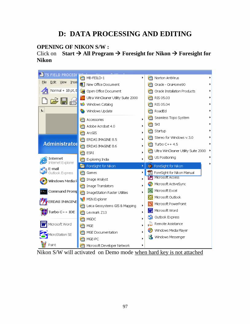
97
D: DATA PROCESSING AND EDITING
OPENING OF NIKON S/W :
Click on Start All Program Foresight for Nikon Foresight for
Nikon
Nikon S/W will activated on Demo mode when hard key is not attached
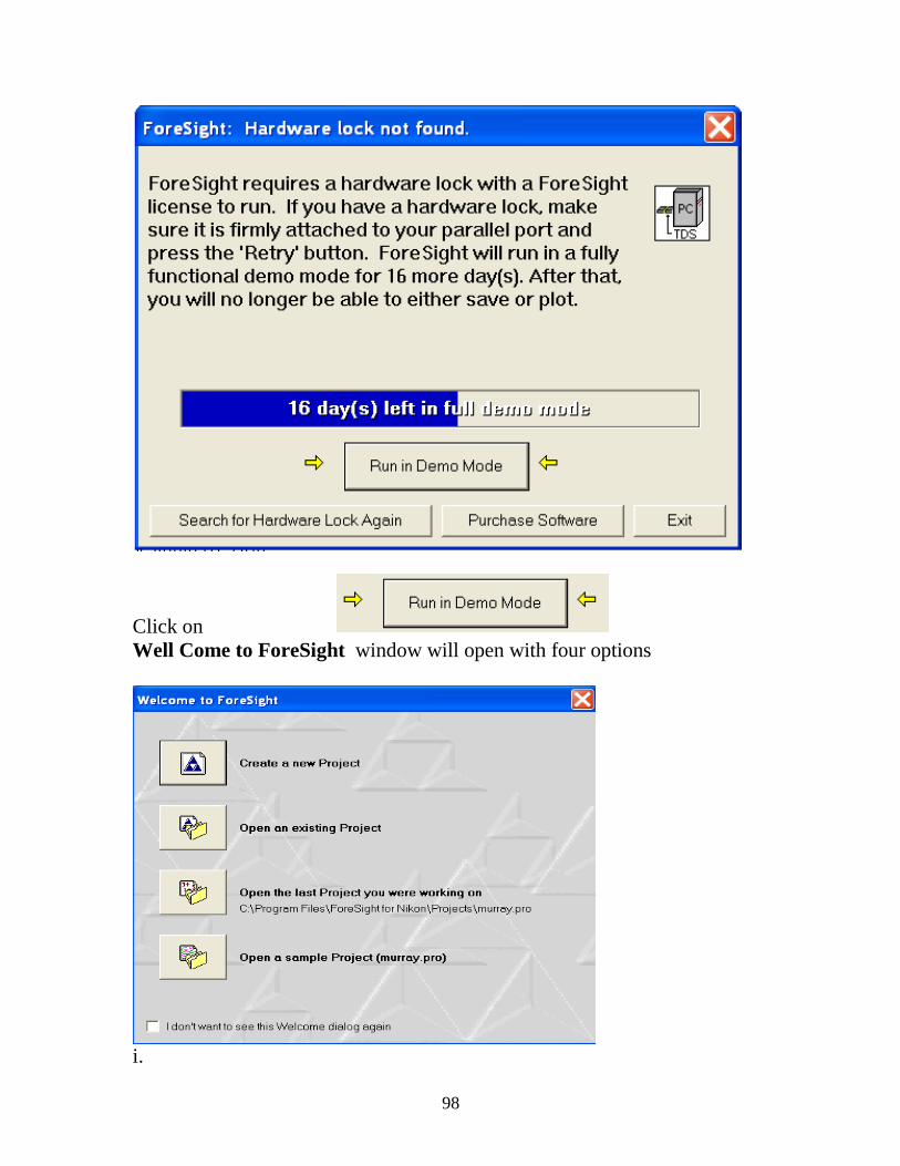
98
Click on
Well Come to ForeSight window will open with four options
i.
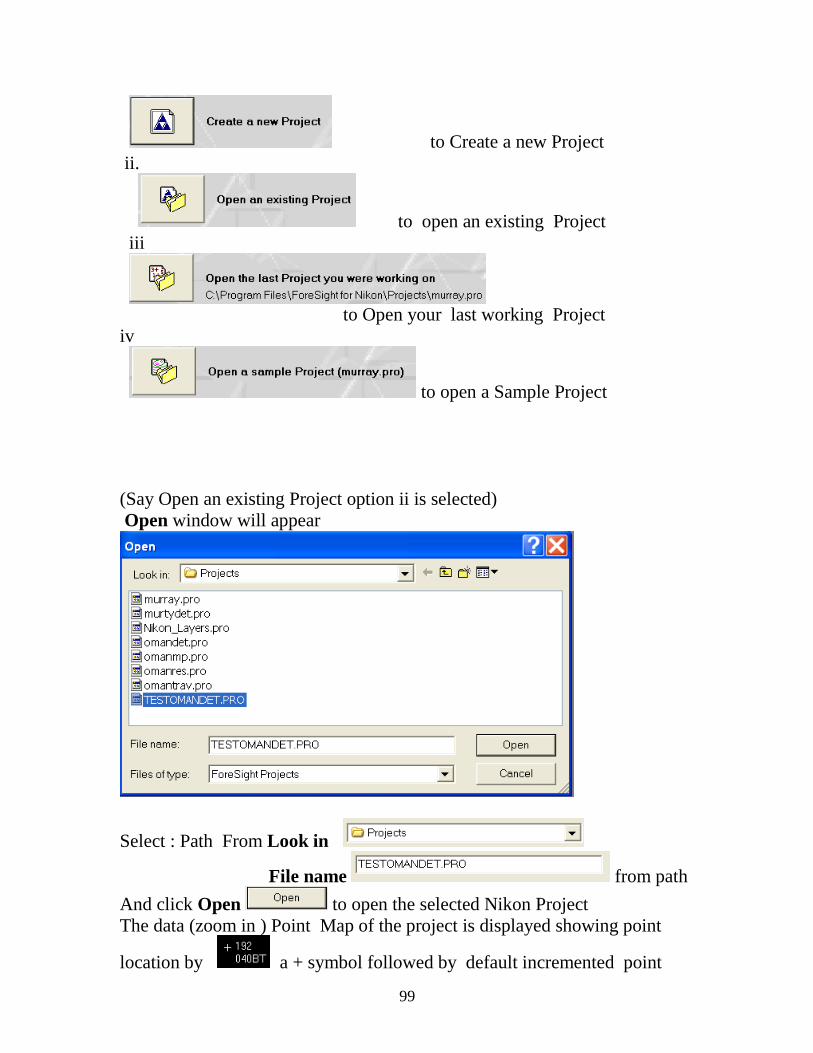
99
to Create a new Project
ii.
to open an existing Project
iii
to Open your last working Project
iv
to open a Sample Project
(Say Open an existing Project option ii is selected)
Open window will appear
Select : Path From Look in
File name from path
And click Open to open the selected Nikon Project
The data (zoom in ) Point Map of the project is displayed showing point
location by a + symbol followed by default incremented point
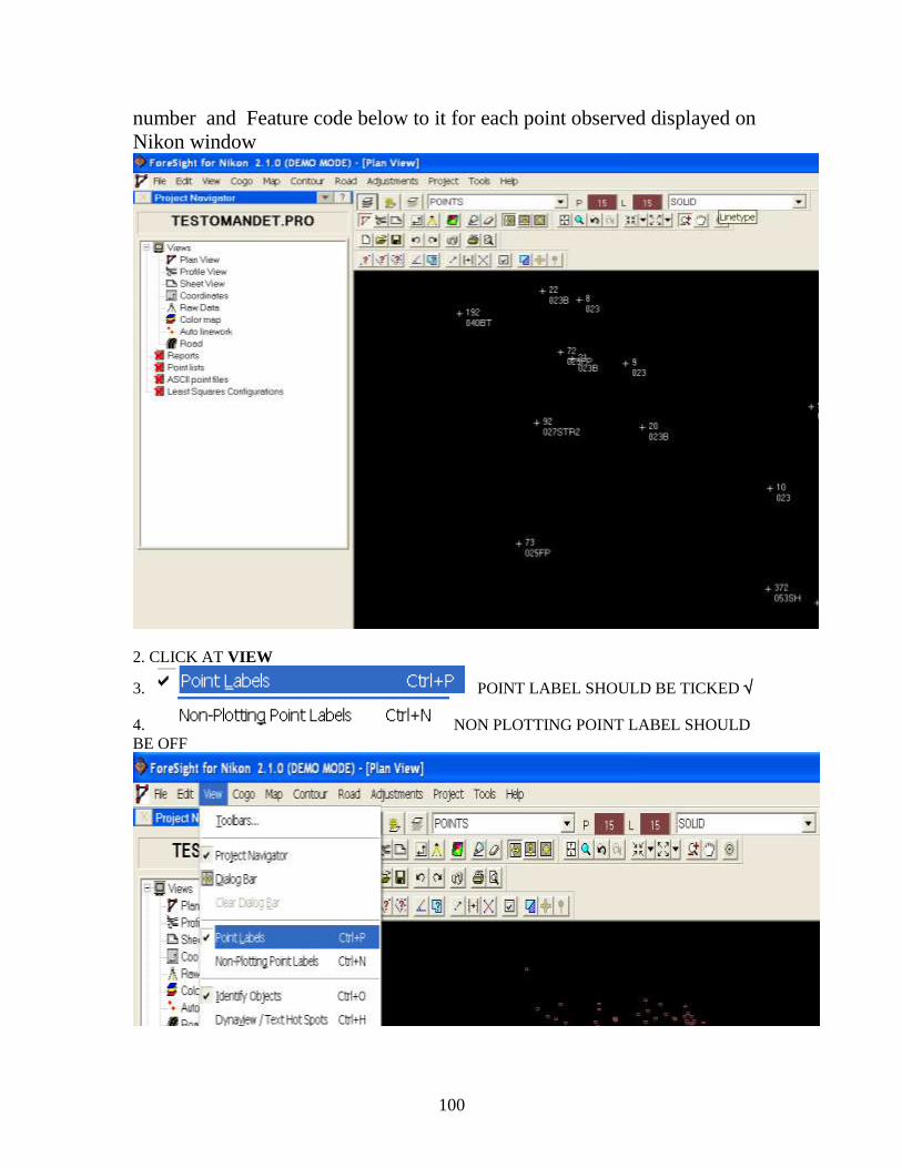
100
number and Feature code below to it for each point observed displayed on
Nikon window
2. CLICK AT VIEW
3. POINT LABEL SHOULD BE TICKED
4. NON PLOTTING POINT LABEL SHOULD
BE OFF
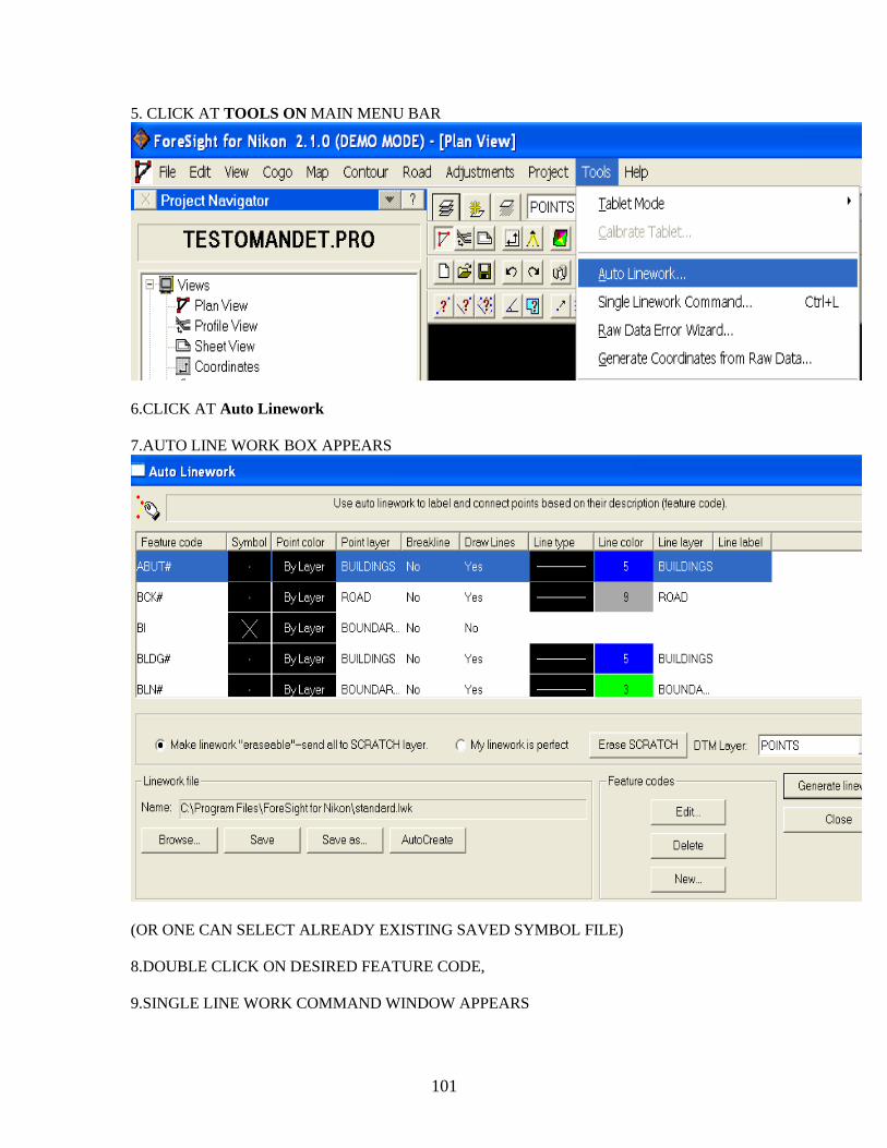
101
5. CLICK AT TOOLS ON MAIN MENU BAR
6.CLICK AT Auto Linework
7.AUTO LINE WORK BOX APPEARS
(OR ONE CAN SELECT ALREADY EXISTING SAVED SYMBOL FILE)
8.DOUBLE CLICK ON DESIRED FEATURE CODE,
9.SINGLE LINE WORK COMMAND WINDOW APPEARS
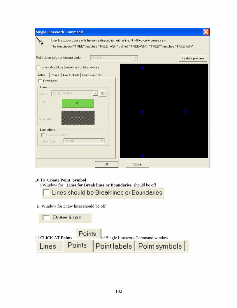
102
10 To Create Point Symbol
i.Window for Lines for Break lines or Boundaries should be off
ii. Window for Draw lines should be off
11.CLICK AT Points of Single Linework Command window
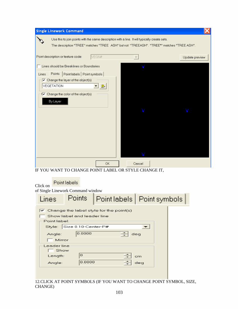
103
IF YOU WANT TO CHANGE POINT LABEL OR STYLE CHANGE IT,
Click on
of Single Linework Command window
12.CLICK AT POINT SYMBOLS (IF YOU WANT TO CHANGE POINT SYMBOL, SIZE,
CHANGE)
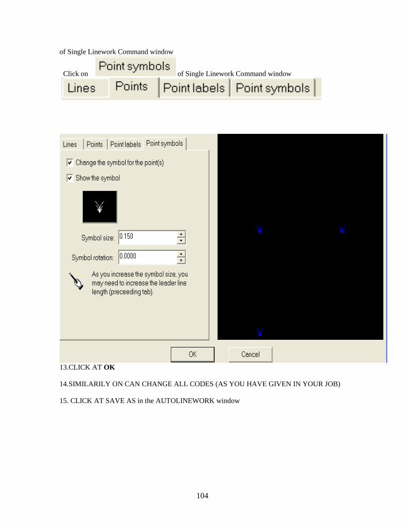
104
of Single Linework Command window
Click on of Single Linework Command window
13.CLICK AT OK
14.SIMILARILY ON CAN CHANGE ALL CODES (AS YOU HAVE GIVEN IN YOUR JOB)
15. CLICK AT SAVE AS in the AUTOLINEWORK window
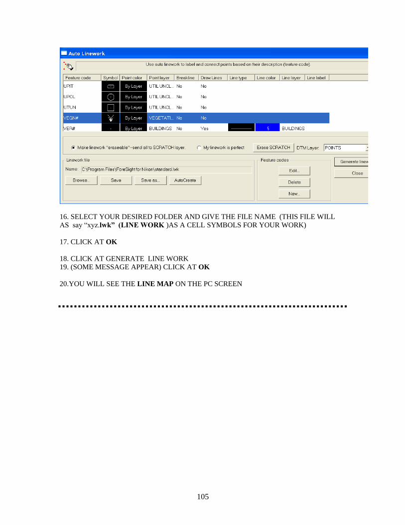
105
16. SELECT YOUR DESIRED FOLDER AND GIVE THE FILE NAME (THIS FILE WILL
AS say ―xyz.lwk‖ (LINE WORK )AS A CELL SYMBOLS FOR YOUR WORK)
17. CLICK AT OK
18. CLICK AT GENERATE LINE WORK
19. (SOME MESSAGE APPEAR) CLICK AT OK
20.YOU WILL SEE THE LINE MAP ON THE PC SCREEN
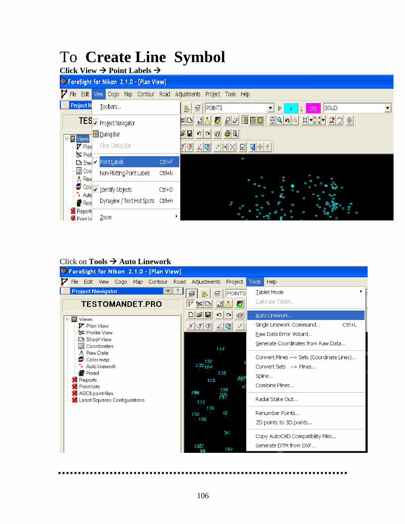
106
To Create Line Symbol Click View Point Labels
Click on Tools Auto Linework
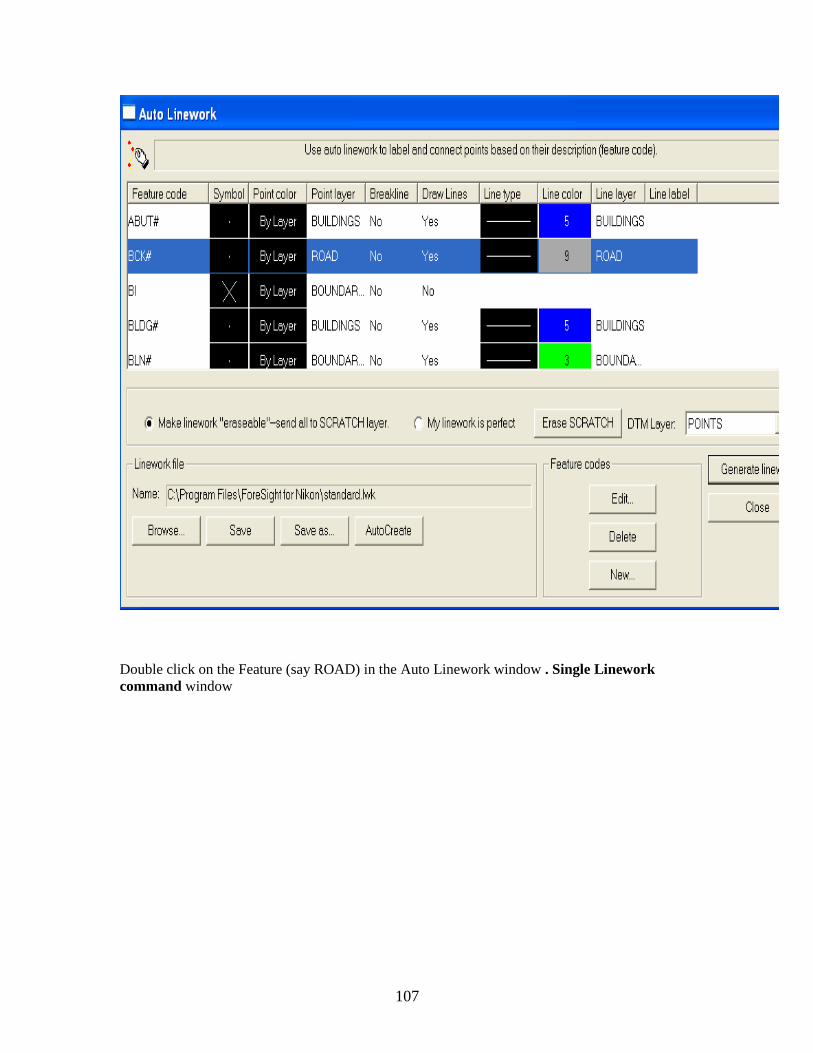
107
Double click on the Feature (say ROAD) in the Auto Linework window . Single Linework
command window
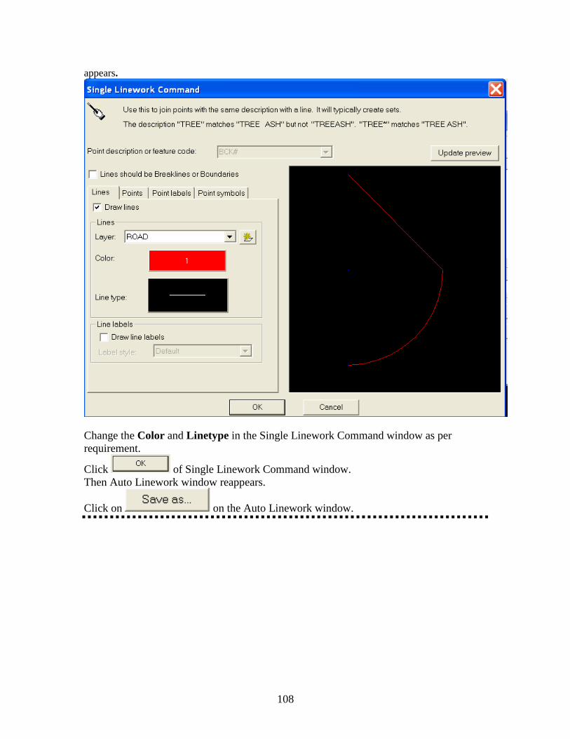
108
appears.
Change the Color and Linetype in the Single Linework Command window as per
requirement.
Click of Single Linework Command window.
Then Auto Linework window reappears.
Click on on the Auto Linework window.
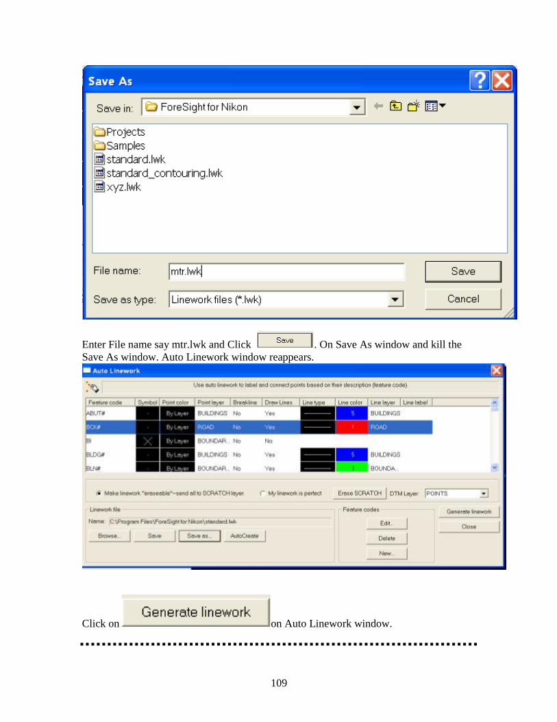
109
Enter File name say mtr.lwk and Click . On Save As window and kill the
Save As window. Auto Linework window reappears.
Click on on Auto Linework window.
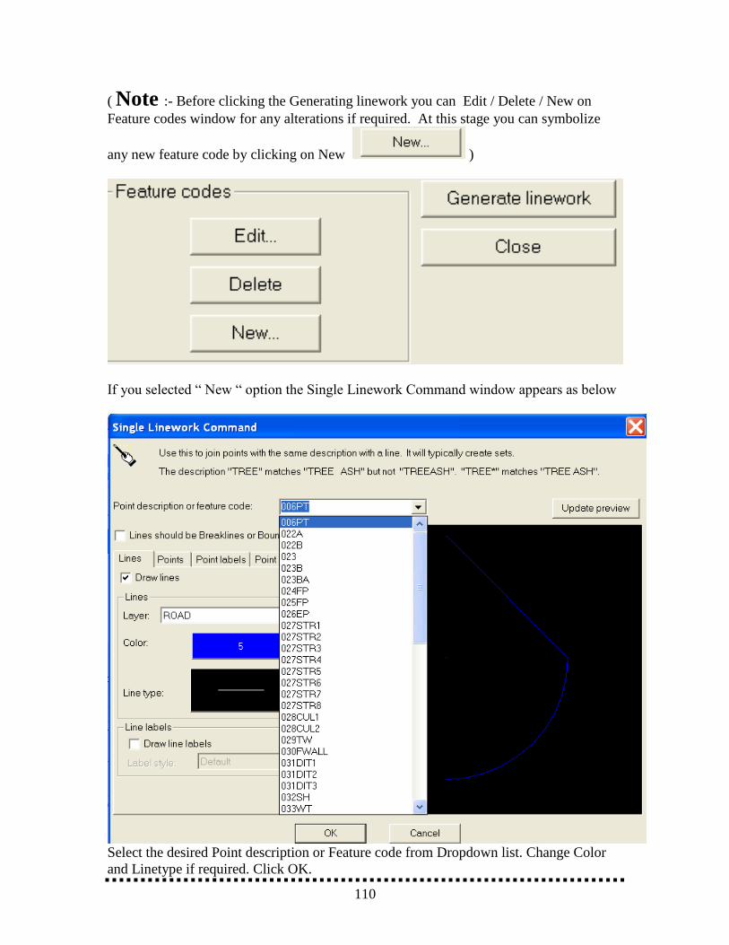
110
( Note :- Before clicking the Generating linework you can Edit / Delete / New on
Feature codes window for any alterations if required. At this stage you can symbolize
any new feature code by clicking on New )
If you selected ― New ― option the Single Linework Command window appears as below
Select the desired Point description or Feature code from Dropdown list. Change Color
and Linetype if required. Click OK.
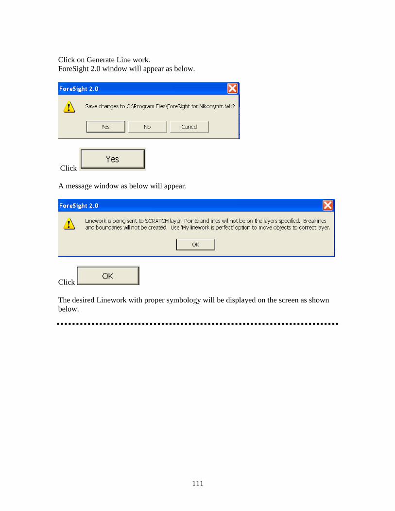
111
Click on Generate Line work.
ForeSight 2.0 window will appear as below.
Click
A message window as below will appear.
Click
The desired Linework with proper symbology will be displayed on the screen as shown
below.
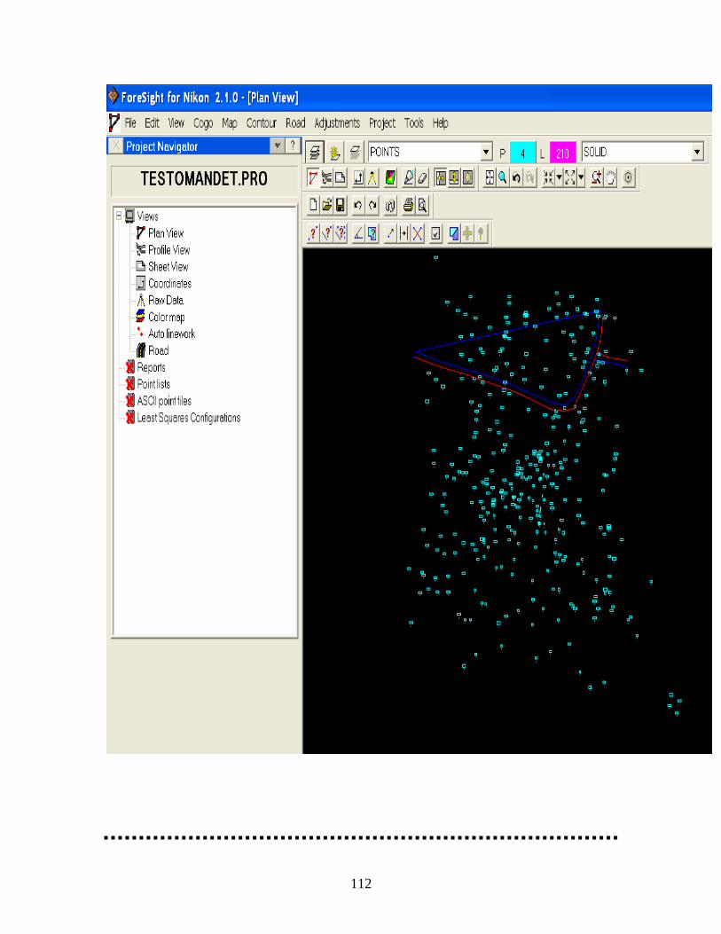
112
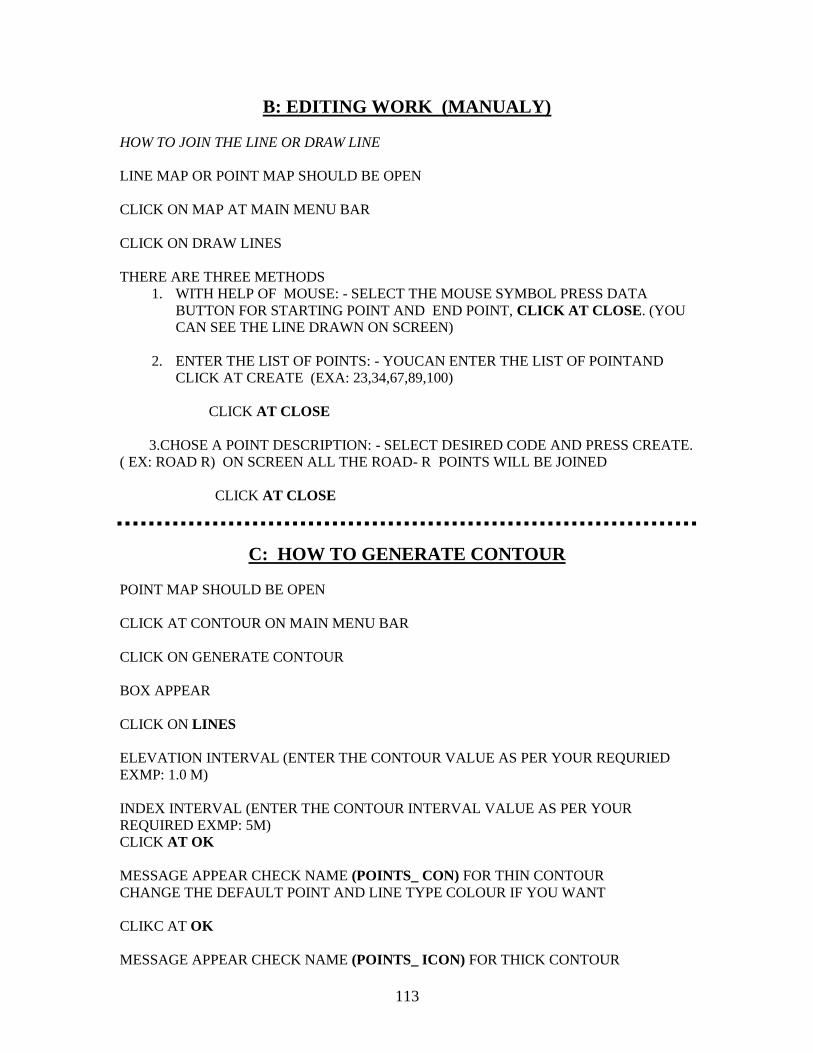
113
B: EDITING WORK (MANUALY)
HOW TO JOIN THE LINE OR DRAW LINE
LINE MAP OR POINT MAP SHOULD BE OPEN
CLICK ON MAP AT MAIN MENU BAR
CLICK ON DRAW LINES
THERE ARE THREE METHODS
1. WITH HELP OF MOUSE: - SELECT THE MOUSE SYMBOL PRESS DATA
BUTTON FOR STARTING POINT AND END POINT, CLICK AT CLOSE. (YOU
CAN SEE THE LINE DRAWN ON SCREEN)
2. ENTER THE LIST OF POINTS: - YOUCAN ENTER THE LIST OF POINTAND
CLICK AT CREATE (EXA: 23,34,67,89,100)
CLICK AT CLOSE
3.CHOSE A POINT DESCRIPTION: - SELECT DESIRED CODE AND PRESS CREATE.
( EX: ROAD R) ON SCREEN ALL THE ROAD- R POINTS WILL BE JOINED
CLICK AT CLOSE
C: HOW TO GENERATE CONTOUR
POINT MAP SHOULD BE OPEN
CLICK AT CONTOUR ON MAIN MENU BAR
CLICK ON GENERATE CONTOUR
BOX APPEAR
CLICK ON LINES
ELEVATION INTERVAL (ENTER THE CONTOUR VALUE AS PER YOUR REQURIED
EXMP: 1.0 M)
INDEX INTERVAL (ENTER THE CONTOUR INTERVAL VALUE AS PER YOUR
REQUIRED EXMP: 5M)
CLICK AT OK
MESSAGE APPEAR CHECK NAME (POINTS_ CON) FOR THIN CONTOUR
CHANGE THE DEFAULT POINT AND LINE TYPE COLOUR IF YOU WANT
CLIKC AT OK
MESSAGE APPEAR CHECK NAME (POINTS_ ICON) FOR THICK CONTOUR
114
CHANGE THE DEFAULT POINT AND LINE TYPE COLOUR IF YOU WANT
CLICK AT OK
CONTOUR (LINE) MAP ON THE SCREEN WILL DISPLAY
**************************************************************
D: HOW TO LABEL THE CONTOUR
(CONTOUR (LINE) MAP SHOULD BE OPEN)
CLICK AT CONTOUR ON MAINU BAR
CLICK ON LABEL CONTOUR
WE CAN LABEL THE CONTOUR BY TWO METHODS
1. HIGHTLIGHT THE MOUSE (CLICK ON THE MOUSE)
SELECT THE LOCATION ON THE CONTOUR LINE AND PRESS DATA
BUTTON ON THE CONTOUR LINE WHEREVER YOU WANT TO LABEL
2. HIGHLIGHT THE LABEL MULTIPLE CONTOUR LINES
LOCATION 1 E} PLACE THE CURSOR IN FIRST BOX WITH
N} FLICKERING BORDER APPEARS
PLACE THE CURSOR ON SCREEN (MAP) AND PRESS DATA BUTTON
LOCATION 2 1 E } PLACE THE CURSOR IN FIRST BOX WITH
N} FLICKERING BORDER APPEARS
PLACE THE CURSOR ON SCREEN (MAP) ON SOME OTHER END AND PRESS DATA
BUTTON
CLICK AT OK
YOU CAN SEE THE ALL THE CONTOURS ARE LABELED IN THAT DIRECTION
************************************************************************

115
E: HOW TO CHANGE THE UNITS
CLICK ON FILE AT MAIN MANU BAR
CLICK ON PROJECT OPTION
PROJECT OPTION WINDOW WILL APPEAR
CLICK ON UNITS
UNIT FOR SURVEY DATA: METERS
UNIT FOR PAGE LAYOUT: CENTIMETER
UNITS FOR ANGLE: DEGREES
AZIMUTH TYPE: NORTH AZIMUTH
CLICK ON APPLY
CLICK ON OK
F: HOW TO CHANGE THE PLOTING SCALE
CLICK ON FILE AT MAIN MANU BAR
CLICK ON PROJECT OPTION
CLICK ON PLAN
PLOT SCALE WINDOW APPEAR YOU CAN CHANGE THE SCALE (AS YOU DESIRE)
CLICK ON OK
G: HOW TO HAVE GRID LINE
CLICK ON FILE AT MAIN MANU BAR
CLICK ON PROJECT OPTION
CLICK ON PLAN
PLOT SCALE WINDOW APPEAR
√ TICK ON SHOW GRID
116
GRID COLOUR: SELECT YOUR DESIRED COLOUR
GRID INTERVAL: TYPE THE DESIRED GRID INTERVAL
GRID TYPE: HIGH LIGHT LINE
CLICK ON APPLY
CLICK ON OK
H: HOW TO PREPARE THE PLOT SHEET
CLICK ON FILE AT MAIN MENU BAR
CLICK ON PLOT WIZARD
PLOT WIZARD WINDOW APPEARS
PAPER SIZE: LETTER
CLICK ON SET UP PLOTTER/PAPER
PLOT SETUP WINDOW APPEAR
SIZE: LETTER
ORIENTATION MARGIN
√ CLICK ON PORTRAIT LEFT: 0.97 RIGHT: 1(YOU CAN CHANGE)
TOP: 1 BOT: 1
CLICK ON OK
SELECT THE STYLE OF THE SHEET (THREE OPTIONS ARE AVAILABLE)
1. SIMPLE (NOT TITLE BLOCK)
2. HORIZONTAL TITLE BLOCK
3. VERTICAL TITLE BLOCK
(SELECT ANYONE OF THE ABOVE OPTION)
CLICK ON NEXT
MESSAGE APPEAR CLICK OK
SELCTING TO THE AREA TO PLOT WINDOW APPEAR
SELECT THE CORNERS THAT BOUND LTHAT AREA THAT YOU ARE
PLOTTING

117
CORNER 1 AND DRAG THE MOUSE TO CORNER 2
YOU CAN SEE THE CO ORDINATES IN BOTH THE BOXES
CLICK ON NEXT
PLACING THE DYNAMIC VIEW WINDOW APPEAR
IF REQUIRED CHANGE THE CUSTOM SCALE (SAY 1M=1000M)
CLICK ON MOUSE SYMBOL AND PLACE A BOX
CLICK ON NEXT
ADDING NORTH ARROW AND SCALE BARS WINDOW APPEAR
SELECT THE TYPE OF NORTH ARROW AND HIGH LIGHT MOUSE SYMBOL AND
PLACE THE NORTH ARROW ON PROPER PLACE
AGAIN HIGHLIGHT MOUSE SYMBOL AND PLACE THE SCALE BAR ON PLOT SHEET
(PROPER PLACE)
CLICK ON NEXT
CLICK ON NEXT YOU CAN SEE THE PLOT SHEET ON SCREEN
SELECT THE ORIENTATION OF THE PAPER
YOU CAN SEE THE PREVIEW OF THE MAP ON CLICKING ON THE PREVIEW OF THE
MAP
IF PLOTTER IS ATTACHED WITH YOUR COMPUTER YOU CAN CLICK ON PLOT
CLICK ON FINISH
MESSAGE APPEARS CLICK ON YES
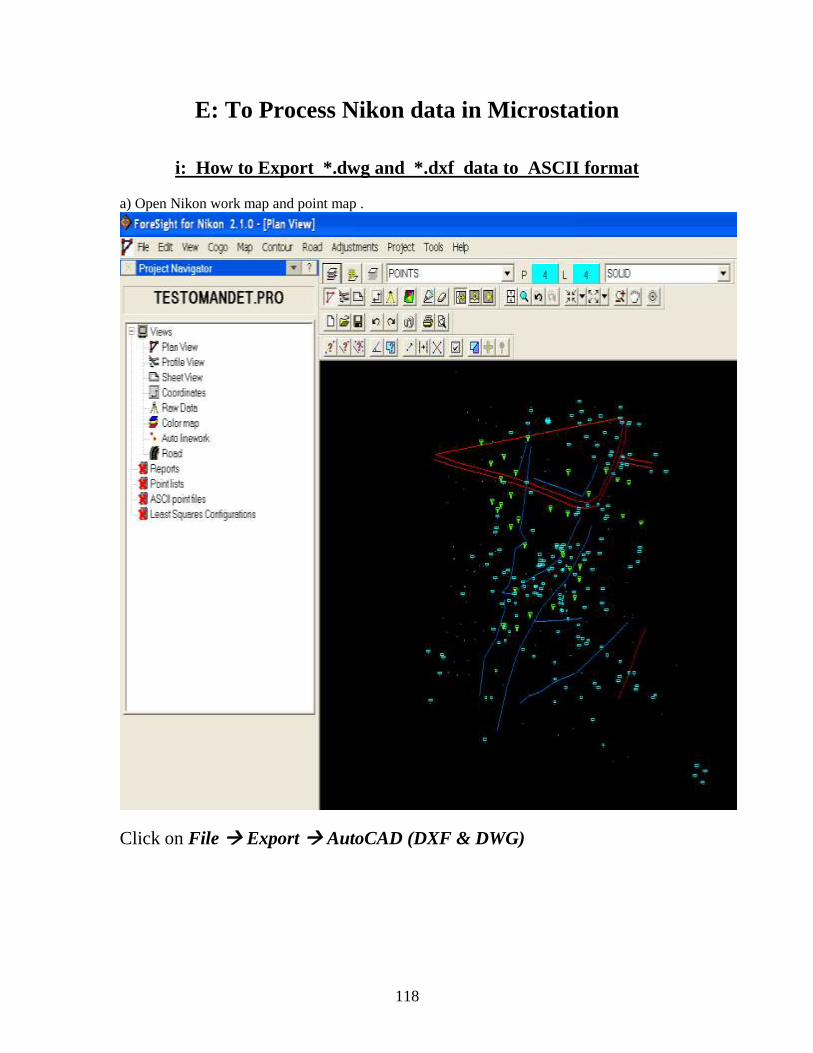
118
E: To Process Nikon data in Microstation
i: How to Export *.dwg and *.dxf data to ASCII format
a) Open Nikon work map and point map .
Click on File Export AutoCAD (DXF & DWG)
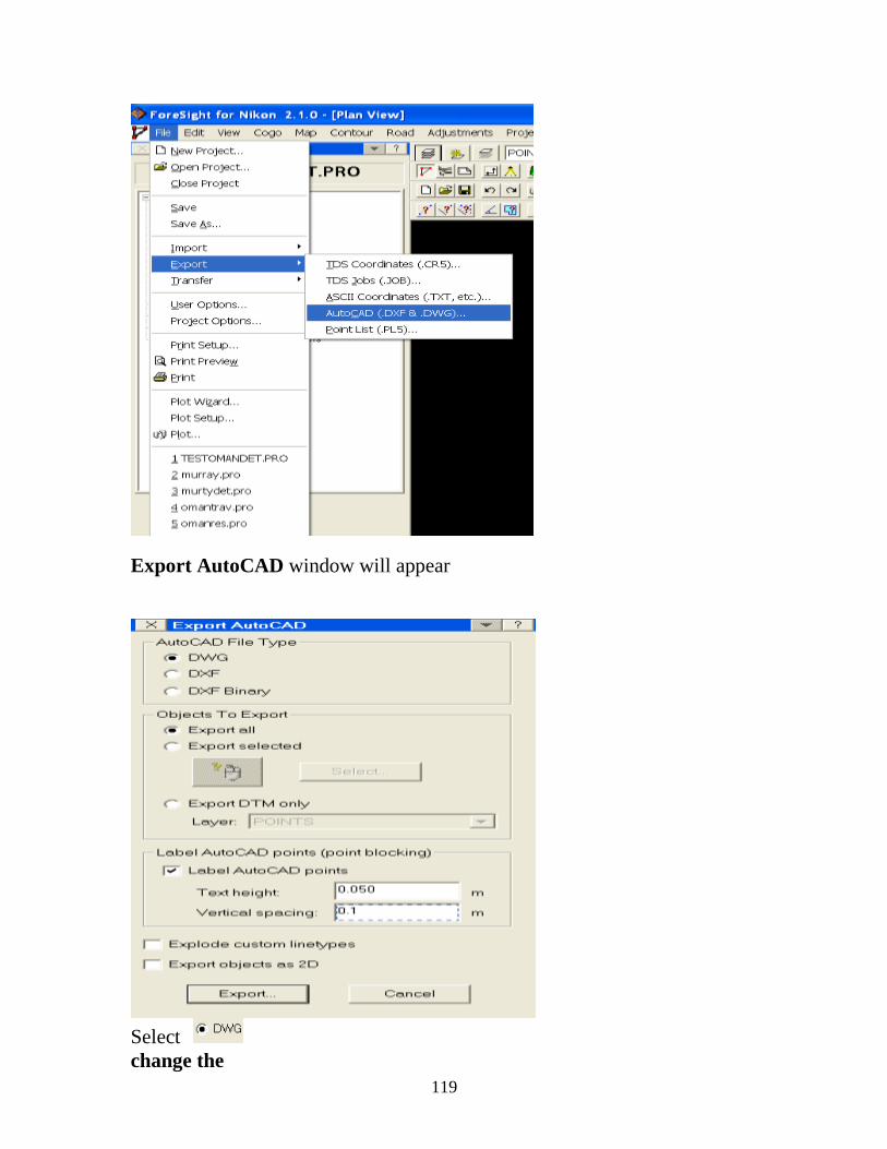
119
Export AutoCAD window will appear
Select
change the
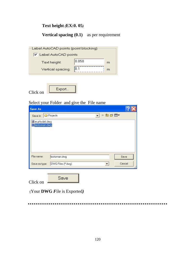
120
Text height (EX:0. 05)
Vertical spacing (0.1) as per requirement
Click on
Select your Folder and give the File name
Click on
(Your DWG File is Exported)
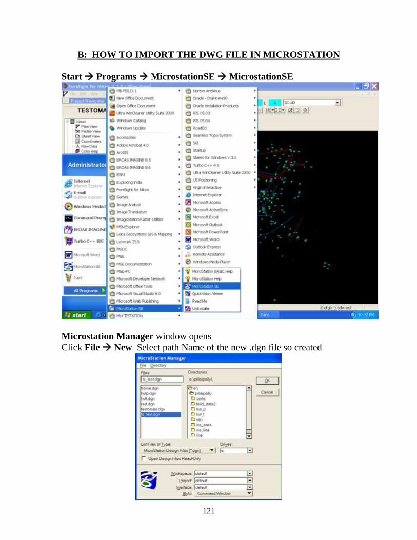
121
B: HOW TO IMPORT THE DWG FILE IN MICROSTATION
Start Programs MicrostationSE MicrostationSE
Microstation Manager window opens
Click File New Select path Name of the new .dgn file so created
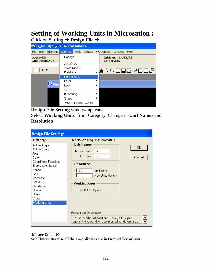
122
Setting of Working Units in Microsation : Click on Setting Design File
Design File Setting window appears
Select Working Units from Category Change in Unit Names and
Resolution
Master Unit=100 Sub Unit=1 Because all the Co-ordinates are in Ground Terms) ###
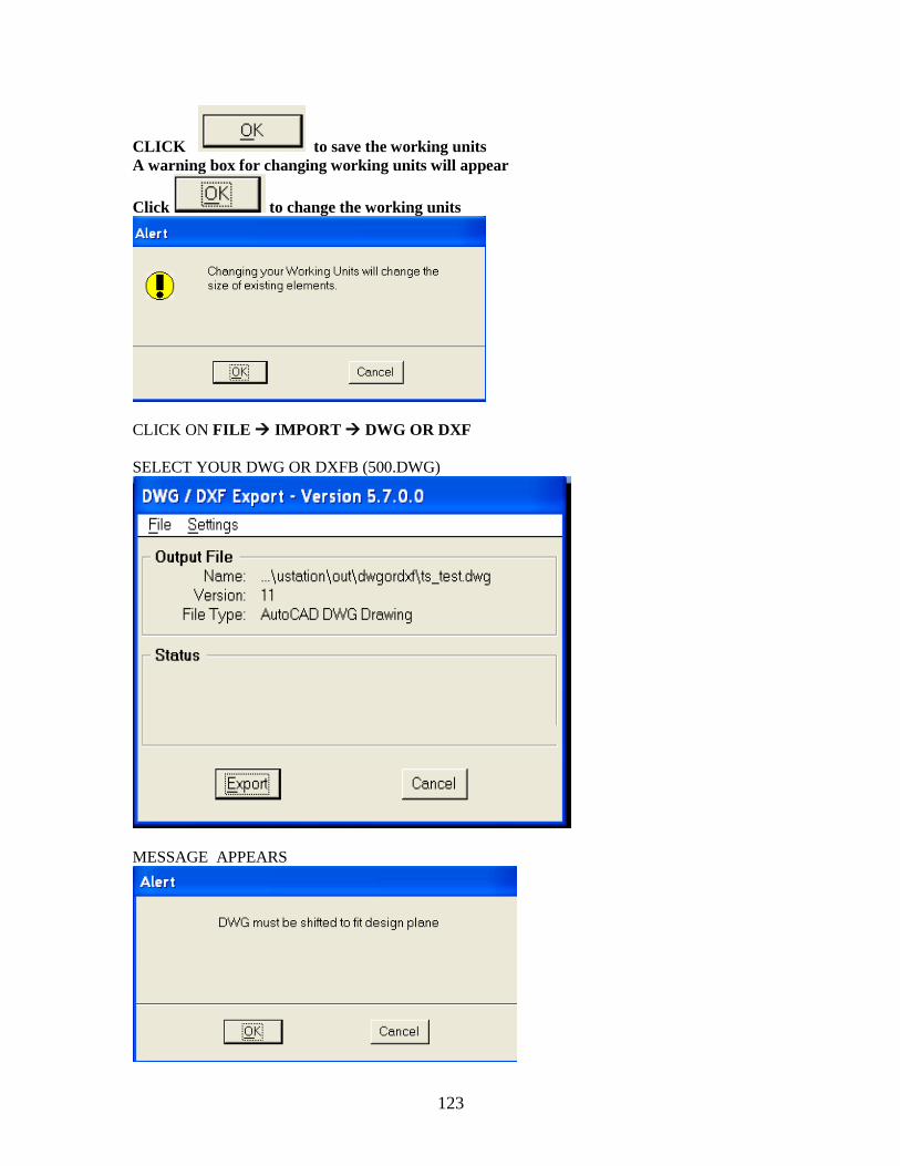
123
CLICK to save the working units
A warning box for changing working units will appear
Click to change the working units
CLICK ON FILE IMPORT DWG OR DXF
SELECT YOUR DWG OR DXFB (500.DWG)
MESSAGE APPEARS
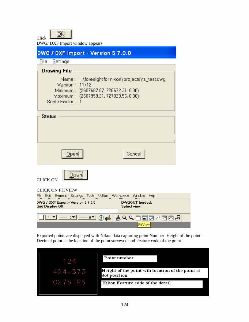
124
Click
DWG/ DXF Import window appears
CLICK ON
CLICK ON FITVIEW
Exported points are displayed with Nikon data capturing point Number .Height of the point.
Decimal point is the location of the point surveyed and feature code of the point

125
(YOUR 500.DGN FILE WILL DISPLY ON SCREEN YOU CAN USE THE CELL LIBRARY
FOR SYMBOLOGY)
C: HOW TO CREATE A NEW DGN FILE IN MICROSTATION:
CLICK FILE FROM MICROSTATION MANAGER AND CHOOSE NEW
THE CREATE DESIGN FILE DIALOG BOX WILL BE OPEN
THE DEFAULT IS *.dgn IN THE LIST FILE
TYPE DROP-DOWN LIST (THIS CAN BE CHANGED AS PER THE REQUIREMENTS)
THE DEFAULT SEED FILE IS SEED 2d.dgn DISPLAYED IN THE SEED FILE SECTION
TO SELECT A DIFFERENT SEED DESIGN FILE:
CLICK AT SELECT BUTTON (SEED FILE DIALOG BOX OPENS)
IN THE FILE LIST BOX SELECT THE DESIRED SEED FILE
CLICK OK
IN THE FILES FIELD KEY IN A NAME FOR THE NEW DESIGN FILE
CLLICK THE OK BUTTON
D: HOW TO SET THE WORKING UNITS:
CLICK ON SETTING FROM THE TOPO MENU BAR
SELECT DGN FILE (DGN FILE SETTING BOX OPENS)
SELECT WORKING UNIT FROM THE CATEGORY LIST BOX
KEY IN ―M‖ IN MASTER UNIT
KEY IN ―CM‖ IN SUB UNIT
KEY IN 100 CM PER M AND 1 POSITIONAL UNITS PER CM (BECAUSE TOTAL
STATION DATAS ARE IN GROUND TERMS)
CLICK OK
******************************************************************************
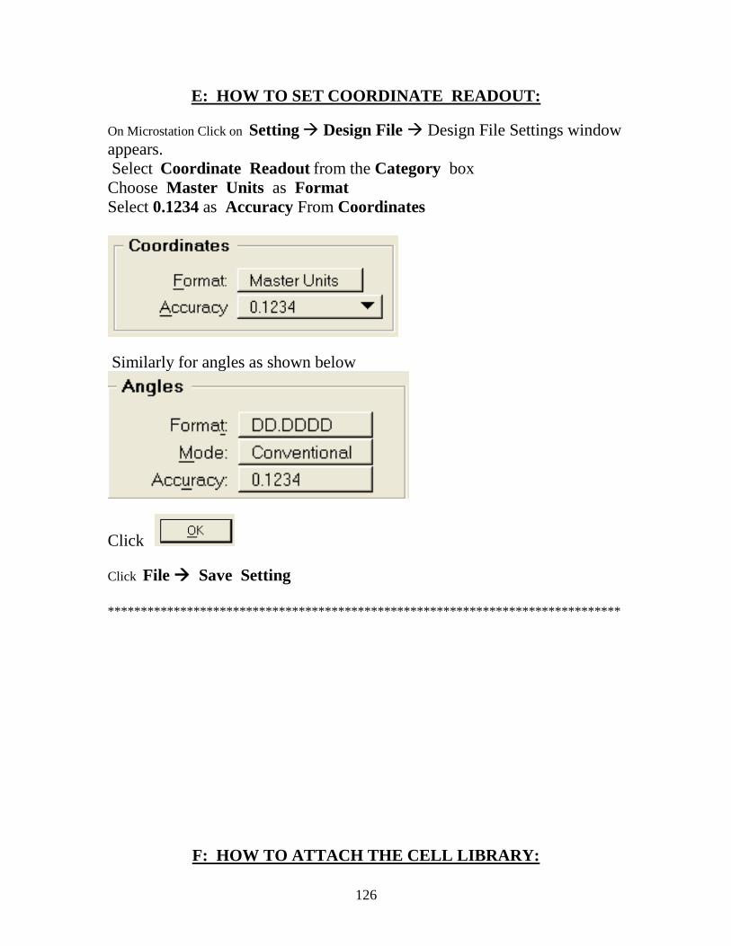
126
E: HOW TO SET COORDINATE READOUT:
On Microstation Click on Setting Design File Design File Settings window
appears.
Select Coordinate Readout from the Category box
Choose Master Units as Format
Select 0.1234 as Accuracy From Coordinates
Similarly for angles as shown below
Click
Click File Save Setting
******************************************************************************
F: HOW TO ATTACH THE CELL LIBRARY:
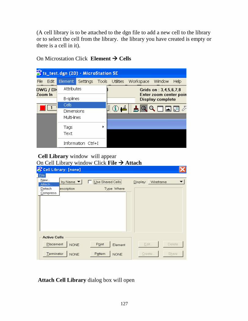
127
(A cell library is to be attached to the dgn file to add a new cell to the library
or to select the cell from the library. the library you have created is empty or
there is a cell in it).
On Microstation Click Element Cells
Cell Library window will appear
On Cell Library window Click File Attach
Attach Cell Library dialog box will open
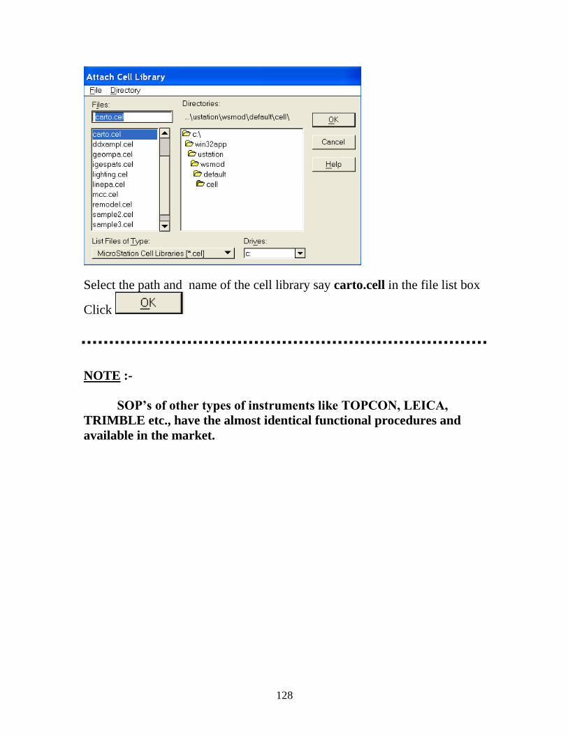
128
Select the path and name of the cell library say carto.cell in the file list box
Click
NOTE :-
SOP’s of other types of instruments like TOPCON, LEICA,
TRIMBLE etc., have the almost identical functional procedures and
available in the market.
129
FOR MORE INFORMATION PLEASE REFER
THE FOLLOWING MANUALS:
1 AP 800 FIELD INFORMATION SYSTEM
REFERENCE MANUAL.
2 FIELD STATION DTM-801 SERIES DTM-
851/DTM-831/DTM-821 INSTRUCTION MANUAL.
3 FORE SIGHT FOR NIKON BY TDS USER’S
MANUAL.


![[D&D 3.5e - Eng] Monster Manual IV.pdf](https://img.pdfslide.us/doc/110x75/577c7c351a28abe05499bd08/dd-35e-eng-monster-manual-ivpdf.jpg)